Embed Size (px)
Citation preview
ModiconRemote I/O Cable
System Planning and Installation Guide890 USE 101 00
April, 1996
AEG Schneider Automation, Inc.One High Street
North Andover , MA 01845

Preface890 USE 101 00 iii
Preface
The data and illustrations found in this book are not binding. We reserve theright to modify our products in line with our policy of continuous productimprovement. Information in this document is subject to change without noticeand should not be construed as a commitment by Modicon, Inc., IndustrialAutomation Systems. Modicon, Inc. assumes no responsibility for any errorsthat may appear in this document.
No part of this document may be reproduced in any form or by any means,electronic or mechanical, without the express written permission of Modicon,Inc., Industrial Automation Systems. All rights reserved.
The following are trademarks of Modicon, Inc.:
Modbus Modbus PlusModbus II Quantum Automation Series984
MODSOFT is a registered trademark of Modicon, Inc.
IBM is a registered trademark of International Business MachinesCorporation. IBM AT, IBM XT, Micro Channel, Personal System/2, andNetBIOS are trademarks of International Business Machines Corporation.
Microsoft and MS-DOS are registered trademarks of Microsoft Corporation.
Copyright 1996 by Modicon, Inc. All rights reserved.Printed in U. S. A.
890 USE 101 00iv Preface
Scope of this Manual
This manual is intended for the design engineer, cable system installer, andnetwork manager involved with a Modicon Remote I/O (RIO) network. Themanual describes
V Design, installation, test, and maintenance procedures for the RIO network
V Required media hardware—e.g., cables, taps, connectors, fiber optic op-tions, tools—and approved optional hardware for special situations and en-vironments
V RIO communication processing devices used with the Quantum AutomationSeries CPUs and the 984 family of PLCs
V Recommended installation and maintenance tests for the RIO network
Objectives
This manual can be used as a planning tool to assist the design team in makingits preliminary decisions about RIO system requirements, as a system designaid, as a reference for the cable system installation, and as a guide to testingand maintaining the network. It should be used in conjunction with theinstallation manuals for the the particular PLC, RIO processing nodes(head-end processors and drop adapters), and I/O modules to be used in yoursystem.
The discussions are hardware-related, with a detailed emphasis on the RIOnetwork cable system. Programming and panel software issues are notdiscussed. For specific details related to hardware settings on the PLC, the I/Omodules, and the processing nodes, refer to those modules’ specific installationguides.
How this Manual Is Organized
Chapter 1 is an overview of how an RIO network operates, listing thecommunication protocols, and key system hardware components.
Chapter 2 provides a series of illustrated cable topology models over which anRIO network may be implemented. In addition to standard linear, dual, andredundant cabling topologies, various optional approaches using Hot Standby
Preface890 USE 101 00 v
control modules and fiber optic repeaters are shown. It also presents somebasic planning considerations such as:
V How to select appropriate installation environments
V Selection criteria for various cable media and other standard and optionalhardware requirements
V Techniques for calculating attenuation on your cable system and for estab-lishing suitable spacing between taps on the main (trunk) cable
Documentation templates are also provided to help you maintain a good recordof your installation plan.
Chapter 3 lists the performance specifications for the cable types that havebeen approved for use on the 984 RIO network and describes in detail thevarious other required and optional hardware components that may be used inan RIO cable installation.
Chapter 4 provides descriptions of the various tasks required to install the RIOcable system.
Chapter 5 provides an overview of the test procedures that should be performedto verify the integrity of the cable installation and some troubleshootingsuggestions for isolating problem sources on the network.

Table of Contents890 USE 101 00 vii
Table of Contents
Chapter 1 Remote I/O Networks—A Communications Overview 1. . . . . . .
1.1 RIO Network Communications 2. . . . . . . . . . . . . . . . . . . . . . . . . . . . . . . . . . . . . . . . .Data Transfer Consistency 2. . . . . . . . . . . . . . . . . . . . . . . . . . . . . . . . . . . . . . . .Predictable Speeds for Time-critical Applications 2. . . . . . . . . . . . . . . . . . . . .
1.2 Processing Nodes on the RIO Network 3. . . . . . . . . . . . . . . . . . . . . . . . . . . . . . . . .RIO Processors 3. . . . . . . . . . . . . . . . . . . . . . . . . . . . . . . . . . . . . . . . . . . . . . . . .RIO Adapters 4. . . . . . . . . . . . . . . . . . . . . . . . . . . . . . . . . . . . . . . . . . . . . . . . . . .
1.3 RIO Network Communications 6. . . . . . . . . . . . . . . . . . . . . . . . . . . . . . . . . . . . . . . . .Setting Drop Addresses 6. . . . . . . . . . . . . . . . . . . . . . . . . . . . . . . . . . . . . . . . . .How Messages Are Transmitted 6. . . . . . . . . . . . . . . . . . . . . . . . . . . . . . . . . . .
1.4 The RIO Network Cable System 7. . . . . . . . . . . . . . . . . . . . . . . . . . . . . . . . . . . . . . .Trunk Cable 7. . . . . . . . . . . . . . . . . . . . . . . . . . . . . . . . . . . . . . . . . . . . . . . . . . . . .Taps 7. . . . . . . . . . . . . . . . . . . . . . . . . . . . . . . . . . . . . . . . . . . . . . . . . . . . . . . . . . .Drop Cable 7. . . . . . . . . . . . . . . . . . . . . . . . . . . . . . . . . . . . . . . . . . . . . . . . . . . . .Terminating the Cable System 7. . . . . . . . . . . . . . . . . . . . . . . . . . . . . . . . . . . . .
1.5 Modicon Network Services 9. . . . . . . . . . . . . . . . . . . . . . . . . . . . . . . . . . . . . . . . . . . .1.6 RIO Network Node Part Numbers 10. . . . . . . . . . . . . . . . . . . . . . . . . . . . . . . . . . . . .
Chapter 2 Planning and Designing an RIO Cable System 11. . . . . . . . . . . .
2.1 Linear Cable Topologies 12. . . . . . . . . . . . . . . . . . . . . . . . . . . . . . . . . . . . . . . . . . . . .Standard Single-cable RIO Cable Systems 12. . . . . . . . . . . . . . . . . . . . . . . . .Redundant RIO Cable Systems 13. . . . . . . . . . . . . . . . . . . . . . . . . . . . . . . . . . .Dual Cable Systems 14. . . . . . . . . . . . . . . . . . . . . . . . . . . . . . . . . . . . . . . . . . . .
2.2 Hot Standby Cable Topologies (for 984 PLCs) 15. . . . . . . . . . . . . . . . . . . . . . . . . .Single-cable Hot Standby Systems 15. . . . . . . . . . . . . . . . . . . . . . . . . . . . . . . .Redundant Hot Standby Cable Systems 16. . . . . . . . . . . . . . . . . . . . . . . . . . .
2.3 Illegal Coaxial Cable Topologies 17. . . . . . . . . . . . . . . . . . . . . . . . . . . . . . . . . . . . . .Using a Splitter as a Branching Device 17. . . . . . . . . . . . . . . . . . . . . . . . . . . .Illegal Trunk Cable Termination 18. . . . . . . . . . . . . . . . . . . . . . . . . . . . . . . . . . .Open Taps 18. . . . . . . . . . . . . . . . . . . . . . . . . . . . . . . . . . . . . . . . . . . . . . . . . . . . .Illegal Trunk Cable Connections 19. . . . . . . . . . . . . . . . . . . . . . . . . . . . . . . . . .Illegal Drop Cable Connections 19. . . . . . . . . . . . . . . . . . . . . . . . . . . . . . . . . . .
2.4 Using Fiber Optics in an RIO System 20. . . . . . . . . . . . . . . . . . . . . . . . . . . . . . . . .Point-to-point Topology with Fiber Optics 20. . . . . . . . . . . . . . . . . . . . . . . . . . .Bus Topology with Fiber Optics 22. . . . . . . . . . . . . . . . . . . . . . . . . . . . . . . . . . .Star and Tree Topologies with Fiber Optics 23. . . . . . . . . . . . . . . . . . . . . . . . .Self-healing Ring Fiber Optic Topology 25. . . . . . . . . . . . . . . . . . . . . . . . . . . .
2.5 RIO System Design 26. . . . . . . . . . . . . . . . . . . . . . . . . . . . . . . . . . . . . . . . . . . . . . . . .
890 USE 101 00viii Table of Contents
Key Elements in a Cable System Plan 26. . . . . . . . . . . . . . . . . . . . . . . . . . . . .Planning for System Expansion 27. . . . . . . . . . . . . . . . . . . . . . . . . . . . . . . . . . .
2.6 Choosing Coaxial Cables for an RIO Network 28. . . . . . . . . . . . . . . . . . . . . . . . . .Coaxial Cable Construction 28. . . . . . . . . . . . . . . . . . . . . . . . . . . . . . . . . . . . . .Flexible Cable 29. . . . . . . . . . . . . . . . . . . . . . . . . . . . . . . . . . . . . . . . . . . . . . . . . .Semirigid Cable 29. . . . . . . . . . . . . . . . . . . . . . . . . . . . . . . . . . . . . . . . . . . . . . . .
2.7 Coaxial Cable Characteristics 30. . . . . . . . . . . . . . . . . . . . . . . . . . . . . . . . . . . . . . . .Cable Bend Radius 30. . . . . . . . . . . . . . . . . . . . . . . . . . . . . . . . . . . . . . . . . . . . .Cable Support 30. . . . . . . . . . . . . . . . . . . . . . . . . . . . . . . . . . . . . . . . . . . . . . . . . .Cable Pull Strength 30. . . . . . . . . . . . . . . . . . . . . . . . . . . . . . . . . . . . . . . . . . . . .Environmental Considerations 30. . . . . . . . . . . . . . . . . . . . . . . . . . . . . . . . . . . .
2.8 Electrical Characteristics of Coaxial Media Components 32. . . . . . . . . . . . . . . . .Impedance 32. . . . . . . . . . . . . . . . . . . . . . . . . . . . . . . . . . . . . . . . . . . . . . . . . . . . .Attenuation 32. . . . . . . . . . . . . . . . . . . . . . . . . . . . . . . . . . . . . . . . . . . . . . . . . . . .Return Loss 33. . . . . . . . . . . . . . . . . . . . . . . . . . . . . . . . . . . . . . . . . . . . . . . . . . . .
2.9 EMI/RFI Considerations in a Coaxial Cable Routing Plan 34. . . . . . . . . . . . . . . .Guidelines for Interference Avoidance 34. . . . . . . . . . . . . . . . . . . . . . . . . . . . .
2.10 Tap Connections and Locations 35. . . . . . . . . . . . . . . . . . . . . . . . . . . . . . . . . . . . . .Using Band Marked Trunk Cable 35. . . . . . . . . . . . . . . . . . . . . . . . . . . . . . . . .Tap Port Connections 35. . . . . . . . . . . . . . . . . . . . . . . . . . . . . . . . . . . . . . . . . . .Optional Tap Enclosure Considerations 36. . . . . . . . . . . . . . . . . . . . . . . . . . . .
2.11 Grounding and Surge Suppression 37. . . . . . . . . . . . . . . . . . . . . . . . . . . . . . . . . . . .Earth Ground 37. . . . . . . . . . . . . . . . . . . . . . . . . . . . . . . . . . . . . . . . . . . . . . . . . .Lightning Protection for RIO Cable Systems 37. . . . . . . . . . . . . . . . . . . . . . . .
2.12 Terminating a Coaxial Cable System 38. . . . . . . . . . . . . . . . . . . . . . . . . . . . . . . . . .Terminating the Trunk Cable 38. . . . . . . . . . . . . . . . . . . . . . . . . . . . . . . . . . . . .Terminating Unused Tap Ports 38. . . . . . . . . . . . . . . . . . . . . . . . . . . . . . . . . . . .Terminating the Drops 38. . . . . . . . . . . . . . . . . . . . . . . . . . . . . . . . . . . . . . . . . . .
2.13 Designing a Coaxial Cable System to an Attenuation Limit 39. . . . . . . . . . . . . . .Cable Attenuation 39. . . . . . . . . . . . . . . . . . . . . . . . . . . . . . . . . . . . . . . . . . . . . . .Tap Attenuation 39. . . . . . . . . . . . . . . . . . . . . . . . . . . . . . . . . . . . . . . . . . . . . . . . .Calculating Maximum System Attenuation 40. . . . . . . . . . . . . . . . . . . . . . . . . .Calculating Attenuation on a Coaxial Network—An Example 40. . . . . . . . . .
2.14 Calculating Attenuation on an Optical Path 43. . . . . . . . . . . . . . . . . . . . . . . . . . . . .Minimum Distance between Repeaters 43. . . . . . . . . . . . . . . . . . . . . . . . . . . .Example—Attenuation on a Simple Optical Link 44. . . . . . . . . . . . . . . . . . . . .Example—An Optical Link with a Star Coupler 45. . . . . . . . . . . . . . . . . . . . . .
2.15 Pulse Width Distortion in a Fiber Optic Bus Topology 46. . . . . . . . . . . . . . . . . . . .Example—Calculating Repeaters on a 10 km Optical Path 46. . . . . . . . . . .
2.16 Planning RIO Drops 48. . . . . . . . . . . . . . . . . . . . . . . . . . . . . . . . . . . . . . . . . . . . . . . . .Connecting the Drop Cable to the Drop Adapter 48. . . . . . . . . . . . . . . . . . . .Minimizing Low Receive Signal Level Problems 49. . . . . . . . . . . . . . . . . . . . .Documenting Your Cable System Design 49. . . . . . . . . . . . . . . . . . . . . . . . . .
Table of Contents890 USE 101 00 ix
Chapter 3 RIO Network Hardware Components 53. . . . . . . . . . . . . . . . . . . . . .
3.1 RG-6 Cable 54. . . . . . . . . . . . . . . . . . . . . . . . . . . . . . . . . . . . . . . . . . . . . . . . . . . . . . . .Modicon RG-6 Cable 54. . . . . . . . . . . . . . . . . . . . . . . . . . . . . . . . . . . . . . . . . . . .Other Approved RG-6 Cables 55. . . . . . . . . . . . . . . . . . . . . . . . . . . . . . . . . . . .Approved RG-6 Plenum Cable 56. . . . . . . . . . . . . . . . . . . . . . . . . . . . . . . . . . .
3.2 RG-11 Cable 57. . . . . . . . . . . . . . . . . . . . . . . . . . . . . . . . . . . . . . . . . . . . . . . . . . . . . . .Modicon RG-11 Cable 57. . . . . . . . . . . . . . . . . . . . . . . . . . . . . . . . . . . . . . . . . . .Other Approved RG-11 Cables 57. . . . . . . . . . . . . . . . . . . . . . . . . . . . . . . . . . .Approved RG-11 Armored and Plenum Cables 60. . . . . . . . . . . . . . . . . . . . .
3.3 Approved Semirigid Cables 61. . . . . . . . . . . . . . . . . . . . . . . . . . . . . . . . . . . . . . . . . .3.4 Selecting Fiber Optic Cable 65. . . . . . . . . . . . . . . . . . . . . . . . . . . . . . . . . . . . . . . . . .3.5 Hardware Overview 66. . . . . . . . . . . . . . . . . . . . . . . . . . . . . . . . . . . . . . . . . . . . . . . . .
Required Cable System Hardware Components 66. . . . . . . . . . . . . . . . . . . .Optional Cable System Hardware Components 66. . . . . . . . . . . . . . . . . . . . .The Optional RIO Fiber Optics Repeater 66. . . . . . . . . . . . . . . . . . . . . . . . . . .RIO System Hardware Components 67. . . . . . . . . . . . . . . . . . . . . . . . . . . . . . .
3.6 Tap Specifications 68. . . . . . . . . . . . . . . . . . . . . . . . . . . . . . . . . . . . . . . . . . . . . . . . . .3.7 Splitter Specifications 70. . . . . . . . . . . . . . . . . . . . . . . . . . . . . . . . . . . . . . . . . . . . . . .3.8 F Connectors for Coaxial Cables 72. . . . . . . . . . . . . . . . . . . . . . . . . . . . . . . . . . . . .
F Connectors for Quad Shield RG-6 Cable 72. . . . . . . . . . . . . . . . . . . . . . . . .F Connectors for Non-quad Shield RG-6 Cable 72. . . . . . . . . . . . . . . . . . . . .F Connectors for RG-11 Cable 73. . . . . . . . . . . . . . . . . . . . . . . . . . . . . . . . . . .
3.9 F Adapters for Semirigid Cable 74. . . . . . . . . . . . . . . . . . . . . . . . . . . . . . . . . . . . . . .3.10 BNC Connectors and Adapters 75. . . . . . . . . . . . . . . . . . . . . . . . . . . . . . . . . . . . . . .
BNC Connectors for RG-6 Cable 75. . . . . . . . . . . . . . . . . . . . . . . . . . . . . . . . .F-to-BNC Adapters for RG-11 Cable 75. . . . . . . . . . . . . . . . . . . . . . . . . . . . . .BNC Jack to Male F Connector 76. . . . . . . . . . . . . . . . . . . . . . . . . . . . . . . . . . .
3.11 Network Terminators 77. . . . . . . . . . . . . . . . . . . . . . . . . . . . . . . . . . . . . . . . . . . . . . . .Tap Port Terminators 77. . . . . . . . . . . . . . . . . . . . . . . . . . . . . . . . . . . . . . . . . . . .Trunk Terminators 77. . . . . . . . . . . . . . . . . . . . . . . . . . . . . . . . . . . . . . . . . . . . . .BNC In-line Terminators 78. . . . . . . . . . . . . . . . . . . . . . . . . . . . . . . . . . . . . . . . .Self-terminating BNC Adapters for Hot Standby Systems 78. . . . . . . . . . . .Warning Labels 79. . . . . . . . . . . . . . . . . . . . . . . . . . . . . . . . . . . . . . . . . . . . . . . . .
3.12 Self-terminating F Adapter Options 80. . . . . . . . . . . . . . . . . . . . . . . . . . . . . . . . . . . .Self-terminating F Adapters 80. . . . . . . . . . . . . . . . . . . . . . . . . . . . . . . . . . . . . .Warning Labels 81. . . . . . . . . . . . . . . . . . . . . . . . . . . . . . . . . . . . . . . . . . . . . . . . .
3.13 Ground Blocks 82. . . . . . . . . . . . . . . . . . . . . . . . . . . . . . . . . . . . . . . . . . . . . . . . . . . . .3.14 Surge Suppressors 83. . . . . . . . . . . . . . . . . . . . . . . . . . . . . . . . . . . . . . . . . . . . . . . . .3.15 Cable Waterproofing Materials 84. . . . . . . . . . . . . . . . . . . . . . . . . . . . . . . . . . . . . . . .3.16 Fiber Optic Repeater 85. . . . . . . . . . . . . . . . . . . . . . . . . . . . . . . . . . . . . . . . . . . . . . . .
Repeater Indicator LEDs 86. . . . . . . . . . . . . . . . . . . . . . . . . . . . . . . . . . . . . . . . .RIO Shield-to-Chassis Jumper 86. . . . . . . . . . . . . . . . . . . . . . . . . . . . . . . . . . . .
3.17 Recommended Materials for Fiber Optic Links 88. . . . . . . . . . . . . . . . . . . . . . . . . .Connectors 88. . . . . . . . . . . . . . . . . . . . . . . . . . . . . . . . . . . . . . . . . . . . . . . . . . . .

890 USE 101 00x Table of Contents
Termination Kits 88. . . . . . . . . . . . . . . . . . . . . . . . . . . . . . . . . . . . . . . . . . . . . . . .Passive Couplers 88. . . . . . . . . . . . . . . . . . . . . . . . . . . . . . . . . . . . . . . . . . . . . . .Other Tools 89. . . . . . . . . . . . . . . . . . . . . . . . . . . . . . . . . . . . . . . . . . . . . . . . . . . .
Chapter 4 Installing an RIO Network 91. . . . . . . . . . . . . . . . . . . . . . . . . . . . . . . .
4.1 Installation Overview 92. . . . . . . . . . . . . . . . . . . . . . . . . . . . . . . . . . . . . . . . . . . . . . . .4.2 RG-6 Cable Connections 93. . . . . . . . . . . . . . . . . . . . . . . . . . . . . . . . . . . . . . . . . . . .
Installation Tools 93. . . . . . . . . . . . . . . . . . . . . . . . . . . . . . . . . . . . . . . . . . . . . . . .4.3 RG-6 Installation Tools 94. . . . . . . . . . . . . . . . . . . . . . . . . . . . . . . . . . . . . . . . . . . . . .
RG-6 Cable Installation Tool 94. . . . . . . . . . . . . . . . . . . . . . . . . . . . . . . . . . . . . .Crimp Tool 95. . . . . . . . . . . . . . . . . . . . . . . . . . . . . . . . . . . . . . . . . . . . . . . . . . . . .Cable Cutters 95. . . . . . . . . . . . . . . . . . . . . . . . . . . . . . . . . . . . . . . . . . . . . . . . . .
4.4 Preparing RG-6 Cable for a Connector 96. . . . . . . . . . . . . . . . . . . . . . . . . . . . . . . .4.5 Installing F Connectors on Quad Shield RG-6 Cable 98. . . . . . . . . . . . . . . . . . . .4.6 Installing F Connectors on Non-quad Shield RG-6 Cable 101. . . . . . . . . . . . . . . .4.7 Installing BNC or Self-terminating F Connectors on RG-6 Cable 103. . . . . . . . .4.8 Making RG-11 F Connections 105. . . . . . . . . . . . . . . . . . . . . . . . . . . . . . . . . . . . . . .
Required Tools 105. . . . . . . . . . . . . . . . . . . . . . . . . . . . . . . . . . . . . . . . . . . . . . . .4.9 The RG-11 Installation Tool 106. . . . . . . . . . . . . . . . . . . . . . . . . . . . . . . . . . . . . . . . .
4.10 Preparing an RG-11 Cable for a Connector 107. . . . . . . . . . . . . . . . . . . . . . . . . . .4.11 Installing F Connectors on RG-11 Cable 109. . . . . . . . . . . . . . . . . . . . . . . . . . . . . .4.12 Providing Line Termination on the Drop Cable 112. . . . . . . . . . . . . . . . . . . . . . . . .
Installing a BNC In-line Terminator on a Drop Cable 112. . . . . . . . . . . . . . . .Optional Drop Cable In-line Termination 113. . . . . . . . . . . . . . . . . . . . . . . . . . .
4.13 Connecting/Disconnecting a Drop Cable at a Tap 114. . . . . . . . . . . . . . . . . . . . . .4.14 Installing Fiber Optic Repeaters 116. . . . . . . . . . . . . . . . . . . . . . . . . . . . . . . . . . . . .
Mounting a Repeater 116. . . . . . . . . . . . . . . . . . . . . . . . . . . . . . . . . . . . . . . . . . .Connecting the Network Cables 117. . . . . . . . . . . . . . . . . . . . . . . . . . . . . . . . .RIO Shield-to-Chassis Jumper 117. . . . . . . . . . . . . . . . . . . . . . . . . . . . . . . . . . .Connecting Power 117. . . . . . . . . . . . . . . . . . . . . . . . . . . . . . . . . . . . . . . . . . . . .
4.15 Terminating the Trunk Cable 120. . . . . . . . . . . . . . . . . . . . . . . . . . . . . . . . . . . . . . . .4.16 Installing the Ground Point 121. . . . . . . . . . . . . . . . . . . . . . . . . . . . . . . . . . . . . . . . . .
Chapter 5 Testing and Maintaining an RIO Network 123. . . . . . . . . . . . . . . . .
5.1 Maintenance and Testing Requirements 124. . . . . . . . . . . . . . . . . . . . . . . . . . . . . .Documenting Drop Maintenance Information 124. . . . . . . . . . . . . . . . . . . . . .
5.2 RIO System Tests 126. . . . . . . . . . . . . . . . . . . . . . . . . . . . . . . . . . . . . . . . . . . . . . . . .Fundamental RIO System Tests 126. . . . . . . . . . . . . . . . . . . . . . . . . . . . . . . . .RIO System Tests for Critical Applications 127. . . . . . . . . . . . . . . . . . . . . . . .Network Startup 128. . . . . . . . . . . . . . . . . . . . . . . . . . . . . . . . . . . . . . . . . . . . . . .

Table of Contents890 USE 101 00 xi
5.3 Problem Sources on an RIO Network 129. . . . . . . . . . . . . . . . . . . . . . . . . . . . . . . .Solving Spacing Problems 129. . . . . . . . . . . . . . . . . . . . . . . . . . . . . . . . . . . . . .Potential Grounding Problems 129. . . . . . . . . . . . . . . . . . . . . . . . . . . . . . . . . . .Problems Stemming from Poor Installation 130. . . . . . . . . . . . . . . . . . . . . . . .
5.4 On-line and Off-line Error Isolation 131. . . . . . . . . . . . . . . . . . . . . . . . . . . . . . . . . .5.5 Troubleshooting Fiber Optic Repeaters 132. . . . . . . . . . . . . . . . . . . . . . . . . . . . . . .
Broken Cable Detection and Remedies 133. . . . . . . . . . . . . . . . . . . . . . . . . . .
Appendix A RIO Cable Material Suppliers 135. . . . . . . . . . . . . . . . . . . . . . . . . .
Appendix B Glossary 137. . . . . . . . . . . . . . . . . . . . . . . . . . . . . . . . . . . . . . . . . . . . .
Index 145. . . . . . . . . . . . . . . . . . . . . . . . . . . . . . . . . . . . . . . . . . . . . . . . . . . . . .
Communications Overview890 USE 101 00 1
Chapter 1Remote I/O Networks: ACommunications Overview
V RIO Network Communications
V Processing Nodes on the RIO Network
V RIO Network Communications
V The RIO Network Cable System
V Modicon Network Services
V RIO Network Node Part Numbers
890 USE 101 002 Communications Overview
1.1 RIO Network Communications
Modicon’s RIO network is a high speed (1.544 Mbit/s) local area network (LAN)that uses commercially available coaxial cable and CATV media technology.RIO supports:
V Discrete and register data to input and output module communications
V ASCII message transmissions to and from certain RIO drop adapters
1.1.1 Data Transfer Consistency
An RIO network provides high speed data transfer. Most data transfersbetween the RIO processor (at the PLC head-end) and the RIO adapters (at theremote drops) take less than 1 ms for one drop of I/O.
PLCs service their drop adapters only at the end of logic segments. Multiplelogic segments may be serviced in one scan. Updating RIO data at the end ofsegment ensures consistent data throughput. A (CRC16) message framecheck assures that RIO messages will arrive reliably and completelyerror-checked at the proper destination node
1.1.2 Predictable Speeds for Time-critical Applications
As a high speed LAN, RIO must support applications that are very time-critical.In this respect, RIO has several advantages over other proprietary PLCcommunication methods:
V Its HDLC protocol implementation makes the RIO data transfer speed verypredictable
V The PLC services each node using a consistent communications method—the I/O drops are always updated in a determinate time period that can becalculated based on the number of segments in the user logic program
V Only one node transmits at a given time, so message collisions do not oc-cur—each node is able to transmit on the network in a determinate timeperiod
V RIO has high data integrity due to the frame check sequence and errorchecking at the physical protocol layer
Communications Overview890 USE 101 00 3
1.2 Processing Nodes on the RIO Network
The RIO network supports communications between a PLC and one or moredrops of I/O modules dispersed throughout your local area—e.g., yourmanufacturing or processing facility. All messages on the RIO network areinitiated by a master node called the RIO head or processor . All other nodes onthe network communicate with the RIO head via RIO adapters located at thedrops. The network is proprietary, and Modicon processing nodes must beused throughout the RIO network.
1.2.1 RIO Processors
RIO is fundamentally a single-master network, and the RIO processor is themaster node. The RIO processor is located at the PLC at the head-end of theRIO network. Depending on the type of PLC you are using, the RIO processorcan be implemented in hardware as an option module that mounts beside thePLC or as a board built into the PLC.
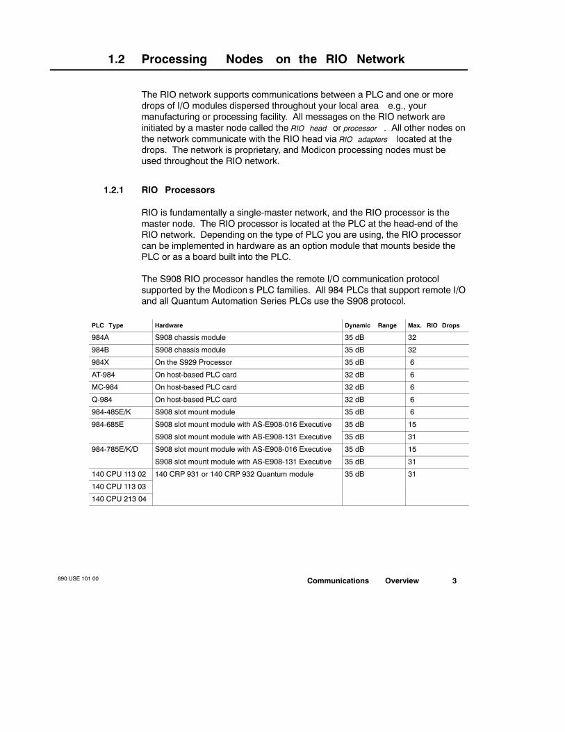
The S908 RIO processor handles the remote I/O communication protocolsupported by the Modicon’s PLC families. All 984 PLCs that support remote I/Oand all Quantum Automation Series PLCs use the S908 protocol.
PLC Type Hardware Dynamic Range Max. RIO Drops
984A S908 chassis module 35 dB 32
984B S908 chassis module 35 dB 32
984X On the S929 Processor 35 dB 6
AT-984 On host-based PLC card 32 dB 6
MC-984 On host-based PLC card 32 dB 6
Q-984 On host-based PLC card 32 dB 6
984-485E/K S908 slot mount module 35 dB 6
984-685E S908 slot mount module with AS-E908-016 Executive 35 dB 15
S908 slot mount module with AS-E908-131 Executive 35 dB 31
984-785E/K/D S908 slot mount module with AS-E908-016 Executive 35 dB 15
S908 slot mount module with AS-E908-131 Executive 35 dB 31
140 CPU 113 02 140 CRP 931 or 140 CRP 932 Quantum module 35 dB 31
140 CPU 113 03
140 CPU 213 04

890 USE 101 004 Communications Overview
1.2.2 RIO Adapters
An adapter module resides at each remote drop on the RIO network. The typeof adapter used depends on:
V The type of RIO processor at the head-end of the network
V The series of I/O modules at the drop
V Whether or not ASCII devices are being supported at the drop
V Whether the drop adapter will support one or two RIO cables
Drop Adapter Head Processor I/O at the Drop ASCII Ports RIO Cable Ports
140 CRA 931 00 140 CRP 931 00 Quantum N/A 1
140 CRA 932 00 140 CRP 932 00 Quantum N/A 2
AS-J890-101 S908 800 0 1
AS-J890-102 S908 800 0 2
AS-J892-101 S908 800 2 1
AS-J892-102 S908 800 2 2
AS-P890-000 S908 800 0 1
AS-P892-000 S908 800 2 1
Communications Overview890 USE 101 00 5
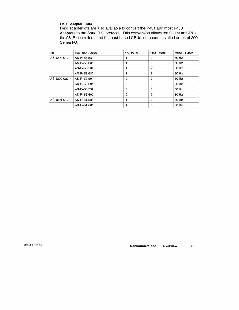
Field Adapter KitsField adapter kits are also available to convert the P451 and most P453Adapters to the S908 RIO protocol. This conversion allows the Quantum CPUs,the 984E controllers, and the host-based CPUs to support installed drops of 200Series I/O.
Kit New RIO Adapter RIO Ports ASCII Ports Power Supply
AS-J290-010 AS-P453-581 1 0 50 Hz
AS-P453-681 1 0 60 Hz
AS-P453-582 1 2 50 Hz
AS-P453-682 1 2 60 Hz
AS-J290-020 AS-P453-591 2 0 50 Hz
AS-P453-691 2 0 60 Hz
AS-P453-592 2 2 50 Hz
AS-P453-692 2 2 60 Hz
AS-J291-010 AS-P451-581 1 0 50 Hz
AS-P451-681 1 0 60 Hz

890 USE 101 006 Communications Overview
1.3 RIO Network Communications
Each RIO drop adapter on the network must be assigned a unique addressnumber. The RIO processor uses this drop address to send I/O module data orASCII message data to the proper adapter. The physical location of an adapteron the network has no bearing on its address or on the data throughput, makingthe RIO network a true bus architecture.
1.3.1 Setting Drop Addresses
RIO drop adapters have switches on them that are used to set the unique RIOdrop address and ASCII port addresses (if ASCII devices are supported at thedrops). DIP switches are used on the 984 type adapters, and rotary switchesare used on Quantum adapters. Consult the hardware documentation forlocation of the switches and appropriate settings.
1.3.2 How Messages Are Transmitted
A message initiated by the RIO head processor travels along the network’scable system and is received by all RIO adapters. The RIO adapter with theaddress specified in the message can then transmit a response message backto the RIO head within a specific time period. If the drop adapter does notrespond, the same message is sent again. The process of resending themessage after no response is called a retry .
If the adapter does not respond to several retries, the drop is declared dead.On each successive scan of the PLC, the RIO head attempts to re-establishcommunications with the adapter—only one attempt per scan will be made tocommunicate with a dead drop until the adapter is successfully brought backup.

Communications Overview890 USE 101 00 7
1.4 The RIO Network Cable System
The RIO processor at the controller head-end is connected to an adapter ateach of the remote drops via a network cable system.
1.4.1 Trunk Cable
Starting at the RIO processor and running the entire length of the network areone (linear) or two (dual or redundant) trunk cable(s). Taps are installed alongthe length of the trunk cable(s), and a drop cable is run from a tap to a dropadapter. The trunk cable may be an approved flexible or semirigid coaxial type,as specified in Chapter 3.
1.4.2 Taps
The taps connect the drop adapter at each drop to the trunk cable via a dropcable, providing each adapter with a portion of the signal that is on the trunk.The taps also isolate each drop adapter from all other drop adapters on thenetwork so that they won’t interfere with each other.
1.4.3 Drop Cable
Extending from a tap to an adapter is a drop cable. The drop cable connects tothe tap with an F connector, and it connects to the adapter with either an Fconnector or a BNC connector, depending on the type of RIO adapter at thedrop (see Section 2.16). The drop cable may be an approved coaxial type, asspecified in Chapter 3.
1.4.4 Terminating the Cable System
A proper impedance match is maintained across the network with 75 Ωterminators. You must install a 75 Ω terminator:
V In the unused trunk port of the last tap on the network to terminate the trunkcable
V In any open drop cable ports on taps that have been installed for future sys-tem expansion
V In-line on cables running from the primary and standby controllers to thesplitter in a Hot Standby system; this allows you to disconnect one of thetwo Hot Standby controllers while the other one maintains primary control
890 USE 101 008 Communications Overview
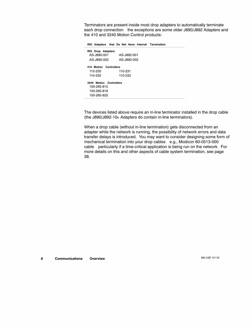
Terminators are present inside most drop adapters to automatically terminateeach drop connection—the exceptions are some older J890/J892 Adapters andthe 410 and 3240 Motion Control products:
RIO Adapters that Do Not Have Internal Termination
RIO Drop AdaptersAS-J890-001AS-J890-002
AS-J892-001AS-J890-002
410 Motion Controllers
110-230 110-231110-232 110-233
3240 Motion Controllers100-265-815100-265-816100-265-825
The devices listed above require an in-line terminator installed in the drop cable(the J890/J892-10x Adapters do contain in-line terminators).
When a drop cable (without in-line termination) gets disconnected from anadapter while the network is running, the possibility of network errors and datatransfer delays is introduced. You may want to consider designing some form ofmechanical termination into your drop cables—e.g., Modicon 60-0513-000cable—particularly if a time-critical application is being run on the network. Formore details on this and other aspects of cable system termination, see page38.

Communications Overview890 USE 101 00 9
1.5 RIO Network Node Part Numbers
RIO Device Type One RIO Port Two RIO Ports
Head Processor in a 16K 984A chassis (standard) Px-984A-816*
in a 32K 984A chassis (standard) Px-984A-832* Px-984A-932*
in a 32K 984B chassis (standard) Px-984B-832* Px-984B-932*
in a 64K 984B chassis (standard) Px-984B-864* Px-984B-964*
in a 128K 984B chassis (standard) Px-984B-828* Px-984B-928*
in a 984X chassis (standard) S929-001
on an AT-984 (standard) AM-0984-AT0
on an MC-984 (standard) AM-0984-MC0
on a Q984 for MicroVAX II (standard) AM-0984-Q20
on a 984-485E (standard) PC-E984-485
on a 984-485K (standard) PC-K984-485
option module for 984-685E and 984-785E/K/D ASS908-110 AS-S908-120
option module for Quantum all CPUs 140 CRP 931 00 140 CRP 932 00
Drop Adapter for 800 Series I/O AS-J890-101 AS-J890-102
for 800 Series I/O with two ASCII ports AS-J892-101 AS-J892-102
for 800 Series I/O, with built-in P/S AS-P890-000
for 800 Series I/O with ASCII, builtin P/S AS-P892-000
J291 conversion for 200 Series I/O AS-P451-581/-681
J290 conversion for 200 Series I/O
with ASCII AS-P453-582/-682 AS-P453-592/-692
without ASCII AS-P453-581/-681 AS-P453-591/-691
for Quantum I/O 140 CRA 931 00 140 CRA 932 00
* These part numbers are for the entire chassis mount PLC system, including the chassis itself; x = 1 for a four-cardchassis, and x = 5 for a sevencard chassis.
Planning and Designing890 USE 101 00 11
Chapter 2Planning and Designing anRIO Cable System
V Linear Cable Toplogies
V Hot Standby Topologies
V Illegal Coaxial Cable Topologies
V Using Fiber Optics in an RIO System
V RIO System Design
V Choosing Coaxial Cables for an RIO Network
V Coaxial Cable Characteristics
V Electrical Characteristics of RIO Media Components
V EMI/RFI Considerations in a Coaxial Cable System Plan
V Tap connections and Locations
V Grounding and Surge Suppression
V Terminating a Coaxial Cable System
V Designing a Coaxial Cable System to an Attenuation Limit
V Calculating Attenuation on an Optical Path
V Pulse Width Distortion in a Fiber Optic Bus Topology
V Planning RIO Drops

890 USE 101 0012 Planning and Designing
2.1 Linear Cable Topologies
There are many possible topologies that may be used for RIO networks. Themost common RIO networks use one or two coaxial trunk cables with taps thatconnect them via coaxial drop cables to a series of remote I/O drops. At thehead-end of a trunk cable is the PLC with an RIO processor, and at eachremote drop is an RIO adapter. These topologies are linear—they do not useany branches or loops in the cable layouts.
2.1.1 Standard Single-cable RIO Cable Systems
A single-cable linear topology is the simplest and most commonly used RIOcable system:
Trunk Cable
Drop Cable
Drop Cable
Drop Cable
Drop Cable Trunk Terminator
Tap
Tap
Tap
Tap
RIO Drop #2
RIO Drop #3
Last RIO Drop
RIO Drop #4
PLC RIO I/O I/O I/O
RIOP/SP/S I/OI/O I/OI/O I/OI/O
RIOP/S I/O I/O I/O
RIO
RIOP/SP/S I/OI/O I/OI/O I/OI/ORIO
RIOP/SP/S I/OI/O I/OI/O I/OI/ORIO
P/S
Head (with RIO Drop #1)
Note Because this example uses local I/O at the head, the first remote dropin the network will be I/O mapped as drop #2. If the PLC you are using doesnot support local I/O—e.g., the 984A/B PLCs—then the first drop in the I/Onetwork will be I/O mapped as drop #1.
Planning and Designing890 USE 101 00 13
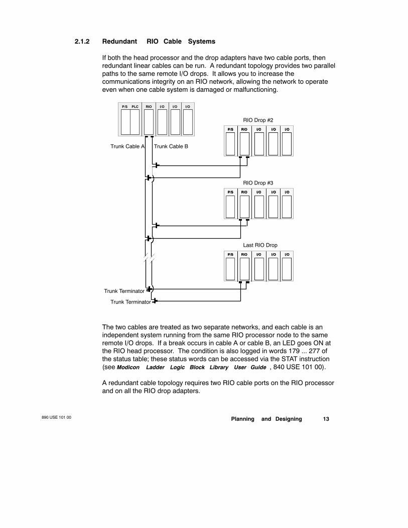
2.1.2 Redundant RIO Cable Systems
If both the head processor and the drop adapters have two cable ports, thenredundant linear cables can be run. A redundant topology provides two parallelpaths to the same remote I/O drops. It allows you to increase thecommunications integrity on an RIO network, allowing the network to operateeven when one cable system is damaged or malfunctioning.
Trunk Cable BTrunk Cable A
PLC RIO I/O I/O I/OP/S
RIO Drop #2
RIOP/SP/S I/OI/O I/OI/O I/OI/ORIO
RIO Drop #3
RIOP/SP/S I/OI/O I/OI/O I/OI/ORIO
Last RIO Drop
RIOP/SP/S I/OI/O I/OI/O I/OI/ORIO
Trunk Terminator
Trunk Terminator
The two cables are treated as two separate networks, and each cable is anindependent system running from the same RIO processor node to the sameremote I/O drops. If a break occurs in cable A or cable B, an LED goes ON atthe RIO head processor. The condition is also logged in words 179 ... 277 ofthe status table; these status words can be accessed via the STAT instruction(see Modicon Ladder Logic Block Library User Guide , 840 USE 101 00).
A redundant cable topology requires two RIO cable ports on the RIO processorand on all the RIO drop adapters.

890 USE 101 0014 Planning and Designing
2.1.3 Dual Cable Systems
If your RIO processor has two cable ports, then two linear cables can be runalong separate routes to different sets of remote drops. A dual cable systemcan be used to extend the total length of the cable system. This topology allowsyou to use the full dynamic range in both directions, thus allowing the cablesystem’s total length to be extended. This topology requires a dual cable port atthe RIO processor and a single cable port at each of the RIO drop adapters.
Trunk Cable B
Trunk Cable A
PLC RIO I/O I/O I/OP/S
Drop #1 on B
RIOP/SP/S I/OI/O I/OI/O I/OI/ORIO
Last Drop on BRIOP/S I/O I/O I/O
Drop #1 on A
RIOP/SP/S I/OI/O I/OI/O I/OI/ORIO
Last Drop on A
RIOP/S I/O I/O I/O
Trunk Terminator
Trunk Terminator
The lengths of the trunk cables and the number of drops from each do not needto be balanced in a dual cable system. In most respects, the two lines can beinstalled as if they were two independent cable systems, with two specialconsiderations:
V The total number of drops on both lines must not exceed the maximumnumber of drops supported by the PLC
V Each drop on the two trunks must have a unique RIO network address
Note RIO statistics using the STAT block will not provide the true status ofeach drop because the drops will only be attached to one of the two RIOconnectors at the head processor. Also, an error LED will be ON at the RIOprocessor.

Planning and Designing890 USE 101 00 15
2.2 Hot Standby Cable Topologies (for 984 PLCs)
A Hot Standby (HSBY) system comprises two identically configured PLC heads(with S908 RIO Processors and HSBY option modules) connected via a splitterso that they both support the same cable system. The splitter is used as acombiner. One of the PLCs acts as the primary controller (updated by the RIOnetwork) while the other is the standby controller (updated by the HSBY optionmodule). In the event that the primary PLC fails, control responsibilities areswitched over to the standby device.
Note The Hot Standby capability is supported only in the 984 PLCs. Theprimary and standby heads both use an HSBY option module.
2.2.1 Single-cable Hot Standby Systems
W911-0xx CableSplitter
Primary PLC Standby PLC
Self-terminatingF Adapter (STFA)
STFA
PLC RIO HSBY I/O I/OP/S PLC RIO HSBY I/O I/OP/S
Trunk Cable
Drop Cable
Drop Cable
Drop Cable
Drop Cable Trunk Terminator
Tap
Tap
Tap
Tap
RIO Drop #2
RIO Drop #3
Last RIO Drop
RIO Drop #4
RIOP/SP/S I/OI/O I/OI/O I/OI/O
RIOP/S I/O I/O I/O
RIO
RIOP/SP/S I/OI/O I/OI/O I/OI/ORIO
RIOP/SP/S I/OI/O I/OI/O I/OI/ORIO

890 USE 101 0016 Planning and Designing
2.2.2 Redundant Hot Standby Cable Systems
Using redundant cabling in a Hot Standby system creates a very powerfulsystem with backup both at the controller head-end and along the RIO network.This topology require the use of RIO head processors and drop adapters withtwo RIO cable ports, and it requires the use of two splitters.
Primary PLC Standby PLCPLC RIO HSBY I/O I/OP/S PLC RIO HSBY I/O I/OP/S
Last RIO Drop on A
W911-0xx Cable
STFAsSTFAs
First RIO Drop on A
RIOP/SP/S I/OI/O I/OI/O I/OI/ORIO
First RIO Drop on B
RIOP/SP/S I/OI/O I/OI/O I/OI/ORIO
P/SP/S I/O I/O I/ORIO
Last RIO Drop on BP/SP/S I/O I/O I/ORIO
Trunk TerminatorTrunk Terminator
Trunk Cable ATrunk Cable B

Planning and Designing890 USE 101 00 17
2.3 Illegal Coaxial Cable Topologies
Given below are several examples of coaxial cable design topologies that areeither not recommended or not permitted on an RIO network.
2.3.1 Using a Splitter as a Branching Device
Using a single splitter as a branching device on the trunk is permitted, but it isnot recommended. If a splitter is used, the trunk extensions running from itmust be balanced to prevent signal reflections. A time domain reflectometer(TDR) must be used to balance the trunk extensions.
Splitter
TapTap
PLC RIO I/O I/O I/OP/S
RIOP/SP/S I/OI/O I/OI/O I/OI/ORIO RIOP/SP/S I/OI/O I/OI/O I/OI/ORIO
RIOP/SP/S I/OI/O I/OI/O I/OI/ORIO RIOP/SP/S I/OI/O I/OI/O I/OI/ORIO
First RIO Drop (Branch A)
Last RIO Drop (Branch A)
First RIO Drop (Branch B)
Last RIO Drop (Branch B)
Caution The use of more than one splitter as a branching device on anRIO network is never permitted.

890 USE 101 0018 Planning and Designing
2.3.2 Illegal Trunk Cable Termination
Remote drops cannot be connected directly to the trunk cable—i.e., a remotedrop cannot be used to terminate the trunk:
Trunk Cable Legal RIO Drop
PLC RIO I/O I/O I/OP/S
RIOP/SP/S I/OI/O I/OI/O I/OI/ORIO
Legal RIO DropRIOP/SP/S I/OI/O I/OI/O I/OI/ORIO
Illegal RIO Drop
RIOP/SP/S I/OI/O I/OI/O I/OI/ORIO
Tap Tap
All remote drops on an RIO network must be connected to a trunk cable via atap and a drop cable, and the last tap on a trunk cable must be terminated witha 75 Ω Modicon 52-0422-000 Trunk Terminator.
2.3.3 Open Taps
If a tap is inserted on the trunk for future use and does not currently have a dropcable connected to it, it must be terminated with a Modicon 52-0402-000 TapPort Terminator.
Trunk Cable
Drop Cable
Drop CableTrunk Terminator
Tap
Tap
Tap
RIO Drop #2
Last RIO Drop
PLC RIO I/O I/O I/O
RIOP/S I/O I/O I/O
RIOP/SP/S I/OI/O I/OI/O I/OI/ORIO
P/S
Head (with RIO Drop #1)
This open tap mustbe terminated
Planning and Designing890 USE 101 00 19
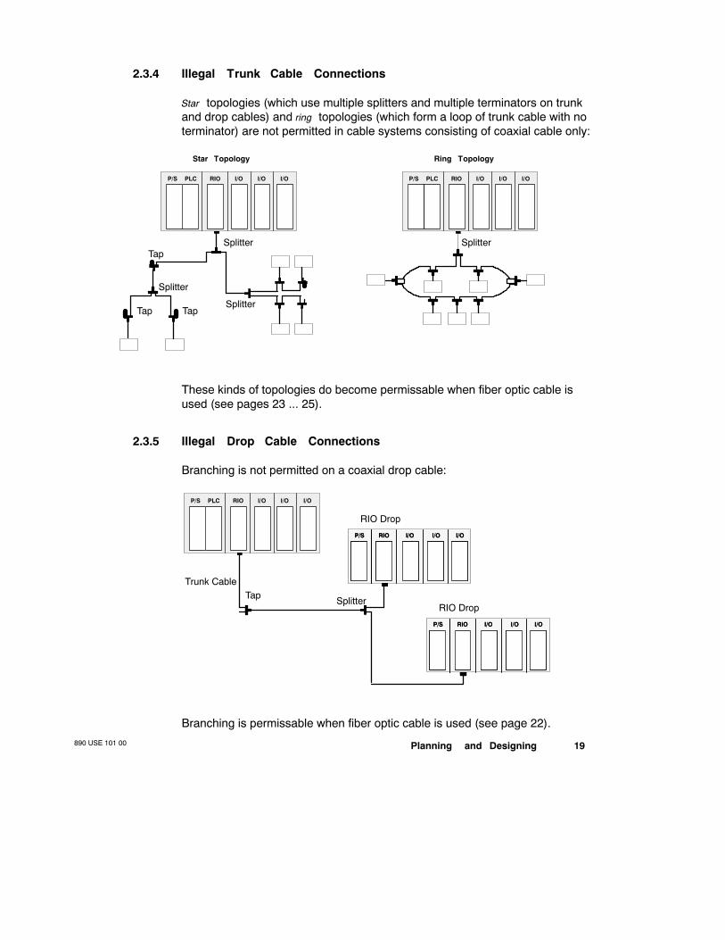
2.3.4 Illegal Trunk Cable Connections
Star topologies (which use multiple splitters and multiple terminators on trunkand drop cables) and ring topologies (which form a loop of trunk cable with noterminator) are not permitted in cable systems consisting of coaxial cable only:
Star Topology Ring Topology
Splitter
Splitter
Splitter
Tap
PLC RIO I/O I/O I/OP/S
Tap Tap
PLC RIO I/O I/O I/OP/S
Splitter
These kinds of topologies do become permissable when fiber optic cable isused (see pages 23 ... 25).
2.3.5 Illegal Drop Cable Connections
Branching is not permitted on a coaxial drop cable:
Trunk Cable
Splitter
RIO Drop
Tap
PLC RIO I/O I/O I/OP/S
RIOP/SP/S I/OI/O I/OI/O I/OI/ORIO
RIO Drop
RIOP/SP/S I/OI/O I/OI/O I/OI/ORIO
Branching is permissable when fiber optic cable is used (see page 22).
890 USE 101 0020 Planning and Designing
2.4 Using Fiber Optics in an RIO System
490NPR954 Fiber Optic Repeaters can be introduced in an RIO cable topologyto allow you to transition from coaxial to fiber cable then back again to coax atone or more of the remote drops on any RIO network. Fiber optics allow you to:
V Extend the total length of the RIO installation
V Significantly improve the noise immunity characteristics of the installation
V Create topologies that would be illegal if built with coaxial cable alone
Note The coaxial cable running into a fiber optic repeater is a drop cable—i.e., coming off a tap from the trunk cable. The coaxial cable coming out of afiber optic repeater is a trunk cable—i.e., taps must be connected to it tosupport the drops and it must be properly terminated at the end of the run.
The RIO port on a fiber optic repeater has the same electrical specifications andrestrictions as a head RIO processor with a pre-amp—e.g., the RIO signaloutput from the fiber link back onto the coaxial cable has a dynamic range of35 dB.
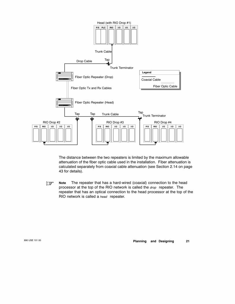
2.4.1 Point-to-point Topology with Fiber Optics
The following illustration shows two segments of RIO coaxial cable connectedpoint-to-point by two 490NRP954 Fiber Optic Repeaters. The fiber link may berun over much longer distances than a coaxial drop cable, and through harshenvironments with noise immunity that cannot be achieved with copper wire.
Planning and Designing890 USE 101 00 21
Trunk Cable
Drop Cable Tap
RIO Drop #2
PLC RIO I/O I/O I/O
RIOP/S I/O I/O I/O
P/S
Head (with RIO Drop #1)
Trunk Cable
Fiber Optic Tx and Rx Cables
Fiber Optic Repeater (Drop)
Fiber Optic Repeater (Head)
Trunk Terminator
RIO Drop #3RIOP/S I/O I/O I/O
RIO Drop #4RIOP/S I/O I/O I/O
Trunk TerminatorTapTapTap
Fiber Optic Cable
Coaxial Cable
Legend
The distance between the two repeaters is limited by the maximum allowableattenuation of the fiber optic cable used in the installation. Fiber attenuation iscalculated separately from coaxial cable attenuation (see Section 2.14 on page43 for details).
Note The repeater that has a hard-wired (coaxial) connection to the headprocessor at the top of the RIO network is called the drop repeater. Therepeater that has an optical connection to the head processor at the top of theRIO network is called a head repeater.
890 USE 101 0022 Planning and Designing
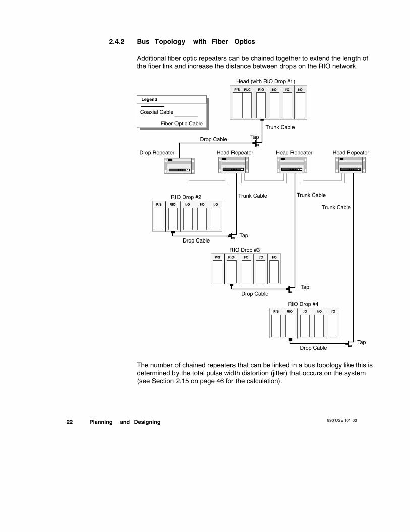
2.4.2 Bus Topology with Fiber Optics
Additional fiber optic repeaters can be chained together to extend the length ofthe fiber link and increase the distance between drops on the RIO network.
Trunk Cable
Drop Cable Tap
PLC RIO I/O I/O I/OP/S
Head (with RIO Drop #1)
Head Repeater
RIO Drop #2RIOP/S I/O I/O I/O
Drop Cable
RIO Drop #3RIOP/S I/O I/O I/O
Drop Cable
RIO Drop #4RIOP/S I/O I/O I/O
Drop Cable
Trunk Cable Trunk Cable
Trunk Cable
Fiber Optic Cable
Coaxial Cable
Legend
Drop Repeater Head Repeater Head Repeater
Tap
Tap
Tap
The number of chained repeaters that can be linked in a bus topology like this isdetermined by the total pulse width distortion (jitter) that occurs on the system(see Section 2.15 on page 46 for the calculation).

Planning and Designing890 USE 101 00 23
2.4.3 Star and Tree Topologies with Fiber Optics
Star and tree topologies, which cannot be established with coaxial cable alone(see page 19), can be built legally using fiber optic repeaters. The followingtree topology is legal on an RIO fiber optic link:
RIO Drop #2RIOP/S I/O I/O I/O
PLC RIO I/O I/O I/OP/S
Head (with RIO Drop #1)
RIO Drop #3RIOP/S I/O I/O I/O
RIO Drop #4RIOP/S I/O I/O I/O
Fiber Optic Cable
Coaxial Cable
Legend
Tap
Tap
Tap
Tap
Tap
Tap

890 USE 101 0024 Planning and Designing
Commercially available passive optical star coupler devices can also beintroduced to the optical link to provide added flexibility to the RIO network. Atypical four-port star coupler could be used as follows on an RIO fiber optic link:
RIO Drop #4RIOP/S I/O I/O I/O
PLC RIO I/O I/O I/OP/S
Head (with RIO Drop #1)
Optical Star Coupler
RIO Drop #3RIOP/S I/O I/O I/O
RIO Drop #2RIOP/S I/O I/O I/O
Fiber Optic Cable
Coaxial Cable
Legend
Tap
Tap Tap
Tap
If a passive optical star coupler is used:
V The number of repeaters and the length of each segment of fiber cablemust be calculated separately
V 100/140 µm fiber cable is recommended because of its higher available op-tical power
Planning and Designing890 USE 101 00 25
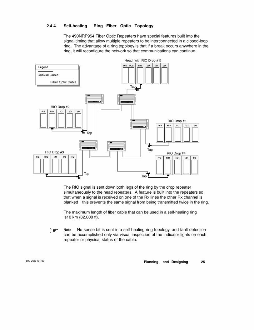
2.4.4 Self-healing Ring Fiber Optic Topology
The 490NRP954 Fiber Optic Repeaters have special features built into thesignal timing that allow multiple repeaters to be interconnected in a closed-loopring. The advantage of a ring topology is that if a break occurs anywhere in thering, it will reconfigure the network so that communications can continue.
PLC RIO I/O I/O I/OP/S
Head (with RIO Drop #1)
RIO Drop #3RIOP/S I/O I/O I/O
RIO Drop #2RIOP/S I/O I/O I/O
RIO Drop #5RIOP/S I/O I/O I/O
RIO Drop #4RIOP/S I/O I/O I/O
Fiber Optic Cable
Coaxial Cable
Legend
Tap
Tap
Tap
TapTap
The RIO signal is sent down both legs of the ring by the drop repeater—simultaneously to the head repeaters. A feature is built into the repeaters sothat when a signal is received on one of the Rx lines the other Rx channel isblanked—this prevents the same signal from being transmitted twice in the ring.
The maximum length of fiber cable that can be used in a self-healing ringis10 km (32,000 ft).
Note No sense bit is sent in a self-healing ring topology, and fault detectioncan be accomplished only via visual inspection of the indicator lights on eachrepeater or physical status of the cable.
890 USE 101 0026 Planning and Designing
2.5 RIO System Design
When designing an RIO cable system, consider:
V Whether you will route one or two cables to the remote drops
V The node limitations—e.g., single-port or dual port, ASCII device support
V The expansion capabilities of the PLCs—i.e., the maximum number of dropssupported
V The number of nodes —head processors and drop adapters
V The locations and the environmental conditions in which these nodes mustoperate
2.5.1 Key Elements in a Cable System Plan
V The cable system must be dedicated to RIO—no other signals or power canbe applied or transmitted on this network
V The attenuation between the head processor (or the last fiber optic repeater,if an optical link is used) and any drop adapter must not exceed 35 dB at1.544 MHz (32 dB the host-based 984 PLCs)
V The maximum length of the trunk cable is determined by the specified atten-uation of the cable type and the number of other cable hardware compo-nents along the network
V The minimum length permitted for a drop cable is 8.5 ft (2.5 m)—a shorterdrop cable can create tap reflections that cause errors in the drop adapter
V The maximum coaxial drop cable length is 164 ft (50 m)—it can be expand-ed with a fiber optic link
V Minimum bend radiuses specified for the trunk and drop cables must not beexceeded
V The cable must be routed away from AC and DC power cables
V The physical cable installation must be well supported, and cable pullstrength must be considered

Planning and Designing890 USE 101 00 27
V Expansion and contraction loops should be put into the cable system to al-low for temperature changes
V Band marked trunk cable is useful for determining tap placement
V The cable system should be single-point grounded within 20 ft of the RIOprocessor—the central ground point may be a tap, a splitter, or a groundblock
Note Document your decisions for the installer and for future reference bymaintenance personnel. Use the guidelines on page to document the system.
2.5.2 Planning for System Expansion
The potential for system expansion should be considered in the initial design. Itis less costly to provide for expansion in the original RIO network plan than toredesign the network later. If your PLC is able to support more RIO drops thanyour current plan requires, consider installing additional taps along the networktrunk cable.
If, for instance, you intend to use a 140 CPU 213 04 Quantum CPU—whichcould support up to 31 remote drops—and your current plan calls for only 10remote drops, you can install as many as 21 extra taps for future expansion.Remember that the unused expansion taps need to be terminated (see Section3.11.1 on page 77).
A minimum spacing of 8.5 ft (2.5 m) must be maintained between taps. Eachunused port in a tap needs to be terminated with a Modicon 52-0402-000 75 ΩTap Port Terminator.
890 USE 101 0028 Planning and Designing
2.6 Choosing Coaxial Cables for an RIO Network
Your choice of cables for an RIO network is very important. Semirigid cableoffers the highest performance trunk cable, but it requires professionalinstallation. Flexible cable is simpler to install but has more signal loss—andthus causes more distance constraints. RG-11 flexible cable is generallyrecommended for use as the trunk, but RG-6 flexible cable may be used as atrunk cable on some small networks. RG-6 is used most often as the dropcable.
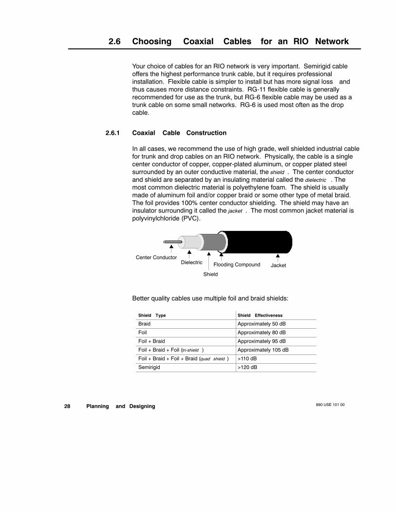
2.6.1 Coaxial Cable Construction
In all cases, we recommend the use of high grade, well shielded industrial cablefor trunk and drop cables on an RIO network. Physically, the cable is a singlecenter conductor of copper, copper-plated aluminum, or copper plated steelsurrounded by an outer conductive material, the shield . The center conductorand shield are separated by an insulating material called the dielectric . Themost common dielectric material is polyethylene foam. The shield is usuallymade of aluminum foil and/or copper braid or some other type of metal braid.The foil provides 100% center conductor shielding. The shield may have aninsulator surrounding it called the jacket . The most common jacket material ispolyvinylchloride (PVC).
JacketFlooding Compound
Shield
DielectricCenter Conductor
Better quality cables use multiple foil and braid shields:
Shield Type Shield Effectiveness
Braid Approximately 50 dB
Foil Approximately 80 dB
Foil + Braid Approximately 95 dB
Foil + Braid + Foil (tri-shield ) Approximately 105 dB
Foil + Braid + Foil + Braid (quad shield ) >110 dB
Semirigid >120 dB

Planning and Designing890 USE 101 00 29
2.6.2 Flexible Cable
Two types of flexible cable can be used in Modicon RIO cable systems—RG-6and RG-11.
RG-6 is a 5/16 in flexible cable with moderate noise immunity and moderatesignal loss (typically 0.48 dB/100 ft at 1.544 MHz, although the loss variesamong manufacturers and cable types). Most applications use RG-6 for dropcables; RG-6 can be used as the trunk cable on small networks.
Modicon 97-5750-000 RG-6 quad shield cable can be ordered on 1000 ft rolls;Modicon also provides pre-assembled RG-6 drop cables in 50 ft (AS-MBII-003)and 140 ft (AS-MBII-004) lengths. Other RG-6 cables for special environmentalrequirements have been approved for use in RIO cable systems—a completelist of all approved RG-6 cables and their performance specifications is providedon pages 54 ... 56.
RG-11 is a 3/8 in flexible cable with good noise immunity and low signal loss(typically 0.24 dB/100 ft at 1.544 MHz). RG-11 cable is suitable for use as trunkcable in most industrial applications and may be used as drop cable in very highnoise environments.
Modicon 97-5951-000 RG-11 quad shield cable can be ordered on 1000 ft rolls.Other RG-11 cables for special environmental requirements have beenapproved for use in RIO cable systems—a complete list of all approved RG-11cables and their performance specifications is provided on pages 57 ... 60.
2.6.3 Semirigid Cable
Semirigid cable construction is similar to that of flexible cable except that it usesa solid aluminum shield for 100% shield coverage. Semirigid cable has highnoise immunity and very low signal loss (typically 0.10 dB/100 ft at 1.544 MHzwith 1/2 in cable), making it ideally suited for the main trunk cable whenmaximum distance and/or high noise immunity is needed. It is not generallyused for drop cable because of its inflexibility.
Semirigid cable is available in sizes that usually range from 1/2 ... 1 in (sizes ator close to 1/2 in are most common). Other sizes are also available. Acomplete list of all approved semirigid cables and their performancespecifications is provided on pages 61 ... 64.
890 USE 101 0030 Planning and Designing
2.7 Coaxial Cable Characteristics
2.7.1 Cable Bend Radius
All cables have a minimum allowable bend radius—i.e., a certain degreebeyond which it cannot be bent—and a minimum support requirement. If thecable is bent more than the allowable bend radius or if the installation is notadequately supported, you can easily damage the center conductor, thedielectric, and cable shield.
This damage can cause signal waveform reflections back into the cable systemand distortions due to cable impedance alterations away from 75 Ω. The endresult will be a series of transmission errors or a nonfunctioning cable system.The situation creates a high voltage standing wave ratio (VSWR) on thesystem—high VSWR causes the transmitted signal to reflect back to the source.
When designing the cable system, consult the manufacturer’s specifications onthe cable bend radius. Design the routing of the cable so that when roundingcorners with cable, the cable is not bent more than the specification and put thisspecification on the design drawings.
2.7.2 Cable Support
Most cable manufacturers recommend that RG-11 and RG-6 cable besupported at least every 50 ft (15 m). Consult the cable manufacturer for moredetail about minimum support requirements for other types of cable.
2.7.3 Cable Pull Strength
Every cable has a maximum allowable pull strength. Any cable that must bepulled through wiring ducts or conduit should have it’s pull strength labeled onthe design drawings. If cable is pulled beyond the maximum allowable limits,the cable will stretch or break causing an impedance mismatch. The stretch orbreak may not be apparent in a visual inspection—e.g., the dielectric inside thecable could become damaged or the center conductor could break. Cable pullstrength ratings can be obtained from the cable manufacturer—they are alsolisted in the cable specifications given on pages 54 ... 64.
2.7.4 Environmental Considerations
Cable components will degrade if subjected to extremes of temperature andhumidity. Consult the manufacturer specifications on the cable components

Planning and Designing890 USE 101 00 31
used in the RIO network to assure they meet the requirements of theapplication.
Provide excess cable in each cable segment of your cable run to allow fortemperature changes. Cable system components will expand and contract as aresult of temperature variations. Several inches of excess cable should beprovided to ensure the cable will not be damaged by temperature changes.Consult the cable manufacturer for the expansion and contractionspecifications.
Cable must also be protected from environments that contain corrosivechemicals, rodents, excessive cable strain and other hazards. Modicon99-0181-000 Sealing Tape may be used to protect connections fromenvironmental problems.

890 USE 101 0032 Planning and Designing
2.8 Electrical Characteristics of Coaxial MediaComponents
The following electrical characteristics must be considered when choosing themedia components for your network cable system. These characteristicsdetermine the maximum length of the cable system and the number of nodespermitted on the network.
2.8.1 Impedance
Impedance is the AC resistance of a cable or network component to a signal.All RIO media components have a characteristic impedance of 75 Ω, with aminimum tolerance of +3 Ω. Media components that can obtain a consistentimpedance as close to 75 Ω as possible yield better performance.
2.8.2 Attenuation
Attenuation is the amount of signal loss through media components. Cable andother media components express attenuation in deciBels (dB). Lowerattenuation of media components allows for higher signal strength and longercable distances throughout the cable system.
RIO networks are limited to a maximum attenuation of 35 dB from the RIO headprocessor (or from the last fiber optic repeater in an optical link) to any dropadapter (32 dB for controllers without pre-amps). Although all mediacomponents have attenuation values, the primary attenuation consideration is inyour coaxial cable selection. A cable’s ability to carry a signal is mostlydetermined by the physical size of the cable. A larger cable can carry a signalfarther than a smaller cable. Here are some rule-of-thumb cable loss figures:
Cable Type Attenuation at 1.544 MHz
1 in semirigid 0.05 dB/100 ft1/2 in semirigid 0.09 dB/100 ft
RG-11 0.24 dB/100 ft
RG-6 0.48 dB/100 ft
Exact attenuation specifications for all approved cable are given on pages 39 ...49.

Planning and Designing890 USE 101 00 33
2.8.3 Return Loss
Return loss is the measurement of reflected signal strength due to impedancemismatch. This measurement is expressed as a number of dB down from theoriginal signal. Components with a higher return loss are better.
If every component of a network were exactly 75 Ω, the return loss would bevery high. In the real world this is impossible. Even the slightest impedancemismatch will cause a portion of the signal to be reflected. This reflection cansubtract from or add to the originally transmitted signal, causing distortion of theoriginal waveform.
Note Return loss problems may be avoided by making all trunk and dropcable purchases from the same manufacturer and the same manufacturingbatch. Ask the manufacturer to pretest the cable for impedance mismatch.
890 USE 101 0034 Planning and Designing
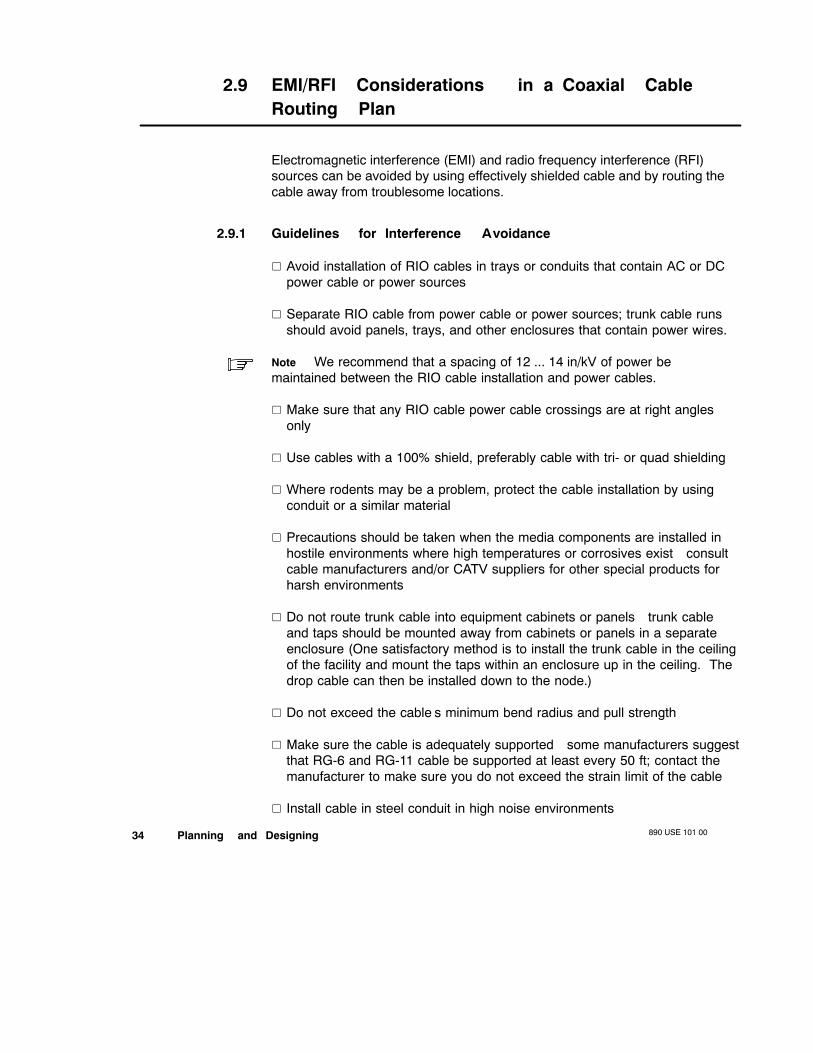
2.9 EMI/RFI Considerations in a Coaxial CableRouting Plan
Electromagnetic interference (EMI) and radio frequency interference (RFI)sources can be avoided by using effectively shielded cable and by routing thecable away from troublesome locations.
2.9.1 Guidelines for Interference Avoidance
V Avoid installation of RIO cables in trays or conduits that contain AC or DCpower cable or power sources
V Separate RIO cable from power cable or power sources; trunk cable runsshould avoid panels, trays, and other enclosures that contain power wires.
Note We recommend that a spacing of 12 ... 14 in/kV of power bemaintained between the RIO cable installation and power cables.
V Make sure that any RIO cable power cable crossings are at right anglesonly
V Use cables with a 100% shield, preferably cable with tri- or quad shielding
V Where rodents may be a problem, protect the cable installation by usingconduit or a similar material
V Precautions should be taken when the media components are installed inhostile environments where high temperatures or corrosives exist—consultcable manufacturers and/or CATV suppliers for other special products forharsh environments
V Do not route trunk cable into equipment cabinets or panels—trunk cableand taps should be mounted away from cabinets or panels in a separateenclosure (One satisfactory method is to install the trunk cable in the ceilingof the facility and mount the taps within an enclosure up in the ceiling. Thedrop cable can then be installed down to the node.)
V Do not exceed the cable’s minimum bend radius and pull strength
V Make sure the cable is adequately supported—some manufacturers suggestthat RG-6 and RG-11 cable be supported at least every 50 ft; contact themanufacturer to make sure you do not exceed the strain limit of the cable
V Install cable in steel conduit in high noise environments
Planning and Designing890 USE 101 00 35
2.10 Tap Connections and Locations
Each tap has three ports—a trunk-in port, a drop cable port, and a trunk-outport; the RIO cables connect to the tap ports via F connectors. The taps comemounted to a plastic block that is used to isolate them from ground. They mustbe surface mounted to a wall or an enclosure. Make sure that no tap in the RIOsystem is grounded or touched by a grounded metallic surface unless it is beingused intentionally as the single grounding point for the entire system.
2.10.1 Using Band Marked Trunk Cable
Improper placement of taps can cause signal reflections and distortion of thesignal waveform. Proper placement will keep these reflections to a minimumand avoid problems with waveform distortion. The preferred method of tapplacement is on cable band markers.
Note If taps are placed too close to each other (or too close to a splitter in aHot Standby system), a cumulative reflection will result. To avoid this problem,install taps at least 8 ft 2 in (2.5 m) away from one another.
Trunk cable should be purchased from the manufacturer with band markersapplied at regular intervals. Intervals will vary based on the propagation of thecable.Modicon RG-11 trunk cable is band marked at 8.86 ft (2.7 m) intervals;RG-6 cable is not band marked. If you are not using Modicon RG-11 for trunkcable, you can instruct your cable manufacturer to apply marker at the requiredintervals. The cost to perform band marking is very small.
The occasional placement of two directly connected taps is possible, but notrecommended. If taps are installed together, no more than two taps should beconnected, and the next multitap connection should be at least 100 ft (30 m)away.
2.10.2 Tap Port Connections
An RG-11 cable can connect directly to a tap port F connector via an Modicon52-0401-000 F Connector installed on the end of the cable (see Section 3.8.3on page 73).
Quad shield RG-6 cable can be connected to a tap port F connector via aModicon MA-0329001 F Connector (see Section 3.8.1 on page 72). Non-quadshield RG-6 cable can be connected to a tap port F connector via a Modicon52-0400-000 F Connector.

890 USE 101 0036 Planning and Designing
Semirigid cable is more difficult to connect to the two (trunk-in and trunk-out) Fconnector ports on the tap. Because there is only a 1 in space between the twoports, you may not be able to fit semirigid connectors directly on both ports. Toavoid this problem, we recommend that you use high quality 90 degree rightangle F adapters such as the Modicon 52-0480-000 Right Angle F Adapter (seeSection 3.9 on page 74).
2.10.3 Optional Tap Enclosure Considerations
Although not required for overall network integrity, you may consider mountingthe taps in separate enclosures away from equipment panels. Potentialperformance improvements include:
V Avoiding panels, trays, and other enclosures that contain power wiring
V Protecting the network from disruptions caused by accidental trunk cabledamage (drop cable damage usually does not disrupt the entire network)
V Performing wiring for future system expansion within panels to avoid rerout-ing the cable later
V Coiling any excess cable within the tap enclosure
Note If excess cable is to be coiled within, the recommended enclosuredimensions are 2 ft (610 mm) long by 2 ft (610 mm) wide by 4 in (102 mm)deep.
Where your overall system design permits it, you may consider locating theenclosures in the ceiling of the facility to further protect against mechanicaldamage to the trunk and taps.
Caution Do not mount a tap within a panel or enclosure that containscontrol equipment—the trunk and tap become susceptible to potentialproblems arising from power source noise, and the cable can bedamaged due to movement by workers or by poor bend radiuses.

Planning and Designing890 USE 101 00 37
2.1 1 Grounding and Surge Suppression
Choose a low impedance earth ground for your cable system, preferably factoryground. Use 10 gauge wire or larger to ground the cable system. Use acommon single-point ground for the cable system and for all equipmentassociated with the system. A separate ground—e.g., a computerground—may actually cause more noise because the RIO nodes will not beconnected to it.
2.1 1.1 Earth Ground
A low impedance earth ground is necessary on RIO cable systems to assuresafety for maintenance personnel and RIO users. The earth ground alsoprovides a path to dissipate noise on the cable system. If the ground is poor ornonexistent, a hazardous shock problem may exist, the cable system will besusceptible to noise, and data transmission errors will occur.
Note All nodes connected to the cable system must be grounded. Under nocircumstances should ungrounded equipment be connected to the cablesystem.
2.1 1.2 Lightning Protection for RIO Cable Systems
Surge suppressors are recommended when a cable system is installedoutdoors or in any environment where lightning protection is required. Thesurge suppressor contains a gas filled tube and two in-line splice connectionpoints. If lightning strikes the cable system or an excessive voltage is presenton the center conductor of the cable, the surge protector will short the centerconductor to ground for the duration of the voltage spike (see page 83).
The surge suppressor must be grounded in order to work properly, but this cancreate a ground loop noise problem. Care must be exercised to assure thatground loops do not cause communications errors. An 8 gauge or largerdiameter green or bare grounding wire is recommended for the surgesuppressor.
890 USE 101 0038 Planning and Designing
2.12 Terminating a Coaxial Cable System
Ideally, all connections on the RIO network are terminated with 75 Ω terminatorsat all times. Depending on the criticality of your application, you may choose todisconnect a drop cable from a drop adapter for short-term maintenance. Thetrunk cable and any unused tap ports must remain terminated at all times.
2.12.1 Terminating the Trunk Cable
To prevent the build-up of a standing wave that can destroy communicationsintegrity on the network, the trunk cable must be terminated at all times with aModicon 52-0422-000 Trunk Terminator (see Section 3.11.2 on page 77). Thetrunk terminator is inserted in the trunk-out port of the last tap on the trunkcable. Do not terminate a trunk cable by connecting it directly to the dropadapter.
2.12.2 Terminating Unused Tap Ports
Unused taps may be installed along the trunk for future system expansion.These taps will not have drop cables connected to them, and they must beterminated at all times with Modicon 52-0402-000 Tap Port Terminators (seeSection 3.11.1 on page 77).
2.12.3 Terminating the Drops
Open connections on a drop cable can subject the network to impedancemismatches and retries. Your application may be able to tolerate these errorsfor short-term maintenance—e.g., swapping a device in the drop—but if youintend to leave the drop cable disconnected from the drop adapter for a longtime or if you are running a critical application elsewhere on the network, youshould put a 75 Ω terminator on the drop cable. You can install a female Fconnector on the drop cable at the time you disconnect it, then install a Modicon52-0402-000 Tap Port Terminator. The drop will always remain terminated aslong as the cable is connected to the RIO drop adapter, even when the device isturned OFF or removed from the I/O rack (exception: the adapter devices andMotion modules listed in Section 1.4.4 ).
Optionally, you may design a mechanical terminator into all the dropcables—such as a Modicon 52-0411-000 Self-terminating F Adapter; this addsup-front cost to your system design but assures you of a completely balancedsystem at all times.

Planning and Designing890 USE 101 00 39
2.13 Designing a Coaxial Cable System to anAttenuation Limit
Attenuation happens naturally as a communication signal passes through taps,splitters, splices, cable, connections, and feed-through terminators. Your goalas designer is to provide successful RIO services while holding the attenuationto a maximum of 35 dB (32 dB in the case of the 984 host-based PLCs) fromthe head processor to any drop adapter on the network.
Note If your cable design exceeds the maximum attenuation limit for yourPLC, transmission errors can occur on the network.
2.13.1 Cable Attenuation
The most important decision the system designer must make with regard tosignal loss is the type of cable used in the system. Many designers usesemirigid cable for the trunk cable in high noise environments or whenmaximum distance is necessary. But the majority of RIO networks use the moreflexible RG-6 and RG-11 cables.
RG-6 can be used as a trunk cable, but its best use is as a drop cable. It canbe used as the trunk on small networks. RG-6 has more attenuation thanRG-11.
2.13.2 Tap Attenuation
All drop adapters must be connected via a tap—never directly to a trunk cable.A direct trunk connection causes a severe impedance mismatch. All RIO tapshave a tap drop loss of 14 dB and an insertion loss of 0.8 dB:
0.8 dB
Drop Cable
TrunkCable
14 dB
Tap Insertion Loss Tap Drop Loss
Tap
Drop Cable
TrunkCable
TrunkCable
TrunkCable
MA-0185-100Tap
MA-0185-100

890 USE 101 0040 Planning and Designing
2.13.3 Calculating Maximum System Attenuation
To calculate maximum attenuation, add all sources of attenuation between theRIO head processor and a drop adapter; the total loss must not exceed 35 dB(32 dB for controllers without pre-amps). The maximum attenuation for thesystem is generally measured from the RIO processor node to the last dropadapter on the network. The last adapter usually represents the maximum lossof the entire cable system. There are exceptions however—adapters near theend of the cable system with long drop cables may have greater attenuation.
Maximum system attenuation at 1.544 MHz can be calculated as follows:
dB loss = TCA + DCA + TDA + (NOS x 6) + (NOT x 0.8)
where
V TCA = the trunk cable attenuation from the head to the end of the trunk
V DCA = the drop cable attenuation, generally at the last drop
V TDA = 14 dB, the tap drop attenuation
V NOS = the number of splitters in the system
V NOT = the number of taps between the last node and the head
Note On a network using dual or redundant trunk cables, calculateattenuation on each separately. Each trunk on a dual or redundant RIOnetwork can handle attenuation up to 35 dB (or 32 dB).
2.13.4 Calculating Attenuation on a Coaxial Network—An Example
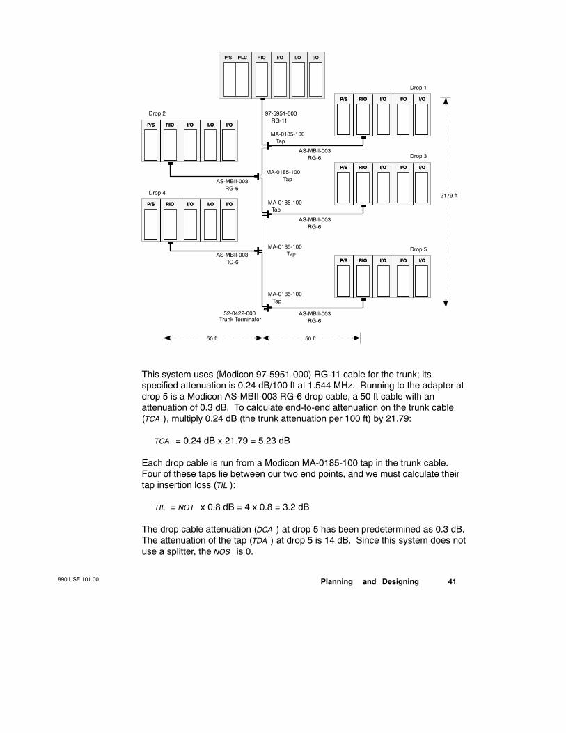
Here is a sample calculation of total attenuation in a five-drop RIO cablesystem. The calculation is made between the head processor and the adapterat drop 5. The distance between the head and the last tap is 2179 ft.
Planning and Designing890 USE 101 00 41
AS-MBII-003
Drop 5
RG-6
AS-MBII-003RG-6
AS-MBII-003RG-6
AS-MBII-003RG-6
AS-MBII-003RG-6
97-5951-000RG-11
50 ft
2179 ft
MA-0185-100Tap
MA-0185-100Tap
MA-0185-100Tap
MA-0185-100Tap
MA-0185-100Tap
52-0422-000Trunk Terminator
PLC RIO I/O I/O I/OP/S
RIOP/SP/S I/OI/O I/OI/O I/OI/ORIO
Drop 3
RIOP/SP/S I/OI/O I/OI/O I/OI/ORIO
Drop 1
RIOP/SP/S I/OI/O I/OI/O I/OI/ORIO
Drop 2
RIOP/SP/S I/OI/O I/OI/O I/OI/ORIO
Drop 4
RIOP/SP/S I/OI/O I/OI/O I/OI/ORIO
50 ft
This system uses (Modicon 97-5951-000) RG-11 cable for the trunk; itsspecified attenuation is 0.24 dB/100 ft at 1.544 MHz. Running to the adapter atdrop 5 is a Modicon AS-MBII-003 RG-6 drop cable, a 50 ft cable with anattenuation of 0.3 dB. To calculate end-to-end attenuation on the trunk cable(TCA ), multiply 0.24 dB (the trunk attenuation per 100 ft) by 21.79:
TCA = 0.24 dB x 21.79 = 5.23 dB
Each drop cable is run from a Modicon MA-0185-100 tap in the trunk cable.Four of these taps lie between our two end points, and we must calculate theirtap insertion loss (TIL ):
TIL = NOT x 0.8 dB = 4 x 0.8 = 3.2 dB
The drop cable attenuation (DCA ) at drop 5 has been predetermined as 0.3 dB.The attenuation of the tap (TDA ) at drop 5 is 14 dB. Since this system does notuse a splitter, the NOS is 0.

890 USE 101 0042 Planning and Designing
Thus, the total attenuation for this RIO network is
5.23 + 0.3 + 14 + 3.2 = 22.73 dB
Proper RIO Cable System Design CharacteristicsThis example shows a properly designed RIO cable system with
V Total attenuation less than 35 dB
V No drop cables longer than 164 feet (50 m)
V Combined cable distance (drop and trunk cables) less than 8400 ft (2560 m)

Planning and Designing890 USE 101 00 43
2.14 Calculating Attenuation on an Optical Path
The attenuation that occurs on an RIO fiber optic link is calculated separatelyfrom attenuation on the coaxial system. Attenuation on an optical link iscalculated based upon an optical power loss budget specified for the type offiber optic cable you are using. The sum of the losses in all components usedin an optical path must not exceed the specified power loss budget for thechosen cable type.
Any of three possible cable core diameters can be used on an optical link:
Core Diameter Attenuation Optical Power Loss Budget
50/125 µm 3.5 dB/km 7.0 dB
62.5/125 µm 3.5 dB/km 11.0 dB
100/140 µm 5.0 dB/km 16.5 dB
The specified power loss budget already takes into account a system margin of3 dB loss at the two ST-type connectors. Only external components such asadditional connectors, star couplers, splices, and actual cable attenuation,should be taken into account in calculating the loss.
2.14.1 Minimum Distance between Repeaters
The transmit optical power of a fiber cable depends greatly on its size. Highoptical power may be required in optical links that use star coupler or splitterdevices, and in these cases the 100/140 µm cable can be used. The use of100/140 µm cable requires that you calculate the minimum distance betweenrepeaters. Minimum distance for 100/140 µm cable is calculated as follows:
Maximum Optical Power Maximum Received SignalCable Attenuation
The optical transmitter in the fiber optic repeater has a maximum optical powerof 4dBm for 100/140 µm cable and a maximum received signal of 10 dBm forany size cable. Thus, the minimum distance between repeaters is:
(4 dBm) (10 dBm) = 1.2 km5 dB/km
Note For long or short distances with minimal distortions, the use of62.5/125 µm cable is the recommended solution. There is no minimumdistance requirement for 50/125 or 62.5/125 µm cable.
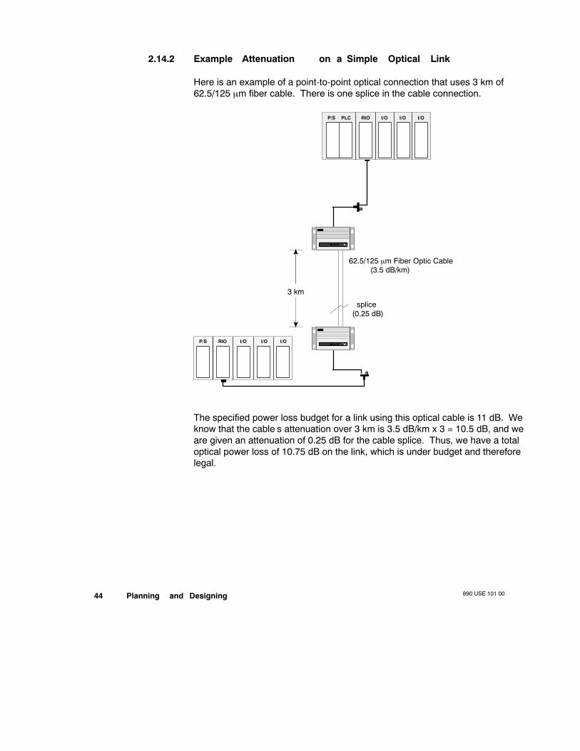
890 USE 101 0044 Planning and Designing
2.14.2 Example—Attenuation on a Simple Optical Link
Here is an example of a point-to-point optical connection that uses 3 km of62.5/125 µm fiber cable. There is one splice in the cable connection.
PLC RIO I/O I/O I/O
RIOP/S I/O I/O I/O
P/S
62.5/125 µm Fiber Optic Cable
splice
(3.5 dB/km)
(0.25 dB)
3 km
The specified power loss budget for a link using this optical cable is 11 dB. Weknow that the cable’s attenuation over 3 km is 3.5 dB/km x 3 = 10.5 dB, and weare given an attenuation of 0.25 dB for the cable splice. Thus, we have a totaloptical power loss of 10.75 dB on the link, which is under budget and thereforelegal.
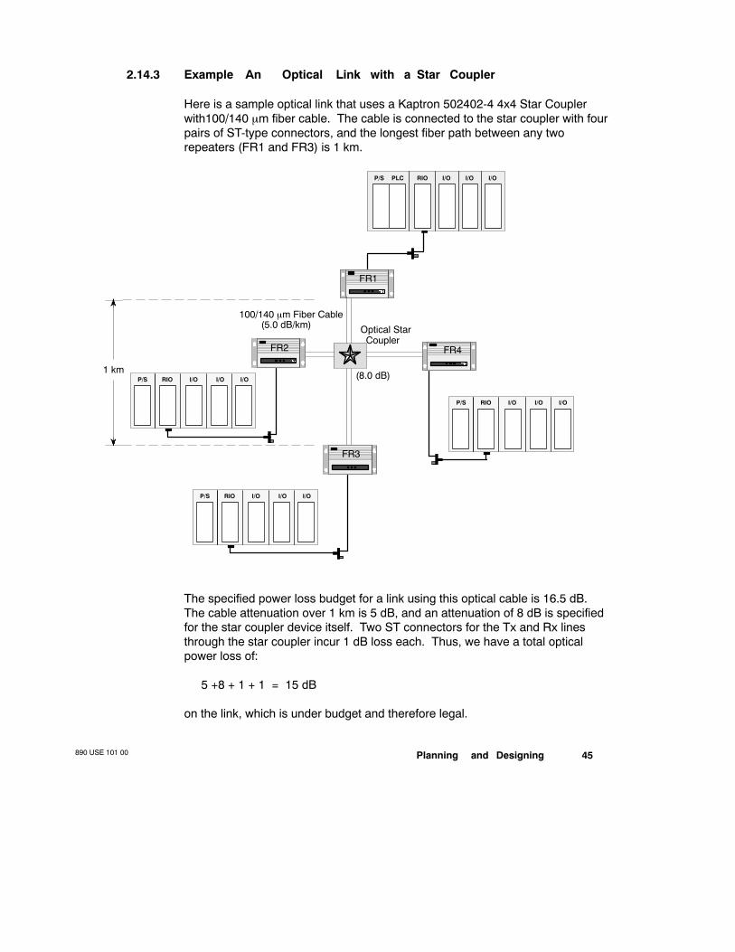
Planning and Designing890 USE 101 00 45
2.14.3 Example—An Optical Link with a Star Coupler
Here is a sample optical link that uses a Kaptron 502402-4 4x4 Star Couplerwith100/140 µm fiber cable. The cable is connected to the star coupler with fourpairs of ST-type connectors, and the longest fiber path between any tworepeaters (FR1 and FR3) is 1 km.
PLC RIO I/O I/O I/OP/S
Optical StarCoupler
RIOP/S I/O I/O I/O
(8.0 dB)1 km
100/140 µm Fiber Cable(5.0 dB/km)
RIOP/S I/O I/O I/O
RIOP/S I/O I/O I/O
FR1
FR2
FR3
FR4
The specified power loss budget for a link using this optical cable is 16.5 dB.The cable attenuation over 1 km is 5 dB, and an attenuation of 8 dB is specifiedfor the star coupler device itself. Two ST connectors for the Tx and Rx linesthrough the star coupler incur 1 dB loss each. Thus, we have a total opticalpower loss of:
5 +8 + 1 + 1 = 15 dB
on the link, which is under budget and therefore legal.

890 USE 101 0046 Planning and Designing
2.15 Pulse W idth Distortion in a Fiber Optic BusTopology
The number of chained repeaters is limited by the system’s total pulse width(jitter) distortions. Shown below is the total amount of jitter contributed by fiberoptic cable for the approved fiber cables for 820 nm with +50 nm of spectralwidth optical signal:
Cable Core Diameter Pulse W idth Distortion (Jitter)
50/125 µm 3.0 ns/km
62.5/125 µm 5.0 ns/km
100/140 µm 7.5 ns/km
The total allowable jitter in the RIO system is limited to 130 ns.
The jitter contributed by the fiber optic repeaters is 10 ns per box. The jittercontributed by the RIO electrical interface is 40 ns (receive-transmit).
The formula to determine the number of chained repeaters (n) is:
n = 130 ns (x * L) ns 40 ns + 110 ns
where:x = jitter specified for the selected cable (from the table above)L = total length of fiber cable in the optical path (in km)
2.15.1 Example—Calculating the Number of Repeaters on a 10 kmOptical Path
In this example, we want to establish a fiber optic bus across a 10 km distance,and we want to know how many repeaters can be used on this bus. The cablebeing used is 62.5/125 µm, which experiences 5 ns/km of jitter. Therefore, thecalculation looks like this:
n = 130 ns (5 * 10) ns 40 ns + 1 = 510 ns
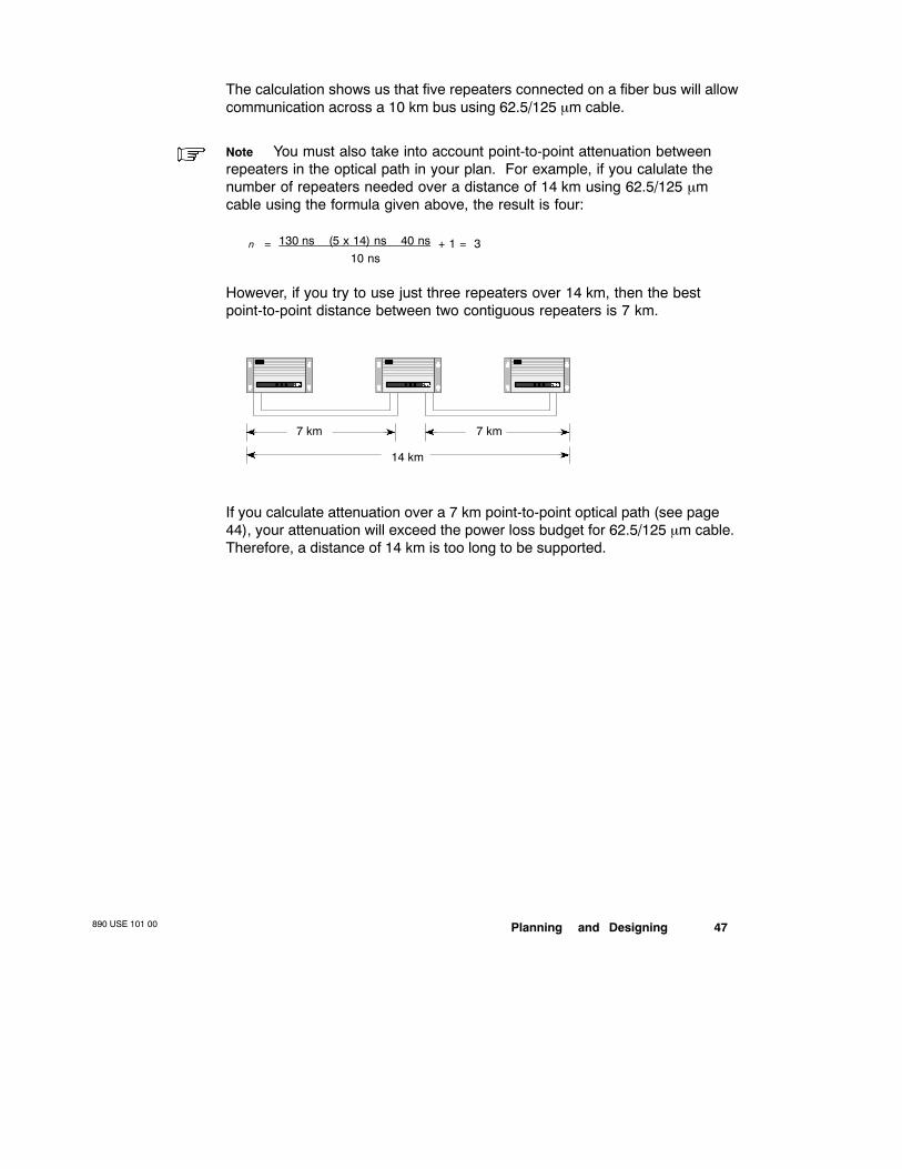
Planning and Designing890 USE 101 00 47
The calculation shows us that five repeaters connected on a fiber bus will allowcommunication across a 10 km bus using 62.5/125 µm cable.
Note You must also take into account point-to-point attenuation betweenrepeaters in the optical path in your plan. For example, if you calulate thenumber of repeaters needed over a distance of 14 km using 62.5/125 µmcable using the formula given above, the result is four:
n = 130 ns (5 x 14) ns 40 ns + 1 = 310 ns
However, if you try to use just three repeaters over 14 km, then the bestpoint-to-point distance between two contiguous repeaters is 7 km.
14 km
7 km 7 km
If you calculate attenuation over a 7 km point-to-point optical path (see page44), your attenuation will exceed the power loss budget for 62.5/125 µm cable.Therefore, a distance of 14 km is too long to be supported.
890 USE 101 0048 Planning and Designing
2.16 Planning RIO Drops
The maximum length for Modicon’s recommended drop cable is 164 ft (50 m).Keeping the drop cable lengths within this limit helps reduce attenuation on thedrop and noise problems on the system. The minimum length for a drop cableis 8.53 ft (2.5 m)—shorter drop cable generates unacceptable signal reflectionsfrom the tap.
RG-6 is the more commonly used drop cable—it has fair noise immunity andgood flexibility. RG-11 cable can also be used—it has better noise immunityand lower loss; RG-11 is recommended in high noise environments.
2.16.1 Connecting the Drop Cable to the Drop Adapter
All drop adapters connect to a coaxial drop cable via either an F connector or aBNC connector:
RIO Adapter RIO Cable Connection Drop Termination
J890/J892-00x BNC connector In the drop adapter
J890/J892-10x* F connector(s)
P890/P892
P451/P453
140 CRA 931 00/ 932 00
* The older J890/J892-00x Adapters use a BNC connector and require a 75 Ωinline terminator in drop cable.
Each drop adapter must be connected separately to a tap port. The tap isolatesthe drop from other drops on the network and also from the trunk cable.Multiple adapters cannot be connected on the same port of a tap. Since anadapter is not directly connected to any other node on the network, mostinstallation and noise-related problems at a drop will not reflect across the entireRIO system.
RIO drop adapters cannot be connected directly to the trunk; they must beconnected to a drop cable that is connected to a tap. Direct connection ofadapters will cause a severe trunk impedance mismatch.
Planning and Designing890 USE 101 00 49
2.16.2 Minimizing Low Receive Signal Level Problems
Some RIO processing devices have a dynamic range of +0 dBmV to +35 dBmVfor receiving signals. Any signal below +0 dBmV cannot be received. Noindication will be given that the signal is too low, but signal levels that varyabove and below this figure will exhibit an increased bit error rate. (This is whythe attenuation between any two nodes must not exceed 32 ... 35 dB.)
Problems related to dynamic range can be difficult to find, and can vary fromday to day. Therefore, a properly designed system should provide a sufficientmargin of error that allows for variances in the signal level—e.g., a receive levelof +1 dBmV or above, attenuation of 32 dB between the RIO head-and theadapter at the most remote drop.
2.16.3 Documenting Your Cable System Design
The cable system should be fully documented. As you work with the installer todetermine a full list of requirements, make a detailed topological drawing of thesystem layout. The detailed plan should include the cable types, all the cablesystem hardware in position, and the complete cable routing plan.
As a starting point, you can document the design in less detail using the fivespecification forms that follow. This initial plan does not give the installer all therouting information, but does give the most important information.

890 USE 101 0050 Planning and Designing
Customer: Network:
Location: Plant:
Revision/Approved by: Date:
Trunk Cable Materials
Trunk Cable Manufacturer:Model #:Quantity Needed:dB Loss (per 100 ft or m):Maximum Pull Strength (lb or kg):Minimum Bend Radius (in or mm):
Trunk Cable Connector Manufacturer:Model #:Quantity Needed:
Trunk Terminator Manufacturer:Model #:Quantity Needed:
Trunk Splice Manufacturer:Model #:Quantity Needed:
Trunk Grounding Block Manufacturer:Model #:Quantity Needed:
Misc. Connector Manufacturer:Model #:Quantity Needed:
Misc. Connector Manufacturer:Model #:Quantity Needed:
Misc. Connector Manufacturer:Model #:Quantity Needed:

Planning and Designing890 USE 101 00 51
Drop Cable and Tap Materials
Drop Cable Manufacturer:Model #:Quantity Needed:dB Loss (per 100 ft or m):Maximum Pull Strength (lb or kg):Minimum Bend Radius (in or mm):
Self-terminating F Adapter Manufacturer:Model #:Quantity Needed:
Drop Cable F Cconnector Manufacturer:Model #:Quantity Needed:
Tap Manufacturer:Model #:Number of Ports:Through Loss (dB):Drop Loss (dB):Quantity Needed:
Tap Manufacturer:Model #:Number of Ports:Insertion Loss (dB):Drop Loss (dB):Quantity Needed:
Tap Port Terminator Manufacturer:Model #:Quantity Needed:
Fiber Optic Cable Manufacturer:Model #:Quantity Needed:dB Loss (per optical link):
ST-type Connector Manufacturer:Model #:Quantity Needed:

890 USE 101 0052 Planning and Designing
Trunk Cable Length
TapNumber
Trunk Length(from head)
Trunk Length(from last tap)
Drop Attenuation(other comments)
Hardware Components890 USE 101 00 53
Chapter 3RIO Network HardwareComponents
V RG-6 Cable
V RG-11 Cable
V Approved Semirigid Cables
V Selecting Fiber Optic Cable
V Hardware Overview
V Tap Specifications
V Splitter Specifications
V F Connectors for Coaxial Cables
V F Adapters for Semirigid Cable
V BNC Connectors and Adapters
V Network Terminators
V Self-terminating F Adapter Options
V Ground Blocks
V Surge Suppressors
V Cable Waterproofing Materials
V Fiber Optic Repeater
V Recommended Materials for a Fiber Optic Installation
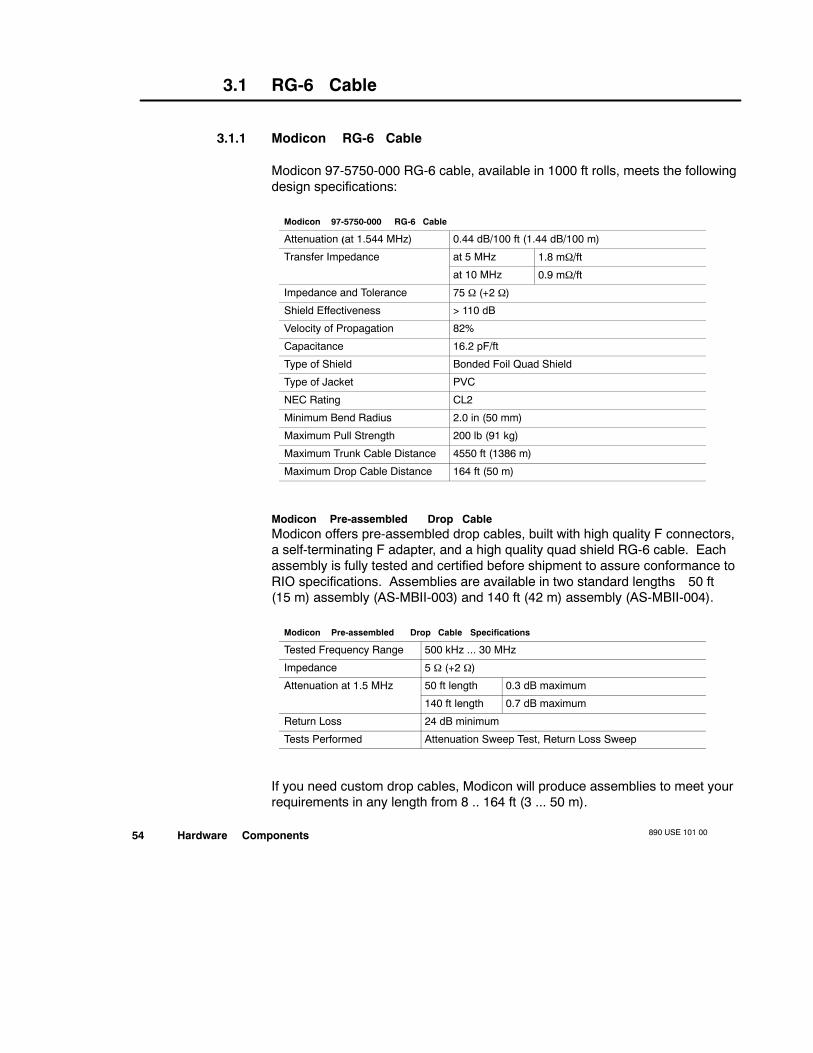
890 USE 101 0054 Hardware Components
3.1 RG-6 Cable
3.1.1 Modicon RG-6 Cable
Modicon 97-5750-000 RG-6 cable, available in 1000 ft rolls, meets the followingdesign specifications:
Modicon 97-5750-000 RG-6 Cable
Attenuation (at 1.544 MHz) 0.44 dB/100 ft (1.44 dB/100 m)
Transfer Impedance at 5 MHz 1.8 mΩ/ft
at 10 MHz 0.9 mΩ/ft
Impedance and Tolerance 75 Ω (+2 Ω)
Shield Effectiveness > 110 dB
Velocity of Propagation 82%
Capacitance 16.2 pF/ft
Type of Shield Bonded Foil Quad Shield
Type of Jacket PVC
NEC Rating CL2
Minimum Bend Radius 2.0 in (50 mm)
Maximum Pull Strength 200 lb (91 kg)
Maximum Trunk Cable Distance 4550 ft (1386 m)
Maximum Drop Cable Distance 164 ft (50 m)
Modicon Pre-assembled Drop CableModicon offers pre-assembled drop cables, built with high quality F connectors,a self-terminating F adapter, and a high quality quad shield RG-6 cable. Eachassembly is fully tested and certified before shipment to assure conformance toRIO specifications. Assemblies are available in two standard lengths—50 ft(15 m) assembly (AS-MBII-003) and 140 ft (42 m) assembly (AS-MBII-004).
Modicon Pre-assembled Drop Cable Specifications
Tested Frequency Range 500 kHz ... 30 MHz
Impedance 5 Ω (+2 Ω)
Attenuation at 1.5 MHz 50 ft length 0.3 dB maximum
140 ft length 0.7 dB maximum
Return Loss 24 dB minimum
Tests Performed Attenuation Sweep Test, Return Loss Sweep
If you need custom drop cables, Modicon will produce assemblies to meet yourrequirements in any length from 8 .. 164 ft (3 ... 50 m).
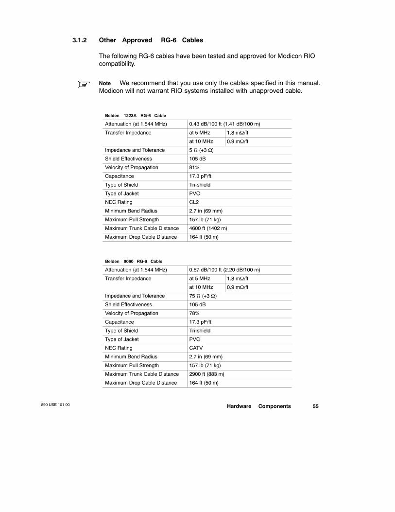
Hardware Components890 USE 101 00 55
3.1.2 Other Approved RG-6 Cables
The following RG-6 cables have been tested and approved for Modicon RIOcompatibility.
Note We recommend that you use only the cables specified in this manual.Modicon will not warrant RIO systems installed with unapproved cable.
Belden 1223A RG-6 Cable
Attenuation (at 1.544 MHz) 0.43 dB/100 ft (1.41 dB/100 m)
Transfer Impedance at 5 MHz 1.8 mΩ/ft
at 10 MHz 0.9 mΩ/ft
Impedance and Tolerance 5 Ω (+3 Ω)
Shield Effectiveness 105 dB
Velocity of Propagation 81%
Capacitance 17.3 pF/ft
Type of Shield Tri-shield
Type of Jacket PVC
NEC Rating CL2
Minimum Bend Radius 2.7 in (69 mm)
Maximum Pull Strength 157 lb (71 kg)
Maximum Trunk Cable Distance 4600 ft (1402 m)
Maximum Drop Cable Distance 164 ft (50 m)
Belden 9060 RG-6 Cable
Attenuation (at 1.544 MHz) 0.67 dB/100 ft (2.20 dB/100 m)
Transfer Impedance at 5 MHz 1.8 mΩ/ft
at 10 MHz 0.9 mΩ/ft
Impedance and Tolerance 75 Ω (+3 Ω)
Shield Effectiveness 105 dB
Velocity of Propagation 78%
Capacitance 17.3 pF/ft
Type of Shield Tri-shield
Type of Jacket PVC
NEC Rating CATV
Minimum Bend Radius 2.7 in (69 mm)
Maximum Pull Strength 157 lb (71 kg)
Maximum Trunk Cable Distance 2900 ft (883 m)
Maximum Drop Cable Distance 164 ft (50 m)
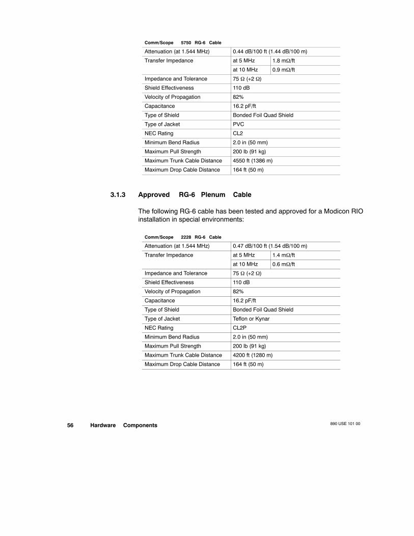
890 USE 101 0056 Hardware Components
Comm/Scope 5750 RG-6 Cable
Attenuation (at 1.544 MHz) 0.44 dB/100 ft (1.44 dB/100 m)
Transfer Impedance at 5 MHz 1.8 mΩ/ft
at 10 MHz 0.9 mΩ/ft
Impedance and Tolerance 75 Ω (+2 Ω)
Shield Effectiveness 110 dB
Velocity of Propagation 82%
Capacitance 16.2 pF/ft
Type of Shield Bonded Foil Quad Shield
Type of Jacket PVC
NEC Rating CL2
Minimum Bend Radius 2.0 in (50 mm)
Maximum Pull Strength 200 lb (91 kg)
Maximum Trunk Cable Distance 4550 ft (1386 m)
Maximum Drop Cable Distance 164 ft (50 m)
3.1.3 Approved RG-6 Plenum Cable
The following RG-6 cable has been tested and approved for a Modicon RIOinstallation in special environments:
Comm/Scope 2228 RG-6 Cable
Attenuation (at 1.544 MHz) 0.47 dB/100 ft (1.54 dB/100 m)
Transfer Impedance at 5 MHz 1.4 mΩ/ft
at 10 MHz 0.6 mΩ/ft
Impedance and Tolerance 75 Ω (+2 Ω)
Shield Effectiveness 110 dB
Velocity of Propagation 82%
Capacitance 16.2 pF/ft
Type of Shield Bonded Foil Quad Shield
Type of Jacket Teflon or Kynar
NEC Rating CL2P
Minimum Bend Radius 2.0 in (50 mm)
Maximum Pull Strength 200 lb (91 kg)
Maximum Trunk Cable Distance 4200 ft (1280 m)
Maximum Drop Cable Distance 164 ft (50 m)
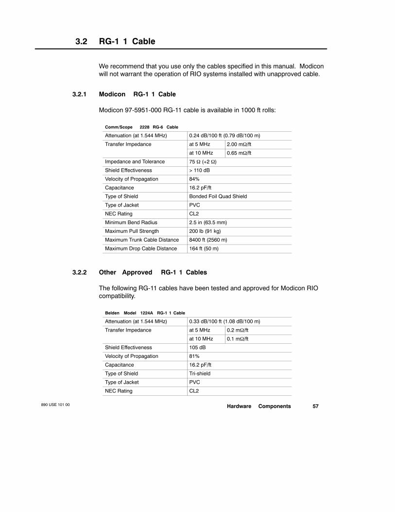
Hardware Components890 USE 101 00 57
3.2 RG-1 1 Cable
We recommend that you use only the cables specified in this manual. Modiconwill not warrant the operation of RIO systems installed with unapproved cable.
3.2.1 Modicon RG-1 1 Cable
Modicon 97-5951-000 RG-11 cable is available in 1000 ft rolls:
Comm/Scope 2228 RG-6 Cable
Attenuation (at 1.544 MHz) 0.24 dB/100 ft (0.79 dB/100 m)
Transfer Impedance at 5 MHz 2.00 mΩ/ft
at 10 MHz 0.65 mΩ/ft
Impedance and Tolerance 75 Ω (+2 Ω)
Shield Effectiveness > 110 dB
Velocity of Propagation 84%
Capacitance 16.2 pF/ft
Type of Shield Bonded Foil Quad Shield
Type of Jacket PVC
NEC Rating CL2
Minimum Bend Radius 2.5 in (63.5 mm)
Maximum Pull Strength 200 lb (91 kg)
Maximum Trunk Cable Distance 8400 ft (2560 m)
Maximum Drop Cable Distance 164 ft (50 m)
3.2.2 Other Approved RG-1 1 Cables
The following RG-11 cables have been tested and approved for Modicon RIOcompatibility.
Belden Model 1224A RG-1 1 Cable
Attenuation (at 1.544 MHz) 0.33 dB/100 ft (1.08 dB/100 m)
Transfer Impedance at 5 MHz 0.2 mΩ/ft
at 10 MHz 0.1 mΩ/ft
Shield Effectiveness 105 dB
Velocity of Propagation 81%
Capacitance 16.2 pF/ft
Type of Shield Tri-shield
Type of Jacket PVC
NEC Rating CL2
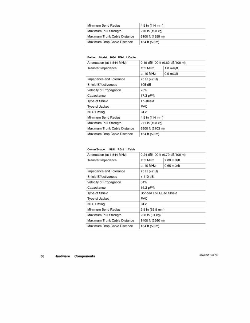
890 USE 101 0058 Hardware Components
Minimum Bend Radius 4.5 in (114 mm)
Maximum Pull Strength 270 lb (123 kg)
Maximum Trunk Cable Distance 6100 ft (1859 m)
Maximum Drop Cable Distance 164 ft (50 m)
Belden Model 9064 RG-1 1 Cable
Attenuation (at 1.544 MHz) 0.19 dB/100 ft (0.62 dB/100 m)
Transfer Impedance at 5 MHz 1.8 mΩ/ft
at 10 MHz 0.9 mΩ/ft
Impedance and Tolerance 75 Ω (+2 Ω)
Shield Effectiveness 105 dB
Velocity of Propagation 78%
Capacitance 17.3 pF/ft
Type of Shield Tri-shield
Type of Jacket PVC
NEC Rating CL2
Minimum Bend Radius 4.5 in (114 mm)
Maximum Pull Strength 271 lb (123 kg)
Maximum Trunk Cable Distance 6900 ft (2103 m)
Maximum Drop Cable Distance 164 ft (50 m)
Comm/Scope 5951 RG-1 1 Cable
Attenuation (at 1.544 MHz) 0.24 dB/100 ft (0.79 dB/100 m)
Transfer Impedance at 5 MHz 2.00 mΩ/ft
at 10 MHz 0.65 mΩ/ft
Impedance and Tolerance 75 Ω (+2 Ω)
Shield Effectiveness > 110 dB
Velocity of Propagation 84%
Capacitance 16.2 pF/ft
Type of Shield Bonded Foil Quad Shield
Type of Jacket PVC
NEC Rating CL2
Minimum Bend Radius 2.5 in (63.5 mm)
Maximum Pull Strength 200 lb (91 kg)
Maximum Trunk Cable Distance 8400 ft (2560 m)
Maximum Drop Cable Distance 164 ft (50 m)

Hardware Components890 USE 101 00 59
Comm/Scope 5950 and 5952 RG-1 1 Cable
Attenuation (at 1.544 MHz) 0.22 dB/100 ft (0.72 dB/100 m)
Transfer Impedance at 5 MHz 2.00 mΩ/ft
at 10 MHz 0.65 mΩ/ft
Impedance and Tolerance 75 Ω (+2 Ω)
Shield Effectiveness > 110 dB
Velocity of Propagation 82%
Capacitance 16.2 pF/ft
Type of Shield Bonded Foil Quad Shield
Type of Jacket PVC (5950) or PE (5952)
NEC Rating CL2
Minimum Bend Radius 2.5 in (63.5 mm)
Maximum Pull Strength 200 lb (91 kg)
Maximum Trunk Cable Distance 6900 ft (2103 m)
Maximum Drop Cable Distance 164 ft (50 m)
Note The Comm/Scope 5952 cable design is similar to Comm/Scope 5950except that it uses a polyethylene jacket rather than PVC. The PE jacketprovides protection against ultraviolet rays and water, and may be used inoutdoor applications.
Comm/Scope 5951 and 5953 RG-1 1 Cable
Attenuation (at 1.544 MHz) 0.22 dB/100 ft (0.72 dB/100 m)
Transfer Impedance at 5 MHz 2.00 mΩ/ft
at 10 MHz 0.65 mΩ/ft
Impedance and Tolerance 75 Ω (+2 Ω)
Shield Effectiveness > 110 dB
Velocity of Propagation 82%
Capacitance 16.2 pF/ft
Type of Shield Bonded Foil Quad Shield
Type of Jacket PVC (5951) or PE (5953)
NEC Rating CL2
Minimum Bend Radius 2.5 in (63.5 mm)
Maximum Pull Strength 200 lb (91 kg)
Maximum Trunk Cable Distance 6900 ft (2103 m)
Maximum Drop Cable Distance 164 ft (50 m)
Note The Comm/Scope 5953 cable design is similar to Comm/Scope 5951except that it uses a polyethylene jacket rather than PVC. The PE jacketprovides protection against ultraviolet rays and water, and may be used inoutdoor applications.
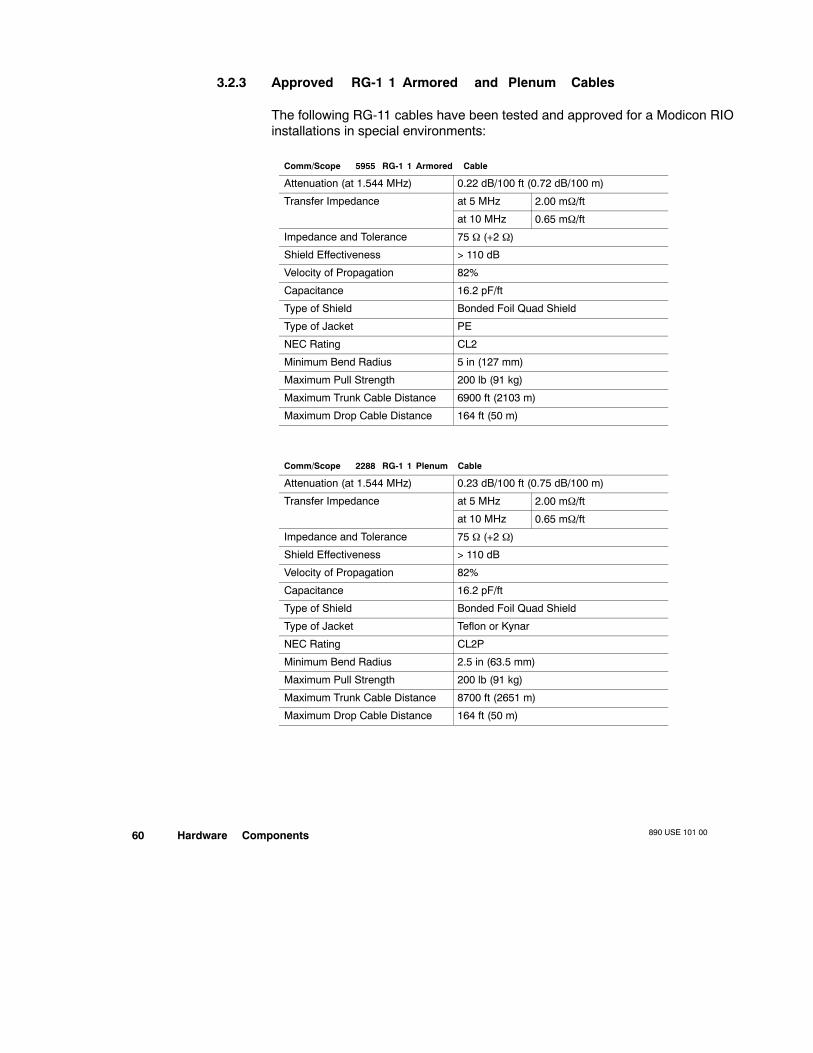
890 USE 101 0060 Hardware Components
3.2.3 Approved RG-1 1 Armored and Plenum Cables
The following RG-11 cables have been tested and approved for a Modicon RIOinstallations in special environments:
Comm/Scope 5955 RG-1 1 Armored Cable
Attenuation (at 1.544 MHz) 0.22 dB/100 ft (0.72 dB/100 m)
Transfer Impedance at 5 MHz 2.00 mΩ/ft
at 10 MHz 0.65 mΩ/ft
Impedance and Tolerance 75 Ω (+2 Ω)
Shield Effectiveness > 110 dB
Velocity of Propagation 82%
Capacitance 16.2 pF/ft
Type of Shield Bonded Foil Quad Shield
Type of Jacket PE
NEC Rating CL2
Minimum Bend Radius 5 in (127 mm)
Maximum Pull Strength 200 lb (91 kg)
Maximum Trunk Cable Distance 6900 ft (2103 m)
Maximum Drop Cable Distance 164 ft (50 m)
Comm/Scope 2288 RG-1 1 Plenum Cable
Attenuation (at 1.544 MHz) 0.23 dB/100 ft (0.75 dB/100 m)
Transfer Impedance at 5 MHz 2.00 mΩ/ft
at 10 MHz 0.65 mΩ/ft
Impedance and Tolerance 75 Ω (+2 Ω)
Shield Effectiveness > 110 dB
Velocity of Propagation 82%
Capacitance 16.2 pF/ft
Type of Shield Bonded Foil Quad Shield
Type of Jacket Teflon or Kynar
NEC Rating CL2P
Minimum Bend Radius 2.5 in (63.5 mm)
Maximum Pull Strength 200 lb (91 kg)
Maximum Trunk Cable Distance 8700 ft (2651 m)
Maximum Drop Cable Distance 164 ft (50 m)

Hardware Components890 USE 101 00 61
3.3 Approved Semirigid Cables
We recommend that you use only the cables specified in this manual. Modiconwill not warrant the operation of RIO systems installed with unapproved cable.
The following semirigid cables have been tested and approved for Modiconcompatibility:
Comm/Scope QR-860-JCA 0.860 in Semirigid Cable
Attenuation (at 1.544 MHz) 0.045 dB/100 ft (0.148 dB/100 m)
Transfer Impedance at 5 MHz 0.1 mΩ/ft
at 10 MHz 0.1 mΩ/ft
Impedance and Tolerance 75 Ω (+2 Ω)
Shield Effectiveness > 120 dB
Velocity of Propagation 88%
Capacitance 15.3 pF/ft
Type of Shield Aluminum Sheath
Type of Jacket PE
NEC Rating CATV
Minimum Bend Radius 7 in (178 mm)
Maximum Pull Strength 450 lb (204 kg)
Maximum Trunk Cable Distance 15,000+ ft (4571+ m)
Comm/Scope QR-540-JCA 0.540 in Semirigid Cable
Attenuation (at 1.544 MHz) 0.087 dB/100 ft (0.285 dB/100 m)
Transfer Impedance at 5 MHz 0.1 mΩ/ft
at 10 MHz 0.1 mΩ/ft
Impedance and Tolerance 75 Ω (+2 Ω)
Shield Effectiveness > 120 dB
Velocity of Propagation 88%
Capacitance 15.3 pF/ft
Type of Shield Aluminum Sheath
Type of Jacket PE
NEC Rating CATV
Minimum Bend Radius 5 in (127 mm)
Maximum Pull Strength 200 lb (91 kg)
Maximum Trunk Cable Distance 15,000+ ft (4571+ m)
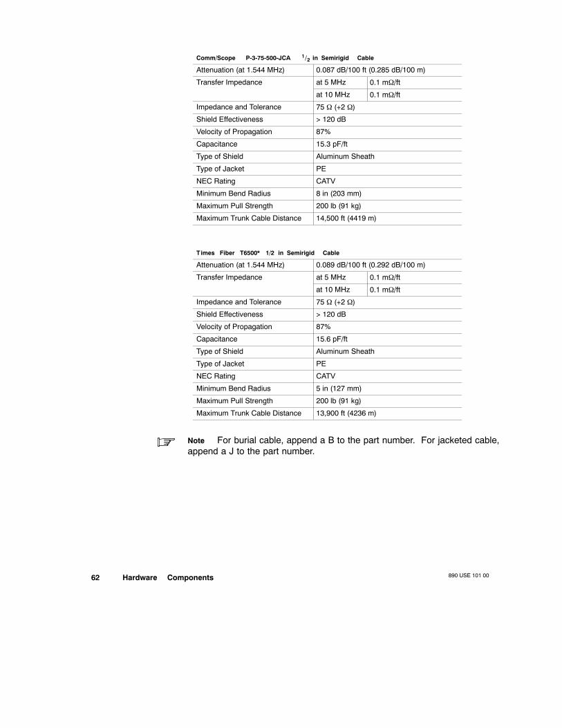
890 USE 101 0062 Hardware Components
Comm/Scope P-3-75-500-JCA 1 /2 in Semirigid Cable
Attenuation (at 1.544 MHz) 0.087 dB/100 ft (0.285 dB/100 m)
Transfer Impedance at 5 MHz 0.1 mΩ/ft
at 10 MHz 0.1 mΩ/ft
Impedance and Tolerance 75 Ω (+2 Ω)
Shield Effectiveness > 120 dB
Velocity of Propagation 87%
Capacitance 15.3 pF/ft
Type of Shield Aluminum Sheath
Type of Jacket PE
NEC Rating CATV
Minimum Bend Radius 8 in (203 mm)
Maximum Pull Strength 200 lb (91 kg)
Maximum Trunk Cable Distance 14,500 ft (4419 m)
Times Fiber T6500* 1/2 in Semirigid Cable
Attenuation (at 1.544 MHz) 0.089 dB/100 ft (0.292 dB/100 m)
Transfer Impedance at 5 MHz 0.1 mΩ/ft
at 10 MHz 0.1 mΩ/ft
Impedance and Tolerance 75 Ω (+2 Ω)
Shield Effectiveness > 120 dB
Velocity of Propagation 87%
Capacitance 15.6 pF/ft
Type of Shield Aluminum Sheath
Type of Jacket PE
NEC Rating CATV
Minimum Bend Radius 5 in (127 mm)
Maximum Pull Strength 200 lb (91 kg)
Maximum Trunk Cable Distance 13,900 ft (4236 m)
Note For burial cable, append a B to the part number. For jacketed cable,append a J to the part number.

Hardware Components890 USE 101 00 63
Times Fiber T6625* .625 in Semirigid Cable
Attenuation (at 1.544 MHz) 0.073 dB/100 ft (0.240 dB/100 m)
Transfer Impedance at 5 MHz 0.1 mΩ/ft
at 10 MHz 0.1 mΩ/ft
Impedance and Tolerance 75 Ω (+2 Ω)
Shield Effectiveness > 120 dB
Velocity of Propagation 87%
Capacitance 15.6 pF/ft
Type of Shield Aluminum Sheath
Type of Jacket PE
NEC Rating CATV
Minimum Bend Radius 7.0 in (178 mm)
Maximum Pull Strength 300 lb (136 kg)
Maximum Trunk Cable Distance 15,000 ft (4571 m)
Note For burial cable, append a B to the part number. For jacketed cable,append a J to the part number.
Times Fiber T6500* 1/2 in Semirigid Cable
Attenuation (at 1.544 MHz) 0.062 dB/100 ft (0.203 dB/100 m)
Transfer Impedance at 5 MHz 0.1 mΩ/ft
at 10 MHz 0.1 mΩ/ft
Impedance and Tolerance 75 Ω (+2 Ω)
Shield Effectiveness > 120 dB
Velocity of Propagation 87%
Capacitance 15.6 pF/ft
Type of Shield Aluminum Sheath
Type of Jacket PE
NEC Rating CATV
Minimum Bend Radius 7.0 in (178 mm)
Maximum Pull Strength 400 lb (181 kg)
Maximum Trunk Cable Distance 15,000 ft (4571 m)
Note For burial cable, append a B to the part number. For jacketed cable,append a J to the part number.
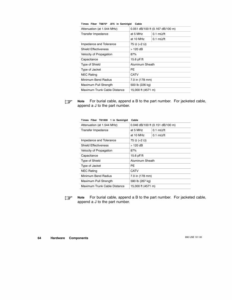
890 USE 101 0064 Hardware Components
Times Fiber T6875* .875 in Semirigid Cable
Attenuation (at 1.544 MHz) 0.051 dB/100 ft (0.167 dB/100 m)
Transfer Impedance at 5 MHz 0.1 mΩ/ft
at 10 MHz 0.1 mΩ/ft
Impedance and Tolerance 75 Ω (+2 Ω)
Shield Effectiveness > 120 dB
Velocity of Propagation 87%
Capacitance 15.6 pF/ft
Type of Shield Aluminum Sheath
Type of Jacket PE
NEC Rating CATV
Minimum Bend Radius 7.0 in (178 mm)
Maximum Pull Strength 500 lb (226 kg)
Maximum Trunk Cable Distance 15,000 ft (4571 m)
Note For burial cable, append a B to the part number. For jacketed cable,append a J to the part number.
Times Fiber T61000 1 in Semirigid Cable
Attenuation (at 1.544 MHz) 0.046 dB/100 ft (0.151 dB/100 m)
Transfer Impedance at 5 MHz 0.1 mΩ/ft
at 10 MHz 0.1 mΩ/ft
Impedance and Tolerance 75 Ω (+2 Ω)
Shield Effectiveness > 120 dB
Velocity of Propagation 87%
Capacitance 15.6 pF/ft
Type of Shield Aluminum Sheath
Type of Jacket PE
NEC Rating CATV
Minimum Bend Radius 7.0 in (178 mm)
Maximum Pull Strength 590 lb (267 kg)
Maximum Trunk Cable Distance 15,000 ft (4571 m)
Note For burial cable, append a B to the part number. For jacketed cable,append a J to the part number.Table 1

Hardware Components890 USE 101 00 65
3.4 Selecting Fiber Optic Cable
If you are using 490NRP954 Fiber Optic Repeaters in your RIO network, thereare several parameters you need to consider, among them cable attenuationand cable bandwidth. Parameters are specified by the cable manufacturer andare based on:
V The wavelength of the optical signal—820 nm in the RIO optical link
V The cable index—use graded-index cable only
V The fiber size—50/125 µm, 62.5/125 µm, or 100/140 µm
For most optical cable links, the use of 62.5/125 µm cable is recommendedbecause of its relatively low loss and signal distortion. In applications wherehigh optical power is required—e.g., to support additional optical devices suchas splitters or star couplers—the 100/140 µm cable should be used (seeSection 2.14 on page 43 for more details on design considerations).
Many cable vendors offer multiple choices for a variety of code ratings:
V From the variety of cables—e.g., AMP or Belden offerings—select the onethat meets the demands of your application. Wherever possible, Modiconrecommends that a multiconductor cable be considered, since it is inexpen-sive; it provides a backup in case a cable gets cut in the process of pullingit; and you will always find uses for the extra path(s), be it for voice, video,other communications, and/or other control applications.
V Most 62.5/125 µm cables are rated at 3.5 dB loss per km. With a multicon-ductor cable, all the pairs usually come with an attenuation specification asmeasured, which may be significantly less than 3.5 dB/km.
890 USE 101 0066 Hardware Components
3.5 Hardware Overview
This chapter provides detailed information about the requirements andavailability of hardware components for the RIO cable system (see the list onpage 67). Many of the components are available directly from Modicon;qualified alternative sources are also given.
3.5.1 Required Cable System Hardware Components
All RIO cable systems require the following hardware components:
V Taps to isolate the individual drop adapters from the rest of the network
V F connectors for making drop cable connections at the taps
V F or BNC connectors for making drop cable connections at the adapter
V Terminators to assure a properly balanced network and to keep unwantedsignals out of the cable system
A splitter is required in a Hot Standby system to connect the primary andstandby PLCs to the trunk cable, and may be used under certain conditions inother RIO cable topologies (see Chapter 2).
3.5.2 Optional Cable System Hardware Components
Depending on the types of cable used in the system and on overall demandsthat will be placed on the network by the application, some of the followinghardware options may be used in your RIO cable system:
V Adapters for converting from F to BNC connectors for making high perfor-mance semirigid trunk cable connections compatible with standard systemhardware
V Self-terminating F adapters or in-line BNC terminators for automatic ter-mination in drop cables should they be disconnected from the drop adapter
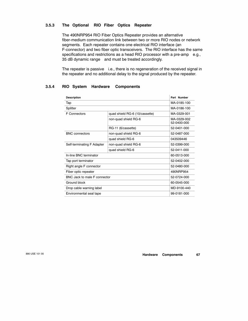
Hardware Components890 USE 101 00 67
3.5.3 The Optional RIO Fiber Optics Repeater
The 490NRP954 RIO Fiber Optics Repeater provides an alternativefiber-medium communication link between two or more RIO nodes or networksegments. Each repeater contains one electrical RIO interface (anF-connector) and two fiber optic transceivers. The RIO interface has the samespecifications and restrictions as a head RIO processor with a pre-amp—e.g.,35 dB dynamic range—and must be treated accordingly.
The repeater is passive—i.e., there is no regeneration of the received signal inthe repeater and no additional delay to the signal produced by the repeater.
3.5.4 RIO System Hardware Components
Description Part Number
Tap MA-0185-100
Splitter MA-0186-100
F Connectors quad shield RG-6 (10/cassette) MA-0329-001
non-quad shield RG-6 MA-0329-00252-0400-000
RG-11 (6/cassette) 52-0401-000
BNC connectors non-quad shield RG-6 52-0487-000
quad shield RG-6 043509446
Self-terminating F Adapter non-quad shield RG-6 52-0399-000
quad shield RG-6 52-0411-000
In-line BNC terminator 60-0513-000
Tap port terminator 52-0402-000
Right angle F connector 52-0480-000
Fiber optic repeater 490NRP954
BNC Jack to male F connector 52-0724-000
Ground block 60-0545-000
Drop cable warning label MD-9100-440
Environmental seal tape 99-0181-000

890 USE 101 0068 Hardware Components
3.6 Tap Specifications
Modicon MA-0185-100 Taps connect the drop cables to the main trunk cableand isolate the RIO drop adapter from the rest of the network. This tap isnondirectional —it allows signals to be propagated in both directions along thetrunk cable. An MA-0185-100 tap has one drop port and two trunk ports.
1.00”
1.00 in2.00 in 3.1 in
.97 in
2.75 in
.650 in
Note Although the trunk ports are labeled IN and OUT, these labels can beignored—i.e., the tap is not directional.
An MA-0185-100 tap is supplied with a plastic isolator on its back. The tapisolates the drop adapter from the trunk cable by 14 dB.
Unused ports on the taps must be terminated—open ports along the networkmust be terminated with a Modicon 52-0402-000 Tap Port Terminator, and thelast (trunk-out) port of the last tap on the network must be terminated with aModicon 52-0422-000 Trunk Terminator (see page 77).

Hardware Components890 USE 101 00 69
MA-0185-100 Tap Specifications
Impedance 75 Ω
Frequency Range 100 kHz ... 30 MHz
Tap Loss 14 dB (+0.5 dB)
Trunk Insertion Loss 0.8 dB maximum
Trunk Return Loss 26 dB minimum
Tap Return Loss -18 dB minimum
Temperature Range 40 ... +60 degrees C
Humidity 95% at 85 degrees C
Sealing RFI/EMI sealed
Interconnections F Connectors torque up to 90 in/lb
Tap Ports Center Contact Grips 24 gauge solid conductor after repeatedinsertions of 16 gauge solid conductor
Tap Ports Connector Threads 3/8-3 2 F Connectors; class 2B-0
Since the trunk ports are 1 in apart, most semirigid connectors do not fit directlyonto the tap. If you are using semirigid cable and its connectors do not fit onthe trunk ports of the tap, use a Modicon 52-0480-000 right-angle F adapter tomake the tap connection.
Note Taps not supplied by Modicon are not supported by Modicon.
Note Older models of the Modicon MA-0185-000 Tap can be used on anRIO network if they are at Revision C.
Note Do not ground a tap unless you are using it specifically as thesingle-point ground for the entire RIO cable system.

890 USE 101 0070 Hardware Components
3.7 Splitter Specifications
The Modicon MA-0186-100 Splitter must used as a signal combiner in a 984Hot Standby cable system; each programmable controller (with an S911 orR911 Hot Standby module in it) has the ability to transmit onto the networkusing the splitter. A single splitter may also be used as a branching device incertain trunk cable topologies, as defined in Chapter 2.
.9 in
1.75 in 1.0 in
2.8 in
.875 inMinimum
.7 in
MA-0186-100 splitters have a minimum return loss of 18 dB on each port. Anyunused port must be terminated. The splitter is installed between two PLCs inthe main trunk cable and has three connectors (ports) on it. Each port isattenuated 6 dB from the other ports. All ports are split equally.
MA-0186-100 Splitter Specifications (for Hot Standby Systems)
Impedance 75 Ω
Frequency Range 100 kHz ... 5 MHz
Trunk Insertion Loss 6.0 dB (+0.5 dB)
Trunk Return Loss 18 dB minimum
Temperature Range 40 ... +60 degrees C
Humidity 95% at 60 degrees C
Sealing RFI/EMI sealed
Interconnections F Connectors torque up to 90 in/lb
Tap Ports Center Contact Grips 24 gauge solid conductor after repeatedinsertions of 16 gauge solid conductor
Tap Ports Connector Threads 3/8-3 2 F Connectors; class 2B-0
Hardware Components890 USE 101 00 71
The input port must connect to the RIO processor, and the two output portsmust connect to the two trunk cable segments. Each output port looses 3.5 dBinsertion loss, referenced to the input port. The isolation between the twooutput ports is a minimum of 28 dB. The high isolation between output portsensures less interference between each trunk segment.
Since the trunk connectors on the splitter are 1 in apart, most semirigidconnectors do not fit. Check with the manufacturer of the semirigid connectorsto ensure they will fit. If they do not fit, use a right angle 90 degree F adapter toconnect the semirigid connector to the splitter.
Note Splitters not supplied by Modicon will not be supported by Modicon.
Note Older model splitters with Modicon part number MA-0186-000 can beused in an RIO network if the revision is at least Revision B.
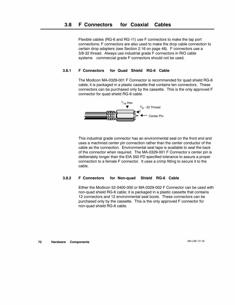
890 USE 101 0072 Hardware Components
3.8 F Connectors for Coaxial Cables
Flexible cables (RG-6 and RG-11) use F connectors to make the tap portconnections; F connectors are also used to make the drop cable connection tocertain drop adapters (see Section 2.16 on page 48). F connectors use a3/8-32 thread. Always use industrial grade F connectors in RIO cablesystems—commercial grade F connectors should not be used.
3.8.1 F Connectors for Quad Shield RG-6 Cable
The Modicon MA-0329-001 F Connector is recommended for quad shield RG-6cable; it is packaged in a plastic cassette that contains ten connectors. Theseconnectors can be purchased only by the cassette. This is the only approved Fconnector for quad shield RG-6 cable.
7/16 Hex3/8 - 32 Thread
Center Pin
This industrial grade connector has an environmental seal on the front end anduses a machined center pin connection rather than the center conductor of thecable as the connection. Environmental seal tape is available to seal the backof the connector when required. The MA-0329-001 F Connector’s center pin isdeliberately longer than the EIA 550 FD specified tolerance to assure a properconnection to a female F connector. It uses a crimp fitting to secure it to thecable.
3.8.2 F Connectors for Non-quad Shield RG-6 Cable
Either the Modicon 52-0400-000 or MA-0329-002 F Connector can be used withnon-quad shield RG-6 cable; it is packaged in a plastic cassette that contains12 connectors and 12 environmental seal boots. These connectors can bepurchased only by the cassette. This is the only approved F connector fornon-quad shield RG-6 cable.

Hardware Components890 USE 101 00 73
7/16 inHex (.440/.435)
End RingFerrule Nut
Mandrel
0.71 in
.130 in(+.010)
3/8 - 32 ThreadI.D. = .345 (+.004)
I.D. = .330 (+.005)
This industrial grade connector has an environmental seal on the back end anduses a boot over the female port to environmentally seal the front of theconnector. It does not have a center pin connection. It is installed with acompression fitting—no crimping is required.
3.8.3 F Connectors for RG-1 1 Cable
The Modicon 52-0401-000 F Connector is recommended for all RG-11 cable; itis packaged in a plastic cassette that contains six connectors and sixenvironmental seal boots. These connectors can be purchased only in thecassette. This is the only approved F connector for RG-11 cable.
5/8 Hex3/8 - 32 Thread
Center Pin isInside Connector
This industrial grade connector fits all types of RG-11 from single-shield to quadshield. It has an environmental seal on the back and uses a boot over thefemale port to environmentally seal the front. It has a center pin connection thatis much more reliable than a center conductor connection and will not damagethe female connector. The 52-0401-000 F Connector is installed with acompression fitting—no crimping is required.

890 USE 101 0074 Hardware Components
3.9 F Adapters for Semirigid Cable
A Modicon 52-0480-000 Right Angle F Adapter is usually needed to attachsemi-rigid trunk cable to the F connector on a tap port; it may also be necessaryat other connection points in order to maintain bend radius tolerance on asemirigid cable.
1.155 in
.032 Diameter
3/8-32 Thread
7/16 in Hex
Accepts18-20 AWG Wire
Modicon has also approved the FF90FM right-angle F adapter manufactured byLRC Electronics and the GFMF/90 right-angle F adapter manufactured byGilbert Engineering.
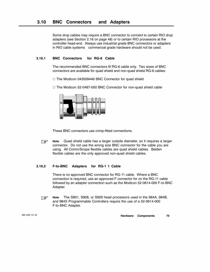
Hardware Components890 USE 101 00 75
3.10 BNC Connectors and Adapters
Some drop cables may require a BNC connector to connect to certain RIO dropadapters (see Section 2.16 on page 48) or to certain RIO processors at thecontroller head-end. Always use industrial grade BNC connectors or adaptersin RIO cable systems—commercial grade hardware should not be used.
3.10.1 BNC Connectors for RG-6 Cable
The recommended BNC connectors fit RG-6 cable only. Two sizes of BNCconnectors are available for quad shield and non-quad shield RG-6 cables:
V The Modicon 043509446 BNC Connector for quad shield
V The Modicon 52-0487-000 BNC Connector for non-quad shield cable
These BNC connectors use crimp-fitted connections.
Note Quad shield cable has a larger outside diameter, so it requires a largerconnector. Do not use the wrong size BNC connector for the cable you areusing. All Comm/Scope flexible cables are quad shield cables. Beldenflexible cables are the only approved non-quad shield cables.
3.10.2 F-to-BNC Adapters for RG-1 1 Cable
There is no approved BNC connector for RG-11 cable. Where a BNCconnection is required, use an approved F connector for on the RG-11 cablefollowed by an adapter connection such as the Modicon 52-0614-000 F-to-BNCAdapter.
Note The S901, S908, or S929 head processors used in the 984A, 984B,and 984X Programmable Controllers require the use of a 52-0614-000F-to-BNC Adapter.

890 USE 101 0076 Hardware Components
.546 inNominalDiameter
.403 in
LRC
34A
009
(+.005)
1.153 in Nominal
.566 in NominalDiameter over Knurl
.437 in Diameter
Female F TerminalAccepts 18-22 AWG
Center Conductor
3/8 - 32 ThreadAccepts Standard
Female F Connector
The 52-0614-000 Adapter permits the F connector on an RG-11 trunk cable tobe attached to the BNC connector on an RIO processor at the networkhead-end or the F connector on an RG-11 drop cable to be connected to aJ810/J812 or J890/J892 drop adapter at the drop.
3.10.3 BNC Jack to Male F Connector
The 52-0724-000 Jack is supplied with the J890/J892-10x RIO drop adapters toterminate cables with BNC connectors.
.032 Diameter
7/16 Hex
3/8 - 32 Thread

Hardware Components890 USE 101 00 77
3.1 1 Network Terminators
All terminators used on the RIO network must have a power handling capabilityof at least 1/4 W. Terminators designed for power-handling, CATV applications,or broadband cable applications cannot be used on an RIO network—they donot work in the RIO frequency range and will cause signal distortion.
3.1 1.1 Tap Port Terminators
All unused drop connectors on taps must be terminated with a standard 75 Ωtap port terminator. The Modicon 52-0402-000 Tap Port Terminator providessuitable termination for this purpose, with a return loss of 22 dB and a frequencyrange from 100 kHz ... 30 MHz.
7/16 Hex
0.12
0.275
0.57
3/8-32 Thread
.025 ∅
3.1 1.2 Trunk Terminators
The trunk cable must be terminated at its tail-end point (in the trunk-out port ofthe last tap in the trunk cable) with a trunk terminator. The Modicon52-0422-000 Trunk Terminator is a precision 75 Ω, 1% tolerance, 14 dBterminating resistor specifically designed for trunk termination. Do not use the52-0402-000 Tap Port Terminator to terminate the trunk cable. The return lossof the 52-0422-000 Trunk Terminator is 40 dB or better at 10 MHz, and itsfrequency range is from 100 kHz ... 30 MHz.
7/16 Hex3/832 Thread
.025∅
.10.58
Chain with Retaining Washer

890 USE 101 0078 Hardware Components
3.1 1.3 BNC In-line Terminators
A Modicon 60-0513-000 BNC In-line Terminator is used to terminate the end ofa drop cable for nodes that require external 75 Ω termination—i.e., the olderJ890/J892-00x Adapters and the Modicon 410 and 3240 Motion products (seethe list in Section 1.4.4).
.575 in
1.95 in
The 60-0513-000 In-line Terminator has two BNC connectors—a female for theincoming drop cable and a male to connect to the drop adapter. It has a returnloss of 20 dB (VSWR 1.2:1), a frequency range from DC ... 300 MHz, and aninsertion loss of 0.03 dB.
3.1 1.4 Self-terminating BNC Adapters for Hot Standby Systems
Modicon 52-0370-000 Self-terminating BNC Adapters are used in 984 HotStandby systems. They allow one Hot Standby PLC to be disconnected fromthe network without causing open-circuit communications errors in the otherPLC. One side of the terminator has a female F connector, and the other sidehas a female BNC connector. Only the BNC side should be disconnected whilethe network is operating. Disconnecting the F connection side will cause animpedance mismatch on the trunk.
Accepts 18 ... 24 AWGSolid Center Conductoror Reducing Pins1.239 in
Standard BNC Interface: AcceptsStandard BNC Plugs with Fixed Termi-nal 1/2-28 Thread 3/8-32 Thread
The 52-0370-000 Self-terminating BNC Adapter has a return loss of 40 dB, afrequency range from 100 kHz ... 30 MHz, and an insertion loss of 0.03 dB.

Hardware Components890 USE 101 00 79
The Modicon 52-0488-000 quad shield BNC Connector and 52-0487-000non-quad shield BNC Connector are not compatible with the self-terminatingBNC adapter because there are not enough threads on the terminator. Aself-terminating F adapter may be used in place of a self-terminating BNCadapter to avoid connector incompatibility.
3.1 1.5 W arning Labels
The self-terminating BNC adapters require warning labels, which promoteproper connection and disconnection practices. Modicon MD-9423-000 HotStandby Processor Warning Labels wrap around the cable near theself-terminating BNC adapters; connect/disconnect instructions are provided onboth sides of the label.

890 USE 101 0080 Hardware Components
3.12 Self-terminating F Adapter Options
As an option for preventing impedance mismatches across the network at alltimes. you could consider installing self-terminating mechanical devices on alldrop cables. The self-terminator may be a self-terminating F or BNC adapter.
3.12.1 Self-terminating F Adapters
A 75 Ω self-terminating F adapter crimps onto the RG-6 drop cable. There aretwo types of self-terminating F adapters:
V A Modicon 52-0411-000 model for quad shield cable
(+.015)
3/8-32 Thread
1.665 in
.194 in(+.002/.001)
Accepts 18 ... 24 AWGCenter Conductor 5/8 in Hex
.520 in.360 in
Hex Crimp
.358 in
V A Modicon 52-0399-000 model for non-quad shield cable
(+.015)
3/8 - 32 Thread
.324 inHex Crimp
1.665 in
.194 in(+.002/.001)
Accepts 18 ... 24 AWGCenter Conductor 5/8 in Hex
.520 in
.339 in(+.002/.001)
Both of these self-terminating F adapters have a return loss of 22 dB, afrequency range from 100 kHz ... 30 MHz, and an insertion loss of 0.03 dB.

Hardware Components890 USE 101 00 81
If you are using RG-11 drop cable, a self-terminating F adapter cannot be used.Since only Belden non-quad shield cable is specified for RIO, use the52-0399-000 self-terminating F adapter only with Belden cable. Plenum cablecannot accept a self-terminating F adapter because of its diameter.
3.12.2 W arning Labels
The self-terminating F adapters require warning labels, which promote properconnection and disconnection practices. Modicon MD-9100-440 Drop CableWarning Labels wrap around the cable near the self-terminating F adapters;connect/ disconnect instructions are provided on both sides of the label.
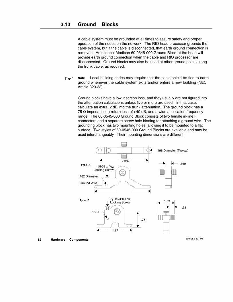
890 USE 101 0082 Hardware Components
3.13 Ground Blocks
A cable system must be grounded at all times to assure safety and properoperation of the nodes on the network. The RIO head processor grounds thecable system, but if the cable is disconnected, that earth ground connection isremoved. An optional Modicon 60-0545-000 Ground Block at the head willprovide earth ground connection when the cable and RIO processor aredisconnected. Ground blocks may also be used at other ground points alongthe trunk cable, as required.
Note Local building codes may require that the cable shield be tied to earthground whenever the cable system exits and/or enters a new building (NECArticle 820-33).
Ground blocks have a low insertion loss, and they usually are not figured intothe attenuation calculations unless five or more are used—in that case,calculate an extra .2 dB into the trunk attenuation. The ground block has a75 Ω impedance, a return loss of >40 dB, and a wide application frequencyrange. The 60-0545-000 Ground Block consists of two female in-line Fconnectors and a separate screw hole binding for attaching a ground wire. Thegrounding block has two mounting holes, allowing it to be mounted to a flatsurface. Two styles of 60-0545-000 Ground Blocks are available and may beused interchangeably. Their mounting dimensions are different:
1.03
.196 Diameter (Typical)
2.332.360
#8-32 x 7/16Locking Screw
.182 Diameter
Ground Wire
.35
.75
1/4 Hex/PhillipsLocking Screw
.15 ∅
Type A
Type B
2.706
1.97
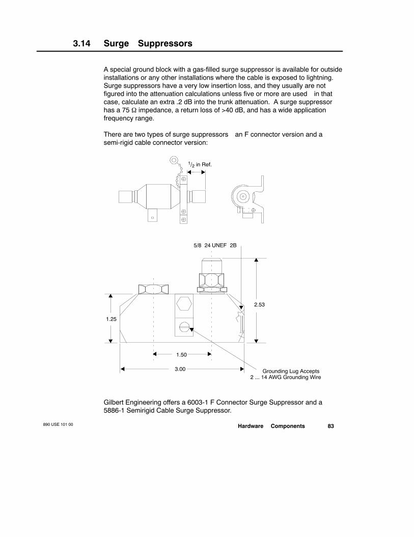
Hardware Components890 USE 101 00 83
3.14 Surge Suppressors
A special ground block with a gas-filled surge suppressor is available for outsideinstallations or any other installations where the cable is exposed to lightning.Surge suppressors have a very low insertion loss, and they usually are notfigured into the attenuation calculations unless five or more are used—in thatcase, calculate an extra .2 dB into the trunk attenuation. A surge suppressorhas a 75 Ω impedance, a return loss of >40 dB, and has a wide applicationfrequency range.
There are two types of surge suppressors—an F connector version and asemi-rigid cable connector version:
1/2 in Ref.
2.53
1.50
3.00
1.25
5/824 UNEF2B
Grounding Lug Accepts2 ... 14 AWG Grounding Wire
Gilbert Engineering offers a 6003-1 F Connector Surge Suppressor and a5886-1 Semirigid Cable Surge Suppressor.

890 USE 101 0084 Hardware Components
3.15 Cable W aterproofing Materials
Several materials are available to seal and waterproof the cable system whenused in a wet, outdoor, or corrosive environment. These materials includesealing boots for F connectors and waterproofing strips to apply overconnections.
Modicon 99-0181-000 Environmental Sealing Tape can be used to sealconnections. Other materials are available from CATV equipmentmanufacturers. The types of material offered vary with each manufacturer.Another source for some of these environmental materials is RaychemCorporation.

Hardware Components890 USE 101 00 85
3.16 Fiber Optic Repeater
The 490NRP954 Fiber Optic Repeater provides communication between two ormore RIO nodes or segments of networks over the fiber optic medium. Eachrepeater contains one electrical RIO interface and two fiber optic transceivers.
1.53 in(39 mm)
Top View
14.08 in (358 mm)12.83 in (326 mm)
11.5 in (292 mm)
5.25 in(133 mm)
8.3 in(211 mm)
Allow 4.0 in (100 mm) Rear Clearance forAccess to Switches, Cables, and Fuse
Fiber Optic Repeater490NRP954
Power CableConnector
PowerSwitchPower Selector
Plug and Fuse
Power CableStrain Relief
Fiber Port 2Rx Tx
Fiber Port 1Tx Rx
RIO Coaxial CableConnection
JP112
24 VDCConnection
+
Chassis Ground Screw
Rear V iew
2.59 in(66 mm)
Shield Configurationjumper switch

890 USE 101 0086 Hardware Components
3.16.1 Repeater Indicator LEDs
The repeater has a set of LEDs located on the top of the unit:
fiber port 1 remote I/Opower OK fiber port 2
V The power OK LED illuminates steadily when the Repeater has normalpower from the AC line or DC source and its internal power supply is oper-ating normally
V The remote I/O port LED lights when a signal is received at the RIO port
V Each fiber port LED lights when a signal is received at the fiber Rx port
If a port LED fails to illuminate, it can indicate a lack of transmitted signal atanother network node. Before replacing a repeater, check the cableconnections on the rear panel for a possible incorrect or loose connection. Alsocheck the indicators on other devices on the signal path to see if the signal lossis external to the repeater.
3.16.2 RIO Shield-to-Chassis Jumper
The RIO cable shield-to-chassis jumper switch on the rear of the repeater isused to specify the repeater’s relationship to chassis ground.
JP1
1
2
neutral
It is shipped in the neutral position—i.e., with the switch midway betweenposition 1 and 2 . The jumper can be placed in either the 1 or 2 position if therepeater is being configured as a head repeater on the optical link such that:
V In the 1 position, the RIO cable shield is isolated from chassis ground by acapacitor—i.e., if low-frequency noise is a problem
V In the 2 position, the RIO cable shield is connected directly to chassisground—i.e., the same ground as the main RIO head processor
V In the neutral position, the repeater is configured as a drop on the opticallink

Hardware Components890 USE 101 00 87
In a point-to-point optical connection, one repeater is always the head and theother is always the drop:
RIO Drop #2
PLC RIO I/O I/O I/O
RIOP/S I/O I/O I/O
P/S
Head (with RIO Drop #1)
Head RepeaterDrop Repeater(Jumper in neutral position) (Jumper in 1 or 2 position)
In an optical bus connection, one repeater is always the drop and all otherrepeaters are heads:
PLC RIO I/O I/O I/OP/S
Head (with RIO Drop #1)
Head RepeaterDrop Repeater
Head Repeater Head Repeater
.
.
.
.
.
.
.
.
.trunk to drop #2 trunk to drop #3 trunk to drop #4
(Jumper in 1 or 2 position) (Jumper in 1 or 2 position) (Jumper in 1 or 2 position)(Jumper in
neutral position)
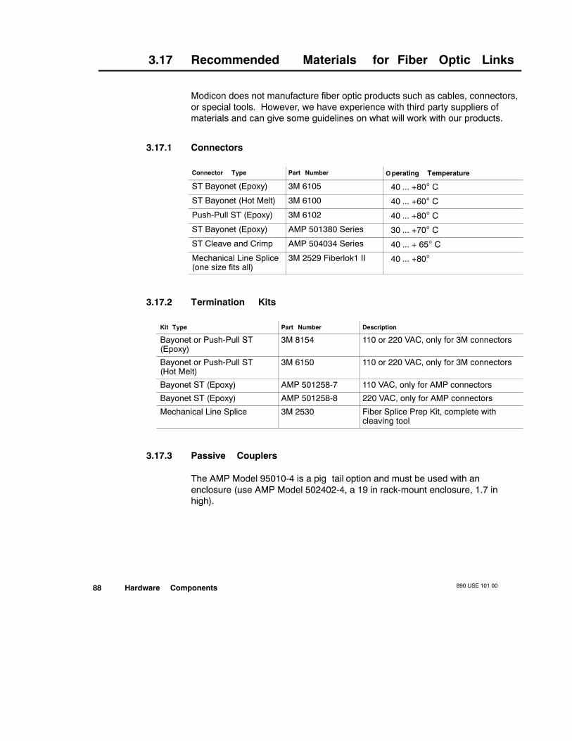
890 USE 101 0088 Hardware Components
3.17 Recommended Materials for Fiber Optic Links
Modicon does not manufacture fiber optic products such as cables, connectors,or special tools. However, we have experience with third party suppliers ofmaterials and can give some guidelines on what will work with our products.
3.17.1 Connectors
Connector Type Part Number O perating Temperature
ST Bayonet (Epoxy) 3M 6105 40 ... +80° C
ST Bayonet (Hot Melt) 3M 6100 40 ... +60° C
Push-Pull ST (Epoxy) 3M 6102 40 ... +80° C
ST Bayonet (Epoxy) AMP 501380 Series 30 ... +70° C
ST Cleave and Crimp AMP 504034 Series 40 ... + 65° C
Mechanical Line Splice(one size fits all)
3M 2529 Fiberlok1 II 40 ... +80°
3.17.2 Termination Kits
Kit Type Part Number Description
Bayonet or Push-Pull ST(Epoxy)
3M 8154 110 or 220 VAC, only for 3M connectors
Bayonet or Push-Pull ST(Hot Melt)
3M 6150 110 or 220 VAC, only for 3M connectors
Bayonet ST (Epoxy) AMP 501258-7 110 VAC, only for AMP connectors
Bayonet ST (Epoxy) AMP 501258-8 220 VAC, only for AMP connectors
Mechanical Line Splice 3M 2530 Fiber Splice Prep Kit, complete withcleaving tool
3.17.3 Passive Couplers
The AMP Model 95010-4 is a pigtail option and must be used with anenclosure (use AMP Model 502402-4, a 19 in rack-mount enclosure, 1.7 inhigh).

Hardware Components890 USE 101 00 89
3.17.4 Other Tools
Product Part Number Description/Use
3M (Photodyne) Optical Source Driv-er
9XT Hand-held optical source driver (re-quires a light source)
3M (Photodyne) Optical Light Source 1700-0850-T 850 nm Light Source, ST Connectorsfor 9XT
3M (Photodyne) Power Meter 17XTA-2041 Hand-held Fiber Optic Power Meter
3M Optical Light Source, 660 nm, vis-ible
7XE-0660-J Use with 9XT to troubleshoot raw fi-ber, requires FC/ST patch cord
3M FC/ST Patch Cord BANAV-FS-0001 Connects FC connector on 7XE to ST
3M Bare Fiber Adapter, ST-compat-ible
8194 Permits use of above source and me-ter to test raw fiber (two required)
Installing an RIO Network890 USE 101 00 91
Chapter 4Installing an RIO Network
V Installation Overview
V RG-6 Cable Connections
V RG-6 Installation Tools
V Preparing RG-6 Cable for a Connector
V Installing F Connectors on Quad Shield RG-6 Cable
V Installing F Connectors on Non-quad Shield RG-6 Cable
V Installing BNC or Self-terminating F Connectors on RG-6
V Making RG-11 F Connections
V The RG-11 Installation Tool
V Preparing an RG-11 Cable for a Connector
V Installing F Connectors on RG-11 Cable
V Providing Line Termination on the Drop Cable
V Connecting/Disconnecting a Drop Cable at a Tap
V Installing Fiber Optic Repeaters
V Terminating the Trunk Cable
V Installing the Ground Point
890 USE 101 0092 Installing an RIO Network
4.1 Installation Overview
This Chapter presents cable preparation and installation procedures for RG-6and RG-11 flexible cables. The connectors and special-purpose installationtools required for these cables are available Modicon.
Modicon provides a common family of compatible connectors for RG-6 andRG-11 cables. A set of installation procedures has been established, with acommon setup procedure and separate finishing procedures for each type ofconnector used.
Note Because of the wide variety of semirigid cables available and becauseModicon does not stock any of these cable types, installation procedures forsemirigid cable are not presented here. If you choose to use semirigid cablein your installation, contact Modicon Customer Service—(508) 975-9479—andyour cable manufacturer for detailed cable installation procedures.
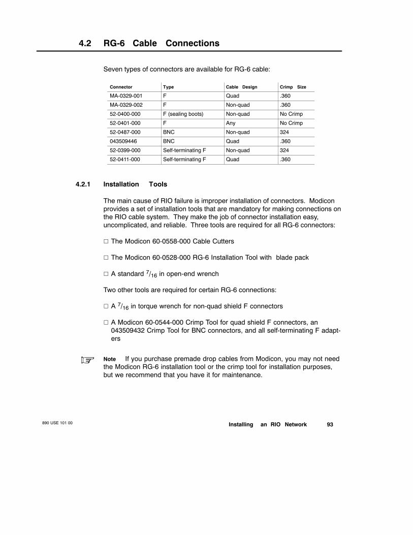
Installing an RIO Network890 USE 101 00 93
4.2 RG-6 Cable Connections
Seven types of connectors are available for RG-6 cable:
Connector Type Cable Design Crimp Size
MA-0329-001 F Quad .360
MA-0329-002 F Non-quad .360
52-0400-000 F (sealing boots) Non-quad No Crimp
52-0401-000 F Any No Crimp
52-0487-000 BNC Non-quad 324
043509446 BNC Quad .360
52-0399-000 Self-terminating F Non-quad 324
52-0411-000 Self-terminating F Quad .360
4.2.1 Installation Tools
The main cause of RIO failure is improper installation of connectors. Modiconprovides a set of installation tools that are mandatory for making connections onthe RIO cable system. They make the job of connector installation easy,uncomplicated, and reliable. Three tools are required for all RG-6 connectors:
V The Modicon 60-0558-000 Cable Cutters
V The Modicon 60-0528-000 RG-6 Installation Tool with blade pack
V A standard 7/16 in open-end wrench
Two other tools are required for certain RG-6 connections:
V A 7/16 in torque wrench for non-quad shield F connectors
V A Modicon 60-0544-000 Crimp Tool for quad shield F connectors, an043509432 Crimp Tool for BNC connectors, and all self-terminating F adapt-ers
Note If you purchase premade drop cables from Modicon, you may not needthe Modicon RG-6 installation tool or the crimp tool for installation purposes,but we recommend that you have it for maintenance.
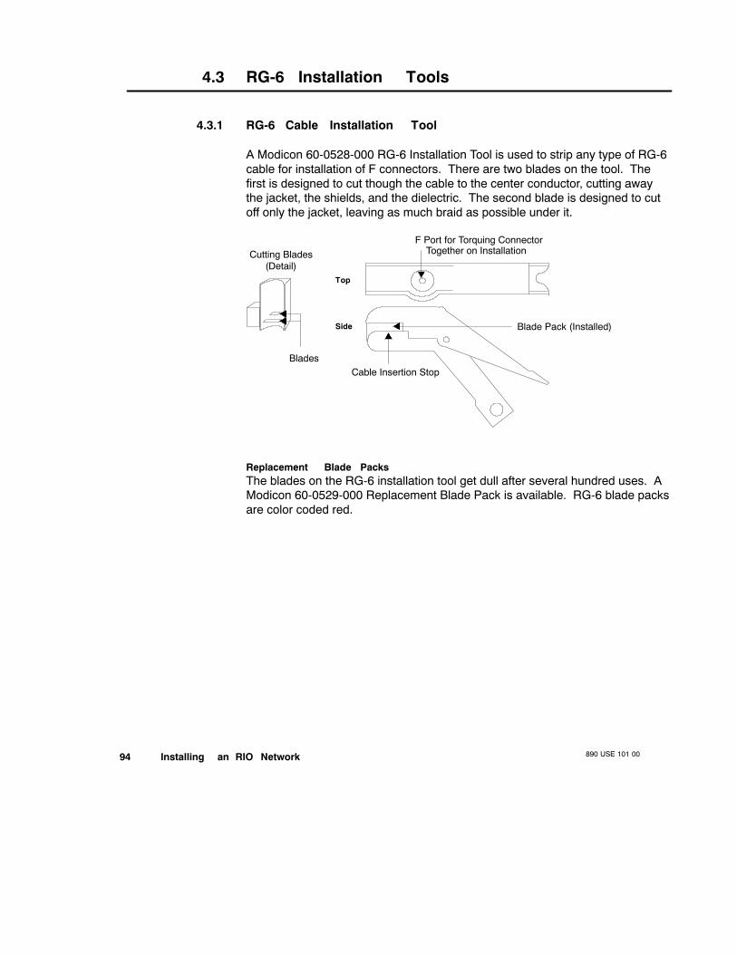
890 USE 101 0094 Installing an RIO Network
4.3 RG-6 Installation Tools
4.3.1 RG-6 Cable Installation Tool
A Modicon 60-0528-000 RG-6 Installation Tool is used to strip any type of RG-6cable for installation of F connectors. There are two blades on the tool. Thefirst is designed to cut though the cable to the center conductor, cutting awaythe jacket, the shields, and the dielectric. The second blade is designed to cutoff only the jacket, leaving as much braid as possible under it.
Top
Side
F Port for Torquing ConnectorTogether on Installation
Blade Pack (Installed)
Cable Insertion Stop
Cutting Blades(Detail)
Blades
Replacement Blade PacksThe blades on the RG-6 installation tool get dull after several hundred uses. AModicon 60-0529-000 Replacement Blade Pack is available. RG-6 blade packsare color coded red.
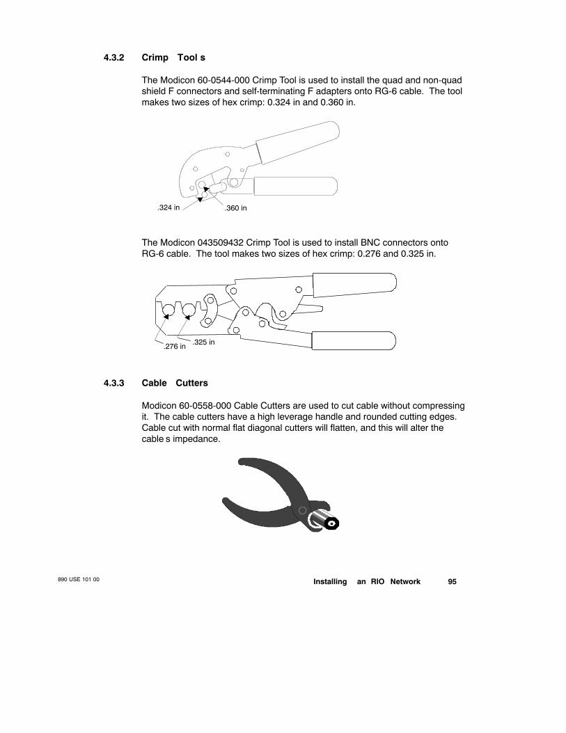
Installing an RIO Network890 USE 101 00 95
4.3.2 Crimp Tool s
The Modicon 60-0544-000 Crimp Tool is used to install the quad and non-quadshield F connectors and self-terminating F adapters onto RG-6 cable. The toolmakes two sizes of hex crimp: 0.324 in and 0.360 in.
.360 in.324 in
The Modicon 043509432 Crimp Tool is used to install BNC connectors ontoRG-6 cable. The tool makes two sizes of hex crimp: 0.276 and 0.325 in.
.276 in .325 in
4.3.3 Cable Cutters
Modicon 60-0558-000 Cable Cutters are used to cut cable without compressingit. The cable cutters have a high leverage handle and rounded cutting edges.Cable cut with normal flat diagonal cutters will flatten, and this will alter thecable’s impedance.

890 USE 101 0096 Installing an RIO Network
4.4 Preparing RG-6 Cable for a Connector
Note If you are using dual or messengered cable, remove the rib beforepreparing the cable.
Step 1 Cut the cable squarely across the end with the 60-0558-000 Cable Cutters.Open the jaws of the 60-0528-000 RG-6 Installation Tool and set the cable inthe V-groove with the cable end placed against the stop.
Cable
Step 2 Release the handle and let the spring hold the tool on the cable. Rotate thestripper clockwise with your index finger on the handle until the tool turnsfreely. Let the spring provide the cutting pressure. The number of turnsdepends on the number of cable shields—dual shields require fewer turnsthan quad shields.
Note Adjust the number of rotations so that the second blade cuts as little ofthe braid as possible. When the crackling noise stops, the first blade has cutthrough the shields. Apply pressure to the tool and rotate it one more time tocut through the remaining dielectric, then pull off the cut cable. This methodusually saves braid.
Push

Installing an RIO Network890 USE 101 00 97
Step 3 If the cable is not fully stripped, squeeze the jaws of the tool together withyour thumb and forefinger. Using light pressure, make one or two revolutionsof the tool around the cable until the tool cuts through the cable jacket.
Squeeze
Squeeze
HoldPull
Step 4 Open the jaws and remove the cable. The dielectric plug and 1/8 in of theouter cable jacket should be cut from the cable. Remove any long braidstrands remaining around the prepared cable end. (Long braid strands mayindicate that a new blade pack is needed.) Remove any dielectric on theexposed center conductor.
1/8 in 5/16 in
Step 5 Fold all of the shield over the jacket except the inner bonded foil. Avoidtearing the inner cable foil.
Braid Folded Over Jacket
Once this cable preparation procedure is completed, you are ready to installRG-6 connectors and/or adapters on the cable.
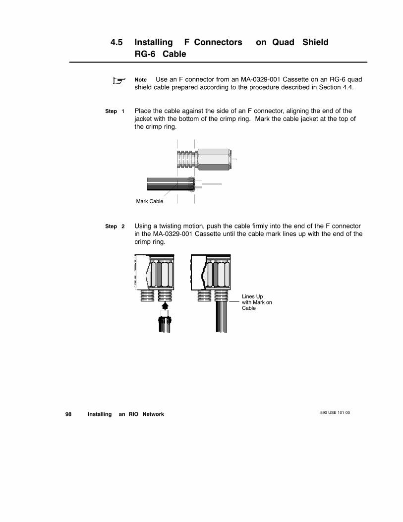
890 USE 101 0098 Installing an RIO Network
4.5 Installing F Connectors on Quad ShieldRG-6 Cable
Note Use an F connector from an MA-0329-001 Cassette on an RG-6 quadshield cable prepared according to the procedure described in Section 4.4.
Step 1 Place the cable against the side of an F connector, aligning the end of thejacket with the bottom of the crimp ring. Mark the cable jacket at the top ofthe crimp ring.
Mark Cable
Step 2 Using a twisting motion, push the cable firmly into the end of the F connectorin the MA-0329-001 Cassette until the cable mark lines up with the end of thecrimp ring.
Lines Upwith Mark onCable

Installing an RIO Network890 USE 101 00 99
Step 3 Remove the F connector by sliding it out the side of the cassette.
Step 4 Align the 60-0544-000 Crimp Tool on the F connector, and apply a .360 incrimp.
Crimp
.360
Step 5 Pull on the F connector to make sure that the crimp is snug—the connectorshould not fall off.
PullSlightly

890 USE 101 00100 Installing an RIO Network
Step 6 Install the F connector onto the cable port of the RIO drop adapter, tap, orother cable hardware device using a 7/16 in open-end wrench.
Note Finger tightening is not sufficient.
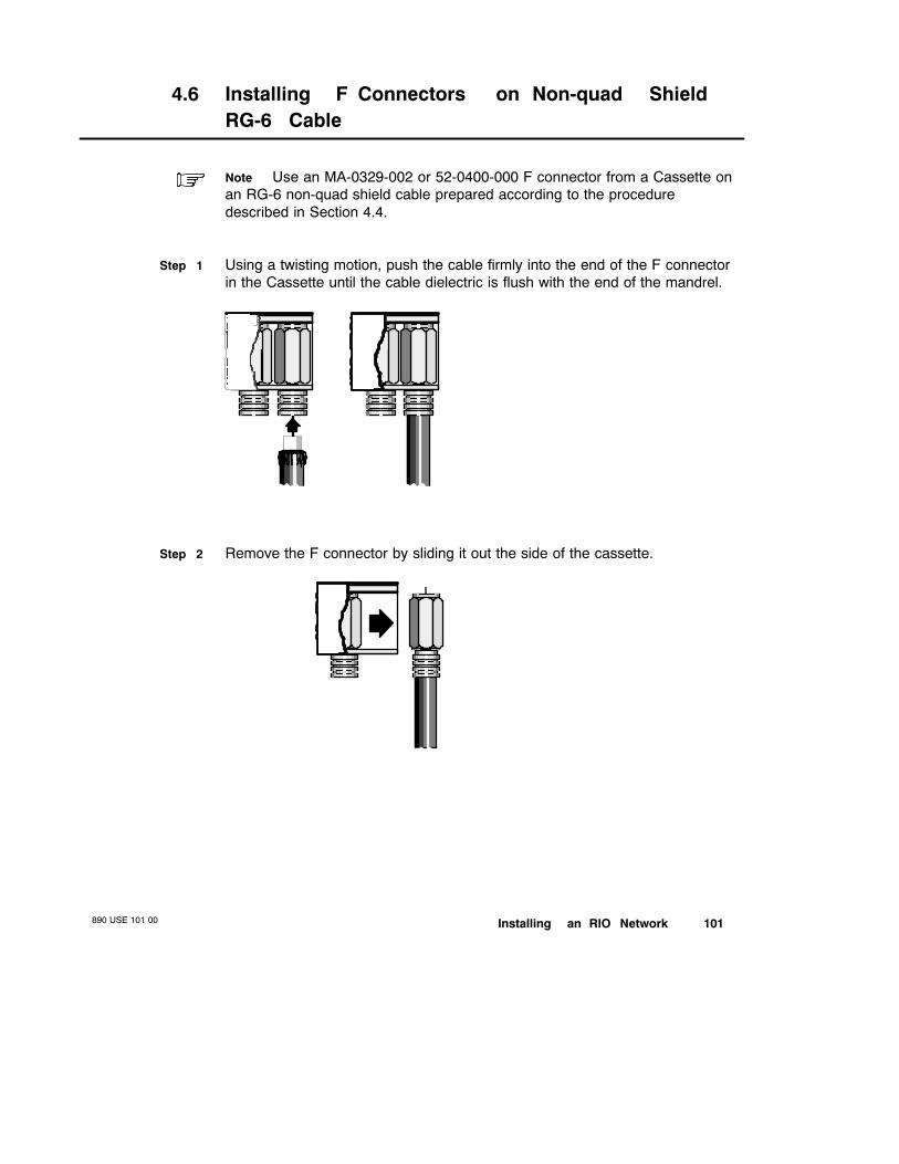
Installing an RIO Network890 USE 101 00 101
4.6 Installing F Connectors on Non-quad ShieldRG-6 Cable
Note Use an MA-0329-002 or 52-0400-000 F connector from a Cassette onan RG-6 non-quad shield cable prepared according to the proceduredescribed in Section 4.4.
Step 1 Using a twisting motion, push the cable firmly into the end of the F connectorin the Cassette until the cable dielectric is flush with the end of the mandrel.
Step 2 Remove the F connector by sliding it out the side of the cassette.

890 USE 101 00102 Installing an RIO Network
Step 3 Visually inspect the cable insertion depth by looking into the end of the Fconnector—the white dielectric should be flush with the end of the mandrel.
Outer Ring of the F Connector
Dielectric
Mandrel
Center Conductor
Step 4 Tighten the F connector nut onto the 60-0528-000 RG-6 Installation Toolconnector with a 7/16 in torque wrench to 47 ... 57 in/lb of torque. Then pull onthe cable to test the integrity of the connection. If the cable pulls out of theconnector, begin the procedure again.
Pull
Step 5 If the connection holds, disconnect the F connector from the tool and install itonto the cable port of the RIO drop adapter, tap, or other cable hardwaredevice using a 7/16 in open-end wrench.
Note Finger tightening is not sufficient.
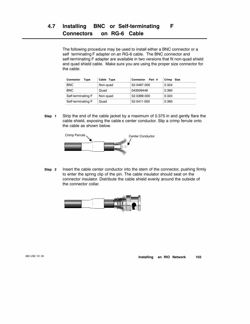
Installing an RIO Network890 USE 101 00 103
4.7 Installing BNC or Self-terminating FConnectors on RG-6 Cable
The following procedure may be used to install either a BNC connector or aselfterminating F adapter on an RG-6 cable. The BNC connector andself-terminating F adapter are available in two versions that fit non-quad shieldand quad shield cable. Make sure you are using the proper size connector forthe cable:
Connector Type Cable Type Connector Part # Crimp Size
BNC Non-quad 52-0487-000 0.324
BNC Quad 043509446 0.360
Self-terminating F Non-quad 52-0399-000 0.324
Self-terminating F Quad 52-0411-000 0.360
Step 1 Strip the end of the cable jacket by a maximum of 0.375 in and gently flare thecable shield, exposing the cable’s center conductor. Slip a crimp ferrule ontothe cable as shown below.
Crimp Ferrule Center Conductor
Step 2 Insert the cable center conductor into the stem of the connector, pushing firmlyto enter the spring clip of the pin. The cable insulator should seat on theconnector insulator. Distribute the cable shield evenly around the outside ofthe connector collar.

890 USE 101 00104 Installing an RIO Network
Step 3 Work the ferrule over the shield braid onto the connector collar. Then crimpwith the 043509432 tool.
Crimp
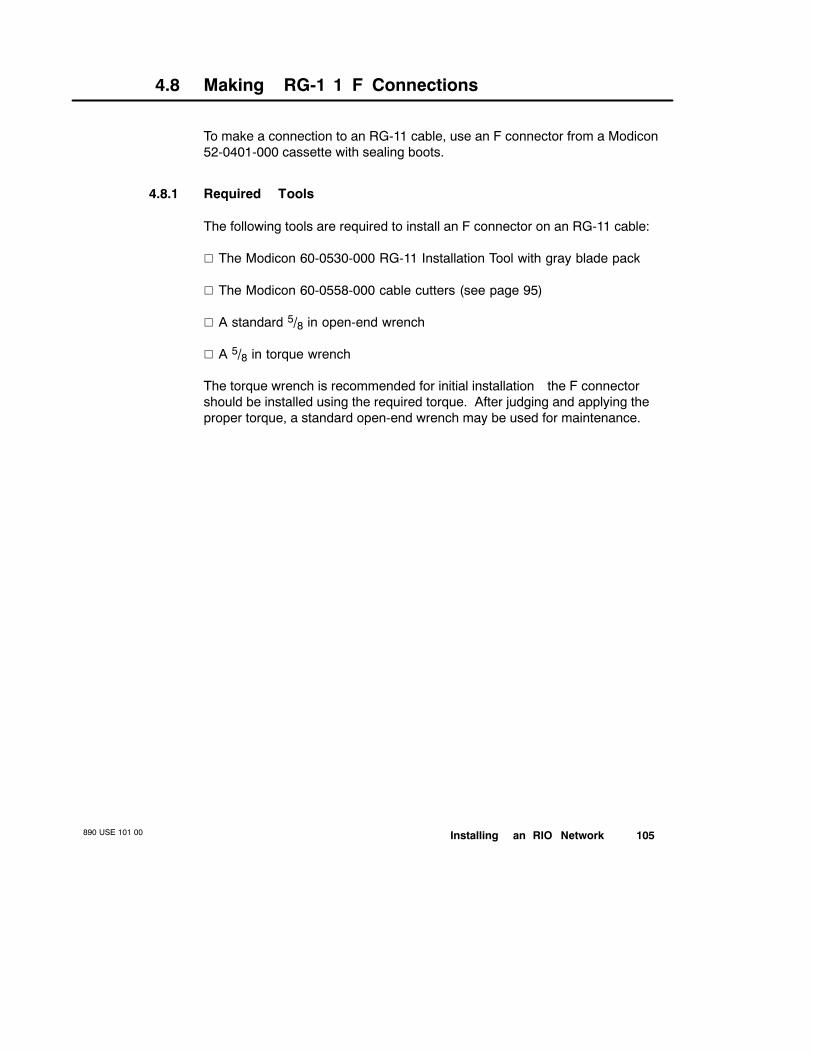
Installing an RIO Network890 USE 101 00 105
4.8 Making RG-1 1 F Connections
To make a connection to an RG-11 cable, use an F connector from a Modicon52-0401-000 cassette with sealing boots.
4.8.1 Required Tools
The following tools are required to install an F connector on an RG-11 cable:
V The Modicon 60-0530-000 RG-11 Installation Tool with gray blade pack
V The Modicon 60-0558-000 cable cutters (see page 95)
V A standard 5/8 in open-end wrench
V A 5/8 in torque wrench
The torque wrench is recommended for initial installation—the F connectorshould be installed using the required torque. After judging and applying theproper torque, a standard open-end wrench may be used for maintenance.

890 USE 101 00106 Installing an RIO Network
4.9 The RG-1 1 Installation Tool
The Modicon 60-0530-000 RG-11 Installation Tool is used to strip any type ofRG-11 cable for installation of F connectors. There are two blades on theinstallation tool. The first is designed to cut though the cable to the centerconductor, cutting away the jacket, the shields, and the dielectric. The secondblade is designed to cut off only the jacket, leaving as much braid as possibleunder it.
Top
Side
F Port for Torquing ConnectorTogether on Installation
Blade Pack (Installed)
Cable Insertion Stop
CuttingBlades(Detail)
Blades
Make adjustments in the number of rotations so that the second blade cuts aslittle of the braid as possible. Usually the first blade has cut through the shieldswhen the crackling noise stops. Apply some pressure to the tool while rotatingit once more after the crackling stops to cut through the remaining dielectric,then pull off the cut cable. This method usually saves as much braid aspossible.
4.9.1 Replacement Blade PacksThe blades on the RG-11 installation tool get dull after several hundred uses. AModicon 60-0531-000 Replacement Blade Pack is available. RG-11 bladepacks are color coded gray.
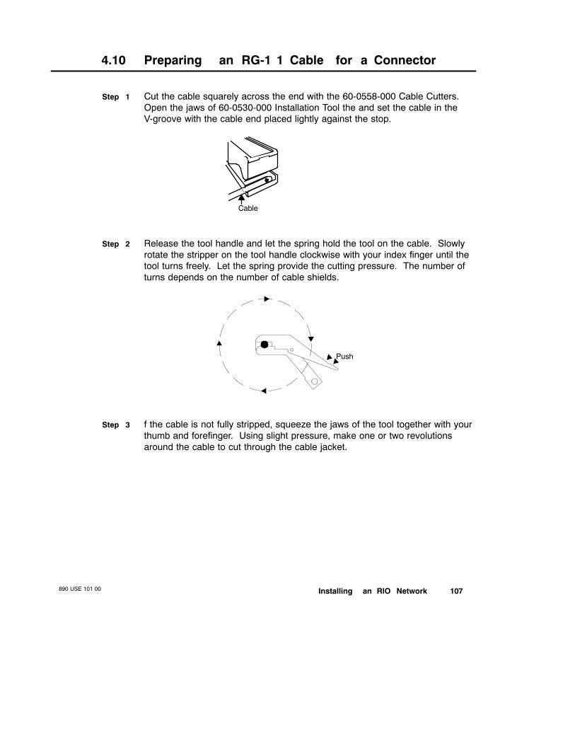
Installing an RIO Network890 USE 101 00 107
4.10 Preparing an RG-1 1 Cable for a Connector
Step 1 Cut the cable squarely across the end with the 60-0558-000 Cable Cutters.Open the jaws of 60-0530-000 Installation Tool the and set the cable in theV-groove with the cable end placed lightly against the stop.
Cable
Step 2 Release the tool handle and let the spring hold the tool on the cable. Slowlyrotate the stripper on the tool handle clockwise with your index finger until thetool turns freely. Let the spring provide the cutting pressure. The number ofturns depends on the number of cable shields.
Push
Step 3 f the cable is not fully stripped, squeeze the jaws of the tool together with yourthumb and forefinger. Using slight pressure, make one or two revolutionsaround the cable to cut through the cable jacket.

890 USE 101 00108 Installing an RIO Network
Step 4 Mark the cable jacket on the side of the tool where the cable exits—this markshows the connector’s insertion depth.
InsertionDepth
Mark Cable Here
Step 5 Open the jaws and remove the cable. Twist off the cable dielectric and jacketby hand. Remove any long braid strands remaining around the preparedcable end. Long braid strands may be an indication that a new blade pack isneeded. Remove any dielectric on the exposed center conductor.
1/8 in 1/4 in
Step 6 Fold all of the braid over the jacket. Avoid tearing the inner foil. To makeinsertion into the connector easier, slightly squeeze the cut end of thefoil-covered dielectric.
Braid Folded over JacketSqueeze Cut End of Foil
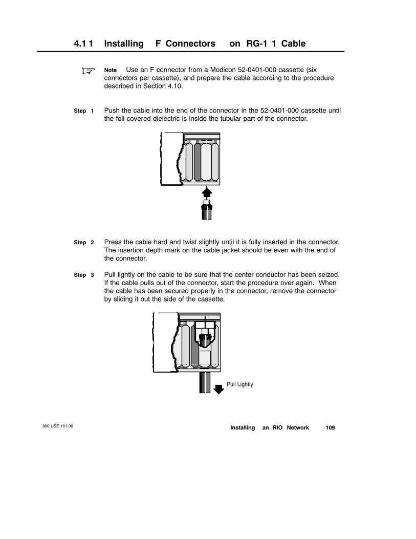
Installing an RIO Network890 USE 101 00 109
4.1 1 Installing F Connectors on RG-1 1 Cable
Note Use an F connector from a Modicon 52-0401-000 cassette (sixconnectors per cassette), and prepare the cable according to the proceduredescribed in Section 4.10.
Step 1 Push the cable into the end of the connector in the 52-0401-000 cassette untilthe foil-covered dielectric is inside the tubular part of the connector.
Step 2 Press the cable hard and twist slightly until it is fully inserted in the connector.The insertion depth mark on the cable jacket should be even with the end ofthe connector.
Step 3 Pull lightly on the cable to be sure that the center conductor has been seized.If the cable pulls out of the connector, start the procedure over again. Whenthe cable has been secured properly in the connector, remove the connectorby sliding it out the side of the cassette.
Pull Lightly
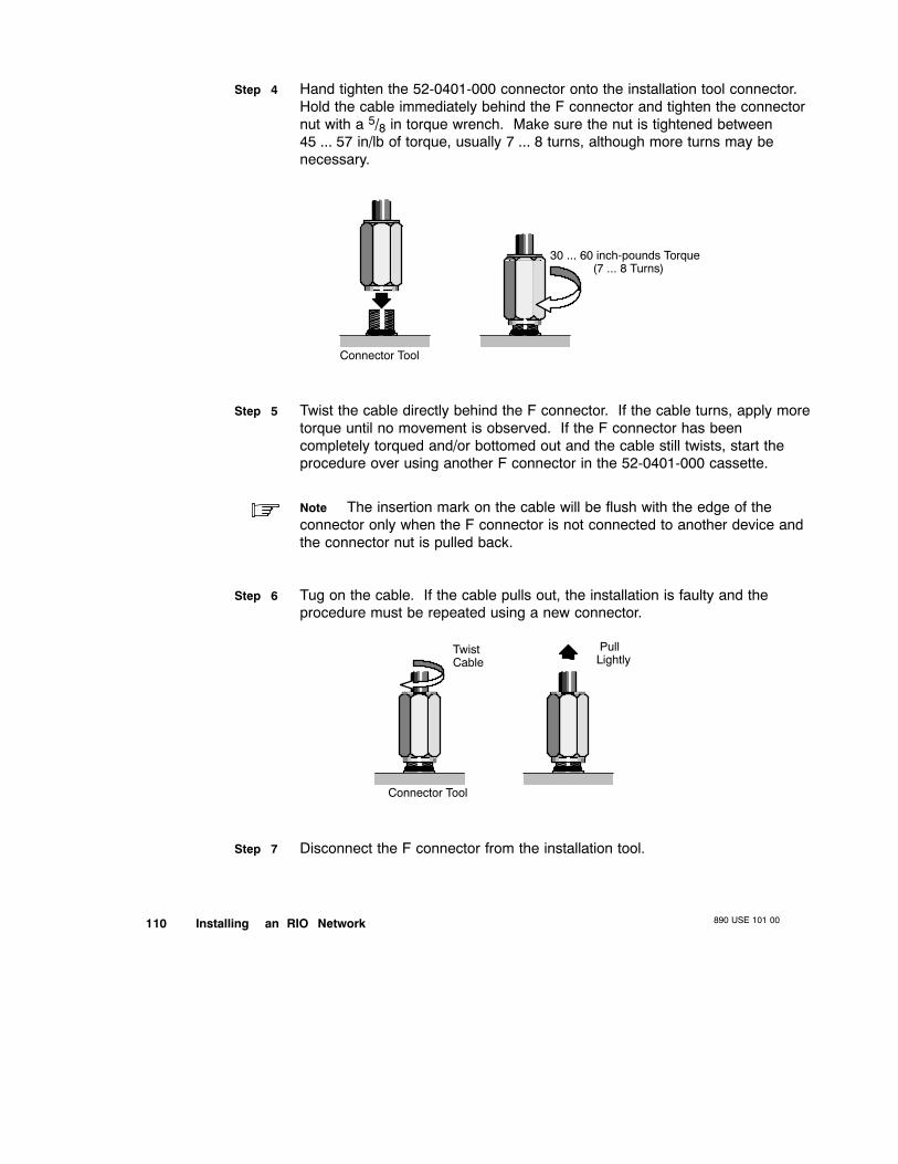
890 USE 101 00110 Installing an RIO Network
Step 4 Hand tighten the 52-0401-000 connector onto the installation tool connector.Hold the cable immediately behind the F connector and tighten the connectornut with a 5/8 in torque wrench. Make sure the nut is tightened between45 ... 57 in/lb of torque, usually 7 ... 8 turns, although more turns may benecessary.
30 ... 60 inch-pounds Torque(7 ... 8 Turns)
Connector Tool
Step 5 Twist the cable directly behind the F connector. If the cable turns, apply moretorque until no movement is observed. If the F connector has beencompletely torqued and/or bottomed out and the cable still twists, start theprocedure over using another F connector in the 52-0401-000 cassette.
Note The insertion mark on the cable will be flush with the edge of theconnector only when the F connector is not connected to another device andthe connector nut is pulled back.
Step 6 Tug on the cable. If the cable pulls out, the installation is faulty and theprocedure must be repeated using a new connector.
Connector Tool
TwistCable
PullLightly
Step 7 Disconnect the F connector from the installation tool.
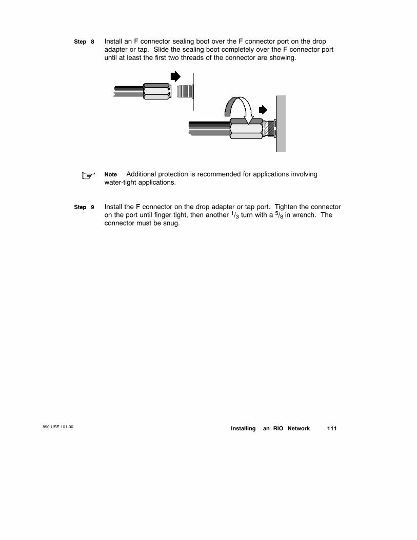
Installing an RIO Network890 USE 101 00 111
Step 8 Install an F connector sealing boot over the F connector port on the dropadapter or tap. Slide the sealing boot completely over the F connector portuntil at least the first two threads of the connector are showing.
Note Additional protection is recommended for applications involvingwater-tight applications.
Step 9 Install the F connector on the drop adapter or tap port. Tighten the connectoron the port until finger tight, then another 1/3 turn with a 5/8 in wrench. Theconnector must be snug.
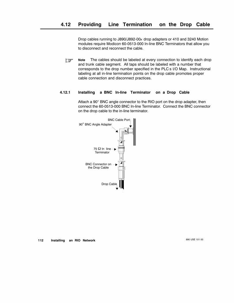
890 USE 101 00112 Installing an RIO Network
4.12 Providing Line Termination on the Drop Cable
Drop cables running to J890/J892-00x drop adapters or 410 and 3240 Motionmodules require Modicon 60-0513-000 In-line BNC Terminators that allow youto disconnect and reconnect the cable.
Note The cables should be labeled at every connection to identify each dropand trunk cable segment. All taps should be labeled with a number thatcorresponds to the drop number specified in the PLC’s I/O Map. Instructionallabeling at all in-line termination points on the drop cable promotes propercable connection and disconnect practices.
4.12.1 Installing a BNC In-line Terminator on a Drop Cable
Attach a 90° BNC angle connector to the RIO port on the drop adapter, thenconnect the 60-0513-000 BNC In-line Terminator. Connect the BNC connectoron the drop cable to the in-line terminator.
Drop Cable
BNC Cable Port90° BNC Angle Adapter
75 Ω InlineTerminator
BNC Connector onthe Drop Cable

Installing an RIO Network890 USE 101 00 113
4.12.2 Optional Drop Cable In-line Termination
All drop adapters—except those listed in Section1.4.4—provide 75 Ωtermination inside the modules themselves. You may want to considerproviding the drop cables leading to these adapters with self-terminating F orBNC adapters to assure proper cable termination when the drop adapter isdisconnected.
Modicon 52-0370-000 Self-terminating BNC Adapters, which are standard in984 Hot Standby systems, may be used optionally in cases whereself-terminating BNC connections are desired. Modicon 52-0411-000Self-terminating F Adapters may be used for quad shield drop cable, andModicon 52-0399-000 Self-terminating F Adapters may be used for non-quadshield drop cable.
Installing A Selfterminating Adapter on a Drop CableStep 1 Cut the drop cable into two sections, one of which is 18 in (45 cm) long.
Install an F or BNC connector on each end of the 18 in cable section.
Step 2 Install an F connector on one end of the longer drop cable section and theselfterminating F or BNC adapter on the other end.
Step 3 Connect the 18 in section of drop cable to the cable port on the RIO dropadapter using the end that has the label attached closer to it (connection pointA). Connect the other end of the 18 in section of drop cable to theself-terminating adapter on one end of the longer drop cable (connection pointB).
18 in (45 cm) 50 ... 140 ft (15 ... 40 m)
Connects toDrop Adapter
Connects toTap Port
SelfterminatingAdapter
LabelLonger Section of
Drop Cable
A B
Step 4 Connect the F connector on the other end of the longer drop cable section tothe tap port. The drop connection is now complete.
Step 5 To disconnect the drop from the network while the network is running,disconnect the 18 in drop cable section from the selfterminating adapter(connection point B), then from the drop adapter (connection point A).
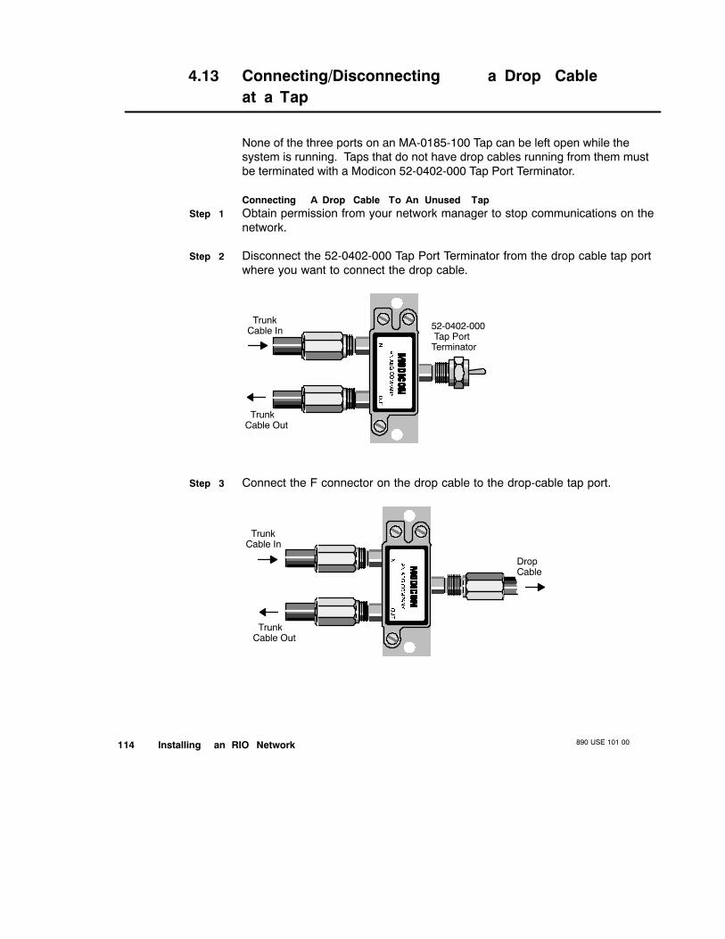
890 USE 101 00114 Installing an RIO Network
4.13 Connecting/Disconnecting a Drop Cableat a Tap
None of the three ports on an MA-0185-100 Tap can be left open while thesystem is running. Taps that do not have drop cables running from them mustbe terminated with a Modicon 52-0402-000 Tap Port Terminator.
Connecting A Drop Cable To An Unused TapStep 1 Obtain permission from your network manager to stop communications on the
network.
Step 2 Disconnect the 52-0402-000 Tap Port Terminator from the drop cable tap portwhere you want to connect the drop cable.
TrunkCable In
TrunkCable Out
52-0402-000Tap Port
Terminator
Step 3 Connect the F connector on the drop cable to the drop-cable tap port.
TrunkCable In
DropCable
TrunkCable Out

Installing an RIO Network890 USE 101 00 115
Disconnecting A Drop Cable From A TapStep 1 Obtain permission from your network manager to stop communications on the
network.
Step 2 Disconnect the F connector on the drop cable from the drop-cable tap port.
Step 3 Insert a Modicon 52-0402-000 Tap Port Terminator terminator in the drop-cabletap port.
Caution Do not connect a drop cable to or disconnect a drop cablefrom a tap on an ACTIVE network. Either of these two actions can causeexcessive communications errors on the network.
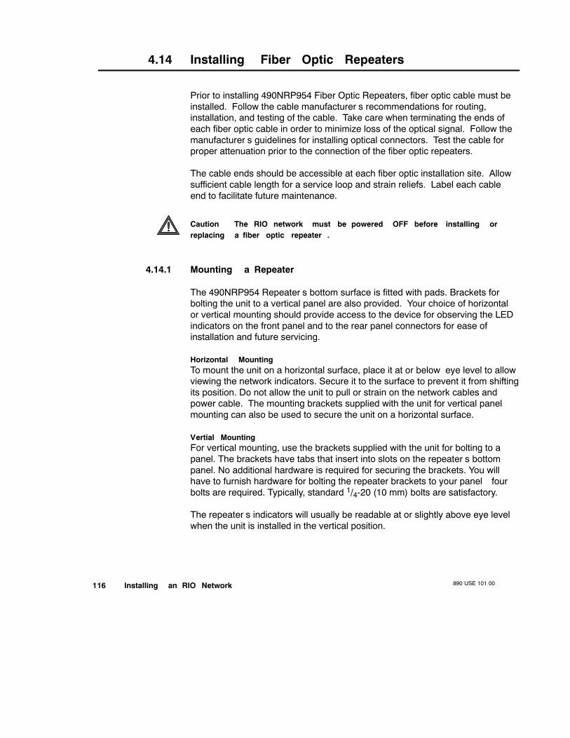
890 USE 101 00116 Installing an RIO Network
4.14 Installing Fiber Optic Repeaters
Prior to installing 490NRP954 Fiber Optic Repeaters, fiber optic cable must beinstalled. Follow the cable manufacturer’s recommendations for routing,installation, and testing of the cable. Take care when terminating the ends ofeach fiber optic cable in order to minimize loss of the optical signal. Follow themanufacturer’s guidelines for installing optical connectors. Test the cable forproper attenuation prior to the connection of the fiber optic repeaters.
The cable ends should be accessible at each fiber optic installation site. Allowsufficient cable length for a service loop and strain reliefs. Label each cableend to facilitate future maintenance.
Caution The RIO network must be powered OFF before installing orreplacing a fiber optic repeater .
4.14.1 Mounting a Repeater
The 490NRP954 Repeater’s bottom surface is fitted with pads. Brackets forbolting the unit to a vertical panel are also provided. Your choice of horizontalor vertical mounting should provide access to the device for observing the LEDindicators on the front panel and to the rear panel connectors for ease ofinstallation and future servicing.
Horizontal MountingTo mount the unit on a horizontal surface, place it at or below eye level to allowviewing the network indicators. Secure it to the surface to prevent it from shiftingits position. Do not allow the unit to pull or strain on the network cables andpower cable. The mounting brackets supplied with the unit for vertical panelmounting can also be used to secure the unit on a horizontal surface.
Vertial MountingFor vertical mounting, use the brackets supplied with the unit for bolting to apanel. The brackets have tabs that insert into slots on the repeater’s bottompanel. No additional hardware is required for securing the brackets. You willhave to furnish hardware for bolting the repeater brackets to your panel—fourbolts are required. Typically, standard 1/4-20 (10 mm) bolts are satisfactory.
The repeater’s indicators will usually be readable at or slightly above eye levelwhen the unit is installed in the vertical position.
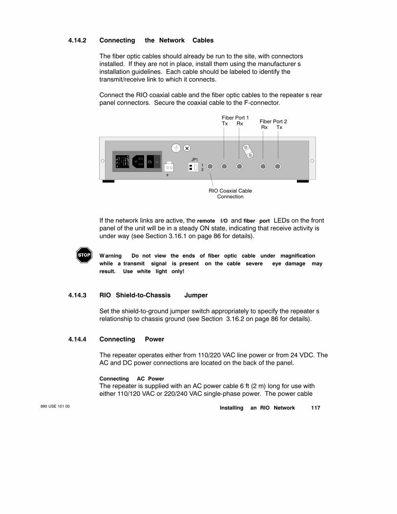
Installing an RIO Network890 USE 101 00 117
4.14.2 Connecting the Network Cables
The fiber optic cables should already be run to the site, with connectorsinstalled. If they are not in place, install them using the manufacturer’sinstallation guidelines. Each cable should be labeled to identify thetransmit/receive link to which it connects.
Connect the RIO coaxial cable and the fiber optic cables to the repeater’s rearpanel connectors. Secure the coaxial cable to the F-connector.
Fiber Port 2Rx Tx
Fiber Port 1Tx Rx
RIO Coaxial CableConnection
JP112
+
If the network links are active, the remote I/O and fiber port LEDs on the frontpanel of the unit will be in a steady ON state, indicating that receive activity isunder way (see Section 3.16.1 on page 86 for details).
W arning Do not view the ends of fiber optic cable under magnificationwhile a transmit signal is present on the cable—severe eye damage mayresult. Use white light only!
4.14.3 RIO Shield-to-Chassis Jumper
Set the shield-to-ground jumper switch appropriately to specify the repeater’srelationship to chassis ground (see Section 3.16.2 on page 86 for details).
4.14.4 Connecting Power
The repeater operates either from 110/220 VAC line power or from 24 VDC. TheAC and DC power connections are located on the back of the panel.
Connecting AC PowerThe repeater is supplied with an AC power cable 6 ft (2 m) long for use witheither 110/120 VAC or 220/240 VAC single-phase power. The power cable
890 USE 101 00118 Installing an RIO Network
connects to a socket on the rear panel. Grounding is supplied through thepower cable. The AC power cable is keyed for North American 110/120 VACpower outlets. If necessary, install a different plug on the cable for the powersource at your site.
Turn the power switch OFF and remove the AC power cable from the repeater.Set the power selector plug to the 110/120 VAC or 220/240 VAC position for thepower source at your site. To do this, remove the power selector plug by pryingunder its tab with a small screwdriver. Set the plug to the proper voltageposition as shown on the plug body, then reinsert it. Insert the power cable intothe rear panel connector. Secure the power cable under the strain relief. Plugthe cable into the AC power source.
Connecting DC PowerYour DC power source must supply 1 A at 24 V. Switch the DC source OFF.Connect the source to DC power terminals, observing the proper polarity.Secure the power wiring under the strain relief.
Power CableConnector
PowerSwitchPower Selector
Plug and Fuse
JP112
24 VDCConnection
+
Caution Fiber optic repeaters cannot be operated with both 115 VACand 24 VDC power applied at the same time.
GroundingThe repeater obtains its ground in the AC power cord via the green gnd wire orthrough the DC wire. Using a continuity tester, verify the repeater chassis isgrounded to the site ground. To ensure proper grounding, connect the chassisground to the site ground by direct chassistoground connection.
Applying AC PowerIf you are using AC line power, reapply AC to the fiber optic drop site. The mainpower switch controls the power to the unit. Set the power switch to the | (ON)position. The unit’s power OK LED will illuminate.
Installing an RIO Network890 USE 101 00 119
Applying DC PowerIf you are using DC power, switch on your DC to the repeater. The unit’s powerOK LED will illuminate.
Caution When DC power is used, the POWER switch on the unit isdisabled. Power is supplied to the unit when source power is activated.Under DC power , the unit does not provide surge protection.

890 USE 101 00120 Installing an RIO Network
4.15 Terminating the Trunk Cable
The trunk cable must be terminated by inserting a Modicon 52-0422-000 TrunkTerminator in the trunk-out port of the last tap on the RIO network:
Trunk Cable
Drop Cable
52-0422-000Trunk Terminator
Trunk-InPort
Trunk-OutPort
Last Tap on the RIO Network

Installing an RIO Network890 USE 101 00 121
4.16 Installing the Ground Point
The cable system should be grounded at a point within 20 ft of the RIOprocessor at the head-end of the network. A ground block, a single ModiconMA-0185-100 Tap, a Modicon MA-0186-100 Splitter, or an optional Modicon60-0545-000 Ground Block may be used, assuring that the cable system will bepermanently grounded even when disconnected from the RIO processor.
Note Do not disconnect the cable system from the central groundpoint—disconnecting the system from ground will create an unfavorablefloating ground condition.
A screw is provided on taps, splitters, and ground blocks as the grounding point.If you use a ground block, mount it in a small enclosure.
To install a 60-0545-000 Ground Block:
V Cut the cable
V Install two F connectors on the cable
V Attach two F connectors to the ground block
V Wire the ground block to an appropriate ground (typically building steel)

Testing and Maintaining an RIO Network890 USE 101 00 123
Chapter 5Testing and Maintaining anRIO Network
V Maintenance and Testing Requirements
V RIO System Tests
V Problem Sources on an RIO Network
V On-line and Off-line Error Isolation
V Troubleshooting Fiber Optic Repeaters

890 USE 101 00124 Testing and Maintaining an RIO Network
5.1 Maintenance and Testing Requirements
A properly installed RIO system will achieve reliable communications betweenthe nodes with the certainty that timing and integrity are consistent andrepeatable. After the installation has been completed, the RIO network must betested to ensure proper operation of all network components. Each test shouldbe documented to provide data for ongoing maintenance.
5.1.1 Documenting Drop Maintenance Information
A maintenance information log form (shown on the next page) should be usedfor documenting key information about the type of RIO adapter used at eachdrop; the adapter type—e.g., a J890, P892—serial number, revision level(PROM combo), and physical location of the drop can be recorded. If theadapter does not have a PROM combo, the PROM combo field may be used tolog the revision of the software or hardware of the particular node.
Before an RIO drop is powered up, a PROM combo label with the four-digitnumber on it should be written beside it’s location on the topology plan. Thiswill allow quick reference of the option board’s firmware revision should itbecome necessary to replace the PROMs (due to failure or upgrade).

Testing and Maintaining an RIO Network890 USE 101 00 125
RIO Drop Maintenance Information Log
Customer Network
Location Plant
Revision/Approved by DateDrop Number Node Type Serial Number PROM Combo Plant Location

890 USE 101 00126 Testing and Maintaining an RIO Network
5.2 RIO System Tests
A battery of up to eleven tests can be performed to ensure reliability of the RIOsystem. These tests are generally performed in the order described below.
5.2.1 Fundamental RIO System Tests
Tests 1 ... 7 are the minimum recommended tests for Modicon RIO networks.They can be performed by most customers in the field given the proper testequipment.
Test 1 Pre-installation Cable TestPerformed while the cable is still on the reel, this test includes includes:
V Attenuation sweep test
V Return loss sweep test
V Attenuation measurements test
V TDR test
Modicon and Comm/Scope cables are pretested and do not need to be retestedunless shipping damage is suspected or unless you prefer to test all cableon-site before installation.
Test 2 Visual InspectionA check of the entire network including but is not limited to:
V Tap installation
V Cable installation
V Cable routing
V Grounding
V Connector installation
Test 3 Induced Voltage TestA check for any potentially hazardous AC voltages on the cable system.
Testing and Maintaining an RIO Network890 USE 101 00 127
Test 4 Grounding TestA check for potential problems with the cable shields and verify systemgrounding to a low impedance earth ground.
Test 5 Oscilloscope Noise AnalysisDetermines the noise level—i.e., whether power spikes are present. Typicallythe noise level should not exceed 20 mV.
Test 6 Time Domain Reflectometer (TDR ) TestPerformed on all drop cables and at all trunk end points. It tests the integrity ofall drop cables up to and including the tap port, as well as the trunk cablecomponents. Results are produced on a strip chart record with the location ofimpedance mismatches and the extent of the impedance mismatch. Thespecification limit for any TDR measurement is determined by the cause of themismatch.
Test 7 Attenuation Sweep TestTests the ability of the cable system to pass RIO signals without degradationover the full bandwidth. The test is conducted from the RIO processor node toall trunk and drop end points.
5.2.2 RIO System Tests for Critical Applications
Tests 8 ... 10 guarantee performance—if your RIO network is critical to theoperation of your process, these tests are highly recommended. They can alsobe beneficial if your operating environment is extremely noisy.
Test 8 Attenuation MeasurementsTaken during the attenuation sweep test or using the LMT/LMR attenuationmeasurement system. This test yields the maximum attenuation on the trunkand on the entire network, end to end. The attenuation should be close to thedesigned attenuation and must never exceed 35 dB (32 dB for the host-basedPLCs).
Test 9 Return Loss Sweep TestA test of reflections on the network. It tests the trunk cable at all end points andat least one drop cable for return loss over the full RIO bandwidth. The returnloss on the trunk must be below 16 dB, and below 14 dB on any drop.
Test 10 Noise Floor Level TestDetermines the level of noise on the network within the full bandwidth used byRIO. Ensures that the noise floor level is below +10 dBmV over the full RIObandwidth at any trunk end point and at least one drop cable.
890 USE 101 00128 Testing and Maintaining an RIO Network
5.2.3 Network Startup
The last test should be performed on all startups.
Test 11 Network StartupTests all the nodes on the network while they are communicating.Communication error counters are monitored over a given time period.
Testing and Maintaining an RIO Network890 USE 101 00 129
5.3 Problem Sources on an RIO Network
Noise on the RIO network is a frequently identified problem source in thetroubleshooting process. The symptom is usually excessive retries at the RIOdrop adapters. Most noise problems are caused either by inadequate spacingof RIO cable or components from power cables or by an inadequate earthground. The other common problem source is poor installation.
5.3.1 Solving Spacing Problems
Spacing problems can frequently be identified in a visual check on the network.Make sure that a spacing of 12 ... 14 in per kV of power is maintained betweenthe cables and components in your RIO system and any type of low to mediumpower cable.
We recommend that you avoid all power cable including DC power cables. DCpower cables pick up spikes from AC power cables and then induce the spikesonto the RIO cable. Even the low power AC cables can induce spikes onto theRIO cable system.
5.3.2 Potential Grounding Problems
A low impedance earth ground is typically hard to measure properly; even afterthe measurement is performed, it can be misleading. A properly installedModicon RIO system is grounded at or near (within 20 ft) the RIO processor atthe head-end of the network. The only other condition under which you shouldground the network is when the cable enters or exits a building (per NEC code).
If the system is not properly grounded, it will produce excessive retries. Werecommend that you connect a separate ground wire from the programmablecontroller directly to plant ground. The wire should minimally be 14 gaugegreen or bare wire. If the controller is grounded only to the panel, make surethe panel wire is sufficient (typically 2 gauge) to handle the load of the paneland that a separate wire is used to ground the panel. Do not use conduit toground a controller or panel.
Another prevalent grounding problem is with the equipment connected to thecontroller. When large motors, drives, or spindles are not properly grounded,they cause an excessive amount of EMI/RFI and conduct this noise onto thepower system. EMI/RFI interferences are sometimes misinterpreted asprogrammable controller problems. You should consult with the manufacturer ofthese products to ensure that they are properly grounded.

890 USE 101 00130 Testing and Maintaining an RIO Network
5.3.3 Problems Stemming from Poor Installation
Defective media products can account for some system problems. The maininstallation problem is usually in the connectors. Using recommendedconnectors and tools will minimize these kinds of problems.
Installation problems can usually be tracked by performing a visual inspection ofthe network. You should be able to pull on the F or BNC connections withoutthem falling off. Connectors may also need to be tightened onto the deviceports.
Defective media products like cable and taps cannot be seen, and need to betested using the procedures described in Section 5.2.
Testing and Maintaining an RIO Network890 USE 101 00 131
5.4 On-line and Off-line Error Isolation
RIO troubleshooting is a process of isolating problems in an on-line system,usually with the aid of LED indicator lamps and system statistics.
Media-related problems are generally solved off-line, not by using LEDs orsystem statistics. However, once a problem has been isolated to it’s sourceusing any of the off-line tests described in the last chapter, it is sometimespossible to locate the problem source using the on-line troubleshootingprocedures discussed below.
For instance, if a network has passed its sweep and TDR tests but has failed itsnoise floor test, the network can sometimes be brought up to troubleshoot thesource of the noise. By using the retry counters, the noise source can beisolated and the problem corrected. Ineffective grounding of externalnon-Modicon equipment, ineffective grounding of Modicon equipment, orinadequate spacing of coaxial from power cable can be isolated while thenetwork is on-line.

890 USE 101 00132 Testing and Maintaining an RIO Network
5.5 Troubleshooting Fiber Optic Repeaters
Here is a typical point-to-point RIO fiber optic link:
Coaxial Cable
PLC RIO I/O I/O I/OP/S
Head (with RIO Drop #1)
Coaxial Cable
FR1 (Drop)
FR2 (Head)
RIO Drop #2RIOP/S I/O I/O I/O
Tx
Tx
Rx
Rx
There are well documented procedures for analyzing the wiresidecharacteristics of this type application, and it is recommended they be used as afirst line of attack and afterward whenever trouble is suspected.
If the coaxial system is working properly, it will cause the remote I/O LED onFR1 to illumunate. If that LED illuminates as expected, then the fiber port 1LED on FR2 should illuminate and the fiber port 2 LEDs on FR1 and FR2should be OFF.
If the fiber port 1 LED on FR2 does not illuminate, check the Tx and Rxconnections on the fiber link. If the problem persists, substitute a known goodrepeater for FR2 and repeat the procedure. If the problem still persists, checkthe drop adapter and coaxial link at drop #2. If all this still checks out properly,then you have isolated the problem to faulty fiber cable, and manufacturer’s testprocedures must be used.
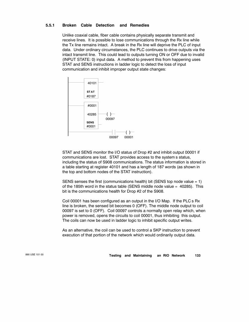
Testing and Maintaining an RIO Network890 USE 101 00 133
5.5.1 Broken Cable Detection and Remedies
Unlike coaxial cable, fiber cable contains physically separate transmit andreceive lines. It is possible to lose communications through the Rx line whilethe Tx line remains intact. A break in the Rx line will deprive the PLC of inputdata. Under ordinary circumstances, the PLC continues to drive outputs via theintact transmit line. This could lead to outputs turning ON or OFF due to invalid(INPUT STATE: 0) input data. A method to prevent this from happening usesSTAT and SENS instructions in ladder logic to detect the loss of inputcommunication and inhibit improper output state changes:
#0001
40285
#0001
40101
ST AT
#0187
00097
SENS
( )00001
( )00097
STAT and SENS monitor the I/O status of Drop #2 and inhibit output 00001 ifcommunications are lost. STAT provides access to the system’s status,including the status of S908 communications. The status information is stored ina table starting at register 40101 and has a length of 187 words (as shown inthe top and bottom nodes of the STAT instruction).
SENS senses the first (communications health) bit (SENS top node value = 1)of the 185th word in the status table (SENS middle node value = 40285). Thisbit is the communications health for Drop #2 of the S908.
Coil 00001 has been configured as an output in the I/O Map. If the PLC’s Rxline is broken, the sensed bit becomes 0 (OFF). The middle node output to coil00097 is set to 0 (OFF). Coil 00097 controls a normally open relay which, whenpower is removed, opens the circuits to coil 00001, thus inhibiting this output.The coils can now be used in ladder logic to inhibit specific output writes.
As an alternative, the coil can be used to control a SKP instruction to preventexecution of that portion of the network which would ordinarily output data.

RIO Cable Material Suppliers890 USE 101 00
135
Appendix ARIO Cable Material Suppliers
V Comm/Scope, Inc.
Network Cable Division
P.O. Box 1729
1375 Lenoir-Rhyne Blvd.
Hickory , NC 28602
Telephone:(800) 982-1708(704) 324-2200
Telex: 802-166Fax: (704) 328-3400
V Belden Corporation
P.O. Box 1980
Richmond, IN 47374
Telephone:(317) 983-5200Telex: 499-7255 (domestic)
94-5989 (international)Fax: (317) 983-5294
V Times Fiber Communications, Inc.
358 Hall Avenue
P.O. Box 384
W allingford, CT 06492 0384
Telephone:(203) 265-8500Fax: (203) 265-8422

890 USE 101 00136 RIO Cable Material Suppliers
V Gilbert Engineering
P.O. Box 23189 5310 W est Camelback
Phoenix, Arizona 850633189
Glendale, Arizona 853017597
Telephone:(602) 245-1050(800) 528-5567
Fax: (602) 934-5160TWX: 910-951-1380
V LRC Electronics
901 South Avenue
P.O. Box 111
Horseheads, NY 14845
Telephone:(607) 739-3844Telex: 5101-011-251Fax: (607) 739-0106
V Raychem Corporation
300 Constitution Drive
Menlo Park, CA, 94025
Telephone:(415) 361-2288TWX: 910-373-1728

Glossary890 USE 101 00 137
Appendix BGlossary
amplitude A measure of the strength of a signal.
application A user program.
armor A metal wrapping around a coaxial cable used for mechanicalprotection.
attenuation Signal loss through an electrical circuit or conductor.(see also signal loss )
bandwidth A range of frequencies.
baseband A type of network having a single communications channel. RIO isa baseband communications network.
bend radius The radius of the arc along which a cable may be bent
bit error rate The number of bits received in an error divided by the totalnumber of bits received.
braid A wire mesh used to construct the shield of a coaxial cable.
bus A single cable connecting multiple points.
890 USE 101 00138 Glossary
cable shield The outer conductor of a coaxial cable used to protect the signalon the cable from noise.
cable sweep A test that assures proper network response within a givenfrequency range.
carrier detect A status LED indicating the presence of activity on the network.
CA TV Community antenna television.
center conductor The center wire in a coaxial cable, usually made of copperor copperclad metal.
characteristic impedance The ratio of signal voltage to signal current on atransmission line.
coaxial cable A type of transmission line having a center conductorsurrounded by an insulator (a dielectric), then an outer shield.
communications The transmitting and receiving of messages between nodes(intelligent devices) on the network.
COMM ACTIVE A status LED indicating that the modem is communicating.
COMM ERROR A status LED indicating that the modem has detected an errorin the message.
COMM READY A status LED indicating that the modem is able tocommunicate.
core The center region of a coaxial or fiber optic cable through which the signalis transmitted.
data field The data portion of a message frame, containing the rudimentarycommand or data.
destination address The part of the RIO message that defines the address ofthe destination node.
dispersion The cause of bandwidth limitations in a fiber optic signal.Dispersion causes a broadening of input pulses along the length of the fiber.Three major types are: mode dispersion caused by differential optical pathlengths in a multimode fiber; material dispersion caused by a differential delayof various wavelengths of light in a waveguide material; and waveguidedispersion caused by light traveling in both the core and cladding materials insingle-mode fibers.

Glossary890 USE 101 00 139
drop An address on the RIO network. (see also node )
drop cable The cable that runs between a tap in the trunk cable and theconnector to the RIO drop adapter at the drop.
drop loss The amount of attenuation (signal loss) in the drop cable and theconnector—i.e., between the tap and the node.
dual cable An RIO network topology in which two cable systems are run fromthe head processor in a PLC to two different groups of drop adapter nodes. Adual cable topology requires dual RIO comm ports in the RIO processor nodeand a single RIO comm port in each drop adapter. (see also redundant cable )
fiber A thin filament of glass. an optical waveguide consisting of a core and acladding is capable of carrying information in the form of light.
fiber optics Light transmission through optical fibers for communications orsignaling.
earth ground A connection to earth, usually through structural steel or waterpipes.
egress Signal radiated by the transmission line.
EMI Electromagnetic interference, usually caused by inductive devices such asmotors. EMI causes noise that can be radiated in the air or conducted throughpower lines.
F connector An industry standard connector for coaxial cable.
foil A mylarbacked aluminum foil used for shield construction on coaxialcable.
frame A message unit, particularly that part between the start delimiter and theend delimiter.
frame check sequence A calculated number sent with a message unit andchecked by the receiver to assure message integrity.
graded-index Fiber design in which the refractive index of the core is lowertoward the outside of the fiber core and increases toward the center of the core.It bends the rays inward and allows them to travel faster in the lower index-of-refraction region. This type of fiber provides high bandwidth capabilities.
ground A common signal return point from various circuit elements.
890 USE 101 00140 Glossary
ground block An RIO network component that may be used as thesinglepoint ground for the system.
HDLC (high level data link control) The link layer protocol used on an RIOcommunications network.
Hot Standby System A 984 capability in which two identically configured PLCsare connected to the same process via RIO cable systems. One primary PLCcontrols the process while the other standby constantly monitors the process. Ifthe primary controller fails, the backup controller takes over system controloperations.
impedance (see characteristic impedance )
ingress The noise picked up by a transmission line from outside sources.
input module A device used to connect field inputs. This module mounts intoan I/O housing at a drop/channel location.
insertion loss The amount of signal lost through a device.
LAN (local area network) A computer network for communication amongnodes over a relatively small area (usually less than 10 mi)
link layer The RIO communications layer that assures proper messagetransmission and reception over the network.
mandrel The inner section edge of the Fconnector. As you look into theFconnector, the mandrel is the flat edge; the white dielectric must be aligned tothe edge of the mandrel.
mechanical splicing Joining of two fiber optic cables together by mechanicalmeans—e.g., elastrometric splicing—to enable a continuous signal.
media Cable system components used to make a network.
Modbus A proprietary Modicon protocol for communicating between Modiconsystems and host devices—e.g., computers, data access panels
modem (modulatordemodulator) A device that encodes digital data from ahost device to an RF signal transmitted over the network and vice versa.
multimode fiber An optical waveguide in which light travels in multiple modes.Typical core/cladding sizes are 50/125 µm, 62.5/125 µm, and 100/140 µm.
network A system consisting of the cable media components and thecommunication nodes.

Glossary890 USE 101 00 141
node An intelligent unit or option on the RIO network, either an RIO processoror a drop adapter.
noise EMI/RFI generated outside the media by electrical devices and inducedon the cable system.
nondirectional signal A signal that is allowed to travel in any possibledirections or is not restricted to travel in only one direction.
output module A device used to connect to field outputs. This module mountsinto an I/O housing at a drop/channel location.
packet A selfcontained block of data with specific protocol parameters, whichis transmitted over the media. A message can comprise many packets.
phase delay distortion The difference in arrival time between the higherfrequency signals and lower frequency signals over distance. Wave formdistortion results from the delay in the arrival of the lower frequency signals.Phase delay increases as the length of the cable medium increases.
preamble A preset bit pattern at the start of a transmission, allowing othernodes to synchronize with the incoming message.
protocol An agreedupon set of parameters known to each node that allowsthe nodes to communicate with each other.
pull strength The maximum allowable torque that may be used to pull a cablethrough a conduit or enclosure.
redundant cable An RIO network topology in which two cable systems are runfrom the RIO processor in a PLC to the same group of drop adapter nodes. Adual cable topology requires dual RIO comm ports in the RIO processor nodeand in all the adapters (see also dual cable ).
redundant programmable control (see Hot Standby System )
remote I/O drop adapter A node at each remote drop that connects to thecoaxial cable system, processes messages from the remote I/O processor, andupdates the I/O at the drop. (see also node )
remote I/O head processor The master node for the RIO network; itprocesses commands for the PLC, and it sends messages to/receivesmessages from the adapter nodes on the network.
repeater A device that consists of a transmitter and receiver or transceiver,used to amplify a signal to increase signal length.
890 USE 101 00142 Glossary
response window A finite waiting time from transmission to an expected reply,preventing the system from being locked out by a nonreplying node.
retransmission The resending of a message because transmission error inthe messagegenerating node or a failure to receive the message at a receptornode.
retry (see retransmission )
retry count The number of times the RIO processor has had to retransmit amessage.
return loss The amount of signal reflected back toward the signal origin,expressed in dB down from the original signal. Return loss is caused byimpedance mismatch; the high the return loss, the better. (see also VSWR )
RG-6 A standard coaxial cable type, providing good shielding and fair signalloss.
RG-1 1 A standard coaxial cable type, providing good shielding and medium tolow signal loss.
RFI (radio frequency interference) Noise caused by another transmittingdevice.
scattering A property of glass that causes light to deflect from the fiber andcontribute to attenuation on the fiber link.
selfterminating Fadapter A device used on a drop cable to provide propertermination in the event that the node is disconnected from the drop cable.
semirigid cable A standard coaxial cable with very low loss and maximumshielding over the maximum trunk cable distance.
sequence number Part of the RIO message sent over the medium so that thenodes can track packet numbers in the event that a packet retransmissionbecomes necessary.
shield The outer conductor of a coaxial cable that protects the messagetransmission on the cable from noise.
shield effectiveness Measured in dB—the higher the value, the better thecable shield.
signal loss The amount of signal lost through media devices. (see alsoattenuation )
Glossary890 USE 101 00 143
spectrum analyzer A device used to test the medium’s ability to transmit withina frequency range. It shows signal amplitude on the yaxis and frequencymeasurement on the xaxis.
star coupler Optical component that allows emulation of a bus topology in fiberoptic systems.
start frame delimiter A preset octet pattern marking the start of the messagepacket.
sweep generator A test device for checking the amplitude integrity of amedium over the bandwidth of RIO signals. It generates a userspecifiedoutput signal at a userspecified frequency.
tap A passive device used to isolate a node from the trunk cable. It allows onlya portion of the signal to be transmitted through a port on the tap.
tap insertion loss The amount of signal loss in the trunk caused by inserting atap.
tap terminator A standard terminator for open ports on a tap.
TDR (time domain reflectometer) A test device for measuring the integrity ofa medium regarding impedance mismatch and connections.
terminator A piece of hardware containing a 75 Ω resistor, used at the ends ofthe trunk cable, at each node, and at each tap outlet to match the characteristicimpedance of the cable. (see also characteristic impedance )
through loss The signal loss through a device caused by physical insertion ofthe device in the trunk cable. (see also insertion loss )
topology The complete media specification. The topology should be mappedinto a log with all installation details for future reference.
I/O map A table in the PLC’s user memory that directs I/O data to the properdrop/channel and I/O module.
transfer impedance A measure of cable’s ability to reject noise. The lower thenumber, the better the cable.
trunk cable The main cable running from the RIO processor upon which tapsare installed, permitting the drop adapters to connect to the cable system.
trunk terminator a precision terminator used at the two ends of the trunkcable. (see also terminator )
890 USE 101 00144 Glossary
velocity of propagation The speed of the signal in the cable, expressed as apercentage of the speed of light in free space.
VSWR (voltage standing wave ratio) The measure of the signal reflectedback from a transmitted signal. Lower ratios indicate better impedance matchand cause less signal to be reflected back at the transmitting source. (see alsoreturn loss )
wavelength The distance between the same point on adjacent waves.
zero crossing The condition when the wave form crosses 0 V, either on avoltage rising or on a voltage falling. (see also phase continuous signaling )


![HAAS+SOHN Rukov€¦ · Zatriedenie peletov 'ch kachiel' podt'a EN 14785 Základní technické úda.e eletov 'ch kachie" Dosiehnut ' tepeln v 'kon (100%) [kW] Menovit. v 'kon kW Obsah](https://img.pdfslide.net/doc/110x75/60507bd2f5300900737070d0/haassohn-rukov-zatriedenie-peletov-ch-kachiel-podta-en-14785-zkladn-technick.jpg)