Embed Size (px)
Citation preview

Vapor Recovery Test Procedure
TP - 201.1
DETERMINATION OF EFFICIENCY OF PHASE I VAPOR RECOVERY SYSTEMS OF
DISPENSING FACILITIES WITHOUT ASSIST PROCESSORS
Adopted: April 12, 1996

This method is being amended. For ease of viewing, the method is shown as repealed text and proposed text.

California Environmental Protection Agency Air Resources Board
Vapor Recovery Test Procedure
TP-201.1
Determination of Efficiency of Phase I Vapor Recovery Systems of
Dispensing Facilities without Assist Processors
1 APPLICABILITY
A set of definitions common to all certification and test procedures is in:
D-200 Definitions for Certification Procedures and Test Procedures for Vapor Recovery Systems
For the purpose of this procedure, the term "ARB" refers to the State of California Air Resources Board, and the term "ARB Executive Officer" refers to the Executive Officer of the ARB or his or her authorized representative or designate.
1.1 General Applicability
This procedure is used to quantify the Phase I volumetric efficiencies during bulk gasoline deliveries at gasoline distribution facilities (GDF). It is applicable for the determination of compliance at those facilities which are not equipped with an assist processor (e.g. Hirt or Hasstech Phase II systems are equipped with an assist processor). Assist systems actively pump vapors to processors which control emissions by burning, adsorbing, or condensing hydrocarbon vapors. The active pump in the system and the emissions point at the processor outlet in addition to the vent require additional steps in the test procedure.
1.2 Modifications
Modification of this procedure may be necessary for vapors and fluids other than the hydrocarbon vapors associated with the dispensing of gasoline.
Any modification of this method shall be subject to approval by the ARB Executive Officer.
2 PRINCIPLE AND SUMMARY OF TEST PROCEDURE

NOTE: ENTIRE TEXT OF THIS PAGE IS PROPOSED FOR REPEAL.
During a bulk gasoline delivery, the volume of gasoline delivered from the cargo tank to the GDF storage tank is recorded. The volume of gasoline vapor discharged from the vent pipe(s) of the storage tank(s) is measured. From these parameters the Phase I volumetric efficiency is determined.
If a Phase I system fails to meet 95% volumetric efficiency, the gasoline cargo tank shall be tested, pursuant to TP-204.2, to determine compliance with the daily performance standards for gasoline cargo tanks. For this application, TP-204.1 and TP-204.3 are inappropriate.
3 BIASES AND INTERFERENCES
3.1 Bulk Delivery Vapor Leaks
Any vapor leak exceeding 21,000 ppm (as propane), during the gasoline bulk delivery, precludes the use of this method.
3.2 Cargo Tank Performance
Gasoline cargo tanks exceeding the static pressure performance standards (see CP-204) preclude the use of this method.
4 SENSITIVITY, RANGE, AND PRECISION
The minimum readability of the pressure gauges shall be 0.1 inches of water column.
The minimum accuracy of the pressure gauges shall be 2 % of full scale.
5 EQUIPMENT
5.1 Positive Displacement Meter(s)
Use rotary type positive displacement meter(s) with a back pressure limit (BPL) less than:
1.10 inches water column at a flowrate of 3,000 CFH down to 0.05 inches water column at a flowrate of 30.0 CFH.
Meter(s) shall be equipped with taps accommodating the following equipment:
(1) taps on the inlet side for
(a) a thermocouple with a range of 0 to 150 oF and
(b) a pressure gauge with a range providing absolute pressure readings within 10 to 90% of the range (more than one gauge shall be used, if necessary) and
(2) taps on the inlet and outlet sides for a differential pressure gauge with a range of 0 to < 2x BPL (i.e. full scale shall be less than twice the back pressure limit).
5.2 Tubing
TP - 201.1 Page 2

NOTE: ENTIRE TEXT OF THIS PAGE IS PROPOSED FOR REPEAL.
Use 2.5 inch ID "flexhaust" tubing, or equivalent, to connect the vent pipe outlet to the inlet of the rotary positive displacement meter. The length of the tubing shall be the minimum required for proper connection.
5.3 Cargo Tank Pressure Assembly
Use Civicon 633-F and 633-D couplers, or equivalent, as shown in Figure 1. The assembly shall be equipped with a thermometer and a pressure gauge, or manometer(oil or water), capable of measuring -10 to +10 inches water column pressure at the gasoline cargo tank vapor coupler.
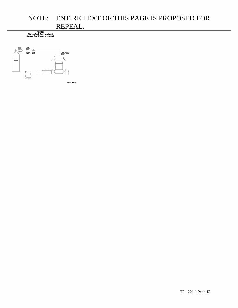
5.4 Storage Tank Pressure Assembly
For two-point Phase I systems, use a compatible OPW 634-B cap(s), or equivalent, equipped with a 0 to 0.5 inches water column pressure gauge and a center probe as shown in Figure 2. This equipment is only required if a test is conducted on a manifolded vapor recovery system.
5.5 Combustible Gas Detector
Use a Bacharach Instrument Company Model 0023-7356, or equivalent, to quantify any vapor leaks occurring during the gasoline bulk drop.
5.6 Barometer
Use a mercury, aneroid, or equivalent barometer accurate to within 5 millimeters of mercury ( 0.2 inches of mercury ).
5.7 Thermometers
Use three thermometers, or equivalent, with a range of 0 to 150 oF and accurate to within 2 oF.
5.8 Stopwatch
Use a stopwatch accurate to within 0.2 seconds to time the delivery rate of gasoline during the bulk drop.
6 CALIBRATION PROCEDURE
A record of all calibrations shall be maintained.
6.1 Analyzers
Follow the manufacturer's instructions concerning warm-up time and adjustments. On each test day prior to testing, zero the analyzer with a zero gas and span with a known concentration of calibration gas at a level near the highest concentration expected. Perform an intermediate zero and span calibration approximately 2 hours after the initial calibration and at any time a calibration drift is evident. Check for zero and span calibration drift at the end of the test period. All calibrations and adjustments shall be documented.
6.2 Volume Meters
TP - 201.1 Page 3

NOTE: ENTIRE TEXT OF THIS PAGE IS PROPOSED FOR REPEAL.
Meters shall be calibrated on an annual basis.
6.3 Pressure Transducers
Calibrate pressure transducers prior to testing and immediately following the test period with a static pressure calibrator for a range of -3 to +3 inches water or appropriate range of operation.
6.4 Temperature Transducers
Calibrate temperature transducers every six months using ambient air, the temperature of which is determined by a NIST traceable mercury-glass thermometer.
7 PRE-TEST PROTOCOL
7.1 Location of Test Site
Prototype systems will be located within 100 miles of Sacramento for testing. Other locations may be accepted at the discretion of the ARB Executive Officer.
7.2 Specification of Test, Challenge, and Failure Modes
The specification of test, challenge, and failure modes such as the number of liquid transfer episodes, volume and volumetric rate of liquid transfer, storage tank volumes, etc. shall be done according to the principles of CP-201 § 5 for the testing and evaluation of vapor recovery equipment.
7.3 System and Facility Preparation
System equipment and components shall be completely operational and any storage tanks involved in the test shall be filled to the appropriate volume a minimum of 24 hours prior to the scheduled test.
In addition, the system and facility shall be prepared to operate according to any specified test, challenge, and failure modes.
7.4 Specific Pre-Test Protocol Items
(1) Visual Inspection
Perform a visual inspection of all storage tank couplers. Inspect all vapor connections at the gasoline dispensers if Phase II vapor recovery is present.
(2) Meter Connections
Connect the positive displacement meter to the appropriate storage tank vent pipe using the flexible tubing. If a non-manifolded delivery consists of simultaneous delivery of more than one product grade, connect one positive displacement meter to each storage tank vent pipe.
(3) Phase I Vapor Recovery Data Sheet
TP - 201.1 Page 4

NOTE: ENTIRE TEXT OF THIS PAGE IS PROPOSED FOR REPEAL.
(a) Record the gas grade, capacity, and ullage for each storage tank on the Phase I Vapor Recovery Data Sheet shown in Figure 3.
(b) Record, on the Phase I Vapor Recovery Data Sheet, the initial meter readings from the positive displacement meter.
(c) Record, on the Phase I Vapor Recovery Data Sheet, the barometric pressure.
(4) Cargo Tank Vapor Assembly Connection
Connect the Cargo Tank Vapor Assembly to the vapor coupler on the gasoline cargo tank. If the cargo tank vapor coupler is equipped with a poppet, be sure to use a pressure assembly with a center probe.
(5) Storage Tank Pressure Assembly Connection
If a manifolded vapor recovery system with a two-point Phase I system is being tested, install a Storage Tank Pressure Assembly on the Phase I vapor connections of those tanks not receiving product. During each bulk drop record the maximum pressure in those tanks. For coaxial systems the pressure may be measured at the dispensers.
7.5 Ensure that no vehicle refueling will occur during the bulk gasoline delivery.
8 TEST PROCEDURE
The facility and system shall be prepared to operate according to any specified test, challenge, and failure modes.
8.1 General Data Collection
Record, on the Phase I Vapor Recovery Data Sheet, the gasoline grade(s) and quantities delivered
TP - 201.1 Page 5

during each bulk drop. Also record the cargo tank CT#, ARB decal number and expiration date, and the cargo tank compartment capacities.
8.2 Chronometric Data
Start the stopwatch when the bulk delivery begins and stop the stopwatch at the conclusion of the delivery. If possible, the delivery rate shall be determined for each cargo tank compartment.
8.3 Data Collection
Record the following parameters every 15 seconds during each gasoline bulk drop:
8.3.1 Phase I Vent Pipe Data Sheet
Meter readings, temperatures, and pressures at the positive displacement meter. Extreme care must be taken to record all positive displacements since occasional reverse flow conditions may occur. Record this data on the Phase I Vent Pipe Data Sheet shown in Figure 4.
8.3.2 Phase I Cargo Tank Data Sheet
Vacuum (or pressure) and temperature at the cargo tank pressure assembly attached to the cargo tank vapor coupler. Record this data on the Phase I Cargo Tank Data Sheet shown in Figure 5.
8.4 Continuous Monitoring
Continue to monitor the vent pipe emissions for a period of one hour after the bulk drop has been completed. During this one hour period the data collection required in § 8.3.1 shall be recorded at 5 minute intervals. These emissions are to be included in the Phase I efficiency calculation.
8.5 After the Bulk Drop
After the conclusion of the bulk drop:
(1)remove the Cargo Tank Pressure Assembly from cargo tank and the Storage Tank Pressure Assembly(s) from the storage tank(s);
(2)disconnect all instrumentation from the storage tank vent pipe(s) after concluding the one hour post-drop portion of the test;
(3)verify the quantities of gasoline delivered to each storage tank;
(4)record the final meter reading(s) at the storage tank vent pipe(s).
9 QUALITY ASSURANCE / QUALITY CONTROL (QA/QC)
This section is reserved for future specification.
10 RECORDING DATA

NOTE: ENTIRE TEXT OF THIS PAGE IS PROPOSED FOR REPEAL.
This section is reserved for future specification.
11 CALCULATING RESULTS
Note: In addition to other required calculations, vapor recovery system test results shall be calculated in units of pounds of hydrocarbon emitted per thousand gallons of fuel transferred for any results which are expressible in such units.
11.1 Volume of Vapors Discharged through "ith" Vent
This includes the storage tank vent(s) and any control system vent(s). FUNC{{V_{v i}~x~5 2 8~ LEFT [P_b~+~{{DELTA~h}OVER{1 3.6}} RIGHT ]} OVER {T_{v i}~x~2 9.9 2}}
=Vvsi
Where:
= total volume of vapors discharged through the "i-th" vent pipe, corrected Vvsi to 68oF and 29.92" Hg; SCF.
Pb = barometric pressure; inches Hg.
= total volume of vapors discharged through the "i-th" vent; ACF.Vvi
= average temperature in "i-th" vent line; oRTvi
h = average pressure at meter; inches H20 and
i = vent under consideration.
TP - 201.1 Page 7

11.2 Volume of Vapors Returned to the Cargo Tank:
FUNC {{0.1 3 3 7~x~G_t~x~5 2 8~ LEFT [P_b~+~{{DELTA{H}}OVER{1 3.6}} RIGHT ]}OVER{T_{t}~x~2 9.9 2}}
Vt =
Where:
Vt = volume of vapors returned to the cargo tank corrected to 68oF and 29.92" Hg; SCF.
Gt = volume of gasoline delivered; gallons.
H = final gauge pressure at cargo tank; in. H2O.
Tt = average temperature of vapors returned to cargo tank; oR.
Pb = barometric Pressure; inches Hg.
0.1337 = conversion factor; gallons to ft3.
11.3 Collection
Efficiency
FUNC{E~~~~=~~~~{V_t~-~V_{v s i}}OVER{V_t}~x~1 0 0}
Where:
E = Phase I volumetric efficiency; percent.
Vt = see 11.2.
= see 11.1.Vvsi
12 REPORTING RESULTS
Note: In addition to other required results, vapor recovery system test results shall be reported in units of pounds of hydrocarbon emitted per thousand gallons of fuel transferred for any results which are expressible in such units.
Results shall be reported as shown in Figure 6.

NOTE: ENTIRE TEXT OF THIS PAGE IS PROPOSED FOR REPEAL.
13 ALTERNATIVE TEST PROCEDURES
Test procedures, other than specified above, shall only be used if prior written approval is obtained from the ARB Executive Officer. In order to secure the ARB Executive Officer's approval of an alternative test procedure, the applicant is responsible for demonstrating to the ARB Executive Officer's satisfaction that the alternative test procedure is equivalent to this test procedure.
(1) Such approval shall be granted on a case-by-case basis only. Because of the evolving nature of technology and procedures for vapor recovery systems, such approval shall not be granted in subsequent cases without a new request for approval and a new demonstration of equivalency.
(2) Documentation of any such approvals, demonstrations, and approvals shall be maintained in the ARB Executive Officer's files and shall be made available upon request.
TP-201.1A Determination of Efficiency of
with Assist Processors
This procedure applies when the operation of an assist processor precludes testing by TP-201.1.
14 REFERENCES
This section is reserved for future specification.
15 EXAMPLE FIGURES AND FORMS
15.1 Figures
Each figure provides an illustration of an implementation which conforms to the requirements of this test procedure; other implementations which so conform are acceptable, too. Any specifications or dimensions provided in the figures are for example only, unless such specifications or dimensions are provided as requirements in the text of this or some other required test procedure.
Figure 1 Test Locations
TP - 201.1 Page 9
Figure 2 Storage Tank Test Point 1 Storage Tank Pressure Assembly
Figure 3 Vapor Return Test Point 2 Cargo Tank Pressure Assembly
Figure 4 Vent Test Point 3 Single Vent (Volume Measurement)
Figure 5 Vent Test Point 3 Manifolded Vents (Volume Measurement)
15.2 Forms
Each form provides an illustration of an implementation which conforms to the requirements of this test procedure; other implementations which so conform are acceptable, too. Any specifications or dimensions provided in the forms are for example only, unless such specifications or dimensions are provided as requirements in the text of this or some other required test procedure.
Form 1 Phase I Vapor Recovery Data Sheet
Form 2 Phase I Vent Pipe Data Sheet
Form 3 Phase I Cargo Tank Data Sheet
Form 4 Reporting Results

Test Locations
NOTE: ENTIRE TEXT OF THIS PAGE IS PROPOSED FOR REPEAL.
Storage Tank Test Location berage Tank Pressure Assembly
Q
C
TP - 201.1 Page 12

NOTE: ENTIRE TEXT OF THIS PAGE IS PROPOSED FOR REPEAL.
Vapor Return Test Localjun 2 Fargo Tank Presssure Assembly
TP - 201.1 Page 13

NOTE: ENTIRE TEXT OF THIS PAGE IS PROPOSED FOR REPEAL.
Single Vent (Velarde Measurement)
TP - 201.1 Page 14

NOTE: ENTIRE TEXT OF THIS PAGE IS PROPOSED FOR REPEAL.
FIGURE 5 Vent Test Location 3
Mandfolded Vents (Velma Measurement)
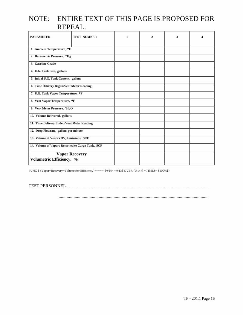
FORM 1 Phase I Vapor Recovery Data Sheet
STATION ID ........................................................................................................................................................................................................................
ADDRESS ...................................................................................................................................... CITY .........................................................................
CONTACT......................................................PHONED............................................... DATE ......................................................................................
Number of Underground Tanks ..................Vapor Return Manifold (Y/N)............ P - Dry Bake Closed .............................................................
Number of Vent Pipes....................................Vent Manifold (Y/N)............................ P - Dry Bake Open................................................................
TP - 201.1 Page 15
NOTE: ENTIRE TEXT OF THIS PAGE IS PROPOSED FOR REPEAL.
PARAMETER TEST NUMBER 1 2 3 4
1. Ambient Temperature, oF
2. Barometric Pressure, "Hg
3. Gasoline Grade
4. U.G. Tank Size, gallons
5. Initial U.G. Tank Content, gallons
6. Time Delivery Began/Vent Meter Reading
7. U.G. Tank Vapor Temperature, oF
8. Vent Vapor Temperature, oF
9. Vent Meter Pressure, "H2O
10. Volume Delivered, gallons
11. Time Delivery Ended/Vent Meter Reading
12. Drop Flowrate, gallons per minute
13. Volume of Vent (VOV) Emissions, SCF
14. Volume of Vapors Returned to Cargo Tank, SCF
Vapor Recovery Volumetric Efficiency, %
FUNC { {Vapor~Recovery~Volumetric~Efficiency}~~=~~{{\#14~-~\#13} OVER {\#14}} ~TIMES~ {100%}}
TEST PERSONNEL ............................................................................................................................
...................................................................................................................................
TP - 201.1 Page 16

NOTE: ENTIRE TEXT OF THIS PAGE IS PROPOSED FOR REPEAL.
FORM 2 Phase I Vent Pipe Data Sheet
STATION ID ...................................................................................................................................................................................................................
ADDRESS ..................................................................................................................................CITY ...........................................................................
CONTACT..............................................................................................................PHONE ........................................ DATE.....................................
Number of Underground Tanks ..................Number of Vent Pipes....................................Test Times ..................................................................
Vent Manifold (Y/N)......................................Vapor Return Manifold (Y/N)......................Vent Valve (Y/N) .......................................................
Bulk Drop ID ..................................................Grade(s) Dropped ..........................................Gallons(s) Dropped ...................................................
TIME P
"H2O T oF TIME
VAIR & VAPOR SCF
P "H2O
T oF
1 min 4 min
2 min 5 min
3 min 6 min
TEST PERSONNEL ............................................................................................................................ .. ............................................................................................................................
TP - 201.1 Page 17

NOTE: ENTIRE TEXT OF THIS PAGE IS PROPOSED FOR REPEAL.
FORM 3 Phase I Cargo Tank Data Sheet
STATION ID ........................................................... ............................................................................... ............................................................................
ADDRESS ................................................................ ...............................................................................CITY..................................................................
CONTACT...............................................................PHONE ................................................................DATE.................................................................
Number of Underground Tanks ...........................Number of Vent Pipes ........................................Test Times.........................................................
Vent Manifold (Y/N)...............................................Vapor Return Manifold (Y/N) ..........................Vent Valve (Y/N) ..............................................
Bulk Drop ID ...........................................................Grade(s) Dropped...............................................Gallons(s) Dropped..........................................
TIME VLIQUID FUEL GALLONS
P "H2O
TEMP. oF TIME
VLIQUID FUEL GALLONS
P "H2O
TEMP. oF
1 min 4 min
2 min 5 min
3 min 6 min
TEST PERSONNEL ..........................................................................................................................
...............................................................................................................................................................
TP - 201.1 Page 18

FORM 4 Reporting Results
STATION ID ........................................................... ............................................................................... ..........................................................................
ADDRESS ................................................................ ...............................................................................CITY................................................................
CONTACT...............................................................PHONE ................................................................DATE...............................................................
Summary of Test Results for (Phase I Volumetric Efficiency of
Service Stations)
California Environmental Protection Agency, Air Resources Board: Vapor
Recovery Test Procedure TP-201.1
Determination of Efficiency of Phase I Vapor Recovery Systems of
Dispensing Facilities without Assist Processors
Bulk Drop ID
Volume of Air &Vapor Emitted from Vent, SCF
Volume of Vapors Returned to Cargo Tank, SCF
Individual Vapor Recovery Volumetric Efficiency Test Results, %
Average Vapor Recovery Volumetric Efficiency Test Result, %
Required Vapor Recovery Volumetric Efficiency, % (by Local Regulation)
Compliance Status (circle one) NO YES
Summary of Attachments Indicate Absence in this Column Indicate Number in this Column
Phase I Vapor Recovery Data Sheet(s)
Phase I Vent Pipe Data Sheet(s)
Phase I Cargo Tank Data Sheet(s)
Technical Evaluation and Calculations
Technical Suggestions for Improved Compliance

NOTE: ENTIRE TEXT OF THIS PAGE IS PROPOSED FOR REPEAL.
TP - 201.1 Page 20