Embed Size (px)
Citation preview
STATE COMMITTEE OF THE USSR FOR SUPERVISION OVER SAFE IMPLEMENTATION OF ACTIVITIES IN NUCLEAR-POWER ENGINEERING
(GOSATOMENERGONADZOR OF THE USSR)
RULES AND STANDARDS IN NUCLEAR-POWER ENGINEERING Rules for Arrangement and Safe Operation of Equipme nt and Piping of Nuclear Power
Installations (PNAE G-7-008-89)
2-d edition as amended
Effective since
01.01.90
ALTERATION N 1
To PNAE G-7-008-89 “Rules for Arrangement and Safe Operation of Equipment and Piping of Nuclear Power Installations”
Moscow Energoatomizdat
1990
BBK 31.4 P68 DK 621.039.4:62-78(083.75) Series established in 1987 Rules for design and safe operation of equipment and pipelines of nuclear power installations (PNAE G-7-008-89). 2-nd edition, as amended/Gosatomenergonadzor of the USSR.- M.: Energoatomizdat, 1990. – 168 pp.: fig. – (Rules and Standards in Nuclear Power). Rules contain obligatory requirements for design and operation of equipment and pipelines of nuclear power installations that ensure reliability and safety of these installations. Knowledge of these Rules is obligatory for all workers participating in design, manufacture and assembling of NPP equipment, training and qualification of NPP operational personnel, obtaining of permissions from the supervisory authorities for operation, repair and modernization of NPP equipment.
CONTENTS 1. General Provisions
1.1. Applicability of the Rules 1.2. Documentation 1.3. General requirements to personnel 1.4. Persons responsible for compliance with these Rules
2.Designs
2.1. General requirements 2.2. Equipment 2.3. Pipelines 2.4. Welded joints 2.5. Special requirements for equipment and pipelines of NPI with fast breeder reactors with liquid metal coolant
3. Materials
3.1. General requirements 3.2. Semiproducts 3.3. Fasteners 3.4. New materials
4. Manufacture, mounting
4.1. General requirements 4.2. Methods of manufacture, mounting 4.3. Tolerances 4.4. Thermal treatment
4.5. Quality control of base materials
5. Hydraulic (pneumatic) tests
5.1. General requirements 5.2. Definition of pressure for hydraulic (pneumatic) tests 5.3. Definition of temperature for hydraulic (pneumatic) tests 5.4. Requirements for implementation of hydraulic (pneumatic) tests 5.5. Pneumatic tests 5.6. Programs of hydraulic (pneumatic) tests
5.7. Assessment of the results of hydraulic (pneumatic) tests
6. Requirements for fitting out of equipment and pipelines with accessories and control and measuring instrumentation
6.1. General requirements 6.2. Safety devices 6.3. Equipping with control and measuring devices
7. In-service inspection of metal of equipment and pipelines. General requirements
7.1. General provisions 7.2. Units under inspection 7.3. Inspection methods (techniques) 7.4. Contents of the standard inspection program 7.5. Contents of the working program for the inspection 7.6. Periodicity of inspection 7.7. Special requirements for reference specimens 7.8. Organization of metal inspection
8. Registration and technical examination
8.1. Registration of equipment and pipelines 8.2. Technical examination 8.3. Permission for implementation of commissioning activities and operation of the NPI systems
9. Operation of equipment and pipelines. General requirements
9.1. General provisions 9.2. Special requirements 9.3. General requirements for arranging of repair of equipment and pipelines
10. Control over compliance with the Rules 11. Investigation of accidents, failures and casualties 12. Conclusions Appendix 1. Main terms and definitions Appendix 2. Examples of assigning of equipment and pipelines to Groups A, B and C Appendix 3. Certificate-descriptor of the NPI vessel Appendix 4. Data presented in the certificate-descriptor on the NPI pump
Appendix 5. Certificate on manufacture of component parts and assembly units of the NPI pipelines Appendix 6. Certificate on the mounting of the NPI pipeline Appendix 7. Certificate on mounting (completion) of the vessel Appendix 8. Certificate-descriptor of the NPI pipeline Appendix 9. Base materials (semiproducts) authorized for the use in manufacture of NPI equipment and pipelines Appendix 10. Requirements for technical specifications on semiproducts Appendix 11. Requirements for the use and qualification of materials Appendix 12. Report on the inspection of the faulty assembly unit Appendix 13. Extract from the factory certificate on the inspected faulty assembly unit Appendix 14. Recommendations on improvement of resistance to cyclic failure rate of fasteners.
1. GENERAL PROVISIONS 1.1. Applicability of the Rules 1.1.1.These Rules are applied to vessels functioning under pressure (including hydrostatic pressure) and in vacuum (including reactor vessels, their safety casings and shells, steam generators and heat exchanges), pump cases and accessories and system’s pipelines of NP (NPP, NCGP, NHP, NIHP)1 with water-moderated water-cooled and graphite-moderated water-cooled reactors, fast breeder reactors with liquid metal coolant and installations with research and pilot reactors of the mentioned types (hereinafter vessels, pump cases and fittings are named as equipment and all mentioned NP are named as nuclear power installations) considered among groups of A, B, and C of these Rules. 1.1.2. Requirements of these Rules are not applied to the following components of equipment and pipelines mentioned in article 1.1.1:
1) Fuel elements and fuel assemblies, rods of control and protection systems (CPS) and other structural components inside reactor vessel, process and other channels that bear fissile, absorbing and moderating materials; 2) Pipes and arrangements embedded in equipment, which damage does not result in release of working medium out of this equipment or flow-over through leakproof components separating different media (including media with different parameters); 3) Mechanical and electrical devices located inside equipment (for example, gears of refueling machines, CPS actuators); 4) Components placed to cases of equipment or inside pipelines with a purpose to study operability of these components; 5) Inner metal lining of concrete vessels of research reactors; 6) Equipment cases made of non-metal materials; 7) Turbine casing, reheat isolation valves, overflow pipes within bounds of turbine and steam-extraction pipelines (in case of availability of isolating devices in a pipeline) from the turbine up tol isolating device; 8) Supports and hangers of pipeline equipment; 9) Metal structures and casings sealing inner space of graphite-moderated water cooled reactors including cased graphite stack and components related to it; 10) Metal structures of refueling and washing boxes with equipment located inside them (with exception of plugs sealing refueling channels of the reactor) for fast reactors; 11) Rammed gaskets and non-metal components of seal assemblies; 12) Parts of machines that are not independent vessels (for example, condensers and heat exchangers embedded to machines, etc.).
1.1.3. “Rules for design and safe operation of vessels operated under pressure” and “Rules for design and safe operation of steam and hot water pipelines” issued by Gosgortechnadzor of the UUSR, Construction Standards and Rules (SNiP) and all relevant regulatory documents within a scope of application of the corresponding rules are applied to equipment and pipelines of nuclear power installations (NPI) that are not mentioned in article 1.1.1.
1 NP – nuclear plant, NPP – nuclear power plant, NCGP - nuclear co-generation plant, NHP – nuclear heating plant, NIHP – nuclear plant for industrial heating
1.1.4. Equipment and pipelines that are within a scope of applicability of these Rules are divided into A, B and C groups according to the extent of effect of a system they are parts of on NPI safety. They belong to safety classes 1, 2 and 3 according to classification of “General Provisions for NPP safety (OPB-88)”. 1.1.5. Equipment and pipelines, which damage is an initiating event resulting in excess of fuel element failure limits, established for design basis accidents, in case of design operation of safety systems, belong to group A (first safety class). Reactor vessels and process channels of any NPI also belong to group A independently of consequences of their failures. 1.1.6. Equipment and pipelines, which damage leads to coolant leakage that can not be removed by regular isolating valves and/or requires safety systems actuation belong to group B (second safety class). Equipment and pipelines of NPI with fast reactors operated in the contact with liquid metal coolant also belong to this group independently of consequences of their failures (with exception of equipment and pipelines that belong to group A). 1.1.7. The following equipment and pipelines belong to group C (third safety class):
1) Equipment and pipelines that are not included into groups A and B and which damage results in leak of coolant providing reactor core cooling; 2) Equipment and pipelines, which damage results in failure of one safety system or one of its channels; 3) Equipment and pipelines, which damage leads to release of high-level and intermediate-level radioactive media (according to definition of “Health (Sanitary) Rules for Design and Operation of NPP” – CPAES).
1.1.8. Examples of standard lists of systems that are within the scope of these Rules applicability are presented in the recommended Appendix 2 with indication of groups of equipment and pipelines being parts of the systems. Grouping of piping accessories shall comply with requirements of regulatory document “Accessories for NPP equipment and pipelines. General technical requirements OTT-87”. 1.1.9. Specific nomenclature of equipment and pipelines with indication of their belonging to A, B and C groups and their consideration among safety classes according to “Classification” is determined by the Chief Designer for each NPI unit and each reactor installation. This shall be coordinated with Gosatomenergonadzor of the USSR as a part of “Technical Safety Justification for NPP construction and operation” at the stage of detail design of the reactor installation and design of NPI. 1.1.10. Equipment and pipelines that contain articles (component parts, assembly units) of different groups belong to a group of the highest requirements. 1.1.11. Isolating devices and safety gears are bounds between equipment and/or pipelines of different groups. At the same time devices and gears themselves belong to the group with the highest requirements. Welded joints conjugating equipment and pipelines can act as bounds between them. Isolating devices at the pump intake or, in case of their absence, welded joints of pump branches with pipelines are bounds in systems with pumps supplied from tanks working under atmospheric pressure. 1.1.12. Categories of welded joints are determined according to Technical Standard “Equipment and pipelines of nuclear power installations. Welded joints and claddings. Inspection Rules” (hereinafter IR). Welded joints at the bounds of equipment and/or pipelines of different groups belong to the highest category.
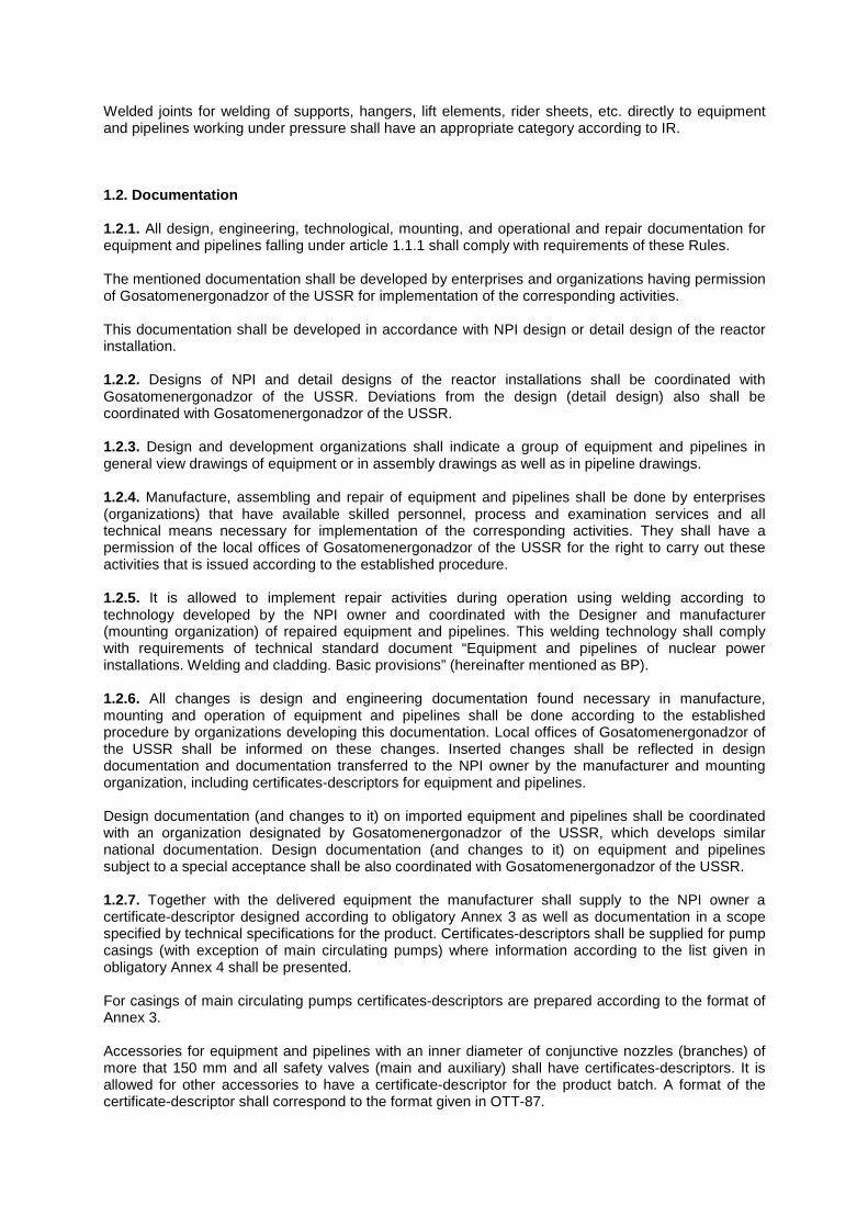
Welded joints for welding of supports, hangers, lift elements, rider sheets, etc. directly to equipment and pipelines working under pressure shall have an appropriate category according to IR. 1.2. Documentation 1.2.1. All design, engineering, technological, mounting, and operational and repair documentation for equipment and pipelines falling under article 1.1.1 shall comply with requirements of these Rules. The mentioned documentation shall be developed by enterprises and organizations having permission of Gosatomenergonadzor of the USSR for implementation of the corresponding activities. This documentation shall be developed in accordance with NPI design or detail design of the reactor installation. 1.2.2. Designs of NPI and detail designs of the reactor installations shall be coordinated with Gosatomenergonadzor of the USSR. Deviations from the design (detail design) also shall be coordinated with Gosatomenergonadzor of the USSR. 1.2.3. Design and development organizations shall indicate a group of equipment and pipelines in general view drawings of equipment or in assembly drawings as well as in pipeline drawings. 1.2.4. Manufacture, assembling and repair of equipment and pipelines shall be done by enterprises (organizations) that have available skilled personnel, process and examination services and all technical means necessary for implementation of the corresponding activities. They shall have a permission of the local offices of Gosatomenergonadzor of the USSR for the right to carry out these activities that is issued according to the established procedure. 1.2.5. It is allowed to implement repair activities during operation using welding according to technology developed by the NPI owner and coordinated with the Designer and manufacturer (mounting organization) of repaired equipment and pipelines. This welding technology shall comply with requirements of technical standard document “Equipment and pipelines of nuclear power installations. Welding and cladding. Basic provisions” (hereinafter mentioned as BP). 1.2.6. All changes is design and engineering documentation found necessary in manufacture, mounting and operation of equipment and pipelines shall be done according to the established procedure by organizations developing this documentation. Local offices of Gosatomenergonadzor of the USSR shall be informed on these changes. Inserted changes shall be reflected in design documentation and documentation transferred to the NPI owner by the manufacturer and mounting organization, including certificates-descriptors for equipment and pipelines. Design documentation (and changes to it) on imported equipment and pipelines shall be coordinated with an organization designated by Gosatomenergonadzor of the USSR, which develops similar national documentation. Design documentation (and changes to it) on equipment and pipelines subject to a special acceptance shall be also coordinated with Gosatomenergonadzor of the USSR. 1.2.7. Together with the delivered equipment the manufacturer shall supply to the NPI owner a certificate-descriptor designed according to obligatory Annex 3 as well as documentation in a scope specified by technical specifications for the product. Certificates-descriptors shall be supplied for pump casings (with exception of main circulating pumps) where information according to the list given in obligatory Annex 4 shall be presented. For casings of main circulating pumps certificates-descriptors are prepared according to the format of Annex 3. Accessories for equipment and pipelines with an inner diameter of conjunctive nozzles (branches) of more that 150 mm and all safety valves (main and auxiliary) shall have certificates-descriptors. It is allowed for other accessories to have a certificate-descriptor for the product batch. A format of the certificate-descriptor shall correspond to the format given in OTT-87.
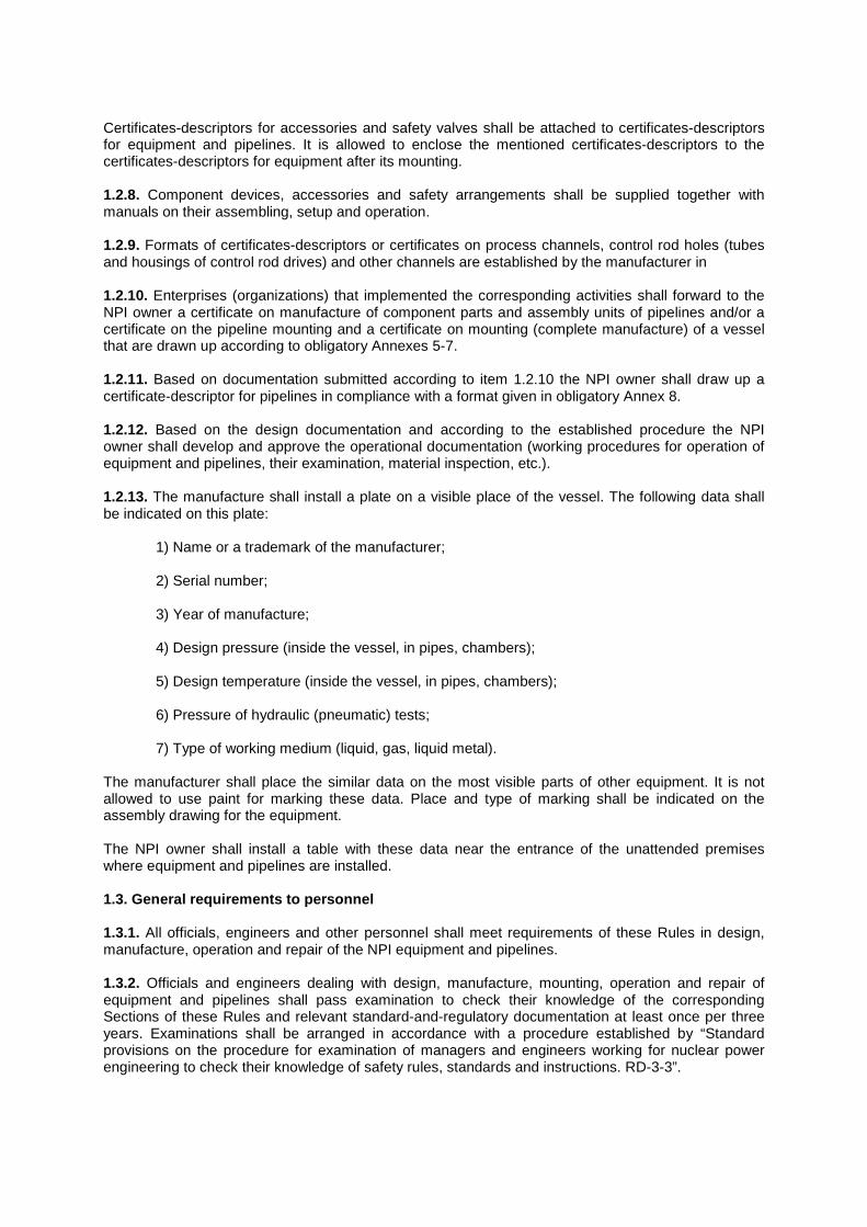
Certificates-descriptors for accessories and safety valves shall be attached to certificates-descriptors for equipment and pipelines. It is allowed to enclose the mentioned certificates-descriptors to the certificates-descriptors for equipment after its mounting. 1.2.8. Component devices, accessories and safety arrangements shall be supplied together with manuals on their assembling, setup and operation. 1.2.9. Formats of certificates-descriptors or certificates on process channels, control rod holes (tubes and housings of control rod drives) and other channels are established by the manufacturer in 1.2.10. Enterprises (organizations) that implemented the corresponding activities shall forward to the NPI owner a certificate on manufacture of component parts and assembly units of pipelines and/or a certificate on the pipeline mounting and a certificate on mounting (complete manufacture) of a vessel that are drawn up according to obligatory Annexes 5-7. 1.2.11. Based on documentation submitted according to item 1.2.10 the NPI owner shall draw up a certificate-descriptor for pipelines in compliance with a format given in obligatory Annex 8. 1.2.12. Based on the design documentation and according to the established procedure the NPI owner shall develop and approve the operational documentation (working procedures for operation of equipment and pipelines, their examination, material inspection, etc.). 1.2.13. The manufacture shall install a plate on a visible place of the vessel. The following data shall be indicated on this plate:
1) Name or a trademark of the manufacturer; 2) Serial number; 3) Year of manufacture; 4) Design pressure (inside the vessel, in pipes, chambers); 5) Design temperature (inside the vessel, in pipes, chambers); 6) Pressure of hydraulic (pneumatic) tests; 7) Type of working medium (liquid, gas, liquid metal).
The manufacturer shall place the similar data on the most visible parts of other equipment. It is not allowed to use paint for marking these data. Place and type of marking shall be indicated on the assembly drawing for the equipment. The NPI owner shall install a table with these data near the entrance of the unattended premises where equipment and pipelines are installed. 1.3. General requirements to personnel 1.3.1. All officials, engineers and other personnel shall meet requirements of these Rules in design, manufacture, operation and repair of the NPI equipment and pipelines. 1.3.2. Officials and engineers dealing with design, manufacture, mounting, operation and repair of equipment and pipelines shall pass examination to check their knowledge of the corresponding Sections of these Rules and relevant standard-and-regulatory documentation at least once per three years. Examinations shall be arranged in accordance with a procedure established by “Standard provisions on the procedure for examination of managers and engineers working for nuclear power engineering to check their knowledge of safety rules, standards and instructions. RD-3-3”.
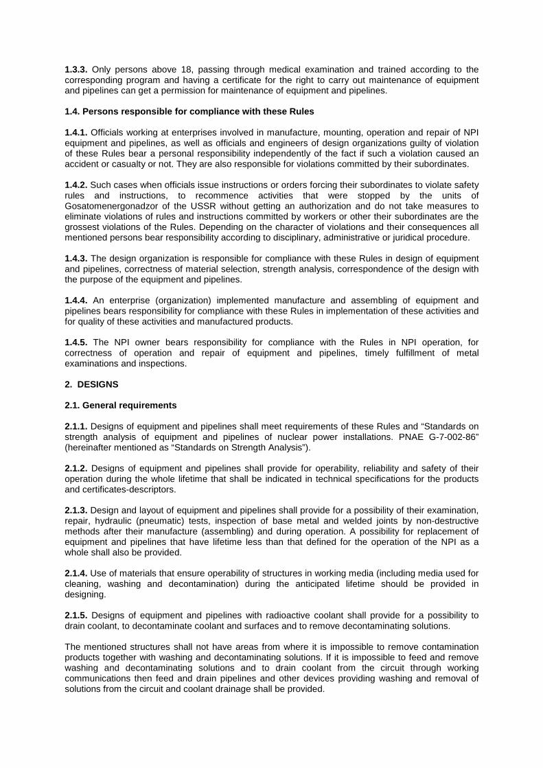
1.3.3. Only persons above 18, passing through medical examination and trained according to the corresponding program and having a certificate for the right to carry out maintenance of equipment and pipelines can get a permission for maintenance of equipment and pipelines. 1.4. Persons responsible for compliance with these Rules 1.4.1. Officials working at enterprises involved in manufacture, mounting, operation and repair of NPI equipment and pipelines, as well as officials and engineers of design organizations guilty of violation of these Rules bear a personal responsibility independently of the fact if such a violation caused an accident or casualty or not. They are also responsible for violations committed by their subordinates. 1.4.2. Such cases when officials issue instructions or orders forcing their subordinates to violate safety rules and instructions, to recommence activities that were stopped by the units of Gosatomenergonadzor of the USSR without getting an authorization and do not take measures to eliminate violations of rules and instructions committed by workers or other their subordinates are the grossest violations of the Rules. Depending on the character of violations and their consequences all mentioned persons bear responsibility according to disciplinary, administrative or juridical procedure. 1.4.3. The design organization is responsible for compliance with these Rules in design of equipment and pipelines, correctness of material selection, strength analysis, correspondence of the design with the purpose of the equipment and pipelines. 1.4.4. An enterprise (organization) implemented manufacture and assembling of equipment and pipelines bears responsibility for compliance with these Rules in implementation of these activities and for quality of these activities and manufactured products. 1.4.5. The NPI owner bears responsibility for compliance with the Rules in NPI operation, for correctness of operation and repair of equipment and pipelines, timely fulfillment of metal examinations and inspections. 2. DESIGNS 2.1. General requirements 2.1.1. Designs of equipment and pipelines shall meet requirements of these Rules and “Standards on strength analysis of equipment and pipelines of nuclear power installations. PNAE G-7-002-86” (hereinafter mentioned as “Standards on Strength Analysis”). 2.1.2. Designs of equipment and pipelines shall provide for operability, reliability and safety of their operation during the whole lifetime that shall be indicated in technical specifications for the products and certificates-descriptors. 2.1.3. Design and layout of equipment and pipelines shall provide for a possibility of their examination, repair, hydraulic (pneumatic) tests, inspection of base metal and welded joints by non-destructive methods after their manufacture (assembling) and during operation. A possibility for replacement of equipment and pipelines that have lifetime less than that defined for the operation of the NPI as a whole shall also be provided. 2.1.4. Use of materials that ensure operability of structures in working media (including media used for cleaning, washing and decontamination) during the anticipated lifetime should be provided in designing. 2.1.5. Designs of equipment and pipelines with radioactive coolant shall provide for a possibility to drain coolant, to decontaminate coolant and surfaces and to remove decontaminating solutions. The mentioned structures shall not have areas from where it is impossible to remove contamination products together with washing and decontaminating solutions. If it is impossible to feed and remove washing and decontaminating solutions and to drain coolant from the circuit through working communications then feed and drain pipelines and other devices providing washing and removal of solutions from the circuit and coolant drainage shall be provided.
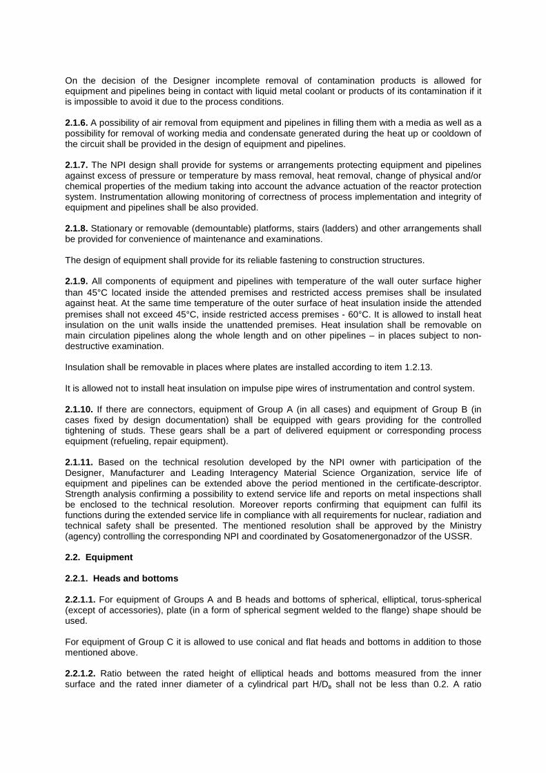
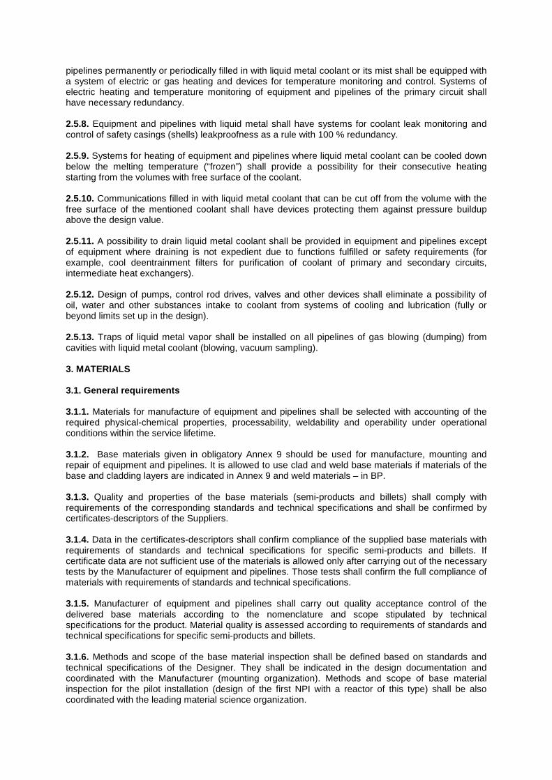
On the decision of the Designer incomplete removal of contamination products is allowed for equipment and pipelines being in contact with liquid metal coolant or products of its contamination if it is impossible to avoid it due to the process conditions. 2.1.6. A possibility of air removal from equipment and pipelines in filling them with a media as well as a possibility for removal of working media and condensate generated during the heat up or cooldown of the circuit shall be provided in the design of equipment and pipelines. 2.1.7. The NPI design shall provide for systems or arrangements protecting equipment and pipelines against excess of pressure or temperature by mass removal, heat removal, change of physical and/or chemical properties of the medium taking into account the advance actuation of the reactor protection system. Instrumentation allowing monitoring of correctness of process implementation and integrity of equipment and pipelines shall be also provided. 2.1.8. Stationary or removable (demountable) platforms, stairs (ladders) and other arrangements shall be provided for convenience of maintenance and examinations. The design of equipment shall provide for its reliable fastening to construction structures. 2.1.9. All components of equipment and pipelines with temperature of the wall outer surface higher than 45°C located inside the attended premises and restricted access premises shall be insulated against heat. At the same time temperature of the outer surface of heat insulation inside the attended premises shall not exceed 45°C, inside restricted access premises - 60°C. It is allowed to install heat insulation on the unit walls inside the unattended premises. Heat insulation shall be removable on main circulation pipelines along the whole length and on other pipelines – in places subject to non-destructive examination. Insulation shall be removable in places where plates are installed according to item 1.2.13. It is allowed not to install heat insulation on impulse pipe wires of instrumentation and control system. 2.1.10. If there are connectors, equipment of Group A (in all cases) and equipment of Group B (in cases fixed by design documentation) shall be equipped with gears providing for the controlled tightening of studs. These gears shall be a part of delivered equipment or corresponding process equipment (refueling, repair equipment). 2.1.11. Based on the technical resolution developed by the NPI owner with participation of the Designer, Manufacturer and Leading Interagency Material Science Organization, service life of equipment and pipelines can be extended above the period mentioned in the certificate-descriptor. Strength analysis confirming a possibility to extend service life and reports on metal inspections shall be enclosed to the technical resolution. Moreover reports confirming that equipment can fulfil its functions during the extended service life in compliance with all requirements for nuclear, radiation and technical safety shall be presented. The mentioned resolution shall be approved by the Ministry (agency) controlling the corresponding NPI and coordinated by Gosatomenergonadzor of the USSR. 2.2. Equipment 2.2.1. Heads and bottoms 2.2.1.1. For equipment of Groups A and B heads and bottoms of spherical, elliptical, torus-spherical (except of accessories), plate (in a form of spherical segment welded to the flange) shape should be used. For equipment of Group C it is allowed to use conical and flat heads and bottoms in addition to those mentioned above. 2.2.1.2. Ratio between the rated height of elliptical heads and bottoms measured from the inner surface and the rated inner diameter of a cylindrical part Н/Dв shall not be less than 0.2. A ratio
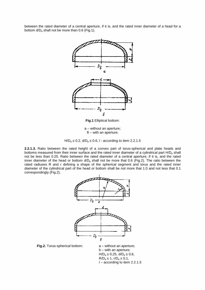
between the rated diameter of a central aperture, if it is, and the rated inner diameter of a head for a bottom d/Dв shall not be more than 0.6 (Fig.1).
Fig.1 Elliptical bottom:
а – without an aperture; б – with an aperture;
Н/Dв ≥ 0.2, d/Dв ≤ 0.6, l - according to item 2.2.1.5
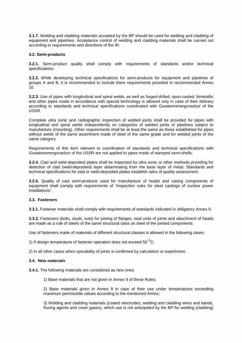
2.2.1.3. Ratio between the rated height of a convex part of torus-spherical and plate heads and bottoms measured from their inner surface and the rated inner diameter of a cylindrical part H/Dв shall not be less than 0.25. Ratio between the rated diameter of a central aperture, if it is, and the rated inner diameter of the head or bottom d/Dв shall not be more that 0.6 (Fig.2). The ratio between the rated radiuses R and r defining a shape of the spherical segment and torus and the rated inner diameter of the cylindrical part of the head or bottom shall be not more that 1.0 and not less that 0.1 correspondingly (Fig.2).
Fig.2. Torus-spherical bottom: а – without an aperture;
b – with an aperture; H/Dв ≥ 0,25, d/Dв ≤ 0,6, R/Dв ≤ 1, r/Dв ≥ 0,1, l – according to item 2.2.1.5
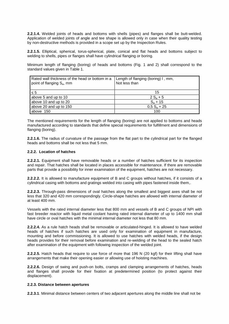
2.2.1.4. Welded joints of heads and bottoms with shells (pipes) and flanges shall be butt-welded. Application of welded joints of angle and tee shape is allowed only in case when their quality testing by non-destructive methods is provided in a scope set up by the Inspection Rules. 2.2.1.5. Elliptical, spherical, torus-spherical, plate, conical and flat heads and bottoms subject to welding to shells, pipes or flanges shall have cylindrical flanging or boring. Minimum length of flanging (boring) of heads and bottoms (Fig. 1 and 2) shall correspond to the standard values given in Table 1.
Rated wall thickness of the head or bottom in a point of flanging Sи, mm
Length of flanging (boring) l , mm, Not less than
≤ 5 15 above 5 and up to 10 2 Sи + 5 above 10 and up to 20 Sи + 15 above 20 and up to 150 0,5 Sи + 25 above 150 100
The mentioned requirements for the length of flanging (boring) are not applied to bottoms and heads manufactured according to standards that define special requirements for fulfillment and dimensions of flanging (boring). 2.2.1.6. The radius of curvature of the passage from the flat part to the cylindrical part for the flanged heads and bottoms shall be not less that 5 mm. 2.2.2. Location of hatches 2.2.2.1. Equipment shall have removable heads or a number of hatches sufficient for its inspection and repair. That hatches shall be located in places accessible for maintenance. If there are removable parts that provide a possibility for inner examination of the equipment, hatches are not necessary. 2.2.2.2. It is allowed to manufacture equipment of B and C groups without hatches, if it consists of a cylindrical casing with bottoms and gratings welded into casing with pipes fastened inside them,. 2.2.2.3. Through-pass dimensions of oval hatches along the smallest and biggest axes shall be not less that 320 and 420 mm correspondingly. Circle-shape hatches are allowed with internal diameter of at least 400 mm. Vessels with the rated internal diameter less that 800 mm and vessels of B and C groups of NPI with fast breeder reactor with liquid metal coolant having rated internal diameter of up to 1400 mm shall have circle or oval hatches with the minimal internal diameter not less that 80 mm. 2.2.2.4. As a rule hatch heads shall be removable or articulated-hinged. It is allowed to have welded heads of hatches if such hatches are used only for examination of equipment in manufacture, mounting and before commissioning. It is allowed to use hatches with welded heads, if the design heads provides for their removal before examination and re-welding of the head to the sealed hatch after examination of the equipment with following inspection of the welded joint. 2.2.2.5. Hatch heads that require to use force of more that 196 N (20 kgf) for their lifting shall have arrangements that make their opening easier or allowing use of hoisting machines. 2.2.2.6. Design of swing and push-on bolts, cramps and clamping arrangements of hatches, heads and flanges shall provide for their fixation at predetermined position (to protect against their displacement). 2.2.3. Distance between apertures 2.2.3.1. Minimal distance between centers of two adjacent apertures along the middle line shall not be
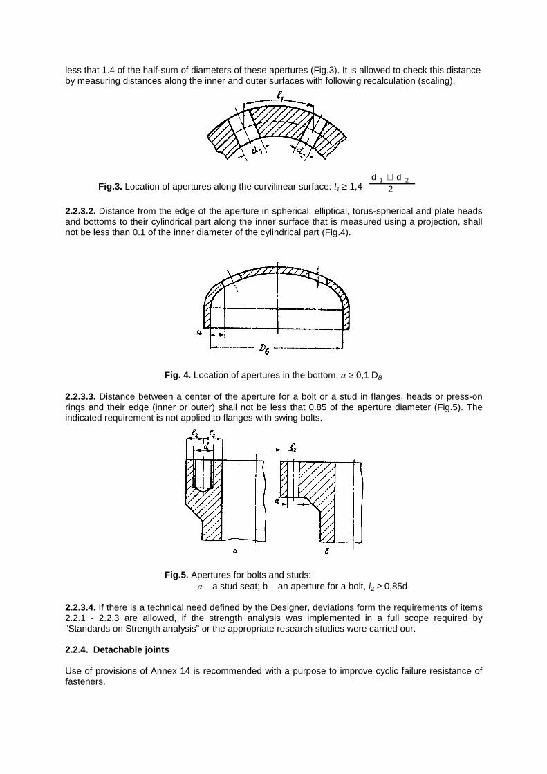
less that 1.4 of the half-sum of diameters of these apertures (Fig.3). It is allowed to check this distance by measuring distances along the inner and outer surfaces with following recalculation (scaling).
Fig.3. Location of apertures along the curvilinear surface: l1 ≥ 1,4 d d
21 2+
2.2.3.2. Distance from the edge of the aperture in spherical, elliptical, torus-spherical and plate heads and bottoms to their cylindrical part along the inner surface that is measured using a projection, shall not be less than 0.1 of the inner diameter of the cylindrical part (Fig.4).
Fig. 4. Location of apertures in the bottom, а ≥ 0,1 DВ
2.2.3.3. Distance between a center of the aperture for a bolt or a stud in flanges, heads or press-on rings and their edge (inner or outer) shall not be less that 0.85 of the aperture diameter (Fig.5). The indicated requirement is not applied to flanges with swing bolts.
Fig.5. Apertures for bolts and studs:
а – a stud seat; b – an aperture for a bolt, l2 ≥ 0,85d 2.2.3.4. If there is a technical need defined by the Designer, deviations form the requirements of items 2.2.1 - 2.2.3 are allowed, if the strength analysis was implemented in a full scope required by “Standards on Strength analysis” or the appropriate research studies were carried our. 2.2.4. Detachable joints Use of provisions of Annex 14 is recommended with a purpose to improve cyclic failure resistance of fasteners.
2.3. Pipelines 2.3.1. Connection of component parts and assembly units of pipelines between each other and connection of pipelines to equipment shall be welded. Use of detachable flange joints of pipelines (including threaded joints with a seal of a ball and a cone) is allowed if their necessity is defined by requirements for maintenance of equipment and pipelines. 2.3.2. Thermal expansions of pipelines can be compensated both by their self-compensation and with a help of special compensating expansion devices. Use of lens compensating expansion devices is allowed only for pipelines operating under working pressure up to 2,45 MPa (24 kgf/cm2 ). 2.3.3. The average radius of pipeline bend curvature shall be equal to:
1) Not less that 3.5 of the rated outer diameter of the elbow (normally bent elbows) – in case of manufacture by cold bending method; 2) Not less than the rated outer diameter of the elbow (steeply bend elbows, if the average diameter of their curvature is less than the rated outer diameter of the elbow) – in case of manufacture by hot straining methods with bending, broach, stamping, slump, and for the stamped-welded elbows.
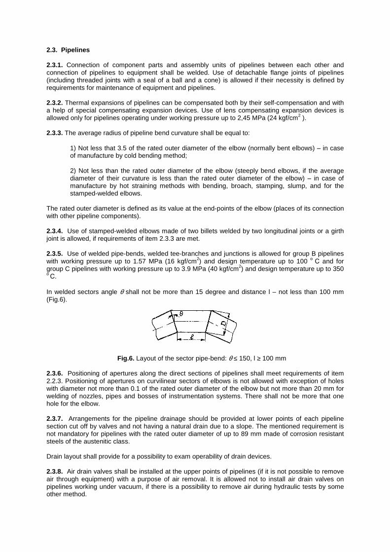
The rated outer diameter is defined as its value at the end-points of the elbow (places of its connection with other pipeline components). 2.3.4. Use of stamped-welded elbows made of two billets welded by two longitudinal joints or a girth joint is allowed, if requirements of item 2.3.3 are met. 2.3.5. Use of welded pipe-bends, welded tee-branches and junctions is allowed for group B pipelines with working pressure up to 1.57 MPa (16 kgf/cm2) and design temperature up to 100 о
С and for group C pipelines with working pressure up to 3.9 MPa (40 kgf/cm2) and design temperature up to 350 о С.
In welded sectors angle θ shall not be more than 15 degree and distance l – not less than 100 mm (Fig.6).
Fig.6. Layout of the sector pipe-bend: θ ≤ 150, l ≥ 100 mm
2.3.6. Positioning of apertures along the direct sections of pipelines shall meet requirements of item 2.2.3. Positioning of apertures on curvilinear sectors of elbows is not allowed with exception of holes with diameter not more than 0.1 of the rated outer diameter of the elbow but not more than 20 mm for welding of nozzles, pipes and bosses of instrumentation systems. There shall not be more that one hole for the elbow. 2.3.7. Arrangements for the pipeline drainage should be provided at lower points of each pipeline section cut off by valves and not having a natural drain due to a slope. The mentioned requirement is not mandatory for pipelines with the rated outer diameter of up to 89 mm made of corrosion resistant steels of the austenitic class. Drain layout shall provide for a possibility to exam operability of drain devices. 2.3.8. Air drain valves shall be installed at the upper points of pipelines (if it is not possible to remove air through equipment) with a purpose of air removal. It is allowed not to install air drain valves on pipelines working under vacuum, if there is a possibility to remove air during hydraulic tests by some other method.
2.3.9. Two stop valves shall be installed at drain pipelines and air drain lines of circuits with radioactive coolant. Installation of one throttle and one stop valve as air drain devices is allowed. Combination of air removal lines and drain lines to the common pipeline after the first stop valves is allowed if a common stop device would be installed at this pipeline. It is allowed to combine lines for air removal from those sections of equipment and pipelines that can not be cut off from each other after the point where throttle valves are installed. 2.3.10. All sections of steam pipelines that can be cut off by stop devices shall be equipped with by a nozzle with a valve at the end points with a purpose to provide warm-up and blowdown. If working pressure is higher than 2.15 MPa (22 kgf/cm2) and on pipelines of B group independently on pressure a nozzle with two series valves, stop and throttle, shall be installed. If a steam pipeline is warmed up in two directions, blowdown from both end-points of section shall be provided. 2.3.11. Level sections of pipelines shall have a slop not less than 0.004 to the side of the arrange drainage. For steam pipelines the mentioned slop shall be retained under temperature equal to steam saturation temperature under working pressure. Absence of a slop at the level sections of pipelines with the rated outer diameter up to 60 mm made of austenitic corrosion resistant steels, that work in a contact with water, water-steam mixture and steam, is allowed if pipeline flushing id provided. Absence of a slop at the level sections of pipelines with the rated outer diameter more than 60 mm made of the same structural class steels or plated pearlitic steels and working in the contact with the same media is allowed if a ratio between the length of these sections and the rated internal diameter of the pipeline does not exceed 25. 2.3.12. Continual removal of condensate shall be provided for pipelines of saturated steam and for dead legs of superheated steam pipelines. 2.4. Welded joints 2.4.1. General requirements 2.4.1.1. Welding and cladding shall be done in compliance with requirements and directives of BP. 2.4.1.2. Butt-welded joints shall be done with a full penetration. Note. Welded joints with steel livers (including those with jar washers) are considered as joints with full penetration. 2.4.1.3. Angular welded joints with a constructive clearance are allowed in case of their locations in areas that are not affected by external power bending loads. For example, in case of pipes welding into tube plate, welding of process channels to standpipes, welding of protecting anticorrosive jackets and measuring devices to casings, etc.). They are also allowed to be used if special holders, supports, bundles and other engineering solutions relieving welded joints of the mentioned loads are available. 2.4.1.4. T-shaped welded joints with a constructive clearance are allowed for welding of holders and auxiliary component parts (hangers, cramps, reinforcement plates) to equipment and pipelines and also for welding of guide ribs in accessories (the last one only under design pressure that is not more than 4,9 MPa (50 kgf/cm2)). 2.4.1.5. Overlapping welding joints are allowed for welding of reinforcing straps, base plates, rider sheets, plates, lathes for landing, stairs, corbels, membranes, etc. to equipment and pipelines. Rings welded on the inside of equipment and reinforcing apertures of hatches, nozzles, etc. shall have telltale openings to check integrity. 2.4.1.6. Graded junction from one component to the other shall be provided in butt-welded joints of components with different rated wall thickness. Specific shapes of the mentioned junction shall be fixed by the Designer based on the requirements of strength analysis and a necessity to proved inspection of welded joints by all methods provided.
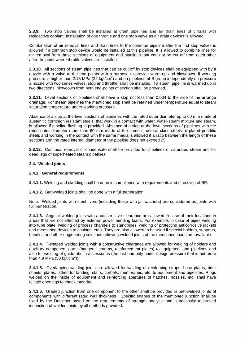
2.4.2. Location of welded joints 2.4.2.1. Manufacture of welded pipes and shells with the rated outer diameter up to 920 mm with longitudinal welds from three or more sectors is not allowed. In case of manufacture of pipes and shells from two sectors the central angle of the small sector shall not be less than 90 О (Fig.7).
Fig.7. A pipe made of two sectors: а - α ≥ 90о – is allowed; b - α < 90о – is not allowed
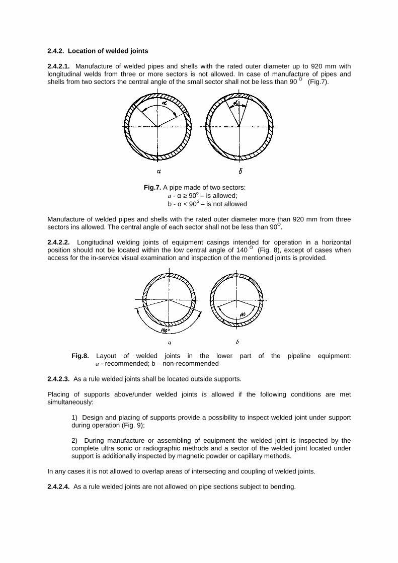
Manufacture of welded pipes and shells with the rated outer diameter more than 920 mm from three sectors ins allowed. The central angle of each sector shall not be less than 90О. 2.4.2.2. Longitudinal welding joints of equipment casings intended for operation in a horizontal position should not be located within the low central angle of 140 О (Fig. 8), except of cases when access for the in-service visual examination and inspection of the mentioned joints is provided.
Fig.8. Layout of welded joints in the lower part of the pipeline equipment: а - recommended; b – non-recommended
2.4.2.3. As a rule welded joints shall be located outside supports. Placing of supports above/under welded joints is allowed if the following conditions are met simultaneously:
1) Design and placing of supports provide a possibility to inspect welded joint under support during operation (Fig. 9); 2) During manufacture or assembling of equipment the welded joint is inspected by the complete ultra sonic or radiographic methods and a sector of the welded joint located under support is additionally inspected by magnetic powder or capillary methods.
In any cases it is not allowed to overlap areas of intersecting and coupling of welded joints. 2.4.2.4. As a rule welded joints are not allowed on pipe sections subject to bending.
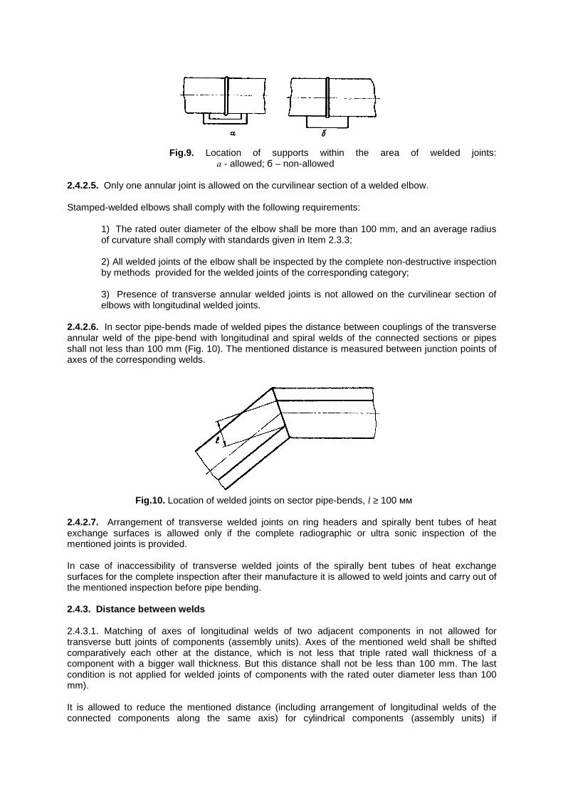
Fig.9. Location of supports within the area of welded joints:
а - allowed; б – non-allowed 2.4.2.5. Only one annular joint is allowed on the curvilinear section of a welded elbow. Stamped-welded elbows shall comply with the following requirements:
1) The rated outer diameter of the elbow shall be more than 100 mm, and an average radius of curvature shall comply with standards given in Item 2.3.3; 2) All welded joints of the elbow shall be inspected by the complete non-destructive inspection by methods provided for the welded joints of the corresponding category; 3) Presence of transverse annular welded joints is not allowed on the curvilinear section of elbows with longitudinal welded joints.
2.4.2.6. In sector pipe-bends made of welded pipes the distance between couplings of the transverse annular weld of the pipe-bend with longitudinal and spiral welds of the connected sections or pipes shall not less than 100 mm (Fig. 10). The mentioned distance is measured between junction points of axes of the corresponding welds.
Fig.10. Location of welded joints on sector pipe-bends, l ≥ 100 мм
2.4.2.7. Arrangement of transverse welded joints on ring headers and spirally bent tubes of heat exchange surfaces is allowed only if the complete radiographic or ultra sonic inspection of the mentioned joints is provided. In case of inaccessibility of transverse welded joints of the spirally bent tubes of heat exchange surfaces for the complete inspection after their manufacture it is allowed to weld joints and carry out of the mentioned inspection before pipe bending. 2.4.3. Distance between welds 2.4.3.1. Matching of axes of longitudinal welds of two adjacent components in not allowed for transverse butt joints of components (assembly units). Axes of the mentioned weld shall be shifted comparatively each other at the distance, which is not less that triple rated wall thickness of a component with a bigger wall thickness. But this distance shall not be less than 100 mm. The last condition is not applied for welded joints of components with the rated outer diameter less than 100 mm). It is allowed to reduce the mentioned distance (including arrangement of longitudinal welds of the connected components along the same axis) for cylindrical components (assembly units) if
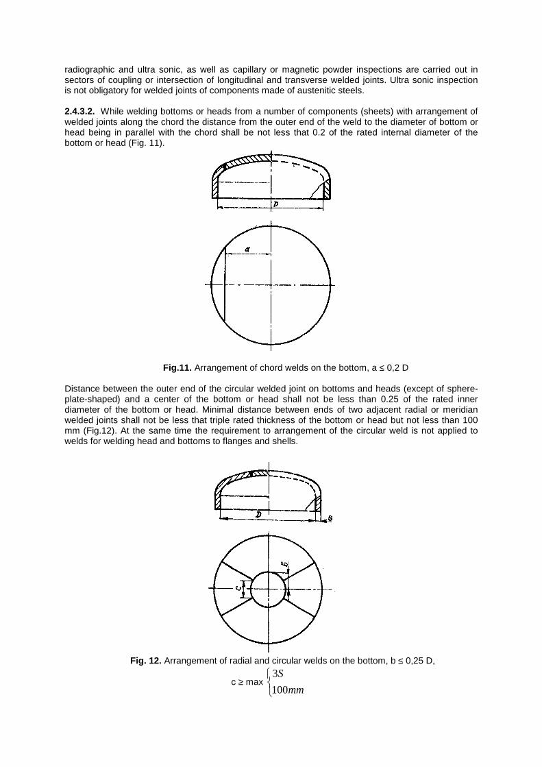
radiographic and ultra sonic, as well as capillary or magnetic powder inspections are carried out in sectors of coupling or intersection of longitudinal and transverse welded joints. Ultra sonic inspection is not obligatory for welded joints of components made of austenitic steels. 2.4.3.2. While welding bottoms or heads from a number of components (sheets) with arrangement of welded joints along the chord the distance from the outer end of the weld to the diameter of bottom or head being in parallel with the chord shall be not less that 0.2 of the rated internal diameter of the bottom or head (Fig. 11).
Fig.11. Arrangement of chord welds on the bottom, a ≤ 0,2 D Distance between the outer end of the circular welded joint on bottoms and heads (except of sphere-plate-shaped) and a center of the bottom or head shall not be less than 0.25 of the rated inner diameter of the bottom or head. Minimal distance between ends of two adjacent radial or meridian welded joints shall not be less that triple rated thickness of the bottom or head but not less than 100 mm (Fig.12). At the same time the requirement to arrangement of the circular weld is not applied to welds for welding head and bottoms to flanges and shells.
Fig. 12. Arrangement of radial and circular welds on the bottom, b ≤ 0,25 D,
с ≥ max
mm
S
100
3
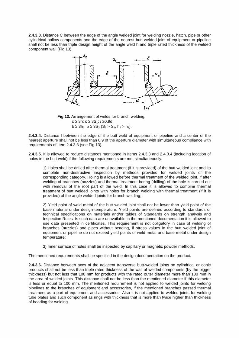
2.4.3.3. Distance C between the edge of the angle welded joint for welding nozzle, hatch, pipe or other cylindrical hollow components and the edge of the nearest butt welded joint of equipment or pipeline shall not be less than triple design height of the angle weld h and triple rated thickness of the welded component wall (Fig.13).
Fig.13. Arrangement of welds for branch welding,
c ≥ 3h; c ≥ 3S1; l ≥0,9d; b ≥ 3h2; b ≥ 3S2 (S2 > S1, h2 > h1).
2.4.3.4. Distance l between the edge of the butt weld of equipment or pipeline and a center of the nearest aperture shall not be less than 0.9 of the aperture diameter with simultaneous compliance with requirements of Item 2.4.3.3 (see Fig.13). 2.4.3.5. It is allowed to reduce distances mentioned in Items 2.4.3.3 and 2.4.3.4 (including location of holes in the butt weld) if the following requirements are met simultaneously:
1) Holes shall be drilled after thermal treatment (if it is provided) of the butt welded joint and its complete non-destructive inspection by methods provided for welded joints of the corresponding category. Holing is allowed before thermal treatment of the welded joint, if after welding of branches (nozzles) and thermal treatment boring (drilling) of the hole is carried out with removal of the root part of the weld. In this case it is allowed to combine thermal treatment of butt welded joints with holes for branch welding with thermal treatment (if it is provided) of the angle welded joints for branch welding;
2) Yield point of weld metal of the butt welded joint shall not be lower than yield point of the base material under design temperature. Yield points are defined according to standards or technical specifications on materials and/or tables of Standards on strength analysis and Inspection Rules. Is such data are unavailable in the mentioned documentation it is allowed to use data presented in certificates. This requirement is not obligatory in case of welding of branches (nuzzles) and pipes without beading, if stress values in the butt welded joint of equipment or pipeline do not exceed yield points of weld metal and base metal under design temperature; 3) Inner surface of holes shall be inspected by capillary or magnetic powder methods.
The mentioned requirements shall be specified in the design documentation on the product. 2.4.3.6. Distance between axes of the adjacent transverse butt-welded joints on cylindrical or conic products shall not be less than triple rated thickness of the wall of welded components (by the bigger thickness) but not less that 100 mm for products with the rated outer diameter more than 100 mm in the area of welded joints. This distance shall not be less than the mentioned diameter if this diameter is less or equal to 100 mm. The mentioned requirement is not applied to welded joints for welding pipelines to the branches of equipment and accessories, if the mentioned branches passed thermal treatment as a part of equipment and accessories. Also it is not applied to welded joints for welding tube plates and such component as rings with thickness that is more than twice higher than thickness of beading for welding.
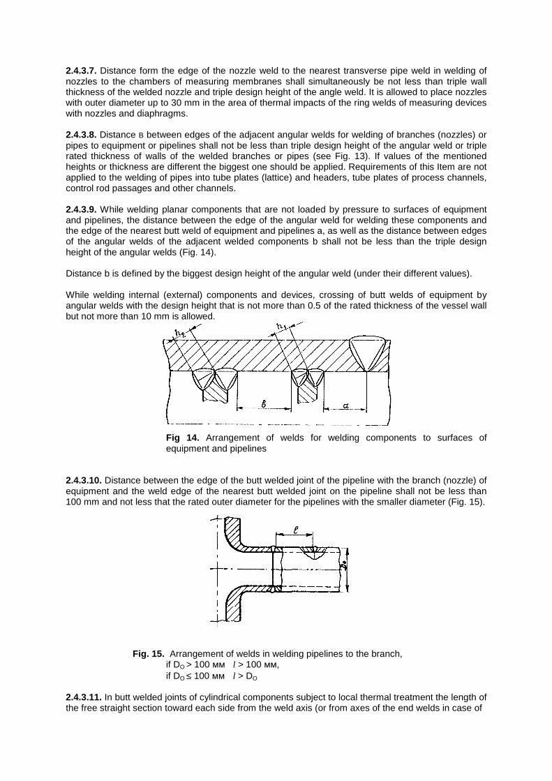
2.4.3.7. Distance form the edge of the nozzle weld to the nearest transverse pipe weld in welding of nozzles to the chambers of measuring membranes shall simultaneously be not less than triple wall thickness of the welded nozzle and triple design height of the angle weld. It is allowed to place nozzles with outer diameter up to 30 mm in the area of thermal impacts of the ring welds of measuring devices with nozzles and diaphragms. 2.4.3.8. Distance B between edges of the adjacent angular welds for welding of branches (nozzles) or pipes to equipment or pipelines shall not be less than triple design height of the angular weld or triple rated thickness of walls of the welded branches or pipes (see Fig. 13). If values of the mentioned heights or thickness are different the biggest one should be applied. Requirements of this Item are not applied to the welding of pipes into tube plates (lattice) and headers, tube plates of process channels, control rod passages and other channels. 2.4.3.9. While welding planar components that are not loaded by pressure to surfaces of equipment and pipelines, the distance between the edge of the angular weld for welding these components and the edge of the nearest butt weld of equipment and pipelines a, as well as the distance between edges of the angular welds of the adjacent welded components b shall not be less than the triple design height of the angular welds (Fig. 14). Distance b is defined by the biggest design height of the angular weld (under their different values). While welding internal (external) components and devices, crossing of butt welds of equipment by angular welds with the design height that is not more than 0.5 of the rated thickness of the vessel wall but not more than 10 mm is allowed.
Fig 14. Arrangement of welds for welding components to surfaces of equipment and pipelines
2.4.3.10. Distance between the edge of the butt welded joint of the pipeline with the branch (nozzle) of equipment and the weld edge of the nearest butt welded joint on the pipeline shall not be less than 100 mm and not less that the rated outer diameter for the pipelines with the smaller diameter (Fig. 15).
Fig. 15. Arrangement of welds in welding pipelines to the branch, if DO > 100 мм l > 100 мм, if DO ≤ 100 мм l > DO
2.4.3.11. In butt welded joints of cylindrical components subject to local thermal treatment the length of the free straight section toward each side from the weld axis (or from axes of the end welds in case of
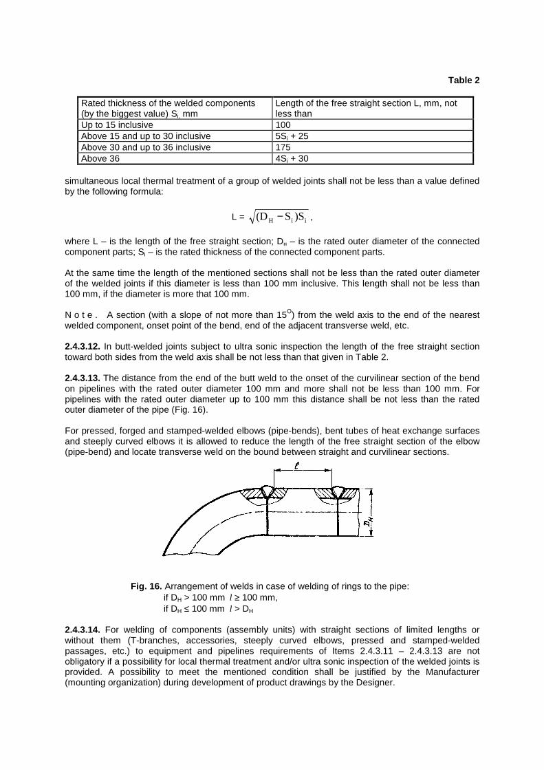
Table 2
Rated thickness of the welded components (by the biggest value) Si, mm
Length of the free straight section L, mm, not less than
Up to 15 inclusive 100 Above 15 and up to 30 inclusive 5Si + 25 Above 30 and up to 36 inclusive 175 Above 36 4Si + 30
simultaneous local thermal treatment of a group of welded joints shall not be less than a value defined by the following formula:
L = iiH )SS(D − ,
where L – is the length of the free straight section; Dн – is the rated outer diameter of the connected component parts; Si – is the rated thickness of the connected component parts. At the same time the length of the mentioned sections shall not be less than the rated outer diameter of the welded joints if this diameter is less than 100 mm inclusive. This length shall not be less than 100 mm, if the diameter is more that 100 mm. N o t e . A section (with a slope of not more than 15О) from the weld axis to the end of the nearest welded component, onset point of the bend, end of the adjacent transverse weld, etc. 2.4.3.12. In butt-welded joints subject to ultra sonic inspection the length of the free straight section toward both sides from the weld axis shall be not less than that given in Table 2. 2.4.3.13. The distance from the end of the butt weld to the onset of the curvilinear section of the bend on pipelines with the rated outer diameter 100 mm and more shall not be less than 100 mm. For pipelines with the rated outer diameter up to 100 mm this distance shall be not less than the rated outer diameter of the pipe (Fig. 16). For pressed, forged and stamped-welded elbows (pipe-bends), bent tubes of heat exchange surfaces and steeply curved elbows it is allowed to reduce the length of the free straight section of the elbow (pipe-bend) and locate transverse weld on the bound between straight and curvilinear sections.
Fig. 16. Arrangement of welds in case of welding of rings to the pipe: if DH > 100 mm l ≥ 100 mm, if DH ≤ 100 mm l > DH
2.4.3.14. For welding of components (assembly units) with straight sections of limited lengths or without them (T-branches, accessories, steeply curved elbows, pressed and stamped-welded passages, etc.) to equipment and pipelines requirements of Items 2.4.3.11 – 2.4.3.13 are not obligatory if a possibility for local thermal treatment and/or ultra sonic inspection of the welded joints is provided. A possibility to meet the mentioned condition shall be justified by the Manufacturer (mounting organization) during development of product drawings by the Designer.
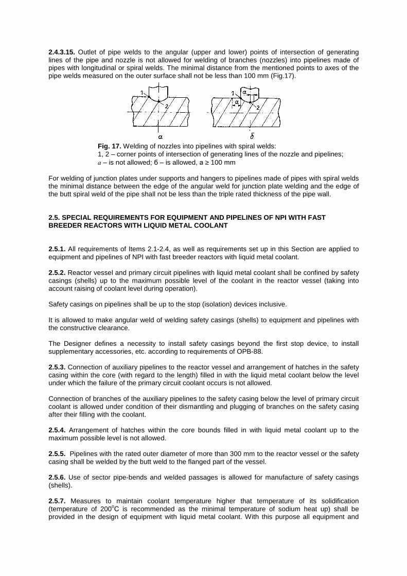
2.4.3.15. Outlet of pipe welds to the angular (upper and lower) points of intersection of generating lines of the pipe and nozzle is not allowed for welding of branches (nozzles) into pipelines made of pipes with longitudinal or spiral welds. The minimal distance from the mentioned points to axes of the pipe welds measured on the outer surface shall not be less than 100 mm (Fig.17).
Fig. 17. Welding of nozzles into pipelines with spiral welds: 1, 2 – corner points of intersection of generating lines of the nozzle and pipelines; а – is not allowed; б – is allowed, а ≥ 100 mm
For welding of junction plates under supports and hangers to pipelines made of pipes with spiral welds the minimal distance between the edge of the angular weld for junction plate welding and the edge of the butt spiral weld of the pipe shall not be less than the triple rated thickness of the pipe wall. 2.5. SPECIAL REQUIREMENTS FOR EQUIPMENT AND PIPELIN ES OF NPI WITH FAST BREEDER REACTORS WITH LIQUID METAL COOLANT 2.5.1. All requirements of Items 2.1-2.4, as well as requirements set up in this Section are applied to equipment and pipelines of NPI with fast breeder reactors with liquid metal coolant. 2.5.2. Reactor vessel and primary circuit pipelines with liquid metal coolant shall be confined by safety casings (shells) up to the maximum possible level of the coolant in the reactor vessel (taking into account raising of coolant level during operation). Safety casings on pipelines shall be up to the stop (isolation) devices inclusive. It is allowed to make angular weld of welding safety casings (shells) to equipment and pipelines with the constructive clearance. The Designer defines a necessity to install safety casings beyond the first stop device, to install supplementary accessories, etc. according to requirements of OPB-88. 2.5.3. Connection of auxiliary pipelines to the reactor vessel and arrangement of hatches in the safety casing within the core (with regard to the length) filled in with the liquid metal coolant below the level under which the failure of the primary circuit coolant occurs is not allowed. Connection of branches of the auxiliary pipelines to the safety casing below the level of primary circuit coolant is allowed under condition of their dismantling and plugging of branches on the safety casing after their filling with the coolant. 2.5.4. Arrangement of hatches within the core bounds filled in with liquid metal coolant up to the maximum possible level is not allowed. 2.5.5. Pipelines with the rated outer diameter of more than 300 mm to the reactor vessel or the safety casing shall be welded by the butt weld to the flanged part of the vessel. 2.5.6. Use of sector pipe-bends and welded passages is allowed for manufacture of safety casings (shells). 2.5.7. Measures to maintain coolant temperature higher that temperature of its solidification (temperature of 200оС is recommended as the minimal temperature of sodium heat up) shall be provided in the design of equipment with liquid metal coolant. With this purpose all equipment and
pipelines permanently or periodically filled in with liquid metal coolant or its mist shall be equipped with a system of electric or gas heating and devices for temperature monitoring and control. Systems of electric heating and temperature monitoring of equipment and pipelines of the primary circuit shall have necessary redundancy. 2.5.8. Equipment and pipelines with liquid metal shall have systems for coolant leak monitoring and control of safety casings (shells) leakproofness as a rule with 100 % redundancy. 2.5.9. Systems for heating of equipment and pipelines where liquid metal coolant can be cooled down below the melting temperature (“frozen”) shall provide a possibility for their consecutive heating starting from the volumes with free surface of the coolant. 2.5.10. Communications filled in with liquid metal coolant that can be cut off from the volume with the free surface of the mentioned coolant shall have devices protecting them against pressure buildup above the design value. 2.5.11. A possibility to drain liquid metal coolant shall be provided in equipment and pipelines except of equipment where draining is not expedient due to functions fulfilled or safety requirements (for example, cool deentrainment filters for purification of coolant of primary and secondary circuits, intermediate heat exchangers). 2.5.12. Design of pumps, control rod drives, valves and other devices shall eliminate a possibility of oil, water and other substances intake to coolant from systems of cooling and lubrication (fully or beyond limits set up in the design). 2.5.13. Traps of liquid metal vapor shall be installed on all pipelines of gas blowing (dumping) from cavities with liquid metal coolant (blowing, vacuum sampling). 3. MATERIALS 3.1. General requirements 3.1.1. Materials for manufacture of equipment and pipelines shall be selected with accounting of the required physical-chemical properties, processability, weldability and operability under operational conditions within the service lifetime. 3.1.2. Base materials given in obligatory Annex 9 should be used for manufacture, mounting and repair of equipment and pipelines. It is allowed to use clad and weld base materials if materials of the base and cladding layers are indicated in Annex 9 and weld materials – in BP. 3.1.3. Quality and properties of the base materials (semi-products and billets) shall comply with requirements of the corresponding standards and technical specifications and shall be confirmed by certificates-descriptors of the Suppliers. 3.1.4. Data in the certificates-descriptors shall confirm compliance of the supplied base materials with requirements of standards and technical specifications for specific semi-products and billets. If certificate data are not sufficient use of the materials is allowed only after carrying out of the necessary tests by the Manufacturer of equipment and pipelines. Those tests shall confirm the full compliance of materials with requirements of standards and technical specifications. 3.1.5. Manufacturer of equipment and pipelines shall carry out quality acceptance control of the delivered base materials according to the nomenclature and scope stipulated by technical specifications for the product. Material quality is assessed according to requirements of standards and technical specifications for specific semi-products and billets. 3.1.6. Methods and scope of the base material inspection shall be defined based on standards and technical specifications of the Designer. They shall be indicated in the design documentation and coordinated with the Manufacturer (mounting organization). Methods and scope of base material inspection for the pilot installation (design of the first NPI with a reactor of this type) shall be also coordinated with the leading material science organization.
3.1.7. Welding and cladding materials accepted by the BP should be used for welding and cladding of equipment and pipelines. Acceptance control of welding and cladding materials shall be carried out according to requirements and directions of the IR. 3.2. Semi-products 3.2.1. Semi-product quality shall comply with requirements of standards and/or technical specifications. 3.2.2. While developing technical specifications for semi-products for equipment and pipelines of groups A and B, it is recommended to include there requirements provided in recommended Annex 10. 3.2.3. Use of pipes with longitudinal and spiral welds, as well as forged-drilled, spun-casted, bimetallic and other pipes made in accordance with special technology is allowed only in case of their delivery according to standards and technical specifications coordinated with Gosatomenergonadzor of the USSR. Complete ultra sonic and radiographic inspection of welded joints shall be provided for pipes with longitudinal and spiral welds independently on categories of welded joints of pipelines subject to manufacture (mounting). Other requirements shall be at least the same as those established for pipes without welds of the same assortment made of steel of the same grade and for welded joints of the same category. Requirements of this item relevant to coordination of standards and technical specifications with Gosatomenergonadzor of the USSR are not applied to pipes made of stamped semi-shells. 3.2.4. Clad and weld-deposited plates shall be inspected by ultra sonic or other methods providing for detection of clad (weld-deposited) layer delaminating from the base layer of metal. Standards and technical specifications for clad or weld-deposited plates establish rates of quality assessment. 3.2.5. Quality of cast semi-products used for manufacture of heads and casing components of equipment shall comply with requirements of “Inspection rules for steel castings of nuclear power installations”. 3.3. Fasteners 3.3.1. Fastener materials shall comply with requirements of standards indicated in obligatory Annex 9. 3.3.2. Fasteners (bolts, studs, nuts) for joining of flanges, seal units of joints and attachment of heads are made as a rule of steels of the same structural class as steel of the jointed components. Use of fasteners made of materials of different structural classes is allowed in the following cases: 1) If design temperature of fastener operation does not exceed 50 ОС; 2) In all other cases when operability of joints is confirmed by calculation or experiment. 3.4. New materials 3.4.1. The following materials are considered as new ones:
1) Base materials that are not given in Annex 9 of these Rules; 2) Base materials given in Annex 9 in case of their use under temperatures exceeding maximum permissible values according to the mentioned Annex;
3) Welding and cladding materials (coated electrodes, welding and cladding wires and bands, fluxing agents and cover gases), which use is not anticipated by the BP for welding (cladding)
of components made of steels (alloys) of the corresponding grades (composition of grades) in case of application of specific methods of welding (cladding).
3.4.2. Base materials, which grades are given in Annex 9, melted by methods that are not set up by standards and technical specifications mentioned in the Annex (including melting by vacuum-arc or electroslag remelting) are not considered as new materials. 3.4.3. To include new materials to these Rules or BP the ministry (agency) interested in the use of new materials shall submit to Gosatomenergonadzor of the USSR a corresponding proposal. A report containing data on tests and studies of new materials, as well as standards or technical specifications for semi-products and welding (cladding) materials shall accompany this proposal. A list of data that shall be presented in the report is given in obligatory Annex 11. The report shall be coordinated with the leading organization for development of these Rules and with leading interagency metal science organization. 3.4.4. It is allowed to use new materials for manufacture of the specific equipment upon joint engineering resolution of the Designer, leading branch metal science organization and Manufacturer (mounting organization) coordinated with the ministry (agency) being a control body of the Designer and with Gosatomenergonadzor of the USSR. Standards or technical specifications for semi-products and/or welding (cladding) materials and data on process corrosion properties of base material and/or welded joints (clad metal) shall be enclosed to the mentioned resolution. This documentation shall define a possibility to manufacture of equipment and pipelines with ensuring of the required operability. Scope and nomenclature of the presented data from those mentioned in Annex 11 shall be defined by organizations developing the engineering resolution depending on specific operational conditions for equipment and pipelines. 4. MANUFACTURE AND MOUNTING 4.1. General requirements 4.1.1. Use, mounting and repair of equipment and pipelines should be carried out in accordance with the process documentation (process procedures, diagrams of processes, etc.) that regulates scope and order for implementation of all process and control operations. Manufacturer (mounting or repair organization) or a specialized organization engaged by it shall develop this process documentation in compliance with requirements of these Rules and other regulations applied to the corresponding equipment and pipelines, as well as drawings and technical specifications for the product. Process documentation on the mounting of pilot equipment and pipelines as well as amendments to it (including those for the further serial equipment and pipelines) shall be coordinated with the Designer. 4.1.2. Process documentation on smelting and casting of metal, thermal cutting, treatment by pressure, welding, cladding and thermal treatment shall be coordinated with the leading branch metal science organization. Only standard process procedures regulating process of correction of the most frequent (typical) defects shall be coordinated with the leading branch metal science organization to correct defects in the product metal (including those in welded joints and claddings) with the use of welding. The mentioned coordination is not obligatory if process documentation is developed in a full compliance with the branch process standards, guiding technical materials or procedures (if they are available) developed, coordinated and approved according to the established procedure. At the same time branch documents shall contain specific process requirements and directions (including mode of welding, cladding, thermal treatment, etc.) that fully reflect requirements of these Rules and BP. If process procedures are coordinated with the leading branch metal science organization coordination of process diagrams is not required. 4.1.3. The Manufacturer (mounting or repair organization) shall carry out the production technical control during manufacture, mounting and repair in a scope provided by the design, process and
process-control documentation. Results of the mentioned control shall comply with requirements of these Rules, BP, IR and other regulatory and design documentation applied to the controlled equipment and pipelines. 4.1.4. Welding and cladding including all operations on preparation and assembling for welding and cladding, making of welded joints and clad component parts, their following thermal treatment, etc. should be carried out in compliance with requirements and directions of the BP except of cladding by hard alloys (including claddings of sealing surfaces of valves) that shall be done in compliance with requirements of the branch standard-technical documentation and/or OTT-87. Quality control of welded joints and claddings shall be implemented in compliance with requirements and directions of the IR, except of claddings by hard alloys inspected according to branch’s standard-technical documents and/or OTT-87. 4.1.5. Component parts and assembly units shall have marking indicated on the drawing that allows their identification during manufacture. Component parts and assembly units are marked by paints, electrographic or percussion (stamping) methods. Marking of component parts and assembly units made of austenitic steels and iron-nickel alloys by electrographic method is not allowed. Print depth in marking by percussion method shall not exceed 0.3 mm. Edges of the mark shall not have sharp facets. 4.1.6. The manufactured products (assembly units, component parts) shall be cleaned up, preserved and packed (including aperture plugging) before their shipment for mounting in compliance with requirements of technical specifications for the product. 4.1.7. Transport and storage of materials intended for manufacture, mounting and repair of equipment and pipelines, as well as complete equipment and assembly units of equipment and components shall be carried out in compliance with requirements of standards and technical specifications for specific materials, technical specifications for products and corresponding procedures. 4.2. Methods of manufacture and mounting 4.2.1. Cutting of semi-products (billets) and cutting out of apertures shall be done according to technology that avoids crack generation. Mechanical treatment of edges that is provided by process documentation should be carried out after thermal cutting. 4.2.2 Bottoms and heads as well as their component parts should be manufactured by stamping of the one-piece plate or welded plate billet made of the plates previously welded between each other. Use of the mechanized open forging for manufacture of bottoms, heads and their component parts is allowed under condition that their further complete ultra sonic or radiographic inspection will be carried out. 4.2.3. Upset of necks in shells, bottoms, heads and other component parts should be done mechanically. 4.2.4. Enlargement or squeezing of pipe’s ends is allowed during implementation of welded joints with a purpose to provide coupling of their inner surfaces. Cold enlargement (squeezing) is allowed only on pipes, for which the minimal value of relative metal lengthening under temperature of 20 ОС stipulated for by standards or technical specifications is not less than 18 %. At the same time the change of the actual outer diameter of the pipe’s ends shall not be more than 3% of its rated value.
Process documentation determines if hot enlargement (squeezing) of pipe’s ends is allowed and conditions for its implementation. 4.2.5. Coupled surface of the welded component parts (junction plates, stiffening ribs, buckles, hangers, etc.) shall have the same configuration as a surface of the product in places of welding of the mentioned elements. A permissible gap between edge of surface of element subject to welding shall not be less than half of the design height of the angular weld but not more than 5 mm if the design documentation does not state the more strict requirements. 4.2.6. Cold tension of pipelines should be done after implementation of all welded joints on the section of tension (except of the final one), their thermal treatment (if it is provided), quality control of welded joints by all methods provided and final fastening of fixed supports at the ends of tension section. Value of cold tension (distance between ends of the approached pipes) shall be indicated in the design documentation. The mounting organization shall write a report on implementation of the cold tension that is enclosed to the certificate-descriptor of the pipeline. 4.2.7. If component parts with the rated wall thickness less than 8 mm intended for operation under absolute working pressure less than 0.133 Pa (vacuum) or in media containing helium are made of plates, pipes, forged pieces and profiled iron, requirements of the design documentation for fiber location should be met to avoid a possibility of external or internal medium penetration along the fibers of the component part in places of their crosscutting. 4.3. Tolerances 4.3.1. Deviation of the outer diameter and ovality of cylindrical products (except of pipes) made of plates, forged pieces and castings shall not be more than 1 % of its rated value but not more than 20 mm. Increase of the outer diameter deviation and ovality up to 1.5 % of its rated value but not more than 30 mm is allowed at some sections of cylindrical products (assembly units) in places where welded joints are located including places of welding of nozzles (branches), pipes, supports, journals and other elements. The mentioned requirements are valid if technical documentation on the product does not establish smaller values of deviations of the outer diameter and ovality value. Ovality is determined by the following formula:
aD DD D
= −+
2 100%max min
max min
,
where Dmax and Dmin – the biggest and smallest outer diameters of the product measured at the same cross section. 4.3.2. Deviation of outer diameter and ovality of conic products shall comply with requirements of the design documentation. 4.3.3. Deviation of the outer diameter and ovality of cylindrical products made of pipes without supplementary treatment connected with the change of the diameter shall comply with requirements of standards or technical specifications for the used pipes, except of straight sections adjacent to bends along the length equal to two rated outer diameters of the pipe. Deviation of the outer diameter and ovality on the mentioned sections and for the component parts (assembly units) made of pipes with further supplementary treatment connected with the change of the diameter shall comply with requirements of the design documentation.
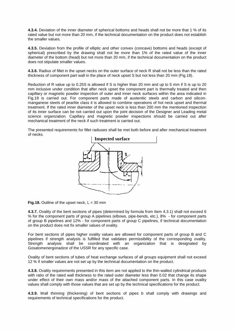
4.3.4. Deviation of the inner diameter of spherical bottoms and heads shall not be more that 1 % of its rated value but not more than 20 mm, if the technical documentation on the product does not establish the smaller values. 4.3.5. Deviation from the profile of elliptic and other convex (concave) bottoms and heads (except of spherical) prescribed by the drawing shall not be more than 1% of the rated value of the inner diameter of the bottom (head) but not more than 20 mm, if the technical documentation on the product does not stipulate smaller values. 4.3.6. Radius of fillet in the upset necks on the outer surface of neck R shall not be less than the rated thickness of component part wall in the place of neck upset S but not less than 20 mm (Fig.18). Reduction of R value up to 0.25S is allowed if S is higher than 20 mm and up to 5 mm if S is up to 20 mm inclusive under condition that after neck upset the component part is thermally treated and then capillary or magnetic powder inspection of outer and inner neck surfaces within the area indicated in Fig.18 is carried out. For component parts made of austenitic steels and carbon and silicon-manganese steels of pearlite class it is allowed to combine operations of hot neck upset and thermal treatment. If the rated inner diameter of the upset neck is less than 200 mm the mentioned inspection of its inner surface can be not carried out upon the joint decision of the Designer and Leading metal science organization. Capillary and magnetic powder inspections should be carried out after mechanical treatment of the neck if such treatment is carried out. The presented requirements for fillet radiuses shall be met both before and after mechanical treatment of necks.
Inspected surface
Fig.18. Outline of the upset neck, L = 30 mm 4.3.7. Ovality of the bent sections of pipes (determined by formula from Item 4.3.1) shall not exceed 6 % for the component parts of group A pipelines (elbows, pipe-bends, etc.), 8% - for component parts of group B pipelines and 12% - for component parts of group C pipelines, if technical documentation on the product does not fix smaller values of ovality. For bent sections of pipes higher ovality values are allowed for component parts of group B and C pipelines if strength analysis is fulfilled that validates permissibility of the corresponding ovality. Strength analysis shall be coordinated with an organization that is designated by Gosatomenergonadzor of the USSR for any specific case. Ovality of bent sections of tubes of heat exchange surfaces of all groups equipment shall not exceed 12 % if smaller values are not set up by the technical documentation on the product. 4.3.8. Ovality requirements presented in this item are not applied to the thin-walled cylindrical products with ratio of the rated wall thickness to the rated outer diameter less than 0.02 that change its shape under effect of their own mass and/or mass of the attached component parts. In this case ovality values shall comply with those values that are set up by the technical specifications for the product. 4.3.9. Wall thinning (thickening) of bent sections of pipes b shall comply with drawings and requirements of technical specifications for the product.
Value of thinning (thickening) is determined by the following formula:
bS S
S= −1 2
1
100% ,
where S1 – actual wall thickness according to measurements of the straight pipe section before bend manufacture; S2 – actual wall thickness according to measurements of the bent section after manufacture. 4.3.10. Height of undulation (crimp) on the inner counter of bent sections of pipes shall not exceed standard values determined by drawings and technical specifications for the product. Width of any crimp shall exceed its height at least in three times. Correction of the unacceptable undulation by mechanical treatment or thermal cutting (gouging) is not allowed. Technology of correction of such undulation by other methods shall be coordinated with the leading metal science organization. It is allowed to correct local asperity at the beginning and at the end of bending by mechanical treatment or thermal cutting (gouging) according to technology coordinated with the leading metal science organization. 4.4. Thermal treatment 4.4.1. Billets, component parts, assembly units and other products should be thermally treated if thermal treatment is stipulated by these Rules, BP, other standard and technical documents, design or process documentation. Need of thermal treatment of assembly units and component parts in the course of manufacture or mounting shall be specified in the design documentation. 4.4.2. Standards or technical specifications for semi-products or products determine a type of thermal treatment (tempering, normalization or hardening with following tempering, austenization, etc.) and its modes (heating rate, temperature and holding duration, cooling conditions, etc.). If the respective directions are not presented in standards or technical specifications they are taken from the process documentation. 4.4.3. Shells, semi-shells, bottoms, heads and other component parts made of carbon and silicon-magnesium steels are subject of thermal treatment after the cold expansion or stamping, if the ratio of the rated wall thickness to the rated inner diameter of the shell (semi-shells) or to the minimal curvature radius of the shell (semi-shell) exceeds 0.05. 4.4.4. Bent sections of pipes made of carbon or silicon-magnesium steels are subject of thermal treatment if ratio of the average bending radius to the rated outer diameter of the pipe is less than 3.5 and the ratio of the rated wall thickness of the pipe to its rated outer diameter exceeds 0.05. 4.4.5. It is allowed not to carry out thermal treatment of component parts made of carbon and silicon-magnesium steels after the hot expansion, bending or stamping, if metal temperature was below 700 ОС at the moment of deformation operation completeness.
4.4.6. In cases that are not indicated in Items 4.4.3 and 4.4.4 standards, drawings of products and process documentation stipulate necessity of thermal treatment of component parts after deformation depending on material properties of the component parts and maximum value of deformation. 4.4.7. In cases stipulate for by the process documentation it is allowed to combine thermal treatment of component parts (assembly units) made of carbon and silicon-magnesium steels and steels of austenitic class after their deformation with the following thermal treatment of the product after two process operations (for example welding).
4.4.8. In course of thermal treatment control over compliance with the modes of heating and holding prescribed by the process documentation with recording of their parameters shall be provided. 4.4.9. During hardening or normalization the product should be place to the thermal furnace entirely. 4.4.10. During tempering and austenization of products with big length its thermal treatment in the furnace by parts according to technology coordinated with the leading metal science organization is allowed. In this case temperature drop of the product metal in the area of heating bound and in the distance of 1 m from the furnace border not more than 100 ОС shall be provided. 4.4.11. Local thermal treatment of the bend section and straight pipe sections adjacent to it with the length that is not less than triple rated thickness of its wall but not less than 100 mm is allowed in tempering and austenization of the bent pipe sections in cases indicated in the design and/or process documentation. 4.4.12. Metal properties of products passed thermal treatment are checked by testing of specimens cut off from overdimension pieces or individual check samples taken from billets. Metal samples shall be taken from the same batch (melt) as the examined product. They shall be thermally treated during manufacture or mounting in the same scope and under the same modes (together with or separately from the examined product) as the product taking into account tempering in cases of metal defect corrections. N o t e . Terms “the same mode of thermal treatment” should be interpreted as thermal treatment of the same type (tempering, normalization or hardening with tempering, austenization, etc.) with the same temperature and holding duration and with accounting of tolerances specified by the process documentation. 4.4.13. It is allowed to reduce holding duration in process tempering of the check sample in comparison with duration specified for the process products but no more than for 20 %. N o t e . Hereinafter term “holding duration” should be interpreted as the rated (average) holding duration specified by the process documentation for the specific tempering. Total holding duration is defined as a sum of rated (average) holding duration stipulated for individual tempering. 4.4.14. If the examined process products are subject of multiple process tempering under the same temperature with the same total holding duration it is allowed to put the check sample to the single tempering under the same temperature with holding duration that is not less than 80% and more than 100% of the total holding duration of the process tempering. 4.4.15. If the examined process products are subject of multiple process tempering under different temperature with the same total holding duration under the same temperature it is allowed to put the check sample to the single tempering under each temperature with holding duration for each temperature that is not less than 80% and more than 100% of the total holding duration of the process tempering. At first the sample is held under the lower temperature and then under the higher one. Time of transient from one temperature to the other is not included into the holding duration. In cases when there are temperings with the same temperature and the same total holding duration among multiple temperings under different temperatures stipulated for the process product, the holding duration of the check sample in course of its single tempering under each of these values of temperature shall not be less than 80% and not more than 100% of the total duration of the corresponding process temperings. 4.4.16. It is allowed to use only one check sample for examination of metal properties if directives of items 4.4.13 – 4.4.15 are observed in cases when the stipulated holding duration (total duration) of process temperings under the same temperature is different but difference between the maximum and minimum holding duration (total duration) does not exceed 20% of the maximum holding duration (total duration). At the same time holding duration in course of check sample tempering shall not be less than 80% and not more than 100% of the maximum holding duration of the process tempering (maximum total holding duration of the corresponding process temperings).
4.4.17. If the examined process products are subject to tempering under different temperature (except of cases mentioned in item 4.4.15) and/or with different holding duration (except of cases mentioned in item 4.4.16) examination of metal properties should be carried out with the use of two individual check samples. The first check sample shall be put to the same tempering (with accounting of directives of items 4.4.13 – 4.4.15) as the process product with the minimal tempering temperature and/or minimal holding duration (in a single tempering) or with the lowest temperature and/or minimal total holding duration under the maximum tempering temperature for the given product (in case of multiple tempering). If among process products there are both products subject to and process tempering and products that shall not put to tempering, the first check sample is not put to tempering. It is allowed not to check metal properties using the first sample if metal properties of billets were inspected before the start of manufacture (mounting) of the process products and complied with the established requirements. The second check sample (according to directives of items 4.4.13 – 4.4.15) shall be put to the same tempering as the process product with the maximum tempering temperature and/or maximum holding duration (in a single tempering) or with the highest tempering temperature and/or maximum total holding duration under the maximum tempering temperature for the given product (in case of multiple tempering). All obligatory and possible temperings including those after correction of flaws of base material and welded joints that are stipulated for by the process documentation should be accounted in the estimation of the maximum total holding duration. 4.4.18. If the inspected process products made of carbon and silicon-magnesium steels are subject to multiple normalization (hardening) or heating for deformation under temperature of normalization (hardening), it is allowed to put the check sample only to normalization (hardening) according to the last mode. 4.5. Quality control of base materials 4.5.1. After cutting and mechanical butt-ends of component parts (assembly units) and edges of apertures shall be inspected with regard to absence of cracks, lamination and other flaws. Need, methods and scope of inspection as well as quality standards are stipulated by the process documentation with consideration of requirements of standards and technical specifications for the corresponding semi-products (billets) or by the design documentation. 4.5.2. Examination scope to check compliance of products with requirements of section 4.3 is stipulated by the design documentation (inspection tables) and/or process documentation. 4.5.3. Steeply curved elbows (pipe-bends) with the rated outer diameter higher than 57 mm and normally curved elbows with the rated outer diameter higher than 150 mm intended for manufacture of equipment and pipelines of groups A and B are subject to the complete examination of ovality (item 4.3.7) and wall thinning (thickening) (item 4.3.9). In other cases ovality and elbow wall thinning (thickening) on the curvilinear sections are checked selectively in a scope not less than 10 % of elbows for each dimension-type made within the same order and according to the same technology (but not less than two elbows). 4.5.4. Mechanical properties of the base metal and its intergranular corrosion resistance (the last one – only for corrosion-resistant steels of austenitic class and iron-nickel alloys) are determined during examination of base material properties after thermal treatment (item 4.4.12). Need, scope and temperature of tests, determined properties and indicators, their standard values as well as types and quantity of specimens are stipulated by the design documentation (inspection tables) and process documentation with consideration of requirements of standards and/or technical specifications for the corresponding semi-products (billets).
4.5.5. Inspection results shall be registered in the reporting documentation, which format is defined by the Manufacturer (Mounting organization). 5. HYDRAULIC (PNEUMATIC) TESTS 5.1. General requirements 5.1.1. Hydraulic (pneumatic) tests are conducted with a purpose to examine strength and tightness of equipment, pipelines, their component parts and assembly units loaded by pressure. 5.1.2. Hydraulic tests are conducted:
1) After manufacture of equipment or pipeline components delivered to mounting; 2) After mounting of equipment and pipelines; 3) During operation of equipment and pipelines loaded by pressure of water, steam or water-steam mixture.
5.1.3. It is allowed to conduct pneumatic tests instead of hydraulic ones for equipment and pipelines loaded by gas pressure, working in vacuum, being in contact with liquid metal coolant, as well as for safety casings (shells) of NPI with fast breeder reactors and confinements of NHP. Gosatomenergonadzor of the USSR shall coordinate a possibility of such a replacement. It is allowed not to conduct hydraulic tests (after manufacture and during operation) for vessels of testing and research nuclear reactors working under pressure of the weight of water filling them, if 100% of welded joints were inspected during manufacture by ultra sonic flaw-detection or by radiographic method and by methods of surface flaw-detection. 5.1.4. Hydraulic (pneumatic) tests are conducted after mounting and during operation on terms indicated in item 8.2.6. 5.1.5. Fulfillment of hydraulic (pneumatic) tests after mounting during commissioning of equipment and pipelines and during their operation (with the exception of repairs specified in this document) is obligatory. 5.1.6. It is allowed to combine fulfillment of hydraulic tests of component parts or assembly units manufactured at the mounting sites with hydraulic tests after completion of the mounting. 5.1.7. Equipment and pipelines shall undergo hydraulic tests after manufacture and mounting but before placing protective anticorrosion coatings or thermal insulation. It is allowed to cover equipment and pipelines being in contact with liquid metal coolant during operation with thermal insulation before hydraulic tests by the mentioned coolant. Metal plating (without lacquer coating) of welded joints of pipelines is allowed to be done before hydraulic tests if it is impossible to do this after completion of mounting and this shall be stipulated for in the design documentation. 5.1.8. Hydraulic (pneumatic) tests of equipment and pipelines in the process of operation shall be conducted after removal of thermal insulation in places mentioned in item 2.1.9 as well as stipulated for in the design documentation. 5.1.9. It is allowed not to conduct hydraulic tests of individual component parts and assembly units of equipment and pipelines after their manufacture in the following cases:
1) The Manufacturer conducts hydraulic tests of those component parts and assembly units as parts of the enlarged component parts and assembly units;
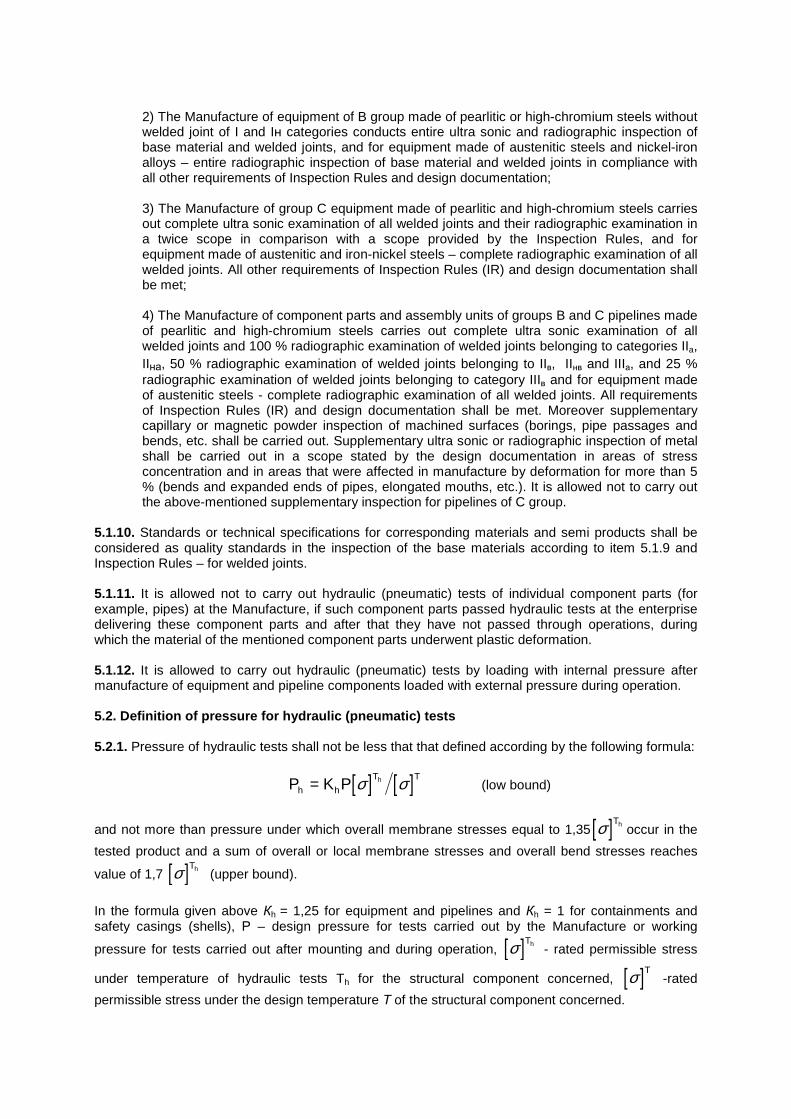
2) The Manufacture of equipment of B group made of pearlitic or high-chromium steels without welded joint of I and Iн categories conducts entire ultra sonic and radiographic inspection of base material and welded joints, and for equipment made of austenitic steels and nickel-iron alloys – entire radiographic inspection of base material and welded joints in compliance with all other requirements of Inspection Rules and design documentation; 3) The Manufacture of group C equipment made of pearlitic and high-chromium steels carries out complete ultra sonic examination of all welded joints and their radiographic examination in a twice scope in comparison with a scope provided by the Inspection Rules, and for equipment made of austenitic and iron-nickel steels – complete radiographic examination of all welded joints. All other requirements of Inspection Rules (IR) and design documentation shall be met; 4) The Manufacture of component parts and assembly units of groups B and C pipelines made of pearlitic and high-chromium steels carries out complete ultra sonic examination of all welded joints and 100 % radiographic examination of welded joints belonging to categories IIa, IIна, 50 % radiographic examination of welded joints belonging to IIв, IIнв and IIIа, and 25 % radiographic examination of welded joints belonging to category IIIв and for equipment made of austenitic steels - complete radiographic examination of all welded joints. All requirements of Inspection Rules (IR) and design documentation shall be met. Moreover supplementary capillary or magnetic powder inspection of machined surfaces (borings, pipe passages and bends, etc. shall be carried out. Supplementary ultra sonic or radiographic inspection of metal shall be carried out in a scope stated by the design documentation in areas of stress concentration and in areas that were affected in manufacture by deformation for more than 5 % (bends and expanded ends of pipes, elongated mouths, etc.). It is allowed not to carry out the above-mentioned supplementary inspection for pipelines of C group.
5.1.10. Standards or technical specifications for corresponding materials and semi products shall be considered as quality standards in the inspection of the base materials according to item 5.1.9 and Inspection Rules – for welded joints. 5.1.11. It is allowed not to carry out hydraulic (pneumatic) tests of individual component parts (for example, pipes) at the Manufacture, if such component parts passed hydraulic tests at the enterprise delivering these component parts and after that they have not passed through operations, during which the material of the mentioned component parts underwent plastic deformation. 5.1.12. It is allowed to carry out hydraulic (pneumatic) tests by loading with internal pressure after manufacture of equipment and pipeline components loaded with external pressure during operation. 5.2. Definition of pressure for hydraulic (pneumatic) tests 5.2.1. Pressure of hydraulic tests shall not be less that that defined according by the following formula:
[ ] [ ]P K Ph h
T Th= σ σ (low bound)
and not more than pressure under which overall membrane stresses equal to 1,35[ ]σ Th occur in the
tested product and a sum of overall or local membrane stresses and overall bend stresses reaches
value of 1,7 [ ]σ Th (upper bound).
In the formula given above Кh = 1,25 for equipment and pipelines and Кh = 1 for containments and safety casings (shells), Р – design pressure for tests carried out by the Manufacture or working
pressure for tests carried out after mounting and during operation, [ ]σ Th - rated permissible stress
under temperature of hydraulic tests Th for the structural component concerned, [ ]σ T -rated
permissible stress under the design temperature Т of the structural component concerned.
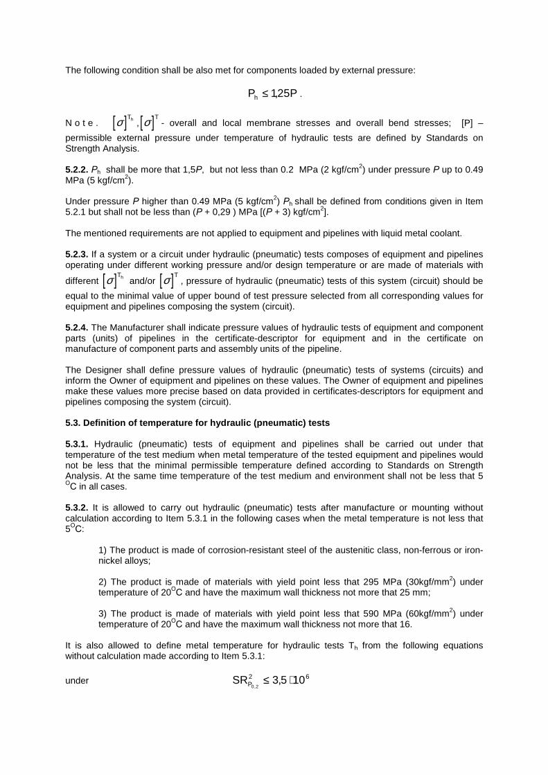
The following condition shall be also met for components loaded by external pressure:
P Ph ≤ 125, .
N o t e . [ ]σ Th ,[ ]σ T- overall and local membrane stresses and overall bend stresses; [P] –
permissible external pressure under temperature of hydraulic tests are defined by Standards on Strength Analysis. 5.2.2. Рh shall be more that 1,5Р, but not less than 0.2 MPa (2 kgf/cm2) under pressure Р up to 0.49 MPa (5 kgf/cm2). Under pressure Р higher than 0.49 MPa (5 kgf/cm2) Рh shall be defined from conditions given in Item 5.2.1 but shall not be less than (Р + 0,29 ) MPa [(Р + 3) kgf/cm2]. The mentioned requirements are not applied to equipment and pipelines with liquid metal coolant. 5.2.3. If a system or a circuit under hydraulic (pneumatic) tests composes of equipment and pipelines operating under different working pressure and/or design temperature or are made of materials with
different [ ]σ Th and/or [ ]σ T, pressure of hydraulic (pneumatic) tests of this system (circuit) should be
equal to the minimal value of upper bound of test pressure selected from all corresponding values for equipment and pipelines composing the system (circuit). 5.2.4. The Manufacturer shall indicate pressure values of hydraulic tests of equipment and component parts (units) of pipelines in the certificate-descriptor for equipment and in the certificate on manufacture of component parts and assembly units of the pipeline. The Designer shall define pressure values of hydraulic (pneumatic) tests of systems (circuits) and inform the Owner of equipment and pipelines on these values. The Owner of equipment and pipelines make these values more precise based on data provided in certificates-descriptors for equipment and pipelines composing the system (circuit). 5.3. Definition of temperature for hydraulic (pneum atic) tests 5.3.1. Hydraulic (pneumatic) tests of equipment and pipelines shall be carried out under that temperature of the test medium when metal temperature of the tested equipment and pipelines would not be less that the minimal permissible temperature defined according to Standards on Strength Analysis. At the same time temperature of the test medium and environment shall not be less that 5 ОС in all cases.
5.3.2. It is allowed to carry out hydraulic (pneumatic) tests after manufacture or mounting without calculation according to Item 5.3.1 in the following cases when the metal temperature is not less that 5ОС:
1) The product is made of corrosion-resistant steel of the austenitic class, non-ferrous or iron-nickel alloys; 2) The product is made of materials with yield point less that 295 MPa (30kgf/mm2) under temperature of 20ОС and have the maximum wall thickness not more that 25 mm; 3) The product is made of materials with yield point less that 590 MPa (60kgf/mm2) under temperature of 20ОС and have the maximum wall thickness not more that 16.
It is also allowed to define metal temperature for hydraulic tests Th from the following equations without calculation made according to Item 5.3.1:
under SRP0 2
2 63 5 10,
,≤ ⋅
T T SRh KO P≥ − + ⋅ −260 73 10 6 20 2,
;
under 3 5 106, ⋅ < SRP0 2
2 625 10,
≤ ⋅
T T SRh KO P≥ − + ⋅ −17 3 1 10 6 20 2
,,
;
under SRP0 2
2,
> 25 ⋅106
T T SRh KO P≥ + + ⋅ −48 0 47 10 6 20 2
,,
,
where TKO - critical temperature of material fragility at the initial state, ОС; S – maximum rated
thickness of the product wall, mm; RP0 2, - yield point of the material under temperature of 20ОС, MPa.
Value of TKO shall be either set by the design documentation and verified in the manufacture process or defined by techniques given in Standards on Strength Analysis. 5.3.3. The Designer shall define acceptable temperature of hydraulic tests carried out after manufacture according to Items 5.3.1 and 5.3.2 and indicate it on drawings, certificates-descriptors for equipment and certificates on manufacture of component parts and assembly units of pipelines. It is allowed to define the mentioned temperature using the actual properties of the metal used in manufacture. 5.3.4. The allowable metal temperature under hydraulic (pneumatic) tests of equipment and pipelines as parts of a system (circuit) after mounting is stated as the maximum temperature value from those indicated in certificates-descriptors for equipment (certificates on manufacture of component parts and assembly units of pipelines). The Owner indicates this value in the comprehensive program (manual) for hydraulic (pneumatic) tests. 5.3.5. The Owner of equipment sets a permissible metal temperature under hydraulic (pneumatic) tests carried out during operation (included those conducted after repair) based on the results of strength analysis, certificates-descriptors for equipment and pipelines, number of loading cycles fixed during operation, actual neutron fluence with energy Е ≥ 0,5 MeV, data on tests of templates installed to the nuclear reactor vessels. 5.3.6. In a case when the permissible metal temperature under hydraulic (pneumatic) tests is defined at the design stage based on the analysis according to Items 5.3.1 – 5.3.3 as a value that can not be provided by standard means of the NPI, the General Designer of the NPI shall provide a special device for ensuring the required temperature as a part of the NPI design. 5.4. Requirements for implementation of hydraulic ( pneumatic) tests 5.4.1. Equipment and pipelines shall be held under pressure of Ph during hydraulic tests for not less
that 10 min. After holding the pressure of hydraulic tests is brought down up to value of 0,8 Ph , and visual examination of equipment and pipelines is carried out in accessible places during time necessary for this examination. Minimal permissible metal temperature for holding shall be defined according to standards on strength analysis. Pressure during hydraulic tests shall be measured by two independent and tested pressure gages or measuring channels. Error of pressure measuring under hydraulic tests shall not exceed ± 5% of the rated value of test pressure with accounting of the grade of the sensor (pressure gage) accuracy. The grade of the sensor (pressure gage) accuracy shall not be less than 1.5.
5.4.2. It is allowed to set holding duration under pressure of Ph during tests after manufacture of accessories with inner diameter of connecting pipe branches not more than 100 mm according to technical documentation on the product. 5.4.3. Pressure fluctuations during hydraulic tests due to change of liquid temperature are allowed. The permissible values of temperature and pressure fluctuations shall be set by calculation or experiment individually for each specific case. At the same time the pressure value shall be within the low and upper bounds defined in Items 5.2.1 and 5.2.3. Decrease of temperature below the value defined in Item 5.3 is not allowed. It is allowed to compensate leaks of pump shaft seals anticipated by the design by pumping the test medium. 5.4.4. Hydraulic tests shall be carried out with the use of non-inflammable medium that does not have a harmful effect on equipment and pipelines. Requirements to quality of the test medium are set up by technical specifications for the product and shall be indicated in certificates-descriptors for equipment and pipelines or in certificates on manufacture of component parts and assembly units of pipelines. 5.4.5. Devices for temperature monitoring shall check metal temperature. It is allowed not to check temperature if liquid temperature and temperature of environment higher that temperature of hydraulic tests set up according to sub-section 5.3. Sensors and devices with total error less than ± 3% of the maximum value of the measured temperature shall be used to check temperature. 5.4.6. Measures to avoid accumulation of gas bubbles inside cavities filled with liquid shall be taken during hydraulic tests of equipment and pipelines. 5.5. Pneumatic tests 5.5.1. Pressure of pneumatic tests Pp shall not be less that that defined by the following formula:
[ ] [ ]P K Pp p
T Th= σ σ (low bound),
where Kp = 1,15 – for equipment and pipelines; Kp = 1 – for containments and safety casings (shells). The upper bound is the same as that defined in Item 5.2.1. The following condition shall be also met for components loaded by pressure:
Pp ≤ 1,25 [P]h . Requirements of Item 5.2.2 are not applied for pneumatic tests. 5.5.2. If liquid metal column exists in equipment and pipelines during their operation that unacceptable during pneumatic tests, then the low bound of pneumatic test pressure shall be defined according to the following formula:
[ ] [ ]P P Hp
T Th= +115, σ σ γ ,
where H – is a height of the liquid metal column; γ - is a specific mass of liquid metal under the design temperature; P – working pressure of gas above the level of liquid metal. 5.5.3. During pneumatic tests of safety casings (shells) equipment or pipelines covered by them can be under effect of external pressure. It can be necessary due to this fact to create backpressure Pg in equipment and pipelines. In this case the following condition shall be met:
Pp ≤ 1,15 [P] + Pg . 5.5.4. Directions of sub-section 5.3 shall be applied for determining minimum permissible temperature of the metal. 5.5.5. Requirements of items 5.2.3, 5.2.4, 5.3, 5.4.1 (with regard to requirements for the measuring accuracy and accuracy grade of devices) and items 5.4.3, 5.4.5 shall be met in pneumatic tests. 5.5.6. During pneumatic tests equipment and pipelines shall be held under pressure of Pp for at least 30 min. Pressure is brought down after holding and visual examination of equipment and pipelines is carried out in accessible places during time necessary for such an examination. Examination is carried out under pressure defined by a person responsible for tests based on safety conditions, but this pressure shall not exceed 0,85Pp for any cases. Technical specifications for delivery set up time of holding of accessories with inner diameter of connecting pipe branches not more that 100 mm under pressure during pneumatic tests. 5.5.7. Valves of the filling pipeline and devices for pressure and temperature measurements intended for pneumatic tests shall be installed in a place safe for personnel outside premises where the tested equipment is located. Personnel shall be in a safe place during gas pressure buildup in the tested equipment and pipelines, holding under pressure Pp and brought pressure down up to the value stated for the visual examination. 5.6. Programs of hydraulic (pneumatic) tests 5.6.1. The Manufacturer shall develop a production program (or process manual, process) of tests before implementation of hydraulic (pneumatic) tests of equipment and assembly units (component parts) of pipelines. 5.6.2. The Designer shall develop a comprehensive test program for implementation of hydraulic (pneumatic) tests. Based on this program the Owner of equipment and pipelines (or specialized organization designated by the Decision of the corresponding Ministry) shall develop a working test program for implementation of hydraulic (pneumatic) tests after mounting and during operation. 5.6.3. The production program (process manual, process) for hydraulic (pneumatic) tests of equipment and assembly units (component parts) of pipelines after their manufacture shall include the following data:
1) Name of equipment or assembly units (component parts) of pipelines; 2) Design pressure; 3) Pressure of hydraulic (pneumatic) tests; 4) Temperature of hydraulic (pneumatic) tests; 5) Test media and requirements for their quality; 6) Permitted rates of pressure buildup and bringing down; 7) Permitted rates of temperature buildup and bringing down; 8) Duration of holding under pressure of tests Ph (Pp); 9) Pressure, under which a visual examination shall be carried out; 10) Pressure source; 11) Method for test medium heating (if necessary);
12) Points of installation of pressure detectors (devices) and their accuracy grade; 13) Points of installation of temperature sensors (devices) and their accuracy grade; 14) Permissible limits of pressure and temperature fluctuations during holding; 15) Requirements for safety engineering (labor safety); 16) Places of installation of process plugs; 17) A list of administrative measures including nomination of persons responsible for tests.
The program shall be approved by the Chief Engineer (Manager) of the Manufacturer and coordinated with the corresponding design organization. 5.6.4. The comprehensive program for hydraulic (pneumatic) tests of systems, their parts or individual types of equipment and pipelines after mounting and during operation shall include the following data:
1) Name and boundaries of the tested system ( a part of the system, equipment, pipelines); 2) Working pressure; 3) Pressure of hydraulic (pneumatic) tests; 4) Temperature of hydraulic (pneumatic) tests; 5) Test media and requirements for their quality; 6) Permitted rates of pressure buildup and bringing down; 7) Permitted rates of temperature buildup and bringing down; 8) Pressure, under which a visual examination shall be carried out; 9) Methods of filling and drainage by the test medium; 10) Source of pressure; 11) Method for test medium heating (if necessary); 12) Points of installation of pressure detectors (devices) and their accuracy grade; 13) Points of installation of temperature sensors (devices) and their accuracy grade; 14) Permissible limits of pressure and temperature fluctuations during holding.
The comprehensive program shall be approved by the management of the Designer and coordinated with the Owner of equipment and pipelines. 5.6.5. The working program of hydraulic (pneumatic) tests shall contain the following data in addition to those listed in Item 5.6.4:
1) Verification of values of pressure and temperature of hydraulic (pneumatic) tests by certificates-descriptors for components of the tested equipment and pipelines; 2) Place of connection of the pressure source; 3) A list of the applied detectors and devices for pressure and temperature control with indication of their grade of accuracy;
4) Schedule of tests (stages of pressure buildup and relief, temperature increase and reduction, duration of holding, etc.); 5) Methods to inspect state of the tested equipment and pipelines in a course of visual inspection and after completion of the tests; 6) Measures on preparation for test implementation (with indication of closed and open valves limiting the tested system or its part); 7) A list of places where thermal insulation was taken off; 8) Measures against excess of pressure above the pressure value for tests; 9) Requirements for safety engineering (labor safety); 10) Administrative measures (including designation of a person responsible for tests); 11) A number of the comprehensive program used as a basis for development of the working program.
Management of the Owner of equipment and pipelines shall approve the working program. 5.6.6. Upon completion of the tests a report including the following data shall be developed:
1) Name of an enterprise carried out tests; 2) Name of the tested system (part of the system, equipment, pipelines, assembly units, component parts); 3) Design (working) pressure; 4) Design temperatures; 5) Pressure of tests; 6) Temperature of tests; 7) Test medium; 8) Duration of holding under pressure of tests; 9) Pressure of visual examination; 10) Number of working (production) program; 11) Results of tests;
12) Signature of the responsible person and date.
5.7. Assessment of the results of hydraulic (pneuma tic) tests Equipment and pipelines are considered as those passed hydraulic (pneumatic) tests, if leaks and metal raptures were not detected during tests and visual examination, pressure relief during the holding was within the limits specified by Item 5.4.3 and visible residual deformations were not revealed after tests. Leaks through process seals intended for tests are not a fault (defect) indicator, if they appear during hydraulic (pneumatic) tests of equipment and assembly units (components) of pipelines.
6. REQUIREMENTS FOR FITTING OUT OF EQUIPMENT AND PIPELINES WITH ACCESSORIES AND CONTROL AND MEASURING INSTRUMENTATION 6.1. General requirements 6.1.1. Number, type, place of installation and other requirements for accessories and control and measuring devices of equipment and pipelines are defined by the Designer based on the specific operational conditions and requirements of these Rules. 6.1.2. Backup of accessories and control and measuring devices shall be done according to requirements of General Safety Rules (OPB). 6.1.3. Installation of accessories and control and measuring devices shall provide a possibility for their maintenance, inspection, repair and replacement. 6.1.4. Accessories shall comply with requirements of OTT. 6.1.5. Closing of all types of driven accessories shall be done by hand wheel rotation clockwise and opening – counter clockwise. 6.1.6. Accessories shall have indicators of extreme positions of the flap and an indicator of its intermediate positions. Necessity of installation of the intermediate position indicator is defined by the design documentation. 6.1.7. The Manufacturer shall supply accessories together with a certificate-descriptor and operational manual. 6.1.8. Accessories requiring forcing of more than 296 N (30 kgf) for their opening and closing or remote controlled accessories shall be equipped with a mechanical drive. Use of bypass loops with relevant stop accessories on them is allowed for reduction of forces applied for opening. Use of accessories with manual drive is allowed with a force of moving out and finishing pressing out not more than 735 N (75 kgf), if such accessories are closed and opened not more that once per day. 6.1.9. Use of control accessories as stop ones and vice verse is not allowed. 6.1.10. A necessity to install stop accessories at the head and suction of pumps and an inverted valve placed between the pump and stop accessories is defined by the design documentation. Installation of stop accessories at the suction of pumps connected to tanks working under atmospheric pressure is not required. 6.1.11. Pipeline sections and equipment that can be examined or repaired during operation, as well as low pressure pipelines that are connected to lines with pressure of 2.2 MPa (22 kgf/cm2) or higher shall be cut off by two consecutive stop devices with drainage between them. Pipelines of safety systems connected to the primary circuit, circuit of multiple forced circulation shall be isolated from it by two consecutively installed check valves and one stop device. Drainage with throughout capacity exceeding design leakage of the check valve in more than ten times shall be installed between the isolating device and the first check valve with regard to the media flow. During in-service repair work when the unit is at the power level isolating devices shall be closed, drainage line valves shall be open, electric power supply circuits shall be disassembled, power supply cabinets shall be locked and sealed up, records in the operational log books shall be made. Isolating devices can be in an open state when the unit is at the power level and safety systems are at the duty state. Drain valves shall be open and isolating devices closed during disconnection. Movement of the moving parts of the devices shall be impossible due to mechanical method applied. Control circuits shall be disassembled and handweels shall be either taken off or locked.
Requirement for installation of the drain valves between isolating devices at the border between high and low pressure is not applied for the impulse lines of instrumentation and control (I&C). Design shall provide engineering and administrative measures that avoid a possibility to change a state of the mentioned devices due to error actions of the personnel. Pipeline sector and equipment connected to lines with higher pressure of up to 2.2 MPa (2,2 kgf/cm2) that are examined or repaired during operation can be cut off by one isolating device. During in-service examination or repair devices shall be closed and movement of their moving parts shall be eliminated mechanically (except of devices located inside containment). Handweels shall be taken off or locked, electric power supply circuits shall de disassembled, power supply cabinets shall be locked and sealed up, records in the operational log books shall be made. 6.1.12. Accessories of Groups A and B equipment and pipelines, the unauthorized movement of stop valves of those can result in consequences affecting NPI safety, shall have locking devices and devices for indication of the stop device position. Design documentation defines a necessity to install locking devices and indicating devices. 6.2. Safety devices 6.2.1 Safety devices shall be installed on equipment and pipeline where pressure can exceed the value of working pressure due to both chemical and physical processes taking place in them and external sources of pressure increase estimated with accounting of conditions presented in Item 2.1.7 If pressure in equipment and pipelines cannot exceed working pressure installation of safety devices is not required. This shall be justified by the design in compliance with requirements of OPB-88. Equipment of the primary circuit and safety casing shall be designed for loads occurred in case of reactor vessel integrity failure and coolant leakage to the safety casing. All sections of equipment and pipelines with single-phase medium (water, liquid metal) cut off from two sides and that can be heated by any method shall be equipped with safety devices. 6.2.2. Number of safety devices, their throughput capacity and settings for opening (closure) shall be defined by the Designer so that pressure in the protected equipment and pipelines does not exceed value of 15 % more than working pressure in actuation of these devices (taking into account dynamic of transients in equipment and pipelines and dynamic and time of safety device actuation) and does not result in inadmissible dynamic impacts on safety devices. It is allowed to consider an advanced actuation of NPI emergency protection in the analysis of pressure increase dynamics in the protected equipment and pipelines. For systems with possible short-term local pressure increase (for example, in case of chemical effect of liquid metal coolant and water) the local pressure increase under which safety devices shall be actuated is allowed (taking into account hydraulic resistance along the section from the place of pressure increase up to safety devices). Such a possibility shall be provided by the design and justified by strength analysis. 6.2.3. Pressure increase for not more than 0.05 MPa is allowed in equipment and pipelines with working pressure of up to 0.3 MPa. A possibility to increase pressure by the mentioned value shall be justified by strength analysis of the corresponding equipment and pipelines. 6.2.4. If a safety device protects a number of equipment items connected to each other it shall be selected and set up based on the lowest working pressure for each of those equipment items. 6.2.5 Design of safety devices shall ensure their closure after actuation in case of pressure reaching value not less than 0.9 of working pressure used for selection of setting for actuation of these safety devices.
The mentioned requirement is not applied for safety membranes and hydraulic seals. 6.2.6. The Designer shall specify a setting for fit of impulse safety devices with mechanized (electromagnetic or other) drive based on the specific operational conditions of equipment and pipelines. 6.2.7. Number of safety devices and/or safety membranes with forced rupture installed to protect equipment and pipelines of A and B groups shall be higher than the number defined according to item 6.2.2 by not less than one. The mentioned requirement is not applied to membranes of direct rupture and hydraulic seals. 6.2.8. Throughput capacity of safety devices shall be estimated in compliance with GOST 12.2.085-82. Throughput capacity of safety devices shall be checked in the corresponding tests of this design prototype carried out by the Manufacturer of safety devices. 6.2.9. Total effect of all possible sources of pressure with consideration of analysis of design basis accidents able to result in pressure increase shall be taken into account for selection of number and throughput capacity of safety devices. 6.2.10. Safety valve that makes impossible pressure increase in pipelines higher than value of working pressure shall be installed on pressure pipelines between a plunger pump that does not have safety valve and a stop valve. 6.2.11. It is not allowed to install stop devices between safety device (membrane or other safety device according to item 2.1.7) and equipment and pipelines protected by it, as well as on lateral and drain pipelines. It is allowed to install stop devices before impulse valves of impulse safety devices (ISD) and after them if ISD are equipped with not less than two impulse valves and mechanical interlock of the mentioned stop devices allows failure of only one of these valves. 6.2.12. Use of impulse valves with the lever drive is not allowed. 6.2.13. Internal diameter of safety devices and impulse valve shall not be less than 15 mm. 6.2.14. Change in setting for spring and other alignment elements in safety devices shall be impossible. Springs of spring safety valves and impulse valves of ISD shall be protected against direct impact of media and overheating. 6.2.15. It is allowed to install switching devices before safety devices if double number of impulse safety devices or safety valves is available and protection of equipment and pipelines against pressure increase is ensured in case of any position of switching devices. 6.2.16. Safety device design shall provide a possibility to check correctness of its performance by its opening manually or from the control panel. For impulse safety devices this requirements is applied to the impulse valve. Force of manual opening shall not exceed 196 N (20 kgf). If it is impossible to check performance of safety devices during operation of equipment, switching devices installed before them and allowing examination of each safety device with their disconnection from the equipment shall be used. Switching devices shall be such as to provide connection of the required number of safety devices (necessary to ensure compliance with requirements of item 6.2.2) with equipment and pipelines under any state of those switching devices. Requirements specified in this Item are not applied to membranes and hydraulic seals.
6.2.17. Safety valves (impulse channels for ISD) protecting equipment and pipelines of A and B groups shall have mechanized (electromagnetic and other) drives providing timely opening and closure of the mentioned valves in accordance with requirements of item 6.2.2 or 6.2.3 and 6.2.5. These valves shall be designed and adjusted in such a way that to act as direct-acting valves in case of drive failure and to provide compliance with the items mentioned above. If a few valves are available at the protected object mechanized drives of these valves shall have control and power supply channels independent of each other. Mechanized drives can be used to check operability and for forced pressure suppression in the protected object. The Designer shall define if installation of valves with such a drive is necessary for equipment of C group. 6.2.18. Safety devices shall be installed on branches and pipelines directly attached to equipment. It is allowed to install safety devices on branches attached to pipelines. If a few safety devices are installed on one collector (pipeline), cross-section area of the collector (pipeline) shall not be less than 1.25 of the design total cross-section area of conjunctive branches of safety devices installed on it. Pressure impulse for safety device opening shall be taken from the protected equipment. It is allowed to take impulse from the pipeline where safety devices are installed taking into account hydraulic resistance of the pipeline. 6.2.19. Installation of membrane safety devices burst in case of pressure increase in the protected equipment by 25 % of the medium working pressure is allowed for equipment and pipelines with liquid metal coolant and of C group (if their burst is verified by calculation). Installation of membrane safety devices before the safety valve is allowed if a device providing control of operability of the bursting membrane and eliminating a possibility of getting of ruptured bursting membrane parts to the safety valve would be installed between them. Operability of a composition of bursting safety device and safety valve shall be verified by testing. Flow area of a device with the ruptures membrane shall not be less than flow area of the inlet branch of safety devices. The membrane marking shall be visible after its installation. 6.2.20. Flow coefficient and size of the minimal orifice flow of the seat shall be indicated in the certificate-descriptor on safety devices for the completely opened valve. Requirements for presenting these data in the certificate-descriptor are not applied to impulse safety valves. 6.2.21. Equipment working under pressure that is less than the source pressure shall have automatic reducer (governor of pressure after itself) installed on the supply pipeline with pressure gage and safety devices installed on the side of lower pressure. Installation of a single automatic reducer with pressure gage and safety devices installed on one main line before the first branching is allowed for the whole group of equipment working under the same pressure and from the same supply source. In cases when it is not possible due to process reasons or not required to maintain constant pressure after the reducer the unregulated reducing devices (washers, throttles, etc.) can be installed on pipelines coming from the supply source. On pipelines connecting regenerative heaters of turbine installation by the condensate of heating steam valves regulating condensate level in apparatus casings can function as reducers. 6.2.22. If a pipeline along the section from automatic reducer up to equipment is designed to sustain the maximum pressure of the supply source and a safety device is installed on the equipment, installation of a safety device on the pipeline after the reducer is not required. 6.2.23. If the design pressure of equipment is equal to or more than pressure of the supplying source and there is no a possibility to increase pressure in the equipment due to external and internal power sources, installation of safety devices is not necessary. 6.2.24. Automatic governors and safety devices are not required on:
1) Pump recirculation pipelines;
2) Pipelines after level controllers; 3) Pipelines for blowing, draining and air removal during medium discharge to equipment equipped with safety devices in compliance with item 6.2.9.
Need to install throttle washers on these pipelines is specified by the design documentation. 6.2.25. Safety devices of equipment and pipelines shall be installed at places accessible for maintenance and repair. 6.2.26. Outlet pipes without self-draining shall be equipped with drainage device. It is not allowed to install stop devices on the drainpipes. Internal diameter of the outlet pipes shall not be less than diameter of the outlet branch of the safety valve and shall be designed so as under the maximum flow rate the back pressure near the outlet branch does not exceed the maximum value of back pressure specified for this valve. Working medium coming from safety devices shall be taken off to a place safe for the personnel. 6.2.27. Examination of operability of safety devices including control circuits with release of the working medium shall be carried out before the first start up of equipment with working parameters and before the further scheduled start ups but not less than once per twelve months. If defects or failures of device or control circuit actuation are revealed repair work should be done with following additional examination. 6.2.28. Alignment of safety devices should be examined after mounting, after repair of devices or control circuits affecting alignment but not less than once per twelve months. Such examination is carried out by pressure buildup in the equipment using arrangements being a part of the delivery set of these devices or by testing at the stationary test bench. After alignment of safety devices for actuation the alignment unit shall be sealed. Data on alignment shall be registered in the logbook of operation and repair of safety devices. 6.2.29. Examination of operability and alignment of systems protecting equipment and pipelines against pressure or temperature excess (Item 2.1.7) shall be carried out in terms specified in Items 6.2.2 and 6.2.28. 6.2.30. Check of operability of hydraulic seals, replacement of safety membranes and examination of forced burst devices shall be carried out according to a schedule approved by the Chief Engineer of the NPI. 6.3. Equipping with control and measuring devices 6.3.1. Equipment and pipelines shall be equipped with control and measuring instrumentation to measure pressure, temperature, flow rate and level of working medium, chemical composition of coolant and gas, as well as to control movements and confinement Integrity). 6.3.2. At least three independent level indicators shall be installed on steam generators, pressurizers, drum-type steam separators and sound and light alarms for the upper and low levels shall be provided. 6.3.3. Devices for recording of changes of temperature of coolant and/or wall metal shall be provided for reactors, steam generators, drum-type steam separators, main steam pipelines and other equipment and pipelines working under temperature higher than 150ОС, for which the design documentation specifies the temperature change rate. Points of temperature monitoring shall be indicated in the design documentation. 6.3.4. For vessels of fast breeder reactors, steam generators, drum-type steam separators and pipelines of systems of B and C groups with outer diameter more than 300 mm working under temperature higher than 250оС devices providing for periodical control of movement of the mentioned equipment and pipelines and recording of maximal values of movement shall be installed. If equipment
and pipelines are located inside the unattended premises, the remote control and recording of movements shall be arranged. 6.3.5. Layout of installation of the control and measuring devices shall provide for a possibility for periodical examination of correctness of their functioning in the laboratory and/or in the place of their installation. Operational manuals for equipment and pipelines shall specify an order and terms of examination. 6.3.6. The Designer shall define a scope of control according to Items 6.3.1 – 6.3.4, places of installation of detectors and sampling devices, methods of control, accuracy and limits of safe operation. These data shall be presented in the design documentation. 6.3.7. Prime detectors and sampling devices being in contact with liquid metal coolant shall be installed so as a place of detector embedding would not be the coldest point of the circuit (with a purpose to avoid deposition of impurities contained in liquid metal coolant). Pipe heating up to the circuit temperature shall be provided if the length of communication lines containing liquid metal from the detector location to the place of connection to the circuit exceeds five rated outer diameters of pipes of these communication lines. 6.3.8. Prime detectors permanently working at the bound between liquid metal and gas (for example, level indicator) shall be resistant against slagging of their surfaces by impurities existing on the free surface of liquid metal. 6.3.9. Accuracy grade of control and measuring devices used for monitoring of equipment and pipeline parameters shall not be lower than 1.5. The required accuracy of measurements of control parameters shall be indicated in the design documentation. At the same time error of temperature measuring shall not exceed 2%. 7. IN-SERVICE INSPECTION OF METAL OF EQUIPMENT AND PIPELINES. GENERAL REQUIREMENTS 7.1. General requirements 7.1.1. Equipment and pipelines of groups A and B shall be periodically examined by the NPI personal in a scope set up by these Rules and technical documentation that regulates a specific procedure on inspection implementation at the NPI. The Designer defines a necessity and a scope of inspection of group C equipment and pipelines. 7.1.2. The objective of the in-service metal inspection of equipment and pipelines is the following:
1) Detection and recording of metal flaws; 2) Detection and recording of changes in physical-chemical properties and structure of metal; 3) Assessment of metal state.
7.1.3. Metal inspection is subdivided into prior commissioning, periodical and extra inspection. 7.1.4. Prior commissioning inspection is carried out before commissioning of the NPI. 7.1.5. Periodical inspection is carried out according the planned schedule during operation of the NPI. 7.1.6. Extra inspection is carried out:
1) After earthquake that id equal to or more severe than the design earthquake; 2) In case of violation of normal operational conditions or in case of emergencies that resulted to changes in performance indicators of equipment and pipelines up to the level exceeding the design level;
3) Upon decision of the Management of the Owner of equipment and pipelines or the local office of Gosatomenergonadzor of the USSR.
7.2. Units under inspection 7.2.1. Organizations of ministries (agencies) under which authority the NPI is develop the standard inspection programs that define a specific list of equipment and pipelines subject to inspection. Standard programs shall be coordinated with the General Designer of the NPI, General Designer of the reactor installation and Gosatomenergonadzor of the USSR. 7.2.2. The following is subject to the obligatory inspection:
1) Equipment of group A (vessels of VVER reactors, NHI) – welded joints and anticorrosion claddings, base material in areas of stress concentration and in areas opposite the reactor core, welded joints and radius passages of joining branches of pipelines, sealing surfaces of detachable joints of vessels and heads, welded joints for attaching of supports, studs, metal in the threaded holes for studs and support ledges of press-on rings; 2) Equipment of group A (fast breeder reactor vessels) – welds for welding of safety casings to the main vessel, as well as all welds of reactor vessel and welds for welding of other components to it in the area of absence of the safety casing; 3) Equipment of group A [except of that mentioned in 1) and 2)], equipment of group B – all welded joints of casings and base material in stress concentration arrears, weld for welding of branches to the casing and head, welded joints of headers or tube plates of the steam generators, inner surface of casings in the steam-water area, radius passages of branches, areas of bridges between apertures in the casing, welds for support welding, bolts and studs, metal in the threaded holes for bolts and studs; 4) Pipelines of group B – welded joints and anticorrosion claddings of pipes and headers, bends, welds for welding of branches and pipes in the areas of bending, welds of T-shape joints, passages, attachment of supports (on pipelines of the NPI systems with fast breeder reactors the mentioned inspection shall be carried out in places where is an absence of safety shells and in the areas of these shells welding to the pipelines); 5) Safety casings of NHI – areas of pipeline penetrations.
7.2.3. It is allowed to carry out inspection in the individual sections of the mentioned above areas of equipment and pipelines that are indicated in the working inspection programs. 7.3. Inspection methods (techniques) 7.3.1. Metal state is inspected during operation by non-destructive and destructive methods. 7.3.2. The following techniques are applied for non-destructive metal inspection:
1) Visual examination; 2) Capillary or magnetic powder inspection; 3) Ultra sonic inspection; 4) Radiographic inspection; 5) Other inspection techniques that provide detection of metal flaws specified by the standard inspection program in case of availability of process procedures and rules for their application approved according to the established procedure.
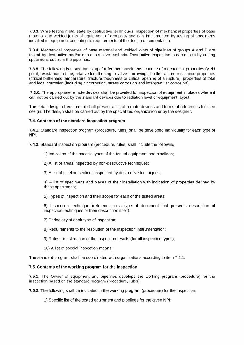
7.3.3. While testing metal state by destructive techniques, Inspection of mechanical properties of base material and welded joints of equipment of groups A and B is implemented by testing of specimens installed in equipment according to requirements of the design documentation. 7.3.4. Mechanical properties of base material and welded joints of pipelines of groups A and B are tested by destructive and/or non-destructive methods. Destructive inspection is carried out by cutting specimens out from the pipelines. 7.3.5. The following is tested by using of reference specimens: change of mechanical properties (yield point, resistance to time, relative lengthening, relative narrowing), brittle fracture resistance properties (critical brittleness temperature, fracture toughness or critical opening of a rupture), properties of total and local corrosion (including pit corrosion, stress corrosion and intergranular corrosion). 7.3.6. The appropriate remote devices shall be provided for inspection of equipment in places where it can not be carried out by the standard devices due to radiation level or equipment layout. The detail design of equipment shall present a list of remote devices and terms of references for their design. The design shall be carried out by the specialized organization or by the designer. 7.4. Contents of the standard inspection program 7.4.1. Standard inspection program (procedure, rules) shall be developed individually for each type of NPI. 7.4.2. Standard inspection program (procedure, rules) shall include the following:
1) Indication of the specific types of the tested equipment and pipelines; 2) A list of areas inspected by non-destructive techniques; 3) A list of pipeline sections inspected by destructive techniques; 4) A list of specimens and places of their installation with indication of properties defined by these specimens; 5) Types of inspection and their scope for each of the tested areas; 6) Inspection technique (reference to a type of document that presents description of inspection techniques or their description itself); 7) Periodicity of each type of inspection; 8) Requirements to the resolution of the inspection instrumentation; 9) Rates for estimation of the inspection results (for all inspection types); 10) A list of special inspection means.
The standard program shall be coordinated with organizations according to item 7.2.1. 7.5. Contents of the working program for the inspec tion 7.5.1. The Owner of equipment and pipelines develops the working program (procedure) for the inspection based on the standard program (procedure, rules). 7.5.2. The following shall be indicated in the working program (procedure) for the inspection:
1) Specific list of the tested equipment and pipelines for the given NPI;
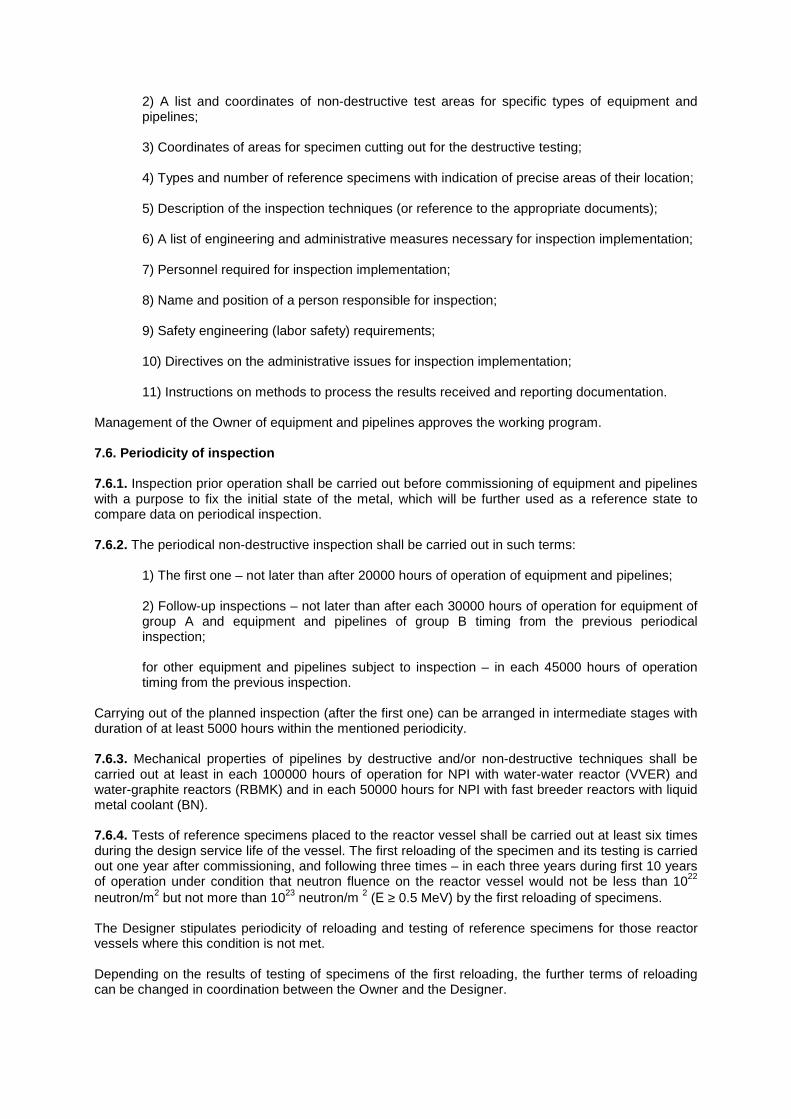
2) A list and coordinates of non-destructive test areas for specific types of equipment and pipelines; 3) Coordinates of areas for specimen cutting out for the destructive testing; 4) Types and number of reference specimens with indication of precise areas of their location; 5) Description of the inspection techniques (or reference to the appropriate documents); 6) A list of engineering and administrative measures necessary for inspection implementation; 7) Personnel required for inspection implementation; 8) Name and position of a person responsible for inspection; 9) Safety engineering (labor safety) requirements; 10) Directives on the administrative issues for inspection implementation; 11) Instructions on methods to process the results received and reporting documentation.
Management of the Owner of equipment and pipelines approves the working program. 7.6. Periodicity of inspection 7.6.1. Inspection prior operation shall be carried out before commissioning of equipment and pipelines with a purpose to fix the initial state of the metal, which will be further used as a reference state to compare data on periodical inspection. 7.6.2. The periodical non-destructive inspection shall be carried out in such terms:
1) The first one – not later than after 20000 hours of operation of equipment and pipelines; 2) Follow-up inspections – not later than after each 30000 hours of operation for equipment of group A and equipment and pipelines of group B timing from the previous periodical inspection; for other equipment and pipelines subject to inspection – in each 45000 hours of operation timing from the previous inspection.
Carrying out of the planned inspection (after the first one) can be arranged in intermediate stages with duration of at least 5000 hours within the mentioned periodicity. 7.6.3. Mechanical properties of pipelines by destructive and/or non-destructive techniques shall be carried out at least in each 100000 hours of operation for NPI with water-water reactor (VVER) and water-graphite reactors (RBMK) and in each 50000 hours for NPI with fast breeder reactors with liquid metal coolant (BN). 7.6.4. Tests of reference specimens placed to the reactor vessel shall be carried out at least six times during the design service life of the vessel. The first reloading of the specimen and its testing is carried out one year after commissioning, and following three times – in each three years during first 10 years of operation under condition that neutron fluence on the reactor vessel would not be less than 1022 neutron/m2 but not more than 1023 neutron/m 2 (Е ≥ 0.5 MeV) by the first reloading of specimens. The Designer stipulates periodicity of reloading and testing of reference specimens for those reactor vessels where this condition is not met. Depending on the results of testing of specimens of the first reloading, the further terms of reloading can be changed in coordination between the Owner and the Designer.
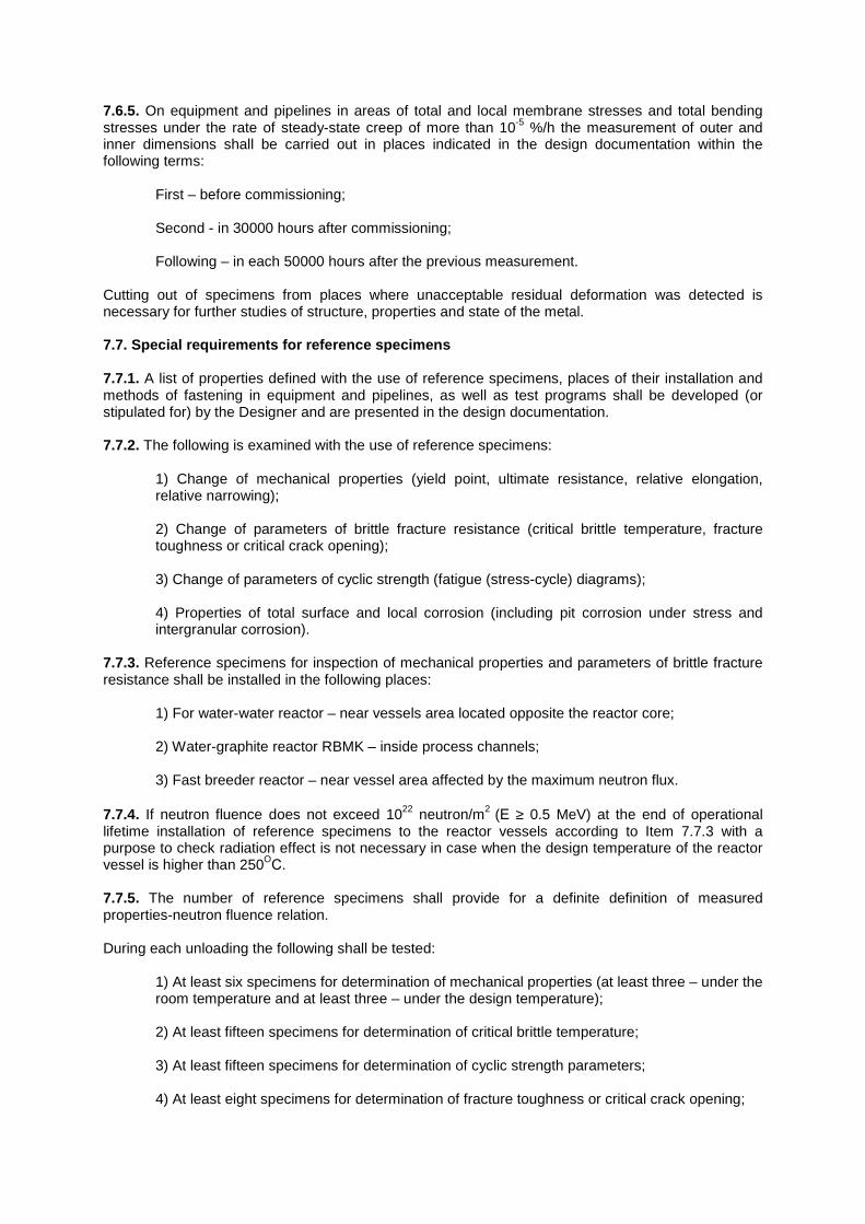
7.6.5. On equipment and pipelines in areas of total and local membrane stresses and total bending stresses under the rate of steady-state creep of more than 10-5 %/h the measurement of outer and inner dimensions shall be carried out in places indicated in the design documentation within the following terms:
First – before commissioning; Second - in 30000 hours after commissioning; Following – in each 50000 hours after the previous measurement.
Cutting out of specimens from places where unacceptable residual deformation was detected is necessary for further studies of structure, properties and state of the metal. 7.7. Special requirements for reference specimens 7.7.1. A list of properties defined with the use of reference specimens, places of their installation and methods of fastening in equipment and pipelines, as well as test programs shall be developed (or stipulated for) by the Designer and are presented in the design documentation. 7.7.2. The following is examined with the use of reference specimens:
1) Change of mechanical properties (yield point, ultimate resistance, relative elongation, relative narrowing); 2) Change of parameters of brittle fracture resistance (critical brittle temperature, fracture toughness or critical crack opening); 3) Change of parameters of cyclic strength (fatigue (stress-cycle) diagrams); 4) Properties of total surface and local corrosion (including pit corrosion under stress and intergranular corrosion).
7.7.3. Reference specimens for inspection of mechanical properties and parameters of brittle fracture resistance shall be installed in the following places:
1) For water-water reactor – near vessels area located opposite the reactor core; 2) Water-graphite reactor RBMK – inside process channels; 3) Fast breeder reactor – near vessel area affected by the maximum neutron flux.
7.7.4. If neutron fluence does not exceed 1022 neutron/m2 (Е ≥ 0.5 MeV) at the end of operational lifetime installation of reference specimens to the reactor vessels according to Item 7.7.3 with a purpose to check radiation effect is not necessary in case when the design temperature of the reactor vessel is higher than 250O
С. 7.7.5. The number of reference specimens shall provide for a definite definition of measured properties-neutron fluence relation. During each unloading the following shall be tested:
1) At least six specimens for determination of mechanical properties (at least three – under the room temperature and at least three – under the design temperature); 2) At least fifteen specimens for determination of critical brittle temperature; 3) At least fifteen specimens for determination of cyclic strength parameters; 4) At least eight specimens for determination of fracture toughness or critical crack opening;
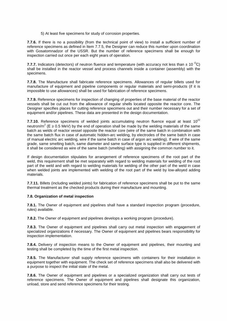
5) At least five specimens for study of corrosion properties.
7.7.6. If there is no a possibility (from the technical point of view) to install a sufficient number of reference specimens as defined in Item 7.7.5, the Designer can reduce this number upon coordination with Gosatomnadzor of the USSR. But the number of reference specimens shall be enough for inspection carried out once per each eight years of operation. 7.7.7. Indicators (detectors) of neutron fluence and temperature (with accuracy not less than ± 10 ОС) shall be installed in the reactor vessel and process channels inside a container (assembly) with the specimens. 7.7.8. The Manufacture shall fabricate reference specimens. Allowances of regular billets used for manufacture of equipment and pipeline components or regular materials and semi-products (if it is impossible to use allowances) shall be used for fabrication of reference specimens. 7.7.9. Reference specimens for inspection of changing of properties of the base material of the reactor vessels shall be cut out from the allowance of regular shells located opposite the reactor core. The Designer specifies places for cutting reference specimens out and their number necessary for a set of equipment and/or pipelines. These data are presented in the design documentation. 7.7.10. Reference specimens of welded joints accumulating neutron fluence equal at least 1022
neutron/m2 (Е ≥ 0.5 MeV) by the end of operation shall be made by the welding materials of the same batch as welds of reactor vessel opposite the reactor core (wire of the same batch in combination with the same batch flux in case of automatic hidden-arc welding, by electrodes of the same batch in case of manual electric arc welding, wire if the same batch in case of argon arc welding). If wire of the same grade, same smelting batch, same diameter and same surface type is supplied in different shipments, it shall be considered as wire of the same batch (smelting) with assigning the common number to it. If design documentation stipulates for arrangement of reference specimens of the root part of the weld, this requirement shall be met separately with regard to welding materials for welding of the root part of the weld and with regard to welding materials for welding of the other part of the weld in case when welded joints are implemented with welding of the root part of the weld by low-alloyed adding materials. 7.7.11. Billets (including welded joints) for fabrication of reference specimens shall be put to the same thermal treatment as the checked products during their manufacture and mounting. 7.8. Organization of metal inspection 7.8.1. The Owner of equipment and pipelines shall have a standard inspection program (procedure, rules) available. 7.8.2. The Owner of equipment and pipelines develops a working program (procedure). 7.8.3. The Owner of equipment and pipelines shall carry out metal inspection with engagement of specialized organizations if necessary. The Owner of equipment and pipelines bears responsibility for inspection implementation. 7.8.4. Delivery of inspection means to the Owner of equipment and pipelines, their mounting and testing shall be completed by the time of the first metal inspection. 7.8.5. The Manufacturer shall supply reference specimens with containers for their installation in equipment together with equipment. The check set of reference specimens shall also be delivered with a purpose to inspect the initial state of the metal. 7.8.6. The Owner of equipment and pipelines or a specialized organization shall carry out tests of reference specimens. The Owner of equipment and pipelines shall designate this organization, unload, store and send reference specimens for their testing.
7.8.7. Inspection results shall be registered in a protocol or report that are reporting documentation on inspection. 7.8.8. The following data shall be presented in the reporting documentation on the non-destructive inspection:
1) Number of the standard inspection program (procedure, rules); 2) Number of the working inspection grogram (procedure); 3) Inspected areas, inspection methods used; 4) Description of techniques for inspection including used instrumentation, sensitivity and other main parameters; 5) Inspection results (in case of detecting of unacceptable inspection index it is necessary to indicate a type, precise location and value of the index); 6) Fixed deviations from the working program (procedure); 7) Comparison of the scope of the implemented inspection with that required by the standard program; 8) Assessment of the inspection results; 9) Signature of a person responsible for implementation of the inspection.
7.8.9. The following data shall be presented in the reporting documentation on the testing of specimens:
1) Number of the standard inspection program (procedure, rules); 2) Number of the working inspection grogram (procedure); 3) Areas of cutting specimens out from the pipelines or areas of reference specimens’ installation; 4) Materials of specimens, their initial properties; 5) Description of areas of specimens’ location (type of coolant, working pressure, temperature of specimens, neutron flux and fluence, duration of operation); 6) Types of tests and techniques of their implementation; 7) Results obtained; 8) Assessment of the inspection results; 9) Signature of a person responsible for implementation of the inspection.
7.8.10. The Management of the Owner of equipment and pipelines shall approve protocols or reports mentioned in Item 7.8.7. A record is inserted to the certificates-descriptors of vessels and pipelines after any inspection. 7.8.11. If results of inspection are unacceptable the reporting documents on the implemented inspection and suggested solutions are submitted to the ministry (agency) that controls the Owner of equipment and pipelines and Gosatomenergonadzor of the USSR. They take decision on the results of inspection with involvement of the Designer, Manufacturer (mounting organization) and leading metal science organization (if necessary).
7.8.12. The Owner of equipment and pipelines shall store documentation on metal inspection during the whole period of their service life. 8. REGISTRATION AND TECHNICAL EXAMINATION 8.1. Registration of equipment and pipelines 8.1.1. Equipment and pipelines subject to compliance with these Rules shall be registered in the local offices of Gosatomenergonadzor of the USSR and taken for accounting by the Owner of equipment and pipelines after completion of their mounting and before implementation of technical examination. 8.1.2. The following equipment and pipelines are subject to registration at the local offices of Gosatomenergonadzor of the USSR:
1. Equipment and pipelines of group A.
2. Equipment of group B.
3. Equipment of group C under any of the following conditions:
• If damage of equipment results in release of medium and high level radioactive media (according to definition given in “Health (sanitary) Rules for Design and Operation of Nuclear Power Plants”);
• Coolant temperature is higher than 200 ОС; • Coolant temperature does not exceed 200 ОС, but product of volume, m3(l), and
working pressure, MPa (kgf/cm2), exceeds 1(10 000 l ⋅ kgf/cm 2).
4. Pipelines of group B with outer diameter equal to or more than 57 mm. 5. Pipelines of group C:
• With outer diameter of 57 mm and higher that contain medium and high level
radioactive coolant; • Other pipelines with outer diameter of 108 mm and higher;
6. Casings of main circulation pumps.
8.1.3. Equipment and pipelines that are not listed in Item 8.1.2 are subject to registration at the Owner by engineer of this enterprise that was appointed by the Order to supervise over the equipment and pipelines (supervisor). 8.1.4. Specific nomenclature of equipment to be registered at the local offices of Gosatomenergonadzor of the USSR, bounds of equipment and pipeline registration are defined by the lists developed by the General Designer together with the NPI Management and Chief Engineering organization. The nomenclature and bounds of equipment and pipeline registration shall be coordinated with Gosatomenergonadzor of the USSR. The mentioned lists shall be developed by the start of mounting activities. N o t e : Equipment mentioned in paragraphs 1,2,3 of Item 8.1.2 comprise of components of reactors and vessels working under pressure, as well as safety casings of fast breeder reactors and reactors of NHI. 8.1.5. The following requirements shall be taken into consideration in determining of registration bounds of equipment and pipelines:
• Inlet (outlet) branches and nozzles are registration bounds of the vessel (welded joint of welding pipeline to the vessel nozzle belongs to the pipeline). Only some short sections of
pipelines (for example, those for attaching safety devices) are allowed to be registered together with the vessel;
• It is allowed to register separately reactor components (vessel, heads, cases of control rod
drives, process channels, etc.), tanks and heads of deaerator, etc., if a certificate-descriptor for these products are available;
• If at least one cavity of equipment shall be registered due to medium parameters or belonging
to specific groups, such equipment shall be registered as a whole as equipment belonging to the highest group;
• Accessories (valves) shall be registered as parts of the pipelines; • If accessories are installed at the vessel branch, they are registered as part of the equipment;
• Sections of low-pressure pipelines after reactor installation, fast-acting exhaust stations,
reduction and cooling plant, fact-acting reduction and cooling plant, etc. together with safety devices and the first stop device along the medium flow are registered jointly with low-pressure pipelines;
• Discharge pipelined from safety devices and reducers are not registered if medium is
discharged to the tank being under atmospheric pressure or vacuum; • Inlet and outlet branches are bounds of the pump; • Main pipelines are registered up to the weld of their welding to the branch of casing of the
turbine isolation valve; • If there is no a stop device on the section of the steam bleeding pipeline from the turbine up to
the vessel, the check valve serves as a bound of the pipeline section that is not cut off. If the stop valve is unavailable the weld for welding pipeline to the vessel serves as that bound.
8.1.6. All equipment and pipelines subject to compliance with these Rules shall be accounted at the Owner of equipment and pipelines in a log book for accounting and examination by an engineer of this enterprise designated by the Order as a person responsible for supervision over equipment and pipelines (supervisor). 8.1.7. The following documents shall be submitted with a purpose to register equipment at the local office of Gosatomenergonadzor of the USSR:
1. Application of the Owner Management in written.
2. Equipment certificate-descriptor of the established format with the corresponding enclosure.
3. Connection diagram for equipment with indication of working medium parameters,
pressure sources and their parameters (maximum value of the produced pressure and flow rate), accessories, safety and control and measuring devices, bleeding, blowing and draining devices.
4. Report confirming that mounting and installation of equipment were carried out in
compliance with the design and requirements of these Rules, and equipment is in the operable condition. The Chief Engineer or Manager of the mounting organization and the Owner of equipment and pipelines shall approve this report. A drawing where actual data on installation of equipment and data on installation of supports, movement limiters and shock absorbers are indicated shall be enclosed to the report.
8.1.8. The following documents shall be submitted with a purpose to register pipelines at the local offices of Gosatomenergonadzor of the USSR:
1. Application of the Owner Management in written. 2. Pipeline certificate-descriptor of the established format with the corresponding enclosure.
3. Space diagram of pipelines with indication of working media parameters, diameters and
wall thickness of the pipes, location of compensators, headers, accessories (valves), control and measuring and safety devices, supports, hangers, movement limiters, shock absorbers, movement bench marks, creep bench marks, all butt welded joints with indication of their numbers, actual values of pipeline slopes.
4. Report confirming that mounting was carried out in compliance with the design and
requirements of these Rules, and pipelines are is in the operable condition. The Chief Engineer or Manager of the mounting organization and the Owner of equipment and pipelines approve this report.
8.1.9. Documents submitted for registration shall be reviewed within 5 days upon receiving the application. Within the same period an inspector of Gosatomenergonadzor of the USSR shall examine the actual completeness of mounting and construction activities done at equipment and pipelines subject to registration in a scope prescribed by the design (completeness of mounting, installation of supports and hangers, platforms and stairs for maintenance of equipment and pipelines, mounting of pipelines and impulse lines, except of laying of protection coatings, thermal insulation, etc., that make difficult the further implementation of the technical examination). 8.1.10. In case of positive results of the review of the submitted documents and inspection of the work completion according to Item 8.1.9 of these Rules equipment and pipelines are registered by the local office of Gosatomenergonadzor of the USSR in accordance with the established procedure. The certificate-descriptor together with documents enclosed is returned to the Owner of equipment and pipelines. 8.1.11. If some non-compliances with these Rules or design documentation were revealed in the documents submitted for registration or incompleteness of activities according to Item 8.1.9 of these Rules was found, the local office of Gosatomenergonadzor of the USSR dismisses the registration in written. Dismissal of registration shall be justified by the reference to the corresponding sections of these Rules. 8.1.12. The local office of Gosatomenergonadzor of the USSR abolishes the registration upon receipt of the written application of the Owner Management. The reason for registration abolishment shall be indicated in the application. 8.2. Technical examination 8.2.1. Equipment and pipelines subject to compliance with these Rules shall undergo technical examination:
• Reactor components (vessel, heads, cases of control rods and movement detectors, process channels);
• Vessels; • Pump casings; • Elements of accessories (casing, head); • Pipelines; • Safety casings of the reactor (NPI with fast breeder reactor and NHI).
8.2.2. Equipment and pipelines shall undergo technical examination after their registration and before the start of commissioning activities that are associated with the buildup of medium parameters (pressure and temperature), periodically during operation and ahead of schedule, if necessary.
8.2.3. An objective of the technical examination is the following: to ascertain that equipment and pipelines were manufactured and mounted in compliance with the design, the Rules and reporting documents submitted and that they are in operable condition and can be used at the stages of commissioning and operation of the installation under the specified medium parameters (pressure and temperature). 8.2.4. The technical examination includes the following:
• Check of documentation; • Visual examination of the outer surfaces of equipment and pipelines in the accessible places; • Visual examination of the inner parts of equipment and pipelines in the accessible places; • Hydraulic (pneumatic) tests of equipment and pipelines; • Recording of the results of technical examination.
N o t e : Areas of equipment and pipelines that can be examined visually or with the use of special optic devices after removal of extracted and detachable parts of equipment, removal of thermal insulation, detachment of components fixed by bolts and studs are considered as accessible places. As to accessibility with regard to the level of radiation, the Owner of equipment and pipelines and the local office of Gosatomenergonadzor of the USSR shall take a decision on this matter. The Designer and the Owner of equipment and pipelines in coordination with the local office of Gosatomnadzor of the USSR define if a place is inaccessible for the visual examination due to some other reasons. 8.2.5. The NPI Management shall develop a list of equipment that is not accessible (or accessible with restrictions) for inner (outer) visual examinations due to design features or radiation level. This list shall be coordinated with the local office of Gosatomenergonadzor of the USSR. Remote devices and non-destructive inspection methods for metal and welded joints shall be used for technical examination of such equipment. For any specific case the NPI Management shall develop for this equipment a procedure of technical examination. This procedure shall be coordinated with the Designer of this equipment and local office of Gosatomenergonadzor of the USSR.
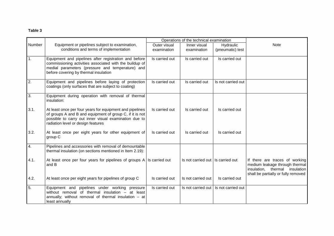
Table 3
Operations of the technical examination Number
Equipment or pipelines subject to examination,
сonditions and terms of implementation
Outer visual examination
Inner visual examination
Hydraulic (pneumatic) test
Note
1. Equipment and pipelines after registration and before commissioning activities associated with the buildup of medial parameters (pressure and temperature) and before covering by thermal insulation
Is carried out Is carried out Is carried out
2. Equipment and pipelines before laying of protection coatings (only surfaces that are subject to coating)
Is carried out Is carried out Is not carried out
3. Equipment during operation with removal of thermal insulation:
3.1. At least once per four years for equipment and pipelines of groups A and B and equipment of group C, if it is not possible to carry out inner visual examination due to radiation level or design features
Is carried out Is carried out Is carried out
3.2. At least once per eight years for other equipment of group C
Is carried out Is carried out Is carried out
4. Pipelines and accessories with removal of demountable thermal insulation (on sections mentioned in Item 2.19):
4.1. At least once per four years for pipelines of groups A and B
Is carried out Is not carried out Is carried out If there are traces of working medium leakage through thermal insulation, thermal insulation shall be partially or fully removed
4.2. At least once per eight years for pipelines of group C
Is carried out Is not carried out Is carried out
5. Equipment and pipelines under working pressure without removal of thermal insulation – at least annually; without removal of thermal insulation – at least annually
Is carried out Is not carried out Is not carried out
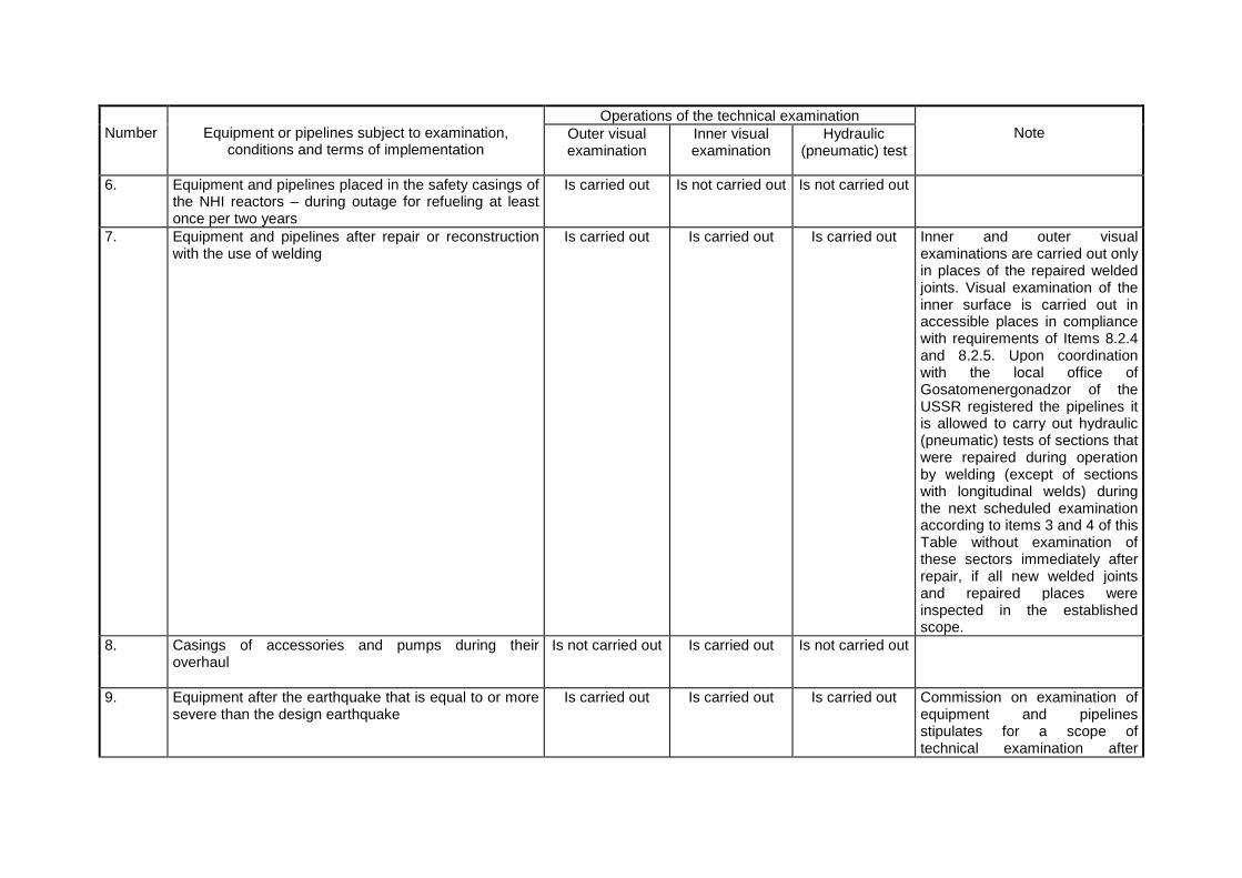
Operations of the technical examination Number
Equipment or pipelines subject to examination,
сonditions and terms of implementation
Outer visual examination
Inner visual examination
Hydraulic (pneumatic) test
Note
6. Equipment and pipelines placed in the safety casings of the NHI reactors – during outage for refueling at least once per two years
Is carried out Is not carried out Is not carried out
7. Equipment and pipelines after repair or reconstruction with the use of welding
Is carried out Is carried out Is carried out Inner and outer visual examinations are carried out only in places of the repaired welded joints. Visual examination of the inner surface is carried out in accessible places in compliance with requirements of Items 8.2.4 and 8.2.5. Upon coordination with the local office of Gosatomenergonadzor of the USSR registered the pipelines it is allowed to carry out hydraulic (pneumatic) tests of sections that were repaired during operation by welding (except of sections with longitudinal welds) during the next scheduled examination according to items 3 and 4 of this Table without examination of these sectors immediately after repair, if all new welded joints and repaired places were inspected in the established scope.
8. Casings of accessories and pumps during their overhaul
Is not carried out Is carried out Is not carried out
9. Equipment after the earthquake that is equal to or more severe than the design earthquake
Is carried out Is carried out Is carried out Commission on examination of equipment and pipelines stipulates for a scope of technical examination after
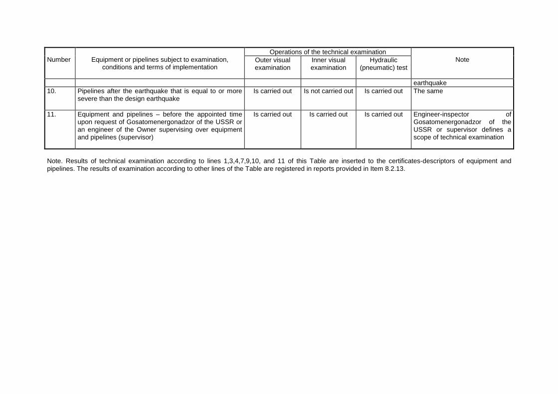
Operations of the technical examination Number
Equipment or pipelines subject to examination,
сonditions and terms of implementation
Outer visual examination
Inner visual examination
Hydraulic (pneumatic) test
Note
earthquake 10. Pipelines after the earthquake that is equal to or more
severe than the design earthquake
Is carried out Is not carried out Is carried out The same
11. Equipment and pipelines – before the appointed time upon request of Gosatomenergonadzor of the USSR or an engineer of the Owner supervising over equipment and pipelines (supervisor)
Is carried out Is carried out Is carried out Engineer-inspector of Gosatomenergonadzor of the USSR or supervisor defines a scope of technical examination
Note. Results of technical examination according to lines 1,3,4,7,9,10, and 11 of this Table are inserted to the certificates-descriptors of equipment and pipelines. The results of examination according to other lines of the Table are registered in reports provided in Item 8.2.13.
8.2.6. Technical examination of equipment and pipelines shall be carried out in a scope and in terms specified in Table 3. 8.2.7. Technical examination of equipment and pipelines having safety casings shall be carried out before their welding. 8.2.8. If devices checking of testing leakproofness of equipment and pipelines and their safety casings with the use of coolant leak analyzers, Detectors of radioactive gas occurrence, pressure detectors and other means stipulated for by the design are parts of the NPI with fast breeder reactors, it is allowed not to conduct the following activities within a scope of technical examination:
1) Visual examination of inner surface of equipment of primary and secondary circuits from the side of liquid metal coolant;
2) Visual examination of inner surface of safety casings of equipment and pipelines;
3) Visual examination of outer surfaces of equipment and pipelines coated by safety
casings. 8.2.9. In-service inspection of metal of equipment and pipelines shall precede the technical examination. Inspection results shall be analyzed prior to technical examination. 8.2.10. Commission appointed by the Order of the NPI Owner Manager carries out technical examination of equipment and pipelines subject to compliance with these Rules. The Commission works with participation and under supervision of the inspector of Gosatomenergonadzor of the USSR if technical examination of equipment and pipelines registered at the local office of Gosatomenergonadzor of the USSR is carried out. 8.2.11. The commission shall consist of the following members:
• The Engineer of the Owner supervising over equipment and pipelines (supervisor); • A person responsible for operability and safe operation of these equipment and
pipelines; • An engineer of the Metal Laboratory of the NPI; • Engineers of technical inspection services of mounting and repair organizations and
organizations involved upon agreement with mounting and repair organizations (if technical examinations are carried out after mounting or repair).
8.2.12. Before the technical examination the commission shall review and analyze the following documents:
1) Certificates-descriptors for equipment and pipelines and existence of records on the previous technical examination, metal inspection and repairs in them;
2) Data on violations of limits of safe operation occurred in operation and estimation
of their possible impact on the further operability and reliability. 8.2.13. The Management of the Owner of equipment and pipelines shall define specific date of technical examination of equipment and pipelines. This date shall not be later than the date indicated in the certificates-descriptors of equipment and pipelines. 8.2.14. Management of the Owner of equipment and pipelines shall inform the inspector of Gosatomenergonadzor of the USSR on the readiness of equipment and pipelines for the technical examination at least 10 days prior to it.
8.2.15. The local office of Gosatomenergonadzor of the USSR can postpone the technical examination of equipment and pipelines registered at the local office of Gosatomenergonadzor of the USSR but not more than for three months upon receiving the technically justified written application of the Management of the Owner of equipment and pipelines and in case of positive results of their visual examination in a working condition by the inspector of Gosatomenergonadzor of the USSR. 8.2.16. The technical examination of equipment and pipelines that are not registered at the structural units of Gosatomenergonadzor of the USSR can be postponed for not more than three months upon the written permission of the Chief Engineer or Manager of the Owner of equipment and pipelines. 8.2.17. Prior to technical examination equipment shall be shutdown, reliably isolated from all pressure sources, emptied from the working medium filling it. Surfaces subject to visual shall be cleaned of contamination, boiling scale, etc. The Designer shall develop and stipulate for in the detail design special methods for the visual examination of pipelines and equipment that cannot be emptied due to the technical reasons during the examination. Procedure for their visual examination coordinated with the Owner of equipment and pipelines and the local office of Gosatomenergonadzor of the USSR shall be developed. 8.2.18. Equipment and pipelines being in contact with radioactive coolant shall be carefully treated and cleaned by decontaminating solutions prior to technical examination and preparatory activities preceding it. This work shall be done in compliance with a procedure for safe implementation of activities and Health Standards and Rules. 8.2.19. If necessary, equipment and pipelines shall be equipped with stepladders, decks, platforms and other arrangements providing for safe implementation of visual examination of equipment and pipelines. 8.2.20. Special attention shall be drawn during visual examination to revealing of the following flaws:
1) On inner and outer surfaces of the base metal – cracks, tears, pits, cavities; 2) On inner and outer surfaces of welded joints – cracks, tears, undercuts, non-
compliances of shapes and sizes with requirements of drawings; 3) On surfaces of anticorrosion coatings – cracks, pores, fisheyes, corrosion
damages. 8.2.21. The commission develops reports on the results of technical examination [outer and inner visual examinations, hydraulic (pneumatic) test]. These reports include conclusions on a possibility of implementation of further operations of technical examination and a possibility of operation with indication of the permissible media parameters. Based on conclusions of the mentioned reports, inspection results and personal participation in the technical examination of equipment and pipelines registered at the structural units of Gosatomenergonadzor of the USSR the engineer-inspector of Gosatomenergonadzor of the USSR takes the final decision and records notes on the results of technical examination, parameters of working media acceptable during their operation and dates of the next technical examinations in the certificates-descriptors of these equipment and pipelines. A person implementing supervision at the Owner makes records in the certificates-descriptors of other equipment and pipelines. 8.2.22. If defects were revealed during operation, which existence prejudices operability of equipment and pipelines, the inspector of Gosatomenergonadzor of the USSR is authorized to prohibit operation of this equipment and request from the Management of the Owner of equipment and pipelines an opinion on causes of defects, a possibility and conditions of
further operation of equipment and pipelines from the specialized organizations or individual experts or carrying out of corresponding studies, if necessary. 8.2.23. If flaws were detected in the base metal or welded joint the results of the visual examination of the defective junction shall be recorded in a form of the report (Annex 12). This reports (one copy to any address) together with the extract from the factory certificate (Annex 13), strength analysis and data on experimental estimation of stresses and temperatures, expert opinion (in case of corrosion defects) are submitted to the ministry (agency) controlling the Owner of equipment and pipelines, Chief Designer of the reactor installation, Manufacture and ministry controlling it and the local office of Gosatomenergonadzor of the USSR. One copy of the report is inserted to the certificate-descriptor. Moreover protocols or reports according to items 7.7.7 and 7.8.11 that represent results of in-service metal inspection in the areas of defect detection are submitted to the mentioned organizations. A commission appointed by the ministry controlling the Owner of equipment and pipelines or by the Chief Engineer of the Owner (depending on the nature and scale of the revealed defects) makes a decision on measures for defect elimination and on a possibility of further operation of equipment and pipelines. The inspector of Gosatomenergonadzor of the USSR shall participate in this commission. Representatives of the Manufacturer (mounting organization), Designer and the leading metal science organization shall be members of this commission, if necessary. 8.3. Permission for implementation of commissioning activities and operation of the NPI systems 8.3.1. Commissions of Gosatomenergonadzor of the USSR issue a permission for implementation of commissioning activities concerned with putting of equipment and pipelines under the operational parameters and for operation of the NPI systems under the operational parameters based on the following:
1) Records of the inspector of Gosatomenergonadzor of the USSR and the supervisor in the certificates-descriptors for equipment and pipelines being a part of the NPI system on the permission of their operation under the operational parameters;
2) Results of check-up of:
• Compliance of equipment and pipelines connection with the design and requirements of these Rules;
• Availability of the educated and trained maintenance personnel and
engineering staff passing examination on the awareness with these Rules, operational rules and working procedures, as well as announcement on the working positions and their staffing;
• Availability of the approved working procedures and operational diagrams
and job descriptions; • Completion of the prior-operation metal inspection of equipment and
pipelines; • Actual readiness of equipment and pipelines for buildup of parameters
(coating by thermal insulation is completed, a well as adjustment of safety devices, equipping with control and measuring instrumentation, marking and painting, etc.);
• Readiness of support systems providing for operation of equipment and pipelines;
• Establishment of the appropriate mode of operation in the premises of
equipment and pipelines and a procedure for personnel access for implementation of activities;
• Availability of programs and techniques for tests carried out during
commissioning; • Arrangement of water and gas behavior; • Completion of all tests and examinations anticipated by the commissioning
program (in case of issuing a permission for operation). 8.3.2. The inspector of Gosatomenergonadzor of the USSR and the person implementing supervision at the Owner give a permission for putting equipment and pipelines under the operational parameters is registered in a form of a record in the certificates-descriptors. 8.3.3. Full completion of commissioning activities, getting to the design power level and comprehensive testing of the NPI shall precede the issuing of the permission for the permanent operation of equipment and pipelines. Programs of prior-operational metal inspections shall be completed during audit of equipment and pipelines; deficiencies detected during commissioning shall be eliminated. 8.3.4. The NPI Management shall obtain permission for the permanent operation of equipment and pipelines registered at the structural units of Gosatomenergonadzor of the USSR within 10 days after reaching the design power level and carrying out of the comprehensive testing. 8.3.5. The permission for the permanent operation of equipment and pipelines registered at the structural units of Gosatomenergonadzor is issued based on the written application of the Management of the Owner and positive results of the NPI check-up. Data on completeness and quality of implementation of the commissioning programs, process of reaching of the design power level, as well as data on elimination of the revealed defects on the registered equipment and pipelines shall be presented in the written application. During the NPI check-up carried out according to Item 8.3.1 the Commission shall become convinced of the following by examining of documentation confirming implementation of all examinations required by these Rules and other documents regulating an order for implementation of such examination:
• Equipment and pipelines function normally and limits and conditions of safe operation of equipment and pipelines are met;
• Arrangement and maintaining of water chemistry and gas behavior; • Normal performance and operability of control and measuring instrumentation and
safety devices, process protections and interlocks of equipment and pipelines; • Compliance of equipment and pipelines connection with requirements of these Rules; • Availability of the certified maintenance personnel and engineering staff passing
examination of their knowledge; • Availability of a job description for a person responsible for operability and safe
operation of equipment and pipelines;
• Availability of the process procedures, rules and diagrams for the personnel carrying out maintenance of equipment and pipelines.
8.3.6. The inspector of Gosatomenergonadzor of the USSR registers permission for the permanent operation by a record in the certificates-descriptors for equipment and pipelines with indication of the authorized parameters (pressure and temperature) for operation of equipment and pipelines and a date of the next technical examination. 8.3.7. A person who is responsible for operability and safe operation of equipment and pipeline issues the permission for the permanent operation of equipment and pipelines that shall not be registered at the structural units of Gosatomenergonadzor of the USSR and records information on the permitted parameters and a date of the next technical examination in the certificates-descriptors. 9. OPERATION OF EQUIPMENT AND PIPELINES. GENERAL RE QUIREMENTS 9.1. General requirements 9.1.1. The NPI Management must ensure reliable and safe operation of equipment and pipelines, supervision over them, metal inspection and repair. For this purpose the appropriate structural units shall be established. Before the registration of equipment and pipelines the NPI Management shall issue an Order assigning equipment and pipelines to the respective structural units and appointing persons responsible for operability and safe operation of equipment and pipelines from the heads of these structural units. 9.1.2. The NPI Manager and Chief Engineer bear responsibility for the general management and safe operation of equipment and pipelines. 9.1.3. At any NPI staffing, training and examination of engineering and maintenance personnel shall be completed prior to start of commissioning of equipment and pipelines. Requirements for personnel professional skills, procedure on preparation for examinations shall comply with OPB-88. 9.1.4. Before startup of the NPI equipment operation design process protections shall be checked and put into operation and interlocks of the process protections put into operation shall be switched on during the whole time of equipment operation. It is prohibited to shutdown operable process protections. Only in the following cases shutdown of process protections is permitted:
• A necessity to shutdown a protection specified by the operational procedure; • Obvious failure of the protection.
The protection shall be shutdown only upon the Order of the NPI Chief Engineer with the obligatory notification of the inspection office of Gosatomenergonadzor of the USSR. 9.1.5. Operational rules developed in compliance with OPB are the main document defining safe operation of the NPI. Requirements of these Rules, technical specifications and procedures on mounting and operation of equipment and pipelines shall be taken into consideration in development of the operational rules. 9.1.6. Before registration of equipment and pipelines at the structural units of Gosatomenergonadzor of the USSR the NPI Management shall provide for development of operational procedures for these equipment and pipelines based on the rules in force, requirements of design and engineering documentation and approved operational rules. The following information shall be presented in the procedures on equipment operation:
a) An order of preparation for the startup, an order of startup, shutdown and maintenance during normal operation; b) Cases when equipment and pipelines shall be shutdown immediately, in particular:
• If cracks and flaws in base metal and welded joints of equipment and
pipelines are detected; • If supports and hangers are damaged; • If there is a buildup of pressure, temperature or activity inside the unattended
premises where equipment and pipelines are located; • If noises, vibrations and shocks appear in equipment and pipelines; • Cases stipulated for by the design and operational procedures; • If pressure is higher than working pressure by more than 15 % and continue
to rise in spite of compliance with all requirements given in procedures; • If 50% of safety devices are faulty; • If pressure or level measuring devices are faulty;
c) Cases when measures for shutdown of equipment and pipelines shall be taken according to the schedule, in particular:
• If leaks are detected in flange joints; • If coolant deterioration exceeds the established standards;
d) Actions of personnel in case of abnormalities and failures of equipment and pipelines; e) An order of shutdown equipment and pipelines for their repair.
9.1.7. A procedure for testing and adjustment of safety valves shall be developed at any NPI. Requirements of Item 6.2 of these Rules, requirements of the Manufacturer procedures shall be considered in this procedure. Administrative and technical measures to avoid accident occurrence and personnel injuries during implementation of testing and adjustment of safety valves shall be provided in this procedure. 9.1.8. Operational procedures are provided on working places according to the list of technical documentation. The NPI Chief Engineer (Manager) approves a list of technical documentation for any working place. The members of maintenance personnel shall put their signatures that were informed on the content of procedures. The operational procedures shall be revised based on the results of commissioning activities at the NPI. 9.1.9. If a state or operational conditions of equipment were changed, the corresponding changes shall be inserted to the operational instructions. The maintenance personnel shall be informed on these changes and this fact shall be recorded in the logbook of Orders. Operational procedures shall be revised at least once per three years. 9.1.10. Equipment where hydrogen accumulation during operation is possible shall be equipped with monitoring means. Monitoring of hydrogen concentration shall be carried out
automatically or by the laboratory analyses ate least once per a shift. More that 3% hydrogen concentration in gas is not allowed. Equipment subject to monitoring with regard to hydrogen concentration shall be indicated in the procedure based on the design. 9.1.11. Water chemistry of nuclear power plants and coolant quality shall comply with requirements of standards. For tests and research nuclear reactors water chemistry is defined by the design or is stipulated by the procedure. 9.1.12. Operability of process protections, safety and automatic devices, gears and control and measuring instrumentation shall be checked before startup of equipment after repair or long-term shutdown (for more than three days). 9.1.13. At any NPI schedule of startup, shutdown and loading of the main and auxiliary equipment shall be developed. Check-up of actuation of backup pumps, planned switch from the working pumps to the backup pumps should be done according to the schedule. 9.1.14. At the NPI with reactors and pipelines having safety casings measures on the immediate shutdown of equipment and pipelines shall be taken in case of actuation of coolant leakage alarm systems. 9.1.15. Prior to pressure buildup in the high pressure systems low pressure equipment and pipelines of the auxiliary systems (systems of cooling down, filling, emptying, low pressure compressed gas supply systems) shall be disconnected from that systems of high pressure. Design and operational procedures shall provide for administrative and technical measures to avoid faulty connection of low-pressure systems to the high-pressure systems. 9.1.16. It is prohibited to carry our different research studies and experiments on the operating equipment and pipelines without preliminary coordination with the Chief Engineer, General Designer, Scientific supervisor and Gosatomenergonadzor of the USSR and permission of the ministry (agency) controlling this NPI. 9.1.17. Starting form the commissioning stages a number of operational cycles of equipment, neutron fluence, duration of operation at the power level and other parameters determining an operational lifetime of equipment in compliance with strength analysis and technical specifications shall be recorded at the NPI. 9.2. Special requirements 9.2.1. Safety devices on the pressurizer at the shutdown water-water reactor with the reactor vessel closed by the head shall be in the operable state (except of cases when hydraulic tests are carried out). 9.2.2. Change of equipment parameter limits (design pressure, design temperature, maximum power level, coolant flow rate, rates of heating up and cooling down, maximum neutron fluence on the reactor vessel and channels) can be authorized only based on the technical solution justified by the appropriate calculations or experiments and amendment to the design approved according to the established procedure. This technical solution is developed by the Owner of equipment and pipelines and coordinated with the Chief Engineer, Scientific supervisor, General Designer, Manufacturer (mounting organization) and with Gosatomenergonadzor of the USSR, if necessary. Changes resulted from the taken technical solutions shall be reflected in certificates-descriptors for equipment and pipelines. 9.3. General requirements for arranging of repair o f equipment and pipelines 9.3.1. Requirements for implementation of scheduled preventive maintenances approved by the ministry (agency) controlling an NPI shall be met during operation of equipment and pipelines of this NPI.
Changing of dates of the scheduled preventive maintenance and reduction of its scope can be allowed only in exceptional cases upon the written permission of the ministry (agency) controlling this NPI coordinated with the structural units of Gosatomenergonadzor of the USSR. 9.3.2. Dates of scheduled preventive maintenances and overhauls of equipment and pipelines shall be defined with accounting of dates of technical examination of equipment and pipelines, in-service metal inspection, time of equipment operation between repairs according to requirements of technical specifications and procedures of the Manufacturers. 9.3.3. Schedule of repair activities shall provide in particular the following:
а) Preparation and implementation of technical examinations of equipment and pipelines; b) Preparation and implementation of in0service metal inspection; c) Preparation and implementation of testing of protective and safety devices.
9.3.4. Sealing of detachable joints of equipment and pipelines shall be carried out according to the process procedure with the use of special tool preventing creation of unacceptable stresses in the fasteners. 9.3.5. Values of stud tightening with controlled stretching shall be presented in a form of reports and be registered in special logbooks. 9.3.6. Repair or other activities with the detachable joints of equipment and pipelines being under pressure are not allowed, except of special operations on the remote reloading of fuel assemblies without shutdown of the reactor with the use of special machines and mechanisms. 9.3.7. Measures to avoid contamination of inner cavities or getting missiles there shall be taken during implementation of repair activities associated with unsealing of equipment and pipelines. 9.3.8. Welding at equipment and pipelines being under pressure is prohibited. 10. CONTROL OVER COMPLIANCE WITH THE RULES Gosatomenergonadzor of the USSR shall implement control over compliance with these Rules according to the Statute of Gosatomenergonadzor of the USSR and directives, procedures and other guiding materials of Gosatomenergonadzor of the USSR. 11. INVESTIGATION OF ACCIDENTS, FAILURES AND CASUAL TIES 11.1. Investigation of accidents, failures and casualties occurred in operation of the NPI equipment and pipelines shall be carried out in accordance with Provisions for the order of investigation of operational events at the installations of nuclear power engineering and procedures of Gosatomenergonadzor of the USSR. 11.2. The Management of the Owner of equipment and pipelines must immediately notify the local office of Gosatomenergonadzor of the USSR on any accident, failure, damage, defects of equipment and pipelines, actuation and failed fitting of safety valves. 12. CONCLUSION Necessity and terms of putting of existing and operating equipment and pipelines as well as those being under manufacture, mounting or reconstruction within the period of these Rules enforcement to the compliance with these Rules are specified individually for any specific

case upon the statement of the corresponding ministries (agencies) and are coordinated with Gosatomenergonadzor of the USSR. In individual cases when compliance with some requirements of these Rules is impossible due to technical reasons, it is allowed to prepare justified technical resolutions developed by the Designer, Manufacturer (mounting organization), the Owner of equipment and pipelines depending on the responsibility of each of them according to Items 1.4.3-1.4.5. The mentioned technical resolutions shall be coordinated with all organizations listed above, as well as with the leading material science organization, if those resolutions are within their responsibility, and with Gosatomenergonadzor – in all cases.
ANNEX 1 (reference annex)
MAIN TERMS AND DEFINITIONS
Term Definition
Pipelines A set of components and assembly units in a form of pipes with components relevant to them (manifolds, tee bends, passages, relief branch pipes, accessories, etc.) intended for transport of working medium from one equipment unit to another
Pump case A set of assembly units and pump components (except of built-in) that form a tank bounded pipe branches and end seals.
Isolation device Isolation accessories (valve, gate valve, tap valve, etc.) or a combination of some types of these accessories (including drainages and air taps between them) intended for cutting off systems, equipment and pipeline sections from each other, including fast acting reducing devices.
Safety device Safety accessories of all types, membranes, hydraulic gates or their combination (including pipeline bundle between them) intended for protection of equipment and pipeline systems against pressure excess by medium removal
Elbow Component or assembly unit of the pipeline where direction of internal medium flow id changed
Bend Elbow made of a pipe by bending strain
Stamped-welded elbow Elbow made of a plate, pipe or forged piece with the use of stamping and welding
Stamped elbow Elbow made of a pipe or forged piece by stamping without welding
Sector-type elbow or branch
Elbow or branch made of pipe sections welded with an angle between them
Welded passage Passage of a pipeline with a conic part that has longitudinal welded joints
Normal operational conditions (for equipment and pipelines)
Conditions for operation under operational modes stipulated for by the planned operational rules of the NPI (stationary mode, startup, functioning of control rods, change of reactor power, shutdown)
Violation of normal operational conditions (for equipment and pipelines)
Any deviation from normal operational conditions (with regard to pressure, temperature, loads, etc.) that requires reactor shutdown for elimination of those deviations without actuation of emergency core cooling systems
Emergency (for equipment and pipelines)
Any deviation from normal operational conditions, which consequences can result in such failure of reactor core cooling that actuation of the emergency core cooling system will be necessary
Working pressure Maximum surplus pressure in equipment and pipelines under normal operational conditions that is defined with accounting of hydraulic friction and hydrostatic pressure
Design pressure Maximum surplus pressure in equipment and pipelines under normal operational conditions that is used in strength analysis for definition of the main dimensions. The Manufacturer permits operation of this equipment or pipeline under this pressure in case of operation under
Term Definition design temperature and normal operational conditions. For safety casings the design pressure is the maximum surplus pressure occurred in case of sealing failure of protected equipment and pipelines (including emergency)
Design temperature Wall temperature of equipment or pipeline that is equal to maximum average value of temperatures on its outer and inner surfaces in the same cross section under normal operational conditions (for parts of nuclear reactor vessel the design temperature is defined with accounting of internal heat generation as an average integral value of temperature distribution along the thickness of the vessel wall)
Design organization Organization that carries out design of equipment or individual assembly units and component parts of pipelines; or organization that designs layout of equipment and pipelines within the NPI bounds
Mounting organization Organization that carries our mounting of equipment and pipelines at the NPI and/or develops mounting technology
Leading material science organization
Organization that is in charge of material selection, welding and quality assurance in manufacture of equipment and pipelines
Manufacturer Enterprise manufacturing equipment and pipelines, their assembly units and component parts
Owner of equipment and pipelines
Enterprise that operates NPI equipment and pipelines
Scientific supervisor Organization that carries out scientific leadership of the reactor installation designing
Note. Terms having general technical meaning or terms, which
definitions are given in other standards or regulatory documentation, are not presented in this Annex.
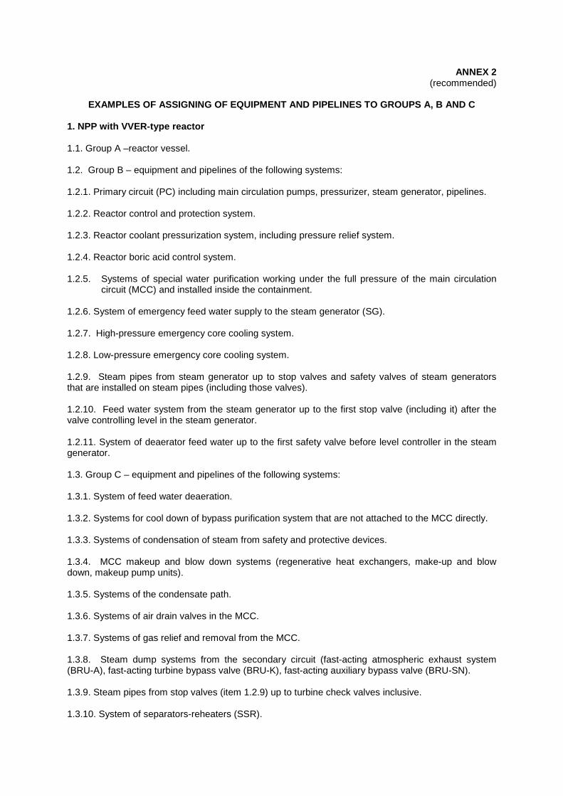
ANNEX 2 (recommended)
EXAMPLES OF ASSIGNING OF EQUIPMENT AND PIPELINES TO GROUPS A, B AND C
1. NPP with VVER-type reactor 1.1. Group A –reactor vessel. 1.2. Group B – equipment and pipelines of the following systems: 1.2.1. Primary circuit (PC) including main circulation pumps, pressurizer, steam generator, pipelines. 1.2.2. Reactor control and protection system. 1.2.3. Reactor coolant pressurization system, including pressure relief system. 1.2.4. Reactor boric acid control system. 1.2.5. Systems of special water purification working under the full pressure of the main circulation
circuit (MCC) and installed inside the containment. 1.2.6. System of emergency feed water supply to the steam generator (SG). 1.2.7. High-pressure emergency core cooling system. 1.2.8. Low-pressure emergency core cooling system. 1.2.9. Steam pipes from steam generator up to stop valves and safety valves of steam generators that are installed on steam pipes (including those valves). 1.2.10. Feed water system from the steam generator up to the first stop valve (including it) after the valve controlling level in the steam generator. 1.2.11. System of deaerator feed water up to the first safety valve before level controller in the steam generator. 1.3. Group C – equipment and pipelines of the following systems: 1.3.1. System of feed water deaeration. 1.3.2. Systems for cool down of bypass purification system that are not attached to the MCC directly. 1.3.3. Systems of condensation of steam from safety and protective devices. 1.3.4. MCC makeup and blow down systems (regenerative heat exchangers, make-up and blow down, makeup pump units). 1.3.5. Systems of the condensate path. 1.3.6. Systems of air drain valves in the MCC. 1.3.7. Systems of gas relief and removal from the MCC. 1.3.8. Steam dump systems from the secondary circuit (fast-acting atmospheric exhaust system (BRU-A), fast-acting turbine bypass valve (BRU-K), fast-acting auxiliary bypass valve (BRU-SN). 1.3.9. Steam pipes from stop valves (item 1.2.9) up to turbine check valves inclusive. 1.3.10. System of separators-reheaters (SSR).
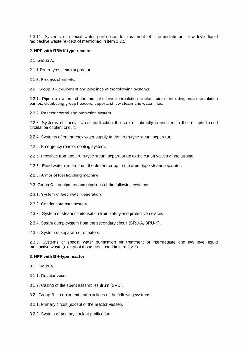
1.3.11. Systems of special water purification for treatment of intermediate and low level liquid radioactive waste (except of mentioned in item 1.2.5). 2. NPP with RBMK-type reactor 2.1. Group A. 2.1.1.Drum-type steam separator. 2.1.2. Process channels. 2.2. Group B – equipment and pipelines of the following systems: 2.2.1. Pipeline system of the multiple forced circulation coolant circuit including main circulation pumps, distributing group headers, upper and low steam and water lines. 2.2.2. Reactor control and protection system. 2.2.3. Systems of special water purification that are not directly connected to the multiple forced circulation coolant circuit. 2.2.4. Systems of emergency water supply to the drum-type steam separator. 2.2.5. Emergency reactor cooling system. 2.2.6. Pipelines from the drum-type steam separator up to the cut off valves of the turbine. 2.2.7. Feed water system from the deaerator up to the drum-type steam separator. 2.2.8. Armor of fuel handling machine. 2.3. Group C – equipment and pipelines of the following systems: 2.3.1. System of feed water deaeration. 2.3.2. Condensate path system. 2.3.3. System of steam condensation from safety and protective devices. 2.3.4. Steam dump system from the secondary circuit (BRU-A, BRU-K). 2.3.5. System of separators-reheaters. 2.3.6. Systems of special water purification for treatment of intermediate and low level liquid radioactive waste (except of those mentioned in item 2.2.3). 3. NPP with BN-type reactor 3.1. Group A. 3.1.1. Reactor vessel. 3.1.2. Casing of the spent assemblies drum (SAD). 3.2. Group B – equipment and pipelines of the following systems: 3.2.1. Primary circuit (except of the reactor vessel). 3.2.2. System of primary coolant purification.
3.2.3. System for drainage and filling of the primary circuit by coolant. 3.2.4. System of primary circuit gas pressure suppression (up to the first valve from the reactor side). 3.2.5. System of primary coolant sampling. 3.2.6. Safety casing of the reactor. 3.2.7. System of the secondary circuit (steam generator, electric pump unit, main pipelines with safety casings, including tie-ins of auxiliary systems up to the first valve inclusive from the side of main pipelines). 3.2.8. Steam generator emergency protection system with regard to sodium (SG EPS). 3.2.9. System of reactor cool down by air heat exchangers (AHE) on sodium side. 3.2.10. System of secondary circuit pressure suppression (up to the first valve from the side of the main equipment of the secondary circuit). 3.2.11. System of SAD cooling with regard to sodium. 3.2.12. Tertiary circuit system (equipment and pipelines of the main steam-water circuit except of condensate path system up to the deaerator inclusive as well as tie-in of auxiliary systems up to the first valve inclusive from the side of the main pipelines). 3.3. Group C – equipment and pipelines of the following systems: 3.3.1. Condensate path system of the tertiary circuit. 3.3.2. System of secondary coolant purification. 3.3.3. System of draining and filling of the secondary coolant circuit. 3.3.4. Coolant preparation system. 3.3.5. Secondary coolant sampling system. 3.3.6. Steam generator emergency protection system with regard to the steam-water circuit. 3.3.7. Feed water deaeration system. 3.3.8. System of special water purification for treatment of intermediate and high level liquid radioactive waste. 3.3.9. Purification system of gas of the primary circuit gas blanket.
ANNEX 3 (obligatory)
CERTIFICATE-DESCRIPTOR OF THE NPI VESSEL
This Annex sets a format of the certificate-descriptor for a vessel. 1. Certificate-descriptor for a vessel is the main document that confirms vessel behavior, quality of manufacture and mounting, its operability during operation and compliance with production-process documentation. 2. The Annex does not set a mandatory filling in of all tables and columns of the certificate-descriptor. Type and scope of data subject to insertion into the certificate-descriptor are defined by technical specifications for the product or by standards. 3. The Manufacturer prepares the certificate-descriptor for a vessel and forwards it to the customer. Data to be presented in the certificate-descriptor taking into account instructions of Item 2 of this Annex are presented in Tables P 3.1-P.3.8 (to be filled in by the Manufacturer) and Tables P 3.9 – P 3.14 (to be filled in by the mounting organization and the Owner). An enterprise or organization carrying out mounting (completion) of the vessel at the Owner of equipment prepares a certificate on mounting according to Annex 7 during mounting (completion) of the vessel. This certificate shall be enclosed to the certificate-descriptor of the vessel. Below is a set of documents that shall be submitted together with the certificate-descriptor for the vessel:
1) A set of drawings (general view and/or assembly units) that shall give a possibility to check the main dimensions and control vessel compliance with requirements of the design and to check equipping with accessories and safety devices;*
2) Strength analysis for components working under pressure or extract** from it with
indication of the calculation identification;
3) Tables of quality control of welded joints and base materials***;
4) Certificates-descriptors (certificates) for accessories supplied together with the vessel;
5) Technical description and operational manual including requirements for storage, mothballing, de-mothballing, commissioning, mounting and safety engineering (labor safety), as well as a list of devices for inspection, measurements, control, alarm and automation that are parts of the NPI vessel shipment; diagram or instructions for their installation;
6) Documentation on non-compliances with design documentation coordinated with
Gosatomenergonadzor of the USSR. 4. Table formats of certificates-descriptors are obligatory. Change of paper size and size of columns, as well as replacement of tables by copies of certificates providing necessary data is allowed.
* The Designer or Manufacturer (in coordination with the Designer) defines a set of drawings. ** Extract from strength analysis shall present the following: a list of the analyzed construction units and loads and temperature impact affecting them; a list of operational modes (including violations of normal operational conditions and emergencies), for which the analysis was done; a number of loading cycles under each operational mode; neutron fluence on the reactor vessel; data on strength assessment according to all criteria, that are required by standards on strength analysis. *** Are enclosed if it is required by design and process documentation.
5. The Owner shall store certificates-descriptors together with enclosures and results of NPP equipment inspections during the whole operational lifetime. 6. The manufacture of equipment stores originals of certificates and reports on the inspection results during the whole service life of the vessel. If they are forwarded to the Owner, this fact shall be reflected in the certificate-descriptor. 7. It is allowed to reduce a scope of data presented in the certificate-descriptor by excluding data that are not relevant to this vessel. It shall be done in coordination with the Designer. 8. Space for translation of the text by the owner of equipment to the other language shall be left on any page of certificates-descriptors of the exported vessels and in the enclosed documentation. 9. Upon request of Gosatomenergonadzor of the USSR additional data can be included into certificates-descriptions.
CERTIFICATE-DESCRIPTOR (name of the vessel) Registration number No N o t e s : 1. The registration number is assigned by the local office of Gosatomenergonadzor of the USSR (in
case of registration of the vessel in that local office) or by the Owner (in case of vessel registration at that enterprise).
2. Free columns are left for translation.
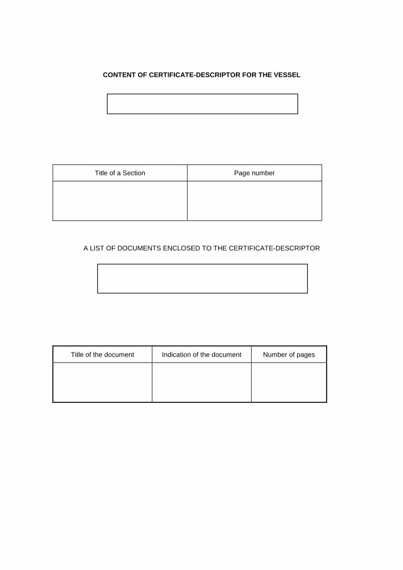
CONTENT OF CERTIFICATE-DESCRIPTOR FOR THE VESSEL
Title of a Section Page number
A LIST OF DOCUMENTS ENCLOSED TO THE CERTIFICATE-DESCRIPTOR
Title of the document Indication of the document Number of pages
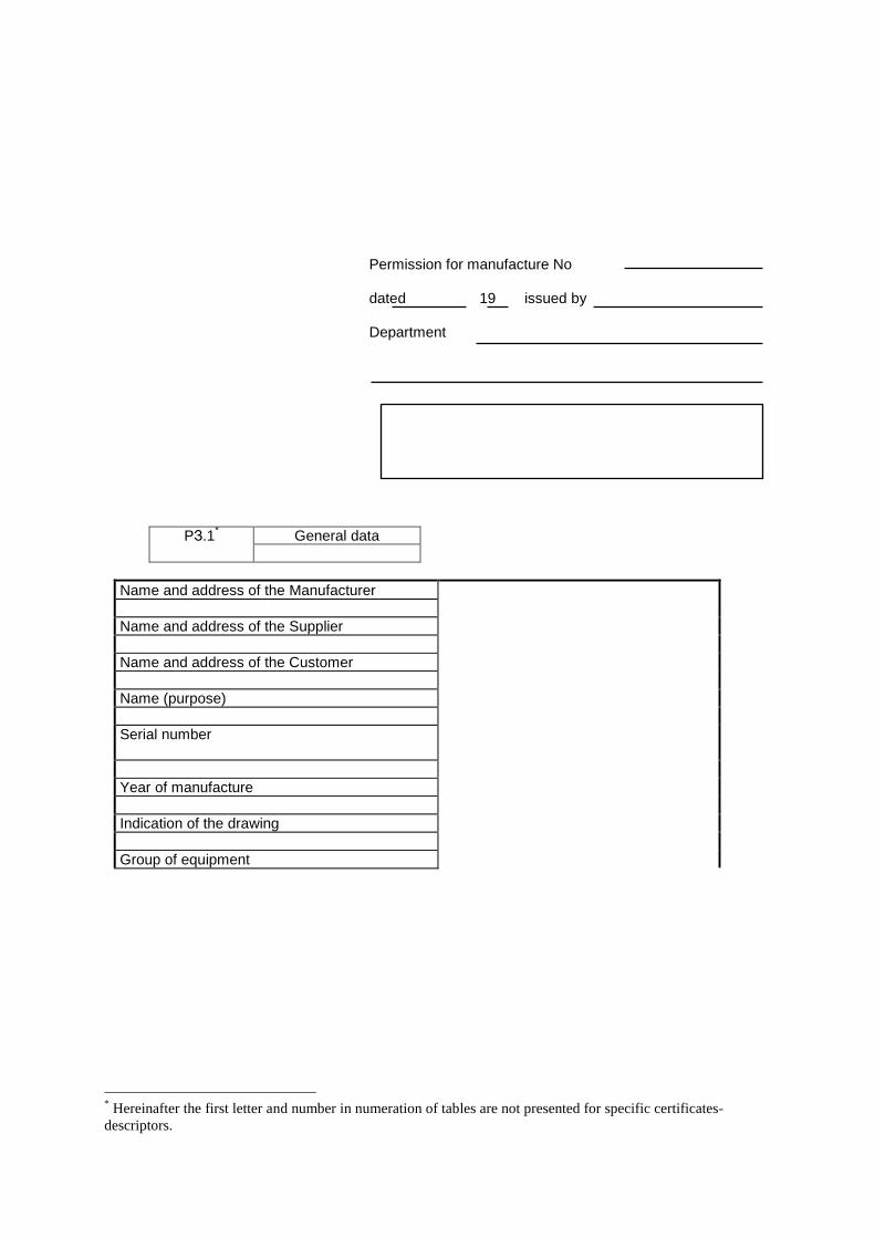
Permission for manufacture No dated 19 issued by Department
General data PЗ.1*
Name and address of the Manufacturer Name and address of the Supplier Name and address of the Customer Name (purpose) Serial number
Year of manufacture Indication of the drawing Group of equipment
* Hereinafter the first letter and number in numeration of tables are not presented for specific certificates-descriptors.
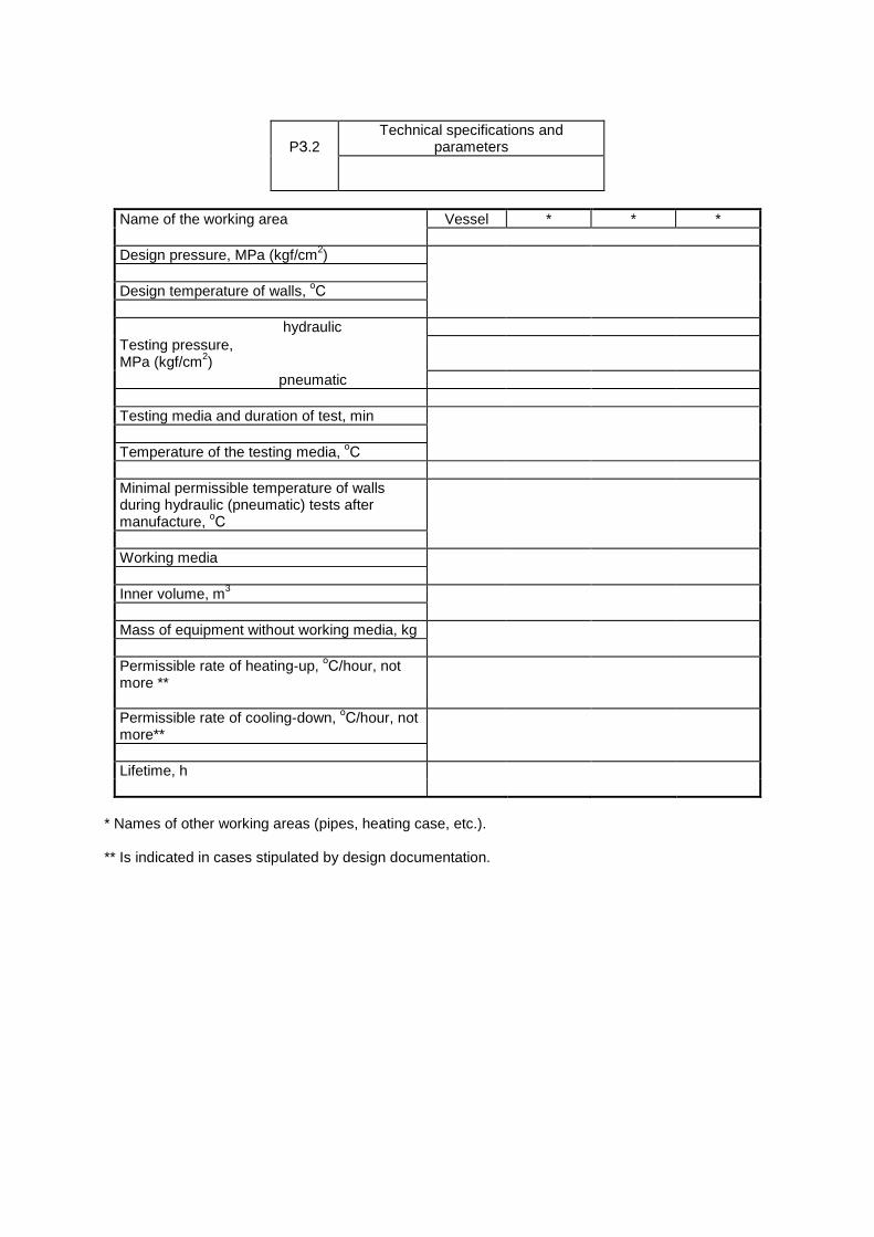
Technical specifications and
parameters
PЗ.2
Name of the working area Vessel * * * Design pressure, MPa (kgf/cm2) Design temperature of walls, оС hydraulic Testing pressure, MPa (kgf/cm2)
pneumatic Testing media and duration of test, min Temperature of the testing media, оС Minimal permissible temperature of walls during hydraulic (pneumatic) tests after manufacture, оС
Working media Inner volume, m3 Mass of equipment without working media, kg Permissible rate of heating-up, оС/hour, not more **
Permissible rate of cooling-down, оС/hour, not more**
Lifetime, h
* Names of other working areas (pipes, heating case, etc.). ** Is indicated in cases stipulated by design documentation.
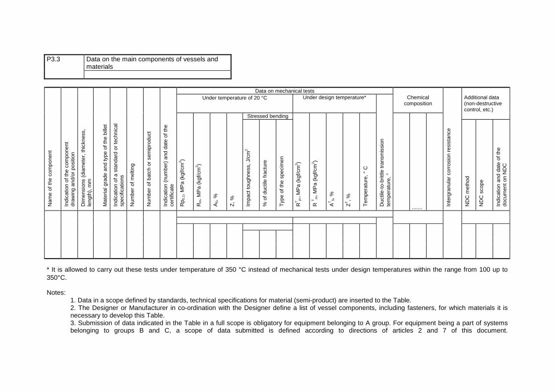
P3.3 Data on the main components of vessels and
materials Data on mechanical tests Under temperature of 20 °C Under design temperature* Chemical
composition Additional data
(non-destructive control, etc.)
Stressed bending
Nam
e of
the
com
pone
nt
Indi
catio
n of
the
com
pone
nt
draw
ing
and/
or p
ositi
on
Dim
ensi
ons
(dia
met
er, t
hick
ness
, le
ngth
), m
m
Mat
eria
l gra
de a
nd ty
pe o
f the
bill
et
Indi
catio
n of
a s
tand
ard
or te
chni
cal
spec
ifica
tions
Num
ber
of m
eltin
g
Num
ber
of b
atch
or
sem
ipro
duct
Indi
catio
n (n
umbe
r) a
nd d
ate
of th
e ce
rtifi
cate
Rp 0
.2, M
Pa
(kgf
/cm
2 )
Rm, M
Pa
(kgf
/cm
2 )
A5,
%
Z, %
Impa
ct to
ughn
ess,
J/c
m2
% o
f duc
tile
frac
ture
Typ
e of
the
spec
imen
RT
p0,2
, MP
a (k
gf/c
m2 )
R T
m, M
Pa
(kgf
/cm
2 )
AT
5, %
ZT, %
Tem
pera
ture
, ° C
Duc
tile-
to-b
rittle
tran
smis
sion
te
mpe
ratu
re, °
.......
Inte
rgra
nula
r co
rros
ion
resi
stan
ce
ND
C m
etho
d
ND
C s
cope
Indi
catio
n an
d da
te o
f the
do
cum
ent o
n N
DC
* It is allowed to carry out these tests under temperature of 350 °C instead of mechanical tests under design temperatures within the range from 100 up to 350°C. Notes:
1. Data in a scope defined by standards, technical specifications for material (semi-product) are inserted to the Table. 2. The Designer or Manufacturer in co-ordination with the Designer define a list of vessel components, including fasteners, for which materials it is necessary to develop this Table. 3. Submission of data indicated in the Table in a full scope is obligatory for equipment belonging to A group. For equipment being a part of systems belonging to groups B and C, a scope of data submitted is defined according to directions of articles 2 and 7 of this document.
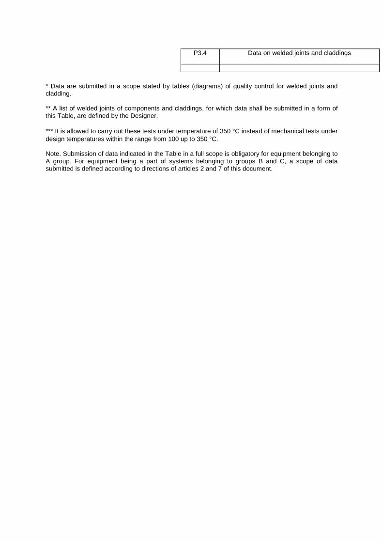
* Data are submitted in a scope stated by tables (diagrams) of quality control for welded joints and cladding. ** A list of welded joints of components and claddings, for which data shall be submitted in a form of this Table, are defined by the Designer. *** It is allowed to carry out these tests under temperature of 350 °C instead of mechanical tests under design temperatures within the range from 100 up to 350 °C. Note. Submission of data indicated in the Table in a full scope is obligatory for equipment belonging to A group. For equipment being a part of systems belonging to groups B and C, a scope of data submitted is defined according to directions of articles 2 and 7 of this document.
P3.4 Data on welded joints and claddings
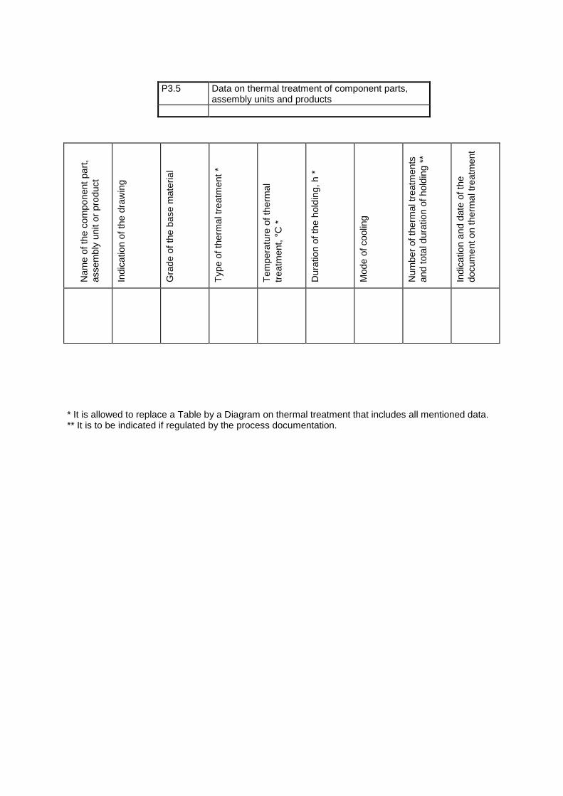
Nam
e of
the
com
pone
nt p
art,
asse
mbl
y un
it or
pro
duct
Indi
catio
n of
the
draw
ing
Gra
de o
f the
bas
e m
ater
ial
Typ
e of
ther
mal
trea
tmen
t *
Tem
pera
ture
of t
herm
al
trea
tmen
t, °C
*
Dur
atio
n of
the
hold
ing,
h *
Mod
e of
coo
ling
Num
ber
of th
erm
al tr
eatm
ents
an
d to
tal d
urat
ion
of h
oldi
ng *
*
Indi
catio
n an
d da
te o
f the
do
cum
ent o
n th
erm
al tr
eatm
ent
* It is allowed to replace a Table by a Diagram on thermal treatment that includes all mentioned data. ** It is to be indicated if regulated by the process documentation.
P3.5 Data on thermal treatment of component parts, assembly units and products
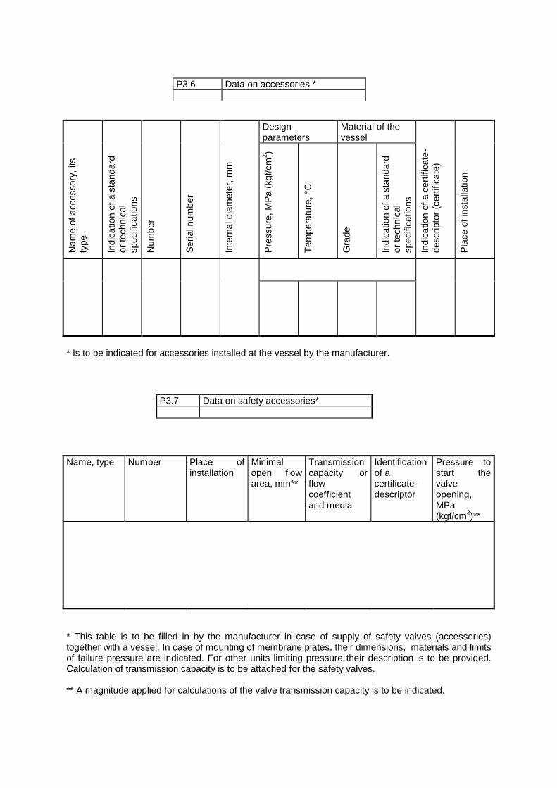
Design
parameters Material of the vessel
Nam
e of
acc
esso
ry, i
ts
type
Indi
catio
n of
a s
tand
ard
or te
chni
cal
spec
ifica
tions
Num
ber
Ser
ial n
umbe
r In
tern
al d
iam
eter
, mm
P
ress
ure,
MP
a (k
gf/c
m2 )
Tem
pera
ture
, °C
Gra
de
Indi
catio
n of
a s
tand
ard
or te
chni
cal
spec
ifica
tions
Indi
catio
n of
a c
ertif
icat
e-de
scrip
tor
(cer
tific
ate)
Pla
ce o
f ins
talla
tion
* Is to be indicated for accessories installed at the vessel by the manufacturer. Name, type Number Place of
installation Minimal open flow area, mm**
Transmission capacity or flow coefficient and media
Identification of a certificate-descriptor
Pressure to start the valve opening, MPa (kgf/cm2)**
* This table is to be filled in by the manufacturer in case of supply of safety valves (accessories) together with a vessel. In case of mounting of membrane plates, their dimensions, materials and limits of failure pressure are indicated. For other units limiting pressure their description is to be provided. Calculation of transmission capacity is to be attached for the safety valves. ** A magnitude applied for calculations of the valve transmission capacity is to be indicated.
P3.6 Data on accessories *
P3.7 Data on safety accessories*
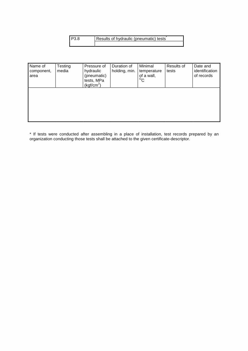
Name of component, area
Testing media
Pressure of hydraulic (pneumatic) tests, MPa (kgf/cm2)
Duration of holding, min.
Minimal temperature of a wall, ОС
Results of tests
Date and identification of records
* If tests were conducted after assembling in a place of installation, test records prepared by an organization conducting those tests shall be attached to the given certificate-descriptor.
P3.8 Results of hydraulic (pneumatic) tests*
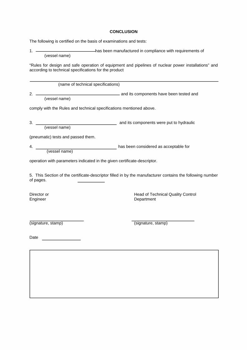
CONCLUSION The following is certified on the basis of examinations and tests: 1. has been manufactured in compliance with requirements of
(vessel name) “Rules for design and safe operation of equipment and pipelines of nuclear power installations” and according to technical specifications for the product (name of technical specifications) 2. and its components have been tested and
(vessel name) comply with the Rules and technical specifications mentioned above. 3. and its components were put to hydraulic (vessel name) (pneumatic) tests and passed them. 4. has been considered as acceptable for (vessel name) operation with parameters indicated in the given certificate-descriptor. 5. This Section of the certificate-descriptor filled in by the manufacturer contains the following number of pages. Director or Head of Technical Quality Control Engineer Department (signature, stamp) (signature, stamp) Date
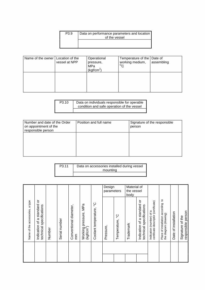
Name of the owner Location of the
vessel at NPP Operational pressure, MPa (kgf/cm2)
Temperature of the working medium, ОС
Date of assembling
Number and date of the Order on appointment of the responsible person
Position and full name Signature of the responsible person
Design
parameters Material of the vessel body
Nam
e of
the
acce
ssor
ies,
a ty
pe
Indi
catio
n of
a s
tand
ard
or
tech
nica
l spe
cific
atio
ns
Num
ber
Ser
ial n
umbe
r
Con
vent
iona
l dia
met
er,
mm
Wor
king
pre
ssur
e, M
Pa
(kgf
/cm
2 )
Coo
lant
tem
pera
ture
, °C
Pre
ssur
e,
Tem
pera
ture
, °C
Tra
dem
ark
Indi
catio
n of
a s
tand
ard
or
tech
nica
l spe
cific
atio
ns
Indi
catio
n (n
umbe
r) o
f a
cert
ifica
te-d
escr
ipto
r (c
ertif
icat
e)
Pla
ce o
f ins
talla
tion
acco
rdin
g to
th
e di
agra
m (
draw
ing)
Dat
e of
inst
alla
tion
Sig
natu
re o
f the
re
spon
sibl
e pe
rson
P3.9 Data on performance parameters and location of the vessel
P3.10 Data on individuals responsible for operable condition and safe operation of the vessel
P3.11 Data on accessories installed during vessel mounting
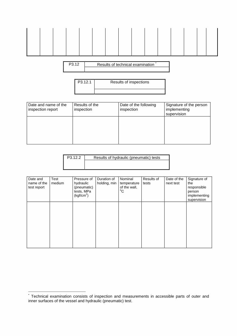
Date and name of the inspection report
Results of the inspection
Date of the following inspection
Signature of the person implementing supervision
Date and name of the test report
Test medium
Pressure of hydraulic (pneumatic) tests, MPa (kgf/cm2)
Duration of holding, min
Nominal temperature of the wall, оС
Results of tests
Date of the next test
Signature of the responsible person implementing supervision
∗ Technical examination consists of inspection and measurements in accessible parts of outer and inner surfaces of the vessel and hydraulic (pneumatic) test.
P3.12 Results of technical examination ∗
P3.12.1 Results of inspections
P3.12.2 Results of hydraulic (pneumatic) tests
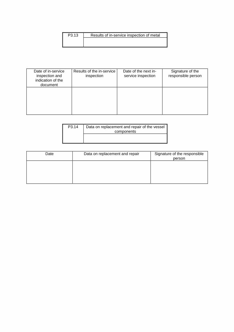
Date of in-service inspection and indication of the
document
Results of the in-service inspection
Date of the next in-service inspection
Signature of the responsible person
Date Data on replacement and repair Signature of the responsible person
P3.13 Results of in-service inspection of metal
P3.14 Data on replacement and repair of the vessel components
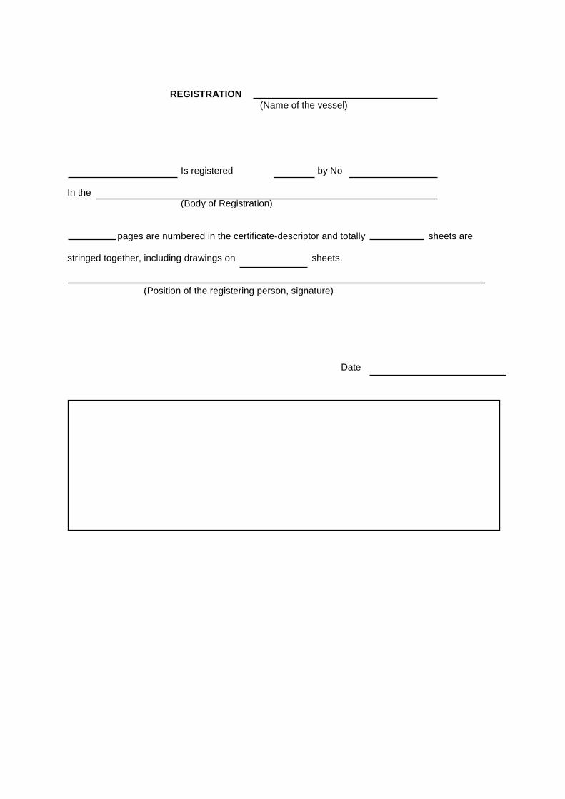
REGISTRATION (Name of the vessel) Is registered by No In the (Body of Registration) pages are numbered in the certificate-descriptor and totally sheets are stringed together, including drawings on sheets. (Position of the registering person, signature) Date
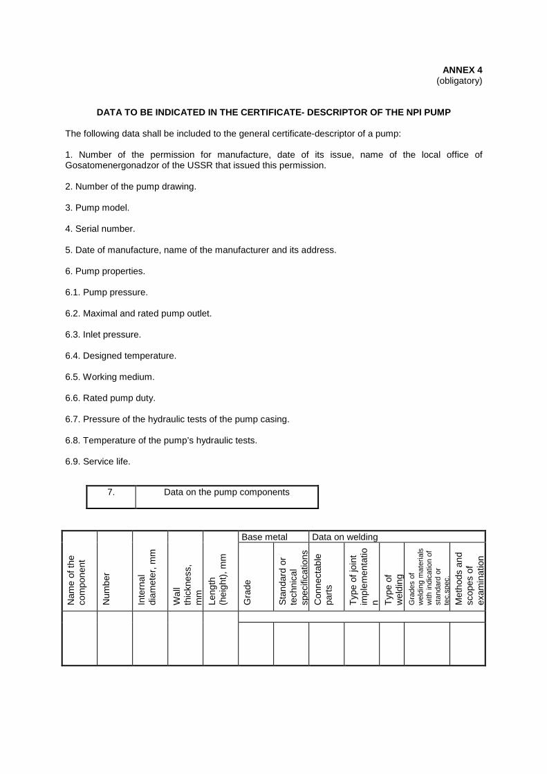
ANNEX 4 (obligatory)
DATA TO BE INDICATED IN THE CERTIFICATE- DESCRIPTOR OF THE NPI PUMP The following data shall be included to the general certificate-descriptor of a pump: 1. Number of the permission for manufacture, date of its issue, name of the local office of Gosatomenergonadzor of the USSR that issued this permission. 2. Number of the pump drawing. 3. Pump model. 4. Serial number. 5. Date of manufacture, name of the manufacturer and its address. 6. Pump properties. 6.1. Pump pressure. 6.2. Maximal and rated pump outlet. 6.3. Inlet pressure. 6.4. Designed temperature. 6.5. Working medium. 6.6. Rated pump duty. 6.7. Pressure of the hydraulic tests of the pump casing. 6.8. Temperature of the pump’s hydraulic tests. 6.9. Service life.
Base metal Data on welding
Nam
e of
the
com
pone
nt
Num
ber
Inte
rnal
di
amet
er, m
m
Wal
l th
ickn
ess,
m
m
Leng
th
(hei
ght)
, mm
G
rade
S
tand
ard
or
tech
nica
l sp
ecifi
catio
ns
Con
nect
able
pa
rts
Typ
e of
join
t im
plem
enta
tion T
ype
of
wel
ding
G
rade
s of
w
eldi
ng m
ater
ials
w
ith in
dica
tion
of
stan
dard
or
tec.
spec
.
Met
hods
and
sc
opes
of
exam
inat
ion
7. Data on the pump components
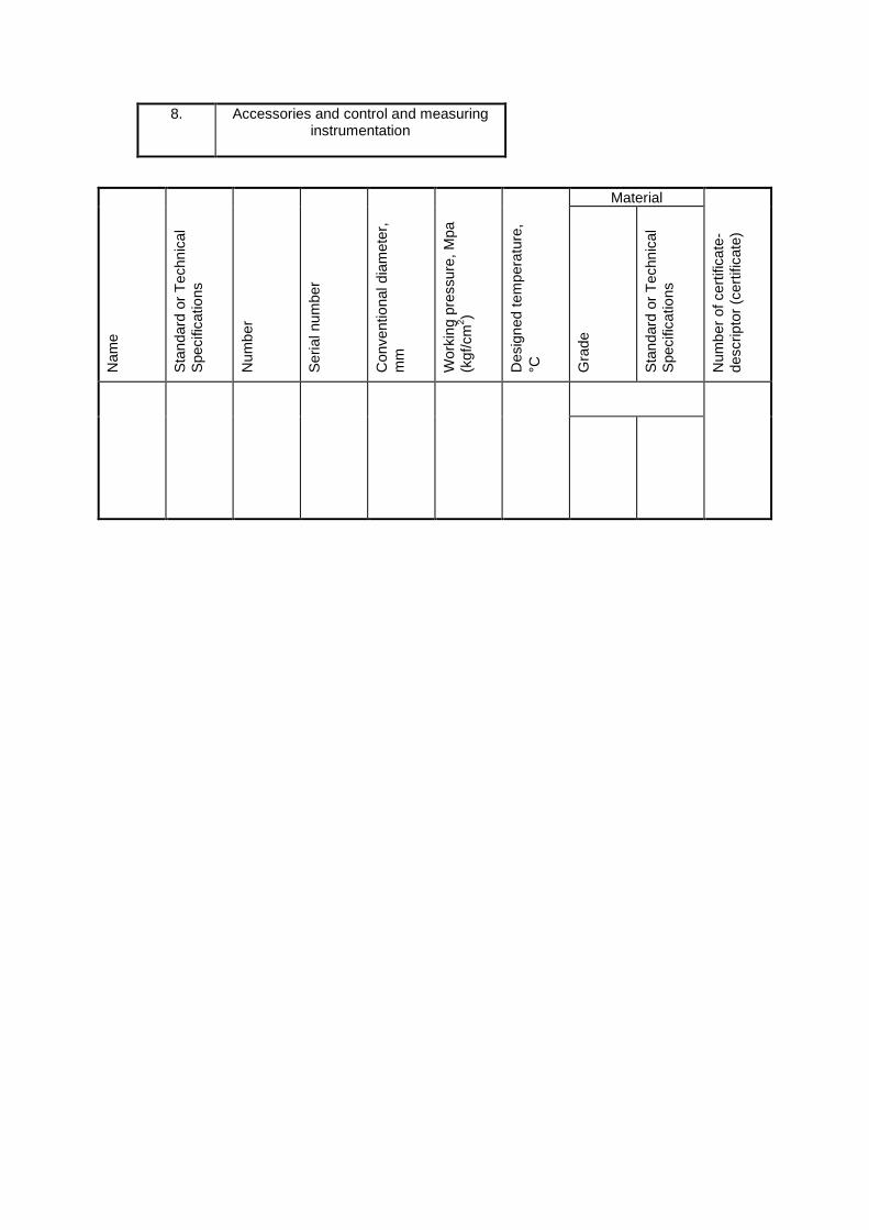
Material
Nam
e
Sta
ndar
d or
Tec
hnic
al
Spe
cific
atio
ns
Num
ber
Ser
ial n
umbe
r
Con
vent
iona
l dia
met
er,
mm
Wor
king
pre
ssur
e, M
pa
(kgf
/cm
2 )
Des
igne
d te
mpe
ratu
re,
°C
Gra
de
Sta
ndar
d or
Tec
hnic
al
Spe
cific
atio
ns
Num
ber
of c
ertif
icat
e-de
scrip
tor
(cer
tific
ate)
8. Accessories and control and measuring instrumentation
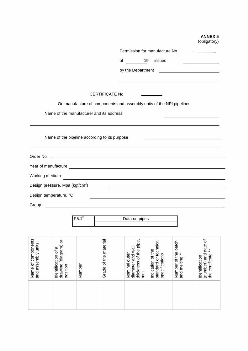
ANNEX 5
(obligatory) Permission for manufacture No of 19 issued by the Department CERTIFICATE No
On manufacture of components and assembly units of the NPI pipelines Name of the manufacturer and its address Name of the pipeline according to its purpose Order No Year of manufacture Working medium Design pressure, Mpa (kgf/cm2) Design temperature, °C Group
Nam
e of
com
pone
nts
and
asse
mbl
y un
its
Iden
tific
atio
n of
a
draw
ing
(dia
gram
) or
po
sitio
n
Num
ber
Gra
de o
f the
mat
eria
l
Nom
inal
out
er
diam
eter
and
wal
l th
ickn
ess
of th
e pi
pe,
mm
In
dica
tion
of th
e st
anda
rd o
r te
chni
cal
spec
ifica
tions
Num
ber
of th
e ba
tch
and
mel
ting
**
Iden
tific
atio
n (n
umbe
r) a
nd d
ate
of
the
cert
ifica
te *
*
P5.1х Data on pipes
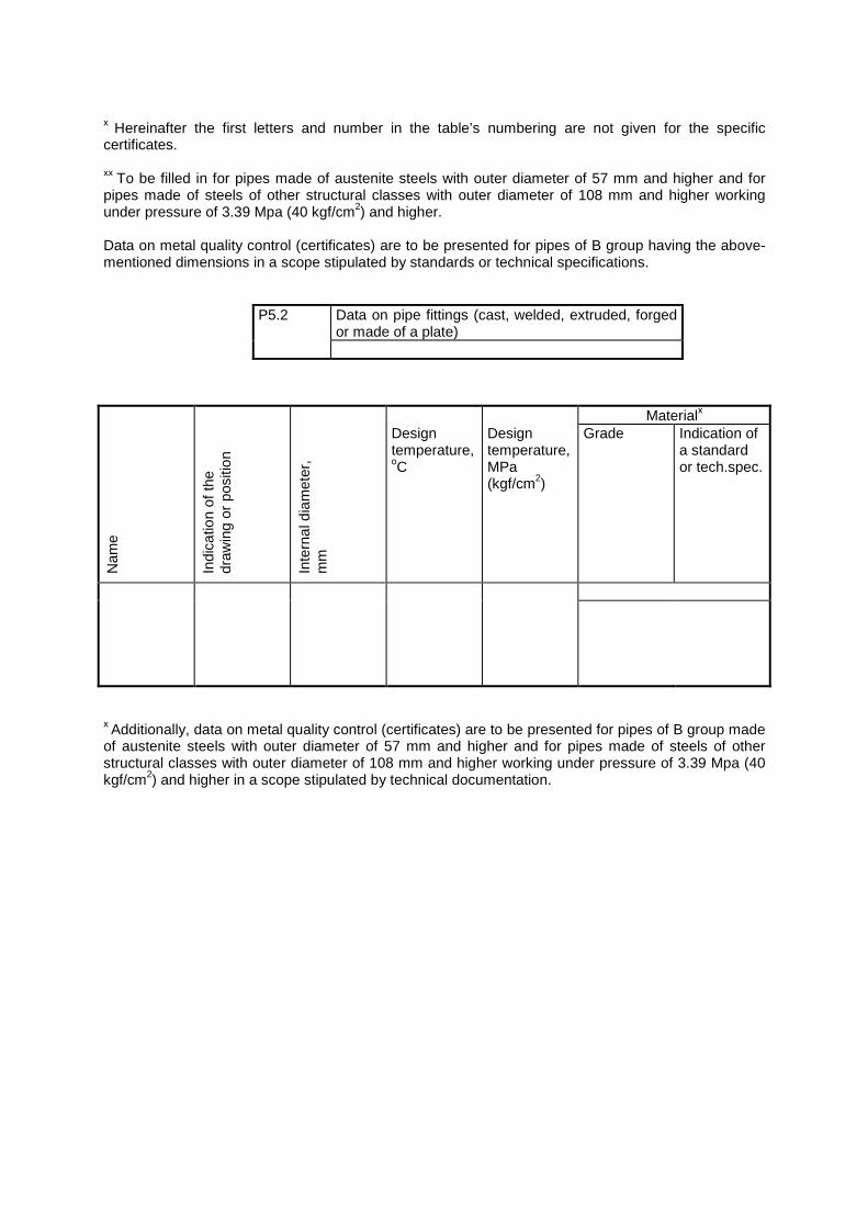
х Hereinafter the first letters and number in the table’s numbering are not given for the specific certificates. хх To be filled in for pipes made of austenite steels with outer diameter of 57 mm and higher and for pipes made of steels of other structural classes with outer diameter of 108 mm and higher working under pressure of 3.39 Mpa (40 kgf/cm2) and higher. Data on metal quality control (certificates) are to be presented for pipes of B group having the above-mentioned dimensions in a scope stipulated by standards or technical specifications. Materialх
Nam
e
Indi
catio
n of
the
draw
ing
or p
ositi
on
Inte
rnal
dia
met
er,
mm
Design temperature, оC
Design temperature, MPa (kgf/cm2)
Grade Indication of a standard or tech.spec.
х Additionally, data on metal quality control (certificates) are to be presented for pipes of B group made of austenite steels with outer diameter of 57 mm and higher and for pipes made of steels of other structural classes with outer diameter of 108 mm and higher working under pressure of 3.39 Mpa (40 kgf/cm2) and higher in a scope stipulated by technical documentation.
P5.2 Data on pipe fittings (cast, welded, extruded, forged or made of a plate)
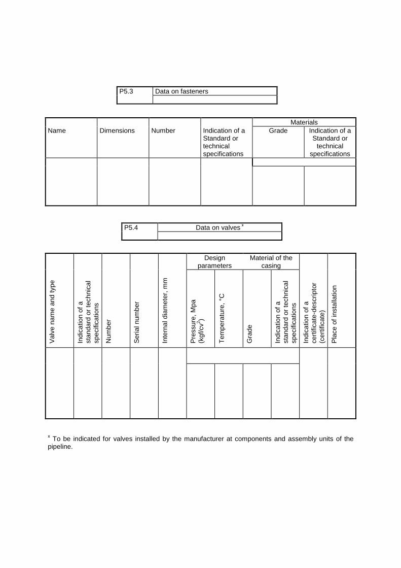
Materials Name Dimensions Number Indication of a
Standard or technical specifications
Grade Indication of a Standard or
technical specifications
Design
parameters Material of the
casing
Val
ve n
ame
and
type
Indi
catio
n of
a
stan
dard
or
tech
nica
l sp
ecifi
catio
ns
Num
ber
Ser
ial n
umbe
r
Inte
rnal
dia
met
er, m
m
Pre
ssur
e, M
pa
(kgf
/cv2 )
Tem
pera
ture
, °C
Gra
de
Indi
catio
n of
a
stan
dard
or
tech
nica
l sp
ecifi
catio
ns
Indi
catio
n of
a
cert
ifica
te-d
escr
ipto
r (c
ertif
icat
e)
Pla
ce o
f ins
talla
tion
х To be indicated for valves installed by the manufacturer at components and assembly units of the pipeline.
P5.3 Data on fasteners
P5.4 Data on valves х
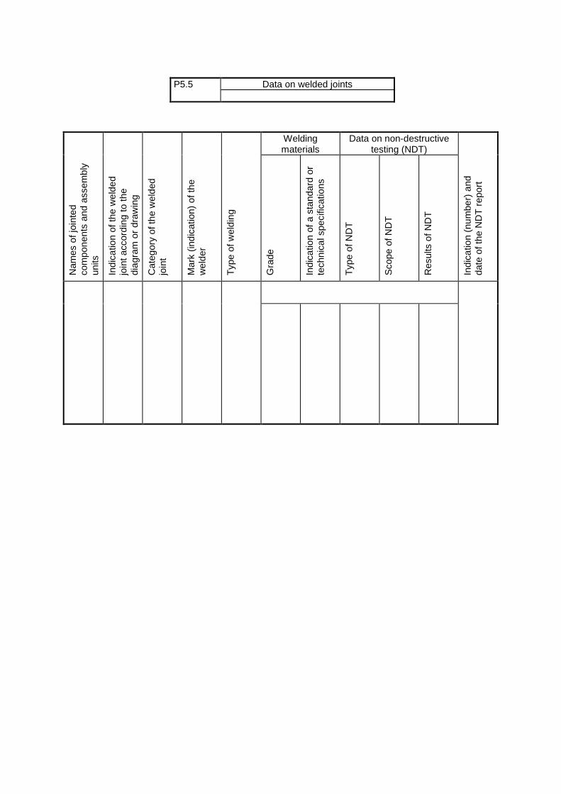
Welding
materials Data on non-destructive
testing (NDT)
Nam
es o
f joi
nted
co
mpo
nent
s an
d as
sem
bly
units
In
dica
tion
of th
e w
elde
d jo
int a
ccor
ding
to th
e di
agra
m o
r dr
awin
g
Cat
egor
y of
the
wel
ded
join
t
Mar
k (in
dica
tion)
of t
he
wel
der
Typ
e of
wel
ding
Gra
de
Indi
catio
n of
a s
tand
ard
or
tech
nica
l spe
cific
atio
ns
Typ
e of
ND
T
Sco
pe o
f ND
T
Res
ults
of N
DT
Indi
catio
n (n
umbe
r) a
nd
date
of t
he N
DT
rep
ort
P5.5 Data on welded joints
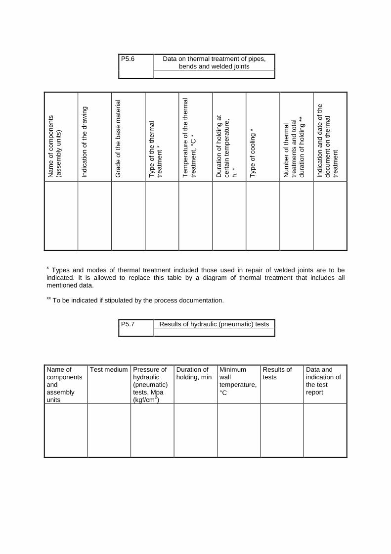
Nam
e of
com
pone
nts
(ass
embl
y un
its)
Indi
catio
n of
the
draw
ing
Gra
de o
f the
bas
e m
ater
ial
Typ
e of
the
ther
mal
tr
eatm
ent *
Tem
pera
ture
of t
he th
erm
al
trea
tmen
t, °C
*
Dur
atio
n of
hol
ding
at
cert
ain
tem
pera
ture
, h.
*
Typ
e of
coo
ling
*
Num
ber
of th
erm
al
trea
tmen
ts a
nd to
tal
dura
tion
of h
oldi
ng *
*
Indi
catio
n an
d da
te o
f the
do
cum
ent o
n th
erm
al
trea
tmen
t
х Types and modes of thermal treatment included those used in repair of welded joints are to be indicated. It is allowed to replace this table by a diagram of thermal treatment that includes all mentioned data. хх To be indicated if stipulated by the process documentation. Name of components and assembly units
Test medium Pressure of hydraulic (pneumatic) tests, Mpa (kgf/cm2)
Duration of holding, min
Minimum wall temperature, °C
Results of tests
Data and indication of the test report
P5.6 Data on thermal treatment of pipes, bends and welded joints
P5.7 Results of hydraulic (pneumatic) tests
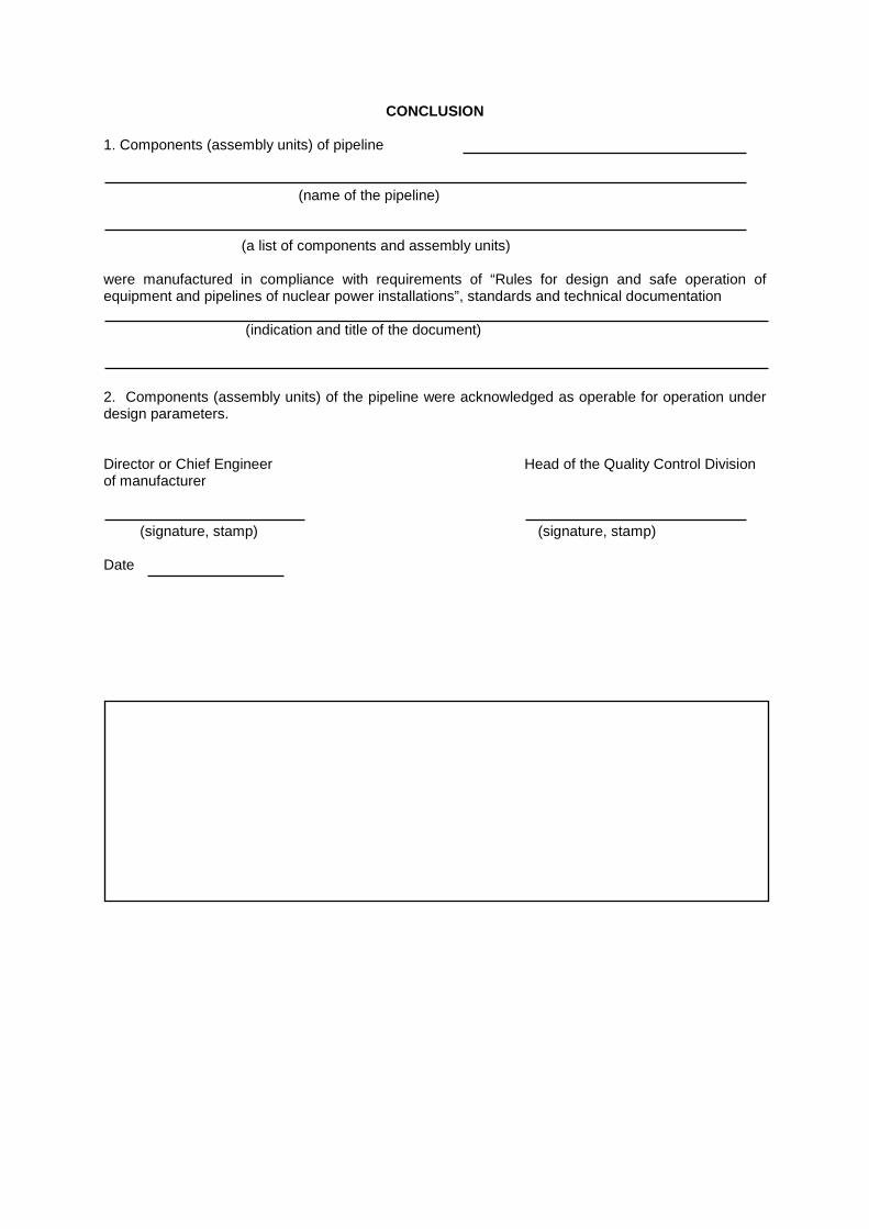
CONCLUSION 1. Components (assembly units) of pipeline (name of the pipeline) (a list of components and assembly units) were manufactured in compliance with requirements of “Rules for design and safe operation of equipment and pipelines of nuclear power installations”, standards and technical documentation (indication and title of the document) 2. Components (assembly units) of the pipeline were acknowledged as operable for operation under design parameters. Director or Chief Engineer Head of the Quality Control Division of manufacturer (signature, stamp) (signature, stamp) Date
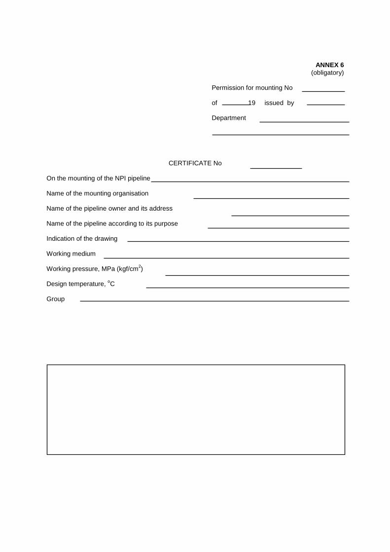
ANNEX 6 (obligatory)
Permission for mounting No of 19 issued by Department
CERTIFICATE No On the mounting of the NPI pipeline Name of the mounting organisation Name of the pipeline owner and its address Name of the pipeline according to its purpose Indication of the drawing Working medium Working pressure, MPa (kgf/cm2) Design temperature, оC Group
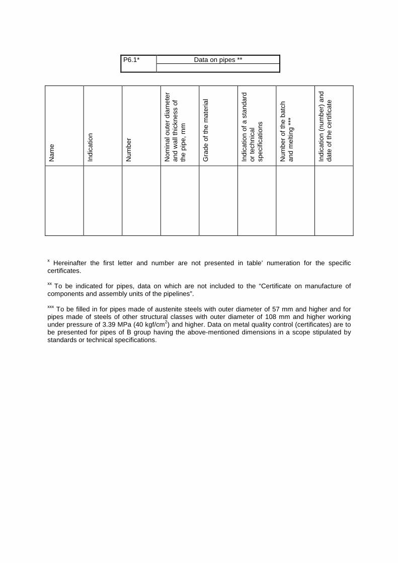
Nam
e
Indi
catio
n
Num
ber
Nom
inal
out
er d
iam
eter
an
d w
all t
hick
ness
of
the
pipe
, mm
G
rade
of t
he m
ater
ial
Indi
catio
n of
a s
tand
ard
or te
chni
cal
spec
ifica
tions
Num
ber
of th
e ba
tch
and
mel
ting
***
Indi
catio
n (n
umbe
r) a
nd
date
of t
he c
ertif
icat
e
х Hereinafter the first letter and number are not presented in table’ numeration for the specific certificates. хх To be indicated for pipes, data on which are not included to the “Certificate on manufacture of components and assembly units of the pipelines”. ххх To be filled in for pipes made of austenite steels with outer diameter of 57 mm and higher and for pipes made of steels of other structural classes with outer diameter of 108 mm and higher working under pressure of 3.39 MPa (40 kgf/cm2) and higher. Data on metal quality control (certificates) are to be presented for pipes of B group having the above-mentioned dimensions in a scope stipulated by standards or technical specifications.
P6.1* Data on pipes **
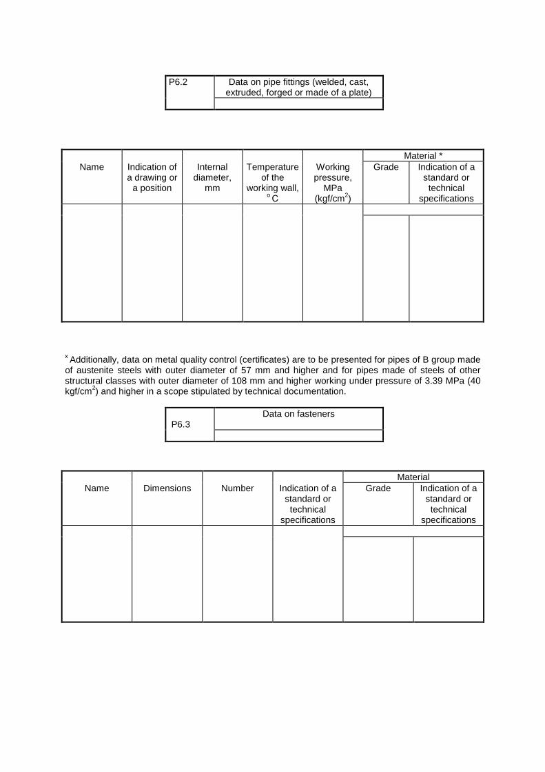
Material *
Name Indication of a drawing or
a position
Internal diameter,
mm
Temperature of the
working wall, о С
Working pressure,
MPa (kgf/cm2)
Grade Indication of a standard or
technical specifications
х Additionally, data on metal quality control (certificates) are to be presented for pipes of B group made of austenite steels with outer diameter of 57 mm and higher and for pipes made of steels of other structural classes with outer diameter of 108 mm and higher working under pressure of 3.39 MPa (40 kgf/cm2) and higher in a scope stipulated by technical documentation. Material
Name Dimensions Number Indication of a standard or technical
specifications
Grade Indication of a standard or technical
specifications
P6.2 Data on pipe fittings (welded, cast, extruded, forged or made of a plate)
P6.3
Data on fasteners
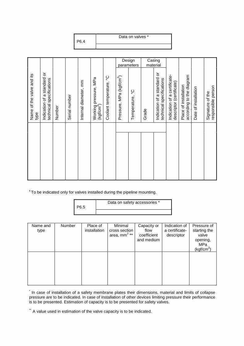
Design
parameters Casing material
Nam
e of
the
valv
e an
d its
ty
pe
Indi
catio
n of
a s
tand
ard
or
tech
nica
l spe
cific
atio
ns
Num
ber
Ser
ial n
umbe
r
Inte
rnal
dia
met
er, m
m
Wor
king
pre
ssur
e, M
Pa
(kgf
/cm
2 )
Coo
lant
tem
pera
ture
, °C
Pre
ssur
e, M
Pa
(kgf
/cm
2 )
Tem
pera
ture
, °C
Gra
de
Indi
catio
n of
a s
tand
ard
or
tech
nica
l spe
cific
atio
ns
Indi
catio
n of
a c
ertif
icat
e-de
scrip
tor
(cer
tific
ate)
P
lace
of i
nsta
llatio
n ac
cord
ing
to th
e di
agra
m
(dra
win
g)
Dat
e of
inst
alla
tion
Sig
natu
re o
f the
re
spon
sibl
e pe
rson
х To be indicated only for valves installed during the pipeline mounting.
Name and type
Number Place of installation
Minimal cross section area, mm2 **
Capacity or flow
coefficient and medium
Indication of a certificate-descriptor
Pressure of starting the
valve opening,
MPa (kgf/cm2)
* In case of installation of a safety membrane plates their dimensions, material and limits of collapse pressure are to be indicated. In case of installation of other devices limiting pressure their performance is to be presented. Estimation of capacity is to be presented for safety valves. ** A value used in estimation of the valve capacity is to be indicated.
P6.4
Data on valves *
P6.5
Data on safety accessories *
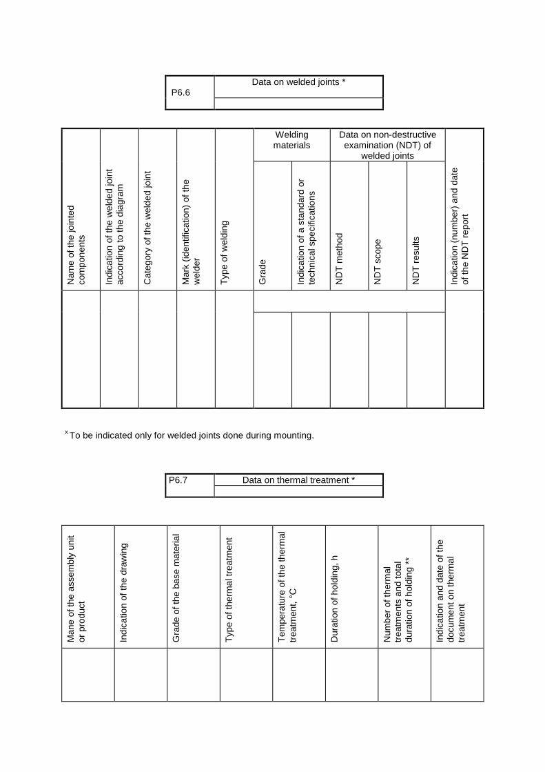
Welding
materials Data on non-destructive examination (NDT) of
welded joints
Nam
e of
the
join
ted
com
pone
nts
Indi
catio
n of
the
wel
ded
join
t ac
cord
ing
to th
e di
agra
m
Cat
egor
y of
the
wel
ded
join
t
Mar
k (id
entif
icat
ion)
of t
he
wel
der
Typ
e of
wel
ding
Gra
de
Indi
catio
n of
a s
tand
ard
or
tech
nica
l spe
cific
atio
ns
ND
T m
etho
d
ND
T s
cope
ND
T r
esul
ts
Indi
catio
n (n
umbe
r) a
nd d
ate
of th
e N
DT
rep
ort
х To be indicated only for welded joints done during mounting.
Man
e of
the
asse
mbl
y un
it or
pro
duct
Indi
catio
n of
the
draw
ing
Gra
de o
f the
bas
e m
ater
ial
Typ
e of
ther
mal
trea
tmen
t
Tem
pera
ture
of t
he th
erm
al
trea
tmen
t, °C
Dur
atio
n of
hol
ding
, h
Num
ber
of th
erm
al
trea
tmen
ts a
nd to
tal
dura
tion
of h
oldi
ng *
* In
dica
tion
and
date
of t
he
docu
men
t on
ther
mal
tr
eatm
ent
P6.6
Data on welded joints *
P6.7 Data on thermal treatment *
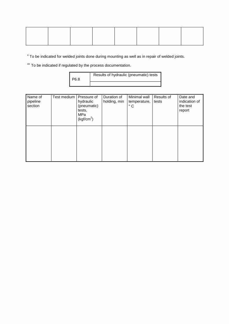
х To be indicated for welded joints done during mounting as well as in repair of welded joints. хх To be indicated if regulated by the process documentation. Name of pipeline section
Test medium Pressure of hydraulic (pneumatic) tests, MPa (kgf/cm2)
Duration of holding, min
Minimal wall temperature, ° C
Results of tests
Date and indication of the test report
P6.8
Results of hydraulic (pneumatic) tests
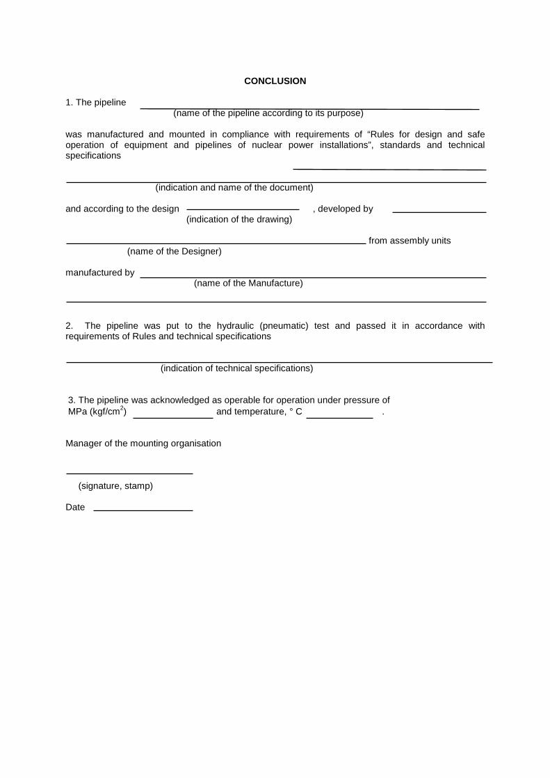
CONCLUSION
1. The pipeline (name of the pipeline according to its purpose) was manufactured and mounted in compliance with requirements of “Rules for design and safe operation of equipment and pipelines of nuclear power installations”, standards and technical specifications (indication and name of the document) and according to the design , developed by (indication of the drawing) from assembly units (name of the Designer) manufactured by (name of the Manufacture) 2. The pipeline was put to the hydraulic (pneumatic) test and passed it in accordance with requirements of Rules and technical specifications (indication of technical specifications) 3. The pipeline was acknowledged as operable for operation under pressure of MPa (kgf/cm2) and temperature, ° C . Manager of the mounting organisation (signature, stamp) Date

ANNEX 7 (obligatory)
Permission for mounting No of 19 issued by Department CERTIFICATE No
On mounting (remanufacture) of the vessel
Name of the mounting organisation (manufacture) Name of the owner and its address Name (purpose) of the vessel Serial number Year of manufacture Indication of the drawing Working medium Working pressure, MPa (kgf/cm2) Design temperature, о
С Group of equipment
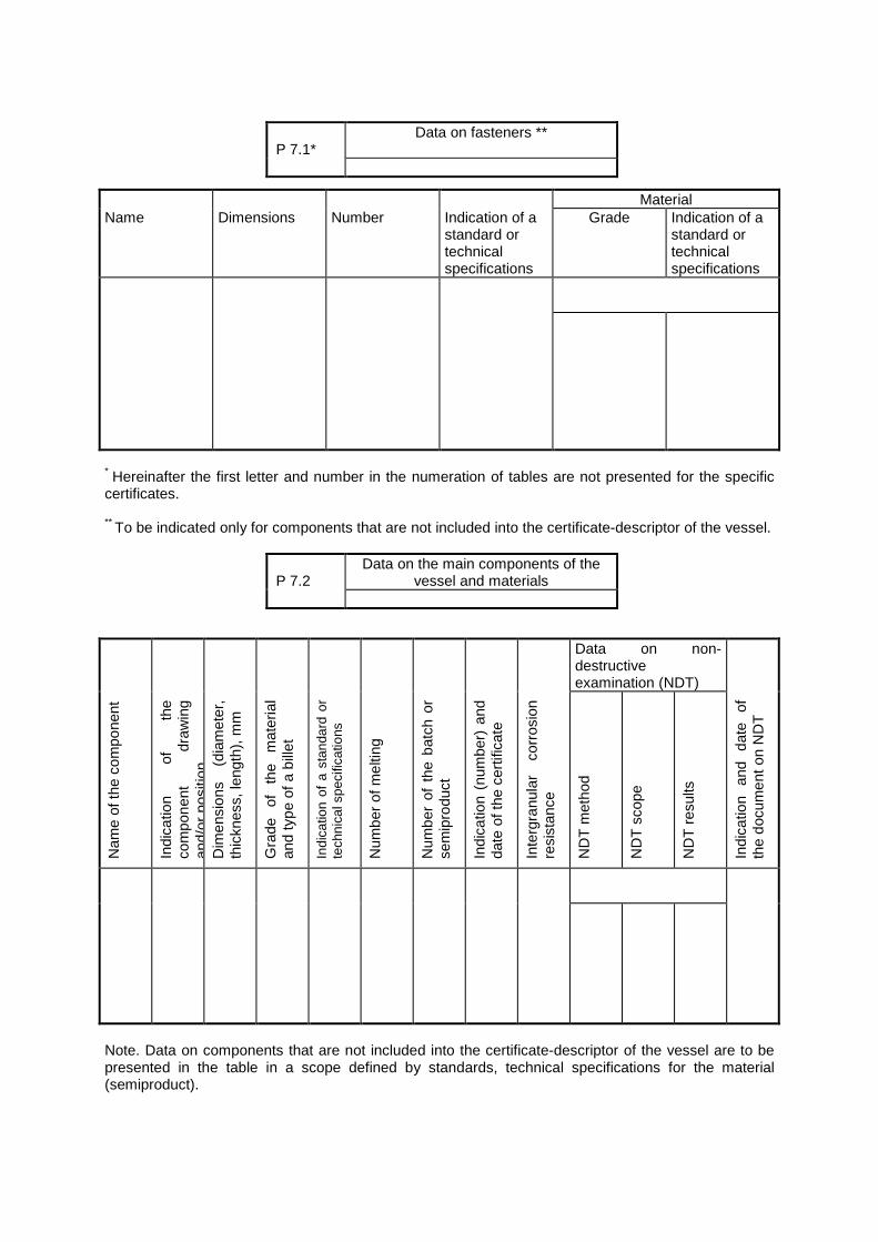
Material Name Dimensions Number Indication of a
standard or technical specifications
Grade Indication of a standard or technical specifications
* Hereinafter the first letter and number in the numeration of tables are not presented for the specific certificates. ** To be indicated only for components that are not included into the certificate-descriptor of the vessel. Data on non-
destructive examination (NDT)
Nam
e of
the
com
pone
nt
Indi
catio
n of
th
e co
mpo
nent
dr
awin
g an
d/or
pos
ition
D
imen
sion
s (d
iam
eter
, th
ickn
ess,
leng
th),
mm
Gra
de
of
the
mat
eria
l an
d ty
pe o
f a b
illet
Indi
catio
n of
a s
tand
ard
or
tech
nica
l spe
cific
atio
ns
Num
ber
of m
eltin
g
Num
ber
of t
he b
atch
or
sem
ipro
duct
Indi
catio
n (n
umbe
r) a
nd
date
of t
he c
ertif
icat
e
Inte
rgra
nula
r co
rros
ion
resi
stan
ce
ND
T m
etho
d
ND
T s
cope
ND
T r
esul
ts
Indi
catio
n an
d da
te
of
the
docu
men
t on
ND
T
Note. Data on components that are not included into the certificate-descriptor of the vessel are to be presented in the table in a scope defined by standards, technical specifications for the material (semiproduct).
P 7.1*
Data on fasteners **
P 7.2
Data on the main components of the vessel and materials
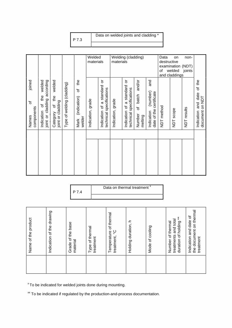
Welded
materials Welding (cladding) materials
Data on non-destructive examination (NDT) of welded joints and claddings
Nam
es
of
join
ed
com
pone
nts
Indi
catio
n of
th
e w
elde
d jo
int
or c
ladd
ing
acco
rdin
g to
the
diag
ram
C
ateg
ory
of
the
wel
ded
join
t or
clad
ding
Typ
e of
wel
ding
(cl
addi
ng)
Mar
k (in
dica
tion)
of
th
e w
elde
r
Indi
catio
n, g
rade
Indi
catio
n of
a s
tand
ard
or
tech
nica
l spe
cific
atio
ns
Indi
catio
n, g
rade
Indi
catio
n of
a s
tand
ard
or
tech
nica
l spe
cific
atio
ns
Num
ber
of
batc
h an
d/or
m
eltin
g
Indi
catio
n (n
umbe
r)
and
date
of t
he c
ertif
icat
e
ND
T m
etho
d
ND
T s
cope
ND
T r
esul
ts
Indi
catio
n an
d da
te o
f th
e do
cum
ent o
n N
DT
Nam
e of
the
prod
uct
Indi
catio
n of
the
draw
ing
Gra
de o
f the
bas
e m
ater
ial
Typ
e of
ther
mal
tr
eatm
ent
Tem
pera
ture
of t
herm
al
trea
tmen
t, °C
Hol
ding
dur
atio
n, h
Mod
e of
coo
ling
Num
ber
of th
erm
al
trea
tmen
ts a
nd to
tal
dura
tion
of h
oldi
ng *
* In
dica
tion
and
date
of
the
docu
men
t on
ther
mal
tr
eatm
ent
х To be indicated for welded joints done during mounting. хх To be indicated if regulated by the production-and-process documentation.
P 7.3
Data on welded joints and cladding *
P 7.4
Data on thermal treatment х
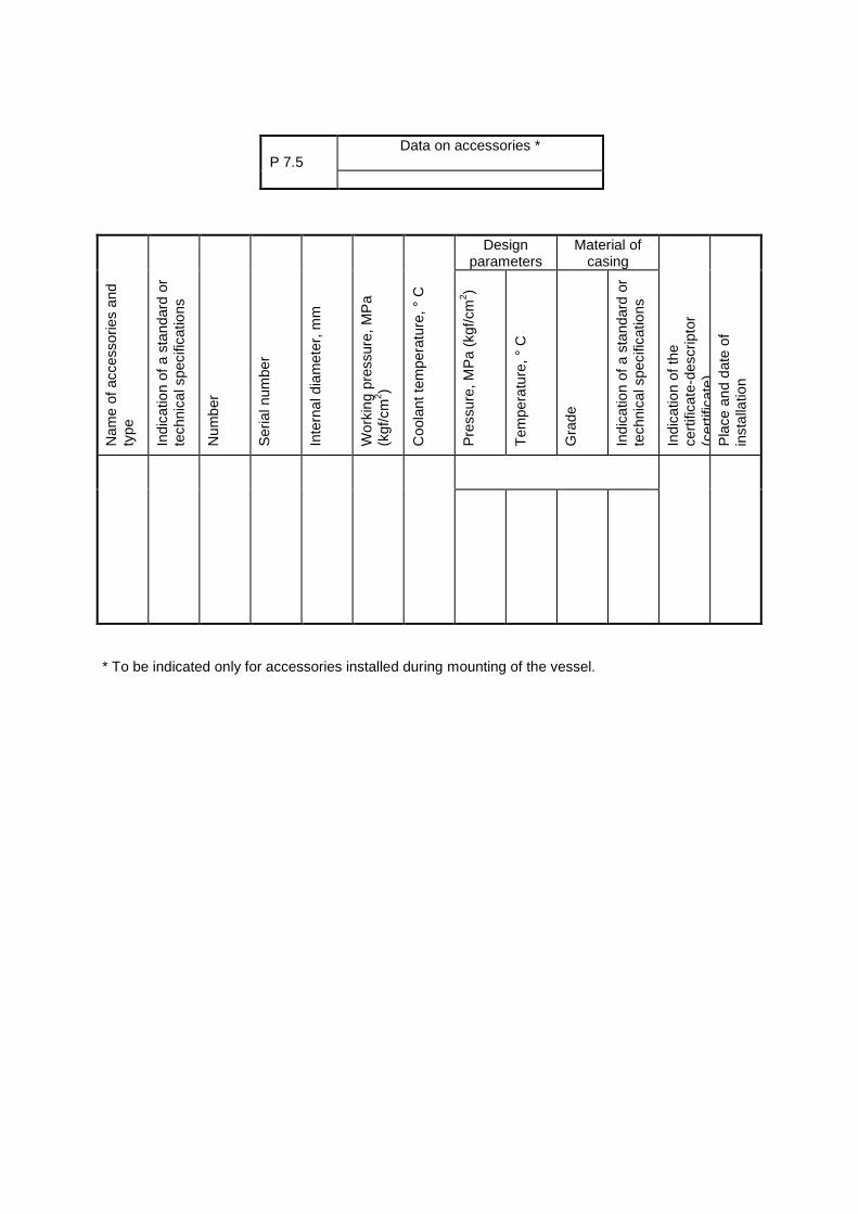
Design
parameters Material of
casing
Nam
e of
acc
esso
ries
and
type
In
dica
tion
of a
sta
ndar
d or
te
chni
cal s
peci
ficat
ions
Num
ber
Ser
ial n
umbe
r
Inte
rnal
dia
met
er, m
m
Wor
king
pre
ssur
e, M
Pa
(kgf
/cm
2 )
Coo
lant
tem
pera
ture
, ° C
Pre
ssur
e, M
Pa
(kgf
/cm
2 )
Tem
pera
ture
, ° C
Gra
de
Indi
catio
n of
a s
tand
ard
or
tech
nica
l spe
cific
atio
ns
Indi
catio
n of
the
cert
ifica
te-d
escr
ipto
r (c
ertif
icat
e)
Pla
ce a
nd d
ate
of
inst
alla
tion
* To be indicated only for accessories installed during mounting of the vessel.
P 7.5
Data on accessories *
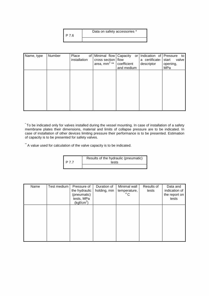
Name, type Number Place of
installation Minimal flow cross section area, mm2 **
Capacity or flow coefficient and medium
Indication of a certificate-descriptor
Pressure to start valve opening, MPa
* To be indicated only for valves installed during the vessel mounting. In case of installation of a safety membrane plates their dimensions, material and limits of collapse pressure are to be indicated. In case of installation of other devices limiting pressure their performance is to be presented. Estimation of capacity is to be presented for safety valves. ** A value used for calculation of the valve capacity is to be indicated.
Name Test medium Pressure of the hydraulic (pneumatic) tests, MPa (kgf/cm2)
Duration of holding, min
Minimal wall temperature,
о C
Results of tests
Data and indication of the report on
tests
P 7.6
Data on safety accessories *
P 7.7
Results of the hydraulic (pneumatic) tests
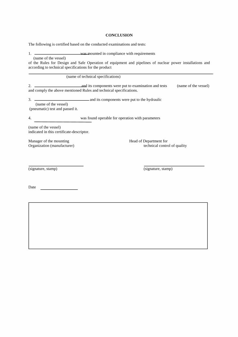
CONCLUSION
The following is certified based on the conducted examinations and tests: 1. was mounted in compliance with requirements (name of the vessel) of the Rules for Design and Safe Operation of equipment and pipelines of nuclear power installations and according to technical specifications for the product (name of technical specifications) 2. and its components were put to examination and tests (name of the vessel) and comply the above mentioned Rules and technical specifications. 3. and its components were put to the hydraulic
(name of the vessel) (pneumatic) test and passed it. 4. was found operable for operation with parameters (name of the vessel) indicated in this certificate-descriptor. Manager of the mounting Head of Department for Organization (manufacturer) technical control of quality (signature, stamp) (signature, stamp) Date
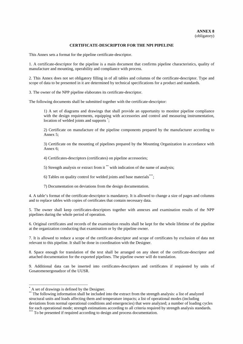
ANNEX 8 (obligatory)
CERTIFICATE-DESCRIPTOR FOR THE NPI PIPELINE
This Annex sets a format for the pipeline certificate-descriptor. 1. A certificate-descriptor for the pipeline is a main document that confirms pipeline characteristics, quality of manufacture and mounting, operability and compliance with process. 2. This Annex does not set obligatory filling in of all tables and columns of the certificate-descriptor. Type and scope of data to be presented in it are determined by technical specifications for a product and standards. 3. The owner of the NPP pipeline elaborates its certificate-descriptor. The following documents shall be submitted together with the certificate-descriptor:
1) A set of diagrams and drawings that shall provide an opportunity to monitor pipeline compliance with the design requirements, equipping with accessories and control and measuring instrumentation, location of welded joints and supports *; 2) Certificate on manufacture of the pipeline components prepared by the manufacturer according to Annex 5; 3) Certificate on the mounting of pipelines prepared by the Mounting Organization in accordance with Annex 6; 4) Certificates-descriptors (certificates) on pipeline accessories; 5) Strength analysis or extract from it ** with indication of the name of analysis; 6) Tables on quality control for welded joints and base materials*** ; 7) Documentation on deviations from the design documentation.
4. A table’s format of the certificate-descriptor is mandatory. It is allowed to change a size of pages and columns and to replace tables with copies of certificates that contain necessary data. 5. The owner shall keep certificates-descriptors together with annexes and examination results of the NPP pipelines during the whole period of operation. 6. Original certificates and records of the examination results shall be kept for the whole lifetime of the pipeline at the organization conducting that examination or by the pipeline owner. 7. It is allowed to reduce a scope of the certificate-descriptor and scope of certificates by exclusion of data not relevant to this pipeline. It shall be done in coordination with the Designer. 8. Space enough for translation of the text shall be arranged on any sheet of the certificate-descriptor and attached documentation for the exported pipelines. The pipeline owner will do translation. 9. Additional data can be inserted into certificates-descriptors and certificates if requiested by units of Gosatomenergonadzor of the UUSR.
* A set of drawings is defined by the Designer. ** The following information shall be included into the extract from the strength analysis: a list of analyzed structural units and loads affecting them and temperature impacts; a list of operational modes (including deviations from normal operational conditions and emergencies) that were analyzed; a number of loading cycles for each operational mode; strength estimations according to all criteria required by strength analysis standards. *** To be presented if required according to design and process documentation.

CERTIFICATE-DESCRIPTER FOR THE PIPELINE .......................................... (Name) Registration number Note. The registration number is assigned by the local office of Gosgortechnadzor of the USSR (in case of registration at that office) or by the owner (in case of pipeline registration at that organization).
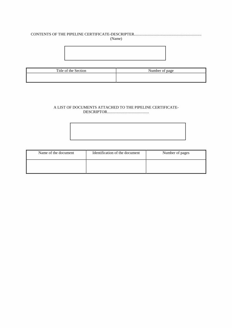
CONTENTS OF THE PIPELINE CERTIFICATE-DESCRIPTER.....................................................................
(Name)
Title of the Section Number of page
A LIST OF DOCUMENTS ATTACHED TO THE PIPELINE CERTIFICATE-DESCRIPTOR...........................................
Name of the document Identification of the document Number of pages
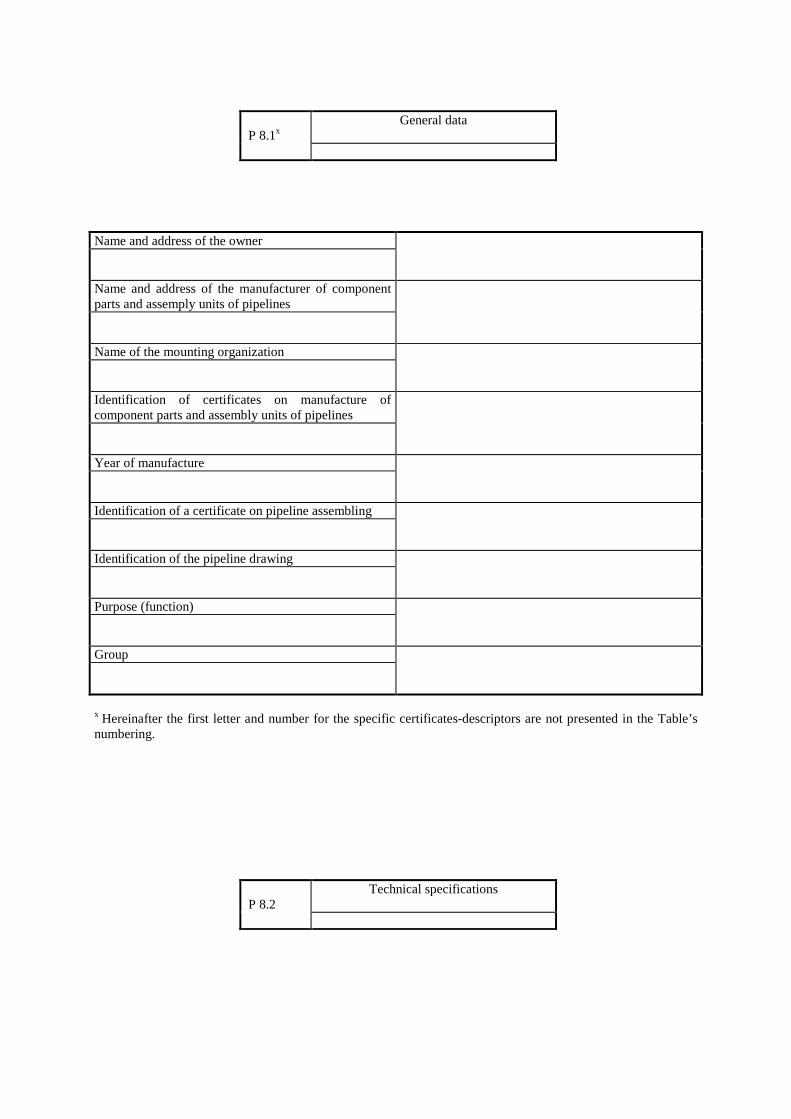
Name and address of the owner
Name and address of the manufacturer of component parts and assemply units of pipelines
Name of the mounting organization
Identification of certificates on manufacture of component parts and assembly units of pipelines
Year of manufacture
Identification of a certificate on pipeline assembling
Identification of the pipeline drawing
Purpose (function)
Group
х Hereinafter the first letter and number for the specific certificates-descriptors are not presented in the Table’s numbering.
P 8.1х
General data
P 8.2
Technical specifications
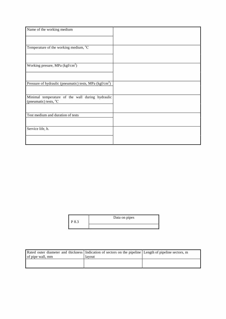
Name of the working medium
Temperature of the working medium, оС
Working presure, MPa (kgf/cm2)
Pressure of hydraulic (pneumatic) tests, MPa (kgf/cm2)
Minimal temperature of the wall during hydraulic (pneumatic) tests, оС
Test medium and duration of tests
Service life, h.
Rated outer diameter and thickness of pipe wall, mm
Indication of sectors on the pipeline layout
Length of pipeline sectors, m
P 8.3
Data on pipes
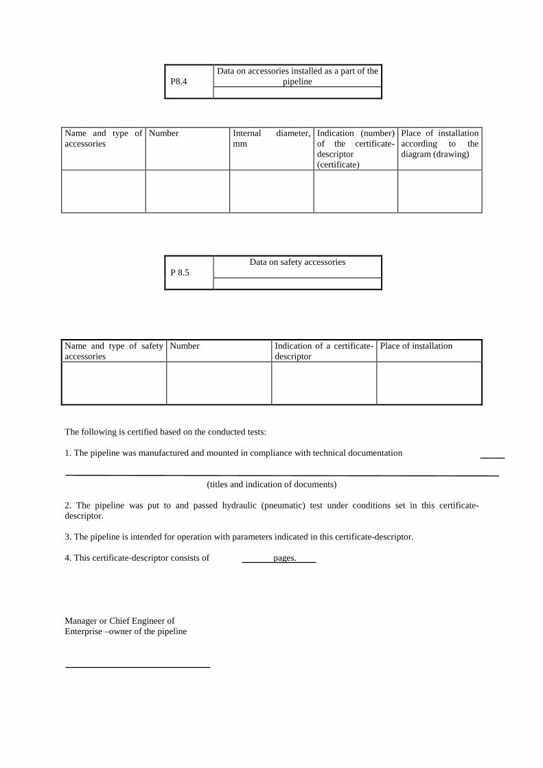
Name and type of accessories
Number Internal diameter, mm
Indication (number) of the certificate-descriptor (certificate)
Place of installation according to the diagram (drawing)
Name and type of safety accessories
Number Indication of a certificate-descriptor
Place of installation
The following is certified based on the conducted tests: 1. The pipeline was manufactured and mounted in compliance with technical documentation
(titles and indication of documents)
2. The pipeline was put to and passed hydraulic (pneumatic) test under conditions set in this certificate-descriptor. 3. The pipeline is intended for operation with parameters indicated in this certificate-descriptor. 4. This certificate-descriptor consists of pages. Manager or Chief Engineer of Enterprise –owner of the pipeline
P8.4
Data on accessories installed as a part of the pipeline
P 8.5
Data on safety accessories
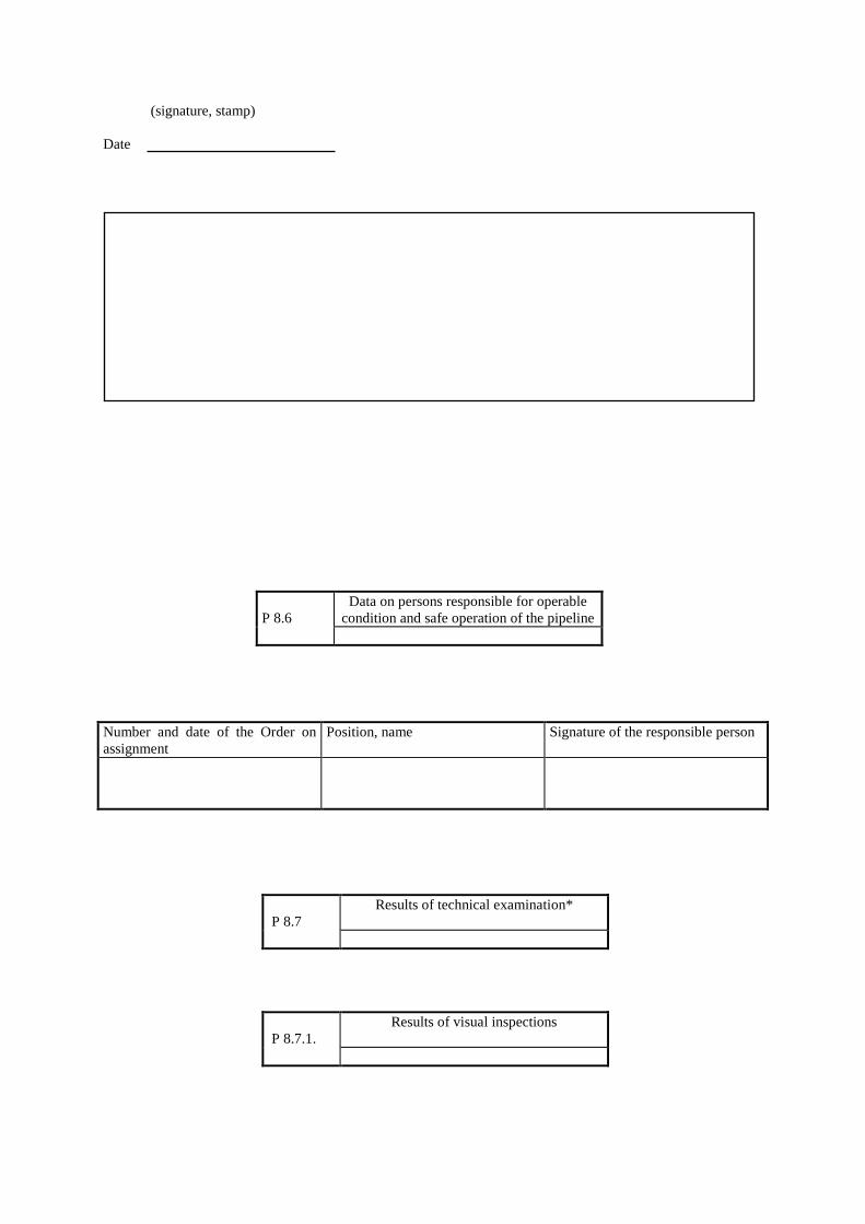
(signature, stamp) Date Number and date of the Order on assignment
Position, name Signature of the responsible person
P 8.6
Data on persons responsible for operable condition and safe operation of the pipeline
P 8.7
Results of technical examination*
P 8.7.1.
Results of visual inspections
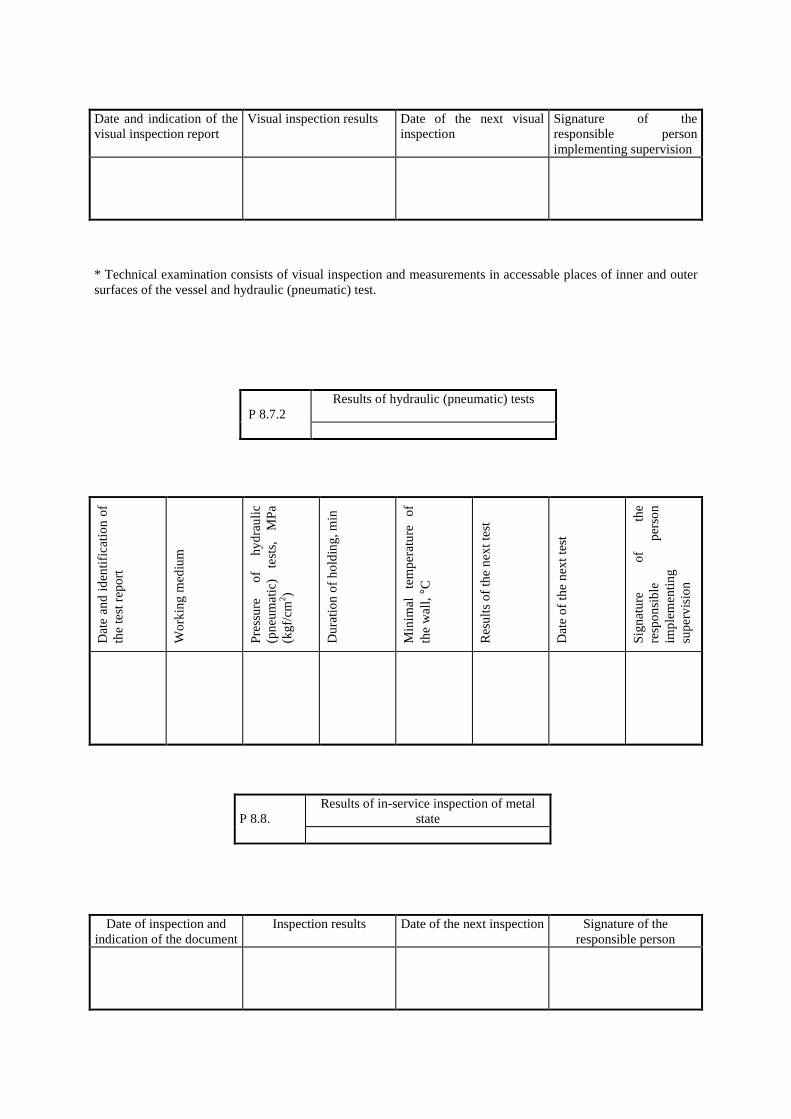
Date and indication of the visual inspection report
Visual inspection results Date of the next visual inspection
Signature of the responsible person implementing supervision
* Technical examination consists of visual inspection and measurements in accessable places of inner and outer surfaces of the vessel and hydraulic (pneumatic) test.
Dat
e an
d id
entif
icat
ion
of
the
test
rep
ort
Wo
rkin
g m
ediu
m
Pre
ssu
re
of
hyd
rau
lic
(pn
eum
atic
) te
sts,
M
Pa
(k
gf/
cm2 )
Du
ratio
n o
f ho
ldin
g, m
in
Min
imal
te
mp
erat
ure
o
f th
e w
all, °
C
Res
ults
of
the
nex
t tes
t
Dat
e o
f th
e n
ext t
est
Sig
nat
ure
of
th
e re
spo
nsi
ble
p
erso
n im
ple
men
ting
su
per
visi
on
Date of inspection and indication of the document
Inspection results Date of the next inspection Signature of the responsible person
P 8.7.2
Results of hydraulic (pneumatic) tests
P 8.8.
Results of in-service inspection of metal state
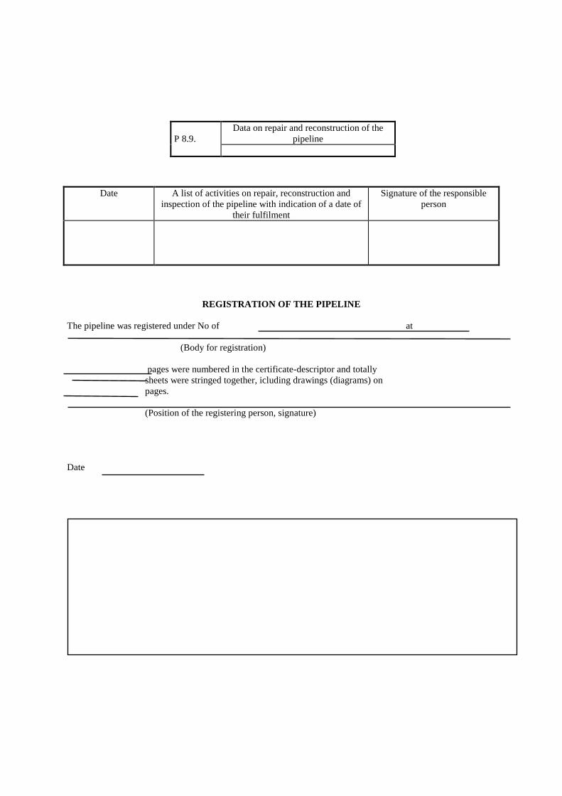
Date A list of activities on repair, reconstruction and inspection of the pipeline with indication of a date of
their fulfilment
Signature of the responsible person
REGISTRATION OF THE PIPELINE The pipeline was registered under No of at (Body for registration) pages were numbered in the certificate-descriptor and totally sheets were stringed together, icluding drawings (diagrams) on pages. (Position of the registering person, signature) Date
P 8.9.
Data on repair and reconstruction of the pipeline
ANNEX 9 (obligatory)
BASIC MATERIALS (SEMIPRODUCTS) PERMITTED FOR MANUFACTURE OF EQUIPMENT AND PIPELINES
Grades of materials which use is permitted, documentation (with mandatory requirements given in notes to the table) and limiting temperatures for the use of materials are listed in Table P9.1 of this Annex. Standards and technical specifications having references to the notes of the Table can be used only in case of compliance with requirements indicated in those notes. In coordination with the Leading Material Science Organization and Gosatomenergonadzor of the USSR the Designer can use other standards and technical specifications that are not mentioned in Table P9.1 for materials (semiproducts) delivery, which grades are presented in the Table. The only condition for that is that mechanical properties, scope of inspection and criteria used for estimation of parameters to be inspected according to that different standards and technical specifications ensure the same or higher quality of materials (semiproducts) than standards and technical specifications indicated in Table P9.1. The imported materials (semiproducts) shall be used according to provisions of these Rules (Section 3.4). Materials (semiproducts) shall be put to thermal treatment in accordance with instructions of standards and technical specifications for the delivery of materials and semiproducts.
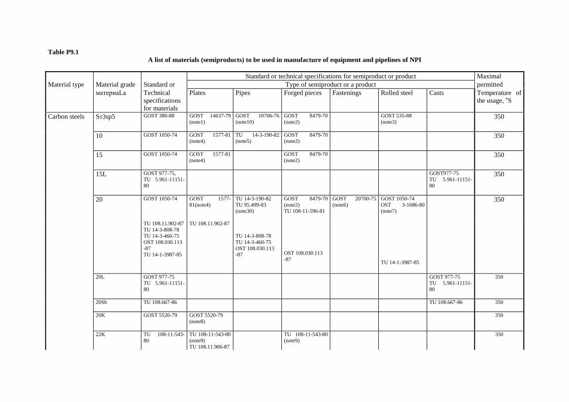
Table P9.1 A list of materials (semiproducts) to be used in manufacture of equipment and pipelines of NPI
Standard or technical specifications for semiproduct or product Maximal Material type Material grade Standard or Type of semiproduct or a product permitted материаLа Technical
specifications for materials
Plates Pipes Forged pieces Fastenings Rolled steel Casts Temperature of the usage, оS
Carbon steels Sт3sp5 GOST 380-88 GOST 14637-79 (note1)
GOST 10706-76 (note10)
GOST 8479-70 (note2)
GOST 535-88 (note3)
350
10 GOST 1050-74 GOST 1577-81 (note4)
TU 14-3-190-82 (note5)
GOST 8479-70 (note2)
350
15 GOST 1050-74 GOST 1577-81 (note4)
GOST 8479-70 (note2)
350
15L GOST 977-75, TU 5.961-11151-80
GOST977-75 TU 5.961-11151-80
350
20 GOST 1050-74 GOST 1577-81(note4)
TU 14-3-190-82 TU 95.499-83 (note30)
GOST 8479-70 (note2) TU 108-11-596-81
GOST 20700-75 (note6)
GOST 1050-74 OST 3-1686-80 (note7)
350
TU 108.11.902-87 TU 14-3-808-78 TU 14-3-460-75 OST 108.030.113 -87 TU 14-1-3987-85
TU 108.11.902-87 TU 14-3-808-78 TU 14-3-460-75 OST 108.030.113 -87
OST 108.030.113 -87
TU 14-1-3987-85
20L GOST 977-75 TU 5.961-11151-80
GOST 977-75 TU 5.961-11151-80
350
20Sh TU 108.667-86
TU 108.667-86 350
20K GOST 5520-79 GOST 5520-79 (note8)
350
22K TU 108-11-543-80
TU 108-11-543-80 (note9)
TU 108-11-543-80 (note9)
350
TU 108.11.906-87

GOST 5520-79 GOST 5520-79 (note8)
GOST 8479-70 (note2)
22K-VD, 22K-Sh
TU 108-11-543-80
TU 108-11-543-80 (note9) TU 108.11.906-87
TU 108-11-543-80 (note9)
350
22K, 08Kh18N10T
TU 108.1184-83 TU 108.1184-83 TU 108.11.906-87
350
22K (clad) TU 108-11-543-80
TU 108.1152-82 350
25 GOST1050-74 GOST 8479-70 (note2) OST 3-1686-80 (note7)
GOST 1050-74 OST 3-1686-80 (note7)
350
25L GOST 977-75 TU 5.961-11151-80 OST 108.961.03-79
GOST 977-75 TU 5.961-11151-80 TU 108.67-84
350
30 GOST 1050-74 GOST 8479-70 (note2) OST 3-1686-80 (note7)
GOST 20700-75 (note6)
GOST 1050-74 OST 3-1686-80 (note7)
350
35 GOST1050-74 GOST 8479-70 (note2) OST 3-1686-80 (note7)
GOST 20700-75 (note6) GOST 23304-78
GOST 1050-74 350
40 GOST 1050-74 GOST 8479-70 (note2) OST 3-1686-80 (note7)
GOST 207000-75 (note6)
GOST 1050-74 OST 3 -1686-80
350
45 GOST1050-74 GOST 8479-70 (note2)
GOST 207000-75 (note6) GOST 23304-78
GOST 1050-74 350
Silicon-manganese steels
09G2S GOST 19282-73 GOST 5520-79 (note8) GOST 19282-73
450
15GS TU 108.1268-84 TU 108.1268-84 400
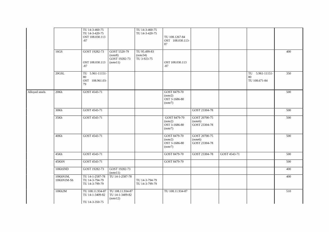
TU 14-3-460-75 TU 14-3-420-75 OST 108.030.113 -87
TU 14-3-460-75 TU 14-3-420-75
TU 108.1267-84 OST 108.030.113-87
16GS GOST 19282-73 OST 108.030.113 -87
GOST 5520-79 (note8) GOST 19282-73 (note11)
TU 95.499-83 (note34) TU 3-923-75
OST 108.030.113 -87
400
20GSL TU 5.961-11151-80 OST 108.961.03-79
TU 5.961-11151-80 TU 108.671-84
350
Alloyed steels 20Kh GOST 4543-71 GOST 8479-70 (note2) OST 3-1686-80 (note7)
500
30Kh GOST 4543-71
GOST 23304-78 500
35Kh GOST 4543-71
GOST 8479-70 (note2) OST 3-1686-80 (note7)
GOST 20700-75 (note6) GOST 23304-78
500
40Kh GOST 4543-71
GOST 8479-70 (note2) OST 3-1686-80 (note7)
GOST 20700-75 (note6) GOST 23304-78
500
45Kh
GOST 4543-71 GOST 8479-70 GOST 23304-78 GOST 4543-71 500
45KhN GOST 4543-71
GOST 8479-70 500
10KhSND
GOST 19282-73 GOST 19282-73 (note11)
400
10KhN1M, 10KhN1M-Sh
TU 14-1-2587-78 TU 14-3-794-79 TU 14-3-799-79
TU 14-1-2587-78 TU 14-3-794-79 TU 14-3-799-79
400
10Kh2M TU 108.11.934-87 TU 14-1-3409-82 TU 14-3-350-75
TU 108.11.934-87 TU 14-1-3409-82 (note12)
TU 108.11.934-87 510
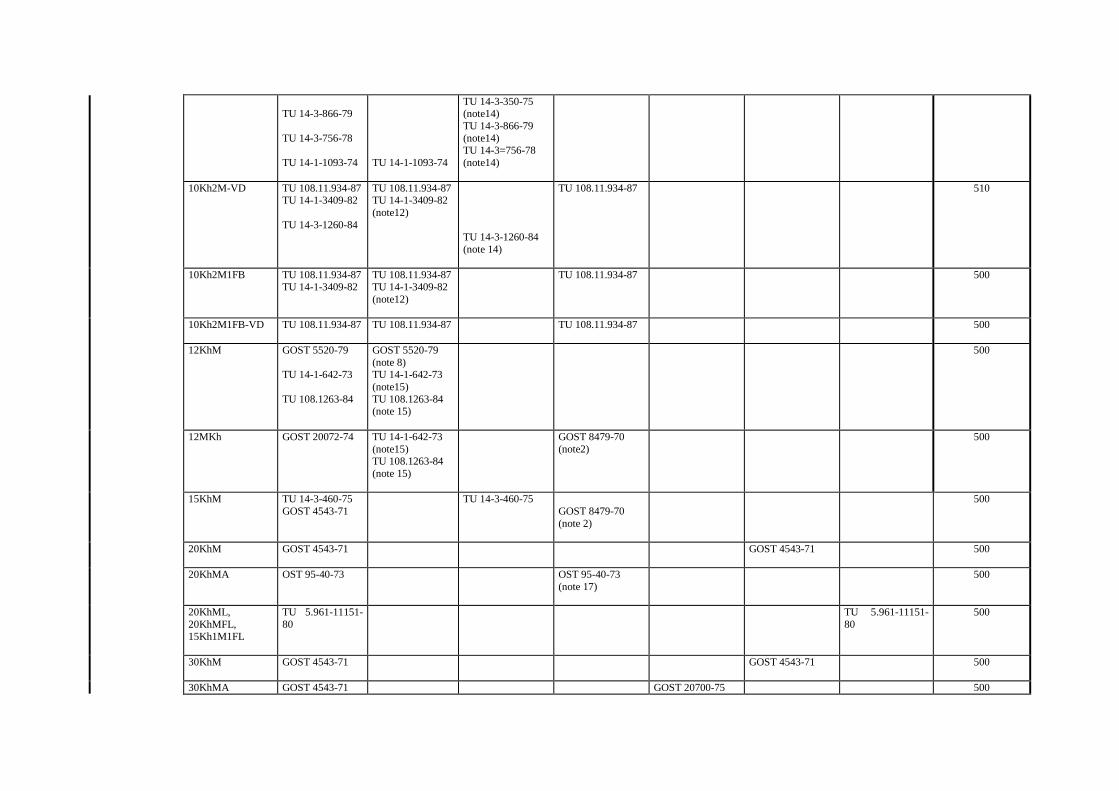
TU 14-3-866-79 TU 14-3-756-78 TU 14-1-1093-74
TU 14-1-1093-74
TU 14-3-350-75 (note14) TU 14-3-866-79 (note14) TU 14-3=756-78 (note14)
10Kh2M-VD TU 108.11.934-87 TU 14-1-3409-82 TU 14-3-1260-84
TU 108.11.934-87 TU 14-1-3409-82 (note12)
TU 14-3-1260-84 (note 14)
TU 108.11.934-87 510
10Kh2M1FB TU 108.11.934-87 TU 14-1-3409-82
TU 108.11.934-87 TU 14-1-3409-82 (note12)
TU 108.11.934-87 500
10Kh2M1FB-VD TU 108.11.934-87
TU 108.11.934-87
TU 108.11.934-87
500
12KhM GOST 5520-79 TU 14-1-642-73 TU 108.1263-84
GOST 5520-79 (note 8) TU 14-1-642-73 (note15) TU 108.1263-84 (note 15)
500
12MKh GOST 20072-74 TU 14-1-642-73 (note15) TU 108.1263-84 (note 15)
GOST 8479-70 (note2)
500
15KhM TU 14-3-460-75 GOST 4543-71
TU 14-3-460-75 GOST 8479-70 (note 2)
500
20KhM GOST 4543-71
GOST 4543-71 500
20KhMA OST 95-40-73 OST 95-40-73 (note 17)
500
20KhML, 20KhMFL, 15Kh1M1FL
TU 5.961-11151-80
TU 5.961-11151-80
500
30KhM
GOST 4543-71 GOST 4543-71 500
30KhMA GOST 4543-71 GOST 20700-75 500
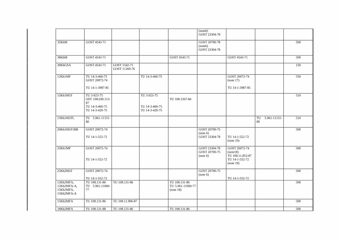
(note6) GOST 23304-78
35KhM GOST 4543-71 GOST 20700-78 (note6) GOST 23304-78
500
38KhM GOST 4543-71
GOST 4543-71 GOST 4543-71 500
30KhGSA GOST 4543-71 GOST 1542-71 GOST 11269-76
150
12Kh1MF TU 14-3-460-75 GOST 20072-74 TU 14-1-3987-85
TU 14-3-460-75 GOST 20072-74 (note 17) TU 14-1-3987-85
550
15Kh1M1F TU 3-923-75 OST 108.030.113-87 TU 14-3-460-75 TU 14-3-420-75
TU 3-923-75 TU 14-3-460-75 TU 14-3-420-75
TU 108.1267-84
510
15Kh1M1FL TU 5.961-11151-80
TU 5.961-11151-80
510
20Kh1M1F1BR
GOST 20072-74 TU 14-1-552-72
GOST 20700-75 (note 6) GOST 23304-78
TU 14-1-552-72 (note 19)
500
25Kh1MF
GOST 20072-74 TU 14-1-552-72
GOST 23304-78 GOST 20700-75 (note 6)
GOST 20072-74 (note18) TU 108.11.853-87 TU 14-1-552-72 (note 19)
500
25Kh2M1F GOST 20072-74 TU 14-1-552-72
GOST 20700-75 (note 6)
TU 14-1-552-72
500
12Kh2MFA, 12Kh2MFA-A, 15Kh2MFA, 15Kh2MFA-A
TU 108.131-86 TU 5.961-11060-77
TU 108.131-86 TU 108.131-86 TU 5.961-11060-77 (note 18)
500
15Kh2MFA TU 108.131-86 TU 108.11.906-87
500
18Kh2MFA TU 108.131-88 TU 108.131-86 TU 108.131-86 500
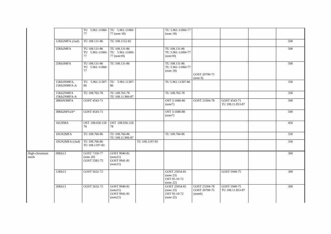
TU 5.961-11060-77
TU 5.961-11060-77 (note 18)
TU 5.961-11060-77 (note 18)
12Kh2MFA (clad)
TU 108.131-86 TU 108.1152-82 500
25Kh2MFA TU 108.131-86 TU 5.961-11060-77
TU 108.131-86 TU 5.961-11060-77 (note18)
TU 108.131-86 TU 5.961-11060-77 (note18)
500
25Kh3MFA TU 108.131-86 TU 5.961-11060-77
TU 108.131-86 TU 108.131-86 TU 5.961-11060-77 (note 18)
GOST 20700-75 (note 6)
500
15Kh3NMFA, 15Kh3NMFA-A
TU 5.961.11307-86
TU 5.961.11307-86
TU 5.961.11307-86 350
15Kh2NMFA 15Kh2NMFA-A
TU 108.765-78 TU 108.765-78 TU 108.11.906-87
TU 108.765-78 350
38KhN3MFA GOST 4543-71 OST 3-1686-80 (note7)
GOST 23304-78 GOST 4543-71 TU 108.11.853-87
500
38Kh2MYuA* GOST 4543-71 OST 3-1686-80 (note7)
500
16GNMA OST 108.030.118-78
OST 108.030.118-78
450
10GN2MFA TU 108.766-86 TU 108.766-86 TU 108.11.906-87
TU 108.766-86 350
10GN2MFA (clad) TU 108.766-86 TU 108.1197-83
TU 108.1197-83 350
High-chromium steels
08Kh13 GOST 7350-77 (note 20) GOST 5582-75
GOST 9940-81 (note21) GOST 9941-81 (note21)
300
12Kh13 GOST 5632-72 GOST 25054-81 (note 23) OST 95-10-72 (note 22)
GOST 5949-75 300
20Kh13 GOST 5632-72 GOST 9940-81 (note21) GOST 9941-81 (note21)
GOST 25054-81 (note 23) OST 95-10-72 (note 22)
GOST 23304-78 GOST 20700-75 (note6)
GOST 5949-75 TU 108.11.853-87
300
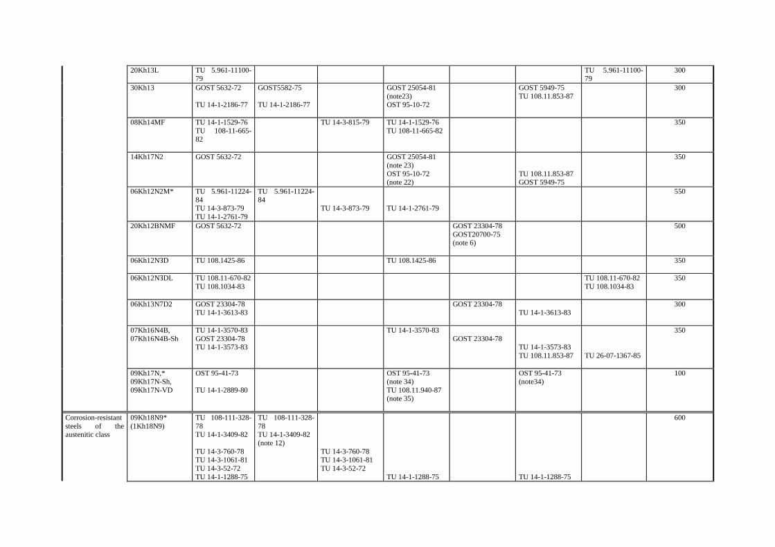
20Kh13L TU 5.961-11100-79
TU 5.961-11100-79
300
30Kh13 GOST 5632-72 TU 14-1-2186-77
GOST5582-75 TU 14-1-2186-77
GOST 25054-81 (note23) OST 95-10-72
GOST 5949-75 TU 108.11.853-87
300
08Kh14MF TU 14-1-1529-76 TU 108-11-665-82
TU 14-3-815-79 TU 14-1-1529-76 TU 108-11-665-82
350
14Kh17N2 GOST 5632-72 GOST 25054-81 (note 23) OST 95-10-72 (note 22)
TU 108.11.853-87 GOST 5949-75
350
06Kh12N2M* TU 5.961-11224-84 TU 14-3-873-79 TU 14-1-2761-79
TU 5.961-11224-84
TU 14-3-873-79
TU 14-1-2761-79
550
20Kh12ВNMF GOST 5632-72 GOST 23304-78 GOST20700-75 (note 6)
500
06Kh12NЗD TU 108.1425-86
TU 108.1425-86 350
06Kh12NЗDL TU 108.11-670-82 TU 108.1034-83
TU 108.11-670-82 TU 108.1034-83
350
06Kh13N7D2 GOST 23304-78 TU 14-1-3613-83
GOST 23304-78 TU 14-1-3613-83
300
07Kh16N4B, 07Kh16N4B-Sh
TU 14-1-3570-83 GOST 23304-78 TU 14-1-3573-83
TU 14-1-3570-83 GOST 23304-78
TU 14-1-3573-83 TU 108.11.853-87
TU 26-07-1367-85
350
09Kh17N,* 09Kh17N-Sh, 09Kh17N-VD
OST 95-41-73 TU 14-1-2889-80
OST 95-41-73 (note 34) TU 108.11.940-87 (note 35)
OST 95-41-73 (note34)
100
Corrosion-resistant steels of the austenitic class
09Kh18N9* (1Kh18N9)
TU 108-111-328-78 TU 14-1-3409-82 TU 14-3-760-78 TU 14-3-1061-81 TU 14-3-52-72 TU 14-1-1288-75
TU 108-111-328-78 TU 14-1-3409-82 (note 12)
TU 14-3-760-78 TU 14-3-1061-81 TU 14-3-52-72
TU 14-1-1288-75
TU 14-1-1288-75
600
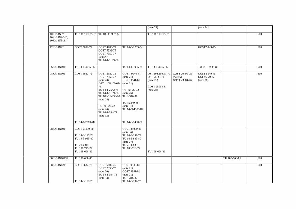
(note 24)
(note 24)
10Kh18N9*, 10Kh18N9-VD, 10Kh18N9-Sh
TU 108.11.937-87 TU 108.11.937-87 TU 108.11.937-87 600
12Kh18N9* GOST 5632-72 GOST 4986-79 GOST 5532-75 GOST 7350-77 (note20) TU 14-1-3199-88
TU 14-3-1233-84 GOST 5949-75 600
06Kh18N10T
TU 14-1-3935-85 TU 14-1-3935-85 TU 14-1-3935-85 TU 14-1-3935-85 600
08Kh18N10T GOST 5632-72 TU 14-1-2583-78
GOST 5582-75 GOST 7350-77 (note 20) OST 108.109.01-79 TU 14-1-2542-78 TU 14-1-3199-88 TU 108-11-930-80 (note 25) OST 95-29-72 (note 26) TU 14-1-394-72 (note 33)
GOST 9940-81 (note 21) GOST 9941-81 (note 21) OST 95-29-72 (note 26) TU 3-316-87 TU 95.349-86 (note 31) TU 14=3-1109-82 TU 14-3-1490-87
OST 108.109.01-79 OST 95-29-72 (note 26) GOST 25054-81 (note 23)
GOST 20700-75 (note 6) GOST 23304-76
GOST 5949-75 OST 95-29-72 (note 26)
600
08Kh18N10T GOST 24030-80 TU 14-3-197-73 TU 14-3-935-80 TU 21-4-83 TU 108-713-77 TU 108-668-86
GOST 24030-80 (note 36) TU 14-3-197-73 TU 14-3-935-80 (note 27) TU 21-4-83 TU 108-713-77
TU 108-668-86
08Kh18N10TSh TU 108-668-86
TU 108-668-86 600
08Kh18N12T GOST 5632-72 TU 14-3-197-73
GOST 5582-75 GOST 7350-77 (note 20) TU 14-1-394-72 (note 33)
GOST 9940-81 (note 21) GOST 9941-81 (note 21) TU 3-316-87 TU 14-3-197-73
600
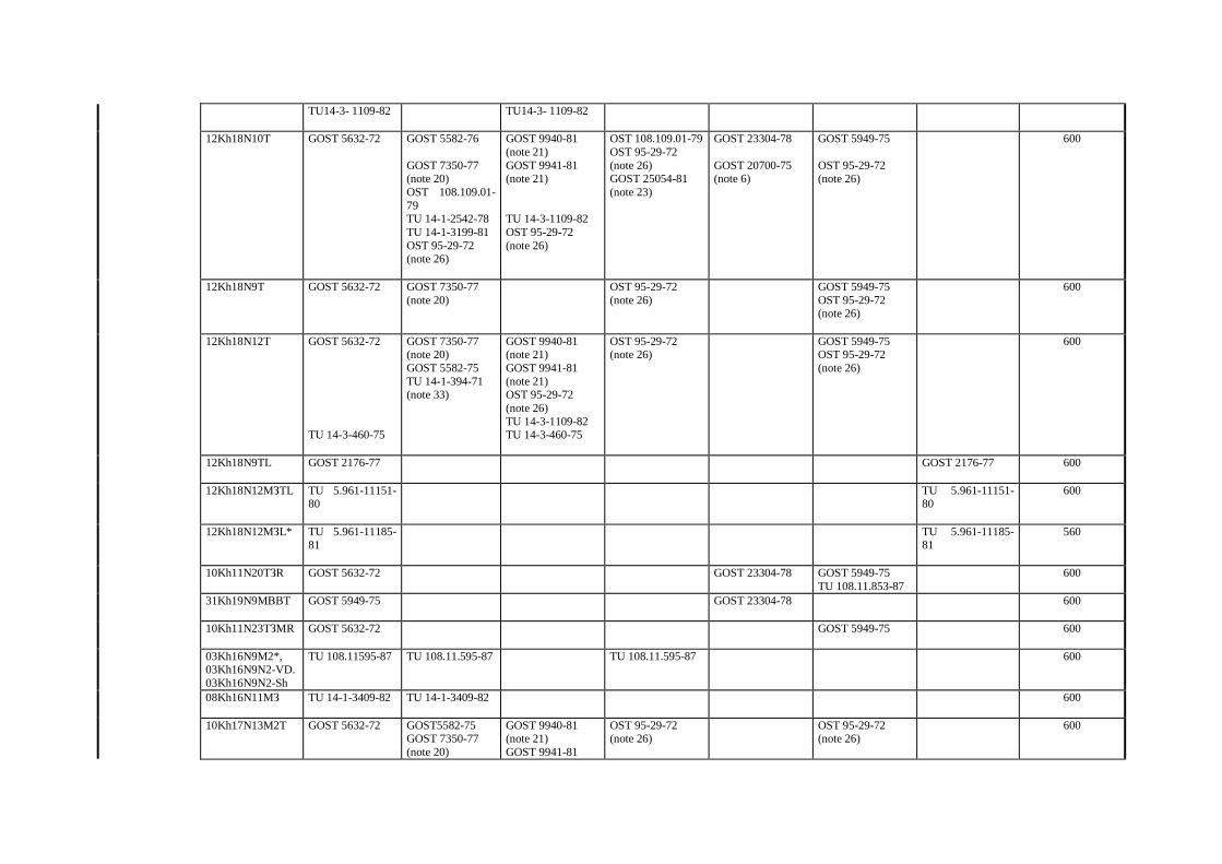
TU14-3- 1109-82 TU14-3- 1109-82
12Kh18N10T GOST 5632-72 GOST 5582-76 GOST 7350-77 (note 20) OST 108.109.01-79 TU 14-1-2542-78 TU 14-1-3199-81 OST 95-29-72 (note 26)
GOST 9940-81 (note 21) GOST 9941-81 (note 21) TU 14-3-1109-82 OST 95-29-72 (note 26)
OST 108.109.01-79 OST 95-29-72 (note 26) GOST 25054-81 (note 23)
GOST 23304-78 GOST 20700-75 (note 6)
GOST 5949-75 OST 95-29-72 (note 26)
600
12Kh18N9T GOST 5632-72 GOST 7350-77 (note 20)
OST 95-29-72 (note 26)
GOST 5949-75 OST 95-29-72 (note 26)
600
12Kh18N12T GOST 5632-72 TU 14-3-460-75
GOST 7350-77 (note 20) GOST 5582-75 TU 14-1-394-71 (note 33)
GOST 9940-81 (note 21) GOST 9941-81 (note 21) OST 95-29-72 (note 26) TU 14-3-1109-82 TU 14-3-460-75
OST 95-29-72 (note 26)
GOST 5949-75 OST 95-29-72 (note 26)
600
12Kh18N9TL GOST 2176-77 GOST 2176-77 600
12Kh18N12MЗTL TU 5.961-11151-80
TU 5.961-11151-80
600
12Kh18N12MЗL* TU 5.961-11185-81
TU 5.961-11185-81
560
10Kh11N20TЗR GOST 5632-72 GOST 23304-78 GOST 5949-75 TU 108.11.853-87
600
31Kh19N9MВBT GOST 5949-75
GOST 23304-78 600
10Kh11N23TЗMR GOST 5632-72
GOST 5949-75 600
03Kh16N9M2*, 03Kh16N9N2-VD. 03Kh16N9N2-Sh
TU 108.11595-87 TU 108.11.595-87 TU 108.11.595-87 600
08Kh16N11MЗ TU 14-1-3409-82
TU 14-1-3409-82 600
10Kh17N13M2T GOST 5632-72 GOST5582-75 GOST 7350-77 (note 20)
GOST 9940-81 (note 21) GOST 9941-81
OST 95-29-72 (note 26)
OST 95-29-72 (note 26)
600
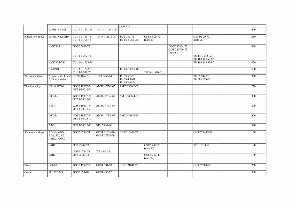
(note 21) 03Kh17N14MЗ TU 14-1-1541-75 TU- 14-1-1541-75
600
Nickel-iron alloys 03Kh21N32M3B* TU 14-1-769-73 TU 14-3-758-78
TU 14-1-2511-78 TU 3-342-78 TU 14-3-758-78
OST 95-29-72 (note 26)
OST 95-29-72 (note 26)
550
KhN35ВT
GOST 5632-72 TU 14-1-272-72
GOST 23304-78 GOST 20700-75 (note 6)
TU 14-1-272-72 TU 108.11.853-87
600
KhN35ВT-VD TU 14-1-1665-76
TU 108.11.853-87 600
Kh20N46B TU 14-3-1202-83 TU 14-1-516-73
TU 14-3-1202-83 TU 14-1-516-73
600
Zirconium alloys Alloys with 1 and 2,5% of niobium
TU 95.166-83 TU 95.252-74 TU 95.535-78 TU 95.406-81 TU 95.240-74
TU 95.242-78 TU 001.205-82
360
Titanium alloys ВT1-0, ВT1-1
GOST 19807-74 OST 1-90013-71
AMTU 475-2-67 AMTU 386-2-65 250
OTTch-1 GOST 19807-74 OST 1-90013-71
AMTU 475-2-67 AMTU 386-4-65 350
ВT5-1 GOST 19807-74 OST 1-90013-71
AMTU 475-7-67 500
OTTch
GOST 19807-74 OST 1-90013-71
AMTU 475-3-67 AMTU 386-5-65 400
AT-2 OST 1-90013-71 STU 559-6-69
520
Aluminium alloys ADOO, ADO, AD1, AD, AВ, AMG2, AMG3
GOST 4784-74 GOST 21631-76 GOST 17232-79
GOST 18482-79 GOST 21488-76 150
SAВ1
OST 95-42-73 GOST 4784-74
TU 1-1-21-71
OST 95-42-73 (note 32)
STU 101-3-70 190
SAВ2 OST 95-42-73 OST 95-42-43 (note 32)
190
Brass LO62-1
GOST 15527-70
GOST 931-78
GOST 21646-76 GOST 2060-73 250
Copper
M1, M2, M3 GOST 859-78 GOST 495-77 360
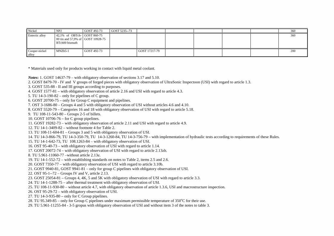
Nickel NP2 GOST 492-73 GOST 5235--73 360
Entectic alloy 42,1% of OВTch-00 tin and 57,9% of ВTch00 bismuth
GOST 860-75 GOST 10928-75
360
Cooper-nickel alloy
MNZh5-1 GOST 492-73 GOST 17217-79 200
* Materials used only for products working in contact with liquid metal coolant. Notes: 1. GOST 14637-79 – with obligatory observation of sections 3.17 and 5.10. 2. GOST 8479-70 - IV and V groups of forged pieces with obligatory observation of UltraSonic Inspectoon (USI) with regard to article 1.3. 3. GOST 535-88 - II and III groups according to purposes. 4. GOST 1577-81 – with obligatory observation of article 2.16 and USI with regard to article 4.3. 5. TU 14-3-190-82 – only for pipelines of C group. 6. GOST 20700-75 – only for Group C equipment and pipelines. 7. OST 3-1686-80 – Groups 4 and 5 with obligatory observation of USI without articles 4.6 and 4.10. 8. GOST 5520-79 – Categories 16 and 18 with obligatory observation of USI with regard to article 5.18. 9. TU 108-11-543-80 – Groups 2-5 of billets. 10. GOST 10706-76 – for C group pipelines. 11. GOST 19282-73 – with obligatory observation of article 2.11 and USI with regard to article 4.9. 12. TU 14-1-3409-82 – without footnote 4 for Table 2. 13. TU 108-11-604-81 – Groups 3 and 5 with obligatory observation of USI. 14. TU 14-3-866-79, TU 14-3-350-79, TU 14-3-1260-84, TU 14-3-756-79 – with implementation of hydraulic tests according to requirements of these Rules. 15. TU 14-1-642-73, TU 108.1263-84 – with obligatory observation of USI. 16. OST 95-40-73 – with obligatory observation of USI with regard to article 1.14. 17. GOST 20072-74 – with obligatory observation of USI with regard to article 2.13zh. 8. TU 5.961-11060-77 –without article 2.13е. 19. TU 14-1-552-72 – with establishing standards on notes to Table 2, items 2.5 and 2.6. 20. GOST 7350-77 – with obligatory observation of USI with regard to article 3.10b. 21. GOST 9940-81, GOST 9941-81 – only for group C pipelines with obligatory observation of USI. 22. OST 95-1--72 – Groups IV and V, article 2.13. 23. GOST 25054-81 – Groups 4, 4K, 5 and 5K with obligatory observation of USI with regard to article 3.3. 24. TU 14-1-1288-75 – after thermal treatment with obligatory observation of USI. 25. TU 108-11-930-80 – without article 4.7, with obligatory observation of article 1.3.6, USI and macrostructure inspection. 26. OST 95-29-72 – with obligatory observation of USI. 27. TU 14-3-935-80 – only for C Group pipelines. 28. TU 95.349-85 – only for Group C pipelines under maximum permissible temperature of 350оC for their use. 29. TU 5.961-11255-84 - 3-5 gropus with obligatory observation of USI and without item 3 of the notes to table 3.
30. TU 95.499-83 - maximum permissible temperature of the use is 200оC. 31. TU 24-3-15-768-74 - II -V groups of forged pieces with obligatory observation of USI. 32. OST 95-42-73 – Group II of forged pieces. 33. TU 14-394-72 - with obligatory observation of USI. 34. OST 95-41-73 – for fabrication of magnetic conductor of electromagnetic clatches of gears of Control and Protection Systems. Groups III and IV – with obligatory inspection of macrostructure according to article 1.15 and USI with regard to article 1.16. 35. TU 108.11940-78 – for devices of electric facilities. 36. GOST 24030-80 – A Group.
ANNEX 10 (recommended)
REQUIREMENTS FOR TECHNICAL SPECIFICATIONS ON SEMIPRODUCTS It is recommended to provide for the following types of inspection in development of technical specifications for semiproducts (plates, forged pieces, casts, bars, pipes, etc.):
1) Analysis of chemical composition of the material; 2) Cheking of geometry dimensions; 3) Visual inspection of the surface condition; 4) Metallographic study (microcontrol) with a purpose to discover contraction cavities, bubbles, non-metalic admixtures, size of grains, amount of α-phase (for steels of austenitic class), microstructure (for pearlitic steels); 5) Definition of mechanical properties (Rm, Rpo,2, A5, z) under 20оС and design temperature; 6) Determination or confirmation of the critical brittle temperature; 7) Estimation of plasticity and process properties for cold pressing and bending (dispensing, flattening, bend, etc.); 8) Non-destructive ispection; 9) Hydraulic tests (for hollow semiproducts); 10) Intergarnular corrosion resistance tests (for steels of austenitic class).
Standards for estimation of quality shall be given in technical specifications. A scope of technical specifications mentioned above is recommended for equipment and pipelines of A and B groups and can be reduced for equipment and pipelines of C group.
ANNEX 11 (obligatory)
REQUIREMENTS FOR THE USE AND QUALIFICATION OF NEW MATERIALS
1. General Provisions
1.1. Principles of ascription of base and welding (cladding) materials to the new ones are given in item 3.4.1 of the basic text of these Rules. 1.2. Procedure on submission of the reports on qualification and obtaining the right for the use of new materials is presented in item 3.4.3 of the basic text of these Rules. 1.3. This Annex sets up a list and scope of data that shall be presented in a report on qualification.
2. Information on new materials
2.1. General Provisions. 2. 1.1. The following data shall be indicated while presenting new materials for their inclusion into the list of materials, which use for manufacture of equipment and pipelines, is authorized:
1) General data; 2) Physical-mechanical properties; 3) Parameters of brittle fracture resistance; 4) Parameters of cyclic strength; 5) Parameters of long-term strength and creep; 6) Parameters of corrosion resistance.
2.2. General Information 2.2.1. The following data shall be provided for the base material: 1) Chemical composition (with indication of the poison composition); 2) Type and method of semiproduct production; 3) Maximum permissible temperature for the use of the material, Тmax ; 4) Working media where the use of material is permitted; 5) Thermal treatment; 6) Maximum acceptable neutron fluence (if a material is intended for the use under irradiation to neutrons with fluence F ≥ 1022 neutron/m2 (Е ≥ 0,5 MEv)), as well as neutron fluence and temperature during tests; 7) Data from certificates on semiproducts used for tests, registration numbers of meltings; 8) Diagram of cutting out specimens from semiproducts; 9) A list of standards or technical specifications for the semiproduct; 10) Purpose of the material. 2.2.2. The following data shall be presented for welding and cladding materials: 1) Welding method;
2) Combination of welding (cladding) and base materials (by their grades); 3) Chemical composition of the deposited metal (weld metal) with indication of limiting values for the content of elements and injurous impurities; 4) Necessity and modes of preliminary and concurrent heating; 5) Necessity, type and modes of thermal treatment of welded joints and fused products; 6) Maximum permissible neutron fluence (if material is intended for work under neutron irradiation with fluence F ≥ 1022 neutron/m2 (Е ≥ 0,5 MeV)), as well as neutron fluence and temperature during tests. 2.2.3. Data defining tendency of materials to decarbonization and local fracture shall be presented for materials intended to work in a contact with liquid metal coolant. 2.3. Physical-chemical Properties. 2.3.1. Data on the following properties that were actually obtained during tests and are ensured shall be presented for base material and deposited (weld) material: 1) Ultimate strength Rm;
2) Yield limit Rp0,2;
3) Relative elongation А5; 4) Relative reduction z. 2.3.2. Values of ultimate strength and angle of bending that were obtained during tests and are ensured shall be presented for welded joints. 2.3.3. Properties mentioned in items 2.3.1 and 2.3.2 shall be determined withing the temperature range from 20оС up to Tmax in every 50оС, as well as under temperature of (Тmax+ 25)оС and (Тmax+50)oC. Angle of bending of the welded joint is defined only under temperature of 20оС. 2.3.4. Data on changing of mechanical properties mentioned in items 2.3.1 and 2.3.2 (except of angle of bending) under temperature of 20о
С, 270оС and Тmax and maximum permissible neutron fluence for the considered material shall be presented for base materials and deposited (weld) materials, and welded joints and anticorrosive cladding intended to work under neutron irradiation. 2.3.5. For the newly proposed materials absence of deterioration of mechanical properties (in the absence of neutron irradiation) below the ensured level during the whole operational life time shall be confirmed or quantitave data that characterize variation of mechanical properties in time shall be presented. 2.3.6. Values of the following physical parameters obtained during tests shall be presented for the base material and deposited (weld) material:
1) Coefficient of elasticity Е; 2) Linear expansion coefficient α; 3) Coefficient of thermal conductivity λ; 4) Density γ.
2.3.7. Parameters mentioned in item 2.3.6 shall be defined within the temperature range from 20о
С up to Tmax in each 100оС, as well as under temperature of (Tmax +50) оС. 2.4. Characteristics of brittle fracture resistance 2.4.1. The following characteristics shall be defined for the base metal, metal of weld and peri-weld area:
1) Fracture viscosity – temperature relation within the temperature range from (Тk - 100) оС up to (Тk + 50) оС (Presentation of КIc values received by conversion of critical values of contour integral IIc is allowed under temperatures above Тk); 2) Critical temperature of material embrittlement in the initial state Tk0 ;
3) Shift of embrittlement critical temperature due to temperature ageing∆TT ;
4) Shift of embrittlement critical temperature due to effect of cyclic failure rate∆TN ;
5) Shift of embrittlement critical temperature due to effect of irradiation∆TF .
2.4.2. Values of Tk0, ∆TT , ∆TN , ∆TF mentioned in item 2.4.1 shall be defined by techniques given in
Standards on Strength Analysis of Equipment and Pipelines of Nuclear Power Installations (Annex 2). Values of КIc (or IIc ) shall be defined by GOST 25.506-85. 2.4.3. It shall be confirmed for the newly proposed material that its interaction with a working medium does not result in deterioration of brittle fracture resistance characteristics below the level ensured in the qualification report or quantitative data reflecting a nature of this interaction shall be presented. The mentioned data are not required to be presented for materials that were not exposed to neutrons (F ≤ 1022 neutron/m2 with Е ≥ 0.5 MeV) and having the ultimate strength not more than 590 MPa (60 kgf/mm2) under temperature of 20оС, as well as for materials protected by anticorrosion coating from the side of working medium. 2.4.4. For the following cases it is not required to present characteristics mentioned in items 2.4.1 and 2.4.3 for materials intended for manufacture of products that are not exposed to neutron radiation (F ≤ 1022 neutron/m2
with Е ≥ 0.5 MeV):
1) If thickness of component parts is not more than 25 mm for material with yield limit up to 295 MPa (30 kgf/mm2) under temperature of 20оС; 2) If thickness of component parts is not more than 16 mm for material with yield limit higher than 295 MPa (30 kgf/mm2) under temperature of 20оС; 3) For materials made of corrosion-resistant steels of austenitic class and non-ferrous alloys.
2.5. Characteristics of long-term strength, plasticity and creep 2.5.1. Data on long-term strength, plasticity and creep are presented in cases when maximum temperature under which the new material can be used exceeds the following values (hereinafter identified as Тl): 450оС – for austenitic corrosion-resistant steels, nickel-chromium alloys and heat-resistant chrome-molybdanum steels; 350оС – for carbon and alloyed steels; 250о
С – for zirconium alloys; 20оС – for aluminium and titanium alloys. 2.5.2. Ensured and obtained during tests values of long-term strength and plasticity shall be presented for base metal and deposited (weld) metal. 2.5.3. Only ensured and actually obtained in tests values of long-term strength shall be presented for welded joints. 2.5.4. Characteristics mentioned in items 2.5.2 and 2.5.3 shall be presented within the temperature range from Тl (see item 2.1.2) up to Tmax in each 50оС, as well as for temperature of (Tmax + 25) оС and (Тmax + 50) оС. Characteristics of long-term strength shall be presented in tests with duration of up to 2 ⋅104 h. The ensured values shall be presented within the range from 1⋅104 up to 2 ⋅105 h. 2.5.5. Isohoric curve of deformation in stress – deformation coordinates shall be presented for base materials and weld metal for 10, 30, 102, 3⋅102, 103, 3⋅103, 104, 3⋅104, 105, 2⋅105 hours under temperatures mentioned in item 2.5.4. 2.5.6. Coefficients or relations reflecting effect of radiation on properties of long-term strength, plasticity and creep shall be presented for materials intended for work under neutron irradiation.
2.5.7. It shall be confirmed that the contact of material with working medium does not deteriorate characteristics of lonh-term strength, plasticity and creep below the ensured values, or data reflecting effect of working media shall be presented. 2.5.8. The respective tests shall be carried out according to techniques mentioned in Standards on Strength Analysis of Equipment and Pipelines of Nuclear Power Installations (Annex 2). 2.6. Characteristics of cyclic strength 2.6.1. Fatigue curves for the ensured values of strength and plasticity characteristics of base material and coefficients of cyclic strength deterioration of welded joints under temperature of 20о
С и Тmax shall be presented for base materials, their welded joints and anticorrosive surfacing intended to work under temperature less than Тl (see item 2.5.1). 2.6.2. Fatigue curves and coefficients of cyclic strength deterioration of welded joints for the ensured values of short- and log-term strength and plasticity characteristics shall be presented for base materials, their welded joints and anticorrosive surfacing intended to work under temperature higher than Тl taking into account time of material operation within the rage of cycles between 102 and 107. The mentioned curves shall be presented for the temperature rage from Тl up to (Tmax +50) oC in each 50 оС. 2.6.3. Absence of cyclic strength deterioration due to contact with working media, deformation ageing, hydrogen pickup and neutron irradiation shall be confirm in presentation of the new material. Or quantitative data shall be presented that account for an effect of these factors on cyclic strength for design temperatures and the range of their changes in the process of stress if the number of cycles and duration of service life are given. If a material is intended for the use under conditions when effect of this or that factor from the mentioned above does not exist, this fact shall be specifically indicated in the report on qualification tests. In this case it is not required to present corresponding data. 2.7. Characteristics of corrosion strength The following data shall be indicated in presenting new materials:
1) Values of total corrosion rate and nature of resistance to pitting (development of pit depth) and corrosion under stress in working media under assumed operational modes (including downtime modes) – for the base material and its welded joints; 2) Confirmation of intergranular corrosion resistance – for corrosion resistant steels and their welded joints, additionally to data according to item 1.
3. REQUIREMENTS FOR DRAWING UP QUALIFICATION REPORTS 3.1. A report containing test data and ensured properties anticipated by item 2 of this Annex, as well as standards or technical specifications on semiproduct or welding materials shall be presented upon completion of the tests. 3.2. All data, characteristics and coefficients shall be presented in a form of tables, graphical charts and narration with indication of test techniques (or references to documents defining those techniques), types of specimens, areas of their cutting out and orientation in the semiproduct or welded joint. 3.3. Reduction of a scope of data in comparison with that stipulated for by this Annex is allowed depending on assumed conditions for the material performance and taking into account a degree of difference (similarity) of properties of new and similar materials already authorized for their use. 3.4. Number of long-term and short-term tests, their duration and number of the tested fusions and standard size of semiproducts shall be sufficient for reliable defenition of the corresponding characteristics, their dependence on temperature and other factors, estimation of limits for data scattering taking into account effect of acceptable deviations in chemical composition of materials and in the technology for manufacture of semiproducts and products. 3.5.It is recommended to develop qualification test program before those tests and coordinate it with leading organization in development of these Rules and Leading interagency material science organization.
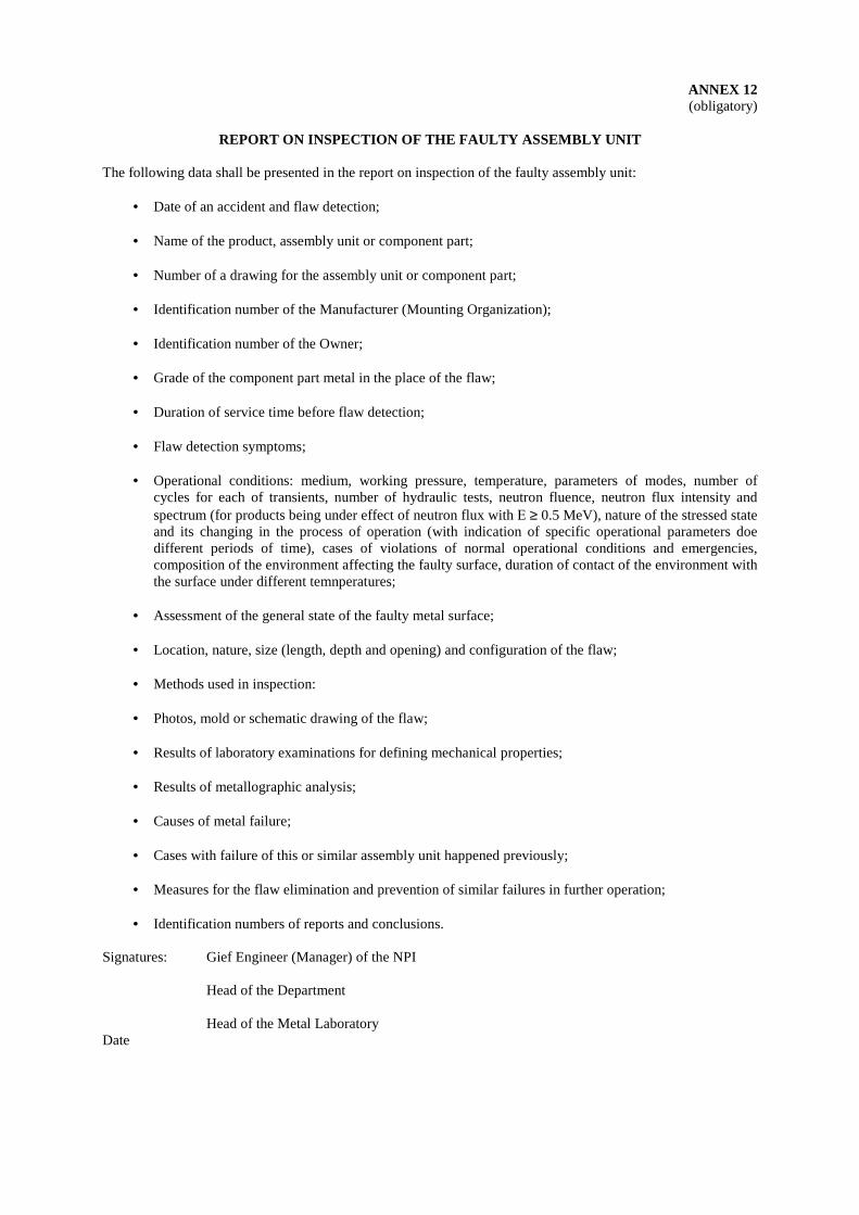
ANNEX 12 (obligatory)
REPORT ON INSPECTION OF THE FAULTY ASSEMBLY UNIT
The following data shall be presented in the report on inspection of the faulty assembly unit:
• Date of an accident and flaw detection; • Name of the product, assembly unit or component part; • Number of a drawing for the assembly unit or component part; • Identification number of the Manufacturer (Mounting Organization); • Identification number of the Owner; • Grade of the component part metal in the place of the flaw; • Duration of service time before flaw detection; • Flaw detection symptoms; • Operational conditions: medium, working pressure, temperature, parameters of modes, number of
cycles for each of transients, number of hydraulic tests, neutron fluence, neutron flux intensity and spectrum (for products being under effect of neutron flux with Е ≥ 0.5 MeV), nature of the stressed state and its changing in the process of operation (with indication of specific operational parameters doe different periods of time), cases of violations of normal operational conditions and emergencies, composition of the environment affecting the faulty surface, duration of contact of the environment with the surface under different temnperatures;
• Assessment of the general state of the faulty metal surface; • Location, nature, size (length, depth and opening) and configuration of the flaw; • Methods used in inspection: • Photos, mold or schematic drawing of the flaw; • Results of laboratory examinations for defining mechanical properties; • Results of metallographic analysis; • Causes of metal failure; • Cases with failure of this or similar assembly unit happened previously; • Measures for the flaw elimination and prevention of similar failures in further operation; • Identification numbers of reports and conclusions.
Signatures: Gief Engineer (Manager) of the NPI Head of the Department Head of the Metal Laboratory Date
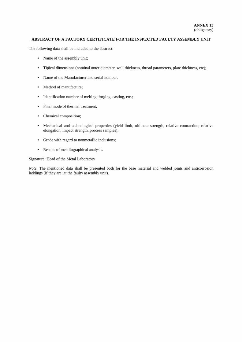
ANNEX 13 (obligatory)
ABSTRACT OF A FACTORY CERTIFICATE FOR THE INSPECTED FAULTY ASSEMBLY UNIT
The following data shall be included to the abstract:
• Name of the assembly unit; • Tipical dimensions (nominal outer diameter, wall thickness, thread parameters, plate thickness, etc); • Name of the Manufacturer and serial number; • Method of manufacture; • Identification number of melting, forging, casting, etc.; • Final mode of thermal treatment; • Chemical composition; • Mechanical and technological properties (yield limit, ultimate strength, relative contraction, relative
elongation, impact strength, process samples); • Grade with regard to nonmetallic inclusions; • Results of metallographical analysis.
Signature: Head of the Metal Laboratory Note. The mentioned data shall be presented both for the base material and welded joints and anticorrosion laddings (if they are iat the faulty assembly unit).
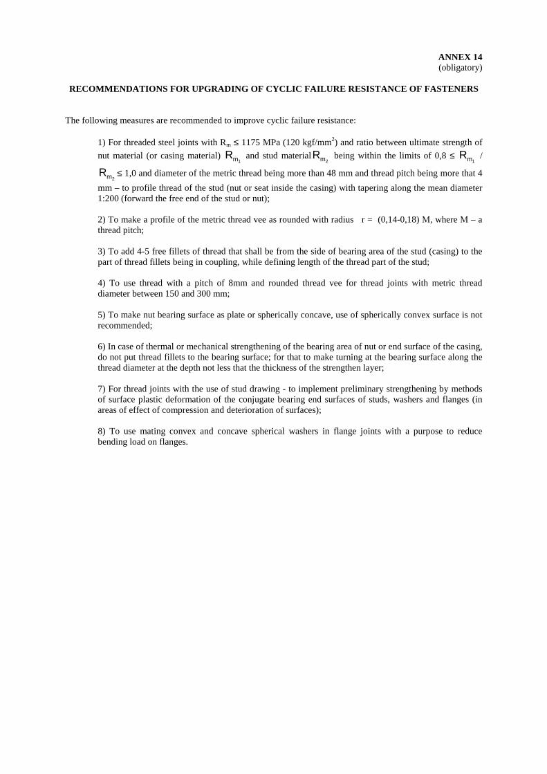
ANNEX 14 (obligatory)
RECOMMENDATIONS FOR UPGRADING OF CYCLIC FAILURE RESISTANCE OF FASTENERS
The following measures are recommended to improve cyclic failure resistance:
1) For threaded steel joints with Rm ≤ 1175 MPa (120 kgf/mm2) and ratio between ultimate strength of
nut material (or casing material) Rm1 and stud materialRm2
being within the limits of 0,8 ≤ Rm1 /
Rm2≤ 1,0 and diameter of the metric thread being more than 48 mm and thread pitch being more that 4
mm – to profile thread of the stud (nut or seat inside the casing) with tapering along the mean diameter 1:200 (forward the free end of the stud or nut); 2) To make a profile of the metric thread vee as rounded with radius r = (0,14-0,18) М, where М – a thread pitch; 3) To add 4-5 free fillets of thread that shall be from the side of bearing area of the stud (casing) to the part of thread fillets being in coupling, while defining length of the thread part of the stud; 4) To use thread with a pitch of 8mm and rounded thread vee for thread joints with metric thread diameter between 150 and 300 mm; 5) To make nut bearing surface as plate or spherically concave, use of spherically convex surface is not recommended; 6) In case of thermal or mechanical strengthening of the bearing area of nut or end surface of the casing, do not put thread fillets to the bearing surface; for that to make turning at the bearing surface along the thread diameter at the depth not less that the thickness of the strengthen layer; 7) For thread joints with the use of stud drawing - to implement preliminary strengthening by methods of surface plastic deformation of the conjugate bearing end surfaces of studs, washers and flanges (in areas of effect of compression and deterioration of surfaces); 8) To use mating convex and concave spherical washers in flange joints with a purpose to reduce bending load on flanges.
Federal Nuclear and Radiation Safety Authority of Russia (GOSATOMNADZOR OF RUSSIA)
NUCLEAR AND RADIATION SAFETY REGULATIONS
Appendix to Decree No 10 of Gosatomnadzor of Russia of December 27, 1999
ALTERATION No 1
To PNAE G-7-008-89 “Rules for Design and Safe Opera tion of Equipment and Pipelines of Nuclear Power Installati ons”
Effective since September 01, 2000
Moscow 2000
ALTERATION No 1
To PNAE G-7-008-89 “Rules for design and safe operation of equipment
and pipelines of nuclear power installations”
Contents of the alteration: 1. Title page. 1) To replace name of the federal executive authority “State
Committee of the USSR for supervision over safe implementation of activities in nuclear power engineering (Gosatomenergonadzor of the USSR)” by the name “Federal Nuclear and Radiation Safety Authority of Russia (Gosatomnadzor of Russia)”.
2) To write the following on the free space of the title page of PNAE G-7-008-89 below its title: “Is in force with alteration No 1 (see Decree of Gosatomnadzor of Russia No 10 of December 27, 1999). The following has been modified: items 1.1.3, 1.1.9, 1.2.1, 1.2.2, 1.2.4, 1.2.5, 1.2.6, 1.2.7, 1.2.9, 1.2.10, 1.2.11, 1.3.2, 2.1.11, 3.2.3, 3.4.3, 3.4.4, 4.1.2, 4.3.7, 5.1.3, 5.3.5, 5.3.6, 5.6.2, 5.6.4, 5.6.5, 6.2.1, 6.2.8, 7.1.6, 7.2.1, 7.4.2, 7.5.1, 7.5.2, 7.7.6, 7.8.2, 7.8.3, 7.8.10, 7.8.11, 8.1.1, 8.1.2, 8.1.4, 8.1.7, 8.1.8, 8.1.9, 8.1.10, 8.1.11, 8.1.12, 8.2.4, 8.2.5, 8.2.10, 8.2.13, 8.2.14, 8.2.15, 8.2.16, 8.2.17, 8.2.21, 8.2.22, 8.2.23, 9.1.3, 9.1.4, 9.1.6, 9.1.16, 9.2.2, 9.3.1, 11.1, 11.2; Sections 1.4, 8.3, 10, 11, 12; Table 3; Annexes 1, 3, 4, 5, 6, 7, 8, 9”.
2. Item 1.1.3. To replace words “Gosgortechnadzor of the USSR” by
“Gosgortechnadzor of Russia”. 3. Item 1.1.9. To replace “Chief Designer” by “Developers of the NPI design”. To delete the text starting from the words “for each NPI unit and
each reactor installation” and to add the following words: “at the stage of detail design of the reactor installation and NPI design”. After that the text of item 1.1.9 is the following:
1.1.9. Specific nomenclature of equipment and pipelines with indication of their belonging to A, B and C groups and their consideration among safety classes according to “Classification” is determined by the Developers of the NPI design at the stage of detail design of the reactor installation and NPI design”.
4. Item 1.2.1. Second paragraph.
To replace “permission of Gosatomenergonadzor of the USSR” by “licence of Gosatomnadzor of Russia”.
5. Item 1.2.2. To delete this item. 6. Item 1.2.4. To replace “permission of local offices of Gosatomenergonadzor of
the USSR” by “licence of Gosatomnadzor of Russia”. 7. Item 1.2.5. To replace “NPI owner” by “operating organization”. After that the
text of item 1.2.5 is the following: 1.2.5. It is allowed to implement repair activities during operation using welding according to technology developed by the operating organization and coordinated with the Designer and Manufacturer (Mounting organization) of repaired equipment and pipelines. The welding technology shall comply with requirements of Regulatory Document “Equipment and Pipelines of nuclear power installations. Welding and cladding. Basic provisions” (hereinafter mentioned as BP). 8. Item 1.2.6. 1) To replace words “according to the established procedure by
organizations developing this documentation. Local offices of Gosatomenergonadzor of the USSR shall be informed on these changes” by the following words “according to the procedure established by Gosatomnadzor of Russia”.
2) To replace “NPI owner” by “operating organization”. 3) Second paragraph to read in the following wording: “Terms of
reference (specifications) and design documentation (including technical specifications on semi products) on the imported equipment and pipelines shall be commended by Gosatomnadzor of Russia”. After that the wording of Item 1.2.6 is the following:
1.2.6. All changes in design and engineering documentation found necessary in manufacture, mounting and operation of equipment and pipelines shall be done according to the procedure established by Gosatomnadzor of Russia. Inserted changes shall be reflected in design documentation and documentation transferred to the operating organization by the Manufacturer and Mounting organization, including certificates-descriptors for equipment and pipelines.
Terms of reference (specifications) and design documentation (including technical specifications on semi products)
on the imported equipment and pipelines shall be commended by Gosatomnadzor of Russia. 9. Item 1.2.7. To replace words “NPI owner” by “NPI Management”. 10. Item 1.2.9. To replace “Gosatomenergonadzor of the USSR” by “with approval
of Gosatomnadzor of Russia”. After that the wording of Item 1.2.9 is the following:
1.2.9. Formats of certificates-descriptors and certificates on process channels, control rod holes (tubes and housings of control rod drives) and other channels are established by the Manufacturer in coordination with the Designer and with approval of Gosatomnadzor of Russia. 11. Item 1.2.10. To replace words “NPI owner” by “NPI Management”. 12. Item 1.2.11. To replace words “NPI owner” by “NPI Management”. After that the
wording of Item 1.2.11 is the following: 1.2.11. Based on the documentation submitted according to item 1.2.10 the NPI Management shall draw up a certificate-descriptor for pipelines in compliance with the format given in obligatory Annex 8. 13. Item 1.3.2. To add the following after the words “PD-3-3”: “and according to
other documents of Gosatomnadzor of Russia”. After that the wording of item1.3.2 is the following:
1.3.2. Officials and engineers dealing with design, manufacture, operation and repair of equipment and pipelines shall pass examination to check their knowledge of the corresponding Sections of these Rules and relevant standard-and-regulatory documentation at least once per three years. Examinations shall be arrange in accordance with a procedure established by “Standard provisions on the procedure for examination of managers and engineers working in nuclear power engineering to check their knowledge of safety rules, standards and instructions. RD-3-3” and according to other documents of Gosatomnadzor of Russia. 14. Section 1.4. Persons responsible for compliance with these
Rules. 1) To replace Item 1.4.1 by the following:
1.4.1. Officials working at enterprises involved in manufacture, mounting, operation and repair of NPI equipment and pipelines, as well as officials and engineers of design organizations guilty of violation of these Rules bear disciplinary, administrative and criminal responsibility. 2) Item 1.4.2. To replace “Gosatomenergonadzor of the USSR” by
“Gosatomnadzor of Russia”. 3) To delete items 1.4.3 - 1.4.5. 15. Item 2.1.11. To replace “NPI owner” by “NPI Management’. To replace “leading Interagency Material Organization” by “Leading
material science organization”. To replace the last sentence “The mentioned resolution shall be approved by the ministry (agency) owning the corresponding NPI and coordinated by Gosatomenergonadzor of the USSR” by the following sentence: “The mentioned resolutions shall be approved by the operating organization and commended by Gosatomnadzor of Russia”. After that the wording of item 2.1.11 is the following:
2.1.11. Based on the technical resolution developed by the NPI Management with participation of the Designer, Manufacturer and Leading material science organization service life of equipment and pipelines can be extended above the period mentioned in the certificate-descriptor. Strength analysis confirming a possibility to extend service life and reports on metal inspections shall be enclosed to the technical resolution. Moreover reports confirming that equipment can fulfill its functions during the extended service life in compliance with all requirements to nuclear, radiation and technical safety shall be presented. The mentioned resolutions shall be approved by the operating organization and commended by Gosatomnadzor of Russia. 16. Item 3.2.3. 1) First paragraph. To replace words “coordinated with Gosatomenergonadzor of the
USSR” by the following ”authorized for the use by Gosatomnadzor of Russia”.
2) Last paragraph. To replace “Gosatomenergonadzor of the USSR” by
“Gosatomnadzor of Russia”. 17. Item 3.4.3.
1) First paragraph. To supplement first sentence after words “the ministry (agency” by
words “or the operating organization”. To replace “Gosatomenergonadzor of the USSR” by
“Gosatomnadzor of Russia”. 2) Last paragraph. To replace words “with the leading organization for development of
these Ruses and with leading interagency metal science organization” by the words “with the leading metal science organization”, after that Item 3.4.3 to read as follows:
3.4.3. To include new materials to these Rules or BP the ministry (agency) or the operating organization interested in the use of new materials shall submit to Gosatomnadzor of Russia a corresponding proposal. A report containing data on tests and studies of new materials, as well as standards or technical specifications for semi-products and welding (cladding) materials shall accompany this proposal.
A list of data that shall be presented in the report is given in obligatory Annex 11.
The report shall be coordinated with the leading metal science organization. 18. Item 3.4.4. To replace words “and with Gosatomenergonadzor of the USSR”
by “and approved by Gosatomnadzor of Russia according to the established procedure”.
19. Item 4.1.2. First sentence. To replace words “with the leading branch metal science
organization” by “with the leading metal science organization”. 20. Item 4.3.7. Second paragraph. Last sentence. To replace “Gosatomenergonadzor of the USSR” by
“Gosatomnadzor of Russia”. 21. Item 5.1.3. First paragraph, second sentence. To replace words “Gosatomenergonadzor of the USSR shall
coordinate” by the following: “Gosatomnadzor of Russia shall approve”. After that the second sentence of Item 5.1.3 shall be read as follows:
Gosatomnadzor of Russia shall approve a possibility of such a replacement.
22. Item 5.3.5. To replace words “The Owner of equipment” by “NPI
Management”. 23. Item 5.3.6. To replace «General Designer of the NPI” by “developer of the NPI
design”. 24. Item 5.6.2. To replace words “The Owner of equipment and pipelines” by “NPI
Management”. 25. Item 5.6.4. The last sentence “ The comprehensive program shall be approved
by the management of the Designer and coordinated with the Owner of equipment and pipelines” to read as follows:
The comprehensive program shall be coordinated with the management of the Designer and approved by the NPI management.
26. Item 5.6.5. In the last sentence replace words “approved by the Management
of the Owner of equipment and pipelines” by “approved by the NPI Management”. After that to read the last sentence a follows:
The NPI Management shall approve the working program. 27. Item 6.2.1. Second paragraph.
To exclude words “in compliance with requirements of OPB-88".
28. Item 6.2.8. The first sentence “Throughput capacity of safety devices shall be
estimated in compliance with GOST 12.2.085-82” to read as follows: Throughput capacity of safety devices shall be estimated in compliance with requirements of regulatory documents of Gosatomnadzor of Russia. 29. Item 7.1.6. Sentence: "3) Upon decision of the Management of the Owner of equipment
and pipelines or the local office of Gosatomenergonadzor of the USSR” to read as follows:
“3) Upon decision of the NPI Management, operating organization or interregional office of Gosatomnadzor of Russia”.
30. Item 7.2.1. 1) First paragraph. First sentence. To replace words “ Organizations of ministries (agencies) under
which authority the NPI is” by the following: “the leading material science organization”, after that to read the first sentence of Item 7.2.1 as follows:
The leading material science organization develops the standard inspection programs that define a specific list of equipment and pipelines subject to inspection. 2) Second paragraph. The sentence “Standard programs shall be coordinated with the
General Designer of the NPI, General Designer of the reactor installation and Gosatomenergonadzor of the USSR” to read as follows:
Standard programs shall be coordinated with the developers of the RI and NPI design, approved by the operating organization and Gosatomnadzor of Russia in accordance with the established procedure”.
31. Item 7.4.2. To delete the last sentence “The standard program shall be coordinated with organizations according to item 7.2.1.”
32. Item 7.5.1. To replace words “the Owner of equipment and pipelines” by “the
NPI Management”, after than to read Item 7.5.1 as follows: 7.5.1. The NPI Management develops the working program (procedure) for the inspection based on the standard program (procedure, rules). 33. Item 7.5.2. The last sentence. To replace words “Management of the Owner of equipment and
pipelines” with “NPI Management” after that to the last sentence as follows:
The NPI Management approves the working program.
34. Item 7.7.6. To replace words «upon coordination with Gosatomnadzor of the
USSR by “upon approval by Gosatomnadzor of Russia”, after that to read Item 7.7.6 as follows:
7.7.6. If there is no a possibility (from the technical point of view) to install a sufficient number of reference specimens as defined in Item 7.7.5, the Designer can reduce this number upon approval of
Gosatomnadzor of Russia. But the number of reference specimens shall be enough for inspection carried out once per each eight years of operation. 35. Item 7.8.2. To delete this item. 36. Item 7.8.3.
1) First sentence.
To replace words “the Owner of equipment and pipelines” by “the NPI Management”.
2) Second sentence. To replace words “the Owner of equipment and pipelines” by “the
operating organization” after than Item 7.8.3 to read as follows: 7.8.3. The NPI Management shall carry out metal inspection with engagement of specialized organizations if necessary. The operating organization bears responsibility for inspection implementation. 37. Item 7.8.10. To replace words “the Management of the Owner of equipment and
pipelines” by “the NPI Management”, after that to read Item 7.7.10 as follows:
7.8.10. The NPI Management shall approve protocols or reports mentioned in Item 7.8.7. A record is inserted to the certificates-descriptors of vessels and pipelines after any inspection.
38. Item 7.8.11. To replace words “Заменить слова "to the ministry (agency) that
controls the Owner of equipment and pipelines and Gosatomenergonadzor of the USSR” by words “to the interregional office and HQ of Gosatomnadzor of Russia”.
To delete the second sentence, after that to read Item 7.8.11 as follows:
7.8.11. If results of inspection are unacceptable the reporting documents on the implemented inspection and suggested solutions are submitted to the interregional office and HQ of Gosatomnadzor of Russia. 39. Item 8.1.1. To replace words “local offices of Gosatomenergonadzor of the
USSR” by “interregional offices of Gosatomnadzor of Russia”, after that to read Item 8.1.1 as follows:
8.1.1. Equipment and pipelines subject to compliance with these Rules shall be registered in the interregional offices of Gosatomnadzor of Russia and taken for accounting by the Owner of equipment and pipelines after completion of their mounting and before implementation of technical examination.
40. Item 8.1.2. To replace the first sentence “8.1.2. Заменить первое
предложение "8.1.2. The following equipment and pipelines are subject to registration at the local offices of Gosatomenergonadzor of the USSR:” by the following sentence: "8.1.2. The following equipment and pipelines are subject to registration at the interregional offices of Gosatomnadzor of Russia:”.
41. Item 8.1.4. To replace words "at the local offices of Gosatomenergonadzor of
the USSR, bounds of equipment and pipeline registration are defined by the lists developed by the General Designer together with the NPI Management and Chief Engineering organization. The nomenclature and bounds of equipment and pipeline registration shall be coordinated with Gosatomenergonadzor of the USSR” by the following words "at the interregional offices of Gosatomnadzor of Russia, bounds of equipment and pipeline registration are defined by the lists developed by the NPI design developers together with the NPI Management. The nomenclature and bounds of equipment and pipeline registration shall be approved by the interregional offices of Gosatomnadzor of Russia", after that to read first paragraph of Item 8.1.4 as follows:
Specific nomenclature of equipment to be registered at the interregional offices of Gosatomnadzor of Russia, bounds of equipment and pipeline registration are defined by the lists developed by the NPI design developers together with the NPI Management. The nomenclature and bounds of equipment and pipeline registration shall be approved by the interregional offices of Gosatomnadzor of Russia. The mentioned lists shall be developed by the start of mounting activities. 42. Item 8.1.7. First sentence.
To replace words “at the local office of Gosatomenergonadzor of the USSR” by the following: “at the interregional office of Gosatomnadzor of Russia”.
43. Item 8.1.8.
1) First sentence. To replace words “at the local office of Gosatomenergonadzor of
the USSR” by the following: “at the interregional office of Gosatomnadzor of Russia”.
2) Second sentence. To replace sentence “Application of the Owner Management in
written” be sentence “Application of the NPI Management in written”. 44. Item 8.1.9. Second sentence.
To replace words “an inspector of Gosatomenergonadzor of the USSR” by the following: “an interregional office of Gosatomnadzor of Russia”.
45. Item 8.1.10. 1) First sentence. To replace words “by the local office of Gosatomenergonadzor of
the USSR” by the following: “by the interregional office of Gosatomnadzor of Russia”.
2) Second sentence. To replace words “to the Owner of equipment and pipelines” by the
following: “to the NPI Management”, after that to read Item 8.1.10 as follows:
8.1.10. In case of positive results of the review of the submitted documents and inspection of the work completion according to Item 8.1.9 of these Rules equipment and pipelines are registered by the interregional office of Gosatomnadzor of Russia in accordance with the established procedure. The certificate-descriptor together with documents enclosed is returned to the NPI Management. 46. Item 8.1.11. To replace words “the local office of Gosatomenergonadzor of the
USSR” by the following: “the interregional office of Gosatomnadzor of Russia”.
47. Item 8.1.12. To replace words “the local office of Gosatomenergonadzor of the
USSR” by the following: “the interregional office of Gosatomnadzor of Russia” and words “the Owner Management” by “the NPI Management”, after that to read Item 8.1.12 as follows:
8.1.12. The interregional office of Gosatomnadzor of Russia abolishes the registration upon receipt of the written application of
the NPI Management. The reason for registration abolishment shall be indicated in the application. 48. Item 8.2.4. Note.
To replace second and third sentences “As to accessibility with regard to the level of radiation, the Owner of equipment and pipelines and the local office of Gosatomenergonadzor of the USSR shall take a decision on this matter. The Designer and the Owner of equipment and pipelines in coordination with the local office of Gosatomnadzor of the USSR define if a place is inaccessible for the visual examination due to some other reasons” by the following:
Places that are inaccessible for visual examination due to radiation level are defined and justified by the operating organization and are approved by the interregional office of Gosatomnadzor of Russia. The Designer and the NPI Management define if a place is inaccessible for the visual examination due to some other reasons. The interregional office of Gosatomnadzor of Russia shall approve this.
49. Item 8.2.5. 1) First sentence. To replace words “coordinated with the local office of
Gosatomenergonadzor of the USSR” by the following: “approved by the interregional office of Gosatomnadzor of Russia”.
2) The last sentence. To replace sentence: “This procedure shall be coordinated with the
Designer of this equipment and local office of Gosatomenergonadzor of the USSR” by the following: “This procedure shall be approved by Gosatomnadzor of Russia according to the established procedure”, after that to read Item 8.2.5 as follows:
8.2.5. The NPI Management shall develop a list of equipment that is not accessible (or accessible with restrictions) for inner (outer) visual examinations due to design features or radiation level. This list shall be approved by the interregional office of Gosatomnadzor of Russia.
Remote devices and non-destructive inspection methods for metal and welded joints shall be used for technical examination of such equipment. For any specific case the NPI Management shall develop for this equipment a procedure of technical examination. This procedure shall be approved by Gosatomnadzor of Russia according to the established procedure. 50. Table 3, line 7. Column in the note.
Third sentence: "Upon coordination with the local office of Gosatomenergonadzor of the USSR registered the pipelines it is allowed to carry out hydraulic (pneumatic) tests of sections that were repaired during operation by welding (except of sections with longitudinal welds) during the next scheduled examination according to items 3 and 4 of this Table without examination of these sectors immediately after repair, if all new welded joints and repaired places were inspected in the established scope” to read as follows:
Upon justification of the operating organization and approval of the interregional office of Gosatomnadzor of Russia it is allowed to carry out hydraulic (pneumatic) tests of sections that were repaired during operation by welding (except of sections with longitudinal welds) during the next scheduled examination according to items 3
and 4 of this Table without examination of these sectors immediately after repair, if all new welded joints and repaired places were inspected in the established scope. 51. Table 3. 1) Line 11. Column 2. Sentence: “Equipment and pipelines – before the appointed time
upon request of Gosatomenergonadzor of the USSR or an engineer of the Owner supervising over equipment and pipelines (supervisor)” to read as follows:
Technical examination before the appointed time. 2) Note column. Sentence: “Engineer-inspector of Gosatomenergonadzor of the
USSR or supervisor defines a scope of technical examination” to read as follows:
Interregional office of Gosatomnadzor of Russia or the NPI Management defines a scope of the technical examination to be carried out before the appointed time upon their request. 52. Item 8.2.10. The text of this Item “Commission appointed by the Order of the
NPI Owner Manager carries out technical examination of equipment and pipelines subject to compliance with these Rules. The Commission works with participation and under supervision of the inspector of Gosatomenergonadzor of the USSR if technical examination of equipment and pipelines registered at the local office of Gosatomenergonadzor of the USSR is carried out” to read as follows:
8.2.10. Commission appointed by the Order of the NPI Manager carries out technical examination of equipment and pipelines
subject to compliance with these Rules. If technical examination of equipment and pipelines registered at the interregional offices of Gosatomnadzor of Russia is carried out, the NPI Management shall inform the resident inspection office of Gosatomnadzor of Russia at the NPI on the establishment of the commission and on the place and time of start of its activities. 53. Item 8.2.13. To replace words: “the Management of the Owner of equipment
and pipelines” by the following words: “the NPI Management”. 54. Item 8.2.14. The sentence: “Management of the Owner of equipment and
pipelines shall inform the inspector of Gosatomenergonadzor of the USSR on the readiness of equipment and pipelines for the technical examination at least 10 days prior to it” to read as follows:
8.2.14. The NPI Management shall inform the inspection office of Gosatomnadzor of Russia on the readiness of equipment and pipelines for the technical examination at least 10 days prior to it. 55. Item 8.2.15. 1) To replace words “the local office of Gosatomenergonadzor of
the USSR” by “the interregional office of Gosatomnadzor of Russia”.
2) To replace words “the Management of the Owner of equipment and pipelines” by “the NPI Management”.
3) To replace words “by the inspector of Gosatomenergonadzor of the USSR” by “by the representative of Gosatomnadzor of Russia”, after that to read Item 8.2.15 as follows:
8.2.15. The inspection office of Gosatomnadzor of Russia can postpone the technical examination of equipment and pipelines registered at the interregional office of Gosatomnadzor of Russia but not more than for three months upon receiving the technically justified written application of the NPI Management and in case of positive results of their visual examination in a working condition by the representative of Gosatomnadzor of Russia. 56. Item 8.2.16. 1) To replace words “at the structural units of
Gosatomenergonadzor of the USSR” by the following: “at the interregional office of Gosatomnadzor of Russia”.
2) To replace words “the Manager of the Owner of equipment and pipelines” by “the NPI Manager”.
To supplement with the following words: “in coordination with a person for the operating organization implementing supervision”, after that to read Item 8.2.16 as follows:
8.2.16. The technical examination of equipment and pipelines that are not registered at the interregional offices of Gosatomnadzor of Russia can be postponed for not more than three months upon the written permission of the Chief Engineer or NPI Manager and in coordination with a person for the operating organization implementing supervision. 57. Item 8.2.17. To delete words: “coordinated with the Owner of equipment and
pipelines and the local office of Gosatomenergonadzor of the USSR”. 58. Item 8.2.21. Third sentence.
To replace words: “equipment and pipelines registered at the structural units of Gosatomenergonadzor of the USSR the engineer-inspector of Gosatomenergonadzor of the USSR” by the following: “equipment and pipelines registered at the structural units of Gosatomnadzor of Russia the engineer-inspector of Gosatomnadzor of Russia”.
59. Item 8.2.22. 1) To replace words “the inspector of Gosatomenergonadzor of the
USSR” by the following: “the representative of Gosatomnadzor of Russia”.
2) To replace words: “the Management of the Owner of equipment and pipelines” by “the NPI Management”.
60. Item 8.2.23. 1) Firs paragraph. To replace words: “Заменить слова "to the ministry (agency)
controlling the Owner of equipment and pipelines, Chief Designer of the reactor installation, Manufacture and ministry controlling it and the local office of Gosatomenergonadzor of the USSR” by the following: “to the interregional office and HQ of Gosatomnadzor of Russia”, after that to the first paragraph as follows:
If flaws were detected in the base metal or welded joint the results of the visual examination of the defective junction shall be recorded in a form of the report (Annex 12). This reports (one copy to any address) together with the extract from the factory certificate (Annex 13), strength analysis and data on experimental estimation of stresses and temperatures, expert opinion (in case of corrosion defects) are submitted to the interregional office and HQ of
Gosatomnadzor of Russia. One copy of the report is inserted to the certificate-descriptor for equipment or pipelines. 2) Third paragraph.
The text of the paragraph: “A commission appointed by the ministry controlling the Owner of equipment and pipelines or by the Chief Engineer of the Owner (depending on the nature and scale of the revealed defects) makes a decision on measures for defect elimination and on a possibility of further operation of equipment and pipelines. The inspector of Gosatomenergonadzor of the USSR shall participate in this commission. Representatives of the Manufacturer (mounting organization), Designer and the leading metal science organization shall be members of this commission, if necessary” to read as follows:
A commission appointed by the operation organization or by the NPI management (depending on the nature and scale of the revealed defects) makes a decision on measures for defect elimination and on a possibility of further operation of equipment and pipelines. Representatives of the Manufacturer (mounting organization), Designer and the leading metal science organization can be members of this commission, if necessary.
The NPI Management shall inform the interregional office of Gosatomnadzor of Russia on the establishment of the commission, on a place and time of start of its work. 61. Section 8.3. Permission for implementation of commissioning
activities and operation of the NPI systems. To delete this section. 62. Item 9.1.3. To replace second sentence “Requirements for personnel
professional skills, procedure on preparation for examinations shall comply with OPB-88” by the following sentence: “ Requirements for personnel professional skills and its training are established according to the regulatory documents of Gosatomnadzor of Russia”.
63. Item 9.1.4. To replace words “inspection office of Gosatomenergonadzor of the
USSR” by the following: “resident inspection office of Gosatomnadzor of Russia at the NPI”.
64. Item 9.1.6. To replace words “at the structural units of Gosatomenergonadzor of the USSR” by the following: “at interregional offices of Gosatomnadzor of Russia”.
65. Item 9.1.16.
The text of the Item "It is prohibited to carry our different research studies and experiments on the operating equipment and pipelines without preliminary coordination with the Chief Engineer, General Designer, Scientific supervisor and Gosatomenergonadzor of the USSR and permission of the ministry (agency) controlling this NPI” to read as follows:
9.1.16. It is prohibited to carry our different research studies and experiments on the operating equipment and pipelines without preliminary coordination of the developers of the reactor installation design and nuclear power plant design, without permission of the operation organization and approval of Gosatomnadzor of Russia. 66. Item 9.2.2. The text of the Item “Change of equipment parameter limits
(design pressure, design temperature, maximum power level, coolant flow rate, rates of heating up and cooling down, maximum neutron fluence on the reactor vessel and channels) can be authorized only based on the technical solution justified by the appropriate calculations or experiments and amendment to the design approved according to the established procedure. This technical solution is developed by the Owner of equipment and pipelines and coordinated with the Chief Engineer, Scientific supervisor, General Designer, Manufacturer (mounting organization) and with Gosatomenergonadzor of the USSR, if necessary. Changes resulted from the taken technical solutions shall be reflected in certificates-descriptors for equipment and pipelines” to read as follows:
9.2.2. Change of equipment parameter limits (design pressure, design temperature, maximum power level, coolant flow rate, rates of heating up and cooling down, maximum neutron fluence on the reactor vessel and channels) can be authorized only based on the technical solution justified by the appropriate calculations or experiments and upon approval by Gosatomnadzor of Russia. This technical solution is developed by the operating organization and coordinated with developers of the RI and NPP designs, Manufacturer and leading metal science organization.
After changing of design parameters of the NPI according to procedure established by Gosatomnadzor of Russia, these changes shall be reflected in the certificates-descriptors for equipment and pipelines. 67. Item 9.3.1. 1) First paragraph.
To replace words: “by the ministry (agency) controlling an NPI” by the following: “by the operating organization”.
2) Second paragraph: “Changing of dates of the scheduled preventive maintenance and reduction of its scope can be allowed only in exceptional cases upon the written permission of the ministry (agency) controlling this NPI coordinated with the structural units of Gosatomenergonadzor of the USSR» to read as follows:
“Changing of dates of the scheduled preventive maintenance and reduction of its scope shall be justified by the NPI Management, approved by the operating organization and forwarded to the inspection office of Gosatomnadzor of Russia”, after that to read Item 9.3.1 as follows:
9.3.1. Requirements for implementation of scheduled preventive maintenances approved by the operating organization shall be met during operation of equipment and pipelines of the NPI.
Changing of dates of the scheduled preventive maintenance and reduction of its scope shall be justified by the NPI Management, approved by the operating organization and forwarded to the inspection office of Gosatomnadzor of Russia. 68. Section 10.Control over compliance with the Rules. To delete this Section. 69. Section 11.
To replace the title of Section 11 “Investigation of accidents, failures and casualties by the following: 11. Investigation of incidents and accidents.
70. Item 11.1. To read as follows: 11.1. Investigation of incidents and accidents occurred in operation of equipment and pipelines, notification of the operating organization, state regulatory bodies and other federal executive authorities shall be carried out in compliance with Federal Standards and Regulations in the area of nuclear energy use. 71. Item 11.2. To delete this Item. 72. Section 12. Conclusion.
The text of the Conclusion “Necessity and terms of putting of existing and operating equipment and pipelines as well as those being under manufacture, mounting or reconstruction within the period of these Rules
enforcement to the compliance with these Rules are specified individually for any specific case upon the statement of the corresponding ministries (agencies) and are coordinated with Gosatomenergonadzor of the USSR. In individual cases when compliance with some requirements of these Rules is impossible due to technical reasons, it is allowed to prepare justified technical resolutions developed by the Designer, Manufacturer (mounting organization), the Owner of equipment and pipelines depending on the responsibility of each of them according to Items 1.4.3-1.4.5.
The mentioned technical resolutions shall be coordinated with all organizations listed above, as well as with the leading material science organization, if those resolutions are within their responsibility, and with Gosatomenergonadzor – in all cases” to read as follows:
Necessity, terms and scope of putting NPI in compliance with these Rules are defined individually for any specific case according to the procedure established by Gosatomnadzor of Russia within the licensing of activities on construction and operation of NPI. 73. Annex 1 (reference annex). Main terms and definitions. 1) To exclude the following terms and their definitions: Normal operational conditions (for equipment and pipelines); Violations of normal operational conditions (for equipment and
pipelines); Emergency (for equipment and pipelines); Scientific supervisor. 2) To replace definition of term “Leading material science
organization – is an organization that is in charge of material selection, welding and quality assurance in manufacture of equipment and pipelines” by the following definition:
Leading material science organization – is an organization that was acknowledged by the corresponding body of the use of nuclear energy as an organization rendering services on material selection, welding and quality assurance in manufacture of equipment and pipelines to the operation or other organizations and carrying out review of design, engineering, process documentation and documents justifying nuclear and radiation safety of NPI and having a licence of Gosatomnadzor of Russia for these activities.
To supplement this Annex with new term and its definition: “Coordination of the leading material science organization – is a positive conclusion of the leading metal organization prepared upon request of the operating or other organizations”.
74. Annex 3 (obligatory). 1) Item 3, sub-items 6) and 9.
To replace sub-item “6) Documentation on non-compliances with design documentation coordinated with Gosatomenergonadzor of the USSR” by the following: “6) Documentation on non-compliances with the design documentation approved by Gosatomnadzor of Russia”.
To replace sub-item “9. Upon request of Gosatomenergonadzor of the USSR additional data can be included into certificates-descriptions” by the following: “9. Upon request of Gosatomnadzor of Russia additional data can be included into certificates-descriptions”.
2) Note. To replace words “by the local office of Gosatomenergonadzor of
the USSR” by the following “by interregional office of Gosatomnadzor of Russia”.
3) “Section “A list of documents enclosed to the certificate-descriptor”.
To replace word “Permission” by word “Licence”. To exclude words “by Department”. 75. Annex 4 (obligatory). Data to be indicated in the certificate-
descriptor of the NPI pump. First paragraph. 1) To replace word “permissions” by word “licenses”. 2) To replace words “of the local office of Gosatomenergonadzor of
the USSR” by the following: “of interregional office of Gosatomnadzor of Russia”.
3) To replace word “permission” by word “licence” after that to read as follows:
1. Number of a licence for manufacture, date of its issue, name of the interregional office of Gosatomnadzor of Russia issuing this licence.
76. Annex 5. To replace word “Permission” by word “Licence”. To exclude words “by Department”. 77. Annex 6.
To replace word “Permission” by word “Licence”. To exclude words “by Department”. 78. Annex 7. To replace words “permission for mounting” by the following:
“Licence for construction with regard to mounting work implementation”. To exclude words “by Department”. 79. Annex 8 (obligatory). Certificate-descriptor for the NPI pipeline. 1) Item 3. To replace sentence “The Owner of the NPP pipeline elaborates its
certificate-descriptor” by the following sentence: “NPI Management elaborates certificate-descriptor for the pipeline».
2) Item 5. To replace abbreviation “NPP” by the following abbreviation: “NPI”. 3) Item 9. To replace words “by units of Gosatomenergonadzor of the USSR”
by the following: “by Gosatomnadzor of Russia”. 4) Note. To replace words “by the local office of Gosatomenergonadzor of
the USSR” by the following: “by interregional office of Gosatomnadzor of Russia”.
80. Annex 9. Second paragraph.
To replace words “the Designer in coordination with the leading material science organization and Gosatomenergonadzor of the USSR” by the following words: “The Designer in coordination with the leading material science organization and upon acceptance of Gosatomnadzor of Russia according to the established procedure”.