Embed Size (px)
Citation preview
Rules for Classification and Construction II Materials and Welding
1 Metallic Materials
4 Equipment
Edition 2009
The following Rules come into force on April 1st, 2009
Alterations to the preceding Edition are marked by beams at the text margin.
Germanischer Lloyd Aktiengesellschaft
Head Office Vorsetzen 35, 20459 Hamburg, Germany
Phone: +49 40 36149-0 Fax: +49 40 36149-200
www.gl-group.com
"General Terms and Conditions" of the respective latest edition will be applicable (see Rules for Classification and Construction, I - Ship Technology, Part 0 - Classification and Surveys).
Reproduction by printing or photostatic means is only permissible with the consent of Germanischer Lloyd Aktiengesellschaft.
Published by: Germanischer Lloyd Aktiengesellschaft, Hamburg Printed by: Gebrüder Braasch GmbH, Hamburg
Table of Contents
Section 1 Anchors
A. General ....................................................................................................................................... 1- 1 B. Design and Tests ........................................................................................................................ 1- 1 C. Materials for Anchors and Anchor Components ........................................................................ 1- 1 D. Testing of Materials ................................................................................................................... 1- 1 E. Characteristics of the Anchors .................................................................................................... 1- 2 F. Testing of Anchors ..................................................................................................................... 1- 2 G. Marking ...................................................................................................................................... 1- 4 H. Repair and Testing of Damaged Anchors ................................................................................... 1- 4
Section 2 Chain Cables and Accessories
A. Anchor Chain Cables and Accessories ....................................................................................... 2- 1 B. Chafing Chains for Emergency Towing Arrangements .............................................................. 2- 11
Section 3 Wire Ropes
A. Scope .......................................................................................................................................... 3- 1 B. Requirements to be Met by the Manufacturers of Wire Ropes .................................................. 3- 1 C. Manufacture ............................................................................................................................... 3- 1 D. Requirements Applied to Wire Ropes ........................................................................................ 3- 1 E. Testing of Wire Ropes ............................................................................................................... 3- 1 F. Verification of Characteristics .................................................................................................... 3- 3 G. Marking ...................................................................................................................................... 3- 3
Section 4 Fibre Ropes
A. Scope .......................................................................................................................................... 4- 1 B. Requirements to be Met by the Manufacturers of Fibre Ropes .................................................. 4- 1 C. Manufacture ............................................................................................................................... 4- 1 D. Required Properties .................................................................................................................... 4- 1 E. Testing the Breaking Load of Ropes .......................................................................................... 4- 1 F. Verification of the Properties ..................................................................................................... 4- 3 G. Marking ...................................................................................................................................... 4- 3
II - Part 1 GL 2009
Table of Contents Chapter 4Page 3

Section 1
Anchors
A. General
1. These Rules apply to anchors made of forged or cast steel as well as to anchors made of welded components. They are also applicable to the repair of damaged anchors.
Anchor manufacturers and repair shops shall meet the requirements according to Chapter 1 – Principles and Test Procedures, Section 1, C.
The term "anchor" also covers the connecting compo-nents which are fixed thereto, such as the anchor shanks, the swivel shackle and also the bolts.
2. Anchors conforming to these Rules are di-vided into three categories according to their holding power:
Category 1: Anchors with normal holding power
Category 2: Anchors with high holding power (HHP anchors)
Category 3: Anchors with very high holding power (VHHP)
3. The use of these Rules for the mooring an-chors of floating docks and offshore equipment may be agreed.
B. Design and Tests
1. The design of the anchors shall be approved by GL.
To this end, the anchor manufacturer shall submit to GL for approval drawings and/or data sheets contain-ing all the details necessary for carrying out an evalua-tion of the anchor and its associated components (an-chor shackles and swivel shackles).
2. Connecting components, such as shackles and swivel shackles shall be designed to withstand at least the test loads of the appropriate anchors.
3. Anchors with a high holding power (HHP anchors) may only be used in conjunction with GL-K2 or GL-K3 chains and those with a very high holding power (VHHP anchors) only in conjunction with GL-K3 chains, see Section 2.
4. HHP anchors and VHHP anchors and also swivel shackles which are regarded as part of the anchor shall be subjected to a type test in the presence of the Surveyor. In the case of swivel shackles, the proof and breaking loads shall also be demonstrated in accordance with Section 2, Table 2.7.
The scope of the tests performed, including the tests on the HHP and VHHP anchors shall be agreed on a case by case basis between the manufacturers and GL. This applies particularly to SHHP anchors (anchors with super high holding power).
C. Materials for Anchors and Anchor Com-ponents
1. Forged anchor components such as shanks and crowns shall be made of weldable carbon or carbon manganese steels with a carbon content not exceeding 0,22 % and shall meet the requirements set out in Chapter 2 – Steel and Iron Materials, Section 3, B.
If swivels shall be welded directly to the anchor a welding procedure test in the presence of the Surveyor shall be carried out before hand.
2. Cast anchor components such as shanks and crowns shall be made of weldable carbon or carbon man-ganese cast steel and shall meet the requirements set out in Chapter 2 – Steel and Iron Materials, Section 4, B.
3. Rolled steels for the manufacture of anchors of welded construction shall be made of weldable steel and shall meet the requirements specified in Chapter 2 – Steel and Iron Materials, Section 1, B. or 1.C.
4. The choice of material for shackles, swivel shackles, bolts and other connecting components is left to the manufacturer. In this case, the components shall be cast or hot-formed into a form approaching the final dimensions, with a small machining allowance. Exces-sive machining, such as turning a swivel body made of round steel to a smaller pin diameter is not permitted. All parts shall be produced with the maximum fillet radii possible. Threads shall be produced in such a way that they cannot cause notch effects at their runout.
D. Testing of Materials
1. For all anchor components, the anchor manu-facturer shall provide the Surveyor with certificates, issued by the manufacturer of the material or fittings,
II - Part 1 GL 2009
Section 1 Anchors Chapter 4Page 1–1
D
indicating the chemical composition, the heat treat-ment condition or the condition on delivery, the heat number and the results of the mechanical tests per-formed on the components.
2. All cast steel parts shall be subjected, in the presence of the Surveyor, to a material test as set out in Chapter 2 – Steel and Iron Materials, Section 4, B. Special requirements apply to SHHP anchors, for which the notched bar impact test performed on Charpy V-notch specimens is to be carried out at a test temperature of 0 °C. An impact energy of at least 27 J is to be proven.
3. Contrary to Chapter 2 – Steel and Iron Mate-rials, Section 4, A.10.2.3 the dimensions of integrally cast specimens is to be adjusted to the determining wall thickness as described in the following.
4. On anchor shanks and palms two integrally cast specimens each are to be provided, having a width of 1/4 t, max. 100 mm and 250 mm length, where t is the anchor shank or palm root cross section.
5. If anchors are made from forged parts, these are to be subjected to a material test in the presence of the Surveyor according to Chapter 2 – Steel and Iron Materials, Section 3.B.
E. Characteristics of the Anchors
1. All anchors shall be free from defects liable to impair their function, e.g. cracks, major casting and forging defects and improperly executed welds.
2. After testing at the test load specified in F. anchors may not reveal any permanent deformations. In addition, in the case of anchors of composite con-struction, the freedom of movement of the arms over the whole angle of deflection shall be preserved fol-lowing the test, and no excessive changes may be caused by deformation of the bearings.
F. Testing of Anchors
1. Condition in which tested
Anchors are to be submitted for testing in the fully assembled condition and may not be coated with paint or preservatives.
2. Non-destructive tests
2.1 Before the load test all anchors are to be visually inspected by the manufacturer as well as tested for surface defects and cracks in highly stressed areas of the palms by means of magnetic particle test.
If no other requirements regarding quality have been agreed between the orderer and manufacturer, quality level 2 according to EN 12454 is applicable for the visual inspection and quality levels SM2, LM2 and AM2 according to EN 1369 are applicable for the magnetic particle test.
2.2 Any defects and/or cracks are to be removed by grinding or welding according to Chapter 2 – Steel and Iron Materials, Section 4, A.13. In any case the repaired areas have to be retested prior to the load test according to 2.1.
2.3 In addition ultrasonic tests have to be carried out with HHP and VHHP anchors in way of cut risers and gating systems and in way of repair welding. On this quality requirements according to EN 12680-1 have to be agreed between orderer and manufacturer considering geometric conditions. If not otherwise agreed, quality level 2 applies.
2.4 Weld seams of anchors of welded construc-tion have to be tested according to Part 3 – Welding, if not otherwise agreed between orderer and manufac-turer.
Highly stressed weld seams of HHP and VHHP an-chors have to be tested according to the requirements for weld seam grade 1, those of other anchor types according to weld seam grade 2.
3. Load test
3.1 Anchors with a total weight (including the stock) of 75 kg and over are to be subjected in the presence of a Surveyor to a load test at the appropriate loads shown in Table 1.1 using a calibrated testing machine approved by GL.
3.2 In the case of large anchors weighing 15000 kg and over, other tests may be substituted for the load tests, if the available testing machine is inca-pable of producing the specified test load. The nature of these tests is to be agreed with GL.
3.3 The test load shall be applied at a point on the arm or palm which, measured from the point of the palm, is located at one third of the distance from the point of the palm to the centre of the anchor crown. With stockless anchors, both arms are to be tested simultaneously in both end positions. In the case of stocked anchors, the test load is to be applied alter-nately to each arm.
3.4 The following anchor weights are to be ap-plied in establishing the test loads in accordance with Table 1.1:
– stockless anchors: the total weight
– stocked anchors: the weight without the stock
– anchors with high holding power (HHP): a weight equal to 1.33 times the actual weight
Chapter 4 Page 1–2
Section 1 Anchors II - Part 1GL 2009
F
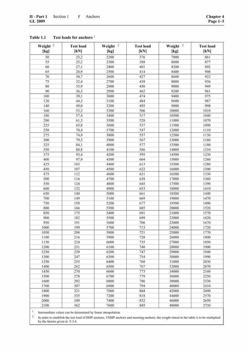
Table 1.1 Test loads for anchors 1
Weight 2 [kg]
Test load [kN]
Weight 2 [kg]
Test load [kN]
Weight 2 [kg]
Test load [kN]
50 23,2 2200 376 7800 861 55 25,2 2300 388 8000 877 60 27,1 2400 401 8200 892 65 28,9 2500 414 8400 908 70 30,7 2600 427 8600 922 75 32,4 2700 438 8800 936 80 33,9 2800 450 9000 949 90 36,3 2900 462 9200 961
100 39,1 3000 474 9400 975 120 44,3 3100 484 9600 987 140 49,0 3200 495 9800 998 160 53,3 3300 506 10000 1010 180 57,4 3400 517 10500 1040 200 61,3 3500 528 11000 1070 225 65,8 3600 537 11500 1090 250 70,4 3700 547 12000 1110 275 74,9 3800 557 12500 1130 300 79,5 3900 567 13000 1160 325 84,1 4000 577 13500 1180 350 88,8 4100 586 14000 1210 375 93,4 4200 595 14500 1230 400 97,9 4300 604 15000 1260 425 103 4400 613 15500 1280 450 107 4500 622 16000 1300 475 112 4600 631 16500 1330 500 116 4700 638 17000 1360 550 124 4800 645 17500 1390 600 132 4900 653 18000 1410 650 140 5000 661 18500 1440 700 149 5100 669 19000 1470 750 158 5200 677 19500 1490 800 166 5300 685 20000 1520 850 175 5400 691 21000 1570 900 182 5500 699 22000 1620 950 191 5600 706 23000 1670
1000 199 5700 713 24000 1720 1050 208 5800 721 25000 1770 1100 216 5900 728 26000 1800 1150 224 6000 735 27000 1850 1200 231 6100 740 28000 1900 1250 239 6200 747 29000 1940 1300 247 6300 754 30000 1990 1350 255 6400 760 31000 2030 1400 262 6500 767 32000 2070 1450 270 6600 773 34000 2160 1500 278 6700 779 36000 2250 1600 292 6800 786 38000 2330 1700 307 6900 794 40000 2410 1800 321 7000 804 42000 2490 1900 335 7200 818 44000 2570 2000 349 7400 832 46000 2650 2100 362 7600 845 48000 2730
1 Intermediate values can be determined by linear interpolation. 2 In order to establish the test load of HHP anchors, VHHP anchors and mooring anchors, the weight stated in the table is to be multiplied
by the factors given in F.3.4.
II - Part 1 GL 2009
Section 1 Anchors Chapter 4Page 1–3
F
– anchors with very high holding power (VHHP): a weight equal to 2,0 times the actual weight of the anchor
– mooring anchors: a weight equal to 1.33 times the actual weight, unless specified otherwise
3.5 After the load test, anchors are to be submit-ted to the Surveyor for verification of their delivery condition. Verification comprises visual inspection according to 2. as well as surface crack testing. In case of anchors of composite construction the freedom of movement of the arms is to be demonstrated.
G. Marking
1. Anchors which have fulfilled the test condi-tions are to be marked by the manufacturer as follows:
– manufacturer's symbol
– number of the GL test certificate
– month and year of test
– total weight
– weight of stock (in the case of stocked anchors)
– the letters HHP in the case of anchors with high holding power
– the letters VHHP in the case of anchors with very high holding power
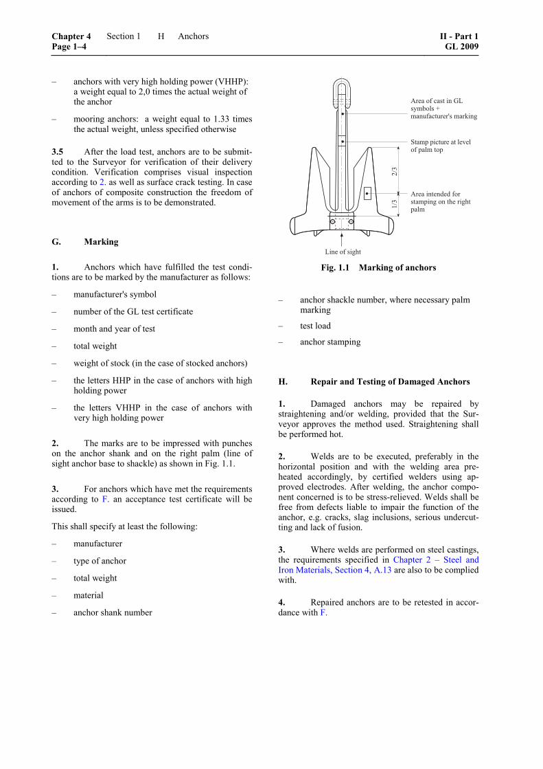
2. The marks are to be impressed with punches on the anchor shank and on the right palm (line of sight anchor base to shackle) as shown in Fig. 1.1.
3. For anchors which have met the requirements according to F. an acceptance test certificate will be issued.
This shall specify at least the following:
– manufacturer
– type of anchor
– total weight
– material
– anchor shank number
���
���
����� ����
������������ ��������������������
������� ����� ����� ������������� �������
�������������!����������
Fig. 1.1 Marking of anchors
– anchor shackle number, where necessary palm marking
– test load
– anchor stamping
H. Repair and Testing of Damaged Anchors
1. Damaged anchors may be repaired by straightening and/or welding, provided that the Sur-veyor approves the method used. Straightening shall be performed hot.
2. Welds are to be executed, preferably in the horizontal position and with the welding area pre-heated accordingly, by certified welders using ap-proved electrodes. After welding, the anchor compo-nent concerned is to be stress-relieved. Welds shall be free from defects liable to impair the function of the anchor, e.g. cracks, slag inclusions, serious undercut-ting and lack of fusion.
3. Where welds are performed on steel castings, the requirements specified in Chapter 2 – Steel and Iron Materials, Section 4, A.13 are also to be complied with.
4. Repaired anchors are to be retested in accor-dance with F.
Chapter 4 Page 1–4
Section 1 Anchors II - Part 1GL 2009
H
Section 2
Chain Cables and Accessories
A. Anchor Chain Cables and Accessories
1. General rules
1.1 Scope
These Rules are applicable to the materials, design, manufacture and testing of stud link chain cables and accessories for ships. Where short-linked studless chain cables are used in exceptional cases with GL's approval, they shall comply with a recognized standard. For connecting components fixed to the anchor Section 1 is applicable.
1.2 Chain cable grades
Depending on the nominal strength of the steel used to manufacture the chain cable, stud link chain cables are classified into the grades GL-K1, GL-K2 and GL-K3.
Regarding chain cable grades GL-R3, GL-R3S and GL-R4 the Rules IV – Industrial Services, Part 6 – Offshore Technology, Chapter 2 – Mobile Offshore Units, Section 8, C.4. are to be observed and applied.
1.3 Approval of chain cable manufacturers
1.3.1 Anchor chain cables and accessories may only be manufactured by works approved by GL.
1.3.2 For non-standard accessories, the drawings shall be submitted to GL for approval.
2. Chain cable materials
2.1 Scope
These Rules are applicable to rolled steels, forgings and cast steels for the manufacture of anchor chain cables and accessories.
2.2 Requirements to be met by material manu-facturers
2.2.1 All materials for the manufacture of anchor chain cables and accessories may only be supplied by manufacturers approved by GL. Approval tests shall be conducted for this purpose.
2.2.2 The manufacturers of the materials or the anchor chain cables shall submit to GL specifications of the materials to be used.
2.2.3 The material specification shall contain all the information required for its evaluation, such as the
method of manufacture, method of deoxidation, nomi-nal chemical composition, method of heat treatment and mechanical properties.
2.2.4 Rolled products, forgings and castings in-tended for the manufacture of anchor chain cables and accessories shall meet the required values for the me-chanical properties according to Table 2.2.
2.3 Rolled steel bars
2.3.1 Manufacturing process
The steels shall be manufactured by the basic oxygen, electric furnace or open-hearth process. Grade GL-K1 chain cable steel shall be killed before pouring, while all other grades shall be killed and fine grain treated.
2.3.2 Condition of supply
Unless otherwise specified, the steels shall be supplied in rolled condition.
2.3.3 Chemical composition
Rolled steel bars are to be supplied with a certificate of the manufacturer about the chemical composition of each heat.
The chemical composition of the steels shall conform to the data in Table 2.1.
2.3.4 Testing of mechanical properties
The mechanical tests shall be performed at the chain cable manufacturer's premises.
At the request of the chain cable manufacturer, the mechanical testing of the steel bars may be carried out at the rolling mill; the test sections shall be in a heat-treated condition corresponding to that of the finished chain cable. In this case, the requirements specified in Table 2.1 shall be met.
2.3.5 Dimensional tolerances of rolled steels
The diameter and oval shape of rolled steels shall lie within the permitted dimensional tolerances shown in Table 2.3.
2.3.6 External and internal condition
The material shall be free from internal and surface defects which have more than an insignificant adverse effect on their proper working and use. Surface defects may be removed by grinding provided that the permit-ted tolerances are not exceeded.
II - Part 1 GL 2009
Section 2 Chain Cables and Accessories Chapter 4Page 2–1
A
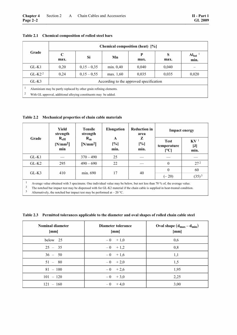
Table 2.1 Chemical composition of rolled steel bars
Chemical composition (heat) [%] Grade C
max. Si Mn P
max. S
max. Altot 1 min.
GL-K1 0,20 0,15 – 0,35 min. 0,40 0,040 0,040 –
GL-K2 2 0,24 0,15 – 0,55 max. 1,60 0,035 0,035 0,020
GL-K3 According to the approved specification 1 Aluminium may be partly replaced by other grain refining elements. 2 With GL approval, additional alloying constituents may be added.
Table 2.2 Mechanical properties of chain cable materials
Impact energy
Grade
Yield strength
ReH [N/mm2]
min
Tensile strength
Rm [N/mm2]
Elongation A
[%] min.
Reduction in area
Z [%] min.
Test temperature
[°C]
KV 1 [J]
min.
GL-K1 –– 370 – 490 25 –– –– –– GL-K2 295 490 – 690 22 –– 0 27 2
0 60 GL-K3 410 min. 690 17 40
(– 20) (35) 3 1 Average value obtained with 3 specimens. One individual value may be below, but not less than 70 % of, the average value. 2 The notched bar impact test may be dispensed with for GL-K2 material if the chain cable is supplied in heat-treated condition. 3 Alternatively, the notched bar impact test may be performed at – 20 °C.
Table 2.3 Permitted tolerances applicable to the diameter and oval shapes of rolled chain cable steel
Nominal diameter [mm]
Diameter tolerance [mm]
Oval shape (dmax – dmin) [mm]
below 25 – 0 + 1,0 0,6
25 – 35 – 0 + 1,2 0,8
36 – 50 – 0 + 1,6 1,1
51 – 80 – 0 + 2,0 1,5
81 – 100 – 0 + 2,6 1,95
101 – 120 – 0 + 3,0 2,25
121 – 160 – 0 + 4,0 3,00
Chapter 4 Page 2–2
Section 2 Chain Cables and Accessories II - Part 1GL 2009
A
2.3.7 Identification of the material
The manufacturer shall have an identification system which enables the material to be traced back to its manufacture.
2.3.8 Testing
2.3.8.1 For the mechanical tests, the steel bars shall be sorted into heats and sizes and grouped into test batches weighing 50 t max. One test section shall be taken from each test batch for the tests stated in 2.3.8.3 and 2.3.8.4.
Before the test specimens are prepared, the test sec-tions shall be subjected to the heat treatment intended for the finished chain cable, see Table 2.4. The details of the heat treatment shall be established by the manu-facturer.
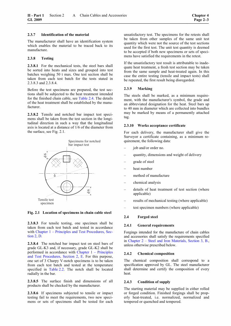
2.3.8.2 Tensile and notched bar impact test speci-mens shall be taken from the test section in the longi-tudinal direction in such a way that the longitudinal axis is located at a distance of 1/6 of the diameter from the surface, see Fig. 2.1.
���
���
�
������� ��� ���������� ���� ����
������ ����������
Fig. 2.1 Location of specimens in chain cable steel
2.3.8.3 For tensile testing, one specimen shall be taken from each test batch and tested in accordance with Chapter 1 – Principles and Test Procedures, Sec-tion 2, D.
2.3.8.4 The notched bar impact test on steel bars of grade GL-K3 and, if necessary, grade GL-K2 shall be performed in accordance with Chapter 1 – Principles and Test Procedures, Section 2, E. For this purpose, one set of 3 Charpy V-notch specimens is to be taken from each test batch and tested at the temperature specified in Table 2.2. The notch shall be located radially in the bar.
2.3.8.5 The surface finish and dimensions of all products shall be checked by the manufacturer.
2.3.8.6 If specimens subjected to tensile or impact testing fail to meet the requirements, two new speci-mens or sets of specimens shall be tested for each
unsatisfactory test. The specimens for the retests shall be taken from other samples of the same unit test quantity which were not the source of the test sections used for the first test. The unit test quantity is deemed to be accepted if both new specimens or sets of speci-mens have satisfied the requirements in the retest.
If the unsatisfactory test result is attributable to inade-quate heat treatment, a fresh test section may be taken from the same sample and heat-treated again. In this case the entire testing (tensile and impact tests) shall be repeated, the first result being disregarded.
2.3.9 Marking
The steels shall be marked, as a minimum require-ment, with the manufacturer's symbol, the grade and an abbreviated designation for the heat. Steel bars up to 40 mm in diameter which are collected into bundles may be marked by means of a permanently attached tag.
2.3.10 Works acceptance certificate
For each delivery, the manufacturer shall give the Surveyor a certificate containing, as a minimum re-quirement, the following data:
– job and/or order no.
– quantity, dimensions and weight of delivery
– grade of steel
– heat number
– method of manufacture
– chemical analysis
– details of heat treatment of test section (where applicable)
– results of mechanical testing (where applicable)
– test specimen numbers (where applicable)
2.4 Forged steel
2.4.1 General requirements
Forgings intended for the manufacture of chain cables and accessories shall satisfy the requirements specified in Chapter 2 – Steel and Iron Materials, Section 3, B., unless otherwise prescribed below.
2.4.2 Chemical composition
The chemical composition shall correspond to a specification approved by GL. The steel manufacturer shall determine and certify the composition of every heat.
2.4.3 Condition of supply
The starting material may be supplied in either rolled or forged condition. Finished forgings shall be prop-erly heat-treated, i.e. normalized, normalized and tempered or quenched and tempered.
II - Part 1 GL 2009
Section 2 Chain Cables and Accessories Chapter 4Page 2–3
A
2.4.4 Mechanical properties
Unless other requirements are prescribed according to the specification, the requirements shown in Table 2.2 shall, as a minimum requirement, be met after heat treatment has been carried out.
2.4.5 Mechanical tests
For the preparation of test specimens, forgings of approximately the same size which originate from the same heat and heat treatment batch shall be grouped into a test batch. One tensile test specimen and one set of 3 Charpy V-notch specimens shall be taken from every test batch and tested. For the location of the specimens, please refer to 2.3.8.2 and Fig. 2.1.
2.5 Steel castings
2.5.1 General requirements
Steel castings intended for the manufacture of chain cables and accessories shall satisfy the requirements specified in Chapter 2 – Steel and Iron Materials, Section 4, B., unless otherwise prescribed below.
2.5.2 Chemical composition
The chemical composition shall correspond to a speci-fication approved by GL. The steel manufacturer shall determine and certify the composition of every heat.
2.5.3 Heat treatment
All steel castings shall be properly heat treated, i.e. normalized or quenched and tempered.
2.5.4 Mechanical properties
Unless other requirements are prescribed according to the specification, the requirements shown in Table 2.2 shall be met as a minimum requirement.
2.5.5 Mechanical tests
For the preparation of test specimens, castings of approximately the same size which originate from the same heat and heat treatment batch shall be grouped into a test batch. One tensile test specimen and one set of 3 Charpy V-notch specimens shall be taken from every test batch and tested.
2.6 Material for the studs of chain links
The studs of chain links shall be made of a type of steel which corresponds to the chain cable or of unal-loyed rolled, forged or cast low-carbon steels. The use of other materials such as grey or nodular cast iron is not permitted.
3. Construction and manufacture
3.1 Method of manufacture
3.1.1 Stud link chain cables should preferably be manufactured by flash butt welding using rolled steel
bars of grades GL-K1, GL-K2 or GL-K3, see 2. Manufacture of the links by drop forging or steel cast-ing is also permitted. On request, pressure butt weld-ing may also be approved for studless chain cables made of grades GL-K1 and GL-K2, provided that the nominal diameter of the chain cable does not exceed 26 mm.
3.1.2 Accessories such as shackles, swivels and swivel shackles shall be forged or cast in steel of at least grade GL-K2. Welded constructions are subject to GL approval.
3.2 Construction
Anchor chain cables shall be manufactured according to a standard recognized by GL, e.g. ISO 1704. Con-ventional constructions of chain cable links are shown in Figs. 2.4, 2.5 and 2.6. A length of chain cable shall comprise an odd number of links.
If the construction does not comply with this provision or if accessories are to be of welded construction, drawings giving full details of the manufacturing process and the method of heat treatment shall be submitted to GL for approval.
3.3 Heat treatment
Depending on the grade of steel, chain cables shall be supplied in one of the conditions specified in Table 2.4. Heat treatments shall always be performed before the tests at proof and breaking loads.
Table 2.4 Heat treatment of chain cables
Grade Condition of supply
GL-K1 (GL-K2) 1
Untreated or normalized after welding
GL-K2 GL-K3
Normalized, normalized and tempered or quenched and tempered
1 Chain cables made of grade GL-K2 steel shall generally be normalized. GL may waive this stipulation if it is proved by means of an approval test that the chain cables meet the requirements. An extended scope of testing may be prescribed for such chain cables.
3.4 Mechanical properties
The mechanical properties of the finished chain cable and accessories, i.e. tensile strength, elongation, re-duction in area and impact energy, shall meet the requirements shown in Table 2.2.
3.5 Requirements applicable to proof and breaking loads
Chain cables and accessories shall be manufactured in such a way that they withstand the proof and breaking loads specified for the respective grade of steel in Table 2.7.
Chapter 4 Page 2–4
Section 2 Chain Cables and Accessories II - Part 1GL 2009
A
3.6 Freedom from defects
3.6.1 All individual parts shall have a high-quality surface consistent with the method of manufacture and free from cracks, notches, inclusions and other defects which restrict the use of the product. The flashes pro-duced by upsetting and forging shall be properly re-moved, see 3.7.2.
3.6.2 Insignificant surface defects may be levelled by grinding so as to leave a gentle transition to the surrounding surface. Outside the bends of the links, localized grinding up to a depth of 5 % of the nominal diameter is permitted.
3.7 Dimensions and dimensional tolerances
3.7.1 The dimensions of shackles and swivels shall conform to a recognized standard. Conventional con-structions are shown in Figs. 2.7 to 2.10.
3.7.2 The following tolerances are acceptable for links:
– Diameter in the area of the link bend (crown)
Up to 40 mm nominal diameter: –1 mm
Over 40 up to 84 mm nominal diameter: –2 mm
Over 84 up to 122 mm nominal diameter: –3 mm
Over 122 mm nominal diameter: –4 mm
The plus tolerance may be up to 5 % of the nominal diameter. The link bend cross section may not have any negative tolerance.
– Diameter, measured at points outside the link bend (crown):
The diameter may not have a negative tolerance. The plus tolerance may be up to 5 % of the nominal diameter. The plus tolerance in the area of the reinforcement is subject to the chain cable manufacturer’s production specification which shall be approved by GL. (The plus tolerance shall not be more than 8 % of the nominal di-ameter).
– The maximum tolerance for the chain cable measured over a length of 5 links may be up to + 2,5 % but shall not assume a negative value. This applies to chain cables under 10 % initial load after proof loading.
– All other dimensions are subject to a manufac-turing tolerance of up to ± 2,5 %, provided that all parts of the chain cable fit together properly.
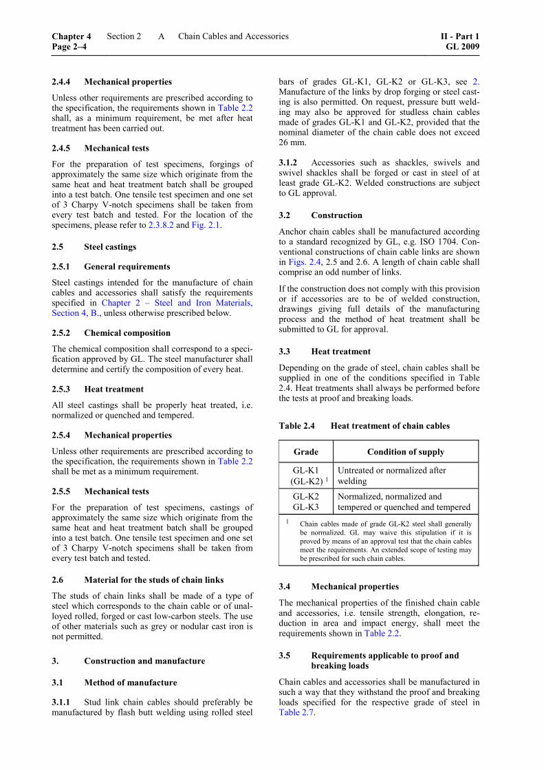
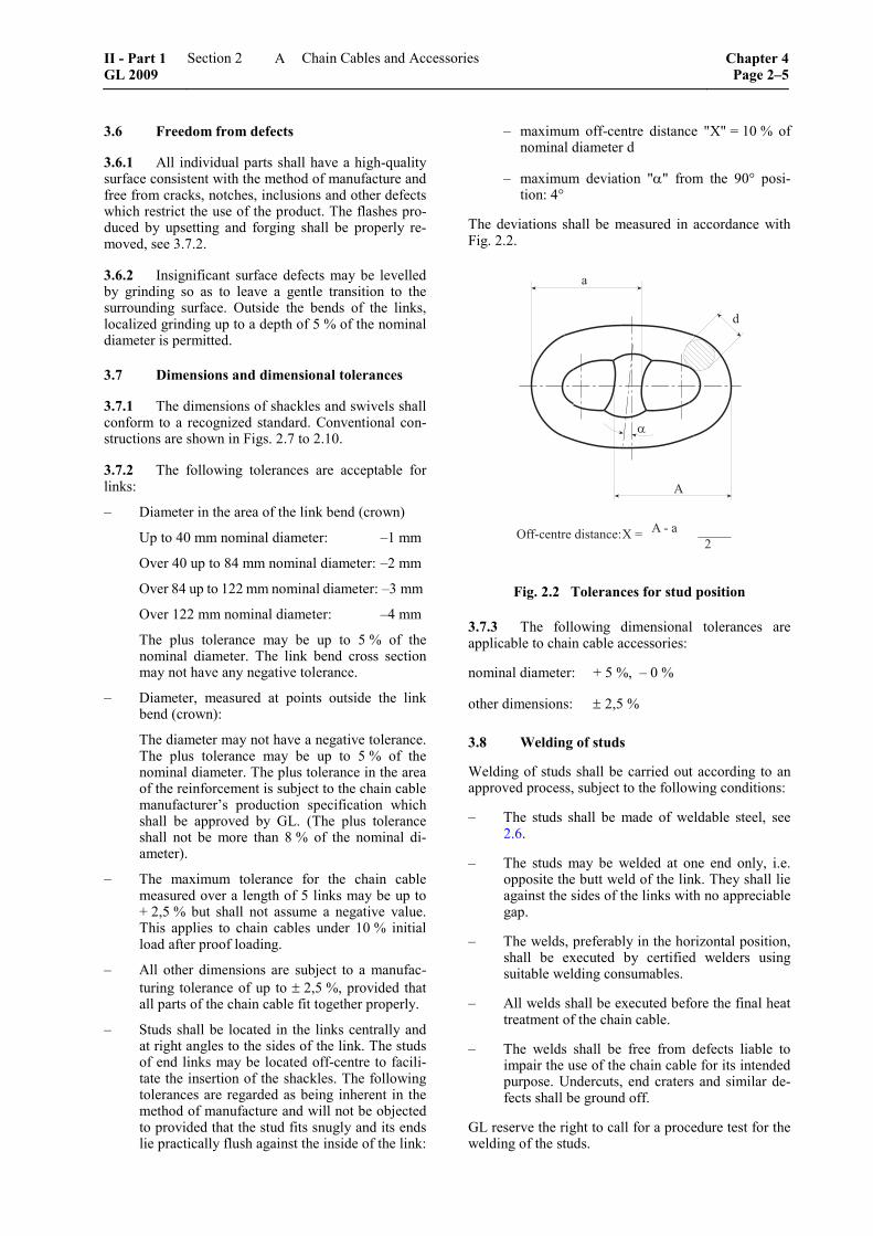
– Studs shall be located in the links centrally and at right angles to the sides of the link. The studs of end links may be located off-centre to facili-tate the insertion of the shackles. The following tolerances are regarded as being inherent in the method of manufacture and will not be objected to provided that the stud fits snugly and its ends lie practically flush against the inside of the link:
– maximum off-centre distance "X" = 10 % of nominal diameter d
– maximum deviation "α" from the 90° posi-tion: 4°
The deviations shall be measured in accordance with Fig. 2.2.
�
�
�
�
���������� ��������� � � � � �����
�
Fig. 2.2 Tolerances for stud position
3.7.3 The following dimensional tolerances are applicable to chain cable accessories:
nominal diameter: + 5 %, – 0 %
other dimensions: ± 2,5 %
3.8 Welding of studs
Welding of studs shall be carried out according to an approved process, subject to the following conditions:
– The studs shall be made of weldable steel, see 2.6.
– The studs may be welded at one end only, i.e. opposite the butt weld of the link. They shall lie against the sides of the links with no appreciable gap.
– The welds, preferably in the horizontal position, shall be executed by certified welders using suitable welding consumables.
– All welds shall be executed before the final heat treatment of the chain cable.
– The welds shall be free from defects liable to impair the use of the chain cable for its intended purpose. Undercuts, end craters and similar de-fects shall be ground off.
GL reserve the right to call for a procedure test for the welding of the studs.
II - Part 1 GL 2009
Section 2 Chain Cables and Accessories Chapter 4Page 2–5
A
4. Testing of finished chain cables
4.1 Tests at proof and breaking loads
4.1.1 All chain cables are to be subjected to the following tests in the presence of the Surveyor. For this purpose, the chain cables shall be free from paint and anti-corrosion media. The test pieces shall not break and shall be free from cracks after testing.
4.1.2 Each chain cable length (27,5 m) is to be subjected to a loading test at the proof load appropri-ate to the particular chain cable as shown in Table 2.7, using an approved testing machine.
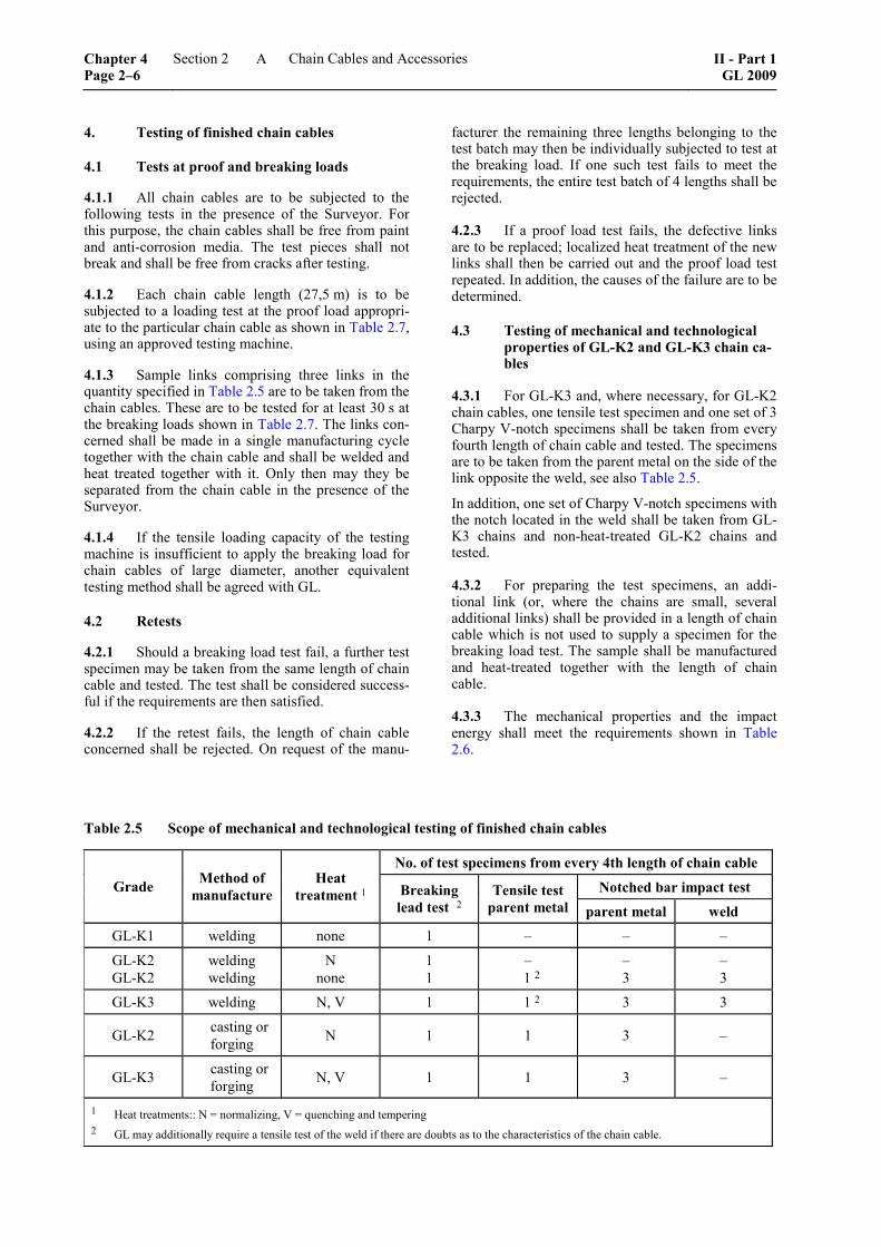
4.1.3 Sample links comprising three links in the quantity specified in Table 2.5 are to be taken from the chain cables. These are to be tested for at least 30 s at the breaking loads shown in Table 2.7. The links con-cerned shall be made in a single manufacturing cycle together with the chain cable and shall be welded and heat treated together with it. Only then may they be separated from the chain cable in the presence of the Surveyor.
4.1.4 If the tensile loading capacity of the testing machine is insufficient to apply the breaking load for chain cables of large diameter, another equivalent testing method shall be agreed with GL.
4.2 Retests
4.2.1 Should a breaking load test fail, a further test specimen may be taken from the same length of chain cable and tested. The test shall be considered success-ful if the requirements are then satisfied.
4.2.2 If the retest fails, the length of chain cable concerned shall be rejected. On request of the manu-
facturer the remaining three lengths belonging to the test batch may then be individually subjected to test at the breaking load. If one such test fails to meet the requirements, the entire test batch of 4 lengths shall be rejected.
4.2.3 If a proof load test fails, the defective links are to be replaced; localized heat treatment of the new links shall then be carried out and the proof load test repeated. In addition, the causes of the failure are to be determined.
4.3 Testing of mechanical and technological properties of GL-K2 and GL-K3 chain ca-bles
4.3.1 For GL-K3 and, where necessary, for GL-K2 chain cables, one tensile test specimen and one set of 3 Charpy V-notch specimens shall be taken from every fourth length of chain cable and tested. The specimens are to be taken from the parent metal on the side of the link opposite the weld, see also Table 2.5.
In addition, one set of Charpy V-notch specimens with the notch located in the weld shall be taken from GL-K3 chains and non-heat-treated GL-K2 chains and tested.
4.3.2 For preparing the test specimens, an addi-tional link (or, where the chains are small, several additional links) shall be provided in a length of chain cable which is not used to supply a specimen for the breaking load test. The sample shall be manufactured and heat-treated together with the length of chain cable.
4.3.3 The mechanical properties and the impact energy shall meet the requirements shown in Table 2.6.
Table 2.5 Scope of mechanical and technological testing of finished chain cables
No. of test specimens from every 4th length of chain cable
Notched bar impact test Grade Method of manufacture
Heat treatment 1 Breaking
lead test 2 Tensile test
parent metal parent metal weld
GL-K1 welding none 1 – – –
GL-K2 GL-K2
welding welding
N none
1 1
– 1 2
– 3
– 3
GL-K3 welding N, V 1 1 2 3 3
GL-K2 casting orforging N 1 1 3 –
GL-K3 casting orforging N, V 1 1 3 –
1 Heat treatments:: N = normalizing, V = quenching and tempering 2 GL may additionally require a tensile test of the weld if there are doubts as to the characteristics of the chain cable.
Chapter 4 Page 2–6
Section 2 Chain Cables and Accessories II - Part 1GL 2009
A
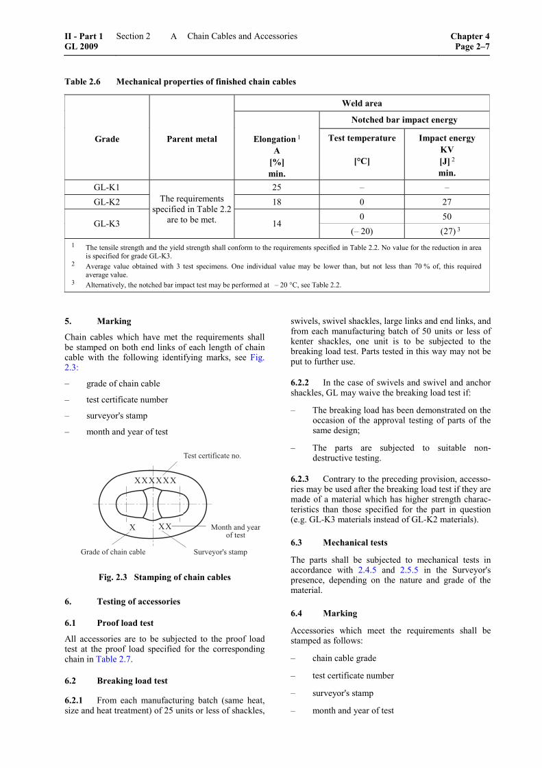
Table 2.6 Mechanical properties of finished chain cables
Weld area
Notched bar impact energy
Grade Parent metal Elongation 1 A
[%] min.
Test temperature
[°C]
Impact energy KV [J] 2 min.
GL-K1 25 – – GL-K2 18 0 27
0 50 GL-K3
The requirements specified in Table 2.2
are to be met. 14 (– 20) (27) 3
1 The tensile strength and the yield strength shall conform to the requirements specified in Table 2.2. No value for the reduction in area is specified for grade GL-K3.
2 Average value obtained with 3 test specimens. One individual value may be lower than, but not less than 70 % of, this required average value.
3 Alternatively, the notched bar impact test may be performed at – 20 °C, see Table 2.2.
5. Marking
Chain cables which have met the requirements shall be stamped on both end links of each length of chain cable with the following identifying marks, see Fig. 2.3:
– grade of chain cable
– test certificate number
– surveyor's stamp
– month and year of test
���� ��������� ���
� �!�"��#� ����$���� �� ���� �����
������
� �� %���� ��� "����� ����
Fig. 2.3 Stamping of chain cables
6. Testing of accessories
6.1 Proof load test
All accessories are to be subjected to the proof load test at the proof load specified for the corresponding chain in Table 2.7.
6.2 Breaking load test
6.2.1 From each manufacturing batch (same heat, size and heat treatment) of 25 units or less of shackles,
swivels, swivel shackles, large links and end links, and from each manufacturing batch of 50 units or less of kenter shackles, one unit is to be subjected to the breaking load test. Parts tested in this way may not be put to further use.
6.2.2 In the case of swivels and swivel and anchor shackles, GL may waive the breaking load test if:
– The breaking load has been demonstrated on the occasion of the approval testing of parts of the same design;
– The parts are subjected to suitable non-destructive testing.
6.2.3 Contrary to the preceding provision, accesso-ries may be used after the breaking load test if they are made of a material which has higher strength charac-teristics than those specified for the part in question (e.g. GL-K3 materials instead of GL-K2 materials).
6.3 Mechanical tests
The parts shall be subjected to mechanical tests in accordance with 2.4.5 and 2.5.5 in the Surveyor's presence, depending on the nature and grade of the material.
6.4 Marking
Accessories which meet the requirements shall be stamped as follows:
– chain cable grade
– test certificate number
– surveyor's stamp
– month and year of test
II - Part 1 GL 2009
Section 2 Chain Cables and Accessories Chapter 4Page 2–7
A
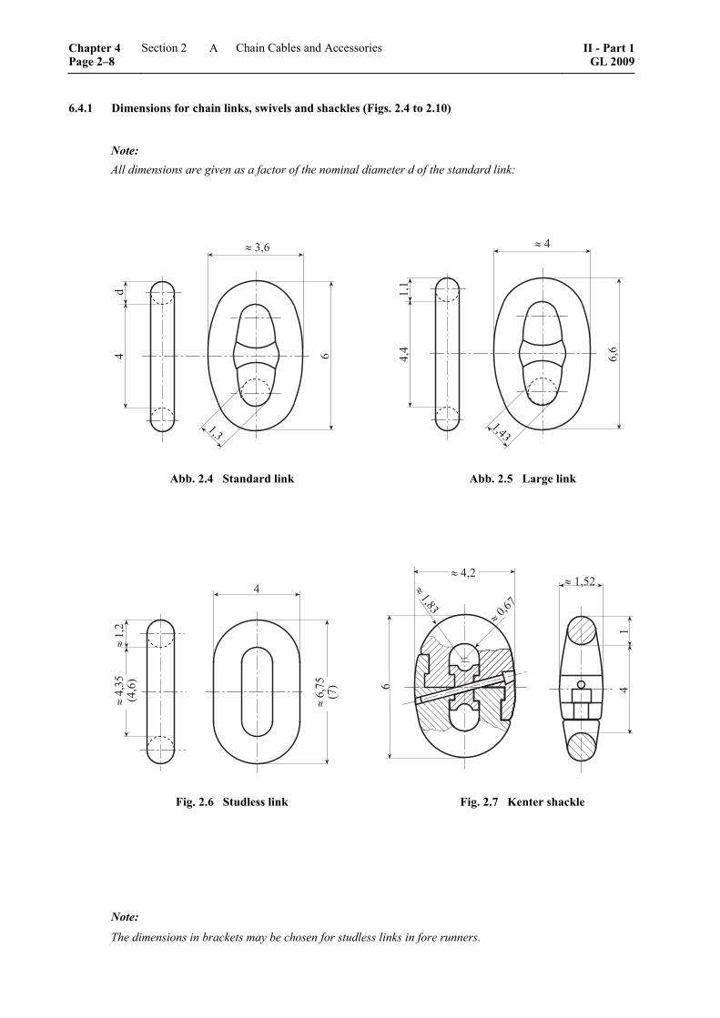
6.4.1 Dimensions for chain links, swivels and shackles (Figs. 2.4 to 2.10)
Note: All dimensions are given as a factor of the nominal diameter d of the standard link:
�& �
� '(�
)('
)()
&(&
�(�
��&
)(&'
Abb. 2.4 Standard link Abb. 2.5 Large link
&
� )(�
� &('*
+&(�,
� �(-*
+-,
� )(*�� &(�
� &)
� .(�-
� )(/'
Fig. 2.6 Studless link Fig. 2.7 Kenter shackle
Note:
The dimensions in brackets may be chosen for studless links in fore runners.
Chapter 4 Page 2–8
Section 2 Chain Cables and Accessories II - Part 1GL 2009
A
� .(� � )('
&
� -()
�(/
� .(& 0
� )('
� '(&
� )(�
� .(/
� .(�
� .(*
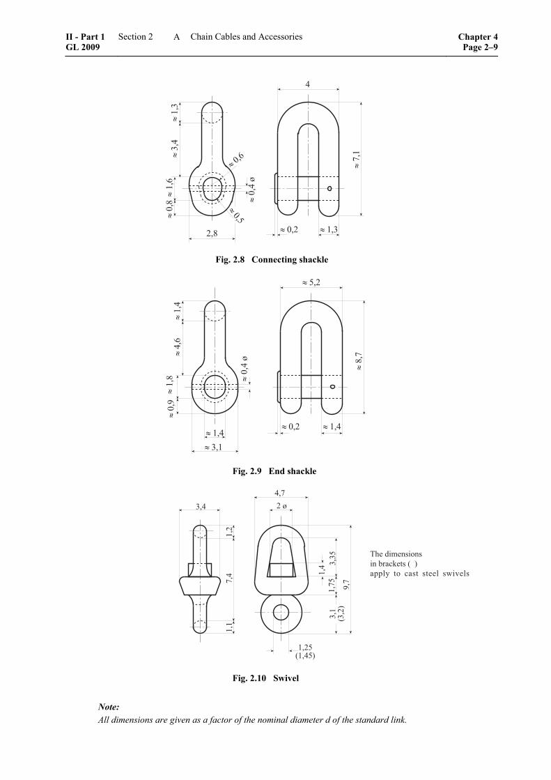
Fig. 2.8 Connecting shackle
� )(&� .(� � )(&
� *(�
� /(-
� '()
� .(& 0
� )(&
� &(�
� )(/
� .(1
Fig. 2.9 End shackle
)()
&(-
� 0
)(& '(
'*)(-* 1(-
'()
+'(�,
)(�*+)(&*,
)(�
-(&
'(&
��� �������� ����2��� + ,����" �� ���� ����� �3!���
Fig. 2.10 Swivel
Note: All dimensions are given as a factor of the nominal diameter d of the standard link.
II - Part 1 GL 2009
Section 2 Chain Cables and Accessories Chapter 4Page 2–9
A
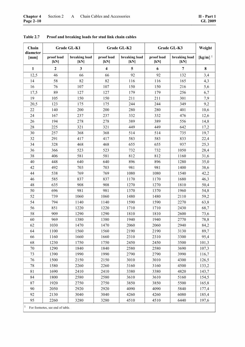
Table 2.7 Proof and breaking loads for stud link chain cables
Grade GL-K1 Grade GL-K2 Grade GL-K3 Chain diameter
[mm] proof load [kN]
breaking load [kN]
proof load [kN]
breaking load[kN]
proof load [kN]
breaking load [kN]
Weight
[kg/m] 1
1 2 3 4 5 6 7 8 12,5 46 66 66 92 92 132 3,4 14 58 82 82 116 116 165 4,3 16 76 107 107 150 150 216 5,6 17,5 89 127 127 179 179 256 6,7 19 105 150 150 211 211 301 7,9 20,5 123 175 175 244 244 349 9,2 22 140 200 200 280 280 401 10,6 24 167 237 237 332 332 476 12,6 26 194 278 278 389 389 556 14,8 28 225 321 321 449 449 642 17,2 30 257 368 368 514 514 735 19,7 32 291 417 417 583 583 833 22,4 34 328 468 468 655 655 937 25,3 36 366 523 523 732 732 1050 28,4 38 406 581 581 812 812 1160 31,6 40 448 640 640 896 896 1280 35,0 42 492 703 703 981 981 1400 38,6 44 538 769 769 1080 1080 1540 42,2 46 585 837 837 1170 1170 1680 46,3 48 635 908 908 1270 1270 1810 50,4 50 696 981 981 1370 1370 1960 54,8 52 739 1060 1060 1480 1480 2110 59,2 54 794 1140 1140 1590 1590 2270 63,8 56 851 1220 1220 1710 1710 2430 68,7 58 909 1290 1290 1810 1810 2600 73,6 60 969 1380 1380 1940 1940 2770 78,8 62 1030 1470 1470 2060 2060 2940 84,2 64 1100 1560 1560 2190 2190 3130 89,7 66 1160 1660 1660 2310 2310 3300 95,4 68 1230 1750 1750 2450 2450 3500 101,3 70 1290 1840 1840 2580 2580 3690 107,3 73 1390 1990 1990 2790 2790 3990 116,7 76 1500 2150 2150 3010 3010 4300 126,5 78 1580 2260 2260 3160 3160 4500 133,2 81 1690 2410 2410 3380 3380 4820 143,7 84 1800 2580 2580 3610 3610 5160 154,5 87 1920 2750 2750 3850 3850 5500 165,8 90 2050 2920 2920 4090 4090 5840 177,4 92 2130 3040 3040 4260 4260 6080 185,4 95 2260 3280 3280 4510 4510 6440 197,6
1 For footnotes, see end of table.
Chapter 4 Page 2–10
Section 2 Chain Cables and Accessories II - Part 1GL 2009
A
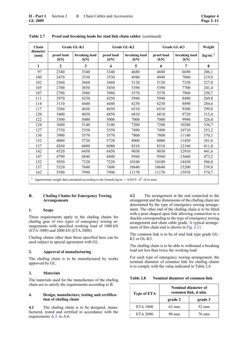
Table 2.7 Proof and breaking loads for stud link chain cables (continued)
Grade GL-K1 Grade GL-K2 Grade GL-K3 Chain diameter
[mm] proof load [kN]
breaking load [kN]
proof load [kN]
breaking load[kN]
proof load [kN]
breaking load [kN]
Weight
[kg/m] 1
1 2 3 4 5 6 7 8 97 2340 3340 3340 4680 4680 6690 206,1
100 2470 3530 3530 4940 4940 7060 219,0 102 2560 3660 3660 5120 5120 7320 227,8 105 2700 3850 3850 5390 5390 7700 241,4 107 2790 3980 3980 5570 5570 7960 250,7 111 2970 4250 4250 5940 5940 8480 269,8 114 3110 4440 4440 6230 6230 8890 284,6 117 3260 4650 4650 6510 6510 9300 299,8 120 3400 4850 4850 6810 6810 9720 315,4 122 3500 5000 5000 7000 7000 9990 326,0 124 3600 5140 5140 7200 7200 10280 336,7 127 3750 5350 5350 7490 7490 10710 353,2 130 3900 5570 5570 7800 7800 11140 370,1 132 4000 5720 5720 8000 8000 11420 381,6 137 4260 6080 6080 8510 8510 12160 411,0 142 4520 6450 6450 9030 9030 12910 441,6 147 4790 6840 6840 9560 9560 13660 473,2 152 5050 7220 7220 10100 10100 14430 506,0 157 5320 7600 7600 10640 10640 15200 539,8 162 5590 7990 7990 11170 11170 15970 574,7
1 Approximate weight data calculated according to the formula kg/m = 0,0219 ⋅ d2 (d in mm).
B. Chafing Chains for Emergency Towing Arrangements
1. Scope
These requirements apply to the chafing chains for chafing gear of two types of emergency towing ar-rangements with specified working load of 1000 kN (ETA 1000) and 2000 kN (ETA 2000).
Chafing chains other than those specified here can be used subject to special agreement with GL.
2. Approval of manufacturing
The chafing chain is to be manufactured by works approved by GL.
3. Materials
The materials used for the manufacture of the chafing chain are to satisfy the requirements according to B.
4. Design, manufacture, testing and certifica-tion of chafing chain
4.1 The chafing chain is to be designed, manu-factured, tested and certified in accordance with the requirements A.3. to A.6.
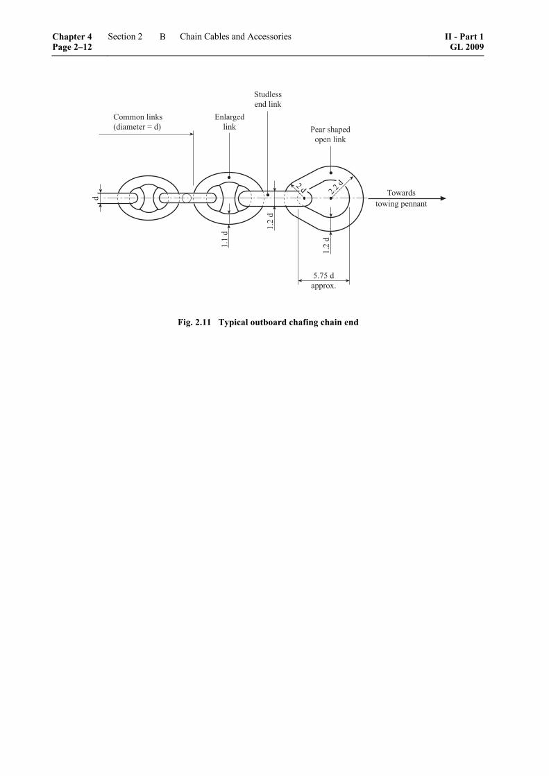
4.2 The arrangement at the end connected to the strongpoint and the dimensions of the chafing chain are determined by the type of emergency towing arrange-ment. The other end of the chafing chain is to be fitted with a pear-shaped open link allowing connection to a shackle corresponding to the type of emergency towing arrangement and chain cable grade. A typical arrange-ment of this chain end is shown in Fig. 2.11.
The common link is to be of stud link type grade GL-K2 or GL-K3.
The chafing chain is to be able to withstand a breaking load not less than twice the working load.
For each type of emergency towing arrangement, the nominal diameter of common link for chafing chains is to comply with the value indicated in Table 2.8
Table 2.8 Nominal diameter of common link
Nominal diameter of common link, d min. Type of ETA
grade 2 grade 3
ETA 1000 62 mm 52 mm
ETA 2000 90 mm 76 mm
II - Part 1 GL 2009
Section 2 Chain Cables and Accessories Chapter 4Page 2–11
B
4��� ��2�+������ � �,
�
)�) �
)�� �
)�� �
*�-* ������5�
6����7����2
�� �������� ��2
8��� ���������� ��2
��3������3�7 �������
��� �� �
Fig. 2.11 Typical outboard chafing chain end
Chapter 4 Page 2–12
Section 2 Chain Cables and Accessories II - Part 1GL 2009
B
Section 3
Wire Ropes
A. Scope
These Rules apply to wire ropes for use as hawsers (towlines, mooring lines) and as standing and running rigging for cargo handling gear and other lifting tackle on board sea-going vessels.
B. Requirements to be Met by the Manufac-turers of Wire Ropes
1. With regard to their production and quality control, wire rope manufacturers shall meet the re-quirements stated in Chapter 1 – Principles and Test Procedures, Section 1, C. and shall be approved by GL.
2. Applications for approval are to be submitted to GL in writing with a description containing at least the following details:
– type, composition and strengths of the ropes concerned
– manufacturing facilities
– testing equipment: copies of the last calibration reports on the testing machines are to be at-tached
By a works inspection, the manufacturer shall demon-strate the availability of the equipment necessary for the proper manufacture and testing of wire ropes. GL reserve the right to call for a preliminary test of suit-ability to be carried out on samples of the rope.
3. If the wire rope manufacturer wishes to be approved by GL for the independent testing of wire ropes, this shall also be applied for. GL will allocate to the manufacturer a special identification number if the conditions for approval stated in 1. and 2. are satisfied.
C. Manufacture
1. The ropes shall conform to recognized na-tional 1 or international standards 2, and should, wher-ever possible, comply with Table 3.1. Ropes of a dif-ferent construction and ropes with high nominal
–––––––––––––– 1 See DIN 3057 to DIN 3060 and DIN 3064 to DIN 3066. 2 See ISO 2408.
breaking strengths, e.g. 1960 N/mm2, or containing austenitic stainless steel wires may be approved on application provided that they are suitable for the proposed application.
2. With the exception of wire ropes made of austenitic stainless steel wires, wire ropes shall nor-mally be manufactured from individually galvanized wires. The use of ungalvanized wires requires the special consent of GL.
D. Requirements Applied to Wire Ropes
1. Nominal breaking strength
Wire ropes shall have the nominal breaking strengths of 1570 and 1770 N/mm2 specified in Table 3.1. These values shall not be exceeded by more than the values shown in Table 3.2.
2. Ductility
Individual wires shall possess sufficient ductility, measured by their ability to withstand a fixed number of reverse bends and/or twists without starting to crack. These requirements are regarded as fulfilled if the values specified in DIN EN 10264, or in an equiv-alent standard recognized by GL are achieved.
3. Tolerance on diameter
The tolerance on the diameter of rope wires shall lie within the limits specified in recognized standards, e.g. in DIN EN 10264.
4. Galvanizing method
Hawsers and standing rigging shall be manufactured from fully galvanized wires. Normally galvanized wires may be used for all other ropes. The zinc coating shall conform to the data shown in Table 3.3
E. Testing of Wire Ropes
The following tests are to be performed:
1. Testing the zinc coating
1.1 The specified weight of the zinc coating is to be determined and certified by the manufacturer by chemically stripping the coating and measuring the
II - Part 1 GL 2009
Section 3 Wire Ropes Chapter 4Page 3–1
E
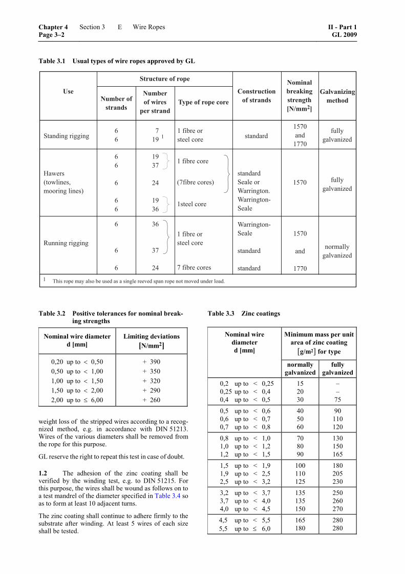
Table 3.1 Usual types of wire ropes approved by GL
����������
� ����
�����������
��� ���������������
� �� �������
���� �� ������ ����
��������������� ��� �������
!��"���#����� ���
����������������
� �
������������� �������
������
���
���������������
���������������������������������������������������������
��
�
��
�
�
�
�!�
"#
�!�
!�
!�
"#
$���������%
�������
��������
�������������
���������
�������������&������� &�������'�����
��� ���������������
&�������'�����
�������
�������
���
���
���
�����������������
(�)��$��)�����*�����������%
+������������
Table 3.2 Positive tolerances for nominal break-ing strengths
Nominal wire diameter d [mm]
Limiting deviations [N/mm2]
0,20 up to < 0,50 0,50 up to < 1,00 1,00 up to < 1,50 1,50 up to < 2,00 2,00 up to ≤ 6,00
+ 390 + 350 + 320 + 290 + 260
weight loss of the stripped wires according to a recog-nized method, e.g. in accordance with DIN 51213. Wires of the various diameters shall be removed from the rope for this purpose.
GL reserve the right to repeat this test in case of doubt.
1.2 The adhesion of the zinc coating shall be verified by the winding test, e.g. to DIN 51215. For this purpose, the wires shall be wound as follows on to a test mandrel of the diameter specified in Table 3.4 so as to form at least 10 adjacent turns.
The zinc coating shall continue to adhere firmly to the substrate after winding. At least 5 wires of each size shall be tested.
Table 3.3 Zinc coatings
Minimum mass per unit area of zinc coating
[g/m2] for type
Nominal wire diameter d [mm]
normally galvanized
fully galvanized
0,2 up to < 0,25 0,25 up to < 0,4 0,4 up to < 0,5
15 20 30
– –
75
0,5 up to < 0,6 0,6 up to < 0,7 0,7 up to < 0,8
40 50 60
90 110 120
0,8 up to < 1,0 1,0 up to < 1,2 1,2 up to < 1,5
70 80 90
130 150 165
1,5 up to < 1,9 1,9 up to < 2,5 2,5 up to < 3,2
100 110 125
180 205 230
3,2 up to < 3,7 3,7 up to < 4,0 4,0 up to < 4,5
135 135 150
250 260 270
4,5 up to < 5,5 5,5 up to ≤ 6,0
165 180
280 280
Chapter 4 Page 3–2
Section 3 Wire Ropes II - Part 1GL 2009
E
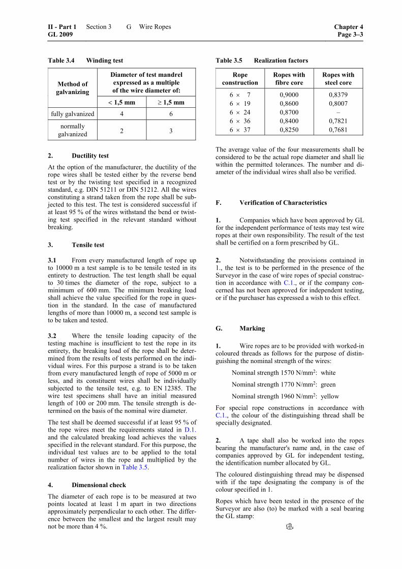
Table 3.4 Winding test
Diameter of test mandrel expressed as a multiple of the wire diameter of:
Method of galvanizing
< 1,5 mm ≥ 1,5 mm
fully galvanized 4 6
normally galvanized 2 3
2. Ductility test
At the option of the manufacturer, the ductility of the rope wires shall be tested either by the reverse bend test or by the twisting test specified in a recognized standard, e.g. DIN 51211 or DIN 51212. All the wires constituting a strand taken from the rope shall be sub-jected to this test. The test is considered successful if at least 95 % of the wires withstand the bend or twist-ing test specified in the relevant standard without breaking.
3. Tensile test
3.1 From every manufactured length of rope up to 10000 m a test sample is to be tensile tested in its entirety to destruction. The test length shall be equal to 30 times the diameter of the rope, subject to a minimum of 600 mm. The minimum breaking load shall achieve the value specified for the rope in ques-tion in the standard. In the case of manufactured lengths of more than 10000 m, a second test sample is to be taken and tested.
3.2 Where the tensile loading capacity of the testing machine is insufficient to test the rope in its entirety, the breaking load of the rope shall be deter-mined from the results of tests performed on the indi-vidual wires. For this purpose a strand is to be taken from every manufactured length of rope of 5000 m or less, and its constituent wires shall be individually subjected to the tensile test, e.g. to EN 12385. The wire test specimens shall have an initial measured length of 100 or 200 mm. The tensile strength is de-termined on the basis of the nominal wire diameter.
The test shall be deemed successful if at least 95 % of the rope wires meet the requirements stated in D.1. and the calculated breaking load achieves the values specified in the relevant standard. For this purpose, the individual test values are to be applied to the total number of wires in the rope and multiplied by the realization factor shown in Table 3.5.
4. Dimensional check
The diameter of each rope is to be measured at two points located at least 1 m apart in two directions approximately perpendicular to each other. The differ-ence between the smallest and the largest result may not be more than 4 %.
Table 3.5 Realization factors
Rope construction
Ropes with fibre core
Ropes with steel core
6 × 7 6 × 19 6 × 24 6 × 36 6 × 37
0,9000 0,8600 0,8700 0,8400 0,8250
0,8379 0,8007
– 0,7821 0,7681
The average value of the four measurements shall be considered to be the actual rope diameter and shall lie within the permitted tolerances. The number and di-ameter of the individual wires shall also be verified.
F. Verification of Characteristics
1. Companies which have been approved by GL for the independent performance of tests may test wire ropes at their own responsibility. The result of the test shall be certified on a form prescribed by GL.
2. Notwithstanding the provisions contained in 1., the test is to be performed in the presence of the Surveyor in the case of wire ropes of special construc-tion in accordance with C.1., or if the company con-cerned has not been approved for independent testing, or if the purchaser has expressed a wish to this effect.
G. Marking
1. Wire ropes are to be provided with worked-in coloured threads as follows for the purpose of distin-guishing the nominal strength of the wires:
Nominal strength 1570 N/mm2: white
Nominal strength 1770 N/mm2: green
Nominal strength 1960 N/mm2: yellow
For special rope constructions in accordance with C.1., the colour of the distinguishing thread shall be specially designated.
2. A tape shall also be worked into the ropes bearing the manufacturer's name and, in the case of companies approved by GL for independent testing, the identification number allocated by GL.
The coloured distinguishing thread may be dispensed with if the tape designating the company is of the colour specified in 1.
Ropes which have been tested in the presence of the Surveyor are also (to) be marked with a seal bearing the GL stamp:
II - Part 1 GL 2009
Section 3 Wire Ropes Chapter 4Page 3–3
G

Section 4
Fibre Ropes
A. Scope
These Rules apply to fibre ropes made from natural and synthetic fibres and used as towlines and mooring lines as well as for cargo handling gear and other lifting tackle on board sea-going vessels.
B. Requirements to be Met by the Manufac-turers of Fibre Ropes
1. With regard to their production and quality control, fibre rope manufacturers shall meet the re-quirements stated in Chapter 1 – Principles and Test Procedures, Section 1, C. and shall be approved by GL.
2. Applications for approval are to be submitted to GL in writing with a description containing at least the following details:
– type, composition and material of the ropes concerned
– manufacturing facilities
– testing equipment: copies of the last calibration reports on the testing machines are to be at-tached
By a work's inspection, the manufacturer shall demon-strate the availability of the equipment necessary for the proper manufacture and testing of fibre ropes. GL reserve the right to call for a preliminary test of suit-ability to be carried out on samples of the rope.
3. If the manufacturer wishes to be approved by GL for the independent testing of fibre ropes (see E.), this shall also be applied for. GL will allocate to the manufacturer a special identification number if the conditions for approval stated in 1. and 2. are satisfied.
C. Manufacture
1. The type, material and structure of the ropes shall conform to a national or international standard recognized by GL and should, wherever possible, comply with Table 4.1. Ropes of a different type may be approved on application provided that they are suitable for the proposed application.
2. Fibre ropes are to be made either of natural fibres (manila, sisal and hemp) or of synthetic fibres (polyamide, polyester and polypropylene). Only new yarns may be used to manufacture the rope. If it is intended to use other materials, their suitability is to be specially demonstrated to GL.
3. Ropes may normally comprise only one ma-terial. Excepted from this rule, and approved by GL, are for example those rope constructions in which the outside layers are reinforced with polyester yarns in order to increase their resistance to abrasion.
The realisation factors for (monofilament) polypro-pylene are applicable to ropes with these outside lay-ers.
D. Required Properties
The properties of fibre ropes shall fulfil the require-ments specified in the standards recognized by GL. These include for example:
DIN-EN 701 and the complementary DIN and ISO standards mentioned therein, see Table 4.1
E. Testing the Breaking Load of Ropes
1. Test method 1
The breaking load of ropes shall normally be deter-mined by applying a tensile test to destruction to entire test sections of the rope in accordance with 3. If such a test is impossible for technical reasons, the breaking load of the rope may be calculated from the tensile values established in testing the individual yarns in accordance with 4. This applies, however, only to those ropes whose maximum loading capacity exceeds 30000 daN and for which reduction factors are given in Table 4.2
2. Sampling
For the purpose of sampling, ropes of the same con-struction, the same material and the same nominal diameter which have been manufactured in an uninter-rupted production run are to be grouped into test
–––––––––––––– 1 See EN 919, and ISO 2307.
II - Part 1 GL 2009
Section 4 Fibre Ropes Chapter 4Page 4–1
E
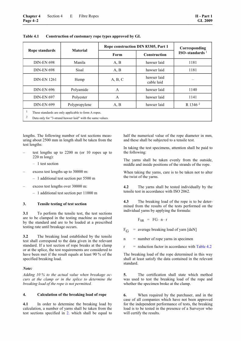
Table 4.1 Construction of customary rope types approved by GL
Rope construction DIN 83305, Part 1 Rope standards Material
Form Construction
Corresponding ISO–standards 1
DIN-EN 698 Manila A, B hawser laid 1181
DIN-EN 698 Sisal A, B hawser laid 1181
DIN-EN 1261 Hemp A, B, C hawser laid cable laid
–
DIN-EN 696 Polyamide A hawser laid 1140
DIN-EN 697 Polyester A hawser laid 1141
DIN-EN 699 Polypropylene A, B hawser laid R 1346 2 1 These standards are only applicable to form A ropes. 2 Data only for "3-strand hawser laid" with the same values.
lengths. The following number of test sections meas-uring about 2500 mm in length shall be taken from the test lengths:
– test lengths up to 2200 m (or 10 ropes up to 220 m long):
– 1 test section
– excess test lengths up to 30000 m:
– 1 additional test section per 5500 m
– excess test lengths over 30000 m:
– 1 additional test section per 11000 m
3. Tensile testing of test section
3.1 To perform the tensile test, the test sections are to be clamped in the testing machine as required by the standard and are to be loaded at a prescribed testing rate until breakage occurs.
3.2 The breaking load established by the tensile test shall correspond to the data given in the relevant standard. If a test section of rope breaks at the clamp or at the splice, the test requirements are considered to have been met if the result equals at least 90 % of the specified breaking load.
Note: Adding 10 % to the actual value when breakage oc-curs at the clamp or in the splice to determine the breaking load of the rope is not permitted.
4. Calculation of the breaking load of rope
4.1 In order to determine the breaking load by calculation, a number of yarns shall be taken from the test sections specified in 2. which shall be equal to
half the numerical value of the rope diameter in mm, and these shall be subjected to a tensile test.
In taking the test specimens, attention shall be paid to the following:
The yarns shall be taken evenly from the outside, middle and inside positions of the strands of the rope.
When taking the yarns, care is to be taken not to alter the twist of the yarns.
4.2 The yarns shall be tested individually by the tensile test in accordance with ISO 2062.
4.3 The breaking load of the rope is to be deter-mined from the results of the tests performed on the individual yarns by applying the formula:
FSR = FG ⋅ n ⋅ r
FG = average breaking load of yarn [daN]
n = number of rope yarns in specimen
r = reduction factor in accordance with Table 4.2
The breaking load of the rope determined in this way shall at least satisfy the data contained in the relevant standard.
5. The certification shall state which method was used to test the breaking load of the rope and whether the specimen broke at the clamp.
6. When required by the purchaser, and in the case of all companies which have not been approved for the independent performance of tests, the breaking load is to be tested in the presence of a Surveyor who will certify the results.
Chapter 4 Page 4–2
Section 4 Fibre Ropes II - Part 1GL 2009
E
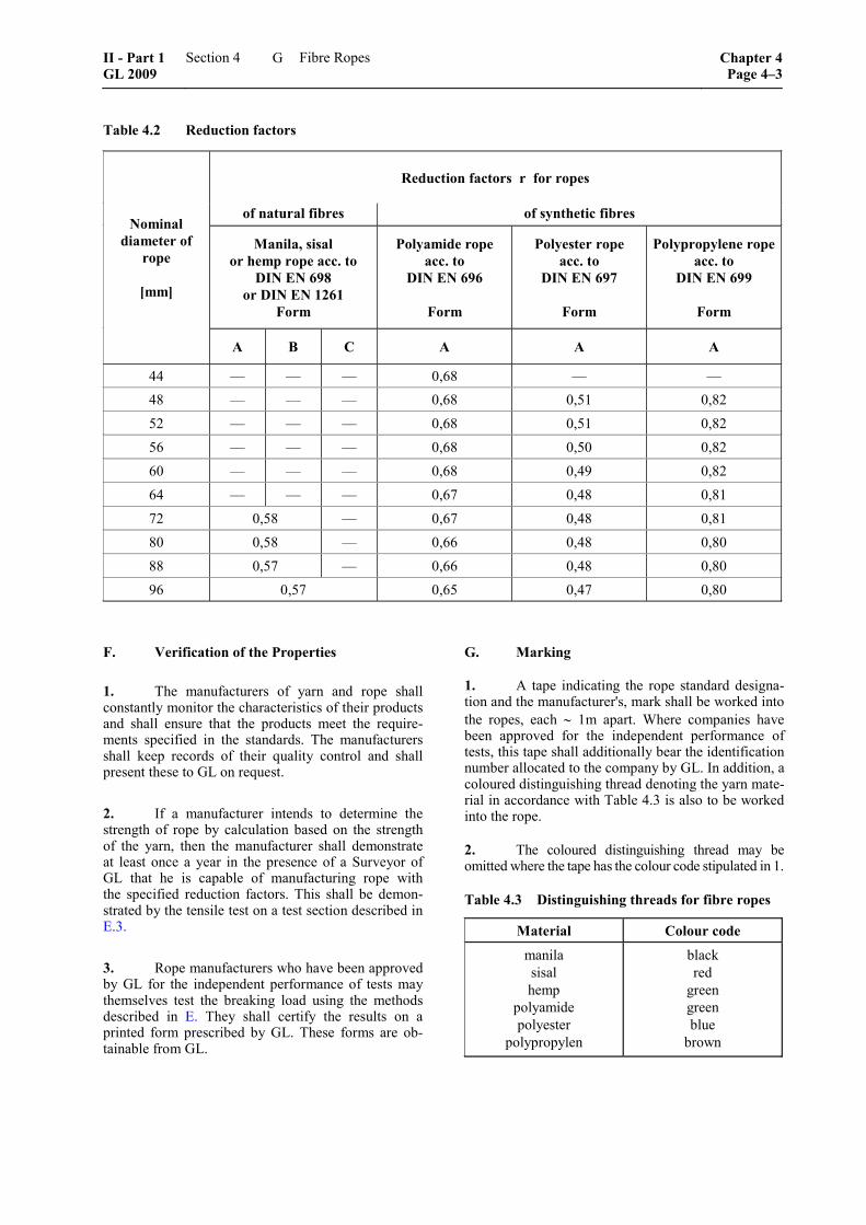
Table 4.2 Reduction factors
Reduction factors r for ropes
of natural fibres of synthetic fibres
Manila, sisal or hemp rope acc. to
DIN EN 698 or DIN EN 1261
Form
Polyamide rope acc. to
DIN EN 696
Form
Polyester rope acc. to
DIN EN 697
Form
Polypropylene ropeacc. to
DIN EN 699
Form
Nominal diameter of
rope
[mm]
A B C A A A
44 –– –– –– 0,68 –– –– 48 –– –– –– 0,68 0,51 0,82 52 –– –– –– 0,68 0,51 0,82 56 –– –– –– 0,68 0,50 0,82 60 –– –– –– 0,68 0,49 0,82 64 –– –– –– 0,67 0,48 0,81 72 0,58 –– 0,67 0,48 0,81 80 0,58 –– 0,66 0,48 0,80 88 0,57 –– 0,66 0,48 0,80 96 0,57 0,65 0,47 0,80
F. Verification of the Properties
1. The manufacturers of yarn and rope shall constantly monitor the characteristics of their products and shall ensure that the products meet the require-ments specified in the standards. The manufacturers shall keep records of their quality control and shall present these to GL on request.
2. If a manufacturer intends to determine the strength of rope by calculation based on the strength of the yarn, then the manufacturer shall demonstrate at least once a year in the presence of a Surveyor of GL that he is capable of manufacturing rope with the specified reduction factors. This shall be demon-strated by the tensile test on a test section described in E.3.
3. Rope manufacturers who have been approved by GL for the independent performance of tests may themselves test the breaking load using the methods described in E. They shall certify the results on a printed form prescribed by GL. These forms are ob-tainable from GL.
G. Marking
1. A tape indicating the rope standard designa-tion and the manufacturer's, mark shall be worked into the ropes, each ∼ 1m apart. Where companies have been approved for the independent performance of tests, this tape shall additionally bear the identification number allocated to the company by GL. In addition, a coloured distinguishing thread denoting the yarn mate-rial in accordance with Table 4.3 is also to be worked into the rope.
2. The coloured distinguishing thread may be omitted where the tape has the colour code stipulated in 1.
Table 4.3 Distinguishing threads for fibre ropes
Material Colour code
manila sisal hemp
polyamide polyester
polypropylen
black red
green green blue
brown
II - Part 1 GL 2009
Section 4 Fibre Ropes Chapter 4Page 4–3
G