Embed Size (px)
Citation preview

Run III limitations TCDQ, TCDS, TDE (related to beam impact)
A. Lechner, C. Bracco, M. Calviani, S. Gilardoni, C. Di Paolo, M. Fraser,M. Frankl, B. Goddard, F.X Nuiry, A. Perillo Marcone, T. Polzin, C. Wiesner
Most studies carried out within HL-LHC WP14
LHC Run III Configuration WG
June 29th, 2018
A. Lechner (LHC Run III Configuration WG) June 29th , 2018 1 / 24

Extraction protection devices and the dump in Run III
TCDS(absorber)
TCDQ(absorber)
TCTsIR1/5
(tert. coll.)
TCDQM(mask)
TCSP(sec. coll.)
TDE(dump)
MSD(septa)
Q4
Q5, DS
Main questions from Run III Conf WG concerning TCDS/TCDQ/TDE:
• Are there any limitations for TCDQ gap (for different bunch intensities, in particular below 1.7×10¹¹ ppb)?
• Is there a limitations for the bunch intensity due to the limited material robustness (TCDQ, TCDS, TDE)?
• Which upgrades (related to beam impact) are foreseen in LS2 and/or in Run III (for 2022 and/or 2023)?
Warning:
• This talk summarizes our present understanding (simulation results) but cannot answer all questions
A. Lechner (LHC Run III Configuration WG) June 29th , 2018 2 / 24
Contents
TCDQ
TCDS
TDE
A. Lechner (LHC Run III Configuration WG) June 29th , 2018 3 / 24

TCDQ upgrade history
• Was upgraded in LS1 (2→3 modules each 3 m long, Gr→CfC 1.4+1.8 g/cm3)
• Upgrade studies at that time (FLUKA+ANSYS) considered HL beam parameters→load was found to be well within material limits
• However, “new” MKD erratics observed in 2015: particle density on TCDQ can behigher than assumed for LS1 upgrade→ might limit the allowed half-gap
• As of now, no further absorber material upgrade planned within HL-LHC (WP14)
Particle distribution by TE-ABT (M. Fraser)
109
1010
1011
1012
1013
1014
1015
0 1 2 3 4
Par
ticl
e d
ensi
ty (
1/c
m)
x (cm)
TC
DQ
Sweep
Type 1 ErraticType 2 Erratic
A. Lechner (LHC Run III Configuration WG) June 29th , 2018 4 / 24

Assumed beam and optics parameters for TCDQ studies
• General remarks:→ Temperature fields in the most loaded blocks show little dependence on spot size (i.e. β and emittance) -
at least within a certain range
→ All studies were done with an emittance of 2.08µm·rad, but one can assume that conclusions are similar forBCMS beams (as long as the bunch intensity is the same)
• Optics (all studies carried out for optics version HLLHCV1.2 ):
Device Optics βx βy
√βxβy Remark
TCDQ HLLHCV1.2 497 m 167 m 288 m flat, end of squeeze, B1
Run 2 (2015) 484 m 161 m 279 m collision, B1
A. Lechner (LHC Run III Configuration WG) June 29th , 2018 5 / 24
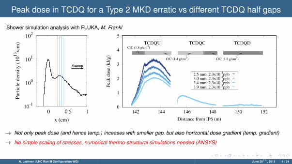
Peak dose in TCDQ for a Type 2 MKD erratic vs different TCDQ half gaps
Shower simulation analysis with FLUKA, M. Frankl
10-1
100
101
102
0 0.5 1
Sweep
Par
ticl
e d
ensi
ty (
10
13/c
m)
x (cm)
0
1
2
3
4
5
142 144 146 148 150 152P
eak d
ose
(kJ/
g)
Distance from IP6 (m)
2.5 mm, 2.3x10¹¹
ppb3.0 mm, 2.3x10
11ppb
3.4 mm, 2.3x10¹¹
ppb3.9 mm, 2.3x10
11ppb
CfC (1.8 g/cm3)
CfC (1.4 g/cm3) CfC (1.8 g/cm
3)
TCDQU TCDQC TCDQD
→ Not only peak dose (and hence temp.) inceases with smaller gap, but also horizontal dose gradient (temp. gradient)
→ No simple scaling of stresses, numerical thermo-structural simulations needed (ANSYS)
A. Lechner (LHC Run III Configuration WG) June 29th , 2018 6 / 24

Peak temperature and stresses in TCDQ for a Type 2 MKD erratic
EN-STI-TCD (C. Di Paolo et al.)
• Thermal and structural analysis for blocks with thehighest peak load (for both CfC grades and Graphiteblocks behind CfC)
• Studies completed so far: gap of 3.9 mm and a bunchpopulation 2.3×10¹¹ ppb
0
1
2
3
4
142 144 146 148 150 152
Pea
k d
ose
(kJ/
g)
Distance from IP6 (m)
Block #4Block #8
HL Std 25 nsec (εn=2.08µm rad, 2.3x10¹¹
ppb)CfC (1.8 g/cm3)
CfC (1.4 g/cm3) CfC (1.8 g/cm
3)
TCDQU TCDQC TCDQD
→ For this gap and bunch intensity, all materials OK, tensile and compressive principal stresses below the strength limits
A. Lechner (LHC Run III Configuration WG) June 29th , 2018 7 / 24

Preliminary remarks on TCDQ half gap vs bunch intensity
Shower simulation analysis with FLUKA, M. Frankl, temperatures rounded to 100◦C
1.4×10¹¹ 1.7×10¹¹ 2.0×10¹¹ 2.3×10¹¹
2.5 mm 2.0 kJ/g(1300◦C)
2.4 kJ/g(1500◦C)
2.8 kJ/g(1700◦C)
3.3 kJ/g(1900◦C)
3.0 mm 1.7 kJ/g(1100◦C)
2.0 kJ/g(1300◦C)
2.4 kJ/g(1500◦C)
2.7 kJ/g(1600◦C)
3.4 mm 1.5 kJ/g(1000◦C)
1.8 kJ/g(1200◦C)
2.1 kJ/g(1300◦C)
2.4 kJ/g(1500◦C)
3.9 mm 1.3 kJ/g(900◦C)
1.5 kJ/g(1000◦C)
1.8 kJ/g(1200◦C)
2.1 kJ/g(1300◦C)
• For a bunch intensity of 1.7×10¹¹, agap of 3 mm gives same peak temp.as 2.3×10¹¹ ppb+3.9 mm, yet thetemperature gradients are larger
• Very, very tentatively, one couldassume that for 1.7×10¹¹ the min.allowed gap could be around2.5-3.0 mm - TO BE CONFIRMED(but there is likely no/not much safetymargin accounting for simulationuncertainties→ acceptable??)
→ Remember: no simple scaling of stresses, numerical thermo-structural simulations needed (ANSYS)
→ More conclusive answer can hence only be given once thermo-structural results are available (end of September)
A. Lechner (LHC Run III Configuration WG) June 29th , 2018 8 / 24
Contents
TCDQ
TCDS
TDE
A. Lechner (LHC Run III Configuration WG) June 29th , 2018 9 / 24

TCDS
TCDSU
TCDSD
0.5m CfC
(1.7 g/cm3)
2m CfC
(1.4 g/cm3)
1.5m CfC
(1.7 g/cm3)
MSDA
Yoke
Coils
TCDS projectionon MSDA front face
Vacuum chambercirculating beam
Vacuum chamberextracted beam
Lower material density in region
of shower maximu
sweep
0.5m Gr
(1.8 g/cm3)
1m Gr
(1.8 g/cm3)0.5 Ti-alloy
(4.4 g/cm3)
• Existing TCDS:
◦ 2 modules, each with 3 m absorber length
◦ made of Graphite/2D CfC blocks of different density +Ti-alloy block at the downstream end
◦ each module has two jaws (one directly impacted incase of an asynchronous beam dump), all fixed apert.
• HL-LHC upgrade, WP14 (baseline):
◦ 2→ 3 modules in LS3 (upgrade studies yet to be started)
⇒ impact distribution (particle density) on TCDS does not depend significantly on type of erratic⇒ like for TCDQ, temperatures show limited sensitivity to emittance and beta-function
A. Lechner (LHC Run III Configuration WG) June 29th , 2018 10 / 24

Peak dose, temperature and stresses in TCDS for a Type 2 MKD erratic
M. Frankl, C. Di Paolo
• Thermal and structural analysis for blocks with thehighest peak load (for all materials)
• For a bunch intensity of 2.3×10¹¹ protons andemittance of 2.08µm·rad 0
1
2
3
4
0 1 2 3 4 5 6 7
Pea
k d
ose
(kJ/
g)
Distance from TCDS front (m)
HL Std 25 nsec (εn=2.08µm rad, 2.3x10¹¹
ppb)Graphite (1.8 g/cm
3)
CfC (1.75 g/cm3)
CfC (1.4 g/cm3)
CfC (1.75 g/cm3) Graphite (1.8 g/cm
3)
TCDSUTCDSD
Ti
→ CfC: OK, Graphite: max. tensile stress comparable to tensile strength (preliminary, results still to be verified!)
→ Ti: plastifies, but no risk of fracture (strain is 1%)
A. Lechner (LHC Run III Configuration WG) June 29th , 2018 11 / 24
Contents
TCDQ
TCDS
TDE
A. Lechner (LHC Run III Configuration WG) June 29th , 2018 12 / 24

TDE core
70 cm (1.77 g/cm3)
2mm sheets (1.1-1.2 g/cm3)
8 cm(1.72 g/cm3)
8 cm(1.72 g/cm3)
70 cm (1.77 g/cm3)
342 cm
TDE core:low and high-density graphitesegments
A. Lechner (LHC Run III Configuration WG) June 29th , 2018 13 / 24
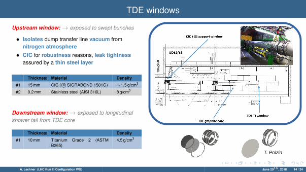
TDE windows
T. Polzin
Upstream window: → exposed to swept bunches
• Isolates dump transfer line vacuum fromnitrogen atmosphere
• CfC for robustness reasons, leak tightnessassured by a thin steel layer
Thickness Material Density
#1 15 mm CfC ( R©SIGRABOND 1501G) ∼1.5 g/cm3
#2 0.2 mm Stainless steel (AISI 316L) 8 g/cm3
Downstream window: → exposed to longitudinalshower tail from TDE core
Thickness Material Density
#1 10 mm Titanium Grade 2 (ASTMB265)
4.5 g/cm3
A. Lechner (LHC Run III Configuration WG) June 29th , 2018 14 / 24

Assumed beam and optics parameters for TDE studies
• General remarks:→ temp./stresses in upstream window depend on spot size (hence β, εn
x,y ) and bunch intensity (Ib)→ temp./stresses in core and downstream window not much sensitive to spot size, only to bunch intensity
• Assumed beam parameters:
Beam εnx,y Ib TDE component
HL Std 25 nsec 2.08µm·rad 2.3×10¹¹ downstream window, dump core
LIU BCMS 1.37µm·rad 2.0×10¹¹ upstream window
→ this is a cautious approach, i.e. no emittance growth and no intensity loss in ramp→ studies for 1.7µm·rad 2.3×10¹¹ ongoing for upstream window→ expect somewhat higher stresses although
brightness is the same
• Optics (all studies carried out for optics version HLLHCV1.2 ):
Device Optics βx βy
√βxβy Remark
TDE HLLHCV1.2 5052 m 3714 m 4331 m round, end of squeeze, B2
Run 2 (2015) 5076 m 3713 m 4341 m collision, B2
→ for upstream window, we also studied effect of increased β (only temperatures, no stress calculations)
A. Lechner (LHC Run III Configuration WG) June 29th , 2018 15 / 24
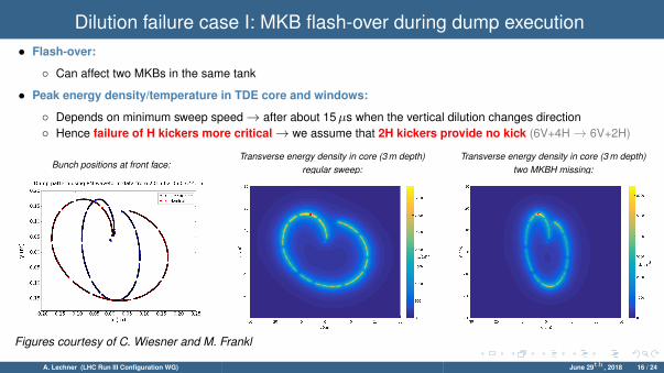
Dilution failure case I: MKB flash-over during dump execution• Flash-over:
◦ Can affect two MKBs in the same tank
• Peak energy density/temperature in TDE core and windows:
◦ Depends on minimum sweep speed→ after about 15µs when the vertical dilution changes direction◦ Hence failure of H kickers more critical→ we assume that 2H kickers provide no kick (6V+4H→ 6V+2H)
Bunch positions at front face:Transverse energy density in core (3 m depth)
regular sweep:Transverse energy density in core (3 m depth)
two MKBH missing:
Figures courtesy of C. Wiesner and M. Frankl
A. Lechner (LHC Run III Configuration WG) June 29th , 2018 16 / 24
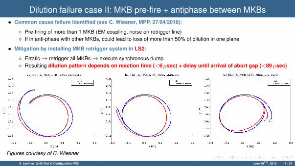
Dilution failure case II: MKB pre-fire + antiphase between MKBs• Common cause failure identified (see C. Wiesner, MPP, 27/04/2018):
◦ Pre-firing of more than 1 MKB (EM coupling, noise on retrigger line)◦ If in anti-phase with other MKBs, could lead to loss of more than 50% of dilution in one plane
• Mitigation by installing MKB retrigger system in LS2:
◦ Erratic→ retrigger all MKBs→ execute synchronous dump◦ Resulting dilution pattern depends on reaction time (<6µsec) + delay until arrival of abort gap (<89µsec)
Figures courtesy of C. Wiesner
A. Lechner (LHC Run III Configuration WG) June 29th , 2018 17 / 24

Temperatures in the TDE core (regular sweep and failure case I - flash-over)M. Frankl
0 50 100 150 200 250 300 350 400 450 500
Depth [cm]
0
500
1000
1500
2000
2500
3000
Tem
pera
ture
[° C
]
TDE Core Temperature, HL-STD ( = 2.08 mrad, 2748b, 2.3e11 ppb)
1.77 g/cm3
1.2 g/cm3 1.77 g/cm3
HL-STD, MKB 6V/2HHL-STD, nominal sweep
• Peak temperatures (◦C) in the TDE core for2.3×1011 bunch intensity, 2.08µm emittance
• The temperatures in the dump core are very high in all cases
• In the case of 2H kicker failure scenario (flash-over) peak close to sublimation temperature
• Analysis of stresses→ better material characterization needed (ongoing in EN/STI/TCD)
A. Lechner (LHC Run III Configuration WG) June 29th , 2018 18 / 24
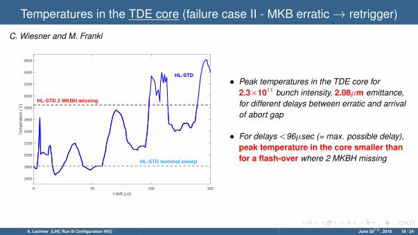
Temperatures in the TDE core (failure case II - MKB erratic→ retrigger)
C. Wiesner and M. Frankl
0 50 100 150
t-shift ( s)
1600
1800
2000
2200
2400
2600
2800
3000
3200
3400
3600
Tem
pera
ture
(° C
)
HL-STD 2 MKBH missing
HL-STD nominal sweep
HL-STD• Peak temperatures in the TDE core for
2.3×10¹¹ bunch intensity, 2.08µm emittance,for different delays between erratic and arrivalof abort gap
• For delays <96µsec (= max. possible delay),peak temperature in the core smaller thanfor a flash-over where 2 MKBH missing
A. Lechner (LHC Run III Configuration WG) June 29th , 2018 19 / 24

Temp. & stresses in upstream window (regular sweep + failure cases I/II)C. Wiesner, M. Frankl, T. Polzin
0 50 100 150
t-shift ( s)
40
50
60
70
80
90
100
110
120
130
140
Tem
pera
ture
(° C
)
HL-BCMS nominal sweep
HL-BCMS
HL-BCMS 2 MKBH missing
Case Sy
Regular sweep 1.9
Failure case I (2H flash-over) 0.9
Failure case II (retrigger) ongoing
All results are for 2.0×10¹¹ bunch intensity,1.37µm emittance (BCMS beams)
• Figure: peak temperatures
→ blue dashed line: regular sweep→ red dashed line: 2 MKBH flash-over→ dark blue line: retrigger (diff. delays)
Note: eventually not the temperature butthe thermal stresses matter!
• Table: safety margin Sy against yielding(permanent deformation):
Sy = Ry/σeq (1)
where Ry =yield strength of the material,σeq=equ. van Mises stresses→ Sy should be larger than 2 (minimumsafety margin), not the case for HL beams
A. Lechner (LHC Run III Configuration WG) June 29th , 2018 20 / 24
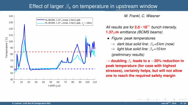
Effect of larger βx on temperature in upstream window
M. Frankl, C. Wiesner
0 10 20 30 40 50 60 70 80 90 100 110
t-shift ( s)
40
50
60
70
80
90
100
110
120
130
140
Tem
pera
ture
(° C
)
HL-BCMS, 1.37 mrad, 2.0e11 ppbHL-BCMS, 1.37 mrad, 2.0e11 ppb,
x = 10km
All results are for 2.0×10¹¹ bunch intensity,1.37µm emittance (BCMS beams)
• Figure: peak temperatures
→ dark blue solid line: βx =5 km (now)→ light blue solid line: βx =10 km
(preliminary results)
→ doubling βx leads to a ∼20% reduction inpeak temperature (for case with higheststresses), certainly helps, but will not allowone to reach the required safety margin
A. Lechner (LHC Run III Configuration WG) June 29th , 2018 21 / 24
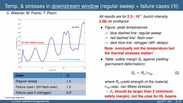
Temp. & stresses in downstream window (regular sweep + failure cases I/II)C. Wiesner, M. Frankl, T. Polzin
0 50 100 150
t-shift ( s)
140
160
180
200
220
240
260
280
300
320
340
360
Tem
pera
ture
(° C
)
HL-STD
HL-STD nominal sweep
HL-STD 2 MKBH missing
Case Sy
Regular sweep 1.4
Failure case I (2H flash-over) 1.3
Failure case II (retrigger) 0.6*∗ worst case (delay time)
All results are for 2.3×10¹¹ bunch intensity,2.08µm emittance
• Figure: peak temperatures
→ blue dashed line: regular sweep→ red dashed line: flash-over→ dark blue line: retrigger (diff. delays)
Note: eventually not the temperature butthe thermal stresses matter!
• Table: safety margin Sy against yielding(permanent deformation):
Sy = Ry/σeq (2)
where Ry =yield strength of the material,σeq=equ. van Mises stresses→ Sy should be larger than 2 (minimumsafety margin), not the case for HL beams
A. Lechner (LHC Run III Configuration WG) June 29th , 2018 22 / 24
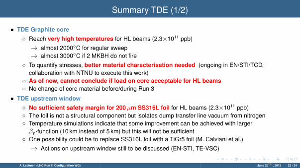
Summary TDE (1/2)
• TDE Graphite core◦ Reach very high temperatures for HL beams (2.3×10¹¹ ppb)
→ almost 2000◦C for regular sweep→ almost 3000◦C if 2 MKBH do not fire
◦ To quantify stresses, better material characterisation needed (ongoing in EN/STI/TCD,collaboration with NTNU to execute this work)
◦ As of now, cannot conclude if load on core acceptable for HL beams◦ No change of core material before/during Run 3
• TDE upstream window◦ No sufficient safety margin for 200µm SS316L foil for HL beams (2.3×10¹¹ ppb)◦ The foil is not a structural component but isolates dump transfer line vacuum from nitrogen◦ Temperature simulations indicate that some improvement can be achieved with largerβy -function (10 km instead of 5 km) but this will not be sufficient
◦ One possibility could be to replace SS316L foil with a TiGr5 foil (M. Calviani et al.)
→ Actions on upstream window still to be discussed (EN-STI, TE-VSC)
A. Lechner (LHC Run III Configuration WG) June 29th , 2018 23 / 24
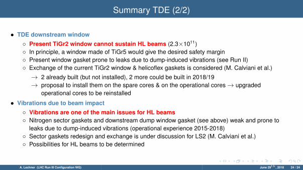
Summary TDE (2/2)
• TDE downstream window◦ Present TiGr2 window cannot sustain HL beams (2.3×10¹¹)◦ In principle, a window made of TiGr5 would give the desired safety margin◦ Present window gasket prone to leaks due to dump-induced vibrations (see Run II)◦ Exchange of the current TiGr2 window & helicoflex gaskets is considered (M. Calviani et al.)
→ 2 already built (but not installed), 2 more could be built in 2018/19→ proposal to install them on the spare cores & on the operational cores→ upgraded
operational cores to be reinstalled
• Vibrations due to beam impact◦ Vibrations are one of the main issues for HL beams◦ Nitrogen sector gaskets and downstream dump window gasket (see above) weak and prone to
leaks due to dump-induced vibrations (operational experience 2015-2018)◦ Sector gaskets redesign and exchange is under discussion for LS2 (M. Calviani et al.)◦ Possibilities for HL beams to be determined
A. Lechner (LHC Run III Configuration WG) June 29th , 2018 24 / 24