Embed Size (px)
Citation preview

RUPLAN EVU-Module 2020
Update Information
2/7/2020
AUCOTEC AG Oldenburger Allee 24
D-30659 Hannover
Phone: +49 (0)511 61 03-0
Fax: +49 (0)511 61 40 74
www.aucotec.com
AUCOTEC, INC. 17177 North Laurel Park Drive,
Suite 437
Livonia, MI 48152
Phone: +1 630 485 5600
Fax: +1 248 655 7800

Copyright: All rights, especially the right of reproduction and distribution as well as
translation, are reserved. No part of this book may be reproduced, stored in retrieval
system, or transmitted in any form or by any means, electronic, mechanical, photocopy-
ing, microfilming, recording, or otherwise, without prior permission from AUCOTEC AG.
Exclusion of liability: Texts and software have been prepared with the greatest of care.
The publishers as well as the authors cannot assume any legal or other liability of any
nature for potential faulty statements and their consequences, which shall apply also for
the software potentially included.
Trademarks RUPLAN® is a registered trademark of the AUCOTEC AG, Germany. Mi-
crosoft Windows® is a registered trademark of Microsoft Corporation, USA.

Content
i
Content
1 Important Note ...................................................................... 1
2 New Features in the EVU Module ............................................ 2
3 RUPLAN environment ............................................................. 3
3.1 Installation file ..................................................................................... 3
3.2 Standard text files ................................................................................ 4
3.3 RUPLAN Data ........................................................................................ 4
3.3.1 Sample Project .................................................................................... 4
4 Catalog and Catalog User Menu .............................................. 5
4.1 NEW: Shrink project libraries ................................................................ 5
4.2 Update EVU-module-db ......................................................................... 5
4.3 Catalog user menu: start eval. in select. pros ....................................... 5
5 Object editing ........................................................................ 6
5.1 Evaluations in the object library ........................................................... 6
6 New workflow with wiring material ....................................... 7
6.1 Previous workflow ................................................................................ 7
6.2 New workflow ....................................................................................... 7
6.3 New wiring material selection .............................................................. 8
6.4 Optional addresses: catalog and table ................................................ 10
6.4.1 Wiring material catalog ........................................................................10
6.4.2 Optional wiring material table ...............................................................11
6.5 Equalization of wiring material spellings ............................................ 11
6.6 Conversion of a project ....................................................................... 12
6.6.1 Preparative actions .............................................................................12
6.6.2 Preparative consistency check ..............................................................13
6.6.3 Correction aid to the consistency check .................................................14
6.6.4 Conversion of the project .....................................................................16
6.6.5 Adaption of the defaults for network texts ..............................................20
6.7 Merging old plans in a converted project ............................................ 20
6.7.1 Preliminary remarks ............................................................................20
6.7.2 Conversion of imported plans ...............................................................21
6.7.3 Creating an auxiliary wiring material table .............................................22

Contents
7 Sheet editing ........................................................................ 24
7.1 New fittings for the terminal diagrams editing ................................... 24
7.2 New potential interruption symbol ..................................................... 26
7.3 Graphics ............................................................................................. 26
7.4 Context menus .................................................................................... 27
7.5 Toolbars and icons .............................................................................. 28
8 Evaluations .......................................................................... 30
8.1 General Information ........................................................................... 30
8.2 Menu "EVU-module compact" ............................................................. 30
8.2.1 Modify this menu (compact) .................................................................30
8.3 Menu "General diagram processing" ................................................... 30
8.3.1 Main menu .........................................................................................30
8.3.2 Submenu "Edit symbols" ......................................................................31
8.4 Menu "Circuit diagram commands" ..................................................... 32
8.4.1 NEW: Submenu "Wiring material" .........................................................32
8.5 Menu "Online control" ........................................................................ 33
8.5.1 Submenu "Entries preceding obj. ref." ...................................................33
8.5.2 Submenu "Checks preceding obj. ref." ...................................................34
8.6 Menu "Device documents" .................................................................. 34
8.6.1 Sub menu "Preparation/after-treatment" ...............................................34
8.7 Menu "Terminal diagram" ................................................................... 34
8.7.1 Main menu .........................................................................................34
8.7.1.1 Create TDR-definition sheets ............................................................34
8.7.1.2 Create terminal diagram ..................................................................35
8.7.1.3 Data transfer TDR -> CDR ...............................................................35
8.7.1.4 Data transf. wir. mat. TDR -> CDR ....................................................36
8.7.2 Submenu "Special cases of term. dgr." ..................................................36
8.8 Menu "Cable documents" .................................................................... 37
8.8.1 Main menu .........................................................................................37
8.8.1.1 NEW: Cable destination editor ..........................................................37
8.9 Menu "Wiring diagrams" ..................................................................... 37
8.9.1 Settings for CCD/WD ...........................................................................37
8.9.2 Cross connection diagram / Wiring list ...................................................37
8.9.3 Cross connection diagram (previous form) .............................................37
8.9.4 Device wiring list (Device connection list) ..............................................38
8.9.5 Plug connection diagram ......................................................................38
8.9.6 Check: faulty networks ........................................................................38

Contents
8.10 Menu "Administration commands" ..................................................... 39
8.10.1 Project administration .........................................................................39
8.10.1.1 Project options: "EVU module" ..........................................................39
8.10.2 Submenu "Administrat. addresses/files" ................................................39
8.11 Menu "Modules" ................................................................................. 40
8.11.1 Cad-Cabel interface .............................................................................40
9 QA tools ............................................................................... 41
9.1 General data check ............................................................................. 41
9.1.1 Incomplete data .................................................................................41
9.1.2 Unknown symbols ...............................................................................41
9.2 Objects and devices ............................................................................ 42
9.2.1 Device check ......................................................................................42
9.3 Symbols and designation .................................................................... 42
9.3.1 Item captioning ..................................................................................42
9.3.2 Captioning of termin./plugs ..................................................................43
9.4 Connections and potentials ................................................................. 43
9.4.1 Faulty pot./cross ref. symb. .................................................................43
9.5 Circuit dgr. accomp. docu. .............................................................. 44
9.5.1 Term.: circuit diagram terminal diagram ............................................44
9.5.2 Item definition resource schedules ....................................................45
9.5.3 All sheets list of documents ..............................................................45
9.6 QS-tools acc. to previous versions ...................................................... 45
9.6.1 QS-tools acc. to EVU-module 2019........................................................45
10 Reference data ..................................................................... 46
10.1 Symbols .............................................................................................. 46
10.1.1 New reference symbols ........................................................................46
10.1.2 Changes on reference symbols .............................................................46
10.2 Sheets ................................................................................................ 48
10.2.1 New sheets ........................................................................................48
10.2.2 Changes on form sheets ......................................................................48

Important Note
- 1 -
1 Important Note
With EVU-module 2020 the workflow for wiring material was changed: The reference via
position numbers in circuit diagrams to a wiring material table was abandoned: see chap-
ter 6, "New workflow with wiring material".
Plans stemming from previous versions have to be adapted to the new workflow before
further processing: see chapter 6.6, "Conversion of a project".
Plans that were adapted or created anew in EVU-module 2020 cannot anymore
be processed in previous versions! Plans in EVU-module 2020 are not downward
compatible!

New Features in the EVU Module
- 2 -
2 New Features in the EVU Module
The most important news in EVU module 2020 are:
Abandonment of the references to the wiring material table
With this version 2020, the workflow for wiring material is changed funda-
mentally: In the circuit diagrams and the definition symbols, position num-
bers for wiring material are no longer used, instead the material data itself
is entered in these plans and symbols.
Evaluations to convert a project to this new workflow are available.
See chapter no.6, New workflow with wiring material
New fitting symbols for reducing jumpers and separating plates
For constellations where a jumper crossing a partition element is possible,
new symbols were made available. If those symbols are used, the QA ter-
minal diagram check does not report such a constellation as an error.
See chapter no. 7.1 and 9.5.1
Data transfer TDR ➔ CDR with navigation information
With the data transfer from TDR to CDR, now terminals in the circuit dia-
gram are supplied with navigation information of the corresponding termi-
nal diagram line, thus enabling specific navigation from the circuit diagram
to the terminal diagram without online references for terminals.
See chapter 8.7.1.3
QA tools: Check of terminal diagram symbol names
Two QA checks were upgraded to the effect that they check symbol names
for the terminal diagram regarding their conformity with the name rules of
the Guidelines, chapter 14.5:
- Captioning of terminals/plugs: see chapter no. 9.3.2
- Terminals CDR TDR: see chapter no. 9.5.1
QA tools: Check for unknown symbols expanded
The QA check "Unknown symbols" now also checks symbol names in text
nodes that are read by evaluations.
See chapter no. 9.1.2
Shrink project libraries
For a project, the shrinking of its libraries can be triggered.
See chapter no. 4.1
New potential interruption symbol with complete ib + bb
With this version, the potential interruption symbol GJ520 with complete
identifying and describing bloc is available.
See chapter no. 7.2 and 10.1.1

RUPLAN environment
- 3 -
3 RUPLAN environment
3.1 Installation file
DEFAULTS FOR NETWORK TEXTS
With EVU-module 2020 the reference to the wiring material table via position numbers is
abandoned; see the detailed description in chapter 6.
With the new workflow, the connection lines in the graphic editing do not any longer car-
ry position numbers. Consequently, the 3 text nodes provided at connection lines for the
entry of a position number were removed from the default definition in the installation
file. The text nodes 'N&POS', 'POS' and 'VPOS' no longer appear in these default defini-
tions:
In the EVU-module installation file delivered with version 2020, the coordinates of the
remaining wiring material texts were adapted; but that is of little importance because
this information is usually invisible.
Projects transferred from previous version to EVU-module 2020 still con-
tain the old defaults for network texts.
If the text nodes for position numbers have no entries, then in principle
this is no problem.
Though, to avoid faulty entries, it is advisable to adapt the user defaults
in the project to the state of the installation file of EVU 2020, via reset to
these defaults.
In graphic editing, the Icon leads to the "Defaults":

RUPLAN environment
- 4 -
3.2 Standard text files
Files for standard text form libraries
• In the standard text files ENGnrm_EVU_FORM.txt the code _DOK099 was supple-
mented.
• In the texts to _KAB047, _KAB048, _QSW009, _QSW010 and _QSW011 the quota-
tion marks were replaced by ">" / "<" (necessary for a correct migration to Engineer-
ing Base; see also chapter 10.1.2).
• For the pre-set in wire symbols of 'LPOS' with "Wire" resp. "Draht" (see chapter
10.1.2) the code _VDR163 was supplemented.
3.3 RUPLAN Data
3.3.1 Sample Project
EVU2020E
General change
The sample project was converted to the new workflow with wiring material (see chapter
6, "New workflow with wiring material").
With the conversion, a TEC wiring material catalog and an optional wiring material table
were created (see chapter 6.6.4, "Conversion of the project").

Catalog and Catalog User Menu
- 5 -
4 Catalog and Catalog User Menu
4.1 NEW: Shrink project libraries
Since RUPLAN 4.82 the feature "Shrink" is available in the menu "Library": Via this fea-
ture, RUPLAN libraries with little content can be reduced to the size needed for the con-
tent. Each library to be shrunk must be marked.
With "Shrink project libraries" in the menu "Project" this feature now can be started on a
project: By this, the libraries belonging to the project will be shrunk without the need to
mark these libraries themselves.
4.2 Update EVU-module-db
Change
The update of the EVU-module-libraries was upgraded to the version 2020.
4.3 Catalog user menu: start eval. in select. pros
Change
When creating the project list for this feature, up to now all marked projects without ex-
ception were entered in this list
From now on the following AUCOTEC reference projects are automatically excluded from
the list:
X00* STA* BSB* BOB* FLUID* PCO* *BSP*
EVUQS* SSL* SPS* ETI KBM* EVU* KKS*
Object editing
- 6 -
5 Object editing
5.1 Evaluations in the object library
TEC: copy TEC into 1st db
New feature:
To the list of TEC-objects to be copied the catalog object for wiring material was added:
TEC / W00000W0.
Via project options (see chapter 8.10.1.1) this new catalog object can be excluded from
the copy list.

New workflow with wiring material
- 7 -
6 New workflow with wiring material
6.1 Previous workflow
In RUPLAN EVU, wiring material is defined by 3 values: material, cross section and color.
In previous EVU-module-versions a wiring material table was used to assign position
numbers to the different wiring material, e.g.:
In the plans only the position number was entered, and only if required (e.g. wiring ma-
terial information in the terminal diagram), it was translated via the wiring material table
into the actual material information.
This workflow repeatedly led to problems with data exchange, if sender and receiver of
data worked with different wiring material tables, or if the wiring material table was not
delivered.
6.2 New workflow
Therefore, a new workflow it introduced with EVU-module 2020:
For wiring material there no longer references are made via position
numbers!
In the plans, the wiring material itself, comprising material, cross section and color, are
entered. Depending on the material, not all three values must be entered.
Hierarchy for wiring material information
The hierarchy henceforth valid for position numbers was kept and supplemented by an
additional hierarchy level:
Hierarchy
level
Filing of the in-
formation Kind of information Text nodes
1 connection connection texts VMAT, VQUER, VFARBE
2 connection sub-network texts MAT, QUER, FARBE
3 connection network texts N&MAT, N&QUER,
N&FARBE
4 sheet title block title block symbol texts RMAT, RQUER, RFARBE
5 project options Diagram Processing / Cir-
cuit diagram processing
C&STDMAT,
C&STDQUE, C&STDFAR

New workflow with wiring material
- 8 -
Different handling of standard wiring material in previous and new versions
The fifth hierarchy level results in a different effect for connections in circuit diagrams,
whose material is not laid down, neither at the connection itself nor at the title block of
the sheet.
In previous versions, these unlabeled connections got their material information only in
the related wiring document, via header entries, especially in the terminal diagram head-
er.
Thereby, inconsistent wiring documents could be created: If there existed a connection
between a terminal of terminal strip A and a terminal of terminal strip B, and if the
standard material for terminal strip A had a cross section of 1,5mm², whereas the stand-
ard material of terminal strip B had a cross section of 2,5mm², then between the two
terminal strips, two wires "met" with different cross sections!
Such a discrepancy is not possible anymore with the new workflow.
In plans stemming from a previous version, newly created terminal dia-
grams should be checked concerning the standard material; there may
be discrepancies because of the changes described above.
These discrepancies can be avoided or at least minimized by performing
Data trans. wir. mat. TDR – CDR (see chapter 6.6.1).
6.3 New wiring material selection
During project work, at several spots wiring material is entered at a connection or a
symbol. In the past, at these spots the content of the wiring material table was offered in
a selection mask.
With the new workflow the system distinguishes:
If a wiring material catalog as described below exists in the project, then the content of
this catalog is offered in a selection mask.
Example:
As before, a selection can be performed by double klick or via the right mouse key.

New workflow with wiring material
- 9 -
If a material shall be entered that is not contained in the selection list, one can mark
Manual entry in the header; then, after confirming the mask, the following window is
displayed:
For each of the 3 material attributes, a separate entry field is offered. In each field, a
pull-down menu can be opened. If nothing suitable is found in the pull-down menu, the
desired entry can be entered manually.
If no wiring material catalog is found in the project, the manual entry
mask shown above is opened directly.

New workflow with wiring material
- 10 -
6.4 Optional addresses: catalog and table
6.4.1 Wiring material catalog
For quick and uniform selection, wiring material can be entered into a wiring material
catalog.
The catalog is kept as a TEC object: TEC W00000W0:
This table consists of the technical data symbols TJ710 (header) and TJ711 (simple line):
The use of a wiring material catalog is optional!

New workflow with wiring material
- 11 -
6.4.2 Optional wiring material table
It is possible and permissible to keep an optional wiring material table as a sheet. It
looks the same as the previous wiring material table but is placed in a different RUPLAN-
function: WIRING-MATERIAL-2020.
This optional table is used by the evaluations Terminal diagram and CCD *previous
form*:
• The terminal diagram with cable matrix needs position numbers to refer in the
terminal lines to material information in the header symbol.
• Without optional wiring material table, the position numbers are created anew
with the creation of the terminal diagram. Thus, identical wiring material is not
necessarily represented by the same position number.
• If there exists an optional wiring material table, its position numbers are as-
signed to the material data found in the circuit diagram and is entered in the
terminal diagram. In this case, a position number always represents the same
material.
• The cross-connection diagram (CCD) *previous form* can display a position
number to each material entry.
• If no optional wiring material table exists in the project, the corresponding field
in the form sheet stays empty.
• If an optional wiring material table exists, then the evaluation gets the corre-
sponding position number for each material entry from this optional table.
6.5 Equalization of wiring material spellings
Occasionally, especially via data transfer, differing spelling sneaks in for identical materi-
al information, e.g. for the cross section ("1mm²" "1,0MM2") or the color ("bl"
"BU").
The evaluation Equalize wiring mat. spellings in the menu Circuit diagram com-
mands, submenu Wiring material, supports the user with the equalization.
This evaluation lists all wiring material information found in the plans and, if existing, in
the TEC wiring material catalog, and groups material likely to be the same.
In the entry mask the data can be modified as required. The modifications are written
back to all places concerned.

New workflow with wiring material
- 12 -
Entry mask to equalize wiring material spelling:
If a wiring material catalog (TEC) exists, the spellings derived from this catalog are
marked with an X in column S4 (Cat).
6.6 Conversion of a project
6.6.1 Preparative actions
If, to be on the safe side, you want to create the wiring docu-
ments anew, you must do this in the previous EVU-module ver-
sion!
In EVU-module 2020, the evaluations to create wiring documents cannot
any more interpret position numbers in the plans! Without previous con-
version of the project, the wiring document evaluations would produce
faulty results!
Before starting the conversion evaluation Switch: pos. to material you should perform
the following steps:
If you can assume that the wiring information in the terminal diagrams is correct,
then perform the evaluation Data transf. wir. mat. TDR->CDR (in the menu Ter-
minal diagram).
Check the sheets in the RUPLAN function WIRING-MATERIAL. Only the sheet resp.
sheets with the valid wiring material data should lie in this function, when the con-
version evaluation is started.
If need be, move the sheets that are not relevant to another function, e.g.
RES_WIRING-MATERIAL.

New workflow with wiring material
- 13 -
The conversion can only be performed, if an "old" wiring mate-
rial table is available. If this table is missing, an auxiliary table
can be derived from the entries in the existing plans; see below,
chapter 6.7.3, "Creating an auxiliary wiring material table".
This auxiliary table possibly is incomplete and/or ambiguous –
depending on the quality of the plans the information is taken
from.
Check the consistency of the wiring material entries with the corresponding evalua-
tion, which is described in the following section: chapter 6.6.2, "Preparative consis-
tency check".
Correct inconsistent entries in your plans.
6.6.2 Preparative consistency check
Before starting the conversion, the consistency of the existing wiring material entries
with the wiring material table should be checked. For this purpose, a preparative check is
available, which is described in this chapter.
The evaluation mentioned here cannot check if the material entries the
circuit diagram is consistent with the material entries in the wiring dia-
grams!
Here only visual control of the plans can help, or – even better – the
new creation of the wiring diagrams. Here it is absolutely necessary to
observe the following:
NOTE: The recommended new creation of wiring diagrams must
be performed in the old EVU-module version, because the wiring
diagram evaluations in EVU-module 2020 no longer evaluate po-
sition numbers in the circuit diagram, and therefore produce
faulty plans if started before the conversion!
The Wiring mat consistency check can be started in the menu Circuit diagram
commands \ Wiring material \ Conversion to new workflow:

New workflow with wiring material
- 14 -
This check evaluation examines
• if entries of position numbers with material information (e.g. title block entries or en-
tries in some of the derived documents) fit to the entries of the wiring material table,
• if position numbers without material information (e.g. entries at connection lines) are
contained in the wiring material table, and
• if in the wiring material table one position number is associated with differing material
information.
All the plans in the project are checked, no matter which plans were
marked for the start of the evaluation.
If errors are detected, an error list is displayed, with the option to navigate to the error
spots:
If possible, all errors reported should be fixed before starting the con-
version!
6.6.3 Correction aid to the consistency check
If the consistency check described in the previous chapter was performed, an evaluation
to support corrections is available: Lmat correction aid, in the menu directly below the
consistency check. This evaluation is designed specially to change big numbers of similar
errors.
The evaluation reads the current error file of the consistency check and offers the error
lines for correction. In succession, in one window, the lines for one position number are
offered for change:

New workflow with wiring material
- 15 -
If for the position number currently displayed in this window, an entry exists in the old
wiring material table, this entry is displayed in the header. Otherwise, the text "no entry
in the wiring mat table" is entered.
For the lines, a multi-select is possible.
Via the context menu, an action can be chosen. This action will then be performed for all
marked lines.
• Assign material: leads to a selection dialog resp. a supported entry mask for wiring
material; the selected material will be written to all marked lines
• Delete position number: deletes the entry of the position number in all marked
lines
• Delete material data: deletes the entries of material, cross section and color in all
marked lines
• Delete position number and material data: deletes position number, material,
cross section and color in all marked lines
• Enter changes into the sheets: writes the changes in this window into the marked
sheets
In succession, the lines for the next position number are offered for change.
At the end of the evaluation, the error list of the consistency check is deleted, because it
doesn't fit any longer to the current state of the plans.

New workflow with wiring material
- 16 -
Note: It is advisable to start the evaluation Data transf. wir. mat. TDR-
>CDR (in the menu Terminal diagram) again after performing the correction
aid evaluation.
Note: Not with RIS-data or copied sheet addresses!
This is especially important if entries in terminal diagram definition symbols
and terminal diagram header symbols have been changed:
6.6.4 Conversion of the project
To convert a project to the new workflow with the wiring material, the evaluation
Switch: pos. to material is started in the menu Circuit diagram commands \ Wiring
material \ Conversion to new workflow:

New workflow with wiring material
- 17 -
This conversion evaluation replaces the position numbers in the plans by the material
assigned to a position number in the wiring material table:
Connection line before: Connection line after:
If the evaluation comes across discrepancies between position number and material in-
formation, the position number wins, i.e. differing material information is overwritten.
This can only be avoided by starting the consistency check first (see chapter 6.6.2) and
correcting the reported errors.
All the plans in the project are converted, no matter which plans were
marked for the start of the evaluation.
Action sequence
At the start, the conversion evaluation checks a temporary marker that is set during the
run of the consistency check. If the marker is not set, the following hint is displayed:
Depending on the state of the project, at this point you can abort the evaluation to per-
form the preparatory steps, or you can go on with the conversion by clicking Continue.

New workflow with wiring material
- 18 -
Before converting, the evaluation inquires if the old wiring material table should be trans-
ferred into a wiring material catalog and / or an optional wiring material table:
Wiring material catalog
The content of the old wiring material table is written into a TEC object W00000W0,
leaving out the position number. This TEC object serves as source for the selection
of wiring material in the plans, as did the old wiring material table.
The layout of the object resembles that of the old wiring material table.
Optional wiring material table
The old wiring material table is moved to the function WIRING-MATERIAL-2020. It
serves as a reference for wiring diagrams that contain position numbers; these are
terminal diagrams with cable matrix and cross connection diagrams in the previous
form.
If no optional wiring material table is found, the position numbers are entered in
these sheets by the evaluation via simple counting.
Continuing, the evaluation compares the old standard material in the header of the wir-
ing material table with the standard material that is pinned down in the project options
since EVU module 2020. If these standard material entries differ, the user must decide
how to proceed:

New workflow with wiring material
- 19 -
Usually, the previous standard material should be kept, this decision is
met by the default 1: Wmat-table standard.
If the two terms only differ in spelling, as in the screenshot ("1,5mm²"
= "1,5mm2"), then the option 2: Project standard may be chosen: By
this option, the standard material entries in the plans are adapted to the
standard material of the project options.
If after the conversion the plans shall be transferred to another project,
and if the material in the wiring material table header symbol differs
from the standard material in the target project, then the option
3: Entry into sheet frames should be chosen.
With this option, the material of the wiring material table header symbol
will be written into the title blocks of the circuit diagrams, into the text
nodes 'RMAT', 'RQUER' and 'RFARBE'.
Title block symbols that already carry an inscription in these text nodes,
are not altered.
After answering both inquiries, the position numbers in the plans are converted to mate-
rial information.
Depending on the answers to the selection of replacement addresses (see above), the
requested addresses are generated.
If during the conversion the evaluation comes across an error, an error list will be dis-
played at the end:
If after the conversion a situation arises, that equal wiring material en-
tries are treated as different just because of a differing spelling, then an
equalizing of these spellings may be performed for the project; see
chapter 8.4.1, "NEW: Submenu "Wiring material"".

New workflow with wiring material
- 20 -
6.6.5 Adaption of the defaults for network texts
With the new workflow, the text nodes for position numbers should no longer be availa-
ble at the connections.
If RUPLAN EVU 2020 is started with the settings of the installation file delivered with ver-
sion 2020, this state can be settled by the evaluation Switch: network text defaults in
the menu Circuit diagram commands \ Wiring material \ Conversion to new
workflow.
Connection edit mask
before evaluation: after evaluation:
Leftover position numbers that happen to still stand at connections are
not deleted by this setting adaption! They remain at the connection as
additional texts and are only moved to the end of the edit mask.
If the evaluation does not produce the described result, you should
check the settings of your installation file see chapter 3.1, "Installation
file").
6.7 Merging old plans in a converted project
6.7.1 Preliminary remarks
This chapter describes the proceedings in the case, that data from EVU-module versions
before EVU-module 2020 are received from a supplier.
If these data come in binary form as a complete project, the conversion is performed as
described in the chapter 6.6 "Conversion of a project".
IF these data come as RIS-data, there are two possibilities:
The data are imported into a newly created, empty project. The step to transfer wir-
ing material data from the terminal diagrams to the circuit diagrams is omitted, oth-
erwise the conversion is performed as described in chapter 6.6 "Conversion of a pro-
ject".

New workflow with wiring material
- 21 -
The RIS-data are imported into an already existing and converted project, and one
proceeds as described in the following sections.
For RIS-data, the step "Data transf. wir. mat. TDR - CDR" cannot
be performed!
This data transfer needs a connection between terminal and circuit dia-
grams that is lost when sending data via RIS interface.
The same applies for copied plans, no matter, if copied within one
sheet library or from one sheet library to another.
6.7.2 Conversion of imported plans
If plans from a version before EVU-module 2020 were imported into an already converted
project via RIS or via copy from another sheet library, subsequently these plans must be
converted too.
No data transfer of wiring material from TDR to CDR
The Data trans. wir. mat. TDT – CDR in this case is not possible!
Terminal diagrams that were brought into a sheet library via RIS or
copy, do not anymore possess references to the source circuit dia-
grams, thus the data transfer evaluation cannot derive the spots where
to enter the wiring material information.
In this case, it cannot be excluded that connections without wiring in-
formation in the circuit diagrams are assigned to different wiring mate-
rial. Wiring documentation created anew after the conversion must be
checked accordingly!
Consistency check and corrections
The consistency check and the possibly necessary corrections are performed as described
in chapter 6.6.2 "Preparative consistency check" and 6.6.3 "Correction aid to the con-
sistency check".
The consistency check is only possible if an old wiring material table is
available.
If this table is missing irretrievably in the plans to be adapted, an auxil-
iary table may be created from the plans themselves (see below, chap-
ter 6.7.3).

New workflow with wiring material
- 22 -
Conversion of the imported plans
The plans to be converted are marked, and the evaluation Auxiliary wiring mat. table
from plans is started:
If the consistency check did not run error-free immediately before the conversion is
started, an inquiry is shown if one wants to continue. Otherwise, the evaluation runs
through without further inquiries.
This conversion is only performed for the marked plans!
During this conversion, the evaluation examines the material in
the header symbol of the supplied wiring material table. If this
header material differs from the standard material of the current
project, then the header material is written into the title block
symbols of the converted circuit diagrams; of course, this entry is
done only if there's no other entry already there.
6.7.3 Creating an auxiliary wiring material table
If plans stemming from a previous version must be integrated into an already converted
project, and if the wiring material table related to these plans is missing irretrievably,
then an auxiliary material table can be created from the existing plans:
This table is filled with information from the plans that carry complete material entries
(definition symbols, terminal diagrams etc.), and therefore is possibly incomplete or even
inconsistent. But it enables the performance of the conversion.
The auxiliary wiring material table will be created in the function WIRING-MATERIAL, with
the sheet name 1, 2, ….

New workflow with wiring material
- 23 -
As the header material of the original wiring material table is unknown, the header sym-
bol of the auxiliary wiring material table will be filled by a dummy value "XXXXXXXXXX".
Only the marked sheets are examined.

Sheet editing
- 24 -
7 Sheet editing
7.1 New fittings for the terminal diagrams editing
Since EVU module 4.82 the QS check "Terminals circuit diagram terminal diagram"
reports as an error, if a jumper crosses separating material like a separating plate or an
end cover.
There are cases though in which it is physically possible to do this, so that in this case an
error message is not appropriate.
For this reason, additional jumper symbols EXFQ* and separating material symbols
EXTQ* are now available; these symbols differ in name and layout from the normally
used symbols.
The QS check "Terminals circuit diagram terminal diagram" recognizes by the symbol
name if the crossing of a jumper over a plate or cover is possible and therefore allowed
(see chapter 9.5.1, Term.: circuit diagram terminal diagram).
The fittings menu "fix / changeable jumpers" was supplemented with reducing jumpers:

Sheet editing
- 25 -
The fittings menu "Diverse material" was supplemented with separating material that
may be crossed by jumpers:
To avoid a QS error message, it suffices that one of the two participating symbols in the
constellation of a jumper crossing a separating fitting is one of the new symbols.
Examples:
jumper from 11 to 10: EXTQD1 & EXFQ1 OK
jumper from 12 to 11: EXTD1 & EXFQ1 OK
jumper from 13 to 12: EXTQD1 & EXFQ1 OK
jumper from 14 to 13: EXTD1 & EXFQ1 Error message

Sheet editing
- 26 -
7.2 New potential interruption symbol
GJ520 with complete ib + bb
A new additional potential interruption symbol was made available that contains all text
nodes of the identifying and the describing block.
An automatic description is not offered.
7.3 Graphics
Tooltip at connection lines
The tooltip at connection lines was adapted to the new workflow for wiring material. Ex-
amples:
With the entry of a dot "." in 'N&MAT', 'MAT' or 'VMAT' the user can de-
termine that the connection line shall not carry any wiring information:
Automatic preset of the object class
A preset for additional graphic symbols was supplemented: XXX &NOOBJ.

Sheet editing
- 27 -
7.4 Context menus
Connection: Assign wiring material
The source for the selection list is no longer the wiring material table, but instead – if
available – a wiring material catalog in the form of a TEC-object; see here chapter 6,
"New workflow with wiring material".
As alternative to the selection list, the assignment can be done individually, by a sup-
ported manual entry; this manual entry can be called for in the header of the selection
mask:

Sheet editing
- 28 -
In this mask the user can select suggested values, or manually enter his own values;
each of the 3 entry fields is filled on its own.
If no TEC-catalog-object is available, this window is shown immediately.
Wiring core symbol: Wiring material => connection
This feature now transfers the complete wiring material information (material, cross sec-
tion and color) to the connections attached to the wire core symbol.
7.5 Toolbars and icons
Toolbar "General" / "Checks": "Connections and cross ref. symbols"
The feature "Unknown position numbers for wiring material" was removed, because with
the new workflow (see chapter 6) the plans contain the material information itself, so no
consistency check is necessary.
This feature was as well removed from the old side menu "CHE" (see chapter 10.1.2).
Toolbar "Circuit diagram" / "Frames, groups, tables": "Location polygon, com-
plete sheet"
If in the left bottom corner of the new location polygon a corner symbol GJ512 is left
over from a previously deleted polygon, then no new corner symbol is entered.
Toolbar "Circuit diagram" / "Frames, groups, tables": "Location polygon, partial
area"
If in the left bottom corner of the new location polygon a corner symbol GJ512 is left
over from a previously deleted polygon, then no new corner symbol is entered.

Sheet editing
- 29 -
Toolbar "Circuit diagram" / "Frames, groups, tables": "Item polygon"
If in the left top corner of the new item polygon a corner symbol GJ505 is left over from
a previously deleted polygon, then no new corner symbol is entered.
Toolbar "Wiring diagram" / "Terminal diagram": "Online control for terminals"
If a terminal line in the presently opened terminal diagram was active, only this line
symbol was put under online control, the rest of the terminal lines were not altered. This
bug was fixed.

Evaluations
- 30 -
8 Evaluations
8.1 General Information
New workflow with wiring material
The new workflow concerning wiring material, described in chapter 6, "New workflow
with wiring material", caused a multitude of evaluation modifications. In the following
chapters, these modifications will only be described if they affect the workflow or the lay-
out of masks, messages or result lists.
Title block inscription: Assignment of wiring material was changed
If wiring material must be assigned as default for a complete sheet, this is no longer
started from the text field for the position number, but from the text field for the materi-
al:
This applies to the title block inscription on address level and during the graphical edit-
ing.
8.2 Menu "EVU-module compact"
8.2.1 Modify this menu (compact)
Fixed bug
If group-AWTs in the group AWT menus were entered with clear texts > 28 characters,
thus in 2 lines, these 2 lines were listed independently and therefore partly confusingly.
Now only the 1st line of such a 2-line group AWT entry is offered for selection.
8.3 Menu "General diagram processing"
8.3.1 Main menu
OLD: Copy sheets incl. merge of the wiring material tables
With the new workflow concerning the wiring material (see chapter 6) this feature does
not apply anymore; therefore, it was removed from this menu.

Evaluations
- 31 -
Change texts
The entry mask was supplemented by the column Hits; this column informs, how often a
text node/text-combination was found in the marked addresses:
Form sheets in 1st sheet lib
The wiring material table is no longer offered for copying by this evaluation; see chapter
6.
8.3.2 Submenu "Edit symbols"
Delete multiple symbol entries
This evaluation up to now was only available in the menu "Administration commands",
submenu "Administrat. Addresses/files"; it was now as well included in this menu.

Evaluations
- 32 -
7
8.4 Menu "Circuit diagram commands"
8.4.1 NEW: Submenu "Wiring material"
Overview
This new menu contains wiring material relevant evaluations that partly are new and
partly already are available in other menus.
As well it contains the submenu Conversion to new workflow, with the evaluations
necessary to convert plans from previous versions:
NEW: Equalize wiring mat. spellings
With the new workflow concerning wiring material, the complete material information is
contained in the plans, not as before a reference to always the same material infor-
mation. Thus, there is a likeness that similar material is entered in differing spelling.
To adjust these differences, the evaluation Equalize wiring mat. spellings was made
available.
This evaluation always examines all the plans in the project, as well as – if it exists – the
wiring material catalog in form of a TEC object.

Evaluations
- 33 -
After the start, all information is extracted from plans and catalog, and is sorted by cer-
tain criteria into portions. In an entry mask, the user can perform the desired equaliza-
tion:
Spellings that stem from the TEC catalog, are marked by an "X" in column S4 ("Catalog
information").
Frequent differences will be found with units of measurement and with colors, e.g.:
1,0mm² 1mm²
1mm² 1MM2
SW BK
RD rd
After the equalization in this mask, the system inquires if the adapted terms shall be en-
tered in the plans and the catalog.
NEW: Submenu "Conversion to new workflow"
See chapter 6, "New workflow with wiring material", in there especially "Conversion of a
project", chapter 6.6.
8.5 Menu "Online control"
8.5.1 Submenu "Entries preceding obj. ref."
Delete cross refer./G&NAME
Symbols with &NOOBJ or S&A=1 are now excluded from this clearing.

Evaluations
- 34 -
8.5.2 Submenu "Checks preceding obj. ref."
(DIN only) Check: missing location id.
The lines in the form sheet for the device list (VDR* / GL1) as well as in some cases the
lines without designation in '+' in a device list of the documentation were listed as faulty.
Now these cases no longer lead to an error message.
(DIN only) Check: missing '-'/'-KL'
The lines in the form sheet for the device list (VDR* / GL1) as well as in some cases the
lines without designation in '-' in a device list of the documentation were listed as faulty.
Now these cases no longer lead to an error message.
8.6 Menu "Device documents"
8.6.1 Sub menu "Preparation/after-treatment"
TEC: copy TEC into 1st db
New feature:
To the list of TEC-objects to be copied the catalog object for wiring material was added:
TEC / W00000W0.
Via project options (see chapter 8.10.1.1) this new catalog object can be excluded from
the copy list.
8.7 Menu "Terminal diagram"
8.7.1 Main menu
8.7.1.1 Create TDR-definition sheets
Changes
The new workflow for wiring material (see chapter 6, "New workflow with wiring materi-
al") is taken into account.
• The wiring material is selected from the wiring material catalog (TEC-object). If no
wiring material catalog is available, a supported manual entry is offered.
• For the definition symbols for the cross-connection diagram (current as well as previ-
ous form) no wiring material selection is offered any more: Material information is
provided in each line of the cross-connection diagram, and not in the header of the
form sheet. Thus, an overall information for the form sheet is unnecessary.

Evaluations
- 35 -
8.7.1.2 Create terminal diagram
NEW: Changes with the entry of wiring material
With EVU-module 2020 the reference to wiring material via the wiring material table was
abolished; the description of this new workflow you find in chapter 6, "New workflow with
wiring material".
The terminal diagram evaluation was modified accordingly.
For the header entries of differing wiring material continuing numbers per terminal dia-
gram will be entered.
Thus, the same material might get different numbers on different termi-
nal diagrams!
To assign fix numbers to the different materials, the user can go on and
use the wiring material as an option. If a wiring material table is availa-
ble, the evaluation reads the position numbers for the header entries of
differing wiring material from this table.
If material is found in the circuit diagram that has no entry in the wiring
material table, then the missing numbers will be created by the evalua-
tion and entered in the header with a preceding question mark:
8.7.1.3 Data transfer TDR -> CDR
New feature
With the data transfer from the terminal diagram into the circuit diagram, now the navi-
gation information of the terminal diagram line is written at the terminals in the circuit
diagram.
Beim Rückschreiben werden jetzt die Navigationsdaten der Klemmenzeile an die Klem-
men im Stromlaufplan geschrieben.
Thus, even without online references, it is possible to navigate from a
terminal in the circuit diagram straight to the corresponding line in the
terminal diagram!
Via project options, this entry of navigation information can be switched
off; see chapter 8.10.1.1, "Project options: "EVU module"".

Evaluations
- 36 -
The navigation information (sheet number of the terminal diagram and symbol index of
the terminal diagram line) are written as additional texts to the terminal:
Fixed bug
The connection information for the internal target was transferred to the circuit diagram
only if the terminal already possessed the text field 'INT'.
8.7.1.4 Data transf. wir. mat. TDR -> CDR
Change
This evaluation was adapted to the new workflow with wiring material: Instead of the
position number, now the 3 material information terms material, cross section and color,
are transferred back to the circuit diagram.
Fixed bug
If a circuit diagram was not found by this data transfer evaluation, the corresponding
error message was displayed as often as there were sheets marked for the evaluation.
8.7.2 Submenu "Special cases of term. dgr."
Create repeatable term. dgr.
Fixed Bug
The repeatable terminal diagram ignored the information about the internal target in the
text node 'INT'. This bug was fixed.

Evaluations
- 37 -
8.8 Menu "Cable documents"
8.8.1 Main menu
8.8.1.1 NEW: Cable destination editor
Fixed bug
If more than one cable plan was selected, only in the first one the old destination entries
were deleted.
8.9 Menu "Wiring diagrams"
8.9.1 Settings for CCD/WD
Change
When modifying the sort criteria by "Change sort and new sheet condition", the wiring
material position number is no longer an option because it is no longer used as reference
to the wiring material table.
8.9.2 Cross connection diagram / Wiring list
Fixed bug
IEC only: If the 1st target on an IEC cross connection diagram does not fit to the designa-
tion of the reference designation polygon found in the C-sheet, no reference designation
polygon at all is entered into the cross connection diagram – but up to this bugfix the
fitting target entries were shortened just as if the reference designation polygon had
been entered in the plan.
8.9.3 Cross connection diagram (previous form)
Change
The following change is valid for all 3 forms of the cross-connection diagram (previous
form):
The reference to a wiring material table was abolished, see chapter 6, "New workflow
with wiring material". The evaluation "Cross connection diagram (previous form)" was
adapted accordingly.

Evaluations
- 38 -
8.9.4 Device wiring list (Device connection list)
Changes
• The reference to a wiring material table was abolished, see chapter 6, "New workflow
with wiring material". The evaluation "Device wiring list" / "Device connection list"
was adapted accordingly.
• The new potential interruption symbol GJ520 is considered.
8.9.5 Plug connection diagram
Change
The reference to a wiring material table was abolished, see chapter 6, "New workflow
with wiring material". The evaluation "Plug connection diagram" was adapted accordingly.
8.9.6 Check: faulty networks
New feature
Up to now this check only produced a list of sheets with faulty networks.
From this sheet list now, a detailed list can be activated that shows all faulty network
texts in detail, with the possibility to navigate to the error spot.
Usually the network error stems from a situation when the net carries
"hidden" network texts that differ from the network text shown in the
designation mask.
Navigation from the list leads to a symbol. One must designate the net-
work connected to this symbol, and repeatedly delete the network text
'N&NETNAM', until either the right text shows up or no text at all; then
the right text must be re-entered.
As networks often are quite diversely branched out, often it is enough to
correct the faulty network text at one connection in order to get a "Cor-
rect"-message with a 2nd start of the check.

Evaluations
- 39 -
8.10 Menu "Administration commands"
8.10.1 Project administration
8.10.1.1 Project options: "EVU module"
New option variables
Diagram Processing / Circuit diagram processing:
With EVU-module 2020, in this spot the standard wiring material that is valid for the
whole project can be modified.
Device Documents / Objects:
With the new workflow for the wiring material (see chapter 6) there may exist a cat-
alog object for wiring material (TEC / W00000W0).
With this new project option, the user can decide whether this object should be cop-
ied or not with the evaluation "TEC: copy TEC into 1st db".
Wiring Documents / Terminals and terminal diagram:
For the data transfer from the terminal diagram to the circuit diagram, it was sup-
plemented that the navigation information to the terminal diagram line is written at
the terminals in the circuit diagram; see chapter 8.7.1.3, "Data transfer TDR ->
CDR".
At this spot in the project options this entry may be switched off.
8.10.2 Submenu "Administrat. addresses/files"
Form sheets in 1st sheet lib
The wiring material table is no longer offered for copying by this evaluation; see chapter
6.

Evaluations
- 40 -
TEC: copy TEC into 1st db
New feature:
To the list of TEC-objects to be copied the catalog object for wiring material was added:
TEC / W00000W0.
Via project options (see chapter 8.10.1.1) this new catalog object can be excluded from
the copy list.
8.11 Menu "Modules"
8.11.1 Cad-Cabel interface
Change
The reference to a wiring material table was abolished: The wiring material is read direct-
ly from the plan, no longer indirectly via a position number. See as well chapter 6, "New
workflow with wiring material".
Fixed bug
IEC only: Because of a wrong jump address the evaluation aborted.
QA tools
- 41 -
9 QA tools
9.1 General data check
9.1.1 Incomplete data
Fixed bugs
• Office links / hybrid graphics: If the device entry for a file was faulty, but the correct
device contained further files that were checked, then the faulty link was not found.
• A device entry without a file entry was not reported.
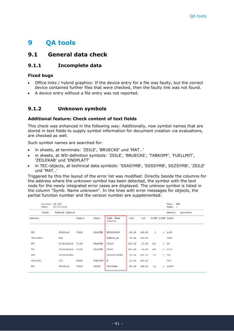
9.1.2 Unknown symbols
Additional feature: Check content of text fields
This check was enhanced in the following way: Additionally, now symbol names that are
stored in text fields to supply symbol information for document creation via evaluations,
are checked as well.
Such symbol names are searched for:
• in sheets, at terminals: 'ZEILE', 'BRUECKE' und 'MAT…'
• in sheets, at WD-definition symbols: 'ZEILE', 'BRUECKE', 'TABKOPF', 'FUELLMIT',
'ZEILEKAB' und 'ENDPLATT'
• in TEC-objects, at technical data symbols: 'SSASYMB', 'SSSSYMB', SSZSYMB', 'ZEILE'
und 'MAT…'
Triggered by this the layout of the error list was modified: Directly beside the columns for
the address where the unknown symbol has been detected, the symbol with the text
node for the newly integrated error cases are displayed. The unknow symbol is listed in
the column "Symb. Name unknown". In the lines with error messages for objects, the
partial function number and the version number are supplemented:

QA tools
- 42 -
9.2 Objects and devices
9.2.1 Device check
Changes
If via project settings ("Device Documents" / "Resource schedule") error messages con-
cerning TEC-objects are suppressed, then with the common start the marking of this
check is removed. If the comment entry field is empty, the text "Project settings: Mes-
sages conc. TEC are suppressed!" is entered. (The check can be activated before ac-
knowledging the mask.)
Fixed bug
Running in the context of the common start, this evaluation did not generate an addi-
tional information file, even if additional information did exist.
9.3 Symbols and designation
9.3.1 Item captioning
New feature
From now on corner symbols GJ512 for location polygons are listed as error if their des-
ignation in '=' or '+' differs from the title block resp. from the polygon.
Fixed bugs
• Running in the context of the common start, this evaluation did not generate an addi-
tional information file, even if additional information did exist.
• If this check was run as part of a common start, and if in the course of the evaluation
"common start" an old version of the status form sheets was deleted, the evaluation
aborted with this check ("Item captioning").
• A '+'-entry that was invisible and differed from the polygon or the title block, was not
reported as an error.
• Like the terminal / plug check the symbols without entry in '+' are reported too; the
header for the error number did not provide this information.

QA tools
- 43 -
9.3.2 Captioning of termin./plugs
New feature
The check of terminals and plugs now also checks entries of symbol names in text nodes
like 'ZEILE' or 'MAT1' on observance of the guidelines-rules. Therefore, the new error
code "1(0)" was implemented:
9.4 Connections and potentials
9.4.1 Faulty pot./cross ref. symb.
Change
References to a wiring material table were abolished (see chapter 6, "New workflow with
wiring material"). The check "Faulty pot. / cross ref. symb." was modified accordingly.

QA tools
- 44 -
9.5 Circuit dgr. accomp. docu.
9.5.1 Term.: circuit diagram terminal diagram
New feature 1
The terminal diagram check observes new fitting symbols for jumpers and separating
material which display that a jumper may cross a plate or a cover (see chapter 7.1, New
fittings for the terminal diagrams editing).
If a jumper crosses separating material, then this crossing is not reported as an error if
at least one of the two participating symbols is chosen from these new symbols (EXFQ*
for reducing jumpers, EXTQ* for separating material with gaps).
The following constellation in the terminal diagram:
does result in only one error message:
The error message "A(0)" now lists the terminal from which the jumper
starts, that is the lower of the two connected terminals!

QA tools
- 45 -
New feature 2
The terminal diagram now also examines the names of symbols in the terminal diagram
and checks these against guidelines-rules. Therefore, the new error code "9(0)" exists in
the error list:
In case of illicit line symbol names, in addition the error "C(0)" may be
reported because of its name the terminal line is not found as the corre-
sponding line for the terminal in the circuit diagram.
Fixed bug
For two adjacent terminal lines of different height it often occurred that the error "Jump-
er crossing partition element" was reported without reason.
9.5.2 Item definition resource schedules
Fixed bug
Running in the context of the common start, this evaluation did not generate an addi-
tional information file, even if additional information did exist.
9.5.3 All sheets list of documents
Fixed bug
If 2 sheets in a documentation carried identical ambiguity designations in the title block,
only one of these sheets was listed in the error list.
9.6 QS-tools acc. to previous versions
9.6.1 QS-tools acc. to EVU-module 2019
With EVU-module 2020 data can be checked with the state of the QS-tools of EVU-
module 2019; to this purpose the AWT library EVUQS2019U0_2020 was made available.

Reference data
- 46 -
10 Reference data
10.1 Symbols
10.1.1 New reference symbols
All reference symbols listed below were newly built for the symbol libraries
X002020/X002020_IEC and X0032 (German) as well as for the symbol libraries
X002020E/X002020E_IEC (English). Form sheet symbols were likewise supplemented in
X002020_FORM_STX and X002020_IEC_FORM_STX.
EXFQ* 24 new symbols as representations for reducing jumpers in terminal dia-
grams (see chapter 9.5.1, Term.: circuit diagram terminal diagram)
EXTQ* 19 new symbols as representations in terminal diagrams for separating
material that allows crossing jumpers (see chapter 9.5.1, Term.: circuit di-
agram terminal diagram)
GJ520 potential interruption symbol with complete identifying and describing
block (see chapter 7.2)
TJ710 header symbol for TEC-object W00000W0 (wiring material catalog, see
chapter 6)
TJ710B header symbol for TEC-object W00000W0 (wiring material catalog, see
chapter 6), small
TJ711 line symbol for TEC-object W00000W0 (wiring material catalog, see chap-
ter 6)
TJ711B line symbol for TEC-object W00000W0 (wiring material catalog, see chap-
ter 6), small
VQ400A new definition symbol for the cross-connection diagram: 'LPOS', 'LMAT',
'LQUER', 'LFARBE' removed (see chapter 6)
VQ500A new definition symbol for the cross-connection diagram (old form): 'LPOS',
'LMAT', 'LQUER', 'LFARBE' removed (see chapter 6)
VX400A new definition symbol for the terminal diagram: 'LPOS' removed (see chap-
ter 6)
10.1.2 Changes on reference symbols
If not specified otherwise, the changes listed below were performed for the symbols in
X002020/X002020_IEC and X0032 (German) as well as for the symbols in
X002020E/X002020E_IEC (English). Form sheet symbols were likewise changed in
X002020_FORM_STX and X002020_IEC_FORM_STX.
GJ522 colored blue (as optical difference to GJ512 = red)
GW701 'LPOS' pre-defined with "Wire", T&MAXTXL=20
GW701P ditto
GW702 ditto

Reference data
- 47 -
L002734* (logic mask for IX505, IX509, IX510) DIN only, no BSB: positions of
'GERAET' and '-AN' were switched; 'GERAET' got an automatic text move-
up to '-AN'
LQ010071* DIN only: 3rd connection point was added, located within the symbol at the
position of connection point 2 of the basic connector symbol
LQ010072* ditto
LQ010073* ditto
LQ02231* ditto
LQ0223I1* ditto
M_EX4 new symbols EXFQ* for reducing jumpers entered (see chapter 10.1.1)
M_EX5 new symbols EXTQ* entered separating material that allows crossing
jumpers (see chapter 10.1.1)
M_W new potential interruption symbol GJ520 entered (see chapter 7.2)
QR001 text node 'RASGRASC' for a scaling factor supplemented
UJ018 IEC only: reference designation IDs re-arranged: '-' in the left upper cor-
ner, 'STE' to the right of '-', '=' and '+' above, outside the rectangle
UJ032 ditto
UJ034 ditto
UJ062 IEC only: reference designation IDs re-arranged: '-' in the left upper cor-
ner, 'STE' to the right of '-', '=' and '+' still further to the right
UJ092 ditto
UJ124 ditto
UJ180 ditto
VB281TD text nodes for network texts removed ('NN*', 'NPOSI*,.'NM*', 'NQ*', 'NF*',
'SICHT')
VQ400 OLD: replaced by VQ400A
VQ500 OLD: replaced by VQ500A
VR560 DIN + IEC/ENG: bothering and unnecessary vertical line in the block for
the assignment was removed
VR561 ditto
VR562 ditto
VR563 ditto
VX400 OLD: replaced by VX400A
VX710 new text node supplemented for marking an optional wiring material table
(see chapter 6)
VX710B ditto
WJPRU_* the feature "wire mat. unknown" was removed from the menu (see chapter
6)

Reference data
- 48 -
10.2 Sheets
10.2.1 New sheets
If not specified otherwise, the form sheets listed below were newly created in
X002020/X002020_IEC (German) as well as in X002020E/X002020E_IEC (English).
VDR2019,
VDR2019_KKS
VP, VP_F QS status sheets for the previous version, usable with
EVU-module 2020, were made available
10.2.2 Changes on form sheets
If not specified otherwise, the changes listed below were performed for the sheets in
X002020/X002020_IEC (German) as well as for the sheets in X002020E/X002020E_IEC
(English).
VDR, VDR_KKS GV1 DIN only: the setting values for network texts
(N&NETNAM and wiring material information) were re-
moved; see also 10.1.2, symbol VB281TD.
VDR, VDR_KKS VL In the sort symbol the 5th sort was switched from POSI
(wiring material position number) to LMAT (wiring mate-
rial (complete)).
VDRvvv,
VDRvvv_KKS
VP, VP_F QS status sheets for older QS-versions were adapted to
EVU-module 2020