Embed Size (px)
Citation preview
FORM NO. R22-858
Package Gas ElectricRKKL-B Series
Rely on Ruud.™
RKKL-B Standard Efficiency SeriesNominal Sizes 7.5, 10 & 12.5 Tons[26.4, 35.2 & 44.0 kW]ASHRAE 90.1-2010 Compliant Models
Ruud Commercial Value SeriesPackage Gas Electric UnitRuud Commercial Value SeriesPackage Gas Electric Unit
Unit shown with optional louvered coil protection.
“Proper sizing and installation of equipment is critical toachieve optimal performance. Ask your Contractor for detailsor visit www.energystar.gov.”
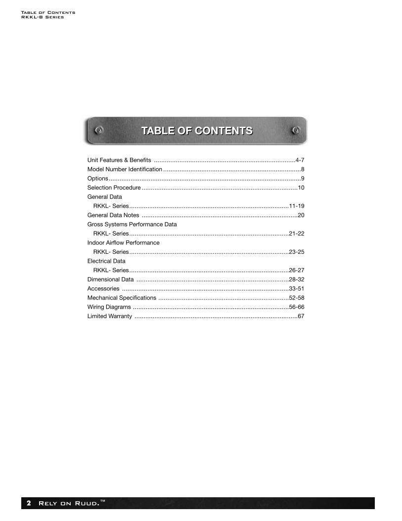
Table of ContentsRKKL-B Series
Rely on Ruud.™2
Unit Features & Benefits ..............................................................................4-7
Model Number Identification ............................................................................8
Options..........................................................................................................9
Selection Procedure ......................................................................................10
General Data
RKKL- Series........................................................................................11-19
General Data Notes ......................................................................................20
Gross Systems Performance Data
RKKL- Series........................................................................................21-22
Indoor Airflow Performance
RKKL- Series........................................................................................23-25
Electrical Data
RKKL- Series........................................................................................26-27
Dimensional Data ....................................................................................28-32
Accessories ............................................................................................33-51
Mechanical Specifications ........................................................................52-58
Wiring Diagrams ......................................................................................56-66
Limited Warranty ..........................................................................................67
TABLE OF CONTENTSTABLE OF CONTENTS

Unit Features & BenefitsRKKL-B Series
Rely on Ruud.™ 3
• R-410A HFC refrigerant.• Complete factory charged, wired and run tested.• Scroll compressors with internal line break overload and
high-pressure protection.• Single stage compressor on 7.5 and 10 Ton models. • Two stage compressor on 12.5 ton model.• Convertible airflow.• Fixed restriction refrigerant flow control on 7.5 and 10 ton
models.• TXV on 12.5 ton model.• High Pressure and Low Pressure/Loss of charge protection
standard on all models.• Solid Core liquid line filter drier on each circuit.• Single slab, single pass designed evaporator and condenser
coils facilitate easy cleaning for maintained high efficiencies.• Cooling operation up to 125 degree F ambient.• MicroChannel Outdoor Coils.• Foil faced insulation encapsulated throughout entire unit
minimizes airborne fibers from the air stream.• Access door with heavy-duty gasketing, and mechanically
attached with 5/16" screws.• Slide Out Indoor fan assembly for added service
convenience.• Powder Paint Finish meets ASTMB117 steel coated on each
side for maximum protection. G90 galvanized.
• One piece top cover and one piece base pan with drawnsupply and return opening for superior water management.
• Forkable base rails for easy handling and lifting.• Single point electrical and gas connections.• Internally sloped slide out condensate pan conforms to
ASHRAE 62 standards.• High performance belt drive motor with variable pitch pulleys
and quick adjust belt system.• Permanently lubricated evaporator, condenser and gas heat
inducer motors.• Condenser motors are internally protected, totally enclosed
with shaft down design.• 2 inch filter standard with slide out design.• Two stage gas valve, direct spark ignition, and induced draft
for efficiency and reliability.• Tubular heat exchange for long life and induced draft for
efficiency and reliability.• Solid state furnace control with on board diagnostics.• 24 volt control system with resettable circuit breakers.• Colored and labeled wiring.• Copper tube/Aluminum Fin coils (121/2 uses MicroChannel
condenser).• Molded compressor plug.
RKKL-B STANDARD FEATURES INCLUDE:
Unit Features & BenefitsRKKL-B Series
Rely on Ruud.™4
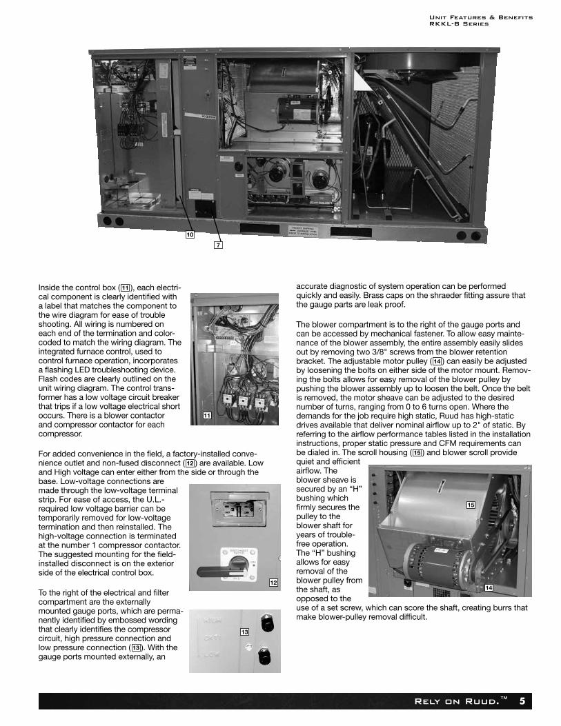
Ruud Package equipment is designed from the ground upwith the latest features and benefits required to compete intoday’s market. The clean design stands alone in the industryand is a testament to the quality, reliability, ease of installationand ser vice ability that goes into each unit. Outwardly, the largeRuud Commercial Series™ label ( ) identifies the brand tothe customer.
The sheet-metal cabinet ( ) uses nothing less than 18-gaugematerial for structural components with an underlying coat of G90. To ensure the leak-proof integrity of these units, the designutilizes a one-piece top with a 1/8" drip lip ( ), gasket-protectedpanels and screws. The Ruud hail guard ( ) (optional) is itstrademark, and sets the standard for coil protection in the indus-try. Every Ruud package unit uses the toughest finish in theindustry, using electro deposition baked-on enamel tested towithstand a rigorous 1000-hour salt spray test, per ASTM B117.
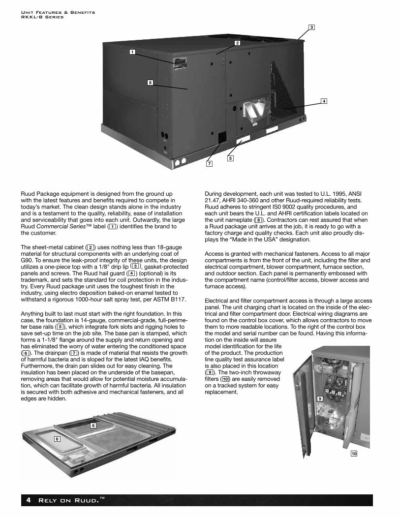
Anything built to last must start with the right foundation. In thiscase, the foundation is 14-gauge, commercial-grade, full-perime -ter base rails ( ), which integrate fork slots and rigging holes tosave set-up time on the job site. The base pan is stamped, whichforms a 1-1/8" flange around the supply and return opening andhas eliminated the worry of water entering the conditioned space( ). The drainpan ( ) is made of material that resists the growthof harmful bacteria and is sloped for the latest IAQ benefits. Furthermore, the drain pan slides out for easy cleaning. The insulation has been placed on the underside of the basepan,removing areas that would allow for potential moisture accumula-tion, which can facilitate growth of harmful bacteria. All insulationis secured with both adhesive and mechanical fasteners, and alledges are hidden.
During development, each unit was tested to U.L. 1995, ANSI21.47, AHRI 340-360 and other Ruud-required reliability tests.Ruud adheres to stringent IS0 9002 quality procedures, andeach unit bears the U.L. and AHRI certification labels located on the unit nameplate ( ). Contractors can rest assured that when a Ruud package unit arrives at the job, it is ready to go with afactory charge and quality checks. Each unit also proudly dis -plays the “Made in the USA” designation.
Access is granted with mechanical fasteners. Access to all majorcompartments is from the front of the unit, including the filter andelectrical compartment, blower compartment, furnace section,and outdoor section. Each panel is permanently embossed withthe compartment name (control/filter access, blower access andfurnace access).
Electrical and filter compartment access is through a large accesspanel. The unit charging chart is located on the inside of the elec-trical and filter compartment door. Electrical wiring diagrams arefound on the control box cover, which allows contractors to movethem to more readable locations. To the right of the control boxthe model and serial number can be found. Having this informa-tion on the inside will assuremodel identification for the lifeof the product. The productionline quality test assurance labelis also placed in this location( ). The two-inch throwawayfilters ( ) are easily removedon a tracked system for easyreplacement.
1
2
3
4
5
76
8
9
10
6
6
9
10
2
8
1
3
57
4
Unit Features & BenefitsRKKL-B Series
Rely on Ruud.™ 5
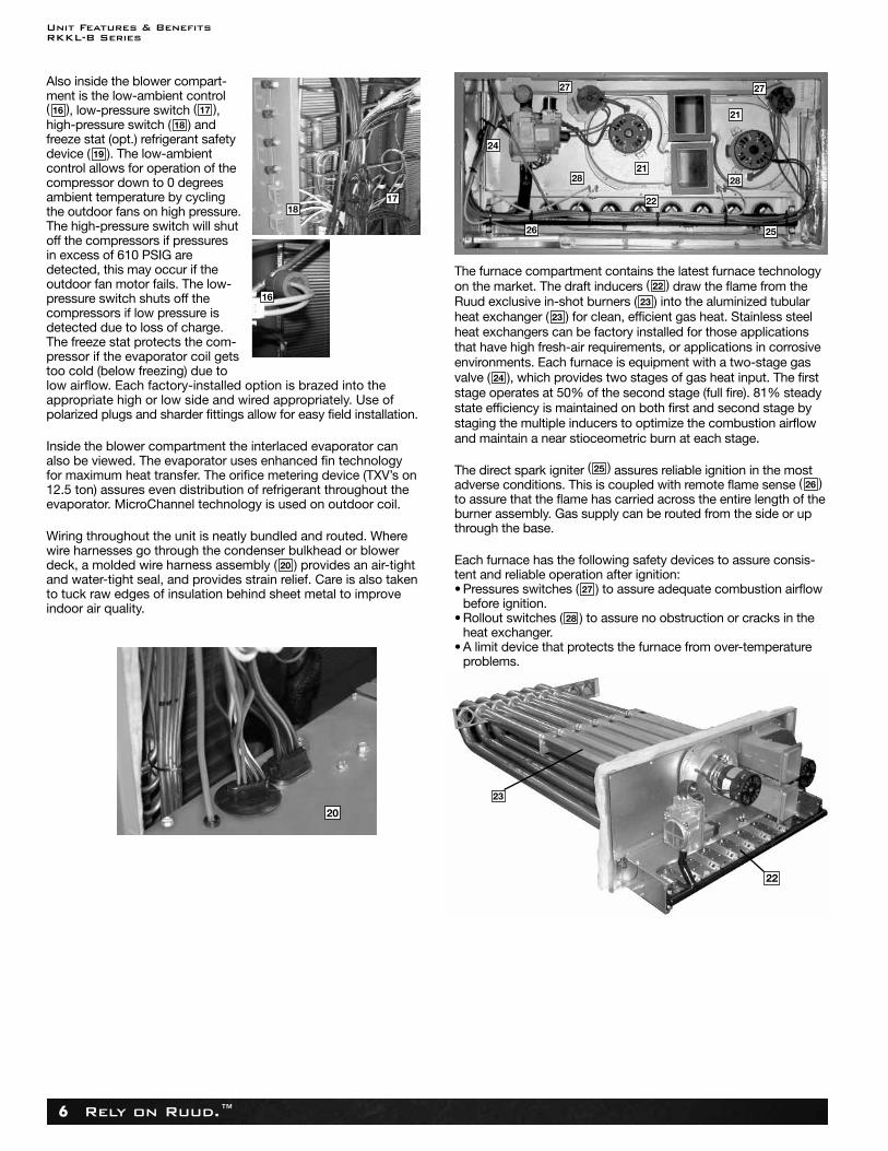
Inside the control box ( ), each electri-cal component is clearly identified with a label that matches the component tothe wire diagram for ease of troubleshooting. All wiring is numbered on each end of the termination and color-coded to match the wiring diagram. Theintegrated furnace control, used tocontrol furnace operation, incorporatesa flashing LED troubleshooting device.Flash codes are clearly outlined on theunit wiring diagram. The control trans-former has a low voltage circuit breakerthat trips if a low voltage electrical shortoccurs. There is a blower contactor and compressor contactor for eachcompressor.
For added convenience in the field, a factory-installed conve-nience outlet and non-fused disconnect ( ) are available. Lowand High voltage can enter either from the side or through thebase. Low-voltage connections aremade through the low-voltage terminalstrip. For ease of access, the U.L.-required low voltage barrier can betemporarily removed for low-voltagetermination and then reinstalled. Thehigh-voltage connection is terminatedat the number 1 compressor contactor.The suggested mounting for the field-installed disconnect is on the exteriorside of the electrical control box.
To the right of the electrical and filtercompartment are the externally mounted gauge ports, which are perma-nently identified by embossed wordingthat clearly identifies the compressorcircuit, high pressure connection andlow pressure connection ( ). With thegauge ports mounted externally, an
accurate diagnostic of system operation can be performedquickly and easily. Brass caps on the shraeder fitting assure thatthe gauge parts are leak proof.
The blower compartment is to the right of the gauge ports and can be accessed by mechanical fastener. To allow easy mainte-nance of the blower assembly, the entire assembly easily slidesout by removing two 3/8" screws from the blower retentionbracket. The adjustable motor pulley ( ) can easily be adjustedby loosening the bolts on either side of the motor mount. Remov-ing the bolts allows for easy removal of the blower pulley bypushing the blower assembly up to loosen the belt. Once the beltis removed, the motor sheave can be adjusted to the desirednumber of turns, ranging from 0 to 6 turns open. Where thedemands for the job require high static, Ruud has high-staticdrives available that deliver nominal airflow up to 2" of static. Byreferring to the airflow performance tables listed in the installationinstructions, proper static pressure and CFM requirements canbe dialed in. The scroll housing ( ) and blower scroll providequiet and efficientairflow. Theblower sheave issecured by an “H”bushing whichfirmly secures thepulley to theblower shaft foryears of trouble-free operation.The “H” bushingallows for easyremoval of theblower pulley fromthe shaft, asopposed to theuse of a set screw, which can score the shaft, creating burrs thatmake blower-pulley removal difficult.
15
14
13
12
11
10
7
13
11
1214
15
Unit Features & BenefitsRKKL-B Series
Rely on Ruud.™6
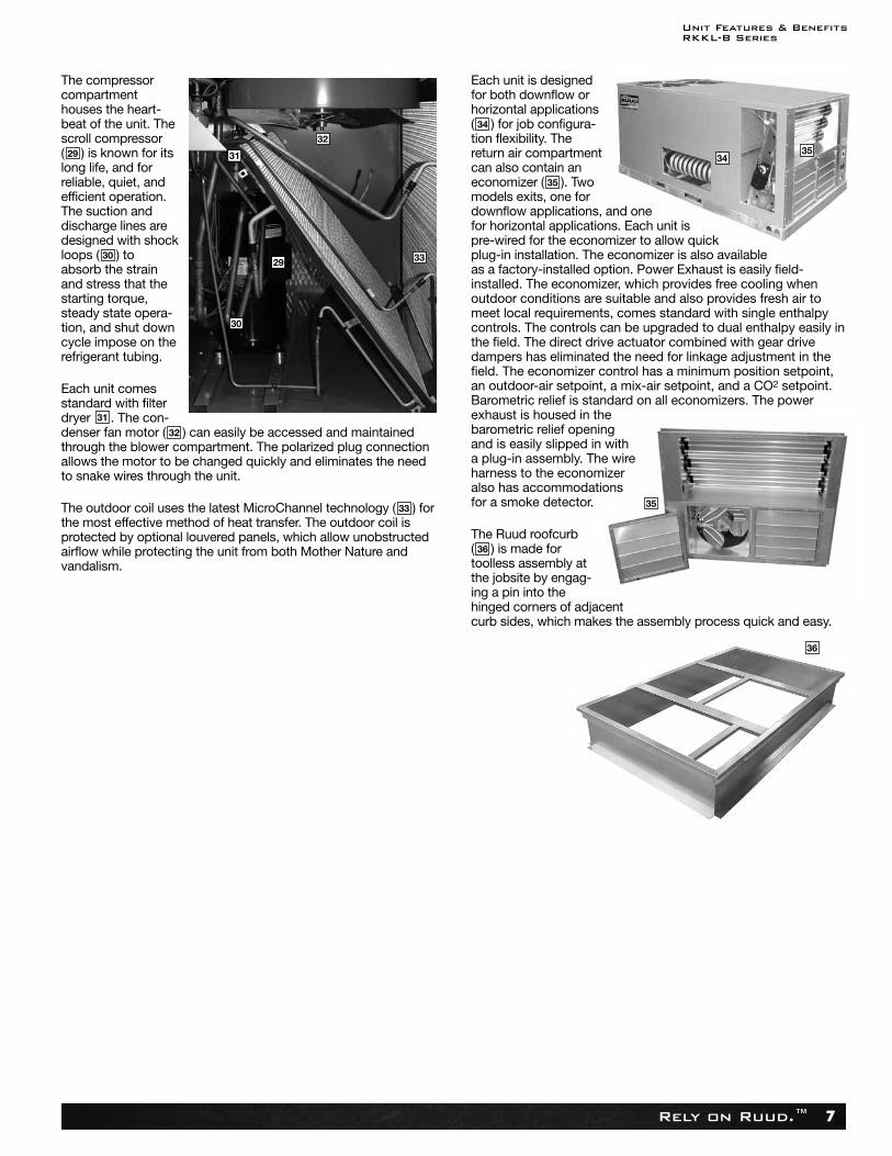
Also inside the blower compart-ment is the low-ambient control( ), low-pressure switch ( ),high-pressure switch ( ) andfreeze stat (opt.) refrigerant safetydevice ( ). The low-ambientcontrol allows for operation of thecompressor down to 0 degreesambient temperature by cyclingthe outdoor fans on high pressure.The high-pressure switch will shutoff the compressors if pressuresin excess of 610 PSIG aredetected, this may occur if theoutdoor fan motor fails. The low-pressure switch shuts off thecompressors if low pressure isdetected due to loss of charge.The freeze stat protects the com-pressor if the evapora tor coil getstoo cold (below freezing) due tolow airflow. Each factory-installed option is brazed into theappropriate high or low side and wired appropriately. Use ofpolarized plugs and sharder fittings allow for easy field installation.
Inside the blower compartment the interlaced evaporator canalso be viewed. The evaporator uses enhanced fin technology for maximum heat transfer. The orifice metering device (TXV’s on12.5 ton) assures even distribution of refrigerant throughout theevaporator. MicroChannel technology is used on outdoor coil.
Wiring throughout the unit is neatly bundled and routed. Wherewire harnesses go through the condenser bulkhead or blowerdeck, a molded wire harness assembly ( ) provides an air-tightand water-tight seal, and provides strain relief. Care is also takento tuck raw edges of insulation behind sheet metal to improveindoor air quality.
The furnace compartment contains the latest furnace technologyon the market. The draft inducers ( ) draw the flame from the Ruud exclusive in-shot burners ( ) into the aluminized tubularheat exchanger ( ) for clean, efficient gas heat. Stainless steelheat exchangers can be factory installed for those applicationsthat have high fresh-air requirements, or applications in corrosiveenvironments. Each furnace is equipment with a two-stage gasvalve ( ), which provides two stages of gas heat input. The firststage operates at 50% of the second stage (full fire). 81% steadystate efficiency is maintained on both first and second stage bystaging the multiple inducers to optimize the combustion airflowand maintain a near stioceometric burn at each stage.
The direct spark igniter ( ) assures reliable ignition in the mostadverse conditions. This is coupled with remote flame sense ( )to assure that the flame has carried across the entire length of theburner assembly. Gas supply can be routed from the side or upthrough the base.
Each furnace has the following safety devices to assure consis-tent and reliable operation after ignition: • Pressures switches ( ) to assure adequate combustion airflow
before ignition. • Rollout switches ( ) to assure no obstruction or cracks in the
heat exchanger.• A limit device that protects the furnace from over-temperature
problems.
28
27
26
25
24
23
16
20
19
18
17
22
23
18
16
24
21
21
26
27 27
25
28 28
22
23
22
17
20
Unit Features & BenefitsRKKL-B Series
Rely on Ruud.™ 7
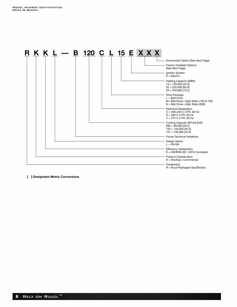
The compressorcompartmenthouses the heart-beat of the unit. Thescroll compressor( ) is known for itslong life, and forreliable, quiet, andefficient operation.The suction anddischarge lines aredesigned with shockloops ( ) to absorb the strainand stress that thestarting torque,steady state opera-tion, and shut downcycle impose on therefrigerant tubing.
Each unit comesstandard with filterdryer . The con-denser fan motor ( ) can easily be accessed and maintainedthrough the blower compartment. The polarized plug connectionallows the motor to be changed quickly and eliminates the needto snake wires through the unit.
The outdoor coil uses the latest MicroChannel technology ( ) forthe most effective method of heat transfer. The outdoor coil isprotected by optional louvered panels, which allow unobstructedairflow while protecting the unit from both Mother Nature andvandalism.
Each unit is designedfor both downflow orhorizontal applications( ) for job configura-tion flexibility. Thereturn air compartmentcan also contain aneconomizer ( ). Twomodels exits, one for downflow applications, and onefor horizontal applications. Each unit ispre-wired for the economizer to allow quickplug-in installation. The economizer is also availableas a factory-installed option. Power Exhaust is easily field-installed. The economizer, which provides free cooling whenoutdoor conditions are suitable and also provides fresh air tomeet local requirements, comes standard with single enthalpycontrols. The controls can be upgraded to dual enthalpy easily inthe field. The direct drive actuator combined with gear drivedampers has eliminated the need for linkage adjustment in thefield. The economizer control has a minimum position setpoint,an outdoor-air setpoint, a mix-air setpoint, and a CO2 setpoint.Barometric relief is standard on all economizers. The powerexhaust is housed in thebarometric relief openingand is easily slipped in with a plug-in assembly. The wireharness to the economizeralso has accommodations for a smoke detector.
The Ruud roofcurb( ) is made fortoolless assembly atthe jobsite by engag-ing a pin into thehinged corners of adjacentcurb sides, which makes the assembly process quick and easy.
31
36
35
34
33
32
30
29
29
32
33
36
35
3534
30
31
Model Number IdentificationRKKL-B Series
Rely on Ruud.™8
R K K L — B 120 C L 15 E X X XEconomizer Option (See Next Page)
Factory Installed Options (See Next Page)
Ignition SystemE = Electric
Heating Capacity (MBH)15 = 150,000 [44.0]22 = 225,000 [65.9]25 = 250,000 [73.2]
Drive PackageL = Belt DriveM= Belt Drive—High Static (120 & 150)N = Belt Drive—High Static (090)
Electrical DesignationC = 208-230 V, 3 PH, 60 HzD = 460 V, 3 PH, 60 HzY = 575 V, 3 PH, 60 Hz
Cooling Capacity (BTUH) [kW]090 = 90,000 [26.4]120 = 120,000 [35.2]151 = 150,000 [44.0]
Future Technical Variations
Design SeriesL = R410A
Efficiency DesignationK = ASHRAE 90.1-2010 Compliant
Product ClassificationK = Rooftop—Commercial
TradebrandR = Ruud Packaged Gas/Electric
[ ] Designates Metric Conversions
Selection ProcedureRKKL-B Series
Rely on Ruud.™ 9
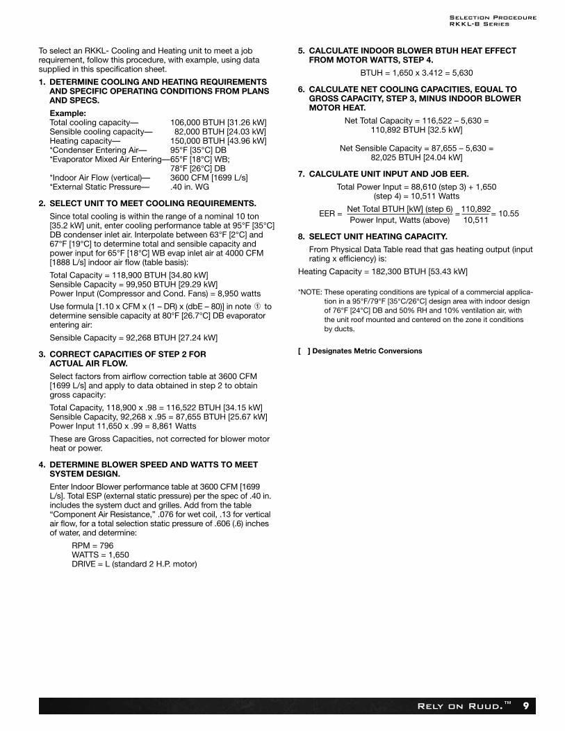
To select an RKKL- Cooling and Heating unit to meet a jobrequirement, follow this procedure, with example, using data supplied in this specification sheet.
1. DETERMINE COOLING AND HEATING REQUIREMENTSAND SPECIFIC OPERATING CONDITIONS FROM PLANSAND SPECS.
Example:Total cooling capacity— 106,000 BTUH [31.26 kW]Sensible cooling capacity— 82,000 BTUH [24.03 kW]Heating capacity— 150,000 BTUH [43.96 kW]*Condenser Entering Air— 95°F [35°C] DB*Evaporator Mixed Air Entering—65°F [18°C] WB;
78°F [26°C] DB*Indoor Air Flow (vertical)— 3600 CFM [1699 L/s]*External Static Pressure— .40 in. WG
2. SELECT UNIT TO MEET COOLING REQUIREMENTS.
Since total cooling is within the range of a nominal 10 ton[35.2 kW] unit, enter cooling performance table at 95°F [35°C]DB condenser inlet air. Interpolate between 63°F [2°C] and67°F [19°C] to determine total and sensible capacity andpower input for 65°F [18°C] WB evap inlet air at 4000 CFM[1888 L/s] indoor air flow (table basis):
Total Capacity = 118,900 BTUH [34.80 kW]Sensible Capacity = 99,950 BTUH [29.29 kW]Power Input (Compressor and Cond. Fans) = 8,950 watts
Use formula [1.10 x CFM x (1 – DR) x (dbE – 80)] in note todetermine sensible capacity at 80°F [26.7°C] DB evaporatorentering air:
Sensible Capacity = 92,268 BTUH [27.24 kW]
3. CORRECT CAPACITIES OF STEP 2 FORACTUAL AIR FLOW.
Select factors from airflow correction table at 3600 CFM [1699 L/s] and apply to data obtained in step 2 to obtain gross capacity:
Total Capacity, 118,900 x .98 = 116,522 BTUH [34.15 kW]Sensible Capacity, 92,268 x .95 = 87,655 BTUH [25.67 kW]Power Input 11,650 x .99 = 8,861 Watts
These are Gross Capacities, not corrected for blower motorheat or power.
4. DETERMINE BLOWER SPEED AND WATTS TO MEET SYSTEM DESIGN.
Enter Indoor Blower performance table at 3600 CFM [1699L/s]. Total ESP (external static pressure) per the spec of .40 in.includes the system duct and grilles. Add from the table“Component Air Resistance,” .076 for wet coil, .13 for verticalair flow, for a total selection static pressure of .606 (.6) inchesof water, and determine:
RPM = 796WATTS = 1,650DRIVE = L (standard 2 H.P. motor)
5. CALCULATE INDOOR BLOWER BTUH HEAT EFFECTFROM MOTOR WATTS, STEP 4.
BTUH = 1,650 x 3.412 = 5,630
6. CALCULATE NET COOLING CAPACITIES, EQUAL TOGROSS CAPACITY, STEP 3, MINUS INDOOR BLOWERMOTOR HEAT.
Net Total Capacity = 116,522 – 5,630 =110,892 BTUH [32.5 kW]
Net Sensible Capacity = 87,655 – 5,630 =82,025 BTUH [24.04 kW]
7. CALCULATE UNIT INPUT AND JOB EER.
Total Power Input = 88,610 (step 3) + 1,650(step 4) = 10,511 Watts
EER = Net Total BTUH [kW] (step 6) =110,892= 10.55Power Input, Watts (above) 10,511
8. SELECT UNIT HEATING CAPACITY.
From Physical Data Table read that gas heating output (inputrating x efficiency) is:
Heating Capacity = 182,300 BTUH [53.43 kW]
*NOTE: These operating conditions are typical of a commercial applica-tion in a 95°F/79°F [35°C/26°C] design area with indoor designof 76°F [24°C] DB and 50% RH and 10% ventilation air, with the unit roof mounted and centered on the zone it conditions by ducts.
[ ] Designates Metric Conversions
OptionsRKKL-B Series
Rely on Ruud.™10
Option Code HailGuard
Non-Powered ConvenienceOutlet/Unfused
Service Disconnect
Low Ambient/Freeze
StatAD x
StainlessSteel
Heat Exchanger
AH x
x
x
BG x
DN x x x
x
AP x
x
BY x x
CR x x
AJ
BF x x
xJB x
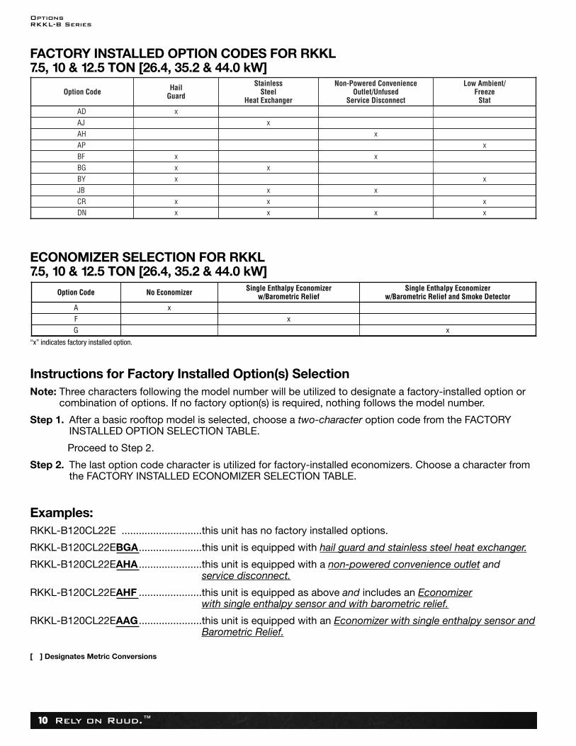
FACTORY INSTALLED OPTION CODES FOR RKKL 7.5, 10 & 12.5 TON [26.4, 35.2 & 44.0 kW]
Option Code No Economizer Single Enthalpy Economizer w/Barometric Relief and Smoke Detector
A xF
Single Enthalpy Economizerw/Barometric Relief
xG x
ECONOMIZER SELECTION FOR RKKL 7.5, 10 & 12.5 TON [26.4, 35.2 & 44.0 kW]
“x” indicates factory installed option.
Instructions for Factory Installed Option(s) SelectionNote: Three characters following the model number will be utilized to designate a factory-installed option or
combination of options. If no factory option(s) is required, nothing follows the model number.
Step 1. After a basic rooftop model is selected, choose a two-character option code from the FACTORYINSTALLED OPTION SELECTION TABLE.
Proceed to Step 2.
Step 2. The last option code character is utilized for factory-installed economizers. Choose a character fromthe FACTORY INSTALLED ECONOMIZER SELECTION TABLE.
Examples:RKKL-B120CL22E ............................this unit has no factory installed options.
RKKL-B120CL22EBGA......................this unit is equipped with hail guard and stainless steel heat exchanger.
RKKL-B120CL22EAHA ......................this unit is equipped with a non-powered convenience outlet and service disconnect.
RKKL-B120CL22EAHF ......................this unit is equipped as above and includes an Economizerwith single enthalpy sensor and with barometric relief.
RKKL-B120CL22EAAG......................this unit is equipped with an Economizer with single enthalpy sensor andBarometric Relief.
[ ] Designates Metric Conversions
General DataRKKL-B Series
Rely on Ruud.™ 11
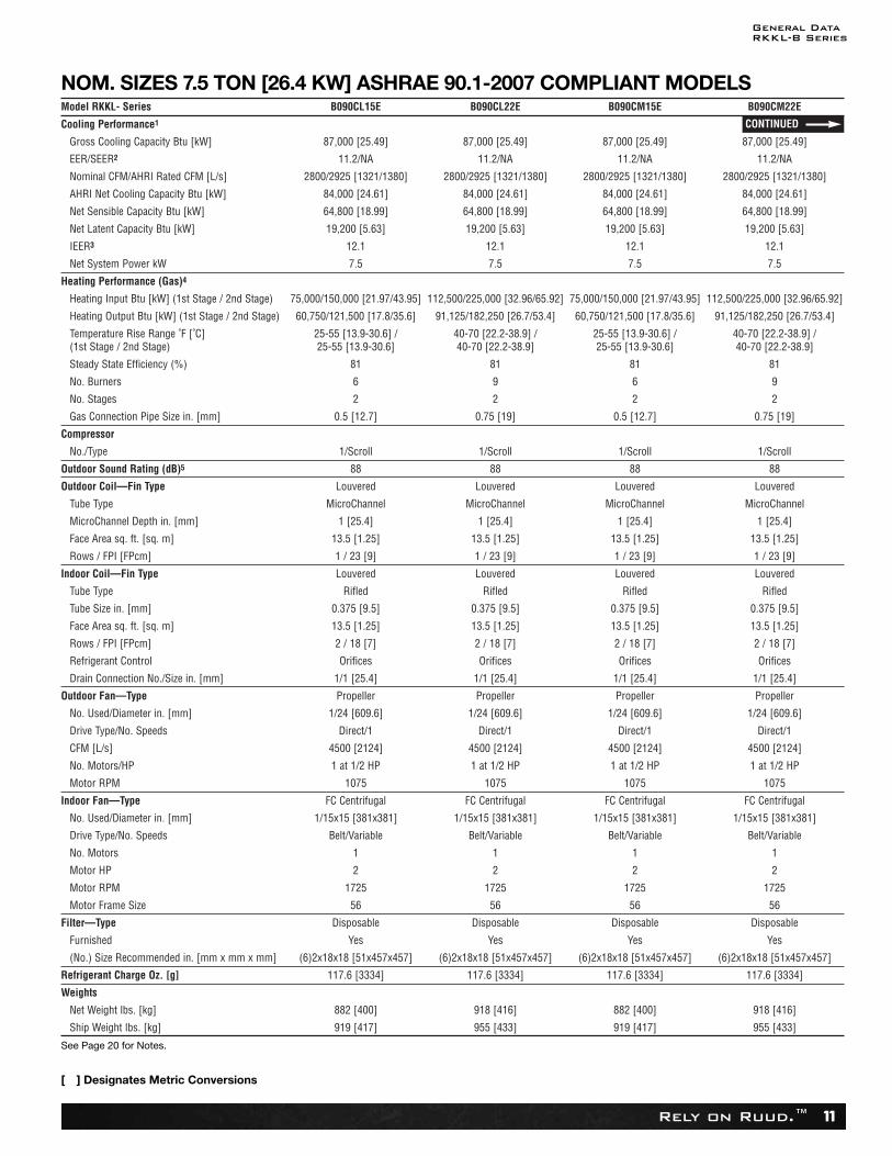
NOM. SIZES 7.5 TON [26.4 KW] ASHRAE 90.1-2007 COMPLIANT MODELS
See Page 20 for Notes.
[ ] Designates Metric Conversions
Model RKKL- Series B090CL15E B090CL22E B090CM15E B090CM22E
Cooling Performance1
Gross Cooling Capacity Btu [kW] 87,000 [25.49] 87,000 [25.49] 87,000 [25.49] 87,000 [25.49]
EER/SEER2 11.2/NA 11.2/NA 11.2/NA 11.2/NA
Nominal CFM/AHRI Rated CFM [L/s] 2800/2925 [1321/1380] 2800/2925 [1321/1380] 2800/2925 [1321/1380] 2800/2925 [1321/1380]
AHRI Net Cooling Capacity Btu [kW] 84,000 [24.61] 84,000 [24.61] 84,000 [24.61] 84,000 [24.61]
Net Sensible Capacity Btu [kW] 64,800 [18.99] 64,800 [18.99] 64,800 [18.99] 64,800 [18.99]
Net System Power kW 7.5 7.5 7.5 7.5
Heating Performance (Gas)4
Heating Input Btu [kW] (1st Stage / 2nd Stage) 75,000/150,000 [21.97/43.95] 112,500/225,000 [32.96/65.92] 75,000/150,000 [21.97/43.95] 112,500/225,000 [32.96/65.92]
Heating Output Btu [kW] (1st Stage / 2nd Stage) 60,750/121,500 [17.8/35.6] 91,125/182,250 [26.7/53.4] 60,750/121,500 [17.8/35.6] 91,125/182,250 [26.7/53.4]
Temperature Rise Range ˚F [˚C](1st Stage / 2nd Stage)
25-55 [13.9-30.6] / 25-55 [13.9-30.6]
40-70 [22.2-38.9] /40-70 [22.2-38.9]
25-55 [13.9-30.6] / 25-55 [13.9-30.6]
40-70 [22.2-38.9] /40-70 [22.2-38.9]
Net Weight lbs. [kg] 882 [400] 918 [416] 882 [400] 918 [416]
Steady State Efficiency (%) 81 81 81 81
IEER3 12.1 12.1 12.1 12.1
No. Burners 6 9 6 9
No. Stages 2 2 2 2
Gas Connection Pipe Size in. [mm] 0.5 [12.7] 0.75 [19] 0.5 [12.7] 0.75 [19]
Compressor
No./Type 1/Scroll 1/Scroll 1/Scroll 1/Scroll
Outdoor Sound Rating (dB)5 88 88 88 88
Outdoor Coil—Fin Type Louvered Louvered Louvered Louvered
Tube Type MicroChannel MicroChannel MicroChannel MicroChannel
MicroChannel Depth in. [mm] 1 [25.4] 1 [25.4] 1 [25.4] 1 [25.4]
Face Area sq. ft. [sq. m] 13.5 [1.25] 13.5 [1.25] 13.5 [1.25] 13.5 [1.25]
Rows / FPI [FPcm] 1 / 23 [9] 1 / 23 [9] 1 / 23 [9] 1 / 23 [9]
Net Latent Capacity Btu [kW] 19,200 [5.63] 19,200 [5.63] 19,200 [5.63] 19,200 [5.63]
Indoor Coil—Fin Type Louvered Louvered Louvered Louvered
Tube Type Rifled Rifled Rifled Rifled
Tube Size in. [mm] 0.375 [9.5] 0.375 [9.5] 0.375 [9.5] 0.375 [9.5]
Face Area sq. ft. [sq. m] 13.5 [1.25] 13.5 [1.25] 13.5 [1.25] 13.5 [1.25]
Rows / FPI [FPcm] 2 / 18 [7] 2 / 18 [7] 2 / 18 [7] 2 / 18 [7]
Refrigerant Control Orifices Orifices Orifices Orifices
Drain Connection No./Size in. [mm] 1/1 [25.4] 1/1 [25.4] 1/1 [25.4] 1/1 [25.4]
Outdoor Fan—Type Propeller Propeller Propeller Propeller
No. Used/Diameter in. [mm] 1/24 [609.6] 1/24 [609.6] 1/24 [609.6] 1/24 [609.6]
Drive Type/No. Speeds Direct/1 Direct/1 Direct/1 Direct/1
CFM [L/s] 4500 [2124] 4500 [2124] 4500 [2124] 4500 [2124]
No. Motors/HP 1 at 1/2 HP 1 at 1/2 HP 1 at 1/2 HP 1 at 1/2 HP
Motor RPM 1075 1075 1075 1075
Indoor Fan—Type FC Centrifugal FC Centrifugal FC Centrifugal FC Centrifugal
No. Used/Diameter in. [mm] 1/15x15 [381x381] 1/15x15 [381x381] 1/15x15 [381x381] 1/15x15 [381x381]
Drive Type/No. Speeds Belt/Variable Belt/Variable Belt/Variable Belt/Variable
No. Motors 1 1 1 1
Motor HP 2 2 2 2
Motor RPM 1725 1725 1725 1725
Motor Frame Size 56 56 56 56
Filter—Type Disposable Disposable Disposable Disposable
Furnished Yes Yes Yes Yes
(No.) Size Recommended in. [mm x mm x mm] (6)2x18x18 [51x457x457] (6)2x18x18 [51x457x457] (6)2x18x18 [51x457x457] (6)2x18x18 [51x457x457]
Refrigerant Charge Oz. [g] 117.6 [3334] 117.6 [3334] 117.6 [3334] 117.6 [3334]
Weights
Ship Weight lbs. [kg] 919 [417] 955 [433] 919 [417] 955 [433]
CONTINUED
Electrical DataRKKL-B Series
Rely on Ruud.™26
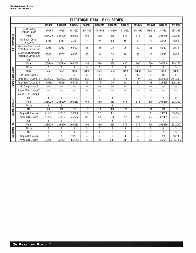
ELECTRICAL DATA – RKKL SERIES
Amps (LRA, each) 56/56 56/56 74.5/74.5
Volts
Minimum OvercurrentProtection Device Size
208/230
50/50
28
Maximum OvercurrentProtection Device Size 60/60
Com
pres
sor M
otor
No. 1
38.1
Volts 200/240
19
Phase 3RPM 3450
Amps (RLA), Comp. 1 23.2/23.2
HP, Compressor 2 —
Minimum CircuitAmpacity
Amps (LLA), Comp 2
Unit
Info
rmat
ion
Unit OperatingVoltage Range
—
187-253
Cond
ense
r Mot
or
No. 1
40/40
Volts 208/230
40/40
Phase 1
45/45
HP 1/2
20
Amps (FLA, each) 2.3/2.3
23
Amps (LRA, each) 5.6/5.6
Evap
orat
or F
an
No. 1
15
Volts 208/230Phase 3
HP 2Amps (FLA, each) 8/8
Amps (RLA), Comp 2 — — — — — —
8/823
208/2301
5.6/5.62.3/2.3
1/21
208/2301
—
—
23.2/23.2
34503
200/2401
60/60
50/50
208/230
187-253
Amps (LRA), Comp. 1
13/1333
208/2301
5.6/5.62.3/2.3
1/21
208/2301
—
—
23.2/23.2
34503
200/2401
60/60
60/60
208/230
187-253
164/164 164/164 164/164
423
4601
3.11.51/21
4601
—
—
11.2
34503
4801
30
25
460
414-506
75 75 54
733
4601
3.11.51/21
4601
—
—
11.2
34503
4801
30
30
460
414-506
423
5751
2.21
1/21
5751
—
—
7.9
34503
6001
20
20
575
518-632
HP, Compressor 1 6 6 6 6 6 6
B090CL B090CM B090CN B090DL B090DN B090YM
20
19
—
54
833
5751
2.21
1/21
5751
—
—
7.9
34503
6001
25
25
575
518-632
6
B090YN
19
15
—
54
423
5751
2.21
1/21
5751
—
—
7.9
34503
6001
20
20
575
518-632
6
B090YL
28
20
—
423
4601
3.11.51/21
4601
—
—
11.2
34503
4801
30
25
460
414-506
75
6
B090DM
74.5/74.5
56/56
—
225/225
13/1333
208/2301
4.7/4.72.4/2.4
1/31
208/2302—
—
30.1/30.1
34503
200/2401
80/80
70/70
208/230
187-253
10
B120CM
56/56
51/51
—
225/225
8/823
208/2301
4.7/4.72.4/2.4
1/31
208/2302
—
—
30.1/30.1
34503
200/2401
80/80
60/60
208/230
187-253
10
B120CL

Mechanical SpecificationsRKKL-B Series
Rely on Ruud.™54
23 81 19.13.G. Electrical Requirements1. Main power supply voltage, phase, and frequency must match those required by the manufacturer.
23 81 19.13.H. Unit Cabinet1. Unit cabinet shall be constructed of galvanized steel.2. Unit cabinet exterior paint shall be: powder coat paint.3. Evaporator fan compartment interior cabinet insulation shall conform to AHRI Standards 210 or 360 minimum exterior sweat
criteria. Interior surfaces shall be insulated with a minimum 3/4-in. thick, 1-1/2 lb density, flexible fiberglass insulation, foilfaced on the air side. Aluminum foil-faced fiberglass insulation shall be used in the gas heat compartment.
4. Base of unit shall have a location for thru-the-base gas and electrical connections standard.5. Base Rail
a. Unit shall have base rails on a minimum of 4 sides.b. Holes shall be provided in the base rails for rigging shackles to facilitate maneuvering and overhead rigging.c. Holes shall be provided in the base rail for moving the rooftop for fork truck.d. Base rail shall be a minimum of 14 gauge thickness.
6. Condensate pan and connections:a. Shall be a sloped condensate drain pan made of a non-corrosive material and be removable for cleaning.b. Shall comply with ASHRAE Standard 62.c. Shall use a 1" - 2 NPT drain connection, possible either through the bottom or side of the drain pan. Connection shall be
made per manufacturer’s recommendations.d. Shall be able to be easily removed.
7. Top panel:a. Shall be a single piece top panel over indoor section.
8. Gas Connections:a. All gas piping connecting to unit gas valve shall enter the unit cabinet at a single location on side of unit (horizontal plane).b. Thru-the-base capability
i. Standard unit shall have a thru-the-base gas-line location using a continuous raised, flange around opening in thebasepan.
ii. No basepan penetration, other than those authorized by the manufacturer, is permitted.9. Electrical Connections
a. All unit power wiring shall enter unit cabinet a a single, factory-prepared, continuous raised flange opening in the basepan.b. Thru-the-base capability
i. Standard unit shall have a thru-the-base electrical location(s) using a raised, continuous raised flange opening in thebasepan.
ii. No basepan penetration, other than those authorized by the manufacturer, is permitted.10. Component access panels (standard)
a. Cabinet panels shall be easily opened for servicing.b. Panels covering control box, indoor fan, indoor fan motor, gas components (where applicable), and filters shall have hinges
with 1/4 turn fasteners.c. 1/4 fasteners shall be permanently attached.
23 81 19.13.I. Gas Heat1. General
a. Heat exchanger shall be an induced draft design. Positive pressure heat exchanger designs shall not be allowed.b. Shall incorporate a direct-spark ignition system and redundant main gas valve.c. Heat exchanger design shall allow combustion process condensate to gravity drain; maintenance to drain the gas heat
exchanger shall not be required.d. Gas supply pressure at the inlet to the rooftop unit gas valve must match that required by the manufacturer.
2. The heat exchanger shall be controlled by an integrated furnace controller (IFC) microcompressor.a. IFC board shall notify users of fault using and LED (light-emitting diode).b. The Light Emitting Diode (LED) shall be visible without opening the control box access panel.