Embed Size (px)
Citation preview

RV Investigator Long Core System
Mark Lewis. Senior Mechanical Technician

Overview
My experience with these systems is limited so I have been talking to
as many people around Australia and New Zealand as I can as well
as overseas including helpful staff from IPEV, IFREMER and NIOZ
and web searches on a few other institutions. My principle reason for
being here is to get as much information as I possibly can about how
to get the best out of our system.

Marine National Facility
Abstract
The RV investigator has purchased a long core system from SEAS Australia. The vessel deploys the system from a Triplex overhead boom, core head handler and twin cranes to support the barrel. The core barrel used is drill pipe capable of having a 100mm outer diameter liner inserted. We have both polycarbonate and PVC liners. The system is capable of having 24 metres of barrel and being used in either gravity or piston mode. The main coring cable is 24mm dyneema, 8,400m long with a maximum working load of 20 tonnes.
Theoretically our system is capable of retrieving 24 m cores from 7,000 m water depth. To date the system has only been used on a few research voyages and after tuning has retrieved up to 10.2m of core in gravity mode (12m of barrel) and 13.62m of core in piston mode (15m of barrel). Our piston is in two parts and capable of using a range of shear pin sizes.
Background
The system we have was purchased through a technical advisory group that
sought information from a wide range of experts and potential users
Triplex were selected to supply the hydraulic systems to launch and retrieve the
corer
SEAS Australia were selected to supply the coring system
RAPP HYDEMA supplied the main coring winch and cable

Core Handling System
The triplex system consists of:
Overhead boom with upper and lower auxiliary winches
Two corer davits
One LARS

Photo of Overhead Boom
7 t upper
auxiliary
winch
0.5 t lower
auxiliary
winchCoring
Sheave

Overhead Coring Boom
The over head boom has both a lower and upper auxiliary winch as well as the
main sheave for the 24mm cable
The boom has a lifting safe working load of 30 tonnes and a side towing capacity
of 1 tonne
The upper auxiliary winch is used to handle the piston cable (35m of 26mm cable)
and has a working load limit of 7 tonnes so is capable of lifting the entire core rig in
piston mode
The lower auxiliary winch is used for lifting piston core components such as the
trigger weight, trigger mechanism and pilot core
It has a working load limit of 500 kg

Triplex corer davit

Corer Davit
The davit has a Working Load Limit (WLL) of 2.4 tonnes
The first davit is positioned to handle the first 12-15 m of core barrel
The second davit handles the rest of the core barrels up to 24 m
Each davit can be controlled individually or can be electrically linked and driven
from one controller

LARS with head weight
(6 weights)

Core Head Handler (LARS)
The LARS has a WLL of 5 tonnes
Two sections of the bulwarks need to be removed to deploy the system
The unit is hydraulically driven clear of the vessel
Once clear the unit can either be driven around to vertical or put into a free
mode where the weight of the core barrel causes the head to rotate
The latter mode only works if the weight of the head and the core barrels
are matched

Coring Winch
The winch is transverse mounted in the scientific winch room on the first
platform deck. The cable runs up to 02 deck via a cable trunk, and out to the
base of the coring boom
The cable can also be run aft from the cable trunk for over the stern
operations
The coring winch was supplied by Rapp Hydema and has a WLL of 30
tonnes
It is a fully electric winch capable of automatic heave compensation
The cable is 24mm Kapaneema SK 75 Dyneema with a WLL of 20 tonnes
The cable is 8,400m long
The minimum break load is 52.05 tonnes


Drive Motors

Spooling
Gear

Head Weight
The stem of the head weight is 130 kg and each weight is 260kg
The stem is capable of holding 10 weights
When rigging in gravity mode a valve is bolted between the weight stem
and the barrel flange
When rigging in piston mode the piston stops are bolted between the stem
and flange after the piston cable has been fed through
Total weight can be over 3.2 tonnes
Barrels
The barrel is constructed from 3 m sections (65kg) of drill pipe with an
internal diameter sufficient to allow 100mm liners

Core cutters
We have the standard simple cutter that utilises fingers to retain the core
The old fingers were 0.3mm and the new ones are 0.5mm 304 spring
stainless

The second style of cutter is a cam shell retainer with a long cutter
head
The cam shell style utilises the pull out force to close the clams
and retain the core

• Core barrel adapter
• Core cutter pivot bolt
• Grub screw covering
the core cutter mount
• Retainer activation
fingers
• Core cutter
Photos of the core cutter in the open position,
then when closed

Lower section of
Upper Piston
Shear pin hole
Lower Piston
Retainer Ring
Piston Seal Ring-1
Glide Ring
Piston Seal Ring-2
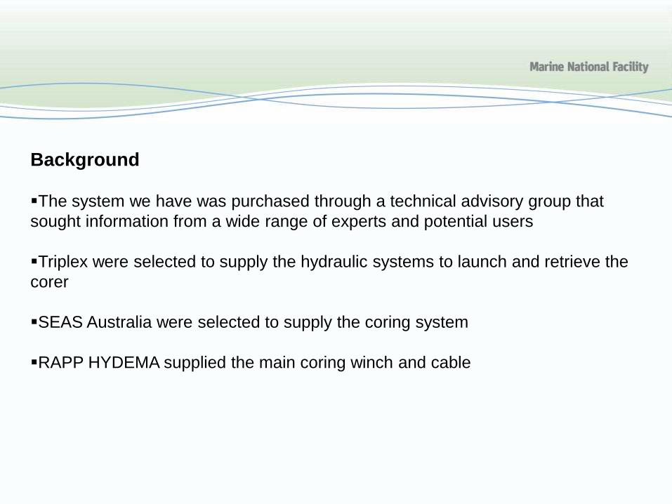
Brass
Shear strength 234 Mpa*
Diameter (mm) 2 3 4
Strength, double shear 1,470.27 3,308.10 5,881.06
Strength, double shear (kgf) 149.93 337.33 599.70
Spring Steel
Shear strength 1380 Mpa*
Diameter (mm) 2 3 4
Strength, double shear 8,670.80 19,509.29 34,683.18
Strength, double shear (kgf) 884.18 1,989.40 3,536.71

Core
length
Number of
3m
Number of
weights
Piston
Corer
Weight
required Total Trigger Number of
TOTAL
System
core barrelson Piston
Corer
Total
Weight
(F1) to
Balanceweight
Weights
Required Weight
n1 n2 F2 F2 * d2 / d1 F1 t1
(m) (kg) (kg) (kg) (kg) (30kg each) (kg)
W
12 4 0 420.0 21.0 40.0 0 460.0
1 680.0 34.0 70.0 1 750.0
2 940.0 47.0 70.0 1 1,010.0
3 1,200.0 60.0 100.0 2 1,300.0
4 1,460.0 73.0 100.0 2 1,560.0
5 1,720.0 86.0 130.0 3 1,850.0
6 1,980.0 99.0 130.0 3 2,110.0
7 2,240.0 112.0 160.0 4 2,400.0
8 2,500.0 125.0 160.0 4 2,660.0

• The system in piston mode
showing the trigger mechanism
clamping onto the piston cable and
the head weight
• The pilot core hangs off the trigger
arm
• The amount of freefall is
determined by the loop of piston
cable between the clamp and the
core head

Trigger mechanism
Trigger or Pilot core

Piston core release arm

Barrel gripper supplied with the Triplex system

New barrel gripperIt is lighter and slides up and down the pipe a lot easier

The Core being deployed in
gravity mode with 6m of barrel
Core is rotated, lifted out of the LARS
then deployed down to 100m above the
sea floor
After stabilising at 100m up we lowered
the core into the seafloor at 60 m per
minute
On later voyages we slowed this to
30m per minute as we had suffered pipe
breakage after some faster deployments
Free fall and recoil
We have decided to use 3m of free fall
Cable recoil was initially discounted as we are using a low stretch
polyamide rope Kapaneema dyneema SK-75 (MBL 52.05 t)
After contacting the manufacturer I obtained some basic data on expected
stretch with load and calculated the formulae:
%S=0.0006(core wt t)^2+0.0817(Core wt t)-0.1841
Elongation at failure was stated as 5%
On the deployment to 3,100m of water we allowed 3m of freefall and 3m
of recoil (calculated at 0.03% but we used 1% stretch) so the piston cable
loop was 6m long

Gravity mode
• Our best result so far is 10.2m of core out of 12m of barrel with a 2.21
tonne head weight lowering @ 30m per minute into the seafloor
Piston mode
This system uses a 2 part piston with facilities for 2, 3 or 4mm shear pins
At this stage we are still testing different sizes and materials for the shear
pins
Best result was using a 2mm brass and a 3mm spring steel pin
(2,139kg) with 15m of barrel and 2.21 tonnes of weight
13.62m of core was returned with piston still at the water sediment
interface from 3,100m of water and 15m of barrel

Conclusions
The system is relatively new to my team and we have had some good
results, interspersed with some interesting ones
Some results have been disappointing i.e. when the fingers in the cutter had
reversed and the sample been lost
We have since increased the strength of the fingers and had good results in
a mixed clay/sandy substrate
On another occasion the cam jaws were still open and no sample had been
retained
Upon inspection of the jaws were found to have tried to close but
damage in the centre indicated that a rock had held them open causing
the closing levers to bend and distort the pivot screws

Feedback please
Penetration speed into the sea floor
The amount of recoil in polyamide ropes
The strength of shear pin to use in 100mm diameter core pipe and if this
should vary for different sediments
Barrel gripper design
Types of steel used in the retaining fingers of the core catcher
Internal diameter of the core cutter compared to the internal diameter of
the core liner

Future research vessel projectFor further information:Mark LewisCSIRO, O&A Hobart.Email: [email protected]
Thank you for your attention
Questions?