Embed Size (px)
Citation preview
PAGE 1 CES WIRELESS TECHNOLOGIES CORP 2009
RV Series Application and Information Bulletin
CONFIDENTIAL RESELLER INFORMATION
The information in this manual and any software in this product remain the property of CES Wireless. Duplication or disclosure is not permitted without the prior written consent of CES Wireless. CES Wireless
reserves the right to change products, specifications, and installation data at any time, without notice.
All information contained in this document is carefully prepared and offered in good faith as a guide in the installation, operation, use and servicing of our products. Installers must insure that the final installation operates
satisfactory, within relevant regulatory requirements. We accept no responsibility for incorrect installations.
All CES products are sold subject to CES Terms and Conditions of Sale - No Exceptions.
A CES Wireless PUBLICATION 2009
PAGE 2 CES WIRELESS TECHNOLOGIES CORP 2009
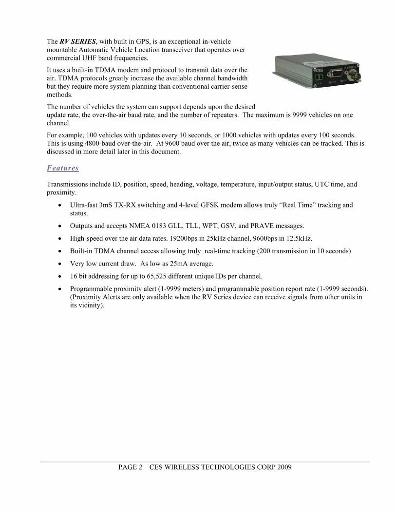
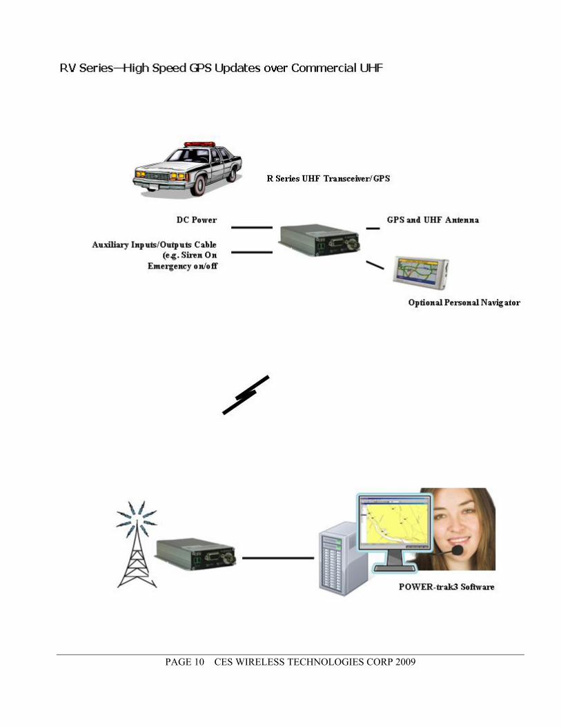
The RV SERIES, with built in GPS, is an exceptional in-vehicle mountable Automatic Vehicle Location transceiver that operates over commercial UHF band frequencies.
It uses a built-in TDMA modem and protocol to transmit data over the air. TDMA protocols greatly increase the available channel bandwidth but they require more system planning than conventional carrier-sense methods.
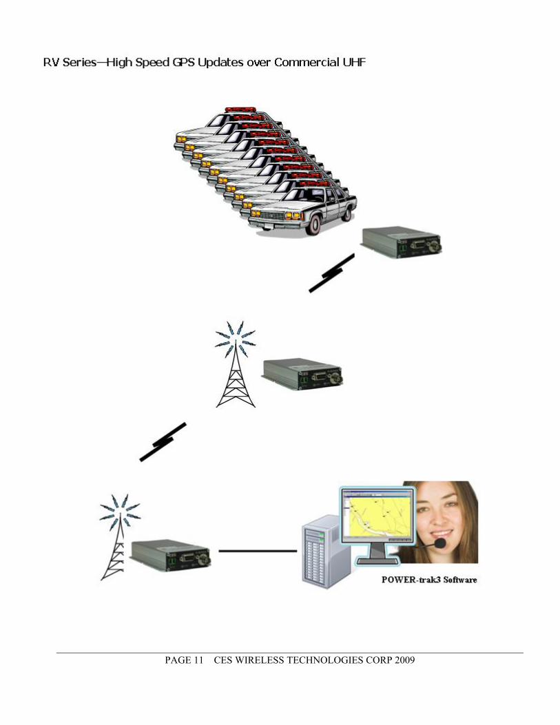
The number of vehicles the system can support depends upon the desired update rate, the over-the-air baud rate, and the number of repeaters. The maximum is 9999 vehicles on one channel.
For example, 100 vehicles with updates every 10 seconds, or 1000 vehicles with updates every 100 seconds. This is using 4800-baud over-the-air. At 9600 baud over the air, twice as many vehicles can be tracked. This is discussed in more detail later in this document.
Features
Transmissions include ID, position, speed, heading, voltage, temperature, input/output status, UTC time, and proximity.
• Ultra-fast 3mS TX-RX switching and 4-level GFSK modem allows truly “Real Time” tracking and status.
• Outputs and accepts NMEA 0183 GLL, TLL, WPT, GSV, and PRAVE messages.
• High-speed over the air data rates. 19200bps in 25kHz channel, 9600bps in 12.5kHz.
• Built-in TDMA channel access allowing truly real-time tracking (200 transmission in 10 seconds)
• Very low current draw. As low as 25mA average.
• 16 bit addressing for up to 65,525 different unique IDs per channel.
• Programmable proximity alert (1-9999 meters) and programmable position report rate (1-9999 seconds). (Proximity Alerts are only available when the RV Series device can receive signals from other units in its vicinity).
PAGE 3 CES WIRELESS TECHNOLOGIES CORP 2009
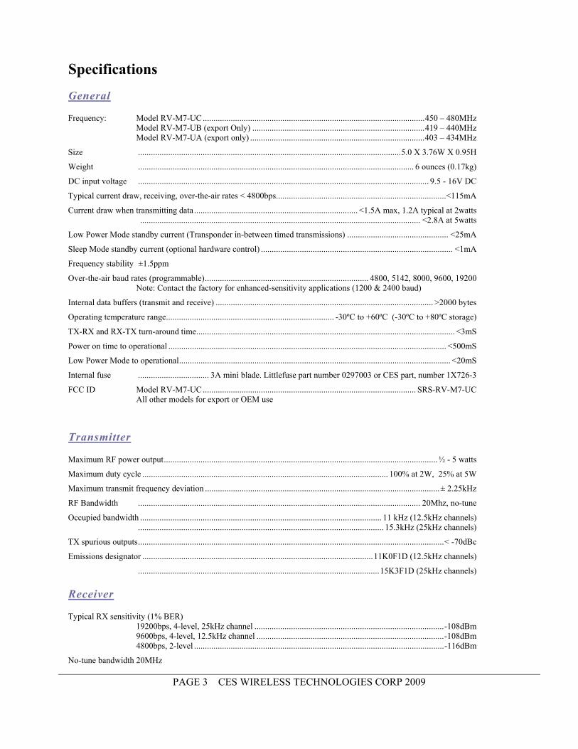
Specifications
General
Frequency: Model RV-M7-UC.......................................................................................................450 – 480MHz Model RV-M7-UB (export Only) ................................................................................419 – 440MHz Model RV-M7-UA (export only) .................................................................................403 – 434MHz
Size ..........................................................................................................................5.0 X 3.76W X 0.95H
Weight ................................................................................................................................ 6 ounces (0.17kg)
DC input voltage ....................................................................................................................................... 9.5 - 16V DC
Typical current draw, receiving, over-the-air rates < 4800bps...............................................................................<115mA
Current draw when transmitting data............................................................................ <1.5A max, 1.2A typical at 2watts .................................................................................................................................. <2.8A at 5watts
Low Power Mode standby current (Transponder in-between timed transmissions) ............................................... <25mA
Sleep Mode standby current (optional hardware control) ......................................................................................... <1mA
Frequency stability ±1.5ppm
Over-the-air baud rates (programmable)............................................................................ 4800, 5142, 8000, 9600, 19200 Note: Contact the factory for enhanced-sensitivity applications (1200 & 2400 baud)
Internal data buffers (transmit and receive) ..................................................................................................... >2000 bytes
Operating temperature range.............................................................................. -30ºC to +60ºC (-30ºC to +80ºC storage)
TX-RX and RX-TX turn-around time........................................................................................................................ <3mS
Power on time to operational ................................................................................................................................. <500mS
Low Power Mode to operational.............................................................................................................................. <20mS
Internal fuse ................................. 3A mini blade. Littlefuse part number 0297003 or CES part, number 1X726-3
FCC ID Model RV-M7-UC................................................................................................... SRS-RV-M7-UC All other models for export or OEM use
Transmitter
Maximum RF power output............................................................................................................................... ½ - 5 watts
Maximum duty cycle .................................................................................................................. 100% at 2W, 25% at 5W
Maximum transmit frequency deviation .............................................................................................................± 2.25kHz
RF Bandwidth ................................................................................................................................... 20Mhz, no-tune
Occupied bandwidth ................................................................................................................ 11 kHz (12.5kHz channels) .................................................................................................................. 15.3kHz (25kHz channels)
TX spurious outputs..............................................................................................................................................< -70dBc
Emissions designator ...........................................................................................................11K0F1D (12.5kHz channels)
................................................................................................................15K3F1D (25kHz channels)
Receiver
Typical RX sensitivity (1% BER) 19200bps, 4-level, 25kHz channel ........................................................................................-108dBm 9600bps, 4-level, 12.5kHz channel .......................................................................................-108dBm 4800bps, 2-level ....................................................................................................................-116dBm
No-tune bandwidth 20MHz
PAGE 4 CES WIRELESS TECHNOLOGIES CORP 2009
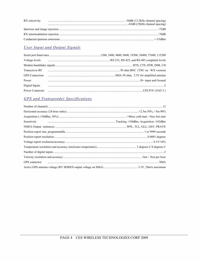
RX selectivity ....................................................................................................... -50dB (12.5kHz channel spacing) .......................................................................................................... -65dB (25kHz channel spacing)
Spurious and image rejection.....................................................................................................................................-75dB
RX intermodulation rejection ....................................................................................................................................-70dB
Conducted spurious emissions ............................................................................................................................. <-53dBm
User Input and Output Signals
Serial port baud rates ....................................................................1200, 2400, 4800, 9600, 19200, 38400, 57600, 115200
Voltage levels ...................................................................................RS-232, RS-422, and RS-485 complaint levels
Modem handshake signals ....................................................................................................... RTS, CTS, DTR, DSR, CD
Transceiver RF ................................................................................................50 ohm BNC (TNC on –WX version)
GPS Connection ......................................................................................... SMA 50 ohm, 3.3V for amplified antenna
Power ...........................................................................................................................B+ input and Ground
Digital Inputs ...........................................................................................................................................................2
Power Connector .............................................................................................................................. CES P/N 1J165-3 )
GPS and Transponder Specifications
Number of channels .........................................................................................................................................................12
Horizontal accuracy (24 hour static) ................................................................................................<2.5m 50%, <5m 90%
Acquisition (-130dBm, 50%)...........................................................................................<40sec cold start, <8sec hot start
Sensitivity .......................................................................................... Tracking -150dBm, Acquisition -142dBm
NMEA Output sentences ................................................................................................WPL, TLL, GLL, GSV, PRAVE
Position report rate, programmable......................................................................................................... 1 to 9999 seconds
Position report resolution.............................................................................................................................0.0001 degrees
Voltage report resolution/accuracy ..................................................................................................................... 0.1V/10%
Temperature resolution and accuracy (enclosure temperature)..................................................... 2 degrees C/4 degrees C
Number of digital inputs ....................................................................................................................................................3
Velocity resolution and accuracy......................................................................................................... 1km / 1km per hour
GPS connector .................................................................................................................................................... SMA
Active GPS antenna voltage (RV SERIES output voltage on SMA).............................................. 3.3V, 20mA maximum
PAGE 5 CES WIRELESS TECHNOLOGIES CORP 2009
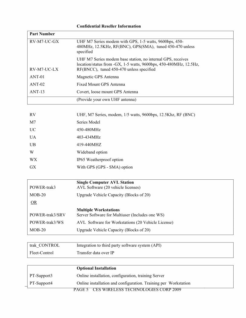
Confidential Reseller Information
Part Number
RV-M7-UC-GX
UHF M7 Series modem with GPS, 1-5 watts, 9600bps, 450-480MHz, 12.5KHz, RF(BNC), GPS(SMA), tuned 450-470 unless specified
RV-M7-UC-LX
UHF M7 Series modem base station, no internal GPS, receives location/status from -GX, 1-5 watts, 9600bps, 450-480MHz, 12.5Hz, RF(BNCC), tuned 450-470 unless specified
ANT-01 Magnetic GPS Antenna
ANT-02 Fixed Mount GPS Antenna
ANT-13 Covert, loose mount GPS Antenna
(Provide your own UHF antenna)
RV UHF, M7 Series, modem, 1/5 watts, 9600bps, 12.5Khz, RF (BNC)
M7 Series Model
UC 450-480MHz
UA 403-434MHz
UB 419-440MHZ
W Wideband option
WX IP65 Weatherproof option
GX With GPS (GPS - SMA) option
POWER-trak3 Single Computer AVL Station AVL Software (20 vehicle licenses)
MOB-20 Upgrade Vehicle Capacity (Blocks of 20)
OR
POWER-trak3/SRV Multiple Workstations Server Software for Multiuser (Includes one WS)
POWER-trak3/WS AVL Software for Workstations (20 Vehicle License)
MOB-20 Upgrade Vehicle Capacity (Blocks of 20)
trak_CONTROL Integration to third party software system (API)
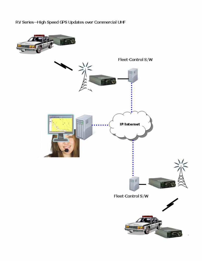
Fleet-Control Transfer data over IP
Optional Installation
PT-Support3 Online installation, configuration, training Server
PT-Support4 Online installation and configuration. Training per Workstation
PAGE 6 CES WIRELESS TECHNOLOGIES CORP 2009
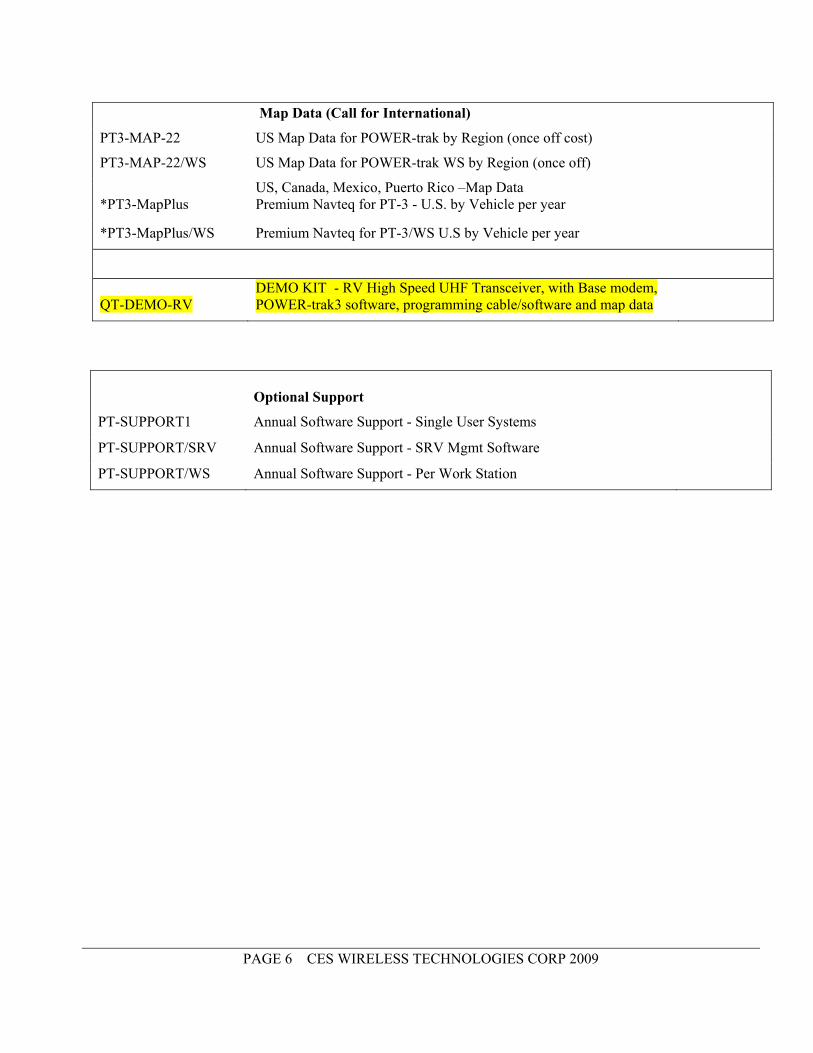
Map Data (Call for International)
PT3-MAP-22 US Map Data for POWER-trak by Region (once off cost)
PT3-MAP-22/WS US Map Data for POWER-trak WS by Region (once off)
*PT3-MapPlus US, Canada, Mexico, Puerto Rico –Map Data Premium Navteq for PT-3 - U.S. by Vehicle per year
*PT3-MapPlus/WS Premium Navteq for PT-3/WS U.S by Vehicle per year
QT-DEMO-RV DEMO KIT - RV High Speed UHF Transceiver, with Base modem, POWER-trak3 software, programming cable/software and map data
Optional Support
PT-SUPPORT1 Annual Software Support - Single User Systems
PT-SUPPORT/SRV Annual Software Support - SRV Mgmt Software
PT-SUPPORT/WS Annual Software Support - Per Work Station
PAGE 7 CES WIRELESS TECHNOLOGIES CORP 2009
Encryption
For privacy and security, over-the air encryption is standard on every RV SERIES radio. For network versatility, the RV SERIES incorporates a 16-bit identification code.
All RV SERIES transponders may be set to store-and-forward/messages (repeater for wide area coverage) from other RV SERIES transponders while sending their own GPS update.
Operation Modes
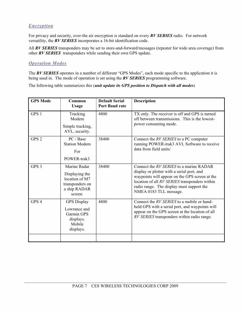
The RV SERIES operates in a number of different “GPS Modes”, each mode specific to the application it is being used in. The mode of operation is set using the RV SERIES programming software.
The following table summarizes this (unit update its GPS position to Dispatch with all modes)
GPS Mode Common Usage
Default Serial Port Baud rate
Description
GPS 1 Tracking Modem
Simple tracking, AVL, security.
4800 TX only. The receiver is off and GPS is turned off between transmissions. This is the lowest-power consuming mode.
GPS 2 PC / Base Station Modem
For
POWER-trak3.
38400 Connect the RV SERIES to a PC computer running POWER-trak3 AVL Software to receive data from field units/
GPS 3 Marine Radar
Displaying the location of M7 transponders on a ship RADAR
screen.
38400 Connect the RV SERIES to a marine RADAR display or plotter with a serial port, and waypoints will appear on the GPS screen at the location of all RV SERIES transponders within radio range. The display must support the NMEA 0183 TLL message.
GPS 4 GPS Display
Lowrance and Garmin GPS
displays. Mobile
displays.
4800 Connect the RV SERIES to a mobile or hand-held GPS with a serial port, and waypoints will appear on the GPS screen at the location of all RV SERIES transponders within radio range.
PAGE 8 CES WIRELESS TECHNOLOGIES CORP 2009
Electrical Inputs and Outputs The front panel of the RV SERIES modem has these features:
• RF connector
• Power LED
• Status LED (Receive data = green, TX = red)
• 9-Pin Serial I/O connector
• DC Power Jack
LEDs
The status LED visually show the current status of the radio.
• Status LED (TX) This LED blinks red when the transmitter keys and is putting out RF power. It blinks green upon the reception of data or RF carrier.
• Power LED (PWR) This LED does a short blink, once every two seconds, indicating to the user that the power to the modem is ON and the modem is working. When the modem is in the command mode, this LED will blink on and off, once per second.
When the GPS is trying to acquire satellite lock, the Status and Power LEDs will alternately blink back and forth. This usually takes 10-20 seconds upon power-up or loss of satellite signal.
DC Power
DC power for the modem is connected to the 2-pin DC power input jack labeled DC IN. Use the supplied cable to connect the DC power. The red wire is positive (+) and the black wire is negative (-). Its connection is optional, as the user may alternately apply power to Pin 9 and ground to pin 5 of the 9-pin I/O connector. If the power cable run is over 3 feet long, CES recommends at least 18 AWG wire be used.
The RV SERIES is supplied with a 6-foot DC power cable, CES part number 1C738-1.
Note: The RV SERIES has in internal 3-amp mini-fuse (automotive type) to protect it and its power source against reverse voltage and serious hardware failures.
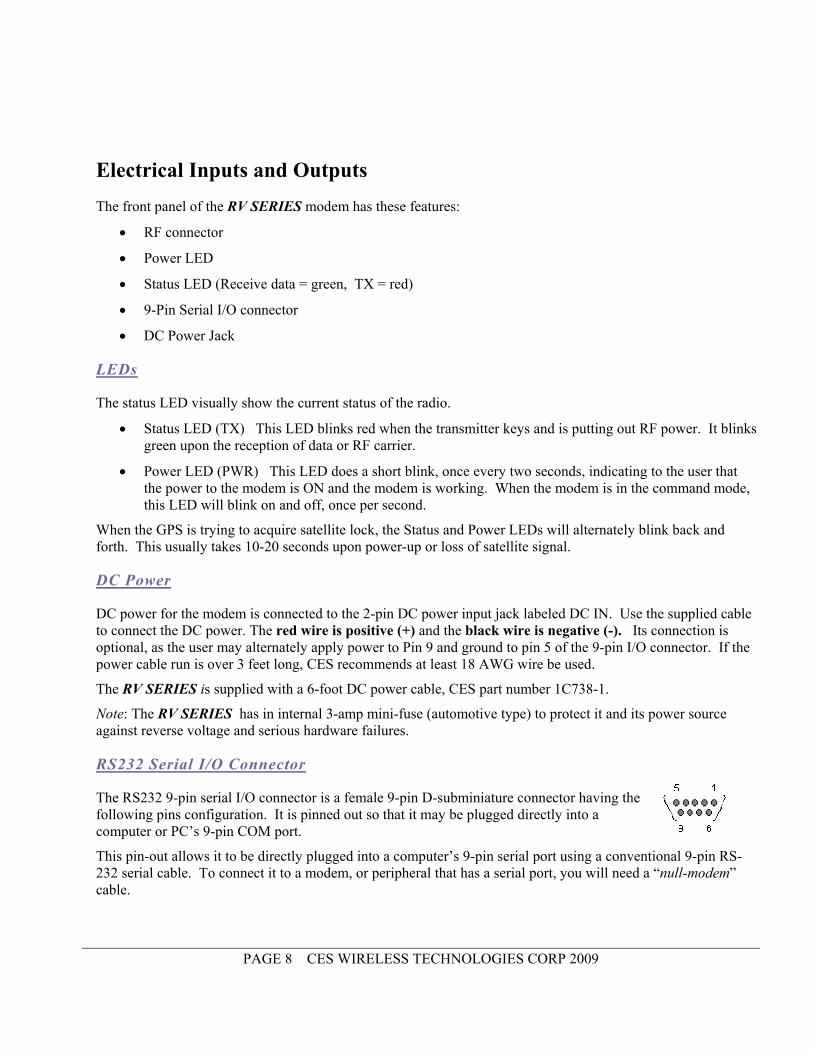
RS232 Serial I/O Connector
The RS232 9-pin serial I/O connector is a female 9-pin D-subminiature connector having the following pins configuration. It is pinned out so that it may be plugged directly into a computer or PC’s 9-pin COM port.
This pin-out allows it to be directly plugged into a computer’s 9-pin serial port using a conventional 9-pin RS-232 serial cable. To connect it to a modem, or peripheral that has a serial port, you will need a “null-modem” cable.
PAGE 9 CES WIRELESS TECHNOLOGIES CORP 2009
Time Slots
For optimum efficiency in a RV SERIES system, begin sequentially numbering at ID 0001. The second unit should be ID 0002, and so on.
The RV SERIES can measure time and initiate transmissions 20 times every second (every 50mS). By default the TDMA time slot is 200mS long, and thus in 10 seconds, up to 50 units may report position. These parameters are programmable, and may be re-configured based upon the type of system they are used in.
Security Key
The security KEY programmed into every RV SERIES transponder ensures that only RV SERIES transponders with the exact same security code can receive position and status information. The default is CESWIRELESS.
When you program your own security code into your RV SERIES transponders, write it down in a secure place. This parameter cannot be read out of the M7 GX.
Addressing Basics
Each RV SERIES has an ID programmed into it, and is represented as a 4 digit number. RV SERIES IDs may be any number between 0001 and 9999.
PAGE 10 CES WIRELESS TECHNOLOGIES CORP 2009
PAGE 11 CES WIRELESS TECHNOLOGIES CORP 2009
PAGE 12 CES WIRELESS TECHNOLOGIES CORP 2009
PAGE 13 CES WIRELESS TECHNOLOGIES CORP 2009
FAQ
Is the unit FCC approved?
Yes
Is the unit approved for use in Canada? No. Not yet, but it is FCC approved
Does it have any out of coverage memory? No
Are updates acknowledged? No Can units act as Store and Forward and update their locations? Yes
Can I use a regular Repeater with the RV SERIES No. You must use the RV SERIES programmed to act as Store and Forward.
Does the system provide Acknowledgement
No. Because of the rapid updates, an ACK is not necessary.
What base software can I use? The RV Series is designed to operate with CES POWER-trak3 AVL Tracking and Fleet management Software. It is not yet with CES FleetLinc web based tracking software.
Does the solution integrate to non-CES Software Systems? POWER-trak3 interfaces with most of the popular vertical market software packages on the market (911, Public Safety, Water Authorities, School Authorities, Readymix etc)
How many channels has the RV Series The unit has 12 channels, but only one is active at a time.
How far will a 5-watt UHF radio communicate?
An excellent question, but very difficult to answer. It depends on the following (in order of importance):
The height of the antennas above the average terrain.
The terrain itself - vegetation and buildings.
The over-the-air data rate. For example, 4800 baud works much further than 9600 baud.
There are only two good methods to determine range. Either create an accurate computer model of the system and the terrain, or drive the area and test the coverage. Since these can be impractical at times, here are some “rules of thumb” for 4800-baud communications range. 9600-baud range is approximately ½ of these.
In flat wide-open areas, such as deserts, grasslands, and farms, vehicle-to-vehicle communications will be 2 miles on the low end and often as much as 10 miles on the high end. A base-station, either with a 15-meter tower or placed on a local hill, will reliably communicate out to 10 miles, and often out to 20-30 miles.
PAGE 14 CES WIRELESS TECHNOLOGIES CORP 2009
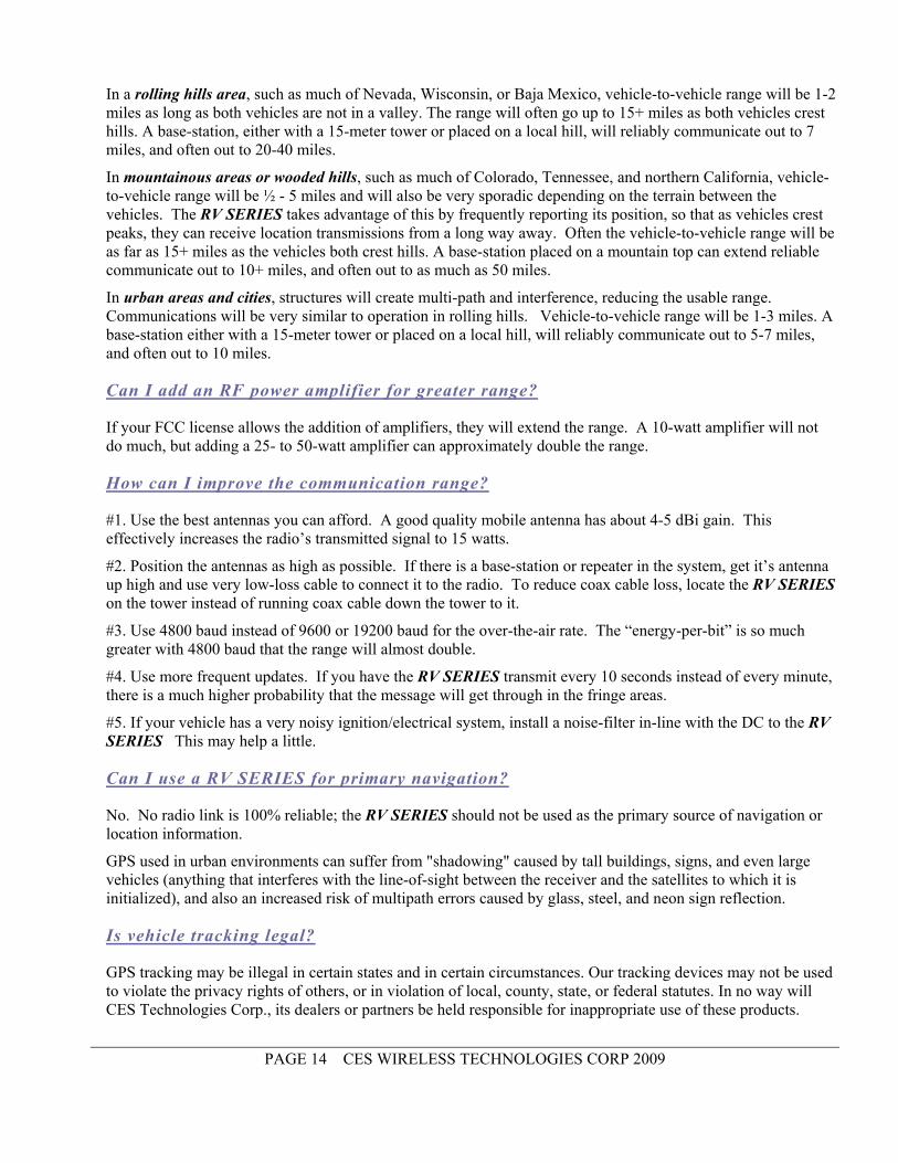
In a rolling hills area, such as much of Nevada, Wisconsin, or Baja Mexico, vehicle-to-vehicle range will be 1-2 miles as long as both vehicles are not in a valley. The range will often go up to 15+ miles as both vehicles crest hills. A base-station, either with a 15-meter tower or placed on a local hill, will reliably communicate out to 7 miles, and often out to 20-40 miles.
In mountainous areas or wooded hills, such as much of Colorado, Tennessee, and northern California, vehicle-to-vehicle range will be ½ - 5 miles and will also be very sporadic depending on the terrain between the vehicles. The RV SERIES takes advantage of this by frequently reporting its position, so that as vehicles crest peaks, they can receive location transmissions from a long way away. Often the vehicle-to-vehicle range will be as far as 15+ miles as the vehicles both crest hills. A base-station placed on a mountain top can extend reliable communicate out to 10+ miles, and often out to as much as 50 miles.
In urban areas and cities, structures will create multi-path and interference, reducing the usable range. Communications will be very similar to operation in rolling hills. Vehicle-to-vehicle range will be 1-3 miles. A base-station either with a 15-meter tower or placed on a local hill, will reliably communicate out to 5-7 miles, and often out to 10 miles.
Can I add an RF power amplifier for greater range?
If your FCC license allows the addition of amplifiers, they will extend the range. A 10-watt amplifier will not do much, but adding a 25- to 50-watt amplifier can approximately double the range.
How can I improve the communication range?
#1. Use the best antennas you can afford. A good quality mobile antenna has about 4-5 dBi gain. This effectively increases the radio’s transmitted signal to 15 watts.
#2. Position the antennas as high as possible. If there is a base-station or repeater in the system, get it’s antenna up high and use very low-loss cable to connect it to the radio. To reduce coax cable loss, locate the RV SERIES on the tower instead of running coax cable down the tower to it.
#3. Use 4800 baud instead of 9600 or 19200 baud for the over-the-air rate. The “energy-per-bit” is so much greater with 4800 baud that the range will almost double.
#4. Use more frequent updates. If you have the RV SERIES transmit every 10 seconds instead of every minute, there is a much higher probability that the message will get through in the fringe areas.
#5. If your vehicle has a very noisy ignition/electrical system, install a noise-filter in-line with the DC to the RV SERIES This may help a little.
Can I use a RV SERIES for primary navigation?
No. No radio link is 100% reliable; the RV SERIES should not be used as the primary source of navigation or location information.
GPS used in urban environments can suffer from "shadowing" caused by tall buildings, signs, and even large vehicles (anything that interferes with the line-of-sight between the receiver and the satellites to which it is initialized), and also an increased risk of multipath errors caused by glass, steel, and neon sign reflection.
Is vehicle tracking legal?
GPS tracking may be illegal in certain states and in certain circumstances. Our tracking devices may not be used to violate the privacy rights of others, or in violation of local, county, state, or federal statutes. In no way will CES Technologies Corp., its dealers or partners be held responsible for inappropriate use of these products.
PAGE 15 CES WIRELESS TECHNOLOGIES CORP 2009
IT IS THE SOLE RESPONSIBILITY OF THE BUYER TO CONSULT LEGAL COUNSEL FOR THE INTERPRETATION OF ANY LAWS APPLICABLE TO THE AREA OF INTENDED USE OF THESE PRODUCTS.
What is NMEA?
National Marine Electronics Association (NMEA) 0183 is a combined electrical and data specification for communication between marine electronic devices, such as echo sounders, sonar’s, anemometers (wind speed and direction), gyrocompasses, autopilots, GPS receivers, and many other types of instruments. It has been defined by, and is controlled by, the US-based National Marine Electronics Association. Although it is a marine-electronics protocol, it is widely used in hand-held and mobile GPS displays and navigation systems.
The NMEA 0183 standard uses an ASCII serial communications protocol that defines how data is transmitted in a "sentence" from one "talker" to one "listener" at a time. Communications is typically at 4800 baud for GPS devices. Through the use of intermediate expanders, a “talker” can have a unidirectional conversation with multiple “listeners.” Using multiplexers, multiple sensors can talk to a single computer port. Third-party switches are available that can establish a primary and secondary “talker,” with automatic failover if the primary fails.
Many GPS receivers have NMEA compatible serial ports on them. The Lowrance 540C and the Garmin 60C are two examples. The RV SERIES speaks the NMEA protocol to these GPS’s in order to display numbered icons on their screens at the location it receives from other GPS’s.
What Map Datum is used in the RV Series?
All latitude and longitudes are reported using World Geodetic Survey 1984 (WGS85) datum. Speed is reported in km/hour. Time is UTC as reported by the GPS receiver. Altitude is in meters.
How many vehicles can the System support?
The number of vehicle the system can support depends upon the desired update rate, the over-the-air baud rate, and the number of repeaters. The maximum is 9999 vehicles on one channel.
The simple answer is: 100 vehicles with updates every 10 seconds or 1000 vehicles with updates every 100 seconds. This is using 4800-baud over-the-air. At 9600 baud over the air, twice as many vehicles can be tracked.
The ID structure in the RV SERIES modem is 16-bits, allowing for over 65,000 unique IDs, and therefore 65,000 uniquely identified radios. But there are other practical limits to consider in a large system. How often are updates needed? How many RF channels will be used? How many repeaters will be used?
In real-time tracking, each RV SERIES uses some multiple of 50mS time slots to report their positions. For 4800 baud, the RV SERIES needs two slots. If run at 9600 baud, it only needs one slot to report position and status. A typical RV SERIES at 4800-baud over-the-air rate uses 100mS to report its position.
If a repeater is used in the system, then it needs another 100mS to repeat the message, so the number of 50mS time-slots allocated to each unit would be four (200mS total). This number is programmable in the RV SERIES;; the factory default is 200mS.
Therefore, in one second, five RV SERIES transponders could report, and have their messages repeated once.
In one minute, 300 transponders could report in. In 5 minutes, 1500. In one hour, 18,000. But only if each one reported once during that interval.
The formula for the number of possible RV SERIES transponders in use at one time is:
N = S X R X U (seconds)
PAGE 16 CES WIRELESS TECHNOLOGIES CORP 2009
S = Slot time programmed into the RV SERIES (0.10 for 4800 baud 0.005 for 9600 baud)
R = Number of repeaters that must sequentially repeat the transmission (Typical systems will have one repeater.)
U = Update Rate (This is the number of seconds between position reports.)
For systems up to about 300-500 units, this TDMA approach is very efficient. If 1000’s of devices must be tracked, and there is only one RF channel available, the Update Rate in the RV SERIES can be set to a small number, such as 10 seconds, but the report-by-exception features should be used. These stop the RV SERIES from transmitting its data unless an exception occurs (input change, speeding, proximity alert, etc.). When exception reporting is used, the RF channel is not used unless an exception occurs. Typically the user will program the RV SERIES to report once-per-hour or once-per-day even if an exception does not occur.
What is the accuracy of the RV Series GPS position report?
GPS accuracy is very hard to predict. The GPS receiver in the RV SERIES has these specifications:
Horizontal <3 meters (50%), <8 meters (90%)
Altitude <10 meters (50%), <16 meters (90%)
Velocity 0.06 m/sec
Tests show that the unit-to-unit position difference when two RV SERIES are very near each other is typically within +/- 0.00001 degrees (1.6meters).
Why not send positions to the GPS satellite?
Unlike other satellite systems, such as Global Star or Iridium, GPS satellites cannot receive data. They only transmit position information for use by GPS receivers. This is a one-way system.
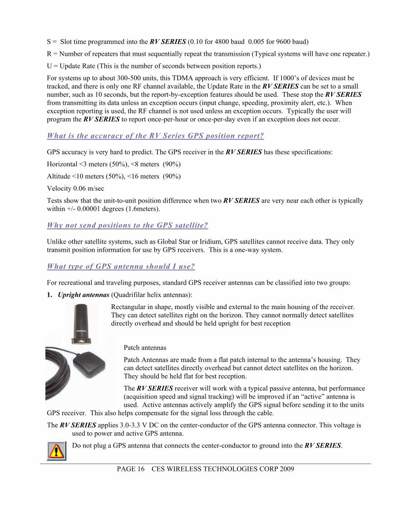
What type of GPS antenna should I use?
For recreational and traveling purposes, standard GPS receiver antennas can be classified into two groups:
1. Upright antennas (Quadrifilar helix antennas):
Rectangular in shape, mostly visible and external to the main housing of the receiver. They can detect satellites right on the horizon. They cannot normally detect satellites directly overhead and should be held upright for best reception
Patch antennas
Patch Antennas are made from a flat patch internal to the antenna’s housing. They can detect satellites directly overhead but cannot detect satellites on the horizon. They should be held flat for best reception.
The RV SERIES receiver will work with a typical passive antenna, but performance (acquisition speed and signal tracking) will be improved if an “active” antenna is used. Active antennas actively amplify the GPS signal before sending it to the units
GPS receiver. This also helps compensate for the signal loss through the cable.
The RV SERIES applies 3.0-3.3 V DC on the center-conductor of the GPS antenna connector. This voltage is used to power and active GPS antenna.
Do not plug a GPS antenna that connects the center-conductor to ground into the RV SERIES.
PAGE 17 CES WIRELESS TECHNOLOGIES CORP 2009
Sample of Market Specific Software Partners
Taxi Dispatch/Trans portation Soft-ware The CES Wireless TRK-240 and POW ER-trak3 provides capability with SmartDispatch Products
SmartDispatch Corporation 42 Arbusto
Irvine, CA 92606 Ph. 949.653.8900
www.s martdispatch.com
Utility Software POW ER-trak3 is plug and play compati-ble with Ut ility specific software avail-able from Milsoft.
Milsoft 4400 Buffalo Gap Road
Abilene, TX 79606 325.695.1642
www.milsoft.com
School Trans portation POW ER-trak3 is plug and play compati-ble with school transportation specific software available from Edulog.
Education Logistics, Inc
3000 Palmer Street Missoula, MT 59808
(406) 728-0893 www.edulog.com
Public Safety/911/Fire/Medical/Police Dispatch POW ER-trak3 is plug and play compati-ble with Public Safety specific software available from Interact.
Interact911 102 W. 3rd Street Winston-Salem, NC 27101 USA
www.interact911.com
ReadyMix/Aggregrate/Construction POW ER-trak3 is plug and play compati-ble with Systech software.
Systech Inc. 9014 Heritage Parkway,
Woodridge, IL 60517-4939 www.systech-inc.com
ReadyMix/Aggregrate/Construction POW ER-trak3 is plug and play compati-ble with CommandAlkon software.
CommandAlkon 1800 International Park Dr.
Birmingham, Al 35243 Tel: (205) 879-3282
www.commandalkon.com
Emergency Services, Law enforcement Fire Ambulance service POW ER-trak3 is plug and play compati-ble with Geac software.
GEAC EnRoute Emergency Systems
401 East Jackson Street, Tampa, FL, 33602-5204
Fire and EMS POW ER-trak3 is plug and play compati-ble with Zoll Data software.
Zoll Data Systems Pinpoint Technologies
12202 Airport Way, Broomfield, CO 80021 U..A.
303.801.0000