Embed Size (px)
Citation preview

IMPORTANT!Please record the serial number of thisunit in the space below.
Model:Serial No.:
The serial number is located on the rearof the unit.Retain this Owner’s Manual in a safeplace for future reference.
WARNINGTO REDUCE THE RISK OF FIRE ORELECTRIC SHOCK, DO NOT EXPOSETHIS UNIT TO RAIN OR MOISTURE.
RISK OF ELECTRIC SHOCKDO NOT OPEN
CAUTION: TO REDUCE THE RISK OFELECTRIC SHOCK, DO NOT REMOVE
COVER (OR BACK), NO USER-SERVICEABLEPARTS INSIDE, REFER SERVICING TO
QUALIFIED SERVICE PERSONNEL.
The lightning flash with arrowheadsymbol, within an equilateral triangle,is intended to alert you to thepresence of uninsulated “dangerousvoltage” within the product’senclosure that may be of sufficientmagnitude to constitute a risk ofelectric shock to persons.
The exclamation point within anequilateral triangle is intended to alertyou to the presence of importantoperating and maintenance(servicing) instructions in theliterature accompanying theappliance.
• Explanation of Graphical Symbols
CAUTION
Natural Sound Stereo Receiver
Thank you for selecting this YAMAHA stereo receiver.
OWNER’S MANUAL
CONTENTS
Safety Instructions ................... 2Features ................................... 4Supplied Accessories .............. 4Profile of This Unit ................... 5Speaker Setup for This Unit ..... 6Connections ............................. 7Adjustment Before Operation ... 12Operations ............................. 15Tuning Operations .................. 17Using Digital Sound Field Processor (DSP) .................... 19Setting the SLEEP Timer ....... 24Remote Control Transmitter ... 25Notes about the Remote Control Transmitter ................. 28Troubleshooting ...................... 29Specifications ......................... 30
RX-V1070/870

1 Read Instructions – All the safety and operatinginstructions should be read before the unit is operated.
2 Retain Instructions – The safety and operating instructionsshould be retained for future reference.
3 Heed Warnings – All warnings on the unit and in theoperating instructions should be adhered to.
4 Follow Instructions – All operating and other instructionsshould be followed.
5 Water and Moisture – The unit should not be used nearwater – for example, near a bathtub, washbowl, kitchensink, laundry tub, in a wet basement, or near a swimmingpool, etc.
6 Carts and Stands – The unit should be used only with acart or stand that is recommended by the manufacturer.
6A A unit and cart combination shouldbe moved with care. Quick stops,excessive force, and unevensurfaces may cause the unit and cart combination to overturn.
7 Wall or Ceiling Mounting – The unitshould be mounted to a wall or ceiling only asrecommended by the manufacturer.
8 Ventilation – The unit should be situated so that itslocation or position does not interfere with its properventilation. For example, the unit should not be situatedon a bed, sofa, rug, or similar surface, that may block theventilation openings; or placed in a built-in installation,such as a bookcase or cabinet that may impede the flowof air through the ventilation openings.
9 Heat – The unit should be situated away from heatsources such as radiators, stoves, or other appliances thatproduce heat.
10 Power Sources – The unit should be connected to a powersupply only of the type described in the operatinginstructions or as marked on the unit.
11 Power-Cord Protection – Power-supply cords should berouted so that they are not likely to be walked on orpinched by items placed upon or against them, payingparticular attention to cords at plugs, conveniencereceptacles, and the point where they exit from the unit.
12 Cleaning – The unit should be cleaned only asrecommended by the manufacturer.
13 Nonuse Periods – The power cord of the unit should beunplugged from the outlet when left unused for a longperiod of time.
14 Object and Liquid Entry – Care should be taken so thatobjects do not fall into and liquids are not spilled into theinside of the unit.
15 Damage Requiring Service – The unit should be servicedby qualified service personnel when:
A. The power-supply cord or the plug has been damaged;or
B. Objects have fallen, or liquid has been spilled into the unit;or
C. The unit has been exposed to rain; or
D. The unit does not appear to operate normally or exhibits amarked change in performance; or
E. The unit has been dropped, or the cabinet damaged.
16 Servicing – The user should not attempt to service the unitbeyond those means described in the operatinginstructions. All other servicing should be referred toqualified service personnel.
17 Power Lines – An outdoor antenna should be locatedaway from power lines.
18 Grounding or Polarization – Precautions should be takenso that the grounding or polarization is not defeated.
19 Outdoor Antenna Grounding – If an outside antenna isconnected to this unit, be sure the antenna system isgrounded so as to provide some protection against voltagesurges and built-up static charges. Article 810 of theNational Electrical Code, ANSI/NFPA 70, providesinformation with regard to proper grounding of the mastand supporting structure, grounding of the lead-in wire toan antenna discharge unit, size of grounding conductors,location of antenna discharge unit, connection togrounding electrodes, and requirements for the groundingelectrode.
2
SAFETY INSTRUCTIONS
Note to CATV system installer:This reminder is provided to call the CATV systeminstaller's attention to Article 820-40 of the NEC thatprovides guidelines for proper grounding and, in particular, specifies that the cable ground shall beconnected to the grounding system of the building, asclose to the point of cable entry as practical.
EXAMPLE OF ANTENNA GROUNDING
MAST
GROUNDCLAMP
ANTENNALEAD INWIRE
ANTENNADISCHARGE UNIT(NEC SECTION 810–20)
GROUNDING CONDUCTORS(NEC SECTION 810–21)
GROUND CLAMPS
POWER SERVICE GROUNDINGELECTRODE SYSTEM(NEC ART 250. PART H)
ELECTRICSERVICEEQUIPMENT
NEC – NATIONAL ELECTRICAL CODE

1. IMPORTANT NOTICE : DO NOT MODIFY THIS UNIT!This product, when installed as indicated in theinstructions contained in this manual, meets FCCrequirements. Modifications not expressly approved byYamaha may void your authority, granted by the FCC, touse the product.
2. IMPORTANT : When connecting this product toaccessories and/or another product use only high qualityshielded cables. Cable/s supplied with this productMUST be used. Follow all installation instructions.Failure to follow instructions could void your FCCauthorization to use this product in the USA.
3. NOTE : This product has been tested and found tocomply with the requirements listed in FCC Regulations,Part 15 for Class “B” digital devices. Compliance withthese requirements provides a reasonable level ofassurance that your use of this product in a residentialenvironment will not result in harmful interference withother electronic devices.This equipment generates/uses radio frequencies and, ifnot installed and used according to the instructionsfound in the users manual, may cause interferenceharmful to the operation of other electronic devices.
Compliance with FCC regulations does not guarantee thatinterference will not occur in all installations. If this productis found to be the source of interference, which can bedetermined by turning the unit “OFF” and “ON”, please tryto eliminate the problem by using one of the followingmeasures:
Relocate either this product or the device that is beingaffected by the interference.
Utilize power outlets that are on different branch (circuitbreaker or fuse) circuits or install AC line filter/s.
In the case of radio or TV interference, relocate/reorient theantenna. If the antenna lead-in is 300 ohm ribbon lead,change the lead-in to coaxial type cable.
If these corrective measures do not produce satisfactoryresults, please contact the local retailer authorized todistribute this type of product. If you can not locate theappropriate retailer, please contact Yamaha ElectronicsCorp., U.S.A. 6660 Orangethorpe Ave, Buena Park, CA90620.
The above statements apply ONLY to those productsdistributed by Yamaha Corporation of America or itssubsidiaries.
Caution: Read this before operating your unit
3
1 To ensure the finest performance, please read thismanual carefully. Keep it in a safe place for futurereference.
2 Install your unit in a cool, dry, clean place – away fromwindows, heat sources, and too much vibration, dust,moisture or cold. Avoid sources of hum (transformers,motors). To prevent fire or electrical shock, do notexpose to rain and water.
3 Do not operate the unit upside-down. It may overheat,possibly causing damage.
4 Never open the cabinet. If a foreign object drops intothe set, contact your dealer.
5 Do not use force on switches, knobs or cords. Whenmoving the set, first turn the unit off. Then gentlydisconnect the power plug and the cords connecting toother equipment. Never pull the cord itself.
6 Do not attempt to clean the unit with chemical solvents;this might damage the finish. Use a clean, dry cloth.
7 Always set the volume control to “– ∞” before startingthe audio source play: increase the volume gradually toan appropriate level after the play is started.
8 To prevent lightning damage, pull out the power cordand remove the antenna cable during an electricalstorm.
9 Be sure to read the “Troubleshooting” section oncommon operating errors before concluding that yourunit is faulty.
10 Do not connect audio equipment to the AC outlets onthe rear panel if that equipment requires more powerthan the outlets are rated to provide.
FCC INFORMATION
YAMAHA and the Electronic Industries Association’sConsumer Electronics Group want you to get the most out ofyour equipment by playing it at a safe level. One that lets thesound come through loud and clear without annoying blaring ordistortion – and, most importantly, withoutaffecting your sensitive hearing. Since hearingdamage from loud sounds is often undetectableuntil it is too late, YAMAHA and the ElectronicIndustries Association’s Consumer ElectronicsGroup recommend you to avoid prolongedexposure from excessive volume levels.
We Want You Listening For A Lifetime

4
SUPPLIED ACCESSORIESAfter unpacking, check that the following parts are contained.
Remote Control Transmitter
<RX-V1070> <RX-V870>
Batteries (size AA, R6, UM-3)
User Program Sheets
Indoor FM Antenna
AM Loop Antenna
5 Speaker Configuration
<RX-V1070>Front: 110W + 110W (8Ω)/135W + 135W (6Ω)
RMS Output Power, 0.015% THD, 20–20,000 Hz
Center: 110W (8Ω)/135W (6Ω) RMS Output Power, 0.015% THD, 20–20,000 Hz
Rear: 30W + 30W (8Ω)/40W + 40W (6Ω) RMS Output Power, 0.08% THD, 1,000 Hz
<RX-V870>Front: 80W + 80W (8Ω)/95W + 95W (6Ω) RMS
Output Power, 0.015% THD, 20–20,000 Hz
Center: 80W (8Ω)/95W (6Ω) RMS Output Power, 0.015% THD, 20–20,000 Hz
Rear: 25W + 25W (8Ω)/28W + 28W (6Ω) RMS Output Power, 0.08% THD, 1,000 Hz
Digital Sound Field Processor (Including DolbyPro Logic Surround Decoder)4 Programs for Audio Sources4 Programs for Audio/Video Sources
Automatic Input Balance Control for DolbySurround
Test Tone Generator for Easier Speaker OutputBalance Adjustment
3 Center Channel Modes(NORMAL/WIDE/PHANTOM)
40-Station Random Preset Tuning
Video Signal Input/Output Capability (Including SVideo Connections)
SLEEP Timer
On Screen Displays Which Is Helpful inControlling This Unit
Programmable Remote Control Transmitter
FEATURES
OPEN/CLOSE THE CONTROL DOOR <for RX-V1070 only>When it is not necessary to operate controls inside the control door, close the door.
To close the door To open the door

5
PROFILE OF THIS UNITYou are the proud owner of this Yamaha stereo receiver –an extremely sophisticated audio component. The Digital Sound FieldProcessor (DSP) built into this unit takes full advantage of Yamaha’s undisputed leadership in the field of digital audio processing tobring you a whole new world of listening experiences. Follow the instructions in this manual carefully when setting up your system,and this unit will sonically transform your room into a wide range of listening environments –movie theater, concert hall, and so on.In addition, you get incredible realism from Dolby-encoded video sources using the built-in Dolby Pro Logic Surround Decoder.Rather than tell you about the wonders of digital sound field processing, however, let’s get right down to the business of setting upthe system and trying out its many capabilities. Please read this operation manual carefully and store it in a safe place for laterreference.
Digital Sound Field Processing
What is it that makes live music so good? Today’s advancedsound reproduction technology lets you get extremely close tothe sound of a live performance, but chances are you’ll stillnotice something missing: the acoustic environment of the liveconcert hall. Extensive research into the exact nature of thesonic reflections that create the ambience of a large hall hasmade it possible for Yamaha engineers to bring you this samesound in your own listening room, so you’ll feel all the sound ofa live concert.
What’s more, our technicians, armed with sophisticatedmeasuring equipment, have even made it possible to capturethe acoustics of a variety of venues such as an actual concerthall, theater, etc. to allow you to accurately recreate one ofseveral actual live performance environments, all in your ownhome.
Dolby Pro Logic Surround
The Dolby Pro Logic Surround Decoder program lets youexperience the dramatic realism and impact of Dolby Surroundmovie theater sound in your own home. Dolby Pro Logic getsits name from its professional-grade steering logic circuitry,which provides greater effective channel separation for a muchhigher degree of realism than the “passive” Dolby Surroundcircuits found in today’s typical home audio/video equipment.Dolby Pro Logic Surround provides a true center channel, sothat there are four independent channels, unlike passive DolbySurround which has in effect only three channels: left, right,and rear. This center channel allows listeners seated in evenless-than-ideal positions to hear the dialog originating fromaction on the screen while getting a stereo effect as well.
This Dolby Pro Logic Surround Decoder employs a digitalsignal processing system. This system increases soundstability at each channel and minimizes crosstalk betweenchannels compared to conventional analog Dolby signalprocessing.In addition, this unit features a built-in automatic input balancecontrol. This circuit always presents you the best surroundconditions without performing manual adjustments.
Dolby Pro Logic Surround + DSP
You can also enjoy Dolby Pro Logic with two modes of DigitalSurround field processing. These combinations expand thesurround effect. One is the “ENHANCED” Dolby Pro LogicSurround, which recreates the surround effect of the 35 mmfilm movie theater.
The other is the combination of Dolby Pro Logic and the soundfield program “70 mm MOVIE THEATER”, which recreates thelistening experience of a 70 mm film theater.
Directional Enhancement Circuit + DSP
The newly featured directional enhancement circuit expandsand focuses the digital sound field by emphasizing position ofsound.
This effect puts you in the midst of the action, while centeringand focusing your attention to the screen. This circuit isavailable on the sound field program “TV THEATER”.

6
SPEAKER SETUP FOR THIS UNITSPEAKERS TO BE USED
This unit is designed to provide the best sound-field quality with a 5 speaker configuration. The speakers to be used with this unitwill be mainly front speakers, rear speakers, and a center speaker. (You can omit the center speaker. Refer to the “4-SpeakerConfiguration” shown below.)The front speakers are used for the output of the main source sound and the effect sound. They will probably be the speakers ofyour present stereo speaker system. The rear speakers are used for the output of the effect sound. And the center speaker isused for the output of the center sound (most important effects as well as dialogue) encoded with the Dolby Surround. The rearand center speakers do not need to be equal in power to the front speakers. However, all the speakers should have high enoughpower handling to accept the maximum output of this unit.
SPEAKER CONFIGURATION
5-Speaker Configuration
This configuration is the most effective and is the one that isrecommended. In this configuration, the center speaker isnecessary as well as the rear speakers. If the digital soundfield program is in DOLBY PRO LOGIC, ENHANCED or TVTHEATER mode conversations will be output from the centerspeaker and the ambience will be excellent. Set the center mode to the “NORMAL” or “WIDE” position.
(For details, refer to page 13.)
4-Speaker Configuration
The center speaker is not used in this configuration. If thedigital sound field program is in the DOLBY PRO LOGIC,ENHANCED or TV THEATER mode, the center sound isoutput from the left and the right front speakers. However, thesound effect of other programs can be the same as that of the5-speaker configuration. Be sure to set the center mode to the “PHANTOM” position.
(For details, refer to page 13.)
SPEAKER PLACEMENT
The recommanded speaker configuration, the 5-speaker configuration, will require two speaker pairs: front speakers (your normalstereo speakers), and rear speakers, plus a center speaker. When you place these speakers, refer to the following.
Front: In normal position. (The position of your presentstereo speaker system.)
Rear: Behind your listening position, facing slightly inward.Nearly six feet (approx. 1.8 m) up from the floor.
Center: Precisely between the front speakers. (To avoidinterference with TV sets, use a magnetically shieldedspeaker. If, however, it is not effective, keep thespeaker away from TV sets.)
Front L Center Front R
Dialogue
Surround sound
Dialogue
Surround sound
Rear L Rear R
Front L Front R
Dialogue
Surround sound
Dialogue
Surround sound
Rear L Rear R
Front RCenter
Front L
TV set
Rear R
Rear L
7
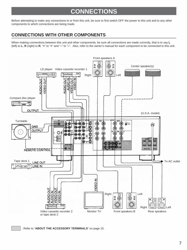
CONNECTIONSBefore attempting to make any connections to or from this unit, be sure to first switch OFF the power to this unit and to any othercomponents to which connections are being made.
CONNECTIONS WITH OTHER COMPONENTS
When making connections between this unit and other components, be sure all connections are made correctly, that is to say L(left) to L, R (right) to R, “+” to “+” and “–” to “–”. Also, refer to the owner’s manual for each component to be connected to this unit.
: Refer to “ABOUT THE ACCESSORY TERMINALS” on page 10.
LD player Video cassette recorder 1
Compact disc player
Turntable
Tape deck 1
Video cassette recorder 2or tape deck 2
Monitor TV Front speakers B
Right Left
Right Left
To AC outlet
(U.S.A. model)
Rear speakers
Front speakers A
Center speaker(s)
Right Left

8
CONNECTING S VIDEO TERMINALSIf your video cassette recorder, video disc player, etc. and your monitor are equipped with “S” (high-resolution) video terminals,connect them to this unit’s S VIDEO terminals, and connect this unit’s S VIDEO MONITOR OUT terminal to the “S” video input ofyour monitor. Otherwise, connect the composite video terminals from your video cassette recorder, video disc player, etc. to thecomposite video terminals of this unit, and connect this unit’s composite MONITOR OUT terminal to the composite video input ofyour monitor.
NoteIf video signals are sent to both S VIDEO input and composite input terminals, the signals will be sent to their respectiveoutput terminals independently.
ON SCREEN DISPLAYS
If you connect your video cassette recorder, video disc player, video monitor, etc. to this unit, you can take advantage of this unit’scapability to display DSP program names and information about other various settings and adjustments on your video monitor’sscreen. This information will be superimposed over the video image.If there is no video source connected or it is turned off, the information will be displayed over a monochromatic background.
Notes If you watch a video source that is connected to both S VIDEO and composite video input terminals of this unit, signals of screen
display information are output from only the S VIDEO MONITOR OUT terminal. When no video signal is input to either S VIDEO input or composite video input terminals of this unit, signals of screen display
information are output from both S VIDEO MONITOR OUT and composite MONITOR OUT terminals with a monochromaticbackground.* For the General Model, if the PAL/NTSC switch on the rear panel is set to “PAL”, nothing will be output from either S VIDEO
MONITOR OUT or composite MONITOR OUT terminal in this case.
LD player
Video cassette recorder 1Video cassette recorder 2
Monitor TV

9
Connect the SPEAKERS terminals to your speakers with wireof the proper gauge, cut to be as short as possible. If theconnections are faulty, no sound will be heard from thespeakers. Make sure that the polarity of the speaker wires iscorrect, that is, + and – markings are observed. If these wiresare reversed, the sound will be unnatural and will lack bass.Do not let the bare speaker wires touch each other and donot let them touch the metal parts of this unit as this coulddamage this unit and/or speakers. Use speakers with the specified impedance shown on the
rear of this unit.
How to Connect:
Red: positive (+)Black: negative (–)
➀ Unscrew the knob.➁ Insert the bare wire.
[Remove approx. 5mm(1/4") insulation fromthe speaker wires.]
➂ Tighten the knob andsecure the wire.
* Banana Plug connections are also possible. Simply insert theBanana Plug connector into the corresponding terminal.
Front speaker connection:One or two speaker systems can be connected to this unit. Ifyou connect only one speaker system, connect it to either theFRONT A or B terminals.
Rear speaker connection:One rear speaker system can be connected to the REARterminals.
Center speaker connection:One or two center speakers can be connected to this unit. Ifyou connect only one center speaker, connect it to either theCENTER C or D terminals.While connecting, be sure to set the CENTER speakerimpedance switch to the proper position.Set to “C + D” when using two center speakers, or to “C OR D”when using only one center speaker. If the switch is set to theimproper position, no sound may be heard from the centerspeaker.
CONNECTING SPEAKERS
USING AUX TERMINALS (ON THE FRONT PANEL) <for RX-V1070 only>These terminals are used to connect an auxiliary videoinput source such as a camcorder to this unit.
23
1C D
C OR D
L
R
VIDEO
AUDIO OUT
AUDIO OUT
VIDEO OUTCamcorder

10
ABOUT THE ACCESSORY TERMINALS
AC OUTLETS(U.S.A., Canada and General models)......... 2 SWITCHED OUTLETS and 1 UNSWITCHED OUTLET(Australia model) ...................................1 SWITCHED OUTLETUse these to connect the power cords from your componentsto this unit.The power to the SWITCHED outlets is controlled by this unit’sPOWER switch or the provided remote control transmitter’sPOWER key. These outlets will supply power to anycomponent whenever this unit is turned on.The power to the UNSWITCHED outlet can not be controlledby this unit’s POWER switch or the provided remote controltransmitter’s POWER key.
<U.S.A. and General models>The maximum power (total power consumption ofcomponents) that can be connected to the SWITCHED ACOUTLETS is 100 watts.The maximum power (total power consumption ofcomponents) that can be connected to the UNSWITCHED ACOUTLET is 200 watts.
<Canada model>The maximum power (total power consumption ofcomponents) that can be connected to the SWITCHED ACOUTLETS is 120 watts.The maximum power (total power consumption ofcomponents) that can be connected to the UNSWITCHED ACOUTLET is 180 watts.
<Australia model>The maximum power (total power consumption ofcomponents) that can be connected to the SWITCHED ACOUTLET is 100 watts.
REMOTE CONTROL (PHONO) connectorIf you have a YAMAHA turntable with the terminal for remotecontrol, connect it to this connector by using the cable providedwith the turntable. This connection allows you to control theturntable from the provided remote control transmitter.
GND terminal (For turntable use) Connecting the ground wire of the turntable to this terminal willminimize hum, but in some cases better results may beobtained with the ground wire disconnected.
FRONT OUT terminalsThese terminals are for front-channel line output. Leave thejumper bars connected to FRONT IN terminals when you usethe built-in amplifier.However, if you drive front speakers with an external stereopower amplifier, remove the jumper bars and connect the inputterminals of the external amplifier (MAIN IN or AUX terminalsof a power amplifier or an integrated amplifier) to theseterminals.
FRONT IN terminalsThese terminals are for line input to the built-in front-channelamplifier. Leave the jumper bars connected to FRONT OUTterminals when you use the built-in amplifier.However, if you drive front speakers with an external stereopower amplifier, remove the jumper bars.
REAR OUT terminalsThese terminals are for rear-channel line output. If you use thebuilt-in amplifier, there is no connection to these terminals.However, if you drive rear speakers with an external stereopower amplifier, connect the input terminals of the externalamplifier to these terminals.If you use the built-in amplifier and the external power amplifierat the same time, the sound will be output only through theexternal one.
CENTER OUT terminalThis terminal is for center-channel line output. There is noconnection to this terminal when you use the built-in amplifier.However, if you drive a center speaker with an external poweramplifier, connect the input terminal of the external amplifier tothis terminal.If you use the built-in amplifier and the external power amplifierat the same time, the sound will be output only through theexternal one.
LOW PASS terminalThis terminal is for output to a mono amplifier driving asubwoofer. Frequencies above 200 Hz are filtered out so thatonly the bass range remains.

11
EN
GL
ISH
ANTENNA CONNECTIONS
Each antenna should be connected to the designated terminals correctly, referring to the following figure. Both AM and FM indoor antennas are included with this unit. In general, these antennas will probably provide sufficient signal
strength. Nevertheless, a properly installed outdoor antenna will give clearer reception than an indoor one. If you experiencepoor reception quality, an outdoor antenna may result in improvement.
Connecting the AM loop antenna
* The AM loop antenna should be placed apart from the main unit. The antenna may be hung on a wall.* The AM loop antenna should be kept connected, even if an outdoor AM antenna is connected to this unit.
GND terminalFor maximum safety and minimum interference, connect theGND terminal to a good grounding. A good grounding is ametal stake driven into moist earth.
Notes When connecting the indoor
FM antenna, make sure thatthe grooved part of theconnector hole is facingdownward.
If you need an outdoor FM antenna to improve FM receptionquality, either a 300-ohm feeder or a coaxial cable may beused. In locations troubled by electrical interference, acoaxial cable is preferable.
Outdoor FM antenna Indoor FMantenna(included)
AM loopantenna(included)
75-ohm/300-ohmantenna adapter
75-ohmcoaxialcable
300-ohmfeeder
Ground
Outdoor AM antenna
1 2 3➀
➁
➂Orient so that the bestreception is obtained.
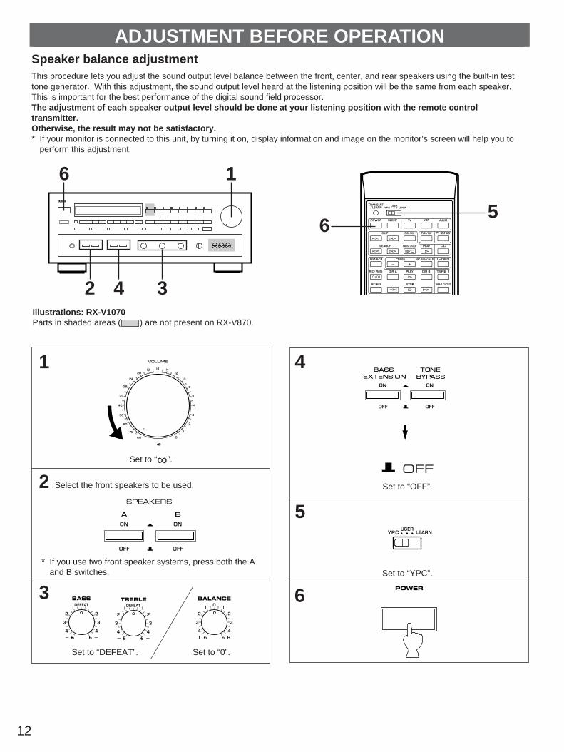
1
Set to “∞”.
2 Select the front speakers to be used.
* If you use two front speaker systems, press both the Aand B switches.
3
Set to “DEFEAT”. Set to “0”.
4
Set to “OFF”.
5
Set to “YPC”.
6
12
Speaker balance adjustmentThis procedure lets you adjust the sound output level balance between the front, center, and rear speakers using the built-in testtone generator. With this adjustment, the sound output level heard at the listening position will be the same from each speaker.This is important for the best performance of the digital sound field processor.The adjustment of each speaker output level should be done at your listening position with the remote controltransmitter.Otherwise, the result may not be satisfactory.* If your monitor is connected to this unit, by turning it on, display information and image on the monitor’s screen will help you to
perform this adjustment.
ADJUSTMENT BEFORE OPERATION
Illustrations: RX-V1070Parts in shaded areas ( ) are not present on RX-V870.
6
2 4 3
1
65
SPEAKERS
BASS TREBLE BALANCE
OFF
POWER

Turn up the volume by using the remote controltransmitter. You will hear a test tone (like pink noise)from the left front speaker, then the center speaker,then the right front speaker, and then the rearspeakers, for about two seconds each. The displaychanges as shown below.
* If your monitor is on, the state of test tone output is alsoshown by an image of audio listening room on themonitor’s screen.
* The test tone from the left rear speaker and the right rearspeaker will be heard at the same time.
13
For detailed information on the remote control transmitter, refer to “REMOTE CONTROL TRANSMITTER” on page 25.
Select the center mode according to your speakerconfiguration.(Refer to “SPEAKER CONFIGURATION” on page 6.)
On the feature of each mode, refer to the “Note” shownbelow.
NoteIn step 8, when you select the center mode, note the following.
For 5 speaker configuration)NORMAL: Select this mode when you use a center speaker
that is smaller than the front speakers. In thismode, the bass tone will be output from the frontspeakers.
WIDE: Select this mode when you use the center speakerapproximately same sized as the front speakers.
For 4 speaker configuration)PHANTOM: Select this mode when you do not use the center
speaker. The center sound will be output from theleft and right front speakers.
7
8
9
10
Illustrations: RX-V1070Parts in shaded areas ( ) are not present on RX-V870.
10
97
10
7
8
ou
CENTERMODE NORMAL
WIDE
PHANTOM
NORMAL
Flashes continuously.
Front (L) Center
Rear(L and R)
Front (R)

14
Adjust the BALANCE control so that the effect soundoutput level of the left front speaker and the right frontspeaker are the same.
Make the sound output level of the center speaker thesame as that of the front speakers with the CENTERLEVEL key.
Make the sound output level of the rear speakers thesame as that of the front speakers with the REARLEVEL key.
Cancel the test tone.
Notes The FRONT EFFECT LEVEL key does not function if the
unit is in the “test” mode. Because the effect sound outputlevel of the front speakers is used as the basis in speakerbalance adjustment.
Once you have completed these adjustments, you canadjust whole sound level on your audio system by using theVOLUME control (or the MASTER VOLUME keys on theremote control transmitter).
If you use external power amplifiers, their volume controlsmay also be adjusted to achieve proper balance.
In step 12, if the center mode is in the “PHANTOM” position,the sound output level of the center speaker can not beadjusted. This is because in this mode, the center sound isautomatically output from the left and right front speakers.
11
12
13
14
Illustrations: RX-V1070Parts in shaded areas ( ) are not present on RX-V870.
1
14
1213
BALANCE
NORMAL
C
Illuminates. Adjustable
NORMAL
R
Illuminates. Adjustable
NORMAL
Stops flashing and disappears.

Set to the “∞” position.
Select the desired input source with the input selectorswitches. (For video sources, turn the TV/monitor ON.)
* The indicator corresponding to theselected input source will illuminate.
Select the front speakers to be used.
* If you use two front speaker systems, press both the Aand B switches.
Play the source. (For detailed information on the tuningoperation, refer to the page 17.)
Adjust to the desired output level.
15
OPERATIONS
If desired, adjust the BASS, TREBLE, BALANCEcontrols, etc. (refer to page 16) and use the digitalsound field processor. (Refer to page 19.)
To play a source
1
2
3
4
5
6
7
Select the source to be recorded.
* “AUX” is not present on RX-V870.
Play the source.
Confirm the source by selecting it with the inputselector switch and turning up the VOLUME control.
Set the tape deck or VCR to the recording mode.
If your tape deck has three head monitoring capability,you can monitor the signal just recorded by selectingthe tape deck in the recording mode with the inputselector switch.
* Also, refer to the manual of the tape deck being used.
To record a source to tape (or dub from atape to another)
11
2233
44
55
Notes• If you want to enjoy another source while recording, select it
with the input selector switch.• Adjusting the VOLUME, BASS, TREBLE, BALANCE
controls, BASS EXTENSION and TONE BYPASS switchand operating the digital sound field processor duringrecording have no effect on the material being recorded.
Illustrations: RX-V1070Parts in shaded areas ( ) are not present on RX-V870.
PHONES jack
TONE BYPASSBASS EXTENSION
Tuner controls7
2
4
3, 33, 55
1, 6, 33117
POWER
SPEAKERS

16
Adjust the balance of the output volume to the left and rightspeakers to compensate for sound imbalance caused byspeaker location or listening room conditions.
NoteThis control is effective only for the sound from the frontspeakers.
BASS : Turn this clockwise to increase (or counter-clockwise to decrease) the low frequency response.
TREBLE : Turn this clockwise to increase (or counter-clockwise to decrease) the high frequency response.
NoteThese controls are effective only for the sound from the frontspeakers.
Because one or two speaker systems (as front speakers) canbe connected to this unit, the SPEAKERS switches allow youto select speaker system A or B, or both at once.
Press this switch to revert instantly to the flat states of theBASS and TREBLE controls without changing the setting ofthese controls.
You can boost bass frequency response by setting this switchto the “ON” position. This switch is effective only on the soundfrom the front speakers.
When you listen with headphonesConnect the headphones to the PHONES jack. You can listento the main sound through headphones. When listening withheadphones privately, set both the SPEAKERS A and Bswitches to the OFF position.
Adjusting the BALANCE control
Adjusting the BASS and TREBLEcontrols
Selecting the SPEAKER system
Using the TONE BYPASS switch
Using the BASS EXTENSION switch
BALANCE
BASS TREBLE
SPEAKERS
PHONES

17
TUNING OPERATIONSNormally, if station signals are strong and there is no interference, quick automatic-search tuning (AUTOMATIC TUNING) is possible.However, if signals of the station you want to select are weak, you must tune to it manually (MANUAL TUNING).
Display information ➀ Displays the band and frequency of the received station.➁ Illuminates when an FM stereo broadcast with sufficient
signal strength is received.➂ Indicates the signal level of the received station.
Select the reception band (FM or AM) while watchingthe display.
To tune to a higher frequency, press the right side once.To tune to a lower frequency, press the left side once.
If the station where tuning search stopped is not thedesired one, follow step 3 again.
* If the tuning search does not stop at the desired station(because the signals of the station are weak), change tothe MANUAL TUNING method.
Select the reception band (FM or AM) while watchingthe display.
Tune to the desired station manually.
* To continue tuning search, press and hold the button.
NoteIf you tune to a FM station manually, it is received in monauralmode automatically to increase the signal quality.
AUTOMATIC TUNING MANUAL TUNING
1
2
3
4
11
22
33
Illustrations: RX-V1070Parts in shaded areas ( ) are not present on RX-V870.
1, 11
3, 4, 33 2, 22
AM FMou AM FMou
AUTO/MAN'L MONO AUTO/MAN'L MONO
kHZFM
AUTO
MHz“AUTO TUNING”goes off.
STEREO
0MHz 40 60 80 100FM
1 2 3

Notes A new setting can be programmed in place of the former
one. For presets, the setting of the reception mode (stereo or
monaural) is stored along with the station frequency.
Memory back-upThe memory back-up circuit prevents the programmed datafrom being lost even if the POWER switch is turned off or thepower plug is disconnected from the AC outlet or the power iscut due to temporary power failure. If, however, the power is cut for more than two weeks, the memory may be erased. Ifso, it can be re-programmed simply by following the PRESETTUNING steps.
18
PRESET TUNINGThis unit can store station frequencies (selected by tuning operation) by using preset station buttons. With this function, you canselect any desired station simply by pressing the corresponding preset station button. Up to 40 stations (8 stations per page) canbe programmed.
Tune to the desired station. (Refer to the previous page for tuning procedures.)
Select the desired page (A – E) of preset stationbuttons while watching the display.
Press a preset station button before “MEMORY” goesoff from the display.
* In the same way, program other stations to A2, A3 ... A8.* You can program more stations to the preset station buttons on
other pages in the same way by selecting other pages in step 2.
Select the page of preset station buttons.
Select the desired preset station button.
To program stations To recall a preset station
1
2
3
4
11
22
Illustrations: RX-V1070Parts in shaded areas ( ) are not present on RX-V870.
2, 11
3
4, 22 (Preset station buttons)
A/B/C/D/EPRESET
FM
AUTO
A/B/C/D/EPRESET
FM
AUTO
MEMORYSTEREO
0MHz 40 60 80 100
MEMORYCONCERT
HALL
PRESET STEREO
0MHz 40 60 80 100FM
AUTO
CONCERTHALL
Shows the displayed stationhas been programmed to A1.
Flashes for about 5 seconds.

19
USING DIGITAL SOUND FIELD PROCESSOR (DSP)This unit incorporates a sophisticated, multi-program digital sound field processor, which allows you to expand and shape the audiosound field from both the audio and video sources, for a theater-like experience in the listening/viewing room.This digital sound field processor has 8 programs; 4 programs for audio sources and 4 programs for Audio/Video sources. You cancreate an excellent audio sound field by selecting the suitable program and adding desired adjustments. In addition, when thedigital sound field program is in the DOLBY PRO LOGIC, ENHANCED or 70 mm MOVIE THEATER mode, the built-in automaticinput balance control functions. This presents you the best surround condition without manual adjustment.
PHANTOM
PRESET STEREO
0kHZ
MHz 40 60 80 100
MEMORY
AMFM
AUTO
PRO LOGIC
NORMALWIDE
F RC
DELAY
ms
SLEEP MOVIE THEATERENHANCED70 mm TV
THEATERROCK
CONCERT JAZZ CLUB CHURCHCONCERT
HALL
Selects center mode.(For details,refer to page 13.)
Used to adjust thedelay time. (For details,refer to page 22.)
Used to adjust sound outputlevel of each speaker.(For details, refer to page 22–23.)
Displays your selection onthe DSP or other informations.
Digital soundfield programselector
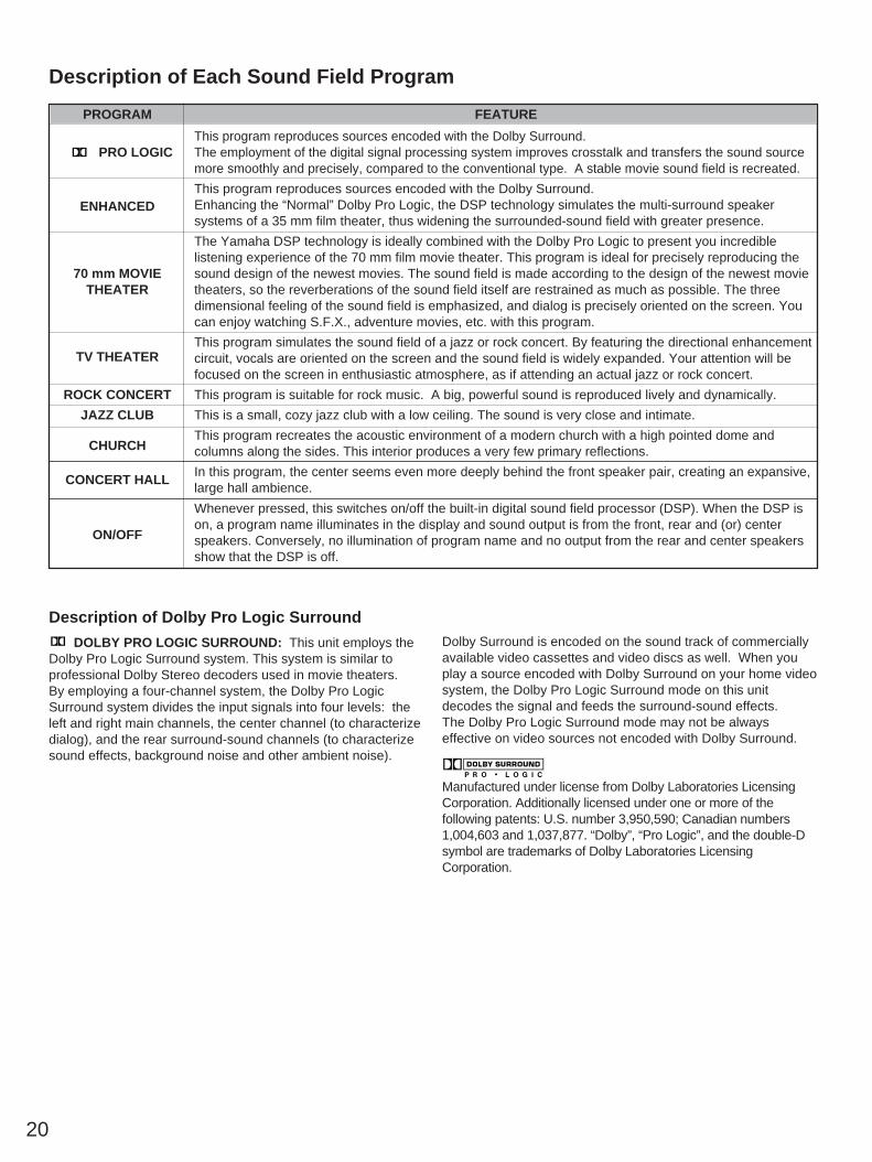
Description of Each Sound Field Program
PROGRAM FEATURE
This program reproduces sources encoded with the Dolby Surround.PRO LOGIC The employment of the digital signal processing system improves crosstalk and transfers the sound source
more smoothly and precisely, compared to the conventional type. A stable movie sound field is recreated.
This program reproduces sources encoded with the Dolby Surround.ENHANCED Enhancing the “Normal” Dolby Pro Logic, the DSP technology simulates the multi-surround speaker
systems of a 35 mm film theater, thus widening the surrounded-sound field with greater presence.
70 mm MOVIE
The Yamaha DSP technology is ideally combined with the Dolby Pro Logic to present you incredible
THEATER
listening experience of the 70 mm film movie theater. This program is ideal for precisely reproducing thesound design of the newest movies. The sound field is made according to the design of the newest movietheaters, so the reverberations of the sound field itself are restrained as much as possible. The threedimensional feeling of the sound field is emphasized, and dialog is precisely oriented on the screen. Youcan enjoy watching S.F.X., adventure movies, etc. with this program.
TV THEATERThis program simulates the sound field of a jazz or rock concert. By featuring the directional enhancementcircuit, vocals are oriented on the screen and the sound field is widely expanded. Your attention will befocused on the screen in enthusiastic atmosphere, as if attending an actual jazz or rock concert.
ROCK CONCERT This program is suitable for rock music. A big, powerful sound is reproduced lively and dynamically.
JAZZ CLUB This is a small, cozy jazz club with a low ceiling. The sound is very close and intimate.
CHURCHThis program recreates the acoustic environment of a modern church with a high pointed dome andcolumns along the sides. This interior produces a very few primary reflections.
CONCERT HALLIn this program, the center seems even more deeply behind the front speaker pair, creating an expansive,large hall ambience.
ON/OFF
Whenever pressed, this switches on/off the built-in digital sound field processor (DSP). When the DSP ison, a program name illuminates in the display and sound output is from the front, rear and (or) centerspeakers. Conversely, no illumination of program name and no output from the rear and center speakersshow that the DSP is off.
Description of Dolby Pro Logic Surround
DOLBY PRO LOGIC SURROUND: This unit employs theDolby Pro Logic Surround system. This system is similar toprofessional Dolby Stereo decoders used in movie theaters.By employing a four-channel system, the Dolby Pro LogicSurround system divides the input signals into four levels: theleft and right main channels, the center channel (to characterizedialog), and the rear surround-sound channels (to characterizesound effects, background noise and other ambient noise).
Dolby Surround is encoded on the sound track of commerciallyavailable video cassettes and video discs as well. When youplay a source encoded with Dolby Surround on your home videosystem, the Dolby Pro Logic Surround mode on this unitdecodes the signal and feeds the surround-sound effects.The Dolby Pro Logic Surround mode may not be alwayseffective on video sources not encoded with Dolby Surround.
Manufactured under license from Dolby Laboratories LicensingCorporation. Additionally licensed under one or more of thefollowing patents: U.S. number 3,950,590; Canadian numbers1,004,603 and 1,037,877. “Dolby”, “Pro Logic”, and the double-Dsymbol are trademarks of Dolby Laboratories LicensingCorporation.
20

21
Follow step 1–6 shown in “OPERATIONS” on page 15.
Select the desired program that is suitable for thesource.
The corresponding indicator will illuminate.
If desired, adjust the delay time and the output level ofeach speaker. (For details, refer to the correspondingdescriptions on page 22–23.)
Notes If you prefer to cancel the selected program, press the
ON/OFF switch. The sound will be the normal 2-channelstereo without surround sound effect.
In the ROCK CONCERT, JAZZ CLUB, CHURCH andCONCERT HALL modes, no sound is heard from the centerspeaker.
When a monaural sound source is played in the DOLBYPRO LOGIC or ENHANCED mode, no sound is heard fromthe front speakers and the rear speakers. Sound is heardonly from the center speaker. However, if the center modeis in the PHANTOM, the front speakers output the sound ofthe center speaker.
If you connect an external amplifier to this unit, see if it hasbuilt-in surround sound or ambience circuitry. If it does,then be sure that the surround or ambience circuitry on thatamplifier is off while you are using the digital sound fieldprocessor’s Dolby Pro Logic Surround decoding function.
When this unit is in the Dolby Pro Logic Surround mode, ifthe main-source sound is considerably altered byoveradjustment of the BASS, TREBLE controls or BASSEXTENSION switch, the relationship between the centerand rear channels may produce an unnatural effect.
1
2
3
To play a source with the digital sound field processor
Illustrations: RX-V1070Parts in shaded areas ( ) are not present on RX-V870. 2
3
PRO LOGIC

Adjustment of the CENTER LEVEL
Adjustment of the FRONT EFFECT LEVEL
If desired, you can adjust the effect sound output level of thefront speakers with this control. The output level is preset to be80. However, you can adjust the level between 1 and 100.
If the digital sound field program is in the DOLBY PROLOGIC mode, the FRONT EFFECT LEVEL control does notfunction.
Once the output level is adjusted, the level value will be thesame in all the digital sound field programs except for theDOLBY PRO LOGIC .
If a digital sound field program is not used, the FRONTEFFECT LEVEL control does not function.
If desired, you can adjust the sound output level of the centerspeaker with this control even if the output level is already setin “Speaker balance adjustment” on page 12.
By continuously pressing “+” or “–” on the CENTER LEVELcontrol, the level value changes continuously. However, thevalue stops changing momentarily at the point which wasonce set in the “test” mode.
If the digital sound field program is in the ROCK CONCERT,JAZZ CLUB, CHURCH or CONCERT HALL mode, theCENTER LEVEL control can not function.
Once the output level is adjusted, the level value will be thesame in all the digital sound field programs except theabove-mentioned ones.
If a digital sound field program is not used, the CENTERLEVEL control does not function.
22
Adjustment of DELAY TIME
You can adjust the time difference between the beginning ofthe source sound and the beginning of the effect sound withthe DELAY TIME control.The DELAY TIME control is effective with all programs.By applying more or less delay, sound effects, backgroundnoise, and ambient noise coming at you from the rear speakerscan be enhanced or subdued for extra effect.
1. PRO LOGIC: from 15 to 30 milliseconds(Preset value: 20 milliseconds)
2. ENHANCED: from 15 to 30 milliseconds(Preset value: 20 milliseconds)
3. 70 mm MOVIE from 15 to 30 millisecondsTHEATER: (Preset value: 10 milliseconds)
4. TV THEATER: from 1 to 50 milliseconds(Preset value: 10 milliseconds)
5. ROCK CONCERT: from 1 to 50 milliseconds(Preset value: 15 milliseconds)
6. JAZZ CLUB: from 1 to 50 milliseconds(Preset value: 11 milliseconds)
7. CHURCH: from 1 to 50 milliseconds(Preset value: 40 milliseconds)
8. CONCERT HALL: from 1 to 50 milliseconds(Preset value: 30 milliseconds)
By continuously pressing “+” or “–” on the DELAY TIMEcontrol, the value changes continuously.However, the value stops changing momentarily at thepreset point.
NoteAdding too much delay will cause an unnatural effect withsome sources. Experiment with the DELAY TIME control tocreate the effect that you find most suitable.
DELAY TIMEDELAY
ms
Adjustable.
F
Adjustable.Illuminates.
FRONT EFFECT LEVEL
C
Adjustable.Illuminates.
CENTER LEVEL

23
EN
GL
ISH
Adjustment of the REAR LEVEL
If desired, you can adjust the sound output level of the rearspeakers with this control even if the output level is already setin “Speaker balance adjustment” on page 12.
By continuously pressing “+” or “–” on the REAR LEVELcontrol, the level value changes continuously. However, thevalue stops changing momentarily at the point which wasonce set in the “test” mode.
Once the output level is adjusted, the level value will be thesame in all the digital sound field programs.
If a digital sound field program is not used, the REARLEVEL control does not function.
NoteThe values of the DELAY TIME, the FRONT EFFECT LEVEL,CENTER LEVEL, and REAR LEVEL you set the last time willremain memorized even when the power of this unit is off.However, if the power plug cord is kept disconnected for morethan one week, these values will be invalid.
R
Adjustable.Illuminates.
REAR LEVEL

24
SETTING THE SLEEP TIMERIf you use the SLEEP timer of this unit, you can set this unit to be turned off automatically. When you are going to sleep whileenjoying a broadcast or other desired input source, this timer function is helpful.
Notes The SLEEP timer can be controlled only with the remote control transmitter. The components on which the SLEEP timer is effective are the sources connected to a SWITCHED OUTLET on the rear panel
of this unit.
Select the desired SLEEP time. Whenever the SLEEP keyis pressed, the SLEEP time will change as follows.
After a while, the display returns to the indication beforethe SLEEP timer is set, and the “SLEEP” indicator stopsflashing and illuminates.
The unit will be turned off automatically after thepassing of the SLEEP time you selected.
To set the SLEEP time To cancel the selected SLEEP time
1
2
Indicates the SLEEP time.
Flashes on and off continuously.
The SLEEP timer is OFF.(The indication before theSLEEP key is pressed.)
(Minutes)
Press once whenthe SLEEP time displays 30.
Returns to the indicationbefore the SLEEP timeris set.
Goes off.
SLEEP
120 90 60 30
SLEEP
25
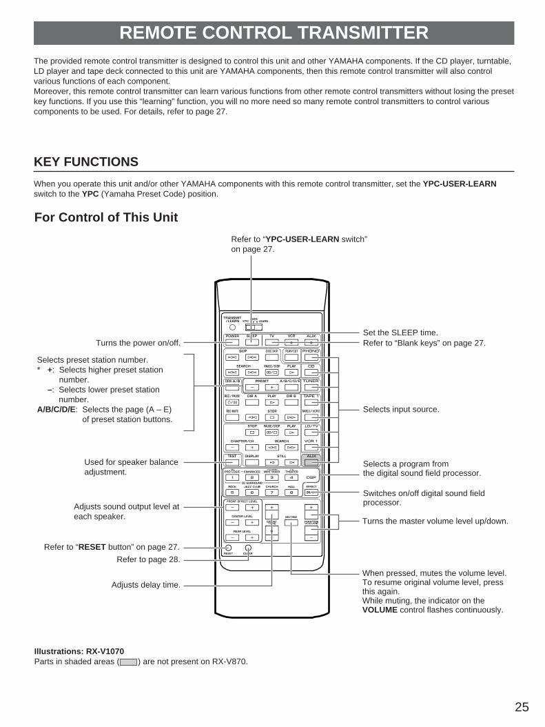
The provided remote control transmitter is designed to control this unit and other YAMAHA components. If the CD player, turntable,LD player and tape deck connected to this unit are YAMAHA components, then this remote control transmitter will also controlvarious functions of each component.Moreover, this remote control transmitter can learn various functions from other remote control transmitters without losing the presetkey functions. If you use this “learning” function, you will no more need so many remote control transmitters to control variouscomponents to be used. For details, refer to page 27.
KEY FUNCTIONS
When you operate this unit and/or other YAMAHA components with this remote control transmitter, set the YPC-USER-LEARNswitch to the YPC (Yamaha Preset Code) position.
REMOTE CONTROL TRANSMITTER
For Control of This Unit
Illustrations: RX-V1070Parts in shaded areas ( ) are not present on RX-V870.
Refer to “YPC-USER-LEARN switch”on page 27.
Set the SLEEP time.Refer to “Blank keys” on page 27.
Selects input source.
Used for speaker balanceadjustment.
Selects preset station number.* +: Selects higher preset station
number.–: Selects lower preset station
number.A/B/C/D/E: Selects the page (A – E)
of preset station buttons.
Adjusts sound output level ateach speaker.
Refer to “RESET button” on page 27.
Refer to page 28.
Adjusts delay time.
Selects a program fromthe digital sound field processor.
Switches on/off digital sound fieldprocessor.
Turns the master volume level up/down.
When pressed, mutes the volume level.To resume original volume level, pressthis again.While muting, the indicator on theVOLUME control flashes continuously.
Turns the power on/off.

26
For Other Component ControlIdentify the remote control transmitter keys with your component’s keys. If these keys are identical, their function will be the same.On each key function, refer to the corresponding instruction on your component’s manual.
Illustrations: RX-V1070Parts in shaded areas ( ) are not present on RX-V870.
Starts/stops record play on turntable.Controls the compact disc player.* DISC SKIP is applicable only
to a compact disc changer.
Controls the LD player
Controls the tape deck.* DIR A, B and DECK A/B are
applicable only to a doublecassette tape deck.
* For a single cassette deck withautomatic reverse function,pressing DIR A will reverse thedirection of tape running.

27
REMOTE CONTROL “LEARNING” FUNCTION
The keys on this remote control transmitter can be programmed to “learn” key-functions from other remote control transmitters. Byusing this feature, this unit can then be used in place of one or more other remote control transmitters, thus making operation ofyour various audio and video components more convenient. Use the included user program sheets to indicate a new functionlearned for each key.
NoteThere may occasionally be instances in which, due to the signal-coding and modulation employed by the other remote controltransmitter, this unit will not be able to “learn” its signals.
Set to the “LEARN” position.
Press a key on this unit where a new function will belearned.
Press and hold the key (on the other remote controltransmitter) where the desired new function is.
When the TRANSMIT/LEARN indicator stops illuminating,the learning is finished.
Repeat step 2–3 until all desired functions aresuccessfully learned.
Set to the “USER” position.
Try operating your components.
Notes When you operate the desired component with this remote
control transmitter, TRANSMIT/LEARN indicator will flashsteadily.
The originally preset function of a key is still available in theUSER position if a new function has not been learned to thekey.
Successful learning to a key results in the erasure ofpreviously learned functions and their replacement by thenewly learned ones.
If there is no more room in the memory area for a function tobe learned, the TRANSMIT/LEARN indicator will flash twotimes. In this case, even if some keys are not occupied withfunctions from other remote control transmitters, no furtherlearning is possible.
Memory back-upAll of the learned functions will be retained while you replacethe batteries. However, if no batteries are installed for a fewhours, the learned functions will be erased and will have to belearned again.
Blank keys (Refer to page 25.)These keys have no preset functions and are used only forlearning other remote control transmitter’s functions.
YPC-USER-LEARN switch (Refer to page 25.)YPC: Set to this position when using preset key functions
(for controlling this unit and/or YAMAHAcomponents).* “YPC” is the abbreviation of YAMAHA Preset
Code.USER: Set to this position when using “learned” key
functions.LEARN: Set to this position when learning new key functions
from other remote control transmitters.
RESET button (Refer to page 25.)Press this button to “reset” the internal microcomputer whichcontrols remote control operations. Microcomputer “reset” isnecessary when the remote control freezes.* Pressing the RESET button will not erase learned functions.
To Learn a New Function
1
2
3
4
5
About 5–10 cm (2–4 in.)
Other remotecontrol transmitter
This unit

28
NOTES ABOUT THE REMOTE CONTROL TRANSMITTER
Battery installation
Battery replacement
If you find that the remote control transmitter must be usedcloser to the main unit, the batteries are weak. Replace bothbatteries with new ones.Notes Use only AA, R6, UM-3 batteries for replacement. Be sure the polarities are correct. (See the illustration inside
the battery compartment.) Remove the batteries if the remote control transmitter will
not be used for an extended period of time. If batteries leak, dispose of them immediately. Avoid
touching the leaked material or letting it come in contact withclothing, etc. Clean the battery compartment thoroughlybefore installing new batteries.
Remote control transmitter operation range
Notes There should be no large obstacles between the remote
control transmitter and the main unit. If the remote control sensor is directly illuminated by strong
lighting (especially an inverter type of fluorescent lamp etc.),it might cause the remote control transmitter not to workcorrectly. In this case, reposition the main unit to avoiddirect lighting.
Set to the “USER” position.
Press and hold the CLEAR button using the point of amechanical pencil, etc.
Press and hold the key where the learned function tobe deleted is until the indicator flashes 3 times.
To clear two or more functions, repeat step 2 and 3.
NoteIf a key is not pressed soon after the CLEAR button is pressed,this unit will automatically return to the status that was in effectbefore the CLEAR button was pressed.
Set to the “LEARN” position.
Press and hold the CLEAR button using the point of amechanical pencil, etc.
Press and hold any key until the indicator flashes 7times.
To Clear a Learned Function To Clear All Learned Functions
1
2
3
1
2
3
CLEAR
TRANSMIT/LEARN
CLEAR
TRANSMIT/LEARN
1
2
3
30° 30°
Remote controlsensor
Within approximately7 m (23 feet)

29
Am
plif
ier
FM
AM
Oth
ers
Rem
ote
co
ntr
ol t
ran
smit
ter
TROUBLESHOOTING
If the unit fails to operate normally, check the following points to determine whether the fault can be corrected by the simplemeasures suggested. If it cannot be corrected, or if the fault is not listed in the SYMPTOM column, disconnect the power cord andcontact your authorized YAMAHA dealer or service center for help.
CAUSE
Power cord is not plugged in or is not completelyinserted.
Incorrect output cord connections.
The MUTING switch is ON.
Appropriate input selector is not pressed.
The protection circuit has activated because ofshort circuit etc.
Incorrect setting of the BALANCE control.
Incorrect cord connection.
Incorrect cord connections.
No connection from the turntable to the GNDterminal.
The record is being played on a turntable with anMC cartridge.
The sound output level of the rear speakers is 0.
The monaural sound source is played in DOLBYPRO LOGIC or ENHANCED mode.
The sound output level of the center speaker is 0.
The center mode is in PHANTOM mode.
Incorrect sound field program selection.
No sound field program is selected.
Because of the characteristics of FM stereobroadcasts, this is limited to cases where thetransmitter is too far away or the antenna input ispoor.
There is multipath interference.
The station is too weak.
Weak signal or loose antenna connections.
Noises will result from ligtning, fluorescent lamps,motors, thermostats and other electrical equipment.
A television set is being used nearby.
Direct sunlight or lighting (of an inverter type offlourescent lamp etc.) is striking the remote controlsensor of the main unit.
The batteries of this remote control transmitter areweak.
The batteries of this remote control transmitterand/or the other remote control transmitter areweak.
The distance between the two remote controltransmitters is too long or too short.
The signal coding or modulation of the other remotecontrol transmitter is not compatible with this remotecontrol transmitter.
Memory capacity is full.
The internal microcomputer “freezes”.
Power cord of this unit is not plugged in.
REMEDY
Firmly plug in the power cord.
Connect the cords properly. If the problem persists,the cords may be defective.
First, turn the volume control to full left. Then, turnthe MUTING switch OFF with the remote controltransmitter and adjust the volume.
Press the appropriate input selector correspondingto the input source.
Turning the unit off and then on will reset theprotection circuit.
Adjust it to the appropriate position.
Connect cord properly. If the problem persists, thecables may be defective.
Firmly connect the audio plugs. If the problempersists, the cord may be defective.
Make the GND connection between the turntableand this unit.
The player should be connected to the unit throughthe MC head amplifier.
Turn up the sound output level with the REARLEVEL key.
Select another program suitable for the monauralsound source.
Turn up the sound output level with the CENTERLEVEL key.
Select NORMAL or WIDE.
Select the appropriate program.
Check the antenna connections.Try using a multiple element FM antenna.
Adjust antenna placement to eliminate multipathinterference.
Use Manual tuning mode.Use a high quality directional FM antenna.
Tighten the AM loop antenna connections androtate it for best reception.
Use Manual tuning mode.
Use an outdoor antenna and a ground wire. Thiswill help somewhat but it is difficult to eliminate allnoise.
Relocate this unit away from the TV.
Change the position of the main unit.
Replace the batteries with new ones and press theRESET button on the remote control transmitter.
Replace the batteries (and press the RESET buttonfor this remote control transmitter).
Place the remote control transmitters with theproper distance.
Learning is not possible.
Further learning is not possible without deletingunnecessary commands.
Press the RESET button on the remote controltransmitter.
Plug in the power cord.
SYMPTOM
The unit fails to turn on when the POWERswitch is pressed.
No sound or no picture.
The sound suddenly goes off.
Only one side speaker outputs the sound.
Sound “hums”.
The volume level is low while playing a record.
No sound from the rear speakers.
No sound from the center speaker.
FM stereo reception is noisy.
There is distortion and clear reception cannotbe obtained even with a good FM antenna.
A desired station cannot be tuned in with Autotuning.
A desired station cannot be tuned in with Autotuning.
There are continuous crackling and hissingnoises.
There are buzzing and whining noises(especially in the evening).
The remote control transmitter does not work.
Learning cannot be made successfully.(The TRANSMIT/LEARN indicator does notilluminate or flash.)
The sound is degraded when monitoring isperformed by using the headphones connectedto the compact disc player or cassette deckwhich are connected with this unit.

30
SPECIFICATIONSAUDIO SECTION
Minimum RMS Output Power per ChannelFront L,R
8 ohms, 20 Hz to 20 kHz, 0.015% THD<RX-V1070>..................................110W+110W<RX-V870>........................................80W+80W
6 ohms, 20 Hz to 20 kHz, 0.015% THD<RX-V1070>..................................135W+135W<RX-V870>........................................95W+95W
Center8 ohms, 20 Hz to 20 kHz, 0.015% THD
<RX-V1070> .............................................110W<RX-V870> .................................................80W
6 ohms, 20 Hz to 20 kHz, 0.015% THD<RX-V1070> .............................................135W<RX-V870> .................................................95W
Rear L, R 8 ohms, 1 kHz, 0.08% THD
<RX-V1070>......................................30W+30W<RX-V870>........................................25W+25W
6 ohms, 1 kHz, 0.08% THD<RX-V1070>......................................40W+40W<RX-V870>........................................28W+28W
Dynamic Power per Channel(by IHF Dynamic Headroom measuring method)
8/6 ohms<RX-V1070> ...................................160W/190W<RX-V870> .....................................110W/140W
Dynamic Headroom8/6 ohms
<RX-V1070> .................................1.6 dB/2.0 dB<RX-V870> ...................................1.4 dB/1.7 dB
Input Sensitivity/ImpedancePHONO MM ...............................2.5 mV/47 k-ohmsCD/TUNER/TAPE/LD·TV/VCR....150 mV/47 k-ohmsAUX <RX-V1070 only>............150 mV/47 k-ohmsFRONT IN .........................................1V/47 k-ohms
Maximum Input Signal (1 kHz, 0.01% THD)PHONO MM..................................................90 mV
Output Level/ImpedanceREC OUT ...................................150 mV/470 ohmsFRONT OUT ....................................1V/3.3 k-ohmsLOW PASS ...................................0.8V/3.9 k-ohms
Maximum Voltage Output (1 kHz, 0.01% THD)FRONT OUT ....................................................4.8V
Headphone Jack Rated Output/Impedance8 ohms, 1 kHz, 0.01% THD Output Level.....................................................0.6VImpedance...............................................390 ohms
Frequency Response (20 Hz to 20 kHz)CD/TUNER/TAPE/LD·TV/VCR ...................0±1.5 dBAUX <RX-V1070 only> ...........................0±1.5 dBFRONT IN.................................................0±0.3 dB
RIAA Equalization DeviationPHONO MM..............................................0±0.5 dB
Total Harmonic Distortion (20 Hz to 20 kHz)PHONO MM to REC OUT (1V) .....................0.01%CD/TUNER/TAPE/LD·TV/VCR to FRONT OUT (1V)....................................................................0.008%AUX to FRONT OUT (1V) <RX-V1070 only>....................................................................0.008%FRONT IN to SP OUT
<RX-V1070>(50W/8 ohms) ......................................0.008%(60W/6 ohms) ......................................0.008%
<RX-V870>(40W/8 ohms) ......................................0.008%(50W/6 ohms) ......................................0.008%
Signal-to-Noise Ratio (IHF-A Network)PHONO MM (5 mV Input Shorted)......................................................More than 86 dBCD/TUNER/TAPE/LD·TV/VCR (Input Shorted)......................................................More than 93 dBAUX (Input Shorted) <RX-V1070 only>......................................................More than 93 dB
Residual Noise (IHF-A Network).....................150 µV
Channel Separation (Vol. –30 dB)PHONO MM (Input Shorted 1 kHz/10 kHz).............................................................60 dB/45 dBCD/TUNER/TAPE/LD·TV/VCR(Input 5.1 k-ohms Terminated 1 kHz/10 kHz).............................................................60 dB/45 dBAUX (Input 5.1 k-ohms Terminated 1 kHz/10 kHz)
<RX-V1070 only> ...........................60 dB/45 dB
Tone Control CharacteristicsBASS: Boost/cut ........................±10 dB (50 Hz)
Turnover Frequency ...................350 HzTREBLE: Boost/cut ..................±10 dB (20 kHz)
Turnover Frequency...............3.5 kHz
BASS EXTENSION..............................+7 dB (50 Hz)
Audio Muting........................................................–∞VIDEO
Video Signal Type[U.S.A. and Canada model] ........................NTSC[Australia model] ............................................PAL[General model] ..................................NTSC/PAL
Video Signal Level ............................1 Vp-p/75 ohms
S-Video Signal LevelY..................................................1 Vp-p/75 ohmsC ..........................................0.286 Vp-p/75 ohms
Maximum Input Level ..................More than 1.5 Vp-p
Signal-to-Noise Ratio ........................................50 dB
Frequency Response................5 Hz–10 MHz, –3 dB
FM SECTION
Tuning Range[U.S.A. and Canada models]................................................87.5 to 107.9 MHz[Australia and General models]............................................87.50 to 108.00 MHz
50 dB Quieting Sensitivity (IHF, 75 ohms)Mono ..........................................1.55 µV (15.1 dBf)Stereo............................................21 µV (37.7 dBf)
Usable Sensitivity (75 ohms)(30 dB S/N Quieting, 1 kHz, 100% mod.)
....................................................0.8 µV (9.3 dBf)
Image Response Ratio .....................................45 dB
IF Response Ratio ............................................80 dB
Spurious Response Ratio .................................70 dB
AM Suppression Ratio ......................................55 dB
Capture Ratio...................................................1.5 dB
Alternate Channel Selectivity ............................85 dB
Signal-to-Noise Ratio(IHF) Mono/Stereo ..............................81 dB/76 dB
Harmonic Distortion Mono/Stereo (1 kHz) .................................0.1/0.2%
Stereo Separation (1 kHz) ................................50 dB
Frequency Response20 Hz to 15 kHz .......................................0 ±1.5 dB
AM SECTION
Tuning Range[U.S.A., Canada and General models]..................................................530 to 1,710 kHz[Australia and General models]..................................................531 to 1,611 kHz
Usable Sensitivity .......................................100 µV/m
Selectivity..........................................................32 dB
Signal-to-Noise Ratio ........................................50 dB
Image Response Ratio .....................................40 dB
Spurious Response Ratio .................................50 dB
Harmonic Distortion............................................0.3%
AUDIO SECTIONOutput Level/Impedance
FM (100% mod., 1 kHz) .............700 mV/470 ohmsAM (30% mod., 400 Hz).............200 mV/470 ohms
GENERAL
Power Supply[U.S.A. and Canada models]....................................................AC 120V, 60 Hz[Australia model] .........................AC 240V, 50 Hz[General model]..........................AC 110/120/220/240V, 50/60 Hz
Power Consumption<RX-V1070>
[U.S.A., Australia and General models] ......400W[Canada model] .............................750 VA, 600W
<RX-V870>[U.S.A. model] .............................................300W[Australia and General models]...................350W[Canada model] .............................600 VA, 500W
AC Outlets[U.S.A. and General models]2 SWITCHED OUTLETS............100W max. total1 UNSWITCHED OUTLET.........200W max. total[Canada model]2 SWITCHED OUTLETS............120W max. total1 UNSWITCHED OUTLET.........180W max. total[Australia model]1 SWITCHED OUTLET ..............100W max. total
Dimensions (W x H x D).............................................435 x 171.5 x 468.5 mm
(17-1/8” x 6-3/4” x 18-7/16”)
Weight<RX-V1070> .....................18.6 kg (40 lbs. 15 oz.)<RX-V870> .........................14.8 kg (32 lbs. 9 oz.)
Accessories.....................................AM loop antennaIndoor FM antenna
Remote control transmitterBatteries
User program sheets
Specifications are subject to change without notice.

YAMAHA ELECTRONICS CORPORATION, USA 6660 ORANGETHORPE AVE., BUENA PARK, CALIF. 90620, U.S.A.YAMAHA CANADA MUSIC LTD. 135 MILNER AVE., SCARBOROUGH, ONTARIO M1S 3R1, CANADAYAMAHA ELECTRONIK EUROPA G.m.b.H. SIEMENSSTR. 22-34, D-25462 RELLINGEN BEI HAMBURG, F.R. OF GERMANYYAMAHA ELECTRONIQUE FRANCE S.A. RUE AMBROISE CROIZAT BP70 CROISSY-BEAUBOURG 77312 MARNE-LA-VALLEE CEDEX02, FRANCEYAMAHA ELECTRONICS (UK) LTD. YAMAHA HOUSE, 200 RICKMANSWORTH ROAD WATFORD, HERTS WD1 7JS, ENGLANDYAMAHA SCANDINAVIA A.B. J A WETTERGRENS GATA 1, BOX 30053, 400 43 VÄSTRA FRÖLUNDA, SWEDENYAMAHA MUSIC AUSTRALIA PTY, LTD. 17-33 MARKET ST., SOUTH MELBOURNE, 3205 VIC., AUSTRALIA VP63840-0 Printed in Japan BWWR,BB