Embed Size (px)
DESCRIPTION
rxi
Citation preview

Ericsson Wide Internal
DESCRIPTION 1 (65)Prepared (also subject responsible if other) No.
LMI/RR/RT Michelle McElvaney 1551-AXI 101 02 Uen Approved Checked Date Rev Reference
LMI/RR/RT Srdjan Krco 29/03/2005 H
RXI System Description
Abstract
This document describes the RXI 820 R5 and RXI 860 release in RAN P5. The document focuses on the hardware and software architectures, configuration, and the nodes role in the URAN network.
Keyword
RXI 820
RXI 860

Ericsson Wide Internal
DESCRIPTION 2 (65)Prepared (also subject responsible if other) No.
LMI/RR/RT Michelle McElvaney 1551-AXI 101 02 Uen Approved Checked Date Rev Reference
LMI/RR/RT Srdjan Krco 29/03/2005 H
Table of Contents
1 INTRODUCTION .......................................................................................................................................................... 3 1.1 REVISION HISTORY ................................................................................................................................................... 3 1.2 PURPOSE ................................................................................................................................................................... 4 1.3 SCOPE ....................................................................................................................................................................... 4
2 STRUCTURE.................................................................................................................................................................. 5
3 ATM CAPABILITIES OF THE RXI NODES............................................................................................................. 6 3.1 PROTOCOLS .............................................................................................................................................................. 8 3.2 SERVICE CATEGORIES............................................................................................................................................... 8 3.3 ATM BUFFERING ................................................................................................................................................... 11 3.4 ATM CROSS CONNECT FUNCTION ......................................................................................................................... 11 3.5 AAL1 CIRCUIT EMULATION FUNCTIONALITY......................................................................................................... 12 3.6 AAL2 FUNCTIONALITY........................................................................................................................................... 15 3.7 AAL5 FUNCTIONALITY........................................................................................................................................... 18 3.8 AAL0 FUNCTIONALITY........................................................................................................................................... 21 3.9 IMA........................................................................................................................................................................ 21 3.10 GPS AS A SYNCHRONIZATION REFERENCE ............................................................................................................. 23 3.11 MUB ROUTING........................................................................................................................................................ 24 3.12 HSDPA .................................................................................................................................................................. 27
4 ROLE IN THE NETWORK........................................................................................................................................ 27 4.1 RADIO ACCESS NETWORK AGGREGATOR ............................................................................................................... 27
5 HARDWARE ................................................................................................................................................................ 28 5.1 RXI 820 HARDWARE.............................................................................................................................................. 29 5.2 RXI 860 HARDWARE.............................................................................................................................................. 33 5.3 BOARDS .................................................................................................................................................................. 36
6 OPERATION AND MAINTENANCE ....................................................................................................................... 47 6.1 RXI ELEMENT MANAGER....................................................................................................................................... 47 6.2 MANAGEMENT PROTOCOLS .................................................................................................................................... 48 6.3 MANAGEMENT FUNCTIONS..................................................................................................................................... 51 6.4 CONFIGURATION FILES FOR THE RXI NODES .......................................................................................................... 59 6.5 COMMAND LINE INTERFACE, CLI........................................................................................................................... 59 6.6 IMPROVED NODE ISP.............................................................................................................................................. 60
7 TECHNICAL SPECIFICATIONS ............................................................................................................................. 60 7.1 POWER.................................................................................................................................................................... 60
8 ABBREVIATIONS....................................................................................................................................................... 61
9 REFERENCES ............................................................................................................................................................. 64

Ericsson Wide Internal
DESCRIPTION 3 (65)Prepared (also subject responsible if other) No.
LMI/RR/RT Michelle McElvaney 1551-AXI 101 02 Uen Approved Checked Date Rev Reference
LMI/RR/RT Srdjan Krco 29/03/2005 H
1 Introduction
1.1 Revision History
Date Rev Description Author 2002-04-30 B Updated after TM-Matrix review. LMIHMAN 2002-06-25 C For R3 project, which is based on Cello
3.3.x. Major additions to RXI are - AAL1 CE - OSPF - Increased capacities - Performance Manager Application
EEIKCE
2004-01-26 D Approved for R3.1 EEIZJAR 2004-03-01 E Updated for R4.0 LMIMKAC 2004-09-27 F Updated for R4.0 EEIZJAR 2004-11-23 G Approved for R4.1
IR: 3/1776-FCP 103 5209 EEIZJAR
2005-04-05 PH1 Updated for P5 EEIMMCY 2005-04-14 PH2 Updated after Review EEIMMCY

Ericsson Wide Internal
DESCRIPTION 4 (65)Prepared (also subject responsible if other) No.
LMI/RR/RT Michelle McElvaney 1551-AXI 101 02 Uen Approved Checked Date Rev Reference
LMI/RR/RT Srdjan Krco 29/03/2005 H
1.2 Purpose
This document gives a description of the RXI nodes. The document covers the following areas:
• An Overview of the RXI nodes
• Features available
• Hardware components
• Software
• Configuration
• Place and role in the network
This document is aimed towards technical staffs that work with the nodes.
This document is based on the features available in the Cello 5 release.
NOTE: Where RXI is mentioned in this document, both the RXI 820 and RXI 860 are meant unless otherwise stated.
1.3 Scope
The RXI supports the following transport functions and interfaces:
• ATM VC Cross Connect (PVC)
• Support of the following ATM Service Classes:
• CBR
• UBR
• UBR+
• AAL0 for Network Synchronization (Ericsson proprietary)
• AAL1 for Circuit Emulation
• AAL2 for voice and data packets
• AAL5 for data packets
• Q.2630.2 signalling for establishment of dynamic AAL2 connections

Ericsson Wide Internal
DESCRIPTION 5 (65)Prepared (also subject responsible if other) No.
LMI/RR/RT Michelle McElvaney 1551-AXI 101 02 Uen Approved Checked Date Rev Reference
LMI/RR/RT Srdjan Krco 29/03/2005 H
• Synchronization clock propagation
• GPS as a Synchronization Reference
• ATM on E1, J1 and T1 full and fractional interfaces
• ATM on E3/T3 interfaces
• ATM on STM1 (ETSI/TTC) or OC3C (ANSI)
• ATM on E1 (ETSI, TTC) and T1 (ANSI) channelized interfaces
• IMA – Inverse Multiplexing for ATM
• Mub Routing
• Generic ET MOM (CPP5.0)
• Movable CEP (CPP5.1)
• Overload Protection ((CPP5.1)
• Soft Software Upgrade (CPP5.1)
• CBR, UBR and UBR+ AAL2 Paths (CPP5.0)
• Remote CV Backup and Restore (CPP5.1)
• Counter Capacity Improvements (CPP5.1)
2 Structure
The RXI is functionally based on the Cello System (CELLO_SYS) CSX10109, and the RXI Element Manager (XEM) CRH102164/1.
Further details of the RXI 820 Product Structure can be found in Ref. [12].

Ericsson Wide Internal
DESCRIPTION 6 (65)Prepared (also subject responsible if other) No.
LMI/RR/RT Michelle McElvaney 1551-AXI 101 02 Uen Approved Checked Date Rev Reference
LMI/RR/RT Srdjan Krco 29/03/2005 H
Figure 1: Software Architecture
Further information about Cello system architecture and principles can be found in Ref. [1] and [19].
3 ATM Capabilities of the RXI nodes
ATM is a connection-oriented cell switching technology that supports two types of connections: Virtual Channel Connections (VCCs) and Virtual Path Connections (VPCs). A virtual connection consists of a concatenated series of virtual links, and each concatenation occurs at an ATM switch. Virtual links of VCCs are called Virtual Channel Links (VCLs), virtual links of VPCs are called Virtual Path Links (VPLs).
RXI
XEM
CELLO_SYS

Ericsson Wide Internal
DESCRIPTION 7 (65)Prepared (also subject responsible if other) No.
LMI/RR/RT Michelle McElvaney 1551-AXI 101 02 Uen Approved Checked Date Rev Reference
LMI/RR/RT Srdjan Krco 29/03/2005 H
Figure 2: VCLs, VPLs, VCCs and VPCs
The ATM Cell header contains a Virtual Channel Identifier (VCI) field and a Virtual Path Identifier (VPI) field. The VCI and VPI fields associate each cell of a VCC with a particular VCL. The VPI field associates each cell of a VPC with a particular VPL. ATM switches route cells between VCLs (or VPLs) via a Cross Connect function according to the cells’ VPI/VCI values.
The RXI has ATM functionality that has been designed for use within the Radio Access Network.
Different ATM Adaptation Layers are used for carrying synchronization (AAL0), circuit emulation (AAL1), voice (AAL2), and packet switched traffic (AAL5).
ATM technology requires that payload on these Adaptation Layers are transmitted on separate Virtual Circuits (VC) over the same physical connection. It also allows the bandwidth allocated for each VC to increase and decrease as traffic volume changes. This bandwidth allocation is done automatically in real-time with no O&M intervention necessary, as long as the initial definitions for the VCs for different types of traffic are correctly made and the total traffic volume does not exceed the total bandwidth of the ATM connection in question.
ATM is standardised by both the ITU and ATM-forum in a close relationship. The ATM forum concentrates on developing specifications that enable interoperability of equipment from different vendors. ITU develop the complete standards but with releases slightly delayed when compared to the ATM forum.
The relevant ITU specifications (mainly within I series) and the ATM forum specifications can be found through the Ericsson Standardisation gateway.
VCL1 VCL2 VCL3
VCC
VPL1 VPL2 VPL3
VPC

Ericsson Wide Internal
DESCRIPTION 8 (65)Prepared (also subject responsible if other) No.
LMI/RR/RT Michelle McElvaney 1551-AXI 101 02 Uen Approved Checked Date Rev Reference
LMI/RR/RT Srdjan Krco 29/03/2005 H
3.1 Protocols The RXI uses standard protocols for transport and signalling. The Figure below shows an overview of the signalling and transport services in the RXI.
Figure 3: Layered model of RXI protocols
3.2 Service Categories
The ATM Layer system function in the RXI implements the following service categories: • Constant Bit Rate (CBR) • Unspecified Bit Rate (UBR) • Unspecified Bit Rate + (UBR+). Note that while these three service categories apply to VCs, only the service category CBR applies to VPs in the RXI implementation. Users that request a certain bandwidth to be available during the lifetime of the connection shall use CBR, (e.g. Peak Cell Ratio = 6000 cells/second). When a connection is established, the system function assures the negotiated QoS for all cells. CBR does not support statistical multiplexing of connections. The CBR service category uses the following parameters to characterise the traffic: • Peak Cell Rate (PCR) • Cell Delay Variation Tolerance (CDVT)
Circuit Emulation Mapping Function
ATM
Physical
Physical
AAL0AAL5 AAL1
IP
IEEE 802.3
PHY
UNI-SAAL
AAL2
Q.2630.2
ATM TDMEthernet
UDP TCP

Ericsson Wide Internal
DESCRIPTION 9 (65)Prepared (also subject responsible if other) No.
LMI/RR/RT Michelle McElvaney 1551-AXI 101 02 Uen Approved Checked Date Rev Reference
LMI/RR/RT Srdjan Krco 29/03/2005 H
UBR+ is the best effort service with a minimum guaranteed bandwidth. It can be used for non-real-time applications that require a guaranteed bandwidth. This service category does not provide any delay or delay variation guarantees. UBR+ traffic is characterised by: • Minimum Desired Cell Rate (MCR). The UBR service category provides a best effort service with no delay and delay variation guarantees, intended for non-real-time applications. The UBR traffic does not need to be characterised by any parameters. Note that the ATM forum has defined five ATM service categories as follows: • Constant Bit Rate (CBR):
For real-time applications where the cell flow is only characterised by the peak cell rate
• Real-time Variable Bit Rate (rt-VBR): Traffic is bursty
• Non-real-time Variable Bit Rate (nrt-VBR): Bursty traffic and no delay constraints
• Unspecified Bit Rate (UBR) • Available Bit rate (ABR). The ATM forum defined traffic descriptors are as follows: • Peak Cell Rate (PCR) • Sustainable Cell rate (SCR) • Maximum burst size (MBS) • Cell Delay Variation Tolerance (CDVT). • Minimum Desired Cell Rate (MDCR)
As already stated the RXI nodes implement CBR and UBR from the above, and also the service category UBR+, which is not specified in the ATM forum. The RXI implements the traffic descriptors PCR and CDVT, and also the traffic descriptor MCR, which is not specified in the ATM forum.
3.2.1 Traffic Descriptors and Quality of Service
The traffic descriptors specify traffic and QoS parameters for Virtual Channel connections. The attributes can only be set in certain combinations:

Ericsson Wide Internal
DESCRIPTION 10 (65)Prepared (also subject responsible if other) No.
LMI/RR/RT Michelle McElvaney 1551-AXI 101 02 Uen Approved Checked Date Rev Reference
LMI/RR/RT Srdjan Krco 29/03/2005 H
Service Category
QoS Requirements
Traffic Descriptors
Typical Application
IngressAtmQos / egressAtmQos
IngressAtmPcr / egressAtmPcr
IngressAtmMcr / egressAtmMcr
CBR Strict cell transfer, delay variations and cell loss requirements
PCR
CDVT
Voice Class 1, 2 Required Not required
UBR+ No requirements
MCR Data Class 3 Not required Required
UBR No requirements
None Data Class 4 Not required Not required
Table 1: Traffic Descriptor and Quality of Service Combinations
Example:
Ingress/egress ATM quality of service (“ingress-/egressAtmQos”):
• Class 1, CDV < 1 ms (milliseconds), CLR < 10e-8. Typically used for AAL0
• Class 2, CDV < 2 ms, CLR < 10e-7. Typically used for AAL2 and AAL1 traffic
• Class 3, CLR < 10e-5. Used for Signaling and AAL2 Paths.
• Class 4, typically used for IP over ATM, for O&M transport.
The attribute ingress/egress ATM quality of service can be set to Class 1 and 2 if the attribute “serviceCategory” is set to CBR.
The attribute ingress/egress ATM quality of service can be set to Class 3 if the attribute “serviceCategory” is set to UBR+.
The attribute ingress/egress ATM quality of service can be set to Class 4 if the attribute “serviceCategory” is set to UBR.

Ericsson Wide Internal
DESCRIPTION 11 (65)Prepared (also subject responsible if other) No.
LMI/RR/RT Michelle McElvaney 1551-AXI 101 02 Uen Approved Checked Date Rev Reference
LMI/RR/RT Srdjan Krco 29/03/2005 H
3.3 ATM Buffering
All CPP ATM based ET boards with exception for ET-M1 provides ATM traffic management with the following features:
- Weighted Fair Queueing.
- Per VC queues for all VC's carrying terminated AAL2 paths
- Per VC queuing for all UBR+ VC connections
- CBR services (with exception to AAL2 above) are normally handled outside the WFQ mechanism and are given strict priority over UBR/UBR+ and AAL2 VC's.
- All non-AAL2 based UBR VC's within the same VP are sharing the same queue
- Peak cell rate shaping of VP's
3.4 ATM Cross Connect Function
Figure 4: Example of ATM VC Cross Connect
Back Plane
ET-M1Port 1
Port 2
VCI 32 33 34 35 36 37
VCI32
343536
Port 3
Port VPI VCI Mapping Port VPI VCI
VPI 175
VPI 275
VPI 375 VPI 385
1 175 3 385
VCI323334353637
VCI 32 33 34 35 36 37 VPI 395
2 275
275
275
275
275
275
32
33
34
35
36
37
2
2
2
2
2
3
3
3
3
3
3
VCI39
375 395 375 375 375 375
32 39 34 35 36 37
32 32
ET-M4/22

Ericsson Wide Internal
DESCRIPTION 12 (65)Prepared (also subject responsible if other) No.
LMI/RR/RT Michelle McElvaney 1551-AXI 101 02 Uen Approved Checked Date Rev Reference
LMI/RR/RT Srdjan Krco 29/03/2005 H
The ATM Switch Map defines how cells with a VPI/VCI combination arriving on a port are sent out with a VPI/VCI combination on another port. Since the RXI nodes only switch on VC level, each VPI/VCI combination needs to be set up individually. This is for PVCs defined by the Operator and is referred to as VC Cross Connection.
For the example given, the Table above defines the mapping between the VPI/VCI combinations on the different ports. The mapping is bi-directional.
E.g. a cell arriving on port 2 with VPI=275, VCI = 33 will get sent out on Port 3 with VPI=395, VCI = 39. This is an example of a Cross Connect.
Note that the VCI numbers do not have to stay the same on the ingress and egress side.
3.5 AAL1 Circuit Emulation functionality
Circuit Emulation is one of three TDM services provided by the Cello platform. The others, Switched DS0 connections and Semi-Permanent Narrowband SS7 are not supported in RXI nodes.
AAL1 Circuit Emulation provides transport of data for circuit based services.
Figure 5: Example shows T1 Circuit Emulation for T1 End Points
NxDS0 NxDS0AAL1ATMPHY
E1
E1
NxDS0NxDS0 AAL1 ATM PHY
E1
E1
RXI BSC RXI BTS
E1/J1/T1 Carrying TDM
Nx 64 kbit/s connection
AAL1 connection
ATM Network
E1/J1/T1 Carrying TDM

Ericsson Wide Internal
DESCRIPTION 13 (65)Prepared (also subject responsible if other) No.
LMI/RR/RT Michelle McElvaney 1551-AXI 101 02 Uen Approved Checked Date Rev Reference
LMI/RR/RT Srdjan Krco 29/03/2005 H
AAL1 Circuit Emulation is provided for E1, J1 and T1 ports. A DS0 bundle that contains a set of timeslots is configured at the port. Up to 24 (J1/T1)/32 (E1) DS0 bundles can be connected at each port. The DS0 bundles can be interleaved. The timeslot numbers do not have to be the same at each end of the connection.
A port must be completely ATM (fractional or complete) or AAL1 circuit emulated.
Samples from a TDM n*64 kbits/s circuit are mapped at the physical port on to AAL1. The cells are then forwarded out of the node along with other ATM traffic.
In order to maintain frame alignment in DS0 bundles of greater than 1 timeslot, every 8th ATM cell contains the AAL1 Structured Data Pointer.
For each AAL1 connection, the Cell Fill Ratio can be specified. Cell Fill Ratio is how many bytes are placed in an ATM cell before it is transmitted by the Circuit Emulation function.
For the RXI, cell fill is between 23 and 47 bytes. This means the maximum packetisation delay at Cell Fill is
46.875/4 * 125 µS = 1.465 mS,
Given the following:
• a TDM frame of 125 µS
• 47 bytes of ATM cell, reduced to 46 every 8th cell
• 4 Time Slots in a DS bundle (an example).
If required the packetisation delay can be reduced by adjusting the fill ratio below 47 bytes with a consequence for efficiency. Lower cell fill implies faster packetisation of timeslots.
Overall these delays are not likely to cause problems for speech traffic in many 2G networks. For data applications, these extra delays will increase transmission time for a particular data application, which can in some cases show up in performance measurements.

Ericsson Wide Internal
DESCRIPTION 14 (65)Prepared (also subject responsible if other) No.
LMI/RR/RT Michelle McElvaney 1551-AXI 101 02 Uen Approved Checked Date Rev Reference
LMI/RR/RT Srdjan Krco 29/03/2005 H
. . . . . .TS #0 TS #1 TS #2 TS #3 TS #15 TS #16 TS #17 TS #29 TS #30 TS #31
One frame 256 bits = 0.125 ms
SAR PDU HEADER
CSI SN SNP SDT POINTER
IF CSI=1, then SDT pointer is presentSDT pointer indicates start of Frame in Cell
Only present, once every 8th cells, =>effective payload reduced to 46.875 bytes.Not present in every cell
B1 B2 B3 B4 B5 B6 B7 B8 B9ATM HEADER (5 Bytes)
Frame +1 Frame +2
B10 - B46
Padding Bytes
Example shows 3Timeslots for AAL1 CE,Cell fill ratio is 9 (actualmin is 23).
Figure 6: Packetisation of TDM for AAL1 Circuit Emulation for E1 Interface
Because the nx64 Service can be configured to use only a fraction of the timeslots available on the Service Interface, it is possible to allow several independent emulated circuits to share one Service Interface, as shown below. The capability of allowing several AAL1 Entities to share one Service Interface, where each AAL1 Entity is associated with a different Virtual Channel Connection (VCC), allows for functional emulation of a TDM Cross Connect switch. The AAL1 flows are handled using the Service Category CBR, with QoS Class 2.
The timeslots assigned to a Virtual Channel are not required to be contiguous. Timeslots are assigned to a virtual circuit by configuration variables, the assignment of timeslots is not required to be the same on the input and output ends of the Virtual Channel.
Although the timeslot assignment on input and output may be different, the CES IWFs will deliver octets at the output in the same order as they were received at the input. The 125-micro second frame integrity is also retained.

Ericsson Wide Internal
DESCRIPTION 15 (65)Prepared (also subject responsible if other) No.
LMI/RR/RT Michelle McElvaney 1551-AXI 101 02 Uen Approved Checked Date Rev Reference
LMI/RR/RT Srdjan Krco 29/03/2005 H
ATM
RXI
RXI
RXI
CES IWF
CES IWF
BTS
BTS
BSC
Multiple CESIWFs on
the same port
E1/J1
E1/J1
E1/J1
Virtual Channel q* 64kbits
Virtual Channel p* 64kbits
TS #2 TS #16 TS #29 TS #30 TS #31 TS #29 TS #30 TS #31 TS #29 TS #30 TS #31 TS #29 TS #30 TS #31 TS #31 TS #29 TS #30 TS #31 TS #29 TS #30 TS #31 TS #29 TS #30 TS #31 TS #31 TS #29 TS #30 TS #31 TS #29 TS #30 TS #31
TS #2 TS #16 TS #29 TS #30 TS #31 TS #29 TS #30 TS #31 TS #29 TS #30 TS #31 TS #29 TS #30 TS #31 TS #31 TS #29 TS #30 TS #31 TS #29 TS #30 TS #31 TS #29 TS #30 TS #31 TS #31 TS #29 TS #30 TS #31 TS #29 TS #30 TS #31
TS #2 TS #16 TS #29 TS #30 TS #31 TS #29 TS #30 TS #31 TS #29 TS #30 TS #31 TS #29 TS #30 TS #31 TS #31 TS #29 TS #30 TS #31 TS #29 TS #30 TS #31 TS #29 TS #30 TS #31 TS #31 TS #29 TS #30 TS #31 TS #29 TS #30 TS #31
Timeslots in ingress do not have to match timeslots in egressTimeslots in ingress do not have to match timeslots in egress
Figure 7: Cross Connecting TDM traffic from 2 Channels onto 1
If the IWF re-assembling the TDM stream detects cell loss, “blank” cells will be reinserted at the receiving end. If the re-assembly buffer suffers an underflow of ATM cells, “blank” TDM samples will be inserted on to the TDM stream. If there is an overflow of ATM cells, some valid cells will be dropped. In both cases this is a controlled frame slip.
3.6 AAL2 functionality
The RXI nodes provide support for ATM PVCs (Permanent Virtual Connections) through ATM VC Cross Connection. The RXI nodes also support transfer of Q.2630.2 messages that are used in connection with Signalling Controlled PVC establishment. Signalling Controlled PVCs in the RXI nodes should not be confused with the ATM term SVC (Switched Virtual Connections) or SPVC (Soft Permanent Virtual Connections).
The Signalling Controlled PVC’s are a subset of the PVCs, that allow AAL2 cells to be switched through the available PVC’s.
Ericsson Wide Internal
DESCRIPTION 16 (65)Prepared (also subject responsible if other) No.
LMI/RR/RT Michelle McElvaney 1551-AXI 101 02 Uen Approved Checked Date Rev Reference
LMI/RR/RT Srdjan Krco 29/03/2005 H
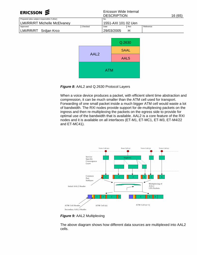
Figure 8: AAL2 and Q.2630 Protocol Layers
When a voice device produces a packet, with efficient silent time abstraction and compression, it can be much smaller than the ATM cell used for transport. Forwarding of one small packet inside a much bigger ATM cell would waste a lot of bandwidth. The RXI nodes provide support for de-multiplexing packets on the ingress and then re-multiplexing the packets on the egress side to provide for optimal use of the bandwidth that is available. AAL2 is a core feature of the RXI nodes and it is available on all interfaces (ET-M1, ET-MC1, ET-M3, ET-M4/22 and ET-MC41).
Segment
1 2 3 4 5 6
Voice Call (w) Data Call (x) Voice Call (y) Voice Call (z)
ServiceSpecificConvergenceLayer
CommonPartSublayer
Multiplexing ofAAL2CPS Packets
ATM Cell Header ATM Cell (n) ATM Cell (n+1)
1 5 2 3 3 6 4
Secondary AAL2 Header
Initial AAL2 Header
Figure 9: AAL2 Multiplexing
The above diagram shows how different data sources are multiplexed into AAL2 cells.
ATM
AAL2AAL5
SAAL
Q.2630

Ericsson Wide Internal
DESCRIPTION 17 (65)Prepared (also subject responsible if other) No.
LMI/RR/RT Michelle McElvaney 1551-AXI 101 02 Uen Approved Checked Date Rev Reference
LMI/RR/RT Srdjan Krco 29/03/2005 H
In the SSCL the data is divided into suitable sized chunks. In the CPS each of these chunks is labelled with the initial AAL2 header. This identifies the data source using the CID. These are then packed into ATM cells with a secondary AAL2 header.
AAL2 introduces a minicell concept, where several AAL2 minicells can be multiplexed into one ATM cell. As opposed to ATM cells the AAL type 2 cells are of variable length. The payload length can vary between 1 and 45 (optionally 64) octets. The AAL2 cells can thus be longer than an ATM cell and can cross ATM cell borders.
RXI 820
ET
ETET
Cell Header 5 bytes
Offset Flag 1 byte
Packet Header 3 bytes
Voice/Data PacketVariable size
Empty Cell space(ATM payload size 48 bytes)
AAL2 PVC from RBS #1
AAL2 PVC from RBS #2
Packet Switching with AAL2USwitch Core cell format
AAL2 PVC to RNC
Figure 10: Multiplexing of packets on an AAL2 ATM PVC
The above diagram shows how AAL2 data streams from 2 RBS are combined in the RXI and then transported towards the RNC.
The AAL2 minicells are first of all extracted from each incoming cell. These minicells are each put in an ATM cells of its own and transported internally. These are extracted and repacked on the egress.

Ericsson Wide Internal
DESCRIPTION 18 (65)Prepared (also subject responsible if other) No.
LMI/RR/RT Michelle McElvaney 1551-AXI 101 02 Uen Approved Checked Date Rev Reference
LMI/RR/RT Srdjan Krco 29/03/2005 H
3.6.1 ITU-T Q2630.1 and Q2630.2 Signaling Protocols
Q2630.2 is an expansion of the Q2630.1 capability set and includes the following capabilities,
• QoS Indication • Additional SSI messages • AAL2 Path Re-direction • AAL2 Path Modification • Ability to Pass-on unrecognized messages
The ITU-T Q2630.2 signaling protocol stack is backward compatible with all devices using the Q2630.1 protocol stack.
All exclusive Q2630.2 messages originated from a Q2630.2 capable signaling that terminate on a Q2630.1 signalling endpoint will be discarded. For full Q2630.2 functionality both endpoints must support Q2630.2 signalling. All other messages that are common are of the same format will be executed in the same way for both Q2630.1 and Q2630.2. For more information see Ref. [22].
3.7 AAL5 functionality
The RXI nodes provide support for AAL5 connections. AAL5 connections are provided as PVCs. AAL5 is used in the network for the following purposes: • Transport of Operation and Maintenance packets (IP packets) over AAL5 • Transport of Q.2630.2 signalling • Transport of Node B application part signalling (NBAP-C and NBAP-D), this is
transparent to the RXI 820. Q.2630.2 is carried over AAL5 and is used to dynamically establish AAL2 connections.
3.7.1 Movable CEP
Movable CEP allows the allocation of ATM VCC connection end points (CEP) to an MP to be controlled by the user of each connection, for example NBAP or NodeSynch, instead of being fixed by configuration management. Movable CEPs allows the Connection End Point (CEP) to be moved on demand from the user of the CEP. Movable CEPs for AAL5 and SAAL is supported on the MP.
Ericsson Wide Internal
DESCRIPTION 19 (65)Prepared (also subject responsible if other) No.
LMI/RR/RT Michelle McElvaney 1551-AXI 101 02 Uen Approved Checked Date Rev Reference
LMI/RR/RT Srdjan Krco 29/03/2005 H
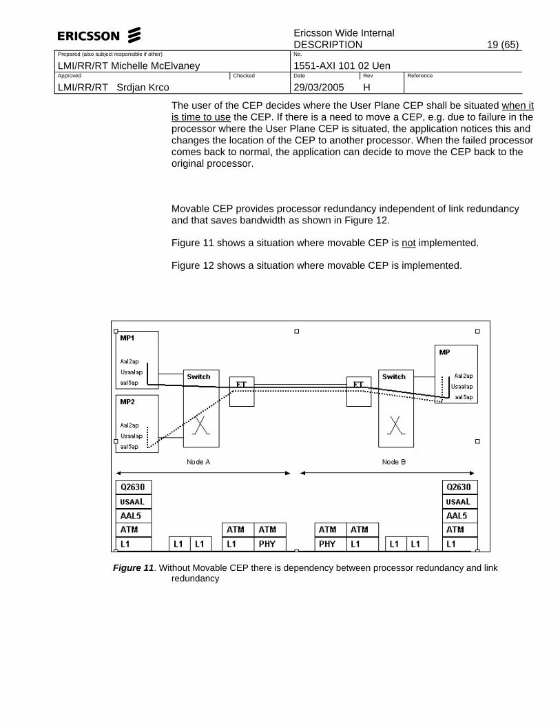
The user of the CEP decides where the User Plane CEP shall be situated when it is time to use the CEP. If there is a need to move a CEP, e.g. due to failure in the processor where the User Plane CEP is situated, the application notices this and changes the location of the CEP to another processor. When the failed processor comes back to normal, the application can decide to move the CEP back to the original processor.
Movable CEP provides processor redundancy independent of link redundancy and that saves bandwidth as shown in Figure 12.
Figure 11 shows a situation where movable CEP is not implemented.
Figure 12 shows a situation where movable CEP is implemented.
Figure 11. Without Movable CEP there is dependency between processor redundancy and link redundancy
Ericsson Wide Internal
DESCRIPTION 20 (65)Prepared (also subject responsible if other) No.
LMI/RR/RT Michelle McElvaney 1551-AXI 101 02 Uen Approved Checked Date Rev Reference
LMI/RR/RT Srdjan Krco 29/03/2005 H
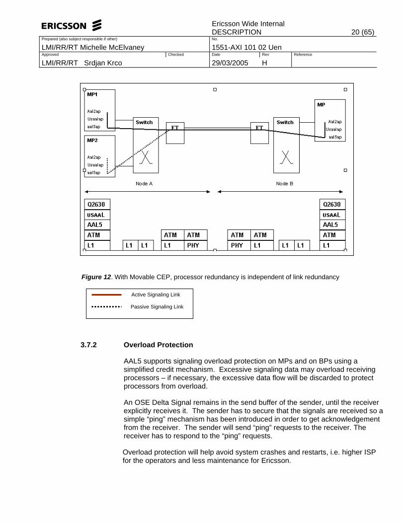
Figure 12. With Movable CEP, processor redundancy is independent of link redundancy
3.7.2 Overload Protection
AAL5 supports signaling overload protection on MPs and on BPs using a simplified credit mechanism. Excessive signaling data may overload receiving processors – if necessary, the excessive data flow will be discarded to protect processors from overload.
An OSE Delta Signal remains in the send buffer of the sender, until the receiver explicitly receives it. The sender has to secure that the signals are received so a simple “ping” mechanism has been introduced in order to get acknowledgement from the receiver. The sender will send “ping” requests to the receiver. The receiver has to respond to the “ping” requests.
Overload protection will help avoid system crashes and restarts, i.e. higher ISP for the operators and less maintenance for Ericsson.
Active Signaling Link Passive Signaling Link

Ericsson Wide Internal
DESCRIPTION 21 (65)Prepared (also subject responsible if other) No.
LMI/RR/RT Michelle McElvaney 1551-AXI 101 02 Uen Approved Checked Date Rev Reference
LMI/RR/RT Srdjan Krco 29/03/2005 H
3.8 AAL0 functionality
Internally in the RXI nodes an AAL0 stream is generated and used for synchronization within the node. AAL0 messages are generated by the TUB and sent to the other boards within the node.
As it is a node in the transport network, the RXI nodes also transport AAL0, which is used for radio bearer synchronization information from the RNC towards the RBS. The distribution of node synchronization using AAL0 is Ericsson proprietary, however AAL0 is a part of the ATM standard. This transport of AAL0 by the RXI nodes is separate to the internally generated AAL0.
3.9 IMA
IMA is a methodology that provides a modular bandwidth, for user access to ATM networks and for connection between ATM network elements, at rates between the traditional order multiplex levels. An example is to achieve rates between the DS1/E1 and DS3/E3 levels in the asynchronous digital hierarchies. DS3/E3 physical links are not necessarily readily available throughout a given network. Therefore the introduction of ATM Inverse Multiplexers provides an effective method of combining the transport bandwidths of multiple links (e.g., DS1/E1 links) grouped to collectively provide higher intermediate rates.
The ATM Inverse Multiplexing technique involves inverse multiplexing and demultiplexing of ATM cells in a cyclical fashion among links grouped to form a higher bandwidth logical link whose rate is approximately the sum of the link rates. This is referred to as an IMA group. Figure 13 provides a simple illustration of the ATM Inverse multiplexing technique in one direction. The same technique applies in the opposite direction.
ÌMA Virtual Link
Tx direction: cells distributed across links in round robin sequence Rx direction: cells recombined into single ATM stream
Rebuilt ATM Cell Stream going to ATM Layer
Single ATM Cell Stream from ATM Layer
IMA Group IMA Group PHY PHY PHY
PHY PHY PHY
Physical Link #0
Physical Link #1
Physical Link #2

Ericsson Wide Internal
DESCRIPTION 22 (65)Prepared (also subject responsible if other) No.
LMI/RR/RT Michelle McElvaney 1551-AXI 101 02 Uen Approved Checked Date Rev Reference
LMI/RR/RT Srdjan Krco 29/03/2005 H
Figure 13: Inverse Multiplexing and De-multiplexing of ATM Cells via IMA
Groups
IMA groups terminate at each end of the IMA virtual link. In the transmit direction, the ATM cell stream received from the ATM layer is distributed on a cell by cell basis, across the multiple links within the IMA group. At the far-end, the receiving IMA unit recombines the cells from each link, on a cell by cell basis, recreating the original ATM cell stream. The aggregate cell stream is then passed to the ATM layer.
The IMA interface periodically transmits special cells that contain information that permit reconstruction of the ATM cell stream at the receiving end of the IMA virtual link. The receiver end reconstructs the ATM cell stream after accounting for the link differential delays, smoothing CDV introduced by the control cells, etc. These cells, defined as IMA Control Protocol (ICP) cells, provide the definition of an IMA frame. The transmitter must align the transmission of IMA frames on all links (shown in Figure 13). This allows the receiver to adjust for differential link delays among the constituent physical links. Based on this required behavior, the receiver can detect the differential delays by measuring the arrival times of the IMA frames on each link. At the transmitting end, the cells are transmitted continuously. If there are no ATM layer cells to be sent between ICP cells within an IMA frame, then the IMA transmitter sends filler cells to maintain a continuous stream of cells at the physical layer. The insertion of Filler cells provides cell rate decoupling at the IMA sublayer. The IMA receiver should discard the Filler cells. A new OAM cell is defined for use by the IMA protocol. This cell has codes that define it as an ICP or Filler cell.

Ericsson Wide Internal
DESCRIPTION 23 (65)Prepared (also subject responsible if other) No.
LMI/RR/RT Michelle McElvaney 1551-AXI 101 02 Uen Approved Checked Date Rev Reference
LMI/RR/RT Srdjan Krco 29/03/2005 H
Figure 14: Illustration of IMA Frames
ET-MC1 and ET-MC41 board supports IMA. For more information see Ref. [17].
3.10 GPS as a Synchronization Reference GPS Synchronisation is a site solution to provide a synchronization reference when such a reference is not guaranteed via the transmission network, or where the transport network synchronization quality requirements are not fulfilled by the connected transmission links. Ring structures via unprotected dark fibre or MicroWave is one example where the GPS synchronization of all nodes in the ring is a solution. The integrated GPS antenna/receiver unit receives a timing signal from the GPS satellites. A one-pulse per second signal synchronized to the GPS system is automatically provided when the GPS receiver is locked to the GPS Satellites. The timing signal is then distributed to the master RBS through the GPS over voltage protection (OVP) box. The GPS Synchronization Solution consists of:
• GPS Antenna / Receiver Unit
ATM Layer Cell Filter CellICP Cell in Frame #1
Time
Link 0
Link 1
Link 2
M-1 2 3 M-1 0 1
… ……
… ……
… …… ATM ATMATM ATM ATMATM F F F F F F ICP2 ICP1 ICP0
ATMATM ATM ATM ATMATM F F F F ATM F ICP2 ICP1 ICP0
ATMATMATM ATM ATM ATM F F F ATM F ATMICP2 ICP1 ICP0
M-1 2 3 0 1 2 3 0 1
IMA Frame 2 IMA Frame 1 IMA Frame 0
F ICP1 ATM

Ericsson Wide Internal
DESCRIPTION 24 (65)Prepared (also subject responsible if other) No.
LMI/RR/RT Michelle McElvaney 1551-AXI 101 02 Uen Approved Checked Date Rev Reference
LMI/RR/RT Srdjan Krco 29/03/2005 H
• Overvoltage Protection • GPS Distibution unit • Cable Kits This is deployed in redundant configuration so twice the above amount of components are used. The OVP is recommended to be installed as the cable from the antenna outside comes inside the building. It is recommended the optional extra OVP’s be installed close to the node.
Figure 15: Cello Synchronization model
3.11 Mub Routing
In RAN P3 Mub routing was done in an external IP router and cross-connected over RNC and RXI820 (see figure 16). IP routing functionality for the Mub traffic is supported in the RXI 820 R5 and RXI 860 (RAN P5) with limited capability. In figure 17 Mub traffic is routed in RXI820, could be cross-connect in the RNC toward O&M router, or directly connected to the O&M router. Static routing is used in the RXI nodes. Restriction of connectivity based on source address is not supported in the RXI nodes in P5. This means that RBS-RBS connectivity is not blocked within an RNS.
RXI
2x 1pps signal supplied to the TUB2 cards
External 48V power
2 x Power and distribution unit
Optional extra: 2 * OVP in one metal box
2 * OVP in one metal box

Ericsson Wide Internal
DESCRIPTION 25 (65)Prepared (also subject responsible if other) No.
LMI/RR/RT Michelle McElvaney 1551-AXI 101 02 Uen Approved Checked Date Rev Reference
LMI/RR/RT Srdjan Krco 29/03/2005 H
The IP over ATM links provide transport of (Mub) IP packets over ATM connections. Two IP over ATM link is used per RBS for redundancy reason. At the creation of an IP over ATM link the RXI820 router automatically creates an interface route, which points to the subnet of the IP over ATM link. The route entry pointing to the site LAN of the RBS must be manually created. This route entry holds the destination Address (subnet address of the RBS site LAN), subnet mask of the RBS site LAN, next hop address (the IP address of the remote (RBS) side of IP over ATM link), routing Metric (the routing cost).
Inter-Processor Communication
The communication link between two MPs (IPC) can handle a limited number of packets per second. A high load on the IPC may result in the node crashing.
There are redundant links towards the RNC. This will avoid using the IPC and therefore avoid IPC overload.
It is recommended to configure Mub routing on the core MP. For more information on Mub routing see [18].

Ericsson Wide Internal
DESCRIPTION 26 (65)Prepared (also subject responsible if other) No.
LMI/RR/RT Michelle McElvaney 1551-AXI 101 02 Uen Approved Checked Date Rev Reference
LMI/RR/RT Srdjan Krco 29/03/2005 H
Figure 16: Mub Routing in RNS - Mub is cross-connected over RNC and RXI
RNC
RXI
RXI
RBS RBS
R
O&M router XC
R
RBS RBS
Figure 17: Mub Routing in RNS – Mub is routed in RXI

Ericsson Wide Internal
DESCRIPTION 27 (65)Prepared (also subject responsible if other) No.
LMI/RR/RT Michelle McElvaney 1551-AXI 101 02 Uen Approved Checked Date Rev Reference
LMI/RR/RT Srdjan Krco 29/03/2005 H
3.12 HSDPA
High Speed Downlink Packet Access (HSDPA) allows higher data rates to be achieved (up to 4.32Mbps) for packet data on the downlink. Three different AAL2 bearers, carrying DCCH, DTCH on DCH, and DTCH on HS-DSCH, will enable the HSDPA transmissions. DTCH on DCH, and DTCH on HS-DSCH will be carried over a class-C QoS AAL2 connection.
HSDPA AAL2 QoS Class C traffic can be carried on CBR, UBR+ or UBR AAL2 paths.
The RXI nodes are affected by the need to adapt configuration of AAL2 path terminations in order to enable AAL2 QoS Class C to be supported (see section 2.2 in [19]).
4 Role in the Network
4.1 Radio Access Network Aggregator
Radio Access Network Aggregator (RANAG) is a transport network node that may be used as ATM VP/VC cross connect or AAL2 switch.
The RANAG is a pure Transport Network Node, i.e. no Radio Network Layer functions are allocated to this node.
The RXI nodes have been designed to provide ATM aggregation capabilities within the URAN network and as such, carry out the role of a RANAG.
The reason for employing a RANAG is to achieve better utilization of the ATM VP links. There may also be savings on physical interfaces at the RNC and/or AAL2 switching resources.
The RANAG aggregates all transport connections for a number of RBS nodes onto a common/multiple VPs between the RANAG and the RNC.
The RXI nodes use AAL2 switching and/or cross connects to perform this aggregation.

Ericsson Wide Internal
DESCRIPTION 28 (65)Prepared (also subject responsible if other) No.
LMI/RR/RT Michelle McElvaney 1551-AXI 101 02 Uen Approved Checked Date Rev Reference
LMI/RR/RT Srdjan Krco 29/03/2005 H
ET-M4
1xSTM1
ET- M1
ET- M4
1xE1ET-M1
32xE1
PDH/SDHnetwork
ET-M1 1xE1
32x RBS
Figure 18: RXI 820 operating as a RANAG
The location of the RXI nodes in the network can either be co-located with the RNC or as hub in the RAN.
Further information on the WCDMA RAN Transport Network can be found in Reference [13].
5 Hardware
The new ET Hardware independent MOM will allow the following boards to be upgraded without affecting traffic – eg. ET-M1 -> ET-MC1 and ET-M4 -> ET-M4/22. It will allow the use of a new board type as a replacement or spare part for an old board type into an older CPP release without affecting its MOM and without having to make a complete re-configuration at the time of replacement.

Ericsson Wide Internal
DESCRIPTION 29 (65)Prepared (also subject responsible if other) No.
LMI/RR/RT Michelle McElvaney 1551-AXI 101 02 Uen Approved Checked Date Rev Reference
LMI/RR/RT Srdjan Krco 29/03/2005 H
The following figure shows what the new MOM looks like.
Figure 19. Generic ET MOM
5.1 RXI 820 Hardware
The RXI 820 hardware is based on hardware from the Cello Packet Platform. The following types of boards are used in the RXI 820 configuration:
• General Processor Board, GPB5x
• Switch Core Board, SCB3
• Time Unit Board, TU2
• ET-MC1 Interface Board (E1/J1/T1 Interface)
• ET-M3 Interface (E3 34Mb/s and DS3 45Mb/s Interface)
• ET-M4/22 Interface Board (STM-1 Interface)
• ET-MC41 Interface Board (Channelised STM-1 Interface for E1, J1 and T1 Interface).
<<MOClass>>PlugInUnit
<<MOClass>> ExchangeTerminal
<<MOClass>> E1PhyPathTerm
<<MOClass>> T1PhyPathTerm
<<MOClass>> J1PhyPathTerm
<<MOClass>> E3PhyPathTerm
<<MOClass>> T3PhyPathTerm
<<MOClass>> Os155SpiTtp

Ericsson Wide Internal
DESCRIPTION 30 (65)Prepared (also subject responsible if other) No.
LMI/RR/RT Michelle McElvaney 1551-AXI 101 02 Uen Approved Checked Date Rev Reference
LMI/RR/RT Srdjan Krco 29/03/2005 H
The Cello platform provides redundancy for switching, power supply and synchronization functions. In a basic configuration only one GPB, SCB, and TUB is used. If redundancy is required these boards will be duplicated.
Figure 20: RXI 820 Hardware
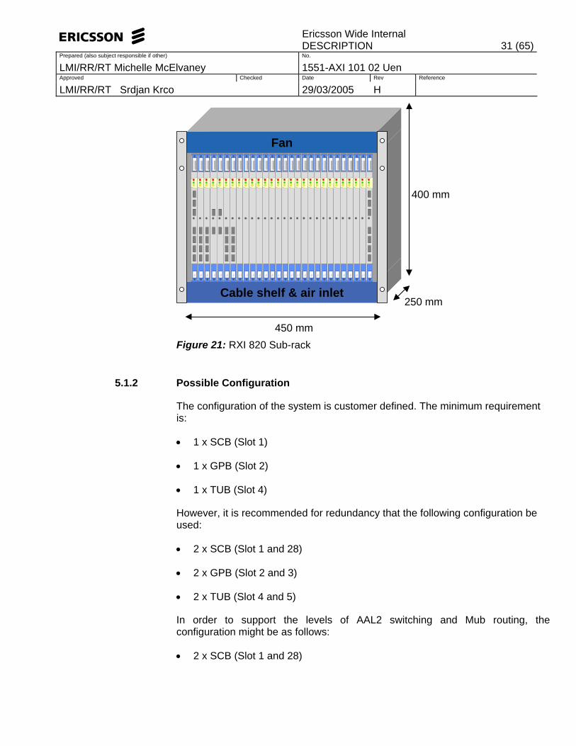
5.1.1 Subrack The RXI 820 subrack consists of 28 slots for the different plug-in units. In a fully redundant configuration (2 x GPB, 2 x SCB and 2 x TUB) 20 slots can be used for interface boards. ET-MC1, ET-M4/22 and ET-MC41 (Channelised STM-1) Interface boards are the four types of interface boards that can be used in the RXI 820. The ET-MC1 and ET-M4/22 boards require 1 slot, and the ET-MC41 board requires 2 slots. The subrack is designed to fit in the Ericsson BYB501 and BYB502 cabinets. It also fits in a standard industry 19” rack. Forced air-cooling is required and provided by a low height fan subrack mounted above the main sub-rack holding the plug-in units, making the total height 400mm.
Back Plane
GPB5x
SCB3
TU2
ET-M3
ET-MC41
ET-MC1
ET-M4/22
Ericsson Wide Internal
DESCRIPTION 31 (65)Prepared (also subject responsible if other) No.
LMI/RR/RT Michelle McElvaney 1551-AXI 101 02 Uen Approved Checked Date Rev Reference
LMI/RR/RT Srdjan Krco 29/03/2005 H
450 mm
400 mm
250 mmCable shelf & air inlet
Fan
Figure 21: RXI 820 Sub-rack
5.1.2 Possible Configuration
The configuration of the system is customer defined. The minimum requirement is:
• 1 x SCB (Slot 1)
• 1 x GPB (Slot 2)
• 1 x TUB (Slot 4)
However, it is recommended for redundancy that the following configuration be used:
• 2 x SCB (Slot 1 and 28)
• 2 x GPB (Slot 2 and 3)
• 2 x TUB (Slot 4 and 5)
In order to support the levels of AAL2 switching and Mub routing, the configuration might be as follows:
• 2 x SCB (Slot 1 and 28)

Ericsson Wide Internal
DESCRIPTION 32 (65)Prepared (also subject responsible if other) No.
LMI/RR/RT Michelle McElvaney 1551-AXI 101 02 Uen Approved Checked Date Rev Reference
LMI/RR/RT Srdjan Krco 29/03/2005 H
• 2 + 1 GPB (Slot 2, 3 and 6)
• 2 x TUB (Slot 4 and 5)
In order to support the higher AAL2 capacity and Mub routing, the configuration might be as follows:
• 2 x SCB (Slot 1 and 28)
• 3 + 1 GPB (Slot 2, 3, 6 and 7)
• 2 x TUB (Slot 4 and 5)
In 2+1 and 3+1 node configuration full redundancy is recommended.
Further information on the configuration of the Interface Boards for the RXI 820 node required to support various network scenarios, can be found in Reference 21. The next figure depicts the HW configuration options.
1 2 3 4 5 6 7 8 9 10 11 12 13 14 15 16 17 18 19 20 21 22 23 24 25 26 27 28
SCB
GPB
GPB (optional)
TUB
TUB (optional)
GPB (optional)
GPB (optional)
SCB (optional)
20 slots for interface boards
Figure 22: HW Configuration Options

Ericsson Wide Internal
DESCRIPTION 33 (65)Prepared (also subject responsible if other) No.
LMI/RR/RT Michelle McElvaney 1551-AXI 101 02 Uen Approved Checked Date Rev Reference
LMI/RR/RT Srdjan Krco 29/03/2005 H
5.2 RXI 860 Hardware
The RXI 860 hardware is based on hardware from the Cello Packet Platform. The configuration will consist of one Main subrack and 2 Extension subracks. The following type of boards are used in the RXI 860 configuration:
• GPB5x
• SCB3
• TU2
• SXB3
• ET-MC41
• ET-M4/22
• ET-MC1
• ET-M3
5.2.1 Subrack
The RXI 860 configuration consists of one Main Subrack and 2 Extension Subracks. The Extension Subracks are interconnected to the Main Subrack via Inter Subrack Links (ISLs). These ISLs are found on the SCB3 and SXB3 boards.
5.2.1.1 Main Subrack
The Main Subrack distributes the traffic to the appropriate Extension Subrack through ISLs. The functions of the Main Subrack include all those of the Extension Subrack (Section 5.2.1.2) as well as the following:
• Termination of Iub, Mub and Mut interfaces towards the RNC node via STM-1 Transmission Interface.
• Duplicated Control and Data ISL Interface to interconnect with all Extension Subracks
• Node Synchronization
• File System and Configuration Database
Early Delivery (CPP 5.0)
Main Delivery (CPP5.1)

Ericsson Wide Internal
DESCRIPTION 34 (65)Prepared (also subject responsible if other) No.
LMI/RR/RT Michelle McElvaney 1551-AXI 101 02 Uen Approved Checked Date Rev Reference
LMI/RR/RT Srdjan Krco 29/03/2005 H
• Element Manager & O&M Handling
5.2.1.2 Extension Subrack
There are 2 Extension Subracks in the RXI 860 configuration. They terminate ATM Interfaces towards RBS nodes. Its functions are:
• Termination of Iub interfaces towards the RBS nodes via Channelised STM-1.
• Duplicated Control and Data ISL Interface to interconnect with all Extension Subracks
• Part of AAL2 Switching computation resource
5.2.1.3 ISL Links Configuration
There are 4 ISL links on the SCB3 board and 4 on the SXB3 board. Each ISL link has a bandwidth of 310Mbps. There are a number of ISL Link configuration scenarios that are explained in full detail in Ref [30]. The following figure shows the hardware redundant configuration of 2 ISL Links per Main-Extension Subrack giving approximately 620Mbps Bandwidth.
5.2.2 Configuration
The MP Cluster starts with 1+1 MP redundant configuration and can be built up towards 4+1 MP Cluster. The MPs are located on the Main Subrack only in Slots 7, 8, 9, 10 and 11 – see the following figure.

Ericsson Wide Internal
DESCRIPTION 35 (65)Prepared (also subject responsible if other) No.
LMI/RR/RT Michelle McElvaney 1551-AXI 101 02 Uen Approved Checked Date Rev Reference
LMI/RR/RT Srdjan Krco 29/03/2005 H
Figure x. RXI860 Hybrid Configuration
Figure 23. RXI 860 subrack configuration
Note that the red links are the control links and the blue links represent application links.
SC
B
01
SXB
02
SXB
03 04
05
06
07
08 09
10
11
12
13
14
15
16
17
18
19
20
21
22
23
24
25 26
SX
B
27 00
SX
B
SC
B
ET-
M4/
22-2
2/E
T-M
F4E
T-M
4/22
-22/
ET-
MF4
SC
B
01
SXB
02
SXB
03 04 05 06 07 08 09
10
11 12
13 14 15 16 17 18 19 20 21 22 23 24 25 26
SX
B
27 00
SX
B
SC
B
ET-
M4/
22-2
2/E
T-M
F4E
T-M
4/22
-22/
ET-
MF4
SC
B
01
SXB
02
SXB
03
TUB
04
TUB
05
06
GPB
5
07
08 09
GP
B5/
ET-
M3
GP
B5/
ET-
M3
10
GP
B5/
ET-
M3
11
12
13
14
15
16
17
18
19
20
21
22
24
25 26
SX
B
27 00
SX
B
GPB
5
APN
SC
B
ET-
M4/
22-2
2/E
T-M
F4E
T-M
4/22
-22/
ET-
MF4
E
T-M
C41
ISL Port 4ISL Port 3ISL Port 2ISL Port 1
23
Main Subrack, SMN=0
Extension Subrack, SMN=2
Extension Subrack, SMN=1
SXB
SXB
ET-
MC
41
ET-
MC
41
ET-
MC
41
ET-
MC
41
ET-
MC
41
ET-
MC
41
ET-
MC
41
ET-
MC
41
ET-
MC
41
ET-
MC
41
ET-
MC
41
ET-
MC
41
ET-
MC
41
ET-
MC
41
ET-
MC
41
ET-
MC
41
ET-
MC
41
ET-
MC
41
ET-
MC
41
ET-
MC
41
ET-
MC
41
ET-
MC
41
ET-
MC
41
ET-
MC
41
ET-
MC
41
ET-
MC
41
ET-
MC
41
ET-
MC
41
ET-
MC
41
ET-
MC
41
ET-
MC
41

Ericsson Wide Internal
DESCRIPTION 36 (65)Prepared (also subject responsible if other) No.
LMI/RR/RT Michelle McElvaney 1551-AXI 101 02 Uen Approved Checked Date Rev Reference
LMI/RR/RT Srdjan Krco 29/03/2005 H
5.3 Boards
The following is a brief description of the boards used in the RXI nodes, more information can be found in References
The boards are hot swappable. Each board front is equipped with LEDs that provides an indication regarding the operating status of the board. There are three different LEDs at the front panel of each board. The behaviour and information provided by the LEDs are described below:
• Fault (red) • Operation (green) • Information (yellow)
The red LED has the following behaviour model:
Red LED behaviour Operation State
Steady Light Fault Out No fault.
The green LED has the following behaviour model:
Green LED behaviour Operation State
Flickering Initial boot test Fast blink Load/Test in progress Slow blink Some external resource needed to start operation Steady Light In operation Out No power.
The yellow LED has the following behaviour for all boards except the Timing Unit Board (TUB).
Yellow LED behaviour Operation State
Flickering In traffic (see Note) Slow blink Soft blocked with traffic remaining Steady Light De-blocked Out Blocked.
Note: The term “In traffic” means that this unit is carrying payload end-user traffic or performs functions necessary to maintain such traffic.
The yellow LED has the following behaviour on the Timing Unit Board (TUB):
Yellow LED behaviour Operation State
Flickering Synchronised to external source Slow blink Hold over mode

Ericsson Wide Internal
DESCRIPTION 37 (65)Prepared (also subject responsible if other) No.
LMI/RR/RT Michelle McElvaney 1551-AXI 101 02 Uen Approved Checked Date Rev Reference
LMI/RR/RT Srdjan Krco 29/03/2005 H
Steady Light De-blocked Out Blocked.
5.3.1 Switch Core Board, SCB
The SCB is a board that provides the ATM switch core in the RXI 820. It also provides other associated functions that are provided to support the board and other parts of the node and network. The SCB board [6] introduced in cello 4 provides these services and functions:
• ATM switch core • Circuits for distribution of system clock (19.44 MHz) • Fan power and control • -48V DC power connectors, filtering, supervision and distribution.
The RXI820 must be equipped with at least one SCB. It is however recommended for redundancy that the RXI 820 is equipped with two SCBs.
The ATM switch core on the SCB2 is a 16 Gbps (approximately) non-blocking cell switch. This means that the SCB2 has the capability to provide this switch capacity.
Fault LEDOperational LEDInformation LED
ISL Connectors
ISL LEDs
-48V Connector
Fan Connector
Aux Connector
Figure 24: Switch Core Board SCB

Ericsson Wide Internal
DESCRIPTION 38 (65)Prepared (also subject responsible if other) No.
LMI/RR/RT Michelle McElvaney 1551-AXI 101 02 Uen Approved Checked Date Rev Reference
LMI/RR/RT Srdjan Krco 29/03/2005 H
SCB3 [23] is a new board in R4.1, which should be used when there is a need for 4 ISL Links. The SCB2 should be used when there is a need for less then 4 ISL Links. As there is only 1 subrack in the current release of the RXI 820, the ISL (Inter Subrack Link) connectors and associated LEDs are not used.
5.3.2 General Processor Board, GPB
The GPB carries the PowerPC 750 GX as CPU and 1 GB RAM. It includes the Communication Processor PQII version HIP7. HIP7 has support for 64 SS7 channels (HIP4 supports only 32 SS7 channels).
This board acts as the main processor board has the following characteristics:
GPB52: 1 GB RAM, 512 MB flash, 750GX (1GHz), 2 Ethernet.
GPB53: 1 GB RAM, 1.5 GB flash, 750GX (1GHz), 2 Ethernet.
The RXI820 must be equipped with at least one GPB. It is however recommended for redundancy that the RXI 820 is equipped at least with two GPBs.
GPB53 is used for core and standby MP. For cost reason GPB52 may be used for capacity expansion.
Figure 25. General Processor Board, GPB
ISL
Ethernet
2xRS-232 Console, auxiliary Connector
Fault LEDOperational LED
Information LED

Ericsson Wide Internal
DESCRIPTION 39 (65)Prepared (also subject responsible if other) No.
LMI/RR/RT Michelle McElvaney 1551-AXI 101 02 Uen Approved Checked Date Rev Reference
LMI/RR/RT Srdjan Krco 29/03/2005 H
5.3.3 Timing Unit Board, TUB
The TUB provides the reference clock for the RXI 820. TUB [7] has the System clock oscillator (19.44 MHz), with 0.05ppm accuracy and 1h holding time. The clock is regenerating and stabilising a reference-timing signal synchronised to one of following references:
• Exchange Terminals (ET) connected to the public network • 1.544MHz / 2.048MHz /10MHz front connection reference.
There is one test output on the front panel of the TUB. The output clock is locked to the system clock on TUB. Output can be used for monitoring and testing of the system clock operation. The TUB front panel layout is shown in the following Figure.
Figure 26: Timing Unit Board TUB
5.3.4 ET-MC1 The ET-MC1 board is a multi-functional board, which handles the following:
• Physical Media Dependent Sublayer • Timing Rate Selection • Transmission Convergence Sublayer • ATM Layer Function
Fault LED
Operational LED
Information LED
Sync output signal
1.544/2.048/10.000 MHZ input signal GPS interface

Ericsson Wide Internal
DESCRIPTION 40 (65)Prepared (also subject responsible if other) No.
LMI/RR/RT Michelle McElvaney 1551-AXI 101 02 Uen Approved Checked Date Rev Reference
LMI/RR/RT Srdjan Krco 29/03/2005 H
• 2048 kHz Synchronization
The physical interface provided by the ET-MC1 can be classified as an unstructured interface. In the unstructured interface, the ATM traffic is mapped into one fixed bandwidth pipe. While the ET-M1 supported the E1 and J1 interfaces, the ET-MC1 supports the E1, J1 and T1 interfaces.
In contrast to the ET-M1 board, VP shaping was not possible; therefore, the RXI nodes were recommended to configure only one VP per E1/J1 port, causing the ATM traffic to be shaped to the physical line bandwidth. The ET-MC1 board does support VP shaping, with each port containing 2 shapers, allowing the RXI to configure 2 VPs per E1/T1/J1 port using traffic descriptors.
Another important ATM feature that the ET-MC1 supports is IMA (See section 3.9). When IMA is configured, a logical link (e.g. 6Mbits/s) can be created between two RXI nodes by grouping together a number of smaller physical links (e.g. 3 E1/T1 or J1 links).
The ET-MC1 supports AAL1 Circuit Emulation.
2M_sync / DIP 0 DIP 1
DIP 2 DIP 3
DIP 4 DIP 5
DIP 6 DIP 7
X52
X53
X54
X55
Fault: Red
Operation: Green
Information: Yellow
F
O
I
Figure 27: ET-MC1 Interface Board

Ericsson Wide Internal
DESCRIPTION 41 (65)Prepared (also subject responsible if other) No.
LMI/RR/RT Michelle McElvaney 1551-AXI 101 02 Uen Approved Checked Date Rev Reference
LMI/RR/RT Srdjan Krco 29/03/2005 H
5.3.5 ET-M3
The ET-M3 handles ATM cell transport over two PDH transmission links. The ET-M3 board also offers AAL2 functionality and ATM layer functionality such as ATM connection switching, that is, translation of the Virtual Path/Virtual Channel identifiers in the header of each ATM cell. It handles ATM cell transport over two PDH transmission links, termination of E3 (34 Mb/s) and T3 (45 Mb/s) interfaces, and ATM mapping according to G.804. ET-M3 includes 2 ATM ports with 16 VPs per port.
Fault: Red
Operation: Green
Information: Yellow
F
O
I
DIN_RX_0
DIN_RX1
Operation: Yellow
Fault: LOF//LOS
DIN_TX0
DIN_TX1
DIN Line Connectors
Figure 28: ET-M3 Interface Board

Ericsson Wide Internal
DESCRIPTION 42 (65)Prepared (also subject responsible if other) No.
LMI/RR/RT Michelle McElvaney 1551-AXI 101 02 Uen Approved Checked Date Rev Reference
LMI/RR/RT Srdjan Krco 29/03/2005 H
5.3.6 ET-MC41
The purpose of this board is to provide a Channelised STM-1 (155 Mbps) interface to the RXI820. The Channelised STM-1 interface is mainly used to connect the RXI820 towards the SDH Network. The ET-MC41 provides 1 Channelised STM-1 interface, where the channel structure can be based on E1 or T1, but currently not J1. For example an E1 structured STM-1 interface means that 63 E1 interfaces are mapped into an STM-1 optical interface using standard SDH multiplexing, similarly for a T1 structured STM-1 interface 84 T1 interfaces are mapped into an STM-1 optical interface using standard SDH multiplexing.
The major benefit of the ET-MC41 board over the ET-M1 board is the reduction in the number of boards needed for the same number of E1 ports (1 ET-MC41 board is equivalent to 8 ET-M1 boards).
The ET-MC41 board also introduces line protection by means of the Multiplex Section Protection (MSP 1+1) mechanism. MSP 1+1 essentially offers redundancy for the ET-MC41 boards. MSP 1+1 is also used for self-repair, that is automatic turn over to a stand-by ET-MC41 at hardware failure. MSP 1+1 requires two fibres from the SDH equipment to the RXI 820, which are terminated on separate ET-MC41 boards that are interconnected.
The ET-MC41 is implemented on 2 boards, assembled as one unit with 1 optical S-1.1 port, and takes up 2 slots in the subrack.
The ET-MC41 board supports circuit emulation and IMA respectively.
The ET-MC41 front panel layout is shown in the following Figure.

Ericsson Wide Internal
DESCRIPTION 43 (65)Prepared (also subject responsible if other) No.
LMI/RR/RT Michelle McElvaney 1551-AXI 101 02 Uen Approved Checked Date Rev Reference
LMI/RR/RT Srdjan Krco 29/03/2005 H
Figure 29: ET-MC41 Interface Board
5.3.7 ET-M4/22
ET-M4/22 HW is backwards compatible with ET-M4/1 with the following exemptions:
• The 2 MHz synchronization output on the front of ET-M4/1 will be removed on ET-M4/22
• The Optical SC-connectors in ET-M4/1 will be changed to MU connectors in ET-M4/22. An Optical adapter cable can be used for going between the two standards. One cover “nose” will cover to ports in ET-M4/22 (One cover per port in ET-M4/1)
ET-M4/1 and /22 can be mixed in the same node without problems. The different optical connectors must however be consider.
ET-M4/22 will have higher capacity on the switch port than /1 (From 520 Mb/s to 630 Mb/s). The call set-up rate will be increased by 30% due to DBM2.
Fault LED
Operational LED
Information LED
STM-1 Link
AUG Link (MSP Interface)

Ericsson Wide Internal
DESCRIPTION 44 (65)Prepared (also subject responsible if other) No.
LMI/RR/RT Michelle McElvaney 1551-AXI 101 02 Uen Approved Checked Date Rev Reference
LMI/RR/RT Srdjan Krco 29/03/2005 H
Fault LED
Operational LED
Information LED
STM-1 Link
Figure 30. ET-M4/22 Interface Board
5.3.8 Switch Extension Board, SXB3
The function of the SXB is to provide additional connections to the Extension Subracks. Each SXB contains 4 ISL links – each with a bandwidth capacity of 310Mbps.

Ericsson Wide Internal
DESCRIPTION 45 (65)Prepared (also subject responsible if other) No.
LMI/RR/RT Michelle McElvaney 1551-AXI 101 02 Uen Approved Checked Date Rev Reference
LMI/RR/RT Srdjan Krco 29/03/2005 H
Fault LEDOperational LEDInformation LED
ISL Connectors
ISL LEDs
-48V Connector
Fan Connector
Aux Connector
Figure 31. Switch Extension Board, SXB

Ericsson Wide Internal
DESCRIPTION 46 (65)Prepared (also subject responsible if other) No.
LMI/RR/RT Michelle McElvaney 1551-AXI 101 02 Uen Approved Checked Date Rev Reference
LMI/RR/RT Srdjan Krco 29/03/2005 H
Characteristics of the Interface Boards
ET board ET-M4/22 ET-MC1 ET-MC41 ET-M3
Used slots 1 1 2 1
Ports 2 8 1 2
Channels per port 1 1 63 VC-12 / 84VC-11 1
Number of VCs per board 1 800 240 ** 1 890 ** (E1), 2520
(T1/J1) 480 (240 per
port)
VP shapers 48 2 per port 2 per channel 16 per port (see reference [24])
AAL2 muxes/board 128 16 126 *** (E1), 168
(T1/J1) 32 (16 per
port)
AAL2 connections/boar
d 31 744 3 968 31 248 ***, 41664
(T1/J1)
7936
ATM on fractional No Yes Yes No
Circuit emulation No Yes Yes No
Physical media Optical S-1.1 Twisted pair Optical S-1.1 Coax 75 ohm
Max number of terminated VPs 48 per board 2 per port 2 per channelised E1 32 per board
Max number of terminated VCs
1800 per board 240 per board 30 per channelised
E1 480 per board
AAL2 muxes can be used by other
ET-boards No No No No
Physical interface STM-1/VC-4 E1/J1/T1 STM-1/VC-12 E3 /T3
Support for quality of service
for VPs CBR CBR CBR CBR
Support for quality of service
for VCs
CBR, UBR, UBR+
CBR, UBR, UBR+ CBR, UBR, UBR+
CBR, UBR,
UBR+
**) Max. 30 VCs per port
***) The ET-MC41 only supports 2 AAL2 paths per E1 logical port; therefore, it is only possible to have 126 AAL2 paths per board in ETSI mode instead of 144. This also reduces the number of AAL2 connections per board from 35,712 to 31,248
Table 3: Physical Limitations of ET Hardware

Ericsson Wide Internal
DESCRIPTION 47 (65)Prepared (also subject responsible if other) No.
LMI/RR/RT Michelle McElvaney 1551-AXI 101 02 Uen Approved Checked Date Rev Reference
LMI/RR/RT Srdjan Krco 29/03/2005 H
6 Operation and Maintenance
The RXI Element Manager provides a graphical user interface (GUI) to the Operator for handling Operation and Maintenance of the RXI nodes. The Command Line Interface can also be used for limited Operation and Maintenance activities.
6.1 RXI Element Manager
The RXI Element Manager is built on Java technology. The Java applets that comprise the application are stored on the RXI nodes’ file system. The client, that provides a graphical user interface (GUI), is run from a standard web browser on any computer. The web browser can be either Netscape Navigator or Microsoft Internet Explorer. The web browser executes Java 2 JVM (Java Virtual Machine). The server side, that provides management services to the client, is run on the RXI nodes. It utilises Java 2 Platform and HTTP server.
6.1.1 Object Explorer
As specified in Ref [24], OE is introduced to be a part of the RXI Element Manager. The advantage of this is that OE is model driven towards the MOM. That means that OE generates a GUI from the MOMs xml file, so if the MOM changes, there will not be any update of the “Properties” and “Add” windows that is used in the Element Manager. It will be implemented for the ATM and Equipment (ET parts) manager. An example of Element Manager-OE integration is shown below:
Figure 32. EMAS-OE integration

Ericsson Wide Internal
DESCRIPTION 48 (65)Prepared (also subject responsible if other) No.
LMI/RR/RT Michelle McElvaney 1551-AXI 101 02 Uen Approved Checked Date Rev Reference
LMI/RR/RT Srdjan Krco 29/03/2005 H
6.2 Management Protocols
For the communication between the RXI Element Manager (client) and the RXI node resources (server) the following protocols are used:
IIOP / SSLIOP (Internet Inter ORB Protocol / Secure Socket Layer Inter ORB Protocol)
IIOP is a CORBA-based protocol, which is used for managing the RXI nodes. It is based on TCP/IP and allows different Object Requested Brokers (ORBs) to communicate over TCP/IP based networks. The unsecure version of the IOP protocol is called IIOP and secure version is called SSLIOP (IOP over SSL).
CPP provides a number of 3GPP compliant CORBA interfaces, which are used to manage the RXI nodes. The PM and Alarm Intergration Reference Points (IRPs) are examples of these management interfaces. The RXI element manager and OSS-RC use these IRPs to carry out O&M activities on the RXI nodes.
FTP / SFTP (File Transfer Protocol / Secure File Transfer Protocol)
These protocols are used for transferring files to and from the file system in the RXI nodes. Both client and server FTP are provided in the RXI nodes.
FTP can be used for uploading different types of information from the managed to a managing system, such as product inventory data, log files, trace files, performance management files, configuration versions etc. Downloaded file types (from managing to managed system) are, for example, upgrade packages, licence keys and security certificates.
SFTP is a secure alternative to traditional FTP. It can be used to transfer files to or from any computer that runs a SSH server.
HTTP (Hyper Text Transmission Protocol)
This protocol is based on TCP/IP and is used for the distribution of HTML (Hyper Text Mark-up Language) pages and other data, such as Java applets, from an HTTP server to Web browsers (clients) over the Internet.
HTTP Server (Web Server) is available on the RXI nodes. It enables the transfer of HTML documents from the file system of the nodes to the Web browser that is used for running the RXI Element Manager.

Ericsson Wide Internal
DESCRIPTION 49 (65)Prepared (also subject responsible if other) No.
LMI/RR/RT Michelle McElvaney 1551-AXI 101 02 Uen Approved Checked Date Rev Reference
LMI/RR/RT Srdjan Krco 29/03/2005 H
The RXI Element Manager is a Web-based application. It is started from a Web browser with enabled Java 2 JVM running on the client device. Initially, the element manager’s home page is downloaded from the RXI node’s file system. The home page is an HTML document that contains instructions for the RXI Element Manager applets to be downloaded to the client device. After they are downloaded, applets are executed by the JVM. At that stage IIOP becomes the main protocol for communication between the element manager and the node.
For some of the network element managing purposes, the following protocols can also be used:
TELNET/ssh
TELNET is a TCP/IP based application protocol that enables interaction between the terminal (client) and a program that is running in another computer (server). The RXI nodes provide a SSH (Secure SHell) type of a TELNET connection. SSH is a program that enables logging into another computer over a network to execute commands on a remote machine, and to move files from one machine to another. It provides secure communication over insecure channels.
TELNET/ssh can be used for local and remote access to the shell commands supported by the RXI nodes. Some of the shell commands are targeted towards the node’s operating system (e.g. for accessing the file system) while others are targeted towards the node’s software resources (e.g. for advanced fault analysis).
The TELNET/ssh interface is NOT intended for configuration of the system.
The connection between the RXI Element Manager and the RXI nodes can be remote using IP over ATM (in-band communication) or local using Ethernet (out-of-band communication). Applications that use IIOP, FTP, HTTP and TELNET/ssh are communicating with the RXI node resources using Ethernet or IP over ATM connection. All these connections are established over TCP/IP protocol.
The following type of connection is used mainly for debugging purposes:
Serial Connection
When there is no IP connection with the RXI nodes, a serial connection via physical RS232C (V.24/V.28) interface can be used. Commands for the RXI operating system can be accessed via a serial protocol. It provides the same command-line user interface as is available with a TELNET session. There is no functional difference between the two.

Ericsson Wide Internal
DESCRIPTION 50 (65)Prepared (also subject responsible if other) No.
LMI/RR/RT Michelle McElvaney 1551-AXI 101 02 Uen Approved Checked Date Rev Reference
LMI/RR/RT Srdjan Krco 29/03/2005 H
The client device runs a terminal emulator. Commands typed through the terminal emulator, that are sent as a bit stream to the RXI nodes, are conveyed over the serial connection to the RS232C port on the GPB. A command line interpreter (shell) that runs on the RXI nodes provides communication with the other RXI operating system resources.
Figure 33: Management Protocols

Ericsson Wide Internal
DESCRIPTION 51 (65)Prepared (also subject responsible if other) No.
LMI/RR/RT Michelle McElvaney 1551-AXI 101 02 Uen Approved Checked Date Rev Reference
LMI/RR/RT Srdjan Krco 29/03/2005 H
6.3 Management Functions
The management function in the RXI nodes supports the following functional areas:
• Fault Management
• Configuration Management
1. Equipment Management
2. ATM Management
3. IP Management
4. Software Management
5. Signalling Management
• Security Management
• Performance Management
6.3.1 Fault Management
Fault Management (FM) Support is a system function that describes the functions for handling of alarm and event notifications from Managed Objects (MOs). FM Support consists of the two sub-functions:
• Alarm/Event Service
• Alarm Manager,
And the two different interfaces:
• Alarm Generation Interface (ALI)
• Alarm Client Interface (ALCI).
The ALI is the interface through which the MOs can send alarms, change severity, and clear active alarms. The ALI can also be used to send events.
The ALCI is the interface through which an RXI Element Manager can communicate FM information, for example, subscribe to alarm and event notifications. The ALCI is an implementation of Interface Definition Language (IDL) specifications for the Alarm and Notification services, version 3.1.0, defined by 3rd Generation Partnership Project (3GPP). It is divided into the two sub-parts:
• Notification IRP

Ericsson Wide Internal
DESCRIPTION 52 (65)Prepared (also subject responsible if other) No.
LMI/RR/RT Michelle McElvaney 1551-AXI 101 02 Uen Approved Checked Date Rev Reference
LMI/RR/RT Srdjan Krco 29/03/2005 H
• Alarm IRP.
Notification IRP provides primitives for support of notifications. A user can subscribe to Notifications to be sent from FM Support. Notifications are sent when an alarm is created, changed or deleted and when the alarm is rebuilt. Notifications are also sent for new fault related events. Alarm IRP provides primitives for retrieving the active alarm list and to acknowledge alarms in the list.
The Alarm/Event Service gives MOs the possibility to send alarms and events via ALI and gives a management system (such as the RXI Element Manager) the possibility to subscribe to alarms and events or to read the active alarm list via ALCI.
The Alarm Manager function provides the means for a managing system to present and maintain the node’s alarms and events. The function is itself an element management application and as such it is used in the RXI Element Manager. The Alarm Manager function consists of the three parts:
• Active Alarm List
• Alarm Log
• Event Log.
Subscription to the Alarm/Event Service in the RXI nodes occurs automatically when the Operator enters the Alarm Manager application. The active alarms are retrieved and presented in an Alarm List GUI window. The Operator has a possibility to acknowledge and unacknowledge each alarm separately. When an alarm notification is received from the node, the Alarm List window is automatically updated.
The Alarm Manager application also retrieves the contents of the alarm log from the node, and presents it to the end-user in an Alarm Log Viewer GUI window. Each change of an alarm is logged in the alarm log. Since alarms can be in different states, there may be several log entries for each alarm.
The Alarm Manager application retrieves the contents of the event log from the node, and presents it to the end-user in an Event Log GUI window. Each event is logged in the event log.
In the Alarm Manager part of the RXI Element Manager, the alarm list can also be filtered using a specific alarm type as filtering criteria. All the alarms correspond to one of the following types:
• Communications
• Processing Error

Ericsson Wide Internal
DESCRIPTION 53 (65)Prepared (also subject responsible if other) No.
LMI/RR/RT Michelle McElvaney 1551-AXI 101 02 Uen Approved Checked Date Rev Reference
LMI/RR/RT Srdjan Krco 29/03/2005 H
• Environmental
• Quality of Service
• Equipment.
Alarm Manager provides Help-On-Alarm function.
There are a number of measures, which aim to improve the Fault Management functionality of the RXI nodes. These include:
• Subscribing to alarms with a filter
• Possible to exclude an alarm type with the filter
• Read the active alarm list with filter applied
• Change severity for an alarm type – an operator can change the Perceived Severity of an alarm type, which is persistently stored by the alarm service i.e. It survives a restart of the node.
• OPI title and specific problem are identical –no cross reference list is needed for mapping
The following figure shows an overview of the Alarm Filtering service:
Figure 34. Alarm Filtering overview

Ericsson Wide Internal
DESCRIPTION 54 (65)Prepared (also subject responsible if other) No.
LMI/RR/RT Michelle McElvaney 1551-AXI 101 02 Uen Approved Checked Date Rev Reference
LMI/RR/RT Srdjan Krco 29/03/2005 H
6.3.2 Configuration Management
The RXI nodes support the configuration and control of items such as physical interfaces, link protocols and devices. All software required for this configuration is contained on the RXI nodes.
The RXI Element Manager or Command Line Interface (using Configuration Files) enables the setting and modification of parameters associated with the RXI nodes configuration. This can be for initial configuration or due to changes in the network, such as the installation of new nodes/links.
1) Equipment Management
The RXI nodes support management of the hardware equipment. It is possible to read the hardware structure and operational status. When a new board is entered into the system it will be detected automatically and the database will be updated with information about the new hardware.
If the new item is pre-configured it will automatically be put into service after the application modules have been loaded. This also means that no manual configuration is required for hardware replacements. If the new hardware is not pre-configured then it is put into service after the Operator has performed the configuration. New boards can be added to the RXI nodes without disturbing on-going traffic. The equipment is self-identifying, including board type and revision. This makes it possible to verify board types with configuration data.
The RXI provides alarms with identification of any failed components. All equipment has the capability of self-testing.
2) ATM Management
By using the ATM Management function in the RXI nodes it is possible to manage and configure parts of the ATM transmission. Currently support is provided for the following parts:
• AAL0 Termination Point Management
• AAL2 Path Management
• AAL5 Termination Point Management
• ATM Traffic Descriptor Management
• ATM Cross Connection Management.
Using the Signalling Tool support is provided for:

Ericsson Wide Internal
DESCRIPTION 55 (65)Prepared (also subject responsible if other) No.
LMI/RR/RT Michelle McElvaney 1551-AXI 101 02 Uen Approved Checked Date Rev Reference
LMI/RR/RT Srdjan Krco 29/03/2005 H
• UNI SAAL Profile Management
• UNI SAAL Termination Point Management.
3) IP Management
The IP Manager is included as a part of the RXI nodes. It provides management facilities for the IP area.
4) Software Management
Note: The RXI 860 does not support Software Upgrade, as it is the first product.
The RXI supports both local and remote handling of software, including software installation, software upgrades (RXI 820 only) and backups. It is possible to download and remove software on the RXI 820 while in operation with minimum traffic disturbance. Changing software requires a node restart. A software backup can be performed and stored in the RXI periodically or on request. This backup can then be used as a fallback if the new software version fails. The new software is downloaded to the RXI using FTP. If a new version of software does not operate correctly, the system can be reverted to its pre-upgrade state.
The Configuration Version concept is used both for Software management and backup/restore. A Configuration Version contains all the persistently stored configuration data that the node requires to reach operational status.
Remote CV Backup and Restore
It is possible to create remote backups directly from the RXI nodes to an FTP Server and to restore the RXI nodes by a direct access to an FTP Server.
Soft Software Upgrade
When upgrading the RXI 820, the board based upgrade method can be used to minimize the traffic disturbance in the network. The individual board restarts lead to lower traffic downtime than complete node restart.
The implementation of this function is done in the Upgrade Control File (UCF) in the Upgrade Package. The operator will now be able to choose whether to carry out the SW upgrade in a “soft” (minimized traffic impact but possibly longer duration) or “hard” (by means of node restart – shorter duration) way. The method is selected with a button in the EMAS GUI.
Ericsson Wide Internal
DESCRIPTION 56 (65)Prepared (also subject responsible if other) No.
LMI/RR/RT Michelle McElvaney 1551-AXI 101 02 Uen Approved Checked Date Rev Reference
LMI/RR/RT Srdjan Krco 29/03/2005 H
Upgrade Observability
A number of enhancements have been implemented in the UpgradePackage MO to provide better observability during upgrade. Three new attributes will be added to the UpgradePackage MO, these are:
• stepLabel, shows what step of the upgrade that’s currently executing
• maxTimeBetweenUpgradeEvents, states the minimum time that is allowed to elapse before the next upgrade event shall be sent
• sentEvents, defines whether to sent upgrade events or not during upgrade
The attributes ‘progressCount’ and ‘progressTotal’ are also slightly changed.
The attribute ‘progressCount’ indicates progress during installation or execution of an upgrade package.
The attribute ‘progressTotal’ indicates the total amount of load modules to be downloaded during installation. During the upgrade execution, this attribute indicates the total number of steps in the upgrade sequence.
During execution of system upgrade, FM events will be sent to indicate the progress. There are 3 different types of events defined:
• Function oriented
• Warnings
• Results (OK/NOK)
The following figure shows an example of each of the 3 events:

Ericsson Wide Internal
DESCRIPTION 57 (65)Prepared (also subject responsible if other) No.
LMI/RR/RT Michelle McElvaney 1551-AXI 101 02 Uen Approved Checked Date Rev Reference
LMI/RR/RT Srdjan Krco 29/03/2005 H
Figure 35. System Upgrade Events
Further information on System Upgrade Support for the RXI 820 can be found in Reference [27], [28]
5) Signalling Management
The main functionality of the Signalling Manager is to provide the Operator with a tool that enables the Operator to add, delete and view properties of the AAL2 Access Point.
The Signalling Manager also provides additional functionality including the possibility to add, delete and view the properties of the following:
• AAL2 Path Distribution Unit
• AAL2 Routing Case
• UNI SAAL Termination Point

Ericsson Wide Internal
DESCRIPTION 58 (65)Prepared (also subject responsible if other) No.
LMI/RR/RT Michelle McElvaney 1551-AXI 101 02 Uen Approved Checked Date Rev Reference
LMI/RR/RT Srdjan Krco 29/03/2005 H
• UNI SAAL Profile.
6.3.3 Security Management
COLI commands will activate/deactivate CORBA security. Users can be assigned different “roles” – each role having specific COLI commands to be used for them. The different roles are:
• Field Normal
• Field Advanced
• Ericsson Specific
• Security
There will be Access Control on the Element Manager Interfaces per Function Area. The 2 levels of access are:
• Read
• Write
• No Access Control
Eg. A user with “PM Advanced” role will be allowed to list and suspend scanners.
A user with “PM Normal” role will only be allowed to list scanners.
6.3.4 Performance Management
Performance management (PM) scanners are activated on the RXI nodes to produce statistical counter information. This statistical counter information is packed into a PM ROP file and compressed at intervals of 15 minutes. OSS-RC collects these ROP files and stores them for later analysis.
The CPP PM IRP provides an interface to create, delete, list, suspend and resume scanners on the RXI node. The RXI Element Manager can list and suspend scanners and is used for troubleshooting purposes when it is not possible to connect to the RXI node remotely. OSS-RC can create, delete and resume scanners as well as listing and suspending scanners.
In P5 the counter capacity has increased from 50,000 to 65,000. This is the Cello default value.
See Ref [30] for more information on Counter Capacity Improvements in P5.

Ericsson Wide Internal
DESCRIPTION 59 (65)Prepared (also subject responsible if other) No.
LMI/RR/RT Michelle McElvaney 1551-AXI 101 02 Uen Approved Checked Date Rev Reference
LMI/RR/RT Srdjan Krco 29/03/2005 H
6.4 Configuration Files for the RXI nodes
The RXI nodes can be configured using the technique established with the introduction of the MO Tester tool. This technique introduces the Configuration File concept as a way to configure the node. Configuration files, also known as MO Scripts, are textual files that contain a set of instructions of what to do with the MO’s in a node’s MIB.
Configuration files are executed using the Configuration File Service (CFS) system function. CFS is a part of the RXI 820 Element Management functionality. CFS is equipped with the same functionality that is part of the MO Tester tool as well as a number of enhancements. Note that the MO Tester is not supported for use by end-users.
Further information on the Configuration File System can be found in Reference [11].
Managed Object (MO) is a software object that encapsulates the manageable characteristics and behaviour of a particular node component. The MO is an instance of a MO class defined in a MOM. A MO class has attributes that provide information to the used to characterise the objects that belong to the class. Furthermore, a MO class can have operations that represent the behaviour relevant for that class. A MO class may support notifications that provide information about an event occurrence within a network resource.
Managed Object Model (MOM) is a model representing the actual managed node resources that an RXI 820 system is providing through an open interface. A MOM describes Managed Object Classes, their associations, attributes and operations. The MOM is also referred to as “MIM”. There is a slight difference between the two terms – the term MIM is generic and can be used to denote any type of management model, while MOM denotes the model of the actual network element (node).
Management Information Base (MIB) is the set of existing managed objects in a managed domain, together with their attributes. MIB can be considered as an instance of MOM.
6.5 Command Line Interface, CLI
The RXI nodes also have a Command Line Interface (CLI). This shell command interface is an administrative interface that an Operator can use to configure, manage, and maintain the RXI nodes. (This interface is common to all Cello-based nodes).
The interface is provided by a set of shell commands, which are handled by a UNIX shell-like command interpreter.

Ericsson Wide Internal
DESCRIPTION 60 (65)Prepared (also subject responsible if other) No.
LMI/RR/RT Michelle McElvaney 1551-AXI 101 02 Uen Approved Checked Date Rev Reference
LMI/RR/RT Srdjan Krco 29/03/2005 H
For full details on these commands see Reference [8].
It is not recommended that the Operator use the Command Line Interface. The interface is primarily for use by Ericsson staff.
6.6 Improved Node ISP
When the RXI nodes (or individual boards) are manually restarted, the user is forced to choose a reason – there will be no default reason provided. The user input will include pre-selected and free text parts. The reason is stored in the restart and availability log.
7 Technical Specifications
The dimensions for the RXI 820 subrack are as follows:
Weight: ~30 kg fully equipped
Height: 400 mm including fan and air guide
Width: 450 mm (can be mounted in a 19” rack)
Depth: 250 mm including cable shelf.
7.1 Power
Power supply: -48V DC
Power consumption: max 800 W per subrack.

Ericsson Wide Internal
DESCRIPTION 61 (65)Prepared (also subject responsible if other) No.
LMI/RR/RT Michelle McElvaney 1551-AXI 101 02 Uen Approved Checked Date Rev Reference
LMI/RR/RT Srdjan Krco 29/03/2005 H
8 Abbreviations
AAL0 ATM Adaptation Layer 0 AAL ATM Adaptation Layer AAL1 ATM Adaptation Layer 1 AAL2 ATM Adaptation Layer 2 AAL5 ATM Adaptation Layer 5 AAL5 TP AAL5 Termination Point ABR Available Bit Rate ALCI Alarm Client Interface ALI Alarm Generation Interface ATM Asynchronous Transfer Mode AUG Administrative Unit Group AUX Auxiliary BR Burst Rate BSC Base Station Controller BTS Base Transceiver Station CBR Constant Bit Rate CDV Cell Delay Variation CDVT Cell Delay Variation Tolerance CEP Connection End Point CES Circuit Emulation Service CID Cell Identity CLI Command Line Interface CLR Cell Loss Ratio COLI Command Line Interface CORBA Common Object Request Broker Architecture CP Connection Point CPI Customer Product Information CPP Cello Packet Platform CPU Central Processing Unit CTD Cell Transfer Delay DBR Deterministic Bit Rate DCCH Dedicated Control Channel DCH Dedicated Channel DTCH Dedicated Traffic Channel HS-DSCH High Speed Downlink Shared Channel FM Fault Management

Ericsson Wide Internal
DESCRIPTION 62 (65)Prepared (also subject responsible if other) No.
LMI/RR/RT Michelle McElvaney 1551-AXI 101 02 Uen Approved Checked Date Rev Reference
LMI/RR/RT Srdjan Krco 29/03/2005 H
FPM Forward Performance Monitoring FTP File Transfer Protocol GFR Guaranteed Frame Rate GPB General Processor Board GPS Global Positioning System GSM Global System for Mobile communication GUI Graphical User Interface HSDPA High Speed Downlink Packet Access HTML Hypertext Markup Language HTTP Hyper Text Transfer Protocol HW Hard Ware IDL Interface Definition Language IIOP Internet Inter ORB Protocol IP Internet Protocol IRP Integration Reference Point ISL Inter Sub-rack Link ITU-T International Telecommunications Union -
Telecommunication LED Light Emitting Diode LTR Loss of Tracking MB Mega Byte Mbps Mega bit per second MBS Maximum Burst Size MCR Minimum Cell Rate MDCR Minimum Desired Cell Rate MHz Mega Hertz MIB Management Information Base MIM Managed Information Model MMI Machine-to-Machine Interface MO Managed Object MOM Managed Object Model MS Management Service MSP Multiplex Section Protection NBAP-C Node B Application Protocol - Common NBAP-D Node B Application Protocol – Dedicated NSS Network Synchronization System OE Object Explorer ORB Object Request Broker OSPF Open Shortest Path First

Ericsson Wide Internal
DESCRIPTION 63 (65)Prepared (also subject responsible if other) No.
LMI/RR/RT Michelle McElvaney 1551-AXI 101 02 Uen Approved Checked Date Rev Reference
LMI/RR/RT Srdjan Krco 29/03/2005 H
OVP Over Voltage Protection PCR Peak Cell Rate PDH Plesiosynchronous Digital Hierarchy PPS Pulse Per Second PRC Primary Reference Clock PVC Permanent Virtual Connection QoS Quality of Service RAM Random Access Memory RAN Radio Access Network RANAG Radio Access Network Aggregator RBS Radio Base Station RNC Radio Network Controller SAAL Signalling ATM Adaptation Layer SBR Statistical Bit Rate SCB Switch Core Board SCCP Signalling Connection Control Part SCR Sustainable Cell Rate SDH Synchronous Digital Hierarchy SFTP Secure File Transfer Protocol SS7 Signalling System No. 7 SSCL Serial SCSI Command Language SSH Secure Shell STM-1 Synchronous Transfer Mode-1 SVC Switched Virtual Connection TDM Time Division Multiplexing TUB Time Unit Board UBR Unspecified Bit Rate UMTS Universal Mobile Telecommunications System UNI User Network Interface URAN UMTS Radio Access Network URL Unified Resource Locator VBR Variable Bit Rate VC Virtual Channel VCC Virtual Channel Connection VCI Virtual Channel Identifier VCL Virtual Channel Link VP Virtual Path VPI Virtual Path Identifier XML Extensible Markup Language

Ericsson Wide Internal
DESCRIPTION 64 (65)Prepared (also subject responsible if other) No.
LMI/RR/RT Michelle McElvaney 1551-AXI 101 02 Uen Approved Checked Date Rev Reference
LMI/RR/RT Srdjan Krco 29/03/2005 H
9 References
[1] Cello System Description 1551-CSX 101 09 [2] GPB4, General Purpose Processor Board 102 62-ROJ 119 2106/4 [3] ET-M4/22, Design Specification, 102 62-ROJ 119 2102/22 [4] ET-M3, Exchange Terminal for ET/T3 102 62-ROJ 119 2214/1 [5] ET-MC1 102 62-ROJ 119 2163/1 [6] Description of SCB3 1/1551-ROJ 119 2108/4 [7] TIMING UNIT, CLOCK GENERATION PART 1/1551-ROJ 119 2104/4 [8] Command Line Interface, 1553-CXA 104 203 [9] Traffic Management, System Principles 5/1551-CSX 101 09 [10] ET-MC41 Quick Study – RXI 820 R3.1 ATM 2/0363-FCP 103 4423 [11] Configuration File Service Function Specification 1/155 17-62/CSX 101 09 [12] Product Structure RXI820ATM 1315-AXI 101 02 [13] WCDMA RAN Transport Network Application Information 5/15518-HSD
101 02/1 [14] Q 2630.2 in the RXI 820 R4 5/0363-FCP 103 4760 Uen [15] Inverse Multiplexing for ATM (IMA) 11/0363-FCP 103 4423 Uen [16] GPS as a Synchronization Reference for RXI820 17/0363-FCP 103 4423
Uen [17] Transport Services in Cello 4/1551-CSX 101 09 Uen [18] Mub Routing and AAL2 Capacity Expansion, RXI 820 R4.1, 1/15941-
FCP1035209 [19] Network Design Specification : HSDPA RAB Control Plane, 2/102 68 – FCP
103 5202 Rev. B. [20] Work package Specification for the GPB5 team, 6/12702-26/FCP1051026 [21] Product introduction Plan for ET-M4/22 in CPP-based Application, 10925-
ROJ1192102/22 [22] UTRAN Vocabulary, 1/0033-HSD 101 02/1 [23] Switch Core board, SCB3 109 21-ROJ 119 2108/4 [24] RNC Dimensioning Guideline for P3, Error! Unknown document property
name. rev E3 [25] User Guide for GUI Support Interface, 1553-CXA 104 218 Rev T [26] CPP5 Impact on O&M (MOM/CMA), 0363-25/FCP 105 1026 Rev PH2 [27] Cross Reference List, CPP Events sent at System Upgrade and MIB
Recovery Rev C, 1/001 21-25/FCP 105 1026 [28] Network Design Specification: Soft SW Upgrade, 60/10268-FCP 103 5302 [29] System Upgrade Support, 155 17-13/CSX 101 09 Uen [30] Network Design Specifiction: Counter Capacity Improvements, 50/10268-
FCP1035302 [31] RXI 860 HW & SW Dimensioning Guide, WCDMA P5, 3/0363-FCP 103 5308

Ericsson Wide Internal
DESCRIPTION 65 (65)Prepared (also subject responsible if other) No.
LMI/RR/RT Michelle McElvaney 1551-AXI 101 02 Uen Approved Checked Date Rev Reference
LMI/RR/RT Srdjan Krco 29/03/2005 H


![ENGINE STR A · 2017. 2. 25. · < SYSTEM DESCRIPTION > [VQ35DE] STARTING SYSTEM SYSTEM DESCRIPTION STARTING SYSTEM System Diagram INFOID:0000000007255932 System Description](https://img.pdfslide.net/doc/110x75/61331345dfd10f4dd73adac1/engine-str-a-2017-2-25-system-description-vq35de-starting-system.jpg)