Embed Size (px)
Citation preview
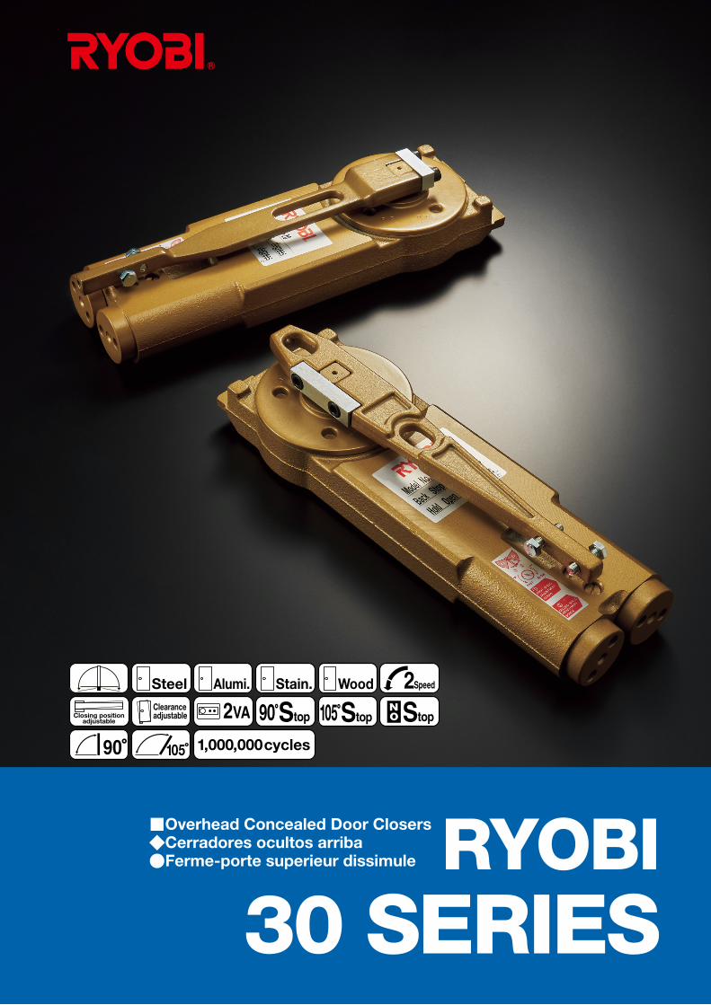
30 SERIESRYOBI
RYOBI LIMITED5-2-8 Toshima, Kita-ku Tokyo 114-8518, JapanTel. 81-3-3927-5536 Fax. 81-3-3927-5527RYOBI is a registered trade mark of Ryobi Limited
■Overhead Concealed Door Closers◆Cerradores ocultos arriba●Ferme-porte superieur dissimule
1,000,000cycles
Steel Alumi. WoodStain.
Closing positionadjustable
Clearanceadjustable 90 105
30 SERIESOverhead concealed door closer
2 3
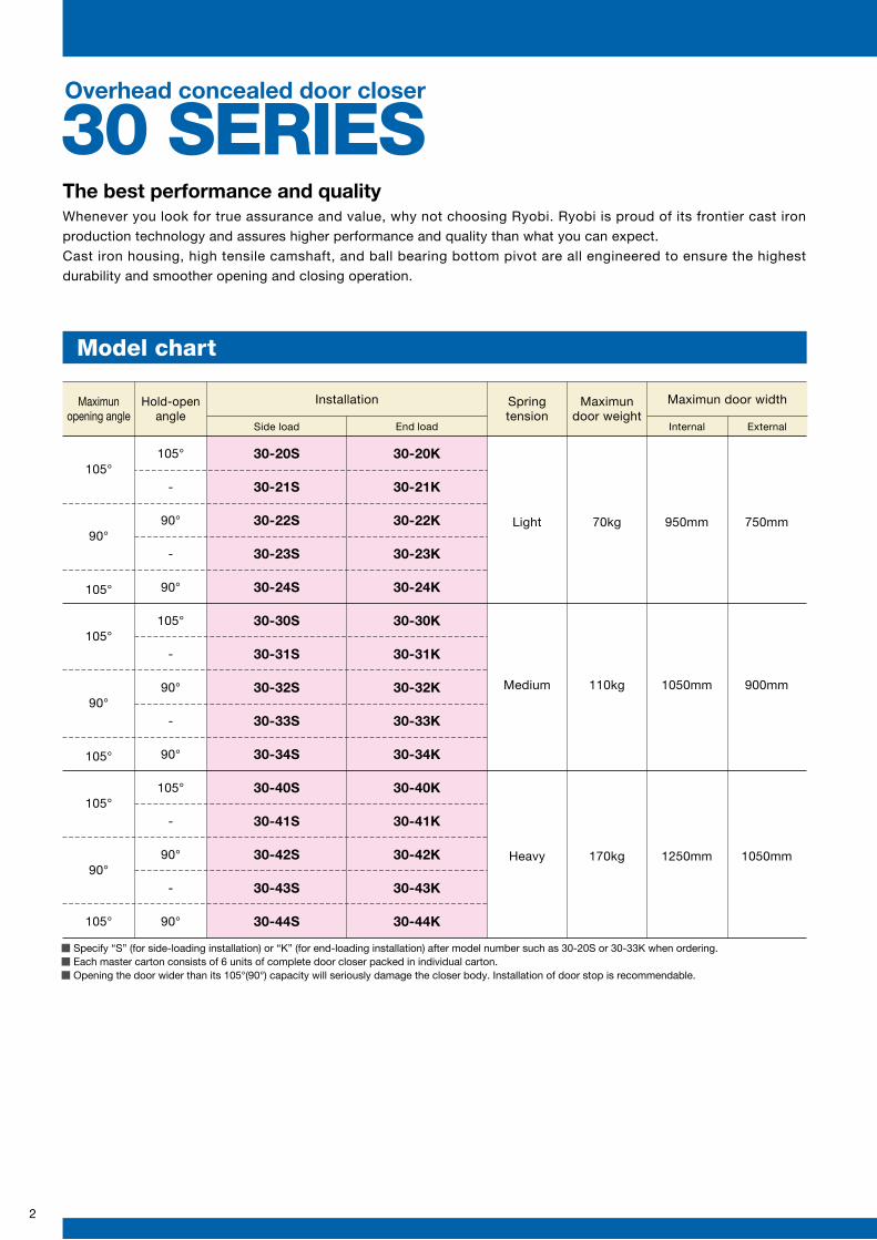
Maximunopening angle
Springtension
Maximundoor weight
Hold-openangle
Maximun door widthInstallation
Side load Internal
105°
-
90°
-
90°
105°
-
90°
-
90°
105°
-
90°
-
90°
30-20S
30-21S
30-22S
30-23S
30-24S
30-30S
30-31S
30-32S
30-33S
30-34S
30-40S
30-41S
30-42S
30-43S
30-44S
30-20K
30-21K
30-22K
30-23K
30-24K
30-30K
30-31K
30-32K
30-33K
30-34K
30-40K
30-41K
30-42K
30-43K
30-44K
105°
Light
Overhead concealed door closer 30 SERIES
Model chart
The best performance and quality
End load External
90°
105°
105°
105°
105°
90°
105°
90°
Medium
Heavy
70kg
110kg
170kg
950mm
1050mm
1250mm
750mm
900mm
1050mm
Whenever you look for true assurance and value, why not choosing Ryobi. Ryobi is proud of its frontier cast iron production technology and assures higher performance and quality than what you can expect.Cast iron housing, high tensile camshaft, and ball bearing bottom pivot are all engineered to ensure the highest durability and smoother opening and closing operation.
■ Specify “S” (for side-loading installation) or “K” (for end-loading installation) after model number such as 30-20S or 30-33K when ordering.■ Each master carton consists of 6 units of complete door closer packed in individual carton.■ Opening the door wider than its 105°(90°) capacity will seriously damage the closer body. Installation of door stop is recommendable.
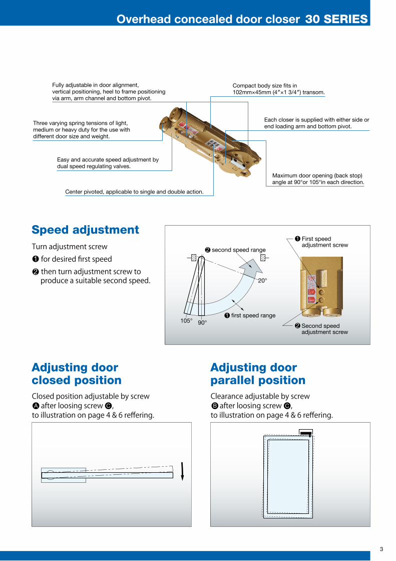
Fully adjustable in door alignment,vertical positioning, heel to frame positioningvia arm, arm channel and bottom pivot.
Compact body size fits in102mm×45mm (4″×1 3/4″) transom.
Each closer is supplied with either side orend loading arm and bottom pivot.
Maximum door opening (back stop) angle at 90°or 105°in each direction.
Three varying spring tensions of light,medium or heavy duty for the use withdifferent door size and weight.
Easy and accurate speed adjustment bydual speed regulating valves.
Center pivoted, applicable to single and double action.
Turn adjustment screw for desired first speed then turn adjustment screw to produce a suitable second speed.
Speed adjustment
Closed position adjustable by screw after loosing screw , to illustration on page 4 & 6 reffering.
Adjusting doorclosed position
1
2
1
2
First speedadjustment screw
Second speedadjustment screw
CAClearance adjustable by screw after loosing screw ,to illustration on page 4 & 6 reffering.
Adjusting doorparallel position
CB
90°first speed range
20°
105°1
second speed range2
30 SERIESOverhead concealed door closer
2 3
Maximunopening angle
Springtension
Maximundoor weight
Hold-openangle
Maximun door widthInstallation
Side load Internal
105°
-
90°
-
90°
105°
-
90°
-
90°
105°
-
90°
-
90°
30-20S
30-21S
30-22S
30-23S
30-24S
30-30S
30-31S
30-32S
30-33S
30-34S
30-40S
30-41S
30-42S
30-43S
30-44S
30-20K
30-21K
30-22K
30-23K
30-24K
30-30K
30-31K
30-32K
30-33K
30-34K
30-40K
30-41K
30-42K
30-43K
30-44K
105°
Light
Overhead concealed door closer 30 SERIES
Model chart
The best performance and quality
End load External
90°
105°
105°
105°
105°
90°
105°
90°
Medium
Heavy
70kg
110kg
170kg
950mm
1050mm
1250mm
750mm
900mm
1050mm
Whenever you look for true assurance and value, why not choosing Ryobi. Ryobi is proud of its frontier cast iron production technology and assures higher performance and quality than what you can expect.Cast iron housing, high tensile camshaft, and ball bearing bottom pivot are all engineered to ensure the highest durability and smoother opening and closing operation.
■ Specify “S” (for side-loading installation) or “K” (for end-loading installation) after model number such as 30-20S or 30-33K when ordering.■ Each master carton consists of 6 units of complete door closer packed in individual carton.■ Opening the door wider than its 105°(90°) capacity will seriously damage the closer body. Installation of door stop is recommendable.
Fully adjustable in door alignment,vertical positioning, heel to frame positioningvia arm, arm channel and bottom pivot.
Compact body size fits in102mm×45mm (4″×1 3/4″) transom.
Each closer is supplied with either side orend loading arm and bottom pivot.
Maximum door opening (back stop) angle at 90°or 105°in each direction.
Three varying spring tensions of light,medium or heavy duty for the use withdifferent door size and weight.
Easy and accurate speed adjustment bydual speed regulating valves.
Center pivoted, applicable to single and double action.
Turn adjustment screw for desired first speed then turn adjustment screw to produce a suitable second speed.
Speed adjustment
Closed position adjustable by screw after loosing screw , to illustration on page 4 & 6 reffering.
Adjusting doorclosed position
1
2
1
2
First speedadjustment screw
Second speedadjustment screw
CAClearance adjustable by screw after loosing screw ,to illustration on page 4 & 6 reffering.
Adjusting doorparallel position
CB
90°first speed range
20°
105°1
second speed range2

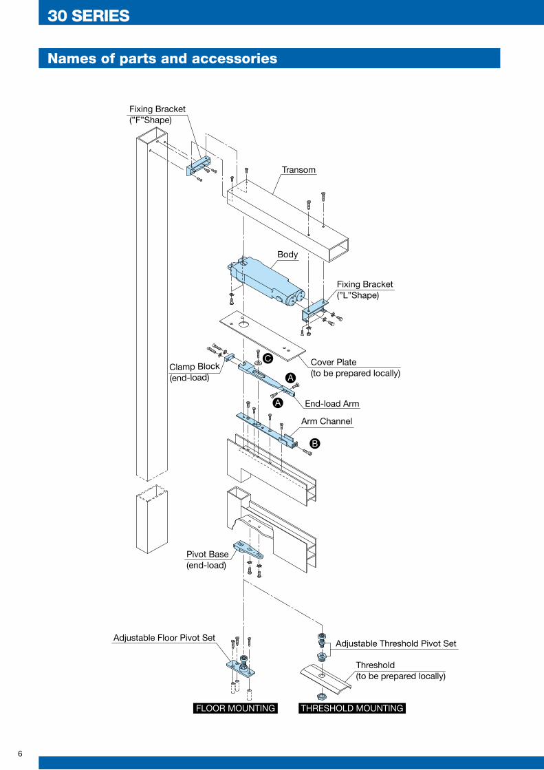
Fixing Bracket(”L”Shape)
Clamp Block(side-load) Arm Channel
(option)
Pivot Base(side-load)
Adjustable Floor Pivot Set
Name Plate
Transom
Body
Side-load ArmB
Fixing Bracket(”F”Shape)
FLOOR MOUNTING THRESHOLD MOUNTING
C
A
ACover Plate(to be prepared locally)
Adjustable Threshold Pivot Set
Threshold(to be prepared locally)
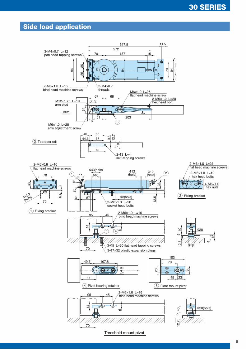
3 Top door rail
3
1
94 9470
35
94
35
73
11.5317.5272
1570 187
516
203
686736.5
34
44.540 66
57
75
1912
.79.
5
3
70
38
70
Φ12.7(hole) 6.
4
Φ43(hole)Φ40
12
11
20
Φ12(hole)
Φ12(hole)
38
673 Φ8(hole)
12.5
95 45
6
14
70
416
Φ26
Φ28405
12.7
70103
2345
20 36
67
34.6
49.7 107.6
14
95 45
70
6 Φ20(hole)
flat head machine screw
arm stud
socket head bolts
hex head bolt
arm adjustment screw
3-M4×0.7 L=12
2-M6×1.0 L=16bind head machine screws
bind head machine screws
bind head machine screws
flat head machine screws flat head machine screws
pan head tapping screws
2-M4×0.7threads
M6×1.0 L=28
M12×1.75 L=19
M6×1.0 L=25
2-M6×1.0 L=20
2-Φ3 L=4self-tapping screws
Arm
2-M5×0.8 L=10
hex head bolts
hex nuts
2-M6×1.0 L=25
2-M6×1.0 L=12
4-M6×1.0
2-M6×1.0 L=20
2-M6×1.0 L=16
3-Φ7×32 plastic expansion plugs3-Φ5 L=30 flat head tapping screws
2-M6×1.0 L=16
1 Fixing bracket
Fixing bracket2
5 Floor mount pivot 4 Pivot bearing retainer
2
45
405
12.7
Threshold mount pivot
Side load application
4 5
30 SERIES30 SERIES
Names of parts and accessories
Fixing Bracket(”L”Shape)
Clamp Block(side-load) Arm Channel
(option)
Pivot Base(side-load)
Adjustable Floor Pivot Set
Name Plate
Transom
Body
Side-load ArmB
Fixing Bracket(”F”Shape)
FLOOR MOUNTING THRESHOLD MOUNTING
C
A
ACover Plate(to be prepared locally)
Adjustable Threshold Pivot Set
Threshold(to be prepared locally)
3 Top door rail
3
1
94 9470
35
94
35
73
11.5317.5272
1570 187
516
203
686736.5
34
44.540 66
57
75
1912
.79.
5
3
70
38
70
Φ12.7(hole) 6.
4
Φ43(hole)Φ40
12
11
20
Φ12(hole)
Φ12(hole)
38
673 Φ8(hole)
12.5
95 45
6
14
70
416
Φ26
Φ28405
12.7
70103
2345
20 36
67
34.6
49.7 107.6
14
95 45
70
6 Φ20(hole)
flat head machine screw
arm stud
socket head bolts
hex head bolt
arm adjustment screw
3-M4×0.7 L=12
2-M6×1.0 L=16bind head machine screws
bind head machine screws
bind head machine screws
flat head machine screws flat head machine screws
pan head tapping screws
2-M4×0.7threads
M6×1.0 L=28
M12×1.75 L=19
M6×1.0 L=25
2-M6×1.0 L=20
2-Φ3 L=4self-tapping screws
Arm
2-M5×0.8 L=10
hex head bolts
hex nuts
2-M6×1.0 L=25
2-M6×1.0 L=12
4-M6×1.0
2-M6×1.0 L=20
2-M6×1.0 L=16
3-Φ7×32 plastic expansion plugs3-Φ5 L=30 flat head tapping screws
2-M6×1.0 L=16
1 Fixing bracket
Fixing bracket2
5 Floor mount pivot 4 Pivot bearing retainer
2
45
405
12.7
Threshold mount pivot
Side load application
4 5
30 SERIES30 SERIES
Names of parts and accessories
Cover Plate(to be prepared locally)
End-load Arm
Clamp Block(end-load)
Pivot Base(end-load)
Adjustable Threshold Pivot Set
Threshold(to be prepared locally)
Fixing Bracket(”L”Shape)
Arm Channel
Adjustable Floor Pivot Set
Transom
Body
B
FLOOR MOUNTING THRESHOLD MOUNTING
C
A
A
Fixing Bracket(”F”Shape)
Threshold mount pivot
132598867
35.5
2674240 39 66 66
10
7
66
6.4
12.8
38205
3.2
25
36
16
16Φ8(hole)
6
673
70
12829
16
98.5 42.5
hex head bolt
arm adjustment screw
4-M6-1.0×16 cross recessed
cross recessed pan head machine screws
2-M6×1.0 L=20
2-M6×1.0 L=16
bind head machine screws threads
bind head machine screws
bind head machine screws
flat head machine screws
flat head machine screws
pan head tapping screws
M6×1.0 L=14
2-M6×1.0 L=16
hexagon socket head boltsM6×1.0 L=20
3-Φ7×32 plastic expansion plugs3-Φ5 L=30 flat head tapping screws
1
Arm
flat head machine screws
hex head bolts
hex nuts
2-M6×1.0 L=25
2-M6×1.0 L=12
4-M6×1.0
2
Φ28
3
94 9470
35
94
35
73
11.5317.5272
1570 1873-M4×0.7 L=12
2-M6×1.0 L=16 2-M4×0.7
38
70
2-M5×0.8 L=10
3
70
1
12
11
20
3
5 4
Φ43(hole)Φ40
Φ12(hole)
Φ12(HOLE)
38
2
98.5 42.5
16
416
Φ26
405
12.7
34.6
4
67
70103
2345
20 36
5
70
6
2-M6×1.0 L=16
Φ20(hole)405
12.7
Arm channel
Fixing bracket
Fixing bracket
Floor mount pivot Pivot bearing retainer
End load application
6 7
30 SERIES30 SERIES
Names of parts and accessories
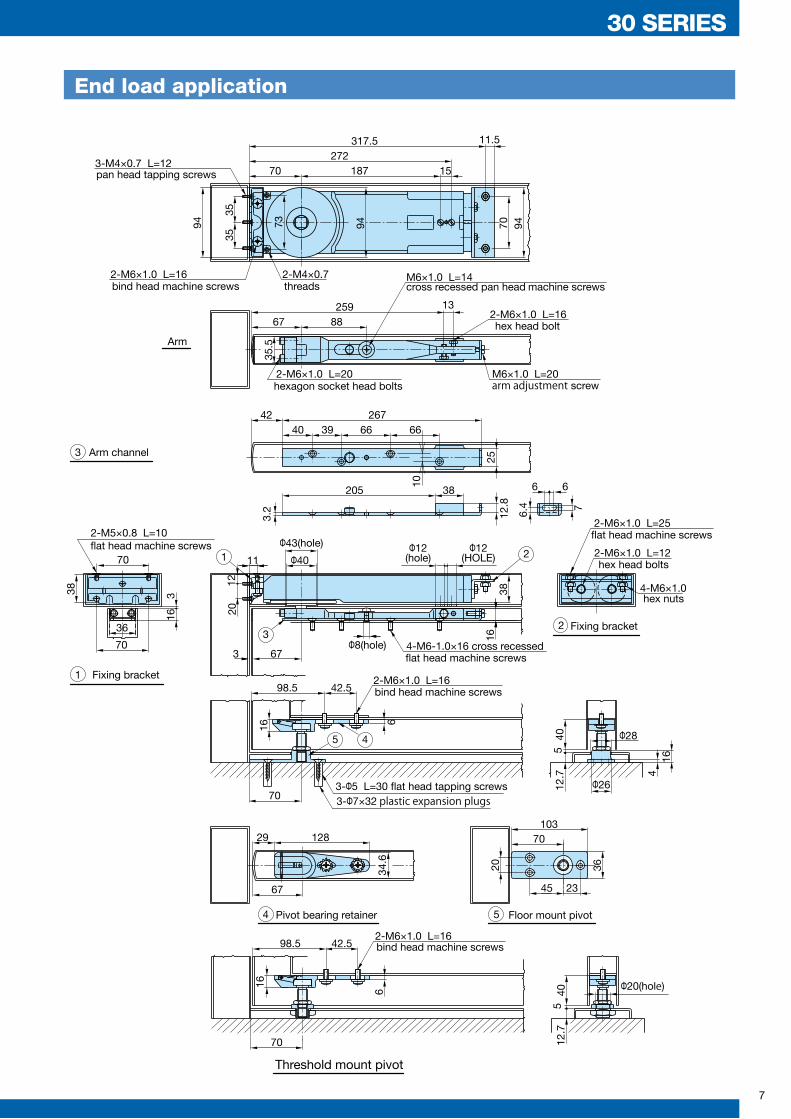

30 SERIESRYOBI
RYOBI LIMITED5-2-8 Toshima, Kita-ku Tokyo 114-8518, JapanTel. 81-3-3927-5536 Fax. 81-3-3927-5527RYOBI is a registered trade mark of Ryobi Limited
■Overhead Concealed Door Closers◆Cerradores ocultos arriba●Ferme-porte superieur dissimule
1,000,000cycles
Steel Alumi. WoodStain.
Closing positionadjustable
Clearanceadjustable 90 105