Embed Size (px)
Citation preview

S-60/S64 E v2 / EVEFirmware version 2.20
H.264 Video encoder series
Use
r M
an
ual

Note: To ensure proper operation, please read this manual thoroughly before using theproduct and retain the information for future reference.
Copyright © 2018 Siqura B.V.All rights reserved.
S-60/S-64 E v2 / EVE 2.20 User Manual v8 (181510-8)AIT55
Nothing from this publication may be copied, translated, reproduced, and/or published bymeans of printing, photocopying, or by any other means without the prior written permissionof Siqura.
Siqura reserves the right to modify specifications stated in this manual.
Brand namesAny brand names mentioned in this manual are registered trademarks of their respectiveowners.
LiabilitySiqura accepts no liability for claims from third parties arising from improper use other thanthat stated in this manual.
Although considerable care has been taken to ensure a correct and suitably comprehensivedescription of all relevant product components, this manual may nonetheless contain errorsand inaccuracies. We invite you to offer your suggestions and comments by email [email protected]. Your feedback will help us to further improve our documentation.
How to contact usIf you have any comments or queries concerning any aspect related to the product, do nothesitate to contact:
Siqura B.V.Meridiaan 322801 DA GoudaThe Netherlands
General : +31 182 592 333Fax : +31 182 592 123E-mail : [email protected] : https://siqura.com
2

Contents1 S-60/S-64 E v2 / EVE Help ........................................................................ 5
2 Meet the S-60/64 E v2 family .................................................................... 6
3 Meet the EVE family .................................................................................. 7
4 Get access to the unit ................................................................................ 9
4.1 Get access via web browser .................................................................. 94.2 Get access via Device Manager .............................................................. 94.3 Get access via UPnP ............................................................................. 104.4 Log on to the unit ................................................................................ 10
5 Webpage features ..................................................................................... 11
6 Live Stream ............................................................................................... 12
7 Camera ..................................................................................................... 15
7.1 Camera Management ........................................................................... 157.2 Image Quality ..................................................................................... 167.3 Overlays ............................................................................................. 177.4 Streaming Profiles ............................................................................... 197.5 PTZ ................................................................................................... 227.6 Privacy Mask ....................................................................................... 24
8 Event ......................................................................................................... 25
8.1 Event Management .............................................................................. 258.2 Connection Monitor .............................................................................. 258.3 Digital I/O .......................................................................................... 268.4 FTP Push ............................................................................................ 27
9 Recording .................................................................................................. 28
9.1 Camera-# ........................................................................................... 289.2 SD Card ............................................................................................. 299.3 NAS recording ..................................................................................... 30
9.3.1 Server settings ................................................................................ 30
10 Device ....................................................................................................... 32
10.1 Device Management ............................................................................. 3210.2 Network ............................................................................................. 3310.3 Date & Time ........................................................................................ 3610.4 Security ............................................................................................. 3710.5 User Management ................................................................................ 3910.6 SNMP ................................................................................................. 40
11 Diagnostics ............................................................................................... 42
11.1 Logging .............................................................................................. 4211.2 LED ................................................................................................... 42
12 Analytics ................................................................................................... 43
12.1 Motion Detection ................................................................................. 4312.2 Tampering .......................................................................................... 44
3

12.3 Quality Monitor .................................................................................... 45
13 Advanced .................................................................................................. 46
13.1 Direct Streaming ................................................................................. 4613.2 Data .................................................................................................. 4713.3 Audio ................................................................................................. 4813.4 RTSP .................................................................................................. 48
14 Troubleshooting ........................................................................................ 49
14.1 Date & Time issues .............................................................................. 4914.2 FTP issues .......................................................................................... 4914.3 Logon issues ....................................................................................... 4914.4 Network issues .................................................................................... 5014.5 PTZ issues .......................................................................................... 5014.6 Upgrade issues .................................................................................... 5114.7 Video issues ........................................................................................ 5114.8 Webpage issues ................................................................................... 52
Acknowledgements ................................................................................... 53
Index ...................................................................................................... 54
Contents
4

1 S-60/S-64 E v2 / EVE HelpWhat's in this manualThis is version 8 of the user assistance for the S-60/S-64 E v2 and EVE video encoders withfirmware version 2.20. It is made up of the Help topics that you can open from the webinterface of these units. The topics describe:
● How to operate the unit
● How to adjust device settings
● How to manage user accounts
● How to resolve occurred issues
Note: Functions described in this generic Help information may be supported by all encodersor by specific models only. When describing shared features, this manual uses the genericterm "unit" to refer to the S-60/S-64 E v2 and the EVE encoders. In descriptions ofdistinguishing features, the individual product name is used.
Where to find more informationFind product specific datasheets, manuals, EU Declarations of Conformity and firmwareupdates at siqura.com/downloads/software. Make sure that you have the latest version of thismanual.
Who this manual is forThese instructions are for all professionals who will install, operate or maintain this unit.
What you need to knowYou will have a better understanding of how this product works if you are familiar with:
● CCTV systems and components
● Ethernet network technologies and Internet Protocol (IP)
● Windows environments and web browsers
● Video, audio, data, and contact closure transmissions
● Video compression methods
Why specifications may changeWe are committed to delivering high-quality products and services. The information given inthis manual was current when published. As we continuously seek to improve our productsand user experience, all features and specifications are subject to change without notice.
We like to hear from you!Customer satisfaction is our first priority. We welcome and value your opinion about ourproducts and services. Should you detect errors or inaccuracies in this manual, we would begrateful if you would inform us. We invite you to offer your suggestions and comments [email protected]. Your feedback helps us to further improve our documentation.
AcknowledgementThis product uses the open-source Free Type font-rendering library. The Open SourceLibraries and Licenses document, available at siqura.com/downloads/software, gives acomplete overview of open source libraries used by our video encoders and IP cameras.
5

2 Meet the S-60/64 E v2 family
S-60 E v2● One-channel H.264 video encoder
● ONVIF Profile S
● Edge recording
● Picture enhancement
● Image quality monitor
● Advanced tamper detection
● 960H Support
● Duplex serial data
● Open Streaming Architecture (OSA)
● Available with SFP interface
● NAS recording
S-64 E v2● Four-channel H.264 video encoder
● ONVIF Profile S
● Edge recording
● Picture enhancement
● Image quality monitor
● Advanced tamper detection
● 960H Support
● Duplex serial data
● Open Streaming Architecture (OSA)
● Available with SFP interface
● NAS recording
6
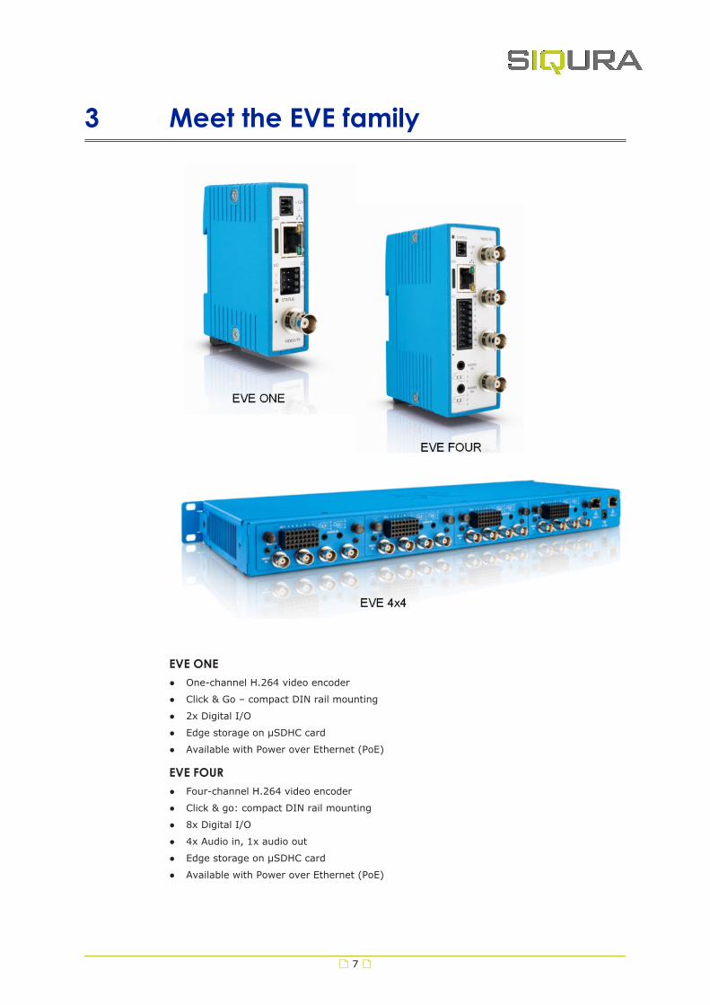
3 Meet the EVE family
EVE ONE● One-channel H.264 video encoder
● Click & Go – compact DIN rail mounting
● 2x Digital I/O
● Edge storage on μSDHC card
● Available with Power over Ethernet (PoE)
EVE FOUR● Four-channel H.264 video encoder
● Click & go: compact DIN rail mounting
● 8x Digital I/O
● 4x Audio in, 1x audio out
● Edge storage on μSDHC card
● Available with Power over Ethernet (PoE)
7

EVE 4x4● Modular 4x four-channel H.264 encoder
● Edge storage on μSDHC card (4x)
● 4x 4 Audio in; 4x 1 audio out
● 4x 8 Digital I/O
EVE family shared features● High resolution: 960 H support (960x576 pixels)
● Advanced picture enhancement
● Image quality monitoring
● Tamper detection
● ONVIF Profile S
● NAS recording
Meet the EVE family
8

4 Get access to the unitFrom a standard browser on your PC, you can connect to the web interface of the unit. Usethe webpages to view live video over the network, remotely operate the PTZ functions, andconfigure the settings of the unit. This chapter explains how to open the web interface in yourbrowser.
In This Chapter4.1 Get access via web browser..................................................................................... 9
4.2 Get access via Device Manager.................................................................................9
4.3 Get access via UPnP.............................................................................................. 10
4.4 Log on to the unit................................................................................................. 10
4.1 Get access via web browserConnect to the unit from your web browser1 Open your web browser.
2 Type the IP address of the unit in the address bar.
The factory-set IP address of the unit is in the 10.x.x.x range.
3 Press ENTER.
The Live Stream page is opened.
- or -
If user accounts exist on the unit, you are directed to the login page (see "Log on to theunit" on page 10).
4.2 Get access via Device ManagerDevice Manager is a Windows-based software tool that you can use to manage and configureour cameras and video encoders. The tool automatically locates these devices on the networkand offers you an intuitive interface to set and manage network settings, configure devices,show device status, and perform firmware upgrade.
Install Device Manager1 Download the latest version of Device Manager at siqura.com/downloads/software.
2 Double-click the setup file.
3 Follow the installation steps to install the software.
Connect to the unit via Device Manager1 Start Device Manager
The network is scanned.
Detected devices appear in the List View pane.
2 If multiple network adapters exist, select the appropriate adapter to scan the networkthat you wish to connect to.
3 To perform a manual search, click the Rescan button.
9

4.3 Get access via UPnPUniversal Plug and Play (UPnP) support is enabled by default on the unit. With the UPnPservice enabled in Windows, you can get access to the unit from Windows Explorer.
Connect to the unit via UPnP1 In Windows Explorer, open the Network folder.
Detected devices in the same subnet as the computer are displayed, including codecsand cameras with UPnP support.
2 Double-click the unit that you want to connect to.
The Live Stream page is opened.
- or -
If user accounts exist on the unit, you are directed to the login page (see "Log on to theunit" on page 10).
4.4 Log on to the unitBy default, users can freely open the web interface of the camera. They are not required tolog on.
User authentication
If user accounts have been created and user authentication is activated, you encounter anauthentication box when you connect. You are prompted to supply your user name andpassword. Only users with a valid account can log on.
Log on to the unit1 In User Name, type your user name.
User name and password are case sensitive.
2 In Password, type your password.
3 Click Log In.
Use strong passwordsCAUTION: MAKE SURE YOU CREATE AN ADMIN ACCOUNT WHEN YOU OPEN THE WEBINTERFACE FOR THE FIRST TIME. TO KEEP THE ACCOUNT SAFE, SET A STRONG, COMPLEXPASSWORD. THIS HELPS TO PREVENT UNAUTHORISED ACCESS.
Create a strong password● Use at least eight characters
● Do not include your real name, user name, company name, or other personal information
● Do not use complete words that can be found in a dictionary
● Use a random combination of at least two of the following categories: upper case letters,lower case letters, numbers and special characters
Note: For better protection, especially in high-security systems, we advise you to changethe password at regular intervals.
Get access to the unit
10

5 Webpage featuresThe built-in web interface makes it easy to operate and configure your product over thenetwork. This section describes the layout and main features shared by the webpages.
Embedded Help
Help topics embedded in the webpages provide context-sensitive user assistance. Forinformation about items and settings found on a page, click the question mark (Show help) inthe Title bar of the page.
Note: The Embedded Help topics offer generic Help information for a range of Siquraproducts. Whether or not a described feature, mode or setting is available on the unit athand depends on the model you purchased.
Home page
The Live Stream page is the home page of the unit. It is opened after successfully connectingto the web interface.
Note: Out of the box, the unit is freely accessible. You are not prompted to log on. Toprevent unauthorised access, we recommend that you implement user authentication. This isdone by creating user accounts and activating user login. For more information, see UserManagement.
Menu
Use the vertical menu on the left to navigate the web interface. Clicking a menu entry opens apage or a submenu.
Nice to know
To find a specific webpage quickly, type its name in the search-as-you-type boxabove the menu.
Layout
Webpages have a single-page layout or content is organised across a number of tabs. A tabcontains related commands and settings. The title of the active tab is highlighted andunderlined.
Previews
Pages such as Live Stream, Overlays, Motion Detection, and Tampering include a camerapreview. You use it to view live video or determine the effect of your settings when you makechanges.
Revert button
A Revert button appears when you adjust specific settings. It lets you undo your changes. Thebutton is available until you leave the webpage.
Restore the setting to its original state (at the time of opening the webpage).
11
6 Live StreamThe Live Stream page is the home page of the unit. This is where you can:
● View and record live video
● Take snapshots
● Control a connected PTZ camera
● Adjust the focus and iris
Layout
The Live Stream page is taken up entirely by the camera preview. On multichannel units,video from the connected cameras can be viewed in single-view or quad-view mode.
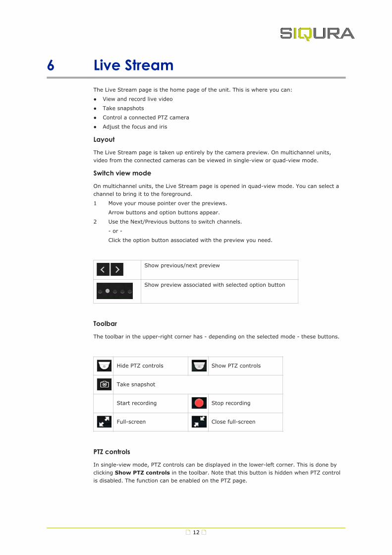
Switch view mode
On multichannel units, the Live Stream page is opened in quad-view mode. You can select achannel to bring it to the foreground.
1 Move your mouse pointer over the previews.
Arrow buttons and option buttons appear.
2 Use the Next/Previous buttons to switch channels.
- or -
Click the option button associated with the preview you need.
Show previous/next preview
Show preview associated with selected option button
Toolbar
The toolbar in the upper-right corner has - depending on the selected mode - these buttons.
Hide PTZ controls Show PTZ controls
Take snapshot
Start recording Stop recording
Full-screen Close full-screen
PTZ controls
In single-view mode, PTZ controls can be displayed in the lower-left corner. This is done byclicking Show PTZ controls in the toolbar. Note that this button is hidden when PTZ controlis disabled. The function can be enabled on the PTZ page.
12

Important: In the web interface and in this manual, these controls are referred to as "PTZcontrols". Note, however, that a fixed camera connected to the unit does not have pan/tilt(PT) functionality. The zoom (Z) function is supported though - that is, if PTZ control isenabled.
Take a snapshot
It is possible to take a snapshot of the video in the preview.
● Click Take snapshot.
The picture is saved in JPG format to the designated folder.
The file name includes the camera name and date/time information.
Record a live stream
A video stream shown in the preview can be recorded and downloaded to your PC.
1 Click Start recording.
The button flashes red to show you started a recording.
2 To stop the recording, click Stop recording.
The recording is saved in AVI format to the designated folder.
The file name includes date/time information.
Enter full-screen mode
For better observation, you may want to enter full-screen mode.
● Click Full-screen.
The preview fills the entire screen.
Clicking Close full-screen or pressing [Esc] on your keyboard takes you back to standardmode.
Video streaming
Video streaming can be started and paused with the Play and Pause buttons in the centre ofthe preview. These buttons are available when the PTZ controls are hidden.
Play live video stream
Pause live video stream
Pan/Tilt a camera
A PTZ camera connected to the unit can be controlled from the Live Stream page.
1 Go to the PTZ page to make sure that PTZ control is enabled for the camera.
2 On multichannel units, click the Next/Previous buttons to select the camera you wishto control.
3 In the upper-right corner, click Show PTZ controls.
4 To pan/tilt the camera, drag your mouse pointer across the preview in the direction youneed.
Clicking in the preview also moves the camera.
Live Stream
13

Adjust zoom, focus, and iris
To zoom the camera or adjust the focus and iris, use the sliders in the lower-left corner of thepreview. Drag the slider to the left or right and watch the preview until you achieve thedesired effect.
Create a PTZ preset
Camera positions can be stored as PTZ presets.
1 Pan, tilt, zoom and focus the camera as needed.
2 Click Store current position as preset (the Star button).
The preset is added to the list with a number to identify it.
3 Type a descriptive name in the Preset text box.
You can also name and rename presets on the PTZ page.
Recall a PTZ preset
Camera positions stored as PTZ preset can be recalled.
● In the PTZ preset list, click the required preset.
The camera adopts the recorded position.
Delete a PTZ preset
Camera positions stored as a PTZ preset can be deleted when no longer needed.
1 In the PTZ preset list, click the preset you want to delete.
2 Click Delete preset (the Recycle button).
Note that a deleted preset is irretrievably lost! You are therefore asked to confirm thedeletion.
You can delete multiple presets in one go on the PTZ page.
Live Stream
14
7 CameraOn the webpages grouped under Camera, you can adjust the settings for cameramanagement, image quality, overlays, video streaming and PTZ.
In This Chapter7.1 Camera Management.............................................................................................15
7.2 Image Quality...................................................................................................... 16
7.3 Overlays..............................................................................................................17
7.4 Streaming Profiles.................................................................................................19
7.5 PTZ.....................................................................................................................22
7.6 Privacy Mask........................................................................................................ 24
7.1 Camera ManagementNote: Available functions and settings on this page vary from model to model.
Name
In Name, type a name for the camera. Use a unique, descriptive name so that you can easilyidentify it on the network. The camera name can be enabled as an overlay so that it is visiblein the previews and in video streams transmitted by the camera.
Input
A video input is enabled by default. You can choose to set it to Disabled. This is typically donewhen no video signal is connected to an input. If you disable the input:
● No “Video loss”, “Image quality” and “Tamper detect” alarms will be raised.
● The blue screen with “No Video” is not shown when no input signal is connected.
● A black image with reduced frame rate with only the OSD-texts will be streamed.
Aspect ratio
This setting lets you adjust the proportional relationship between the width and the height ofthe preview images shown in the web interface.
Input impedance
Impedance is the measure of resistance to signal current flow. With one video source on onevideo input, select 75 Ohm. With a number of video inputs in parallel using one video source,use High-Z on all inputs except the last.
Video standard
The video display standard you select here - PAL, NTSC, or Auto - determines the availableframe rates on the Streaming Profiles page - that is 25 fps for PAL and 30 fps for NTSC.
15

7.2 Image QualityOn the Image Quality page, image quality settings are overlaid over the video in the preview.Use these settings to enhance the image quality for optimal display in your web browser or inan application you are using to extract the video stream. Any changes you make areimmediately effective and visible in the preview.
Note: On multichannel units, use the Next/Previous buttons to go to the camera you need,and then make the required changes.
Noise filter
It is possible to (partially) remove noise from the video signal.
1 Click the Noise filter list.
2 Select Weak, Average, or Strong as required.
Selecting Off disables the filter.
Auto-enhancement
When set to On, this function continuously analyses the images and dynamically adjusts theimage quality to compensate for changing conditions.
Manual enhancement
Image quality can be controlled manually.
1 Set Auto-enhancement to Off.
2 While observing the changes in the preview, move the Brightness, Contrast,Sharpness, Colour saturation, and Hue sliders until you achieve optimal viewingquality.
Note: With manual enhancement, the settings are not dynamically adjusted when conditionschange.
Brightness
Use this function to adjust the brightness level of the video images to your viewing conditions.
Contrast
Use this function to adjust the contrast level of the video images to your viewing conditions.
Sharpness
Use this function to adjust image sharpness to your viewing conditions.
Color saturation
Use this function to adjust the intensity (purity) of the colours in the video images.
Hue
Use this function to enhance the colours in the video images if they do not look natural.
Camera
16

7.3 OverlaysOn the Overlays page, text can be superimposed on the video streamed by the unit. You can,for example, have the camera name, date and time information, measurements or a customtext displayed. Depending on model, you can also add an image overlay, such as a logo.
Note: On multichannel units, use the Next/Previous buttons to go to the camera you need,and then make the required changes.
Layout
The greater part of the Overlays page is taken up by the preview. To the right of it, you findthe functions for overlay creation, overlay alignment, font management and imagemanagement.
Section Functions
Overlay settings ● Add/Modify/Delete text overlays
● Add/Modify/Delete an image overlay
● Set overlay position
● Set overlay appearance
Overlay alignment ● Move overlay to left/right
Font management ● Upload/Delete a font
Image management ● Upload/Delete an image
Toolbar
Overlay toolbar buttons vary from model to model.
Button Name
Add text overlay
Add image overlay
Add a text overlay
You can add up to three text overlays.
1 In the toolbar, click Add text overlay.
A shape with a green border is added to the preview.
2 Click the shape to open the shape settings.
3 Type your custom text in the text box located in the Selected shape section.
- or -
Click the button to the left of the text box, and then select a predefined entry.
It is possible to reopen the list and click a different entry to append to the selectionalready in the text box.
4 In the Render mode list, select Outline or Border as needed.
Camera
17

Your adjustment is immediately effective. See the preview for visual feedback.
5 Click Position.
6 In the Position list, select a preset position.
- or -
Click Free positioning and type custom values in the X position and Y position boxesto freely place the shape over the video image. Using the options in the Anchor pointlist, you can shift the object relative to the anchor point.
You can also position the shape using a drag-and-drop operation.
7 (Optional) Use the Rotation angle slider to rotate the text.
8 Click Colour.
9 Select a font colour and a border colour.
10 (Optional) Drag the Transparency slider to set the transparency level of the text.
11 Click Font.
12 Select the font to be used.
Using the Font management section, you can upload your own fonts to the unit.
13 Enter the font size.
As an alternative, you can freely adjust the font size by dragging the resizing handles ofthe shape.
Add an image overlay
An image that you have uploaded via Image management can be overlaid on the video.
1 In the toolbar, click Add image overlay.
An image shape is added to the preview.
2 Click the image to open the shape settings.
3 In the Image list, select the image to be used.
4 Click Position.
5 In the Position list, select one of the preset positions.
- or -
Click Free positioning and type custom values in the X position and Y position boxesto freely place the shape over the video image. Using the Anchor point setting, you canshift the shape relative to the anchor point.
You can also position the shape using a drag-and-drop operation.
6 Click Advanced.
7 (Optional) Drag the Transparency slider to set the transparency level of the image.
8 (Optional) Drag the X scale and Y scale sliders to adjust the scaling of the image.
As an alternative, you can freely adjust the scaling by dragging the resizing handles ofthe shape.
9 (Optional) If your overlay is an animated GIF image, define its speed in Animationspeed.
Delete an overlay1 Click the overlay shape in the preview.
2 In the Selected shape section, click the Recycle Bin button.
Upload a font1 Click the arrow which expands Font Management.
2 Drag the font file onto the dashed rectangle.
- or -
Use Click to select file to locate and select the file.
3 Click Upload.
Camera
18

Delete a font1 Click the arrow which expands Font Management.
2 Click Select font to delete.
3 Click the font you wish to delete.
4 Click Delete.
Upload an image1 Click the arrow which expands Image Management.
2 Drag the image file onto the dashed rectangle.
- or -
Use Click to select file to locate and select the file.
The unit supports .GIF and .JPG files.
3 Click Upload.
Delete an image1 Click the arrow which expands Image Management.
2 Click Select image to delete.
3 Click the image you wish to delete.
4 Click Delete.
7.4 Streaming ProfilesDual streaming
Per channel, the unit can take the analogue video signal from the connected camera andconvert it into two independent digital video streams with different video encoding settings.
Streaming profile types
A straightforward method of configuring the encoding settings for a video stream is to use afactory-set streaming profile - that is, a predefined combination of settings for a specificapplication. The unit offers profiles optimised for video storage, PTZ, or high-quality liveviewing, for example. If none of the factory profiles meets your requirements you can createand save user-defined streaming profiles.
Use a factory-set profile
A factory-set streaming profile defines the settings that the unit will use for the applicationindicated by the profile name.
1 Click the camera name at the top of the webpage.
2 Click Stream 1 or Stream 2 to select the stream to assign the streaming profile to.
3 In the Profile list (below the Stream tabs), select the factory profile which isappropriate for (or comes closest to) the intended purpose.
4 Repeat steps 1 through 3 for the other stream, if necessary.
Factory profile settings
When you select a factory profile, the video stream will be encoded with the settings shownbelow the profile list. For several of these settings, the actual value is shown to the right ofthe defined value.
Camera
19

Create a custom profile
If the supplied factory-set profiles do not meet your requirements you can create a customstreaming profile.
1 Click the camera name at the top of the webpage.
2 Click Stream 1 or Stream 2, to select the stream to assign the streaming profile to.
3 In the Profile list, select the factory profile to be used as a basis for the custom profile.
4 Adapt the profile settings to your requirements.
The custom profile is added to the Profile list (User section) as: Factory profile-Copy-yymmdd.
5 To rename the profile, type a descriptive name into the Name box.
Delete a custom profile
Custom streaming profiles can be deleted (unlike factory-set profiles).
1 In the Profile list, select the profile to be deleted.
2 Click Delete.
3 In the information bar, click Yes, delete to confirm this action.
Name
Indicates the currently selected streaming profile. You can name and rename customstreaming profiles. The names of the factory-set profiles cannot be changed.
Encoder type
Depending on the application, select the video encoding method that is to be used tocompress the video signal.
Frame rate
Here you can set the number of video frames per second for the video transmission. Range:1-25 fps (PAL); 1-30 fps (NTSC).
GOP size
Determines the distance in frames between two I-frames.
Maximum bit rate
Here you can set the maximum bit rate allowed for the video transmission. You can use thissetting to control the network load. The actual bit rate is shown to the right of the text box.This value is dynamically updated with the current bit rate to provide feedback on the bit ratethat is used on average with the current Maximum quality setting.
Maximum quality
Generally speaking: the higher the Maximum quality setting, the lower the compression ratioand the more bits are consumed. This means a trade-off has to be found between the desiredquality level and available bandwidth. When configuring these settings it is good to keep thefollowing in mind.
● If the configured Maximum quality cannot be achieved with the currently set Maximum bitrate, the actual quality will be lower. The actual quality percentage is shown real-time tothe right of the configured Maximum quality.
● The actual quality level will never exceed the configured Maximum quality, even if theMaximum bit rate should allow it.
Resolution
Indicates the number of pixels that can be displayed in each dimension (width x height). Seethe table below for supported resolutions.
Camera
20

PAL NTSC960H 960x576 960x480
D1 720x576 720x480
2/3 D1 480x576 480x480
1/2 D1 352x576 352x480
4CIF 704x576 704x480
2CIF 720x288 720x240
CIF 352x288 352x240
QCIF 176x144 176x120
VGA 640x480 640x480
QVGA 320x240 320x240
Traffic shaping
Traffic shaping sets the maximum network bit rate per encoder. Traffic shaping will spreadnetwork traffic bursts which helps the network infrastructure handle the traffic. In its turn,however, traffic shaping will increase the latency.
● With traffic shaping set to Off, the stream is transmitted with minimum latency but withbursty network traffic.
● With traffic shaping set to Low, Medium or High, the network traffic is more evenly spreadout in time, but the latency will increase.
Parameter value combinations
When you create a custom streaming profile, set sensible combinations of Frame rate, GOPsize, Maximum bit rate, Maximum long term bit rate, Maximum quality, and Resolution. If indoubt about the effects of specific encoder settings, you are advised to select the factory-setprofile offering the closest match to your required application.
Use Quad view
To see live video from the S-64 E v2, you can use a web browser or video viewing software.In a browser, the Live Stream page presents the four camera views arranged in quad layout.For closer viewing, you can select an individual camera. Likewise, if you use viewing softwareto extract video, you can request a quad view RTSP stream or open a separate RTSP streamper channel. Note that the unit's Quad view function is disabled by default.
1 On the Quad view tab, click Enable.
2 Configure the encoding settings as needed.
3 In your viewing application, specify the URL containing the IP address of the S-64 E v2.
4 Add "/quad" after the IP address.
For example: rtsp://10.50.3.72/quad
On successful connection, the S-64 E v2 quad view is streamed to your application.
Tip: Depending on the chosen settings, the overall performance will be reduced when thequad view stream is enabled. To prevent reduced frame rate or increased latency, it isrecommended to set any unused streams to low resolution and low frame rate.
Camera
21

7.5 PTZOverview
The PTZ page has the following tabs:
● Camera-#
Use this tab to enable PTZ camera control from your browser, assign an ID to the cameraand manage the PTZ presets you have created on the Live Stream page.
● Driver management
Use this tab to activate PTZ control, upload and delete PTZ drivers, and configure datasettings.
PTZ control
On the Camera-# tab, select/clear the Enable check box to enable/disable PTZ operation fromyour web browser.
Camera ID
In order to address multiple cameras on the same RS-485 bus, each camera needs to beassigned a unique ID. Make sure to set all connected cameras to a different ID on the cameraitself, and then set the camera IDs for all cameras accordingly on this page.
1 Click the Camera-# tab.
2 In the Camera ID box, type the ID.
Rename a preset
Presets are automatically saved as "PTZ preset #" followed by the preset number. On the
Camera # tab, you can rename a preset to give it a more descriptive name.
1 In the Preset name column, click the current name of the preset.
2 Type the new preset name.
The preset can now be found under the new name in the Preset list on the Live Streampage.
Add a reserved preset
Certain functions of a connected camera (such as a wiper/washer system, for example) can beactivated by working with reserved presets, if the camera supports these.
1 Click Add Reserved Preset.
A new row is added to the preset table.
2 Click the appropriate cell under Preset number and type the number that will activatethe camera function.
3 Click the corresponding cell under Preset name and type a descriptive name.
The preset is added to the preset list on the Live Stream page.
Delete PTZ presets
Note that it is not possible to undo the deletion of a preset!
1 Click to select the check box(es) of the preset(s) you wish to delete.
2 Click Delete preset.
You are asked to confirm the deletion.
Upload a PTZ driver
PTZ drivers not included in the factory-default driver list can be uploaded to the unit.
1 On the Driver management tab, click Upload driver.
Camera
22

2 Drag the driver file (with .js file extension) onto the dashed rectangle.
3 Click Upload.
The driver is added to the User section of the driver list.
Delete a PTZ driver
Uploaded drivers that you no longer need can be deleted. It is not possible to delete thefactory-installed drivers.
1 On the Driver management tab, click the list of available drivers.
2 Click the driver you wish to delete.
3 Click Delete.
PTZ commands over TCP
The unit supports the streaming of PTZ data over TCP using a client/server connection. TheTCP connection is bidirectional.
1 In the Listening on port box, specify the port on which the server listens for incomingTCP connections.
Range: [0 ... 65535]. Default: 1024.
2 To activate this function, select Enable.
Bit rate
Determines the speed of the digital transmission - that is, the amount of informationtransferred/processed per unit of time.
TX/RX
The TX and RX indicators next to the Bit rate setting are highlighted in green when data istransmitted (TX) or received (RX) via the serial port.
Word length
Determines the number of bits that is transferred in a single operation.
Stop bits
Indicates the end of a data character to enable the receiver to resynchronise with the stream.
Parity mode
Enables the sending of an extra bit with each data character for error detection purposes.
Wire mode
The RX-4xx interface type on the data connector is set in software. Select the required type inthe Wire mode list.
Biasing
If biasing is needed, it should be enabled on at least one module on the bus.
Termination
Normally, the devices at the two extremes of a bus are terminated, while intermediate devicesare not. Therefore: RS-422, always enable (being point-to-point); RS-485, enable only for thefirst and last module connected to the bus configuration.
Camera
23

7.6 Privacy MaskTo avoid intrusive monitoring, privacy masks can be used to conceal sensitive areas within thefield of view of a camera.
Add a privacy mask
You can create up to ten privacy masks.
1 In the upper-right corner, click Add privacy mask.
The mask appears as an overlay.
2 Drag the mask to the area that you want to conceal.
3 Drag the sides of the mask to resize it.
It is recommended to set the mask to twice the size of the sensitive area.
4 In the Colour list (lower-left corner), select a colour for the mask.
Delete a privacy mask1 Click on the mask to select it.
2 In the upper-right corner, click the Recycling button (Delete privacy mask).
Camera
24

8 EventOn the Event pages, you can define how the unit is to handle incoming events.
In This Chapter8.1 Event Management............................................................................................... 25
8.2 Connection Monitor............................................................................................... 25
8.3 Digital I/O............................................................................................................26
8.4 FTP Push..............................................................................................................27
8.1 Event ManagementOn the Event Management page, you can link actions to specific events. Once the eventoccurs, it triggers the selected action automatically.
Add an event
The Event Management page is blank when you open it for the first time. You can add eventsby selecting a trigger and linking an action to it.
1 Click Add event.
2 In the Trigger column, click Select trigger.
3 In the Trigger list, select the event that will set off the trigger action.
4 In the Action column, click the corresponding cell.
5 In the Action list, select the action to be taken when the event occurs.
The event is effective as soon as you have defined the trigger and the action.
Note: Make sure that the FTP server settings are configured correctly when you select "FTPimage ..." as a trigger action.
Delete an event1 Select the check box of the event you wish to delete.
2 Click Delete event.
8.2 Connection MonitorThe Connection Monitor function can monitor the network connection between the unit and atarget host on the network. The unit pings the remote machine - that is, sends data packetsto it, at intervals of 15 seconds to determine if the remote machine is accessible andresponding.
Edge recording
To prevent loss of video when the connection to a central network video recorder or VMSsystem is lost, recorded video clips can be stored on the microSD card inside the edge device.From the Edge Recording page, the clips can then be downloaded for further processing.
25
Steps
Setting up the unit to record video to the SD card when a ping request times out without aresponse involves the following steps:
● On the Recording page, check the SD card status.
● On the Event Management page, add a "Connection # lost" trigger and link a "Startrecording of Camera #" action.
● On the Connection Monitor page, set up and enable the Connection Monitor to monitor theconnection to the VMS/NVR.
Set up the connection monitor1 In IP address, type the IP address of the remote machine that is to be pinged.
2 Click Enable to activate the monitor.
The connectivity status is given as "Connection present" or "Connection lost".
"Connection present" indicates that the remote machine responds to the ping
requests.
"Connection lost" indicates a network failure.
Connection loss
Detection of a connection loss to a device at a monitored IP address triggers the following:
● Edge recording starts at the first lost ping.
Important: Recording does not start if the device at the specified IP address has notbeen detected previously. In other words, recording is only possible for devices whichhave acknowledged their presence on the network at least once by responding to pingmessages. This is to prevent unintended recording to the microSD card.
● The connection loss is reported in the Connection Monitor page: "Connection lost".
● The associated video clip appears in the Available clips section on the Edge Recording pagewith clip status shown as 'Recording'.
● Edge recording continues until the device becomes responsive to ping messages again -that is, on the next received ping.
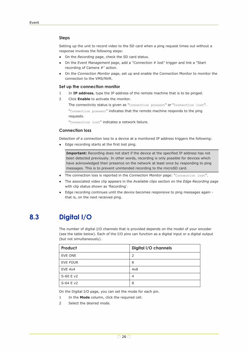
8.3 Digital I/OThe number of digital I/O channels that is provided depends on the model of your encoder(see the table below). Each of the I/O pins can function as a digital input or a digital output(but not simultaneously).
Product Digital I/O channelsEVE ONE 2
EVE FOUR 8
EVE 4x4 4x8
S-60 E v2 4
S-64 E v2 8
On the Digital I/O page, you can set the mode for each pin.
1 In the Mode column, click the required cell.
2 Select the desired mode.
Event
26

Mode DescriptionForce closed I/O contact is closed
Input I/O pin is input pin
Output (inverted) I/O pin is output pin (output inverted)
Output I/O pin is output pin
On the Event Management page, you can add events triggered by "I/O # closed" and defineactions to be taken when such events occur.
8.4 FTP PushOn the Event Management page, events can be set to trigger an FTP push. When such anevent occurs, the unit posts a camera image on one or two FTP servers. A target server musthold a user account associated with the unit. If you assign two servers, images are postedsimultaneously to FTP server 1 and FTP server 2.
Set up the FTP server connection1 Select the Enable check box of Send to this server.
2 In IP address, type the IP address of the FTP server you want to use.
3 In Port, type the port number to be used.
The FTP protocol typically uses port 21 on the FTP server to listen for clients initiating aconnection. Port 21 is also where the server is listening for commands issued to it.
4 In Name, type the user name that is needed for authentication before you can accessthe server.
5 In Password, type the password that is needed for authentication before you canaccess the server.
6 (Optional) Repeat steps 1-5 for the second FTP server.
On the Camera-# tab, you can set the path to an FTP server and configure settings forcontinuous posting.
Server path
In the Server path box, type the name of the folder on the FTP server which is assigned to theFTP client. Example: \Captures\Cam-1. This can be used if the client is not allowed to access
the server root folder.
Click Test FTP settings to make sure that the server path has been set correctly. A messagein the top of the screen will indicate if the camera has been able to make a connection withthe FTP server or not.
Continuous posting
Image upload to an FTP server can be event-triggered but you can also set it to becontinuous.
1 In Interval, type a value to determine the interval between two image posts.
2 In File name, type a descriptive name or accept the default name.
With the append button you can add extra information to the file name.
3 To activate continuous posting, select Enable.
Event
27

9 RecordingThe unit provides edge recording. This function makes it possible to record and store videolocally - that is, at the unit itself. Recorded video clips are stored on the microSD card insidethe unit. From the Edge Recording page, the clips can be downloaded for further processing.
In This Chapter9.1 Camera-#............................................................................................................28
9.2 SD Card...............................................................................................................29
9.3 NAS recording...................................................................................................... 30
9.1 Camera-#Record
Use the stream list at the top of the page to select Stream 1 or Stream 2 for recording.
Recording types
Two types of edge recording are available:
● Continuous recording
● Event-triggered recording
Recording source
Each camera input has multiple streams. In the Recording source list, select the stream tobe recorded.
Recording destination
Recordings can be stored either on an SD card or a configured NAS server. In the Recordingdestination list, select the desired storage medium.
Continuous recording
Selecting Enable activates continuous recording of the chosen video stream to the microSDcard. Recording continues until you clear the check box to disable the function.
Important: Be aware that recording in continuous mode for extended periods of time willwear out the flash memory of your microSD card prematurely.
Event-triggered recording
Unlike 24-hour recording by an NVR or VMS, event-triggered recordings are typically shortrecordings. Start and stop times for the recordings are triggered by specific external events.On the Event Management page, you can link a "Start recording" action to triggers such as:
● a lost connection to an NVR or VMS
● camera tampering
● a closed I/O contact
● motion detection
● image quality issues
28

● signal loss
● audio level rising above a threshold
Note: If you set connection loss as a trigger you also need to set up the Connection Monitorto monitor the connection.
Persistent recording
Recording to the microSD card is persistent. This means that powering the unit off and ondoes not erase the existing recordings on the microSD card. Be aware, though, that the oldestrecordings will be overwritten by new recordings when the card is 90% full.
Available clips
Details about clips can be found in the Available clips section.
● Clips with recording status 'Recording' or 'Ready' are available for download in .avi format.
● Clips include 30 seconds of prerecorded video and five seconds of postrecorded video. Theprerecording mechanism is active at all times.
● Clip file size will not exceed 500 MB. If a recording requires more storage capacity,multiple clips are created.
Download a clip1 In the Available clips section, click the clip's Ready or Recording status indication.
The file is saved to the designated folder on your PC.
2 In the information bar, click Open or Show in folder.
Clip names are created automatically using UTC date/time information.
Note: Downloading a clip to your PC does not remove the clip from the microSD card. Youcan delete clips manually on the Edge Recording page (see below).
Delete a clip1 In the Available clips section, select the clip by clicking the check box.
2 Click Delete selected clip.
9.2 SD CardmicroSD card
The unit supports µSDHC and XC cards with a maximum capacity of 32 GB. You can check thecard storage capacity and available space through the SD card tab on the Edge Recordingpage. When the SD card is 90% full, new recordings will overwrite the oldest recordings.
Format the SD card1 Click Format SD card.
2 To confirm, click Yes, format.
The existing data on the SD card is erased.
The unit reboots.
Maximum retention period
Indicates how long recordings will be stored on the SD card. If you set the maximumretention period to, for instance, 1 week, all recordings older than 1 week will automaticallybe deleted.
Recording
29

SD card usage
We advise to use high-grade, highly-durable microSD cards. Note that microSD cards arelimited to the number of write cycles ranging from 200 (off-the-shelf TLC NAND) to 100.000(4 GB industrial SLC NAND). Intensive usage will eventually wear out the card.
The number of write cycles times the capacity of the microSD card gives you the total amountof data that can be written to the card in its life time. A 32 GB microSDHC with 2000 writecycles, for example, can write 64 TB before it should be replaced.
Card status
Indicates the status of the SD card. Possible statuses are:
● Not present
No SD card is found.
● Not recognized
The SD card found is not recognized by the camera.
● OK
The SD card is present and recognized.
● Error
There is an unknown error with the SD card.
● Formatting
The SD card is currently being formatted.
● Retrieving
The SD card is currently being retrieved.
Card size
Indicates the total storage capacity of the SD card. The diagram indicates how much of thestorage capacity is currently in use.
9.3 NAS recordingThe unit supports NAS (Network Attached Storage) using the SMB/CIFS or NFS protocol.
Use NAS client
To activate the NAS client, select Enable.
9.3.1 Server settings
Type
In the Type list, select the protocol to be used for NAS storage: either SMB/CIFS (also knownas SAMBA or Windows file sharing) or NFS.
Address
In the Address box, type the host name or the API address of the NAS server. Examples:
● 1.2.3.4
● storage-1.example.net
Recording
30
Path
In the Path box, type the name of the folder where the unit should store its recording data.For SMB/CIFS, the path always starts with the share name, followed by the directory in theshare. Example: camera/camera0016.
User name
In the User name box, type the user name to be used to connect to the NAS server (onlyapplicable for SMB/CIFS).
Password
In the Password box, type the password to be used to connect to the NAS server (onlyapplicable for SMB/CIFS).
Bit rate limiting
If the unit is connected to a network with limited bandwidth, it is recommended to limit thebandwidth for communication to and from the NAS. This is to make sure that enoughbandwidth remains available for other data, for example video streams.
Select the Enable check box to limit the bandwidth.
Bit rate limit
In the Bit rate limit box, type the number of kilobits per second to which you wish to limitthe bandwidth for communication to and from the NAS.
Apply server settings
Click Apply server settings to apply all server settings at once.
Status
Indicates the status of the NAS server.
Storage size
Indicates the total storage capacity of the NAS server. The diagram indicates how much of thestorage capacity is currently in use.
Maximum retention period
Indicates how long recordings will be stored. If you set the maximum retention period to, forinstance, 1 week, all recordings older than 1 week will automatically be deleted.
Recording
31

10 DeviceUsers with an Administrator or Operator account can access the Device pages to configure thedevice, network, date and time, security, and SNMP settings. Administrators can also manageuser accounts.
In This Chapter10.1 Device Management............................................................................................ 32
10.2 Network.............................................................................................................33
10.3 Date & Time....................................................................................................... 36
10.4 Security.............................................................................................................37
10.5 User Management............................................................................................... 39
10.6 SNMP................................................................................................................ 40
10.1 Device ManagementOn the Device Management page, you can restart the unit, reset it to the factory-defaultsettings, create and restore backup files, and upgrade the firmware.
Name
Type a descriptive name in the Name box. This makes identification of the unit easier whenyou scan the network in Device Manager. The unit must be restarted for the change to takeeffect.
Description
Defines the device type.
Article code
Administrative information for article identification.
Serial number
Uniquely identifies the unit. You may be asked to provide this number when you contact ourtechnical support.
Firmware version
Indicates the currently active firmware version.
Uptime
The time elapsed since the camera system became operational.
Firmware upgrade
The unit has two firmware storage areas: a fixed image area and an upgrade image area. Thefixed image area contains the original factory version of the firmware. This cannot be erased.The upgrade image area is usually empty upon factory release.
32

Using the Firmware upgrade section you can write a new firmware version to the upgradeimage area. An upgrade image can replace an existing upgrade image written to the unit at anearlier upgrade.
Important: It is essential that the upgrade image is compatible with the unit.
1 To open the upgrade section, click Firmware upgrade.
2 Drag the firmware file (sqrfw extension) onto the dashed rectangle.
- or -
Use click Click to select file to locate and select the file.
3 Click Upgrade.
The firmware is upgraded. The unit is unresponsive for 30 seconds.
Restart the unit
The Restart button restarts the unit without resetting variables. During the restart the unit isunresponsive for 30 seconds.
Reset to factory defaults
With the options accessed via the Reset to factory defaults button, you can reset all variablesthat can be set by the user. After clicking either of the options the unit restarts and isunresponsive for 30 seconds.
● If you need to keep the current network configuration, click Keep network settings.
● If you want a complete reset which restores all device settings, including the IP addressand subnet mask, to their original, default values, click Discard network settings.
Warning: "Discard network settings" restores the unit to the factory-set IP address. Thiscould make the unit unreachable for in-band communications. In that case the webpagesare accessible only by moving a PC to the same subnet as the unit.
Create a backup file
It is possible to back up the settings of the unit, so that you can restore them if a problemshould occur.
1 Click Create backup file.
The backup file is saved to the designated folder on your PC.
File name convention: yymmdd-backup.tar2 Store the file in a safe location (designated for backups, for example).
Restore a backup
You can restore a backed-up configuration.
1 To open the upgrade screen, click Restore previously created backup.
2 Click Do not restore network settings from backup if you want to preserve thecurrent network settings.
3 Drag the backup file ( with .tar extension) onto the dashed rectangle.
4 Click Restore.
The unit becomes unresponsive for some 30 seconds while the backup is restored.
10.2 NetworkFor correct functioning of the unit, its network settings must be compatible with the networkto which it is added. On the Network page, you can set a static IP address or enable DHCP tohave an IP address assigned dynamically.
Device
33

Important: On the S-64 E v2, DHCP is disabled by default. The unit is initially accessiblethrough the factory-set IP address which can be found on a sticker on the unit. This is alsothe IP address to which the unit reverts when you reset it to the factory-defaults discardingthe network settings. On EVE encoders, DHCP is enabled by default.
After you make changes on this page, the unit must be restarted for the changes to takeeffect. While restarting, the unit is unresponsive for 30 seconds.
Host name
Identifies the unit on the network. You can set the host name on the Device Managementpage.
HTTP port
The port used for connections over HTTP. Default: port 80.
HTTPS port
The port used for secure communication over the network. Default: port 443.
Use DHCP
By default, DHCP is enabled. With DHCP enabled, the unit dynamically requests an IP addressand other networking parameters from a DHCP server on the network. There are two possibleoutcomes.
● A DHCP server is found and an IP address is assigned from its pool of addresses.
The unit can then be found with Device Manager - a software tool available for downloadat siqura.com/downloads/software. You can use this tool to connect to the web interface ofthe unit.
● No DHCP server is found.
The unit then reverts to its factory-set IP address. This is the same IP address as thatfound on the sticker on the housing of the camera. To get access to the web interface,take the following steps:
1. Set the network adapter of a browsing PC to the factory-default subnet of the unit.
2. Connect the unit to the PC.
3. From a browser on the PC, open the web interface of the unit and go to the Networkpage.
4. Configure the network settings as needed.
It is also possible to request a time server address via DHCP. You can activate this function onthe Date & Time page.
MTU size
This value is set to 1500 (Ethernet) by default. Maximum Transmission Unit (MTU) is themaximum size (in bytes) of an IP packet that can be transmitted over the network withoutdividing it into pieces. You can use the (default) values on the list or type a custom value. AnMTU size that you specify here must be supported on the other side of the link.
Use a static IP address
Instead of using an IP address assigned by DHCP you can set a static IP address.
1 Clear the DHCP check box.
2 Type the new network settings in the appropriate boxes.
Device
34

IP address
The factory-set IP address of the unit is in the 10.x.x.x range with a 255.0.0.0 subnet mask.Achieving initial communication with the unit requires that the network adapter of thebrowsing PC is set to the factory-default subnet of the unit. Having made the web interfaceaccessible in this way, you can use the Network page to change the default network settingsto the desired settings.
For IP address input to be valid, the IP address of the unit:
● must be within the 10.0.0.1 ~ 223.255.255.254 range.
● cannot start with 127 (reserved for loopback on local host).
Subnet mask
Used to subdivide the IP network for security or performance purposes.
Default gateway
The IP address of the network node (router) which serves as the entry point and exit point tothe network.
Preferred DNS
The IP address of the DNS server that will be used first for DNS name resolution.
Alternate DNS
The IP address of the server which will be used as the secondary DNS server.
Services
On the Services tab of the Network page, you can enable or disable the unit's RTSP, ONVIF,MX, and UPnP services as needed. For more information, see the service descriptions below.
RTSP
The unit implements an RTSP server. A hardware or software decoder (the latter within aviewing application, for example) is the RTSP client. Media sessions between client and serverare established and controlled with RTSP. Media stream delivery itself is handled by the Real-Time Transport Protocol (RTP). Select the RTSP check box to enable RTSP streaming.
RTSP port
The port number used for RTSP media sessions. Default port: 554.
ONVIF
Enables the ONVIF service on the unit. The ONVIF specification ensures interoperabilitybetween products regardless of manufacturer. It defines a common protocol for the exchangeof information between network video devices including automatic device discovery and videostreaming. The unit fully supports the ONVIF standard. It has been tested to support ONVIFProfile S.
ONVIF Discovery
Makes the unit discoverable for ONVIF clients. Clear this check box if you prefer to disablediscovery. In that case, the unit can still be controlled from ONVIF clients that "know" of itsexistence.
MX
Select this check box if you need to establish MX connections. MX/IP is a proprietary UDPprotocol used to communicate with Siqura equipment over a network connection.
Device
35

UPnP
If enabled, UPnP (Universal Plug and Play) allows the unit to advertise its presence andservices to control points on the network. A control point can be a network device withembedded UPnP, a VMS application or a spy software tool, such as Device Spy. With the UPnPservice enabled in Windows, you can connect to the unit from Windows Explorer.
10.3 Date & TimeThe date and time on S-6x E v2 units can be set manually or you can use a time server. TheS-6x E v2 encoders have a battery-supported real-time clock. When you reboot this unit, thecorrect date and time information is retained. EVE encoders do not include a battery. Theyneed to be connected to a time server.
Manual date and time setting1 Clear the Use time server check box.
2 Click the Date & Time button.
3 Make your adjustments in the Date and Time boxes.
Format
The date and time are displayed in fixed format in the web interface - that is, yyyy-mm-dd andhh:mm:ss. On the Overlays page, you can select an alternative format for text overlays.
Time zone
Set the local zone depending on the physical location of the unit.
Adjust automatically for DST
The unit can adjust the time automatically for daylight saving time (DST).
1 Select Adjust automatically for DST.
2 Use To daylight saving time and To standard time to set the appropriate start andend details.
The unit will automatically adjust at the given dates and times.
The table below gives DST change information. Note that these dates and times aresubject to change. Refer to http://www.timeanddate.com/time/dst or similar websitesfor current information.
DST begins DST endsAustralia 2:00 AM local time, first Sunday in
October3:00 AM local time, first Sunday inApril
China N/A N/A
Europe 2:00 AM local time, last Sunday inMarch
3:00 AM local time, last Sunday inOctober
Russia N/A N/A
USA 2:00 AM local time, second Sundayin March
2:00 AM local time, first Sunday inNovember
Device
36

Use a time server
We strongly recommend that you use a time server. Without a time server, the real-timeclock will deviate from the actual time after a few days. There are two options for specifyingwhich time server is to be used.
● The time server IP address can be obtained via DHCP.
● The time server IP address can be set manually. This can be the address of an NTP serveror that of a Video Management System (VMS) with time server functionality, such as VDGSense
Obtain time server from DHCP
It is possible to have the IP address of a time server included in the settings received throughDHCP. Using this function requires that DHCP is enabled on the Network page (see"Network" on page 33).
Note: Since DHCP is disabled by default on the S-64 E v2, the Obtain time server fromDHCP function is also disabled by default.
Time server address
Here you can set the address of a time server.
1 To activate this function, clear the Obtain time server from DHCP check box.
2 In the Time server address box, type the IP address or the name of the time server.
Identifying the time server through its name requires the presence of a DNS server totranslate the name into an IP address. The DNS server IP address can be included in theDHCP settings or you can set it on the Network page (see "Network" on page 33).
Time service query interval
Indicates the time interval, in minutes, used by the camera to retrieve the current time fromthe time server.
10.4 SecurityVia the Security page, Administrators can install security certificates to enable secureconnections between the unit and web browsers. It is also possible to activate authenticationfor users who want to start an RTSP video stream or extract JPEG snapshot images.
Authentication for camera viewing
This function is disabled by default. Users can freely connect to the unit over RTSP and extracta video stream that it is generating. This may be undesirable from a security perspective.Therefore, it is possible to restrict access to the unit to users with a valid account.Administrators can create and delete user accounts via User Management.
● Select Enable.
On attempting to open an RTSP connection, users are now asked to provide a user nameand password.
Secure connections
With HTTPS implemented and activated, a safe exchange of data between the unit and a webbrowser is ensured. Information transported over the network - for example, device settingsand user credentials - is encrypted to protect it against intrusions and infections that cancompromise the security and privacy of the information.
Device
37
Certificates
To implement HTTPS on the unit, you need to install an HTTPS certificate. You can use a self-signed certificate or one created by a Certificate Authority (CA). CA-issued certificates providea higher level of security and inspire more trust than self-signed certificates. Self-signedcertificates are often installed for test purposes or as a temporary solution until a CA-issuedcertificate has been obtained.
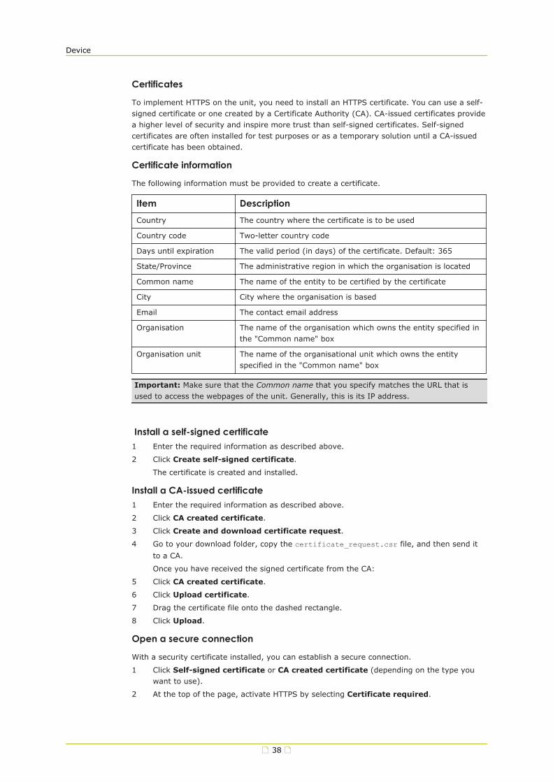
Certificate information
The following information must be provided to create a certificate.
Item DescriptionCountry The country where the certificate is to be used
Country code Two-letter country code
Days until expiration The valid period (in days) of the certificate. Default: 365
State/Province The administrative region in which the organisation is located
Common name The name of the entity to be certified by the certificate
City City where the organisation is based
Email The contact email address
Organisation The name of the organisation which owns the entity specified inthe "Common name" box
Organisation unit The name of the organisational unit which owns the entityspecified in the "Common name" box
Important: Make sure that the Common name that you specify matches the URL that isused to access the webpages of the unit. Generally, this is its IP address.
Install a self-signed certificate1 Enter the required information as described above.
2 Click Create self-signed certificate.
The certificate is created and installed.
Install a CA-issued certificate1 Enter the required information as described above.
2 Click CA created certificate.
3 Click Create and download certificate request.
4 Go to your download folder, copy the certificate_request.csr file, and then send it
to a CA.
Once you have received the signed certificate from the CA:
5 Click CA created certificate.
6 Click Upload certificate.
7 Drag the certificate file onto the dashed rectangle.
8 Click Upload.
Open a secure connection
With a security certificate installed, you can establish a secure connection.
1 Click Self-signed certificate or CA created certificate (depending on the type youwant to use).
2 At the top of the page, activate HTTPS by selecting Certificate required.
Device
38
3 Refresh the page.
4 Log on to the unit.
Your browser is now using a secure connection to communicate with the unit.
10.5 User ManagementInitial setup
Out of the box, the unit is freely accessible - that is, when you connect to the web server youare not prompted to log on. To prevent unauthorised access, we recommend that youimplement user authentication. This is done by creating user accounts and activating userlogin. The number of user accounts you can create is virtually unlimited.
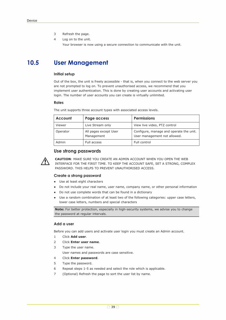
Roles
The unit supports three account types with associated access levels.
Account Page access PermissionsViewer Live Stream only View live video, PTZ control
Operator All pages except UserManagement
Configure, manage and operate the unit.User management not allowed.
Admin Full access Full control
Use strong passwordsCAUTION: MAKE SURE YOU CREATE AN ADMIN ACCOUNT WHEN YOU OPEN THE WEBINTERFACE FOR THE FIRST TIME. TO KEEP THE ACCOUNT SAFE, SET A STRONG, COMPLEXPASSWORD. THIS HELPS TO PREVENT UNAUTHORISED ACCESS.
Create a strong password● Use at least eight characters
● Do not include your real name, user name, company name, or other personal information
● Do not use complete words that can be found in a dictionary
● Use a random combination of at least two of the following categories: upper case letters,lower case letters, numbers and special characters
Note: For better protection, especially in high-security systems, we advise you to changethe password at regular intervals.
Add a user
Before you can add users and activate user login you must create an Admin account.
1 Click Add user.
2 Click Enter user name.
3 Type the user name.
User names and passwords are case sensitive.
4 Click Enter password.
5 Type the password.
6 Repeat steps 1-5 as needed and select the role which is applicable.
7 (Optional) Refresh the page to sort the user list by name.
Device
39
Activate user authentication
Once you have an Admin account, you can activate user authentication for the unit.
● On the User Management page, click Activate user login.
Users will now be prompted to supply their user name and password when they connect tothe unit.
Edit a user
Admins can change user passwords and assign new roles.
1 Click the Password box.
2 Type a new password.
3 Click the Role box.
4 Select a new role.
The user name cannot be modified.
Delete a user
Admins can delete user accounts.
1 Click the check box of the user you wish to delete.
2 Click Delete user.
3 In the information bar, click Yes, delete.
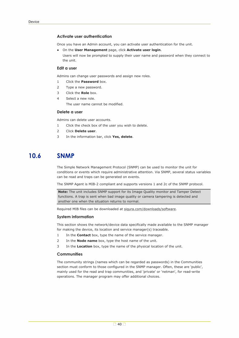
10.6 SNMPThe Simple Network Management Protocol (SNMP) can be used to monitor the unit forconditions or events which require administrative attention. Via SNMP, several status variablescan be read and traps can be generated on events.
The SNMP Agent is MIB-2 compliant and supports versions 1 and 2c of the SNMP protocol.
Note: The unit includes SNMP support for its Image Quality monitor and Tamper Detectfunctions. A trap is sent when bad image quality or camera tampering is detected andanother one when the situation returns to normal.
Required MIB files can be downloaded at siqura.com/downloads/software.
System information
This section shows the network/device data specifically made available to the SNMP managerfor making the device, its location and service manager(s) traceable.
1 In the Contact box, type the name of the service manager.
2 In the Node name box, type the host name of the unit.
3 In the Location box, type the name of the physical location of the unit.
Communities
The community strings (names which can be regarded as passwords) in the Communitiessection must conform to those configured in the SNMP manager. Often, these are 'public',mainly used for the read and trap communities, and 'private' or 'netman', for read-writeoperations. The manager program may offer additional choices.
Device
40

Traps
An alarm status change in the unit generates a trap which can be caught by any SNMPmanager. The unit can, for example, send traps on the occurrence of Image Quality andCamera Tampering events. Variables, which can be read from the unit's MIB through an SNMPmanager, indicate why the alarm occurred. The OPTC-VCA-MIB required for this can bedownloaded, together with the other MIBs for the unit, at siqura.com/downloads/software.
1 In the Version list, click the SNMP version used.
2 In the IP Address box, type the IP address associated with the manager program.
3 In the Port box, type the destination port number.
Default: 162.
Note: Version, IP Address, and Port are required fields.
4 In the Alternate IP Address box, if desired, type an alternative destination IP address.
5 In the Alternate Port box, if desired, type an alternative destination port number.
6 If desired, select Enable to activate Authentication trap.
This adds an authentication trap to catch attempts at access using the wrong communitystring.
Device
41

11 DiagnosticsThe Logging page can assist you when you need to troubleshoot encountered issues.
In This Chapter11.1 Logging............................................................................................................. 42
11.2 LED...................................................................................................................42
11.1 LoggingThe unit includes logging functionality which can be used for diagnostic purposes.
Download a log file
To view the logfile of the unit, you need to download it to your computer.
1 Click Download log file.
2 In your download folder, click system.log.
The file is opened in Notepad.
Use a syslog server
Syslog is a standard which allows devices to send event notification messages over IPnetworks to event message collectors, also known as syslog servers.
1 In the Syslog server IP address box, type the IP address of the syslog server you willbe using.
2 To activate Send log to syslog server, select Enable.
11.2 LEDTo identify the unit you can make the status LED blink for a selectable time span.
Start blinking1 Click to open the Start blinking LED list.
2 Click a time span.
Stop blinking1 Click to open the Start blinking LED list.
2 Click Stop blinking LED.
42

12 AnalyticsSiqura video encoders include video analytics which can monitor the video images and raisean alert when the following events occur:
● The image quality becomes too poor.
● The camera's position or field of view has changed.
● Movement is detected in a predefined area of the image.
In This Chapter12.1 Motion Detection.................................................................................................43
12.2 Tampering..........................................................................................................44
12.3 Quality Monitor................................................................................................... 45
12.1 Motion DetectionMotion detection enables the user to define a portion of the screen and to detect picturechanges there. These changes could be caused by motion or varying lighting, for example.
Set up motion detection
The Motion Detection function enables the unit to trigger an alarm when motion in a specifiedarea of the field of view - that is, the Region of Interest (ROI), reaches or exceeds aconfigured sensitivity threshold value.
1 In the upper-right corner, click Activate Motion Detection.
The button turns green and the Draw ROI button appears.
Drawing a ROI is optional. If you do not need a ROI, proceed to step 4. In that case, theentire field of view becomes the ROI.
2 Click Draw ROI.
3 Drag the mouse pointer across the preview to draw the Region of Interest (ROI).
If the ROI is not the correct size or in the wrong place you can repeat steps 2 and 3.
4 Drag the Alarm level slider to set the sensitivity of the detection.
Local change is only detected if its level exceeds the defined value (indicated by the redhorizontal line). The Alarm level setting can be used to eliminate unwanted ('false')triggering (for example, caused by background noise or constant local movement). Youmay need to try out several alarm levels to achieve the best detection.
5 If required, go to the Event Management page and add an event with motion detectionas an event trigger.
Deactivate motion detection
You can (temporarily) deactivate motion detection.
● Click Deactivate Motion Detection.
The Motion Detection button turns red and the ROI is hidden. Clicking the button onceagain reactivates motion detection using the same ROI.
43

12.2 TamperingAs a result of tampering, or more accidentally, after cleaning, a camera may no longer coverthe area designated for monitoring. The Tampering function can detect camera positionchanges and scene changes such as a blocked camera view. It does so by comparing thecurrent image to one or more reference images that were captured and stored earlier.
Set up tamper detection (EVE encoders)
Tamper detection needs a reference image for comparison with the current image.
1 Click Activate Tamper Detection.
The button turns green and reference image learning starts. Progress is indicated by aprogress bar.
Once created, the reference image is displayed as an overlay over the current image.
Detection starts immediately.
When the camera scene or position is changed, a warning is displayed: "Camera hasbeen tampered with!!!".
2 If required, go to the Events Management page, add an event with a "Camera #tampering detected" trigger, and then define the subsequent action.
3 To delete the current reference image, click Deactivate Tamper Detection.
Clicking Activate Tamper Detection once more will create a new reference image.
Set up tamper detection (S-60/S-64 E v2)
The Tamper Detection function enables the unit to trigger an alarm when camera positionchanges or scene changes are detected in a specified area of the field of view, that is, theRegion of Interest ROI). Tamper detection needs a reference image for comparison with thecurrent image.
1 Click Activate Tamper Detection.
The button turns green and additional buttons appear.
2 If the selected camera is a PTZ camera, click Select to open the PTZ preset list in thelower-left corner, and then click the PTZ preset for which you want to create a referenceimage.
Drawing a ROI is optional. If you do not need a ROI, proceed to step 5. In that case, theentire field of view becomes the ROI.
3 Click Draw ROI.
4 Drag the mouse pointer across the preview to draw the Region of Interest (ROI).
This defines the area which will be monitored for changes.
5 Click Add reference image.
The reference image is created. Progress is indicated by a progress bar.
Once created, the reference image appears as an overlay with a green border.
6 Click Show reference images.
7 Click the new reference image, type a name in the Name box, and then close thedialogue box.
8 To create more reference images, repeat steps 2-7 as needed.
Detection starts immediately.
When the camera scene or position is changed, a warning is displayed: "Camera hasbeen tampered with!!!" and the reference image border goes from green to red.
9 If required, go to the Events Management page (see "Event" on page 25), add an eventwith a "Camera # tampering detected" trigger, and then define the subsequent action.
10 To delete a reference image, click Show reference images, point to the image to bedeleted, and then click the Recycle button.
Analytics
44

12.3 Quality MonitorThe Quality Monitor can detect if images produced by the camera are still usable. Fourcoloured dials give an indication of the performance of the camera and show whether or not itneeds attention. A quality check is made against what is normally a good picture.
Examples of detectable occurrences● The camera is in focus during sunny days, but out of focus in low light situations.
● The initial daytime camera position seemed OK, but streetlights and spot lights affect theimage during nighttime.
● The lens has got dirty.
● The iris control has got stuck.
● Camera failure occurs.
Measurements
The Quality Monitor can measure the contrast level, exposure, SNR (Signal-to-Noise Ratio)and picture detail. The four measurements are enabled by default. The camera health is beingmeasured continuously.
State DescriptionError state
Hysteresis: the area where the alarm output is either"true" or "false" depending on the preceding alarm state
Correct performance
On the Event Management page, you can add events triggered by various image qualitystates, such as "... image too bright", "... contrast too low", or "... detail too low", and thendefine actions to be taken when a specific state occurs.
Analytics
45
13 AdvancedThe Advanced menu gives access to the Direct Streaming, Data, and Audio (if supported)pages.
Important: We recommend that you have in-depth understanding of the Advanced settingsand their values before you make any changes. If in doubt, do not change the defaultvalues.
In This Chapter13.1 Direct Streaming.................................................................................................46
13.2 Data..................................................................................................................47
13.3 Audio.................................................................................................................48
13.4 RTSP................................................................................................................. 48
13.1 Direct StreamingOn the Direct Streaming page you can enter IP settings for direct streaming to a unicast ormulticast IP address.
Multicast
The unit supports IP multicast. This is a method for 'one-to-many' real-time communicationover an IP network. The technique can be used to send media streams from an IP camera or avideo encoder to a group of interested receivers in a single transmission. The intermediarynetwork switches and routers replicate the data packets to reach the multiple receivers on thenetwork. The switches and other network devices used must be carefully configured for, andcapable of handling multicasting and its associated protocols (most notably IGMP).
SAP
The unit includes a SAP announcer. The Session Announcement Protocol (SAP) is used toadvertise that a media stream generated by the unit is available at a specific multicastaddress and port. SAP listening applications can listen to the announcements and use theinformation to construct a guide of all advertised sessions. This guide can be used to selectand start a particular session. The SAP announcer is not aware of the presence or absence ofSAP listeners.
1 In IP address, type the multicast destination IP address for the announcements andmedia streams.
Range: 224.2.128.0 ~ 224.2.255.255.
2 In Port, type the destination port number.
Default: 1024. Use even numbers only.
3 Select Enable.
Session announcements and media streams will now be sent to the given IP address.
The media stream can be identified through the Program name which is made up of thecamera name and stream number.
46

Direct Streaming
The unit supports direct media streaming to a multicast or unicast IP address (a decoder orviewing application, for example).
1 In IP address, type the destination IP address.
2 In Port, type the destination port number.
Default: 50010. Use even numbers only.
3 Select Enable.
Audio and data streaming
Per camera, you can set up direct streaming of audio and data (if supported by the unit).Specify the appropriate destination/source IP addresses and port numbers, and then selectEnable to activate Direct Streaming.
Quad view
On the Quad view tab of the S-64 E v2, you can configure settings for Quad view streamingusing RTSP Multicast or Direct Streaming. Note that Audio, Data, and SAP settings are notavailable. For more information about Quad view streaming, see also Camera > StreamingProfiles > Quad view.
13.2 DataPTZ commands over TCP
The unit supports the streaming of PTZ data over TCP using a client/server connection. TheTCP connection is bidirectional.
1 In the Listening on port box, specify the port on which the server listens for incomingTCP connections.
Range: [0 ... 65535]. Default: 1024.
2 To activate this function, select Enable.
Bit rate
Determines the speed of the digital transmission - that is, the amount of informationtransferred/processed per unit of time.
TX/RX
The TX and RX indicators next to the Bit rate setting are highlighted in green when data istransmitted (TX) or received (RX) via the serial port.
Word length
Determines the number of bits that is transferred in a single operation.
Stop bits
Indicates the end of a data character to enable the receiver to resynchronise with the stream.
Parity mode
Enables the sending of an extra bit with each data character for error detection purposes.
Wire mode
The RX-4xx interface type on the data connector is set in software. Select the required type inthe Wire mode list.
Advanced
47

Biasing
If biasing is needed, it should be enabled on at least one module on the bus.
Termination
Normally, the devices at the two extremes of a bus are terminated, while intermediate devicesare not. Therefore: RS-422, always enable (being point-to-point); RS-485, enable only for thefirst and last module connected to the bus configuration.
13.3 AudioInput select
Settings: Line, Microphone
Profile
Preset combinations of settings.
● PCM 16bit: uncompressed 16-bit audio, sample rate 48 kHz
● PCM 24bit: uncompressed 24-bit audio, sample rate 48 kHz
● G.711 A-law: mainly used in Europe and Australia
● G.711 µ-law: mainly used in USA and Japan
Input gain
Drag the slider to adjust the input gain. Range: 0 ~ 30 dB.
Input level
Graphic bar to indicate the audio input level in dBFS (decibels below full scale).
Output gain
Drag the slider to adjust the output gain. Range: -80 ~ 0 dB.
Output level
Graphic bar to indicate the audio output level in dBFS (decibels below full scale).
13.4 RTSPRTSP Multicast
The unit supports multicast media streaming via the Real-Time Streaming Protocol (RTSP).The RTSP transmitter does not require enabling.
1 In Multicast address, type the destination multicast IP address.
2 In the Port box, type the destination port number.
Default: 50000. Use even numbers only.
Advanced
48

14 TroubleshootingIf you experience problems with your unit the following sections may help you to identify andresolve underlying causes.
In This Chapter14.1 Date & Time issues..............................................................................................49
14.2 FTP issues..........................................................................................................49
14.3 Logon issues.......................................................................................................49
14.4 Network issues................................................................................................... 50
14.5 PTZ issues..........................................................................................................50
14.6 Upgrade issues................................................................................................... 51
14.7 Video issues....................................................................................................... 51
14.8 Webpage issues.................................................................................................. 52
14.1 Date & Time issuesNo time server active!
Cause: Obtain Time server from DHCP is enabled, but on the Network page DHCP isdisabled.
Solution: Open the Network page and enable DHCP or set the Time server addressmanually on the Date & Time page.
Cause: The Time server address is set manually but the address cannot be reached.
Solution: Verify the Time server address. If the address is specified as a name, a DNSserver must be available. Open the Network page and check the Preferred DNS andAlternate DNS addresses.
14.2 FTP issuesUnable to upload to FTP server
Cause: The FTP server does not hold a user account associated with your encoder.
Solution: Request a user account from the FTP server.
14.3 Logon issuesUnable to log on
Cause: Incorrect user name or password. User name and password are case sensitive.
Solution: Supply correct user name and password.
49

Cause: Unknown user.
Solution: Request Administrator to create a user account.
Use the reset button
If you have forgotten your Admin password or are otherwise locked out of your video encoderyou can regain access by using the reset button on the front panel of the unit.
1 Insert a straightened paper clip into the reset button hole which is located:
- to the left of the VIDEO IN BNC connector (EVE ONE).
- below the Digital I/O connector (EVE FOUR).
- to the right of the Digital I/O connector (EVE 4x4).
- to the left of the Digital I/O connector (S-60/S-64 E v2).
2 Keep the reset button depressed for at least three seconds.
This erases the upgrade firmware (if present) in the upgrade image area.
The unit will revert to its factory-set network settings.
3 Use the IP address found on the sticker on the unit to access the webpages.
14.4 Network issuesNo network connection between the unit and the browsing PC
Cause: Physical network issue(s).
Solution: Verify that all network devices are properly connected and powered up. Follow thecables, make sure they are plugged into the correct connectors, and check every connectorthoroughly.
Cause: Network configuration issue(s). To establish an IP connection, the unit and thebrowsing PC must be on the same subnet. EVE encoders request an IP address via DHCP bydefault. If no server is found, the unit reverts to its factory-set IP address in the 10.x.x.xrange. On S-64 E v2 units, DHCP is disabled by default.
Solution: Install Device Manager (available for download at siqura.com/downloads/software)on the browsing PC. Scan the network with Device Manager. If the unit is not detected, setthe network adapter of the PC to the factory-set subnet of the unit. The IP address is printedon a sticker on the unit. Use Device Manager or a browser to access the unit from the PC, andthen modify its network configuration as needed.
Cause: Security issue(s). The connection is blocked by a firewall.
Solution: Check if there is a firewall on the PC or on the network which is blocking theconnection. Contact your system or network administrator for assistance, if necessary.
14.5 PTZ issuesNo PTZ control from Live Stream page
Cause: The connected camera has no PTZ functionality.
Solution: Connect a PTZ camera.
Cause: The active PTZ driver is not compatible with the connected camera.
Solution: On the PTZ page, select a driver which is supported by the camera. Requireddrivers can be uploaded to your video encoder if necessary.
Troubleshooting
50
14.6 Upgrade issuesSuccessful upgrades are reported as "Successfully upgraded to version ...". In the event of anunsuccessful upgrade, the following error messages may help you pinpoint the cause of theproblem.
Upgrade procedure already in progress
Cause: The unit received multiple upgrade requests at approximately the same time.However, only one request can be handled at a time. The later request receives this errormessage.
Solution: Issue one upgrade request at a time and wait for the unit to respond.
Invalid firmware file
Cause: The unit performs a number of checks to determine the validity of the file. If it findsproblems with the file, such as the file not being a firmware file with .sqrfw extension, it
displays this error message.
Solution: Use a firmware file with .sqrfw extension.
Device hardware is incompatible
Cause: If the image identifier of the hardware does not match the image identifier of thefirmware file, this error message indicates that the selected firmware file is not intended forthe unit. In that case, the upgrade procedure is terminated. The fixed image and the upgradeimage stay in the memory of the unit. After a reboot, the unit runs the same image asbefore the reboot.
Solution: Use a firmware file which is compatible with the unit.
Firmware file is corrupt
Cause: The firmware file contains a CRC error. When this error occurs, the unit rebootsautomatically and restarts with the fixed image.
Solution: Download and install usable firmware.
Rule validation failed
Cause: The firmware file is not suitable for this particular device.
Solution: Upgrade with firmware intended for this unit.
Failed to write firmware to flash
Cause: The firmware file is streamed directly into flash. Various errors may occur whilewriting the firmware to flash. There may be connection loss, for example, or a reboot duringthe upgrade procedure. If any such error occurs, the unit reboots automatically and restartswith the fixed image.
Solution: Prevent a loss of connection or a reboot during the upgrade procedure. Do notleave the Device Management page or close your browser.
14.7 Video issuesFrames are being dropped
Cause: On multichannel units, the four encoders can simultaneously handle video encoding atfull frame rate at 960H resolution. It is not recommended, however, to generate eight videostreams at 960H. This may overtax the hardware and lead to frames being dropped.
Troubleshooting
51
Solution: Set a lower resolution for one or more video streams and disable the quad viewstream if not needed.
Frame rate drops
Cause: On multichannel units, the four encoders can simultaneously handle video encoding atfull frame rate at 960H resolution. It is not recommended, however, to generate eight videostreams at 960H. This may overtax the hardware and lead to drops in frame rate (see theactual frame rate measurement).
Solution: Set a lower resolution for one or more video streams and disable the quad viewstream if not needed.
Corrupted video stream, visible smears or stuttering video
Cause: Not all data is received by the receiver due to network congestion.
Solution: Make sure there is enough bandwidth available in the network for the stream to betransported from the camera or encoder to the receiver. You can also reduce any overloadcaused by peak traffic from the encoder. To do this, set the Traffic Shaping to a higher value.See Camera > Streaming Profiles > Stream > Traffic shaping.
14.8 Webpage issuesThe built-in webpages are displayed incorrectly in your web browser
Cause: The unit supports only recent web browser versions.
Solution: Only use the latest two versions of Chrome, Firefox, Internet Explorer or Safari.
Cause: JavaScript is not enabled in your web browser.
Solution: Open the Privacy (or Security settings) of your web browser and enable JavaScript(Active scripting).
Troubleshooting
52

AcknowledgementsOur units use the following Open Source Components / Libraries:
Component/Library URL● Linux Kernel 2.6 - licensed under the GNU
General Public License (GPL), version 2https://www.kernel.org/
● alsa-lib - licensed under the GNU Lesser PublicLicense (LGPL), version 2.1
https://www.kernel.org/
● alsa-utils – licensed under the GNU GeneralPublic License (GPL), version 2
http://alsa-project.org/
● boost - Boost Software License, Version 1.0 http://boost.org/
● BusyBox - licensed under the GNU GeneralPublic License (GPL), version 2
http://busybox.net/
● ethtool – licensed under the GNU GeneralPublic License (GPL), version 2
https://www.kernel.org/pub/software/network/ethtool/
● freetype - Copyright 1996-2002, 2006 DavidTurner, Robert Wilhelm, and Werner Lemberg
http://www.freetype.org/
● ftpd – (c) Copyright 1995-2000 Trolltech AS.Copyright 2001 Arnt Gulbrandsen
● iproute - licensed under the GNU GeneralPublic License (GPL), version 2
http://www.linuxfoundation.org/collaborate/workgroups/networking/iproute2
● libupnp - Copyright (c) 2000-2003 IntelCorporation, Copyright (c) 2005-2006 RémiTurboult, Copyright (c) 2006 Michel Pfeifferand others
http://pupnp.sourceforge.net/
● logrotate - licensed under the GNU GeneralPublic License (GPL), version 2
https://fedorahosted.org/logrotate/
● msntp - (c) Copyright, N.M. Maclaren, (c)Copyright, University of Cambridge
http://www.hpcf.cam.ac.uk/export/
● newlib - Copyright (c) 1994-2009 Red Hat https://sourceware.org/newlib/
● openssl - Copyright (C) 1995-1998 Eric Young,Copyright (c) 1998-2011 The OpenSSL Project
https://www.openssl.org/
Note: The URLs given above are subject to change and can become outdated.
53

IndexAAcknowledgements................................. 53Advanced.............................................. 46Analytics............................................... 43Audio....................................................48
CCamera................................................. 15Camera Management.............................. 15Camera-#............................................. 28Connection Monitor................................. 25
DData..................................................... 47Date & Time...........................................36Date & Time issues................................. 49Device.................................................. 32Device Management................................32Diagnostics............................................42Digital I/O............................................. 26Direct Streaming.................................... 46
EEvent....................................................25Event Management................................. 25
FFTP issues............................................. 49FTP Push............................................... 27
GGet access to the unit............................... 9Get access via Device Manager...................9Get access via UPnP................................10Get access via web browser....................... 9
IImage Quality........................................ 16
LLED...................................................... 42Live Stream........................................... 12Log on to the unit................................... 10Logging.................................................42Logon issues.......................................... 49
MMeet the EVE family..................................7Meet the S-60/64 E v2 family.....................6Motion Detection.................................... 43
NNAS recording........................................30Network................................................ 33Network issues.......................................50
OOverlays................................................17
PPrivacy Mask..........................................24PTZ...................................................... 22PTZ issues............................................. 50
QQuality Monitor.......................................45
RRecording.............................................. 28RTSP.....................................................48
SS-60/S-64 E v2 / EVE Help........................ 5SD Card................................................ 29Security................................................ 37Server settings.......................................30SNMP....................................................40Streaming Profiles.................................. 19
TTampering............................................. 44Troubleshooting......................................49
UUpgrade issues.......................................51User Management...................................39
VVideo issues...........................................51
WWebpage features...................................11
54

Webpage issues......................................52
Index
55