Embed Size (px)
Citation preview

Foundation Engineering
Dr. Priti Maheshwari
Department Of Civil Engineering
Indian Institute Of Technology, Roorkee
Module - 02
Lecture - 04
Lateral Earth Pressure Theories and Retaining Walls – 4
We were discussing about the Retaining Walls, in the last class we discussed about
various types of retaining walls that is gravity walls, semi gravity walls, cantilever walls
and then we talked of counter fort retaining walls. And then we started with that how the
Rankine or Coulombs active earth pressure theory can be applicable to estimate the
lateral earth forces in case of these retaining walls. So, we were discussing about the
Rankine’s theory and retaining walls.
So, let us try to see, that what are the various aspects of this kind of analysis? If you
remember we made an assumption that the failure is taking place at a vertical plane,
which I indicated in the last class as A B. So, various forces, which will be acting on that
particular wall they are Rankine active force.
(Refer Slide Time: 01:25)
That is I am representing by P a Rankine, weight of the soil above heel which is W s and
then weight of the concrete, this concrete weight is from which the wall is made up of
that is W c. You see in this figure how all these three forces they are acting on the wall.

(Refer Slide Time: 01:47)
Since the backfill is inclined and as you know as, we have already discussed in
Rankine’s theory that this Rankine force will be acting parallel to the inclination of the
backfill. So, here it is P a, which is acting at an angle alpha from the horizontal, this is
what is your weight of the soil above the heel that is W s and this wall is made up of
concrete, so the weight of concrete is acting over here. Now, this if H be the vertical
height of the wall, we are considering this H prime, you see here this H prime is the
length of the face A B you can see here in this figure that this A B is H prime.
And then this Pa Rankine is acting at H by 3 from the bottom of the wall, we have
assumed backfill to be frictionless and therefore, cohesion value is equal to 0 you just
have angle of internal friction and unit weight of the soil. And the properties of the soil
which is lying below the slab that is, this base slab they are c 2 and phi 2 they are shear
resistant parameters of that soil and gamma 2 is the unit weight of that soil.
This was in the case of cantilever retaining wall, what happens in case of gravity wall the
situation remaining the same as far as, Rankine’s theory is concerned only three forces
which were acting on the cantilever retaining wall they act on gravity wall also. You can
see here that three forces ((Refer Time: 03:29)), first one is Rankine active force P a
Rankine, weight of soil above heel that is W s and then weight of concrete W c.

(Refer Slide Time: 03:39)
Exactly, on the similar lines earlier it was for cantilever wall now it is for gravity wall.
You can see that in this case also it has been assumed that the soil or the this trial wedge
is failing along this vertical face which is A B, P a is parallel to this acting at a distance
of H prime by 3, where H prime is the length of this face A B. Backfill is frictionless in
this case also, so c 1 is 0 Gamma 1 and phi 1 are the properties of soil whereas, gamma 2
c 2 and phi 2 they are the properties of soil which is lying below the base slab of wall.
(Refer Slide Time: 04:22)

Then if you consider Coulombs theory, this was the case that 2 cases that we discussed
was for where for Rankine’s theory, if you discuss with respect to the Coulombs theory
then there is little difference in the cases. Only two forces will be acting in that case that
is Coulombs active force P a Coulomb and then weight of the wall W c, How it will be
acting that is shown in this figure.
(Refer Slide Time: 04:48)
Since you know that Coulombs theory can take into account wall friction, so you see
here this P a Coulomb will be acting at an angle of delta to the normal drawn to the back
face of the wall. You see this is the back face of the soil, this is the normal drawn to this
particular surface of the wall and then you draw a line, which is making an angle delta
from this normal and that will represent the line of action of P a Coulomb, where delta is
angle of wall friction.
See in this case we are not assuming the failure to occur along a vertical plane that is A B
which was there in earlier case in case of Rankine’s theory. In this case also the backfill
has been assumed to be frictionless c 1 is 0 and so, you are left with gamma 1 and phi 1
as the property of backfill soil however, for the soil which is lying below the base slab of
the wall the properties are phi 2 c 2 and gamma 2.
So, what is the difference between the analysis using Rankine’s theory and Coulombs
theory is that that the Rankine’s theory assume that the failure is taking place along the
vertical face which we represented by line A B in the previous figure. However, in
Coulombs theory no such assumption have been made and this Pa Coulomb that is active
force is directly acting on the face of the wall.
(Refer Slide Time: 06:31)
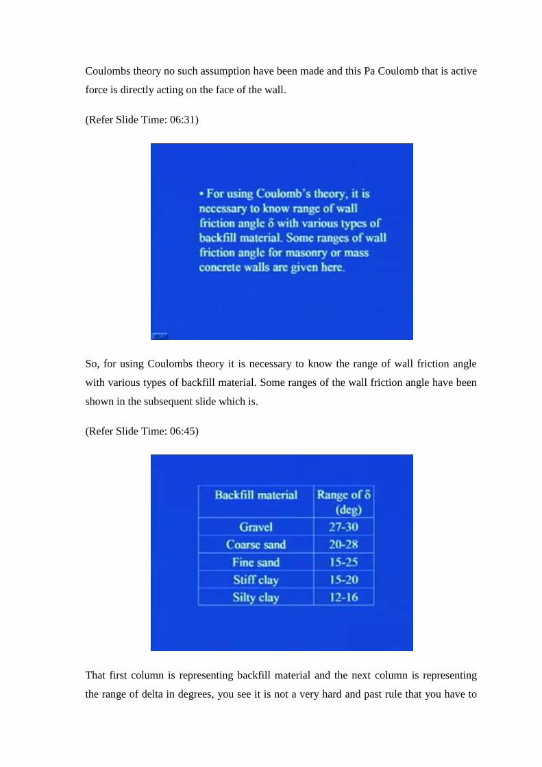
So, for using Coulombs theory it is necessary to know the range of wall friction angle
with various types of backfill material. Some ranges of the wall friction angle have been
shown in the subsequent slide which is.
(Refer Slide Time: 06:45)
That first column is representing backfill material and the next column is representing
the range of delta in degrees, you see it is not a very hard and past rule that you have to

pick any particular value from this has come from the experience. So, in case the backfill
material is gravel in nature then the range of wall friction angle can be of the order of 27
degree to 30 degree whereas, in case of coarse sand it can vary between 20 to 28 degree.
For fine sand it is 15 to 25 degree, for silty clay and stiff clay they it is 12 to 16 degree
and the range for stiff clay is 15 to 20 degrees. So, this gives you rough idea, while you
can decide upon that what should be the value of delta depending on the type of backfill
material. So, backfill material you will be knowing before hand before going for the
construction obviously, that soil you are retaining, so you are knowing about that
particular soil that what type of soil is that.
And then accordingly from these guidelines you can pick the value of delta and go ahead
in the design procedure.
(Refer Slide Time: 08:10)
Now, in case of ordinary retaining walls water table problems and hence hydrostatic
pressure are not encountered. Facilities for drainage from the soils retained are always
provided, why I am mentioning this these points here because, otherwise you will be
wondering that why we are not at all taking into account the presence of or the
probability of the presence of water table in the analysis. We will be discussing how this
drainage takes into account in the wall towards the end of this chapter.

So, for the time being you just remember that right now, we are not taking into account
any hydrostatic pressure which can be present there in practical field. Now, last time we
saw how the proportioning can be done, so once the proportioning is done as I mentioned
you that you have to provide the check for overturning sliding and bearing capacity
failure.
(Refer Slide Time: 09:11)
So, after proportioning the wall a stability of retaining wall is checked the following
steps are to be adopted for this purpose, first is check for overturning about it is toe. See
all the forces which are acting they have some of the forces they have the tendencies to
make the wall overturn above the toe and some of the forces which resist this
overturning. So, we have to identify theses various forces, which are disturbing or which
are resisting and with the help of these forces we should be able to find out that factor of
safety against overturning that we will see in subsequent slides.
The second point is check for sliding failure along the base and then third one is check
for bearing capacity failure of the base. So, let us see one by one, first I will tell you that
how we can provide the check for overturning.

(Refer Slide Time: 10:10)
It has been assumed that Rankine active pressure is acting along a vertical plane A B
drawn through the heel we have seen this already. And your passive pressure you have
already seen it in the few previous lectures, that it is Rankine’s passive pressure and its
magnitude is half K p gamma 2 D square plus 2 c 2 square root of K p into D, where
your D is the depth of placement of base slab of the wall below the ground surface.
(Refer Slide Time: 10:43)
You can see here in this particular figure, that this is the inclined back fill at an
inclination of alpha from the horizontal, this is what is the depth D. So, you see as soon

as, it is the wall will start moving let us say in this direction in due to the presence of this
backfill what will happen that this site of the wall will be moving away from the soil, so
here active conditions will be generated.
However, on the other side of the wall if the moment of the wall is in this direction then
in this area what will happen is the wall will be pushing towards the soil and so, the
passive conditions will be generated and therefore, the passive pressure will be generated
over this much depth. And then you can see that how this active pressure is getting
generated its line of action is parallel to the inclination of this backfill, so you can see
here this is what is your active force which is acting it is having a horizontal component
as Ph and a vertical component as P v.
Again here you see in this area passive condition is developed, so passive pressure will
be developed and subsequently passive force. So, that will be generated in this particular
manner over the depth D, then what will happen since, the wall base slab of the wall has
been placed on the soil, soil will put its reaction on the base of the wall and that reaction
here I am showing by q heel and q toe. It may happen that I mean depending on the type
of the soil this variation here I am assuming is it to be linear variation, but depending on
the type of the soil this variation may or may not be linear, but for the analysis purpose
we assume this to be linear.
So, at heel part I am calling this ordinate to be q heel and at toe part I am calling this
ordinate to be q toe, B is your width of base slab of wall then you see here below the
base slab of the wall your soil properties are gamma 2 phi 2 c 2. However, the backfill
which we have assumed to be frictionless c 1 is equal to 0, so only shear strength
parameter phi 1 will be there in the picture and unit weight of the soil.
And here you see this we we have already assumed that the failure is taking place along
this A B face.Tthe length of this 1 or the depth of the this A B face is H prime and then
this P a will be acting at H by 3 H prime by 3 from the bottom of the wall.

(Refer Slide Time: 13:44)
As I told you gamma 2 is unit weight of the soil in front of heel and under the base slab,
in front of the heel that means, here and below the base slab, so this part is gamma 2 the
unit weight of the soil is gamma 2. K p is Rankine’s passive earth pressure coefficient
which is tan square 45 plus phi by 2, c 2 phi 2 is the cohesion and soil frictional angle
respectively.
Now, how can we take into account the analysis for overturning, as I told you that there
will be some forces which will be trying to overturn the wall along its toe. This is toe this
is heel, so along its toe there will be few forces which will be trying to destabilize the
wall; however, there will be few forces which will be trying to stabilize the wall, let us
try to see one by one.

(Refer Slide Time: 14:44)
That how we can find out these various forces and the moments. The factor of safety
against overturning about the toe that is about point C. (Refer Slide Time: 14:56) You
see here in this one, this is the toe, this is what is the point C, so about this point C we
will check for overturning, this may be expressed as factor of safety overturning is equal
to summation of all the moments which are trying to overturn and then they are the
resisting.
So, these are the resisting moments and this is which will try to make the wall overturn.
So, where your summation M O is sum of moments of forces tending to overturn about
the point C. And summation of M R is the sum of moments of forces tending to resist the
overturning, so before knowing the these moments, first we have to identify that what all
are the forces which are acting on the wall and what is the lever arm of those forces with
respect to the point C.
Once you know the force and its lever arm with respect to point C if you multiply these 2
values you will be getting, the moment about the point C and accordingly, you can go
ahead in the design procedure.

(Refer Slide Time: 16:07)
So, forces which tend to cause overturning about the point C what are they, horizontal
component of Rankine active at earth pressure acting at a distance of H prime by 3 from
the bottom of a base slab.
(Refer Slide Time: 16:20)
Then forces tend to resist overturning about the point c, they are weight of the soil above
heel that is W s, Weight of concrete or masonry W c, Vertical component of Rankine
active force. Then passive force, see the thing is that the amount of or the magnitude of
this passive force is quite small that is why for all the practical purposes it has been

neglected in the analysis obviously, by neglecting this we are committing a mistake
towards safe side that is why we can ignore this particular force.
(Refer Slide Time: 17:04)
Then overturning moment, overturning turning forces just the horizontal component of
the active force which is P h as I showed you in previous slides. So, your summation of
M naught which is equal to Ph into H prime by 3, because Ph is the only force which is
causing overturning about the point C, P h is equal to Pa cos alpha is the horizontal
component of this active force P a.
Now, for calculation of since you have seen that there are many forces which are
resisting the overturning. So, we prepare a sort of table which facilitate the calculation
and clarity, so that table is prepared for the magnitude of force and location of its line of
action, so we prepare the whole thing in a form of a table which makes the thing easier
for us.
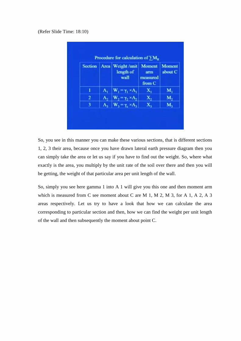
(Refer Slide Time: 18:10)
So, you see in this manner you can make these various sections, that is different sections
1, 2, 3 their area, because once you have drawn lateral earth pressure diagram then you
can simply take the area or let us say if you have to find out the weight. So, where what
exactly is the area, you multiply by the unit rate of the soil over there and then you will
be getting, the weight of that particular area per unit length of the wall.
So, simply you see here gamma 1 into A 1 will give you this one and then moment arm
which is measured from C see moment about C are M 1, M 2, M 3, for A 1, A 2, A 3
areas respectively. Let us try to have a look that how we can calculate the area
corresponding to particular section and then, how we can find the weight per unit length
of the wall and then subsequently the moment about point C.

(Refer Slide Time: 19:07)
If you see here this is a case of gravity retaining wall which I am considering and I have
divided the whole thing into 6 sections, first, Second is this triangular region, third which
is the which is a part of the weight of this wall that is this triangular region, fourth is this
rectangular one, fifth is this triangular one and then sixth is this base area. So, for the
first one knowing this area we can get, the weight per unit length of the wall wal by
multiplying this area to the unit weight of the soil, that is unit weight of the backfill
which is equal to gamma 1.
So, if you see here W 1 is equal to gamma 1 into A 1, A 1 you can find out see this is
trapezoidal kind of thing, so you know this dimension as you have proportioned this
proportioned this wall. And then, you know this dimension you know this height you can
find out this area of the section 1 simply, multiply that by gamma 1 which will give you
the weight of the soil, which is lying in this particular area per unit length of the wall.
Similarly, for this section number 2 this is again the area of the soil, so you take the area
multiply with gamma 1 and you will get the weight of this particular area. You see sec
section number 2 second area and then W 2 is equal to gamma 2 into A 2 then, you see if
I take this triangular area where its line where its will be lying, is here at a distance of
whatever is this distance 1 third of this distance it will be acting right here, so lever arm I
can find out correspondingly.

I know all these dimensions, I know this dimension of the base, I know this and then
further I can add this much amount and I can find out this X 1. So, once I draw this
figure to the scale simply, what I can do I can measure these distances from this point C
and by multiplying this W 1 with this X 1, I can get the value of this moment about C.
Similarly, if I consider this third area let us try to see that what about this third area.
So, you see this third area is the concrete area, so you simply take the area of this
triangular portion you multiply with the unit weight of the concrete, so you will be
getting the weight of the wall of this particular sectional area 3, and then you can get
correspondingly, the lever arm that is at what point its ((Refer Time: 22:11)) will be
lying. So, the weight will weight of this particular area will be acting at that particular
point and you can find out the distance of that point from this point C.
W 3 gamma c into area 3 into X 3, if you multiply W 3 into X 3 you will get this moment
M 3. So, we completed for section 1 section 2 section 3.
(Refer Slide Time: 22:42)
Similarly, for section 4, 5 and 6 we can find out the area you see here section 4 is
rectangular part, it is area we can find out we have already proportioned the thickness of
the stem at the top of the wall. We know this particular height simply, multiply these 2
dimensions you will be getting the area of this part of the wall or area of the section 4
multiply that by gamma of concrete if it is made up of concrete.

If it is made up of stone masonry you have to multiply the gamma of stone masonry, so
accordingly, whatever material that you are using simply multiply the area by the unit
weight of that particular material and that, will result into the weight of the wall of that
particular sectional area. Then its weight will be acting midway of this particular
thickness, so we know this particular width as we have proportioned and then half of this
particular width which will be giving you X 4 that is this one this X 4, you multiply W 4
into X 4, X 4 you will be getting M 4.
Similarly, for area 5 area 6 you can find out correspondingly, W 5 W 6 then X 5 X 6 and
subsequently M 5 M 6 by multiplying W 5 and X 5, and M 6 you can get as W 6 into X
6. Then apart from this weight of the wall and weight of the soil there is vertical
component of active force, which is also resisting this overturning. So, see here I am
adding this particular force or this particular force per unit length of the wall that is P v
and this P v you see here this is what is your P a.
So, its horizontal component is Ph vertical component is P v and this P v will be acting at
a distance of B from this point C. So, its lever arm will be B and if you multiply the
magnitude of this P v by B you will be getting, the moment which will be generated due
to this force P v that I am naming as M v. So, if I sum all the forces or all the this weight
per unit length of the wall plus this P v, so W 1 plus W 2 plus W 3 plus W 4 plus W 5
plus W 6 plus P v this will get result into this particular term, which is summation of C
that is summation all vertical forces.
Why we will require you will realize little later, for the time being just you just
remember that you have to find out the total vertical force. And then the total moment
that is, resisting moment you can get by summing up all the moments that is from M 1 to
M 6 plus M v, this will result into summation of M R which is sum of all the resisting
moment for overturning.
(Refer Slide Time: 26:09)

Where from the table if you see, your P v is the vertical component of active force that is
P a and that you can find out using this expression that is P v is equal to Pa sin alpha.
The moment of force P v about point C is M v, and as I have explained you in the
previous figure that this P v is will be acting at a distance of B from the point C about,
which we are considering the moments of all the forces.
So, this moment due to this P v force will be equal to P v into B which will result into P a
sin alpha into B where your B is width of base slab. So, once this summation of M R is
known using the expression for factor of safety you can evaluate the same.
(Refer Slide Time: 26:59)

Factor of safety how you can do that, you can have a look in this slide, that factor of
safety against overturning is equal to, summation of all the moments which are resisting
the overturning divided by the force which is causing the overturning. So, you see here
M 1 plus M 2 plus M 3 plus M 4 plus M 5 plus M 6 plus M v divided by horizontal
component of active force into H prime by 3, what is the horizontal component of active
force which is equal to P a cos alpha.
So, accordingly here in denominator you have this Pa cos alpha into H prime by 3, the
usual minimum desirable factor of safety with respect to overturning is taken as 2 to 3.
Now, some designers prefer to determine the factor of safety by the following
expression, here you can see that M v is causing the resistance to the overturning. Now,
if I put this M v with a negative sign in the denominator the things are going to be same
because opposite of that M v will be causing overturning.
So, some of the designers they prefer this expression as, they sum all the moment which
are generated due the weight of either soil or weight of the wall. And then they, divide it
by this expression that is P a cos alpha H prime by 3 minus, the moment which is caused
by the vertical component of active force. Now, it was all about the factor of safety
determination of factor of safety against overturning.
Now, what will be the case for sliding along the base, again as if you have seen that.
Factor of safety is always taken the ratio of resisting 1 to the driving 1 that whatever is,
the disturbing force or moment whatever it is.

(Refer Slide Time: 29:11)
So, the factor of safety against sliding may be expressed by the equation that is F S
sliding is F summation of FR prime and then summation of F d, where F R prime is sum
of horizontal resisting forces and F d is sum of horizontal driving forces.
(Refer Slide Time: 29:32)
You see what are the various horizontal forces, because sliding will be taking place as
the horizontal 1 which is above along the base. So, there will be few forces which will be
causing the base to slide over the soil some of the forces they will be resisting it, so the
first one is the horizontal component of this active force which is your P h. Your total

vertical force let us say summation V as you have seen in the earlier slides that I have
mentioned this summation V it is the summation of all the vertical forces then, your P p
that is active force sorry passive force which is acting over this depth D.
So, if the wall is moving towards this 1 this towards this direction then what will happen,
your P h is the force which is causing the wall to slide however, this force Pp which is
against the motion of direction of motion of the wall, so it will be trying to resist the
sliding. Then there will be some friction between this wall and the soil that is this base of
the wall and the soil, so that force I am calling to be R prime.
You can see here the property of the backfill soil is gamma 1 phi 1 C 1 and for this 1 this
soil here that is below the base is gamma 2 phi 2 and C 2. Base of the sorry the base
width is B that is base width of the base slab.
(Refer Slide Time: 31:21)
You see shear strength of soil immediately below the base slab it is represented as s is
equal to sigma tan delta plus c a, where delta is angle of friction between the soil and the
base slab. And c a is the adhesion between soil and base slab and that is the shear
strength which will be acting to resist the sliding.

(Refer Slide Time: 31:51)
So, thus the maximum resisting force that can be derived from soil per unit length of wall
along the bottom of base slab is which I showed you in earlier figure as R prime, that
will be equal to since, s is the shear strength of the soil and that will be providing the
resistance to the wall from sliding. So, that s if you simply multiply that by area of the
cross section then, that will give you the total force.
So, in the longitudinal direction of the wall I am considering unit length, that is why the
area of the cross section on which the shear strength is acting that acting to be, which we
are considering that it is acting on that particular area, that will be your base width
multiplied by the unit length in the longitudinal direction of the wall, so that is B into 1.
So, accordingly as you have seen the expression for s which is sigma tan delta plus c a
simply, substitute this expression over here in this particular expression for R prime, you
will be getting s is equal to B sorry R prime is equal to s into B.
And then s is your sigma tan delta plus ca simply multiply by B in both the terms you
will be getting the magnitude of this force which is resisting the sliding. However, this B
into sigma which is sum of the vertical forces is equal to summation V and therefore,
your R prime will result into summation V tan delta plus B c a, I hope that now you are
able to appreciate for ,that is why we determine the summation of all the vertical forces.
You see once the table is prepared as, I explained you earlier you simply have to pick

that particular value and substitute it here and you will be getting the value of this R
prime directly.
(Refer Slide Time: 33:58)
The passive force is also horizontal resisting force, so that total R prime that is total
resisting force will be equal to the resistance which is offered by the soil which is lying
at the base of the wall, plus the force due to passive pressure that is P p. So, R prime will
result into summation V tan delta plus B into ca plus Pp that is passive force, the only
horizontal driving force, which will tend to slide the wall along the base is horizontal
component of active force P a, which we are representing by P h that is equal to P a into
cos alpha.
Therefore, your summation of F d because this term summation F d you are using in the
expression of factor of safety this will simply, become P a into cos of alpha. So, your
resulting expression for factor of safety will be, that is factor of safety against sliding
along the base that will be.

(Refer Slide Time: 35:08)
Factor of safety against sliding is equal to summation V tan delta plus B c a plus passive
force that is, P p divided by the horizontal component of active force that is Pa cos alpha.
In case of overturning I told you that usually factor of safety between 2 to 3 is adopted
however, in case of factor of safety against sliding along the base this factor of safety of
1.5 is required.
(Refer Slide Time: 35:42)
Now, in many cases the passive force P p is ignored for the calculation of factor of safety
with respect to sliding, and then in general this delta is taken to be some factor of phi 2,

phi 2 is the angle of internal friction of the soil which is lying in front of heel and below
the base slab. So, k 1 is any factor you simply, multiply this factor k 1 to the value of phi
2 and you will be getting the value of delta, that is the angle of friction between the base
slab and the wall.
And the adhesion between the base of the wall base slab of the wall and the soil is equal
to a factor k 2, when you multiply it by the cohesion of the soil which is lying below the
base slab that will result into c a. In most of the cases this k 1 and k 2 are in the range of
half to 2 by 3, so usually either it will be given to you provided by the consultant or
whoever is coming to you for the design of retaining wall, or from your experience
slowly you will get to know that what should be these values, but usually they are to be
taking between the range 1 by 2 to 2 by 3.
So, if you substitute this value of delta and c a in the previous expression of factor of
safety you will result into this expression, that is factor of safety against sliding along the
base of the wall will be equal to summation of V tan of delta. And now, delta I am
substituting by this quantity that is k 1 into phi 2 plus B into c a, c a you substitute here
as k 2 into c 2 plus Pp divided by Pa cos alpha, P a cos alpha is nothing, but the
horizontal component of the active force, which is the driving force for the sliding along
the base of the wall.
(Refer Slide Time: 37:56)

In some instances certain wall may not need a desired factor of safety of 1.5 that is as I
explained you in the previous class, that many a times it may happen that a wall, which is
safe against overturning or it is safe against bearing capacity failure it may happen that it
can fill in sliding. So, in that in case I told you that you have to re-proportion the whole
thing.
Now, the second option which you can adopt such that the wall can become safe against
sliding is that we are going to talk about. So, to increase it is resistance in sliding a base
key may be used I will show you that what exactly do I mean by this base key, it helps in
increasing the passive resistance and as the passive resistance is increasing.
(Refer Slide Time: 38:50)
You can see here, in this expression that as the passive resistance is increasing the factor
of safety value will also increase. And as soon as you achieve the value of 1.5 as factor
of safety against the sliding the your wall you can consider to be safe against sliding
along its base.

(Refer Slide Time: 39:16)
You see here this is a kind of key that is provided, this is additional one, so while your
construction is not that it is an additional unit what happens it is, that the monolithic
construction is done of this particular key with the base slab. So, that the resistance
which is developed due to this should be over this particular depth, you see here with the
presence of this key what will happen is that, when the soil will be pushing towards.
When the wall will be pushing towards the soil, the passive force which is getting
generated only upto a depth of D in the absence of this key will be developed over this
particular depth if the key is provided.
Please, see it again that in case the key is provided the passive force or passive resistance
which is getting generated over this depth D earlier when the key was not present. So, as
soon as this key is introduced this depth get increased to this extent see from here to
here. And once this depth is increased the pressure is increased and simultaneously, if
you find out the area the force will also be increased, and as the passive force is
increased since, it is acting as a resistance against sliding of the base of the wall, your
factor of safety against the sliding is increasing.
So, instead of re-proportioning the wall, let us say there is a case where the wall is safe
against overturning the wall is safe against bearing capacity failure the wall is just failing
in sliding. So, instead of proportioning or re-proportioning the wall and doing all the
steps altogether again we try with this base key and then we check whether by providing

this base key if we are safe or the wall is safe against sliding or not. Some of the key
points related to this aspect, because it is a very important aspect that you must keep in
your mind.
(Refer Slide Time: 41:46)
So, let us try to put in words and some the these are some of the points related to this, the
passive force at the toe without the key is you see the passive force in case the key is not
present, the passive force is getting generated over this depth D only. So, the expression
for passive force is half K p gamma 2 D square plus 2 c 2 square root of K p into D.
Now, the if the key is included the passive force will become, you see here if the this 1 is
introduced what will happen, the passive force will be generated over this step.
Let us say that I am calling this step to be D 1, so in that case your passive force will
become half K p gamma 2 D 1 square plus 2 c 2 square root of K p into D 1. Where Kp
is tan square 45 plus phi by 2 phi 2 by 2, where phi 2 is the angle of friction of the soil
which is lying below the base slab and in front of heel. Since with the inclusion of this
base key the depth is getting increased.

(Refer Slide Time: 43:05)
That is in all the possibility or in all the cases your D 1 is going to be always greater than
D, so as D 1 is greater than D a key obviously, help in increasing the passive resistance
at the toe and hence the factor of safety against sliding. You have seen that this passive
force comes in the numerator in the expression of factor of safety, so as soon as the this
passive force is getting increased obviously, the factor of safety will get increased.
So, usually the base key is used in constructed below the stem and some main steel is run
into the key this is also termed as shear key. Now, this was all about check for
overturning and check for sliding along the base of the wall, let us try to see the third
one, which is check for bearing capacity failure, some of the points let us first discuss
about that and then we will go into mathematical things about this particular check.

(Refer Slide Time: 44:11)
The vertical pressure as transmitted to the soil by the base slab of the retaining wall that
should be checked against ultimate bearing capacity of the soil. You see how this vertical
pressure which is coming into the picture, the weight of the soil and whatever, let us say
in case the surcharge is present all these will transfer the pressure to the soil. You have
already studied in the shallow foundation that how you can determine the bearing
capacity of the soil, that bearing capacity is a kind of strength of the soil that is that much
load the soil can stand without failing.
So, if the total pressure which is getting transmitted from the wall to the soil, if that is
less than the bearing capacity of the soil, the soil will not fail in the bearing capacity. So,
here the disturbing force is going to be the vertical pressure, which is getting transmitted
from the wall to the soil and the resisting force will be the ultimate bearing capacity of
the soil.
The nature and variation of vertical pressure that is transmitted by base slab into the soil
is maximum and minimum pressure occurs at toe and heel respectively. Now, let us try
to see that how this mechanism takes place.

(Refer Slide Time: 45:48)
This is some of all the vertical forces in which this P v is also coming into picture and
that is why I am not showing this P v separately over here simply, P h which is equal to
Pa into cos alpha that is the horizontal component of active force. The backfill is friction
less, so cohesion is 0 that is c 1 is 0 gamma 1 is the unit weight of the backfill soil phi 1
is angle of friction of this backfill soil.
Then here at heel the pressure which is getting transmitted from, the wall to the soil is
minimum which I am naming as q heel and here it is maximum which is q toe, gamma 2
is the unit weight of the soil which is lying below the base slab and in front of heel. Phi 2
and c 2 they are shear strength parameters of the soil lying below the base slab, in the
absence of any shear key, this wall base of the wall is placed at a depth of D from this
ground surface.
So, you see here again we have to find out that what exactly are the forces and ultimate
capacity of this soil which is lying below the base. So, first of all for that thing we really
need to find out that what exactly is the magnitude of q toe and q heel. So, let us try to
see the steps which are to be followed for the determination of q toe and q heel.

(Refer Slide Time: 47:30)
For that we have some of vertical forces acting on base slabs I have already shown you
table, which was showing the details of all the forces and the moment when we were
finding out the factor of safety against overturning. So, you have this summation of V
already with you, then the total horizontal force you know it is the horizontal component
of this active force, which is the P a and that horizontal component is P a cos of alpha.
Now, let the resultant of these 2 V R, you see here in this place, that is this summation of
V and this P h it is resultant is R, ((Refer Time: 48:14)) which is the vectorial summation
of this summation V and P a cos of alpha. See this arrow I am showing that it is the
vectorial summation.

(Refer Slide Time: 48:27)
Then the net moment of these forces about the point C is, if I call that as M net that will
be equal to summation of all the moment, which are resisting the overturning minus
summation of all the moments which are causing the overturning. In notational form it is
going to be summation M R minus summation M O as written here, and I have already
shown you we once we prepared that table half of the work is done, in that table
summation V was known summation M R was known and summation M O is known.
So, simply you pick all those value from that particular table and here you will be able to
find out this M net. Now, I have to find out the line of action of that resultant also, so let
us say that the line of action of this resultant R, intersect the base slab at E, then this
distance C E will become let us say if I name it to be X bar this will be equal to M net by
summation V.

(Refer Slide Time: 49:37)
So, this C distance you can see in this figure is that this distance that wherever, this
resultant R will be acting at this particular point. You see here this dotted line is coming
vertical down, now if I want to find out it is eccentricity from the centre of the base of
this base slab. So, how I can find out this eccentricity e is that, if I substitute subtract this
C distance from B by 2 then I will be getting this eccentricity e.
(Refer Slide Time: 50:16)
So, you see here the eccentricity of the resultant R it can be expressed as, that is B by 2
minus the distance C E. And then the pressure distribution under the base slab may be

determined by using the simple principles of mechanics of materials. As your q is equal
to summation of V by A plus minus M net y by I now what are all these things,
Summation V you have already seen is the sum of all the vertical forces.
(Refer Slide Time: 50:52)
M net is the moment that you have seen either, you take summation of M R minus
summation of M O or what you can do is you can if you know this value of e you can
find out summation of V into e, I is moment of inertia per unit length of base section,
that is 1 by twelve into 1 into B cube. Why we are taking 1 because in the longitudinal
direction of the wall we are considering the unit length and y value will be that is for
maximum and minimum pressure this value of y will be become B by 2. So, in this
expression we know this, we know this, we know this and this, so we can find out this
value of q, y is your B by 2 for maximum and minimum pressures.

(Refer Slide Time: 51:38)
So, you see here, q maximum which is occurring at toe that is equal to summation of V
by B into 1, that is the area which you are considering plus e into summation of V into B
by 2 divided by I which is equal to 1 by twelve B cube into 1. So, this will result into this
expression that is summation V by B 1 plus 6 e by B similarly, we can find out q
minimum which will be at the heel part of the wall, that is q heel is equal to summation
V upon B 1 minus 6 e upon B.
So, you have seen that how we can find out the value of e and then accordingly we can
calculate the maximum and minimum value of this q. So, you see this is how we can find
out the maximum and minimum pressure at the base of the wall, that is the maximum 1
will be occurring at toe and the minimum 1 will be occurring at heel. Now, what are the
various aspects of the this analysis and how we can complete is this is we are in between
half way, so may be we will be we discussing this in the next class.
So, today what exactly we saw is that, that how you can provide the check for
overturning and sliding once the proportioning is done. And then we saw that what do
you mean by shear key, how it is useful in increasing the value of factor of safety against
sliding along the base. And then we started with the check for bearing capacity failure,
we found out the maximum and minimum pressure at toe and heel respectively, after this
we will be seeing all the aspects in the next class.
Thank you.


![Ep118 Lec11 Optoelectronics[1]](https://img.pdfslide.net/doc/110x75/563db867550346aa9a93659b/ep118-lec11-optoelectronics1.jpg)