Embed Size (px)
Citation preview

W164 N9221 Water Street • P.O. Box 450Menomonee Falls, Wisconsin 53052-0450 U.S.A.
PHONE: 262.251.3800 • 800.558.8744 U.S.A. / CANADAFAX: 262.251.7067 • 800.329.8744 U.S.A. ONLY
www.alto-shaam.com Consult instructions for operation and use.
p r i n t e d i n u . s . a .
R o t i s s e r i eE l e c t r i c
Models: AR-7E
• INSTALLATION
• OPERATION
• MAINTENANCE
MN-28657 (r e v 1 ) • 03/15

MN-28657 (Rev 1) 03/15 • AR-7E Rotisserie • 2
Delivery . . . . . . . . . . . . . . . . . . . . . . . . . . . . . . . . . . 1Unpacking . . . . . . . . . . . . . . . . . . . . . . . . . . . . . . . 1Safety Procedures and Precautions . . . . . . . . . . . . 2
InstallationSite Installation . . . . . . . . . . . . . . . . . . . . . . . . . 3Leveling . . . . . . . . . . . . . . . . . . . . . . . . . . . . . . . 3Clearance Requirements . . . . . . . . . . . . . . . . . . 3Sound Pressure Levels . . . . . . . . . . . . . . . . . . . 3Dimension Drawings . . . . . . . . . . . . . . . . . . . . . 4Product Capacity . . . . . . . . . . . . . . . . . . . . . . . . 4Electrical Connection . . . . . . . . . . . . . . . . . . . . . 5Stacking Combinations & Instructions . . . . . .6-7Drip Tray Installation . . . . . . . . . . . . . . . . . . . . . 8Options & Accessories . . . . . . . . . . . . . . . . . . . 8
Operating InstructionsControl Identification . . . . . . . . . . . . . . . . . . . . . 9Cooking Procedures - Quick Reference . . . . . 10Cooking Instructions . . . . . . . . . . . . . . . . . . . . 11Hold Only Instructions . . . . . . . . . . . . . . . . . . 12Additional Browning Feature . . . . . . . . . . . . . . 13Preset Menu Key Option . . . . . . . . . . . . . . .14-15Product Loading . . . . . . . . . . . . . . . . . . . . .16-17Grease Collection . . . . . . . . . . . . . . . . . . . .18-19
Care and CleaningCleaning and Preventative Maintenance . . . . . 20Protecting Stainless Steel Surfaces . . . . . . . . 20Cleaning Agents . . . . . . . . . . . . . . . . . . . . . . . . 20Cleaning Materials . . . . . . . . . . . . . . . . . . . . . . 20Equipment Care . . . . . . . . . . . . . . . . . . . . . . . . 21Clean Daily . . . . . . . . . . . . . . . . . . . . . . . . . . . . 21Daily Gasket Cleaning . . . . . . . . . . . . . . . . . . . 22Clean Convection Box . . . . . . . . . . . . . . . . . . . 22Check Overall Condition . . . . . . . . . . . . . . . . . 22
ServiceTroubleshooting Guide . . . . . . . . . . . . . . . . . . 23Bulb Replacement Instructions . . . . . . . . . . . . 24Final Floor . . . . . . . . . . . . . . . . . . . . . . . . . . . . 25Final Floor Parts List . . . . . . . . . . . . . . . . . .26-27Full Assembly & Door Assembly . . . . . . . . . . . 28Full Assembly & Door Assembly Parts Lists . . 29Interior View . . . . . . . . . . . . . . . . . . . . . . . . . . . 30Electrical Service . . . . . . . . . . . . . . . . . . . . . . . 31Replacement of Glass Door . . . . . . . . . . . . . . . 32Stainless Steel Back Panel . . . . . . . . . . . . . . . 33Grease Collection Unit . . . . . . . . . . . . . . . . . . . 34
Wire DiagramsAlways refer to the wire diagram(s) included with the unit for most current version.
WarrantyTransportation Damage and Claims . Back CoverLimited Warranty . . . . . . . . . . . . . . . . Back Cover

MN-28657 (Rev 1) 03/15 • AR-7E Rotisserie • 1
DELIVERY
This Alto-Shaam appliance has been thoroughly tested and inspected to ensure only the highest quality unit is provided. Upon receipt, check for any possible shipping damage and report it at once to the delivering carrier. See Transportation Damage and Claims section located in this manual.
This appliance, complete with unattached items and accessories, may have been delivered in one or more packages. Check to ensure that all standard items and options have been received with each model as ordered.
Save all the information and instructions packed with the appliance. Complete and return the warranty card to the factory as soon as possible to ensure prompt service in the event of a warranty parts and labor claim.
This manual must be read and understood by all people using or installing the equipment model. Contact the Alto-Shaam Tech Team Service Department if you have any questions concerning installation, operation, or maintenance.
NOTE: All claims for warranty must include the full model number and serial number of the unit.
UNPACKING
• Carefully remove the appliance from the carton or crate.
NOTE: Do not discard the carton and other packaging material until you have inspected the unit for hidden damage and tested it for proper operation.
• Read all instructions in this manual carefully before initiating the installation of this appliance, using the appliance or performing routine maintenance. Following procedures other than those indicated in this guide to use and clean the appliance is considered inappropriate and may cause damage, injury or fatal accidents, in addition to invalidating the guarantee and relieving Alto-Shaam of all liability.
• DO NOT DISCARD THIS MANUAL. This manual is considered to be part of the appliance and is to be provided to the owner or manager of the business or to the person responsible for training operators. Additional manuals are available from the Alto-Shaam Tech Team Service Department.
• Remove all protective plastic film, packaging materials, and accessories from the appliance before connecting electrical power. Store any accessories in a convenient place for future use.
®
®

MN-28657 (Rev 1) 03/15 • AR-7E Rotisserie • 2
CAUTIONUsed to indicate the presence of a hazard that can or will cause minor personal injury, property damage, or a potential unsafe practice if the warning included with this symbol is ignored.
CAUTIONUsed to indicate the presence of a hazard that can or will cause minor or moderate personal injury or property damage if the warning included with this symbol is ignored.
DANGERUsed to indicate the presence of a hazard that WILL cause severe personal injury, death, or substantial property damage if the warning included with this symbol is ignored.
WARNINGUsed to indicate the presence of a hazard that CAN cause personal injury, possible death, or major property damage if the warning included with this symbol is ignored.
• This appliance is intended to cook, hold or process foods for the purpose of human consumption. No other use for this appliance is authorized and is therefore considered dangerous. The appliance must not be used to cook food containing flammable materials (such as food with alcohol). Substances with a low flash point can ignite spontaneously and become a fire risk.
• This appliance is intended for use in commercial establishments where all operators are familiar with the purpose, limitations, and associated hazards of this appliance. Operating instructions and warnings must be read and understood by all operators and users. We recommend regular training of your staff to avoid the risk of accident or damage to the unit. Operators must also receive regular safety instructions.
• Any troubleshooting guides, component views, and parts lists included in this manual are for general reference only and are intended for use by qualified and trained technicians.
• This manual should be considered a permanent part of this appliance. This manual and all supplied instructions, diagrams, schematics, parts lists, notices, and labels must remain with the appliance if the item is sold or moved to another location.
NOTE: Used to notify personnel of installation, operation, or maintenance information that is important but not hazard related.
SAFETY PROCEDURESAND PRECAUTIONS
Knowledge of proper procedures is essential to the safe operation of electrically and/or gas energized equipment. In accordance with generally accepted product safety labeling guidelines for potential hazards, the following signal words and symbols may be used throughout this manual.
Used to indicate that referral to operating instructions is a mandatory action. If not followed the operator could suffer personal injury.
Used to indicate that referral to operating instructions is recommended to understand operation of equipment.
NOTEFor equipment delivered for use in any location regulated by the following directive:DO NOT DISPOSE OF ELECTRICAL OR ELECTRONIC EQUIPMENT WITH OTHER MUNICIPAL WASTE.
ENVIRONMENTAL CONDITIONS
• Operational Environmental Conditions• Unit must acclimate to room temperature in the
environment it is placed. 24 hours is recommended.• Ambient temperature range of 50° to 110°F (10° to 43°C).• Relative humidity of less than 95% non-condensation.• Atmospheric pressure range of 50KPa to 106KPa.
MN-28657 (Rev 1) 03/15 • AR-7E Rotisserie • 3
INSTALLATION
S ITE INSTALLATION
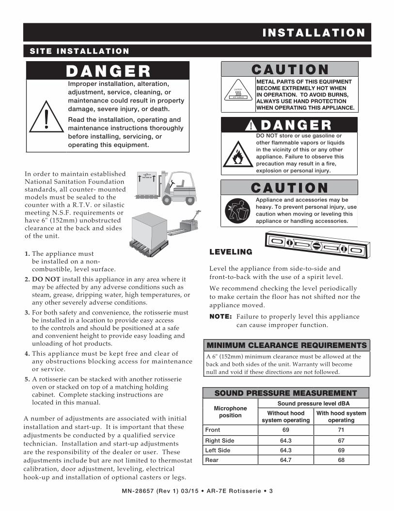
In order to maintain established National Sanitation Foundation standards, all counter- mounted models must be sealed to the counter with a R.T.V. or silastic meeting N.S.F. requirements or have 6" (152mm) unobstructed clearance at the back and sides of the unit.
1. The appliance must be installed on a non-combustible, level surface.
2. DO NOT install this appliance in any area where it may be affected by any adverse conditions such as steam, grease, dripping water, high temperatures, or any other severely adverse conditions.
3. For both safety and convenience, the rotisserie must be installed in a location to provide easy access to the controls and should be positioned at a safe and convenient height to provide easy loading and unloading of hot products.
4. This appliance must be kept free and clear of any obstructions blocking access for maintenance or service.
5. A rotisserie can be stacked with another rotisserie oven or stacked on top of a matching holding cabinet. Complete stacking instructions are located in this manual.
®
LEVELING
Level the appliance from side-to-side and front-to-back with the use of a spirit level.
We recommend checking the level periodically to make certain the floor has not shifted nor the appliance moved.
NOTE: Failure to properly level this appliance can cause improper function.
DANGERImproper installation, alteration, adjustment, service, cleaning, or maintenance could result in property damage, severe injury, or death.
Read the installation, operating and maintenance instructions thoroughly before installing, servicing, or operating this equipment.
DANGERDO NOT store or use gasoline or other flammable vapors or liquids in the vicinity of this or any other appliance. Failure to observe this precaution may result in a fire, explosion or personal injury.
CAUTIONMETAL PARTS OF THIS EQUIPMENT BECOME EXTREMELY HOT WHEN IN OPERATION. TO AVOID BURNS, ALWAYS USE HAND PROTECTION WHEN OPERATING THIS APPLIANCE.
CAUTIONAppliance and accessories may be heavy. To prevent personal injury, use caution when moving or leveling this appliance or handling accessories.
MINIMUM CLEARANCE REQUIREMENTSA 6" (152mm) minimum clearance must be allowed at the back and both sides of the unit. Warranty will become null and void if these directions are not followed.
A number of adjustments are associated with initial installation and start-up. It is important that these adjustments be conducted by a qualified service technician. Installation and start-up adjustments are the responsibility of the dealer or user. These adjustments include but are not limited to thermostat calibration, door adjustment, leveling, electrical hook-up and installation of optional casters or legs.
SOUND PRESSURE MEASUREMENT
Microphone position
Sound pressure level dBAWithout hood
system operatingWith hood system
operatingFront 69 71
Right Side 64.3 67
Left Side 64.3 69
Rear 64.7 68

MN-28657 (Rev 1) 03/15 • AR-7E Rotisserie • 4
INSTALLATION
S ITE INSTALLATION
20-5/16"(516mm)
25-7/16" (646mm)
40-3
/16"
(10
20m
m)
38-3
/16"
(97
0mm
)
4" (
102m
m)
38-1/16" (966mm)
39-1/16" (992mm)
34-3
/16"
(86
8mm
)
36-1
/4"
(920
mm
)
40-1
/4"
(102
2mm
)
38-3
/16"
(97
0mm
)
32-3/8" (823mm)
34-1
/2" (
876m
m)
WIT
H P
AS
S-T
HR
OU
GH
OP
TIO
N
PASS-THROUGH OPTION
32" (
813m
m)
WIT
H S
OLI
D B
AC
K
CL
Ele
ctric
al C
onne
ctio
non
sid
e at
bas
e of
uni
t
62" (
1575
mm
) W
ITH
PA
SS
-TH
RO
UG
H O
PT
ION
61-3
/16"
(155
4mm
) W
ITH
PA
SS
-TH
RO
UG
H O
PT
ION
58-1
1/16
" (14
91m
m)
WIT
H S
OLI
D B
AC
K
88-1
/8" (
2252
mm
) W
ITH
PA
SS
-TH
RO
UG
H O
PT
ION
PASS-THROUGH OPTION
CL
Ele
ctric
al C
onne
ctio
non
sid
e at
bas
e of
uni
t
33-1
5/16
" (86
3mm
)W
ITH
PA
SS
-TH
RO
UG
H O
PT
ION
32-1
/8" (
815m
m)
WIT
H S
OLI
D B
AC
K
61-9
/16"
(156
3mm
) W
ITH
PA
SS
-TH
RO
UG
H O
PT
ION
60" (
1524
mm
) W
ITH
PA
SS
-TH
RO
UG
H O
PT
ION
58-1
/8" (
1477
mm
) W
ITH
SO
LID
BA
CK
87-9
/16"
(222
5mm
) W
ITH
PA
SS
-TH
RO
UG
H O
PT
ION
ElectricalConnection
CORD LENGTH (no plug): 6-1/2' (1,981mm)
single pane flat glass doordouble pane curved glass door
20-5/16"(516mm)
25-7/16" (646mm)
40-3
/16"
(10
20m
m)
38-3
/16"
(97
0mm
)
4" (
102m
m)
38-1/16" (966mm)
39-1/16" (992mm)
34-3
/16"
(86
8mm
)
36-1
/4"
(920
mm
)
40-1
/4"
(102
2mm
)
38-3
/16"
(97
0mm
)
32-3/8" (823mm)
34-1
/2" (
876m
m)
WIT
H P
AS
S-T
HR
OU
GH
OP
TIO
N
PASS-THROUGH OPTION
32" (
813m
m)
WIT
H S
OLI
D B
AC
K
CL
Ele
ctric
al C
onne
ctio
non
sid
e at
bas
e of
uni
t
62" (
1575
mm
) W
ITH
PA
SS
-TH
RO
UG
H O
PT
ION
61-3
/16"
(155
4mm
) W
ITH
PA
SS
-TH
RO
UG
H O
PT
ION
58-1
1/16
" (14
91m
m)
WIT
H S
OLI
D B
AC
K
88-1
/8" (
2252
mm
) W
ITH
PA
SS
-TH
RO
UG
H O
PT
ION
PASS-THROUGH OPTION
CL
Ele
ctric
al C
onne
ctio
non
sid
e at
bas
e of
uni
t
33-1
5/16
" (86
3mm
)W
ITH
PA
SS
-TH
RO
UG
H O
PT
ION
32-1
/8" (
815m
m)
WIT
H S
OLI
D B
AC
K
61-9
/16"
(156
3mm
) W
ITH
PA
SS
-TH
RO
UG
H O
PT
ION
60" (
1524
mm
) W
ITH
PA
SS
-TH
RO
UG
H O
PT
ION
58-1
/8" (
1477
mm
) W
ITH
SO
LID
BA
CK
87-9
/16"
(222
5mm
) W
ITH
PA
SS
-TH
RO
UG
H O
PT
ION
ElectricalConnection
CORD LENGTH (no plug): 6-1/2' (1,981mm)
side view - solid backfront view
20-5/16"(516mm)
25-7/16" (646mm)
40-3
/16"
(10
20m
m)
38-3
/16"
(97
0mm
)
4" (
102m
m)
38-1/16" (966mm)
39-1/16" (992mm)
34-3
/16"
(86
8mm
)
36-1
/4"
(920
mm
)
40-1
/4"
(102
2mm
)
38-3
/16"
(97
0mm
)
32-3/8" (823mm)
34-1
/2" (
876m
m)
WIT
H P
AS
S-T
HR
OU
GH
OP
TIO
N
PASS-THROUGH OPTION
32" (
813m
m)
WIT
H S
OLI
D B
AC
K
CL
Ele
ctric
al C
onne
ctio
non
sid
e at
bas
e of
uni
t
62" (
1575
mm
) W
ITH
PA
SS
-TH
RO
UG
H O
PT
ION
61-3
/16"
(155
4mm
) W
ITH
PA
SS
-TH
RO
UG
H O
PT
ION
58-1
1/16
" (14
91m
m)
WIT
H S
OLI
D B
AC
K
88-1
/8" (
2252
mm
) W
ITH
PA
SS
-TH
RO
UG
H O
PT
ION
PASS-THROUGH OPTION
CL
Ele
ctric
al C
onne
ctio
non
sid
e at
bas
e of
uni
t
33-1
5/16
" (86
3mm
)W
ITH
PA
SS
-TH
RO
UG
H O
PT
ION
32-1
/8" (
815m
m)
WIT
H S
OLI
D B
AC
K
61-9
/16"
(156
3mm
) W
ITH
PA
SS
-TH
RO
UG
H O
PT
ION
60" (
1524
mm
) W
ITH
PA
SS
-TH
RO
UG
H O
PT
ION
58-1
/8" (
1477
mm
) W
ITH
SO
LID
BA
CK
87-9
/16"
(222
5mm
) W
ITH
PA
SS
-TH
RO
UG
H O
PT
ION
ElectricalConnection
CORD LENGTH (no plug): 6-1/2' (1,981mm)
PRODUCT\PAN CAPACITY
98 lb (44 kg) MAXIMUM
ANGLED SPITS (STANDARD): (UP TO 7 SPITS CAN BE USED) Up to twenty-one (21) 3-1/2 lb chickens (1,6 kg) Up to twenty-eight (28) 2-1/2 to 3 lb chickens (1,1 to 1,4 kg)
PIERCING SPITS (OPTIONAL): (UP TO 7 SPITS CAN BE USED) Up to twenty-eight (28) 2-1/2 to 3-1/2 lb chickens (1,1 to 1,6 kg)
TURKEY SPIT (OPTIONAL): (UP TO 3 SPITS CAN BE USED) One (1) Turkey up to 25 lb (11 kg) on each spit

MN-28657 (Rev 1) 03/15 • AR-7E Rotisserie • 5
INSTALLATION
The appliance must be installed by a qualified service technician. The oven must be properly grounded in accordance with the National Electrical Code and applicable local codes.
Plug the unit into a properly grounded receptacle ONLY, positioning the unit so that the plug is easily accessible in case of an emergency. Arcing will occur when connecting or disconnecting the unit unless all controls are in the “off” position.Proper receptacle or outlet configuration or permanent wiring for this unit must be installed by a licensed electrician in accordance with applicable local electrical codes.After wiring and power connection has been completed, turn the main power switch to the “on” position. The main power switch can be left “on” for daily use, but should be turned “off” when cleaning or performing maintenance or repairs to the rotisserie.
ELECTRICAL CONNECTION
DANGERThis appliance MUST be adequately grounded in accordance with local electrical codes or, in the absence of local codes, with the current edition of the National Electrical Code ANSI/NFPA No. 70. In Canada, all electrical connections are to be made in accordance with CSA C22.1, Canadian Electrical Code Part 1 or local codes.
Failure to observe this precaution may damage the appliance, result in electrical shock, fire or personal injury.
DANGEREnsure power source matches voltage identified on appliance rating tag. The rating tag provides essential technical information required for any appliance installation, maintenance or repairs. Do not remove, damage or modify the rating tag.
DANGERAppliances with no cord provided by factory must be equipped with a cord of sufficient length to permit the appliance to be moved for cleaning.
Electrical connections must be made by a qualified service technician in accordance with applicable electrical codes. Use the correct AWG wire size based on the electrical requirements for the appliance.
Failure to observe this precaution may result in electrical shock, damage to the appliance, fire, property damage or personal injury.
ELECTRICAL
VOLTAGE PHASE CYCLE/HZ AMPS kW
208 1 60 40.0 8.3 BARE END, NO PLUG
240 1 60 38.0 8.8 BARE END, NO PLUG
208 3 60 33.0/ph 8.3 BARE END, NO PLUG
240 3 60 32.0/ph 8.8 BARE END, NO PLUG
380-415 3 50/60 24.0/ph 8.8 NO CORD NO PLUG
380 3 50/60 22.0/ph 7.4 415 3 50/60 24.0/ph 8.8
NOTE: Where local codes and CE regulatory requirements apply, appliances must be connected to an electrical circuit that is protected by an external GFCI outlet.
Hard wired models:Hard wired models must be equipped with a country certified external allpole disconnection switch with sufficient contact separation.If a power cord is used for the connection of the product an oil resistant cord like H05RN or H07RN or equivalent must be used.
Power Cord Connection: The side connection is recommended for all applications. If a bottom connection is necessary for counter top units, user will need to provide a cutout in the countertop to allow the cord to hang freely without crimping.
REGARDING INTERNATIONAL STANDARD UNITS:
If the unit is not equipped with flexible cord with plug, an all-pole country approved disconnection device which has a contact separation of at least 3mm in all poles must be incorporated in the fixed wiring for disconnection. When using a cord without a plug, the green/yellow conductor shall be connected to the terminal which is marked with the ground symbol. If a plug is used, the socket outlet must be easily accessible. If the power cord needs replacement, use a similar one obtained from the distributor.
Wire diagrams are located in the inside access panel of the unit.
“WARNING” RISK OF FIRE!Use a UL Listed grounding type plug rated 250 Volts, 50 Amperes, 1 Phase, 3 wire for single phase units and 250 V, 50 A, 3 Phase, 4 wire for three phase units. Plug to be selected and installed only by qualified service personnel. Individual conductors are marked L1, L2, L3 when applicable, N when applicable, and G.
For CE approved units: To prevent an electrical shock hazard between the appliance and other appliances or metal parts in close vicinity, an equalization-bonding stud is provided. An equalization bonding lead must be connected to this stud and the other appliances/metal parts to provide sufficient protection against potential difference. The terminal is marked with the following symbol.

MN-28657 (Rev 1) 03/15 • AR-7E Rotisserie • 6
INSTALLATION
STACKING INSTRUCTIONS
A rotisserie can be stacked with another rotisserie or can be stacked on top of a matching holding cabinet or a convection oven.Stacking hardware is required for all stacking combinations (see above and the options list on pg 8 for more information).All fastening holes have been pre-punched. The stacking combination also requires the minimum clearance of 6" (152mm) at the top, back and both sides.NOTE: Do note remove corner panels. They are not
shown in the drawing only to increase visibility of the interior components.
1. Remove the access panels of both units. 2. 208-240V, 1PH - RH/LH DOOR SWING: Remove power cord, strain relief bushing, and
strain relief washer (drill out 2 rivets) from the rotisserie intended to be on the top. Discard power cord.
208-240V, 3PH - RH/LH DOOR SWING: Remove power cord and strain relief bushing
from the rotisserie intended to be on the top. Discard power cord.
380-415V - RH/LH DOOR SWING: Remove strain relief bushing from the rotisserie
intended to be on the top.
3. Attach cover plate (1010464) to cord hole with 2 rivets. 4. Remove any existing legs or casters from both of
the rotisseries. 5. Review “stacking combinations & installation
requirements” above, then attach support brackets and legs or casters to the rotisseries intended to be on the bottom with 1" (25mm) screws, washers, and lock washers.
6. Punch out the knock out holes A, B, C, & D. 7. Detach decorative exhaust by removing 6 screws from
top panel of rotisserie intended to be on the bottom. 8. Remove 4 plugs (E) from top panel of rotisserie
intended to be on the bottom. 9. Apply high temp silicone around perimeter of
exhaust opening on the top panel of the rotisserie to be on bottom (F).
10. Carefully lift and place the upper unit into position aligning on the bottom unit.
11. Secure units together by inserting a hex head screw and a flat washer in each hole of the top unit and a flat washer, lock washer, and hex nut inside the bottom unit. Securely tighten all four screws.
12. Apply high-temp silicone to seal where the lower weldment attaches to the bottom panel (H).
STACKING COMBINATIONS & INSTALLATION REQUIREMENTS
CAUTIONSTACKING APPLICATIONS OUTSIDE THE U.S. REQUIRE FLANGED FEET AND MUST BE BOLTED TO THE FLOOR.
CAUTIONMAKE CERTAIN TO FASTEN
EACH OF THE FOUR HOLES
STACKING COMBINATIONS (FACTORY INSTALLED) AR-7E rotisserie over AR-7E rotisserie
Requires 6" (152mm) leg assembly 5001414 or 5" (127mm) casters 4007 and stacking assembly (5009981, 5009982, 5009983, 5010355, 5010356, or 5010357 - depending on voltage and door swing - see pg 8) for applications within the United States. Applications outside the U.S. requires 6" (152mm) legs with flanged feet 5001761 bolted to the floor.
[OVERALL HEIGHT: 76-7/8" (1953mm)]
AR-7E rotisserie over AR-7H companion holding cabinet
Requires 6" (152mm) leg assembly 5001414 or 5" (127mm) casters 4007 and stacking assembly (5008787, 5008948 or 5008922 - depending on voltage - see pg 8) for applications within the United States. Applications outside the U.S. requires 6" (152mm) legs with flanged feet 5001761 bolted to the floor.
[OVERALL HEIGHT: 76-7/8" (1953mm)]
AR-7E rotisserie over ASC-4E convection oven
Requires 6" (152mm) legs with flanged feet 5003795 bolted to the floor.
[OVERALL HEIGHT: 79-5/8" (2022mm)]
MN-28657 (Rev 1) 03/15 • AR-7E Rotisserie • 7
INSTALLATION
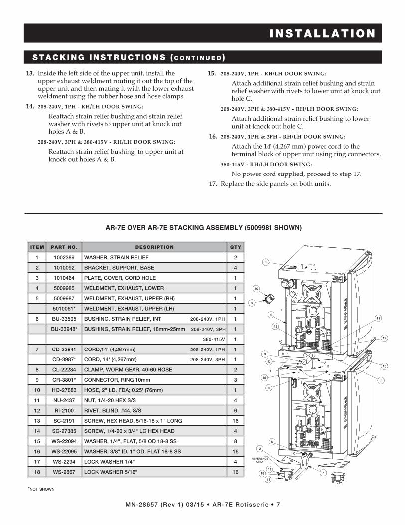
13. Inside the left side of the upper unit, install the upper exhaust weldment routing it out the top of the upper unit and then mating it with the lower exhaust weldment using the rubber hose and hose clamps.
14. 208-240V, 1PH - RH/LH DOOR SWING:Reattach strain relief bushing and strain relief washer with rivets to upper unit at knock out holes A & B.
208-240V, 3PH & 380-415V - RH/LH DOOR SWING:
Reattach strain relief bushing to upper unit at knock out holes A & B.
15. 208-240V, 1PH - RH/LH DOOR SWING:Attach additional strain relief bushing and strain relief washer with rivets to lower unit at knock out hole C.
208-240V, 3PH & 380-415V - RH/LH DOOR SWING:
Attach additional strain relief bushing to lower unit at knock out hole C.
16. 208-240V, 1PH & 3PH - RH/LH DOOR SWING:Attach the 14' (4,267 mm) power cord to the terminal block of upper unit using ring connectors.
380-415V - RH/LH DOOR SWING:
No power cord supplied, proceed to step 17. 17. Replace the side panels on both units.
STACKING INSTRUCTIONS ( c o n t i n u e d )
4
10
8
5
6
12
3
2
13
1816
B
E
A
D
C
F
12
1
11
17
15
15
14
H
7
ITEM PART NO. DESCRIPTION QTY
1 1002389 WASHER, STRAIN RELIEF 2
2 1010092 BRACKET, SUPPORT, BASE 4
3 1010464 PLATE, COVER, CORD HOLE 1
4 5009985 WELDMENT, EXHAUST, LOWER 1
5 5009987 WELDMENT, EXHAUST, UPPER (RH) 1
5010061* WELDMENT, EXHAUST, UPPER (LH) 1
6 BU-33505 BUSHING, STRAIN RELIEF, INT 208-240v, 1PH 1
BU-33948* BUSHING, STRAIN RELIEF, 18mm-25mm 208-240v, 3PH 1
380-415v 1
7 CD-33841 CORD,14' (4,267mm) 208-240v, 1PH 1
CD-3987* CORD, 14' (4,267mm) 208-240v, 3PH 1
8 CL-22234 CLAMP, WORM GEAR, 40-60 HOSE 2
9 CR-3801* CONNECTOR, RING 10mm 3
10 HO-27883 HOSE, 2" I.D. FDA; 0 .25' (76mm) 1
11 NU-2437 NUT, 1/4-20 HEX S/S 4
12 RI-2100 RIVET, BLIND, #44, S/S 6
13 SC-2191 SCREW, HEX HEAD, 5/16-18 x 1" LONG 16
14 SC-27385 SCREW, 1/4-20 x 3/4" LG HEX HEAD 4
15 WS-22094 WASHER, 1/4", FLAT, 5/8 OD 18-8 SS 8
16 WS-22095 WASHER, 3/8" ID, 1" OD, FLAT 18-8 SS 16
17 WS-2294 LOCK WASHER 1/4" 4
18 WS-2867 LOCK WASHER 5/16" 16
referenceonly
AR-7E OVER AR-7E STACKING ASSEMBLY (5009981 SHOWN)
*Not sHowN
MN-28657 (Rev 1) 03/15 • AR-7E Rotisserie • 8
INSTALLATION
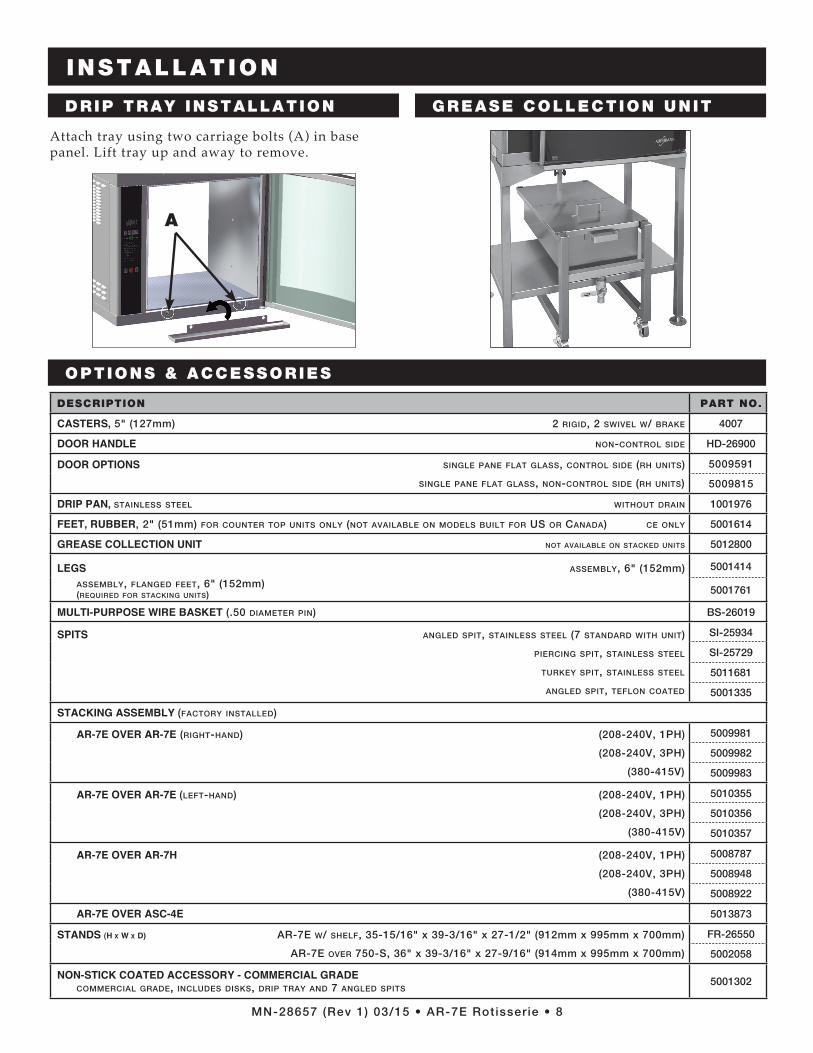
Attach tray using two carriage bolts (A) in base panel. Lift tray up and away to remove.
DRIP TRAY INSTALLATION
A
GREASE COLLECTION UNIT
DESCRIPTION PART NO.
CASTERS, 5" (127mm) 2 rigid, 2 swivel w/ brake 4007
DOOR HANDLE non-control side HD-26900
DOOR OPTIONS siNgle PaNe flat glass, coNtrol side (rH uNits)
siNgle PaNe flat glass, NoN-coNtrol side (rH uNits)
5009591
5009815
DRIP PAN, staiNless steel witHout draiN 1001976
FEET, RUBBER, 2" (51mm) for couNter toP uNits oNly (Not available oN Models built for us or caNada) ce oNly 5001614
GREASE COLLECTION UNIT Not available oN stacked uNits 5012800
LEGS asseMbly, 6" (152mm) asseMbly, flaNged feet, 6" (152mm) (required for stackiNg uNits)
5001414
5001761
MULTI-PURPOSE WIRE BASKET (.50 diaMeter PiN) BS-26019
SPITS aNgled sPit, staiNless steel (7 staNdard witH uNit)
PierciNg sPit, staiNless steel
turkey sPit, staiNless steel
aNgled sPit, tefloN coated
SI-25934
SI-25729
5011681
5001335
STACKING ASSEMBLY (factory iNstalled)
AR-7E OVER AR-7E (rigHt-HaNd) (208-240v, 1PH)
(208-240v, 3PH)
(380-415v)
5009981
5009982
5009983
AR-7E OVER AR-7E (left-HaNd) (208-240v, 1PH)
(208-240v, 3PH)
(380-415v)
5010355
5010356
5010357
AR-7E OVER AR-7H (208-240v, 1PH)
(208-240v, 3PH)
(380-415v)
5008787
5008948
5008922
AR-7E OVER ASC-4E 5013873
STANDS (H x W x D) ar-7e w/ sHelf, 35-15/16" x 39-3/16" x 27-1/2" (912mm x 995mm x 700mm)
ar-7e over 750-s, 36" x 39-3/16" x 27-9/16" (914mm x 995mm x 700mm)
FR-26550
5002058
NON-STICK COATED ACCESSORY - COMMERCIAL GRADE coMMercial grade, iNcludes disks, driP tray aNd 7 aNgled sPits
5001302
OPTIONS & ACCESSORIES

OPERATING INSTRUCTIONS
MN-28657 (Rev 1) 03/15 • AR-7E Rotisserie • 9
ROTISSERIE CONTROL
IDENTIFICATION Cook Cycle Indicator Bar
Preheat Indicator Bar
Cook Time Indicator Bar 1 Cook Time Indicator Bar 2
� FOR 2-STEP COOKING TIME
Cook Temperature Indicator Bar 1Cook Temperature Indicator Bar 2
� FOR 2-STEP COOKING
ON/OFF Power Key
Cook Key
Start Key
Preset MenuProgram KeysOPTION
Preset Program Cancellation Key
Jog Key
TO ROTATE SPITS IN INCREMENTS
FOR PRODUCT REMOVAL
WHEN DOOR IS OPEN
Holding Indicator Bar
Product Ready Indicator Bar
UP Arrow KeyLED Display
DOWN Arrow Key
Preset Key Lock Indicator Bar
Time Key
Hold Key
Underscore Light
Program Menu Identifi cation Card Slot
Stop Key
Cool Down
Indicator Light

MN-28657 (Rev 1) 03/15 • AR-7E Rotisserie • 10
ITE
MC
HIC
KE
N, H
AL
VE
S
OR
PIE
CE
SC
HIC
KE
N,
WH
OL
ET
UR
KE
Y
BR
EA
ST
PO
RK
R
IBS
PO
RK
LO
IN,
BO
NE
LE
SS
LA
MB
LE
G,
BO
NE
LE
SS
SIZ
E O
F M
EA
T2-1/2 to
3 lb(1,1 to
1,4 kg)
2-1/2 to
3 lb(1,1 to
1,4 kg)
5-1/2 lb
(2,5 kg)
2-3/4 do
wn
5 to 7 lb
(2,3 to
3,2 kg)
8 to
11 lb (4 to
5 kg)
CA
PA
CIT
Y P
ER
S
PIT
/BA
SK
ET
8 pieces
3-4 chicken
s 1 tu
rkey breast
2 full slab
s1 to
2 po
rk loin
s1 lam
b leg
SU
GG
ES
TE
D S
PIT
BA
SK
ET
ST
AN
DA
RD
OR
P
IER
CIN
G S
PIT
BA
SK
ET
OR
PIE
RC
ING
BA
SK
ET
BA
SK
ET
BA
SK
ET
OR
PIE
RC
ING
CO
OK
TE
MP
1425°F
(218°C)
400°F (204°C
)250°F
(121°C)
250°F (121°C
)250°F
(121°C)
250°F (121°C
)
CO
OK
TE
MP
2N
OT
RE
QU
IRE
DN
OT
RE
QU
IRE
D400°F
(204°C)
375°F (191°C
)350°F
(177°C)
350°F (177°C
)
CO
OK
TIM
E 1
30 min
utes
(20 min
for
lon
g-term
ho
ldin
g)
45 min
utes
1-1/2 ho
urs
40 min
utes
1 ho
ur
1-1/2 ho
urs
CO
OK
TIM
E 2
NO
T R
EQ
UIR
ED
NO
T R
EQ
UIR
ED
15 min
utes
5 min
utes
15 min
utes
15 min
utes
HO
LD
TE
MP
160°F (71°C
)160°F
(71°C)
165°F (74°C
)150°F
(66°C)
160°F (71°C
)150°F
(66°C)
(med
ium
do
nen
ess)
BR
OW
NIN
G T
IME
NO
T R
EQ
UIR
ED
5 min
utes
NO
T R
EQ
UIR
ED
15 min
utes
NO
T R
EQ
UIR
ED
15 min
utes
FIN
AL
INT
ER
NA
L T
EM
P185°F
(85°C)
185°F (85°C
)180°F
(82°C)
160° to 170°F
(71° to 77°C
)155° to
165°F(68° to
74°C)
145° to 150°F
(63° to 66°C
)
1. P
ress the O
N/O
FF
key.
2. P
ress and set th
e CO
OK
key.
3. P
ress and set the CO
OK
key for 2-step cooking.
4. P
ress and set th
e TIM
E key.
5. P
ress and set th
e TIM
E key fo
r 2-step
coo
king.
6. P
ress and set th
e HO
LD
key.
7. P
ress the H
OLD
key again to
add brow
nin
g time.
8. W
hen
preh
eated: L
oad p
roduct &
press start.
AL
LO
W T
HE
RO
TIS
SE
RIE
TO
PR
EH
EA
TLO
AD P
RO
DU
CT W
HE
N OVE
N BE
EP
S AT R
EG
ULA
R INTE
RVA
LS A
ND
TH
E ST
AR
T KE
Y AN
D RE
AD
Y IND
ICA
TO
R BE
GIN F
LA
SH
ING
QU
ICK
RE
FE
RE
NC
E O
PE
RA
TIO
N
ON
/OFF
Key
CO
OK
Key
TIM
EK
eyH
OLD
K
eyS
TA
RT
Key
Read
yIn
dicato
r

OPERATING INSTRUCTIONS
MN-28657 (Rev 1) 03/15 • AR-7E Rotisserie • 11
1. The COOK and the TIME underscore lights will alternately illuminate.
2. The display will indicate the last set cooking temperature when the COOK underscore light is illuminated.
3. The display will indicate the last set cooking time when the TIME underscore light is illuminated.
4. Cook temperature indicator bar will illuminate for:
COOK TEMPERATURE 1
5. If 2-step cooking is required press the COOK key againCook temperature indicator bar will illuminate for:
COOK TEMPERATURE 2
To change the displayed temperature:
COOKING INSTRUCTIONS
1. The on/off indicator light will illuminate.2. The display will show the last set holding temperature.
3. The hold indicator will illuminate.4. The rotisserie will begin to preheat to the
holding temperature shown in the display.
Press the ON/OFF key.
Press the COOK key.
After pressing the COOK key, press the up and down arrow key when COOK TEMPERATURE 1 or COOK TEMPERATURE 2 is illuminated.
1. The TIME underscore light will illuminate.
2. The display will indicate the last set cooking time when the TIME underscore light is illuminated.
3. The display will indicate the last set cooking temperature when the COOK underscore light is illuminated.
4. Time indicator bar will illuminate for: TIME 1
5. If 2-step cooking is required press the TIME key again
Time indicator bar will illuminate for: TIME 2
Press the TIME key.
1. The HOLD underscore light will illuminate.
Press the HOLD key.
To change the displayed time:After pressing the TIME key, press the up and down arrow key when TIME 1 or TIME 2 is illuminated.
To change the holding temperature:
After pressing the HOLD key, press the up and downarrow key when the HOLD underscore light is illuminated.
2. The display will indicate the last set holding temperature.
• Product programming can be considered complete after the holding temperature has been set or additional browning time can be added if desired.
• Automatic holding time will activate when the cooking cycle time and any additional browning time has elapsed and the PRODUCT READY BAR is illuminated.
• The product will continue to cook as it decreases from the cooking temperature to the holding temperature. For best results, always allow for product temperature override.
To stop a cooking program early and continue to hold:
Press stopthe Rotisserie will stop
Press On/OffThe rotisserie will continue in the hold mode
Press StartThe rotisserie will begin to rotate and hold at the set temperature

OPERATING INSTRUCTIONS
MN-28657 (Rev 1) 03/15 • AR-7E Rotisserie • 12
HOLD ONLY INSTRUCTIONS
1. The on/off indicator light will illuminate.2. The display will show the last set holding temperature.
3. The hold indicator will illuminate.4. The rotisserie will begin to preheat to the
holding temperature shown in the display.
Press the ON/OFF key.
Hold with rotisserie can be set in the power on hold mode or if the operator wants to stop a cooking procedure but continue holding with rotisserie.
1. The HOLD underscore light will illuminate.
Press the HOLD key.
To change the holding temperature:
After pressing the HOLD key, press the up and down arrow key when the HOLD underscore light is illuminated.
2. The display will indicate the last set holding temperature.
The rotisserie will begin to rotate and hold at the set temperaturePress the START key.
To stop a cooking program early and continue to hold:
Press StopThe rotisserie will stop
Press On/OffThe rotisserie will continue in the hold mode
Press StartThe rotisserie will begin to rotate and hold at the set temperature

OPERATING INSTRUCTIONS
MN-28657 (Rev 1) 03/15 • AR-7E Rotisserie • 13
HOLD ONLY INSTRUCTIONS
1. The on/off indicator light will illuminate.2. The display will show the last set holding temperature.
3. The hold indicator will illuminate.4. The rotisserie will begin to preheat to the
holding temperature shown in the display.
Press the ON/OFF key.
Hold with rotisserie can be set in the power on hold mode or if the operator wants to stop a cooking procedure but continue holding with rotisserie.
1. The HOLD underscore light will illuminate.
Press the HOLD key.
To change the holding temperature:
After pressing the HOLD key, press the up and down arrow key when the HOLD underscore light is illuminated.
2. The display will indicate the last set holding temperature.
The rotisserie will begin to rotate and hold at the set temperaturePress the START key.
To stop a cooking program early and continue to hold:
Press StopThe rotisserie will stop
Press On/OffThe rotisserie will continue in the hold mode
Press StartThe rotisserie will begin to rotate and hold at the set temperature
AUTOMATIC HOLDING TIME WILL ACTIVATE.
THE ROTISSERIE WILL CONTINUE TO PREHEAT UNTIL THE COOK TEMPERATURE IS REACHED.
ALWAYS ALLOW THE ROTISSERIE TO PREHEAT TO THE FULL SET COOKING TEMPERATURE.
When fully preheated, the START key and the PRODUCT READY BARwill flash and the control will beep four times
To stop a cooking program early and continue to hold:
Press StopThe rotisserie will stop
Press On/OffThe rotisserie will continue in the hold mode
Press StartThe rotisserie will begin to rotate and hold at the set temperature
• The spit motor will begin to rotate.
• The display will alternate between showing the set cook temperature and set cook time.
LOAD PRODUCT PRESS START
AVERAGE BROWNING TIME FOR MOST PRODUCTS IS BETWEEN 5 AND 20 MINUTES
• If a browning time has been set, only the radiant heaters will operate.
• NOTE: The product will continue to cook as it decreases from the cooking temperature to the holding temperature. For best results, always allow for product temperature override.
• The PRODUCT READY BAR will illuminate at the end of the set browning time and the oven temperature will decrease to the set holding temperature in the automatic hold mode.
ADDIT IONAL BROWNING FEATURE
The control allows the operator to set a specific period of time for additional browning between the end of the COOK TIME and the illumination of the PRODUCT READY BAR at the end ofthe cooking cycle. Browning time is to be added during initial product programming.
To change the browning time:After pressing the HOLD key, press the up and down arrow key when the browning time appears in the display. Note: To disable the browning feature set the time to “:00”
1. The HOLD underscore light will illuminate.
Press the HOLD key.2. The display will indicate the last browning time.
• The display will alternate between the set holding temperature and the elapsed holding time since READY.
When the cooking time and any additional set browning time is complete, the PRODUCT READY BAR will illuminate to indicate the end of the cooking function.

OPERATING INSTRUCTIONS
MN-28657 (Rev 1) 03/15 • AR-7E Rotisserie • 14
The Alto-Shaam rotisserie provides the operator with the ability to set as many as seven cooking programs. Each cooking program can be preset to include all cooking and holding functions. Cooking programs are stored and recalled using the PRESET Keys labeled 1 through 7.
PROGRAMMING A COOKING PROGRAM:With the rotisserie oven in the “OFF” position, determine the food product procedure to be programmed. Press and release control ON/OFF key. The oven will beep for one second and power to the unit will be indicated by an illuminated green indicator light located in the upper left corner of the ON/OFF key. The oven will begin operating in the hold mode. The amber hold indicator will be illuminated and the last set hold temperature will be displayed.
Select a number for the programmed product. Press and hold the selected PRESET number key until you hear an audible signal which will occur within 3 seconds. The number key program indicator light will illuminate. The programmed product is now stored in memory on the specific number key selected.
NOTE: The last PRESET Key programmed will be the oven cooking run sequence for the next product to be programmed. Settings can be manually changed for the next product and an alternate pre-programmed letter key selected.
TO COOK WITH PRESET MENU KEYS: PRESS AND RELEASE CONTROL ON/OFF KEY. • The control will beep and the green indicator light on the ON/OFF key will illuminate. • The amber hold indicator will illuminate. • The oven will begin operating in the hold mode. • The previously set hold temperature will be displayed. • The green indicator will illuminate on all programmed PRESET Keys. PRESS DESIRED PRESET KEY (1 THROUGH 7) • The Pre-Heat indicator will illuminate. � The rotisserie oven will automatically preheat to the cooking temperature programmed. • The oven will beep when preheated and the preheat indicator will go out. • Both the Ready and Start indicator lights will flash. � The set cook temperature will be maintained by the oven and appear in the display
while in the ready/start mode. NOTE: Presets cannot be modified once selected. If a modification is desired, the preset must be
erased and re-saved.
LOAD THE PREPARED PRODUCT SPITS INSIDE OVEN AND CLOSE THE OVEN DOOR.
PRESS AND RELEASE THE START KEY.
NOTE: The rotisserie will beep 4 times when cooking is finished.
PRESET MENU KEY OPTION
ENTER ALL COOKING AND HOLDING PARAMETERS FOR THEPRODUCT SELECTED AS INSTRUCTED ON THE PREVIOUS PAGE.

OPERATING INSTRUCTIONS
MN-28657 (Rev 1) 03/15 • AR-7E Rotisserie • 15
WARNINGTHE CONVECTION FAN CONTINUES TO ROTATE DURING THE COOL DOWN PROCESS. DO NOT OPEN THE PANEL WHILE COOLING DOWN THE ROTISSERIE OVEN.
TO ERASE A PRESETTo erase a preset, the oven must be in either the power-up hold mode or in the preheat mode. The oven cannot be in a cook or automatic hold.
When the oven is in the power-up hold mode or in the preheat mode, press and hold both the CANCEL key and the appropriate number PRESET key to be erased. The preset indicator light will go out once the preset is erased.
PRESET MENU LOCK AND UNLOCK
The preset menu keys can be locked at any time in order to prevent inadvertent or accidental setting changes.
To lock the preset keys, press the UP ARROW key along with the ON/OFF Key. The rotisserie will beep and the preset lock indicator will illuminate. Release all keys. The rotisserie presets are now locked.To unlock the preset keys, press the DOWN ARROW key along with along with the ON/OFF Key. The rotisserie will beep twice and the preset lock indicator will extinguish. Release all keys. The preset keys are now unlocked and ready for programming.
FAHRENHEIT OR CELSIUS SELECTIONWith the control off, press and hold the UP ARROW key for 2 seconds to display the current temperature scale. Toggle between °F and °C by pressing either the up or down arrow key while the temperature scale is displayed on the screen.
The new scale will save when the screen clears or the On/Off key is pressed.
COOL DOWN To cool down the unit:
• Press the Stop button • Press the COOL DOWN key. The fan
will turn on. The display will cycle between "CooL" and the internal cavity temperature.
NOTE: If the door is closed, the display will show "oPEn door" instead of "CooL".
• Press the STOP button again to cancel the cool down process.
C H I C K E N , W H O L E
C H I C K E N , Q U A R T E R S
T U R K E Y B R E A S T
P O R K R I B S
P O R K L O I N
L A M B L E G S
CANCEL key
presetindicator light
preset lock indicator
ATTENTION
After programming a specific product into memory on a preset key number, it is suggested the product be identified by inserting a label in the Program Menu Identification Card Slot.

OPERATING INSTRUCTIONS
MN-28657 (Rev 1) 03/15 • AR-7E Rotisserie • 16
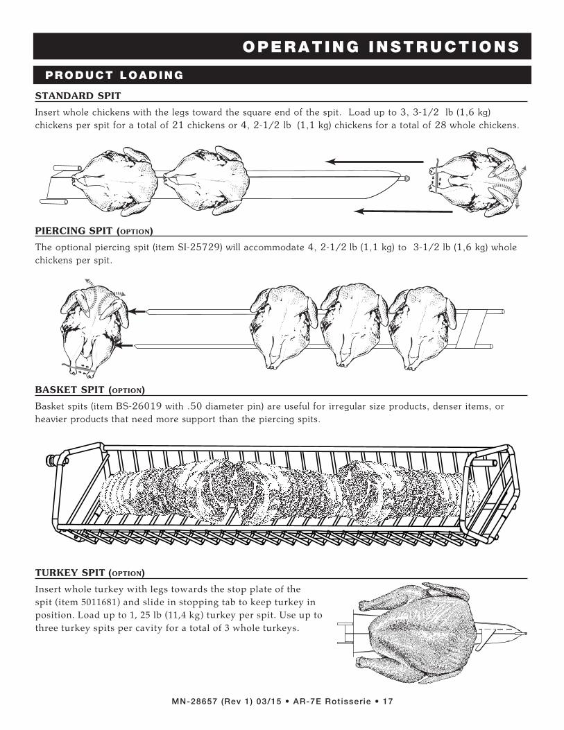
STANDARD SPITS
Each of the seven rotisserie spits includes two welded prongs on the square end and one welded, ridged prong on the tapered end. Insert the two-prong, square end into the two holes indicated on the disk assembly drive wheel in the drawing. Insert the tapered, ridged-prong end into the top hole indicated on the opposite side and maneuver until the ridge catches in the hole. After placing one spit into the oven, rotate the rotisserie using the jog button as shown to load every other position. Continue loading the spits one at a time. This is done to maintain balance within the rotisserie.
OPTIONAL SPITS/BASKETS
When optional spits are used, insert the spits in the drive wheel as indicated in the illustration.
When inserting the basket, put the smooth pin (A) end in first. When removing the basket, the machined pin (B) comes out first.
IMPORTANT NOTE:
When using a partial quantity of standard or optional spits, space the spits evenly as possible around the drive wheel to maintain balance and even rotation.
S P E C I A L A T T E N T I O N : A combination of standard, piercing, and basket spits can be used at the same time but NOT in every spit insertion position. The use of a spit in every position will interfere with the free rotation of the baskets. Using a combination of spits can only be accomplished at significantly reduced rotisserie capacity.
B
A
PRODUCT LOADING
OPERATING INSTRUCTIONS
MN-28657 (Rev 1) 03/15 • AR-7E Rotisserie • 17
STANDARD SPIT
Insert whole chickens with the legs toward the square end of the spit. Load up to 3, 3-1/2 lb (1,6 kg) chickens per spit for a total of 21 chickens or 4, 2-1/2 lb (1,1 kg) chickens for a total of 28 whole chickens.
PIERCING SPIT (OPTION)
The optional piercing spit (item SI-25729) will accommodate 4, 2-1/2 lb (1,1 kg) to 3-1/2 lb (1,6 kg) whole chickens per spit.
BASKET SPIT (OPTION)
Basket spits (item BS-26019 with .50 diameter pin) are useful for irregular size products, denser items, or heavier products that need more support than the piercing spits.
TURKEY SPIT (OPTION)
Insert whole turkey with legs towards the stop plate of the spit (item 5011681) and slide in stopping tab to keep turkey in position. Load up to 1, 25 lb (11,4 kg) turkey per spit. Use up to three turkey spits per cavity for a total of 3 whole turkeys.
PRODUCT LOADING
OPERATING INSTRUCTIONS
MN-28657 (Rev 1) 03/15 • AR-7E Rotisserie • 18
GREASE COLLECTION PROCEDURES
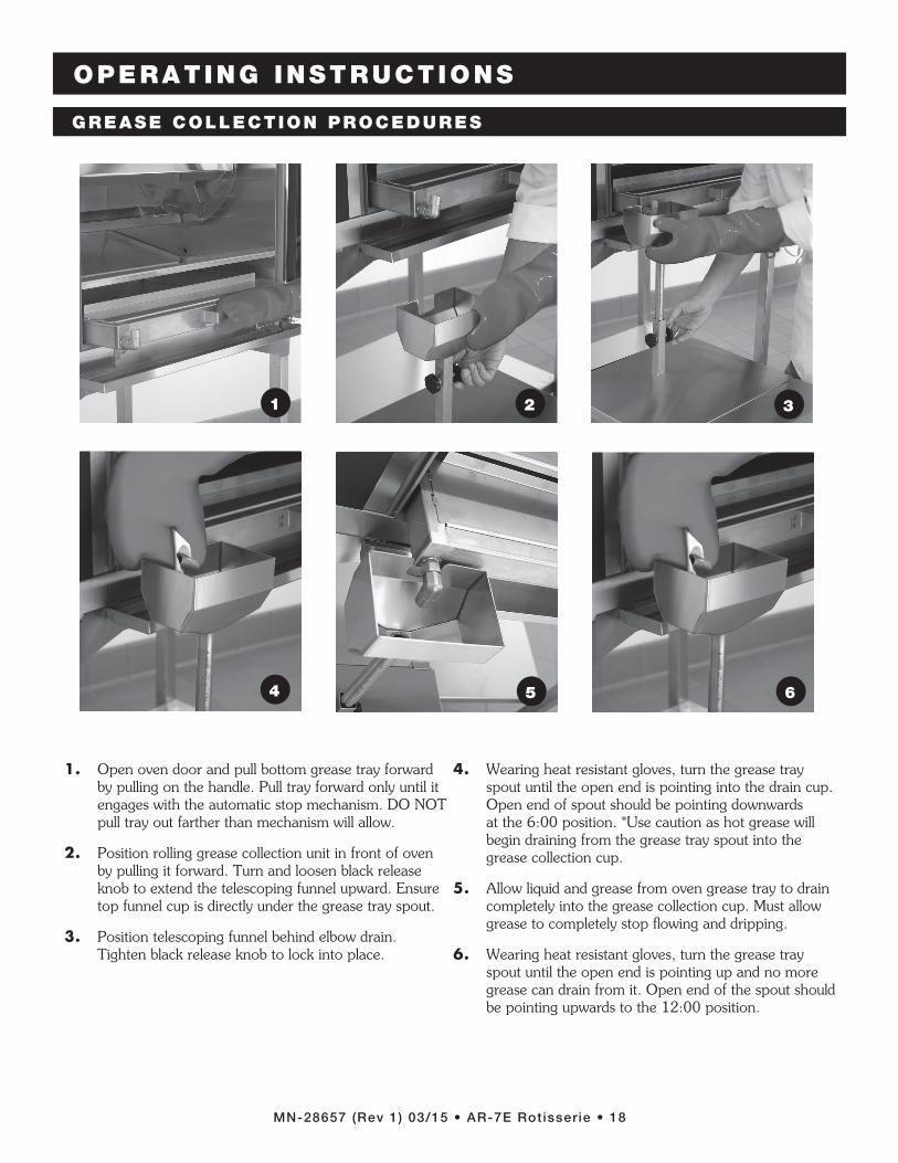
1. Open oven door and pull bottom grease tray forward by pulling on the handle. Pull tray forward only until it engages with the automatic stop mechanism. DO NOT pull tray out farther than mechanism will allow.
2. Position rolling grease collection unit in front of oven by pulling it forward. Turn and loosen black release knob to extend the telescoping funnel upward. Ensure top funnel cup is directly under the grease tray spout.
3. Position telescoping funnel behind elbow drain. Tighten black release knob to lock into place.
4. Wearing heat resistant gloves, turn the grease tray spout until the open end is pointing into the drain cup. Open end of spout should be pointing downwards at the 6:00 position. *Use caution as hot grease will begin draining from the grease tray spout into the grease collection cup.
5. Allow liquid and grease from oven grease tray to drain completely into the grease collection cup. Must allow grease to completely stop fl owing and dripping.
6. Wearing heat resistant gloves, turn the grease tray spout until the open end is pointing up and no more grease can drain from it. Open end of the spout should be pointing upwards to the 12:00 position.
1 2 3
4 5 6

OPERATING INSTRUCTIONS
MN-28657 (Rev 1) 03/15 • AR-7E Rotisserie • 19
7 8 9
10 11
GREASE COLLECTION PROCEDURES
7. Turn and loosen black release knob and gently guide the telescoping funnel downward.
8. Telescoping funnel should be lowered to the level at which it stops without applying force. When properly lowered the funnel will fi t under the oven unit.
9. Push grease tray back into oven and close oven door. Wipe any drippings with a wet cloth from the front of the tray and oven.
10. Check grease level in the rolling grease collection unit after every drain cycle. Using handle at front of rolling grease collection unit, lift lid of unit to observe grease level. If grease level is half full or more, the unit must be emptied into the building grease collection tank or dumpster.
11. Return the rolling grease collection unit to its original position by rolling it completely under the electric rotisserie oven.

CARE AND CLEANING
MN-28657 (Rev 1) 03/15 • AR-7E Rotisserie • 20
PROTECTING STAINLESS STEEL SURFACES
It is important to guard against corrosion in the care of stainless steel
surfaces. Harsh, corrosive, or inappropriate chemicals can completely destroy the protective surface layer
of stainless steel. Abrasive pads, steel wool, or metal implements will abrade surfaces causing damage to this protective coating and will eventually result in areas of corrosion. Even water, particularly hard water that contains high to moderate concentrations of chloride, will cause oxidation and pitting that result in rust and corrosion. In addition, many acidic foods spilled and left to remain on metal surfaces are contributing factors that will corrode surfaces.
Proper cleaning agents, materials, and methods are vital to maintaining the appearance and life of this appliance. Spilled foods should be removed and the area wiped as soon as possible but at the very least, a minimum of once a day. Always thoroughly rinse surfaces after using a cleaning agent and wipe standing water as quickly as possible after rinsing.
CLEANING AGENTS
Use non-abrasive cleaning products designed for use on stainless steel surfaces. Cleaning agents must be chloride-free compounds and must not contain quaternary salts. Never use hydrochloric acid (muriatic acid) on stainless steel surfaces. Always use the proper cleaning agent at the manufacturer's recommended strength. Contact your local cleaning supplier for product recommendations.
CLEANING MATERIALS
The cleaning function can usually be accomplished with the proper cleaning agent and a soft, clean cloth. When more aggressive methods must be employed, use a non-abrasive scouring pad on difficult areas and make certain to scrub with the visible grain of surface metal to avoid surface scratches. Never use wire brushes, metal scouring pads, or scrapers to remove food residue.
CLEANING AND PREVENTATIVE MAINTENANCE
CAUTIONTO PROTECT STAINLESS STEEL SURFACES, COMPLETELY AVOID THE USE OF ABRASIVE CLEANING COMPOUNDS, CHLORIDE BASED CLEANERS, OR CLEANERS CONTAINING QUATERNARY SALTS. NEVER USE HYDROCHLORIC ACID (MURIATIC ACID) ON STAINLESS STEEL. NEVER USE WIRE BRUSHES, METAL SCOURING PADS OR SCRAPERS.
NO
WIRE BRUSH
ES
NO
STEEL PADS
NO SCRAPERS

CARE AND CLEANING
MN-28657 (Rev 1) 03/15 • AR-7E Rotisserie • 21
CAUTIONMETAL PARTS OF THIS EQUIPMENT BECOME EXTREMELY HOT WHEN IN OPERATION. TO AVOID BURNS, ALWAYS USE HAND PROTECTION WHEN OPERATING THIS APPLIANCE.
DANGERDisconnect unit from power source before cleaning or servicing. Failure to observe this precaution can cause electrical shock and personal injury.
CAUTIONAlways follow appropriate state or local health (hygiene) regulations regarding all applicable cleaning and sanitation requirements for equipment.
CLEAN ROTISSERIE DAILY
1. Press the electrical power switch to the "OFF" position.
2. Allow rotisserie surfaces to cool.3. Disconnect the rotisserie from the electrical
power source.4. Remove all detachable items such as spits, grease
deflection trays, and grease collection unit. Drain grease from the drip pan and remove the drip pan from the oven when draining is complete.
5. Remove rotisserie drive assembly from the interior of the oven.a. Supporting the central drive tube assembly,
slide the metal washer and the collar on both sides of the drive tube toward the center of the tube to disengage.
b. Remove the disk drive wheels by pull ing each directly toward the center of the oven compartment.
6. Wash all detached items separately in a ware washing area or sink. Do not use abrasive or corrosive cleaners. Only hot, soapy water is required for the optional Teflon® coated items.
7. Wipe the interior metal surfaces of the oven with a paper towel to remove loose food debris.
8. Clean interior with a damp cloth or sponge and any good commercial detergent at the recommended strength.
9. Spray heavily soiled areas with a water soluble degreaser and let stand for 10 minutes. After 10 minutes, remove soil with a plastic scouring pad.
10. Rinse surfaces thoroughly by wiping with sponge and clean, warm water
11. Remove excess water with sponge and wipe dry with a clean cloth or air dry. Leave door open until interior is completely dry. Always replace all removable parts including drip pan and grease deflection trays before operating.
12. Interior can be wiped with a sanitizing solution after cleaning and rinsing. This solution must be approved for use on stainless steel food contact surfaces.
13. Wipe control panel and door handle(s) thoroughly since these areas harbor food debris and bacteria. Dry the control panel dry with a clean, soft cloth.
14. To help maintain the protective film coating on polished stainless steel, clean the exterior of the cabinet with a cleaner recommended for stainless steel surfaces. Spray the cleaning agent on a clean cloth and wipe with the grain of the stainless steel. For optional color coated exterior surfaces, wipe with a damp cloth or sponge and wipe dry with a clean cloth.
15. Clean glass doors with a standard, commercial glass cleaner.
EQUIPMENT CARE Under normal circumstances, this oven should provide you with long and trouble free service. There is no preventative maintenance required, however, the following Equipment Care Guide will maximize the potential life and trouble free operation of this oven. The cleanliness and appearance of this equipment will contribute considerably to operating efficiency and savory, appetizing food. Good equipment that is kept clean works better and lasts longer.
WASHER
DRIVE TUBE ASSEMBLY
COLLAR
DISK DRIVE
ROTISSERIE CLEANING & MAINTENANCE

CARE AND CLEANING
MN-28657 (Rev 1) 03/15 • AR-7E Rotisserie • 22
It is important to prolong the life of the oven gasket by cleaning this item on a daily basis. The acids and related compounds found in fat, particularly chicken fat, will weaken the composition of the gasket unless cleaned on a daily basis.
Routine cleaning will help protect the composition of the gasket from deterioration caused by acidic foods. After allowing the oven to cool, remove pull-out gasket and wash in hot, soapy water. Do not place gasket in the dishwasher.
DAILY ROTISSERIE GASKET CLEANING
S C RE W S
Remove the screws holding the convection fan panel unto the inside of the cooking chamber. Using a commercial degreaser spray the back and front and allow the degreaser to soften the grease for 10 minutes. Using a plastic scouring pad, scrub any hard deposits and rinse with hot water.
Using a damp sponge and a plastic scouring pad if needed, wipe out any grease deposits that may be built up on the area surrounding the convection element and fan blade, taking care not to bend the element or the blade. A degreaser may be sprayed in this area to help dissolve any grease deposits that may be built up, but only a damp cloth or sponge can be used to remove the dissolved grease.
Reinstall fan panel and tighten screws finger tight.
UNIT MAY BE RUN AFTER CLEANING FOR 30-40 MINUTES TO AID IN DRYING, ALTHOUGH THERE MAY BE SOME SMOKING, WHICH IS NORMAL.
CLEAN ROTTISSERIE CONVECTION BOX
DANGERDisconnect unit from power source before cleaning or servicing. Failure to observe this precaution can cause electrical shock and personal injury.
CAUTIONALWAYS REPLACE THE DOOR GASKET BEFORE CLEANING THE INTERIOR OR OPERATING THE APPLIANCE.
Check for physical damage and loose screws. Correct any problems before they begin to interfere with the operation of the oven.
CHECK OVERALL CONDIT ION OF THE ROTISSERIE ONCE A MONTH
CAUTIONTO PROTECT STAINLESS STEEL SURFACES, COMPLETELY AVOID THE USE OF ABRASIVE CLEANING COMPOUNDS, CHLORIDE BASED CLEANERS, OR CLEANERS CONTAINING QUATERNARY SALTS. NEVER USE HYDROCHLORIC ACID (MURIATIC ACID) ON STAINLESS STEEL. NEVER USE WIRE BRUSHES, METAL SCOURING PADS OR SCRAPERS.
NO
WIRE BRUSH
ES
NO
STEEL PADS
NO SCRAPERS
DANGERAT NO TIME SHOULD THE INTERIOR OR EXTERIOR BE STEAM CLEANED, HOSED DOWN, OR FLOODED WITH WATER OR LIQUID SOLUTION OF ANY KIND. DO NOT USE WATER JET TO CLEAN.
SEVERE DAMAGE OR ELECTRICAL HAZARD
COULD RESULT. WARRANTY BECOMES VOID IF
APPLIANCE IS FLOODED

SERVICE
MN-28657 (Rev 1) 03/15 • AR-7E Rotisserie • 23
Code Description Possible Cause
E-10 Cavity air sensor shorted Cavity air sensor reading < 5°F (-15°C). Verify sensor integrity.See sensor test instructions below.
E-11 Cavity air sensor open Cavity air sensor reading > 517°F (269°C). Verify sensor integrity.See sensor test instructions below.
E-20Product probe is shorted
Oven will cook in time onlyProduct probe reading < 5°F (-15°C). Verify sensor integrity.See sensor test instructions below.
E-21Product probe is open
Oven will cook in time onlyProduct Probe reading > 517°F (269°C). Verify sensor integrity.See sensor test instructions below.
E-30 Under temperature Unit has not reached (set-point - 25°F (4°C)) for more than 90 minutes.
E-31 Over temperatureUnit has been higher than 60°F (16°C) above the maximum cavity set-point for more than 3 minutes. Note: Holding Cabinets with this error code are more than 145°F (63°C) higher than the maximum set-point.
E-32Safety switch open (Aux hi-limit switch) Contact factory.
E-38 Internal software error Contact factory.E-39 Sensor error Contact factory.E-50 Temp. measurement error Contact factory.E-51 Temp. measurement error Contact factory.E-60 Real time clock error Data set to factory default. Ensure that date and time are correct if applicable.E-61 Real time clock error Contact factory.E-64 Clock is not oscillating Contact factory.
E-70Configuration connector error (DIP switch)
Refer to wiring diagram for the particular model and ensure dip switches on the control match the settings called out on the WD. If the dip switch settings are correct according to the print replace the control.
E-78 Voltage low Voltage below 90 VAC on a 125 VAC unit, or below 190 VAC on a 208-240 VAC unit. Correct voltage.
E-79 Voltage high Voltage over 135 VAC on a 125 VAC unit, or over 250 VAC on a 208-240 VAC unit. Correct voltage.
E-80 EEPROM Error Ensure that all temperatures and times are properly set. Contact factory if problem persists.
E-81 EEPROM Error Contact factory.E-82 EEPROM Error Contact factory.E-83 EEPROM Error Contact factory.E-85 EEPROM Error All timers, if previously on, are now off. Possible bad EEPROM.
E-86 EEPROM Error Stored HACCP memory corrupted. HACCP Address reset to 1. Possible bad EEPROM. Contact factory if problem persists.
E-87 EEPROM Error Stored offsets corrupted. Offsets reset to 0. Control may need a recalibration. Possible bad EEPROM. Contact factory if problem persists.
E-88 EEPROM Error All timer set-points are reset to 1 minute. Timers, if previously on, are now off. Possible bad EEPROM.
E-90 Button stuck A button has been held down for > 60 seconds. Adjust control. Error will reset when the problem has been resolved.
E-91 Input failure Contact factory.
E-dS Datakey error Datakey digital signature incompatible. Cycle power, and install compatible Datakey if error persists.
E-dT Datakey error Datakey incompatible with control. Install compatible Datakey.E-dU Datakey unplugged Install Datakey and cycle power to control to clear error.dLto Datalogger has timed out Cycle power. Contact factory if error persists.dLSD Micro SD card not plugged in Plug in SD card and cycle power. Contact factory if error persists.
Note: If in doubt, always cycle the power to the control and contact factory if the problem persists.
To test probe and air sensor:Tes t probe and air sensor by placing sensor in ice water bath and using an ohmmeter set on the ohm scale. The reading should be 100 ohms resistance. If it is more than 2 ohms higher or lower, sensor needs to be replaced.
TROUBLESHOOTING GUIDE

SERVICE
MN-28657 (Rev 1) 03/15 • AR-7E Rotisserie • 24
Part numbers and drawings are subject to change without notice.
DANGERDisconnect unit from power source before cleaning or servicing. Failure to observe this precaution can cause electrical shock and personal injury.
DANGERElectrical connections must be made by a qualified and trained service technician in accordance with applicable electrical codes. Failure to observe this precaution may result in electrical shock, fire, damage to the appliance or personal injury.
DANGERLOCK-OUT OR POST BREAKER PANEL UNTIL SERVICE WORK HAS BEEN COMPLETED.
CAUTIONThis section is provided for the assistance of qualified and trained service technicians only and is not intended for use by untrained or unauthorized service personnel. Failure to observe this precaution may void the warranty.
BULB REPLACEMENT INSTRUCTIONS
To Replace Bulbs:A. Remove four screws holding glass light
cover (CV-26607) and gasket (GS-26609)in place, taking care to not let the glass cover (GL-26608) fall into the oven.
B. Pull bulb out.
C . Push replacement bulb (LP-34213) in place.
D . Re-install glass cover and gasket, securing with four screws removed in step one.
A
B & C
D CAUTIONThe performance of this unit has been optimized using the factory provided bulbs. These bulbs should be replaced with an exact replacement or with a factory recommended replacement. These bulbs have been treated to resist breakage and must be replaced with similarly treated bulbs in order to maintain compliance with NSF standards. DO NOT over-tighten bulbs in their receptacles as this can cause damage to the bulb fi lament.
CAUTIONDO NOT HANDLE NEW BULB WITH BARE HANDS. WHITE COTTON GLOVES SHOULD BE WORN WHEN REPLACING BULBS.
SERVICE
MN-28657 (Rev 1) 03/15 • AR-7E Rotisserie • 25
Part numbers and drawings are subject to change without notice.Part numbers and drawings are subject to change without notice.
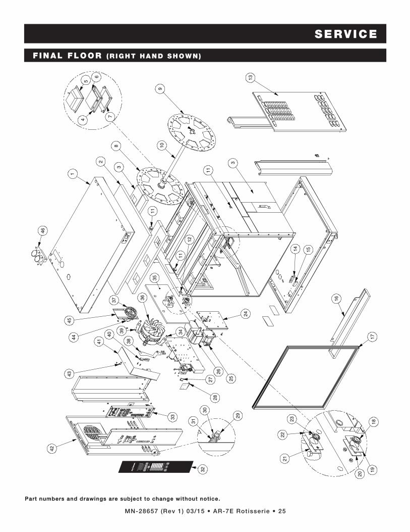
F INAL FLOOR (R IGHT HAND SHOWN)
46
1
108
14 15
17
24
2827
41
4345
44
2
3
3
11
11
37
35
11
12
26
25
16
33
40 3439
38
36
29
31
5
6
4
7
2122
23
20
1918
24
30
9
42
32
13

SERVICE
MN-28657 (Rev 1) 03/15 • AR-7E Rotisserie • 26
Part numbers and drawings are subject to change without notice.
MODEL > CURVED DOOR FLAT DOOR
ITEM DESCRIPTION PART NO. QTY PART NO. QTY
1 SPOT ASSEMBLY, TOP PANEL 5009718 1 5009718 1
2 INSULATION, 1" x 4' x 25' #6, RT2300 (4.5 FT2) IN-24588 1 IN-24588 1
3 INSULATION, NON-CONTROL SIDE IN-28356 1 IN-28356 1
4 GASKET, OVEN LIGHT GS-26609 6 GS-26609 6
5 LAMP ASSEMBLY, 20W LP-34185 6 LP-34185 6
REPLACEMENT BULBS LP-34213 6 LP-34213 6
6 GLASS, OVEN LIGHT GL-26608 6 GL-26608 6
7 COVER FOR OVEN LIGHT CV-26607 6 CV-26607 6
8 DISC ASSEMBLY, CONTROL SIDE WITH PIN 5016037 1 5016037 1
9 DISC ASSEMBLY, NON-CONTROL SIDE 5016038 1 5016038 1
10 DRIVE, TUBE WELD, ASSEMBLY staiNless steel DV-26863 1 DV-26863 1
11 BLOCK, 2 TERMINAL, PORCELAIN BK-33546 4 BK-33546 4
12 7/8" SNAP BUSHING, BLACK BU-3007 4 BU-3007 4
13 PANEL, NON-CONTROL SIDE staiNless steel 1001585 1 1001585 1
burguNdy 1007425 1 1007425 1
14 COVER, MAGNET, INSIDE, SINGLE 1001667 4 1001667 4
15 MAGNET, SMCO, SILVER MA-27568 4 MA-27568 4
16 DRIP TRAY, FRONT 1009063 1 1009063 1
17 GASKET, DOOR GS-25753 1 GS-25753 1
18 BUSHING, SEAL, ROTISSERIE SHAFT BU-27387 1 BU-27387 1
19 SHIM, SEAL, ROTISSERIE MOTOR 1007676 1 1007676 1
20 PLATE, COVER, SEAL, ROTISSERIE MOTOR 1006744 1 1006744 1
21 PLATE, COVER, SEAL, FAN MOTOR 1006783 1 1006783 1
22 SHIM, SEAL, FAN MOTOR 1007675 1 1007675 1
23 BUSHING, SEAL, FAN SHAFT BU-27388 1 BU-27388 1
24 PLATE, MOUNTING, MOTOR 1007015 1 1007015 1
Part numbers and drawings are subject to change without notice.
F INAL FLOOR PARTS L IST
CAUTIONThis section is provided for the assistance of qualified and trained service technicians only and is not intended for use by untrained or unauthorized service personnel. Failure to observe this precaution may void the warranty.
*Not sHowN
coNtiNued oN Next Page

SERVICE
MN-28657 (Rev 1) 03/15 • AR-7E Rotisserie • 27
Part numbers and drawings are subject to change without notice.
MODEL > CURVED DOOR FLAT DOOR
ITEM DESCRIPTION PART NO. QTY PART NO. QTY
25 TRANSFORMER, STEP DOWN TN-33460 1 TN-33460 1
26 MOTOR, AC, DRIVE, RIGHT ANGLE MO-33893 1 MO-33893 1
*MOTOR CAPACITOR MO-33988 1 MO-33988 1
27 SWITCH, PROXIMITY SENSOR SW-33906 1 SW-33906 1
28 BRACKET, DOOR SWITCH 1003474 1 1003474 1
29 STUD, CT M6 x 27mm, 1/4 TURN ST-22193 1 ST-22193 1
30 WASHER, SAFETY, STEEL WS-22195 4 WS-22195 4
31 SPRING, CT M6 x 48, SAFETY SD-22194 1 SD-22194 1
32 PANEL, OVERLAY deluxe PE-25738 1 PE-25738 1
staNdard PE-25869 1 PE-25869 1
INSERT CARD deluxe oNly PE-25740* 1 PE-25740* 1
33 ASSEMBLY, CONTROLS, ELECTRIC CC-34453 1 CC-34453 1
34 SPACER, MOTOR ASSEMBLY SP-26950 4 SP-26950 4
35 INSULATION, CONVECTION BOX IN-27845 1 IN-27845 1
36 CONVECTION MOTOR ASSEMBLY 5002607 1 5002607 1
37 EXHAUST VENT MOTOR FAN WHEEL FA-33481 1 FA-33481 1
38 BRACKET, BLOWER, SAIL SWITCH 1001913 1 1001913 1
39 BRACKET, MOUNTING, AIR DUCT 1002069 3 1002069 3
40 SWITCH, FAN, SAIL SW-33907 1 SW-33907 1
41 AIR DUCT 1002068 1 1002068 1
42 PANEL, CONTROL SIDE staiNless steel 5000949 1 5000949 1
burguNdy 5006216 1 5006216 1
43 CLAMP, HIGH LIMIT CM-2023 1 CM-2023 1
44 FAN, MOTOR, EXHAUST + VENT, 240V, 50/60HZ FA-33221 1 FA-33221 1
45 ASSEMBLY, SPOT, PLATE, HOUSING 5009414 1 5009414 1
46 WELD ASSEMBLY, FAUX DUAL EXHAUST 5009743 1 5009743 1
Part numbers and drawings are subject to change without notice.
DANGERDisconnect unit from power source before cleaning or servicing. Failure to observe this precaution can cause electrical shock and personal injury.
F INAL FLOOR PARTS L IST ( c o n t i n u e d )
*Not sHowN

SERVICE
MN-28657 (Rev 1) 03/15 • AR-7E Rotisserie • 28
Part numbers and drawings are subject to change without notice.Part numbers and drawings are subject to change without notice.
FULL ASSEMBLY (CURVED DOOR, FLAT BACK SHOWN)
6
7
5
17
1
3
4
9
14
15
10
13
1611 2
8
12
18
19
20
21
4
5
DOOR ASSEMBLY(CURVED DOOR, CONTROL S IDE SHOWN)
SERVICE
MN-28657 (Rev 1) 03/15 • AR-7E Rotisserie • 29
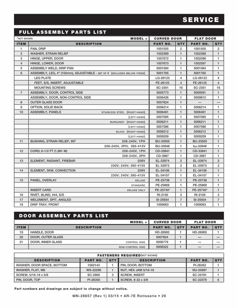
Part numbers and drawings are subject to change without notice.Part numbers and drawings are subject to change without notice.
MODEL > CURVED DOOR FLAT DOOR
ITEM DESCRIPTION PART NO. QTY PART NO. QTY
1 PAN, DRIP 1001555 2 1001555 2
2 WASHER, STRAIN RELIEF 1002389 1 1002389 1
3 HINGE, UPPER, DOOR 1007672 1 1002596 1
4 HINGE, LOWER, DOOR 1007673 1 1002597 1
5 ASSEMBLY WELD, DRIP PAN 5001094 1 5001094 1
6 ASSEMBLY, LEG, 4" (102mm), ADJUSTABLE - set of 4 (includes below items) 5001765 1 5001765 1
LEG PLATE LG-26123 4 LG-26123 4
FEET, S/S, INSERT, ADJUSTABLE FE-26125 4 FE-26125 4
MOUNTING SCREWS SC-2351 16 SC-2351 16
7 ASSEMBLY, DOOR, CONTROL SIDE 5005773 1 5009591 1
ASSEMBLY, DOOR, NON-CONTROL SIDE 5006426 1 5009815 1
8 OUTER GLASS DOOR 5007824 1 — —
9 OPTION, SOLID BACK 5006214 1 5006214 1
10 ASSEMBLY, PANELS stainless steel (right-hand) 5006461 1 5006461 1
(left-hand) 5007085 1 5007085 1
burgundy (right-hand) 5006211 1 5006211 1
(left-hand) 5007086 1 5007086 1
black (right-hand) 5006212 1 5006212 1
(left-hand) 5009209 1 5009209 1
11 BUSHING, STRAIN RELIEF, INT 208-240V, 1PH BU-33505 1 BU-33505 1
208-240V, 3Ph; 380-415V BU-33948 1 bu-33948 1
12 CORD; 6-1/2 FT (1,981 M) 208-240V, 1PH CD-33841 1 CD-33841 1
208-240V, 3Ph CD-3987 1 CD-3987 1
13 ELEMENT, RADIANT, FIREBAR 208V EL-33974 2 EL-33974 2
230V; 240V; 380-415V EL-33973 2 EL-33973 2
14 ELEMENT, 5KW, CONVECTION 208V EL-34106 1 EL-34106 1
230V; 240V; 380-415V EL-34107 1 EL-34107 1
15 PANEL, OVERLAY deluxe PE-25738 1 PE-25738 1
standard PE-25869 1 PE-25869 1
INSERT CARD deluxe only PE-25740* 1 PE-25740* 1
16 RIVET, BLIND, #44, S/S RI-2100 2 RI-2100 2
17 WELDMENT, SPIT, ANGLED SI-25934 7 SI-25934 7
18 DRIP TRAY, FRONT 1009063 1 1009063 1
FULL ASSEMBLY PARTS L IST
MODEL > CURVED DOOR FLAT DOOR
ITEM DESCRIPTION PART NO. QTY PART NO. QTY
19 HANDLE, DOOR HD-26900 1 HD-26900 1
20 DOOR, OUTER GLASS 5007824 1 — —
21 DOOR, INNER GLASS control side 5006779 1 — —
non-control side 5008322 1 — —
FASTENERS REQUIRED
DESCRIPTION PART NO. QTY DESCRIPTION PART NO. QTY
WASHER, DOOR SPACE, BOTTOM 1002143 1 PIN, DOOR, BOTTOM PI-26352 1
WASHER, FLAT, M8 WS-22298 1 NUT, HEX JAM 5/16-18 NU-25897 1
SCREW, 5/16-18 x 5/8 SC-2900 3 SCREW, INSERT SC-25781 1
PIN, DOOR, TOP PI-26350 1 SCREW, 8-32 x 3/8 SC-22378 6
DOOR ASSEMBLY PARTS L IST
(not shown)
*not shown

SERVICE
MN-28657 (Rev 1) 03/15 • AR-7E Rotisserie • 30
Part numbers and drawings are subject to change without notice.Part numbers and drawings are subject to change without notice.
2
1
7
56
34
INTERIOR V IEW
MODEL > CURVED DOOR FLAT DOOR
ITEM DESCRIPTION PART NO. QTY PART NO. QTY
1 BRACKET, ELEMENT 1003595 1 1003595 1
2 WELDMENT, COVER, BLOWER 5005782 1 5005782 1
3 BLOWER COVER SCREW CL-24089 2 CL-24089 2
4 BLOWER COVER SCREW LOCK WASHER WS-24090 2 WS-24090 2
5 STUDWELD (SPOT) DUCT, BLOWER 5005848 1 5005848 1
6 GASKET, AIR BOX GS-27389 1 GS-27389 1
7 PLATE, SUPPORT 1006650 1 1006650 1

SERVICE
MN-28657 (Rev 1) 03/15 • AR-7E Rotisserie • 31
Part numbers and drawings are subject to change without notice.Part numbers and drawings are subject to change without notice.
9
10
11
8
7
12
13
4
3
2
5
6
1
ELECTRICAL SERVICE V IEW
MODEL > CURVED DOOR FLAT DOOR
ITEM DESCRIPTION PART NO. QTY PART NO. QTY
1 AIR DUCT 1002068 1 1002068 1
2 MOTOR DRIVE, 230V, AC MO-33893 1 MO-33893 1
3 TRANSFORMER, STEP DOWN TN-33460 1 TN-33460 1
4 RELAY, POWER RL-33930 5 RL-33930 5
5 SWITCH, HIGH LIMIT SW-34454 1 SW-34454 1
6 BOARD, POWER SUPPLY, 12V DC, SWITCH BA-36144 1 BA-36144 1
7 TERMINAL BLOCK BK-3023 1 BK-3023 1
8 FAN, BLOWER MOTOR CAPACITOR, 4 UF FA-33931 1 FA-33931 1
9 CONTACTOR, 208/240V 3 POLE 25 AMP CN-3052 2 CN-3052 2
RESISTOR, MOV, SURGE PROTECTOR RS-3578* 2 RS-3578* 2
10 FUSE, 15A, CLASS G FU-34772 2 FU-34772 2
11 FUSE HOLDER FU-34771 1 FU-34771 1
12 MOTOR, CONVECTION FAN, 220-240V M0-33892 1 M0-33892 1
13 EXHAUST VENT MOTOR FAN WHEEL, 240V, 50/60HZ FA-33221 1 FA-33221 1
14 SWITCH, FAN, SAIL SW-33907* 1 SW-33907* 1
15 DRIVE MOTOR CAPACITOR MO-33988* 1 MO-33988* 1
*Not sHowN
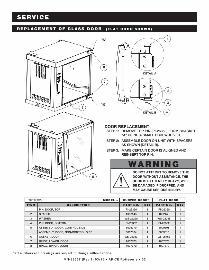
SERVICE
MN-28657 (Rev 1) 03/15 • AR-7E Rotisserie • 32
Part numbers and drawings are subject to change without notice.
SERVICE
Part numbers and drawings are subject to change without notice.
“A”
A
B“B”
1
2
3
4
8
7
6
5
REPLACEMENT OF GLASS DOOR (FLAT DOOR SHOWN)
DOOR REPLACEMENT: STEP 1: REMOVE TOP PIN (PI-26350) FROM BRACKET
"A" USING A SMALL SCREWDRIVER.
STEP 2: ASSEMBLE DOOR ON UNIT WITH SPACERS AS SHOWN (DETAIL B).
STEP 3: MAKE CERTAIN DOOR IS ALIGNED AND REINSERT TOP PIN.
MODEL > CURVED DOOR* FLAT DOOR
ITEM DESCRIPTION PART NO. QTY PART NO. QTY
1 PIN, DOOR, TOP PI-26350 1 PI-26350 1
2 SPACER 1002143 1 1002143 1
3 WASHER WS-22298 1 WS-22298 1
4 PIN, DOOR, BOTTOM PI-26352 1 PI-26352 1
5 ASSEMBLY, DOOR, CONTROL SIDE 5006779 1 5009591 1
ASSEMBLY, DOOR, NON-CONTROL SIDE 5007824 1 5009815 1
6 GASKET, DOOR GS-25753 1 GS-25753 1
7 HINGE, LOWER, DOOR 1007673 1 1007673 1
8 HINGE, UPPER, DOOR 1007672 1 1007672 1
DETAIL A
DETAIL B
*Not sHowN
WARNINGDO NOT ATTEMPT TO REMOVE THE DOOR WITHOUT ASSISTANCE. THE DOOR IS EXTREMELY HEAVY, WILL BE DAMAGED IF DROPPED, AND MAY CAUSE SERIOUS INJURY.

SERVICE
MN-28657 (Rev 1) 03/15 • AR-7E Rotisserie • 33
Part numbers and drawings are subject to change without notice.Part numbers and drawings are subject to change without notice.
5
6
7
8
“A”
“A”
“A”“B”
1
2
3
4
STAINLESS STEEL BACK PANEL (5006214 )
Installation instructions:
STEP 1: REMOVE GASKET AND ALL SCREWS ON INSTALLATION SIDE.
STEP 2: INSTALL 1006652 USING (16) SC-25849 SCREWS IN LOCATIONS MARKED “A.”
STEP 3: INSTALL 1006746 INTO 1006652 USING (4) SC-27843 SCREWS, (8) SC-2459 SCREWS AND (4) 1002822 SPACERS.
STEP 4: SEAL COMPLETE PERIMETER OF OPENING WITH SILICONE “B”.
MODEL > CURVED DOOR FLAT DOOR
ITEM DESCRIPTION PART NO. QTY PART NO. QTY
1 GASKET TAPE GS-28123 1 GS-28123 1
2 PANEL, INTERIOR S/S BACK 1006652 1 1006652 1
3 SCREW, PAN HEAD SC-25849 16 SC-25849 16
4 INSULATION, FIBERGLASS IN-2003 1 IN-2003 1
5 SCREW, NC, PHILL TRUSS SC-2459 8 SC-2459 8
6 SCREW, PAN HEAD, PHILLIPS SC-27843 12 SC-27843 12
7 PANEL, EXTERIOR S/S BACK 1006746 1 1006746 1
8 SPACER, SOLID BACK 1002822 4 1002822 4

SERVICE
MN-28657 (Rev 1) 03/15 • AR-7E Rotisserie • 34
Part numbers and drawings are subject to change without notice.
6
7
9
2
413
10
8
5
GREASE COLLECTION UNIT (5012271 )
ITEM DESCRIPTION PART NO. QTY
1 WASHER, LOCK, 1/2" DIA WS-24893 4
2 NUT, 1/2-13 S/S JAMB NU-24736 4
3 CASTER, STEM 3" SWIVEL, WITH BRAKE CS-24857 2
4 CASTER, STEM 3" SWIVEL CS-24858 2
5 COVER, SPACER 5012270 1
6 FUNNEL, TUBE 5012268 1
7 FUNNEL, COVER 5012266 1
8 GREASE PAN 5012265 1
9 FRAME WELDMENT 5012264 1
10 DIRECTIONAL PANEL SPACER 1006601 4
11 DRIP PAN COVER 1011621 2
12 ASSEMBLY WELD, DRIP PAN WITH DRAIN 5012290 1
12
11
11

AR-7E Rotisserie Operat ion & Care Manual • 35

AR-7E Rotisserie Operat ion & Care Manual • 36

AR-7E Rotisserie Operat ion & Care Manual • 37

TRANSPORTATION DAMAGE and CLAIMSAll Alto-Shaam equipment is sold F.O.B. shipping point, and when accepted by the carrier, such shipments become the property of the consignee.Should damage occur in shipment, it is a matter between the carrier and the consignee. In such cases, the carrier is assumed to be responsible for the safe delivery of the merchandise, unless negligence can be established on the part of the shipper.
1. Make an immediate inspection while the equipment is still in the truck or immediately after it is moved to the receiving area. Do not wait until after the material is moved to a storage area.
2. Do not sign a delivery receipt or a freight bill until you have made a proper count and inspection of all merchandise received.3. Note all damage to packages directly on the carrier’s delivery receipt.4. Make certain the driver signs this receipt. If he refuses to sign, make a notation of this refusal on the receipt.5. If the driver refuses to allow inspection, write the following on the delivery receipt:
Driver refuses to allow inspection of containers for visible damage.6. Telephone the carrier’s office immediately upon finding damage, and request an inspection. Mail a written confirmation of the
time, date, and the person called.7. Save any packages and packing material for further inspection by the carrier.8. Promptly file a written claim with the carrier and attach copies of all supporting paperwork.
We will continue our policy of assisting our customers in collecting claims which have been properly filed and actively pursued. We cannot, however, file any damage claims for you, assume the responsibility of any claims, or accept deductions in payment for such claims.
LIMITED WARRANTYAlto-Shaam, Inc. warrants to the original purchaser only that any original part that is found to be defective in material or workmanship will, at Alto-Shaam's option, subject to provisions hereinafter stated, be replaced with a new or rebuilt part.The original parts warranty period is as follows: For the refrigeration compressor on Alto-Shaam Quickchillers™, five (5) years from the date of installation of appliance. For the heating element on Halo Heat® cooking and holding ovens, as long as the original purchaser owns the oven. This
excludes holding only equipment. For all other original parts, one (1) year from the date of installation of appliance or fifteen (15) months from the shipping date, whichever
occurs first. The labor warranty period is one (1) year from the date of installation or fifteen (15) months from the shipping date, whichever occurs first. Alto-Shaam will bear normal labor charges performed during standard business hours, excluding overtime, holiday rates or any
additional fees. To be valid, a warranty claim must be asserted during the applicable warranty period. This warranty is not transferable.THIS WARRANTY DOES NOT APPLY TO:
1. Calibration.2. Replacement of light bulbs, door gaskets, and/or the replacement of glass due to damage of any kind.3. Equipment damage caused by accident, shipping, improper installation or alteration.4. Equipment used under conditions of abuse, misuse, carelessness or abnormal conditions, including but not limited to, equipment
subjected to harsh or inappropriate chemicals, including but not limited to, compounds containing chloride or quaternary salts, poor water quality, or equipment with missing or altered serial numbers.
5. Damage incurred as a direct result of poor water quality, inadequate maintenance of steam generators and/or surfaces affected by water quality. Water quality and required maintenance of steam generating equipment is the responsibility of the owner/operator.
6. Damage caused by use of any cleaning agent other than Alto-Shaam's Combitherm® Cleaner, including but not limited to damage due to chlorine or other harmful chemicals. Use of Alto-Shaam's Combitherm® Cleaner on Combitherm® ovens is highly recommended.
7. Any losses or damage resulting from malfunction, including loss of product, food product, revenue, or consequential or incidental damages of any kind.
8. Equipment modified in any manner from original model, substitution of parts other than factory authorized parts, removal of any parts including legs, or addition of any parts.
This warranty is exclusive and is in lieu of all other warranties, express or implied, including the implied warranties of merchantability and fitness for a particular purpose. In no event shall Alto-Shaam be liable for loss of use, loss of revenue or profit, or loss of product, or for any indirect, special, incidental, or consequential damages. No person except an officer of Alto-Shaam, Inc. is authorized to modify this warranty or to incur on behalf of Alto-Shaam any other obligation or liability in connection with Alto-Shaam equipment.
RECORD THE MODEL AND SERIAL NUMBER OF THE APPLIANCE FOR EASY REFERENCE. ALWAYS REFER TO BOTH MODEL AND SERIAL NUMBER IN ANY CONTACT WITH ALTO-SHAAM REGARDING THIS APPLIANCE.
Model: ______________________________________________ Date Installed: ______________________________________________________Voltage: ______________________________________________ Purchased From: ___________________________________________Serial Number: _____________________________________________________________________________________________________________
W164 N9221 Wate r S t ree t � P .O . Box 450 � Menomonee Fa l l s , W i scons in 53052-0450 � U .S .A . PHONE: 262.251.3800 • 800.558-8744 USA/CANADA FAX: 262.251.7067 • 800.329.8744 U.S.A. ONLY
www.alto-shaam.comP R I N T E D I N U . S .A .
Effective November 1, 2012