Embed Size (px)
Citation preview

Pergamon
PII: S0360-1285(95)00016-1
Prog. Energy Combust. Sci. Vol. 24, pp. 565-600, 1998 © 1998 Elsevier Science Ltd
Printed in Great Britain. All rights reserved 0360-1285/98 $19.00
A REVIEW OF SPRAY IGNITION PHENOMENA: PRESENT STATUS AND FUTURE RESEARCH
S. K. Aggarwal Department of Mechanical Engineering, University of Illinois at Chicago, 842 W. Taylor Street, Chicago,
IL 60607, U.S.A.
Abstract--Theoretical and experimental studies dealing with the spray ignition phenomena are reviewed. Two major topics covered are external-source ignition of liquid fuel sprays and spontaneous spray ignition. Experimental and theoretical investigations of external-source ignition of sprays employing different configurations are discussed first. Three major topics included here are: (i) ignition of quiescent and flowing fuel sprays; (ii) ignition of monodisperse and polydisperse sprays; and (iii) ignition of single-component and multicomponent fuel sprays. Then, experimental studies of autoignition of sprays employing constant-volume enclosures, injection in a uniform air flow, and shock tube techniques, are discussed. Theoretical investigations dealing with spray autoignition phenomena range from phenomenological models to one-dimensional numerical models using global one-step as well as detailed multistep chemistry, and to multidimensional simulations with reduced mechanisms. These models are also discussed in the review. Finally, some advanced topics which are common to both external-source ignition and spontaneous ignition are identified and discussed. An attempt is made to provide a common link between the three dominant ignition modes in sprays, namely individual droplet ignition, droplet cluster ignition, and spray ignition. In a similar manner, common features of external-source ignition and spontaneous ignition of sprays are identified. A general spray ignition model along with important numerical and physical issues are presented. The effect of pressure on spray ignition processes is also discussed. Potential topics for further research are suggested. © 1998 Elsevier Science Ltd. All rights reserved.
Keywords: spray ignition, autoignition, droplet ignition.
CONTENTS
Nomenclature 565 1. Introduction 566 2. Spray Ignition Using an External Source 567
2.1. Ignition of Quiescent Two-phase Mixtures 568 2.2. Ignition of Flowing Two-phase Mixtures 571 2.3. Existence of Optimum Droplet Size and Equivalence Ratio 574 2.4. Ignition of Multicomponent Fuel Sprays 577
3. Autoignition of Liquid Fuel Sprays 581 3.1. Autoignition in a Constant Volume Enclosure 583 3.2. Autoignition of Sprays Injected in a Heated Air Flow 583 3.3. Autoignition of Sprays in a Shock Tube 585 3.4. Theoretical and Computational Studies on Autoignition of Sprays 587
4. Important Issues and Remaining Challenges 590 4.1. External-source Ignition versus Spontaneous Ignition 590 4.2. Computational Modeling of Spray Ignition Phenomena 591 4.3. Dominant Spray Ignition Modes 594 4,4. Effect of Pressure on Spray Ignition Phenomenon 595
5. Summary and Concluding Remarks 597 Acknowledgements 599 References 599
CA, C., K
Cos
Cd
Da, dk
Di-m
do
E
NOMENCLATURE
g constants in Eq. (14)
P droplet drag coefficient in Eq. (15)
Pr drag coefficient in Eq. (8)
F
droplet diameter R
diffusivity of species i in the gas mixture Rek
initial droplet diameter for a monodisperse spray Sc
ignition energy, also the activation energy t
565
gravitational acceleration
pressure
gas-phase Prandtl number
radial coordinate
gas constant (Eq. (1))
droplet Reynolds number
gas-phase Schmidt number
temporal variable
566 S.K. Aggarwal
rig ignition delay time
Ts droplet surface temperature
T~ wall temperature
u, v, w velocity components
Ud droplet velocity
ug gas velocity
Vr magnitude of droplet relative velocity
x , y , z droplet position coordinates
Y~ fuel vapor mass fraction at the droplet surface
z axial coordinate
global or overall equivalence ratio, also a gen- eralized gas-phase variable in Eq. (3)
gas thermal conductivity
/x gas viscosity
p density
Subscripts
k droplet group
1 liquid-phase property
g gas-phase property
s droplet surface property
1. INTRODUCTION
Spray ignition represents phenomenon of great fundamental and practical interest. Spray combustion is employed in numerous practical systems including industrial furnaces, boilers, gas turbines, diesels, spark- ignition engines, and rocket engines. Ignition is a crucial event in the operation of these systems. The ignition of fuel sprays injected in jet engine combustors is an important phenomenon due to the desirability of fast ignition and its relation to the issue of flame stabilization. Similar considerations apply to spark ignition engines, where fast, well-controlled ignition is important to engine efficiency and emissions. In diesel engines, the self-ignition of fuel sprays injected into a high temperature and pressure environment represents a critical event in their operation. On the other hand, there are situations or systems where the occurrence of ignition must be avoided. Prevention of autoignition in the mixture delivery system of prevaporizing-premixing gas turbine combustors, and prevention of knock in spark ignition engines are two such examples. Other examples include fire safety in earth and space environments, and explosions in mines and industrial settings. Studies of spray ignition are also important from a scientific viewpoint, since ignition represents a classical phenom- enon that is rich in fundamental processes of chemical
kinetics (both low and high temperature kinetics), fluid mechanics, phase change, and two-phase transport. Since ignition is inherently a transient process, fundamental studies dealing with spray ignition are directly relevant to other transient combustion phenomena such as flame stabilization, flammability limits and extinction, as well as to combustion efficiency and emissions.
Ignition can be defined as the initiation of rapid exothermic reactions or the appearance of a flame in a combustible mixture that may be caused with the help of an external stimulus such as an electric spark, or without any external source such as autoignition in a compres- sion ignition engine. Consequently, studies dealing with ignition can be broadly classified into two types: those dealing with ignition due to an external source and others investigating processes of self ignition. The external source that provides localized heating in a combustible mixture may be an electric spark or another kind of heat source, such as a pocket of hot fluid, heated surface, plasma jet, or laser. Self or spontaneous ignition generally occurs due to a global heating of the mixture; for example, ignition of a spray following its injection into the high-temperature environment of a diesel engine, ignition behind a shock wave, or ignition of a gaseous mixture leading to knock in a spark ignition engine.
A successful ignition event generally begins with an "ignition kernel", a localized region of high reactivity and heat release, followed by the establishment of a flame. This depends upon a number of parameters, such as the structure of the local flow field, the mixture composition, and the mode of depositing ignition energy. For liquid fuel-air mixtures, additional parameters are the spatial distribution of droplets in the vicinity of the "ignition kernel", the droplet size distributions, and the fraction of fuel in the vapor and liquid phases. Regarding the concept of ignition kernel for spray ignition, two fundamental issues are worth mentioning. First is the concept of ignition kernel applicable to both external- source and spontaneous ignition situations. Based on a review of various ignition studies, it can be stated that the concept is perhaps valid in essentially all external-source ignition situations, and many autoignition situations. The formation and growth of an ignition kernel which may provide a common link between the external-source ignition and autoignition situations. While the existence of an ignition kernel is evident in spark ignition and other external ignition configurations, it may also be a viable concept in many autoignition situations. In a diesel engine, for example, the ignition is initiated in a localized region which can be conceptualized as an ignition kernel. Evidence of this behavior is provided by two experimental studies dealing with spray ignition in a constant volume system. In the first study, Sato et al.
observed ignition to occur in the stagnation region of the fuel spray tip, while in the second study, Edwards et al. 2
observed that the ignition event was initiated inside a vortex which was generated due to Kelvin-Helmhoitz instability of the shear layer, s These aspects of ignition phenomenon focusing on the ignition location in
Spray ignition phenomena 567
two-phase mixture thermal boundary layer
I O O
/ / '~ ignition of a cloud spray isnition o ~ o / droplet 18nitiou /
°C>- / / / / / / ~ / / / / / /
heated surface
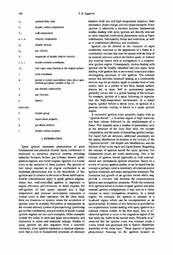
Fig. 1. A schematic of a flowing two-phase mixture ignited in the thermal boundary layer of a heated surface. Three ignition modes, namely, the droplet ignition, droplet cluster ignition, and
spray ignition, are illustrated.
autoignition situations and the role of large scale vortex structures in the ignition process have not been considered in most previous studies. The formation and growth of the spark kernel is of course different for various ignition situations, determined by the ignition source characteristics (spark energy and gap for spark ignition, wall temperature for ignition by a hot wall, and gas temperature for autoignition), two-phase properties (equivalence ratio, velocity, turbulence level, pressure, temperature), and spray characteristics (fuel type, droplet size, size distribution). On the other hand, in an externally-ignited situation, the processes following the attainment of minimum spontaneous ignition tempera- ture for the mixture inside the ignition kernel are similar to those in an autoignition situation.
The second issue which is more specific to spray ignition deals with the occurrence of ignition in the vicinity of an individual droplet, cluster of droplets, or globally in a spray. In order to elucidate the differences among these ignition modes, we consider the ignition of a liquid fuel spray flowing over a heated wall, as shown schematically in Fig. 1. The three ignition modes are depicted in this figure, and which one is likely to occur depends upon the flow conditions, spray properties, liquid fuel loading, and wall temperature etc. The state of ignition for an individual droplet (ignition mode 1) represents the appearance of a flame surrounding the droplet or in the wake region, with a dimension on the order of the droplet diameter. An ignition event for a droplet distinguishes the state of pure vaporization from that of a diffusion flame around the droplet. This has significant implications figr spray flames with regard to flame stability and the amount of pollutants formed. The importance of droplet ignition phenomenon in relation to the formation of soot and NOx was noted in the experimental study of Rah et al. 4 In spray combustion modeling, the identification of this event is important since it determines the amount of heterogeneous burning involved, and the rates of mass and heat transport are significantly altered following its occurrence. For a liquid fuel spray, on the other hand, ignition represents the appearance of a global sheath flame that is associated with the entire spray (ignition mode 3) and not with any individual droplet, and has a dimension few orders of magnitude larger than the droplet diameter. The ignition of a droplet cloud or cluster (mode 2) represents an
intermediate situation, and can be utilized to bridge the results of studies dealing with modes 1 and 3. The literature review indicates that all three modes of ignition have been investigated. In particular, there is a vast body of literature, both experimental and theoretical, dealing with modes 1 and 3. Since the evaporation and combustion of an isolated droplet in a quiescent environment has been a classical problem for analytical and experimental studies, and ignition represents a transition from the state of evaporation to that of combustion, the droplet ignition phenomena has been studied more extensively compared with the other two ignition phenomena. The ignition processes in a droplet cloud have been investigated by Annamalai and coworkers, 5"6 Sichel and coworkers, 7 and Bellan and Harstad. 8 A review of these studies is provided by Annamalai and Ryan. 5 The combustion characteristics of a droplet cloud have been extensively studied by Chiu and coworkers. 9'1°
The present review primarily deals with ignition mode 3, as it covers various experimental and theoretical/ computational works focusing on the spray ignition phenomenon. Topics dealing with spray ignition using an external stimulus as well as spontaneous ignition are covered. Although the focus is essentially on spray ignition phenomena, some of the studies dealing with homogeneous mixtures, because of their pertinence to spray ignition, are also mentioned. Obviously, ignition phenomena have a much broader scope and range of applications than what is covered in this review. For example, there is a very extensive body of literature dealing with the fundamental ignition theory, as well as ignition in gaseous and multiphase mixtures. For the latter, the multiphase mixtures may involve two or more phases, and the dispersed phase may be solid or liquid. However, the focus of this review will be limited to ignition of two-phase mixtures consisting of oxidizer in the continuous phase and liquid fuel in the dispersed phase. In particular, the review covers the following two major topics:
1. Spray ignition using an external source. 2. Spontaneous ignition in sprays. Previous studies of these two topics are reviewed in
Sections 2 and 3, respectively. Some related but advanced topics on which further research is needed are discussed in Section 4. Conclusions are presented in Section 5.
2. SPRAY IGNITION USING AN EXTERNAL SOURCE
Ignition of a liquid fuel spray by an external source has been extensively investigated in both quiescent and flowing spray configurations. The quiescent or nearly- quiescent spray configuration has been preferred in several experimental and numerical studies, since complications arising due to convective effects and turbulence are avoided, thus facilitating the comparison of measurements and predictions. Moreover, such studies provide baseline data for ignition delay time, ignition energy, and ignitability limits, as well as allow
568 S.K. Aggarwal
detailed investigation of some relevant processes of spray ignition. Previous investigations of spray ignition have employed a variety of ignition sources including electric sparks, heated surfaces, pockets of hot fluid, combustion torches, plasma jets, and lasers. The first two ignition sources have been most commonly used in spray ignition studies. A distinguishing feature of spark ignition is the transient deposition of ignition energy in a short duration (tens to hundreds of microseconds), and in a concentrated region (characteristic size: millimeter and smaller) of a combustible mixture. The basic idea then is to examine whether or not this energy deposition leads to a state of ignition and appearance of a flame, identify this state of ignition, and determine how long it takes to attain this state, i.e. the ignition delay time. Consequently, most experimental and theoretical studies have focused on determining the dependence of ignition energy and ignition time on important parameters which include droplet size, equivalence ratio, and velocity. In addition, several numerical investigations have analyzed the transient processes (following the deposition of ignition energy) leading to the state of ignition. Most previous studies have considered a monodisperse, single- component fuel spray, although some have examined the effects of drop size distribution by using polydisperse sprays, and liquid fuel composition by considering bicomponent fuel sprays.
2.1. Ignition of Quiescent Two-phase Mixtures
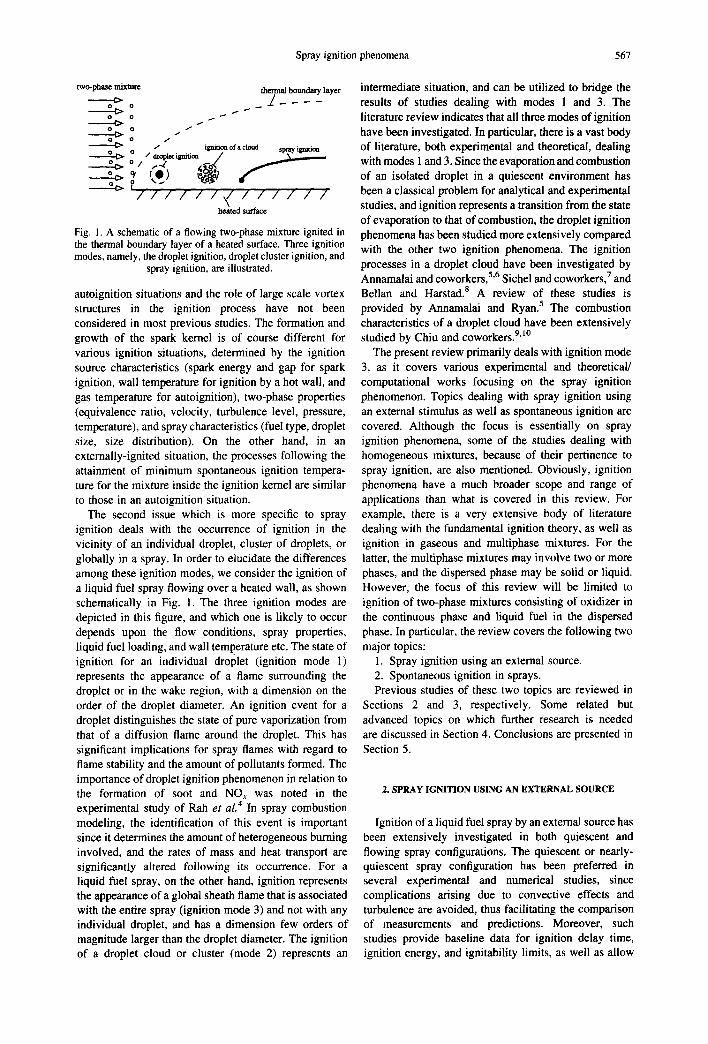
A quiescent combustible two-phase mixture has been used in several experimental and theoretical investiga- tions. Lefebvre and coworkers H-14 reported a series of experimental-analytical studies dealing with spark ignition of homogeneous (gaseous) and heterogeneous (spray) mixtures. For the heterogeneous case, a mist of fuel droplets was generated by atomizing liquid fuel (using a spinning cup atomizer) in an air flow, and the uniform two-phase mixture was ignited by using a capacitance type spark. Both quiescent 12 and flowing mixtures13.J4 were considered. Results were presented in terms of the minimum ignition energy as a function of the Sauter mean diameter (30 < 150 #m), equivalence ratio (0.4 < ~b < 1.0), fuel volatility, pressure, and initial vapor concentration. For each case, the minimum spark energy was obtained by optimizing the spark gap and duration through a series of experiments. A typical plot of ignition energy versus the spark gap taken from Ballal and Lefebvre 12 is shown in Fig. 2. The procedure to obtain a minimum ignition energy by optimizing the spark gap is quite apparent in this figure. Several experiments were then conducted to obtain the depen- dence of minimum ignition energy on SMD, equivalence ratio, and pressure. Typical results from Ballal and Lefebvre 12 for nearly quiescent mixtures (U < 20 era/s) are depicted in Figs 3 and 4. These results clearly demonstrate the strong influence of SMD and ~ on minimum ignition energy. As indicated in Fig. 3, Ernin increases monotonically as the Sauter mean diameter of the spray is increased, and as the fuel volatility is
1000 -- = ~h.f.c~
° 100
10 0 0.4 0.8 1.2
electrode gap width/era
Fig. 2. Variation of ignition energy with electrode gap width for different fuels, iso-octane (i.o.), diesel oil (d.o.), and heavy fuel oil (h.f.o.) (P = 0.2 atm, SMD = 100#m, and ~b = 0.65).
Adapted from Ballal and Lefebvre. 12
500
100
~ 1 0 . . II
I I
1 E dx~/
0.1 I0 100 500
S.m.d.~m
Fig. 3. Minimum ignition energy versus Sauter mean diameter (SMD) for different fuels, iso-octane (i.o.), diesel oil (d.o.), and heavy fuel oil (h.f.o.) (P = 1 atm, ¢k = 0,65). Solid lines rep- resent the calculated values based on a phenomenological
model. Adapted from Ballal and Lefebvre. '2
reduced. According to the discussion of Ballal and Lefebvre, ~2 the effect of volatility appears through the effect of transfer number which implies that the ignition process is vaporization-dominated rather than kineticaUy-dominated. In addition, Emin has a monotonic decrease as ~ is increased and pressure is increased. Note
Spray ignition phenomena 569
I00
_ ~ • - e
1o - O ~ e ~
1 ~ ~ 0 ~m
• ~ " , ,~0 20
0.11 i ~ - i . . i j. , . I _ ~ 0.4 0.6 0.8 1.0
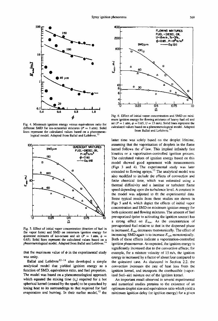
Fig. 4. Minimum ignition energy versus equivalence ratio for different SMD for iso-octane/alr mixtures (P = 1 atm). Solid lines represent the calculated values based on a phenomeno-
logical model. Adapted from Ballal and Lefebvre.]2
I00 ~JIESCENT MIXTURES SMO/J.m FUEL, DIESEL OIL
P,IO'N/m" ,/,.o.e5
o ~ Eq. (18)
".. A IOO " ~
O 0.?.5 O.5 O75 IO c~
Fig. 5. Effect of initial vapor concentration (fraction of fuel in the vapor form) and SMD on minimum ignition energy for quiescent mixtures of iso-octane and air (P = 1 atm, $ = 0.65). Solid lines represent the calculated values based on a phenomenological model. Adapted from Ball al and Lefebvre.14
that the maximum value of ~ in the experimental study was unity.
Ballal and Lefebvre 12-14 also developed a simple analytical model that yielded ignition energy as a function of SMD, equivalence ratio, and fuel properties. The model was based on a phenomenological approach which equated the mixing time (tq) required for a hot spherical kernel (created by the spark) to be quenched by losing heat to its surroundings to that required for fuel evaporation and burning. In their earlier model, 12 the
4OC[_ FLOWlNGr~ MIXTURES' | HR~EL DIESEL OIL
2r1¢~-- U 15m/I ,Tu,3%, "-I ~.o6s. ~.,O'N..Z i / ~ SMO~m . . . . . Eq.{21)
F o \ o
0 0.25 05 0.75 1.0 o,
Fig. 6. Effect of initial vapor concentration and SMD on mini- mum ignition energy for flowing mixtures of heavy fuel oil and air (P = 1 atm, ~b = 0.65, U = 15 m/s). Solid lines represent the calculated values based on a phenomenological model. Adapted
from BaUal and Lefebvre. 14
latter time was solely based on the droplet lifetime, assuming that the vaporization of droplets in the flame kernel follows the d2-1aw. This implied infinitely fast kinetics or a vaporization-controlled ignition process. The calculated values of ignition energy based on this model showed good agreement with measurements (Figs 3 and 4). The experimental study was later extended to flowing sprays. 13 The analytical model was also modified to include the effects of convection and finite chemical time, which was estimated using a thermal diffusivity and a laminar or turbulent flame speed depending upon the turbulence level. A constant in the model was adjusted to fit the experimental data. Some typical results from these studies are shown in Figs 5 and 6, which depict the effects of initial vapor concentration and SMD on minimum ignition energy for both quiescent and flowing mixtures. The amount of fuel prevaporized (prior to activating the ignition source) has a strong effect on Emin. As the concentration of prevaporized fuel relative to that in the dispersed phase is increased, Emia decreases monotonically. The effect of increasing SMD again is to increase Emi n monotonically. Both of these effects indicate a vaporization-controlled ignition phenomenon. As expected, the ignition energy is significantly increased due to the convective effects; for example, for a mixture velocity of 15 m/s, the ignition energy is increased by a factor of about four compared to the quiescent case. As discussed in Section 2.2, the convection increases the rate of heat loss from the ignition kernel, and transports the combustible (vapor- ized fuel-air) mixture out of the ignition kernel.
An important result observed in several experimental and numerical studies pertains to the existence of an optimum droplet size and equivalence ratio which yield a minimum ignition delay (or ignition energy) for a given

570 S.K. Aggarwal
fuel. This aspect, discussed later in the present review, was not observed in the experimental studies of Ballal and Lefebvre. 12-14 The optimum equivalence ratio was probably not obtained because the investigation was limited to lean mixtures (¢ < 1.0). As noted later in the present review, the optimum ql depends on fuel volatility, but is generally greater than unity. Regarding the optimum droplet size, their investigation 12 consid- ered a polydisperse spray represented by the SMD, with a minimum SMD of 30 #. Since ignition behavior has been observed to be governed by smaller droplets, it is possible that an optimum droplet size existed for their conditions, but the study did not particularly focus on finding its value. It should also be noted that although their phenomenological model 14 shows good agreement with measurements, it does not provide details about the transient processes involved during ignition.
The first numerical investigation of spray ignition phenomena based on a detailed analysis of the transient two-phase processes was reported by Aggarwal and Sirignano) 5 A transient, one-dimensional model employing an Eulerian-Lagrangian approach was devel- oped to simulate ignition of a dilute, monodisperse fuel- air spray in contact with a planar hot wall. Important features of the model are:
1. Initially (at t = 0), a quiescent, uniform, fuel-air mist is contained in a one-dimensional cylindrical tube, with one end of the tube assumed to be a hot isothermal surface, acting as the ignition source. Although, the mixture is stagnant initially, the gas-phase motion resulting from heating from the ignition source and chemical reactions, as well as droplet motion, are included in the one-dimen- sional model. Consequently, the droplet relative motion (with respect to gas) is considered, and so are the processes of mass, momentum, and energy transfer between the phases.
2. The chemistry is modeled by using a global one- step reaction scheme with nonunity exponents of fuel and oxygen concentrations, as proposed by Westbrook and Dryer./6 Two fuels considered are n-hexane and n-decane.
3. A single-component fuel is considered. Internal droplet heating is included by using the infinite- conductivity and finite-conductivity models. These models are described in Aggarwal e t al. 27
4. The two-phase processes are resolved on a scale smaller than the distance between droplets. This is necessary for accuracy since the thermal layer thickness at the time of ignition is comparable to this scale.
5. The possibility of an individual droplet ignition is precluded.
6. The state of ignition is defined by a zero heat flux condition at the ignition source. This is equivalent to a thermal runaway condition.
The numerical model ~5 was employed to examine the transient two-phase processes during the ignition period. In addition, a parametric study was conducted to examine the effects of droplet size, equivalence ratio
&
~ANE rk- ~..5 pm
200 I 1 I I 2 4 5 8 lO
E r
~0 0ECANE, rk. ~.lpm
7OO \
6OO
I I I I 3000 2 4 6 8
Er
Fig. 7. Effect of overall equivalence ratio on ignition delay time for a monodisperse spray calculated by using three different reduced mechanisms. Ignition delay time is normalized by the numerical temporal time step (5 txs). Droplet radius is 52.5/~m for n-hexane (a) and 37.1 ~m for n-decane (b). Curves 1 and 2 are for the one-step scheme with unity and nonunity exponents, respectively, while curve is for the three-step scheme. Adapted
from Aggarwal. 29
and fuel volatility. The results indicated the existence of an optimum equivalence ratio (for a given droplet size) and an optimum droplet size (for a given equivalence ratio) corresponding to a minimum ignition delay time. This can be explained by recognizing that for a gaseous (homogeneous) mixture, there exists an optimum equivalence ratio that yields a minimum ignition delay time. Then, for the heterogeneous case, one can define two equivalence ratios, namely the overall equivalence ratio (t~m) and the local gas-phase equivalence ratio (~i) in the ignition zone (flame kernel), the latter being determined by other parameters such as droplet size (d0, ~,,, fuel volatility and ignition source temperature. For example, ~i can be expected to increase as dk is reduced for a given q~,, or as qt,~ is increased for a given dk, or as fuel volatility is increased. Consequently, the plot of ti 8 versus dk exhibits an optimum droplet size (dopt) corresponding to the optimum q~i, where tig is minimized. For a fixed Cm, any droplet size larger than dopt yields a locally fuel lean mixture (local mixture ratio smaller than

Spray ignition phenomena 571
the optimum ~bi) in the ignition zone, while droplet sizes smaller than dopt yields a locally fuel rich mixture. For the same reason, dopt can be expected to depend upon fuel volatility, i.e. it would be smaller for a more volatile fuel. Using a similar argument, the existence of an optimum q~,, can be explained. Some typical results taken from Aggarwa129 are given in Fig. 7. These figures will be discussed in a later section where the effects of using three different reaction mechanisms are studied. However, the existence of an optimum equivalence ratio is clearly indicated for both n-hexane and n-decane fuels.
Another important aspect revealed by the study of Aggarwal and Sirignano 15 pertains to the stochastic nature of the spray ignition process. It was shown that ignition of a heterogeneous mixture is not a deterministic process, but a statistical one. This means that for a given set of conditions or parameters, only a range of ignition delays or ignition energies, and not a particular fixed value, can be found. In other words, a given ignition delay only represents certain probability of ignition. Subsequently, the probabilistic nature of spray ignition phenomena has been observed experimentally by Sommer ~8 and Cernansky and coworkers, ~9-21 and numerically by Wehe and Ashgriz. 22 For example, in the experimental study of Sommer, 18 the wall tempera- ture for ignition was observed to depend on location of the nearest droplet stream from the wall, which is a stochastic quantity in real situations. Similarly, in the numerical study of Aggarwal and Sirignano, t5 the ignition delay time was observed to depend on the droplet location nearest to the heated wall. This means that a specified number of deterministic calculations can be performed to deduce the ignition probability, or the probability of having a ignition delay between (say) t~g and tig + dtig. Additional discussion of the statistical nature of the spray ignition phenomena is provided by Sirignano. 23
In a subsequent study, Aggarwal and Sirignano 24 extended their numerical model to polydisperse sprays in order to investigate the effect of droplet size distributions on spray ignition behavior. The polydisperse model was then used to examine the ignition behavior of a bidisperse spray. Similar to monodisperse sprays, results again indicated the existence of an optimum droplet size for a given equivalence ratio and vice versa. Regarding the size distribution, it was demonstrated that the Sauter mean diameter is not capable of representing the ignition characteristics of a polydisperse spray. Instead, poly- disperse spray ignition behavior is well represented by an equivalent monodisperse spray based on a area mean diameter. Since the area mean diameter is more biased toward the small droplets, the implication is that the ignition of a polydisperse spray is dominated by the smaller droplets, evidence of which has been provided by numerical 25"26 as well as experimental 27 studies. This observation is, however, at variance with the experi- mental study of Dietrich et al.21 which concluded that the ignition behavior of bidisperse sprays is better correlated by the Sauter mean diameter rather than the area mean diameter. They attributed this apparent contradiction to
the different ignition sources and ignition criteria. Aggarwal and Sirignano 24 used a heated wall as the ignition source, and ignition was defined by a zero heat flux condition at this wall. Dietrich et al., 2~ on the other hand, used an electric spark, and ignition was defined by the visible propagation of a flame. Based on the results of various experimental and numerical studies, we attribute this apparent contradiction to different ignition criterion, and not due to different ignition sources, since flame propagation in a spray was found 28 to be better correlated by Sauter mean diameter rather than area mean diameter.
The ignition studies discussed so far employed a global one-step mechanism in the two-phase model. Aggarwa129 evaluated the use of global one-step mechanism with nonunity exponents by comparing its predictions with those using a three-step mechanism due to Glassman and Dryer. 3° Some typical results from that study are shown in Fig. 7. These results indicate that while a global scheme with unity exponents of fuel and oxygen concentrations yields unacceptable results, that with nonunity exponents yields predictions that compare well with those of a three-step scheme. Both the one-step scheme with nonunity exponents and the three-step scheme also predicted the existence of optimum droplet sizes and equivalence ratios (Fig. 7). In addition, the predictions of these two schemes for the dependence of ignition delay on wall temperature showed good agreement with each other and with the experimental results of Miyasaka and Mizutani. 31
2.2. Ignition o f Flowing Two-phase Mixtures
Compared with the quiescent mixture case, there are only a few studies dealing with the ignition of flowing sprays. An important issue here relates to the effects of forced and buoyant convection on ignition delays and ignitability limits. For laminar forced convection, this effect should be characterized in terms of the Reynolds number, while for the turbulent case, the effects of turbulence on transient two-phase processes during the ignition kernel growth as well as on global ignition behavior should be investigated. For the buoyant convection, the effect should be characterized in terms of a relevant Froude number. In addition, transient processes in the ignition region should be studied under normal-gravity and reduced-gravity conditions, and the effects of gravity on ignitability limits should be quantified. Some past investigations have considered the effects of forced convection on spray ignition phenomenon, however, effects of buoyant convection and turbulence have not been investigated in previous studies.
Ballal and Lefebvre ~4 conducted an experimental study dealing with spark ignition of flowing (U ---- 15 m/ s) two-phase mixtures. Similar to their study of quiescent mixtures, ignition data were reported in terms of minimum ignition energy as a function of SMD, equivalence ratio, fuel type, and mixture velocity. A typical result from this study is portrayed in Figs 5 and 6, where the minimum ignition energy, as defined earlier, is

572 S.K. Aggarwal
35 1
30
25
20
15
10
5 ' 0
=' Experiment: Tw=1150K, d=117.0 microns • Experiment: Tw=1150K, d=104.0 o Experiment: Tw=1150K, d= 53.0
---e--Pred. [15]: Tw=1500K, d= 52.5 , , i ~ , " - i " "; " 7 " , - " , " '~ " 7 " , - - , - "~ - ~ " , " - , - ' " T " I" - , " - " ; " - i t
I I I •
• / I t
, .~" o
- i t . _ . . . i t . - ' • " 0
,0, 0
' 0 0 0
, t , i , , , , I , , , , I , , , , I , , , ,
0.1 0.2 0.3 0.4 0.5 Y (ram)
Fig. 8. Ignition location X as a function of the distance from the heated surface for four droplet diameters; surface temperature = 1150 K. Adapted from Sommer. ~s
3O
25
2O
15
10
5
0 20
¢
= Experiment: y--0.01mm, Tw=1150K • Experiment: y=0.15mm, Tw=1150K o Experiment: y=0.02mm, Tw=1150K • Pred. [15]: y=0.15mm, Tw=1500K
• <>
m .
I i i i I i L i [ i i i t i r
4 0 6 0 8 0 1 0 0 1 2 0 d0un)
Fig. 9. Ignition location X as a function of droplet diameter for three values of the distances from the heated surface; surface temperature = 1150 K. Adapted from Sonuner. Is
plotted as a function of the initial fuel vapor concen- tration, i.e. the fraction of fuel in the vapor form. Although Figs 5 and 6 are for two different fuels, their comparison indicates that the minimum ignition energy increases noticeably due to the forced convection effects. A phenomenological explanation given was that the rate of heat loss from the ignition kernel increases signifi- cantly due to the convective effect, requiring greater spark energy to compensate for that loss.
Two other notable experimental studies dealing with flowing sprays are due to Graves et al. 32 and Sommer is. Graves et aL 32 investigated the ignition of Jet-A fuel (kerosene) sprays in the convective thermal boundary layer of a heated vertical tube, while Sommer investi- gated the ignition of a stream of n-decane droplets flowing in the buoyant thermal boundary layer of a vertical heated plate. In the first study, the free stream velocity range was 1.0-5.0 m/s, and the SMD range (polydispersed spray) was 20-200ttm. The wall temperature (Tw) required for ignition was measured as a function of free stream velocity, equivalence ratio, and SMD. As expected, Tw was observed to increase as the free stream velocity was increased. The plot of Tw
versus equivalence ratio exhibited a minimum Tw corresponding to an optimum equivalence ratio, provid- ing experimental verification of the existence of an optimum equivalence ratio, as reported in the numerical studies of Aggarwal and Sirignano ]5'24 and Aggarwal. 29 It should be noted that Tw in the experimental study of Graves et al. 32 can be thought of as a measure of ignition energy. However, Tw was found to be insensitive to changes in droplet size. This may be attributed to the fact that all parameters could not be controlled indepen- dently, and the ignition criterion used was somewhat arbitrary as the ignition was defined by the appearance of any flame. There was also noticeable prevaporization which mitigated the effects of droplet size on ignition. Another significant result observed in the experimental study was that the ignition of individual droplets was found to be prominent at the lean limit.
In the experimental investigation reported by Sommer, ts the droplet diameter range was 30-150 #m. The measured ignition data were presented in terms of the ignition length, measured from the plate leading edge to the ignition location, as a function of droplet size and distance between the droplet stream and the plate. The

Spray ignition phenomena 573
115
110
_• 105
¢: -~ loo
I,M
95
90
-- DECANE /
I I I I 0 40 80 120 160
d o , ~m
Fig. 10. Minimum ignition energy versus initial droplet dia- meter for flowing n-decane and air mixtures. V0 = 0.5 m/s, (1) ~ = 1, (2) ¢~ = 2. Adapted from Aggarwal and Nguyen. 3'* ,oo -
98
E 96
tLI
92
go I I I 0 1 2 3
EQUIVALENCE RATIO. d>
Fig. 11. Minimum ignition energy versus equivalence ratio for flowing n-decane and air mixtures. V0 = 0.5 ntis, (1) do = 40 ~,
(2) do = 80 #. Adapted from Aggarwal and Nguyen. ~
experimental results showed reasonable agreement with the numerical predictions of Aggarwal and Sirignano. 15 Some representative results from this study as well as comparison with predictions are depicted in Figs 8 and 9. It should be noted that the numerical study analyzed a transient spray ignition problem, while the experimental study considered a steady problem. Consequently, in order to compare the two results, the predicted ignition delay time was converted into an ignition length by calculating the distance traversed by a moving droplet. Figure 8 shows the measured and computed ignition delay lengths plotted versus the distance between the droplet stream and heated plate for different droplet diameters. The variation of measured and predicted ignition delay lengths with droplet size is depicted in Fig. 9. While the qualitative agreement is quite good, measurements consistently indicated a shorter ignition delay length than predictions. The discrepancy is principally due to the effects of convective heat transfer present in the experimental investigation, but not
120 --
100 .
E
oo
ao I I I I 25 50 75 100
V0, crrl/s
Fig. 12. Minimum ignition energy versus mixture velocity. ~ = l, do = 100/z, (1) n-hexane, (2) n-decane. Adapted from Aggar-
wal and Nguyen. 34
considered in the numerical model. In the latter, the ignition process is initiated due to the conduction heat transfer between the hot wall and the air. However, the corresponding heat transfer in the experiments occurs in a buoyant thermal boundary layer of the heated plate. Another potential cause for the discrepancy is the effect of convection on the interphase heat and mass transfer rates. Since droplet relative velocity is important in the experimental study which considers a moving droplet stream, but negligible in the numerical study, the convective effect enhances the vaporization rate and thus leads to faster ignition in the experimental study. There may also be some effect of radiative heat transfer between the hot surface and droplets, which is neglected in the numerical model.
It is interesting to note that in spite of some differences in flow conditions and fuels used, the basic phenomenon examined in the two experimental studies 18'32 was quite similar, i.e. spray ignition in the thermal boundary layer of a heated surface. As the gas temperature increases along the flow direction in the thermal boundary layer, droplets are heated and vaporization is initiated, followed by fuel vapor-air mixing and chemical reactions. Depending upon the two-phase parameters, the ignition may occur globally in the boundary layer which is defined as spray ignition, or it may occur in the vicinity of an individual droplet, which is termed as droplet ignition.
Cernansky and coworkers t9-2t and Polymeropoulos and coworkers 27"33 also examined the ignition behavior of flowing two-phase mixtures. However, the flow velocity was relatively small, and these investigations did not particularly focus on the convective effects. Aggarwal and Nguyen 34 extended the quiescent spray ignition model t5'29 to a flowing two-phase mixture in an open tube. The mixture was ignited by a localized heat source located at the center of the tube. The character- istic time and length scales of this source were assumed to be typical of an electric spark. Ignition energy was deposited at a constant volumetric rate, and events leading to ignition (or no ignition) were followed by solving the
574 S.K. Aggarwal
30,
• ~ 2~
>- 20' a: tu 15" z
I(>
5'
Yo2=17.2%
I i i i I i i I I I I i i i
I0
E 8 >.
UJ z ,,t 4,
2"
yo2-- 21%
0 ' lb ' 1~5 ' 2b ' 2B ' 3'0 ' 3'5 ' ' t O DROPLET DIAMETER pm
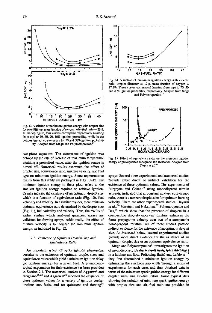
Fig. 13. Variation of minimum ignition energy with droplet size for two different mass fraction of oxygen. Air-fuel ratio = 23.8. In the top figure, four curves correspond respectively (starting from top) to 70, 50, 20, 10% ignition probability, while in the bottom figure, two curves are for 70 and 50% ignition probabil-
ity. Adapted from Singh and Polymeropoulos. 27
two-phase equations. The occurrence of ignition was defined by the rate of increase of maximum temperature attaining a prescribed value, after the ignition source is turned off. Numerical results examined the effect of droplet size, equivalence ratio, mixture velocity, and fuel type on minimum ignition energy. Some representative results from this study are portrayed in Figs 10-12. The minimum ignition energy in these plots refers to the smallest ignition energy required to achieve ignition. Results indicate the existence of an optimum droplet size which is a function of equivalence ratio (Fig. 10), fuel volatility and velocity. In a similar manner, there exists an optimum equivalence ratio determined by the droplet size (Fig. 11), fuel volatility and velocity. Thus, the results of earlier studies which analyzed quiescent sprays are validated for flowing sprays. Additionally, the effect of mixture velocity is to increase the minimum ignition energy, as indicated in Fig. 12.
2.3. Existence of Optimum Droplet Size and Equivalence Ratio
An important aspect of spray ignition phenomena pertains to the existence of optimum droplet sizes and equivalence ratios which yield a minimum ignition delay (or ignition energy) for a given fuel. A phenomeno- logical explanation for their existence has been provided in Section 2.1. The numerical studies of Aggarwal and Sirignano 15'24 and Aggarwal 2s reported the existence of these optimum values for a variety of ignition config- urations and fuels, and for quiescent and flowing 34
2 0
10
o
GAS-FUEL RATIO
Fig. 14. Variation of minimum ignition energy with air-fuel ratio, droplet diameter = 12 tt, mass fraction of oxygen = 17.2%. Three curves correspond (starting from top) to 70, 50, and 20% ignition probability, respectively. Adapted from Singh
and Polymeropoulos. 27
100 >-
10' ! j "
PREVAIIQRIZED
N-HEPT
EQUIVALENCE RATIO
/ • 1 " E - | . i - i
I i 0 .O 0 . 5 ~O 1 . 5 2 . 0 2 . 5 " 3 ~ 0 " 3 1 5
Fig. 15. Effect of equivalence ratio on the minimum ignition energy of prevaporized n-heptane and methanol. Adapted from
Danis et al. 2°
sprays. Several other experimental and numerical studies provide either direct or indirect validation for the existence of these optimum values. The experiments of Burgoyne and Cohen, a5 using monodisperse tetralin aerosols, indicated that at constant mixture equivalence ratio, there is a nonzero droplet size for optimum burning velocity. There are other experimental studies, Hayashi et al., 36 Mizutani and Nakajima, 37 Polymeropoulos and Das, 3s which show that the presence of droplets in a combustible droplet-vapor-air mixture enhances the flame propagation velocity over that of a comparable homogeneous mixture. All of these studies provide indirect evidence for the existence of an optimum droplet size. As discussed below, several experimental studies provide more direct evidence for the existence of an optimum droplet size or an optimum equivalence ratio.
Singh and Polymeropoulos 27 investigated the ignition of monodisperse, tetraiin aerosols using spark discharges in a laminar gas flow. Following Bailai and Lefebvre, ~2 they first determined a minimum ignition energy by optimizing the electrode gap width through a series of experiments for each case, and then obtained data in terms of the minimum spark ignition energy for different droplet sizes and air-fuel ratios. Some typical data showing the variation of minimum spark ignition energy with droplet size and air-fuel ratio are provided in

Spray ignition phenomena 575
100 . . . . . l N-HEPTANE
• ( PRE-VAP
.1 1 .... , ,
! 0 . 0 0 . 5 1.0 1.5 2.0 EQUIVALENCE RATIO
Fig. 16. Effect of equivalence ratio and droplet diameter on the minimum ignition energy of n-heptane sprays (for three differ- ent diameters) and prevaporized mixtures. Adapted from Danis
et al. 2°
I°° 1 \ .,..m,'r.,m,~
1° 1 ~, e.o.+,o.7,u
% %. +k
+ ."o,o ",o ,+o"'?:":o 5 0 OROPLET DIAMETER (jam)
Fig. 17. Effect of droplet diameter on the minimum ignition energy of n-heptane sprays. Adapted from Danis et al. 2°
100 METHANOL i i i
i i . I PR~-V
.1 / II o.0 015 +io 2.0
EQUIVALENCE RATIO
Fig. 18. Effect of equivalence ratio and droplet diameter on the minimum ignition energy of methanol sprays and prevaporized
mixtures. Adapted from Danis et al. ~
Figs 13 and 14. These plots provide clear experimental evidence for the existence of an optimum droplet size and equivalence ratio that yield a minimum in the ignition energy. In addition, they indicate that the optimum droplet size depends on the overall mixture ratio. For example, the optimum droplet diameter decreases as the oxygen mass fraction is increased. As discussed earlier, an increase in O2 concentration implies a leaner mixture, which would require that the optimum droplet size be reduced (for a fixed overall mixture ratio) so as to provide more fuel vapor in the ignition zone.
Danis e t al . 2° also used spark ignition to investigate
the effects of droplet size and equivalence ratio on the ignition of monodisperse n-heptane and methanol sprays flowing in a tube. The flow velocities ranged from 0.25 to 1.5 m/s, droplet Reynolds numbers between 0.1 and 1.2, and flow Reynolds numbers between 100 and 300. Following earlier experimental studies, z2'27 the mini- mum ignition energy E~n was obtained by optimizing the spark gap. In order to present results in a consistent manner, the definition of E~i, was further modified such that it represents spark energy to produce an ignition probability of 50%. The criterion for successful ignition was that a visible flame propagate at least 5 cm into the mixture. Then, the minimum ignition energy Emi, was measured over a droplet diameter range of 30-57 #m, an equivalence ratio range of between 0.44-1.8, as well as for prevaporized fuels. The experimental study provided several useful results, some of which are depicted in Figs 15-18. First of all, it established the existence of an optimum equivalence ratio (between 1.5 and 2.0) for the prevaporized n-heptane fuel. This is indicated in Fig. 15. The authors pointed out that the corresponding optimum equivalence ratio for prevaporized methanol could not be determined since fuel rich methanol mixtures could not be tested due to condensation problems. Second, the lean ignition limit for both the prevaporized fuels was found to be approximately 0.55. Third, the effects of droplet size and equivalence ratio on E~ , were quantified, as shown in Figs 16-18. Results for n-heptane, Fig. 16, indicate that for a given droplet size, E~n decreases with increasing q~. While an optimum ~ was not obtained explicitly, all E~a~ curves appear to be approaching an optimum ~b. Moreover, according to these curves, this optimum ~b seems to be increasing with increasing droplet size, as observed in previous numerical studies. 15"29'34 Figure 16 also demonstrates the existence of optimum droplet size for a given q~. Although, no explicit optimum droplet sizes are reported, it is evident from the figure that for certain equivalence ratio, there is an optimum droplet size for a minimum En~,. This is shown more clearly in Fig. 17, where the n-heptane ignition energy is plotted as a function of droplet diameter, with prevaporized data appearing at a diameter of 0 t~m. The dashed lines represent interpolations between the lowest diameter tested and the prevaporized case. These lines clearly indicate that an optimum droplet diameter between 10 and 30 for the spray ignition case. As indicated in Fig. 18, similar observations regarding the optimum droplet size and equivalence ratio can be made for the methanol spray. The ignition energy plots in Figs 16 and 18 also indicate that the lean ignition limit is extended for both n-heptane and methanol sprays compared to the prevaporized cases. It is also interesting to note that the ignition energy for methanol sprays is about 3-5 times higher than that for the corresponding n-heptane sprays, due to the higher latent heat of vaporization of methanol fuel. This is in agreement with the numerical predictions of Gutheil. 26
The experimental studies reported by Sommer ~s and Graves e t al . 32 provide further evidence for the existence of optimum values corresponding to a minimum ignition
576 S.K. Aggarwal
Z • 8qo.o
~ II!0.0 •
~ 0
..~'-.A FUEl.
a TI : q7 ¢
~=so 8.8. stl~Al~ 0 1, t , I , ,, I I
.0130 1.000 ~ . ~ 0 3.000 q .000 $ .0O0 II .O00
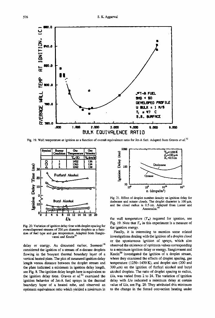
BULK EQUIVRLENCE RRTIO Fig. 19. Wall temperature at ignition as a function of overall equivalence ratio for Jet-A fuel. Adapted from Graves et al. 32
t=
o
Teml~mmm: i V eke-it7 T .00 V.~'m/~
O I l~Z 136 ~' 1363 134
, . , $ 1242 138
~ - _ . ~
0
( ~ ' Butyl Alcohol
1,~s- ~ 1
v(~" 2 4 6 g 10 12 14 16 18 ~0 tla
Fig. 20. Variation of ignition delay time with droplet spacing for monodispersed streams of 200 #,m diameter droplets as a func- tion of fuel type and gas temperature. Adapt~l from Sangio-
vanni and Kestin 39
delay or energy. As discussed earlier, Sommer ]8 considered the ignition of a stream of n-decane droplets flowing in the buoyant thermal boundary layer of a vertical heated plate. The plot of measured ignition delay length versus distance between the droplet stream and the plate indicated a minimum in ignition delay length, see Fig. 8. The ignition delay length here is equivalent to the ignition delay time. Graves e t al. 32 examined the ignition behavior of Jet-A fuel sprays in the thermal boundary layer of a heated tube, and observed an optimum equivalence ratio which yielded a minimum in
1000 .
d~ 10o
:! 10 "
to'
T.-I200K dp-100~m Rc'0.5 em
. . . . . . . i . . . . . . . . i . . . . . . . .
10 9 10 t° tO Is n (dropslm 3)
Fig. 21. Effect of droplet number density on ignition delay for dodecane and octane clouds. The droplet diameter is 100 t~m, and the cloud radius is 0.5 cm. Adapted from Laster and
Annamalai.40
the wall temperature (Tw) required for ignition, see Fig. 19. Note that Tw in this experiment is a measure of the ignition energy.
Finally, it is interesting to mention some related investigations dealing with the ignition of a droplet cloud or the spontaneous ignition of sprays, which also observed the existence of optimum values corresponding to a minimum ignition delay or energy. Sangiovanni and Kestin 39 investigated the ignition of a droplet stream, where they examined the effects of droplet spacing, gas temperature (1250-1450 K), and droplet size (200 and 300 #m) on the ignition of furfuyl alcohol and butyl alcohol droplets, The ratio of droplet spacing to radius, L/a, was varied from 2 to 24. The variation of ignition delay with L/a indicated a minimum delay at certain value of L/a, see Fig. 20. They attributed this minimum to the change in the forced convection heating under

Spray ignition phenomena 577
700
tig
50C
30C
(11 HEXANE I 0 NE /
121 /
/ i I
_ _ . ,,. ° °
I I I o z o , d.6 o a ilo
YLO
Fig. 22. Ignition delay time, normalized by the computational time step, plotted as a function of the initial mass fraction of (1) liquid hexane, and (2) liquid decane. The computational time step is 5 t-s, initial droplet diameter is 10Or,m, hot wall tem- perature is 15OOK, and overall equivalence ratio is unity.
Adapted from Aggarwal as
interactive conditions. It should be noted that the variation of Ua amounts to changing the local equivalence ratio, and a minimum in ignition delay at certain Ida implies an optimum equivalence ratio. Laster and Annamalai 4° reported a numerical study of the ignition of a droplet cloud in a quiescent atmosphere, The results were presented in terms of ignition delay time as a function of fuel loading and other parameters for dodecane and octane fuels. A minimum in ignition delay time was observed at a certain value of fuel loading (or cloud denseness) for low-volatility (dodecane) clouds, see Fig. 21. Since, a variation in fuel loading implies a variation in equivalence ratio, the existence of an optimum equivalence ratio is indicated by their results. Livengood and Wu 41 reported an experimental
study on the autoignition behavior of hydrocarbon fuels in a rapid compression machine. It was observed that a minimum value of ignition delay occurred at approxi- mately stoichiometric mixture conditions, implying the existence of an optimum equivalence ratio for an autoignition situation. Additional evidence for the existence of an optimum droplet size and equivalence ratio is provided by a numerical study 25 on the autoignition of dilute methanol sprays in a constant volume combustor. A detailed kinetic mechanism was employed for the oxidation of methanol fuel. Details of this study are discussed in Section 3.4. A relevant result here pertains to the existence of optimum values for the autoignition case. A similar result for the existence of an optimum equivalence ratio (see Fig. 38) was reported by Mawid and Aggarwal 4z who employed a transient axisymmetric model based on the KIVA code to study the autoignition behavior of liquid fuel sprays near a hot surface in a constant volume combustor. These results are also discussed in Section 3.4.
2.4. Ignition of Multicomponent Fuel Sprays
Most petroleum-derived liquid fuels used in gas- turbine, spark-ignition, and diesel engines, are mixtures of many compounds with wide variations in properties. The ignition behavior of a multicomponent fuel spray is expected to be distinctly different from that of a single- component spray for several reasons. First, the behavior of an isolated fuel droplet is altered drastically if it contains more than one fuel. 43 This is due to the slow mass diffusion process inside the droplet which, in combination with the volatility differential, results in a highly thin diffusion layer near the droplet surface.
1000 ~-
1- Yt.o • 0 / 2 - v,., - o.oi / / 3 - YI.o'O.I / /
800 4 - YCO '~ 0.2 ~ 2
/ / ti0 600 3
40,
I I I I 20 0 40 80 120 140
do.
Fig. 23. Normalized ignition delay time versus the initial droplet diameter for different values of Yt.o. See caption of Fig. 22 for the values of other parameters. Adapted from Aggarwal. 4s

578 S.K. Aggarwal
HEXANE DECANE 20 Ill 0 1001
,o
2.0 / / 1 3 1
1.0 i I i I i I 0.6 Q7 0.8 0.9
1000/Tw, I/K
Fig. 24. Normalized ignition delay time versus the reciprocal of hot wall temperature for different initial composition of a bicomponant fuel. See caption of Fig. 22 for the values of other parameters. Adapted from Aggarwal 4~
Second, the spray processes for the multicomponent case 1000 differ significantly from the single-component case due to different vaporization rates of constituent fuels. 44 This can result in nonuniform fuel distribution in the combustor, and thereby alter the kinetic-related 800 processes such as ignition, flame stability, and pollutant levels. Third, the multicomponent fuel chemistry can be significantly different than that of a pure fuel-air mixture. These differences in the processes of vaporization and chemical kinetics could lead to a distinctly different 600 ignition behavior for a multicomponent fuel spray tlg compared to that for a single-component fuel spray.
It is interesting to note that, while the vaporization/ combustion behavior of an isolated multicomponent fuel 100 droplet has been extensively investigated, 4a the studies dealing with the ignition and combustion characteristics of multicomponent fuel sprays are relatively few. Aggarwa145 reported a numerical study on the ignition of a bicomponent fuel spray. The transient, one- 2000 dimensional model 15 used earlier to study the ignition of a single-component fuel spray in the vicinity of a hot wall was extended to multicomponent fuel sprays. Both monodisperse and polydisperse size distributions were considered. A global one-step reaction scheme with nonunity exponents of fuel and oxygen concentrations was employed for a multifuel system. The transient thermal and compositional fields inside the droplet were resolved by using a diffusion-limit model. 44 The ignition criterion was based on a zero heat-flux condition at the hot wall. Numerical experiments were performed to identify important parameters affecting the ignition characteristics of bicomponent fuel sprays. Results indicated that in addition to droplet size, equivalence ratio, and wall temperature, the ignition behavior is governed by the volatility differential between the
Hixano- Decano Octone - DocQno
(11 YLo,o . , ~ (2) %0: o.1
f ,,o.o, / s ss /
B S mo S
S## ~'
1 I, I I 40 80 120 160 do,pro
Fig. 25. Normalized ignition delay time plotted as a function of droplet diameter and initial mass fraction of volatile component for a monodisperse' bicomponent fuel spray. See caption of Fig.45 22 for the values of other parameters. Adapted from Aggarwal
constituent fuels, initial liquid-fuel composition, and liquid-phase Lewis number. Some representative results from Aggarwa145 concerning the ignition of a mono- disperse, bicomponent (n-hexane and n-decane) fuel sprays are depicted in Figs 22-25. The variation of ignition delay time with initial mass fraction of liquid hexane in Fig. 22 clearly indicates that the ignition behavior of a multicomponent fuel spray is strongly sensitive to the initial mass fraction of the volatile

Spray ignition phenomena 579
Table 1. Variation of constants A and B with initial fuel com- position. See Eq. (l). Taken from Ref. 45
Composition* A, ms B, K
0-100 0.0612 6082.5 10-90 0.0106 7970.1 50-50 0.0026 9630.6
*Numbers in column 1 indicate the mass percent of hexane and decane, respectively.
component, especially when this component is present in small amounts. An important implication is that the ignitability of a relatively nonvolatile fuel spray can be greatly enhanced by adding a small amount of volatile component. Results presented in Figs 23-25 indicate that the degree of enhancement in ignitability depends on the initial droplet size, volatility differential, and ignition source temperature.
Another important aspect is revealed by plotting the ignition delay time as a function of the initial mass fraction of less volatile component, n-decane in this case. This plot shown as curve 2 in Fig. 22 indicates that the ignition characteristics of a volatile fuel spray remain relatively unaffected when a nonvolatile component is added. Only when the nonvolatile component is added in large amounts (more than 60%), does it cause any noticeable increase in the ignition delay time. Figure 23 shows the variation of ignition delay time with initial
droplet diameter with initial mass fraction of liquid hexane as a parameter. Again, the gain in iguitability due to a small addition of n-hexane is quite noteworthy. The relative gain, however, depends upon the initial droplet size, being more significant at larger sizes. For droplet diameters less than 60/~m, the ignition behavior becomes essentially independent of fuel composition. This is indicative of the fact that the ignition process becomes kinetically-controlled rather than vaporization- controlled at small droplet sizes. The effect of fuel composition would then appear due to the differences in oxidation mechanisms for different fuels. This aspect, however, was not considered in the numerical study. 45 The dependence of ignition delay time on the hot wall temperature (Tw) is depicted in Fig. 24. At higher temperatures, where the ignition process becomes vaporization-controlled, the ignition behavior of a bicomponent fuel spray is observed to be strongly sensitive to the initial mass fraction of the volatile component. As the wall temperature is reduced, the ignition process becomes kineticaily-controlled, and exhibits less sensitivity to the liquid fuel composition. For wall temperature below 1100 K, ignition behavior appears to be completely independent of the fuel composition. This, however, does not take into account the effects of different oxidation chemistry for the constituent fuels. Since the chain branching steps at lower temperatures could be significantly different for
102 • I I I l
M
~. l 0 t
Z;
10 o
=1.2
°°. Y v c j m x c,
• aex c ,sox c,
A c .mx
0 c , ¢ X c, (m,J~,,a,)
/ X
x/x / 10.1 , t j I t ! i I .
10 2 0 3 0 4 0 50 6 0
D R O P L E T D I A M E T E R (tan)
Fig. 26. Variation of minimum ignition energy with droplet size for two different pure (heptane and decane) and three bicomponent fuel sprays. Adapted from Lee et al. ~

580 S.K. Aggarwai
1.0 0.8 0.6 0.4 0.2 0.0 10 2 , ! , i
g
10 0
_=
I:1
10 -I 0 . 0 1 .0
I 0 d=38 /J.m I
I @ d = 4 4 / z m
V d = 4 9 /.*m
i 01.2 0.4 0.6 0'.~
Cto MASS FRACTION
Fig. 27. Minimum ignition energy versus component mass frac- tion for bicomponent fuel sprays. Adapted from Lee et aL ~
different fuels, the effect of fuel composition may be important at lower temperatures as well.
Since, it is a common practice to characterize the autoignition behavior in terms of an Arrhenius plot of the ignition delay time, Aggarwal 4s represented the effect of 7", on ignition delay as
tig --A exp(EIRT, ) , (1)
where tig is the ignition delay time in ms, and the con- stants A and E are expected to be functions of initial fuel composition, droplet size, fuel type, equivalence ratio, and pressure. Regarding their variation with initial fuel composition, the values of A and E obtained from Fig. 24 for different fuel composition are given in Table 1. As indicated, the general trend is that as the initial mass fraction of liquid hexane increases, A increases and B decreases. This implies a greater sensitivity to the hot wall temperature, and enhanced ignitability with the addition of a volatile component. The effect of volatility differential on the ignition behavior is depicted in Fig. 25, where the results for the ignition of hexane-decane fuel spray are compared with those for octane-decane spray. The difference in the boiling temperatures is 106°C for hexane-decane and 49°C for octane-decane. The gain in ignitability appears to be a strong function of the volati- lity differential of constituent fuels, with the implication that the volatility differential has a strong influence on the ignition behavior of multicomponent fuel sprays. Results for the polydisperse, multicomponent fuel sprays indicated that the ignition behavior is dominated by smaller droplets.
An experimental validation of the above results was provided by Lee et al., 46 who investigated the spark ignition characteristics of monodisperse bicomponent fuel (n-heptane and n-decane) sprays. A monodisperse spray was generated using a Berglund-Liu aerosol
generator, and the air-fuel droplets mixture flowing down in a pyrex tube was ignited by using a spark. The spark gap was 2.0ram and duration was 10/zs. A successful ignition event was identified as one that resulted in flame propagation. Results were presented in terms of the minimum ignition energy, defined by an ignition frequency of 50%, plotted as a function of liquid fuel composition and droplet diameters. As indicated in Fig. 26, the ignitability of a bicomponent spray is significantly enhanced by adding a relatively small amount of volatile component, 25% n-heptane for the present case. On the other hand, the ignition behavior is relatively unaffected by the addition of the same amount of less volatile (n-decane) component. For example, the minimum ignition energy for a CTH 16-C 10H22 (25]75 by mass) spray is reduced by a factor of about 10 compared with the pure decane case. However, for a C T H 1 6 - C 10H22
(75/25 by mass) spray, the ignition energy is only increased by about 15% compared to the pure heptane case. The relative sensitivity of the ignition energy to the mass fraction of the volatile and nonvolatile components is more clearly illustrated in Fig. 27. The ignition energy remains nearly constant when a small amount of nonvolatile component (decane) is mixed with a volatile fuel (heptane), but changes significantly when the same amount of volatile component is mixed with a non- volatile fuel. These experimental observations are in accord with the numerical results of Aggarwal. 45 However, according to the numerical results the enhancement in ignitability due to the presence of a small amount of volatile component diminished sharply for droplet diameter less than 60 #m, whereas the experimental study observed enhanced ignitability even for droplet diameters as small as 38/~m.
The above observations regarding the enhanced ignitability achieved by adding a small amount of volatile component are supported by several studies on the vaporization and ignition of bicomponent fuel droplets. Both numerical 43'44 and experimental investi- gations 43 have shown that the vaporization behavior of a bicomponent fuel droplet is initially dominated by the presence of volatile component. In addition, the experimental studies of Bergeron and Hallett a7 and Yukao et al. 4s indicate that the ignition behavior of bicomponent fuel droplets under natural 47 and forced 4s convection is dominated by the more volatile component. A practical implication of this result is that adding a small amount of volatile fuel can significantly improve the ignition characteristics of low-volatile fuels, and that a certain amount of low-volatile fuel can be mixed with volatile fuels without affecting their ignitability. Additional experimental and computa- tional studies are needed, however, to further examine this and other aspects of spray ignition for multi- component fuels. In particular, future studies should focus on the effects of different oxidation chemistry of constituent fuels on the ignition behavior. In addition, the issues related to the dominant ignition mode should be investigated for multicomponent fuel sprays.

Spray ignition phenomena 581
3. AUTOIGNITION OF LIQUID FUEL SPRAYS
Autoignition or spontaneous ignition refers to the ignition of a combustible mixture without the assistance of any external source. In a diesel engine the liquid fuel is sprayed into the combustion chamber near the end of the compression stroke, and a rapid but controlled ignition is a critical process in its operation. On the other hand, in other combustion devices such as lean premixed-prevaporized combustors for gas turbine engines, spontaneous ignition must be avoided. A dual- fuel, lean-premixed combustor with capability of switch- ing fuels (from natural gas to liquid fuels and vice versa) is a promising concept for industrial gas turbines. A major consideration in the design of the mixture delivery system with duel fuel operation is to avoid autoignition for a variety of loading conditions and for different fuel specifications. Spontaneous ignition is of course im- portant for consideration of fire and explosion in a variety of environments.
Most studies of autoignition have attempted to represent the autoignition characteristics in terms of an ignition delay obtained as a function of initial gas temperature, and include the effects of other variables through a parametric investigation. The ignition delay is generally defined as the time interval between the creation of a combustible mixture and the "appearance" of a flame. Most researchers have considered the ignition delay as comprising a physical delay and a chemical delay. The physical delay essentially refers to the mixture preparation time prior to any significant chemical activity. This would include atomization time, evaporation time, and fuel vapor-air mixing time. The chemical delay refers to a period of significant chemical activity, involving generation of a radical pool and heat-release reactions, leading to onset of a flame. It is noteworthy that in the autoignition of homogeneous mixtures, the physical time is significantly reduced as it only involves the time for "complete" mixing of fuel and air. An important issue regarding the definition of ignition delay pertains to the identification of the ignition event. The present literature review indicates that in both experimental and theoretical studies, several different ignition criteria have been employed, leading to significant scatter in the reported ignition delay. For example, in experimental studies, the occurrence of ignition has been identified by high-speed photography (appearance of a flame), OH chemiluminescence, monitoring the pressure or temperature signal, and luminescence by a phototransistor. Measurements as well as predictions of ignition delay times have been reported for a variety of fuels over a wide range of conditions and in variety of configurations. Experimental studies concerning autoignition of sprays have employed essentially three configurations: (1) a liquid fuel spray injected into a hot, stagnant environment in a constant volume enclosure; (2) a liquid fuel spray injected into a hot air stream using a continuous flow device; and (3) spray ignition behind an incident or reflected shock in a shock tube. Theoretical investigations of autoignition
phenomena range from simple phenomenological models to transient one-dimensional models using single-step and multi-step mechanisms, and to multi- dimensional models. Several of these investigations are discussed in the present review.
In addition to the ignition delay, the ignition location is of fundamental importance for characterizing auto- ignition behavior. The ignition location underlines the effects of flow inhomogeneities, droplet size distribu- tions, vaporization, and two-phase transport, which lead to the generation of a localized ignition region or ignition kernel. For example, in the experimental study of Sato et al.,1 ignition was observed to occur in the stagnation region of the fuel spray tip. Edwards e t al. 2 employed high speed visualization to study autoignition processes of transient fuel sprays under diesel-like conditions. They observed that a key feature of the autoignition process is the formation and shedding of fuel eddies along the edges of the spray jet. Since ignition was observed to be initiated in these eddies, they speculated that the initial sites of autoignition occur in these eddies.
Chemical kinetics obviously represents one of the key processes of autoignition, and has received most attention in the past. Consequently, a large number of experimental and numerical studies have focused on the autoignition of gaseous mixtures of different fuels and air, diluted with several kinds of diluents and additives. This topic is covered only briefly here, since extensive reviews have been provided by Benson, 49 and Griffiths and Scott: ° The numerical studies have generally employed one-dimensional codes with detailed chem- istry for developing and validating kinetics mechanisms for low-temperature and high-temperature oxidation of hydrocarbon fuels. One such commonly used code is HCT 51 developed at Lawrence Livermore National Laboratory. Experimental investigations have employed well-stirred flow reactors, closed vessels, shock tubes, and rapid compression machines. The shock tubes are appropriate for higher temperatures and short ignition delays, whereas rapid compression machines are suitable for low temperatures and longer ignition delays. Both high-temperature 52.53 and low-temperature oxidation kinetics 49,50,54,55 have been extensively studied and developed. Extensive work on this topic has been done by Warnatz and coworkers, 52"54 Westbrook and coworkers, 56 and Griffiths and coworkers: 8-6° As discussed in these studies, chain branching at higher temperature is primarily provided by the H-O2 reaction, which is common for all hydrocarbon fuels. At intermediate temperatures (900 < T < 1100 K), additional chain branching occurs through the HO2 radical, while at lower temperatures (T < 900 K), there is degenerate chain branching, characterized by chain branching precursors which decompose as temperature increases above 800 K leading to the negative tempera- ture coefficient. For example, Carlier et aL 57 studied the autoignition of butane-air gaseous mixtures in a constant-volume burner and a rapid compression machine. Autoignition was observed to be a two-stage process at low temperatures. The first stage referred to as
582 S.K. Aggnrwal
the cool flame involves the consumption of butane and oxygen at a slow rate, and the concurrent formation of 1- butene, H20 and CO. This is followed by the normal flame or the second-stage flame. Schreiber e t al. ss
examined the ignition characteristics of iso-octane, n- heptane, and their mixtures at temperatures 600-1500 K and pressures 3-42 atm. They focused on the chemical modeling aspects and proposed a five-step reduced oxidation mechanism for these fuels, The mechanism was shown to reproduce the dependence of ignition delay on gas temperature, and other important features such as the two-stage ignition process. A comprehensive review of kinetics modeling studies, especially pertaining to the low temperature regime (T < 900 K), is provided by Griffiths and Scott. 5° As discussed by these authors, important features of autoignition chemistry of higher alkanes (C4 and higher) at these temperatures are the ignition peninsula in the pressure-temperature diagram, cool flame phenomena, negative temperature coefficient, and two-stage ignition phenomena,
An important aspect of autoignition phenomena not covered in this review relates to the determination of a minimum autoignition temperature for a given mixture, see Griffiths e t al. 59 and Chandraratua and Griffiths. 6° This temperature is extremely important with regard to fire safety and industrial accidents, where process gases containing residual hydrocarbons may be exposed to a high temperature environment. It is also directly relevant to engine knock phenomenon in spark ignition engines. Consequently, data on "autoignition temperature of organic gases and vapors" (AIT) have been stan- dardized, i.e. ASTM-E 659-78. Both experimental and computational studies dealing with this aspect have focused on determining a minimum autoignition or spontaneous ignition temperature of a mixture as a function of mixture and vessel conditions. Generally, a homogeneous mixture of gaseous fuel and air has been considered. The mixture properties may include fuel type, mixture ratio, and pressure, although most studies have been conducted at atmospheric pressure. A general experimental procedure involves performing a series of tests, and increasing the temperature in each consecutive test, and finding the threshold temperature at which a flame is detected. A series of detailed experimental and computational studies dealing with the autoignition of a mixture of n-butane and air under a variety of conditions have been reported by Griffiths and coworkers, 59"~ and Westbrook and coworkers. 54-56 There have also been a number of studies examining the effectiveness of additives in enhancing the autoignition characteristics
of diesel fuels, see for example, Lira and Simmons. 61 In addition, as mentioned above, numerous experimental and computational studies of autoignition have princi- pally focused on the kinetics aspects, i.e. identification of dominant reaction pathways for well-mixed fuel-air mixtures, The major objective of these ignition studies is to derive kinetic information about the oxidation of different fuels and fuel blends under a wide range of temperature conditions.
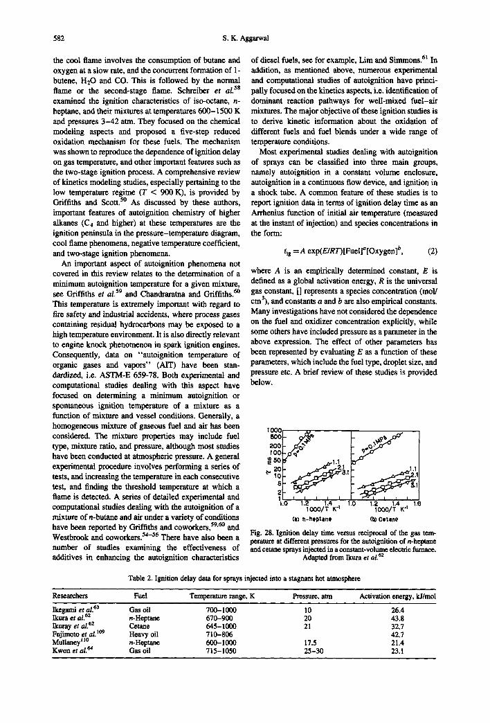
Most experimental studies dealing with autoignition of sprays can be classified into three main groups, namely autoignition in a constant volume enclosure, autoignition in a continuous flow device, and ignition in a shock tube. A common feature of these studies is to report ignition data in terms of ignition delay time as an Arrhenius function of initial air temperature (measured at the instant of injection) and species concentrations in the form:
tls =A exp(E/RT)[Fuel]a[Oxygen] b, (2)
where A is an empirically determined constant, E is defined as a global activation energy, R is the universal gas constant, [] represents a species concentration (mol/ cm3), and constants a and b are also empirical constants. Many investigations have not considered the dependence on the fuel and oxidizer concentration explicitly, while some others have included pressure as a parameter in the above expression. The effect of other parameters has been represented by evaluating E as a function of these parameters, which include the fuel type, droplet size, and pressure etc. A brief review of these studies is provided below.
Ioo¢ 5O0 2O0
O0
20 ~1o
I I.O 1.2 1.4 1.0 1.2 1.4 1.6
IO00/T K -I IO00/T K -1
(e) ~-heptane (b) Cetane
Fig. 28. Ignition delay time versus reciprocal of the gas tem- perature at different pressures for the autoignition of n-heptane and cetane sprays injected in a constant-volume electric furnace.
Adapted from Ikura et al. 62
Table 2. Ignition delay data for sprays injected into a stagnant hot atmosphere
Researchers Fuel Temperature range, K Pressure, arm Activation energy, kJ/mol
Ikegami et aL 63 Gas oil 700-1000 10 26.4 Ikura et aL 62 n-Heptane 670-900 20 43.8 Ikuray et al. 62 Cetane 645-1000 21 32.7 Fujimoto et al.l°9 Heavy oil 710-806 42.7 Mullaney[ Jo n-Heptane 600-1000 17.5 21.4 Kwon et al. ~4 Gas oil 715-1050 25-30 23.1
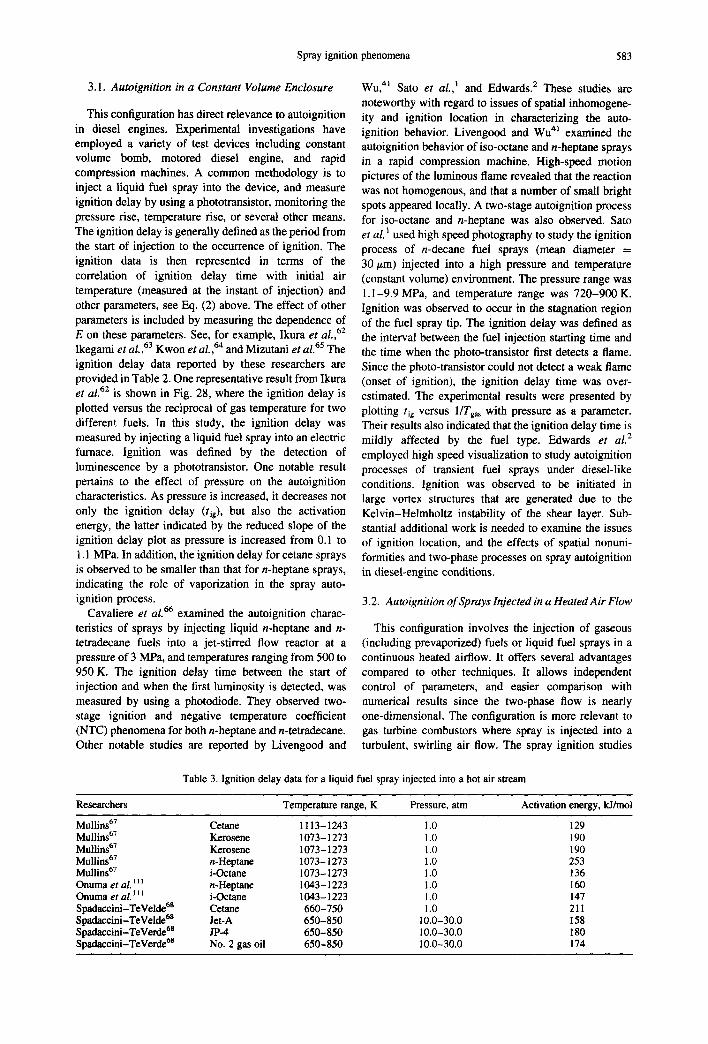
Spray ignition phenomena 583
3.1. A u t o i g n i t i o n in a C o n s t a n t V o l u m e E n c l o s u r e
This configuration has direct relevance to autoignition in diesel engines. Experimental investigations have employed a variety of test devices including constant volume bomb, motored diesel engine, and rapid compression machines. A common methodology is to inject a liquid fuel spray into the device, and measure ignition delay by using a phototransistor, monitoring the pressure rise, temperature rise, or several other means. The ignition delay is generally defined as the period from the start of injection to the occurrence of ignition. The ignition data is then represented in terms of the correlation of ignition delay time with initial air temperature (measured at the instant of injection) and other parameters, see Eq. (2) above. The effect of other parameters is included by measuring the dependence of E on these parameters. See, for example, Ikura e t al.,62 Ikegami et al. 63 Kwon et ai.,64 and Mizutani e t al. 6~ T h e
ignition delay data reported by these researchers are provided in Table 2. One representative result from Ikura et al. 62 is shown in Fig. 28, where the ignition delay is plotted versus the reciprocal of gas temperature for two different fuels. In this study, the ignition delay was measured by injecting a liquid fuel spray into an electric furnace. Ignition was defined by the detection of luminescence by a phototransistor. One notable result pertains to the effect of pressure on the autoignition characteristics. As pressure is increased, it decreases not only the ignition delay (tie), but also the activation energy, the latter indicated by the reduced slope of the ignition delay plot as pressure is increased from 0.1 to 1.1 MPa. In addition, the ignition delay for cetane sprays is observed to be smaller than that for n-heptane sprays, indicating the role of vaporization in the spray auto- ignition process.
Cavaliere e t al. 66 examined the autoignition charac- teristics of sprays by injecting liquid n-heptane and n- tetradecane fuels into a jet-stirred flow reactor at a pressure of 3 MPa, and temperatures ranging from 500 to 950 K. The ignition delay time between the start of injection and when the first luminosity is detected, was measured by using a photodiode. They observed two- stage ignition and negative temperature coefficient (NTC) phenomena for both n-beptane and n-tetradecane. Other notable studies are reported by Livengood and
Wu, 41 Sato et al., l and Edwards. 2 These studies are noteworthy with regard to issues of spatial inhomogene- ity and ignition location in characterizing the auto- ignition behavior. Livengood and Wu 41 examined the autoignition behavior of iso-octane and n-heptane sprays in a rapid compression machine. High-speed motion pictures of the luminous flame revealed that the reaction was not homogenous, and that a number of small bright spots appeared locally. A two-stage autoignition process for iso-octane and n-heptane was also observed. Sato et aL ~ used high speed photography to study the ignition process of n-decane fuel sprays (mean diameter = 30 tim) injected into a high pressure and temperature (constant volume) environment. The pressure range was 1.1-9.9 MPa, and temperature range was 720-900 K. Ignition was observed to occur in the stagnation region of the fuel spray tip. The ignition delay was defined as the interval between the fuel injection starting time and the time when the photo-transistor first detects a flame. Since the photo-transistor could not detect a weak flame (onset of ignition), the ignition delay time was over- estimated. The experimental results were presented by plotting rig versus 1/Tgas with pressure as a parameter. Their results also indicated that the ignition delay time is mildly affected by the fuel type. Edwards e t aL 2
employed high speed visualization to study autoignition processes of transient fuel sprays under diesel-like conditions. Ignition was observed to be initiated in large vortex structures that are generated due to the Kelvin-Helmholtz instability of the shear layer. Sub- stantial additional work is needed to examine the issues of ignition location, and the effects of spatial nonuni- formities and two-phase processes on spray autoignition in diesel-engine conditions.
3.2. Auto ign i t ion o f Sprays In j ec t ed in a H e a t e d A i r F l o w
This configuration involves the injection of gaseous (including prevaporized) fuels or liquid fuel sprays in a continuous heated airflow. It offers several advantages compared to other techniques. It allows independent control of parameters, and easier comparison with numerical results since the two-phase flow is nearly one-dimensional. The configuration is more relevant to gas turbine combustors where spray is injected into a turbulent, swirling air flow. The spray ignition studies
Table 3. Ignition delay data for a liquid fuel spray injected into a hot air stream
Researchers Temperature range, K Pressure, atm Activation energy, kJ/mol
Mullins 67 Cetane 1113-1243 1.0 129 Mullins 67 Kerosene 1073-1273 1.0 190 Mullins 67 Kerosene 1073 - 1273 1.0 190 Mullins 67 n-Heptane 1073-1273 1.0 253 Mullins 67 i-Octane 1073-1273 1.0 136 Onuma et aLi i z n-Heptane 1043-1223 1.0 160 Onuma et al. ~ ~ z i-Octane 1043-1223 1.0 147 Spadaceini-TeVelde 68 Cetane 660-750 1.0 211 Spadaceini-TeVelde 6s Jet-A 650-850 10.0- 30.0 158 Spadaccini-TeVerd¢ 6s JP-4 650-850 10.0-30.0 180 Spadaccini-TeVerd¢ 68 No. 2 gas oil 650-850 10.0-30.0 174
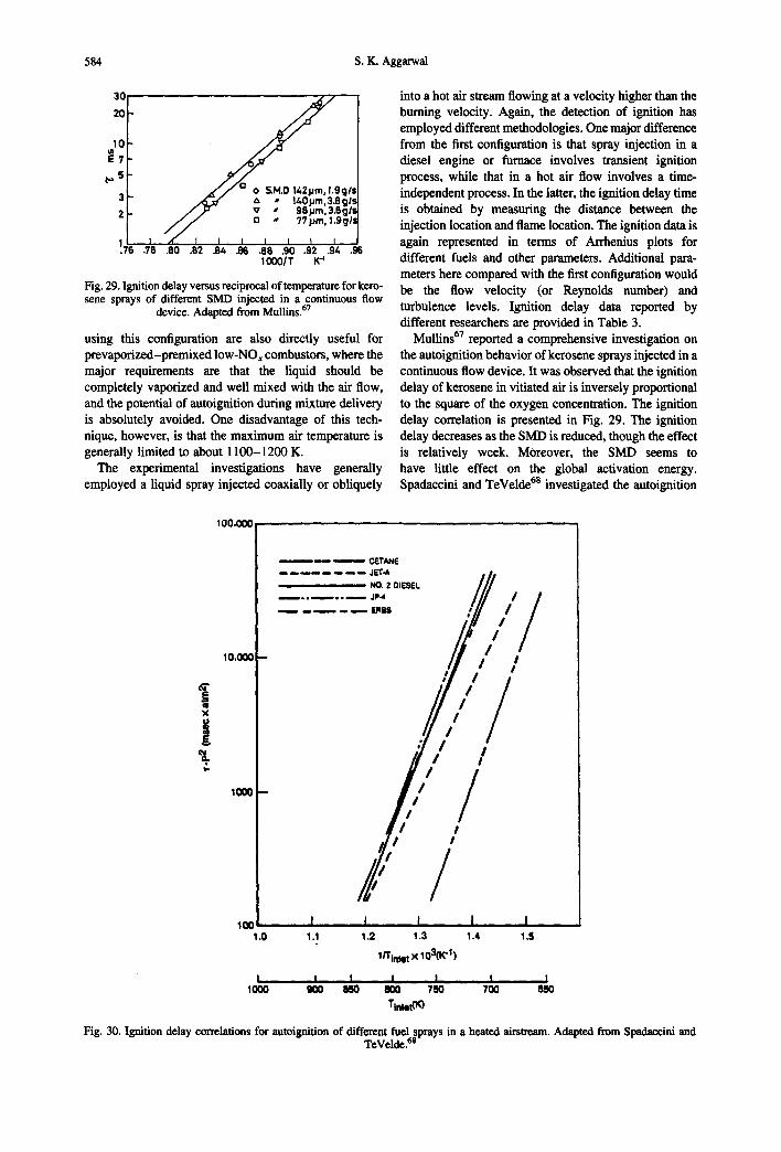
584 S.K. Aggarwal
30
20
1 0 E 7
3 ! 2 ~
I I I .7 .78
• , • l_4_0~m.3_.Sgt,. ~, , l : r v • 98JJm. 3.8g1'.
/ / a - 77pro. 1.ggL'
,4" I I I I I I I .80 .82 .S4 .156 .8e .90 .92 .9~. .g6
IO00]T K "1
Fig. 29. Ignition delay versus reciprocal of temperature for kero- sene sprays of different SMD injected in a continuous flow
device. Adapted from Mullins. 67
using this configuration are also directly useful for prevaporized-premixed low-NOx combustors, where the major requirements are that the liquid should be completely vaporized and well mixed with the air flow, and the potential of autoignition during mixture delivery is absolutely avoided. One disadvantage of this tech- nique, however, is that the maximum air temperature is generally limited to about 1100-1200 K.
The experimental investigations have generally employed a liquid spray injected coaxially or obliquely
into a hot air stream flowing at a velocity higher than the burning velocity. Again, the detection of ignition has employed different methodologies. One major difference from the first configuration is that spray injection in a diesel engine or furnace involves transient ignition process, while that in a hot air flow involves a time- independent process. In the latter, the ignition delay time is obtained by measuring the distance between the injection location and flame location, The ignition data is again represented in terms of Arrhenius plots for different fuels and other parameters. Additional para- meters here compared with the first configuration would be the flow velocity (or Reynolds number) and turbulence levels. Ignition delay data reported by different researchers are provided in Table 3.
Mullins ~7 reported a comprehensive investigation on the autoignition behavior of kerosene sprays injected in a continuous flow device. It was observed that the ignition delay of kerosene in vitiated air is inversely proportional to the square of the oxygen concentration. The ignition delay correlation is presented in Fig. 29. The ignition delay decreases as the SMD is reduced, though the effect is relatively week. Moreover, the SMD seems to have little effect on the global activation energy. Spadaccini and TeVelde es investigated the autoignition
I00.000
| X
|
10,000
lO00
10o 1.0
cLvrANE jLrr.A
, , NO. 2 DIESEL , ;P4
! I I I 1000 QO0 700 650
/ / t /
I I I I I 1.1 1.2 1.3 1.4 1.5
1/Tinle t x 103(K "I )
I I I 85O 800 7S0
Tinier(K)
Fig. 30. Ignition delay correlations for autoignition of different fuel sprays in a heated airstream. Adapted from Spadaccini and TeVelde.aS
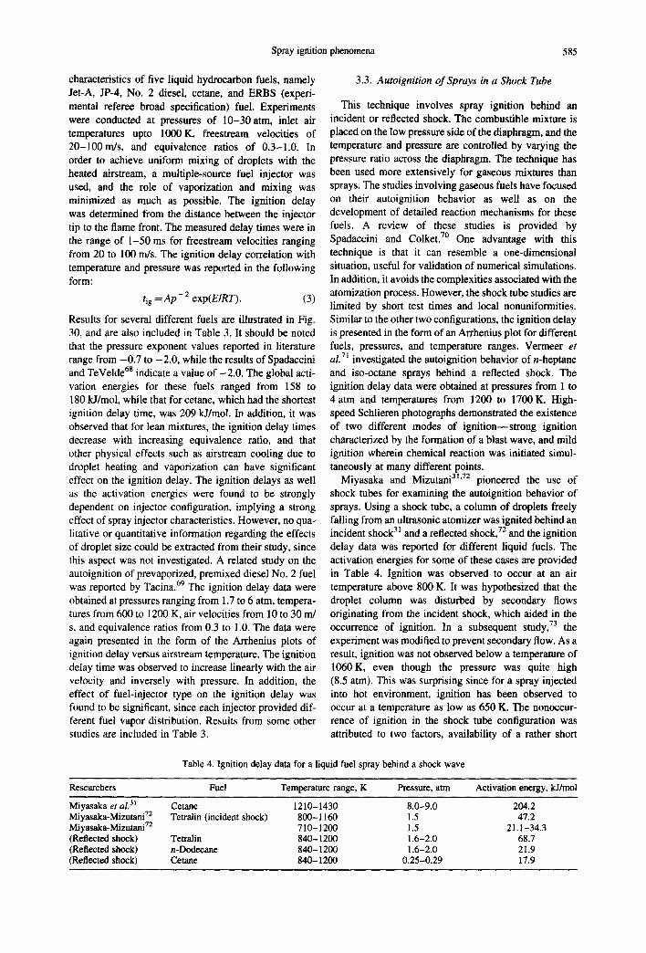
Spray ignition phenomena 585
characteristics of five liquid hydrocarbon fuels, namely Jet-A, JP-4, No. 2 diesel, cetane, and ERBS (experi- mental referee broad specification) fuel. Experiments were conducted at pressures of 10-30atm, inlet air temperatures upto 1000K, freestream velocities of 20-100m/s, and equivalence ratios of 0.3-1.0. In order to achieve uniform mixing of droplets with the heated airstream, a multiple-source fuel injector was used, and the role of vaporization and mixing was minimized as much as possible. The ignition delay was determined from the distance between the injector tip to the flame front. The measured delay times were in the range of 1-50 ms for freestream velocities ranging from 20 to 100 m/s. The ignition delay correlation with temperature and pressure was reported in the following form:
l ig ---~ A p - 2 exp(EIRT). (3)
Results for several different fuels are illustrated in Fig. 30, and are also included in Table 3. It should be noted that the pressure exponent values reported in literature range from -0.7 to -2.0, while the results of Spadaccini and TeVelde 6s indicate a value of -2.0. The global acti- vation energies for these fuels ranged from 158 to 180 kJ/mol, while that for cetane, which had the shortest ignition delay time, was 209 kJ/mol. In addition, it was observed that for lean mixtures, the ignition delay times decrease with increasing equivalence ratio, and that other physical effects such as airstream cooling due to droplet heating and vaporization can have significant effect on the ignition delay. The ignition delays as well as the activation energies were found to be strongly dependent on injector configuration, implying a strong effect of spray injector characteristics. However, no qua- litative or quantitative information regarding the effects of droplet size could be extracted from their study, since this aspect was not investigated. A related study on the autoignition of prevaporized, premixed diesel No. 2 fuel was reported by Tacina. 69 The ignition delay data were obtained at pressures ranging from 1.7 to 6 atm, tempera- tures from 600 to 1200 K, air velocities from 10 to 30 m/ s, and equivalence ratios from 0.3 to 1.0. The data were again presented in the form of the Arrhenius plots of ignition delay versus airstream temperature. The ignition delay time was observed to increase linearly with the air velocity and inversely with pressure. In addition, the effect of fuel-injector type on the ignition delay was found to be significant, since each injector provided dif- ferent fuel vapor distribution. Results from some other studies are included in Table 3.
3.3. Autoignition o f Sprays in a Shock Tube
This technique involves spray ignition behind an incident or reflected shock. The combustible mixture is placed on the low pressure side of the diaphragm, and the temperature and pressure are controlled by varying the pressure ratio across the diaphragm. The technique has been used more extensively for gaseous mixtures than sprays. The studies involving gaseous fuels have focused on their autoignition behavior as well as on the development of detailed reaction mechanisms for these fuels. A review of these studies is provided by Spadaccini and Colket. 7° One advantage with this technique is that it can resemble a one-dimensional situation, useful for validation of numerical simulations. In addition, it avoids the complexities associated with the atomization process. However, the shock tube studies are limited by short test times and local nonuniformities. Similar to the other two configurations, the ignition delay is presented in the form of an Arrhenius plot for different fuels, pressures, and temperature ranges. Vermeer et al. 71 investigated the autoignition behavior of n-heptane and iso-octane sprays behind a reflected shock. The ignition delay data were obtained at pressures from 1 to 4 atm and temperatures from 1200 to 1700 K. High- speed Schlieren photographs demonstrated the existence of two different modes of ignition--strong ignition characterized by the formation of a blast wave, and mild ignition wherein chemical reaction was initiated simul- taneously at many different points.
Miyasaka and Mizutani 31'72 pioneered the use of shock tubes for examining the autoignition behavior of sprays. Using a shock tube, a column of droplets freely falling from an ultrasonic atomizer was ignited behind an incident shock 31 and a reflected shock, 72 and the ignition delay data was reported for different liquid fuels. The activation energies for some of these cases are provided in Table 4. Ignition was observed to occur at an air temperature above 800 K. It was hypothesized that the droplet column was disturbed by secondary flows originating from the incident shock, which aided in the occurrence of ignition. In a subsequent study, 73 the experiment was modified to prevent secondary flow. As a result, ignition was not observed below a temperature of 1060K, even though the pressure was quite high (8.5 atm). This was surprising since for a spray injected into hot environment, ignition has been observed to occur at a temperature as low as 650 K. The nonoccur- rence of ignition in the shock tube configuration was attributed to two factors, availability of a rather short
Table 4. Ignition delay data for a liquid fuel spray behind a shock wave
Researchers Fuel Temperature range, K Pressure, atm Activation energy, kJ/mol
Miyasaka et aL 3~ Cetane 1210-1430 8.0-9.0 204.2 Miyasaka-Mizutani 72 Tetralin (incident shock) 800-1160 1.5 47.2 Miyasaka-Mizutani 72 710-1200 1.5 21.1-34.3 (Reflected shock) Tetralin 840-1200 1.6-2.0 68.7 (Reflected shock) n-Dodecane 840-1200 1.6-2.0 21.9 (Reflected shock) Cetane 840-1200 0.25-0.29 17.9
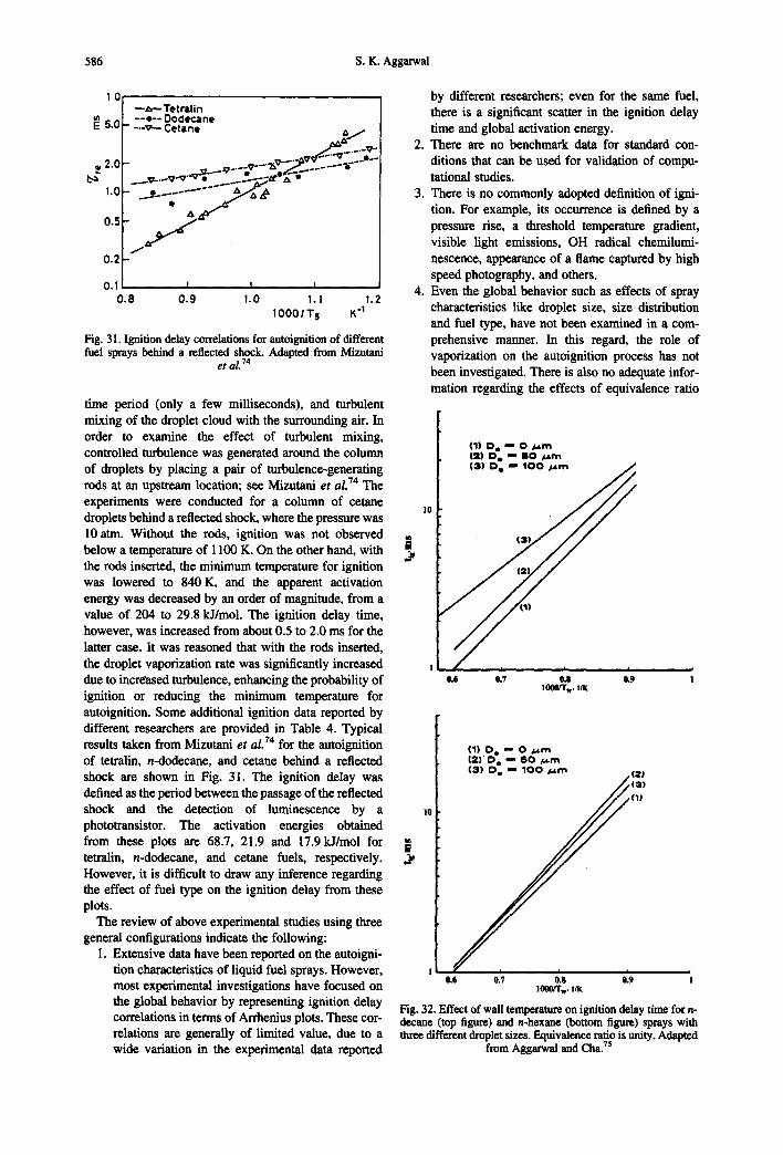
586 S.K. Aggarwal
10
~ 5.0
2.0
1.0
0.5
- - , , - - Tetra l in - - o - - Dodecane - . - v - - Cetane ~ /
......~-.--V'~ ' ' v • . . . . . ---~..;~" A • . _ . . . . . . . . . . . a/,,Z-- ~,
0.2
0.1 0 .8
I I I
0.9 1.0 1.1 1.2 1 0 0 0 / T 5 K "t
Fig. 31. Ignition delay correlations for autoignition of different fuel sprays behind a reflected shock. Adapted from Mizutani
e t al. 74
time period (only a few milliseconds), and turbulent mixing of the droplet cloud with the surrounding air. In order to examine the effect of turbulent mixing, controlled turbulence was generated around the column of droplets by placing a pair of turbulence-generating rods at an upstream location; see Mizutani et al. 74 T he
experiments were conducted for a column of cetane droplets behind a reflected shock, where the pressure was 10 arm. Without the rods, ignition was not observed below a temperature of 1100 K. On the other hand, with the rods inserted, the minimum temperature for ignition was lowered to 840 K, and the apparent activation energy was decreased by an order of magnitude, from a value of 204 to 29.8 kJ/mol. The ignition delay time, however, was increased from about 0.5 to 2.0 ms for the latter case. It was reasoned that with the rods inserted, the droplet vaporization rate was significantly increased due to increased turbulence, enhancing the probability of ignition or reducing the minimum temperature for autoignition. Some additional ignition data reported by different researchers are provided in Table 4. Typical results taken from Mizntani et al. TM for the autoignition of tetralin, n-dodecane, and cetane behind a reflected shock are shown in Fig. 31. The ignition delay was defined as the period between the passage of the reflected shock and the detection of luminescence by a phototransistor. The activation energies obtained from these plots are 68.7, 21.9 and 17.9 ~ /mol for tetralin, n-dodecane, and cetane fuels, respectively. However, it is difficult to draw any inference regarding the effect of fuel type on the ignition delay from these plots.
The review of above experimental studies using three general configurations indicate the following:
1. Extensive data have been reported on the autoigni- tion characteristics of liquid fuel sprays. However, most experimental investigations have focused on the global behavior by representing ignition delay correlations in terms of Arrhenius plots. These cor- relations are generally of limited value, due to a wide variation in the experimental data reported
by different researchers; even for the same fuel, there is a significant scatter in the ignition delay time and global activation energy.
2. There are no benchmark data for standard con- ditions that can be used for validation of compu- tational studies.
3. There is no commonly adopted definition of igni- tion. For example, its occurrence is defined by a pressure rise, a threshold temperature gradient, visible light emissions, OH radical chemilumi- nescence, appearance of a flame captured by high speed photography, and others.
4. Even the global behavior such as effects of spray characteristics like droplet size, size distribution and fuel type, have not been examined in a com- prehensive manner. In this regard, the role of vaporization on the autoignition process has not been investigated. There is also no adequate infor- mation regarding the effects of equivalence ratio
l0
(1) D e '," 0 ~ t m ( 2 ) D e " B O ~t~.m ( 3 ) D e " 1 0 0 ~ . m J , J /
J Z /
0.6 0.7 0.8 0.9 1000/T w, I/K
(1) D e " 0 / . trn | 2 ) ' 0 e m, 8 0 / .~m ( 3 ) D e "" 1 0 0 ~ . m . (21
/ ~ ( 3 )
(1)
10
| #
0.6 0.7 0.S 0.9 ! 1000/Two IlK
Fig. 32. Effect of wall temperature on ignition delay time for n- decane (top figure) and n-hexane (bottom figure) sprays with three different droplet sizes. Equivalence ratio is unity. Adapted
from Aggarwal and Cha. 7s

Spray ignition phenomena 587
and mixture quality (amount of fuel vaporized) on the autoignition characteristics.
5. The effects of flow inhomogeneities, transport pro- cesses, and turbulence have not been studied. The role of vortex structures, that are directly related to spatial nonuniformities and turbulence, has not been examined, neither are issues related to the ignition location or flame kernel in autoignition situations.
3.4. Theoretical and Computational Studies on Autoignition of Sprays
Theoretical investigations of autoignition phenomena range from simple phenomenological models to transient one-dimensional models using single-step and multi-step mechanisms, and to multidimensional models employing single-step as well as multi-step reduced mechanisms. The phenomenological models have generally been developed for specific applications to explain exper- imentally observed phenomena. See, for example, Sato et al. 1 Several studies have also been conducted employing transient, one-dimensional, two-phase models. Aggarwal and Cha 75 used such a model with global one-step mechanism to study the ignition of an initially quiescent mist ignited by a heated wall. Although, the configura- tion did not simulate an autoignition situation, the simulations focused on some common features between external-source ignition and spontaneous ignition. Results were presented in terms of ignition delay time as a function of the hot wall temperature. As shown in Fig. 32, the effect of wall temperature on ignition delay can be represented in the Arrhenius form, with constants depending on the droplet size and fuel type. Also, it is apparent that the effect of vaporization is more significant for n-decane compared to n-hexane. The predictions showed good agreement with the available experimental data.
Guthei125 also employed a transient, one-dimensional model to investigate the autoignition behavior of a dilute methanol spray in a constant volume combustor. A uniform, initially quiescent spray in a cylindrical tube was simulated. The computational model of Aggarwal and Sirignano 15 was extended to include a detailed kinetics mechanism for the oxidation of methanol, comprising 23 species and 168 reactions. Another difference was that the cited work considered a planar geometry, whereas Gutheil's study 25 focused on the autoignition behavior in a cylindrical geometry. Internal droplet heating was included using a infinite- conductivity model. Two different ignition criteria were employed; the slope of the temperature profile (plotted versus time) showing a dramatic increase, and the concentration of hydroxyl radical reaching the maximum value. Effects of gas temperature, overall equivalence ratio, droplet size, initial fuel vapor concentration and pressure were examined. The parametric study yielded several interesting results. For example, it was shown that the ignition delay time (tig) for a homogeneous mixture of methanol vapor and air at 1500 K is 0.154 ms,
g
J 1800 1750 1700 1650 1600 1550 1500 1450 1400 , , ' . , . ' . , . J , . , I . . , l l l , l l . l l l l . I
0.0 0.2 0.4 0.6 0.8 1.0 1.2 1.4 1.6 t (ms)
Fig. 33. Temporal variation of gas temperature during the spray autoignition process for different fuels. Equivalence ratio is
unity. Adapted from Gutheil. 26
370 360 n-ocUme .....................................
~ 350340 /'" ...'"" ............... ~n'heptma¢
~ 330 """ . . . . 320
~' 310 300 "~, m¢lh~omethanol ethanol 290 . . . . . . , , , . , _ l . . . . . . . . . . . . . . . . . .
0.0 0.2 0.4 0.6 0.8 1.0 1.2 1.4 1.6 t (ms)
Fig. 34. Temporal variation of droplet surface temperature dur- ing the spray autoignition process for different fuels. Equiv- alence ratio is unity and initial gas temperature is 1500K.
Adapted from Gutheil. 2~
+ . o
0.7
! o0 . . . . . . . . . . . . . . . ' 7 ? . . . . . . . . 0,0 0.2 0.4 0.6 0.8 1.0 1.2 1.4 1.6
t (ms)
Fig. 35. Temporal variation of normalized droplet surface area during the spray autoignition process for different fuels. Equiv- alence ratio is unity and initial gas temz~erature is 1500 K.
Adapted from Gutheil.
while that for the corresponding monodisperse spray (droplet diameter of 50 gm) is 0.5 ms, implying that the ignition process is vaporization-controlled even at a relatively high temperature. Also, for the heterogeneous case, the ignition time decreased considerably as the gas temperature was reduced from 1700 to 1500 K, indi- cating that the ignition process is governed by both vaporization and chemical kinetics. Results for a bidisperse spray indicated that the ignition process is controlled by the smaller-size droplets. The numerical study also observed the existence of an optimum droplet size and equivalence ratio corresponding to a minimum ignition delay time. This is an interesting result since Aggarwal and Sirignano Is observed similar behavior for

588 S.K. Aggarwai
i J
0.020
°1 /i o.o~s n2~,~ ; ! ~....co2
i 0.010 i I * I
/ ' l / " ! ~ .CO @." ,/'/ OH o.oo5 r.,~,,,,,~ .:;..~, ;........ \ . /
0.ooo 0.00 0.40 0.80 1.20 1,60 2.00
t (ms)
Fig. 36. Temporal variation of the mass fractions of several species during the ignition process. The instant of ignition can be defined by monitoring the mass fraction of an intermediate species, for example CO. Adapted from Gutheil. 26
hydrocarbon (n-heptane and n-decane) fuel sprays SO- Tw= 1500 K ignited by a hot surface. Moreover, the numerical model of Aggarwal and Sirignano z5 considered planar ~ m 1.0 geometry and employed a global one-step mechanism, 40- I ~ o n e ~ 37.5 while that of Gutheil z5 considered cylindrical geometry and a detailed mechanism for methanol-air mixtures. This implies that the existence of an optimum droplet 2 6 ~ ~ j size and equivalence ratio is a more general phenom- 30- enon, since its validity is shown for different fuels and ~ CI2 H geometries, for both autoignition and the external- , ~ . ~ ~ . ~ i ~ ~ 8 . 7 source-ignition situations, and by using global and 20- detailed mechanisms.
In a subsequent study, Guthei126 extended the numerical model to autoignition of methanol, ethanol, 10- ~ ° r l ~ . . ~ ' ~ ~ n-heptane, and n-octane sprays. The model again ~ ~ 1"116 considered an initially quiescent, uniform spray in a constant-volume cylindrical enclosure. The detailed 0 mechanisms considered 23 species and 168 reactions o 7o 10o ' ' 160 200 for methanol, 38 species and 342 reactions for ethanol as SMD,/,Lm C2 chemistry was added, 73 species and 682 reactions for n-heptane, and 79 species and 762 reactions for n-octane. Fig. 37. Effect of SMD on ignition delay for four different fuels. The ignition delay for each case was determined from the Adapted from Mawid and Aggarwal. 42 slope of the temperature profile. Some results from the cited study, illustrating the effects of fuel and spray temperature for alkane fuels, while it attains its wet-bulb properties on the spray ignition behavior, are given in temperature for ethanol and methanol fuels. This is Figs 33-35. The gas temperature is 1500 K, the pressure apparently caused by two factors. First, the heat of is 1 atm, the overall equivalence ratio is unity, and the vaporization for ethanol and methanol is about three droplet diameter is 50 #m. For these conditions, the times higher than that for n-heptane and n-octane fuels. predicted ignition delay times are 0.1, 0.2, 0.5, and This makes the droplet temperature rise more slowly for 4,7 ms for n-heptane, n-octane, ethanol, and methanol the alcohol fuels, reducing the vaporization rate as spray respectively. These values can be deduced from indicated in Fig. 35, and increasing the ignition delay. Fig. 33, which depicts the temporal variation of gas Second, the heat of combustion is higher for alkanes, temperature for different fuels. As indicated, the gas which accelerates the heat release rate and the occur- temperature first decreases due to heat transfer from the rence of ignition. Another important observation is that gas phase to the droplets, and then increases after the the spray ignition process is strongly influenced by the occurrence of ignition. The vast difference in the ignition liquid fuel properties such as fuel volatility and heat of delay times can be explained by examining the temporal vaporization, implying that vaporization plays an variation of droplet temperature depicted in Fig. 34. The important role in the ignition process even at a relatively plots in Fig. 34 indicate that at the time of ignition, the high gas temperature. Regarding the existence of droplet temperature is considerably below the wet-bulb optimum droplet sizes for a minimum ignition delay
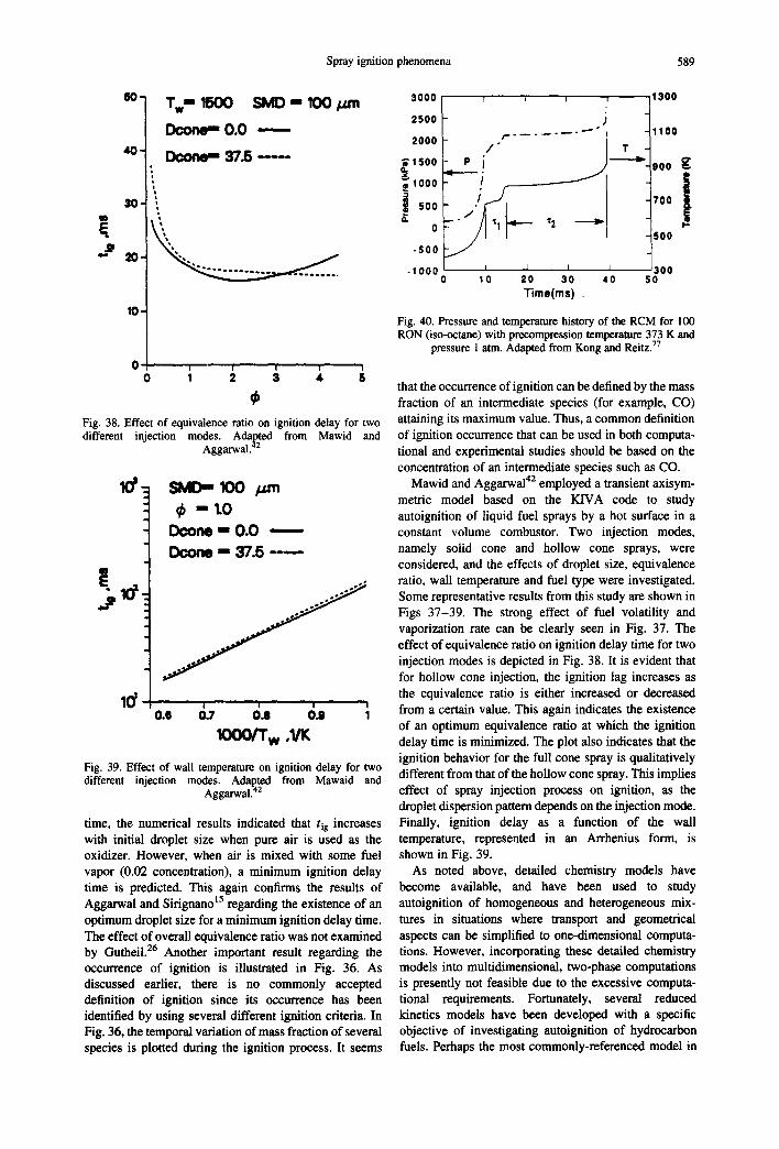
Spray ignition phenomena 589
so 1 Tw" 1500 SMD -- 100 bun sooo 2500
| Dcone, , ,O.O 2000
a T z --- ; , 500
~IOOO
-500
.IOOO
10-
0 i ! I o I 3 , Fig. 38. Effect of equivalence ratio on ignition delay for two different injection modes. Adapted from Mawid and
Aggarwal. 42
lo' 1 SMD- mO I~ m1.0 Dcone - 0.0 ,
D¢on~D -- 37.5 -----
IO00/T w ,1~
Fig. 39. Effect of wall temperature on ignition delay for two different injection modes. Adapted from Mawaid and
Aggarwal. 42
time, the numerical results indicated that rig increases with initial droplet size when pure air is used as the oxidizer. However, when air is mixed with some fuel vapor (0.02 concentration), a minimum ignition delay time is predicted. This again confirms the results of Aggarwal and Sirignano 15 regarding the existence of an optimum droplet size for a minimum ignition delay time. The effect of overall equivalence ratio was not examined by Gutheil. 26 Another important result regarding the occurrence of ignition is illustrated in Fig. 36. As discussed earlier, there is no commonly accepted definition of ignition since its occurrence has been identified by using several different ignition criteria. In Fig. 36, the temporal variation of mass fraction of several species is plotted during the ignition process. It seems
i t:::: / / , . . . . . . . . - ~ °
P i ~ 1700 I . -
i I . 500
~300 10 20 30 40 50
Time(ms)
Fig. 40. Pressure and temperature history of the RCM for 100 RON (iso-octane) with precompression temperature 373 K and
pressure 1 atm. Adapted from Kong and Reitz. 77
that the occurrence of ignition can be defined by the mass fraction of an intermediate species (for example, CO) attaining its maximum value. Thus, a common definition of ignition occurrence that can be used in both computa- tional and experimental studies should be based on the concentration of an intermediate species such as CO.
Mawid and Aggarwa142 employed a transient axisym- metric model based on the KIVA code to study autoignition of liquid fuel sprays by a hot surface in a constant volume combustor. Two injection modes, namely solid cone and hollow cone sprays, were considered, and the effects of droplet size, equivalence ratio, wall temperature and fuel type were investigated. Some representative results from this study are shown in Figs 37-39. The strong effect of fuel volatility and vaporization rate can be clearly seen in Fig. 37. The effect of equivalence ratio on ignition delay time for two injection modes is depicted in Fig. 38. It is evident that for hollow cone injection, the ignition lag increases as the equivalence ratio is either increased or decreased from a certain value. This again indicates the existence of an optimum equivalence ratio at which the ignition delay time is minimized. The plot also indicates that the ignition behavior for the full cone spray is qualitatively different from that of the hollow cone spray. This implies effect of spray injection process on ignition, as the droplet dispersion pattern depends on the injection mode. Finally, ignition delay as a function of the wall temperature, represented in an Arrbenius form, is shown in Fig. 39.
As noted above, detailed chemistry models have become available, and have been used to study autoignition of homogeneous and heterogeneous mix- tures in situations where transport and geometrical aspects can be simplified to one-dimensional computa- tions. However, incorporating these detailed chemistry models into multidimensional, two-phase computations is presently not feasible due to the excessive computa- tionai requirements. Fortunately, several reduced kinetics models have been developed with a specific objective of investigating autoignition of hydrocarbon fuels. Perhaps the most commonly-referenced model in
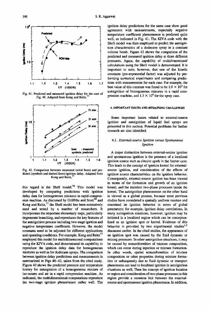
590 S.K. Aggarwal
i
i I i I
P ~ " ~ I
/ /
I I I I I
I . I 1 . 2 1 . 3 1 . 4 I . S 1 . 6 1 . 7
I/T (IO00/K)
Fig. 41. Predicted and measured ignition delay for the case of Fig. 40. Adapted from Kong and Reitz. 77
ignition delay predictions for the same case show good agreement with measurements, especially negative temperature coefficient phenomenon is predicted quite well, as indicated in Fig. 41. The KIVA code with the Shell model was then employed to predict the autoigni- tion characteristics of a dodecane spray in a constant volume bomb. Figure 42 shows the comparison of the predicted and measured ignition delay at three different pressures. Again, the capability of multidimensional calculations using the Shell model is demonstrated, It is important to note, however, that one of the kinetic constants (pre-exponential factor) was adjusted by per- forming numerical experiments and comparing predic- tions with measurements for each case. For example, the best value of this constant was found to be 1.9 x 10⁴ for autoignition of homogeneous mixtures in a rapid com- pression machine, and 1.3 × 10⁶ for the spray case.
I I I I
11 arm
J 21 arm 31 arm
i;
• ymbols: predicted 1 1 I I I
1.I 1.2 1.3 1.4 1.5 1.6 I/T O000/K)
Fig. 42. Comparison between measured (solid lines) and pre- dicted (symbols and dashed lines) ignition delay. Adapted from
Kong and Reitz. 77
this regard is the Shell model. 76 This model was developed by comparing predictions with ignition delay data for homogeneous mixtures in rapid compres- sion machine. As discussed by Griffiths and Scott 5° and Kong and Reitz, 77 the Shell model has been extensively used and tested by a number of researchers. It incorporates the important elementary steps, particularly degenerate branching, and reproduces the key features of the autoignition process including two-stage ignition and negative temperature coefficient. However, the model constants need to be adjusted for different applications and operating conditions. For example, Kong and Reitz 77 employed this model for multidimensional computations using the KIVA code, and demonstrated its capability to reproduce the ignition delay data for homogeneous mixtures as well as for dodecane sprays. The comparison between ignition delay predictions and measurements is summarized in Figs 40-42, taken from the cited study. Figure 40 shows the predicted pressure and temperature history for autoignition of a homogeneous mixture of iso-octane and air in a rapid compression machine. As indicated, the multidimensional computations reproduce the two-stage ignition phenomenon rather well. The
4. IMPORTANT ISSUES AND REMAINING CHALLENGES
Some important issues related to external-source ignition and autoignition of liquid fuel sprays are presented in this section. Potential problems for further research are also identified.
4.1. External-source Ignition versus Spontaneous Ignition
A major distinction between external-source ignition and spontaneous ignition is the presence of a localized ignition source such as electric spark in the former case. This leads to the concept of ignition kernel for external- source ignition, and consideration of the effects of ignition source characteristics on the ignition behavior. Consequently, external-source ignition has been viewed in terms of the formation and growth of an ignition kernel, and the transient two-phase processes inside the kernel. The autoignition phenomenon on the other hand is viewed as a global process, because most previous studies have considered a spatially uniform mixture and examined its ignition behavior in terms of global parameters; for example, ignition delay correlations. In many autoignition situations, however, ignition may be initiated in a localized region which can be conceptua- lized as an ignition spot or kernel. Evidence of this behavior is provided by two experimental studies 1'2 discussed earlier. In the cited studies, the appearance of an ignition spot was caused by the fluid dynamic or mixing processes. In other autoignition situations, it may be caused by nonuniformities of mixture composition, which can occur during injection or mixture formation. In other words, spatial nonuniformities of mixture composition or other properties during mixture forma- tion or subsequently due to fluid dynamic or transport phenomena can lead to localized ignition in autoignition situations as well, Then the concept of ignition location or region and consideration of two-phase processes in this region provide a common link between the external- source and spontaneous ignition phenomena. In addition,
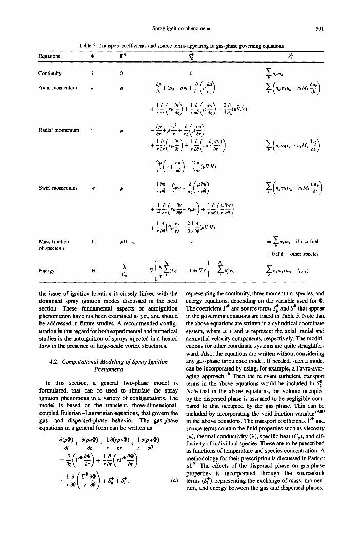
Spray ignition phenomena
Table 5. Transport coefficients and source terms appearing in gas-phase governing equations
591
Equations 4, 1 "i S~g
Continuity 1 0
Axial momentum u /z
Radial momentum v
Swirl momentum w
Mass fraction Yi pDi-N, of species i
Energy H Cv
0 Z nkgnk k
_ Opoz -'1- (O0 - P)g + -~Z t It ~Z) nktht<uk -- nkMk
1 0 { Ov'~ 1 0 { Ow'~ 20 VIi + - - - rli-- rOr t Oz)+r~tI~Z)--'30-~Z It " )
w 2 a ( au~ orClP "l- P -r" -t- "~Z t l iar)
1 Of Ov'~ 1 Of O(w/r)'~ ~'{nkthkv,_nkM dvk\ + rZt'7;) +
2~ {v Ow\ 2 a - 7 ( + -
lap ~vw+O( l iOu) ~(n.tthl<wk-- nkMk --~-)dwk'~ roe ~t,7~)
, o : ov \ l _ 0 ( e 0 w ] + -~-~rtr#~--rlxw) + raO\r 00/
1 O / v~ 21 0 V V + r ~ t E ~ r ) - ~r0~(0/z . )
~'~i = Z nkrhk if i = fuel k
= 0 i f i = other species
Ns ~[)%~(LeZI-I)Hi~Yi -~l h~l~i L CP 1 Z nkthk(hfs --/k,eff)
k
the issue of ignition location is closely linked with the dominant spray ignition modes discussed in the next section. These fundamental aspects of autoignition phenomenon have not been examined as yet, and should be addressed in future studies. A recommended config- uration in this regard for both experimental and numerical studies is the autoignition of sprays injected in a heated flow in the presence of large-scale vortex structures.
4.2. Computational Modeling of Spray Ignition Phenomena
In this section, a general two-phase model is formulated, that can be used to simulate the spray ignition phenomena in a variety of configurations. The model is based on the transient, three-dimensional, coupled Eulerian-Lagrangian equations, that govern the gas- and dispersed-phase behavior. The gas-phase equations in a general form can be written as
O(O~) O(ou~)1 O(rpv~) 1 O(Ow~) Ot 4 - ~ + r ~r t-r O0
=L(r' 5 oz\ a z } + ! ~ ( r r ' ~ r )
+ rO0\ r 00) +S~I +S~I, (4)
representing the continuity, three momentum, species, and energy equations, depending on the variable used for ,I,. The coefficient F ¢ and source terms S~g and S~ that appear in the governing equations are listed in Table 5. Note that the above equations are written in a cylindrical coordinate system, where u, v and w represent the axial, radial and azimuthal velocity components, respectively. The modifi- cations for other coordinate systems are quite straightfor- ward. Also, the equations are written without considering any gas-phase turbulence model. If needed, such a model can be incorporated by using, for example, a Favre-aver- aging approach. 7s Then the relevant turbulent transport terms in the above equations would be included in S~g. Note that in the above equations, the volume occupied by the dispersed phase is assumed to be negligible com- pared to that occupied by the gas phase. This can be included by incorporating the void fraction variable 79'8° in the above equations. The transport coefficients F i and source terms contain the fluid properties such as viscosity (#), thermal conductivity (X), specific heat (Cp), and dif- fusivity of individual species. These are to be prescribed as functions of temperature and species concentration. A methodology for their prescription is discussed in Park et aL 91 The effects of the dispersed phase on gas-phase properties is incorporated through the source/sink terms (S~'l), representing the exchange of mass, momen- tum, and energy between the gas and dispersed phases.

592 S.K. Aggarwal
The spray or liquid-phase properties can be rep- resented by using either an Eulerian or a Lagrangian formulation. A comprehensive discussion of these two formulations is given in Sirignano. 23 The Eulerian formulation employs the concept of continuum, such that a liquid-phase property at a point in time and space is assumed to represent the average value over many droplets in the neighborhood of that point. Then, the liquid-phase properties are governed by hyperbolic partial differential equations. Clearly, the approach is meaningful when the resolution is needed on a scale that is large compared with the average spacing between droplets. In the Lagrangian formulation, on the other hand, a spray is represented by a discrete number of "individual" droplets that are distinguished by their initial location, size, and velocity. The liquid-phase equations are then calculated by tracking these droplets, or following their trajectories and vaporization histories, which are governed by ordinary differential equations. This approach is useful when the phenomenon of interest has a scale smaller than the average distance between droplets. The spray ignition phenomena, especially that concerning external source ignition, occurs on the scale of the droplet spacing. For example, in the ignition of spray by an electric spark, the spark gap 21 is typically of the order of a millimeter. In spray ignition involving hot bodies, the thermal layer thickness 18 is again comparable to the average droplet spacing. Consequently, most computational studies dealing with spray ignition have employed the Lagrangian formulation. It should be noted, however, that there may be spray ignition situations, where an Eulerian formulation is more useful. These may include autoignition and external source ignition of sprays at pressures approaching critical or supercritical conditions, where the average droplet spacing may become smaller than the typical ignition length scale. This issue has not been examined in previous numerical studies of spray ignition.
Using the Lagrangian approach, the liquid-phase equations are written for the trajectory and vaporization history of each droplet group, which may represent a single droplet or a group of droplets. In order to keep the computational time manageable, a characteristic approach is often employed, 23'77 such that each char- acteristic or droplet group represents a finite number of droplets. In an axisymmetric simulation, for example, a characteristic would represent the number of droplets per unit width in the azimuthal direction, and the liquid- phase properties would be averaged over the azimuthal width. The equations governing the temporal variation of position, velocity, and size of each droplet group in a cylindrical coordinate system may be written as:
dxk - ~ - = uk (5)
dYk " ~ - ~ V k
dZk ~ W k dt
where
Re k
_ = du dr 3CD ,IV_VkI<u_U,) g <6)
dvk 3CDOg V VkI(V--Vk)+ w2 d---'~ = 4dkOk -- Yk
CD VkW k dWk = 0glV-- VkI(W-- wk) (7) dt '+ak0k Yk
dd__~k = 2thk" dt ok '
2",112 ( u - u k T + ( v - v ' ) 2 + ( w - w k ) I dk
/Zg
(9)
The following expressions 78 may be employed for cal- culating the rates of heat and mass transport between the droplet and the gas
hdk 2(Np/Le)In(1 + B) (I0) -'~-= (I +B) I/t~ - 1
:n "d k k =2Ns ln(1 +B), (11) oD
where B is the Spalding transfer number given by
B = (Y~s - YF~)I(I - YFs) (12)
and Np and Ns, corrective factors accounting for the convective effect on heat and mass transfer, may be cal- culated using semi-empirical relations 7s
0.278Re~/Z(Pr or Sc) I/3
Np or Ns = I + (I + 1.2321(Rek(Pr or Sc)4/3) I/2" (13)
Major assumptions employed in writing the droplet equations are: (i) spherically-symmetric, quasi-steady droplet vaporization with convective effects represented by the semi-empirical correlations; (ii) single- component fuel; and Off) quasi-steady drag equation with negligible mass transfer, flow nonuniformity and transient effects on the droplet drag. In order to extend the spray ignition model to high pressures and multi- component fuels, various modifications to these equa- tions have been proposed, s°-s4 For example, modifications needed to extend the model to multi- component fuel sprays are given in Aggarwal ~ and Abramzon and Sirignano. 84 The effects of blowing and flow nonuniformity on the droplet drag are discussed in Abramzon and Sirignano 84 and Bellan and Harstad. I°4 Also, improved correlations 84 should be employed to account for the convective effects, especially at higher droplet Reynolds numbers. The effects of pressure on spray ignition phenomena are discussed in the next section.

Spray ignition phenomena 593
In order to complete the solution, the temperature and fuel mass fraction at the droplet surface must be known. The two equations used to solve for these quantities are provided by the fuel vapor pressure relationship and the liquid-phase energy equation in the droplet interior. The vapor pressure relationship has the form
Y~s =f(Ts, P, }'is). (14)
One such commonly used equation is the Clausius-Cla- peyron relation, s2 Several other equations are given in Reid e t al. s~ T h e transient liquid-phase processes have been represented by using different droplet heating models. 17"23 Since the droplet surface temperature is an important parameter for the spray ignition phenomena, a realistic model for its prediction is essential for the development of a reliable spray ignition model. Here, an effective diffusion model ~ is recommended for cal- culating the droplet surface temperature. In this model, the transient heat transport within the droplet is rep- resented by the unsteady heat diffusion equation in a spherically symmetric geometry. The liquid thermal con- ductivity is modified, however, to account for the liquid motion inside the droplet. For multicomponent fuel sprays, the liquid mass transport, which is often the rate-controlling process, can also be represented by the effective diffusion model, details of which can be found in Abramzon and Sirignano. s4 Another important con- sideration in the development of a reliable spray ignition model is the inclusion of variable liquid- and gas-phase thermophysical properties. For subcritical pressures, these properties are prescribed as functions of tempera- ture and species concentration, while for pressures near critical and supercritical, they also become functions of pressure. A methodology to compute these properties can be found in Aggarwal e t al. s2 and Stengele e t al. 83
The two-phase equations described above can be employed for simulating both the external source ignition and the autoignition phenomena in a given flow configuration. For the former, a realistic representa- tion of the external ignition source is needed in the simulation. For the latter, an appropriate geometric and flow model needs to be included, depending upon the autoignition situation under consideration, i.e. autoigni- tion in a constant-volume enclosure, in a uniform flow, or in a shock tube. In addition, a realistic reduced- chemistry or detailed-chemistry model is needed, depending upon the liquid fuel used. Different chemi- cal-kinetics models used in the numerical simulation of autoignition phenomena have been discussed in Section 3. For external source ignition, the reduced -29 and detailed-chemistry 26 models have been employed only for simplified one-dimensional configurations. More realistic reduced mechanisms sS's6 for the ignition of heptane-alr mixtures have become available recently. In future investigations, the reduced and detailed mechan- isms should be employed for the simulation of external- source ignition phenomena in more realistic configura- tions. These investigations should also focus on fluid dynamic aspects, examining the effects of flow inhomo- geneities and transport processes on ignition. In this
regard, some notable studies are due to Law and coworkers, 87'88 who examined the ignition characteris- tics of several gaseous, nonpremixed, fuel-air mixtures in a counterflow configuration.
There are also important numerical and physical considerations with regard to a numerical solution of the above two-phase equations. For a given configuration, specification of the initial two-phase properties is an important issue. In particular, specification of the initial dispersed-phase properties is not a trivial task, and has a profound influence on the prediction of ignition characteristics. For a given overall equivalence ratio, it requires specifying the initial droplet size and velocity distributions, based on some analytical expressions or experimental data. As discussed earlier, a Lagrangian formulation implies a probabilistic character ~5"23 for the spray ignition phenomena, since the ignition length scale is comparable to the average droplet spacing. The probabilistic nature can be accounted for by specifying the initial liquid-phase properties in a deterministic manner, and then computing the ignition probability. As discussed earlier, the implication is that the minimum ignition energy can not precisely be known in a practical spray, since it depends on the distance from heat source to the nearest droplet. For the same reason, the optimum droplet size or equivalence ratio can not be determined precisely. Other important issues here are the specifica- tion of an optimum grid for the solution of the gas-phase equations, and the selection of an "optimum" algorithm for solving the two-phase equations. The grid system should be optimized so as to accurately resolve scales associated with a given external ignition source. Several methodologies based on the explicit and implicit formulations, and the finite-difference and finite- volume discretizations of the gas-phase equations have been reported in literature, s9'9° In general, due to the small time scales of the ignition process, an implicit finite-volume discretization is recommended.
The ordinary differential equations governing the trajectory and size history of each droplet group can be solved by using a second-order Runge-Kutta method. Generally, it is not advantageous to use a higher-order method for the droplet equations, since the temporal time step for integrating these equations is determined by physical rather than numerical considerations, i.e. by time scales associated with the ignition process and the droplet heating and vaporization rates. Also, the time step for integrating the droplet equations is generally smaller than that for the gas-phase equations, implying several integrations of the droplet equations during one temporal advance for the gas-phase equations. A related issue here is the computation of gas-phase properties, which are known at the Eulerian locations, at the droplet or Lagrangian locations. Generally, a second-order interpolation scheme 9° has been employed for this computation. In some two-phase computations, 9~ higher-order interpolation schemes have also been used. Another important numerical issue deals with the treatment of the source terms (S~2) terms, which represent the mass, momentum, and energy coupling between the
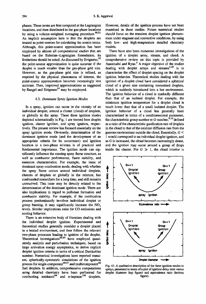
594 S.K. Aggarwal
phases. These terms are first computed at the Lagrangian locations, and then distributed to the gas-phase locations by using a volume-weighted averaging procedure. 9°'9~ An implicit assumption here is that the droplets are treated as point sources for calculating the source terms. Although, this point-source approximation has been employed by almost all computational studies that are based on the Eulerian-Lagrangian formulation, its limitations should be noted. As discussed by Sirignano, 92 the point-source approximation is quite accurate if the droplet is much smaller than the gas-phase grid size. However, as the gas-phase grid size is refined, as required by the physical phenomena of interest, the point-source approximation becomes increasingly less accurate. Then, improved approximations as suggested by Rangel and Sirignano 93 may be employed.
4.3. Dominant Spray Ignition Modes
In a spray, ignition can occur in the vicinity of an individual droplet, around a cluster (cloud) of droplets, or globally in the spray. These three ignition modes depicted schematically in Fig. 1 are termed here droplet ignition, cluster ignition, and spray ignition, respec- tively. The present review has focused essentially on the spray ignition mode. Obviously, determination of the dominant ignition mode (and the development of an appropriate criteria for its occurrence) and ignition location in a two-phase mixture is of practical and fundamental importance. The ignition mode can sig- nificantly influence the ensuing spray flame structure, as well as combustor performance, flame stability, and emission characteristics. For example, the issue of dominant spray combustion mode, dealing with whether the spray flame occurs around individual droplets, clusters of droplets or globally in the mixture, has confounded researchers for a long time, and still remains unresolved. This issue may be directly related to the determination of the dominant ignition mode. There are also implications in regard to pollutant formation and combustor stability. For example, if the combustion process predominantly involves individual droplet or group burning, it may significantly increase the NO~ levels. Similar implications exist for CO emissions and sooting behavior.
There is an extensive body of literature dealing with the individual droplet ignition. Experimental and theoretical studies generally consider a droplet placed in a heated environment, and then follow the relevant two-phase processes leading to ignition of the droplet. Theoretical investigations 94'95 have employed quasi- steady analysis and perturbation techniques, based on large activation energy asymptotics, to derive explicit droplet ignition criteria in terms of a critical Damkohler number. Numerical investigations have reported transi- ent, spherically-symmetric simulations of the ignition
96 97 98 process for single-component ' and multicomponent fuel droplets. In addition, comprehensive computations using detailed chemistry have been performed for combusting methanol 99 and n-heptane 1°° droplets.
However, details of the ignition process have not been examined in these studies. Future numerical studies should focus on the transient droplet ignition phenom- enon under stagnant and convective conditions, by using both low- and high-temperature detailed chemistry models.
There have also been numerous investigations of the ignition of a droplet array, stream, and cloud. A comprehensive review on this topic is provided by Annamalai and Ryan. 5 A major objective of the studies dealing with droplet arrays and streams 5'39 is to characterize the effect of droplet spacing on the droplet ignition behavior. Theoretical studies dealing with the ignition of a droplet cloud have considered a spherical cloud of a given size containing monosized droplets, which is suddenly introduced into a hot environment. The ignition behavior of a cloud is markedly different than that of an isolated droplet. For example, the minimum ignition temperature for a droplet cloud is much lower than that of a small isolated droplet. The ignition behavior of a cloud has generally been characterized in terms of a nondimensional parameter, the characteristic group number or G-number, 9'1° defined as a ratio of the characteristic gasification rate of droplets in the cloud to that of the oxidizer diffusion rate from the gaseous environment outside the cloud. Essentially, G < 1 would correspond to an individual droplet ignition, and as G is increased, the cloud becomes increasingly dense, and the ignition may occur around a group of drops inside the cluster. For G >> 1, the cloud interior is
J .S
s p r a y igni t ion
I I I I
E q u i v W n ~ e rotlo
\o,,1 o . 1 / D r o p l e t Group i F
spray Ignition
I , I I I
Droplet d iameter
Fig. 43. A qualitative description of the three ignition modes in sprays, presented in terms of a plot of ignition delay time versus droplet diameter (top figure) and equivalence ratio (bottom
figure).
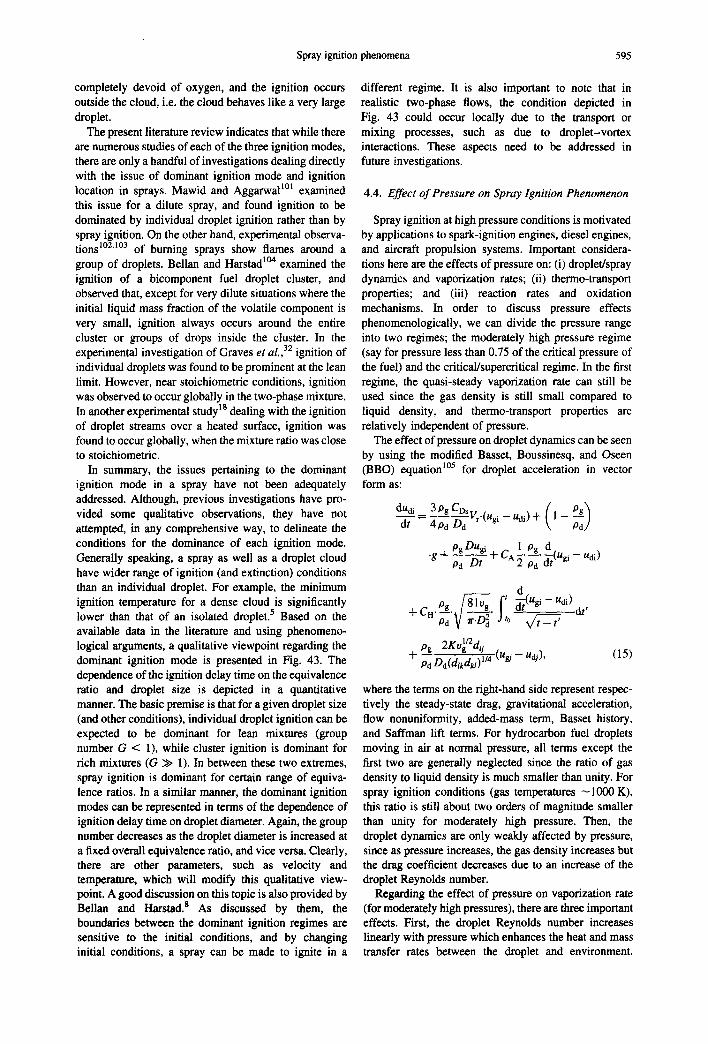
Spray ignition phenomena 595
completely devoid of oxygen, and the ignition occurs outside the cloud, i.e. the cloud behaves like a very large droplet.
The present literature review indicates that while there are numerous studies of each of the three ignition modes, there are only a handful of investigations dealing directly with the issue of dominant ignition mode and ignition location in sprays. Mawid and Aggarwal mt examined this issue for a dilute spray, and found ignition to be dominated by individual droplet ignition rather than by spray ignition. On the other hand, experimental observa- tions 1°2"m3 of burning sprays show flames around a group of droplets. Bellan and Harstad 1°4 examined the ignition of a bicomponent fuel droplet cluster, and observed that, except for very dilute situations where the initial liquid mass fraction of the volatile component is very small, ignition always occurs around the entire cluster or groups of drops inside the cluster. In the experimental investigation of Graves et a1.,32 ignition of individual droplets was found to be prominent at the lean limit. However, near stoichiometric conditions, ignition was observed to occur globally in the two-phase mixture. In another experimental study 1~ dealing with the ignition of droplet streams over a heated surface, ignition was found to occur globally, when the mixture ratio was close to stoichiometric.
In summary, the issues pertaining to the dominant ignition mode in a spray have not been adequately addressed. Although, previous investigations have pro- vided some qualitative observations, they have not attempted, in any comprehensive way, to delineate the conditions for the dominance of each ignition mode. Generally speaking, a spray as well as a droplet cloud have wider range of ignition (and extinction) conditions than an individual droplet. For example, the minimum ignition temperature for a dense cloud is significantly lower than that of an isolated droplet, s Based on the available data in the literature and using phenomeno- logical arguments, a qualitative viewpoint regarding the dominant ignition mode is presented in Fig. 43. The dependence of the ignition delay time on the equivalence ratio and droplet size is depicted in a quantitative manner. The basic premise is that for a given droplet size (and other conditions), individual droplet ignition can be expected to be dominant for lean mixtures (group number G < 1), while cluster ignition is dominant for rich mixtures (G >> 1). In between these two extremes, spray ignition is dominant for certain range of equiva- lence ratios. In a similar manner, the dominant ignition modes can be represented in terms of the dependence of ignition delay time on droplet diameter. Again, the group number decreases as the droplet diameter is increased at a fixed overall equivalence ratio, and vice versa. Clearly, there are other parameters, such as velocity and temperature, which will modify this qualitative view- point. A good discussion on this topic is also provided by Bellan and Harstad. s As discussed by them, the boundaries between the dominant ignition regimes are sensitive to the initial conditions, and by changing initial conditions, a spray can be made to ignite in a
different regime. It is also important to note that in realistic two-phase flows, the condition depicted in Fig. 43 could occur locally due to the transport or mixing processes, such as due to droplet-vortex interactions. These aspects need to be addressed in future investigations.
4.4. Effect o f Pressure on Spray Ignition Phenomenon
Spray ignition at high pressure conditions is motivated by applications to spark-ignition engines, diesel engines, and aircraft propulsion systems. Important considera- tions here are the effects of pressure on: (i) droplet/spray dynamics and vaporization rates; (ii) thermo-transport properties; and (iii) reaction rates and oxidation mechanisms. In order to discuss pressure effects phenomenologically, we can divide the pressure range into two regimes; the moderately high pressure regime (say for pressure less than 0.75 of the critical pressure of the fuel) and the critical/supereritical regime. In the first regime, the quasi-steady vaporization rate can still be used since the gas density is still small compared to liquid density, and therrno-transport properties are relatively independent of pressure.
The effect of pressure on droplet dynamics can be seen by using the modified Basset, Boussinesq, and Oseen (BBO) equation 1°5 for droplet acceleration in vector form as:
dUdi 3pgCDs dt ( P g ) ~dd = ~ d - ~ d Vr'(Ugi - Udi ) + 1 --
p.ggOu,i + 1 p~, d Q g ~ pd Dt CA ~" ~" 5 ( u ~ i - - udi)
¢ d + C pg 8/-~g ~to "~(Ugi -- Udi)..dI '
rt " p--~" v r.--~d " X /rt _ t ,
Pg 2Ku~/2dii + - - ~ d D ~ / , , (uej -- udj ), (15)
where the terms on the right-hand side represent respec- tively the steady-state drag, gravitational acceleration, flow nonuniformity, added-mass term, Basset history, and Saffman lift terms. For hydrocarbon fuel droplets moving in air at normal pressure, all terms except the first two are generally neglected since the ratio of gas density to liquid density is much smaller than unity. For spray ignition conditions (gas temperatures ~1000 K), this ratio is still about two orders of magnitude smaller than unity for moderately high pressure. Then, the droplet dynamics are only weakly affected by pressure, since as pressure increases, the gas density increases but the drag coefficient decreases due to an increase of the droplet Reynolds number.
Regarding the effect of pressure on vaporization rate (for moderately high pressures), there are three important effects. First, the droplet Reynolds number increases linearly with pressure which enhances the heat and mass transfer rates between the droplet and environment.
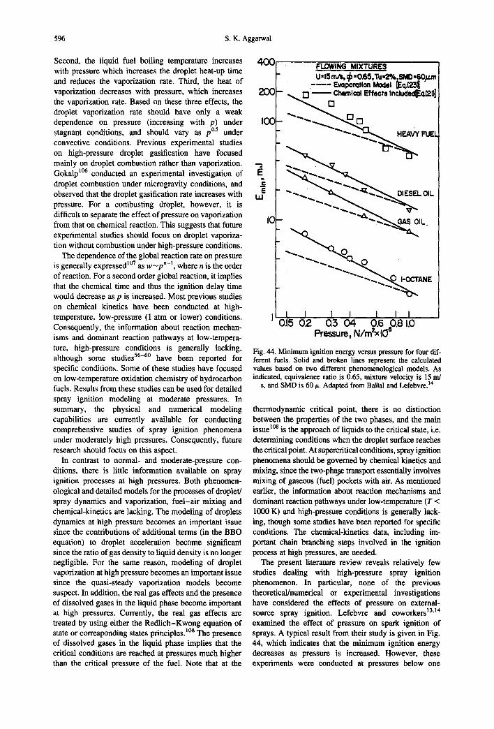
596 S.K. Aggarwal
Second, the liquid fuel boiling temperature increases with pressure which increases the droplet heat-up time and reduces the vaporization rate. Third, the heat of vaporization decreases with pressure, which increases the vaporization rate. Based on these three effects, the droplet vaporization rate should have only a weak dependence on pressure (increasing with p) under stagnant conditions, and should vary as pO.5 under convective conditions. Previous experimental studies on high-pressure droplet gasification have focused mainly on droplet combustion rather than vaporization. Gokalp 1°6 conducted an experimental investigation of droplet combustion under microgravity conditions, and observed that the droplet gasification rate increases with pressure. For a combusting droplet, however, it is difficult to separate the effect of pressure on vaporization from that on chemical reaction. This suggests that future experimental studies should focus on droplet vaporiza- tion without combustion under high-pressure conditions.
The dependence of the global reaction rate on pressure is generally expressed 1°7 as w ~ p "-I, where n is the order of reaction. For a second order global reaction, it implies that the chemical time and thus the ignition delay time would decrease as p is increased. Most previous studies on chemical kinetics have been conducted at high- temperature, low-pressure (1 atm or lower) conditions. Consequently, the information about reaction mechan- isms and dominant reaction pathways at low-tempera- ture, high-pressure conditions is generally lacking, although some studies 56-6° have been reported for specific conditions. Some of these studies have focused on low-temperature oxidation chemistry of hydrocarbon fuels. Results from these studies can be used for detailed spray ignition modeling at moderate pressures. In summary, the physical and numerical modeling capabilities are currently available for conducting comprehensive studies of spray ignition phenomena under moderately high pressures. Consequently, future research should focus on this aspect.
In contrast to normal- and moderate-pressure con- ditions, there is little information available on spray ignition processes at high pressures. Both phenomen- ological and detailed models for the processes of droplet/ spray dynamics and vaporization, fuel-air mixing and chemical-kinetics are lacking. The modeling of droplets dynamics at high pressure becomes an important issue since the contributions of additional terms (in the BBO equation) to droplet acceleration become significant since the ratio of gas density to liquid density is no longer negligible. For the same reason, modeling of droplet vaporization at high pressure becomes an important issue since the quasi-steady vaporization models become suspect. In addition, the real gas effects and the presence of dissolved gases in the liquid phase become important at high pressures. Currently, the real gas effects are treated by using either the Redlich-Kwong equation of state or corresponding states principles./°a The presence of dissolved gases in the liquid phase implies that the critical conditions are reached at pressures much higher than the critical pressure of the fuel. Note that at the
400
20(2
IOC
IC
FLOWING MIXTURES U,lSm/s, ~-0.65,Tu.,2%~SMD.EOH,,m
. . . . EvQpomtlcm Model ~q,k~l ~ D C h e m i c Q I Effects Includld~Eo,{21}]
_ ~'~'..~ ~ ~
- ~ ' ~ ' ~ . ~ HEAVY FUEL
- . _ O,ES O,,
-
- " ~ ' " ~ ~ - - ~ O i'OCTANE
I I I I 1 I I 0.15 0 2 0:3 0 4 0.6 0.810
Pressure, N / m ~ l ~
Fig. 44. Minimum ignition energy versus pressure for four dif- ferent fuels. Solid and broken lines represent the calculated values based on two different phenomenological models. As indicated, equivalence ratio is 0.65, mixture velocity is 15 m/
s, and SMD is 60/~. Adapted from Ballal and Lefebvre. 14
thermodynamic critical point, there is no distinction between the properties of the two phases, and the main issue l°s is the approach of liquids to the critical state, i.e. determining conditions when the droplet surface reaches the critical point. At supercritical conditions, spray ignition phenomena should be governed by chemical kinetics and mixing, since the two-pha)e transport essentially involves mixing of gaseous (fuel) pockets with air. As mentioned earlier, the information about reaction mechanisms and dominant reaction pathways under low-temperature (T < 1000 K) and high-pressure conditions is generally lack- ing, though some studies have been reported for specific conditions. The chemical-kinetics data, including im- portant chain branching steps involved in the ignition process at high pressures, are needed.
The present literature review reveals relatively few studies dealing with high-pressure spray ignition phenomenon. In particular, none of the previous theoretical/numerical or experimental investigations have considered the effects of pressure on external- source spray ignition. Lefebvre and coworkers 13'14 examined the effect of pressure on spark ignition of sprays. A typical result from their study is given in Fig. 44, which indicates that the minimum ignition energy decreases as pressure is increased. However, these experiments were conducted at pressures below one
Spray ignition phenomena 597
atmosphere. Experimental studies dealing with the spontaneous ignition of sprays have reported correlations to represent the effect of pressure on ignition delay. Some typical results from Ikegami et al. 63 and Kong and Reitz 77 are illustrated in Figs 28, and 42, respectively. As indicated, the ignition delay time generally decreases as the pressure is increased. Based on the ignition data reported by various experimental studies, the variation of ignition delay with pressure can be expressed as tig~ p-n with the pressure exponent varying between 0.7 and 2.0.
In summary, fundamental understanding and model- ing capabilities for high-pressure spray ignition pro- cesses are notably lacking. Experiential studies dealing with spray autoignition phenomena at high pressure have focused on the global effect of pressure by measuring ignition delay time as function of pressure and other parameters. None of the previous computational studies of external-source ignition have examined the effects of pressure on the transient two-phase processes during the ignition kernel growth, or on the global ignition behavior. This is somewhat surprising since both physical and numerical models are now available for a detailed study of spray ignition processes under moder- ately high pressures. Future computational studies should focus on this aspect. In addition, considerable effort will be needed to develop adequate models for the processes of droplet/spray vaporization, fuel-air mixing, and chemical kinetics at pressures approaching and exceeding critical values.
5. SUMMARY AND CONCLUDING REMARKS
Previous research dealing with external-source igni- tion and spontaneous ignition in liquid fuel sprays have been discussed in this review. In contrast to gaseous mixtures, a fundamental issue for two-phase mixtures pertains to the dominant ignition mode, since ignition can occur in three different ignition modes, namely the individual droplet ignition, droplet cluster ignition, and spray ignition. This review has essentially dealt with the third ignition mode. Some discussion regarding the first two ignition modes, and which mode is likely to be dominant in a given two-phase mixture, has been provided. Experimental and theoretical studies dealing with various aspects of external-source ignition in sprays have been reviewed in Section 2, while those dealing with spontaneous spray ignition have been reviewed in Section 3. Some important topics for further research have been discussed in Section 4.
A majority of experimental investigations on external- source ignition have employed spark ignition to examine the ignition characteristics of monodisperse and poly- disperse sprays, nearly-quiescent and flowing sprays, and single-component and multicomponent fuel sprays. Some experimental studies have also examined spray ignition in the thermal boundary of a heated wall. All these experimental studies have mainly focused on global spray ignition behavior, providing the dependence of the ignition energy (or ignition delay time) on spray
properties which include a suitably-defined mean droplet diameter (SMD or area mean diameter), overall equivalence ratio, fuel volatility, mixture velocity, and pressure. Theoretical investigation of external-source ignition has ranged from phenomenological models to transient, one-dimensional, two-phase numerical models with global one-step, reduced, and detailed multi-step chemistry. A variety of external ignition sources have been simulated, including spark ignition and heated wall. Important conclusions from these experimental and theoretical studies are as follows:
I. Ignitability limits for liquid fuel-air mixtures are wider (in terms of overall equivalence ratio) com- pared to those for gaseous fuel-air mixtures. These limits of course depend upon the mean droplet size for the former case.
2. Both experimental and numerical studies show the existence of an optimum droplet size and equiv- alence ratio corresponding to a minimum in the igni- tion delay time (or ignition energy). In addition, the optimum droplet size is shown to depend strongly on the equivalence ratio and fuel volatility, and weakly on other spray properties. Similarly, the optimum equivalence ratio is shown to be deter- mined by the mean droplet size and fuel volatility. These optimum values are shown to exist for a variety of spray ignition situations. More compre- hensive computations using multidimensional, two-phase models and detailed chemistry should be performed to examine this aspect further. Experimental studies should focus on more quanti- tative information using different fuels and a wider range of parameters.
3. Some experimental and numerical studies have noted the statistical nature of the spray ignition phenomenon. This implies for a given set of con- ditions or parameters, only a range of ignition delays or ignition energies and not their absolute values can be obtained. In other words, a given igni- tion delay only represents certain probability of ignition. More detailed investigations are needed to further examine this aspect of spray ignition.
4. Ignition behavior of polydisperse sprays appears to be dominated by smaller droplets. For polydisperse sprays, the issue of the dominant ignition mode becomes quite important. Additional studies deal- ing with this aspect, especially to delineate spray conditions for the probability of each mode, are needed. These studies should also focus on the probability of multiple ignition modes in a poly- disperse spray; for example, the ignition may occur around individual droplets (for larger droplets) as well as globally in the spray or near a cluster of droplets.
5. Issues regarding the dominant ignition mode are not adequately addressed. For two-phase mixtures, it is perhaps not sufficient to discuss ignitability limits without mentioning the dominant ignition mode, since ignitability limits may be different for each mode.
598 S.K. Aggarwal
6. Investigations dealing with multicomponent fuel sprays have considered the ignition of bicomponent fuel sprays, Results show that the ignition behavior of a bicomponent spray is strongly dependent on the initial liquid fuel composition and volatility differential of component fuels. Another important observation from both numerical and experimental investigations is that ignition behavior is domi- nated by the more volatile fuel. An important implication here is that the ignitability of a low- volatile fuel spray can be greatly enhanced by adding a small amount of a volatile component, whereas the ignitability of a volatile fuel spray is hardly affected by adding a significant amount of low-volatile fuel. It is important to note that the previous studies have been limited to bicomponent fuel sprays. In addition, the chemical-kinetic aspects of ignition for multicomponent fuel sprays have not been examined. Future computa- tional studies should include a detailed chemistry model for a bicomponent fuel.
7. Understanding of spray ignition processes in con- vective and high-pressure situations is lacking. In particular, the transient two-phase processes during the ignition kernel growth in a turbulent flow are not adequately understood. Here, the length and time scales associated with the flame kernel, and how they compare with the turbulent length and times scales, will be important. An interesting fun- damental configuration for experimental and com- putational studies would be the spark ignition of two-phase mixtures in a vortical structure. With regard to high-pressure spray ignition phenom- enon, reliable models for spray vaporization and chemical-kinetics at high pressures are not yet available. Experimental studies should focus on this aspect. Other potential areas for future research include the ignition of emulsified-fuel, slurry-fuel, and high-density fuel sprays. Also, the role of gravity in the spray ignition process, which is rele- vant for space applications, should be investigated.
Relatively speaking, the spontaneous ignition of liquid fuel sprays has been studied more extensively compared to the external-source ignition. Various experimental investigations dealing with the autoignition of homo- genous and heterogeneous mixtures can be broadly classified into three groups, namely autoignition in a constant-volume enclosure, autoignition by injecting a spray into a heated air stream, and autoiguition of a mixture in a shock tube. Most of these investigations have focused on the global autoignition characteristics by developing ignition delay correlations in terms of the Arrbenius plots of ignition delay time versus reciprocal of the gas temperature. These correlations provide good qualitative information about the effects of relevant parameters on the ignition delay, but limited quantitative information due to the wide scatter of data. The large variation of the experimental data can be attributed to different ignition criteria employed by various investi- gators, uncertainties associated with the specific
experimental set-up used, different amounts of vaporiza- tion or differences of fuel vapor concentrations, and flow nonuniformities. Some typical ignition delay correla- tions reported by different investigators are summarized in Tables 2-4. As noted in these tables, most exper- imental studies have concentrated on providing data on the dependence of ignition delay time on temperature and pressure. Information about the effects of spray characteristics on ignition delays is rather sketchy. Future investigations should focus on this aspect. In particular, the effects of droplet size, size distribution and fuel type should be examined in a comprehensive manner, and the role of vaporization in the autoignition process should be adequately characterized. Another important aspect not adequately investigated deals with the effects of flow inhomogeneities, transport processes, and turbulence. The role of vortex structures, that are directly related to spatial nonuniformities and turbu- lence, has also not been examined.
Theoretical investigations dealing with the spray autoignition phenomenon have employed one-dimen- sional, transient computations with global one-step and detailed multi-step chemistry models, as well as multi- dimensional, two-phase simulations with reduced mechanisms. These studies provide not only global information in terms of ignition delay correlations, but also details about the transient ignition process. Future computational studies should employ more detailed vaporization and chemistry models in order to char- acterize the effects of droplet size, fuel type and other spray parameters. A comprehensive, multidimensional numerical model may also be an excellent tool to investigate the role of flow inhomogeneities and transport processes in the autoignition process, as well as the issues related to the ignition location in autoignition situations. Finally, the issues related to the dominant ignition mode in autoignition situations should also be investigated by using such detailed numerical models.
It is important to note that the autoignition character- istics of gaseous mixtures have been studied extensively, using a variety of experimental configurations, such as well-stirred flow reactors, rapid compression machines, constant-volume vessels and shock tubes. Many of these studies have focused on obtaining or validating detailed reaction mechanisms that are directly relevant to autoignition chemistry for a wide range of temperatures. A major outcome of these studies is understanding of low-temperature chemical kinetics phenomena for different fuels, including cool flame phenomena, two- stage ignition, and negative temperature coefficient. These detailed chemicai-kinetic models should be used in future computational studies of spray autoignition phenomena. Since the dominant chain-branching steps are different for low-temperature and high-temperature conditions, the computational model may need a switching capability to employ different chemistry models depending upon the prevailing temperature.
As a final note, it should be mentioned that the present review covers only certain aspects of spray ignition

Spray ignition phenomena 599
phenomenon. General ignition phenomena have a much wider scope than what is covered in this review. There are many analytical, computational, and experimental studies dealing with the ignition of gaseous fuel-air mixtures and droplet ignition which are not included in the present review. There are also other ignition techniques that have not been discussed in this review. These include combustion-torch ignition, H2 laser- induced ignition, H3 and plasma jet ignition, TM These techniques fall in the category of external-source ignition, and have been primarily been employed for the ignition of gaseous mixtures. Another important and related topic not included in this review is the laser ignition of propellants.
Acknowledgements--The author acknowledges past funding from AFOSR, ARO, and NASA, which motivated him to work on the topic of spray ignition. His past associations with Professor W. A. Sirignano, who has been his mentor and friend, and with his own students are greatly appreciated.
1. Sato, J., Konishi, K., Okada, H. and Niioka, T., Twenty- first Symposium (International) on Combustion, pp. 695- 702 (1986),
2. Edwards, C. F., Siebers, D. L. and Hoskin, D. H., SAE paper no. 920108, 1992.
3. Yule, A. J., J. Fluid Mech., 1978, 89, 413. 4. Rah, S.-C., Sarofim, A. F. and Beer, J. M., Combust. Sci.
Technol., 1986, 48, 273-284. 5. Annamalai, K. and Ryan, W., Prog. Energy Combust. Sci.,
1992, 15, 221. 6. Laster, W. R. and Annamalai, K., Chem. Engng Commun.,
1991, 105, 201. 7. Siehel, M. and Palaniswamy, S., Twentieth Symposium
(International) on Combustion, pp. 1789-1798 (1984). 8. BeUan, J. and Harstad, K., Combust. Sci. Technol., 1987,
53, 75. 9. Chiu, H. H. and Liu, T. M., Combust. Sci. TechnoL, 1977,
17, 127. I0. Chiu, H. H. and Lin, C. L., Twenty-sixth Symposium
(International) on Combustion, pp. 1653-1661 (1996). 11. Rao, K. V. L. and Lefebvre, A. H., Combust. Flame, 1976,
27, 1. 12. Ballal, D. R, and Lefebvre, A. I-I., Proc. R. Soc. A, 1978,
364, 277, 13. Ballal, D. R. and Lefebvre, A. H., Combust. Flame, 1979,
35, 163. 14. Ballal, D. R. and Lefebvre, A. H., Eighteenth Symposium
(International) on Combustion, pp. 1737-1746 (1980). 15. Aggarwal, S. K. and Sirignano, W. A., Twentieth
Symposium (International) on Combustion, pp. 1773- 1780 (1984).
16. Westbrooke, C. K. and Dryer, F. L., Combust. Sci. TechnoL, 1981, 27, 31.
17. Aggarwal, S. K., Tong, A. and Sirignano, W. A., 22. AIAA J., 1984, ~2 (10), 1448.
18. Sommer, H.T., Twenty-firstSymposium(lnternational)on Combustion, pp. 641-646 (1986).
19. Dietrich, D. L., Danis, A. M., Namer, I. and Cernansky, N. P., A stochastic model for the ignition of a monodisperse fuel spray, Spring Technical Meeting of the Central States Section of the Combustion Institute, Dearborn, MI, May 1989.
20. Danis, A. M., Namer, I. and Cernansky, N. P., Combust. Flame, 1988, 74, 285.
21. Dietrich, D. L., Cemansky, N. P., Somasbekara, M. M., and Namer, I., Twenty-third Symposium (International) on Combustion, pp. 1383-1390 (1990).
22. Wehe, S. and Ashgriz, N., Combust. Sci. Technol,, 1992, 86, 45.
23. Sirignano, W. A., Formulation of spray combustion equations, in Numerical Modeling in Combustion, eds T. J. Chung, Chap. 9, Taylor and Francis, London, 1993.
24. Aggarwal, S. K. and Sirignano, W. A., Combust. Sci. Technol., 1985, 46, 289.
25. Gutheil, E., Combust. Flame, 1993, 93, 239. 26. Gutheil, E., Combust. Sci. Technol., 1995, 105, 265. 27. Singh, A. K. and Polymeropoulos, C. E., Twenty-first
Symposium (International) on Combustion, pp. 513-519 (1986).
28. Aggarwal, S. K., J. Propulsion Power, 1988, 4, 14. 29. Aggarwal, S. K., Combustion Flame, 1987, 69, 291. 30. Dryer, F. L. and Glassman, I., High-temperature oxidation
of CO and CH4, in Fourteenth Symposium (International) on Combustion, pp. 987-1003 (1972).
31. Miyasaka, K. and Mizutani, Y., Ignition delays of spray columns behind a reflected shock, in Sixteenth Symposium (International) on Combustion, pp. 639-645 (1976).
32. Graves, C. B., Tang, Y. L. and Skifstad, J. G., AIAA J., 1986, 24 (12), 1994.
33. Chan, K. K. and Polymeropouios, C. E., An experimental investigation of the minimum ignition energy of mono- disperse sprays, Eastern Section/Combustion Institute, Fall Technical Meeting (1981).
34. Aggarwal, S. K. and Nguyen, K., Chem. Engng Commun., 1990, 88, 23.
35. Burgoyne, J. H. and Cohen, L., Proc. R. Soc. A, 1954, 225, 375.
36. Hayashi, S., Kumagai, S. and Sakai, T., Combust. Sci. Technol., 1976, 15, 169.
37. Mizutani, Y. and Nakajima, A., Combust. Flame, 1973, 20, 343.
38. Polymeropoulos, C. E. and Das, S., Combust. Flame, 1975, 25, 247.
39. Sangiovanni, J. J. and Kestin, A. S., Sixteenth Symposium (International) on Combustion, pp. 577-592 (1976),
40. Laster, W. R. and Annamalai, K., Chem. Engng Commun., 1991, 105, 201.
41. Livengood, J. C. and Wu, P. C., Fifth Symposium (International) on Combustion, pp. 347-356 (1954).
42. Mawid, M. and Aggarwal, S. K., J. Non-Equilib. Thermodyn., 1990, 15, 369.
43. Law, C. K., Prog. Energy Combust. Sci., 1982, 8, 169. 44. Aggarwal, S. K., Int. J. HeatMass Transfer, 1987, 30, 1949. 45. Aggarwal, S. K., Combust. Flame, 1989, 76, 5. 46. Lee, K.-P., Wang, S.-H. and Wong, S.-C., Combust. Sci.
Technol., 1996, 113, 493. 47. Bergeron, C. A. and Hallett, W. L. H., Combust. Sci.
Technol., 1989, 65, 181. 48. Yukao, C.-Y., Whang, J.-J., and Wong, S.-C., Ignition of
bicomponent fuel droplets under forced condition, Corn- bust. Sci. Technol., submitted.
49. Benson, S. W., Prog. Energy Combust. Sci., 1981, 7, 125. 50. Griffiths, J. F. and Scott, S. K., Prog. Energy Combust.
Sci., 1987, 13, 161. 51. Lund, C. M., Lawrence Livermore National Laboratory
Report UCRL-52504 (1978). 52. Wamatz, J., 18th Symposium (International) on Combus-
tion, pp. 369-384 (1980). 53. Westbrook, C. K. and Dryer, F. L., Eighteenth Symposium
(International) on Combustion, pp. 749-764 (1980). 54. Westbrook, C. K., Wamatz, J. and Pit.z, W. J., Twenty-
second Symposium (International) on Combustion, pp. 893-901 (1988).
55. Curran, H. J., Dunphy, M. P., Simme, J. M., Westbrook, C. and Pitz, W. J., Twenty-fourth Symposium (International) on Combustion, pp. 769-776 (1992).
600 S.K. Aggarwal
56. Chevalier, C., Pitz, W. J., Warnatz, J., Westhrook, C. K. and Melenk, H., Twenty-fourth Symposium (International) on Combustion, pp. 92-101 (1992).
57. Carlier, M., Con'e, C., Minetti, R., Pauwels, J. F., Ribancourr M. and Sochet, L-R., Twenty-third Symposium (International) on Combustion, pp. 1753- 1758 (1990).
58. Schreiber, M., Sadat Sakak, A., Lingens, A. and Griffiths, J. F., Twenty-fifth Symposium (International) on Combus- tion, pp. 933-940 (1994).
59. Griffiths, J. F., Coppersthwalte, D. and Phillips, C. H., Westbrook, C. and pitz, W. J., Twenty-third Symposium (International) on Combustion, pp. 1745- 1752 (1990).
60. Chandraratna, M. R. and Griffiths, J. F., Combust. Flame, 1994, 99, 626.
61. Lira T.-M. and Simmons, R. F., Twenty-first Symposium (International) on Combustion, pp. 455-462 (1986).
62. Ikura, S., Kadota, T. and Hiroyasu, H., Trans. Japan Soc. Mech. Engrs, 1981, 41, 1559.
63. Ikegami, M., Miwa, K., Ohmija, T. and Nishitani, T., Trans. Japan Soc. Mech. Engrs, 1987, 53B, 274.
64. Kwon, S.d., Arai, M. and Hiroyasu, H., J. Marine Engng Soc. Japan, 1989, 24, 26.
65. Mizutani, Y., Chung, J. D. and Nakabe, K., Trans. Japan Soc. Mech. Engrs, 1990, 56B, 2802.
66. Cavaliere, A., Ciajolo, A., Danna, A., Mercogliano, R. and Ragucci, R., Combust. Flame, 1993, 93, 279.
67. Mullins, B. P., Parts 1-VIII. Fuel, 1953, 32, 211. 68. Spadaccini, L. J. and TeVelde, J. A., Combust. Flame,
1982, 46, 283. 69. Tacina, R. R., Autoignition in a premixing-prevaporizing
fuel duct using three different fuel injection systems at inlet air temperatures to 1250 K, NASA TM-82938 (1983).
70. Spadaccini, L. J. and Colket HI, M. B., Prog. Energy Combust. Sci., 1994, 20, 431.
71. Vermeer, D. J., Meyer, J. W. and Oppenheim, A. K., Combust. Flame, 1972, 18, 327.
72. Miyasaka, K. and Mizutani, Y., Combust. Flame, 1975, 25, 177.
73. Mizutanl, Y., Nakabe, K., Yoshida, M., Nogiwa, H. and Jinrong, H., Prog, Aeronaut. Astronaut., 1988, 113, 37.
74. Mizutani, Y., Nakabe, K. and Chung, J. D., Twenty-third Symposium (International) on Combustion, pp. 1455- 1460 (1990).
75. Aggarwal, S. K. and Cha, S., Combust. Sci. Technol., 1988, 59, 213.
76. Halstead, M. P., Kirseh, L. J. and Quinn, C. P., Combust. Flame, 1977, 30, 45.
77. Kong, S.-C. and Reitz, R. D., ASME J. Engng Gas Turbines Power, 1993, 115, 781.
78. Facth, G. M., Prog. Energy Combast. Sci., 1983, 9, 1. 79. Crowe, C. T., ASME J. Fluid Engng, 1982, 104, 297. 80. Sirignano, W. A., ASME J. Fluid Engng, 1992, 115, 345. 81. Reid, R. C., Prausnltz, J. M. and Sherwood, T. K., The
Properties of Gases and Liquids, 3rd Edn, McGraw-Hill, New York (1977).
82. Aggarwal, S. K., Shu, Z, Mongia, H. and Hura, H., Mnlticomponant fuel effects on the vaporization of a surrogate single-component fuel droplet, in 36th Aero- space Sciences Meeting~ Reno, Nevada (1998).
83. Stengele, J., Bauer, H.-J. and Witti8, S., Numerical study of bicomponent droplet vaporization in a high pressure environment, paper 96-GT-442, ASME/IGTI Congress, Birmingham, UK (1996).
84. Abramzon, B. and Sirignano, W. A., Int. J. Heat Mass Transfer, 1989, 32, 1605.
85. Linan, A. and Williams, F. A., Combust. Sci. Tectmol., 1996, 114, 81.
86. Bollig, M., Pitsch, H., Hewson, J. C. and Seshadri, K., Twenty-sixth Symposium (International) on Combustion, pp. 729-737 (1996).
87. Kreutz, T. G., Nishioka, M. and Law, C. K., Combust. Flame, 1994, 99, 758.
88. Fotache, C. G., Kreutz, T. G., Zhu, D. L. and Law, C. K., Combust. Sci. Technol., 1995, 109, 373.
89. Dwyer, H. A., Reacting flows with finite-volume methods, in Numerical Modeling in Combustion, ed. T. J. Chung, Chapter 4, Taylor and Francis, London, 1993.
90. Sifignano, W. A., Numerical schemes and optimization, In Numerical Modeling in Combustion, ed. T. J. Chung, Chapter 11, Taylor and Francis, London, 1993.
91. Park, T. W., Aggarwal, S. K. and Katta, V. R., Int. J. Heat Mass Transfer, 1996, 39, 741.
92. Sirignano, W. A., Point-source approximation in spray calculations, in Numerical Modeling in Combustion, ed. T. J. Chung, Chapter 12, Taylor and Francis, London, 1993.
93. Rangel, R. H. and Sirignano, W. A., Part A. Numer. Heat Transfer, 1989, 16, 37.
94. Law, C. K., Combustion Flame, 1975, 26, 89. 95. Mawid, M. and Aggarwal, S. K., Combust. Sci. Technol.,
1989, 65, 137. 96. Huang, L.-W. and Chen, C.-H., Combust. Flame, 1995,
109, 145. 97. Shaygan, N. and Prakash, S., Combust. Flame, 1995, 102, 1. 98. Aggarwal, S. K. and Mawid, M., Combustion Flame,
1991, 84, 197. 99. Marchese, A. J., Dryer, F. L., Colantonio, R. O. and
Nayagam, V., Twenty-sixth Symposium (International) on Combustion, pp. 1209-1217 (1996).
100. Marchese, A. J., Dryer, F. L., Nayagam, V. and Colantonio, R. O., Twenty-sixth Symposium (Inter- national) on Combustion, pp. 1219-1226 (1996).
101. Mawid, M. and Aggarwal, S. K., Combust. Flame, 1990, 81, 59.
102. McDonell, V. G., Adachi, M. and Samuelsen, G. S., Combust. Sci. Technol., 1992, 82, 225.
103. Mizutani, Y., Nakabe, K., Fuchihata, M., Akamatsu, F., Zaizen, M. and EI-Emam, S. H., Atomization Sprays, 1993, 3, 125.
104. Bellan, J. and Harstad, K., Combust. Sci. Technol., 1995, 110-111, 531.
105. Peng, F. and Aggarwal, S. K., ASME J. Engng Gas Turbines Power, 1995, 117, 453.
106. Gokalp, A., Twenty-sixth Symposium (International) on Combustion, pp. 1259-1265 (1996).
107. Williams, F. A., Combustion Theory, 2nd Edn, Benjamin/ Cummins, 1985.
108. Faeth, G. M., 26th Symposium (International) on Com- bustion, pp. 1593-1612 (1996).
109. Fuzimoto, H., Shimada, T. and Sato, G. T., Trans. Japan Soc. Mech. Engrs, 1979, 22, 1818.
110. Mullaney, G. J., lndust. Engng Chem., 1956, 51, 779. 111. Onuma, Y., Murata, N. and Shibata, K., Trans. Japan Soc.
Mech. Engrs, 1985, 51B, 4327. 112. MCattolica~ R. J., Twenty-first Symposium (International)
on Combustion, pp. 1551-1559 (1986). 113. Maas, U., Raffel, B., Wolfrum, J. and Warnatz, J.,
Observation and simulation of laser induced ignition processes in 02-03 and H2-O2 mixtures, Twenty-first Symposium (International) on Combustion, 1869-1876 (1986).
114. Carleton, F. B., Cheriyaan, G. K., Klein, N. and Weinberg, F. J., Twenty-first Symposium (International) on Combus- tion, pp. 1885-1890 (1986).


![GOVERNING COLLABORATIVE ACTIVITY: INTERDEPENDENCE …faculty.insead.edu/vikas-aggarwal/documents/[2] Aggarwal, Siggelko… · VIKAS A. AGGARWAL,1* NICOLAJ SIGGELKOW, 2and HARBIR SINGH](https://img.pdfslide.net/doc/110x75/5f086c957e708231d421f158/governing-collaborative-activity-interdependence-2-aggarwal-siggelko-vikas.jpg)