Embed Size (px)
Citation preview
Systems Engineering and Integration for Advanced Life Support System and HST
Final ReportNASA Faculty Fellowship Program - 2004
Johnson Space Center
Prepared by: Ali K. Kamrani, Ph.D.
Academic Rank: Associate Professor
University & Department University of HoustonIndustrial EngineeringHouston, TX 77204
NASA/JSC
Directorate: Engineering
Division: Crew & Thermal Systems
Branch: N/A
JSC Colleague: Donald L. Henninger, Ph.D.
Date Submitted: August 31, 2004
Contract Number: NAG 9-1526&NNJ04JF93A
12-1
ABSTRACT
Systems engineering (SE) discipline has revolutionized the way engineers and managersthink about solving issues related to design of complex systems: With continueddevelopment of state-of-the-art technologies, systems are becoming more complex andtherefore, a systematic approach is essential to control and manage their integrated designand development. This complexity is driven from integration issues. In this case, sub-systems must interact with one another in order to achieve integration objectives, and alsoachieve the overall system's required performance. Systems engineering processaddresses these issues at multiple levels. It is a technology and management processdedicated to controlling all aspects of system life cycle to assure integration at all levels.
The Advanced Integration Matrix (AIM) project serves as the systems engineering andintegration function for the Human Support Technology (HST) program. AIM providesmeans for integrated test facilities and personnel for performance trade studies, analyses,integrated models, test results, and validated requirements of the integration of HST. Thegoal of AIM is to address systems-level integration issues for exploration missions. It willuse an incremental systems integration approach to yield technologies, baselines forfurther development, and possible breakthrough concepts in the areas of technologicaland organizational interfaces, total information flow, system wide controls, technicalsynergism, mission operations protocols and procedures, and human-machine interfaces.
This report provides the summary of results based on the proposed SOW during the 2004fellowship at NASA's Johnson Space center for NFFP. These tasks were:
1. Benchmarking and the evaluation of systems engineering processes in order toidentify best practices and lesson learned.
2. Propose a SE process template for the identification of functional requirementsand its decomposition for human life support systems.
12-2
INTRODUCTION - ADVANCED INTEGRATION MATRIX (AIM)
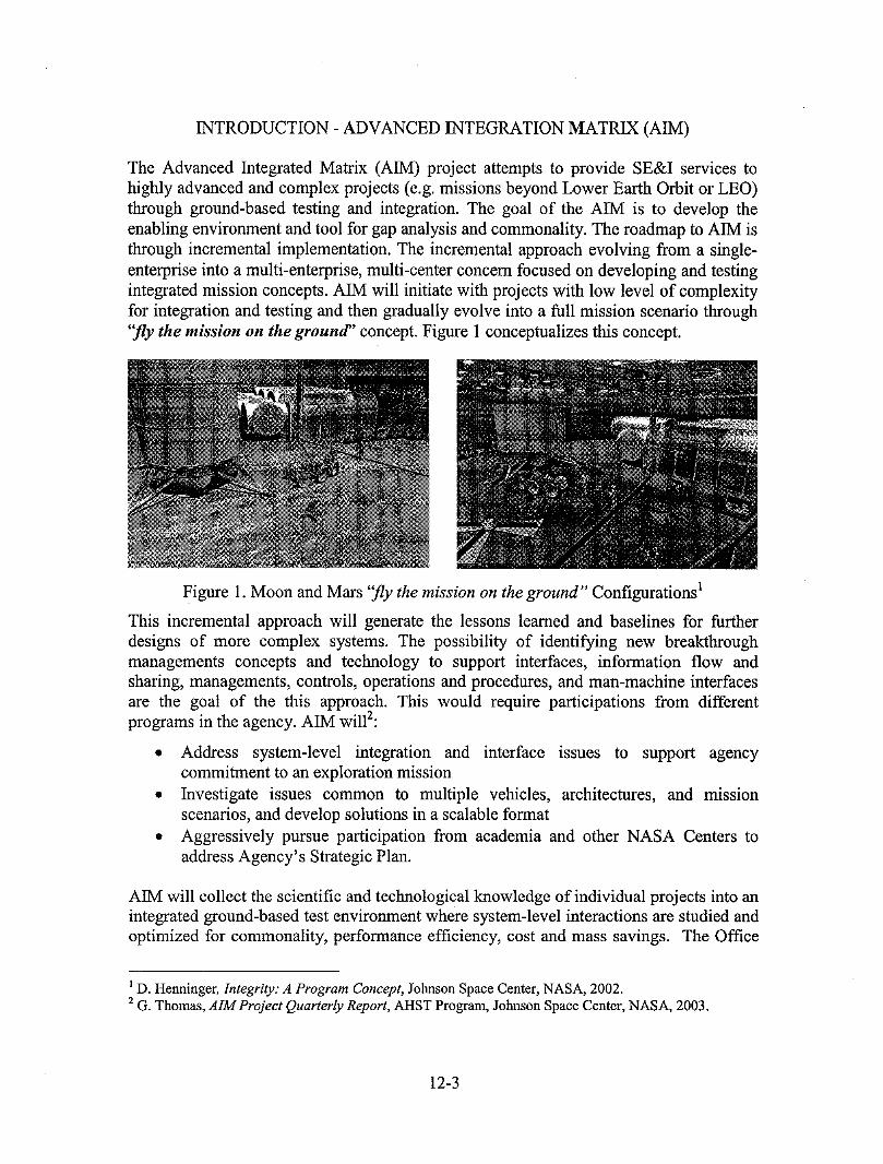
The Advanced Integrated Matrix (AIM) project attempts to provide SE&I services tohighly advanced and complex projects (e.g. missions beyond Lower Earth Orbit or LEO)through ground-based testing and integration. The goal of the AIM is to develop theenabling environment and tool for gap analysis and commonality. The roadmap to A1M isthrough incremental implementation. The incremental approach evolving from a single-enterprise into a multi-enterprise, multi-center concern focused on developing and testingintegrated mission concepts. AIM will initiate with projects with low level of complexityfor integration and testing and then gradually evolve into a full mission scenario through"fly the mission on the ground" concept. Figure 1 conceptualizes this concept.
Figure 1. Moon and Mars "fly the mission on the ground" Configurations 1
This incremental approach will generate the lessons learned and baselines for furtherdesigns of more complex systems. The possibility of identifying new breakthroughmanagements concepts and technology to support interfaces, information flow andsharing, managements, controls, operations and procedures, and man-machine interfacesare the goat of the this approach. This would require participations from differentprograms in the agency. AIM will2:
• Address system-level integration and interface issues to support agencycommitment to an exploration mission
• Investigate issues common to multiple vehicles, architectures, and missionscenarios, and develop solutions in a scalable format
• Aggressively pursue participation from academia and other NASA Centers toaddress Agency's Strategic Plan.
AIM will collect the scientific and technological knowledge of individual projects into anintegrated ground-based test environment where system-level interactions are studied andoptimized for commonality, performance efficiency, cost and mass savings. The Office
l D. Henninger, Integrity: A Program Concept, Johnson Space Center, NASA, 2002.2 G. Thomas, AIM Project Quarterly Report, AHST Progrmrt, Johnson Space Center, NASA, 2003.
12-3
of Biological and Physical Research (OBPR) has authorized initiation of the formulationphase. The purpose is to identify and solve system-level integration issues for explorationmissions beyond Low Earth Orbit through design and development of a ground-basedfacility for developing an integrated system for joint human-robotic missions.
PART I - SYSTEMS ENGINEERING PROCESS AND GENERIC MODELS
Past experience has shown that lack of planning and clear identification of objectives hasbeen the major problem associated with the design and development of any complexsystem. This approach has resulted in a system's lack of performance and finally designfailure. Traditionally, systems have been developed based on "Deliver now and FixLater. 3,, This process has suffered from lack of clear planning which resulted in failureand high cost of design modifications. In this scenario, requirements at the systems levelwere kept general in order to reduce complexity to allow for new technology integration.This has routinely evolved into last minute modifications that impacted the schedule andcost. Decisions made at the early stages of development life cycle will significantlyimpact the overall life-cycle including cost and system's effectiveness. Therefore, there isa need for a disciplined approach for integrated design and the development of newsystems. In this case, all aspects of the development are considered early in the processand used for continuous improvement. Systems Engineering is "The effective applicationof scientific and engineering efforts to 1) transform an operational need into a definedsystem configuration through the top-down iterative process of requirement analysis,functional analysis and allocation, synthesis, design optimization, test, evaluation andvalidation, 2) integrate related technical parameters and ensure the compatibility of allphysical functional and program interfaces in a manner that optimizes the totaldefinition and design, and 3) integrate reliability, maintainability, usability, safety,serviceability, disposability to meet cost, schedule, and technical performance
objectives 4. Systems engineering is also considered a process for Mana[ging Technology.System engineering process has evolved in seven different paradigmsL A summary ofthese processes are discussed below.
1. Build-Test-Fix: This method consists of three basic steps, fabricate a design, testthe system, and then operate. This method is typically used for in-house softwaredevelopment where the customer is also the developer. It is considered to be a simplebut effective approach. Although, it lacks the requirements analysis phase that makesit not suitable for any complex systems design.
2. Staircase: The Staircase method allows for better management and control of systemdevelopment. This method is considered to be a systematic flow through the SEprocess. It is well suited for the developments of existing systems variants. In this
3 Benjamin S. Blanchard, Systems Engineering Management, Wiely Interscience, 1998.4 Systems Engineering Fundamentals, Defense Acquisition University Press, 2001.5 Norman B. Reilly, Successful Systems Engineering for Engineers and Managers, Kluwer AcademicPublishers, 1993.
12-4
case, already developed requirements are modified. The export version of a militaryaircraft is an example this concept. Requirements-Specification-Design-Fabrication-Testing-Acceptance-Operate area steps in the staircase SE cycle.
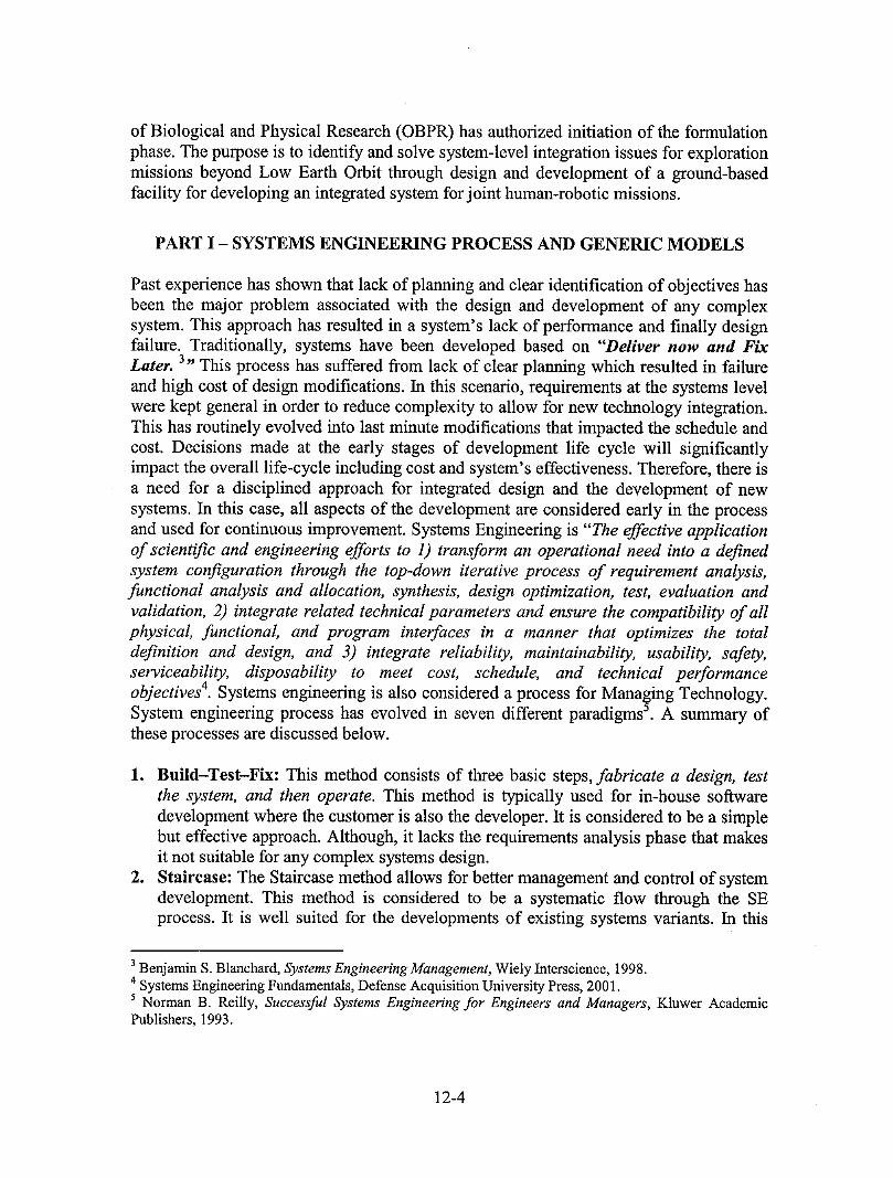
3. Waterfall: This method improves the staircase method by adding feedback loopsbetween successive stages as shown in Figure 2. Through these feedbacks, each stageis capable of gaining knowledge from the subsequent stages. The success of thismodel is dependant on understanding and processing revisions through feedbackanalysis.
I SystemRequirements
Requirements
PreliminaryDesign
_ Detailed _Design
_ Codeand _Debug
_ Testand _Pre-operatlons
_ Operations and ]Maintenance
Figure 2. Waterfall Systems Engineering Process Model
4. Early Prototype: The early prototype process is an extension to the staircase withfeed back cycle. This method is used when it is difficult for customer to identifyrequirements, but could recognize them through some model or prototyperepresentation. The advantage of this method is due to direct interaction betweenstakeholders. Some of the difficulties with this approach are 1) the initial prototypecould discourage the customer 2) it suggests an unattainable goals and 3) prototypedesign becomes the main objective rather than the actual customer's need.
5. Spiral: The Spiral method, as shown in Figure 3 is an extension to the early prototypeconcept. The primary advantage of the spiral method is the detailed development ofrequirements, specifications, and designs. The significant challenge for the spiralmethod is managing the prototype transitions. Some of the advantages are:• Risk-driven sequential phases with user involvement.• Considers highest risks issue first (Requirements understanding, Technical
feasibility and System operations).• Cycles of risk-driven phases, spiral around and end with a final waterfall wrap.
6. Rapid Development: The success of this process dependent on fast-paced innovation(RSDFTAO-- RSDFTAO...) while completing multiple small starts to the finalsystem, This process requires cross-functional teams with the ability to work acrossthe functional boundaries.
12-5

Figure 3. Systems Engineering Spiral model 6
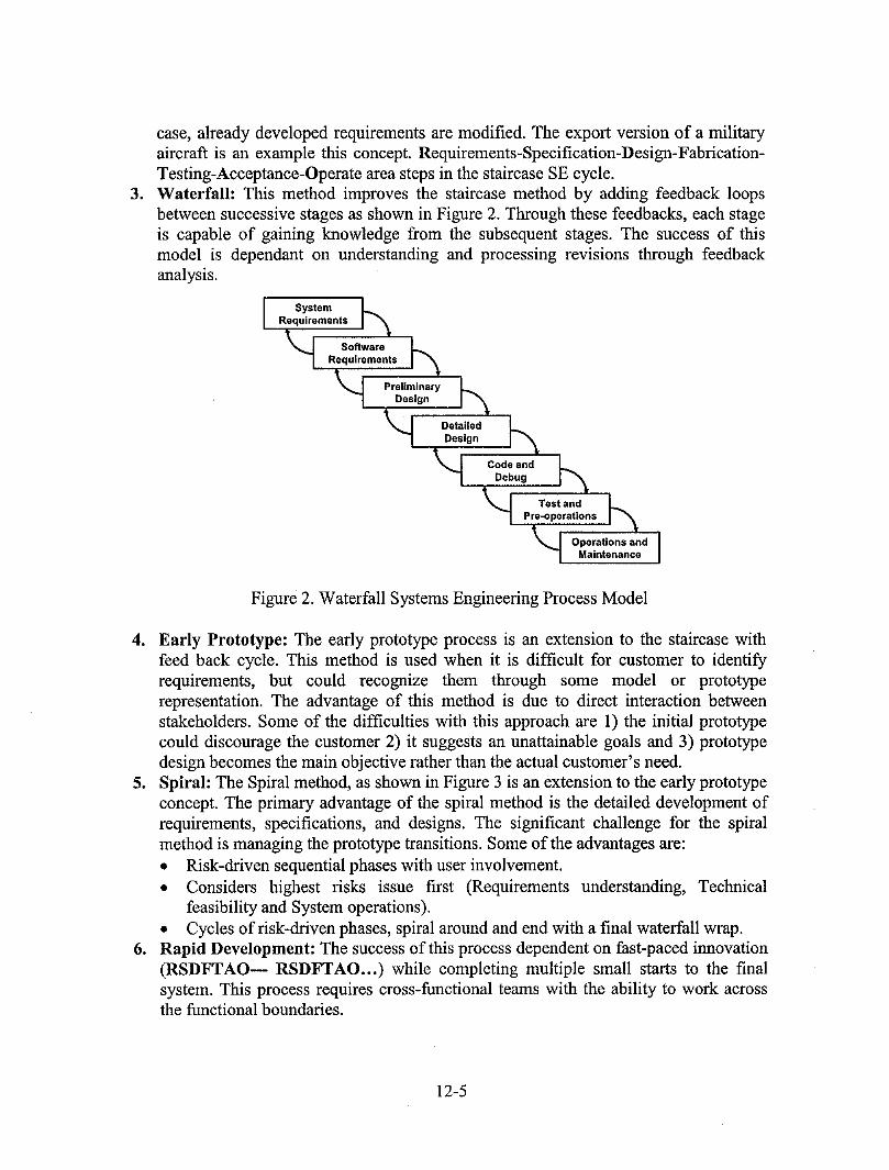
7. Integrated: Integrated or concurrent development method consists of cross-functional teams with members from all of the functional areas working closelytogether, sharing details of their portion of the design as it progresses, and developingall aspects of the system simultaneously. The result is overlapping and managing theoverall life cycle. Concurrent Engineering (CE) is defined as the systematic andintegrated approach to systems life cycle design. CE is also known as the Design forLife Cycle model. Concurrent engineering is the implementation of parallel designsby cross-functional teams including suppliers. Without empowered team membersand the free flow of communications, this method will not function. Figure 4illustrates an overview of the integrated SE infrastructure. Tablel lists partialcomparison among these models.
A model that is typically used to define the critical elements of SE process is the SystemsEngineering Capability Maturity Model (SE-CMM) 7. These elements consist of activitieswhich define 'what' has to be done. Table 2 lists these tasks. Tasks for design anddevelopment are listed in engineering group, project elements provide the managementinfrastructure and finally the organization elements provide the business infrastructure tosupport systems engineering effort.
6 B. W. Boehm,SpiralModelof SoftwareDevelopment,TutorialSoftwareProjectManagementeditedbyR. H. ThayerandM. Dorfman,IEEEPress, 1988.7SystemsEngineeringCapabilityMaturityModelTM, Version1.1,SoftwareEngineeringInstitute,CarnegieMellonUniversity,1995.
12-6
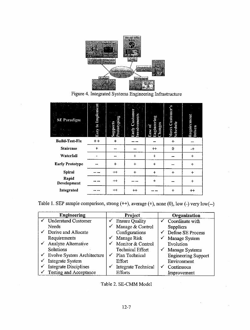
Figure 4. Integrated Systems Engineering Infrastructure
Build-Test-Fix + + + .... + --
Staircase + - -- ++ 0 -+
Waterfall -- + + -- +
Early Prototype -- + + + -- +
Spiral .... ++ + + + +
Rapid .... ++ .... + .. +Development
Integrated .... ++ ++ .... + 4-+
Table 1. SEP sample comparison, strong (++), average (+), none (0), low (-) very low(--)
Engineering Project Organization¢" Understand Customer ¢" Ensure Quality ¢" Coordinate with
Needs ,/ Manage & Control Suppliers¢" Derive and Allocate Configurations ,/ Define SE Process
Requirements ¢" Manage Risk ¢" Manage System,/ Analyze Alternative ¢" Monitor & Control Evolution
Solutions Technical Effort ¢" Manage Systems¢" Evolve System Architecture ¢" Plan Technical Engineering Support,/ Integrate System Effort Environment,/" Integrate Disciplines ¢" Integrate Technical ,/ Continuous¢" Testing and Acceptance Efforts Improvement
Table 2. SE-CMM Model
12-7
SYSTEMS ENGINEERING SAMPLE PROCESS MODLES
"Vee" Process is widely used by many industries (Figure 5).
A] r, r,+VDR PDR p_
ed_c Evolutionary
Figure 5. "Vee" Process as applied to NASA Projects 8
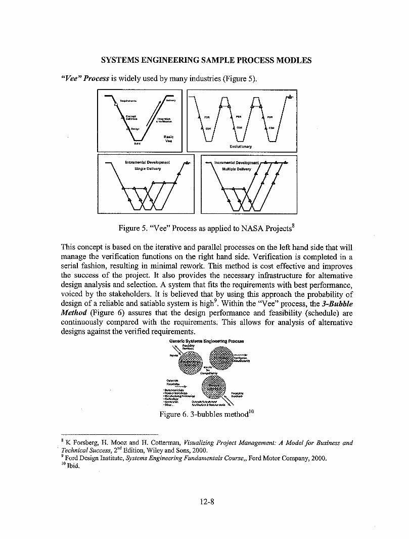
This concept is based on the iterative and parallel processes on the left hand side that willmanage the verification functions on the right hand side. Verification is completed in aserial fashion, resulting in minimal rework. This method is cost effective and improvesthe success of the project. It also provides the necessary infrastructure for alternativedesign analysis and selection. A system that fits the requirements with best performance,voiced by the stakeholders. It is believed that by using this approach the probability ofdesign of a reliable and satiable system is high 9. Within the 'Wee" process, the 3-BubbleMethod (Figure 6) assures that the design performance and feasibility (schedule) arecontinuously compared with the requirements. This allows for analysis of alternativedesigns against the verified requirements.
¢a_l_:S_rd_m_ Ent_lr_ Pmc_
- @Figure 6.3-bubbles method TM
8 K Forsberg, H. Mooz and H. Cotterman, Visualizing Project Management: A Model for Business andTechnical Success, 2"dEdition, Wiley and Sons, 2000.9Ford Design Institute, Systems Engineering Fundamentals Course,, Ford Motor Company, 2000.l0Ibid.
12-8
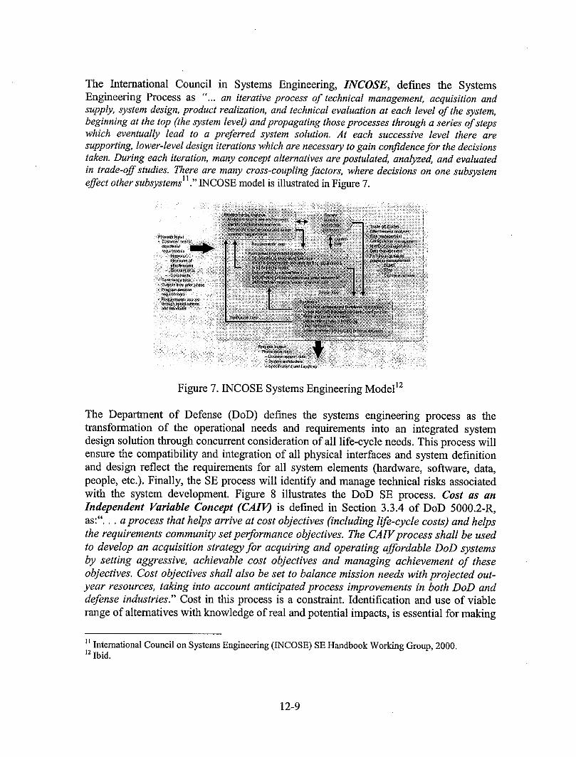
The International Council in Systems Engineering, INCOSE, defines the SystemsEngineering Process as "'... an iterative process of technical management, acquisition andsupply, system design, product realization, and technical evaluation at each level of the system,beginning at the top (the system level) and propagating those processes through a series of stepswhich eventually lead to a preferred system solution. At each successive level there aresupporting, lower-level design iterations which are necessary to gain confidence for the decisionstaken. During each iteration, many concept alternatives arepostulated, analyzed, and evaluatedin trade-off studies. There are many cross-coupling factors, where decisions on one subsystem
11 ,, ....effect other subsystems . INCOSE model is illustrated in Figure 7.
Figure 7. INCOSE Systems Engineering Model lz
The Department of Defense (DoD) defines the systems engineering process as thetransformation of the operational needs and requirements into an integrated systemdesign solution through concurrent consideration of all life-cycle needs. This process willensure the compatibility and integration of all physical interfaces and system definitionand design reflect the requirements for all system elements (hardware, software, data,people, etc.). Finally, the SE process will identify and manage technical risks associatedwith the system development• Figure 8 illustrates the DoD SE process• Cost as anIndependent Variable Concept (CAIIO is defined in Section 3.3.4 of DoD 5000.2-R,as:".., a process that helps arrive at cost objectives (including life-cycle costs) and helpsthe requirements community set performanee objectives. The CAIV process shall be usedto develop an acquisition strategy for acquiring and operating affordable DoD systemsby setting aggressive, achievable cost objectives and managing achievement of theseobjectives• Cost objectives shall also be set to balance mission needs with projected out-year resources, taking into account anticipated process improvements in both DoD anddefense industries." Cost in this process is a constraint. Identification and use of viablerange of alternatives With knowledge of real and potential impacts, is essential for making
II InternationalCouncilon SystemsEngineering(INCOSE)SEHandbookWorkingGroup,2000.lzIbid.
12-9
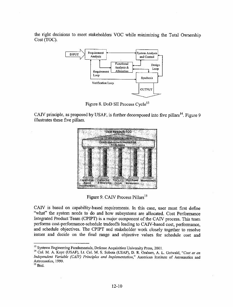
the right decisions to meet stakeholders VOC while minimizing the Total OwnershipCost (TOC).
IN [ Requirement /t LSystem Analysis L
[INPU-------_TV" [ Analysis ] andControl ]" [
['--_ Functi°nal I"--'-_Analysis& _ Design[Loop[
Requirement Allocation
Loop _-JSynthesis
Verification Loop
Figure 8. DoD SE Process Cycle 13
CAW principle, as proposed by USAF, is further decomposed into five pillars 14.Figure 9illustrates these five pillars.
})?;:
, }iii# )) } )i
t ........
Figure 9. CAW Process Pillars 15
CAW is based on capability-based requirements. In this case, user must first define"what" the system needs to do and how subsystems are allocated. Cost PerformanceIntegrated Product Team (CPIPT) is a major component of the CAW process. This teamperforms cost-performance-schedule tradeoffs leading to CAW-based cost, performance,and schedule objectives. The CPIPT and stakeholder work closely together to resolveissues and decide on the final range and objective values for schedule cost and
t3Systems Engineering Fundamentals, Defense Acquisition University Press, 2001.t4 Col. M. A. Kaye (USAF), Lt. Col. M. S. Sobota (USAF), D. R. Graham, A. L. Gotwald, "Cost as anIndependent Variable (CAIV) Principles and Implementation," American Institute of Aeronautics andAstronautics, 1999.15Ibid.
12-10
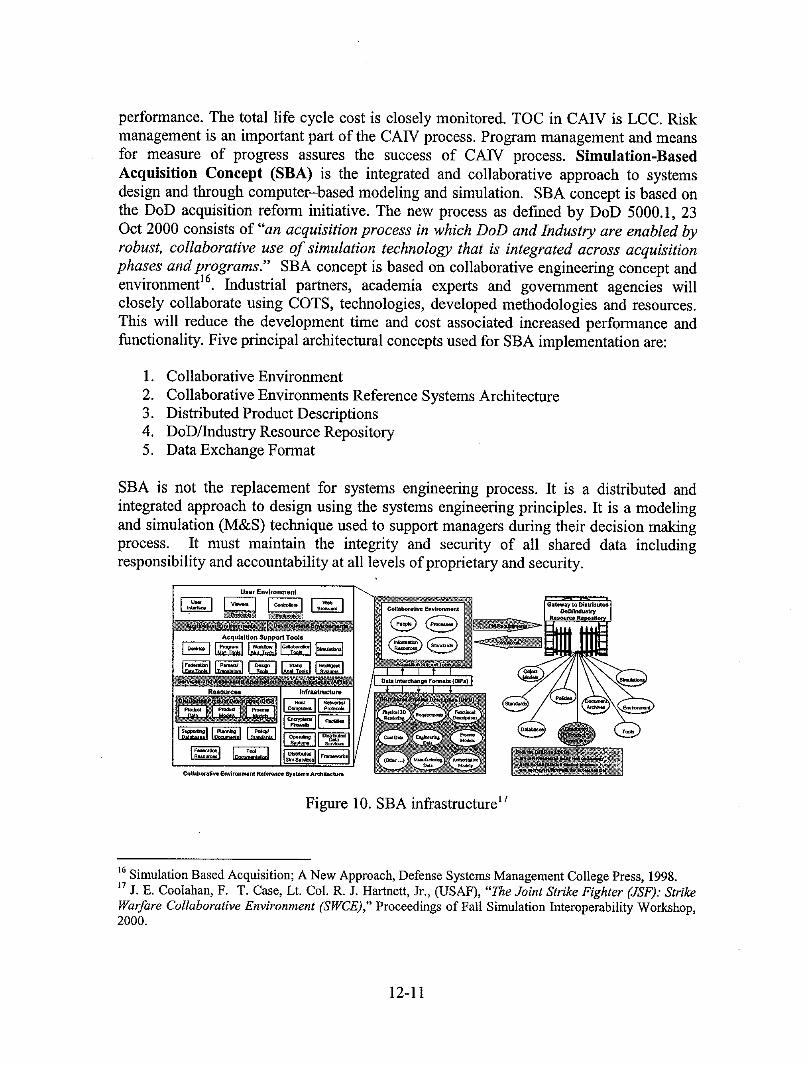
performance. The total life cycle cost is closely monitored. TOC in CAIV is LCC. Riskmanagement is an important part of the CAIV process. Program management and meansfor measure of progress assures the success of CAIV process. Simulation-BasedAcquisition Concept (SBA) is the integrated and collaborative approach to systemsdesign and through computer-based modeling and simulation. SBA concept is based onthe DoD acquisition reform initiative. The new process as defined by DoD 5000.1, 23Oct 2000 consists of "an acquisition process in which DoD and Industry are enabled byrobust, collaborative use of simulation technology that is integrated across acquisitionphases and programs." SBA concept is based on collaborative engineering concept andenvironment 16. Industrial partners, academia experts and government agencies willclosely collaborate using COTS, technologies, developed methodologies and resources.This will reduce the development time and cost associated increased performance andfunctionality. Five principal architectural concepts used for SBA implementation are:
1. Collaborative Environment
2. Collaborative Environments Reference Systems Architecture3. Distributed Product Descriptions4. DoD/Industry Resource Repository5. Data Exchange Format
SBA is not the replacement for systems engineering process. It is a distributed andintegrated approach to design using the systems engineering principles. It is a modelingand simulation (M&S) technique used to support managers during their decision makingprocess. It must maintain the integrity and security of all shared data includingresponsibility and accountability at all levels of proprietary and security.
User Environment
t6Simulation Based Acquisition; A New Approach, Defense Systems Management College Press, 1998.17j. E. Coolahan, F. T. Case, Lt. Col. R. J. Hartnett, Jr., (USAF), "The Joint Strike Fighter (JSF): StrikeWarfare Collaborative Environment (SWCE)," Proceedings of Fall Simulation Interoperability Workshop,2000.
12-11
THE JOINT STRIKE FIGHTER PROGRAM
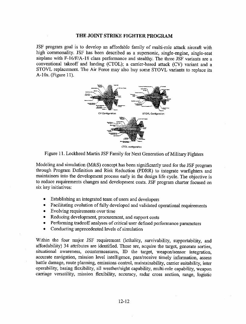
JSF program goal is to develop an affordable family of multi-role attack aircraft withhigh commonality. JSF has been described as a supersonic, single-engine, single-seatairplane with F-16/F/A-18 class performance and stealthy. The three JSF variants are aconventional takeoff and landing (CTOL); a cartier-based attack (CV) variant and aSTOVL replacement. The Air Force may also buy some STOVL variants to replace itsA-10s. (Figure 11).
2:.. :';
CV Configuration STOVL Configuration
CTOL configurafion
Figure 11. Lockheed Martin JSF Family for Next Generation of Military Fighters
Modeling and simulation (M&S) concept has been significantly used for the JSF programthrough Program Definition and Risk Reduction (PDRR) to integrate warfighters andmaintainers into the development process early in the design life cycle. The objective isto reduce requirements changes and development costs. JSF program charter focused onsix key initiatives:
• Establishing an integrated team of users and developers• Facilitating evolution of fully developed and validated operational requirements• Evolving requirements over time
• Reducing development, procurement, and support costs• Performing tradeoff analyses of critical user defined performance parameters• Conducting unprecedented levels of simulation
Within the four major JSF requirement (lethality, survivability, supportability, andaffordability) 34 attributes are identified. These are, acquire the target, generate sorties,situational awareness, countermeasures, ID the target, weapon/sensor integration,accurate navigation, mission level intelligence, pass/receive timely information, assessbattle damage, route planning, emissions control, maintainability, carrier suitability, interoperability, basing flexibility, all weather/night capability, multi-role capability, weaponcarriage versatility, mission flexibility, accuracy, radar cross section, range, logistic
12-12
footprint, payload, infrared signature, speed, maneuverability, electro-optical signature,redundancy, hardening, acoustic signature, reliability, and ferry range. The JSF attributesare the combination of functions, operational flexibility, operational constraints, andparameters. Simulation modeling and virtual prototyping has allowed the Joint StrikeFighter (JSF) concept demonstration for assembly to be accomplished with fifty percentreduction in staffing and time compared to actual planned levels iS. "For JSFdevelopments, simulations have improved the mechanical tolerances where the originallyprojected shim stock weight of 40 lbs per aircraft, as in the F-16, was reduced to lessthan 1 pound.19 ,, Cost was considered to be a major criteria during JSF requirementanalysis phase. It was used as criteria for trade-studies. JSF is developed based on thesimulation and acquisition program concept and collaborative engineering. Simulationwas extensively used during the requirements development process, and will be usedthroughout the program. Virtual prototyping and collaborative engineering was used tointegrate all stakeholders into the systems engineering process. Analysis provides theincremental approach for complete system definition, design and integration.
PART II: ALS Functional Analysis and Decompositions within AIM
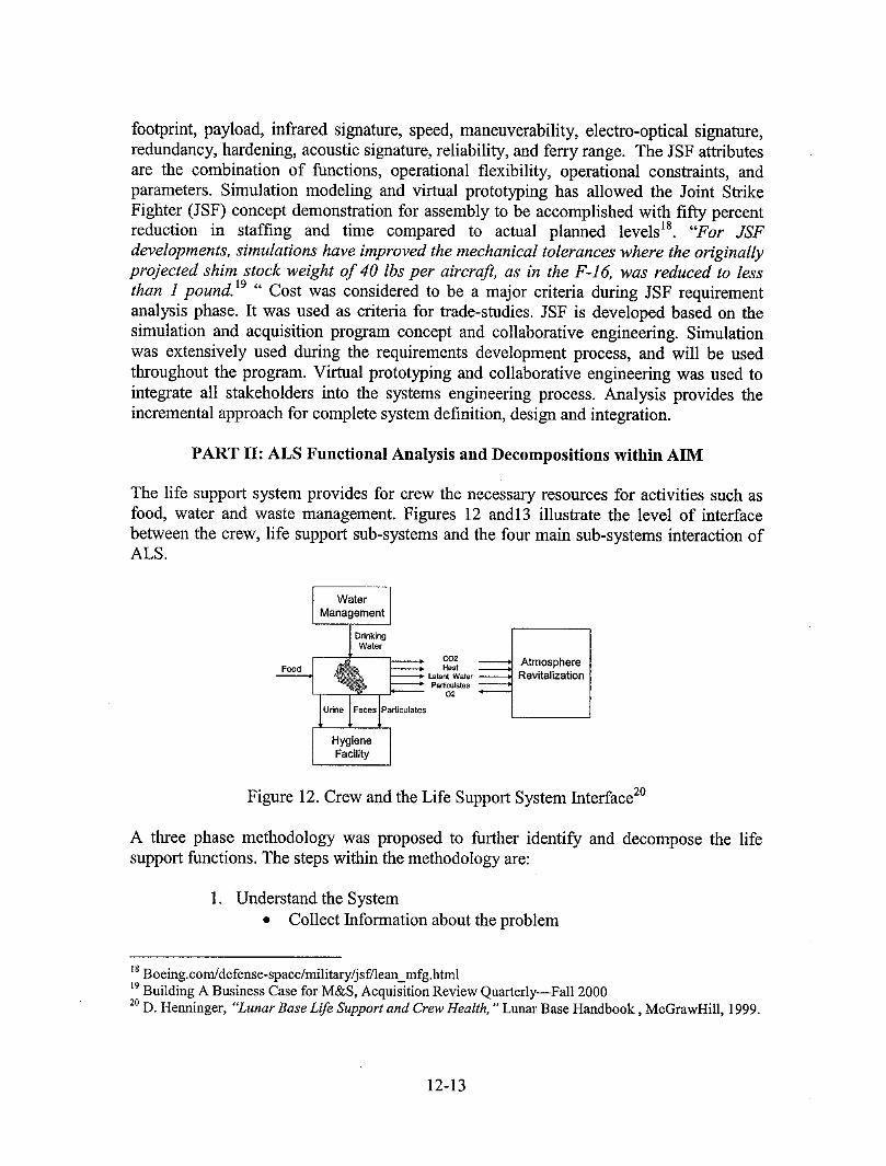
The life support system provides for crew the necessary resources for activities such asfood, water and waste management. Figures 12 andl3 illustrate the level of interfacebetween the crew, life support sub-systems and the four main sub-systems interaction ofALS.
WaterManagement
DrinkingWater
co2 AtmosphereFood Heat Revitalization
PadiculatesO2
HygieneFacility
Figure 12. Crew and the Life Support System Interface 2°
A three phase methodology was proposed to further identify and decompose the lifesupport functions. The steps within the methodology are:
1. Understand the System• Collect Information about the problem
ig Boeing.com/de fense-space/military/js f/lean_mfg.html_9Building A Business Case for M&S, Acquisition Review Quarterly--Fall 2000
20D. Henninger, "'Lunar Base Life Support and Crew Health, ""Lunar Base Handbook, McGrawHill, 1999.
12-13
• Organize the Requirements• Develop the Theme
2. Define Function
• Select requirement for functional analysis• Define Functions• Define function criteria
3. Decompose and Systematize Functions• Identify main functions• Relate functions• Check functions series• Establish criteria
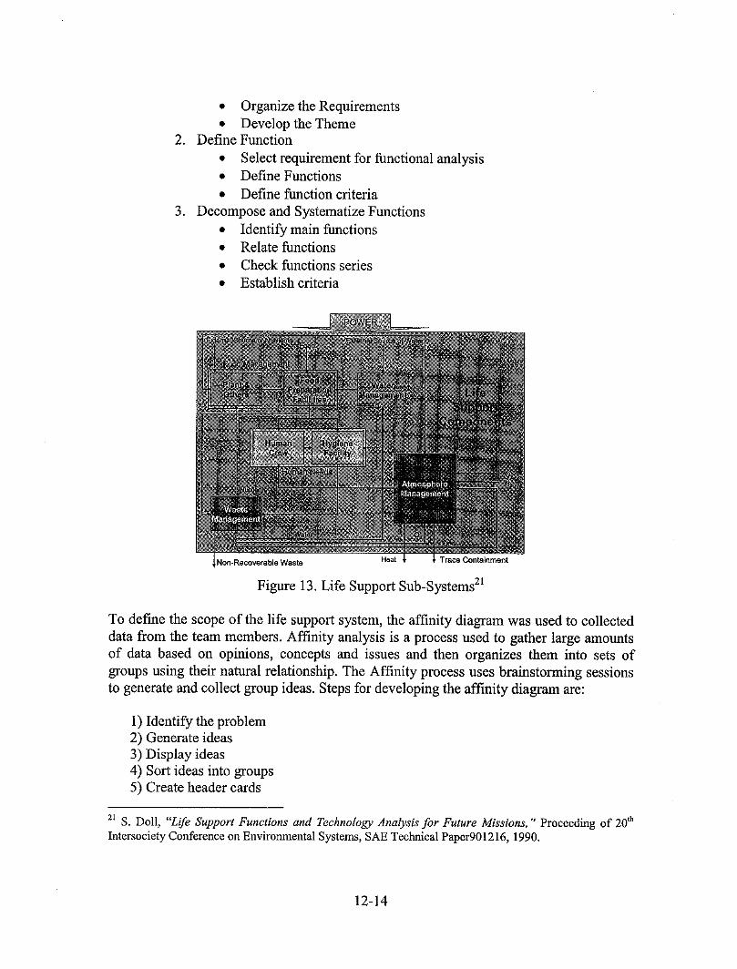
,Non-Recoverable Waste Heat Trace Containment
Figure 13. Life Support Sub-Systems 21
To define the scope of the life support system, the affinity diagram was used to collecteddata from the team members. Affinity analysis is a process used to gather large amountsof data based on opinions, concepts and issues and then organizes them into sets ofgroups using their natural relationship. The Affinity process uses brainstorming sessionsto generate and collect group ideas. Steps for developing the affinity diagram are:
1) Identify the problem2) Generate ideas3) Display ideas4) Sort ideas into groups5) Create header cards
zl S. Doll, "'LifeSupportFunctionsand TechnologyAnalysisfor FutureMissions,"'Proceedingof 20thIntersocietyConferenceon EnvironmentalSystems,SAETechnicalPaper901216,1990.
12-14
6) Draw clustered groups and finished diagram
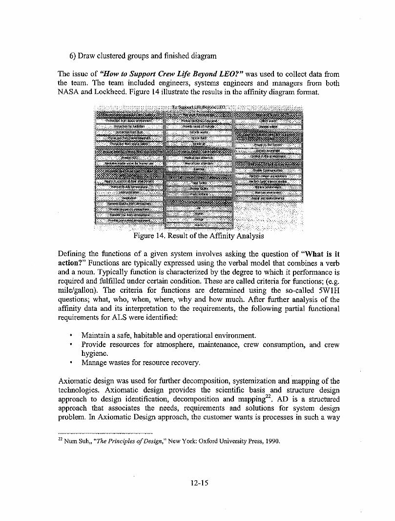
The issue of "How to Support Crew Life Beyond LEO?" was used to collect data fromthe team. The team included engineers, systems engineers and managers from bothNASA and Lockheed. Figure 14 illustrate the results in the affinity diagram format.
Figure 14. Result of the Affinity Analysis
Defining the functions of a given system involves asking the question of "What is itaction?" Functions are typically expressed using the verbal model that combines a verband a noun. Typically function is characterized by the degree to which it performance isrequired and fulfilled under certain condition. These are called criteria for functions; (e.g.mile/gallon). The criteria for functions are determined using the so-called 5WIHquestions; what, who, when, where, why and how much. After further analysis of theaffinity data and its interpretation to the requirements, the following partial functionalrequirements for ALS were identified:
, Maintain a safe, habitable and operational environment., Provide resources for atmosphere, maintenance, crew consumption, and crew
hygiene.. Manage wastes for resource recovery.
Axiomatic design was used for further decomposition, systemization and mapping of thetechnologies. Axiomatic design provides the scientific basis and structure designapproach to design identification, decomposition and mapping 22. AD is a structuredapproach that associates the needs, requirements and solutions for system designproblem. In Axiomatic Design approach, the customer wants is processes in such a way
22Num Suh,, "The Principles of Design," New York: Oxford University Press, 1990.
12-15
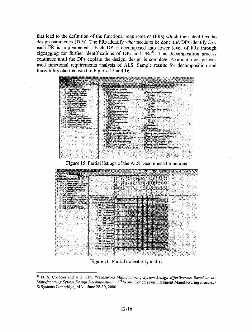
that lead to the definition of the functional requirements (FRs) which then identifies thedesign parameters (DPs). The FRs identify what needs to be done and DPs identify howeach FR is implemented. Each DP is decomposed into lower level of FRs throughzigzagging for further identifications of DPs and FRs23. This decomposition processcontinues tmtil the DPs explain the design; design is complete. Axiomatic design wasused functional requirements analysis of ALS. Sample results for decomposition andtraceability chart is listed in Figures 15 and 16.
Figure 15. Partial listings of the ALS Decomposed functions
Figure 16. Partial traceability matrix
z3 D. S. Cochran and A.K. Chu, "Measuring Manufacturing System Design Effectiveness Based on theManufacturing System Design Decomposition", 3rdWorld Congress on Intelligent Manufacturing Processes& Systems Cambridge, MA- June 28-30, 2000
12-16
CONCLUSION AND FUTURE PLANS
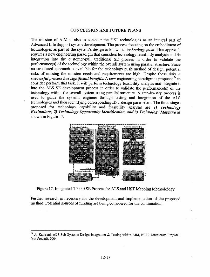
The mission of AIM is also to consider the HST technologies as an integral part ofAdvanced Life Support system development. The process focusing on the embodiment oftechnologies as part of the system's design is known as technology-push. This approachrequires a new engineering paradigm that considers technology feasibility analysis and itsintegration into the customer-pull traditional SE process in order to validate theperformance(s) of the technology within the overall system using parallel structure. Sinceno structured approach is available for the technology push method of design, potentialrisks of missing the mission needs and requirements are high. Despite these risks asuccessfulprocess has significant benefits. A new engineering paradigm is proposed 24toconsider perform this task. It will perform technology feasibility analysis and integrate itinto the ALS SE development process in order to validate the performance(s) of thetechnology within the overall system using parallel structure. A step-by-step process isused to guide the systems engineer through testing and integration of the ALStechnologies and then identifying corresponding HST design parameters. The three stagesproposed for technology capability and feasibility analysis are 1) TechnologyEvaluations, 2) Technology Opportunity Identification, and 3) Technology Mapping asshown in Figure 17.
Figure 17. Integrated TP and SE Process for ALS and HST Mapping Methodology
Further research is necessary for the development and implementation of the proposedmethod. Potential sources of funding are being considered for the continuation.
24A. Kamrani,ALSSub-SystemsDesignIntegration& TestingwithinAIM,NFFP DirectorateProposal,(not funded),2004.
12-17