Embed Size (px)
Citation preview
1
S-NPP VIIRS Instrument Performance and
Inter-Calibrations
X. Xiong and J. ButlerNASA Goddard Space Flight Center, Greenbelt, MD 20771
A. Wu, J. McIntire, Z. Wang, and N. LeiScience Systems and Applications Inc., Lanham, MD 20760
CLARREO SDT Meeting, National Institute of Aerospace, Hampton, VA (Nov 29 - Dec 01, 2016)

Outline
• S-NPP VIIRS Reflective Solar Calibration
• On-orbit Performance– SD Degradation– Spectral Bands Responses and Noise Characterization– Recent Changes and Improvements
• Inter-calibrations– Aqua MODIS and S-NPP VIIRS– Inter-calibrations with CLARREO Pathfinder Instrument
• Summary
2

3
VIIRS Reflective Solar Calibration Strategies and Activities
Rotating Telescope Assembly (RTA)
SD calibration each orbit with a fixed screen
Solar Diffuser Stability Monitor
Extended SV Port
15 RSB: M1-M11, I1-I3, DNBH/L gains: M1-5 and M7l: 0.4-2.3 mm
Daily operation => 3 per week (8 min => 5 min)
Roll maneuvers: 8-9 yearly
Solar Diffuser
4
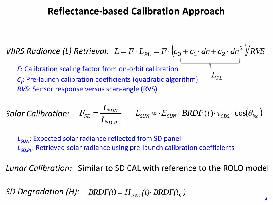
RVSdncdnccFLFL PL2
210 VIIRS Radiance (L) Retrieval:
PLSD
SUNSD
L
LF
,
Solar Calibration:
F: Calibration scaling factor from on-orbit calibration
ci: Pre-launch calibration coefficients (quadratic algorithm)
RVS: Sensor response versus scan-angle (RVS)
LSUN: Expected solar radiance reflected from SD panelLSD,PL: Retrieved solar radiance using pre-launch calibration coefficients
Reflectance-based Calibration Approach
incSDSSUNSUN tBRDFEL cos)(
)BRDF(t(t)HBRDF(t) Norm 0SD Degradation (H):
Lunar Calibration: Similar to SD CAL with reference to the ROLO model
PLL

5
SCAN
scansam
PLMOON
ROLO
PLMOON
ROLOMOON
NL
I
I
IF
/g,det,
B,, VIIRS Lunar Calibration:
IROLO: Lunar irradiance (integrated) provided by ROLO modelIMOON,PL: Lunar irradiance retrieved using pre-launch calibration coefficientsNSCAN, B, g: number of scans, pixel solid angle, aggregation factor
Lunar Calibration Methodologies
Lunar images (I1) from lunar calibration events in 2014

On-orbit Performance
6
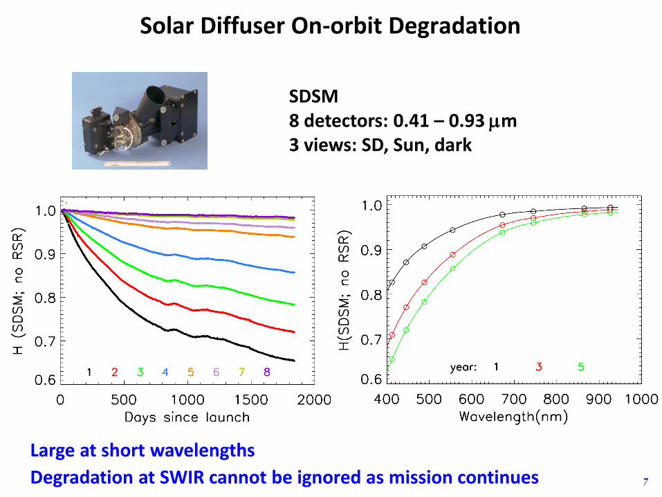
• SD Degradation– Large degradation at short wavelengths
– Small but not negligible degradation at SWIR wavelengths
– Different approach for SD degradation at SWIR as SDSM only covers wavelengths from 0.41 to 0.93 mm
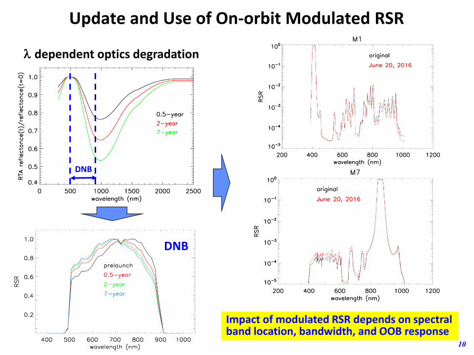
• Spectral Bands Responses – Large at NIR and SWIR region
– Strong wavelength-dependent optics degradation => modulated RSR
• Noise Characterization– Correlated with changes in spectral band responses
– Sufficient margin remains to meet specified requirements
• Recent Changes and Improvements
7
Solar Diffuser On-orbit Degradation
Large at short wavelengths
Degradation at SWIR cannot be ignored as mission continues
SDSM8 detectors: 0.41 – 0.93 mm3 views: SD, Sun, dark

Spectral Bands Responses (SD)
8
M1 0.41
M2 0.45
M3 0.49
M4 0.56
I1 0.64
M5 0.67
M6 0.75
I2 0.87
M7 0.87
M8 1.24
M9 1.38
I3 1.61
M10 1.61
M11 2.25
M7 I2

Spectral Bands Responses (SD and Lunar CAL)
9
M1 0.41
M2 0.45
M3 0.49
M4 0.56
I1 0.64
M5 0.67
M6 0.75
I2 0.87
M7 0.87
M8 1.24
M9 1.38
I3 1.61
M10 1.61
M11 2.25
Lines: SDSymbols: Moon
10
Update and Use of On-orbit Modulated RSR
l dependent optics degradation
Impact of modulated RSR depends on spectral band location, bandwidth, and OOB response
DNB
DNB

11
Detector Noise Characterization
(SNR/SNRSPEC > 1) or (NEdT/NEdTSPEC < 1): better performance
SNR for RSB NEdT for TEB
Noticeable SNR decrease in NIR/SWIR is due to degradation of sensor optical throughput

Recent Changes and Improvements
12
• Improved SDSM and SD screen vignetting function– Used data from yaw maneuvers and selected regular SD/SDSM
calibration events
• Improved normalization of SD degradation
– Revised extrapolation from first SDSM calibration to the mission beginning
• Use of lunar observations to track SD degradation
– Eliminated SD degradation difference between SDSM view and RTA view
– Derived SD degradation at SWIR wavelengths
• Added features in NASA SIPS VIIRS L1B
• Consistently reprocessed calibration LUTs
Xiong et al, “Evaluation and Improvements of SNPP VIIRS SDR,” NOAA Workshop on Life-Cycle Data Reprocessing to Advance Weather and Climate Applications, May 17-18, 2016
backup slides

13
Inter-Calibrations
Xiong et al, SPIE 2016
Methodologies for Calibration Inter-comparisons and Reference Transfer

14
Inter-Calibrations
Total drift: 0.26% Total drift: 0.02%
0.65 mm 0.86 mm
Calibration Inter-comparison of Aqua MODIS and S-NPP VIIRS Using SNO
Calibration Inter-comparison of Aqua MODIS and S-NPP VIIRS Using PICS
MODIS L1B Collection 6; VIRIS L1B from NASA Land SIPS

15
Difference (%) = (VIIRS – MODIS)*100/MODIS (no RSR correction)Differences remain after RSR correction (some getting smaller and some larger; scene dependent)
V/M Band
SNO [1]
SNO [2]
Dome C[1]
Dome C[3,4]
Desert [1]
Desert [3-5]
Desert[6]
DCC [7]
Ocean [8]
Ocean [2]
M1/B8 -0.2±1.2 0.8±0.8 -1.3±1.0 -0.2±0.7 0.1±0.9 1.6±0.3 -1.0±0.8 -0.5±1.0 -2.0±1.5 1.2±0.5
M2/B9 -0.7±1.0 -1.7±0.6 -0.5±0.7 -0.3±0.8 0.4±0.3 -1.2±0.8 -0.5±0.8 -4.0±2.0 -1.8±0.5
M3/B10 -1.0±0.7 -1.3±0.4 0.2±0.9 -0.2±0.8 1.3±0.4 -1.0±0.8 -3.5±2.0 -0.1±0.6
M4/B4 1.5±0.7 -1.5±0.3 1.8±1.5 1.6±1.0 -0.9±1.0 -0.2±0.4 -1.5±0.5 2.0±1.0 -1.5±1.5 -0.2±0.9
M5/B1 6.5±1.9 10.0±0.6 5.7±1.8 4.8±0.9 9.2±0.8 9.5±0.5 9.0±0.5 9.0±0.7 1.5±0.5
M7/B2 2.5±0.6 4.0±0.5 2.2±1.7 2.8±1.4 3.9±0.7 4.0±0.5 3.5±0.5 2.5±0.5 4.0±2.0
I1/B1 -0.3±0.7 -0.4±1.5 -1.7±0.9 -2.0±0.5
I2/B2 2.6±0.6 2.3±1.8 4.0±0.7 3.5±0.5
Published NPP VIIRS (earlier versions) and Aqua MODIS Reflectance Differences (%)

16
References
1. Wu, A., X. Xiong, C. Cao, and K. Chiang, “Assessment of SNPP VIIRS VIS/NIR radiometric calibration stability using Aqua MODIS and invariant surface targets”, IEEE Transactions on Geoscience and Remote Sensing, Vol. 54, No. 5, pp. 2918-2924, 2016.
2. Uprety, S., C. Cao, X. Xiong, S. Blonski, A. Wu, and X. Shao, “Radiometric Intercomparison between Suomi-NPP VIIRS and Aqua MODIS Reflective Solar Bands Using Simultaneous Nadir Overpass in the Low Latitudes”, J. Atmos. Oceanic Technol., 30, 2720–2736. 2013.
3. Uprety, S., C. Cao, S, Blonski, W. Wang, Assessment of VIIRS radiometric performance using vicarious calibration sites, Proc. SPIE 9218, Earth Observing Systems XIX, 92180I, doi:10.1117/12.2061855, 2014
4. Uprety, S., C. Cao, Suomi NPP VIIRS reflective solar band on-orbit radiometric stability and accuracy assessment using desert and Antarctica Dome C sites, Remote Sensing of Environment, Vol. 166, pp. 106–115, 2015, doi:10.1016/j.rse.2015.05.021.
5. Uprety, S., C. Cao, S, Blonski,, Retrospective analysis of Suomi NPP VIIRS radiometric bias for reflective solar bands due to operational calibration changes, International J. Remote Sens., 37 (22), pp.5472-5489, 2016.
6. Chang, T., X. Xiong, A. Angal, A. Wu, BRDF characterization and calibration inter-comparison between Terra MODIS, Aqua MODIS, and S-NPP VIIRS, Proc. SPIE 10000, Sensors, Systems, and Next-Generation Satellites XX, 100000Z, doi:10.1117/12.2239888, 2016.
7. Wang, W., and C. Cao, “Assessing the VIIRS RSB calibration stability using deep convective clouds”, Proc. SPIE, 9264, Earth Observing Missions and Sensors: Development, Implementation, and Characterization III, doi:10.1117/12.2068434, 2014.
8. Pahlevan, N., Z. Lee, R. Arnone, and A. Lawson, Investigating the Consistency between VIIRS and MODIS over the Oceans: The Sensor/Environmental Data Records (SDR/EDR), 2013.

17
with RSR correction
-4
-2
0
2
4
6
M1 M2 M4 M7 I1 I2
Re
fl(V
) / R
ef
(M)
(%)
After RSR correction
SNOLibya-4DomeC
NASA VIIRS L1B (before latest reprocessing)
NASA VIIRS L1B (current version)
Averaged S-NPP VIIRS and Aqua MODIS Reflectance Differences (%)
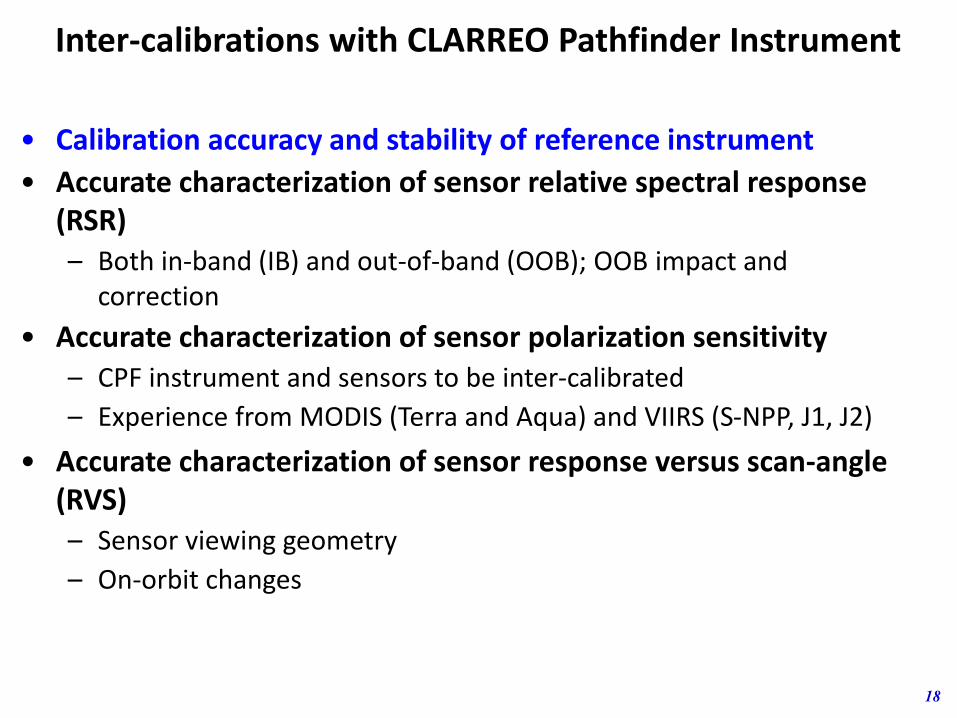
Inter-calibrations with CLARREO Pathfinder Instrument
18
• Calibration accuracy and stability of reference instrument
• Accurate characterization of sensor relative spectral response (RSR) – Both in-band (IB) and out-of-band (OOB); OOB impact and
correction
• Accurate characterization of sensor polarization sensitivity– CPF instrument and sensors to be inter-calibrated
– Experience from MODIS (Terra and Aqua) and VIIRS (S-NPP, J1, J2)
• Accurate characterization of sensor response versus scan-angle (RVS) – Sensor viewing geometry
– On-orbit changes

Inter-calibrations with CLARREO Pathfinder Instrument
19
• Solar spectral irradiance used by individual sensors
• Reflectance versus radiance-based calibration/inter-calibrations
• Sensor spatial resolutions
• Ground target BRDF and atmospheric effect
• Improved (use of) lunar model (see presentation by T. Stone)– ROLO data Reanalysis Effort
– NIST measurements with high accuracy and traceability
– Use of CNES POLO data
– GSICS activities

Summary
20
• S-NPP VIIRS continues to operate normally with overall performance meeting the need for operational users (SDRs/EDRs from IDPS) and science community (reprocessed SDRs/EDRs)
– Parallel effort by NASA VCST and NOAA SDR team
– Consistent data reprocessing
• Approaches derived from sensor calibration inter-comparisons can be adopted for CPF inter-calibration
• Considerations and effort need to be made to reduce or minimize the uncertainties of CPF inter-calibration
– Reference instrument stability, traceability, and accuracy
– Sensor performance characteristics (RSR, RVS, POL, …)
– Spatial sampling, atmospheric effect and BRDF correction
Aqua MODIS S-NPP VIIRS JPSS-1 VIIRS JPSS-2 VIIRS2002 2011 2017 2021

21
VIIRS and MODIS Spectral Bands
VIIRS Band Spectral Range (um) Nadir HSR (m) MODIS Band(s) Range HSR
DNB 0.500 - 0.900
M1 0.402 - 0.422 750 8 0.405 - 0.420 1000
M2 0.436 - 0.454 750 9 0.438 - 0.448 1000
M3 0.478 - 0.498 750 3 100.459 - 0.479
0.483 - 0.493
500
1000
M4 0.545 - 0.565 750 4 or 120.545 - 0.565
0.546 - 0.556
500
1000
I1 0.600 - 0.680 375 1 0.620 - 0.670 250
M5 0.662 - 0.682 750 13 or 140.662 - 0.672
0.673 - 0.683
1000
1000
M6 0.739 - 0.754 750 15 0.743 - 0.753 1000
I2 0.846 - 0.885 375 2 0.841 - 0.876 250
M7 0.846 - 0.885 75016 or 2
0.862 - 0.877
0.841 - 0.876
1000
250
M8 1.230 - 1.250 750 5 SAME 500
M9 1.371 - 1.386 750 26 1.360 - 1.390 1000
I3 1.580 - 1.640 375 6 1.628 - 1.652 500
M10 1.580 - 1.640 750 6 1.628 - 1.652 500
M11 2.225 - 2.275 750 7 2.105 - 2.155 500
I4 3.550 - 3.930 375 20 3.660 - 3.840 1000
M12 3.660 - 3.840 750 20 SAME 1000
M13 3.973 - 4.128 750 21 or 22 3.929 - 3.989
3.929 - 3.989
1000
1000
M14 8.400 - 8.700 750 29 SAME 1000
M15 10.263 - 11.263 750 31 10.780 - 11.280 1000
I5 10.500 - 12.400 375 31 or 3210.780 - 11.280
11.770 - 12.270
1000
1000
M16 11.538 - 12.488 750 32 11.770 - 12.270 1000
VIIRS MODIS Substitute
1 DNB
14 RSB(0.4-2.3 mm)
7 TEB
Dual Gain Bands:
M1-M5, M7, M13
16
Mo
de
rate
(ra
dio
met
ric)
ban
ds,
5 Im
agin
g b
and
s, 1
DN
B
22
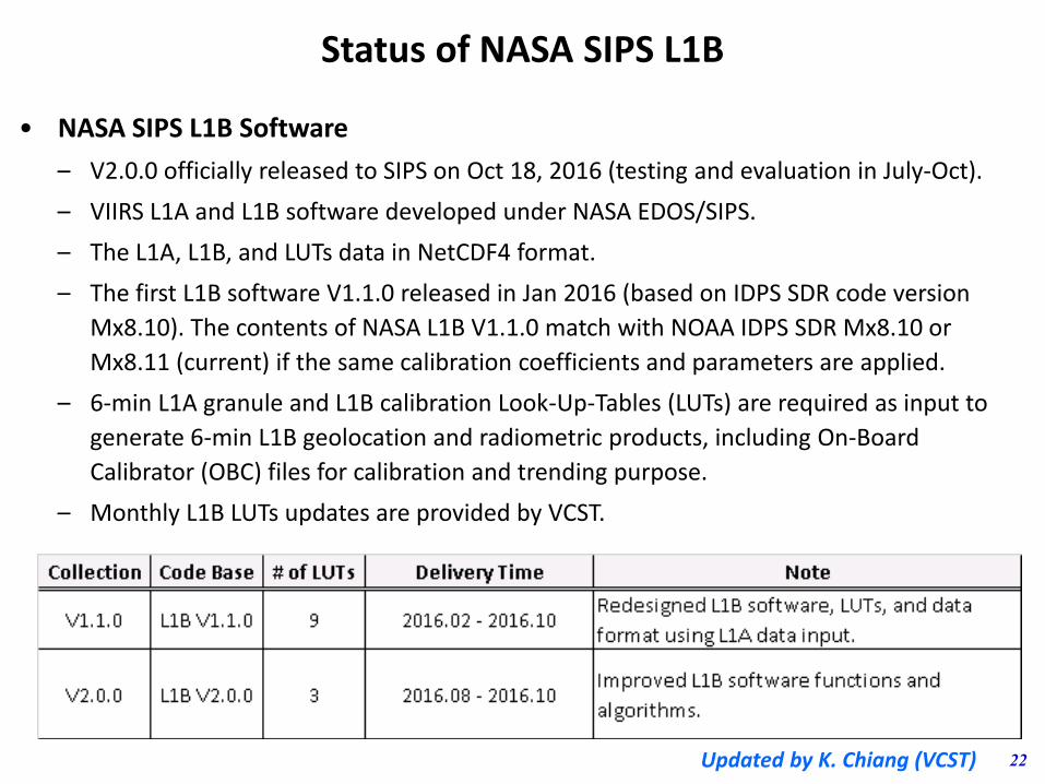
• NASA SIPS L1B Software
– V2.0.0 officially released to SIPS on Oct 18, 2016 (testing and evaluation in July-Oct).
– VIIRS L1A and L1B software developed under NASA EDOS/SIPS.
– The L1A, L1B, and LUTs data in NetCDF4 format.
– The first L1B software V1.1.0 released in Jan 2016 (based on IDPS SDR code version
Mx8.10). The contents of NASA L1B V1.1.0 match with NOAA IDPS SDR Mx8.10 or
Mx8.11 (current) if the same calibration coefficients and parameters are applied.
– 6-min L1A granule and L1B calibration Look-Up-Tables (LUTs) are required as input to
generate 6-min L1B geolocation and radiometric products, including On-Board
Calibrator (OBC) files for calibration and trending purpose.
– Monthly L1B LUTs updates are provided by VCST.
Status of NASA SIPS L1B
Updated by K. Chiang (VCST)
23
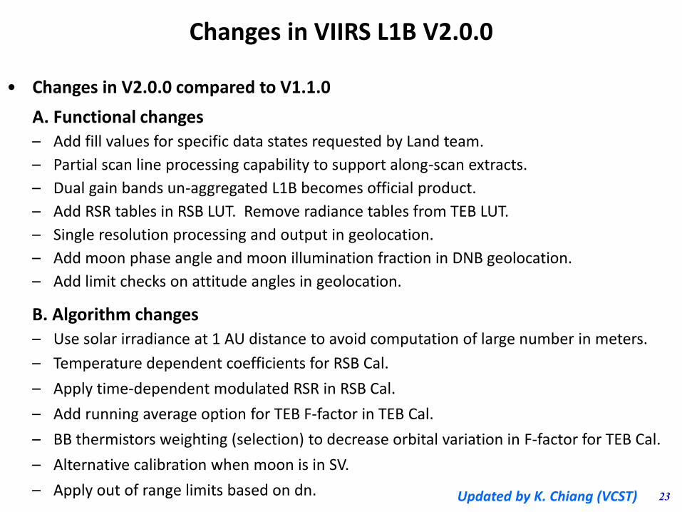
Changes in VIIRS L1B V2.0.0
• Changes in V2.0.0 compared to V1.1.0
A. Functional changes
– Add fill values for specific data states requested by Land team.
– Partial scan line processing capability to support along-scan extracts.
– Dual gain bands un-aggregated L1B becomes official product.
– Add RSR tables in RSB LUT. Remove radiance tables from TEB LUT.
– Single resolution processing and output in geolocation.
– Add moon phase angle and moon illumination fraction in DNB geolocation.
– Add limit checks on attitude angles in geolocation.
B. Algorithm changes
– Use solar irradiance at 1 AU distance to avoid computation of large number in meters.
– Temperature dependent coefficients for RSB Cal.
– Apply time-dependent modulated RSR in RSB Cal.
– Add running average option for TEB F-factor in TEB Cal.
– BB thermistors weighting (selection) to decrease orbital variation in F-factor for TEB Cal.
– Alternative calibration when moon is in SV.
– Apply out of range limits based on dn. Updated by K. Chiang (VCST)