Embed Size (px)
Citation preview

Product specifications in this catalog are subject to change without notice.Request our product specifications before purchase and/or use. Please use our products based on the information contained in this catalog and product specifications.
Part numbering system
Our part numbering system is common to all of Nippon Chemi-Con's subsidiaries worldwide, and has been switching the conventional part numbering system. The part number uses 18-digit codes to express information of principal product specifications such as product category, series name, rated voltage, capacitance, case size and RoHS compliance.
●Categories
Conductive Polymer Aluminum Solid Capacitors (Polar)
Conductive Polymer Hybrid Aluminum Electrolytic Capacitors (Polar)
Aluminum Electrolytic Capacitors (Bi-polar)
Multilayer Ceramic Capacitors
Film Capacitors
Electric Double Layer Capacitors
Metal Oxide Varistors
Amorphous Choke Coils
A
H
Aluminum Electrolytic Capacitors (Polar)E
B
KK
D
F
T
L
DetailsCode
S P T - 0 1 B R 0 5 K M 3 0 T 0 0N1 3 4 1098762 13125 18171611 1514
* For digits 2 to 18, please see "Product code guide".
●Example
Product type Part number (Example) Conventional part number (Ref.)
Surface mount type EMVE160ADA100MD55G MVE16VC10MD55E0
Radial lead type EKMQ6R3ETC102MHB5D TC04RKMQ6. 3VB1000MF50E0
Snap-in type EKMQ201VSN471MP30S KMQ200VSSN470M22BE0
Screw mount terminal type ERWE551LGC821MCD0U RWE550LGSN820MCC13EA
CAT. No. E1001S
PART NUMBERING SYSTEM

Product specifications in this catalog are subject to change without notice.Request our product specifications before purchase and/or use. Please use our products based on the information contained in this catalog and product specifications.
RJXP
Code
2R5
6R3
1 2 3 4 5 6 7 8 9 10 11 12 13 14 15 16 17 18
Refer to product guide for taping specifications.
*Refer to the appendix (Part number) for codes not listed here.
1 2 3 4 5 6 7 8 9 10 11 12 13 14 15 16 17 18
Refer to product guide for taping specifications.
*Refer to the appendix (Part number) for codes not listed here.
35
ConductivePolymer A
10
16
20
25
Voltage(V)
2.5
4
6.3
M
200
160
CodeType
PSK
Series Tol.(%)
ConductivePolymer A
1021,000
470
471
101
SMD
Series CodeContents Code
PXJ PXJ A
6
RB
Code
3
RA
A
Type
160
200
350
250
S1 0
100 5
φD(mm)
F47
100
470
± 20E
Code
Terminal plating material Code
Sn-Bi G
Terminal plating material Code
Sn S
R A 13 9 G16FM
M
10
Code
±20
Tol.(%)
A
4R0
10
L
Contents
Radial lead
6
Code
M3
Contents
2R5
2 2R0
Type
4R0
Long Lead
06Cut(3.5mm)
LLLead forming
(Bulk) C3
8
5.4 E
100
6R3 Straight
Cut(5.0mm)
A510.5
08
16 16
20 20
Taping
C5
12.5
B511.5
C5
250
H
J
6.3
10
100
330 8
CodeReel dia.φ(mm) E
380
Application sizeφD(mm)
φD=5 to 10
φD=8 to 10
Cap.(µF)Voltage(V)
Code
2.5
4
6.3
Type
Plastic Reel
16
20
25
A
055
CodeL(mm)
5
φD(mm)
E
Category Series code Capacitancecode
Terminalcode
Taping・Traycode
Voltage code Capacitancetolerance
Size code Supplementcode
Category Series code Capacitancecode
Terminalcode
Taping・Tray code
Voltage code Capacitancetolerance
Size code Supplementcode
(Example : PXJ series, 6.3V-390µF,φ6.3×5.8L)
Product code guide (Conductive polymer Surface mount type)
Please refer to the following table
(Example : PSK series, 6.3V-330µF,φ5×8L,Long Lead with bulk)
Product code guide (Conductive polymer Radial lead type)
Please refer to the following table
Code
Code Code
PSK
Code
8E3LE3RKSP
Code
TD
6
2R02
C0
9.7
10
6.7
5.7
5.8
C0
12.2
12
CodeL(mm)
60
61
70
7.7 80
A0
A0
4.5 46
4.4 45
3.9 40
3.0 30
Cap.(µF)
56 560
102
100
471
1,000
470
Code
101
8
6.3 F
10
H
J
PART NUMBERING SYSTEM
CAT. No. E1001S Ver.2
Product specifications in this catalog are subject to change without notice.Request our product specifications before purchase and/or use. Please use our products based on the information contained in this catalog and product specifications.
6CXH
Code
1 2 3 4 5 6 7 8 9 10 11 12 13 14 15 16 17 18
Refer to product guide for taping specifications.
*Refer to the appendix (Part number) for codes not listed here.
ConductivePolymerHybrid
H
Series CodeContents Code
ConductivePolymerHybrid
H
Contents Code
HXC HXC
1 0
RA
A
8
φD(mm)
J
6.3Code
Terminal plating material Code
Sn-Bi G
R A 08 2 G16FM
M
Code
±20
Tol.(%)
H
10
CodeReel dia.φ(mm)
H
CodeL(mm)
5.8
7.7
10
61
80
A0
380
Application sizeφD(mm)
φD=4 to 10
F
Cap.(µF)
10
22
33
82
100
220
330
Voltage(V)Type
Plastic Reel
Category Series code Capacitancecode
Terminalcode
Taping・Traycode
Voltage code Capacitancetolerance
Size code Supplementcode
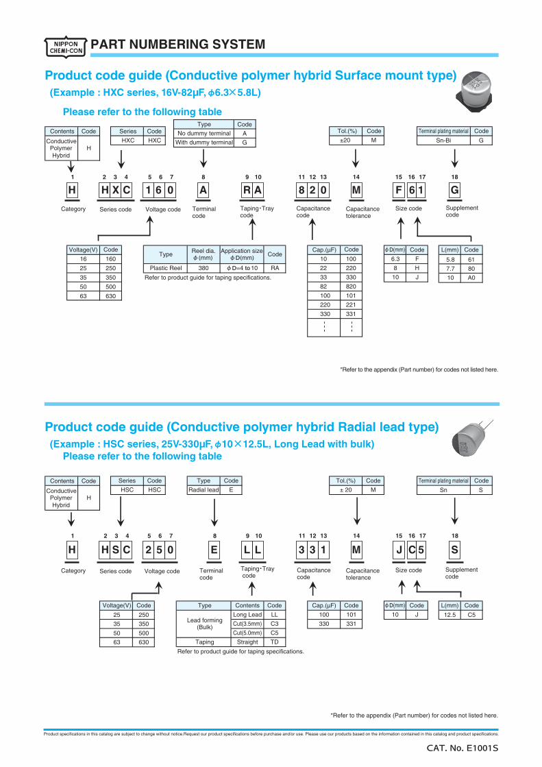
(Example : HXC series, 16V-82µF,φ6.3×5.8L)
Product code guide (Conductive polymer hybrid Surface mount type)
Please refer to the following table
Code
100
220
330
820
101
221
331
160
250
350
500
630
16
25
35
50
63
1 2 3 4 5 6 7 8 9 10 11 12 13 14 15 16 17 18
Refer to product guide for taping specifications.
*Refer to the appendix (Part number) for codes not listed here.
35
25
Voltage(V)
M
CodeType
HSC
Series Tol.(%)
350
250
63
50
630
500
S1 C
± 20E
Terminal plating material Code
Sn S
L
Radial lead
2
CodeCap.(µF)
M3
ContentsType
Long Lead
Cut(3.5mm)
LLLead forming
(Bulk) C3
Straight
Cut(5.0mm)
Taping
C5
10 12.5 C5100
331330
Code
H
CodeL(mm)φD(mm)
Category Series code Capacitancecode
Terminalcode
Taping・Tray code
Voltage code Capacitancetolerance
Size code Supplementcode
(Example : HSC series, 25V-330µF,φ10×12.5L, Long Lead with bulk)
Product code guide (Conductive polymer hybrid Radial lead type)
Please refer to the following table
Code
HSC
Code
5J3LE05CSH
Code
TD
Code
101 J
Type
No dummy terminal
With dummy terminal
Code
A
G
CAT. No. E1001S
PART NUMBERING SYSTEM
Product specifications in this catalog are subject to change without notice.Request our product specifications before purchase and/or use. Please use our products based on the information contained in this catalog and product specifications.
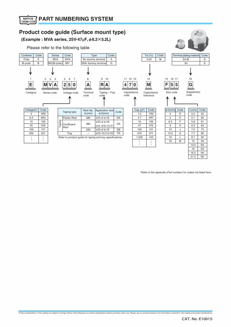
(Example : MVA series, 25V-47µF, φ6.3×5.2L)
Product code guide (Surface mount type)
Please refer to the following table
Refer to product guide for taping and tray specifications.
*Refer to the appendix (Part number) for codes not listed here.
Contents
Polar
Bi-polar
No dummy terminal
With dummy terminal
Type
MV-
MVA
Series
S
Terminal plating material
Sn-Bi
Sn
Code
GA
G
61
63
7.0
7.7
73
80
6.3
G5
K
L
A0
8.7
10
90
E0
H0
N0
16.5
21.5
13.5
16
471
102
M
φD=4 to 18
Tray
5
12.5
16
18
6.3100
φD=12.5 to 18
Tol.(%)
±20
Code
6R3
101
250
E
B
Code
MV(Bi-polar)
251
10
Tap
ing
60
5.2
TR-
5.7
F
101
5.8100
J
Code
5541R0
10
Cap.(µF)
1.0
4.7
470
E
8
D
4R7
H
380
47DA380
DB
RA
470
4R0
6.3
Voltage(V)
4
1,000
100
Reel dia.φ(mm)
Application sizeφD(mm) Code
330
φD=4 to 18
(not φD=12.5)
10
25
Taping type
CardboardReel
Plastic Reel
100
250
Category Series code Capacitancecode
Terminalcode
Taping・Traycode
Voltage code Capacitancetolerance
Size code Supplementcode
Code
MVA
Code
M
Code
φD=4 to 18
Code φD(mm) CodeL(mm)
1 11
M2 A0 G57AVE M1098765432 18171615141312
A R5 54 F0
CAT. No. E1001S
PART NUMBERING SYSTEM
Product specifications in this catalog are subject to change without notice.Request our product specifications before purchase and/or use. Please use our products based on the information contained in this catalog and product specifications.
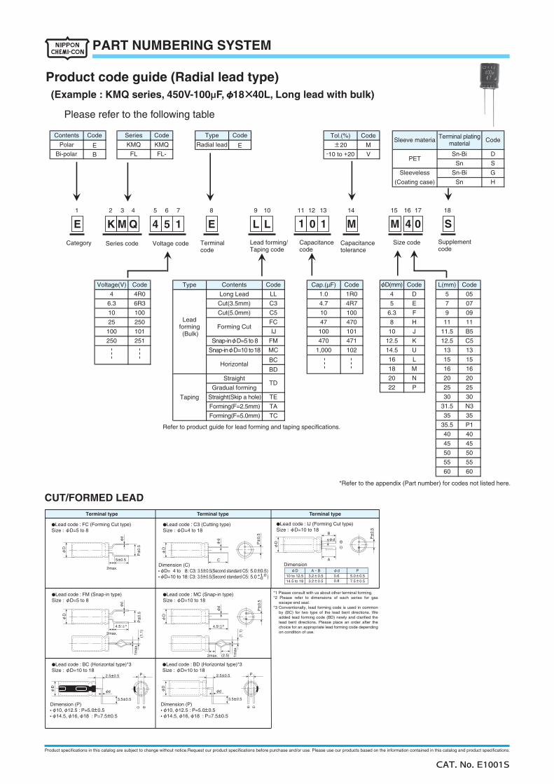
(Example : KMQ series, 450V-100µF,φ18×40L, Long lead with bulk)
Please refer to the following table
Refer to product guide for lead forming and taping specifications.
*Refer to the appendix (Part number) for codes not listed here.
KMQ
CodeType
±20Radial lead
(Coating case)
Terminal platingmaterial
Sn
Contents
Polar
Series
KMQ
25
100
250
CodeSleeve materia
12.5
Contents
D
8
Voltage(V)
4
Type
Leadforming (Bulk)
6.3
10
Long Lead
Cut(3.5mm)
Cut(5.0mm)
4.7
H
4
10
47
100
Forming(F=2.5mm)
Horizontal
Straight
Gradual forming
Forming Cut
Forming(F=5.0mm)
Taping
Snap-inφD=5 to 8
Snap-inφD=10 to 18
6R3
Straight(Skip a hole)
50
55
60
LL
C3
C5
FC
IJ
35
P1
40
45
16
11
B5
25
13
15
50
55
60
35
35.5
40
45
30
31.5
2020
25
30
N3
N
P
11
11.5
13
15
16
K
U
L
M
22
5
12.5
14.5
16
18
20
6.3100 F
H
-10 to +20
470
E
1.0
Bi-polar
4R0
FL
Code
M
D
S
VPET
L(mm)φD(mm) CodeCode
GSleeveless
Sn-Bi
Sn
Sn-Bi
1R0
4R7
100
TE
TA
FM
MC
251
101
250
TC
TD
471
102
470
1,000
BC
BD
05
07
09
5
7
101 10
9
Category Series code Capacitancecode
Terminalcode
Lead forming/Taping code
Voltage code Capacitancetolerance
Size code Supplementcode
Code
E
B
Code
FL-E
Tol.(%)
Code Cap.(µF)Code
J
Code
C5
Product code guide (Radial lead type)
1 11
S0M 1E 1L4 4M2 3 4 5 6 7 8 9 10
K Q 5 E L12 13 14 15 16 17 18
0 1 M
CUT/FORMED LEAD
5±0.5
2max.
P±
0.5
φD
φd
●Lead code : FC (Forming Cut type)Size : φD=5 to 8
●Lead code : C3 (Cutting type)Size : φD=4 to 18
●Lead code : MC (Snap-in type)Size : φD=10 to 18
●Lead code : FM (Snap-in type)Size : φD=5 to 8
●Lead code : BC (Horizontal type)*3Size : φD=10 to 18
4.5
2max.
P±
0.5
φD
φd
+1.0- 0
(1.1
)
1max
.
Dimension (P)●φ10,φ12.5 : P=5.0±0.5●φ14.5,φ16,φ18 : P=7.5±0.5
Dimension (C)●φD= 4 to 8: C3: 3.5±0.5(Second standard C5: 5.0±0.5) ●φD=10 to 18: C3: 3.5±0.5(Second standard C5: 5.0 ) +1.0
-0
Terminal type Terminal type Terminal type
●Lead code : IJ (Forming Cut type)Size : φD=10 to 18
Dimension φD
10 to 12.514.5 to 18
φd0.60.8
P5.0±0.57.5±0.5
A・B3.2±0.53.2±0.5
●Lead code : BD (Horizontal type)*3Size : φD=10 to 18
Dimension (P)●φ10,φ12.5 : P=5.0±0.5●φ14.5,φ16,φ18 : P=7.5±0.5
*1 Please consult with us about other terminal forming.*2 Please refer to dimensions of each series for gas
escape end seal.*3 Conventionally, lead forming code is used in common
by (BC) for two type of the lead bent directions. We added lead forming code (BD) newly and clarified the lead bent directions. Please place an order after the choice for an appropriate lead forming code depending on condition of use.
2.5±0.5
3.5±0.5
φd
P
φD
2.5±0.5
3.5±0.5
φdφD
4.5
φD
φd
+1.0- 0
(1.1
)
1max
.
(2.5)2max.
C
φD
φd
P±
0.5
φD
A
B
φd
P±
0.5
P
P±
0.5
CAT. No. E1001S
PART NUMBERING SYSTEM
Product specifications in this catalog are subject to change without notice.Request our product specifications before purchase and/or use. Please use our products based on the information contained in this catalog and product specifications.
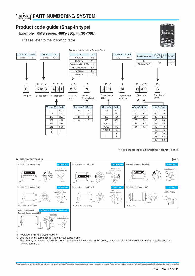
(Example : KMS series, 400V-330µF,φ30×30L)
Product code guide (Snap-in type)
Please refer to the following table
1 2 3 4 5 6 7 8 9 10 11 12 13 14 15 16 17 18
*Refer to the appendix (Part number) for codes not listed here.
Snap-in
Horizontal
Flat terminal for PCB
For Connector
LC
Straight VR
LI
LR
MSleeve material
VS
Type
Snap-in
Tol.(%)Code
SPET
MSn
Pb-free PVC
Terminal platingmaterial Code
250
315
35
40
45
50
6060
30
35
40
45
50
55
30
25
100
251
250
3
D
T101
2
390
470
101
3B1
100
6R3
472
103
1021,000
4,700
10,000
A
25.4
471
35
470
22
Q
R
P
30
100
47
15
20
25
20
15
25
L(mm)
20
3
N
R
Contents
Polar
φD(mm)
±20E
MKE 33
Code
4
N
S
N
0
1
CodeTerminal #
6.3
10
CodeCodeCap.(µF)Code
39
Voltage(V)
B40
Category Series code Capacitancecode
Terminalcode
Voltage code Capacitancetolerance
Size code Supplementcode
Dummyterminal code
CodeSeriesCode
KMSKMS
VN
Code
S0M1SV10S
55
For more details, refer to Product Guide.
Available terminals [mm]
Terminal, Dummy code : VND
Vent *1
A
B
C
22.5
6060
B : Positive, A, C : DummyB : Positive, A, C : Dummy
Terminal, Dummy code : LIN
D=φ50Terminal, Dummy code : LISTerminal, Dummy code : VRD
Vent *114.2
5
2-1.2×6
4.2
4.0Vent
*1
+0.2-0.1
A
Vent*1
A
B
C
PC board pin-out(View from Solder side)
22.5
4-φ2 4-φ2
2-φ2
6060
15.5
3-1.5×6.5
26.8
11.0
A : Dummy
D=φ22 toφ35 D=φ30 toφ40
D=φ35, φ40D=φ35, φ40
Terminal, Dummy code : VNN
10
2-φ25.8±14.5±1
5.5±1 5.8±1
3±18±1
φD
+1m
ax.
φD
+1m
ax.
φD
+1m
ax.
Terminal, Dummy code : VEN
Vent
PC board pin-out(View from Solder side)
PC board pin-out(View from Solder side)
PC board pin-out(View from Solder side)
PC board pin-out(View from Solder side)
PC board pin-out(View from Solder side)
PC board pin-out(View from Solder side)
D=φ30, φ35
4±1
φD
+1m
ax.
φD
+1m
ax.
φD
+1m
ax.
φD
+1m
ax.
Vent *1
Horizontal mountingTerminal, Dummy code : LCN
D=φ20×30 to 50L, φ22×30 to 50L
Vent
*1
1.5±0.1
Negative mark
8
*1 2-φ2
3.3
1-φ2.5min
10
4.75
*1 Negative terminal : Mesh marking*2 Use the dummy terminals for mechanical support only.
The dummy terminals must not be connected to any circuit trace on PC board, be sure to electrically isolate from the negative and the positive terminals.
CAT. No. E1001S
PART NUMBERING SYSTEM
Product specifications in this catalog are subject to change without notice.Request our product specifications before purchase and/or use. Please use our products based on the information contained in this catalog and product specifications.
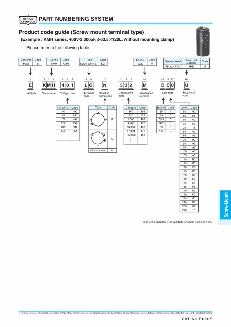
(Example : KMH series, 400V-3,300µF,φ63.5×120L, Without mounting clamp)
Product code guide (Screw mount terminal type)
Please refer to the following table
100
Code
U±20 M
Tol.(%) Code
PPE
Sleeve Material
Pb-free PVC
Code
LG
Type
Screw terminal
F
Without clamp
5C1
104
47,000
100,000
G
C
100473
101
89
472
10,0003B1
B
251
103
250
KMHE
CodeContents
Polar
Series Code
KMH
C
76.2
470
1,000
E4,700
471
102
50
63.5
CodeφD(mm)
A100 10110
25
Voltage(V)
100
250
315
525
Category Series code Capacitancecode
Terminalcode
Mountingclamp code
Voltage code Capacitancetolerance
Size code Supplementcode
CodeCap.(µF)CodeTypeCode
35
D
N
1 2 3 4 5 6 7 8 9 10 11 12 13 14 15 16 17 18
G4 0 1 U03 M3E MK H CD2NL
*Refer to the appendix (Part number) for codes not listed here.
N0
R0
T0
H0
K0
A5
220
250
270
E5
F5
B5
80
85
C5
96
A0
145
155
170
190
M0210
130
140
C0120
125
D0
E0
80
85
96
100
105
115
75
50
60
75
60
50
5555
L(mm)
6565
9090
9595
B0110
Code
Plastic diskMaterial
CAT. No. E1001S
PART NUMBERING SYSTEM
Scre
w-M
ount
Product specifications in this catalog are subject to change without notice.Request our product specifications before purchase and/or use. Please use our products based on the information contained in this catalog and product specifications.
Inverter-use screw terminal, 85℃
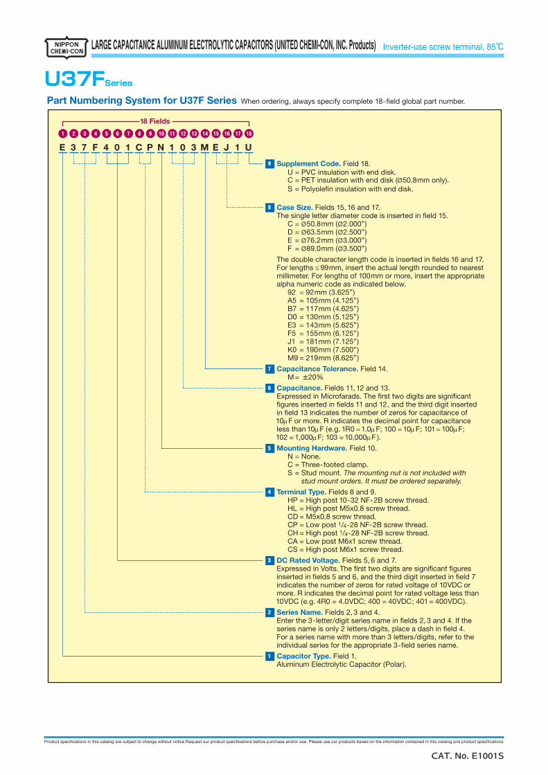
U37FSeries
Supplement Code. Field 18.
C = PET insulation with end disk (U = PVC insulation with end disk.
Ø50.8mm only).S = Polyole�n insulation with end disk.
Case Size. Fields 15, 16 and 17.The single letter diameter code is inserted in �eld 15.
C = Ø50.8mm (Ø2.000”)D = Ø63.5mm (Ø2.500”)E = Ø76.2mm (Ø3.000”)F = Ø89.0mm (Ø3.500”)
The double character length code is inserted in �elds 16 and 17.For lengths ≤99mm, insert the actual length rounded to nearestmillimeter. For lengths of 100mm or more, insert the appropriate alpha numeric code as indicated below.
92 = 92mm (3.625”)A5 = 105mm (4.125”)B7 = 117mm (4.625”)D0 = 130mm (5.125”)E3 = 143mm (5.625”)F5 = 155mm (6.125”)J1 = 181mm (7.125”)K0 = 190mm (7.500”)M9 = 219mm (8.625”)
Capacitance Tolerance. Field 14.M= ±20%
Capacitance. Fields 11, 12 and 13. Expressed in Microfarads. The �rst two digits are signi�cant �gures inserted in �elds 11 and 12, and the third digit inserted in �eld 13 indicates the number of zeros for capacitance of 10µF or more. R indicates the decimal point for capacitance less than 10µF (e.g. 1R0 =1.0µF; 100 = 10µF; 101= 100µF; 102 = 1,000µF; 103 = 10,000µF ).
Mounting Hardware. Field 10.N = None.C = Three-footed clamp.S = Stud mount. The mounting nut is not included with
stud mount orders. It must be ordered separately.
Terminal Type. Fields 8 and 9.HP = High post 10-32 NF-2B screw thread.HL = High post M5x0.8 screw thread.CD = M5x0.8 screw thread.CP = Low post 1/4-28 NF-2B screw thread.CH = High post 1/4-28 NF-2B screw thread.CA = Low post M6x1 screw thread.CS = High post M6x1 screw thread.
DC Rated Voltage. Fields 5, 6 and 7.Expressed in Volts. The �rst two digits are signi�cant �gures inserted in �elds 5 and 6, and the third digit inserted in �eld 7 indicates the number of zeros for rated voltage of 10VDC or more. R indicates the decimal point for rated voltage less than10VDC (e.g. 4R0 = 4.0VDC; 400 = 40VDC; 401 = 400VDC).
Series Name. Fields 2, 3 and 4.Enter the 3-letter/digit series name in �elds 2, 3 and 4. If the series name is only 2 letters/digits, place a dash in �eld 4. For a series name with more than 3 letters/digits, refer to the individual series for the appropriate 3-�eld series name.
Capacitor Type. Field 1.Aluminum Electrolytic Capacitor (Polar).
Part Numbering System for U37F Series When ordering, always specify complete 18-�eld global part number.
E 3 7 F 4 0 1 C P N 1 0 3 M E J 1 U
1716151413121110987654321 18
9
8
7
6
5
4
3
2
1
18 Fields
CAT. No. E1001S
LARGE CAPACITANCE ALUMINUM ELECTROLYTIC CAPACITORS (UNITED CHEMI-CON, INC. Products)
Product specifications in this catalog are subject to change without notice.Request our product specifications before purchase and/or use. Please use our products based on the information contained in this catalog and product specifications.
Inverter-use screw terminal, 85℃
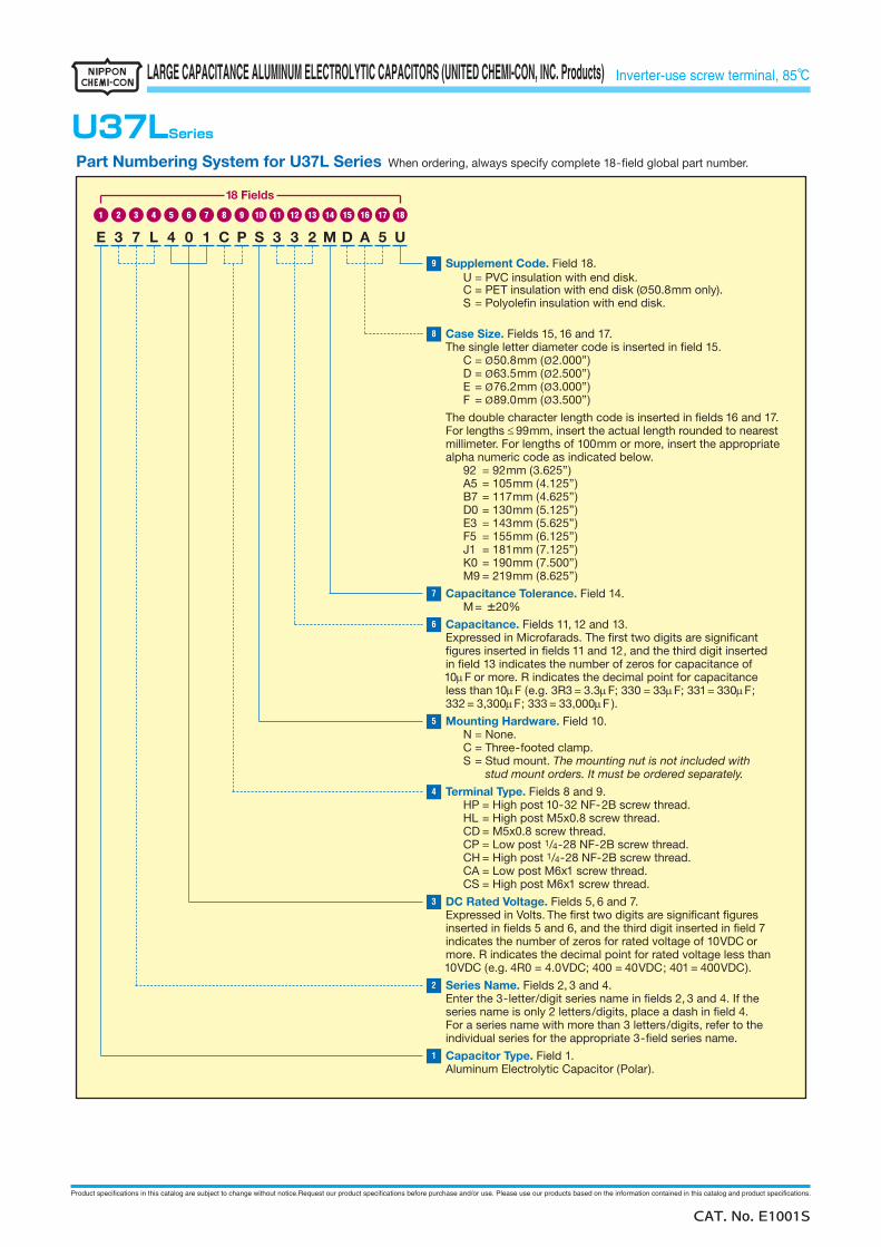
U37LSeries
Supplement Code. Field 18.
C = PET insulation with end disk (U = PVC insulation with end disk.
Ø50.8mm only).
Case Size. Fields 15, 16 and 17.The single letter diameter code is inserted in �eld 15.
C = Ø50.8mm (Ø2.000”)D = Ø63.5mm (Ø2.500”)E = Ø76.2mm (Ø3.000”)F = Ø89.0mm (Ø3.500”)
The double character length code is inserted in �elds 16 and 17.For lengths ≤99mm, insert the actual length rounded to nearestmillimeter. For lengths of 100mm or more, insert the appropriate alpha numeric code as indicated below.
92 = 92mm (3.625”)A5 = 105mm (4.125”)B7 = 117mm (4.625”)D0 = 130mm (5.125”)E3 = 143mm (5.625”)F5 = 155mm (6.125”)J1 = 181mm (7.125”)K0 = 190mm (7.500”)M9 = 219mm (8.625”)
Capacitance Tolerance. Field 14.M= ±20%
Capacitance. Fields 11, 12 and 13. Expressed in Microfarads. The �rst two digits are signi�cant �gures inserted in �elds 11 and 12, and the third digit inserted in �eld 13 indicates the number of zeros for capacitance of 10µF or more. R indicates the decimal point for capacitance less than 10µF (e.g. 3R3 = 3.3µF; 330 = 33µF; 331= 330µF; 332 = 3,300µF; 333 = 33,000µF ).
Mounting Hardware. Field 10.N = None.C = Three-footed clamp.S = Stud mount. The mounting nut is not included with
stud mount orders. It must be ordered separately.
Terminal Type. Fields 8 and 9.HP = High post 10-32 NF-2B screw thread.HL = High post M5x0.8 screw thread.CD = M5x0.8 screw thread.CP = Low post 1/4-28 NF-2B screw thread.CH = High post 1/4-28 NF-2B screw thread.CA = Low post M6x1 screw thread.CS = High post M6x1 screw thread.
DC Rated Voltage. Fields 5, 6 and 7.Expressed in Volts. The �rst two digits are signi�cant �gures inserted in �elds 5 and 6, and the third digit inserted in �eld 7 indicates the number of zeros for rated voltage of 10VDC or more. R indicates the decimal point for rated voltage less than10VDC (e.g. 4R0 = 4.0VDC; 400 = 40VDC; 401 = 400VDC).
Series Name. Fields 2, 3 and 4.Enter the 3-letter/digit series name in �elds 2, 3 and 4. If the series name is only 2 letters/digits, place a dash in �eld 4. For a series name with more than 3 letters/digits, refer to the individual series for the appropriate 3-�eld series name.
Capacitor Type. Field 1.Aluminum Electrolytic Capacitor (Polar).
Part Numbering System for U37L Series When ordering, always specify complete 18-�eld global part number.
E 3 7 L 4 0 1 C P S 3 3 2 M D A 5 U
1716151413121110987654321 18
9
8
7
6
5
4
3
2
1
18 Fields
S = Polyole�n insulation with end disk.
CAT. No. E1001S
LARGE CAPACITANCE ALUMINUM ELECTROLYTIC CAPACITORS (UNITED CHEMI-CON, INC. Products)

Product specifications in this catalog are subject to change without notice.Request our product specifications before purchase and/or use. Please use our products based on the information contained in this catalog and product specifications.
Inverter-use screw terminal, 85℃
U37XSeries
Supplement Code. Field 18.
C = PET insulation with end disk (U = PVC insulation with end disk.
Ø50.8mm only).
Case Size. Fields 15, 16 and 17.The single letter diameter code is inserted in �eld 15.
C = Ø50.8mm (Ø2.000”)D = Ø63.5mm (Ø2.500”)E = Ø76.2mm (Ø3.000”)F = Ø89.0mm (Ø3.500”)
The double character length code is inserted in �elds 16 and 17.For lengths ≤99mm, insert the actual length rounded to nearestmillimeter. For lengths of 100mm or more, insert the appropriate alpha numeric code as indicated below.
92 = 92mm (3.625”)A5 = 105mm (4.125”)B7 = 117mm (4.625”)D0 = 130mm (5.125”)E3 = 143mm (5.625”)F5 = 155mm (6.125”)J1 = 181mm (7.125”)K0 = 190mm (7.500”)M9 = 219mm (8.625”)
Capacitance Tolerance. Field 14.M=
Capacitance. Fields 11, 12 and 13. Expressed in Microfarads. The �rst two digits are signi�cant �gures inserted in �elds 11 and 12, and the third digit inserted in �eld 13 indicates the number of zeros for capacitance of 10µF or more. R indicates the decimal point for capacitance less than 10µF (e.g. 4R7= 4.7µF; 470 = 47µF; 471= 470µF; 472 = 4,700µF; 473 = 47,000µF ).
Mounting Hardware. Field 10.N = None.C = Three-footed clamp.S = Stud mount. The mounting nut is not included with
stud mount orders. It must be ordered separately.
Terminal Type. Fields 8 and 9.HP = High post 10-32 NF-2B screw thread.HL = High post M5x0.8 screw thread.CD = M5x0.8 screw thread.CP = Low post 1/4-28 NF-2B screw thread.CH = High post 1/4-28 NF-2B screw thread.CA = Low post M6x1 screw thread.CS = High post M6x1 screw thread.
DC Rated Voltage. Fields 5, 6 and 7.Expressed in Volts. The �rst two digits are signi�cant �gures inserted in �elds 5 and 6, and the third digit inserted in �eld 7 indicates the number of zeros for rated voltage of 10VDC or more. R indicates the decimal point for rated voltage less than10VDC (e.g. 4R0 = 4.0VDC; 400 = 40VDC; 401 = 400VDC).
Series Name. Fields 2, 3 and 4.Enter the 3-letter/digit series name in �elds 2, 3 and 4. If the series name is only 2 letters/digits, place a dash in �eld 4. For a series name with more than 3 letters/digits, refer to the individual series for the appropriate 3-�eld series name.
Capacitor Type. Field 1.Aluminum Electrolytic Capacitor (Polar).
Part Numbering System for U37X Series When ordering, always specify complete 18-�eld global part number.
E 3 7 X 4 0 1 C P N 4 7 2 M E A 5 U
1716151413121110987654321 18
9
8
7
6
5
4
3
2
1
18 Fields
±20%
S = Polyole�n insulation with end disk.
CAT. No. E1001S
LARGE CAPACITANCE ALUMINUM ELECTROLYTIC CAPACITORS (UNITED CHEMI-CON, INC. Products)
Product specifications in this catalog are subject to change without notice.Request our product specifications before purchase and/or use. Please use our products based on the information contained in this catalog and product specifications.
Inverter-use screw terminal, 105℃
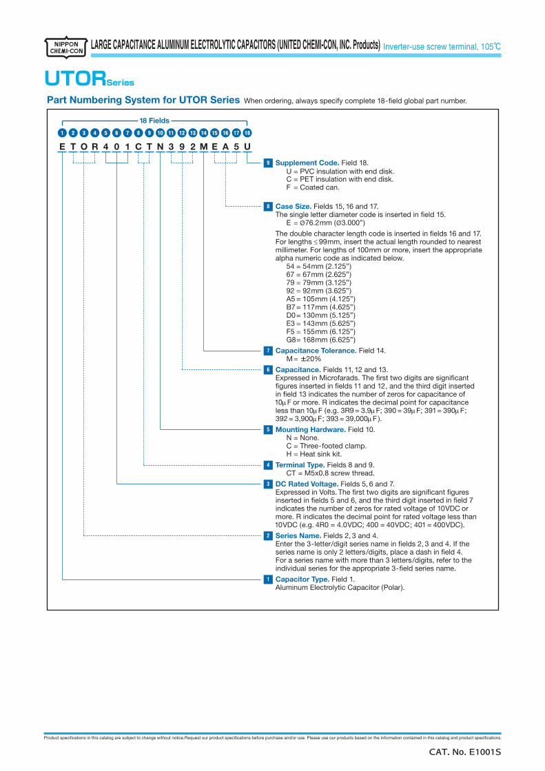
UTORSeries
Supplement Code. Field 18.
C = PET insulation with end disk.U = PVC insulation with end disk.
F = Coated can.
Case Size. Fields 15, 16 and 17.The single letter diameter code is inserted in �eld 15.
E = Ø76.2mm (Ø3.000”)
The double character length code is inserted in �elds 16 and 17.For lengths ≤99mm, insert the actual length rounded to nearestmillimeter. For lengths of 100mm or more, insert the appropriate alpha numeric code as indicated below.
54 = 54mm (2.125”)67 = 67mm (2.625”)79 = 79mm (3.125”)92 = 92mm (3.625”)A5 = 105mm (4.125”)B7= 117mm (4.625”)D0= 130mm (5.125”)E3 = 143mm (5.625”)F5 = 155mm (6.125”)G8= 168mm (6.625”)
Capacitance Tolerance. Field 14.M= ±20%
Capacitance. Fields 11, 12 and 13. Expressed in Microfarads. The �rst two digits are signi�cant �gures inserted in �elds 11 and 12, and the third digit inserted in �eld 13 indicates the number of zeros for capacitance of 10µF or more. R indicates the decimal point for capacitance less than 10µF (e.g. 3R9 = 3.9µF; 390 = 39µF; 391= 390µF; 392 = 3,900µF; 393 = 39,000µF ).
Mounting Hardware. Field 10.N = None.C = Three-footed clamp.H = Heat sink kit.
Terminal Type. Fields 8 and 9.CT = M5x0.8 screw thread.
DC Rated Voltage. Fields 5, 6 and 7.Expressed in Volts. The �rst two digits are signi�cant �gures inserted in �elds 5 and 6, and the third digit inserted in �eld 7 indicates the number of zeros for rated voltage of 10VDC or more. R indicates the decimal point for rated voltage less than10VDC (e.g. 4R0 = 4.0VDC; 400 = 40VDC; 401 = 400VDC).
Series Name. Fields 2, 3 and 4.Enter the 3-letter/digit series name in �elds 2, 3 and 4. If the series name is only 2 letters/digits, place a dash in �eld 4. For a series name with more than 3 letters/digits, refer to the individual series for the appropriate 3-�eld series name.
Capacitor Type. Field 1.Aluminum Electrolytic Capacitor (Polar).
Part Numbering System for UTOR Series When ordering, always specify complete 18-�eld global part number.
E T O R 4 0 1 C T N 3 9 2 M E A 5 U
1716151413121110987654321 18
9
8
7
6
5
4
3
2
1
18 Fields
CAT. No. E1001S
LARGE CAPACITANCE ALUMINUM ELECTROLYTIC CAPACITORS (UNITED CHEMI-CON, INC. Products)

Appendix

Product specifications in this catalog are subject to change without notice.Request our product specifications before purchase and/or use. Please use our products based on the information contained in this catalog and product specifications.
Appendix (Part number)◆Capacitance code
* How to use the table
1st For less than 10µF, a decimal point position is displayed with R.For 10µF or more, capacitance code is set to the first 2 digits and index (1digit).Treatment of fraction (Refer to the table) 2nd Cap. Value
Capacitance value part Example of conversion
2nd1st
Real cap. The first2 digits
Treatmentof fraction
Code1 2 3 4 5 6 7 8 9 11th 12th 13th
0 10.0 20.0 30.0 40.0 50.0 60.0 70.0 80.0 90.0 10.0µF → 10.0 → 10.0 → 1 0 0A 10.5 20.5 30.5 40.5 50.5 60.5 70.5 80.5 90.5 10.1µF → 10.1 → 10.0 → 1 0 01 11.0 21.0 31.0 41.0 51.0 61.0 71.0 81.0 91.0 10.2µF → 10.2 → 10.0 → 1 0 0B 11.5 21.5 31.5 41.5 51.5 61.5 71.5 81.5 91.5 10.3µF → 10.3 → 10.5 → 1 A 02 12.0 22.0 32.0 42.0 52.0 62.0 72.0 82.0 92.0 10.4µF → 10.4 → 10.5 → 1 A 0C 12.5 22.5 32.5 42.5 52.5 62.5 72.5 82.5 92.5 10.5µF → 10.5 → 10.5 → 1 A 03 13.0 23.0 33.0 43.0 53.0 63.0 73.0 83.0 93.0 10.6µF → 10.6 → 10.5 → 1 A 0D 13.5 23.5 33.5 43.5 53.5 63.5 73.5 83.5 93.5 10.7µF → 10.7 → 10.5 → 1 A 04 14.0 24.0 34.0 44.0 54.0 64.0 74.0 84.0 94.0 10.8µF → 10.8 → 11.0 → 1 1 0E 14.5 24.5 34.5 44.5 54.5 64.5 74.5 84.5 94.5 10.9µF → 10.9 → 11.0 → 1 1 05 15.0 25.0 35.0 45.0 55.0 65.0 75.0 85.0 95.0 11.0µF → 11.0 → 11.0 → 1 1 0F 15.5 25.5 35.5 45.5 55.5 65.5 75.5 85.5 95.5 132µF → 13.2 → 13.0 → 1 3 16 16.0 26.0 36.0 46.0 56.0 66.0 76.0 86.0 96.0 133µF → 13.3 → 13.5 → 1 D 1G 16.5 26.5 36.5 46.5 56.5 66.5 76.5 86.5 96.5 167µF → 16.7 → 16.5 → 1 G 17 17.0 27.0 37.0 47.0 57.0 67.0 77.0 87.0 97.0 168µF → 16.8 → 17.0 → 1 7 1H 17.5 27.5 37.5 47.5 57.5 67.5 77.5 87.5 97.5 1110µF → 11.1 → 11.0 → 1 1 28 18.0 28.0 38.0 48.0 58.0 68.0 78.0 88.0 98.0 1340µF → 13.4 → 13.5 → 1 D 2J 18.5 28.5 38.5 48.5 58.5 68.5 78.5 88.5 98.5 13200µF → 13.2 → 13.0 → 1 3 39 19.0 29.0 39.0 49.0 59.0 69.0 79.0 89.0 99.0 13600µF → 13.6 → 13.5 → 1 D 3K 19.5 29.5 39.5 49.5 59.5 69.5 79.5 89.5 99.5 270000µF → 27.0 → 27.0 → 2 7 4
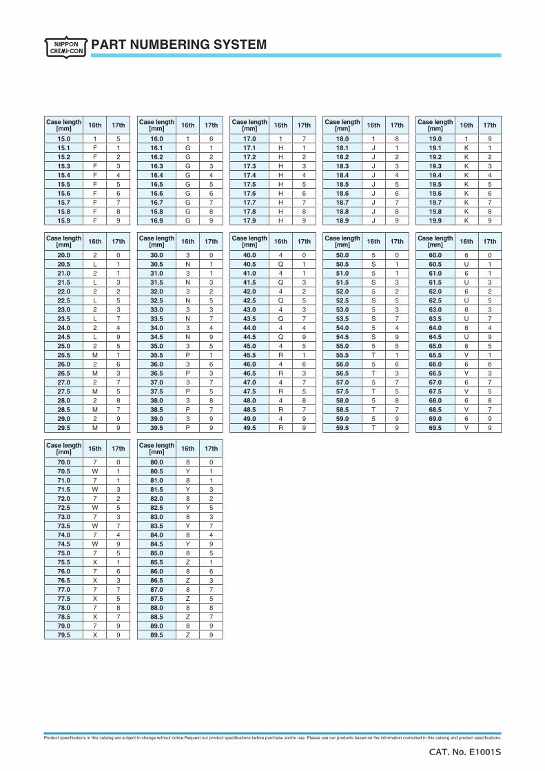
◆Case length (Radial lead type)Case length
[mm] 16th 17th Case length[mm] 16th 17th Case length
[mm] 16th 17th Case length[mm] 16th 17th Case length
[mm] 16th 17th
0.0 - - 1.0 0 1 2.0 0 2 3.0 0 3 4.0 0 40.1 0 B 1.1 1 B 2.1 2 B 3.1 3 B 4.1 4 B0.2 0 C 1.2 1 C 2.2 2 C 3.2 3 C 4.2 4 C0.3 0 D 1.3 1 D 2.3 2 D 3.3 3 D 4.3 4 D0.4 0 E 1.4 1 E 2.4 2 E 3.4 3 E 4.4 4 E0.5 0 F 1.5 1 F 2.5 2 F 3.5 3 F 4.5 4 F0.6 0 G 1.6 1 G 2.6 2 G 3.6 3 G 4.6 4 G0.7 0 H 1.7 1 H 2.7 2 H 3.7 3 H 4.7 4 H0.8 0 J 1.8 1 J 2.8 2 J 3.8 3 J 4.8 4 J0.9 0 K 1.9 1 K 2.9 2 K 3.9 3 K 4.9 4 K
Case length[mm] 16th 17th Case length
[mm] 16th 17th Case length[mm] 16th 17th Case length
[mm] 16th 17th Case length[mm] 16th 17th
5.0 0 5 6.0 0 6 7.0 0 7 8.0 0 8 9.0 0 95.1 5 B 6.1 6 B 7.1 7 B 8.1 8 B 9.1 9 B5.2 5 C 6.2 6 C 7.2 7 C 8.2 8 C 9.2 9 C5.3 5 D 6.3 6 D 7.3 7 D 8.3 8 D 9.3 9 D5.4 5 E 6.4 6 E 7.4 7 E 8.4 8 E 9.4 9 E5.5 5 F 6.5 6 F 7.5 7 F 8.5 8 F 9.5 9 F5.6 5 G 6.6 6 G 7.6 7 G 8.6 8 G 9.6 9 G5.7 5 H 6.7 6 H 7.7 7 H 8.7 8 H 9.7 9 H5.8 5 J 6.8 6 J 7.8 7 J 8.8 8 J 9.8 9 J5.9 5 K 6.9 6 K 7.9 7 K 8.9 8 K 9.9 9 K
Case length[mm] 16th 17th Case length
[mm] 16th 17th Case length[mm] 16th 17th Case length
[mm] 16th 17th Case length[mm] 16th 17th
10.0 1 0 11.0 1 1 12.0 1 2 13.0 1 3 14.0 1 410.1 A 1 11.1 B 1 12.1 C 1 13.1 D 1 14.1 E 110.2 A 2 11.2 B 2 12.2 C 2 13.2 D 2 14.2 E 210.3 A 3 11.3 B 3 12.3 C 3 13.3 D 3 14.3 E 310.4 A 4 11.4 B 4 12.4 C 4 13.4 D 4 14.4 E 410.5 A 5 11.5 B 5 12.5 C 5 13.5 D 5 14.5 E 510.6 A 6 11.6 B 6 12.6 C 6 13.6 D 6 14.6 E 610.7 A 7 11.7 B 7 12.7 C 7 13.7 D 7 14.7 E 710.8 A 8 11.8 B 8 12.8 C 8 13.8 D 8 14.8 E 810.9 A 9 11.9 B 9 12.9 C 9 13.9 D 9 14.9 E 9
CAT. No. E1001S
PART NUMBERING SYSTEM
Product specifications in this catalog are subject to change without notice.Request our product specifications before purchase and/or use. Please use our products based on the information contained in this catalog and product specifications.
Case length[mm] 16th 17th Case length
[mm] 16th 17th Case length[mm] 16th 17th Case length
[mm] 16th 17th Case length[mm] 16th 17th
15.0 1 5 16.0 1 6 17.0 1 7 18.0 1 8 19.0 1 915.1 F 1 16.1 G 1 17.1 H 1 18.1 J 1 19.1 K 115.2 F 2 16.2 G 2 17.2 H 2 18.2 J 2 19.2 K 215.3 F 3 16.3 G 3 17.3 H 3 18.3 J 3 19.3 K 315.4 F 4 16.4 G 4 17.4 H 4 18.4 J 4 19.4 K 415.5 F 5 16.5 G 5 17.5 H 5 18.5 J 5 19.5 K 515.6 F 6 16.6 G 6 17.6 H 6 18.6 J 6 19.6 K 615.7 F 7 16.7 G 7 17.7 H 7 18.7 J 7 19.7 K 715.8 F 8 16.8 G 8 17.8 H 8 18.8 J 8 19.8 K 815.9 F 9 16.9 G 9 17.9 H 9 18.9 J 9 19.9 K 9
Case length[mm] 16th 17th Case length
[mm] 16th 17th Case length[mm] 16th 17th Case length
[mm] 16th 17th Case length[mm] 16th 17th
20.0 2 0 30.0 3 0 40.0 4 0 50.0 5 0 60.0 6 020.5 L 1 30.5 N 1 40.5 Q 1 50.5 S 1 60.5 U 121.0 2 1 31.0 3 1 41.0 4 1 51.0 5 1 61.0 6 121.5 L 3 31.5 N 3 41.5 Q 3 51.5 S 3 61.5 U 322.0 2 2 32.0 3 2 42.0 4 2 52.0 5 2 62.0 6 222.5 L 5 32.5 N 5 42.5 Q 5 52.5 S 5 62.5 U 523.0 2 3 33.0 3 3 43.0 4 3 53.0 5 3 63.0 6 323.5 L 7 33.5 N 7 43.5 Q 7 53.5 S 7 63.5 U 724.0 2 4 34.0 3 4 44.0 4 4 54.0 5 4 64.0 6 424.5 L 9 34.5 N 9 44.5 Q 9 54.5 S 9 64.5 U 925.0 2 5 35.0 3 5 45.0 4 5 55.0 5 5 65.0 6 525.5 M 1 35.5 P 1 45.5 R 1 55.5 T 1 65.5 V 126.0 2 6 36.0 3 6 46.0 4 6 56.0 5 6 66.0 6 626.5 M 3 36.5 P 3 46.5 R 3 56.5 T 3 66.5 V 327.0 2 7 37.0 3 7 47.0 4 7 57.0 5 7 67.0 6 727.5 M 5 37.5 P 5 47.5 R 5 57.5 T 5 67.5 V 528.0 2 8 38.0 3 8 48.0 4 8 58.0 5 8 68.0 6 828.5 M 7 38.5 P 7 48.5 R 7 58.5 T 7 68.5 V 729.0 2 9 39.0 3 9 49.0 4 9 59.0 5 9 69.0 6 929.5 M 9 39.5 P 9 49.5 R 9 59.5 T 9 69.5 V 9
Case length[mm] 16th 17th Case length
[mm] 16th 17th
70.0 7 0 80.0 8 070.5 W 1 80.5 Y 171.0 7 1 81.0 8 171.5 W 3 81.5 Y 372.0 7 2 82.0 8 272.5 W 5 82.5 Y 573.0 7 3 83.0 8 373.5 W 7 83.5 Y 774.0 7 4 84.0 8 474.5 W 9 84.5 Y 975.0 7 5 85.0 8 575.5 X 1 85.5 Z 176.0 7 6 86.0 8 676.5 X 3 86.5 Z 377.0 7 7 87.0 8 777.5 X 5 87.5 Z 578.0 7 8 88.0 8 878.5 X 7 88.5 Z 779.0 7 9 89.0 8 979.5 X 9 89.5 Z 9
CAT. No. E1001S
PART NUMBERING SYSTEM

Product specifications in this catalog are subject to change without notice.Request our product specifications before purchase and/or use. Please use our products based on the information contained in this catalog and product specifications.
◆Case length (Snap-in type / Screw mount terminal type)
Case length[mm] 16th 17th Case length
[mm] 16th 17th Case length[mm] 16th 17th Case length
[mm] 16th 17th Case length[mm] 16th 17th
20 2 0 30 3 0 40 4 0 50 5 0 60 6 021 2 1 31 3 1 41 4 1 51 5 1 61 6 122 2 2 32 3 2 42 4 2 52 5 2 62 6 223 2 3 33 3 3 43 4 3 53 5 3 63 6 324 2 4 34 3 4 44 4 4 54 5 4 64 6 425 2 5 35 3 5 45 4 5 55 5 5 65 6 526 2 6 36 3 6 46 4 6 56 5 6 66 6 627 2 7 37 3 7 47 4 7 57 5 7 67 6 728 2 8 38 3 8 48 4 8 58 5 8 68 6 829 2 9 39 3 9 49 4 9 59 5 9 69 6 9
Case length[mm] 16th 17th Case length
[mm] 16th 17th Case length[mm] 16th 17th Case length
[mm] 16th 17th Case length[mm] 16th 17th
70 7 0 80 8 0 90 9 0 100 A 0 110 B 071 7 1 81 8 1 91 9 1 101 A 1 111 B 172 7 2 82 8 2 92 9 2 102 A 2 112 B 273 7 3 83 8 3 93 9 3 103 A 3 113 B 374 7 4 84 8 4 94 9 4 104 A 4 114 B 475 7 5 85 8 5 95 9 5 105 A 5 115 B 576 7 6 86 8 6 96 9 6 106 A 6 116 B 677 7 7 87 8 7 97 9 7 107 A 7 117 B 778 7 8 88 8 8 98 9 8 108 A 8 118 B 879 7 9 89 8 9 99 9 9 109 A 9 119 B 9
Case length[mm] 16th 17th Case length
[mm] 16th 17th Case length[mm] 16th 17th Case length
[mm] 16th 17th Case length[mm] 16th 17th
120 C 0 130 D 0 140 E 0 150 F 0 160 G 0121 C 1 131 D 1 141 E 1 151 F 1 161 G 1122 C 2 132 D 2 142 E 2 152 F 2 162 G 2123 C 3 133 D 3 143 E 3 153 F 3 163 G 3124 C 4 134 D 4 144 E 4 154 F 4 164 G 4125 C 5 135 D 5 145 E 5 155 F 5 165 G 5126 C 6 136 D 6 146 E 6 156 F 6 166 G 6127 C 7 137 D 7 147 E 7 157 F 7 167 G 7128 C 8 138 D 8 148 E 8 158 F 8 168 G 8129 C 9 139 D 9 149 E 9 159 F 9 169 G 9
Case length[mm] 16th 17th Case length
[mm] 16th 17th Case length[mm] 16th 17th Case length
[mm] 16th 17th Case length[mm] 16th 17th
170 H 0 180 J 0 190 K 0 200 L 0 210 M 0171 H 1 181 J 1 191 K 1 201 L 1 211 M 1172 H 2 182 J 2 192 K 2 202 L 2 212 M 2173 H 3 183 J 3 193 K 3 203 L 3 213 M 3174 H 4 184 J 4 194 K 4 204 L 4 214 M 4175 H 5 185 J 5 195 K 5 205 L 5 215 M 5176 H 6 186 J 6 196 K 6 206 L 6 216 M 6177 H 7 187 J 7 197 K 7 207 L 7 217 M 7178 H 8 188 J 8 198 K 8 208 L 8 218 M 8179 H 9 189 J 9 199 K 9 209 L 9 219 M 9
Case length[mm] 16th 17th Case length
[mm] 16th 17th Case length[mm] 16th 17th Case length
[mm] 16th 17th
220 N 0 230 P 0 240 Q 0 250 R 0221 N 1 231 P 1 241 Q 1 251 R 1222 N 2 232 P 2 242 Q 2 252 R 2223 N 3 233 P 3 243 Q 3 253 R 3224 N 4 234 P 4 244 Q 4 254 R 4225 N 5 235 P 5 245 Q 5 255 R 5226 N 6 236 P 6 246 Q 6 256 R 6227 N 7 237 P 7 247 Q 7 257 R 7228 N 8 238 P 8 248 Q 8 258 R 8229 N 9 239 P 9 249 Q 9 259 R 9
CAT. No. E1001S
PART NUMBERING SYSTEM

Product specifications in this catalog are subject to change without notice.Request our product specifications before purchase and/or use. Please use our products based on the information contained in this catalog and product specifications.
◆Supplement codeConductive Polymer Aluminum Solid Capacitors (Chip and Radial lead type)Conductive Polymer Hybrid Aluminum Electrolytic Capacitors (Chip and Radial lead type)Aluminum Electrolytic Capacitors (Chip type)
Terminal plating material
Sn Sn-Bi
Coating case S G
Aluminum Electrolytic Capacitors (Radial lead and Snap-in type)
Terminal plating material
Sn Sn-Bi
Out
er s
leev
e PET S D
Coating case H G
Polyolefin L −
Pb-free PVC M −
* Standard design of "environmental friendly" snap-in are not equipped with a plastic disk on the top of the can case.We also produce snap-in type with "Plastic disk (PPE), PVC sleeve and Sn terminal plating".In this case, supplement code ((PPE) the 18th digit) is "U". When the material of the plastic disk is PVC, the code is "T".
Aluminum Electrolytic Capacitors (Screw mount terminal type)
Plastic disk material
PPE PVC
Out
er
slee
ve
Pb-free PVC U M
Polyolefin S −
PET − C
* Supplement code (the 18th digit) is also "S" when "Outer sleeve material: Polyolefin, Plastic disk material: PET".
CAT. No. E1001S
PART NUMBERING SYSTEM


![Specifications and Quantity Surveying [ARC318]drahmedelyamany.weebly.com/uploads/7/0/1/0/7010103/4... · Specifications • “Are written instructions concerning project requirement.”](https://img.pdfslide.net/doc/110x75/5a729a1c7f8b9aa7538db764/specifications-and-quantity-surveying-arc318drahmedelyamanyweeblycomuploads701070101034pdf.jpg)