Embed Size (px)
Citation preview

http://www.lxqqfy.com/ S-RockMite QRP Kit User Manual
S-RockMite QRP Kit
User Manual Revision V161101
Welcome to visit the home page www.lxqqfy.com to obtain the latest data.
1 / 23

http://www.lxqqfy.com/ S-RockMite QRP Kit User Manual
1. Introduction
This is a very small volume of simple 40 meter band micro-power amplitude telegraph
transceiver, Despite it's small size and DC receiver limitations, it is capable of working
several hundred miles when connected to a good 40 meter antenna.
There are many versions of "RockMite", "RockMite SWL", "RockMite PIC",
"RockMite 51", and “S-RockMite”. “S-RockMite” is so far the latest version. "RockMite 51"
and “S-RockMite” is designed by “LXQQFY.com”. The new product adds the following new
features.
The vertical resistance changed to horizontal resistance.
It do not distinguish between positive and negative input power.
Provide acrylic case.
Provide WIFI module options. Support automatic key and automatic transmitter.
Can connect the phone to change the configuration.
2. Specifications
Power supply: 9~13.8 Volts DC, >1A (Recommend the use of batteries)
Antenna: 50ohm, 7MHz, SWR<2.0
Receive: static current 60mA
Transmission power: 5W
Frequency: launch the vibration frequency,7023 KHZ
Receives the local oscillator frequency: about
7023-7023 KHZ work mode: the CW
KEY: Manual and automatic auto-detection
Automatic sending: ok
Config: the mobile phone application(WIFI)
case: acrylic
2 / 23

http://www.lxqqfy.com/ S-RockMite QRP Kit User Manual
3. Circuit principle
Reference schematic diagram.Receiving part is the core of a NE602,inside it includes an
oscillating circuit and a balanced mixer,antenna in the signal after 2 crystal filter,into the
mixer, The basic oscillation signal is sent out by the 9018 oscillation circuit, two signals
through mixing,directly put the CW signal frequency conversion for audio, NE602 output
audio and then sent to the NE5532 to do the active low-pass filter and audio amplification, so
that the whole process of the reception. it is called "DC receiver". 2N7000 field effect tube is
used for closing reception at launch. At the same time, the WIFI module generates the side
sound, which is output to the earphone. The launch part uses 9018 to do the oscillation
circuit, then the 8050 makes the buffer enlargement. 8050 is also used as a launch key
control, control transceiver circuit and signal switching. The last stage is composed of a
D882 class C amplifier, matched by 1:4 transformer, after LPF filter is connected with the
antenna.
The WIFI module is optional. If you do not use the WIFI module, you need to short circuit
the JP1, then "S-RockMite" == "RockMite" == Ordinary CW radio. If you use the WIFI
module, you need to unplug the JP1,then you can use the mobile phone configuration data.
4. Component selection
9018 magnification is about 130 , D882 magnification is about 200. T1 is 1:4
transmission line transformer, in FT37-43 iron and oxygen magnet ring bodies (black) using
0.51 mm paint envelope double hinge line in and around six times, then connecting a coil
with a head and a tail. T2 is the high frequency transformer, in FT37-43 iron and oxygen
magnet ring bodies (black) using 0.51 mm paint covered wire for winding, Primary 8 turn,
secondary 2 turn. L1 L2 is the high frequency filter inductance in T37-2 on the iron core is
circular and(red) using 16 to 0.5 mm enameled wire around.
3 / 23

http://www.lxqqfy.com/ S-RockMite QRP Kit User Manual
5. Production process
5.1 According to the list of components, check the number of components. Have tools,
Electric iron, Solder wire, and A multimeter on hand. Take welding from low to high order,
Recommend: Resistance -> Diode -> Capacitance -> Triode -> Crystal oscillator -> LED ->
Bridge rectifier -> Electrolytic capacitor -> Ic -> Inductor -> Magnet ring -> D882 -> Other.
4 / 23
http://www.lxqqfy.com/ S-RockMite QRP Kit User Manual
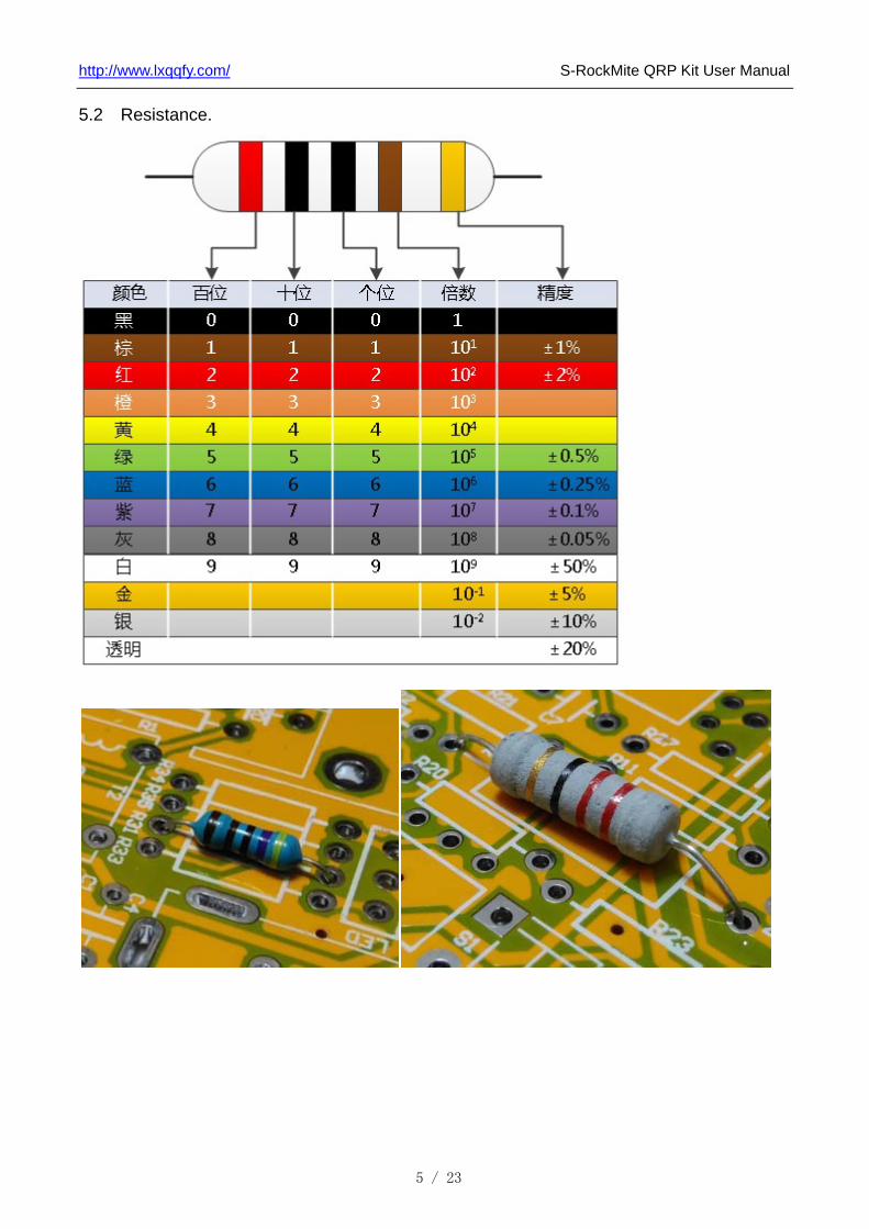
5.2 Resistance.
5 / 23

http://www.lxqqfy.com/ S-RockMite QRP Kit User Manual
5.3 Diode.
1N4001 1N4148
5.4 Capacitance.
0.1uF(104) 10nF(103) 1nF(102) 100pF(101) 33pF(33) 56pF(56) 470pF(471)
6 / 23

http://www.lxqqfy.com/ S-RockMite QRP Kit User Manual
5.5 Triode and FET.
5.6 Crystal oscillator.
5.7 LED.
7 / 23

http://www.lxqqfy.com/ S-RockMite QRP Kit User Manual
5.8 Bridge rectifier.
5.9 Electrolytic capacitor.
5.10 Ic.
8 / 23

http://www.lxqqfy.com/ S-RockMite QRP Kit User Manual
5.11 Inductance.
5.11.1 L1 L2, 1uH(T37-2 16 turns)
5.11.2 T1, 1:4 transformer (FT37-43 6 turns)
9 / 23

http://www.lxqqfy.com/ S-RockMite QRP Kit User Manual
5.11.3 T2, Transformer(FT37-43 8 turns : 2 turns)
10 / 23

http://www.lxqqfy.com/ S-RockMite QRP Kit User Manual
5.12 D882.
5.13 Other.
DC Jack Q9(BNC) 3.5mm Socket(Key and Phone)
Key Pin Jumper Cap Variable resistor
11 / 23

http://www.lxqqfy.com/ S-RockMite QRP Kit User Manual
5.14 WIFI Module.
12 / 23

http://www.lxqqfy.com/ S-RockMite QRP Kit User Manual
5.15 Install the acrylic case.
13 / 23

http://www.lxqqfy.com/ S-RockMite QRP Kit User Manual
6. Debug
6.1 The power before installation of dummy load.
Method 1:
Method 2:
Method 3:
14 / 23

http://www.lxqqfy.com/ S-RockMite QRP Kit User Manual
6.2 Power on: Do not distinguish between positive electrode and negative
electrode(Internal rectification), Recommend the use of battery, Can also use the DC linear
voltage stabilized power supply. If power on after tens of seconds without abnormal
heating,then it's normal.
6.3 Listen to the base noise: Connect the 8ohm headset, after power will hear a slight
voice, then it's normal.
6.4 The receiving circuit test: If connect the antenna to hear the voice and do not connect
the antenna to hear the voice of a great difference,then it's normal.
6.5 The sending circuit test: Connect dummy load, don‘t install WIFI module, short circuit
JP1, connect the key, and power on. Now you can use the key control to send, Static
current:40~100mA,Sending current:400mA, In the sending state under the virtual load will
be fever. Note: it is not a long time to send.
6.6 The WIFI module test: Connect dummy load, install WIFI module, circuit breaker JP1,
connect the 8ohm headset, connect the key, and power on. Click "WIFI button" to open a
WIFI connection, would you hear "ka ka" sound, then WIFI is opened. Download the APP
from the www.lxqqfy, using APP to connect the WiFi module to communicate.
15 / 23

http://www.lxqqfy.com/ S-RockMite QRP Kit User Manual
7. Usage method
7.1 Function diagram
16 / 23
http://www.lxqqfy.com/ S-RockMite QRP Kit User Manual
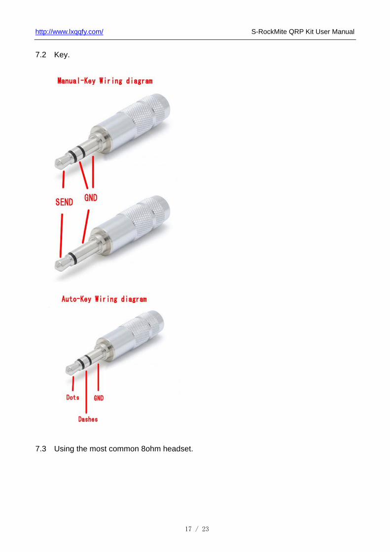
7.2 Key.
7.3 Using the most common 8ohm headset.
17 / 23

http://www.lxqqfy.com/ S-RockMite QRP Kit User Manual
7.4 The antenna is the key of the shortwave station, Requirements: frequency 7MHz,
impedance 50ohm, SWR <1.5. Recommend the following:
7.3.1 GP Antenna.
Red: Radio; Bule: Feeder(50ohm); Violet: Fishing rod(9 meters); Yellow: Dummy grounds(9
meters); Pink:: Oscillator(10.1 meters);
18 / 23

http://www.lxqqfy.com/ S-RockMite QRP Kit User Manual
7.3.1 Windom Antenna.
Winton antenna can be good to work in the three 40m/20m/10m band, the use of 1:4
Balun, according to the actual environment can have a variety of different installation
methods.
19 / 23

http://www.lxqqfy.com/ S-RockMite QRP Kit User Manual
7.3.1 DP Antenna.
The DP antenna is adopted skywave communication,long distance communication
effect is very good,the use to 1:1 balun, usually V installation.
20 / 23

http://www.lxqqfy.com/ S-RockMite QRP Kit User Manual
7.4 The use of WIFI Module and Mobile phone APP
7.4.1 Download Mobile phone APP from http://www.lxqqfy.com/.
7.4.2 Install WIFI module, circuit breaker JP1,power on.
7.4.3 Open Mobile phone, connect WIFI,The name is " LXQQFY********",the password is
"********","********" is 8 bit random number.
7.4.4 Open the APP,will be prompted to connect successfully. The status bar at the bottom
of the screen will display the current state of the connection.
7.4.5 Run windows.
7.4.5.1 The information is displayed on the top of the blue bar, connection status is
displayed in the bottom of the blue bar.
7.4.5.2 The second row: the Sending timming; The third row: the Morse code; The fourth
row: Identified words;
7.4.5.3 "Manual Key":Send control; "F1" and "F2":Automatically send F1 and F2 code; "to
Config Window":Switch to Config Window;
21 / 23

http://www.lxqqfy.com/ S-RockMite QRP Kit User Manual
7.4.6 Config Window.
7.4.6.1 "Send speed ":The time unit of send, the time unit is also identified.
7.4.6.2 "Update": The current information send to the radio; "Read": The current
information read from the radio; "Save": The current information save to Mobile phone;
"Recover": The current information recover from Mobile phone;
22 / 23

http://www.lxqqfy.com/ S-RockMite QRP Kit User Manual
23 / 23
8 List of components
1/4W Resistor Capacitor R1 0 ohm C1 C2 C3 C4 C5 C6 C7 C8 0.1uF(104)
R25 R26 10 ohm C18 C19 C20 C21 C22 C23 C24 C25 10nF(103)
R2 R3 22ohm/1W C17 1nF (102)
R27 100 ohm C15 C16 100pF(101)R18 200 ohm C9 C10 33pF(33)
R5 R7 1K C27 C26 56pF (56) R23 2K2 C13 C11 C14 C12 470pF(471)
R11 R12 10K Electrolytic capacitor R29 R30 R32 R31 R33 R34
R35 R28 4K7 CP1 CP2 CP3 1000uF/16V
R19 R20 22K CP4 CP5 CP6 CP7 100uF/25V R14 R15 47K CP8 CP9 10uF/16V
R24 100K CP10 1uF/16V R16 R17 220K Inductance R21 R22 470K T1 1:4 transformer (FT37-43 6)
Transistor T2 Transformer(FT37-43 8:2) D1 2W10(Bridge rectifier) L1 L2 1uH(T37-2 16) D2 1N4755A(Diode) IC D7 1N4001(Diode) U1 78L06
D3 D4 D5 D6 D8 1N4148(Diode) U2 NE602 Q8 2N7000(FET) U3 NE5532 Q1 9018(Triode) Crystal oscillator
Q2 D882(Triode) Y1 Y2 Y3 7.023MHz
Q3 Q4 Q5 Q6 8050(Triode) Variable resistor Q7 8550(Triode) W1 47K(473)
LED Two color LED Other PCB * 1 JP1 Pin and Jumper Cap
0.5mm Enameled wire J1 Q9(BNC) The heat sink and screw (for D882) J2 DC Jack
51ohm 2W Resistor(for dummy load) J3 J4 3.5mm Socket(Key and Phone)Acrylic case S1 S2 Key
SIP5 DIP6(for WIFI Module) WIFI Module(Optional)


1 2 3 4 5 6
A
B
C
D
654321
D
C
B
A
Q78550
R284K7
C1810nF
R24
100K
D71N4001
Y1
7.023MHz
R1447K
BB CC
EE
Q19018
C26
56pF
R1922K
R51K
CLKR27
100
C2756pF
C15
100pF
C1910nF
R1547K
Q38050
VCC_12V
T2
8:2
R10
C20
10nF
CP4100uF/16V
C2110nF
D31N4148
Q2D882
T1
FT37-43
D21N4755A
C2
0.1uF C11470pF
L1
1uH/T37-2C17
1nF
L2
1uH/T37-2
C16
100pF
C12470pF
R222/1W
Q48050
C30.1uFR29
4K7
C10
33pF
D51N4148
D61N4148
Y3
7.023MHz
Y2
7.023MHzC933pF
Vin1
GN
D2
Vout 3U1
78L06
VCC_12V
CP5100uF/16V CP6
100uF/16VC40.1uF
INA
INB
GND
OUTA OUTB
OSCB
OSCE
VCC
U2
NE602
C5
0.1uF
C22
10nF C2310nF
C60.1uF
CLK
C2410nFC7
0.1uF
R11
10KR12
10K
R21470K
5
67
84
U3B
NE5532
CP810uF/16V
R232K2
R2022K
R22
470KC13470pF
C25
10nF
3
21
84
U3A
NE5532
R3
22/1W
CP7
100uF/16V
R17
220KC1410nF
CP9
10uF/16V J3
PHONE
R71K
C80.1uF
VCC
R304K7
VCC_12V
D41N4148
Q68050R31
4K7
R32
4K7VCC_12V
J4
KEY
J2
CP11000uF/16V C1
0.1uF
VCC_12V
CP21000uF/16V
1 2
JP1
1
2
3
4
D1
S1
WIFI
R25
10
R26
10
CP31000uF/16V
GND1 12V2
DASH 7
DOT 8
A1 9
A2 10
A3 11
CONFIG3 RXD4 TXD5 CTRLOUT 6CW1
CWWIFI
S2
F1
R33
4K7
R34
4K7
VCC
R35
4K7
BB
CC E E
Q58050
LEDA
LEDB
VCC VCC_12V
VCC
VCC
R16220K
G1 D2
S3
Q82N7000
CP1016V/1uF
D8
1N4148
R18
200
11
33
W 2
W1
47K
J1ANT