Embed Size (px)
Citation preview

SENIOR
THESIS TECHNICAL REPORT 1: EXISTING CONDITIONS
Jacob Wiest || Structural Option
Faculty Advisor: Dr. Andrés Lepage
Date Submitted: September 23rd, 2011

Jacob Wiest || Structural [TECHNICAL REPORT 1: EXISTING CONDITIONS]
2 | P a g e
September 23rd, 2011 Judicial Center Annex || Rockville, MD
Table of Contents Executive Summary ...................................................................................................................................... 3
Building Introduction ................................................................................................................................... 4
Structural Overview ..................................................................................................................................... 5
Foundations .............................................................................................................................................. 5
Floor Systems ............................................................................................................................................ 6
Framing System ......................................................................................................................................... 7
Lateral System ........................................................................................................................................... 7
Roof System .............................................................................................................................................. 8
Design Codes ............................................................................................................................................. 8
Materials Used .......................................................................................................................................... 9
Gravity Loads .............................................................................................................................................. 10
Dead and Live Loads ................................................................................................................................ 10
Snow Loads ............................................................................................................................................. 11
Gravity Checks ......................................................................................................................................... 12
Column D4 .......................................................................................................................................... 12
PT Slab ................................................................................................................................................. 12
Doubly Reinforced Beam .................................................................................................................... 13
Lateral Loads ............................................................................................................................................... 14
Wind Loads .............................................................................................................................................. 14
Seismic Loads .......................................................................................................................................... 18
Conclusion .................................................................................................................................................. 20
Appendices ................................................................................................................................................. 21
Appendix A: Snow Load .......................................................................................................................... 21
Appendix B: Wind Load ........................................................................................................................... 22
Appendix C: Seismic Load ....................................................................................................................... 24
Appendix D: Gravity Check, Column ...................................................................................................... 25
Appendix E: Gravity Check, Slab ............................................................................................................. 27
Appendix F: Gravity Check, Beam ...................................................................................................... 3333

Jacob Wiest || Structural [TECHNICAL REPORT 1: EXISTING CONDITIONS]
3 | P a g e
September 23rd, 2011 Judicial Center Annex || Rockville, MD
Executive Summary
The objective of Technical Report 1 is to gain an understanding of the Judicial Center Annex
through investigation of its existing conditions. The structural system will be summarized with
calculations performed to obtain both gravity and lateral loads. Any loads presented on the
drawings are used as a point of reference to validate any assumptions made. The pertinent
design codes are summarized in addition to the materials to be used in the construction of the
building.
The gravity loads are further verified by three spot checks performed on an interior column, a
post tensioned slab panel and a doubly reinforced beam to provide a range of the concrete
members involved in the building’s structural system.
Lateral load calculations performed in accordance with ASCE 7-05 to come up with initial values
for both wind and seismic loading. The seismic load was found to be with 10% of the base shear
presented on the structural drawings and to control by a factor of 2 over wind. Further lateral
analysis will be performed in Technical Report 3.
This report includes a variety of figures and hand calculations to reinforce points and support
any results that are spoken of during the course of the paper.
Jacob Wiest || Structural [TECHNICAL REPORT 1: EXISTING CONDITIONS]
4 | P a g e
September 23rd, 2011 Judicial Center Annex || Rockville, MD
Building Introduction
The Judicial Center Annex (JCA) is a modern
addition to the existing Montgomery County
Judicial Center. Located on the corners of Maryland
Avenue and East Jefferson Street in downtown
Rockville, MD the JCA is set provide a bold
statement through both its architecture and
engineering. Construction on the addition began
this past April and is projected to take two years to
complete.
The JCA will stand 114’ tall at the crest of each of
the four lanterns located on top of the building, so
tall that local building codes needed waved for overall building height. Six stories rise above the
ground, with garage and terrace levels located below grade, adding approximately 210,000 sq ft
to the Judicial Center that will add 10 more courtrooms and administrative spaces among other
spaces.
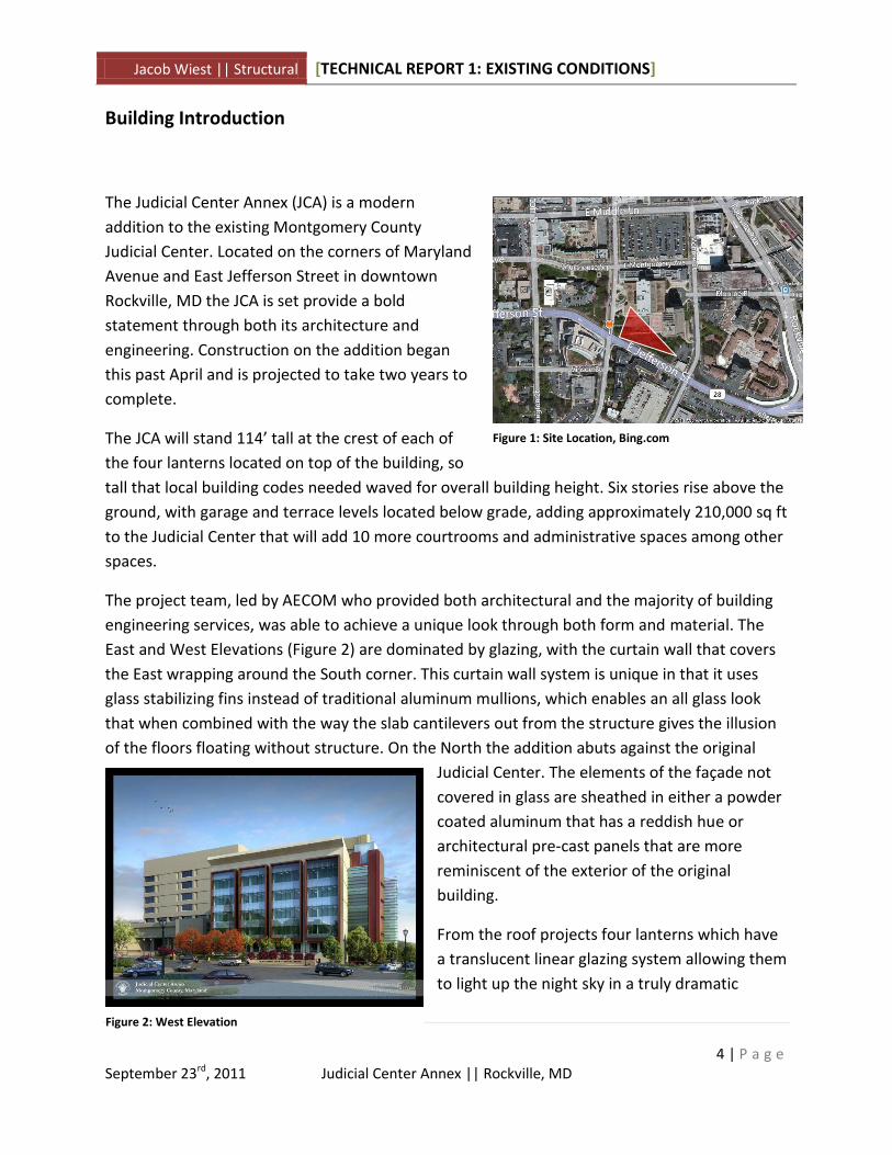
The project team, led by AECOM who provided both architectural and the majority of building
engineering services, was able to achieve a unique look through both form and material. The
East and West Elevations (Figure 2) are dominated by glazing, with the curtain wall that covers
the East wrapping around the South corner. This curtain wall system is unique in that it uses
glass stabilizing fins instead of traditional aluminum mullions, which enables an all glass look
that when combined with the way the slab cantilevers out from the structure gives the illusion
of the floors floating without structure. On the North the addition abuts against the original
Judicial Center. The elements of the façade not
covered in glass are sheathed in either a powder
coated aluminum that has a reddish hue or
architectural pre-cast panels that are more
reminiscent of the exterior of the original
building.
From the roof projects four lanterns which have
a translucent linear glazing system allowing them
to light up the night sky in a truly dramatic
Figure 1: Site Location, Bing.com
Figure 2: West Elevation

Jacob Wiest || Structural [TECHNICAL REPORT 1: EXISTING CONDITIONS]
5 | P a g e
September 23rd, 2011 Judicial Center Annex || Rockville, MD
manner. The roof is also the site of two of the JCA’s sustainable features that enabled it to
achieve a LEED Gold Rating. The tops of each of the four lanterns are covered in photovoltaic
panels, while green roofs cover much of the remaining roof.
Structural Overview
The JCA sits atop core-drilled concrete piers due to the rather poor soil conditions, all columns
coming to bear atop a pier. The floor systems are post-tensioned slabs, with wide-shallow
beams running one-way on the typical levels framing into cast-in-place concrete columns. The
lateral system consists of five concrete shear walls, which rise continuously to the penthouse
level, with some continuing to support the roof.
This building was designed as Occupancy III according to Sheet 1.S001. The reason for this is
thought that the holding cells in the building subject it to the “Jail and detention facilities”
clause or perhaps a courtroom has the ability for “more than 300 people to congregate.” This
Occupancy was assumed due to one of the previously mentioned reasons for purposes of
coming up with importance factors in later calculations.
Foundations
Schnabel Engineering performed the geotechnical services on
the JCA project. Reports indicated that for the purposes of
shallow continuous wall footings the soil has a bearing capacity
of 2000 psi, with any unsuitable conditions requiring excavation
and replacement with lean concrete. Core-drilled piers ranging
in diameter from 2.5’ to 7’ are located beneath every column
and support much of the shallow wall footings. Grade beams are
also used in several locations, specifically beneath the five shear
walls. Using Grade beams beneath the shear walls, which not
only have a larger self-weight as they rise continuously for most
of the building height, but they will also exert additional
compressive forces to into the foundations as they transfer the
lateral loads of the building into the soil. In addition, typing into the Grade beams would help
against uplift which will be investigated further in Technical Report 3. Grade beams vary from
24” to 42” in width and 36” to 72” in depth. The SOG is 5” thick and reinforced with WWF.
The garage level of the JCA is located 25’ below grade. Though soil pressures on basement walls
were not considered in this report they are a possible point of investigation in the future.
Figure 3: Column adjacent to existing Judicial Center resting on pier foundation

Jacob Wiest || Structural [TECHNICAL REPORT 1: EXISTING CONDITIONS]
6 | P a g e
September 23rd, 2011 Judicial Center Annex || Rockville, MD
Floor Systems
As mentioned previously, the floor systems for the JCA utilize post-tensioning. The economy is
achieved by greater span lengths being possible, with smaller slab depths. The typical floor
system, which begins on the terrace level and extends to the 5th floor has both 8” and 9” slab
depths, with wide-shallow beams running in the plan NS direction. These are denoted as
continuous drop panels on the drawings and extend an additional 8” beneath the slab, with
average width of 8’ that is not centered on the column lines. The beams are skewed towards
the larger spans, which gives the idea that the added stiffness the beams provide allow for
these slab depths to be achieved. In the slab gravity check which will be discussed later, ln/45, a
typical slab span-to-depth ratio was not achieved for the longest spans of approximately 41’. It
is here that it is thought the shallow beams are especially advantageous. The term continuous
drop panel is thought to be utilized as the beams provided additional negative moment
resistance around the columns. The bays are essentially uniform in parts of the building, with
an alternating long/short/long span pattern. A small portion of the slab on the second level
connecting to the existing building is lightweight concrete on metal deck on steel framing.
The penthouse slab is 11” thick due to the larger loads present on this floor. There is an
unreducible 150 psf mechanical live load present, as well as a 55 psf green roof dead load in
several areas. The mechanical floor also features a floating four inch light weight concrete on
metal deck isolation slab, to prevent mechanical equipment vibrations from affecting other
parts of the building. The roof slab is 10” and features several large voids. This slab has post
tensioned beams 36” x 24” typical for additional span stiffness in lieu of the wide-shallow
beams.
Figure 4: Section of PT slab showing tendon drape

Jacob Wiest || Structural [TECHNICAL REPORT 1: EXISTING CONDITIONS]
7 | P a g e
September 23rd, 2011 Judicial Center Annex || Rockville, MD
Framing Systems
Cast-in-place columns rise from the garage level to the roof, with the four lanterns extending
the extra fourteen feet with steel framing. The column concrete has a compressive strength of
7000 psi at the base, which is reduced to 5000 psi at level 2. Typical column sizes are 24”x24”
Lateral System
The lateral system of the JCA is comprised of five cast-in-place concrete shear walls, see Figure
5. The shear walls in the NS plan direction extend to the roof, while in the EW direction they
reach the penthouse level. The walls extend continuously upward and feature large openings
relying on link beams to maintain the load path from the various floor heights to the
foundation. The walls are all 12” thick, and assuming a rigid diaphragm (reasonable for the thick
concrete slabs), the walls will take load in proportion to their stiffness. Based upon their similar
thicknesses, this stiffness will then be proportional to their length, meaning that in the EW
direction shear walls 4 and 5 each take half the lateral force, while in the NS direction shear
wall 1 takes half the load with shear walls 2 and 3 splitting the other half between them. These
assumptions will be investigated more in depth through the usage of computer software in
subsequent reports. Also worth investigation is how much of the load is transferred through
frame action in the concrete slab and columns, and whether overturning will be an issue for the
shear walls that are tied into grade beams.
Figure 5: Shear Wall Layout

Jacob Wiest || Structural [TECHNICAL REPORT 1: EXISTING CONDITIONS]
8 | P a g e
September 23rd, 2011 Judicial Center Annex || Rockville, MD
Roof Systems
The roof varies in height in several locations with the floor slabs described earlier in Floor
Systems. The varying heights made snow drift a concern, and the large loads associated with
the penthouse floor, which is the heaviest floor on the building, add a significant contribution
to both seismic base shear and overturning. The green roof and pavers on the penthouse and
upper roof levels lay overtop a hot applied fluid membrane.
Design Codes
The list of Major Codes and Standards on Sheet 1.S001 is as follows:
2009 International Building Code
ACI 318-08
AISC LRFD, 13th Edition, 2005
AWS D1.1, D1.3, D1.4, Current Edition
ASTM, Current Edition
Steel Deck Institute Design Manual for Composite Deck, Form Decks and Roof Decks.,
2007
These are the codes being used to complete the analyses performed in this report, with heavy
usage of ASCE 7-05 (Minimum Design Loads).
Jacob Wiest || Structural [TECHNICAL REPORT 1: EXISTING CONDITIONS]
9 | P a g e
September 23rd, 2011 Judicial Center Annex || Rockville, MD
Materials Used
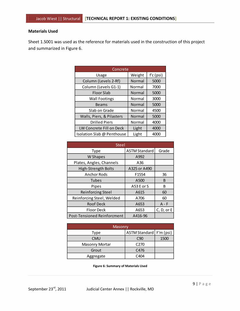
Sheet 1.S001 was used as the reference for materials used in the construction of this project
and summarized in Figure 6.
Figure 6: Summary of Materials Used
Usage Weight f'c (psi)
Column (Levels 2-Rf) Normal 5000
Column (Levels G1-1) Normal 7000
Floor Slab Normal 5000
Wall Footings Normal 3000
Beams Normal 5000
Slab on Grade Normal 4500
Walls, Piers, & Pilasters Normal 5000
Drilled Piers Normal 4000
LW Concrete Fill on Deck Light 4000
Isolation Slab @ Penthouse Light 4000
Concrete
Type ASTM Standard Grade
W Shapes A992
Plates, Angles, Channels A36
High-Strength Bolts A325 or A490
Anchor Rods F1554 36
Tubes A500 B
Pipes A53 E or S B
Reinforcing Steel A615 60
Reinforcing Steel, Welded A706 60
Roof Deck A653 A - F
Floor Deck A653 C, D, or E
Post-Tensioned Reinforcment A416-96
Steel
Type ASTM Standard F'm (psi)
CMU C90 1500
Masonry Mortar C270
Grout C476
Aggregate C404
Masonry

Jacob Wiest || Structural [TECHNICAL REPORT 1: EXISTING CONDITIONS]
10 | P a g e
September 23rd, 2011 Judicial Center Annex || Rockville, MD
Gravity Loads
This section will describe how dead, live, and snow loads were calculated and compared to
loadings given on the structural drawings. Three gravity checks were performed once the
loadings were determined for an interior column, the typical long span for the post tensioned
slab, and a doubly reinforced beam with full hand calculations available in Appendix A.
Dead and Live Loads
The dead loads listed on 1.S001 shown in
Figure 7 were used for the purposes of
analyses. The non-load-bearing CMU walls
were assumed to be fully grouted for the
purposes of worst-case load calculations. The
weight of the building was calculated
neglecting voids in slabs and with an
assumption of 10 psf for the steel lantern framing, which would not have much effect on the
building weight were it too small an assumption. The total building weight which was used for
the seismic calculations was in the order of 28000 kips.
Based upon ASCE 7-05 the 100 psf typical live load was found to be correct, possibly for
different reasons than the designer decided for, and the 40 psf holding cell load was neglected
in favor of using the 100 psf live load in all locations except for the mechanical penthouse and
the roof loading.
Design Student
Vegetated Roof 55 55
MEP/Celing 15 15
CMU Partitions Actual Weight
91 pcf (Fully
Grouted
Assumption)
Dead Loads
Figure 7: Summary of Dead Loads
Design ASCE 7-05
Typical 10080 (Corrider Above First Floor)
+ 20 (Partition) = 100
Holding Cells 40 -
Mechanical
Penthouse150 150
Roof - 20
Live Loads
Figure 8: Summary of Live Loads
Jacob Wiest || Structural [TECHNICAL REPORT 1: EXISTING CONDITIONS]
11 | P a g e
September 23rd, 2011 Judicial Center Annex || Rockville, MD
γ= 17.25
Lu Ll hc hd Lee hd Wind hd (ft) w (ft) Max psf
Drift 1 130 50 16 3.79826 1.764815 3.79826 3.79826 15.19 65.52
Drift 2 93 30.33 18 3.238561 1.321269 3.238561 3.238561 12.95 55.87
Drift 3 70 50 18 2.810406 1.764815 2.810406 2.810406 11.24 48.48
Drift 4 70 20 21 2.810406 1.004234 2.810406 2.810406 11.24 48.48
Drift 5 70 20 14 2.810406 1.004234 2.810406 2.810406 11.24 48.48
Drift 6 38 12 14 2.016252 0.670866 2.016252 2.016252 8.07 34.78
Drift 7 21 147 16 1.385528 3.014862 3.014862 3.014862 12.06 52.01
Drift 8 83 24 52 3.06224 1.137649 3.06224 3.06224 12.25 52.82
Snow Drift
Snow Loads
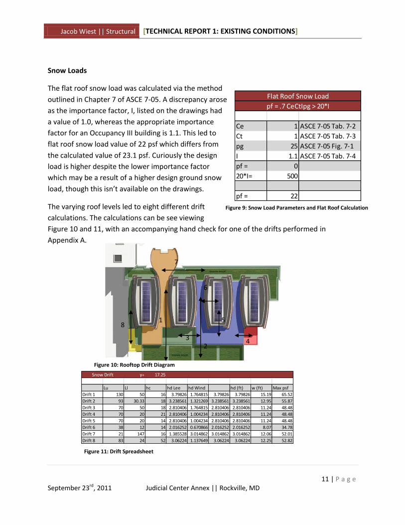
The flat roof snow load was calculated via the method
outlined in Chapter 7 of ASCE 7-05. A discrepancy arose
as the importance factor, I, listed on the drawings had
a value of 1.0, whereas the appropriate importance
factor for an Occupancy III building is 1.1. This led to
flat roof snow load value of 22 psf which differs from
the calculated value of 23.1 psf. Curiously the design
load is higher despite the lower importance factor
which may be a result of a higher design ground snow
load, though this isn’t available on the drawings.
The varying roof levels led to eight different drift
calculations. The calculations can be see viewing
Figure 10 and 11, with an accompanying hand check for one of the drifts performed in
Appendix A.
Ce 1 ASCE 7-05 Tab. 7-2
Ct 1 ASCE 7-05 Tab. 7-3
pg 25 ASCE 7-05 Fig. 7-1
I 1.1 ASCE 7-05 Tab. 7-4
pf = 0
20*I= 500
pf = 22
Flat Roof Snow Load
pf = .7 CeCtIpg > 20*I
Figure 9: Snow Load Parameters and Flat Roof Calculation
Figure 11: Drift Spreadsheet
1
2 3 4
1
5
6
7
8
Figure 10: Rooftop Drift Diagram

Jacob Wiest || Structural [TECHNICAL REPORT 1: EXISTING CONDITIONS]
12 | P a g e
September 23rd, 2011 Judicial Center Annex || Rockville, MD
Gravity Checks
Column D4 Gravity Check
Column D4 is an interior column located in one of the more typical bays. The 24”x24” column
extends the entire height of the building and was checked for strength considerations at the
base where it has (8) #10 vertical bars and #3 ties at 16” on center. The column was cast with
7000 psi concrete at this level; though at level two it transitions to 5000 psi concrete and (8) #8
vertical bars. Loads were summed for each level and the column was assumed to be in a state
of pure compression as it is in an interior column that is not intended to act as part of the
lateral system.
The column’s capacity was found to be more than adequate. It was
calculated that it could carry approximately 2240 kips in a state of
pure compression, while only having a demand of 1330 kips. It’s
possible that this means the assumption of pure compression was
a poor one and that the column indeed sees moment through
either the uneven spans or some incidental lateral load. The
possibility of lateral load will be addressed in a later report when
the system is explicitly modeled with computer software and
lateral force distribution can be seen, see Appendix D for hand
calculations.
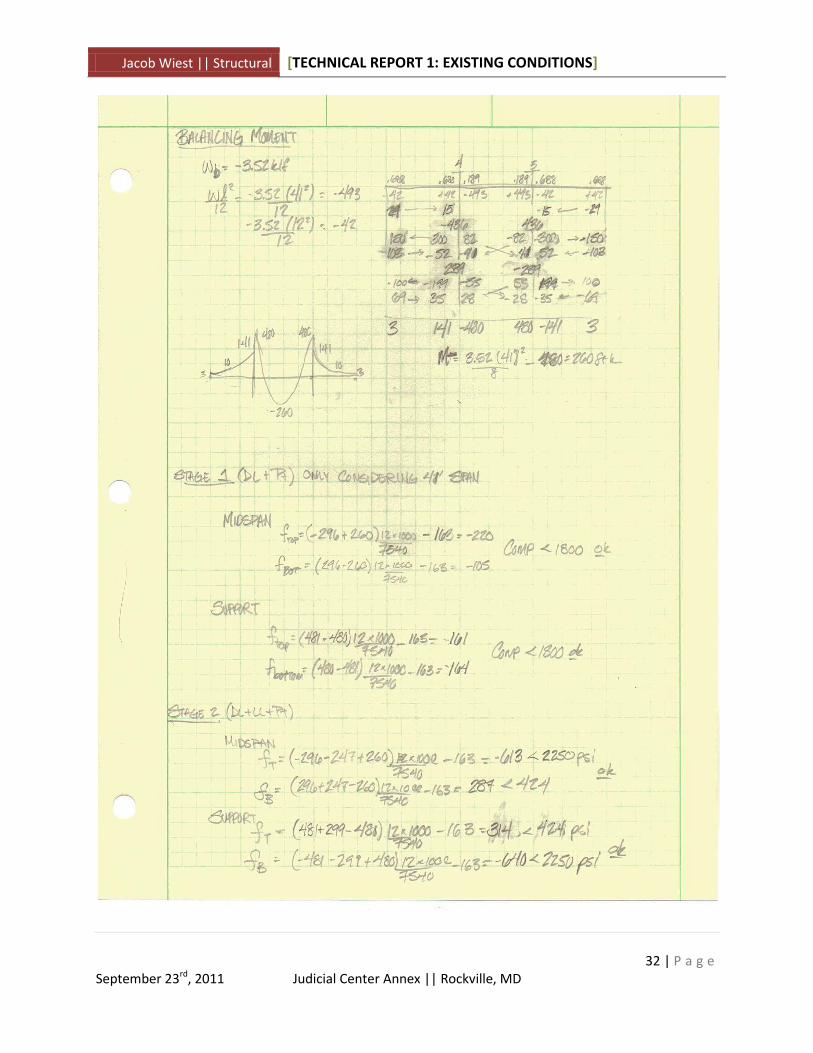
Post Tensioned Slab Check
To investigate the post tensioned slab a Frame along line E was chosen. This represented a
portion of the building with the most uniform bays, albeit with a long/short/long span pattern,
and also the portion that had the largest spans and so would likely be the controlling factor in
design of certain aspects.
The Equivalent Frame method was employed, as required by ACI 318-08 Chapter 18. In an
effort to simplify the procedure dimensions were made uniform for the various spans, though
only one bay was considered, and beams were centered on column lines. The first discrepancy
came in the calculation of a proper slab depth given the span using h = ln/45. This resulted in a
slab having to be 10 ½“ to have a span to depth ratio where deflection would not be considered
an issue. This was greater than the designed 9”, though it has been heard of for a ratio of ln/50
to be used which gives a value of 9 ½”. The thought is the wide-shallow beams allow the
thinner slab thickness.
Figure 12: Column D4

Jacob Wiest || Structural [TECHNICAL REPORT 1: EXISTING CONDITIONS]
13 | P a g e
September 23rd, 2011 Judicial Center Annex || Rockville, MD
The analysis was carried out; finding the jacking force, P, to be equal to 583 kips. This seems
consistent with the given jacking forces of 648 kips. The original jacking force was found to be
600 kips but was lowered as it over balanced the dead load, but the results are close enough to
consider consistent. The number of tendons needed was found to be 24, though this number
could not be found in the drawings. Drape values were almost identical between what were
used in the hand calculations and what appear on the drawings. See Appendix E.
Doubly Reinforced Beam Check
The final gravity spot check was performed on one of the few non-post tensioned beams to
explore the different systems employed within the structure. Beam B5 was chosen, an exterior
beam on the plan North side of the building that appears in levels 1-5. A non-load-bearing CMU
wall sits atop the beam and two point loads can be seen to act on the beam due to the pre-cast
façade being attached at these points.
The beam is 16”x24” with (3) #6’s top and bottom in the
center of the span. A simply supported condition was
assumed as no end bars were present in the beam schedule.
The beam has an approximate span of 9.67’, and the 18 kip
point load was assumed to act 1’ from the support as no
dimension could be seen.
Assuming Case 2, where the bottom steel is yielding but the
top is not, resulted in a moment capacity of 423 k-ft, far
greater than the required 60 k-ft. Only flexure was considered, with the apparent overdesign
possible as a result of either shear or torsion, but with a point load so close to the critical
section shear is a good possibility and could be examined in subsequent reports. See Appendix
F.
Figure 13: PT Slab Frame
Figure 14: Beam Location

Jacob Wiest || Structural [TECHNICAL REPORT 1: EXISTING CONDITIONS]
14 | P a g e
September 23rd, 2011 Judicial Center Annex || Rockville, MD
Lateral Loads
Wind (Appendix B) and seismic (Appendix C) loads were calculated using prescribed methods
from ASCE 7-05. These preliminary hand calculations give some insight into the behavior of the
building and the controlling factors, which will be further explored in Technical Report 3.
Wind Loads
Method 2 Main Wind Force Resisting System (MWRFS) procedure from ASCE 7-05 chapter 6
was used in the calculation of the wind forces the building will be subjected to. To simplify the
calculations, the maximum roof height was assumed to be 100’, though the lanterns extend to
114’. This is likely a good assumption on the grounds the lanterns themselves represent a small
surface area which wind load can be applied to in addition to making calculations simpler.
Additionally the floor plan was assumed rectangular and an idealized building width and length
were determined to get values of L and B.
Calculations were performed with the aid of Microsoft Excel, with a hand check of both the
velocity pressure and design wind pressure. The base shear in the NS direction was found to be
290 k and the EW direction had a base shear of 280 kips. As no wind pressures were listed to
compare to, these values are assumed accurate.
The components and cladding wind pressures were not considered in this report but would
need to be looked at going forward in the analysis as the wind loads are transferred through
the cladding into the floor slabs and into the shear walls before being transferred to the
foundations.

Jacob Wiest || Structural [TECHNICAL REPORT 1: EXISTING CONDITIONS]
15 | P a g e
September 23rd, 2011 Judicial Center Annex || Rockville, MD
Figure 15: Design Wind Pressures
(+) Gcpi (-) Gcpi (+) Gcpi (-) Gcpi
1st 0 7.86 3.61 -3.61 4.24 11.47
2nd 14 7.86 3.61 -3.61 4.24 11.47
3rd 29.5 9.59 3.61 -3.61 5.98 13.21
4th 46 10.89 3.61 -3.61 7.28 14.50
5th 62.5 11.85 3.61 -3.61 8.24 15.47
Penthouse 79 12.76 3.61 -3.61 9.15 16.38
Roof 100 13.65 3.61 -3.61 10.03 17.26
Leeward All - -8.53 3.61 -3.61 -12.14 -4.92
Side Walls All - -11.94 3.61 -3.61 -15.55 -8.33
0 - 50 -17.74 3.61 -3.61 -21.35 -14.13
> 50 -14.19 3.61 -3.61 -17.80 -10.58
Windward
Roof
Distance Wind PressureInternal Pressure Net Pressure
Design Wind Pressure N/S
(+) Gcpi (-) Gcpi (+) Gcpi (-) Gcpi
1st 0 7.86 3.61 -3.61 4.24 11.47
2nd 14 7.86 3.61 -3.61 4.24 11.47
3rd 29.5 9.59 3.61 -3.61 5.98 13.21
4th 46 10.89 3.61 -3.61 7.28 14.50
5th 62.5 11.85 3.61 -3.61 8.24 15.47
Penthouse 79 12.76 3.61 -3.61 9.15 16.38
Roof 100 13.65 3.61 -3.61 10.03 17.26
Leeward All - -7.85 3.61 -3.61 -11.46 -4.23
Side Walls All - -11.94 3.61 -3.61 -15.55 -8.33
0 - 50 -16.17 3.61 -3.61 -19.78 -12.56
> 50 -14.94 3.61 -3.61 -18.55 -11.33
Wind Pressure
Windward
Roof
Internal Pressure Net Pressure
Design Wind Pressure E/W
Distance

Jacob Wiest || Structural [TECHNICAL REPORT 1: EXISTING CONDITIONS]
16 | P a g e
September 23rd, 2011 Judicial Center Annex || Rockville, MD
Figure 16: Design Wind Forces
Height Ht Area Ht Area
1st 0 0 0 7 1050.00 17.20 290.26 0.00
2nd 14 7 1050 7.75 1162.50 36.25 273.05 507.52
3rd 15.5 7.75 1162.5 8.25 1237.50 43.49 236.80 1283.00
4th 16.5 8.25 1237.5 8.25 1237.50 48.06 193.31 2210.64
5th 16.5 8.25 1237.5 8.25 1237.50 50.45 145.25 3152.83
Penthouse 16.5 8.25 1237.5 10.5 1575.00 59.88 94.81 4730.73
Roof 21 10.5 1575 0 0.00 34.92 34.92 3492.37
290.26
15377.09Total Overturning Moment (k-ft)
Trib Above
Wind Force (NS)
Base Shear (k)
Trib Below Story
Force
Story
Shear
Overturning
Moment
Trib Above
Height Ht Area Ht Area
1st 0 0 0 7 1050.00 16.49 280.02 0.00
2nd 14 7 1050 7.75 1162.50 34.74 263.53 486.39
3rd 15.5 7.75 1162.5 8.25 1237.50 41.85 228.79 1234.70
4th 16.5 8.25 1237.5 8.25 1237.50 46.37 186.94 2132.96
5th 16.5 8.25 1237.5 8.25 1237.50 48.76 140.57 3047.29
Penthouse 16.5 8.25 1237.5 10.5 1575.00 57.96 91.81 4579.14
Roof 21 10.5 1575 0 0.00 33.85 33.85 3384.91
280.02
15145.41
Base Shear (k)
Total Overturning Moment (k-ft)
Trib Below
Wind Force (EW)
Story
Force
Story
Shear
Overturning
Moment

Jacob Wiest || Structural [TECHNICAL REPORT 1: EXISTING CONDITIONS]
17 | P a g e
September 23rd, 2011 Judicial Center Annex || Rockville, MD
Figure 17: N/S Wind Pressure and Wind Force Diagrams

Jacob Wiest || Structural [TECHNICAL REPORT 1: EXISTING CONDITIONS]
18 | P a g e
September 23rd, 2011 Judicial Center Annex || Rockville, MD
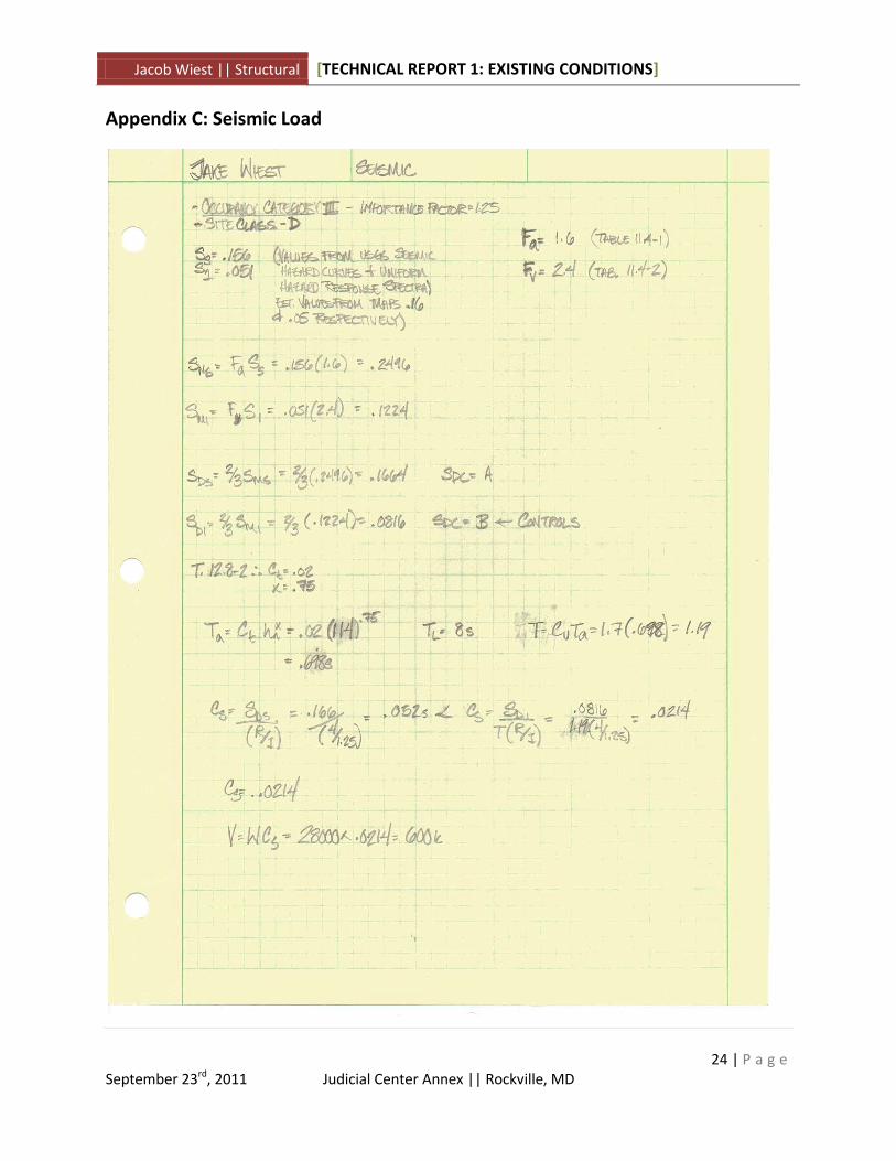
Seismic Loads
The seismic loads were calculated based upon the Equivalent Lateral Force Method outlined in
ASCE 7-05 Chapters 11 and 12. The fundamental period was calculated via equation 12.8-7 in
ASCE 7-05 and modified by the Cu coefficient found in Table 12.8-1 as the low base shear listed
on the drawings did not seem achievable given the weight of the structure if the period was
calculated via the method for shear walls. The full height of the building was also used which
resulted in a base shear of 600 kips, within 10% of the 560 kips listed on the drawings lending
weight to the earlier assumptions.
The seismic is seen to control by a factor of 2 over wind in this case, which may be the reason
why only the seismic base shear is shown on the structural drawings. The inertial response of
the building will be directly related to the mass, which means the majority of the seismic forces
originate in the slabs which transfer the forces directly to the shear walls.
Figure 18: Seismic Forces
LevelStory Ht
(ft)
Story
Weight (k)Cvx
Story
Force (k)
Shear
Shear (k)
Overturning
Moment (k-ft)1 0 3584.8713 0 0 600.00 0.00
2 14 4024.472 0.04259 25.55 600.00 357.76
3 29.5 4108.9654 0.091818 55.09 574.45 1625.18
4 46 4132.2627 0.144067 86.44 519.36 3976.25
5 62.5 4121.3877 0.195177 117.11 432.91 7319.13
PentHouse 79 5698.8439 0.352365 211.42 315.81 16702.10
Roof 98 2466.4583 0.173983 104.39 104.39 10230.21
600.00
40210.63Total Overturning Moment (k-ft)
Base Shear (k)
Seismic Forces

Jacob Wiest || Structural [TECHNICAL REPORT 1: EXISTING CONDITIONS]
19 | P a g e
September 23rd, 2011 Judicial Center Annex || Rockville, MD
Figure 19: Seismic Force Diagram

Jacob Wiest || Structural [TECHNICAL REPORT 1: EXISTING CONDITIONS]
20 | P a g e
September 23rd, 2011 Judicial Center Annex || Rockville, MD
Conclusion
Technical Report 1 gave an overview of the existing conditions of the Judicial Center Annex’s
structure. Various structural elements, including the foundations and floor slabs were
summarized with the intent to give a good understanding of how the current structure is
intended to be built and act.
Gravity and lateral loads were also determined over the course of this report using both ASCE
7-05 and the structural drawings as resources. The dead, live, and snow loads were compiled
and compared to the loads used with positive results. The lateral loads, calculated through
methods outlined in ASCE 7-05 compared favorably to the numbers that were present on the
drawings.
Gravity checks were performed on three members; a column, slab panel, and beam. These
members were chosen as they represented a wide range of what is present in the JCA’s
structural system, and all three are different components. While the checks may have not
considered every option they in general showed that the members were designed
appropriately. The added challenge of the slab configuration combined with post-tensioning
made for an interesting analysis.
Seismic loads were found to control by a factor of 2, and were found within 10% of the base
shear reported on the structural drawings indicating the validity of the assumptions and
methods used. This report presented many valid points, answering questions about the design
and raising new ones to be investigated in further reports.

Jacob Wiest || Structural [TECHNICAL REPORT 1: EXISTING CONDITIONS]
21 | P a g e
September 23rd, 2011 Judicial Center Annex || Rockville, MD
Appendix A: Snow Load

Jacob Wiest || Structural [TECHNICAL REPORT 1: EXISTING CONDITIONS]
22 | P a g e
September 23rd, 2011 Judicial Center Annex || Rockville, MD
Appendix B: Wind Load

Jacob Wiest || Structural [TECHNICAL REPORT 1: EXISTING CONDITIONS]
23 | P a g e
September 23rd, 2011 Judicial Center Annex || Rockville, MD
Figure 20: Wind Design Criteria
Figure 21: Velocity Pressure Coefficients and Velocity Pressures
Gcpi 0.18 ASCE 7-05 Fig. 6-5
Exposure B ASCE 7-05 6.5.6.3
V 90 mph ASCE 7-05 Fig. 6-1C
I 1.15 ASCE 7-05 Tab 6-1
Kzt 1 ASCE 7-05 6.5.7.1
Kd 0.85 ASCE 7-05 Fig. 6-4
Wind Load Criteria
Height Kz qz
1st 0 0.570 11.55
2nd 14 0.570 11.55
3rd 29.5 0.696 14.11
4th 46 0.790 16.01
5th 62.5 0.860 17.43
Penthouse 79 0.926 18.77
Roof 100 0.990 20.07
Velocity Presssure Coefficients (Kz) and
Velocity Pressures (qz)
Jacob Wiest || Structural [TECHNICAL REPORT 1: EXISTING CONDITIONS]
24 | P a g e
September 23rd, 2011 Judicial Center Annex || Rockville, MD
Appendix C: Seismic Load

Jacob Wiest || Structural [TECHNICAL REPORT 1: EXISTING CONDITIONS]
25 | P a g e
September 23rd, 2011 Judicial Center Annex || Rockville, MD
Appendix D: Gravity Check, Column

Jacob Wiest || Structural [TECHNICAL REPORT 1: EXISTING CONDITIONS]
26 | P a g e
September 23rd, 2011 Judicial Center Annex || Rockville, MD

Jacob Wiest || Structural [TECHNICAL REPORT 1: EXISTING CONDITIONS]
27 | P a g e
September 23rd, 2011 Judicial Center Annex || Rockville, MD
Appendix E: Gravity Check, Slab

Jacob Wiest || Structural [TECHNICAL REPORT 1: EXISTING CONDITIONS]
28 | P a g e
September 23rd, 2011 Judicial Center Annex || Rockville, MD

Jacob Wiest || Structural [TECHNICAL REPORT 1: EXISTING CONDITIONS]
29 | P a g e
September 23rd, 2011 Judicial Center Annex || Rockville, MD

Jacob Wiest || Structural [TECHNICAL REPORT 1: EXISTING CONDITIONS]
30 | P a g e
September 23rd, 2011 Judicial Center Annex || Rockville, MD

Jacob Wiest || Structural [TECHNICAL REPORT 1: EXISTING CONDITIONS]
31 | P a g e
September 23rd, 2011 Judicial Center Annex || Rockville, MD
Jacob Wiest || Structural [TECHNICAL REPORT 1: EXISTING CONDITIONS]
32 | P a g e
September 23rd, 2011 Judicial Center Annex || Rockville, MD

Jacob Wiest || Structural [TECHNICAL REPORT 1: EXISTING CONDITIONS]
33 | P a g e
September 23rd, 2011 Judicial Center Annex || Rockville, MD
Appendix F: Gravity Check, Beam

Jacob Wiest || Structural [TECHNICAL REPORT 1: EXISTING CONDITIONS]
34 | P a g e
September 23rd, 2011 Judicial Center Annex || Rockville, MD