Embed Size (px)
Citation preview
S TEE L N T ERe HAN G E
Steel Interchange is an open forum for Modern Stee l Construction readers to exchange useful and practical professional ideas and information on all phases of steel building and bridge construction. Opinions and suggestions are welcome on any subject covered in this magazine. If you have a question or problem that your fellow readers might help you to solve, please forward it to Modern Steel Construction. At the same time, feel free to respond to any of the questions that you have read here. Please send them to:
Steel Interchange Modern Steel Construction
One East Wacker Dr., Suite 3100 Chicago, IL 60601-2001
Answers and/or questions should be typewritten and doublespaced. Submittals that have been prepared by word-processing are appreciated on computer diskette (either as a Word file or in ASCII format).
The opinions expressed in Steel Interchange do not necessarily represent an official position of the American Institute of Steel Construction, Inc. and have not been reviewed. It is recognized that the design of structures is within the scope and expertise of a competent licensed structural engineer, architect or other licensed professional for the application of principals to a particular structure.
Information on ordering AISC publications mentioned in this article can be obtained by calling AISC at 800/644-2400.
* * * * Questions and answers can now be e-mailedto:[email protected] * * * *
The following responses from previous Steel Interchange columns have been received:
The structural steel design manuals establish a minimum length of thread on structural bolts, referencing ANSI BIB.2.1. They also give a formula of 2D+l//' for bolts less than 6" in length, and 2D+l/2" for bolts longer than 6" long. What are the consequences if the bolts are fabricated with thread lengths less than this amount, but still capable of making up a proper connection? Is this grounds for rejecting the bolts? Why is this length the same regardless of what type of bolted connection (N, X, SC) is used? It would seem that the thread length values should differ depending on the type. Finally, the Specification for Structural Joints Using ASTM A325 or A490 Bolts states "The length of the bolts shall be such that the ends of the bolt will be flush with or outside the face of the nut when properly installed." With this added criteria, it would seem that the thread lengths could be shorter than those specified in the Table, because a single nut and washer is never greater than 2D in length.
The two formulae (2D+'/." and 2D+ '/2") are for A307 bolts, not A325 or A490. N, X, and SC are
terms that do not apply to A307 bolts. Thread lengths and their function are explained
in the Research Council on Structural Connections Specification for Structural Joints Using ASTM A325 or A490 Bolts. One feature of A325 and A490 bolts is that any given diameter has the same thread length regardless of bolt length, e.g: % x 3 and % x 5 both have a 1%" thread length. This is a control factor for the structural engineer or the fabricator/erector to match bolt lengths.
Adrian L. Sherrill Placentia, CA
Are there any references on allowable compressive stress (buckling stress) for large
diameter (120 ft.) steel tank wall when it is empty and subjected to external soil pressure?
A good approach to this problem can be found in £\Steel Plate Engineering Data, Volumes 1 & 2 published by the American Iron and Steel Institute in association with the Steel Plate Fabricators Association. This method is based on providing sufficiently rigid stiffening rings at the extents of the soil pressure and then calculating the number of buckling waves between these rings. Intermediate stiffeners are provided between the rings to resist the buckling action. This should take care of the buckling mode.
The circumferential stress in the shell alone, not including the stiffening rings, must also be checked and should not exceed the allowable working stress for the shell material in compression. I have generally used 15,000 psi allowable compressive stress for most mild steels. (AWWA D100 Welded Steel Tanks for Water Storage also recommends 15,000 psi allowable compressive stress).
William N. Pulyer, P.E. Watkins Engineers & Constructors Greenville, SC
What size mig wire is considered structurally acceptable or comparable to an E70XX specification? Is there a solid wire that is acceptable? With what gas? Can the penetration and weld properties be equivalent to arc welding with, say, an E701B rod?
The welding electrode size is irrelevant to the strength that the weld metal develops. A MIG
wire that is identified as ER70S-X or ER70C-X (where "X" is some number) will exhibit strength equal to an E70XX type electrode. For carbon and low alloy steel welding using gas metal arc (GMAW), aka MIG), flux cored (FCAW) and submerged arc (SAW) welding, the electrode designations contain a number that identifies the minimum tensile strength that the weld metal will
Modern Steel Construction / December 1997/ 9
S TEE L N T ERe HAN G E
develop. This number is the first number after the "ER", "E" or the "F" in the classifications for the respective processes. For example, an ER70S-6 GMA W electrode will exhibit a minimum tensile strength of 70 ksi, an E110T5-K4 FCAW electrode will exhibit a tensile strength of 110 ksi and an F8A4-EA2-A2 SAW electrode/flux combination will develop a tensile strength of 80 ksi.
This designation system originates in the American Welding Society A5 series of specifications which deal with welding and brazing con sumabIes. A summary of appropriate applications is found in AWS D1.1, Structural Welding Code Steel, Table 3.1.
Walter J. Sperko, P.E. Sperko Engineering via email
New Questions Listed below are questions that we would like
the readers to answer or discuss. If you have an answer or suggestion please send
it to the Steel Interchange Editor, Modern Steel Construction, One East Wacker Dr. , Suite 3100, Chicago, IL 60601-2001. Questions can also be sent via e-mail [email protected].
Questions and responses will be printed in future editions of Steel Interchange. Also, if you have a question or problem that readers might help solve, send these to the Steel Interchange Editor.
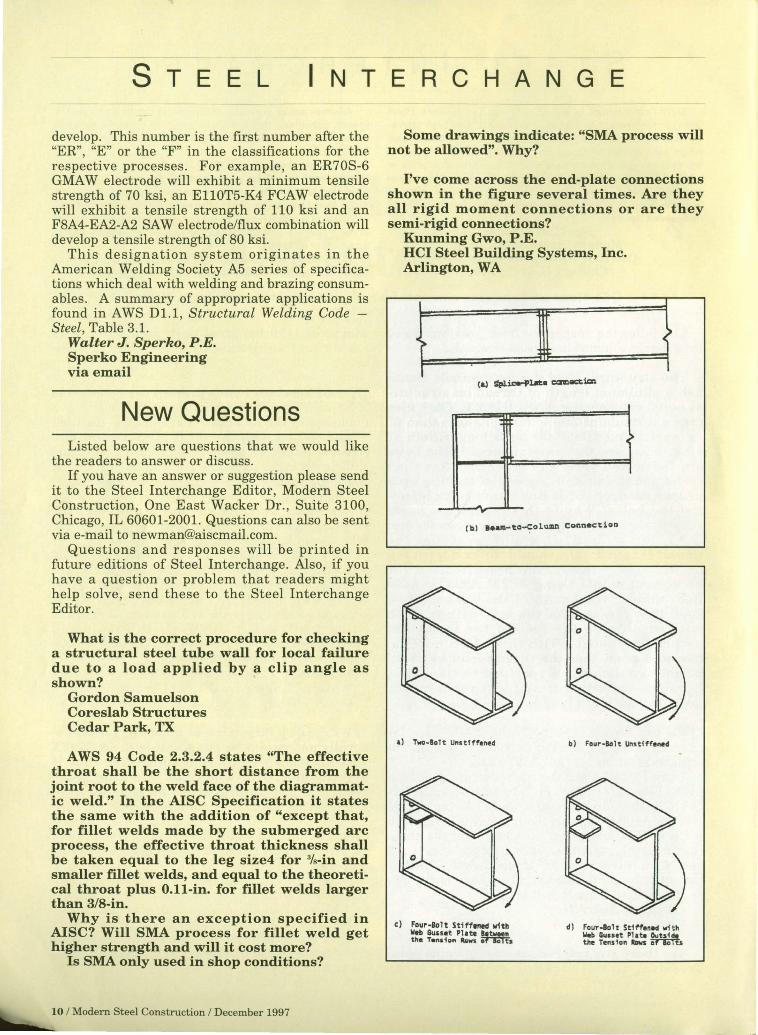
What is the correct procedure for checking a structural steel tube wall for local failure due to a load applied by a clip angle as shown?
Gordon Samuelson Coreslab Structures Cedar Park, TX
A WS 94 Code 2.3.2.4 states "The effective throat shall be the short distance from the joint root to the weld face of the diagrammatic weld." In the AISC Specification it states the same with the addition of "except that, for fillet welds made by the submerged arc process, the effective throat thickness shall be taken equal to the leg size4 for %-in and smaller fillet welds, and equal to the theoretical throat plus O.l1-in. for fillet welds larger than 3/8-in.
Why is there an exception specified in AISC? Will SMA process for fillet weld get higher strength and will it cost more?
Is SMA only used in shop conditions?
10 / Modern Steel Construction / December 1997
Some drawings indicate: "SMA process will not be allowed". Why?
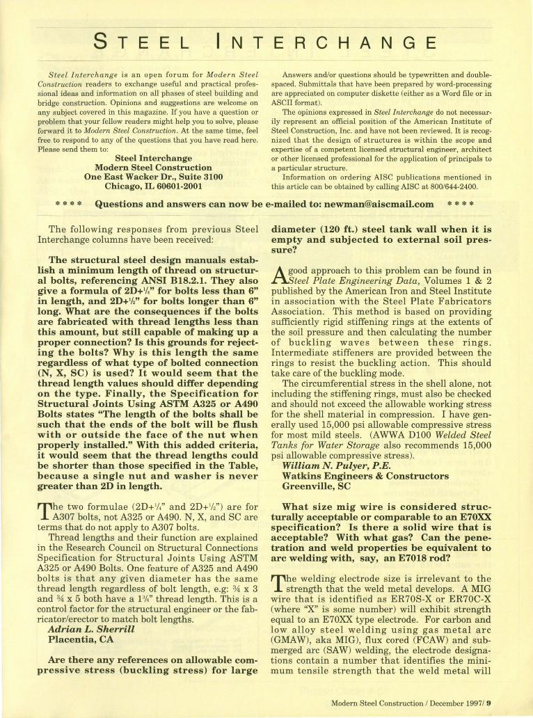
I've come across the end-plate connections shown in the figure several times. Are they all rigid moment connections or are they semi-rigid connections?
Kunming Gwo, P.E. HCI Steel Building Systems, Inc. Arlington, WA
~
(a.) ~ice-Plat:8 =-==
?
... (b) I •• M-~a-Cal~mn Connection
~ .5 I
.) T ... -801~ Un"Uff.".,d b) Four-Iolt Un.~fff.rH!d
d) Four-Bolt Stiffened ,.;th = ~~:~!/~ ~til".