Embed Size (px)
Citation preview
3679 S Huron Street, Suite 404 Englewood, Colorado 80110
Phone: (303) 789-4111 FAX: (303) 789-4310
S U B M I T T A L T R A N S M I T A L
July 25, 2012
WCM Submittal No: 11315-01.A PROJECT: Harold Thompson Regional WRF
Birdsall Rd. Fountain, CO 80817 Job No. 2908
ENGINEER: GMS, Inc. 611 No. Weber St., #300 Colorado Springs, CO 80903 719-475-2935 Roger Sams
OWNER: Lower Fountain Metropolitan Sewage Disposal District 901 S. Santa Fe Ave. Fountain, CO 80817 719-382-5303 James Heckman
CONTRACTOR: Seepex Inc. 511 Speedway Drive Enon, OH 45323 937-864-7150
SUBJECT: Progressive Cavity Pumps – SCP-1, SCP-2, DSP-1 & DSP-2 SPEC SECTION: 11315 – Progressive Cavity Pumps PREVIOUS SUBMISSION DATES: 6/26/12 DEVIATIONS FROM SPEC: YES X NO
CONTRACTOR’S STAMP: This submittal has been reviewed by Weaver Construction Management and,
unless indicated otherwise, has been found to be in conformance with the intent of the contract documents.
Contractor’s Stamp: Engineer’s Stamp: Date: 7/25/12 Reviewed by: John Jacob (X) Reviewed Without Comments ( ) Reviewed With Comments ENGINEER’S COMMENTS:_________________________________________________________________________________________________________________________________

Progressive Cavity Pump Re-Submittal
Supply of seepex, Inc. pumps & accessories: consisting of engineering drawings, descriptive literature, operating data and related information.
To:
Weaver Construction Management, Inc. 3679 S. Huron St.
Suite 404 Englewood, CO 80110-3498
Phone#: 303-789-4111, Fax#: 303-789-4310 Attn: Wesley Weaver, President
c/o:
Harold D. Thompson Water Reclamation Facility
Fountain, CO 80817
PO#: 9103
seepex Job#: 2113909
Specifications Section: PROGRESSING CAVITY PUMP
Equipment No: Denomination: Pump Type: Commission#’s: Tag#’s:
Digested Sludge BN 52-6L 832027-028 DSP-1 & 2 Scum BN 35-6L 832029-032 SCP-1 & 2
Represented Locally By:
Ambiente H2O Inc.
Wastewater & Water Treatment Specialists 1500 W. Hampden Ave.,
Suite 5D Sheridan, CO 80110
Phone #: 303-433-0364, Fax #: 303-380-0664 Attn: Brian Johnson, [email protected]
By: seepex, Inc.
511 Speedway Dr. Enon, OH 45323
Phone#: 937-864-7150, Fax#: 937-864-7157
July 2012
RE-SUBMITTAL
Page 1 of 119

PO#: 9103
seepex Job#: 2113909
Tabs Page #'s1
4-5
6-7
8-10
12-14
15
16
17-20
21
22
23-26
27
28-29
30
31
2
33-35
36
37
38-39
40
41-50
51-59
3
61-63
64
65
66-67
68-77
78-86
4
88-89
90-102
103-112
5
114-119
Pump Accessories
Nameplate
Mechanical Seal Arrangement
Anchor Bolts
Sectional Drawing
General Brochures
Nord Gear Reducer
Pump Technical Data:
Nord Gear Reducer
Parts Listing
Mechanical Seal Drawing
WEG Motor
Performance Data
Duktil Coating TSE-Dry Running Protection Device
General Data
Sections
Warranty CardPaint Specifications TNEMEC
Weaver Comments dated 6/26/2012seepex Response Letters dated 7/20/2012
GSM Comments dated 7/16/2012
Product group N
BN 52-6L Data Sheet CN#: 832027-028Dimensional DrawingCharacteristic CurveNPSH Curve
Proco Flex JointOver Pressure Protection
WEG Motor
Long Term Preservation Guidelines
BN 35-6L Data Sheet CN#: 832029-030Dimensional DrawingCharacteristic CurveNPSH Curve
Pump Technical Data:
Terms and Conditions
Table of Contents-Submittal
Weaver Constr-Englewood, CO-Ambiente H2O-Harold D Thompson Water Reclam Facility
Page 2 of 119

Tab 1 General Data
Page 3 of 119

Inc.
seepex Inc. 511 Speedway Drive Enon, OH 45323 Phone (937) 864-7150 Fax (937) 864-7157 [email protected] www.seepex.com
July 20, 2012 Brian Johnson Ambiente H2O Inc. 5385 County Rd. 572 La Veta,Co. 81055 Subject: Response Letter
Harold D. Thompson Regional Water Reclamation Facility (HDTRWRF) Lower Fountain Metropolitan Sewage Disposal District (LFMSDD) Submittal No. 11315-001
Progressing Cavity Pumps seepex Job# 2113909 Please find the following comments for submittal, per specification #11315 Progressive Cavity Pumps:
1. See below: a. Materials of construction for the cartridge seals on both pumps are in conformance with
the project specifications and are suitable for the product being conveyed. Alphanumeric designators will be indicated and explained in the revised datasheet.
b. ¾-inch drain connection is provided in the base plate as an NPT plug as noted in the drawings and in the datasheets.
2. Digested sludge pumps are designed for 0.1% to 3.0% solids rate, please dismiss typography error, datasheets will be revised.
3. Digested sludge pumps are designed to operate at a temperature range of 5°C to 23°C, please dismiss typography error, datasheets will be revised.
4. Comment acknowledged, no further action required on our part. 5. Scum pumps are designed for 0.1% to 3.0% solids rate, please dismiss typography error,
datasheets will be revised. 6. Pump motors for the scum pumps are designed to run on a full voltage, non-reversing starter
(FVNR), datasheets will be revised to specify this. 7. Variations due to back-pressure, pipe tolerances and flow parameters are taken into consideration
when performing our calculations. Please see attached performance curve that shows the scum pump running at 206 rpm instead of 209 rpm this is while taken the variations into account. We are confident the pump will meet the desired 94 gpm at 60Hz, datasheet has been amended to show this.
8. It is confirmed that the proposed discharge overpressure devices can be installed downstream as shown in the contract drawings. All isolator rings shall be 4” ANSI B16.5 150lbs RF as they are being incorporated in the piping just after the pump’s discharge flange, datasheet for the sludge pumps has been updated.
9. The pumps discharge expansion joint models have been indicated in the datasheets. They will be Proco brand FA-231 model. We will mark our current cut sheet to show what will be supplied.
10. Control panels are not included in the pump manufacturer’s scope of supply or pricing, no further action required on our part.
Regards, Hector Santiago Environmental Applications Engineer cc: Kevin Thomas (seepex)
Page 4 of 119

Inc.
seepex Inc. 511 Speedway Drive Enon, OH 45323 Phone (937) 864-7150 Fax (937) 864-7157 [email protected] www.seepex.com
July 20, 2012 Brian Johnson Ambiente H2O Inc. 5385 County Rd. 572 La Veta,Co. 81055 Subject: Response Letter
Harold D. Thompson Regional Water Reclamation Facility (HDTRWRF) Lower Fountain Metropolitan Sewage Disposal District (LFMSDD) Submittal No. 11315-001
Progressing Cavity Pumps seepex Job# 2113909 Please find the following comments for submittal, per specification #11315 Progressive Cavity Pumps:
1. We will acknowledge the terms and conditions agreed upon to in the Purchase Agreement. 2. Long-term preservation information will be provided and incorporated in the O&M manual. 3. Warranty card will be completed and provided in a separate O&M manual. 4. Please see attached revised datasheet for model and materials of construction. 5. Motors for digested sludge pumps are designed for an altitude of 5390 feet above sea level. 6. To achieve maximum nominal operating motor speeds of 900 rpm, the design should be changed
to an 8-pole motor design instead of a 4-pole design, please confirm. 7. BHP will not exceed 4.4 at any point in the operation range for digested sludge pumps. 8. Drain pan will be fabricated in stainless steel per 2.3.C.3. 9. We will provide an expansion joint/ reducer as a 5”X4” with a 6” length. 10. NPSHr calculations for seepex pumps have an 1.5 feet safety factor implemented into the
formula, twelve (12) feet will suffice as 13.5 feet minus 1.5 feet equals 12 feet. 11. Motors for scum pumps are designed for an altitude of 5390 feet above sea level. 12. To achieve maximum nominal operating motor speeds of 900 rpm, the design should be changed
to an 8-pole motor design instead of a 4-pole design, please confirm. 13. BHP will not exceed 6.7 at any point in the operation range for scum pumps. 14. Drain pan will be fabricated in stainless steel per 2.3.C.3. 15. We will provide a 4”X4” expansion joint with 6” in length 16. Minimum requirements for the scum pumps NPSHr is 8.5 feet which is less than the maximum
NPSHr of 12 feet indicated on Section 2.1.B.9. Regards, Hector Santiago Environmental Applications Engineer cc: Kevin Thomas (seepex)
Page 5 of 119

Project: HDTWRF Project
Location: Fountain, CO
Supplier: Seepex, Inc
Date: 6/26/12
Submittal 11315-01 Progressive Cavity Pumps SCP-1 and 2; DSP-1 and 2.
Additional Submittal Review Comments:
1. Submittal contains terms & conditions which are not applicable to this submittal. T&Cs have
been agreed to in the Purchase Agreement between WCM and Seepex.
2. Pages 4 to 6 provide information on long term preservation information. This information
shall be incorporated into the O&M manual.
3. Submittal contains a warranty card. Warranty information shall be completed and provided in
a separate O&M submittal.
4. Cartex Single cartridge seals product is provided, but the specific model and materials of
construction are not provided. Specify specific product.
5. DSP - Confirm that the pump and motor are designed for an altitude of 5390 feet above sea
level.
6. DSP - The maximum motor operating speed (nominal) is stated as 1765 rpm while section in
the submittal however 2.1.C.5 states 900 rpm.
7. DSP – need to confirm BHP.
8. DSP – confirm that a SS trough beneath pump gland is being provided per section 2.3.C.3.
9. DSP – page 27 and 28. it appears that the discharge is 5” with a 5” x 6” expansion joint. The
discharge process pipe noted on Sheet PD-14 is 4”. Please provide a 5” x 4” expansion joint
instead of 5 x 6.
10. DSP – page 31. It appears that the NPSH is 13.5 feet while Section 2.1.C.9. indicates NPSH is
12.0.
11. SCP - Confirm that the pump and motor are designed for an altitude of 5390 feet above sea
level.
12. SCP - The maximum motor operating speed (nominal) is stated as 1755 rpm while section in
the submittal however 2.1.B.5 states 900 rpm.
13. SCP - need to confirm BHP.
14. SCP - confirm that a SS trough beneath pump gland is being provided per section 2.3.B.3.
Page 6 of 119

15. SCP - page 55 and 56. it appears that the discharge is 4” with a 4” x 6” expansion joint. The
discharge process pipe noted on Sheet PD-14 is 4”. Please provide a 4” x 4” expansion joint
instead of 4 x 6.
16. SCP - page 59. It appears that the NPSH is 8.5 feet while Section 2.1.B.9. indicates NPSH is
12.0.
End of Review by WCM.
Page 7 of 119

Page 8 of 119

Page 9 of 119
Page 10 of 119

Page 11 of 119

Long term preservation of seepex Progressive cavity pumps
Dokument / document TI.114.01e Ausgabe / issue E / 19.11.08 Blatt / sheet
1 (3)
1 Scope
Size Period of Storing Preservation acc. to.
> 3 months ≤ 9 months Measures for preservation 1 025-12 ... 130-6L
> 9 months Measures for preservation 2
> 3 months ≤ 9 months Measures for preservation 1 130-12 ... 500-6L
> 9 months Measures for preservation 2
2 Description
2.1 Measures for preservation 1
2.1.1 Storing of the pump
• in dry and closed rooms
• free from vibration Particular adjacent influences have to be advised by the customer and have to be checked and released by seepex before storage.
2.1.2 Protection of the drive shaft (only for ranges N, NS)
Moisten exposed surfaces of the drive shaft with corrosion inhibitor/spray wax.
2.1.3 Protection of the stator
change the position of the once per month:
• Remove fan cover on the electric motor.
• Rotate the fan shaft 1/4 turn. Fan shaft and fan must not be damaged! If necessary remove the fan and protect the shaft against damage during this procedure.
2.1.4 Gear
Note instruction of the manufacturer.
• Follow advice on the gear.
• Reduce quantity of lubricant to the quantity stipulated for the operation before commissioning!
• Reinstall vent screw during commissioning.
Belt Variable Speed Drive:
Store the belt separate (relevant standard ISO 2230):
• dry
• constant tempered at 10-15°C (max. 25°C)
• protected against light / stored in darkness (e.g. in a closed case or packed accordingly)
Page 12 of 119

Long term preservation of seepex Progressive cavity pumps
Dokument / document TI.114.01e Ausgabe / issue E / 19.11.08 Blatt / sheet
2 (3)
2.1.5 Motor
By the turn of the fan shaft (see point 2.1.2) a protection of the bearing in the motor is obtained at the same time.
2.1.6 Recommissioning
NOTICE
Before starting work read the operating instruction.
• Pay attention to a correct re-assembly of parts dismantled before.
2.2 Measures for preservation 2
In case of the correct storage and under consideration of the preservation measures, a storage of the pump is possible for max. 2 years.
NOTICE
In case of a longer storage period, the dimensions and shore hardness can change. The function of the pump can be impaired. Bevor recommissioning Elastomere parts (stator, joint seal, gaskets, ...) have to be
checked for crack formation and change of the surface.
2.2.1 Storing of the pump/pump parts
• in dry and closed rooms
• free from vibration
Particular adjacent influences have to be advised by the customer and have to be checked and released by seepex before storage.
2.2.2 Protection of the drive shaft (only for ranges N, NS)
Moisten exposed surfaces of the drive shaft with corrosion inhibitor/spray wax.
2.2.3 Storing of the stator
Store the stator separate (relevant standard ISO 2230):
• dry
• constant tempered at 10-15°C (max. 25°C)
• protected against light / stored in darkness (e.g. in a closed case or packed accordingly)
Page 13 of 119
Long term preservation of seepex Progressive cavity pumps
Dokument / document TI.114.01e
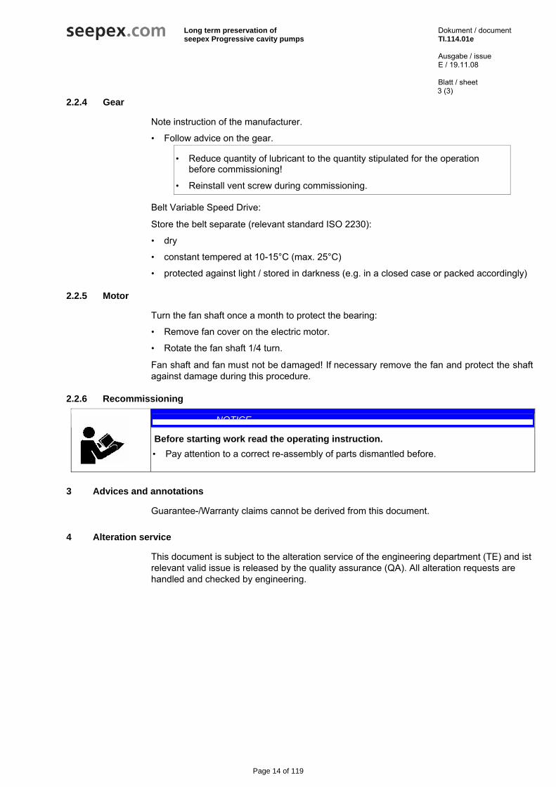
2.2.4 Gear
Note instruction of the manufacturer.
Ausgabe / issue E / 19.11.08 Blatt / sheet
3 (3)
• Follow advice on the gear.
• Reduce quantity of lubricant to the quantity stipulated for the operation before commissioning!
• Reinstall vent screw during commissioning.
Belt Variable Speed Drive:
Store the belt separate (relevant standard ISO 2230):
• dry
• constant tempered at 10-15°C (max. 25°C)
• protected against light / stored in darkness (e.g. in a closed case or packed accordingly)
2.2.5 Motor
Turn the fan shaft once a month to protect the bearing:
• Remove fan cover on the electric motor.
• Rotate the fan shaft 1/4 turn.
Fan shaft and fan must not be damaged! If necessary remove the fan and protect the shaft against damage during this procedure.
2.2.6 Recommissioning
NOTICE
Before starting work read the operating instruction.
• Pay attention to a correct re-assembly of parts dismantled before.
3 Advices and annotations
Guarantee-/Warranty claims cannot be derived from this document.
4 Alteration service
This document is subject to the alteration service of the engineering department (TE) and ist relevant valid issue is released by the quality assurance (QA). All alteration requests are handled and checked by engineering.
Page 14 of 119

f:\seepex\terms.doc 7.95
seepex, Inc. 511 Speedway Drive Enon, OH 45323 Phone (937) 864-7150
Fax (937) 864-7157 www.seepex.com [email protected]
TERMS & CONDITIONS OF SALES AND/OR REPAIR The following terms and conditions shall apply to an order for all or any part the articles covered by this quotation unless specifically excepted therein: Prices Any prices quoted shall only be valid for orders placed within 30 days from the date of issue of the quotation. Prices are F.O.B. our plant in U.S. or Canadian dollars. We reserve the right to correct typographical or clerical errors. Terms All orders are subject to approval by our Credit Department. Unless otherwise stated, if payment for the invoice due is not made within thirty (30) days after shipment, administration fees of eighteen percent (18%) per year (equivalent to a nominal monthly interest rate of 1½%) will be applied on overdue accounts. The terms and conditions herein set forth are based upon tariffs, taxes, foreign exchange rates, delivery, and other conditions in effect on the date of this contract. In the event changed conditions, legislations, regulations, or other matters shall become applicable to any quotation, contract, or delivery hereunder, any increased exchange, duties, taxes, ocean freight, or other charges resulting from such action shall be for the customer's account and seepex, Inc. may charge such increased duties, taxes, or charges to the customer. Unless the order includes the appropriate exemption certificates and/or licenses, duties, and taxes levied by Federal, State, or other governments are required to be charged automatically at the rate imposed at time of importation/shipment. Any change in law, regulations, or Government Department practice which causes a variation of any kind in the applicable charges from the amounts allowed for the quotation, shall result in an equivalent change in the price quoted. Until payment is made in full, seepex, Inc. shall retain the right, without notice, to repossess and/or retain the items, and/or dispose of them, for its benefit and hold the customer responsible for any loss. Customer agrees to enter into any agreements, contracts, or notices required to confirm such rights. Security In order to secure any obligations due to seepex, Inc. from the customer (whether or not under this contract) the customer grants and confirms in seepex, Inc. a security interest in: a) the merchandise covered by this contract,
and b) in all property and funds of the customer
now or hereafter in seepex, Inc. possession, whether or not arising out of this contract, and in all additions, accessions, and proceeds of such merchandise and/or property. The customer hereby authorizes seepex, Inc. to sign alone any financing statement or statements and to do all and any other things which may be necessary to perfect such security interest.
Cancellation After acceptance, orders may be canceled only with our approval and payment in accordance with contract by the customer for work performed and/or material expenses incurred by us to date of cancellation. We reserve the right to cancel the order if the customer's financial condition, in our sole judgment, places the payment in jeopardy. Return No credit will be allowed for returns unless our authorization in writing for such returns has been obtained beforehand. A copy of this authorization is to be returned with the item as the packing slip. Shipment a) Handling Charge: Customer shall be
responsible for making all arrangements for shipment of the order with a suitable carrier. In the event that customer requests that seepex make arrangements for shipment, then customer agrees to pay to seepex, in addition to the applicable shipping charges, a handling charge in the amount of 10% of the shipping charges with a minimum $5.00 to a maximum charge of $150.00, with special services requiring additional charges.
b) New Articles: Where shipping instructions indicate no exact routing, our best judgement will be used in determining routing but we shall not be liable for any charges beyond F.O.B. point. If changes are made at customer's request in a) F.O.B. point, b) in our normal routing from either the manufacturers' or our own plants and in these changes involve extra costs, such costs shall be for the customer's account, unless otherwise noted on the seepex price quotation.
c) Repair Work: Defined as work and services performed by seepex, Inc. All orders shall be delivered to and picked up from our plant unless otherwise specified. All costs of delivery shall be for the customer's account unless otherwise agreed to in writing prior to shipment.
d) All Orders: On collect freight shipments, cartage charges from plant to carrier are for customer's account. Title to articles passes to customer upon delivery to carrier acting as customer's agent subject to any right of retention by us. All claims for shortage in, and damages in, shipment or otherwise must be reported to carrier immediately upon receipt with copy or report to ourselves within five (5) days.
Guarantee a) New Articles: We guarantee articles of our
manufacture against defects in material and/or workmanship for a period of three (3) years from date of acceptance, providing that the articles have been installed, maintained, and operated in accordance with our recommendations and instructions.
b) Repair Work: Defined herein as work and services performed by seepex, Inc. We
guarantee all work and services performed by us against defect arising from workmanship and/or materials provided by us for a period of ninety (90) calendar days from the date of shipment to customer.
c) All Orders: Claims shall be submitted promptly in writing to seepex, Inc. Replacement and/or repair under guarantee shall be made F.O.B. our plant. Our liability under these guarantees is limited to the replacement and/or repair only of defective material or workmanship and in no event shall seepex, Inc. be liable for any loss or damage of whatever kind of nature out of defects in material and/or workmanship, or resulting from delay, or loss of use of articles, or any installation into which the article may be installed, or arising out, of the contract of the work or service or from negligence. seepex, Inc. shall not be liable for any loss or damage resulting from delay and/or late delivery due to causes beyond our reasonable control. In no event shall seepex, Inc. be liable for any claim exceeding the amount of this order. Our guarantee on products of other than our own manufacture is limited to the guarantee extended to us by the original manufacturer. On any claims for repairs and/or replacement under such guarantee, all costs incurred by us which are not underwritten by the original manufacturers shall be for the claimant's account. Except as stated above no representations, conditions, or warranties are made with respect to products, work, or services, express or implied verbal or otherwise, including warranties of merchantability and fitness. Our guarantee and warranty shall not apply to materials or workmanship which have been subject to misuse, neglect, or accident. seepex, Inc. shall be held free and harmless from any dispute or claim anywhere arising relating to infringement of patent, design, trademark, or copyright of items, sold or repaired under this contract.
Property rights and risks The customer's property at all times shall remain at the risk of the customer while being worked on by our personnel or on our premises and shall not be responsible for any loss or damage to the customer's property resulting from any cause whatsoever. Title to and rights in relation to item sold under this contract/quotations shall remain with seepex, Inc. until such items are paid for, subject to risk on products sold passing to the customer upon acceptance by a carrier or other, which shall constitute good delivery.
Page 15 of 119

Warranty Card Complete and return to validate warranty
Please complete this card and return it to seepex Inc. By using this card, the valid warranty period will commence at the pump “start-up” date. If this card is not completed the warranty coverage period will commence on the date the pump is shipped fromthe seepex factory. This card must be completed and mailed no later than one year from the date of shipment. User Entity: _______________________ Mailing Address: ________________________ Pump Model # _____________________
________________________ Pump Commission #: _____________________ ________________________ Pumped Product: _____________________
Contact Person: _______________________ Diff. Pressure: _________ Flow Rate: ________ Phone Number: ________________________ Temperature: _________ Visosity: _________ Fax Number: ________________________ Solids Size: _________ Solids %: _________
Was the pump delivered as scheduled? __ Yes __ No Did the pump perform as expected? __ Yes __ No Was the appearance of the pump acceptable? __ Yes __ No Did you receive: - Data Sheets? __ Yes __ No Did the pump suffer any freight damage? __ Yes __ No -O&M Manuals? __ Yes __ No Did you local seepex distributor contact you to arrange a start-up? __ Yes __ No Other Comments: ______________________________________________________________________________________ ______________________________________________________________________________________ Name of person completing card (please print): _______________________________________________________________ Date: ________________ Signature: _____________________________________
Page 16 of 119

PRODUCT PROFILE
GENERICDESCRIPTION PhenolicAlkyd
COMMONUSAGE Lead-andchromate-free,fast-drying,corrosion-resistantprimerthatacceptsavarietyofhigh-performancetopcoats.Ideallysuitedforsteelfabricators,OEM’sandfieldapplicationswhere“dry-fall”characteristicsaredesired.Note:Notrecommendedforimmersion.
COLORS 77Red,77WWhite,78Gray
PERFORMANCECRITERIA Extensivetestdataavailable.ContactyourTnemecrepresentativeforspecifictestresults.
COATING SYSTEM
TOPCOATS Series2H,6,23,27,28,29,30,66,N69,73,113,114,161,175,180,181,1074,1075. Note:Somesystemsarenotrecommendedforfrequentlysweatingorcontinuallywetcondi-
tions.Referencetheapplicabletopcoatdatasheetforadditionalinformation.Also,anaddi-tionalcoatof37HissuggestedbeforeapplyingSeries6,180or181.ContactTnemecTechnicalServicesfordetails.
SURFACE PREPARATION
STEEL Enclosed or Protected:SSPC-SP3PowerToolCleaning Weather-Exposed:SSPC-SP6/NACE3CommercialBlastCleaning
CAST/DUCTILEIRON ContactyourTnemecrepresentativeorTnemecTechnicalServices.
ALLSURFACES Mustbeclean,dryandfreeofoil,greaseandothercontaminants.
TECHNICAL DATA
VOLUMESOLIDS* 58.0±2.0%
RECOMMENDEDDFT 2.0to3.5mils(50to90microns)percoat.
CURINGTIME Temperature To Handle To Recoat With Series:
75°F(24°C) 2hours 2H,23, 27•,66• 28,29, N69,73,113,114, 180,181 161• 30 175,1074,1075
12hours 48hours 7days 30days
Curingtimevarieswithsurfacetemperature,airmovement,humidityandfilmthickness. •Note:Allow37Htocure14daysif27,66or161istobeusedasanintermediatecoatand
topcoatedwith73,175,1074or1075.Thenallow27,66or161tocureanadditional24hoursbeforetopcoating.
Water Tank Exteriors:Fivedaysormorecuringrequiredbeforefilling.
VOLATILEORGANIC Unthinned Thinned 4% Thinned 9% COMPOUNDS* 2.91lbs/gallon 3.07lbs/gallon 3.27lbs/gallon (348grams/litre) (368grams/litre) (391grams/litre) HAPS 1.37lbs/galsolids 1.89lbs/galsolids 2.51lbs/galsolids
THEORETICALCOVERAGE* 930milsqft/gal(22.8m2/Lat25microns).SeeAPPLICATIONforcoveragerates.
NUMBEROFCOMPONENTS One
PACKAGING 55gallon(208.2L)drums,5gallon(18.9L)pailsand1gallon(3.79L)cans.
NETWEIGHTPERGALLON* 77 12.83±0.25lbs(5.92±.11kg) 77W 12.70±0.25lbs(5.88±.11kg) 78 12.11±0.25lbs(5.61±.11kg)
STORAGETEMPERATURE Minimum20°F(-7°C) Maximum110°F(43°C)
TEMPERATURERESISTANCE (Dry)Continuous200°F(93°C) Intermittent250°F(121°C)
SHELFLIFE 24monthsatrecommendedstoragetemperature.
FLASHPOINT-SETA 65°F(18°C)
Chem-Prime H.S. SERIES37H
©December11,2006,byTnemecCompany,Inc. 37H
Publ i shed techn ica l dataand ins t ruc t ionsaresub jec t to changewi thout not i ce. Theon l inecata logat www.tnemec.comshouldbe re ferenced for themostcur rent techn ica l dataand ins t ruc t ionsor youmaycontact your Tnemec representat ive fo r cur rent techn ica l dataand ins t ruc t ions.
®
Page 17 of 119

WARRANTY&LIMITATIONOFSELLER’SLIABILITY:TnemecCompany,Inc.warrantsonlythatitscoatingsrepresentedhereinmeettheformulationstandardsofTnemecCompany,Inc.THEWARRANTYDESCRIBEDINTHEABOVEPARAGRAPHSHALLBEINLIEUOFANYOTHERWARRANTY,EXPRESSEDORIMPLIED,INCLUDINGBUTNOTLIMITEDTO,ANYIMPLIEDWARRANTYOFMERCHANTABILITYORFITNESSFORAPARTICULARPURPOSE.THEREARENOWARRANTIESTHATEXTENDBEYONDTHEDESCRIPTIONONTHEFACEHEREOF.Thebuyer’ssoleandexclusiveremedyagainstTnemecCompany,Inc.shallbeforreplacementoftheproductintheeventadefectiveconditionoftheproductshouldbefoundtoexistandtheexclusiveremedyshallnothavefaileditsessentialpurposeaslongasTnemeciswillingtoprovidecomparablereplacementproducttothebuyer.NOOTHERREMEDY(INCLUDING,BUTNOTLIMITEDTO,INCIDENTALORCONSEQUENTIALDAMAGESFORLOSTPROFITS,LOSTSALES,INJURYTOPERSONORPROPERTY,ENVIRONMENTALINJURIESORANYOTHERINCIDENTALORCONSEQUENTIALLOSS)SHALLBEAVAILABLETOTHEBUYER.Technicalandapplicationinformationhereinisprovidedforthepurposeofestablishingageneralprofileofthecoatingandpropercoatingapplicationprocedures.TestperformanceresultswereobtainedinacontrolledenvironmentandTnemecCompanymakesnoclaimthatthesetestsoranyothertests,accuratelyrepresentallenvironments.Asapplication,environmentalanddesignfactorscanvarysignificantly,duecareshouldbeexercisedintheselectionanduseofthecoating.FOR INDUSTRIAL USE ONLY.
TNEMECCOMPANYINCORPORATED PRINTEDINUSA6800CORPORATEDRIVE,KANSASCITY,MISSOURI64120-1372 TEL:1800TNEMEC1 www.tnemec.com (YDAT300) 37H
TECHNICAL DATA continued
HEALTH&SAFETY Paintproductscontainchemicalingredientswhichareconsideredhazardous.ReadcontainerlabelwarningandMaterialSafetyDataSheetforimportanthealthandsafetyinformationpriortotheuseofthisproduct.Keep out of the reach of children.
APPLICATION
CAUTION! Dryoverspraycanbewipedorwashedfrommostsurfaces.Satisfactorydry-fallperformancedependsuponheightofwork,weatherconditions,equipmentadjustmentandproperthinning.Testforeachapplicationasfollows:Sprayfrom15to25feettowardspaintcontainer.Themate-rialthenshouldreadilywipeoff.Note:Heatcanfuse-dryoverspraytosurfaces.Alwayscleandryoversprayfromhotsurfacesbeforefusingoccurs.Beawarethatexteriorsurfacetemperaturescanbehigherthanairtemperature.
COVERAGERATES* Dry Mils Wet Mils Sq Ft/Gal (Microns) (Microns) (m2/Gal) Suggested 2.5(65) 4.5(115) 372(34.6) Minimum 2.0(50) 3.5 (90) 465(43.2) Maximum 3.5(90) 6.0(150) 266(24.7)
Allowforoversprayandsurfaceirregularities.Wetfilmthicknessisroundedtothenearest0.5milor5microns.Applicationofcoatingbelowminimumorabovemaximumrecommendeddryfilmthicknessesmayadverselyaffectcoatingperformance.
MIXING Stirthoroughly,makingsurenopigmentremainsonthebottomofthecan.
THINNING UseNo.2Thinner.Forairspray,thinupto9%pergallon.Forairlessspray,brushorroller,thinupto4%pergallon.
SURFACETEMPERATURE Minimum40°F(4°C) Maximum120°F(49°C) Thesurfaceshouldbedryandatleast5°F(3°C)abovethedewpoint.
APPLICATIONEQUIPMENT Air Spray Gun Fluid Air Cap Air Hose Mat’l Hose Atomizing Pot Tip ID ID Pressure Pressure
DeVilbiss E 765 5/16”or3/8” 3/8”or1/2” 75-90psi 10-20psi JGA or704 (7.9or9.5mm) (9.5or12.7mm) (5.2-6.2bar) (0.7-1.4bar)
Lowtemperaturesorlongerhosesrequirehigherpotpressure.
Airless Spray Tip Orifice Atomizing Pressure Mat’l Hose ID Manifold Filter
0.015”-0.019” 2700-3000psi 1/4”or3/8” 60mesh (380-485microns) (186-207bar) (6.4or9.5mm) (250microns)
Useappropriatetip/atomizingpressureforequipment,applicatortechniqueandweatherconditions.
Roller: Usehighqualitysyntheticwovennapcovers.Shortnapforsmoothsurfaces.Longnapforroughsurfaces.
Brush: Recommendedforsmallareasonly.Usehighqualitynylonorsyntheticbristlebrushes.
CLEANUP Flushandcleanallequipmentimmediatelyafterusewiththerecommendedthinnerorxylol.
*Valuesmayvarywithcolor.
SERIES37H Chem-Prime H.S.
Page 18 of 119

PRODUCT PROFILE
GENERICDESCRIPTION PolyamidoamineEpoxy
COMMONUSAGE Anadvancedgenerationepoxyforprotectionandfinishingofsteelandconcrete.Ithasexcellentresis-tancetoabrasionandissuitableforimmersionaswellaschemicalcontactexposure.ContactyourlocalTnemecrepresentativeforalistofchemicals.Thisproductcanalsobeusedforliningstoragetanksthatcontaindemineralized,deionizedordistilledwater.
COLORS RefertoTnemecColorGuide.Note:Epoxieschalkwithextendedexposuretosunlight.Lackofventila-tion,incompletemixing,miscatalyzationortheuseofheatersthatemitcarbondioxideandcarbonmon-oxideduringapplicationandinitialstagesofcuringmaycauseyellowingtooccur.
FINISH Satin
SPECIALQUALIFICATIONS Atwo-coatsystemat4.0-6.0drymils(100-150drymicrons)percoatpassestheperformancerequire-mentsofMIL-C-4556Eforfuelstorage.
PERFORMANCECRITERIA Extensivetestdataavailable.ContactyourTnemecrepresentativeforspecifictestresults.
COATING SYSTEM
PRIMERS Steel:Self-primingorSeries1,27,37H,66,90,91-H2O,94-H2O,135,161,394,530 Galvanized Steel and Non-Ferrous Metal:Self-primingorSeries66,161 Concrete:Self-primingor54-660,130,218,219 CMU:Self-primingor54-562,54-660,130,216,218,219
TOPCOATS 46H-413,66,L69,N69,73,84,104,113,114,161,1070,1071,1072,1074,1074U,1075,1075U,1077,1078.RefertoCOLORSonapplicabletopcoatdatasheetsforadditionalinformation.Note:ThefollowingrecoattimesapplyforSeriesN69/V69:ImmersionService—Surfacemustbescarifiedafter60days.AtmosphericService—After60days,scarificationoranepoxytie-coatisrequired.ContactyourTnemecrepresentativeforspecificrecommendations.
SURFACE PREPARATION
STEEL Immersion Service:SSPC-SP10/NACE2Near-WhiteBlastCleaning Non-Immersion Service:SSPC-SP6/NACE3CommercialBlastCleaning
PRIMEDSTEEL Immersion Service:ScarifytheSeries66,N69/V69or161primecoatsurfacebyabrasiveblastingwithfineabrasivebeforetopcoatingifithasbeenexteriorexposedfor60daysorlongerandN69/V69isthespecifiedtopcoat.
GALVANIZEDSTEEL& Surfacepreparationrecommendationswillvarydependingonsubstrateandexposureconditions. NON-FERROUSMETAL ContactyourTnemecrepresentativeorTnemecTechnicalServices.
CAST/DUCTILEIRON ContactyourTnemecrepresentativeorTnemecTechnicalServices.
CONCRETE Allownewconcretetocure28days.Foroptimumresultsand/orimmersionservice,abrasiveblastrefer-encingSSPC-SP13/NACE6,ICRICSP2-4SurfacePreparationofConcreteandTnemec’sSurfacePrepara-tionandApplicationGuide.
CMU Allowmortartocurefor28days.Levelprotrusionsandmortarspatter.
PAINTEDSURFACES Non-Immersion Service:AskyourTnemecrepresentativeforspecificrecommendations.
ALLSURFACES Mustbeclean,dryandfreeofoil,grease,chalkandothercontaminants.
TECHNICAL DATA
VOLUMESOLIDS* 67.0±2.0%(mixed)
RECOMMENDEDDFT 2.0to10.0mils(50to255microns)percoat.Note: MIL-C-4556Eapplicationsrequiretwocoatsat4.0-6.0mils(100-150microns)percoat.Otherwise,thenumberofcoatsandthicknessrequirementswillvarywithsubstrate,applicationmethodandexposure.ContactyourTnemecrepresentative.
CURINGTIMEAT5MILSDFT Temperature To Handle To Recoat Immersion Without44-700Accelerator 90°F(32°C) 4hours 7hours 6days 80°F(27°C) 5hours 8hours 7days 70°F(21°C) 7hours 10hours 7days 60°F(16°C) 8hours 12hours 9days
50°F(10°C) 12hours 16hours 12days
Curingtimevarieswithsurfacetemperature,airmovement,humidityandfilmthickness.Note:Forfastercur-ingandlow-temperatureapplications,addNo.44-700EpoxyAccelerator;seeseparateproductdatasheet.
VOLATILEORGANIC N69: Unthinned Thinned 10% Thinned 10% V69: Unthinned Thinned 2.5% COMPOUNDS* No. 4 Thinner No. 60 Thinner 2.40lbs/gallon 2.80lbs/gallon 2.80lbs/gallon 1.95lbs/gallon 2.08lbs/gallon
(285grams/litre) (334grams/litre) (335grams/litre) (234grams/litre) (250grams/litre)
HAPS 2.40lbs/galsolids 3.25lbs/galsolids 2.40lbs/galsolids 2.00lbs/galsolids 2.30lbs/galsolids
THEORETICALCOVERAGE* 1,074milsqft/gal(26.4m2/Lat25microns).SeeAPPLICATIONforcoveragerates.
NUMBEROFCOMPONENTS Two:PartAandPartB
PACKAGING 5gallon(18.9L)pailsand1gallon(3.79L)cans—Orderinmultiplesof2.
Hi-Build Epoxoline II SERIESN69
©April17,2007,byTnemecCompany,Inc. N69
Publ i shed techn ica l dataand ins t ruc t ionsaresub jec t to changewi thout not i ce. Theon l inecata logat www.tnemec.comshouldbe re ferenced for themostcur rent techn ica l dataand ins t ruc t ionsor youmaycontact your Tnemec representat ive fo r cur rent techn ica l dataand ins t ruc t ions.
®
SeriesV69conformswithairpollutionregulationslimitingVolatileOrganicCompounds(VOC)toamaximumof250grams/litre(2.08lbs/gal)Inareasrequiringlessthan100grams/litreVOC,pleaserefertotheSeriesL69datasheet.
Page 19 of 119
WARRANTY&LIMITATIONOFSELLER’SLIABILITY:TnemecCompany,Inc.warrantsonlythatitscoatingsrepresentedhereinmeettheformulationstandardsofTnemecCompany,Inc.THEWARRANTYDESCRIBEDINTHEABOVEPARAGRAPHSHALLBEINLIEUOFANYOTHERWARRANTY,EXPRESSEDORIMPLIED,INCLUDINGBUTNOTLIMITEDTO,ANYIMPLIEDWARRANTYOFMERCHANTABILITYORFITNESSFORAPARTICULARPURPOSE.THEREARENOWARRANTIESTHATEXTENDBEYONDTHEDESCRIPTIONONTHEFACEHEREOF.Thebuyer’ssoleandexclusiveremedyagainstTnemecCompany,Inc.shallbeforreplacementoftheproductintheeventadefectiveconditionoftheproductshouldbefoundtoexistandtheexclusiveremedyshallnothavefaileditsessentialpurposeaslongasTnemeciswillingtoprovidecomparablereplacementproducttothebuyer.NOOTHERREMEDY(INCLUDING,BUTNOTLIMITEDTO,INCIDENTALORCONSEQUENTIALDAMAGESFORLOSTPROFITS,LOSTSALES,INJURYTOPERSONORPROPERTY,ENVIRONMENTALINJURIESORANYOTHERINCIDENTALORCONSEQUENTIALLOSS)SHALLBEAVAILABLETOTHEBUYER.Technicalandapplicationinformationhereinisprovidedforthepurposeofestablishingageneralprofileofthecoatingandpropercoatingapplicationprocedures.TestperformanceresultswereobtainedinacontrolledenvironmentandTnemecCompanymakesnoclaimthatthesetestsoranyothertests,accuratelyrepresentallenvironments.Asapplication,environmentalanddesignfactorscanvarysignificantly,duecareshouldbeexercisedintheselectionanduseofthecoating.FOR INDUSTRIAL USE ONLY.
TNEMECCOMPANYINCORPORATED PRINTEDINUSA6800CORPORATEDRIVE,KANSASCITY,MISSOURI64120-1372 TEL:1800TNEMEC1 www.tnemec.com (YDAT067) N69
TECHNICAL DATA continued
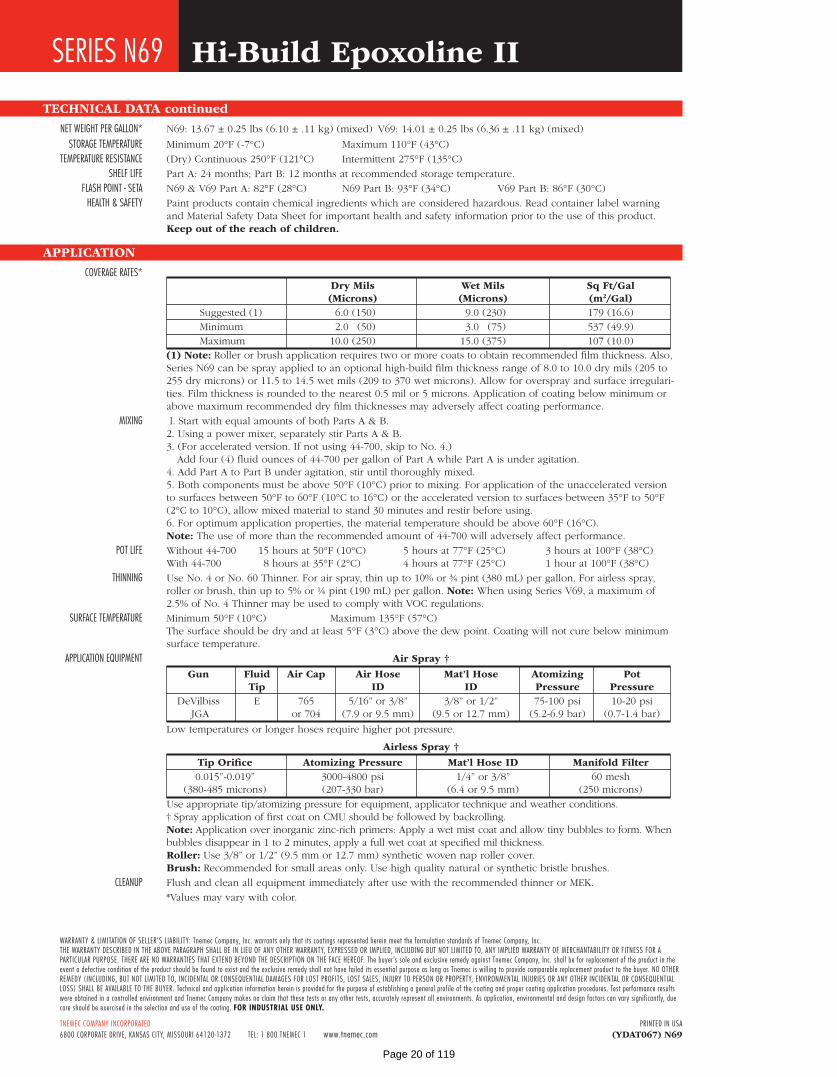
NETWEIGHTPERGALLON* N69:13.67±0.25lbs(6.10±.11kg)(mixed) V69:14.01±0.25lbs(6.36±.11kg)(mixed)
STORAGETEMPERATURE Minimum20°F(-7°C) Maximum110°F(43°C)
TEMPERATURERESISTANCE (Dry)Continuous250°F(121°C) Intermittent275°F(135°C)
SHELFLIFE PartA:24months;PartB:12monthsatrecommendedstoragetemperature.
FLASHPOINT-SETA N69&V69PartA:82°F(28°C) N69PartB:93°F(34°C) V69PartB:86°F(30°C)
HEALTH&SAFETY Paintproductscontainchemicalingredientswhichareconsideredhazardous.ReadcontainerlabelwarningandMaterialSafetyDataSheetforimportanthealthandsafetyinformationpriortotheuseofthisproduct.Keep out of the reach of children.
APPLICATION
COVERAGERATES* Dry Mils Wet Mils Sq Ft/Gal (Microns) (Microns) (m2/Gal) Suggested(1) 6.0(150) 9.0(230) 179(16.6) Minimum 2.0 (50) 3.0 (75) 537(49.9) Maximum 10.0(250) 15.0(375) 107(10.0) (1) Note: Rollerorbrushapplicationrequirestwoormorecoatstoobtainrecommendedfilmthickness.Also,
SeriesN69canbesprayappliedtoanoptionalhigh-buildfilmthicknessrangeof8.0to10.0drymils(205to255drymicrons)or11.5to14.5wetmils(209to370wetmicrons).Allowforoversprayandsurfaceirregulari-ties.Filmthicknessisroundedtothenearest0.5milor5microns.Applicationofcoatingbelowminimumorabovemaximumrecommendeddryfilmthicknessesmayadverselyaffectcoatingperformance.
MIXING l.StartwithequalamountsofbothPartsA&B. 2.Usingapowermixer,separatelystirPartsA&B. 3.(Foracceleratedversion.Ifnotusing44-700,skiptoNo.4.) Addfour(4)fluidouncesof44-700pergallonofPartAwhilePartAisunderagitation. 4.AddPartAtoPartBunderagitation,stiruntilthoroughlymixed. 5.Bothcomponentsmustbeabove50°F(10°C)priortomixing.Forapplicationoftheunacceleratedversion
tosurfacesbetween50°Fto60°F(10°Cto16°C)ortheacceleratedversiontosurfacesbetween35°Fto50°F(2°Cto10°C),allowmixedmaterialtostand30minutesandrestirbeforeusing.
6.Foroptimumapplicationproperties,thematerialtemperatureshouldbeabove60°F(16°C). Note:Theuseofmorethantherecommendedamountof44-700willadverselyaffectperformance.
POTLIFE Without44-700 15hoursat50°F(10°C) 5hoursat77°F(25°C) 3hoursat100°F(38°C) With44-700 8hoursat35°F(2°C) 4hoursat77°F(25°C) 1hourat100°F(38°C)
THINNING UseNo.4orNo.60Thinner.Forairspray,thinupto10%or¾pint(380mL)pergallon.Forairlessspray,rollerorbrush,thinupto5%or¼pint(190mL)pergallon.Note:WhenusingSeriesV69,amaximumof2.5%ofNo.4ThinnermaybeusedtocomplywithVOCregulations.
SURFACETEMPERATURE Minimum50°F(10°C) Maximum135°F(57°C) Thesurfaceshouldbedryandatleast5°F(3°C)abovethedewpoint.Coatingwillnotcurebelowminimum
surfacetemperature.
APPLICATIONEQUIPMENT Air Spray †
Gun Fluid Air Cap Air Hose Mat’l Hose Atomizing Pot Tip ID ID Pressure Pressure DeVilbiss E 765 5/16”or3/8” 3/8”or1/2” 75-100psi 10-20psi JGA or704 (7.9or9.5mm) (9.5or12.7mm) (5.2-6.9bar) (0.7-1.4bar)
Lowtemperaturesorlongerhosesrequirehigherpotpressure.
Airless Spray †
Tip Orifice Atomizing Pressure Mat’l Hose ID Manifold Filter 0.015”-0.019” 3000-4800psi 1/4”or3/8” 60mesh (380-485microns) (207-330bar) (6.4or9.5mm) (250microns)
Useappropriatetip/atomizingpressureforequipment,applicatortechniqueandweatherconditions. †SprayapplicationoffirstcoatonCMUshouldbefollowedbybackrolling. Note: Applicationoverinorganiczinc-richprimers:Applyawetmistcoatandallowtinybubblestoform.When
bubblesdisappearin1to2minutes,applyafullwetcoatatspecifiedmilthickness. Roller: Use3/8”or1/2”(9.5mmor12.7mm)syntheticwovennaprollercover. Brush: Recommendedforsmallareasonly.Usehighqualitynaturalorsyntheticbristlebrushes.
CLEANUP FlushandcleanallequipmentimmediatelyafterusewiththerecommendedthinnerorMEK.
*Valuesmayvarywithcolor.
SERIESN69 Hi-Build Epoxoline II
Page 20 of 119

Page 21 of 119

Page 22 of 119

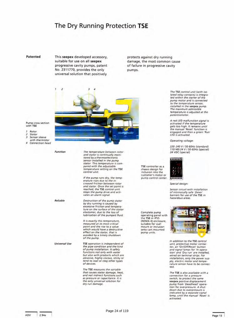
short instruction dry running protection device TSE
Dokument / document ZU.TSE.05e Ausgabe / issue A / 24.01.96 Blatt / sheet
1 (1)
1. Important notice This instruction gives details on how to plan the electrical connection and adjustment of the trip temperature. For further information and prior to commissioning it is important that the complete operating and maintenance instructions for the pump are strictly observed.
2. Electrical connection Electrical connection has to be effected acc. to the following diagram. Prior to installation, the voltage indicated on the TSE-controller has to be compared with the existing supply voltage. NTC 10 kΩ RESET supply contact voltage
Important: function of contacts K1/K2: actual temperature < shutdown temperature (troublefree operation) contact 6-7 and 9-10 closed contact 6-5 and 9-8 open actual temperature > shutdown temperature (trouble/dry running) contact 6-5 and 9-8 closed contact 6-7 and 9-10 open
3. Adjustment of trip temperature The TSE-controller is supplied with a trip temperature set at 50 °C. To achieve the shortest possible switch-off time at dry running and to have optimum pump stator protection, the trip temperature of the TSE-controller should be set as low as possible. When commissioning, the set temperature of 50°C should not be changed. Only when operating with higher product temperatures must the set point be adjusted to 20 - 30 °C above the product temperature. Procedure: Switching-on control voltage! When self-testing the TSE-controller, the display shows the actual set trip temperature
P
press and release button: adjusting mode is activated. The display shows alternately „SET“ and the last set trip temperature.
Increasing the trip temperature - press button and release: The adjusted temperature increases by +1°. Press button and hold approx. 3 sec. in +10° steps.
reset
Decreasing of trip temperature - press button and release: The adjusted temperature decreases by - 1°. Press button and hold approx. 3 sec. in - 10° steps.
P
press and release button: returns the unit to the operating mode. The adjusted trip temperature is transferred to a continuous memory and shown on the display.
Notice During the adjusting mode if a button is not pressed within 10 seconds the controller automatically returns to the operating mode and disregards any previous adjustments.
Following the above instructions the seepex pump has to be in operation for at least 30 minutes to allow the operating temperature in the stator to become stable. While the pump is in operation, the measured temperature of the pump is shown on the display of the TSE-controller by continuous pressing of the
button.
statortemp.
The final trip temperature has now to be adjusted 5-10°C higher than the indicated operating temperature.
ϑ↑↓
Page 23 of 119
Page 24 of 119

Page 25 of 119
Page 26 of 119

Page 27 of 119
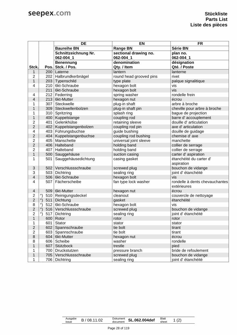
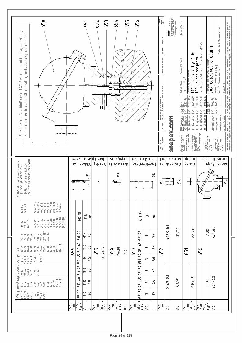
StücklisteParts List
Liste des pièces
Ausgabe issue B / 08.11.02 Dokument
document SL.062.004def Blatt sheet 1 (2)
DE EN FR Baureihe BN Range BN Série BN Schnittzeichnung Nr. sectional drawing no. plan no. 062-004_1 062-004_1 062-004_1 Benennung denomination désignation
Stck. Pos. Stck. / Pos. Qty. / Item Qté. / Poste 1 200 Laterne lantern lanterne 2 202 Halbrundkerbnägel round head grooved pins rivet 1 203 Typenschild type plate palque signalitique 4 210 6kt-Schraube hexagon bolt vis
211 6kt-Schraube hexagon bolt vis 4 212 Federring spring washer rondelle frein 4 213 6kt-Mutter hexagon nut écrou 1 307 Steckwelle plug-in shaft arbre à broche 1 309 Steckwellenbolzen plug-in shaft pin cheville pour arbre à broche 1 310 Spritzring splash ring bague de projection 1 400 Kuppelstange coupling rod barre d' accouplement 2 401 Gelenkhülse retaining sleeve douille d' articulation 2 402 Kuppelstangenbolzen coupling rod pin axe d' articulation 4 403 Führungsbuchse guide bushing douille de guidage 2 404 Kuppelstangenbuchse coupling rod bushing chemise d' axe 2 405 Manschette universal joint sleeve manchette 2 406 Halteband holding band collier de serrage 2 407 Halteband holding band collier de serrage 1 500 Sauggehäuse suction casing carter d' aspiration 1 501 Sauggehäusedichtung casing gasket étanchéité du carter d'
aspiration 3 502 Verschlussschraube screwed plug bouchon de vidange 3 503 Dichtring sealing ring joint d' étanchéité 4 506 6kt-Schraube hexagon bolt vis 4 507 Fächerscheibe fan type lock washer rondelle à dents chevauchantes
extérieures 4 509 6kt-Mutter hexagon nut écrou 2 °) 510 Reinigungsdeckel cleanout couvercle de nettoyage 2 °) 511 Dichtung gasket étanchéité 8 °) 512 6kt-Schraube hexagon bolt vis 2 °) 516 Verschlussschraube screwed plug bouchon de vidange 2 °) 517 Dichtring sealing ring joint d' étanchéité 1 600 Rotor rotor rotor 1 601 Stator stator stator 2 602 Spannschraube tie bolt tirant 2 603 Spannschraube tie bolt tirant 8 604 6kt-Mutter hexagon nut écrou 8 606 Scheibe washer rondelle 1 607 Stützbock trestle pied 1 700 Druckstutzen pressure branch bride de refoulement 1 705 Verschlussschraube screwed plug bouchon de vidange 1 706 Dichtring sealing ring joint d' étanchéité
Page 28 of 119

StücklisteParts List
Liste des pièces
Ausgabe issue B / 08.11.02 Dokument
document SL.062.004def Blatt sheet 2 (2)
DE EN FR Baureihe BN Range BN Série BN Schnittzeichnung Nr. sectional drawing no. plan no. 062-004_1 062-004_1 062-004_1 Benennung denomination désignation
Stck. Pos. Stck. / Pos. Qty. / Item Qté. / Poste 098 seepex Gelenkfett seepex joint grease seepex graisse d' articulations
Typ und Füllmenge: type and filling quantity: sommaire pour type et quantité:Betriebs- und Wartungsanleitung entnehmen
see Operating and Maintenance Instruction
voir Instructions de service et d'entretien
Verschleißteile und Dichtungen: Wear parts and sealings: pièces d'usure et étanchéités: Betriebs- und Wartungsanleitung entnehmen
see Operating and Maintenance Instruction
voir Instructions de service et d'entretien
Werkzeuge: Tools: Outils: Betriebs- und Wartungsanleitung entnehmen
see Operating and Maintenance Instruction
voir Instructions de service et d'entretien
Wellenabdichtung shaft sealing dispositif d' etanchéité siehe Schnittzeichnung Gleitringdichtung
see sectional drawing mechanical seal
voir vue éclatée garniture mécanique
versetzt gezeichnet drawn displaced plan separé °) Option option option
Page 29 of 119

40
1
41
1Cartex® Single pusher cartridge seals
Mec
hani
cal se
als
Mechanical seals · Mechanical seals for pumps · Standard cartridge seals
Features
• Single seal• Cartridge• Balanced• Independent of direction of rotation• Single seals without connections (-SNO), with fl ush (-SN) and with quench combined with lip seal (-QN) or throttle ring (-TN)
• Additional variants available for ANSI pumps (e. g.-ABPN) and eccentric screw pumps (-Vario)
Advantages
• Ideal seal for standardizations• Universal applicable for packings conversions, retrofi ts or original equipment
• No dimensional modifi cation of the seal chamber (centrifugal pumps) necessary, small radial installation height
• No dynamically loaded O-Ring• Extended service life• Installation faults are avoided, cost-effective• No damage caused by dirt entered during assembly• Straightforward and easy installation due to pre-assembled unit (reduced down-times)
• Individual adaptation to pump design possible• Customer specifi c versions available
Cartex-SN, -SNO, -QN, -TN, -Vario
Shaft diameter: d1 = 25 ... 100 mm (1.000" ... 4.000")Other sizes on requestTemperature: t = –40 °C ... +220 °C (–40 °F ... +428 °F)(Check O-Ring resistance)
Sliding face material combination BQ1Pressure: p1 = 25 bar (363 PSI)Sliding velocity: vg = 16 m/s (52 ft/s)
Sliding face material combination Q1Q1 or U2Q1Pressure: p1 = 12 bar (174 PSI)Sliding velocity: vg = 10 m/s (33 ft/s)
Axial movement: ±1.0 mm, d1 ≥ 75 mm ±1.5 mm
Operating range (see note on page 1)
Seal face: Silicon carbide (Q1), Carbon graphite resin impregnated (B), Tungsten carbide (U2)Seat: Silicon carbide (Q1)Secondary seals: FKM (V), EPDM (E), FFKM (K), Perfl ourocarbon rubber/PTFE (U1)Springs: Hastelloy® C-4 (M)Metal parts: CrNiMo steel (G), CrNiMo cast steel (G)
Materials
Recommended applications
• Process technology• Water supply and water treatment • Chemical and petrochemical industry• Pharmaceutical industry• Food and beverage industry• Universally applicable• Centrifugal pumps• Eccentric screw pumps• Process pumps
Item Description
1 Seal face 2, 5, 7 O-Ring 3 Spring 4 Seat 6 Shaft sleeve 8 Drive collar 9 Set screw 10 Snap ring 11 Cover 12 Assembly fi xture 13 Screw 14 Gasket 15 Screw plug 16 Lip seal (-QN), throttle ring (-TN)
45°45°A
sa1
da
45° 45°A
s
da
a1
Machined cover version
Cast cover version
Cartex-SNOSingle seal without connections, for dead-end operation.
Cartex-TNSingle seal for operation with unpressurized quench. Same as Cartex-SN but with throttle ring (item 16). The cover has auxiliary connections for fl ushing and quench. Throttle ring: PTFE carbon-graphite reinforced.
Cartex-QNSingle seal for operation with unpressurized quench. Same as “-SN” version but with outboard lip seal (item 16). The cover has auxiliary connections for fl ushing and quench. Lip seal: NBR (P), PTFE carbon reinforced (T3)
Cartex-VarioCartridge seals with modifi ed cover for eccentric screw pumps. For e. g. Seepex BN, Netzsch NM ... S, NM ... B, NE (P),Allweiler AE, AEB, AED,Robbins & Myers/Moyno 2000 CC and Mono E-Range.Please inquire.
Product variants
l13 l12
l14
l15
l16l17
15
16 16
15
l15
l17 l16
Cartex-SNO Cartex-TN Cartex-QN Cartex-Vario
Dimensions in mmd1 d2 d3min. d3max. l1 l2 l3 l4 l12 l13 l14 l15 l16 l17 a1 da s
25 43.0 44.0 51.5 67 42.4 24.6 25.4 35.0 32.0 17.5 79.5 53.4 26.1 62 105 13.228 46.0 47.0 52.0 67 42.4 24.6 25.4 35.0 32.0 17.5 79.5 53.4 26.1 62 105 13.230 48.0 49.0 56.0 67 42.4 24.6 25.4 35.0 32.0 17.5 79.5 53.4 26.1 65 105 13.232 49.8 51.0 57.0 67 42.4 24.6 25.4 35.0 32.0 17.5 79.5 53.4 26.1 67 110 13.233 49.8 51.0 57.0 67 42.4 24.6 25.4 35.0 32.0 17.5 79.5 53.4 26.1 67 110 13.235 53.0 54.0 61.5 67 42.4 24.6 25.4 35.0 32.0 17.5 79.5 53.4 26.1 70 113 13.238 56.0 57.0 66.0 67 42.4 24.6 25.4 35.0 32.0 17.5 79.5 53.4 26.1 75 123 13.240 58.0 59.0 68.0 67 42.4 24.6 25.4 35.0 32.0 17.5 79.5 53.4 26.1 75 123 14.242 60.5 61.5 69.5 67 42.4 24.6 25.4 35.0 32.0 17.5 79.5 53.4 26.1 80 133 14.243 60.5 61.5 70.5 67 42.4 24.6 25.4 35.0 32.0 17.5 79.5 53.4 26.1 80 133 14.245 62.5 64.0 73.0 67 42.4 24.6 25.4 35.0 32.0 17.5 79.5 53.4 26.1 81 138 14.248 65.6 67.0 75.0 67 42.4 24.6 25.4 35.0 32.0 17.5 79.5 53.4 26.1 84 138 14.250 68.0 69.0 78.0 67 42.4 24.6 25.4 35.0 32.0 17.5 79.5 53.4 26.1 87 148 14.253 72.0 73.0 87.0 67 42.4 24.6 25.4 35.0 32.0 17.5 79.5 53.4 26.1 97 148 18.055 73.0 74.0 83.0 67 42.4 24.6 25.4 35.0 32.0 17.5 79.5 53.4 26.1 90 148 18.060 78.0 79.0 91.0 67 42.4 24.6 25.4 35.0 32.0 17.5 79.5 53.4 26.1 102 157 18.065 84.8 85.7 98.5 67 42.4 24.6 25.4 35.0 32.0 17.5 79.5 53.4 26.1 109 163 18.070 93.0 95.0 108.0 67 42.4 24.6 25.4 35.0 32.0 17.5 79.5 53.4 26.1 118 178 18.075 100.0 101.6 118.0 84 57.4 26.6 28.0 46.1 37.9 22.0 98.0 63.9 34.1 129 190 18.080 106.4 108.0 124.0 84 57.4 26.6 28.0 46.1 37.9 22.0 98.0 63.9 34.1 135 195 18.085 109.5 111.1 128.0 84 57.4 26.6 28.0 46.1 37.9 22.0 98.0 63.9 34.1 139 198 22.090 115.9 117.5 135.0 84 57.4 26.6 28.0 46.1 37.9 22.0 98.0 63.9 34.1 145 205 22.095 119.1 120.7 138.0 84 57.4 26.6 28.0 46.1 37.9 22.0 98.0 63.9 34.1 148 208 22.0100 125.4 127.0 144.0 84 57.4 26.6 28.0 46.1 37.9 22.0 98.0 63.9 34.1 154 218 22.0
Dimensions in inchd1 d2 d3min. d3max. l1 l2 l3 l4 l12 l13 l14 l15 l16 l17 a1 da s
1.000 1.693 1.750 2.008 2.640 1.669 0.969 1.000 1.378 1.260 0.689 3.130 2.102 1.028 2.441 4.134 0.5201.125 1.811 1.850 2.047 2.640 1.669 0.969 1.000 1.378 1.260 0.689 3.130 2.102 1.028 2.441 4.134 0.5201.250 1.969 2.008 2.244 2.640 1.669 0.969 1.000 1.378 1.260 0.689 3.130 2.102 1.028 2.640 4.252 0.5201.375 2.087 2.126 2.421 2.640 1.669 0.969 1.000 1.378 1.260 0.689 3.130 2.102 1.028 2.756 4.449 0.5201.500 2.205 2.244 2.589 2.640 1.669 0.969 1.000 1.378 1.260 0.689 3.130 2.102 1.028 2.953 4.843 0.5201.625 2.344 2.375 2.700 2.640 1.669 0.969 1.000 1.378 1.260 0.689 3.130 2.102 1.028 3.031 4.843 0.5591.750 2.461 2.520 2.874 2.640 1.669 0.969 1.000 1.378 1.260 0.689 3.130 2.102 1.028 3.189 5.433 0.5591.875 2.583 2.638 2.953 2.640 1.669 0.969 1.000 1.378 1.260 0.689 3.130 2.102 1.028 3.307 5.433 0.5592.000 2.677 2.717 3.071 2.640 1.669 0.969 1.000 1.378 1.260 0.689 3.130 2.102 1.028 3.425 5.827 0.5592.125 2.835 2.875 3.425 2.640 1.669 0.969 1.000 1.378 1.260 0.689 3.130 2.102 1.028 3.819 5.827 0.7092.250 2.961 3.000 3.560 2.640 1.669 0.969 1.000 1.378 1.260 0.689 3.130 2.102 1.028 3.940 6.181 0.7092.375 3.071 3.110 3.583 2.640 1.669 0.969 1.000 1.378 1.260 0.689 3.130 2.102 1.028 4.016 6.181 0.7092.500 3.213 3.250 3.800 2.640 1.669 0.969 1.000 1.378 1.260 0.689 3.130 2.102 1.028 4.173 6.417 0.7092.625 3.339 3.338 3.937 2.640 1.669 0.969 1.000 1.378 1.260 0.689 3.130 2.102 1.028 4.291 6.417 0.7092.750 3.661 3.740 4.252 2.640 1.669 0.969 1.000 1.378 1.260 0.689 3.130 2.102 1.028 4.646 7.008 0.7092.875 3.937 4.000 4.646 3.307 2.260 1.047 1.000 1.815 1.492 0.866 – – – 5.079 7.480 0.7093.000 3.937 4.000 4.646 3.307 2.260 1.047 1.100 1.815 1.492 0.866 3.858 2.516 1.343 5.079 7.480 0.7093.125 4.189 4.252 4.882 3.307 2.260 1.047 1.100 1.815 1.492 0.866 3.858 2.516 1.343 5.315 7.677 0.7093.250 4.189 4.252 4.882 3.307 2.260 1.047 1.100 1.815 1.492 0.866 – – – 5.315 7.677 0.7093.375 4.311 4.374 5.039 3.307 2.260 1.047 1.100 1.815 1.492 0.866 – – – 5.472 7.795 0.8663.500 4.437 4.500 5.157 3.307 2.260 1.047 1.100 1.815 1.492 0.866 – – – 5.591 7.795 0.8663.625 4.563 4.626 5.315 3.307 2.260 1.047 1.100 1.815 1.492 0.866 – – – 5.709 8.071 0.8663.750 4.689 4.752 5.433 3.307 2.260 1.047 1.100 1.815 1.492 0.866 3.858 2.516 1.343 5.827 8.189 0.8664.000 4.937 5.000 5.669 3.307 2.260 1.047 1.100 1.815 1.492 0.866 – – – 6.063 8.583 0.866
7 5 4 1 8 10
6 14 11 2 3 9
d 3 d 2 d 1 h
6
l2
l4l3
15
1312
l1
Cartex-SN
Page 30 of 119

Page 31 of 119
Tab 2 Pump Technical Data: BN 52-6L
Page 32 of 119
Inc.
seepex Inc. 511 Speedway Drive Enon, OH 45323 Phone (937) 864-7150 Fax (937) 864-7157 [email protected] www.seepex.com
Engineering: Joey Cherry/DC/HS Page 1 of 3 Rev: 0
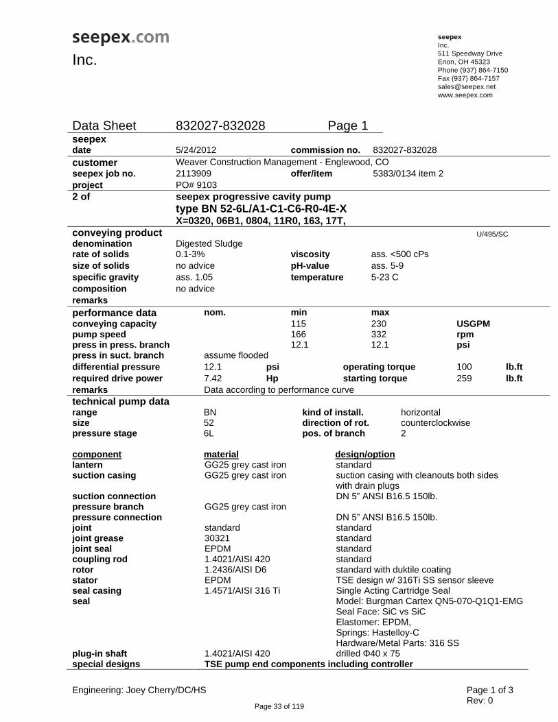
Data Sheet 832027-832028 Page 1
seepex date 5/24/2012 commission no. 832027-832028 customer Weaver Construction Management - Englewood, COseepex job no. 2113909 offer/item 5383/0134 item 2 project PO# 9103 2 of seepex progressive cavity pump type BN 52-6L/A1-C1-C6-R0-4E-X X=0320, 06B1, 0804, 11R0, 163, 17T, conveying product U/495/SCdenomination Digested Sludgerate of solids 0.1-3% viscosity ass. <500 cPs size of solids no advice pH-value ass. 5-9 specific gravity ass. 1.05 temperature 5-23 C composition no advice remarks performance data nom. min max conveying capacity 115 230 USGPM pump speed 166 332 rpm press in press. branch 12.1 12.1 psi press in suct. branch assume flooded differential pressure 12.1 psi operating torque 100 lb.ftrequired drive power 7.42 Hp starting torque 259 lb.ftremarks Data according to performance curvetechnical pump data range BN kind of install. horizontal size 52 direction of rot. counterclockwise pressure stage 6L pos. of branch 2 component material design/option lantern GG25 grey cast iron standard suction casing GG25 grey cast iron suction casing with cleanouts both sides
with drain plugs suction connection DN 5” ANSI B16.5 150lb. pressure branch GG25 grey cast iron pressure connection DN 5” ANSI B16.5 150lb. joint standard standard joint grease 30321 standard joint seal EPDM standard coupling rod 1.4021/AISI 420 standard rotor 1.2436/AISI D6 standard with duktile coating stator EPDM TSE design w/ 316Ti SS sensor sleeve seal casing 1.4571/AISI 316 Ti Single Acting Cartridge Seal seal Model: Burgman Cartex QN5-070-Q1Q1-EMG
Seal Face: SiC vs SiC Elastomer: EPDM, Springs: Hastelloy-C Hardware/Metal Parts: 316 SS
plug-in shaft 1.4021/AISI 420 drilled Φ40 x 75 special designs TSE pump end components including controller
Page 33 of 119

Engineering: Joey Cherry/DC/HS Page 2 of 3 Rev: 0
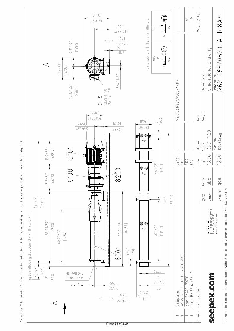
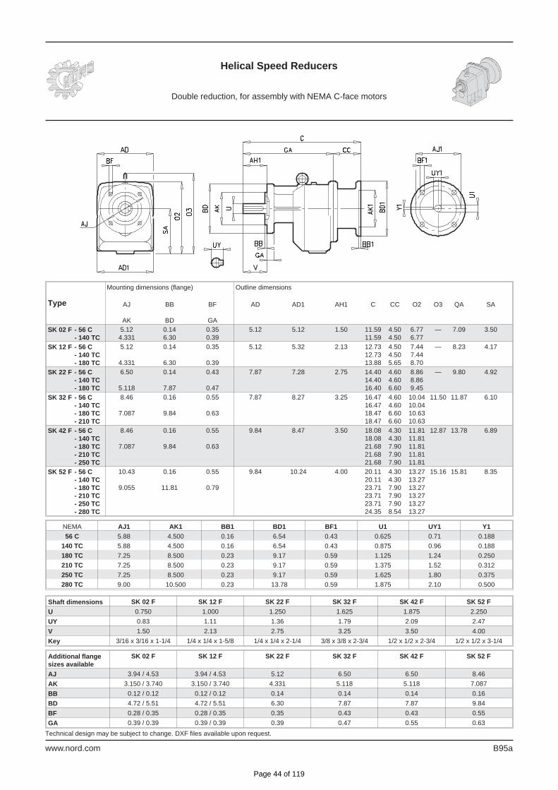
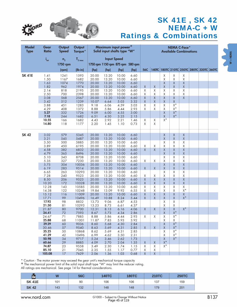
Data Sheet 832027-832028 Page 2 general operating data kind of operation continuous operation 8hr daysite of installation suitable for indoor installationremarks drive type Gear Box make Nord ratio i=5.1 model SK42ALF-250TC-NSD nom/ min - max mounting position M1(B5) output speed 346/ 166- 332 rpmflange dia 250 mm motor speed 1765/ 850- 1696 rpmoutput shaft 716/0170-002B4 frequency 60/ 29- 58 Hz special AL bearings, NSD – Nord Severe Duty electric motor manufacturer WEG model 01518ET3E254TC-W22 voltage 3x208-230/460 VAC nominal power 15 Hp rated frequency 60 Hz mounting position F1 (C-face, w/feet) enclosure TEFC starting direct on VFD thermal class F special Severe Duty, 250TC, 20:1 CT
E80- Thermostats (N.C.), E30- Space Heaters
dry running protection device model TSE – 115 VAC voltage 110-115 VAC / 50/60 Hz.delivery scope remarks TSE with NPT connections in IP55 connection head baseplate standard B-ST-LS US design material steel drawing no. 801-200/0520-A-144A3 surface painted special/accessories grout holes, 316 SS drain pan w/ drain connection and ¾” NPT drain plug
baseplate extended for motor support paint execution standard- epoxy color RAL 5013 (blue) remarks surface prep carbon steel only to SSPC SP6
surface prep all to SSPC SP1 primer - Tnemic series 37H-77 - 2 - 3.5 mil dft finish - Tnemic Series N69 Hi-Build Epoxoline II, 2 coats each 1.5 – 2.5 mil dft stainless steel components are not to be painted
packing packing type skid marking 2113909 documentation dimensional drawing no. 122738 operating manual 1 copy English sectional drawing no. 062-004_1 shaft sealing sect. view 262-0GB/0170-0-112 3 remarks additional accessories / special designs / remarks
Page 34 of 119

Engineering: Joey Cherry/DC/HS Page 3 of 3 Rev: 0
Data Sheet 832027-832028 Page 3 overpressure devices manufacturer Onyx series PSW center material CS center flange size 4” ANSI B16.5 150lbs RF end plate material derlin acetal sleeve material Buna gauge manufacturer Ashcroft series 1008 diameter 4” range 0-100 psi pressure switch manufacturer Ashcroft model B4 24 B switch type SPDT range 0-100 psi enclosure NEMA 4X set pressure 50 psi remarks Proco Flex Connection – Discharge Side (Qty 1) FA-231 150“ ANSI Drilling 350 psi max rated @150°F max Single Filled Arch csnitrile mtls 5“ x 4” x 6” Expansion Joint/Reducer w/ 150# drilled ring set & back-up flange rings Spare Parts: Rotor Stator Joint Assembly Kit Mechanical Seal Anchor Bolts: HAS – R 316SS (qty 4 per pump) QA Testing: Certificate of Compliance Per DIN EN 10204 Type 2.1 Tag: DSP-1 and DSP-2
Page 35 of 119
R
Page 36 of 119

Page 37 of 119

type constant c type constant c 0005-24 3,1076 52-6L 0,0194 0015-24 1,7972 52-6LS 0,0177 M 003-12 1,4381 52-12 0,0127 003-24 1,4229 55-6LT 0,0432 006-12 0,9558 55-12T 0,0278 006-24 0,9558 55-24 0,0157 01-48 0,5743 70-6L 0,0154 012-12 0,6144 70-6LS 0,0156 M 012-24 0,6144 70-12 0,0100 025-6L 0,4828 70-12V 0,0100 025-12T 0,6271 70-18 0,0100 05-6LT 0,6837 70-24 0,0100 025-12 0,3792 70-48 0,0100 025-24 0,3768 75-6LT 0,0344 05-12 0,2379 100-6L 0,0126 05-24 0,2306 100-6LS 1-6L 0,2379 100-18 0,0100 1-12 0,1547 110-6LT 0,0277 1-12V 0,1547 110-12T 0,0179 1-24 0,1541 130-6L 0,0099 1-24V 0,1541 130-6LS 0,0099 M 2-6L 0,1547 130-12 0,0066 2-12 0,0971 130-12V 0,0066 2-12V 0,0971 130-18 0,0067 2-24 0,0974 200-6L / 202-6L 0,0079 2-24V 0,0974 200-12T 0,0109 5-6L 0,0965 240-12 0,00455-6LS 0,0885 M 300-6L 0,0057 5-12 0,0599 300-12T 0,0082 5-12V 0,0599 5-24 0,0603 5-24V 0,0603 5-48 0,0603 8-12T 0,091 BIG sizes 10-6L 0,0597 type constant c10-6LS 0,0527 M 240-6C 0,0045 10-12 0,0379 240-9C 0,0045 10-12V 0,0379 240-12C 0,0045 10-24 0,0380 240-12L 0,0045 10-24V 0,0380 240-18L 0,0045 10-48 0,0380 240-24C 0,0044 14-12 0,0307 240-24D 0,0045 15-6LT 0,1055 300-3TR 0,0082 15-12T 0,0675 300-9TR 0,0082 17-6L 0,0379 300-12TR 0,008217-6LS 0,0362 M 300-12TU 0,0082 17-12 0,0256 300-18TU 0,0082 17-12V 0,0256 300-24TV 0,0082 17-24 0,0257 300-27TH 0,0082 17-24V 0,0257 400-3TN 0,0061 17-48 0,0257 400-6TN 0,0061 26-6L 0,0307 400-6TR 0,0061 26-12 0,0192 400-12TR 0,0061 30-6LT 0,0644 400-18TU 0,0061 30-12T 0,0452 500-3LA 0,0045 35-6L 0,0253 500-6LA 0,004535-6LS 0,0247 M 35-12 0,0155 35-12V 0,0155 35-18 0,0156 35-24 0,0156 35-24V 0,0156 35-48 0,0156 40-6LT 0,0524
Derivation of the NPSH value:
Q capacity US GPMc constant
Take NPSH value depending on the calculated factor from NPSH curve (refer to sheet 2) and add a 1,5ft safety margin.
NPSH = f (Faktor) sheet 2
Faktor = Q × c
NPSH = f (Faktor) + 1,5ft
NPSH Calculation Dokument / documentTI.122.01us
Ausgabe / issueM / 15.04.10
Blatt / sheet 1 (2)
Page 38 of 119

0,0 1,0 2,0 3,0 4,0 5,0 6,0 7,0 8,0 9,0 10,0
US Factor
0,01,02,03,04,05,06,07,08,09,0
10,011,012,013,014,015,016,017,018,019,020,021,022,023,024,025,026,027,028,029,030,031,032,033,034,035,0
NP
SH
r [ F
eet ]
NPSH Calculation Dokument / documentTI.122.01us
Ausgabe / issueM / 15.04.10
Blatt / sheet 2 (2)
Page 39 of 119

Page 40 of 119

PERFORMANCE SPECIFICATIONS Confi guration: concentric Integral motor HP (min./ max.):0.16 / 200 Integral motor kW (min./ max.):0.12 / 160 Typical effi ciency:98.5% # of gear reductions:1 to 6
MOUNTING STYLES Footed housing style:standard B5 fl ange outside diameter range [in]:4.72 to 21.65 B5 fl ange outside diameter range [mm]:120 to 550 B14 fl ange outside diameter range [in]:3.54 to 7.87 B14 fl ange outside diameter range [mm]:90 to 200 OPTIONS Custom adapter fl ange Flange pilot removed
DS1010/2007
HELICAL IN-LINEHELICAL IN-LINE
Unit Size Torque Max. Ratio Range Shaft Diameter Unit Size Torque Max. Ratio Range Shaft Diameter
[lb-in] [Nm] Min.Max. [in] [mm] [lb-in] [Nm] Min.Max. [in] [mm]
SK 02 876 99 2.95 - 73.06 0.750 20 SK 51 4,354 492 1.24 - 13.27 1.625 40SK 03 974 110 65.50 - 313.11 0.750 20 SK 52 17,912 2,024 2.78 - 86.92 2.250 55SK 11 513 58 1.35 -9.11 1.000 20 SK 53 19,753 2,232 58.94 - 728.20 2.250 55SK 12 1,628 184 2.96 - 72.63 1.000 25 SK 62 27,612 3,120 2.97 - 48.73 2.500 65SK 13 1,717 194 68.40 - 420.83 1.000 25 SK 63 32,745 3,700 17.37 - 372.21 2.500 65SK 21 681 77 1.46 - 10.20 1.250 25 SK 72 41,666 4,708 2.76 - 43.71 3.000 75SK 22 3,310 374 2.79 - 86.30 1.250 30 SK 73 50,003 5,560 18.00 - 205.61 3.000 75SK 23 3,009 340 64.80 - 516.65 1.250 30 SK 82 64,127 7,246 2.89 - 48.82 3.500 90SK 31 1,637 185 1.33 - 10.20 1.625 30 SK 83 81,243 9,180 21.04 - 216.61 3.500 90SK 32 6,284 710 2.96 - 81.27 1.625 40 SK 92 93,359 10,775 3.51 - 35.47 4.250 110SK 33 5,947 672 88.18 - 740.37 1.625 40 SK 93 123,900 14,000 19.12 - 187.89 4.250 110SK 41 2,567 290 1.41 - 14.80 1.375 35 SK 102 153,698 17,367 4.28 - 38.81 5.250 130SK 42 11,009 1,244 3.02 - 105.08 1.875 45 SK 103 204,966 23,160 21.19 - 207.47 5.250 130SK 43 11,497 1,299 40.98 - 1071.82 1.875 45
www.nord.com
RATIO AND SPEED Minimum standard ratio:1.24:1 Maximum standard ratio:13304.45:1 Minimum output speed from 1750 rpm motor:0.13 rpm Maximum output speed from 1750 rpm motor:1411 rpm
Page 41 of 119

SHAFT DATA Input and output shaft material:ASI 1045 or 4140 Input and output shaft key dimensions [in]:according to ANSI B17 Input and output shaft key dimensions [mm]:according to DIN 747 Output shaft drill and tap:standard OPTIONS Custom shaft diameters Custom spline Cross drilled holes 304 stainless steel
MOTOR MOUNTING Integral motor:1/6 to 250 HP C-face adapter frame size range:56C to 360TC IEC adapter (B5) frame size range:IEC 63 to IEC 315 Sugar scoop motor availability:56 to 365T Top mount platform motor availability:56 to 405T OPTIONS Custom motor adapter Custom coupling diameter
GEARING Quality rating on gears:up to AGMA Class 13 Minimum hardness of steel gears:58 Rockwell C Hard fi nishing of gear teeth:grinding or skive hob Drop forged gear blanks:standard Momentary overload capacity:275% Hunting tooth ratios:standard
HOUSING Typical housing material:Class 35 gray iron Machining method:single setup Main housing design:UNICASE™ one piece Seal carrier:direct to main housing Housing torsional stiffness:exceptional Housing wall section:thick Casting sealing method:dip seal
BEARINGS Bearing quality:ABEC-1 Standard output bearing:ball or spherical Heavy-duty output bearing:heavy-duty spherical
INTERNAL PARTS ASSEMBLY Assembly method:heavy press fi t Reversing duty:standard Typical backlash range [arc minutes]:10 to 17
LUBRICANT AND SEALING COMPONENTS Factory fi lled lubricant type:ISO 220 mineral oil Typical breather vent style:AUTOVENT Output seal design:QUADRILIP™ Seal System Output shaft oil seals:I double lip and 1 single lip oil seal lip material:nitrile rubber Oil seal to housing gasket:nitrile rubber OPTIONS Custom synthetic lubricating oil Custom temperature lubricating oil Fluid grease lubricant Food grade lubricating oil Long term storage preparation Magnetic drain plug Bullseye sight glass Custom drain plug Fluorinated rubber oil seal material Custom oil seals
ENVIRONMENTAL PROTECTION Exterior primer coverage:all metal exterior surfaces Paint type:Water Based Resin Paint additive:316 stainless steel fl akes USDA incidental contact exposure:H1 OPTIONS NSD+ protection • custom paint High pressure washdown IP66 oil seals:custom order Shaft seal covers:custom order
MECHANICAL VARIABLE SPEED COMPATIBILITY HP range with TITAN™ belt box:0.33 to 150 Speed range with TITAN™ belt box:8.9 to 1308 HP range with NORDISC®traction drive:0.25 to 7.5 Speed range with NORDISC®traction drive:0.5 to 1621
1002
0001
6/04
07
HELICAL IN-LINEHELICAL IN-LINE
Page 42 of 119

Engineering Information Standard Reducer Features
G1119 8 www.nord.com
S TA N DA R D R E D U C E RF E AT U R E S
> UNICASE™ one-piece housing
is torsionally stiff, machined in one
pass, has extreme accuracy, and
eliminates the split case leakage
path.
> Outside diameter of oil
seals is nitrile rubber. Direct
connection of seal to housing
eliminates bolt-on covers and
centers the seal, eliminating
the potential for leakage.
> Housing interior seal coating
locks in casting sand, fills in
processing blemishes eliminating
leak paths, and protects against
moisture damage to inside of
gear case.
> Primer paint covers all exterior
surfaces of the housing, provid-
ing excellent base corrosion
protection.
> Shaft material is wear-
resistant, high carbon steel that
provides stable non-grooving
surface for oil seal contact.
> Standard paint has 316 stain-
less steel flakes with a flexible
and tough resin binder. USDA
incidental contact H1 approval
provides excellent moisture and
corrosion resistance.
> AUTOVENT
breather seals
dirt and mois-
ture out while
allowing the gear
case to breathe during startup
and cool down.
> QUADRILIP™ shaft
seal system – con-
sisting of 2 spring
compression lips,
1 trash guard lip
and 1 collector
grease pack – keeps
contaminants out and
lubricant inside the gear case.
Labyrinth
O-Ring
SealingRing
Page 43 of 119
Helical Speed Reducers
Double reduction, for assembly with NEMA C-face motors
www.nord.com B95a
Technical design may be subject to change. DXF files available upon request.
Type
Mounting dimensions (flange) Outline dimensions
AJ
AK
BB
BD
BF
GA
AD AD1 AH1 C CC O2 O3 QA SA
SK 02 F - 56 C
- 140 TC
5.12
4.331
0.14
6.30
0.35
0.39
5.12 5.12 1.50 11.59
11.59
4.50
4.50
6.77
6.77
— 7.09 3.50
SK 12 F - 56 C
- 140 TC
- 180 TC
5.12
4.331
0.14
6.30
0.35
0.39
5.12 5.32 2.13 12.73
12.73
13.88
4.50
4.50
5.65
7.44
7.44
8.70
— 8.23 4.17
SK 22 F - 56 C
- 140 TC
- 180 TC
6.50
5.118
0.14
7.87
0.43
0.47
7.87 7.28 2.75 14.40
14.40
16.40
4.60
4.60
6.60
8.86
8.86
9.45
— 9.80 4.92
SK 32 F - 56 C
- 140 TC
- 180 TC
- 210 TC
8.46
7.087
0.16
9.84
0.55
0.63
7.87 8.27 3.25 16.47
16.47
18.47
18.47
4.60
4.60
6.60
6.60
10.04
10.04
10.63
10.63
11.50 11.87 6.10
SK 42 F - 56 C
- 140 TC
- 180 TC
- 210 TC
- 250 TC
8.46
7.087
0.16
9.84
0.55
0.63
9.84 8.47 3.50 18.08
18.08
21.68
21.68
21.68
4.30
4.30
7.90
7.90
7.90
11.81
11.81
11.81
11.81
11.81
12.87 13.78 6.89
SK 52 F - 56 C
- 140 TC
- 180 TC
- 210 TC
- 250 TC
- 280 TC
10.43
9.055
0.16
11.81
0.55
0.79
9.84 10.24 4.00 20.11
20.11
23.71
23.71
23.71
24.35
4.30
4.30
7.90
7.90
7.90
8.54
13.27
13.27
13.27
13.27
13.27
13.27
15.16 15.81 8.35
NEMA AJ1 AK1 BB1 BD1 BF1 U1 UY1 Y1
56 C 5.88 4.500 0.16 6.54 0.43 0.625 0.71 0.188
140 TC 5.88 4.500 0.16 6.54 0.43 0.875 0.96 0.188
180 TC 7.25 8.500 0.23 9.17 0.59 1.125 1.24 0.250
210 TC 7.25 8.500 0.23 9.17 0.59 1.375 1.52 0.312
250 TC 7.25 8.500 0.23 9.17 0.59 1.625 1.80 0.375
280 TC 9.00 10.500 0.23 13.78 0.59 1.875 2.10 0.500
Shaft dimensions SK 02 F SK 12 F SK 22 F SK 32 F SK 42 F SK 52 F
U 0.750 1.000 1.250 1.625 1.875 2.250
UY 0.83 1.11 1.36 1.79 2.09 2.47
V 1.50 2.13 2.75 3.25 3.50 4.00
Key 3/16 x 3/16 x 1-1/4 1/4 x 1/4 x 1-5/8 1/4 x 1/4 x 2-1/4 3/8 x 3/8 x 2-3/4 1/2 x 1/2 x 2-3/4 1/2 x 1/2 x 3-1/4
Additional flange
sizes available
SK 02 F SK 12 F SK 22 F SK 32 F SK 42 F SK 52 F
AJ 3.94 / 4.53 3.94 / 4.53 5.12 6.50 6.50 8.46
AK 3.150 / 3.740 3.150 / 3.740 4.331 5.118 5.118 7.087
BB 0.12 / 0.12 0.12 / 0.12 0.14 0.14 0.14 0.16
BD 4.72 / 5.51 4.72 / 5.51 6.30 7.87 7.87 9.84
BF 0.28 / 0.35 0.28 / 0.35 0.35 0.43 0.43 0.55
GA 0.39 / 0.39 0.39 / 0.39 0.39 0.47 0.55 0.63
Page 44 of 119
www.nord.com B137G1000 – Subject to Change Without Notice
W +
NEM
A
Model Type
Gear Ratio
Output Speed
Output Torque*
Maximum input power Solid input shafts type “W“
NEMA C-Face* Available Combinations
itot n2 T2 max Input Speed
1750 rpm 1750 rpm 1150 rpm 875 rpm 580 rpm
[rpm] [Ib-in] [hp] [hp] [hp] [hp] 56C 140TC 180TC 210TC 250TC 280TC 320TC 360TC
SK 41E 1.41 1241 1593 20.00 13.20 10.00 6.60 X X X 1.50 1167 1682 20.00 13.20 10.00 6.60 X X X 1.63 1074 1770 20.00 13.20 10.00 6.60 X X X 1.82 962 1974 20.00 13.20 10.00 6.60 X X X X X 2.14 818 2195 20.00 13.20 10.00 6.60 X X X X X 2.50 700 2398 20.00 13.20 10.00 6.60 X X X X X 3.08 568 2567 20.00 13.20 10.00 6.60 X X X X X 3.42 512 1239 10.07 6.64 5.03 3.32 X X X X 3.88 451 1283 9.18 6.06 4.59 3.03 X X X X* 4.29 408 1372 8.88 5.86 4.44 2.93 X X X X* 5.27 332 1726 9.09 6.00 4.55 3.00 X X* 7.18 244 1682 6.51 4.30 3.25 2.15 X X* 10.55 166 1682 4.43 2.92 2.21 1.46 X X X* 14.80 118 1177 2.20 1.45 1.10 0.73 X X
SK 42 3.02 579 5345 20.00 13.20 10.00 6.60 X X X 3.21 545 5487 20.00 13.20 10.00 6.60 X X X 3.50 500 5885 20.00 13.20 10.00 6.60 X X X 3.89 450 6195 20.00 13.20 10.00 6.60 X X X X X 4.58 382 6832 20.00 13.20 10.00 6.60 X X X X X 4.79 365 8496 20.00 13.20 10.00 6.60 X X X 5.10 343 8708 20.00 13.20 10.00 6.60 X X X 5.35 327 7230 20.00 13.20 10.00 6.60 X X X X X 5.75 304 10036 20.00 13.20 10.00 6.60 X X X 6.19 283 9514 20.00 13.20 10.00 6.60 X X X X X 6.65 263 10293 20.00 13.20 10.00 6.60 X X X 7.28 240 9523 20.00 13.20 10.00 6.60 X X X X X 8.50 206 9523 20.00 13.20 10.00 6.60 X X X X X 10.20 172 10328 20.00 13.20 10.00 6.60 X X X X X 12.28 143 10585 20.00 13.20 10.00 6.60 X X X X X 14.38 122 10248 19.84 13.09 9.92 6.55 X X X X X* 15.12 116 11009 20.00 13.20 10.00 6.60 X X X X X 17.71 99 10496 16.49 10.88 8.24 5.44 X X X X X* 17.92 98 8832 13.73 9.06 6.87 4.53 X X 21.50 81 10293 13.23 8.73 6.61 4.37 X X 21.87 80 9700 12.31 8.13 6.16 4.06 X X X X X* 24.41 72 7593 8.67 5.73 4.34 2.86 X X* 24.67 71 7885 8.88 5.86 4.44 2.93 X X X X* 25.88 68 11001 11.87 7.83 5.93 3.92 X X 29.29 60 9036 8.60 5.68 4.30 2.84 X X* 30.46 57 9540 8.63 5.69 4.31 2.85 X X X X* 35.25 50 10868 8.62 5.69 4.31 2.85 X X* 41.29 42 10496 6.99 4.62 3.50 2.31 X X* 50.98 34 9717 5.24 3.46 2.62 1.73 X X* 60.66 29 8885 4.09 2.70 2.04 1.35 X X X* 74.87 23 9558 3.49 2.30 1.74 1.15 X X X* 85.10 21 7045 2.35 1.55 1.17 0.77 X X 105.08 17 7629 2.06 1.36 1.03 0.68 X X
W 56C 140TC 180TC 210TC 250TC
SK 41E 101 90 106 106 137 159
SK 42 143 132 148 148 179 201
lb
SK 41E , SK 42NEMA-C + W
Ratings & Combinations
* Caution - The motor power may exceed the gear unit’s mechanical torque capacity The mechanical power limit of the solid input shaft type “W” may limit the reducer rating.All ratings are mechanical. See page 14 for thermal considerations.
Page 45 of 119

BIM 1012/2005/03 7 www.nord.com
PARTS LIST
RECOMMENDED SPARE PARTSBearings – all
Seals – all Gaskets – all
Seal Plugs – all Shims – all
IMPORTANT! When ordering parts, it is necessary to have the NORD SERIAL NUMBER from the unit the parts are for. The serial number will dictate the correct parts for that particular unit. The gearbox nameplate will have the serial number on it.
12355a678910111214151617181920212223242526273031325253545556575859606162636465666869707174
900901902904905906907908909910911914916918924925929932938939940941942943947948949950
Output shaftKeyShaft sealOutput shaft bearing, normalOutput shaft bearing, reinforcedOutput shaft bearingSealVent screwShimDriven gearKeyCirclipDriving pinionGear casePinion shaft bearingDriven pinionKeyDriving gearSealPlugGear case coverPinion shaft bearingShimHexagon boltWasherSpiral pinSealShimSealSpiral pinSpiral pinIntermediate shaft, gearcutHexagon boltWasherSealSealPlugIntermediate shaft, plainGrooved ball bearingGrooved ball bearingKeyShimDriving gearDriving pinionGear case 3rd.-red.Gear case coverHexagon boltWasherSeal
Rotor with shaft, plainRotor with shaft, gearcutEnd shield AShaft sealBearing ABearing shimTerminal box frameTerminal box coverTerminal box frame gasketTerminal box cover gasketTerminal boardcable entry glandStator caseKeyCollar boltHexagonal nutBearing BEnd shield BSecond motor shaft endFanFan coverKeyCirclipKeyCirclipCirclipOval flat-head boltOval flat-head bolt
II
I
Page 46 of 119

www.nord.com A42
INTRO
DU
CTION
G1000 – Subject to Change Without Notice
Lubrication
Lubrication TypesProper gearbox lubrication is essential in order to reduce friction, heat, and component wear. Lubricants reduce heat and wear by inserting a protective “fl uid boundary” between mating parts and preventing direct metal to metal con-tact. Lubricants also help prevent corrosion and oxidation, minimize foam, improve heat transfer, optimize reducer effi ciency, absorb shock loads and reduce noise.
Mounting position not only determines the proper fi ll-level but may also have some effect on fi nal reducer assembly. If considering any mounting positions that are not shown as catalog-standard options, it is critical that the customer consult with NORD prior to ordering. Unless otherwise specifi ed, NORD supplies most all gear units (*) factory-fi lled with the standard lubrication type and the appropriate amount of lubricating oil.
* Gear units SK10282, SK10382, SK11282, SK11382, SK12382, and SK9096.1 are supplied without oil.
Standard Oil Lubricants
Gear Unit Type Ambient Temperature Oil Type ISO Viscosity Manufacturer Brand / Type
Helical-Inline, Parallel-Shaft, & Helical-Bevel
-4 to 104 °F (-20 to 40 °C) MIN-EP VG 220 Shell / Omala 220 -40 to 140 °F (-40 to 60 °C) PAO VG 220 Mobil SHC 630 23 to 104 °F (-5 to 40 °C) FG VG 220 Shell / FM 220
Helical-Worm -22 to 122 °F (-30 to 50 °C) PAO VG 680 Mobil SHC 636
Optional Oil LubricantsGear Unit Type Ambient Temperature Oil Type ISO Viscosity Manufacturer Brand / Type
Helical-Inline, Parallel-Shaft, & Helical-Bevel
-31 to 176 °F (-35 to 80 °C) PAO VG 460 Mobil SHC 634-40 to 77 °F (-40 to 25 °C) PAO VG 150 Mobil SHC 629-40 to 140 °F (-40 to 60 °C) FG-PAO VG 220 Shell / Cassida GL 220
Helical-Worm -40 to 122 °F (-40 to 50 °C) FG-PAO VG 460 Shell / Cassida GL 460
Standard Bearing Grease LubricantsGrease Type / Thickener Ambient Temperature NLGI Grade Manufacturer Brand / Type
Standard (Li-Complex) -22 to 140 °F (-30 to 60 °C) NLGI 2 Shell Albida EP LC2 High Temp (Polyurea) -13 to 176 °F (-25 to 80 °C) NLGI 2 Mobil Polyrex EP 2 Food-Grade (Al-Complex) -13 to 104 °F (-25 to 40 °C) NLGI 2 Mobil Grease FM 222
Stocked Lubricant
Oil Formulation Codes
MIN-EP Mineral Oil with EP Additive
PAO Synthetic Polyalphaolefi n Oil
PG Synthetic Polyglycol Oil
FG Food-Grade Oil
FG-PAO Food-Grade, Synthetic Polyalphaolefi n Oil
Important Notes
• In worm gears avoid using (EP) gear oils that contain sulfur-phosphorous chemistries, as these additives can react adversely with bronze worm gears and accelerate wear.• Food grade lubricants must be in compliance with FDA 212 CFR 178.3570 and qualify as a NSF-H1 lubricant. Please consult with lubrication manufacture for more information. • When making a lubrication change, check with the lubrication supplier to assure compatibility and to obtain recommended cleaning or fl ushing procedures. • Do not mix different oils with different additive packages or different base oil formulation types. Polyglycol (PG) oils are not miscible with other oil types and should never be mixed with mineral oil, or Polyalphaolefi n (PAO) oil. • Please Consult NORD if considering cold-temperature oils below an ISO Viscosity VG100 or lower.
Page 47 of 119

www.nord.com A44
INTRO
DU
CTION
G1000 – Subject to Change Without Notice
In-line Foot Mount Positions & Oil Fill Quantities
M6
M1
M2
M4M5
M3
MountingPosition M1 M2 M3 M4 M5 M6
Quarts Liters Quarts Liters Quarts Liters Quarts Liters Quarts Liters Quarts LitersSK02 0.16 0.15 0.63 0.60 0.74 0.70 0.63 0.60 0.42 0.40 0.42 0.40SK03 0.32 0.30 1.06 1.00 0.85 0.80 0.95 0.90 0.63 0.60 0.63 0.60SK11E 0.26 0.25 0.53 0.50 0.58 0.55 0.42 0.40 0.37 0.35 0.37 0.35SK12 0.26 0.25 0.79 0.75 0.90 0.85 0.79 0.75 0.53 0.50 0.53 0.50SK13 0.63 0.60 1.32 1.25 1.16 1.10 1.27 1.20 0.74 0.70 0.74 0.70SK21E 0.63 0.60 1.27 1.20 1.27 1.20 1.06 1.00 1.06 1.00 1.06 1.00SK22 0.53 0.50 1.90 1.80 2.11 2.00 1.90 1.80 1.43 1.35 1.43 1.35SK23 1.37 1.30 2.54 2.40 2.43 2.30 2.48 2.35 1.69 1.60 1.69 1.60SK31E 1.16 1.10 2.85 2.70 2.33 2.20 2.43 2.30 1.80 1.70 1.80 1.70SK32 0.95 0.90 2.64 2.50 3.17 3.00 3.07 2.90 2.11 2.00 2.11 2.00SK33N 1.69 1.60 3.07 2.90 3.38 3.20 3.91 3.70 2.43 2.30 2.43 2.30SK41E 1.80 1.70 2.75 2.60 3.49 3.30 2.64 2.50 2.75 2.60 2.75 2.60SK42 1.37 1.30 4.76 4.50 4.76 4.50 4.55 4.30 3.38 3.20 3.38 3.20SK43 3.17 3.00 5.92 5.60 5.50 5.20 6.98 6.60 3.81 3.60 3.81 3.60SK51E 2.33 2.20 4.65 4.40 4.97 4.70 4.23 4.00 3.59 3.40 3.59 3.40SK52 2.64 2.50 7.40 7.00 7.19 6.80 7.19 6.80 5.39 5.10 5.39 5.10SK53 4.76 4.50 9.20 8.70 8.14 7.70 9.20 8.70 6.34 6.00 6.34 6.00SK62 6.87 6.50 15.9 15.0 13.7 13.0 16.9 16.0 15.9 15.0 15.9 15.0SK63 13.7 13.0 15.3 14.5 15.3 14.5 16.9 16.0 13.7 13.0 13.7 13.0SK72 10.6 10.0 24.3 23.0 19.0 18.0 27.5 26.0 24.3 23.0 24.3 23.0SK73 21.7 20.5 21.1 20.0 23.8 22.5 28.5 27.0 21.1 20.0 21.1 20.0SK82 14.8 14.0 37.0 35.0 28.5 27.0 46.5 44.0 33.8 32.0 33.8 32.0SK83 31.7 30.0 32.8 31.0 35.9 34.0 39.1 37.0 34.9 33.0 34.9 33.0SK92 26.4 25.0 77.1 73.0 49.7 47.0 80.3 76.0 55.0 52.0 55.0 52.0SK93 56.0 53.0 74.0 70.0 62.4 59.0 76.1 72.0 51.8 49.0 51.8 49.0SK102 38.1 36.0 83.5 79.0 69.8 66.0 107.8 102 75.1 71.0 75.1 71.0SK103 78.2 74.0 75.1 71.0 78.2 74.0 102.5 97.0 70.8 67.0 70.8 67.0
Page 48 of 119

www.nord.com H750
SERVICE
G1000 – Subject to Change Without Notice
M1B3/B5
M1B3/B5
M1B3/B5
M1B3/B5
M2V6/V3
M5B6/B5II
M4V5/V1
M3B8/B5I
M6B7/B5III
M2V6/V3
M5B6/B5II
M3B8/B5I
M4V5/V1
M6B7/B5III
M2V6/V3
M2V6/V3
M5B6/B5II M5
B6/B5II
M3B8/B5I
M3B8/B5I
M4V5/V1 M4
V5/V1
M6B7/B5III
M6B7/B5III
SK 11ESK 21ESK 31ESK 41ESK 51E
SK 02SK 12SK 22SK 32SK 42SK 52
SK 03SK 13SK 23SK 33NSK 43SK 53
SK 62SK 72SK 82SK 92SK 102SK 63*SK 73*SK 83*SK 93*SK 103*
*
*
= Vent = Oil Level = Oil Drain
Oil Plugs
Page 49 of 119

www.nord.com A77G1000 – Subject to Change Without Notice
INTR
OD
UCT
ION
Helical In-lineWeights - Reducer
Approximate Weights [lb]
Type W 56C 140TC 180TC 210TC 250TC 280TC 320TC 360TC
SK 02 26 44 44 – – – – – –SK 03 35 – – – – – – – –
SK 11 35 35 49 – – – – – –SK 12 48 48 57 – – – – – –SK 13 46 – – – – – – – –SK 12/02 49 49 – – – – – – –
SK 21 49 46 46 59 – – – – –SK 22 64 73 73 77 – – – – –SK 23 68 86 86 – – – – – –SK 22/02 77 93 93 – – – – – –
SK 31 59 62 62 66 – – – – –SK 32 88 90 90 95 – – – – –SK 33 N 95 103 103 – – – – –SK 32/12 106 115 115 132 – – – – –
SK 41 101 91 88 92 130 159 – – –SK 42 143 138 132 143 174 201 – – –SK 43 154 152 152 156 – – – – –SK 42/12 143 148 148 170 – – – – –
SK 51 121 105 105 117 147 150 199 – –SK 52 207 169 169 174 205 207 285 – –SK 53 227 185 185 189 – – – – –SK 52/12 207 179 179 234 – – – – –
SK 62 377 – – 317 354 392 392 567 567SK 63 328 295 288 299 330 332 405 – –SK 63/22 348 329 329 333 – – – – –SK 63/23 353 335 335 – – – – – –
SK 72 529 440 477 515 515 721 721SK 73 551 416 453 491 491 743 743SK 73/22 527 452 452 456 – – – – –SK 73/32 551 553 553 558 571 – – – –
SK 82 880 – – 666 702 741 741 962 962SK 83 787 – – 631 669 706 706 979 979SK 83/32 787 723 723 728 741 – – – –SK 83/42 842 837 837 848 879 906 – – –
SK 92 1268 – – – – 1215 1215 1350 1350SK 93 1182 – – 1184 1184 1239 1239 1374 1374SK 93/42 1237 1226 1226 1272 1272 1294 – – –SK 93/52 1301 – – 1276 1306 1308 1308 – –
SK 102 1821 – – – – – 1702 1837 1837SK 103 1775 – – 1667 1667 1722 1722 1857 1857SK 103/52 1784 1773 1773 1819 1819 1840 1860 – –
Above weights are approximate. Depending upon ratio, oil quantity and optional equipment, reducer weights may be different than shown.Exact weights can be obtained after the unit is fully asembled.
lb
Page 50 of 119
No.:
Date: 30-MAY-2012
TECHNICAL PROPOSAL
Three-phase induction motor - Squirrel cage rotor
Customer :
Product line : W22 NEMA Premium - Ball Bearings
Catalog Number : 01518ET3E254TC-W22List Price :
Notes:
Performed by: Checked:
Page 51 of 119

No.:
Date: 30-MAY-2012
DATA SHEETThree-phase induction motor - Squirrel cage rotor
Customer : Product line : W22 NEMA Premium - Ball Bearings
Frame : 254TOutput : 15 HPFrequency : 60 HzPoles : 4Full load speed : 1765Slip : 1.94 %Voltage : 208-230/460 VRated current : 39.8-36.0/18.0 ALocked rotor current : 234/117 ALocked rotor current (Il/In) : 6.5No-load current : 16.0/8.00 AFull load torque : 44.0 lb.ftLocked rotor torque : 230 %Breakdown torque : 270 %Design : BInsulation class : FTemperature rise : 80 KLocked rotor time : 17 s (hot)Service factor : 1.25Duty cycle : S1Ambient temperature : -20°C - +40°CAltitude : 1000Degree of Protection : IP55Approximate weight : 251 lbMoment of inertia : 2.6198 sq.ft.lbNoise level : 64 dB(A)
D.E. N.D.E. Load Power factor Efficiency (%)Bearings 6309 C3 6209 C3 100% 0.83 92.4Regreasing interval 20000 h 20000 h 75% 0.78 91.7Grease amount 13 g 9 g 50% 0.68 91.0
Notes:
Performed by Checked
Page 52 of 119

Percent of rated output (%)
A - E
ffici
ency
(%)
B - P
ower
fact
or
C - Slip
D - C
urrent at 230V (A)
0 10 20 30 40 50 60 70 80 90 100 110 120 130
40
50
60
70
80
90
100
0.4
0.5
0.6
0.7
0.8
0.9
1.0 0.0
1.0
2.0
3.0
4.0
5.0
0
10
20
30
40
A
B
C
D
No.:
Date: 30-MAY-2012
PERFORMANCE CURVES RELATED TO RATED OUTPUTThree-phase induction motor - Squirrel cage rotor
Customer : Product line : W22 NEMA Premium - Ball Bearings
Frame : 254TOutput : 15 HPFrequency : 60 HzFull load speed : 1765Voltage : 208-230/460 VRated current : 39.8-36.0/18.0 AInsulation class : F
Locked rotor current (Il/In) : 6.5Duty cycle : S1Service factor : 1.25Design : BLocked rotor torque : 230 %Breakdown torque : 270 %
Notes:
Performed by Checked
Page 53 of 119

0.0
0.5
1.0
1.5
2.0
2.5
3.0
3.5
4.0
4.5
5.0
A
0.0
1.0
2.0
3.0
4.0
5.0
6.0
7.0
8.0
9.0
10.0
B
0 10 20 30 40 50 60 70 80 90 100Speed related to rated speed (%)
A - T
orqu
e re
late
d to
rate
d to
rque
(C/C
n)
B - Current related to rated current (I/In)
No.:
Date: 30-MAY-2012
CHARACTERISTIC CURVES RELATED TO SPEEDThree-phase induction motor - Squirrel cage rotor
Customer : Product line : W22 NEMA Premium - Ball Bearings
Frame : 254TOutput : 15 HPFrequency : 60 HzFull load speed : 1765Voltage : 208-230/460 VRated current : 39.8-36.0/18.0 AInsulation class : F
Locked rotor current (Il/In) : 6.5Duty cycle : S1Service factor : 1.25Design : BLocked rotor torque : 230 %Breakdown torque : 270 %
Notes:
Performed by Checked
Page 54 of 119

12
34
56
78
A B C D E F
30-M
AY-2
012
Thre
e-ph
ase
indu
ctio
n m
otor
Fram
e 2
54T
- IP5
5
Not
es:
Perfo
rmed
by:
Che
cked
:
Cus
tom
er:
W22
NEM
A Pr
emiu
m -
Ball
Bear
ings
2E10
.000
J2.
539
A12
.126
P12
.953
AB10
.394
2F 8.25
2K
2.55
9B
10.0
00BA 4.25
0U
1.62
5N
-W4.
000
ES 2.75
6S
0.37
5R
1.40
6de
pth
0.37
5D
6.25
0G
0.82
7H
B3.
061
O12
.598
T2.
087
HF
6.56
5H
H8.
376
HK
3.93
7H
0.53
1C
23.2
13LL 7.79
5LM 7.40
2AA
NPT
1 1
/2"
d1 A 4
d2 A 4
Flan
geFC
-184
AJ 7.25
0AK 8.50
0BD 8.87
5BF
UN
C 1
/2"x
13BB 0.25
0BC 0.25
0AH 3.75
0
Page 55 of 119

www.weg.net
W22 Electric Motor 15
10. Motor protections
Protections available for W22 can be classified as follows:g Based on operating temperatureg Based on operating current.
In section 12 - Construction features it is possible to identify the type of protection for each W22 line.
Table 11 – Power and quantity of space heaters
Frame Quantities Total power rated (W)
143 to 145 1 11
182 to 184 2 22
213 to 256 2 30
284 to 326 2 38
364/5 to 404/5 2 56
444/5 to 504/5 2 140
586/7 to 588/9 2 174
10.1 Protection based on operating temperatureContinuous duty motors must be protected from overload either by a device integrated into the motor winding or via an independent protection system, usually a thermal relay with rated or setting current, equal to or below the value obtained when multiplying the power supply rated current (In), as per table 12.
Service Factor Relay setting current
1.0 up to 1.15 In x S.F.
≥ 1.15 (In x S.F.) – 5%
Table 12 – Relay setting current referred to service factor
Figure 26 - RTD
RTD
They are also fitted with calibrated resistances that vary linearly with temperature, allowing continuous reading of motor operating temperature through a monitoring display, with high precision rate and response sensitivity. The same detector can serve as alarm (with operation above the regular operating temperature) and trip (usually set up for the maximum temperature of the insulation class).
Thermistor (PTC)
These are thermal protectors consisting of semiconductordetectors with sudden variation of the resistance whenreaching a certain temperature (figure 27).
PTC is considered a thermistor with the resistance increasing drastically to a well defined temperature figure. This sudden resistance variation blocks the PTC current, causing the output relay to operate, and the main circuit to switch-off.The thermistors are of small dimensions, do not wear and have quicker response if compared to other protectors, although they do not allow continuous monitoring of motor operating temperature.Together with their electronic circuits, these thermistors provide full protection against overheating caused by overload, under or overvoltage or frequent reversing operations.Where thermistor protection is required to provide both alarm and trip operation, it is necessary for each phase of the motor winding to be equipped with two sets of appropriately rated thermistors.WEG Automation has a product called RPW which is an electronic relay intended specifically to read the PTC signal and operate its output relay. For more information go to the website www.weg.net.
Thermostats
These are silver-contact thermal sensors, normally closed, that operate at certain temperature rise. When their operating temperature decreases, they go back to the original position instantaneously, allowing the silver contact to close again.The thermostats are series-connected with the contactor coil, and can be used either as alarm or trip.
There are also other types of thermal protectors such as PT-1000, KTY and thermocouples. Contact your local WEG office closest to you for more information.
10.2 Protection based on operating currentOverloads are processes that usually make the temperature increase gradually. To solve this problem, the thermal protectors described in item 10.1 are quite suitable. However, the only way to protect motors against short-circuit currents is the application of fuses. This type of protection depends directly on the current and it is highly effective in cases of locked rotor.WEG Automation supplies fuses in versions D and NH. Go to the site www.weg.net for more information.
These are temperature detectors (figure 26) with operating principle based on the properties that some materials vary the electric resistance with the variation in temperature (usually platinum, nickel or copper).
Figure 27 – Thermistor (PTC)
greater than 95%, regardless of the operating schedule. It should be highligthed that in this situation it is strongly recommended that an epoxy paint known as internal anti-corrosive painting is applied in the internal components of the motor.
More information can be obtained in section 7.3.
For all frame sizes, W22 motors can be provided with space heaters suitable for 110-127 V, 220-240 V and 380-480 V. Motors in frame sizes 586/7T and 588/9T are supplied with space heaters for 220-240 V as standard. As an option, dual voltage heaters of 110-127 / 220-240 V can be supplied for frame sizes 182T to 588/9T.The power rating and number of space heaters fitted depends on the size of the motor as indicated in table 11 below:
Page 56 of 119

Page 57 of 119
WED-002
INSTALATION OF SPACE HEATERS IN INDUCTION MOTORS
Page 1 of 2 Source: WEG / TOP - 0137
NORM Rev. 00 06/01/2004
Company: WEM Origin:
Edited by: Valone Gomes
1. OBJECTIVE: This standard aims at providing specification and installation procedures for “space-heater” installed in WEG motors.
2. WATTAGE AND CONNECTIONS:
SPACE HEATER VOLTAGE FRAMES
110 ± 22V 220 ± 44V 440 ± 88V NEMA IEC
TOTAL WATTS
(W ± 10%) 3) TYPE CONNECTION/Req. TYPE CONNECTION/Req. TYPE CONNECTION/Req.
63 71 80
143 145 90
81) 20W/m-110V
Req. = 1,512 Ώ
20W/m-220V
Req. = 6,050Ώ
20W/m-440V
Req.=12,100Ώ 100
182 184 112
162) 20W/m-110V
Req. = 756Ώ
20W/m-220V
Req. = 3,025Ώ
20W/m-440V
Req. = 6,050Ώ
213 215 132 24 30W/m-
110V
Req.= 504Ώ
30W/m-220V
Req. = 2,017Ώ
30W/m-440V
Req. = 8,067Ώ 254 256 160
284 286 180
324 326 200
48 30W/m-
110V
Req. = 252Ώ
30W/m-220V
Req. = 1,008.5Ώ
30W/m-440V
Req = 40,033.5 Ώ
364 365 225
404 405 250
79 35W/m-110V
Req.= 153Ώ
35W/m-220V
Req. = 612Ώ
35W/m-
440V
Req.=2,450Ώ 444 445 280
447 449
504/5 315
5008 315B
586/7 355
158
35W/m-110V
Req. = 76.5Ώ
35W/m-220V
Req. = 306Ώ
35W/m-440V
Req. = 1,225Ώ
Page 58 of 119

WED-002
INSTALATION OF SPACE HEATERS IN INDUCTION MOTORS
Page 2 of 2 Source: WEG / TOP - 0137
NORM Rev. 00 06/01/2004
Company: WEM Origin:
Edited by: Valone Gomes
Note: 1) For voltage of 440V, the total power is = 16W. 2) For voltage of 440V, the total power is = 32W.
3) The total Space Heather Watts is calculated according to: Wq
VP
Re
2
3. SPACE HEATER INSTALLATION 3.1. Space Heater is installed on the stator-winding head (at the opposite side of the leads) before the stator is pressed into the frame. On frame 364 and above, the space heater is installed into the stator-winding head (same side of the leads) after the winding head has been pressed. 3.2. Space Heather is fasten at, minimum, 4 points by nylon cord. For frames 364 and above it is fastened with a polyester jacket. Notes:
1) Space heater installation does not require varnish impregnation. 2) Space heater leads are identified by:
- R1 for the first space heater and - R2 for the second space heater (when installed).
Space Heater Leads
Stator lamination
Winding
Space Heater
Page 59 of 119

Tab 3 Pump Technical Data: BN 35-6L
Page 60 of 119

Inc.
seepex Inc. 511 Speedway Drive Enon, OH 45323 Phone (937) 864-7150 Fax (937) 864-7157 [email protected] www.seepex.com
Engineering: Joey Cherry/DC/HS Page 1 of 3 Rev: 0
Data Sheet 832029-832030 Page 1
seepex date 5/24/2012 commission no. 832029-832030 customer Weaver Construction Management - Englewood, COseepex job no. 2113909 offer/item 5383/0134 item 1 project PO# 9103 2 of seepex progressive cavity pump type BN 35-6L/A1-C1-C6-R0-4E-X X=0320, 06B1, 0804, 11R0, 163, 17T, conveying product U/495/SCdenomination Scum rate of solids 0.1-3% viscosity ass. <500 cPs size of solids no advice pH-value ass. 5-9 specific gravity ass. 1.05 temperature 5-23 C composition no advice remarks performance data nom. min max conveying capacity 47 94 USGPM pump speed 104 206 rpm press in press. branch 6.7 6.7 psi press in suct. branch assume flooded differential pressure 6.7 psi operating torque 63 lb.ftrequired drive power 3.16 Hp starting torque 185 lb.ftremarks Data according to performance curvetechnical pump data range BN kind of install. horizontal size 35 direction of rot. counterclockwise pressure stage 6L pos. of branch 2 component material design/option lantern GG25 grey cast iron standard suction casing GG25 grey cast iron suction casing with cleanouts both sides
and drain plug suction connection DN 5" ANSI B16.5 150lb. pressure branch GG25 grey cast iron pressure connection DN 4" ANSI B16.5 150lb. joint standard standard joint grease 30321 standard joint seal EPDM standard coupling rod 1.4021/AISI 420 standard rotor 1.2436/AISI D6 standard with duktile coating stator EPDM TSE design w/ 316Ti SS sensor sleeve seal casing 1.4571/AISI 316 Ti Single Acting Cartridge Seal seal Model: Burgman Cartex QN5-070-Q1Q1-EMG
Seal Face: SiC vs SiC Elastomer: EPDM, Springs: Hastelloy-C Hardware/Metal Parts: 316 SS
plug-in shaft 1.4021/AISI 420 drilled Φ40 x 75 special designs TSE pump end components including controller
Page 61 of 119

Engineering: Joey Cherry/DC/HS Page 2 of 3 Rev: 0
Data Sheet 832029-832030 Page 2 general operating data kind of operation continuous operation 8hr daysite of installation suitable for indoor installationremarks drive type GearBox make Nord ratio i=8.5 model SK42ALF-180TC- NSD nom/ min - max mounting position M1(B5) output speed 206/ 104- 206 rpmflange dia 250 mm motor speed 1755/ 891- 1755 rpmoutput shaft 716/0170-002B4 frequency 60/ 30- 60 Hz special AL bearings, NSD – Nord Severe Duty electric motor manufacturer WEG model 00518ET3E184TC-W22 voltage 3x208-230/460 VAC nominal power 5 Hp rated frequency 60 Hz mounting position F1 (C-face, footed) enclosure TEFC starting direct on FVNR thermal class F special Severe Duty, 184TC, 20:1 CT
E80- Thermostats(N.C.), E30- Space Heaters
dry running protection device model TSE – 115 VAC voltage 110-115 VAC / 50/60 Hz.delivery scope remarks TSE with NPT connections in IP55 connection head baseplate standard B-ST-LS US design material steel drawing no. 801-200/0170-C-155A3 surface painted special/accessories grout holes, 316 SS drain pan w/drain connection and ¾” NPT drain plug
baseplate extended for motor support paint execution standard- epoxy color RAL 5013 (blue) remarks surface prep carbon steel only to SSPC SP6
surface prep all to SSPC SP1 primer - Tnemic series 37H-77 - 2 - 3.5 mil dft finish - Tnemic Series N69 Hi-Build Epoxoline II, 2 coats each 1.5 – 2.5 mil dft stainless steel components are not to be painted
packing packing type skid marking 2113909 documentation dimensional drawing no. 122742 operating manual 1 copy English sectional drawing no. 062-004_1 shaft sealing sect. view 262-0GB/0170-0-112 3 remarks additional accessories / special designs / remarks
Page 62 of 119

Engineering: Joey Cherry/DC/HS Page 3 of 3 Rev: 0
Data Sheet 832029-832030 Page 3 overpressure devices manufacturer Onyx series PSW center material CS center flange size 4” ANSI B16.5 150lbs RF end plate material derlin acetal sleeve material Buna gauge manufacturer Ashcroft series 1008 diameter 4” range 0-100 psi pressure switch manufacturer Ashcroft model B4 24 B switch type SPDT range 0-100 psi enclosure NEMA 4X set pressure 50 psi remarks Proco Flex Connection – Discharge Side (Qty 1) FA-231 150“ ANS Drilling 350 psi max rated @150°F max Single Filled Arch csnitrile mtls 4“ x 4” x 6” Expansion Joint w/ 100# drilled ring set & back-up flange rings Spare Parts: Rotor Stator Joint Assembly Kit Mechanical Seal Anchor Bolts: HAS – R 316SS (qty 4 per pump) QA Testing: Certificate of Compliance Per DIN EN 10204 Type 2.1 Tag: SCP-1 and SCP-2
Page 63 of 119

Page 64 of 119
Page 65 of 119

type constant c type constant c 0005-24 3,1076 52-6L 0,0194 0015-24 1,7972 52-6LS 0,0177 M 003-12 1,4381 52-12 0,0127 003-24 1,4229 55-6LT 0,0432 006-12 0,9558 55-12T 0,0278 006-24 0,9558 55-24 0,0157 01-48 0,5743 70-6L 0,0154 012-12 0,6144 70-6LS 0,0156 M 012-24 0,6144 70-12 0,0100 025-6L 0,4828 70-12V 0,0100 025-12T 0,6271 70-18 0,0100 05-6LT 0,6837 70-24 0,0100 025-12 0,3792 70-48 0,0100 025-24 0,3768 75-6LT 0,0344 05-12 0,2379 100-6L 0,0126 05-24 0,2306 100-6LS 1-6L 0,2379 100-18 0,0100 1-12 0,1547 110-6LT 0,0277 1-12V 0,1547 110-12T 0,0179 1-24 0,1541 130-6L 0,0099 1-24V 0,1541 130-6LS 0,0099 M 2-6L 0,1547 130-12 0,0066 2-12 0,0971 130-12V 0,0066 2-12V 0,0971 130-18 0,0067 2-24 0,0974 200-6L / 202-6L 0,0079 2-24V 0,0974 200-12T 0,0109 5-6L 0,0965 240-12 0,00455-6LS 0,0885 M 300-6L 0,0057 5-12 0,0599 300-12T 0,0082 5-12V 0,0599 5-24 0,0603 5-24V 0,0603 5-48 0,0603 8-12T 0,091 BIG sizes 10-6L 0,0597 type constant c10-6LS 0,0527 M 240-6C 0,0045 10-12 0,0379 240-9C 0,0045 10-12V 0,0379 240-12C 0,0045 10-24 0,0380 240-12L 0,0045 10-24V 0,0380 240-18L 0,0045 10-48 0,0380 240-24C 0,0044 14-12 0,0307 240-24D 0,0045 15-6LT 0,1055 300-3TR 0,0082 15-12T 0,0675 300-9TR 0,0082 17-6L 0,0379 300-12TR 0,008217-6LS 0,0362 M 300-12TU 0,0082 17-12 0,0256 300-18TU 0,0082 17-12V 0,0256 300-24TV 0,0082 17-24 0,0257 300-27TH 0,0082 17-24V 0,0257 400-3TN 0,0061 17-48 0,0257 400-6TN 0,0061 26-6L 0,0307 400-6TR 0,0061 26-12 0,0192 400-12TR 0,0061 30-6LT 0,0644 400-18TU 0,0061 30-12T 0,0452 500-3LA 0,0045 35-6L 0,0253 500-6LA 0,004535-6LS 0,0247 M 35-12 0,0155 35-12V 0,0155 35-18 0,0156 35-24 0,0156 35-24V 0,0156 35-48 0,0156 40-6LT 0,0524
Derivation of the NPSH value:
Q capacity US GPMc constant
Take NPSH value depending on the calculated factor from NPSH curve (refer to sheet 2) and add a 1,5ft safety margin.
NPSH = f (Faktor) sheet 2
Faktor = Q × c
NPSH = f (Faktor) + 1,5ft
NPSH Calculation Dokument / documentTI.122.01us
Ausgabe / issueM / 15.04.10
Blatt / sheet 1 (2)
Page 66 of 119

0,0 1,0 2,0 3,0 4,0 5,0 6,0 7,0 8,0 9,0 10,0
US Factor
0,01,02,03,04,05,06,07,08,09,0
10,011,012,013,014,015,016,017,018,019,020,021,022,023,024,025,026,027,028,029,030,031,032,033,034,035,0
NP
SH
r [ F
eet ]
NPSH Calculation Dokument / documentTI.122.01us
Ausgabe / issueM / 15.04.10
Blatt / sheet 2 (2)
Page 67 of 119
PERFORMANCE SPECIFICATIONS Confi guration: concentric Integral motor HP (min./ max.):0.16 / 200 Integral motor kW (min./ max.):0.12 / 160 Typical effi ciency:98.5% # of gear reductions:1 to 6
MOUNTING STYLES Footed housing style:standard B5 fl ange outside diameter range [in]:4.72 to 21.65 B5 fl ange outside diameter range [mm]:120 to 550 B14 fl ange outside diameter range [in]:3.54 to 7.87 B14 fl ange outside diameter range [mm]:90 to 200 OPTIONS Custom adapter fl ange Flange pilot removed
DS1010/2007
HELICAL IN-LINEHELICAL IN-LINE
Unit Size Torque Max. Ratio Range Shaft Diameter Unit Size Torque Max. Ratio Range Shaft Diameter
[lb-in] [Nm] Min.Max. [in] [mm] [lb-in] [Nm] Min.Max. [in] [mm]
SK 02 876 99 2.95 - 73.06 0.750 20 SK 51 4,354 492 1.24 - 13.27 1.625 40SK 03 974 110 65.50 - 313.11 0.750 20 SK 52 17,912 2,024 2.78 - 86.92 2.250 55SK 11 513 58 1.35 -9.11 1.000 20 SK 53 19,753 2,232 58.94 - 728.20 2.250 55SK 12 1,628 184 2.96 - 72.63 1.000 25 SK 62 27,612 3,120 2.97 - 48.73 2.500 65SK 13 1,717 194 68.40 - 420.83 1.000 25 SK 63 32,745 3,700 17.37 - 372.21 2.500 65SK 21 681 77 1.46 - 10.20 1.250 25 SK 72 41,666 4,708 2.76 - 43.71 3.000 75SK 22 3,310 374 2.79 - 86.30 1.250 30 SK 73 50,003 5,560 18.00 - 205.61 3.000 75SK 23 3,009 340 64.80 - 516.65 1.250 30 SK 82 64,127 7,246 2.89 - 48.82 3.500 90SK 31 1,637 185 1.33 - 10.20 1.625 30 SK 83 81,243 9,180 21.04 - 216.61 3.500 90SK 32 6,284 710 2.96 - 81.27 1.625 40 SK 92 93,359 10,775 3.51 - 35.47 4.250 110SK 33 5,947 672 88.18 - 740.37 1.625 40 SK 93 123,900 14,000 19.12 - 187.89 4.250 110SK 41 2,567 290 1.41 - 14.80 1.375 35 SK 102 153,698 17,367 4.28 - 38.81 5.250 130SK 42 11,009 1,244 3.02 - 105.08 1.875 45 SK 103 204,966 23,160 21.19 - 207.47 5.250 130SK 43 11,497 1,299 40.98 - 1071.82 1.875 45
www.nord.com
RATIO AND SPEED Minimum standard ratio:1.24:1 Maximum standard ratio:13304.45:1 Minimum output speed from 1750 rpm motor:0.13 rpm Maximum output speed from 1750 rpm motor:1411 rpm
Page 68 of 119

SHAFT DATA Input and output shaft material:ASI 1045 or 4140 Input and output shaft key dimensions [in]:according to ANSI B17 Input and output shaft key dimensions [mm]:according to DIN 747 Output shaft drill and tap:standard OPTIONS Custom shaft diameters Custom spline Cross drilled holes 304 stainless steel
MOTOR MOUNTING Integral motor:1/6 to 250 HP C-face adapter frame size range:56C to 360TC IEC adapter (B5) frame size range:IEC 63 to IEC 315 Sugar scoop motor availability:56 to 365T Top mount platform motor availability:56 to 405T OPTIONS Custom motor adapter Custom coupling diameter
GEARING Quality rating on gears:up to AGMA Class 13 Minimum hardness of steel gears:58 Rockwell C Hard fi nishing of gear teeth:grinding or skive hob Drop forged gear blanks:standard Momentary overload capacity:275% Hunting tooth ratios:standard
HOUSING Typical housing material:Class 35 gray iron Machining method:single setup Main housing design:UNICASE™ one piece Seal carrier:direct to main housing Housing torsional stiffness:exceptional Housing wall section:thick Casting sealing method:dip seal
BEARINGS Bearing quality:ABEC-1 Standard output bearing:ball or spherical Heavy-duty output bearing:heavy-duty spherical
INTERNAL PARTS ASSEMBLY Assembly method:heavy press fi t Reversing duty:standard Typical backlash range [arc minutes]:10 to 17
LUBRICANT AND SEALING COMPONENTS Factory fi lled lubricant type:ISO 220 mineral oil Typical breather vent style:AUTOVENT Output seal design:QUADRILIP™ Seal System Output shaft oil seals:I double lip and 1 single lip oil seal lip material:nitrile rubber Oil seal to housing gasket:nitrile rubber OPTIONS Custom synthetic lubricating oil Custom temperature lubricating oil Fluid grease lubricant Food grade lubricating oil Long term storage preparation Magnetic drain plug Bullseye sight glass Custom drain plug Fluorinated rubber oil seal material Custom oil seals
ENVIRONMENTAL PROTECTION Exterior primer coverage:all metal exterior surfaces Paint type:Water Based Resin Paint additive:316 stainless steel fl akes USDA incidental contact exposure:H1 OPTIONS NSD+ protection • custom paint High pressure washdown IP66 oil seals:custom order Shaft seal covers:custom order
MECHANICAL VARIABLE SPEED COMPATIBILITY HP range with TITAN™ belt box:0.33 to 150 Speed range with TITAN™ belt box:8.9 to 1308 HP range with NORDISC®traction drive:0.25 to 7.5 Speed range with NORDISC®traction drive:0.5 to 1621
1002
0001
6/04
07
HELICAL IN-LINEHELICAL IN-LINE
Page 69 of 119

Engineering Information Standard Reducer Features
G1119 8 www.nord.com
S TA N DA R D R E D U C E RF E AT U R E S
> UNICASE™ one-piece housing
is torsionally stiff, machined in one
pass, has extreme accuracy, and
eliminates the split case leakage
path.
> Outside diameter of oil
seals is nitrile rubber. Direct
connection of seal to housing
eliminates bolt-on covers and
centers the seal, eliminating
the potential for leakage.
> Housing interior seal coating
locks in casting sand, fills in
processing blemishes eliminating
leak paths, and protects against
moisture damage to inside of
gear case.
> Primer paint covers all exterior
surfaces of the housing, provid-
ing excellent base corrosion
protection.
> Shaft material is wear-
resistant, high carbon steel that
provides stable non-grooving
surface for oil seal contact.
> Standard paint has 316 stain-
less steel flakes with a flexible
and tough resin binder. USDA
incidental contact H1 approval
provides excellent moisture and
corrosion resistance.
> AUTOVENT
breather seals
dirt and mois-
ture out while
allowing the gear
case to breathe during startup
and cool down.
> QUADRILIP™ shaft
seal system – con-
sisting of 2 spring
compression lips,
1 trash guard lip
and 1 collector
grease pack – keeps
contaminants out and
lubricant inside the gear case.
Labyrinth
O-Ring
SealingRing
Page 70 of 119

Helical Speed Reducers
Double reduction, for assembly with NEMA C-face motors
www.nord.com B95a
Technical design may be subject to change. DXF files available upon request.
Type
Mounting dimensions (flange) Outline dimensions
AJ
AK
BB
BD
BF
GA
AD AD1 AH1 C CC O2 O3 QA SA
SK 02 F - 56 C
- 140 TC
5.12
4.331
0.14
6.30
0.35
0.39
5.12 5.12 1.50 11.59
11.59
4.50
4.50
6.77
6.77
— 7.09 3.50
SK 12 F - 56 C
- 140 TC
- 180 TC
5.12
4.331
0.14
6.30
0.35
0.39
5.12 5.32 2.13 12.73
12.73
13.88
4.50
4.50
5.65
7.44
7.44
8.70
— 8.23 4.17
SK 22 F - 56 C
- 140 TC
- 180 TC
6.50
5.118
0.14
7.87
0.43
0.47
7.87 7.28 2.75 14.40
14.40
16.40
4.60
4.60
6.60
8.86
8.86
9.45
— 9.80 4.92
SK 32 F - 56 C
- 140 TC
- 180 TC
- 210 TC
8.46
7.087
0.16
9.84
0.55
0.63
7.87 8.27 3.25 16.47
16.47
18.47
18.47
4.60
4.60
6.60
6.60
10.04
10.04
10.63
10.63
11.50 11.87 6.10
SK 42 F - 56 C
- 140 TC
- 180 TC
- 210 TC
- 250 TC
8.46
7.087
0.16
9.84
0.55
0.63
9.84 8.47 3.50 18.08
18.08
21.68
21.68
21.68
4.30
4.30
7.90
7.90
7.90
11.81
11.81
11.81
11.81
11.81
12.87 13.78 6.89
SK 52 F - 56 C
- 140 TC
- 180 TC
- 210 TC
- 250 TC
- 280 TC
10.43
9.055
0.16
11.81
0.55
0.79
9.84 10.24 4.00 20.11
20.11
23.71
23.71
23.71
24.35
4.30
4.30
7.90
7.90
7.90
8.54
13.27
13.27
13.27
13.27
13.27
13.27
15.16 15.81 8.35
NEMA AJ1 AK1 BB1 BD1 BF1 U1 UY1 Y1
56 C 5.88 4.500 0.16 6.54 0.43 0.625 0.71 0.188
140 TC 5.88 4.500 0.16 6.54 0.43 0.875 0.96 0.188
180 TC 7.25 8.500 0.23 9.17 0.59 1.125 1.24 0.250
210 TC 7.25 8.500 0.23 9.17 0.59 1.375 1.52 0.312
250 TC 7.25 8.500 0.23 9.17 0.59 1.625 1.80 0.375
280 TC 9.00 10.500 0.23 13.78 0.59 1.875 2.10 0.500
Shaft dimensions SK 02 F SK 12 F SK 22 F SK 32 F SK 42 F SK 52 F
U 0.750 1.000 1.250 1.625 1.875 2.250
UY 0.83 1.11 1.36 1.79 2.09 2.47
V 1.50 2.13 2.75 3.25 3.50 4.00
Key 3/16 x 3/16 x 1-1/4 1/4 x 1/4 x 1-5/8 1/4 x 1/4 x 2-1/4 3/8 x 3/8 x 2-3/4 1/2 x 1/2 x 2-3/4 1/2 x 1/2 x 3-1/4
Additional flange
sizes available
SK 02 F SK 12 F SK 22 F SK 32 F SK 42 F SK 52 F
AJ 3.94 / 4.53 3.94 / 4.53 5.12 6.50 6.50 8.46
AK 3.150 / 3.740 3.150 / 3.740 4.331 5.118 5.118 7.087
BB 0.12 / 0.12 0.12 / 0.12 0.14 0.14 0.14 0.16
BD 4.72 / 5.51 4.72 / 5.51 6.30 7.87 7.87 9.84
BF 0.28 / 0.35 0.28 / 0.35 0.35 0.43 0.43 0.55
GA 0.39 / 0.39 0.39 / 0.39 0.39 0.47 0.55 0.63
Page 71 of 119

www.nord.com B137G1000 – Subject to Change Without Notice
W +
NEM
A
Model Type
Gear Ratio
Output Speed
Output Torque*
Maximum input power Solid input shafts type “W“
NEMA C-Face* Available Combinations
itot n2 T2 max Input Speed
1750 rpm 1750 rpm 1150 rpm 875 rpm 580 rpm
[rpm] [Ib-in] [hp] [hp] [hp] [hp] 56C 140TC 180TC 210TC 250TC 280TC 320TC 360TC
SK 41E 1.41 1241 1593 20.00 13.20 10.00 6.60 X X X 1.50 1167 1682 20.00 13.20 10.00 6.60 X X X 1.63 1074 1770 20.00 13.20 10.00 6.60 X X X 1.82 962 1974 20.00 13.20 10.00 6.60 X X X X X 2.14 818 2195 20.00 13.20 10.00 6.60 X X X X X 2.50 700 2398 20.00 13.20 10.00 6.60 X X X X X 3.08 568 2567 20.00 13.20 10.00 6.60 X X X X X 3.42 512 1239 10.07 6.64 5.03 3.32 X X X X 3.88 451 1283 9.18 6.06 4.59 3.03 X X X X* 4.29 408 1372 8.88 5.86 4.44 2.93 X X X X* 5.27 332 1726 9.09 6.00 4.55 3.00 X X* 7.18 244 1682 6.51 4.30 3.25 2.15 X X* 10.55 166 1682 4.43 2.92 2.21 1.46 X X X* 14.80 118 1177 2.20 1.45 1.10 0.73 X X
SK 42 3.02 579 5345 20.00 13.20 10.00 6.60 X X X 3.21 545 5487 20.00 13.20 10.00 6.60 X X X 3.50 500 5885 20.00 13.20 10.00 6.60 X X X 3.89 450 6195 20.00 13.20 10.00 6.60 X X X X X 4.58 382 6832 20.00 13.20 10.00 6.60 X X X X X 4.79 365 8496 20.00 13.20 10.00 6.60 X X X 5.10 343 8708 20.00 13.20 10.00 6.60 X X X 5.35 327 7230 20.00 13.20 10.00 6.60 X X X X X 5.75 304 10036 20.00 13.20 10.00 6.60 X X X 6.19 283 9514 20.00 13.20 10.00 6.60 X X X X X 6.65 263 10293 20.00 13.20 10.00 6.60 X X X 7.28 240 9523 20.00 13.20 10.00 6.60 X X X X X 8.50 206 9523 20.00 13.20 10.00 6.60 X X X X X 10.20 172 10328 20.00 13.20 10.00 6.60 X X X X X 12.28 143 10585 20.00 13.20 10.00 6.60 X X X X X 14.38 122 10248 19.84 13.09 9.92 6.55 X X X X X* 15.12 116 11009 20.00 13.20 10.00 6.60 X X X X X 17.71 99 10496 16.49 10.88 8.24 5.44 X X X X X* 17.92 98 8832 13.73 9.06 6.87 4.53 X X 21.50 81 10293 13.23 8.73 6.61 4.37 X X 21.87 80 9700 12.31 8.13 6.16 4.06 X X X X X* 24.41 72 7593 8.67 5.73 4.34 2.86 X X* 24.67 71 7885 8.88 5.86 4.44 2.93 X X X X* 25.88 68 11001 11.87 7.83 5.93 3.92 X X 29.29 60 9036 8.60 5.68 4.30 2.84 X X* 30.46 57 9540 8.63 5.69 4.31 2.85 X X X X* 35.25 50 10868 8.62 5.69 4.31 2.85 X X* 41.29 42 10496 6.99 4.62 3.50 2.31 X X* 50.98 34 9717 5.24 3.46 2.62 1.73 X X* 60.66 29 8885 4.09 2.70 2.04 1.35 X X X* 74.87 23 9558 3.49 2.30 1.74 1.15 X X X* 85.10 21 7045 2.35 1.55 1.17 0.77 X X 105.08 17 7629 2.06 1.36 1.03 0.68 X X
W 56C 140TC 180TC 210TC 250TC
SK 41E 101 90 106 106 137 159
SK 42 143 132 148 148 179 201
lb
SK 41E , SK 42NEMA-C + W
Ratings & Combinations
* Caution - The motor power may exceed the gear unit’s mechanical torque capacity The mechanical power limit of the solid input shaft type “W” may limit the reducer rating.All ratings are mechanical. See page 14 for thermal considerations.
Page 72 of 119
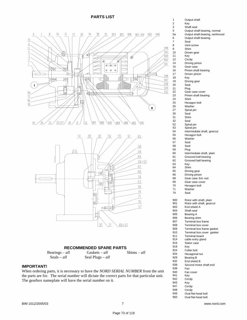
BIM 1012/2005/03 7 www.nord.com
PARTS LIST
RECOMMENDED SPARE PARTSBearings – all
Seals – all Gaskets – all
Seal Plugs – all Shims – all
IMPORTANT! When ordering parts, it is necessary to have the NORD SERIAL NUMBER from the unit the parts are for. The serial number will dictate the correct parts for that particular unit. The gearbox nameplate will have the serial number on it.
12355a678910111214151617181920212223242526273031325253545556575859606162636465666869707174
900901902904905906907908909910911914916918924925929932938939940941942943947948949950
Output shaftKeyShaft sealOutput shaft bearing, normalOutput shaft bearing, reinforcedOutput shaft bearingSealVent screwShimDriven gearKeyCirclipDriving pinionGear casePinion shaft bearingDriven pinionKeyDriving gearSealPlugGear case coverPinion shaft bearingShimHexagon boltWasherSpiral pinSealShimSealSpiral pinSpiral pinIntermediate shaft, gearcutHexagon boltWasherSealSealPlugIntermediate shaft, plainGrooved ball bearingGrooved ball bearingKeyShimDriving gearDriving pinionGear case 3rd.-red.Gear case coverHexagon boltWasherSeal
Rotor with shaft, plainRotor with shaft, gearcutEnd shield AShaft sealBearing ABearing shimTerminal box frameTerminal box coverTerminal box frame gasketTerminal box cover gasketTerminal boardcable entry glandStator caseKeyCollar boltHexagonal nutBearing BEnd shield BSecond motor shaft endFanFan coverKeyCirclipKeyCirclipCirclipOval flat-head boltOval flat-head bolt
II
I
Page 73 of 119

www.nord.com A42
INTRO
DU
CTION
G1000 – Subject to Change Without Notice
Lubrication
Lubrication TypesProper gearbox lubrication is essential in order to reduce friction, heat, and component wear. Lubricants reduce heat and wear by inserting a protective “fl uid boundary” between mating parts and preventing direct metal to metal con-tact. Lubricants also help prevent corrosion and oxidation, minimize foam, improve heat transfer, optimize reducer effi ciency, absorb shock loads and reduce noise.
Mounting position not only determines the proper fi ll-level but may also have some effect on fi nal reducer assembly. If considering any mounting positions that are not shown as catalog-standard options, it is critical that the customer consult with NORD prior to ordering. Unless otherwise specifi ed, NORD supplies most all gear units (*) factory-fi lled with the standard lubrication type and the appropriate amount of lubricating oil.
* Gear units SK10282, SK10382, SK11282, SK11382, SK12382, and SK9096.1 are supplied without oil.
Standard Oil Lubricants
Gear Unit Type Ambient Temperature Oil Type ISO Viscosity Manufacturer Brand / Type
Helical-Inline, Parallel-Shaft, & Helical-Bevel
-4 to 104 °F (-20 to 40 °C) MIN-EP VG 220 Shell / Omala 220 -40 to 140 °F (-40 to 60 °C) PAO VG 220 Mobil SHC 630 23 to 104 °F (-5 to 40 °C) FG VG 220 Shell / FM 220
Helical-Worm -22 to 122 °F (-30 to 50 °C) PAO VG 680 Mobil SHC 636
Optional Oil LubricantsGear Unit Type Ambient Temperature Oil Type ISO Viscosity Manufacturer Brand / Type
Helical-Inline, Parallel-Shaft, & Helical-Bevel
-31 to 176 °F (-35 to 80 °C) PAO VG 460 Mobil SHC 634-40 to 77 °F (-40 to 25 °C) PAO VG 150 Mobil SHC 629-40 to 140 °F (-40 to 60 °C) FG-PAO VG 220 Shell / Cassida GL 220
Helical-Worm -40 to 122 °F (-40 to 50 °C) FG-PAO VG 460 Shell / Cassida GL 460
Standard Bearing Grease LubricantsGrease Type / Thickener Ambient Temperature NLGI Grade Manufacturer Brand / Type
Standard (Li-Complex) -22 to 140 °F (-30 to 60 °C) NLGI 2 Shell Albida EP LC2 High Temp (Polyurea) -13 to 176 °F (-25 to 80 °C) NLGI 2 Mobil Polyrex EP 2 Food-Grade (Al-Complex) -13 to 104 °F (-25 to 40 °C) NLGI 2 Mobil Grease FM 222
Stocked Lubricant
Oil Formulation Codes
MIN-EP Mineral Oil with EP Additive
PAO Synthetic Polyalphaolefi n Oil
PG Synthetic Polyglycol Oil
FG Food-Grade Oil
FG-PAO Food-Grade, Synthetic Polyalphaolefi n Oil
Important Notes
• In worm gears avoid using (EP) gear oils that contain sulfur-phosphorous chemistries, as these additives can react adversely with bronze worm gears and accelerate wear.• Food grade lubricants must be in compliance with FDA 212 CFR 178.3570 and qualify as a NSF-H1 lubricant. Please consult with lubrication manufacture for more information. • When making a lubrication change, check with the lubrication supplier to assure compatibility and to obtain recommended cleaning or fl ushing procedures. • Do not mix different oils with different additive packages or different base oil formulation types. Polyglycol (PG) oils are not miscible with other oil types and should never be mixed with mineral oil, or Polyalphaolefi n (PAO) oil. • Please Consult NORD if considering cold-temperature oils below an ISO Viscosity VG100 or lower.
Page 74 of 119

www.nord.com A44
INTRO
DU
CTION
G1000 – Subject to Change Without Notice
In-line Foot Mount Positions & Oil Fill Quantities
M6
M1
M2
M4M5
M3
MountingPosition M1 M2 M3 M4 M5 M6
Quarts Liters Quarts Liters Quarts Liters Quarts Liters Quarts Liters Quarts LitersSK02 0.16 0.15 0.63 0.60 0.74 0.70 0.63 0.60 0.42 0.40 0.42 0.40SK03 0.32 0.30 1.06 1.00 0.85 0.80 0.95 0.90 0.63 0.60 0.63 0.60SK11E 0.26 0.25 0.53 0.50 0.58 0.55 0.42 0.40 0.37 0.35 0.37 0.35SK12 0.26 0.25 0.79 0.75 0.90 0.85 0.79 0.75 0.53 0.50 0.53 0.50SK13 0.63 0.60 1.32 1.25 1.16 1.10 1.27 1.20 0.74 0.70 0.74 0.70SK21E 0.63 0.60 1.27 1.20 1.27 1.20 1.06 1.00 1.06 1.00 1.06 1.00SK22 0.53 0.50 1.90 1.80 2.11 2.00 1.90 1.80 1.43 1.35 1.43 1.35SK23 1.37 1.30 2.54 2.40 2.43 2.30 2.48 2.35 1.69 1.60 1.69 1.60SK31E 1.16 1.10 2.85 2.70 2.33 2.20 2.43 2.30 1.80 1.70 1.80 1.70SK32 0.95 0.90 2.64 2.50 3.17 3.00 3.07 2.90 2.11 2.00 2.11 2.00SK33N 1.69 1.60 3.07 2.90 3.38 3.20 3.91 3.70 2.43 2.30 2.43 2.30SK41E 1.80 1.70 2.75 2.60 3.49 3.30 2.64 2.50 2.75 2.60 2.75 2.60SK42 1.37 1.30 4.76 4.50 4.76 4.50 4.55 4.30 3.38 3.20 3.38 3.20SK43 3.17 3.00 5.92 5.60 5.50 5.20 6.98 6.60 3.81 3.60 3.81 3.60SK51E 2.33 2.20 4.65 4.40 4.97 4.70 4.23 4.00 3.59 3.40 3.59 3.40SK52 2.64 2.50 7.40 7.00 7.19 6.80 7.19 6.80 5.39 5.10 5.39 5.10SK53 4.76 4.50 9.20 8.70 8.14 7.70 9.20 8.70 6.34 6.00 6.34 6.00SK62 6.87 6.50 15.9 15.0 13.7 13.0 16.9 16.0 15.9 15.0 15.9 15.0SK63 13.7 13.0 15.3 14.5 15.3 14.5 16.9 16.0 13.7 13.0 13.7 13.0SK72 10.6 10.0 24.3 23.0 19.0 18.0 27.5 26.0 24.3 23.0 24.3 23.0SK73 21.7 20.5 21.1 20.0 23.8 22.5 28.5 27.0 21.1 20.0 21.1 20.0SK82 14.8 14.0 37.0 35.0 28.5 27.0 46.5 44.0 33.8 32.0 33.8 32.0SK83 31.7 30.0 32.8 31.0 35.9 34.0 39.1 37.0 34.9 33.0 34.9 33.0SK92 26.4 25.0 77.1 73.0 49.7 47.0 80.3 76.0 55.0 52.0 55.0 52.0SK93 56.0 53.0 74.0 70.0 62.4 59.0 76.1 72.0 51.8 49.0 51.8 49.0SK102 38.1 36.0 83.5 79.0 69.8 66.0 107.8 102 75.1 71.0 75.1 71.0SK103 78.2 74.0 75.1 71.0 78.2 74.0 102.5 97.0 70.8 67.0 70.8 67.0
Page 75 of 119

www.nord.com H750
SERVICE
G1000 – Subject to Change Without Notice
M1B3/B5
M1B3/B5
M1B3/B5
M1B3/B5
M2V6/V3
M5B6/B5II
M4V5/V1
M3B8/B5I
M6B7/B5III
M2V6/V3
M5B6/B5II
M3B8/B5I
M4V5/V1
M6B7/B5III
M2V6/V3
M2V6/V3
M5B6/B5II M5
B6/B5II
M3B8/B5I
M3B8/B5I
M4V5/V1 M4
V5/V1
M6B7/B5III
M6B7/B5III
SK 11ESK 21ESK 31ESK 41ESK 51E
SK 02SK 12SK 22SK 32SK 42SK 52
SK 03SK 13SK 23SK 33NSK 43SK 53
SK 62SK 72SK 82SK 92SK 102SK 63*SK 73*SK 83*SK 93*SK 103*
*
*
= Vent = Oil Level = Oil Drain
Oil Plugs
Page 76 of 119

www.nord.com A77G1000 – Subject to Change Without Notice
INTR
OD
UCT
ION
Helical In-lineWeights - Reducer
Approximate Weights [lb]
Type W 56C 140TC 180TC 210TC 250TC 280TC 320TC 360TC
SK 02 26 44 44 – – – – – –SK 03 35 – – – – – – – –
SK 11 35 35 49 – – – – – –SK 12 48 48 57 – – – – – –SK 13 46 – – – – – – – –SK 12/02 49 49 – – – – – – –
SK 21 49 46 46 59 – – – – –SK 22 64 73 73 77 – – – – –SK 23 68 86 86 – – – – – –SK 22/02 77 93 93 – – – – – –
SK 31 59 62 62 66 – – – – –SK 32 88 90 90 95 – – – – –SK 33 N 95 103 103 – – – – –SK 32/12 106 115 115 132 – – – – –
SK 41 101 91 88 92 130 159 – – –SK 42 143 138 132 143 174 201 – – –SK 43 154 152 152 156 – – – – –SK 42/12 143 148 148 170 – – – – –
SK 51 121 105 105 117 147 150 199 – –SK 52 207 169 169 174 205 207 285 – –SK 53 227 185 185 189 – – – – –SK 52/12 207 179 179 234 – – – – –
SK 62 377 – – 317 354 392 392 567 567SK 63 328 295 288 299 330 332 405 – –SK 63/22 348 329 329 333 – – – – –SK 63/23 353 335 335 – – – – – –
SK 72 529 440 477 515 515 721 721SK 73 551 416 453 491 491 743 743SK 73/22 527 452 452 456 – – – – –SK 73/32 551 553 553 558 571 – – – –
SK 82 880 – – 666 702 741 741 962 962SK 83 787 – – 631 669 706 706 979 979SK 83/32 787 723 723 728 741 – – – –SK 83/42 842 837 837 848 879 906 – – –
SK 92 1268 – – – – 1215 1215 1350 1350SK 93 1182 – – 1184 1184 1239 1239 1374 1374SK 93/42 1237 1226 1226 1272 1272 1294 – – –SK 93/52 1301 – – 1276 1306 1308 1308 – –
SK 102 1821 – – – – – 1702 1837 1837SK 103 1775 – – 1667 1667 1722 1722 1857 1857SK 103/52 1784 1773 1773 1819 1819 1840 1860 – –
Above weights are approximate. Depending upon ratio, oil quantity and optional equipment, reducer weights may be different than shown.Exact weights can be obtained after the unit is fully asembled.
lb
Page 77 of 119

No.:
Date: 30-MAY-2012
TECHNICAL PROPOSAL
Three-phase induction motor - Squirrel cage rotor
Customer :
Product line : TEFC - W22 Super Premium Efficiency
Catalog Number : List Price : $
Notes:
Performed by: Checked:
Page 78 of 119

No.:
Date: 30-MAY-2012
DATA SHEETThree-phase induction motor - Squirrel cage rotor
Customer : Product line : TEFC - W22 Super Premium Efficiency
Frame : 184TOutput : 5 HPFrequency : 60 HzPoles : 2Full load speed : 3505Slip : 2.64 %Voltage : 208-230/460 VRated current : 13.2-12.0/5.99 ALocked rotor current : 98.2/49.1 ALocked rotor current (Il/In) : 8.2No-load current : 4.80/2.40 AFull load torque : 7.39 lb.ftLocked rotor torque : 240 %Breakdown torque : 350 %Design : AInsulation class : FTemperature rise : 80 KLocked rotor time : 30 s (hot)Service factor : 1.25Duty cycle : S1Ambient temperature : -20°C - +40°CAltitude : 1000Degree of Protection : IP55Approximate weight : 95 lbMoment of inertia : 0.22330 sq.ft.lbNoise level : 69 dB(A)
D.E. N.D.E. Load Power factor Efficiency (%)Bearings 6207 ZZ 6206 ZZ 100% 0.86 90.2Regreasing interval --- --- 75% 0.83 88.5Grease amount --- --- 50% 0.73 87.5
Notes:
Performed by Checked
Page 79 of 119

Percent of rated output (%)
A - E
ffici
ency
(%)
B - P
ower
fact
or
C - Slip
D - C
urrent at 230V (A)
0 10 20 30 40 50 60 70 80 90 100 110 120 130
40
50
60
70
80
90
100
0.4
0.5
0.6
0.7
0.8
0.9
1.0 0.0
1.0
2.0
3.0
4.0
5.0
0
4
8
12
16
A
B
C
D
No.:
Date: 30-MAY-2012
PERFORMANCE CURVES RELATED TO RATED OUTPUTThree-phase induction motor - Squirrel cage rotor
Customer : Product line : TEFC - W22 Super Premium Efficiency
Frame : 184TOutput : 5 HPFrequency : 60 HzFull load speed : 3505Voltage : 208-230/460 VRated current : 13.2-12.0/5.99 AInsulation class : F
Locked rotor current (Il/In) : 8.2Duty cycle : S1Service factor : 1.25Design : ALocked rotor torque : 240 %Breakdown torque : 350 %
Notes:
Performed by Checked
Page 80 of 119

0.0
0.5
1.0
1.5
2.0
2.5
3.0
3.5
4.0
4.5
5.0
A
0.0
1.0
2.0
3.0
4.0
5.0
6.0
7.0
8.0
9.0
10.0
B
0 10 20 30 40 50 60 70 80 90 100Speed related to rated speed (%)
A - T
orqu
e re
late
d to
rate
d to
rque
(C/C
n)
B - Current related to rated current (I/In)
No.:
Date: 30-MAY-2012
CHARACTERISTIC CURVES RELATED TO SPEEDThree-phase induction motor - Squirrel cage rotor
Customer : Product line : TEFC - W22 Super Premium Efficiency
Frame : 184TOutput : 5 HPFrequency : 60 HzFull load speed : 3505Voltage : 208-230/460 VRated current : 13.2-12.0/5.99 AInsulation class : F
Locked rotor current (Il/In) : 8.2Duty cycle : S1Service factor : 1.25Design : ALocked rotor torque : 240 %Breakdown torque : 350 %
Notes:
Performed by Checked
Page 81 of 119
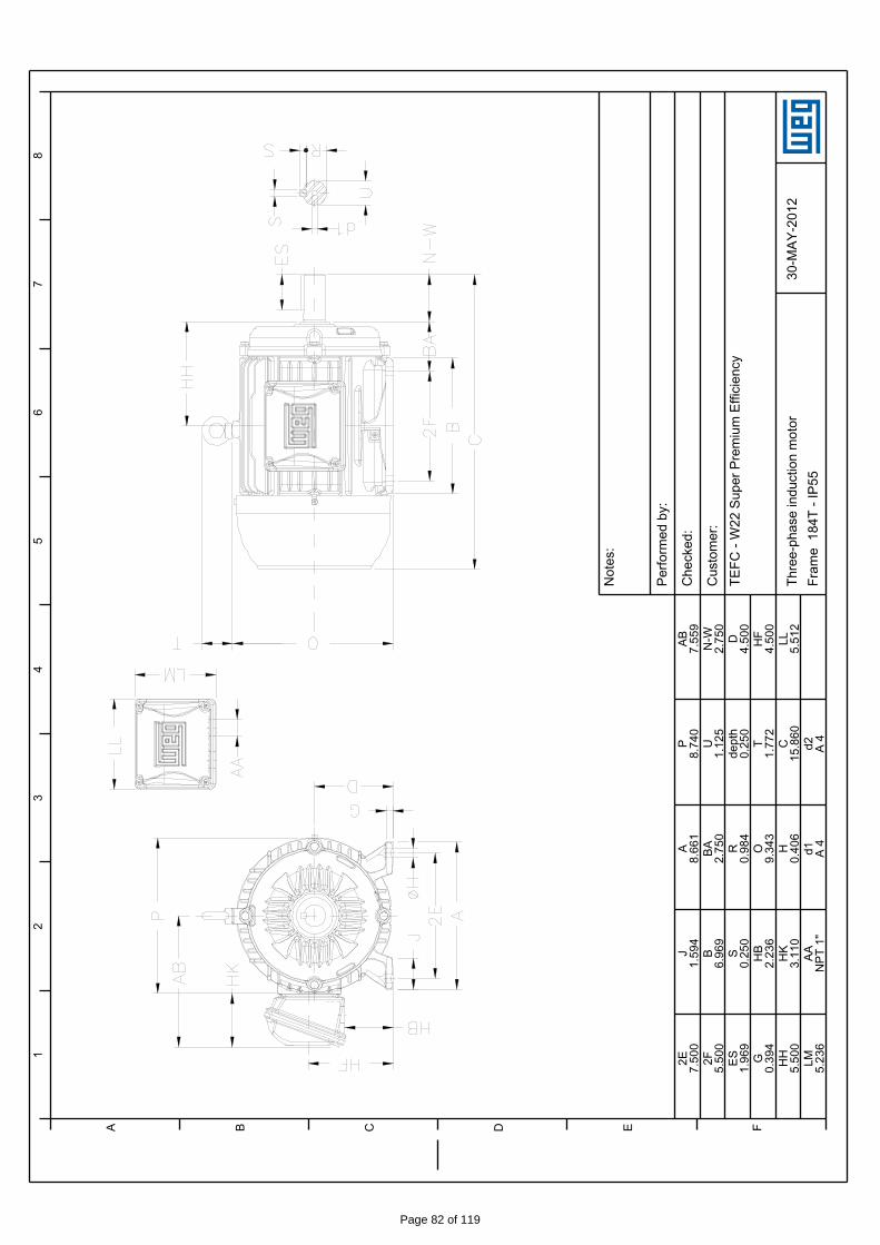
12
34
56
78
A B C D E F
30-M
AY-2
012
Thre
e-ph
ase
indu
ctio
n m
otor
Fram
e 1
84T
- IP5
5
Not
es:
Perfo
rmed
by:
Che
cked
:
Cus
tom
er:
TEFC
- W
22 S
uper
Pre
miu
m E
ffici
ency
2E 7.50
0J
1.59
4A
8.66
1P
8.74
0AB 7.55
92F 5.50
0B
6.96
9BA 2.75
0U
1.12
5N
-W2.
750
ES 1.96
9S
0.25
0R
0.98
4de
pth
0.25
0D
4.50
0G
0.39
4H
B2.
236
O9.
343
T1.
772
HF
4.50
0H
H5.
500
HK
3.11
0H
0.40
6C
15.8
60LL 5.51
2LM 5.23
6AA
NPT
1"
d1 A 4
d2 A 4
Page 82 of 119
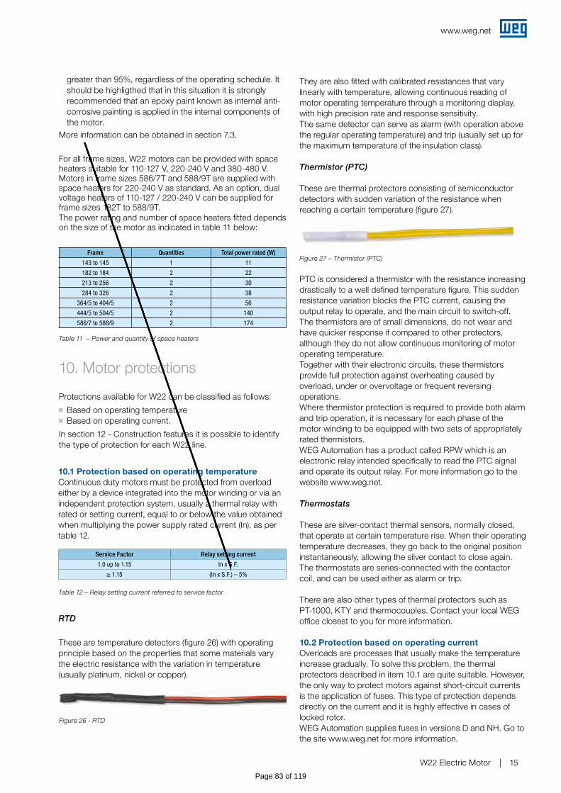
www.weg.net
W22 Electric Motor 15
10. Motor protections
Protections available for W22 can be classified as follows:g Based on operating temperatureg Based on operating current.
In section 12 - Construction features it is possible to identify the type of protection for each W22 line.
Table 11 – Power and quantity of space heaters
Frame Quantities Total power rated (W)
143 to 145 1 11
182 to 184 2 22
213 to 256 2 30
284 to 326 2 38
364/5 to 404/5 2 56
444/5 to 504/5 2 140
586/7 to 588/9 2 174
10.1 Protection based on operating temperatureContinuous duty motors must be protected from overload either by a device integrated into the motor winding or via an independent protection system, usually a thermal relay with rated or setting current, equal to or below the value obtained when multiplying the power supply rated current (In), as per table 12.
Service Factor Relay setting current
1.0 up to 1.15 In x S.F.
≥ 1.15 (In x S.F.) – 5%
Table 12 – Relay setting current referred to service factor
Figure 26 - RTD
RTD
They are also fitted with calibrated resistances that vary linearly with temperature, allowing continuous reading of motor operating temperature through a monitoring display, with high precision rate and response sensitivity. The same detector can serve as alarm (with operation above the regular operating temperature) and trip (usually set up for the maximum temperature of the insulation class).
Thermistor (PTC)
These are thermal protectors consisting of semiconductordetectors with sudden variation of the resistance whenreaching a certain temperature (figure 27).
PTC is considered a thermistor with the resistance increasing drastically to a well defined temperature figure. This sudden resistance variation blocks the PTC current, causing the output relay to operate, and the main circuit to switch-off.The thermistors are of small dimensions, do not wear and have quicker response if compared to other protectors, although they do not allow continuous monitoring of motor operating temperature.Together with their electronic circuits, these thermistors provide full protection against overheating caused by overload, under or overvoltage or frequent reversing operations.Where thermistor protection is required to provide both alarm and trip operation, it is necessary for each phase of the motor winding to be equipped with two sets of appropriately rated thermistors.WEG Automation has a product called RPW which is an electronic relay intended specifically to read the PTC signal and operate its output relay. For more information go to the website www.weg.net.
Thermostats
These are silver-contact thermal sensors, normally closed, that operate at certain temperature rise. When their operating temperature decreases, they go back to the original position instantaneously, allowing the silver contact to close again.The thermostats are series-connected with the contactor coil, and can be used either as alarm or trip.
There are also other types of thermal protectors such as PT-1000, KTY and thermocouples. Contact your local WEG office closest to you for more information.
10.2 Protection based on operating currentOverloads are processes that usually make the temperature increase gradually. To solve this problem, the thermal protectors described in item 10.1 are quite suitable. However, the only way to protect motors against short-circuit currents is the application of fuses. This type of protection depends directly on the current and it is highly effective in cases of locked rotor.WEG Automation supplies fuses in versions D and NH. Go to the site www.weg.net for more information.
These are temperature detectors (figure 26) with operating principle based on the properties that some materials vary the electric resistance with the variation in temperature (usually platinum, nickel or copper).
Figure 27 – Thermistor (PTC)
greater than 95%, regardless of the operating schedule. It should be highligthed that in this situation it is strongly recommended that an epoxy paint known as internal anti-corrosive painting is applied in the internal components of the motor.
More information can be obtained in section 7.3.
For all frame sizes, W22 motors can be provided with space heaters suitable for 110-127 V, 220-240 V and 380-480 V. Motors in frame sizes 586/7T and 588/9T are supplied with space heaters for 220-240 V as standard. As an option, dual voltage heaters of 110-127 / 220-240 V can be supplied for frame sizes 182T to 588/9T.The power rating and number of space heaters fitted depends on the size of the motor as indicated in table 11 below:
Page 83 of 119

Page 84 of 119

WED-002
INSTALATION OF SPACE HEATERS IN INDUCTION MOTORS
Page 1 of 2 Source: WEG / TOP - 0137
NORM Rev. 00 06/01/2004
Company: WEM Origin:
Edited by: Valone Gomes
1. OBJECTIVE: This standard aims at providing specification and installation procedures for “space-heater” installed in WEG motors.
2. WATTAGE AND CONNECTIONS:
SPACE HEATER VOLTAGE FRAMES
110 ± 22V 220 ± 44V 440 ± 88V NEMA IEC
TOTAL WATTS
(W ± 10%) 3) TYPE CONNECTION/Req. TYPE CONNECTION/Req. TYPE CONNECTION/Req.
63 71 80
143 145 90
81) 20W/m-110V
Req. = 1,512 Ώ
20W/m-220V
Req. = 6,050Ώ
20W/m-440V
Req.=12,100Ώ 100
182 184 112
162) 20W/m-110V
Req. = 756Ώ
20W/m-220V
Req. = 3,025Ώ
20W/m-440V
Req. = 6,050Ώ
213 215 132 24 30W/m-
110V
Req.= 504Ώ
30W/m-220V
Req. = 2,017Ώ
30W/m-440V
Req. = 8,067Ώ 254 256 160
284 286 180
324 326 200
48 30W/m-
110V
Req. = 252Ώ
30W/m-220V
Req. = 1,008.5Ώ
30W/m-440V
Req = 40,033.5 Ώ
364 365 225
404 405 250
79 35W/m-110V
Req.= 153Ώ
35W/m-220V
Req. = 612Ώ
35W/m-
440V
Req.=2,450Ώ 444 445 280
447 449
504/5 315
5008 315B
586/7 355
158
35W/m-110V
Req. = 76.5Ώ
35W/m-220V
Req. = 306Ώ
35W/m-440V
Req. = 1,225Ώ
Page 85 of 119
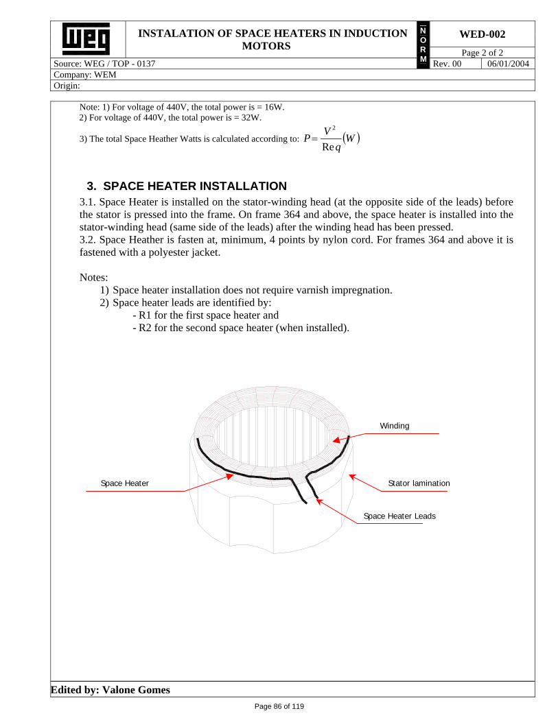
WED-002
INSTALATION OF SPACE HEATERS IN INDUCTION MOTORS
Page 2 of 2 Source: WEG / TOP - 0137
NORM Rev. 00 06/01/2004
Company: WEM Origin:
Edited by: Valone Gomes
Note: 1) For voltage of 440V, the total power is = 16W. 2) For voltage of 440V, the total power is = 32W.
3) The total Space Heather Watts is calculated according to: Wq
VP
Re
2
3. SPACE HEATER INSTALLATION 3.1. Space Heater is installed on the stator-winding head (at the opposite side of the leads) before the stator is pressed into the frame. On frame 364 and above, the space heater is installed into the stator-winding head (same side of the leads) after the winding head has been pressed. 3.2. Space Heather is fasten at, minimum, 4 points by nylon cord. For frames 364 and above it is fastened with a polyester jacket. Notes:
1) Space heater installation does not require varnish impregnation. 2) Space heater leads are identified by:
- R1 for the first space heater and - R2 for the second space heater (when installed).
Space Heater Leads
Stator lamination
Winding
Space Heater
Page 86 of 119

Tab 4 Pump Accessories
Page 87 of 119

Page 88 of 119
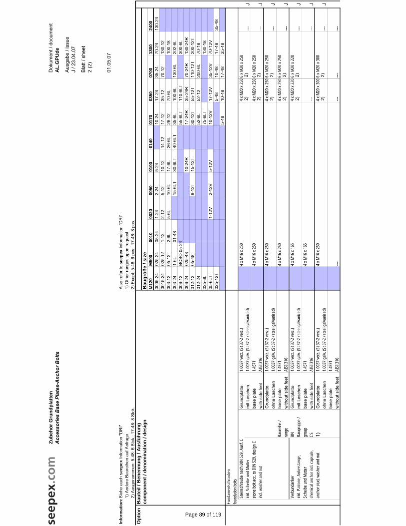
Info
rmat
ion
:Sie
he a
uch
seep
ex In
form
atio
n "D
RI"
Als
o re
fer t
o se
epex
info
rmat
ion
"DR
I"1)
And
ere
Bau
reih
en a
uf A
nfra
ge1)
Oth
er ra
nges
upo
n re
ques
t2)
Aus
geno
mm
en: 5
-48:
6 S
tck.
; 17-
48: 8
Stc
k.2)
Exe
pt: 5
-48:
6 p
cs.;
17-4
8: 8
pcs
.O
pti
on
Bau
teil
/ Ben
enn
un
g /
Au
sfü
hru
ng
com
po
nen
t / d
eno
min
atio
n /
des
ign
Bau
grö
ße
/ siz
eM
120
M50
000
1000
2000
5001
0001
4001
7003
5007
0013
0024
0000
05-2
402
5-24
05-2
41-
242-
245-
2410
-24
17-2
435
-24
70-2
413
0-24
0015
-24
025-
121-
122-
125-
1210
-12
14-1
217
-12
35-1
270
-12
130-
1200
3-12
05-1
22-
6L5-
6L10
-6L
17-6
L26
-6L
26-1
270
-6L
100-
1800
3-24
1-6L
01-4
815
-6LT
30-6
LT40
-6LT
35-6
L10
0-6L
130-
6L20
2-6L
006-
12B
CS
O 0
5-24
55-6
LT11
0-6L
T30
0-6L
006-
2402
5-48
10-2
4R17
-24R
35-2
4R70
-24R
130-
24R
012-
1205
-48
8-12
T15
-12T
30-1
2T55
-12T
110-
12T
200-
12T
012-
2452
-6L
52-1
220
0-6L
70-1
802
5-6L
75-6
LT13
0-18
05-6
LT1-
12V
2-12
V5-
12V
10-1
2V17
-12V
35-1
2V70
-12V
025-
12T
5-48
10-4
817
-48
35-4
85-
4810
-48
17-4
835
-48
Fund
amen
tschr
aube
nfou
ndati
on bo
ltsSt
einsc
hrau
be na
ch D
IN 52
9, Au
sf. C
Gru
ndpl
atte
1.003
7 ver
z. (S
t 37-
2 ver
z.)4 x
M16
x 25
04 x
M20
x 25
06 x
M20 x
250
inkl. S
cheib
e und
Mutt
erm
it La
sche
n1.0
037 g
alv. (
St 37
-2 / s
teel g
alvan
ized)
---
Jsto
ne bo
lt acc
. to D
IN 52
9, de
sign C
base
pla
te1.4
571
4 x M
16 x
250
4 x M
20 x
2506
x M2
0 x 25
0inc
l. was
her a
nd nu
tw
ith s
ide
feet
AISI
316
---
JG
rund
plat
te1.0
037 v
erz.
(St 3
7-2 v
erz.)
4 x M
16 x
250
4 x M
20 x
2506
x M2
0 x 25
0oh
ne L
asch
en1.0
037 g
alv. (
St 37
-2 / s
teel g
alvan
ized)
---
JBa
ureih
e /ba
se p
late
1.457
14 x
M16
x 25
04 x
M20
x 25
06 x
M20 x
250
rang
ew
ithou
t sid
e fe
etAI
SI 31
6--
-J
Verb
unda
nker
BN
Gru
ndpl
atte
1.003
7 ver
z. (S
t 37-
2 ver
z.)4 x
M16
x 16
54 x
M20
x 22
06 x
M20 x
220
inkl. P
atron
e, An
kerst
ange
,Ba
ugru
ppe /
mit
Lasc
hen
1.003
7 galv
. (St
37-2
/ stee
l galv
anize
d)--
-J
Sche
ibe un
d Mutt
ergr
oup
base
pla
te1.4
571
4 x M
16 x
165
chem
ical a
ncho
r incl.
caps
ule,
CSw
ith s
ide
feet
AISI
316
---
---
Jan
chor
stud
, was
her a
nd nu
t1)
Gru
ndpl
atte
1.003
7 ver
z. (S
t 37-
2 ver
z.)4 x
M16
x 25
04 x
M20
x 30
06 x
M20 x
300
ohne
Las
chen
1.003
7 galv
. (St
37-2
/ stee
l galv
anize
d)--
-J
base
pla
te1.4
571
with
out s
ide
feet
AISI
316
---
---
---
---
2)2) 2)
2) 2)2) 2)
2) 2)2)
2)2)
Zu
beh
ör
Gru
nd
pla
tten
Acc
esso
ries
Bas
e Pl
ates
-Anc
hor B
olts
Dok
umen
t / d
ocum
ent
AL
.GP
Ud
e
Aus
gabe
/ is
sue
J / 2
3.04
.07
Bla
tt / s
heet
2
(2)
01.0
5.07
Page 89 of 119

seepex Inc. 511 Speedway Drive Enon, OH 45323 Phone (937) 864-7150 Fax (937) 864-7157 [email protected] www.seepex.com
Pressure Switch/Gauge Details Project: Weaver Constr-Englewood, CO-Ambiente H2O-Harold D. Thompson Water Reclamation Facility-PO#: 9103
Digested Sludge BN 52-6L 832027-028 DSP-1 & 2 Mounting: (Check One) Isolation Ring: X Diaphragm Seal: None Manufacturer: Onyx PSW 5“ Pressure Gauge Detail:
1. Manufacturer: Ashcroft 2. Model No.: 1008
3. Liquid Fill? No
4. Face Diameter: 4“
5. Range: 0 - 100 PSI
Pressure Switch Detail:
1. Manufacturer: Ashcroft 2. Model No.: B4 24 B
3. Enclosure: NEMA 4X
4. Pressure Range: 0 – 100 PSI
5. Manual Reset? No
6. SPDT or DPDT? SPDT
Page 90 of 119
seepex Inc. 511 Speedway Drive Enon, OH 45323 Phone (937) 864-7150 Fax (937) 864-7157 [email protected] www.seepex.com
Pressure Switch/Gauge Details Project: Weaver Constr-Englewood, CO-Ambiente H2O-Harold D. Thompson Water Reclamation Facility-PO#: 9103
Scum BN 35-6L 832029-030 SCP-1 & 2 Mounting: (Check One) Isolation Ring: X Diaphragm Seal: None Manufacturer: Onyx PSW 4“ Pressure Gauge Detail:
1. Manufacturer: Ashcroft 2. Model No.: 1008
3. Liquid Fill? No
4. Face Diameter: 4“
5. Range: 0 - 100 PSI
Pressure Switch Detail:
1. Manufacturer: Ashcroft 2. Model No.: B4 24 B
3. Enclosure: NEMA 4X
4. Pressure Range: 0 – 100 PSI
5. Manual Reset? No
6. SPDT or DPDT? SPDT
Page 91 of 119

Smart BoxThe Preengineered Pump Protection Package
Features• Over Pressure Protection
• Run Dry Protection
• Functions as a Local Control Station
• Simple Two-Button Operation
• Panel Lights Show Pump Status
• Microprocessor Based
• Preprogrammed Ready to Run
• Corrosion Resistant Fiberglass NEMA-4X
Enclosure for Indoor or Outdoor Service
• Easy Interface with Fixed Speed or Variable Speed Pumps
• Easy Interface to Remote Controls
• Broken Wire Detection
• Safe 24 Volt Signal Wiring
ApplicationsThe Onyx Smart Box protects pumps from damage anddowntime caused by run dry or over pressure conditions. It can be combined with our Isolator Ring for dependableoperation with viscous, abrasive, corrosive, or volatile fluids or suspensions and slurries.
835 Industrial Hwy • Cinnaminson, NJ 08077Phone: 856/829-2888 • Fax: 856/829-3080 • www.onyxvalve.com
Onyx Isolator Ring and Smart Box protectsperistaltic hose pumps from over pressure whichcould rupture the hose. They can also monitorlevel of the lubricant in the hose chamber toprevent damage from operating without oil.
FunctionThe Smart Box is a preprogrammed, microprocessorbased controller. It monitors a 2-point pressure switchto ensure that pumps operate within design limits.
If pump discharge pressure exceeds safe limits, theSmart Box stops the pump, sounds the (optional)alarm, and the HIGH TRIP indicator lamp comes on.Pressing the STOP button silences the alarm andpermits a restart. The Smart Box blocks any attempt torestart the pump until excess pressure is relieved.
If the pump runs dry, discharge pressure falls below thelow threshold. In this case the Smart Box stops thepump, sounds the (optional) alarm, and the RUN DRYindicator lamp comes on. Pressing the STOP button silences the alarm and permits a restart. Each time the pump starts, the Smart Box allows a 90 second grace period for the pump to prime itself.
OperationThe STOP/RESET button is a 2-position maintained button.
Push the STOP/RESET button to stop the pump. If thereare remote controls connected to the Smart Box, pressingSTOP/RESET locks out all “run” commands from allsources. In this condition the READY light will be out.
Twist the STOP/RESET button to unlock it. It pops into the“out” position, and the READY light turns on. This automat-ically puts the Smart Box into “remote” mode, allowing theSmart Box to respond to remote “run” commands.
In normal mode, the operator starts the pump by twisting the STOP button and pressing the green START button.The READY light goes out and the green RUN button lights.
ONYX VALVE
Pressure Isolator
RingNew Patented Design Assures Accuracy
and Maintenance-Free OperationPatent #5,708,201
ON
YX
VA
LVE
Kynar® is a registered trademark of Atofina ChemicalsTeflon®, Nordel®, Viton®, and Hypalon® are registered trademarks of DuPont©Copyright, Onyx Valve, 2003 Printed in USA
Your local representative is:
Pinch ValvesManual/Pneumatic/Electric
Pump Connectors and Expansion Joints
Onyx Smart Box ensures that progressing cavity pumpsoperate within design parameters.
Options:• Audible Alarm
• Explosion Proof Enclosure
• Seal Flush Kit
• Fused Disconnect
• Circuit Breaker
• Key Lock on STOP Button
• Motor Starter
• VFD
• Level Control Package
Page 92 of 119
The Onyx Isolator RingOutperforms Conventional Isolator Rings and Standard Diaphragm SealsObtaining accurate pressure readings on pipelines isdifficult because slurries, abrasives, and solids cloggauges, switches, and transmitters. Standarddiaphragm seals–drilled or welded at a point on thepipeline–provide a temporary solution, but arevulnerable to plugging and stop working when slurrysolidifies in the seal chamber. Conventional isolatorrings consist of a rubber “inner tube” captured in asteel ring. The assembly is installed between flanges in the process pipe. Clear instrument fluid behind therubber membrane transmits pressure to the gauge. The inside diameter of the ring assembly matches the adjacent pipe so the ring is continually cleaned by the motion of the process fluid. A common problem with this type of isolator ring is that any air inside the instrument will compress when pressurized.
The Onyx Isolator Ring:The Solid Solution for Solving YourPressure Measurement Problems
The Onyx Isolator Ring provides a practical, cost-effective method for obtaining accurate pressuremeasurements on slurries, abrasives, and hard-to-handle materials. The Onyx Isolator Ring’s new patenteddesign solves the problems associated with isolator
rings on the market today. TheOnyx Isolator Ring is vacuum-filled at the factory with high-viscosity silicone fluid; thenpermanently sealed with Onyx’sRevolutionary “Module-Seal”.With the Onyx Isolator Ring,there is no fill port anywhere onthe assembly: gauges, switches,and transmitters are supplied
separately, are prefilled with Onyx’sspecial fitting attached. You have theoption of selecting any combination ofisolator ring and gauge and simply
snapping them together. With theOnyx Isolator Ring, you are
guaranteed hassle-freeoperation and added protectionfor your sensitive indicationinstrumentation.
Practical Applications of The Onyx Isolator RingThe Onyx Isolator Ring can be used in a variety ofindustries such as chemical, food & beverage, mining,pulp & paper, and wastewater treatment. Typical applications include:O Pressure measurement of slurries, corrosives, and
difficult fluidsO Tank level indicationO Monitoring pressure on long distance pipelines to
detect line breakageO Monitoring pressure drop across a filter or pump using
two sensors with a differential pressure switchO Measuring the output pressure of a pumpO Sending a signal to stop a pump or open a
by-pass valve
Proven Benefits of The Onyx Isolator RingO Gauges can be removed or replaced without
interrupting processO Gauges can be replaced without vacuum filling O No tools required to change pressure instrument
(simply remove and replace by turning the lock ring)O No snubber required (needle functions as
built-in snubber)O Improved safety (process liquid cannot escape if gauge
is removed, even if process pipe is under pressure)O High accuracy (because air can never get into
the system)O No isolation valve requiredO Gauges can be rotated by hand to face any directionO Isolation rings and gauges can be stocked separately
(combine as needed on the spot)
Technical Specifications of The Onyx Isolator RingCenter Section: • Carbon Steel*
• 316 Stainless Steel• Carpenter-20
End Plates: • Acetal • Kynar®
• 316 Stainless Steel • Titanium • Teflon® • Carpenter-20
Elastomer: • Neoprene -20°F 220°F• Nitrile (Buna-N) -20°F 180°F• EPDM (Nordel®) -20°F 300°F• Fluoroelastomer (Viton®)
(Available with optional Teflon coatings) -20°F 375°F• Chlorosulfonated Polyethylene (Hypalon®) -20°F 250°F
Fill Fluid: • Silicone Fluid -40°F 400°F• Food Grade Silicone (Optional) -20°F 400°F
Pressure Range: Vacuum to +1,000 psi The Onyx Isolator has been tested by an independent lab to 1,500 psi
SIZE ØA B1 2.50 1.87
1-1/2 3.25 1.872 4.00 1.87
2-1/2 4.75 1.873 5.25 1.874 6.75 2.125 7.62 2.256 8.62 2.258 10.87 2.2510 13.25 2.8112 16.00 3.1214 17.62 3.1216 20.12 3.1218 21.50 3.1220 23.75 3.1224 32.00 3.12
Center Material: Carbon Steel 316 Stainless Steel Carpenter-20 Stainless SteelEnd Plate Material: Acetal 316 Stainless Steel Carpenter-20 Stainless Steel TeflonSleeve Elastomer:
Module Seal Stinger Fitting Material: Brass (Std) 316 Stainless SteelPipe Fittings Material (1/2 NPT Std): Carbon Steel 316 S.S.Fill Fluid: Silicone (Std) (-40°F TO 400°F) Vegetable Oil (FDA)Other Pressure Rating: 1,000 PSIAll dimensions are in inches.Series PSW
1/4˝ fittingsbreak easily
Brand X ONYX
ONYX brazed 7/8˝ diametermounting post can easilysupport multipleinstruments
Slurry clogsdiaphragm sealWafer Ring
Isolator is notaffected byslurry
Pressure Gauge
Elastomer Seal
End Plates
Rubber Sleeve
BourdonTube
Stinger FittingLock Ring
Hollow NeedleMetal Center
Fill Fluid
This stretches the rubber membrane,causing accuracy to degrade or theinstrument to malfunction. (An air bubble as small as a pea can make an isolatornonfunctional). To counter this obstacle,
isolator ring manufacturers use a vacuumpump to evacuate the air from the isolator
before injecting the instrument fluid. To removethe gauge for replacement or calibration, the entire
ring and gauge assembly must be removed from theprocess pipe and the gauge and ring have to bedrained, evacuated, and refilled. The customer for thistype of isolator ring will experience much downtime andexpense. Some manufacturers try to circumvent thisproblem by adding a valve to the ring assembly. Thisholds the fluid in the ring, but attempting to fill thegauge by turning it upside down and pouring fluid intoit traps an air pocket at the tip of the Bourdon tube.Also, attempting to remount the gauge by covering theconnection with your finger while turning it upright andscrewing it into the isolator is rarely successful.
Diaphragm sealprovides temporarysolution, but stopsworking when slurrysolidifies in the seal chamber.
The gauge can beremoved from the ringwithout breaking thevacuum seal. Therubber “Module Seal”closes the instant theprobe is removed.
Robust 0.87˝ diameter mounting post resists breakage. Provides sturdy mounting for heavy gauges and instruments. Up to three gauges, pressure switches, and transmitters can be combined on one isolator without additional support.
*Coatings available. Consult factory.Sizes, dimensions, and materials may vary depending on series.
PSWPSR
PSQ
PSS
Page 93 of 119

Smart BoxThe Preengineered Pump Protection Package
Features• Over Pressure Protection
• Run Dry Protection
• Functions as a Local Control Station
• Simple Two-Button Operation
• Panel Lights Show Pump Status
• Microprocessor Based
• Preprogrammed Ready to Run
• Corrosion Resistant Fiberglass NEMA-4X
Enclosure for Indoor or Outdoor Service
• Easy Interface with Fixed Speed or Variable Speed Pumps
• Easy Interface to Remote Controls
• Broken Wire Detection
• Safe 24 Volt Signal Wiring
ApplicationsThe Onyx Smart Box protects pumps from damage anddowntime caused by run dry or over pressure conditions. It can be combined with our Isolator Ring for dependableoperation with viscous, abrasive, corrosive, or volatile fluids or suspensions and slurries.
835 Industrial Hwy • Cinnaminson, NJ 08077Phone: 856/829-2888 • Fax: 856/829-3080 • www.onyxvalve.com
Onyx Isolator Ring and Smart Box protectsperistaltic hose pumps from over pressure whichcould rupture the hose. They can also monitorlevel of the lubricant in the hose chamber toprevent damage from operating without oil.
FunctionThe Smart Box is a preprogrammed, microprocessorbased controller. It monitors a 2-point pressure switchto ensure that pumps operate within design limits.
If pump discharge pressure exceeds safe limits, theSmart Box stops the pump, sounds the (optional)alarm, and the HIGH TRIP indicator lamp comes on.Pressing the STOP button silences the alarm andpermits a restart. The Smart Box blocks any attempt torestart the pump until excess pressure is relieved.
If the pump runs dry, discharge pressure falls below thelow threshold. In this case the Smart Box stops thepump, sounds the (optional) alarm, and the RUN DRYindicator lamp comes on. Pressing the STOP button silences the alarm and permits a restart. Each time the pump starts, the Smart Box allows a 90 second grace period for the pump to prime itself.
OperationThe STOP/RESET button is a 2-position maintained button.
Push the STOP/RESET button to stop the pump. If thereare remote controls connected to the Smart Box, pressingSTOP/RESET locks out all “run” commands from allsources. In this condition the READY light will be out.
Twist the STOP/RESET button to unlock it. It pops into the“out” position, and the READY light turns on. This automat-ically puts the Smart Box into “remote” mode, allowing theSmart Box to respond to remote “run” commands.
In normal mode, the operator starts the pump by twisting the STOP button and pressing the green START button.The READY light goes out and the green RUN button lights.
ONYX VALVE
Pressure Isolator
RingNew Patented Design Assures Accuracy
and Maintenance-Free OperationPatent #5,708,201
ON
YX
VA
LVE
Kynar® is a registered trademark of Atofina ChemicalsTeflon®, Nordel®, Viton®, and Hypalon® are registered trademarks of DuPont©Copyright, Onyx Valve, 2003 Printed in USA
Your local representative is:
Pinch ValvesManual/Pneumatic/Electric
Pump Connectors and Expansion Joints
Onyx Smart Box ensures that progressing cavity pumpsoperate within design parameters.
Options:• Audible Alarm
• Explosion Proof Enclosure
• Seal Flush Kit
• Fused Disconnect
• Circuit Breaker
• Key Lock on STOP Button
• Motor Starter
• VFD
• Level Control Package
Page 94 of 119

The Onyx Isolator RingOutperforms Conventional Isolator Rings and Standard Diaphragm SealsObtaining accurate pressure readings on pipelines isdifficult because slurries, abrasives, and solids cloggauges, switches, and transmitters. Standarddiaphragm seals–drilled or welded at a point on thepipeline–provide a temporary solution, but arevulnerable to plugging and stop working when slurrysolidifies in the seal chamber. Conventional isolatorrings consist of a rubber “inner tube” captured in asteel ring. The assembly is installed between flanges in the process pipe. Clear instrument fluid behind therubber membrane transmits pressure to the gauge. The inside diameter of the ring assembly matches the adjacent pipe so the ring is continually cleaned by the motion of the process fluid. A common problem with this type of isolator ring is that any air inside the instrument will compress when pressurized.
The Onyx Isolator Ring:The Solid Solution for Solving YourPressure Measurement Problems
The Onyx Isolator Ring provides a practical, cost-effective method for obtaining accurate pressuremeasurements on slurries, abrasives, and hard-to-handle materials. The Onyx Isolator Ring’s new patenteddesign solves the problems associated with isolator
rings on the market today. TheOnyx Isolator Ring is vacuum-filled at the factory with high-viscosity silicone fluid; thenpermanently sealed with Onyx’sRevolutionary “Module-Seal”.With the Onyx Isolator Ring,there is no fill port anywhere onthe assembly: gauges, switches,and transmitters are supplied
separately, are prefilled with Onyx’sspecial fitting attached. You have theoption of selecting any combination ofisolator ring and gauge and simply
snapping them together. With theOnyx Isolator Ring, you are
guaranteed hassle-freeoperation and added protectionfor your sensitive indicationinstrumentation.
Practical Applications of The Onyx Isolator RingThe Onyx Isolator Ring can be used in a variety ofindustries such as chemical, food & beverage, mining,pulp & paper, and wastewater treatment. Typical applications include:O Pressure measurement of slurries, corrosives, and
difficult fluidsO Tank level indicationO Monitoring pressure on long distance pipelines to
detect line breakageO Monitoring pressure drop across a filter or pump using
two sensors with a differential pressure switchO Measuring the output pressure of a pumpO Sending a signal to stop a pump or open a
by-pass valve
Proven Benefits of The Onyx Isolator RingO Gauges can be removed or replaced without
interrupting processO Gauges can be replaced without vacuum filling O No tools required to change pressure instrument
(simply remove and replace by turning the lock ring)O No snubber required (needle functions as
built-in snubber)O Improved safety (process liquid cannot escape if gauge
is removed, even if process pipe is under pressure)O High accuracy (because air can never get into
the system)O No isolation valve requiredO Gauges can be rotated by hand to face any directionO Isolation rings and gauges can be stocked separately
(combine as needed on the spot)
Technical Specifications of The Onyx Isolator RingCenter Section: • Carbon Steel*
• 316 Stainless Steel• Carpenter-20
End Plates: • Acetal • Kynar®
• 316 Stainless Steel • Titanium • Teflon® • Carpenter-20
Elastomer: • Neoprene -20°F 220°F• Nitrile (Buna-N) -20°F 180°F• EPDM (Nordel®) -20°F 300°F• Fluoroelastomer (Viton®)
(Available with optional Teflon coatings) -20°F 375°F• Chlorosulfonated Polyethylene (Hypalon®) -20°F 250°F
Fill Fluid: • Silicone Fluid -40°F 400°F• Food Grade Silicone (Optional) -20°F 400°F
Pressure Range: Vacuum to +1,000 psi The Onyx Isolator has been tested by an independent lab to 1,500 psi
SIZE ØA B1 2.50 1.87
1-1/2 3.25 1.872 4.00 1.87
2-1/2 4.75 1.873 5.25 1.874 6.75 2.125 7.62 2.256 8.62 2.258 10.87 2.2510 13.25 2.8112 16.00 3.1214 17.62 3.1216 20.12 3.1218 21.50 3.1220 23.75 3.1224 32.00 3.12
Center Material: Carbon Steel 316 Stainless Steel Carpenter-20 Stainless SteelEnd Plate Material: Acetal 316 Stainless Steel Carpenter-20 Stainless Steel TeflonSleeve Elastomer:
Module Seal Stinger Fitting Material: Brass (Std) 316 Stainless SteelPipe Fittings Material (1/2 NPT Std): Carbon Steel 316 S.S.Fill Fluid: Silicone (Std) (-40°F TO 400°F) Vegetable Oil (FDA)Other Pressure Rating: 1,000 PSIAll dimensions are in inches.Series PSW
1/4˝ fittingsbreak easily
Brand X ONYX
ONYX brazed 7/8˝ diametermounting post can easilysupport multipleinstruments
Slurry clogsdiaphragm sealWafer Ring
Isolator is notaffected byslurry
Pressure Gauge
Elastomer Seal
End Plates
Rubber Sleeve
BourdonTube
Stinger FittingLock Ring
Hollow NeedleMetal Center
Fill Fluid
This stretches the rubber membrane,causing accuracy to degrade or theinstrument to malfunction. (An air bubble as small as a pea can make an isolatornonfunctional). To counter this obstacle,
isolator ring manufacturers use a vacuumpump to evacuate the air from the isolator
before injecting the instrument fluid. To removethe gauge for replacement or calibration, the entire
ring and gauge assembly must be removed from theprocess pipe and the gauge and ring have to bedrained, evacuated, and refilled. The customer for thistype of isolator ring will experience much downtime andexpense. Some manufacturers try to circumvent thisproblem by adding a valve to the ring assembly. Thisholds the fluid in the ring, but attempting to fill thegauge by turning it upside down and pouring fluid intoit traps an air pocket at the tip of the Bourdon tube.Also, attempting to remount the gauge by covering theconnection with your finger while turning it upright andscrewing it into the isolator is rarely successful.
Diaphragm sealprovides temporarysolution, but stopsworking when slurrysolidifies in the seal chamber.
The gauge can beremoved from the ringwithout breaking thevacuum seal. Therubber “Module Seal”closes the instant theprobe is removed.
Robust 0.87˝ diameter mounting post resists breakage. Provides sturdy mounting for heavy gauges and instruments. Up to three gauges, pressure switches, and transmitters can be combined on one isolator without additional support.
*Coatings available. Consult factory.Sizes, dimensions, and materials may vary depending on series.
PSWPSR
PSQ
PSS
Page 95 of 119

The Onyx Isolator RingOutperforms Conventional Isolator Rings and Standard Diaphragm SealsObtaining accurate pressure readings on pipelines isdifficult because slurries, abrasives, and solids cloggauges, switches, and transmitters. Standarddiaphragm seals–drilled or welded at a point on thepipeline–provide a temporary solution, but arevulnerable to plugging and stop working when slurrysolidifies in the seal chamber. Conventional isolatorrings consist of a rubber “inner tube” captured in asteel ring. The assembly is installed between flanges in the process pipe. Clear instrument fluid behind therubber membrane transmits pressure to the gauge. The inside diameter of the ring assembly matches the adjacent pipe so the ring is continually cleaned by the motion of the process fluid. A common problem with this type of isolator ring is that any air inside the instrument will compress when pressurized.
The Onyx Isolator Ring:The Solid Solution for Solving YourPressure Measurement Problems
The Onyx Isolator Ring provides a practical, cost-effective method for obtaining accurate pressuremeasurements on slurries, abrasives, and hard-to-handle materials. The Onyx Isolator Ring’s new patenteddesign solves the problems associated with isolator
rings on the market today. TheOnyx Isolator Ring is vacuum-filled at the factory with high-viscosity silicone fluid; thenpermanently sealed with Onyx’sRevolutionary “Module-Seal”.With the Onyx Isolator Ring,there is no fill port anywhere onthe assembly: gauges, switches,and transmitters are supplied
separately, are prefilled with Onyx’sspecial fitting attached. You have theoption of selecting any combination ofisolator ring and gauge and simply
snapping them together. With theOnyx Isolator Ring, you are
guaranteed hassle-freeoperation and added protectionfor your sensitive indicationinstrumentation.
Practical Applications of The Onyx Isolator RingThe Onyx Isolator Ring can be used in a variety ofindustries such as chemical, food & beverage, mining,pulp & paper, and wastewater treatment. Typical applications include:O Pressure measurement of slurries, corrosives, and
difficult fluidsO Tank level indicationO Monitoring pressure on long distance pipelines to
detect line breakageO Monitoring pressure drop across a filter or pump using
two sensors with a differential pressure switchO Measuring the output pressure of a pumpO Sending a signal to stop a pump or open a
by-pass valve
Proven Benefits of The Onyx Isolator RingO Gauges can be removed or replaced without
interrupting processO Gauges can be replaced without vacuum filling O No tools required to change pressure instrument
(simply remove and replace by turning the lock ring)O No snubber required (needle functions as
built-in snubber)O Improved safety (process liquid cannot escape if gauge
is removed, even if process pipe is under pressure)O High accuracy (because air can never get into
the system)O No isolation valve requiredO Gauges can be rotated by hand to face any directionO Isolation rings and gauges can be stocked separately
(combine as needed on the spot)
Technical Specifications of The Onyx Isolator RingCenter Section: • Carbon Steel*
• 316 Stainless Steel• Carpenter-20
End Plates: • Acetal • Kynar®
• 316 Stainless Steel • Titanium • Teflon® • Carpenter-20
Elastomer: • Neoprene -20°F 220°F• Nitrile (Buna-N) -20°F 180°F• EPDM (Nordel®) -20°F 300°F• Fluoroelastomer (Viton®)
(Available with optional Teflon coatings) -20°F 375°F• Chlorosulfonated Polyethylene (Hypalon®) -20°F 250°F
Fill Fluid: • Silicone Fluid -40°F 400°F• Food Grade Silicone (Optional) -20°F 400°F
Pressure Range: Vacuum to +1,000 psi The Onyx Isolator has been tested by an independent lab to 1,500 psi
SIZE ØA B1 2.50 1.87
1-1/2 3.25 1.872 4.00 1.87
2-1/2 4.75 1.873 5.25 1.874 6.75 2.125 7.62 2.256 8.62 2.258 10.87 2.2510 13.25 2.8112 16.00 3.1214 17.62 3.1216 20.12 3.1218 21.50 3.1220 23.75 3.1224 32.00 3.12
Center Material: Carbon Steel 316 Stainless Steel Carpenter-20 Stainless SteelEnd Plate Material: Acetal 316 Stainless Steel Carpenter-20 Stainless Steel TeflonSleeve Elastomer:
Module Seal Stinger Fitting Material: Brass (Std) 316 Stainless SteelPipe Fittings Material (1/2 NPT Std): Carbon Steel 316 S.S.Fill Fluid: Silicone (Std) (-40°F TO 400°F) Vegetable Oil (FDA)Other Pressure Rating: 1,000 PSIAll dimensions are in inches.Series PSW
1/4˝ fittingsbreak easily
Brand X ONYX
ONYX brazed 7/8˝ diametermounting post can easilysupport multipleinstruments
Slurry clogsdiaphragm sealWafer Ring
Isolator is notaffected byslurry
Pressure Gauge
Elastomer Seal
End Plates
Rubber Sleeve
BourdonTube
Stinger FittingLock Ring
Hollow NeedleMetal Center
Fill Fluid
This stretches the rubber membrane,causing accuracy to degrade or theinstrument to malfunction. (An air bubble as small as a pea can make an isolatornonfunctional). To counter this obstacle,
isolator ring manufacturers use a vacuumpump to evacuate the air from the isolator
before injecting the instrument fluid. To removethe gauge for replacement or calibration, the entire
ring and gauge assembly must be removed from theprocess pipe and the gauge and ring have to bedrained, evacuated, and refilled. The customer for thistype of isolator ring will experience much downtime andexpense. Some manufacturers try to circumvent thisproblem by adding a valve to the ring assembly. Thisholds the fluid in the ring, but attempting to fill thegauge by turning it upside down and pouring fluid intoit traps an air pocket at the tip of the Bourdon tube.Also, attempting to remount the gauge by covering theconnection with your finger while turning it upright andscrewing it into the isolator is rarely successful.
Diaphragm sealprovides temporarysolution, but stopsworking when slurrysolidifies in the seal chamber.
The gauge can beremoved from the ringwithout breaking thevacuum seal. Therubber “Module Seal”closes the instant theprobe is removed.
Robust 0.87˝ diameter mounting post resists breakage. Provides sturdy mounting for heavy gauges and instruments. Up to three gauges, pressure switches, and transmitters can be combined on one isolator without additional support.
*Coatings available. Consult factory.Sizes, dimensions, and materials may vary depending on series.
PSWPSR
PSQ
PSS
Page 96 of 119

Quick Start Instructions
How to Turn the Gauge to Face a New Direction
Onyx Isolator Rings are usually assembled with the gauge axis parallel to the axis of the process pipe. This allows for the most compact configuration for shipping purposes. However, if you wish, it is possible rotate the gauge to face any desired direction without compromising the integrity of the vacuum fill. DO NOT LOOSEN THE CONNECTION BETWEEN THE STINGER FITTING AND THE GAUGE. Failure to observe this precaution could cause the fill fluid to leak, compromising the integrity of the vacuum fill. To rotate the gauge, loosen the knurled lock ring on the module seal. This can usually be loosened by hand, but if it is too tight, you can use channel lock pliers.
Use an open-end wrench to keep the stinger fitting from rotating, and use the channel lock pliers to loosen the knurled ring as shown in the picture. Rotate the knurled ring clockwise as viewed from above to loosen it. You just have to break the lock ring free, 1/8 turn is more than adequate. Don’t remove it completely. The gauge will now rotate freely to face any desired direction. Turn the gauge as desired, and use the channel lock pliers to re-tighten the lock ring.
Page 97 of 119

Changing Instruments on an Onyx Isolator Ring Start by making sure that you have the new gauge (or other pressure instrument) on hand, and that the new instrument is the correct range. Make sure the new instrument enclosure is appropriate for the environment. A gauge for outdoor service should be sealed construction; an electrical device such as a switch or transmitter must have an explosion proof enclosure if the area is classified as a hazardous environment. The only tools you might need are a pair of channel lock pliers and a ¼” Allen key. Before removing the old gauge, reduce the line pressure as close to zero as practical. Turn off the pump if there is one connected to the process line.
Defective Gauge
Isolator Ring
New Gauge
Stinger Fittingwith Tip Protector
CAUTION: This assembly is vacuum filled with instrument oil. Do NOT loosen or separate any of the pipefittings, or the instrument will not function properly and the warranty is void.
After the line pressure is down, start by loosening the knurled lock ring on the Module Seal post (see diagram at the right). If you can’t loosen the ring by hand, a pair of channel lock pliers should persuade it to cooperate. When the knurled lock ring is completely free from the brass stinger, pull straight up on the gauge with a firm, gentle pressure until the stinger needle pulls free from rubber diaphragm in the Module Seal. At this point, check to see if there is any weeping in the Module Seal. If any oil seeps out, insert an Allen key into the top of the Module Seal post and snug down (1/8 turn should do it) on the diaphragm.
Step 1: Loosen knurled ring.
Defective Gauge
Stinger Fittingwith Tip Protector
Isolator Ring
New Gauge
Setp 2: Pull gauge and stinger fitting straight up
Page 98 of 119
On the new gauge, remove the rubber tip protector. (Don’t tarry: You have 3 to 4 minutes until the oil drips out.) You can replace the tip protector onto the old gauge to keep it from dribbling oil. Take the new gauge, position the stinger needle right over the rubber diaphragm in the Module Seal and applying firm steady pressure insert the needle through the original hole into the Module Seal until the bottom of the brass stinger fitting hits home. Don’t force it. If it doesn’t go in readily, use an Allen key and loosen the module seal about 1/8 turn and try again. Replace the knurled lock ring and thread it back onto the new stinger fitting. Turn the gauge into any position convenient for viewing. Use a channel lock to snug it up so it doesn’t vibrate loose.
Isolator Ring
Step 5: Tighten knurled ring.
Stinger Fitting
Step 4: Insert stinger fitting on new gauge through rubber diaphragm in Module Seal.
Step 3: Remove tip protector from new gauge and apply to old gauge.
Old gauge
New Gauge
The “Pressure Instrument” can be a complete assembly consisting of a gauge and switch, or any other combination of pressure instruments. In this case, the same procedure applies. You extract and replace the entire manifold assembly as one piece.
CAUTION: This assembly is vacuum filled with instrument oil. Do NOT loosen or separate any pipe fittings, or the instrument will not function properly and the warranty is void.
Isolator Ring
Stinger Needle
Stinger fitting
New Switch
Do NOT break or loosen any of these fittings!!!
New Gauge
Knurled Lock Ring
If you notice fill fluid weeping from the module seal:
Page 99 of 119
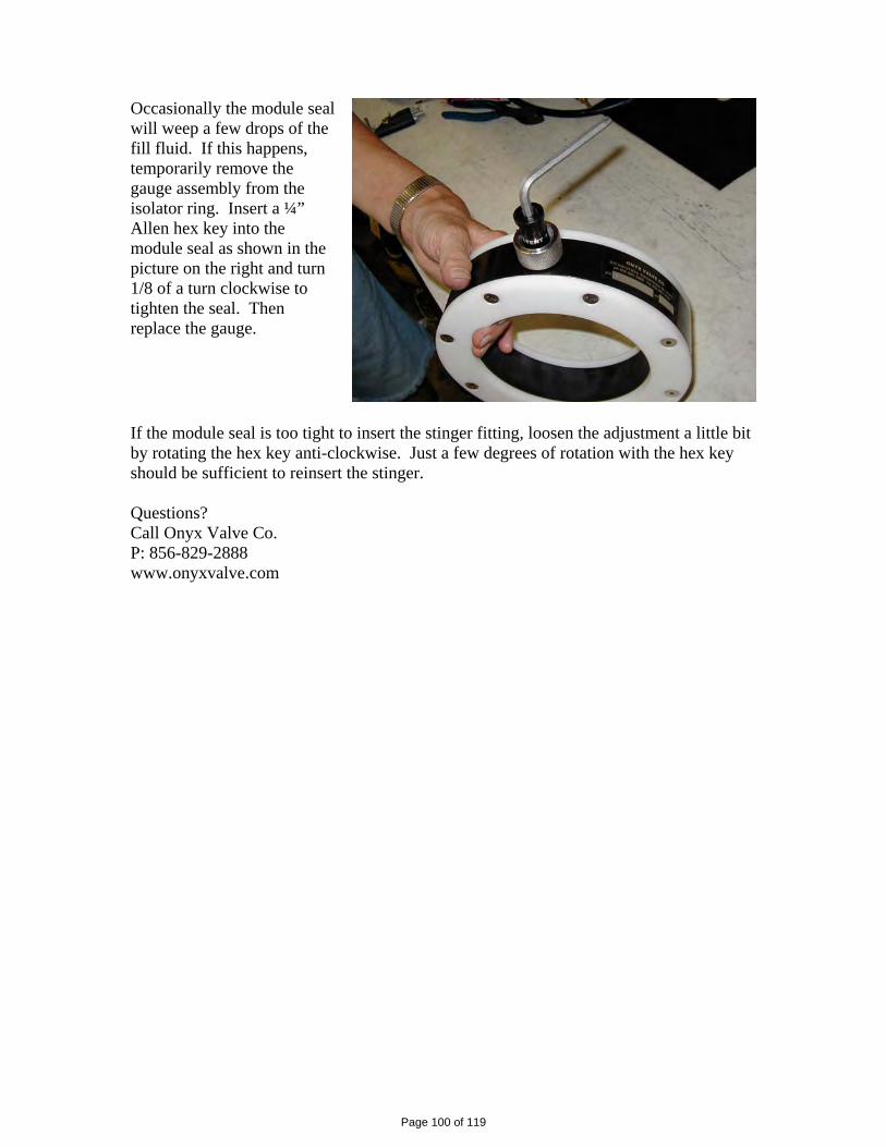
Occasionally the module seal will weep a few drops of the fill fluid. If this happens, temporarily remove the gauge assembly from the isolator ring. Insert a ¼” Allen hex key into the module seal as shown in the picture on the right and turn 1/8 of a turn clockwise to tighten the seal. Then replace the gauge.
If the module seal is too tight to insert the stinger fitting, loosen the adjustment a little bit by rotating the hex key anti-clockwise. Just a few degrees of rotation with the hex key should be sufficient to reinsert the stinger. Questions? Call Onyx Valve Co. P: 856-829-2888 www.onyxvalve.com
Page 100 of 119
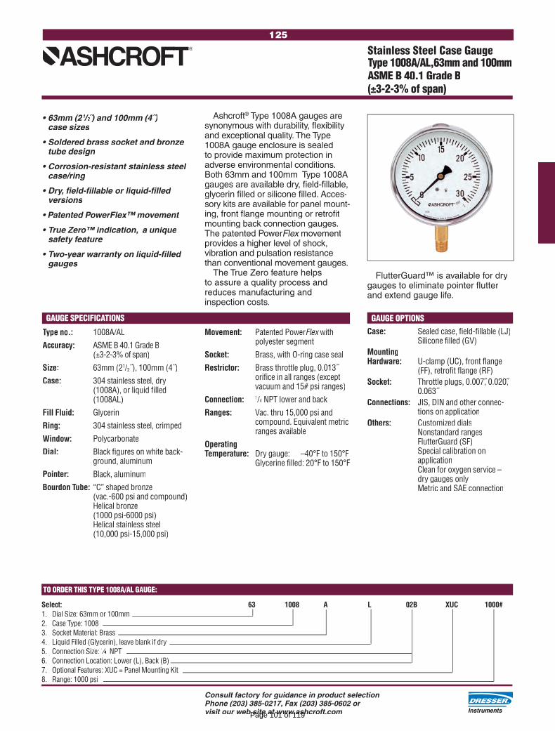
125
Consult factory for guidance in product selectionPhone (203) 385-0217, Fax (203) 385-0602 or visit our web site at www.ashcroft.com
TO ORDER THIS TYPE 1008A/AL GAUGE:
Select: 63 1008 A L 02B XUC 1000#1. Dial Size: 63mm or 100mm2. Case Type: 10083. Socket Material: Brass4. Liquid Filled (Glycerin), leave blank if dry5. Connection Size: 1⁄1⁄1 4⁄4⁄ NPT6. Connection Location: Lower (L), Back (B)7. Optional Features: XUC = Panel Mounting Kit8. Range: 1000 psi
Ashcroft® Type 1008A gauges are ® Type 1008A gauges are ®
synonymous with durability, fl exibility and exceptional quality. The Type 1008A gauge enclosure is sealed to provide maximum protection in adverse environmental conditions. Both 63mm and 100mm Type 1008A gauges are available dry, fi eld-fi llable, glycerin fi lled or silicone fi lled. Acces-sory kits are available for panel mount-ing, front fl ange mounting or retrofi t mounting back connection gauges. The patented PowerFlex movement Flex movement Flexprovides a higher level of shock, vibration and pulsation resistance than conventional movement gauges.
The True Zero feature helps to assure a quality process and reduces manufacturing and inspection costs.
• 63mm (21/1/1 2/2/ ˝) and 100mm (4˝)2 ) and 100mm (4˝)2
case sizes
• Soldered brass socket and bronze tube design
• Corrosion-resistant stainless steel case/ring
• Dry, fi eld-fi llable or liquid-fi lled versions
• Patented PowerFlex™ movement
• True Zero™ indication, a unique safety feature
• Two-year warranty on liquid-fi lled gauges
Stainless Steel Case GaugeType 1008A/AL,63mm and 100mmASME B 40.1 Grade B (±3-2-3% of span)
Type no.: 1008A/AL
Accuracy: ASME B 40.1 Grade B (±3-2-3% of span)
Size: 63mm (21/2˝), 100mm (4˝)
Case: 304 stainless steel, dry (1008A), or liquid fi lled (1008AL)
Fill Fluid: Glycerin
Ring: 304 stainless steel, crimped
Window: Polycarbonate
Dial: Black fi gures on white back-ground, aluminum
Pointer: Black, aluminum
Bourdon Tube: “C” shaped bronze (vac.-600 psi and compound)
Helical bronze (1000 psi-6000 psi)
Helical stainless steel(10,000 psi-15,000 psi)
GAUGE OPTIONSCase: Sealed case, fi eld-fi llable (LJ)
Silicone fi lled (GV)MountingHardware: U-clamp (UC), front fl ange
(FF), retrofi t fl ange (RF)Socket: Throttle plugs, 0.007, 0.020,
0.063˝Connections: JIS, DIN and other connec-
tions on applicationOthers: Customized dials Nonstandard ranges FlutterGuard (SF) Special calibration on
application Clean for oxygen service –
dry gauges only Metric and SAE connection
Movement: Patented PowerFlex with Flex with Flexpolyester segment
Socket: Brass, with O-ring case seal
Restrictor: Brass throttle plug, 0.013˝ orifi ce in all ranges (exceptvacuum and 15# psi ranges)
Connection: 1/4/4/ NPT lower and back
Ranges: Vac. thru 15,000 psi and compound. Equivalent metric ranges available
OperatingTemperature: Dry gauge: –40°F to 150°F
Glycerine fi lled: 20°F to 150°F
GAUGE SPECIFICATIONS
FlutterGuard™ is available for dry gauges to eliminate pointer fl utter and extend gauge life.
Page 101 of 119

211
Consult factory for guidance in product selectionPhone (203) 385-0217, Fax (203) 385-0602 or visit our web site at www.ashcroft.com
Code Process Code Process Range
& Temp.(6) Vac 0-600 1000 2000- Material Limits in.H2O psi psi 3000 °F psi B-Buna N 0 to 150
V-Viton 20 to 300
T-Tefl on 0 to 150
S-SS(5)(10) 0 to 300
P-Monel(5) 0 to 300
NOTES: 1. Standard switch. 2. Dual switches are 2 SPDT snap-action switches not
independently adjustable. 3. Estimated dc rating, 2.5A, 28 Vdc (not UL listed). 4. Estimated dc rating, .4A, 120 Vdc (not UL listed). 5. Available on pressure only. 6. Ambient operating temperature limits –20 to 150°F,
all styles. Setpoint shift of ±1% of range per 50°Fis normal. Switch calibrated at 70°F reference.
7. Items are wetted by process fl uid. 8. Refer to Option Table. 9. Order Option XUD, stainless steel process connection.10. On differential switches, stainless steel is available in 15, 30, 60 and 90 psid ranges only. Includes Tefl on O-ring and 316 SS connection.
TO ORDER THIS B-SERIES PRESSURE SWITCH:
Select: B4 20 B XPK 600 psi 1. Enclosure: 2. Switch Element: 3. Actuator Seal: 4. Options (See pages 229-230): 5. Pressure Range (See page 226):
Pressure and Differential Pressure Switches, Watertight Enclosure, Type 400, B-Series
• Choice of actuators, including designs for fi re-safe and NACE applications(8)
• Readily available
• Standard pressure connection materials:
Pressure psi ranges - 316L stainless steel
Differential psid ranges - Nickel-plated brass(9)
Pressure and differential inches of water ranges - Epoxy coated carbon steel
1 - ENCLOSUREB4 - Pressure switch, type 400, watertight
enclosure meets NEMA 3, 4, 4X and 13, IP66 requirements
D4 - Differential pressure switch, type 400, watertight enclosure meets NEMA 3, 4, 4X and 13, IP66 requirements
This general purpose Ashcroft®This general purpose Ashcroft®This general purpose Ashcroftswitch series is ideal for use in virtually all Industrial and OEM applications.
• Watertight NEMA 4X enclosure, IP66
• Choice of switch elements for all applications, including hermeti-cally sealed
• Wide choice of wetted materials, including all-welded Monel or stainless steel
• Fixed or limited adjustable deadband
• Approved for UL, CSA and FM(8)• Approved for UL, CSA and FM(8)• Approved for UL, CSA and FMratings
4 - OPTIONS(See pages 229-230)
5 - STANDARD PRESSURE RANGES(See page 226)
3 - ACTUATOR SEAL(7)
2 - SWITCH ELEMENTS Order Description/Maximum Electrical Ratings
Code UL/CSA Listed SPDT 20(4) Narrow deadband 15A, 125/250 Vac 21(9) Ammonia service 5A, 125/250 Vac Hermetically sealed 22(3) switch, narrow 5A, 125/250 Vac deadband 23 Heavy duty ac 20A,125/250 Vac 15A,125/250/480 Vac 24(1) General purpose 1/2A, 125 Vdc 1/4A, 250 Vdc 25 Heavy duty dc 10A,125/ Vac or dc 1/8HP 125/ Vac or dc 26(4) Sealed environment 15A, 125/250 Vac proof 27 High temp. 300°F 15A, 125/250 Vac 28 Manual reset trip 15A, 125/250 Vac on increasing 29 Manual reset trip 15A, 125/250 Vac on decreasing 31 Low level (gold) 1A,125/250 Vac contacts Hermetically sealed 32 switch, general 11A, 125/250 Vac purpose 5A, 30 Vdc 50 Variable deadband 15A,125/250 Vac UL/CSA Listed Dual SPDT(2)
61(4) Dual narrow deadband 15A, 125/250 Vac 62(4) Dual narrow environ- 15A, 125/250 Vac ment proof 63 Dual high temp. 300°F 15A, 125/250 Vac 15A,125/250/480 Vac 64 Dual general purpose 1/2A, 125 Vdc 1/4A, 250 Vdc 65 Dual ammonia service 5A, 125/250/480
HERMETICALLY SEALED SWITCHWe recommend hermetically sealed switch elements for improved reliability. The hermetically sealed switch provides uncompromising contact protection in harsh or corrosive environments. The Ashcroft 400 Series is also approved for installation in Division II hazardous areas when supplied with hermetically sealed contacts.Features:• UL-recognized component,
guide WSQ2, File E85076• All-stainless steel welded
construction
LOOK FOR THIS AGENCY MARK ON OUR PRODUCTS
Page 102 of 119

230Series
The Expansion Joint People
PROCO PRODUCTS, INC.
Page 103 of 119

Protecting Piping AndEquipment SystemsFrom Stress / Motion
spool type wide archrubber expansion joints
230/220SERIES
PROCO Series 230, Styles 231, 232, & 233 Non-Metallic Expansion Joints are designedfor tough, demanding industrial applications, as found in: Chemical/Petrochemical Plants,Industrial Process Piping Systems, Marine Services, Power Generation Plants, Pulp/Paper Plants, Steel Mills, Water/Wastewater and Pollution Control Systems. Installednext to mechanical equipment or between the anchor points of a piping system, specifythe PROCO Series 230 to: (1) Absorb Pipe Movement/Stress, (2) Reduce System Noise,(3) Isolate Mechanical Vibration, (4) Compensate Alignment/Offset, (5) Eliminate Elec-trolysis, (6) Protect Against Start-Up Surge Forces. Our history in the manufacture ofexpansion joints dates back to l930. When you need an engineered rubber expansionjoint solution to a piping problem, call PROCO!Series 230 Replaces Series 220. The new and improved PROCO Series 230 replaces thePROCO Series 220 rubber expansion joints. (Series 220 products will be available only inshort neutral lengths.) This new hand-built product has been completely re-engineered toprovide improved strength, flexibility, movement and spring rate capabilities. Manufac-tured utilizing tire industry technology, the Series 230 combines woven nylon fabric andnylon tire cord into a fabric matrix bonded with elastomer and reinforced with wire tocreate a product with greater operating performance. The nomenclature for the new PROCOSeries 230 is as follows:
Single Arch Series 230, Style 231Double Arch Series 230, Style 232Triple Arch Series 230, Style 233
Greater Movements With A Lower/Wider Arch Profile. The movements for the PROCOSeries 230 exceed the specification of the Fluid Sealing Association's Rubber ExpansionJoint Division Technical Handbook (Sixth Edition), Table V. Due to a new and improvedlower, wider profile arch, more axial compression and axial extension coupled with lateralmisalignment, angular and torsional movements can be obtained without increasing theface-to-face requirements. Installation of the Series 230 in a piping system will negate theneed for long and expensive multi-arch products. For greater movements based on re-engineering and new product construction, specify the PROCO Series 230.Less Turbulence Or Material Entrapment. The PROCO 230 Series molded integral flangejoins the body at a true 90° angle. Our product will install snug against the mating pipeflange without voids. The flange body of the rubber expansion joint is difficult to form andmany manufacturers radius the edge angles. The resulting void between the mating flangeand the edge angle can create flow turbulence and allow for material entrapment orbacterial growth. You can avoid these problems by specifying PROCO Series 230 rubberexpansion joints.Chemical Or Abrasive Service Capability. Expensive metallic designs for chemical ser-vice can be replaced with the more cost-effective PROCO Series 230. Built with low-costchemical resistant elastomers, such as Chlorobutyl, DuPont Dow Elastomer Hypalon ®
rubber, EPDM, Natural, Neoprene and Nitrile, assures an expansion joint compatible withfluid being pumped or piped (See Table 1). When handling abrasive products such as anysolids or slurries, Natural or Neoprene filled arch products should be specified. Pleaserefer to PROCO "Chemical to Elastomer Guide" for recommendations on elastomer chemicalcompatibility for piping processes.
Exclusive Sealing Bead Means A Quick Seal. PROCO has built an "O-Ring" on eachflange face of the Series 230. Available only from PROCO, the Series 230 seals faster withless torque at installation. For these exclusive features, specify the PROCO Series 230rubber expansion joints.Specifications Met. PROCO has assigned conservative pressure ratings to the Series230 rubber expansion joints. The ratings, however, meet the requirements of the FluidSealing Association's Rubber Expansion Joint Division Technical Handbook (Sixth Edi-tion), Series C. The pressure ratings for the Series 230 rubber expansion joints have beenfully tested and are based on a minimum four-to-one safety factor. For pressure protec-tion with confidence, specify the PROCO Series 230.Tested Force Pound And Spring Rate Tables. The Series 230 rubber expansion jointsare in accordance with and/or lower than the guidelines for spring rate data as listed inthe Fluid Sealing Association's Rubber Expansion Joint Division Technical Handbook(Sixth Edition), Table V. Due to a lower, wider arch profile, the PROCO Series 230 willprovide more flexibility than conventional spool-type rubber expansion joints. In addi-tion, the lower/wider arch profile coupled with a modified radial tire cord constructionwill result in lower flange forces. Lower resultant forces mean reduced stress of relatedpiping system components. PROCO is currently testing each rubber expansion jointsize and will list actual test data as opposed to listing hypothetical data normally asso-ciated with spring rate tables.Absorbs Vibration • Noise • Shock. The PROCO Series 230 quiet-operating rubber ex-pansion joints are a replacement for "sound transmitting" metallic expansion joints. Soundloses energy traveling axially through an expansion joint. Water hammer, pumping im-pulses, water-borne noises and other forms of strain-stress-shock are cushioned andabsorbed by the molded elastomer expansion joint, not related to piping. Install the Se-ries 230 in a system to reduce vibration transmission when the piping section beyond theexpansion joint is anchored or sufficiently rigid. For quiet, stress-free systems, specifythe PROCO Series 230.Wide Service Range With Low Cost. Engineered to operate up to 200 PSIG or up to250°F, the PROCO Series 230 can be specified for a wide range of piping system require-ments. Compared to competitive products, you will invest less money when specifyingthe engineered design and industrial quality of the PROCO Series 230.Large Inventory Means Same-Day Shipment. We maintain the largest inventory ofelastomeric expansion joints in the world. Every size cataloged up to 72" is in stockin a variety of elastomers. We can ship the products you need when you need them!In fact, when it comes to rubber expansion joints, if PROCO doesn't have them instock … nobody does!Information • Ordering • Pricing • Delivery. Day or night, weekends and holidays … thePROCO phones are monitored 24 hours around the clock. When you have a question, youcan call us.
Toll-Free Phone .......... 800 / 344-3246 USA/CANADAInternational Calls ...... 209 / 943-6088Fax ............................. 209 / 943-0242E-mail ......................... [email protected] Site ..................... www.procoproducts.comWeekday office hours are 5:30 a.m. to 5:15 p.m. Pacific Time.
Notes: Hypalon ® is a registered trademark of DuPont Dow Elastomers.All products are reinforced with steel and fabric materials.1. Style numbers above reflect one arch. Products are also available in Styles 232 and 233.2. Expansion joint "cover" can be coated with Hypalon ® on special order.3. Styles with Neoprene covers meet all requirements of U.S.C.G.
PROCO Style Numbers
Table 1: Available Styles • Materials • TemperaturesFor Specific ElastomerRecommendations, See: PROCO™ “Chemical To Elastomer Guide”
Open Arch(Single) 1
Cover 2, 3
Elastomer
MaximumOperating
Temp. °F (°C)
BrandingLabelColor
F.S.A.Material
ClassFilled Arch(Single) 1
TubeElastomer
250° (121°)250° (121°)212° (100°)225° (107°)212° (100°)180° (82°)
FA231/BBFA231/EEFA231/NHFA231/NNFA231/NPFA231/NR
231/BB231/EE231/NH231/NN231/NP231/NR
ChlorobutylEPDM
NeopreneNeopreneNeopreneNeoprene
BlackRed
GreenBlue
YellowWhite
STD. IIISTD. IIISTD. IISTD. IISTD. IISTD. I
ChlorobutylEPDM
Hypalon®
NeopreneNitrile
NaturalSeries 230Page 2 of 10Rev. 06 04/10 PDF
Page 104 of 119

single wide arch spool typerubber expansion joints
231/221STYLE
Table 2: Sizes • Movements • Forces • Weights See Notes Page 7
EXPA
NSIO
NJO
INT
SIZE
Nom
. I.D
. xIn
ch /
(mm
)
NEUT
RAL
LENG
THIn
ch /
(mm
)
EXPA
NSIO
NJO
INT
STYL
E
231 / 221 Movement Capability:From Neutral Position
Axia
lCo
mpr
essi
onIn
ch /
(mm
)
Axia
lEx
tens
ion
Inch
/ (m
m)
Late
ral
Defle
ctio
nIn
ch /
(mm
)
Angu
lar1
Defle
ctio
n De
gree
s
Tors
iona
l 2
Rota
tion
Degr
ees
Spring Rate Capability Based on 1" ofMovement at Zero Pressure Conditions
Forc
e lb
spe
r 1" r
ated
Com
pres
sion
Thru
st F
acto
r3
In2
/ (cm
2)
Forc
e lb
spe
r 1" r
ated
Exte
nsio
n
Forc
e lb
spe
r 1" r
ated
Latre
ral D
efle
ctio
n
Forc
e ft-
lbs
per 1
° rat
edAn
gula
r
Posi
tive
PSIG
/(B
ar)
Reta
inin
gRi
ng S
et
Cont
rol6
Rod
Asse
mbl
y
Vacu
umIn
ches
of H
g/(m
m o
f Hg)
Expa
nsio
nJo
int
Asse
mbl
y
Operating 4
ConditionsWeights 5
lbs / (kgs)
6 (152) 231
6 (152) 231
6 (152) 231
6 (152) 231
7 (178) 2318 (203) 2319 (229) 231
10 (254) 23112 (305) 2316 (152) 2317 (178) 2318 (203) 2319 (229) 231
10 (254) 23112 (305) 2316 (152) 2317 (178) 2318 (203) 2319 (229) 231
10 (254) 23112 (305) 2316 (152) 2217 (178) 2218 (203) 2219 (229) 221
10 (254) 22112 (305) 2216 (152) 2317 (178) 2318 (203) 2319 (229) 231
10 (254) 23112 (305) 231
1 (25)
1.25 (32)
1.5 (40)
2 (50)
2.5 (65)
3 (80)
3.5 (90)
4 (100)
See Notes Page 7
U
N
D
E
R
C
U
R
R
E
N
T
T
E
S
T
I
N
G
1.2 0.6 0.6 50.4 2.0 5.12 200 26 2.0 2.0 2.3(30) (15) (15) (33) (14.0) (660) (0.8) (0.8) (1.0)
1.2 0.6 0.6 43.1 2.0 6.20 200 26 2.5 2.5 2.3(30) (15) (15) (40) (14.0) (660) (1.1) (1.1) (1.0)
1.2 0.6 0.6 38.1 2.0 7.44 200 26 3.0 2.5 2.3(30) (15) (15) (48) (14.0) (660) (1.4) (1.1) (1.0)
1.4 0.7 0.6 34.2 2.0 12.40 200 26 4.0 4.0 2.8(35) (18) (15) (80) (14.0) (660) (1.8) (1.8) (1.3)
1.4 0.7 0.6 27.6 2.0 15.66 200 26 4.5 4.5 2.8(35) (18) (15) (101) (14.0) (660) (2.0) (2.0) (1.3)
1.4 0.7 0.6 23.0 2.0 19.38 200 26 5.5 5.5 2.8(35) (18) (15) (125) (14.0) (660) (2.5) (2.5) (1.3)
0.6 0.3 0.56 9.0 2.0 23.18 200 26 6.0 6.0 2.8(15) (8) (14) (150) (14.0) (660) (2.7) (2.7) (1.3)
1.4 0.7 0.6 18.8 2.0 27.90 200 26 8.0 8.0 2.8(35) (18) (15) (180) (14.0) (660) (3.6) (3.6) (1.3)
Series 230Page 3 of 16
Page 105 of 119
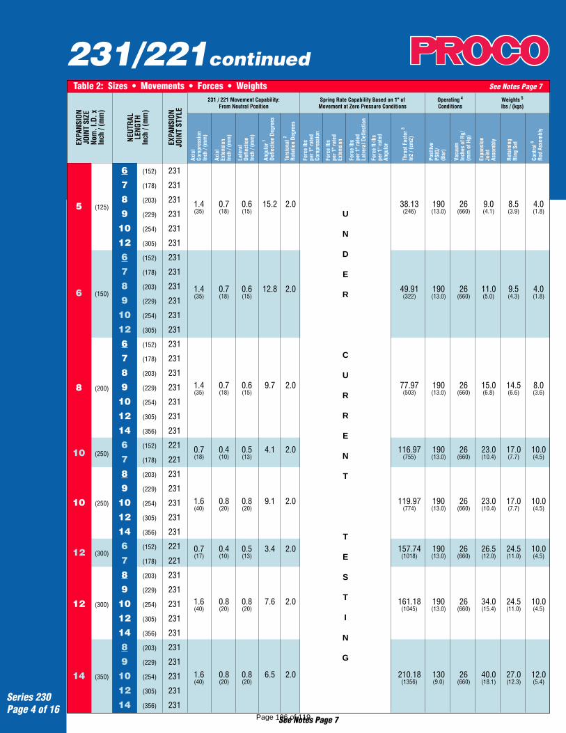
231/221continuedTable 2: Sizes • Movements • Forces • Weights See Notes Page 7
EXPA
NSIO
NJO
INT
SIZE
Nom
. I.D
. xIn
ch /
(mm
)
NEUT
RAL
LENG
THIn
ch /
(mm
)
EXPA
NSIO
NJO
INT
STYL
E
231 / 221 Movement Capability:From Neutral Position
Axia
lCo
mpr
essi
onIn
ch /
(mm
)
Axia
lEx
tens
ion
Inch
/ (m
m)
Late
ral
Defle
ctio
nIn
ch /
(mm
)
Angu
lar1
Defle
ctio
n De
gree
s
Tors
iona
l 2
Rota
tion
Degr
ees
Spring Rate Capability Based on 1" ofMovement at Zero Pressure Conditions
Forc
e lb
spe
r 1" r
ated
Com
pres
sion
Thru
st F
acto
r3
In2
/ (cm
2)
Forc
e lb
spe
r 1" r
ated
Exte
nsio
n
Forc
e lb
spe
r 1" r
ated
Latre
ral D
efle
ctio
n
Forc
e ft-
lbs
per 1
° rat
edAn
gula
r
Posi
tive
PSIG
/(B
ar)
Reta
inin
gRi
ng S
et
Cont
rol6
Rod
Asse
mbl
y
Vacu
umIn
ches
of H
g/(m
m o
f Hg)
Expa
nsio
nJo
int
Asse
mbl
y
Operating 4
ConditionsWeights 5
lbs / (kgs)
U
N
D
E
R
C
U
R
R
E
N
T
T
E
S
T
I
N
G
See Notes Page 7
5 (125)
6 (150)
8 (200)
10 (250)
10 (250)
12 (300)
12 (300)
14 (350)
6 (152) 231
7 (178) 231
8 (203) 231
9 (229) 231
10 (254) 231
12 (305) 231
6 (152) 231
7 (178) 231
8 (203) 231
9 (229) 231
10 (254) 231
12 (305) 231
6 (152) 231
7 (178) 231
8 (203) 231
9 (229) 231
10 (254) 231
12 (305) 231
14 (356) 231
6 (152) 221
7 (178) 221
8 (203) 231
9 (229) 231
10 (254) 231
12 (305) 231
14 (356) 231
6 (152) 221
7 (178) 221
8 (203) 231
9 (229) 231
10 (254) 231
12 (305) 231
14 (356) 231
8 (203) 231
9 (229) 231
10 (254) 231
12 (305) 231
14 (356) 231
1.4 0.7 0.6 15.2 2.0 38.13 190 26 9.0 8.5 4.0(35) (18) (15) (246) (13.0) (660) (4.1) (3.9) (1.8)
1.4 0.7 0.6 12.8 2.0 49.91 190 26 11.0 9.5 4.0(35) (18) (15) (322) (13.0) (660) (5.0) (4.3) (1.8)
1.4 0.7 0.6 9.7 2.0 77.97 190 26 15.0 14.5 8.0(35) (18) (15) (503) (13.0) (660) (6.8) (6.6) (3.6)
0.7 0.4 0.5 4.1 2.0 116.97 190 26 23.0 17.0 10.0(18) (10) (13) (755) (13.0) (660) (10.4) (7.7) (4.5)
1.6 0.8 0.8 9.1 2.0 119.97 190 26 23.0 17.0 10.0(40) (20) (20) (774) (13.0) (660) (10.4) (7.7) (4.5)
0.7 0.4 0.5 3.4 2.0 157.74 190 26 26.5 24.5 10.0(17) (10) (13) (1018) (13.0) (660) (12.0) (11.0) (4.5)
1.6 0.8 0.8 7.6 2.0 161.18 190 26 34.0 24.5 10.0(40) (20) (20) (1045) (13.0) (660) (15.4) (11.0) (4.5)
1.6 0.8 0.8 6.5 2.0 210.18 130 26 40.0 27.0 12.0(40) (20) (20) (1356) (9.0) (660) (18.1) (12.3) (5.4)
Series 230Page 4 of 16
Page 106 of 119

231/221continuedTable 2: Sizes • Movements • Forces • Weights See Notes Page 7
EXPA
NSIO
NJO
INT
SIZE
Nom
. I.D
. xIn
ch /
(mm
)
NEUT
RAL
LENG
THIn
ch /
(mm
)
EXPA
NSIO
NJO
INT
STYL
E
231 / 221 Movement Capability:From Neutral Position
Axia
lCo
mpr
essi
onIn
ch /
(mm
)
Axia
lEx
tens
ion
Inch
/ (m
m)
Late
ral
Defle
ctio
nIn
ch /
(mm
)
Angu
lar1
Defle
ctio
n De
gree
s
Tors
iona
l 2
Rota
tion
Degr
ees
Spring Rate Capability Based on 1" ofMovement at Zero Pressure Conditions
Forc
e lb
spe
r 1" r
ated
Com
pres
sion
Thru
st F
acto
r3
In2
/ (cm
2)
Forc
e lb
spe
r 1" r
ated
Exte
nsio
n
Forc
e lb
spe
r 1" r
ated
Latre
ral D
efle
ctio
n
Forc
e ft-
lbs
per 1
° rat
edAn
gula
r
Posi
tive
PSIG
/(B
ar)
Reta
inin
gRi
ng S
et
Cont
rol6
Rod
Asse
mbl
y
Vacu
umIn
ches
of H
g/(m
m o
f Hg)
Expa
nsio
nJo
int
Asse
mbl
y
Operating 4
ConditionsWeights 5
lbs / (kgs)
U
N
D
E
R
C
U
R
R
E
N
T
T
E
S
T
I
N
G
See Notes Page 7
8 (203) 231
9 (229) 231
10 (254) 231
12 (305) 231
14 (356) 231
8 (203) 231
9 (229) 231
10 (254) 231
12 (305) 231
14 (356) 231
8 (203) 231
9 (229) 231
10 (254) 231
12 (305) 231
14 (356) 231
8 (203) 221
9 (229) 221
10 (254) 231
12 (305) 231
14 (356) 231
8 (203) 221
9 (229) 221
10 (254) 231
12 (305) 231
14 (356) 231
10 (254) 231
12 (305) 231
14 (356) 231
10 (254) 231
12 (305) 231
14 (356) 231
9 (229) 221
10 (254) 231
12 (305) 231
14 (356) 231
16 (400)
18 (450)
20 (500)
22 (550)
22 (550)
24 (600)
24 (600)
26 (650)
28 (700)
30 (750)
30 (750)
1.6 0.8 0.8 5.7 2.0 264.74 115 26 47.0 33.5 15.0(40) (20) (20) (1708) (8.0) (660) (21.3) (15.2) (6.8)
1.6 0.8 0.8 5.1 2.0 325.50 115 26 56.0 34.0 16.0(40) (20) (20) (2100) (8.0) (660) (25.4) (15.5) (7.2)
1.6 0.8 0.8 5.7 2.0 392.62 115 26 67.0 38.0 16.0(40) (20) (20) (2533) (8.0) (660) (30.4) (17.3) (7.2)
0.8 0.5 0.5 2.6 2.0 483.08 100 26 70.0 44.0 19.0(20) (13) (13) (3117) (7.0) (660) (31.8) (20.0) (8.6)
2.0 1.0 1.0 5.2 2.0 481.12 100 26 70.0 44.0 19.0(51) (25) (25) (3104) (7.0) (660) (31.8) (20.0) (8.6)
0.8 0.5 0.5 2.3 2.0 562.82 100 26 79.0 48.0 19.0(20) (13) (13) (3631) (7.0) (660) (35.8) (21.8) (8.6)
2.0 1.0 1.0 4.8 2.0 562.03 100 26 79.0 48.0 20.0(51) (25) (25) (3626) (7.0) (660) (35.8) (21.8) (9.0)
2.0 1.0 1.0 4.4 2.0 649.14 90 26 100.0 51.0 20.0(51) (25) (25) (4188) (6.0) (660) (45.4) (23.1) (9.0)
2.0 1.0 1.0 4.1 2.0 742.45 90 26 102.0 55.0 28.0(51) (25) (25) (4790) (6.0) (660) (46.3) (25.0) (12.6)
0.9 0.6 0.5 2.2 2.0 798.58 90 26 117.0 63.0 29.5(23) (15) (13) (5152) (6.0) (660) (53.1) (28.6) (13.3)
2.0 1.0 1.0 3.8 2.0 842.27 90 26 117.0 63.0 29.5(51) (25) (25) (5434) (6.0) (660) (53.1) (28.6) (13.3)Series 230
Page 5 of 16Page 107 of 119
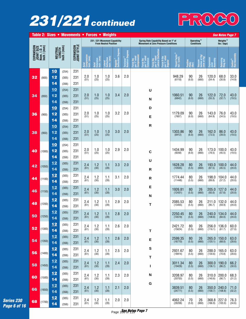
231/221continued
Series 230Page 6 of 16
2.0 1.0 1.0 3.6 2.0 948.29 90 26 120.0 68.0 33.0(51) (25) (25) (6118) (6.0) (660) (54.4) (30.8) (14.9)
2.0 1.0 1.0 3.4 2.0 1060.51 90 26 122.0 72.0 43.0(51) (25) (25) (6842) (6.0) (660) (55.3) (32.7) (19.5)
2.0 1.0 1.0 3.2 2.0 1179.09 90 26 143.0 76.0 43.0(51) (25) (25) (7607) (6.0) (660) (64.9) (34.5) (19.5)
2.0 1.0 1.0 3.0 2.0 1303.86 90 26 162.0 86.0 43.0(51) (25) (25) (8412) (6.0) (660) (73.5) (39.0) (19.5)
2.0 1.0 1.0 2.9 2.0 1434.99 90 26 173.0 100.0 43.0(51) (25) (25) (9258) (6.0) (660) (78.5) (45.5) (19.5)
2.4 1.2 1.1 3.3 2.0 1628.28 80 26 193.0 100.0 44.0(61) (30) (28) (10505) (5.5) (660) (87.5) (45.5) (20.0)
2.4 1.2 1.1 3.1 2.0 1774.44 80 26 198.0 104.0 44.0(61) (30) (28) (11448) (5.5) (660) (89.8) (37.2) (20.0)
2.4 1.2 1.1 3.0 2.0 1926.81 80 26 205.0 127.0 44.0(61) (30) (28) (12431) (5.5) (660) (93.0) (57.6) (20.0)
2.4 1.2 1.1 2.9 2.0 2085.53 80 26 211.0 132.0 44.0(61) (30) (28) (13455) (5.5) (660) (95.7) (59.9) (20.0)
2.4 1.2 1.1 2.8 2.0 2250.45 80 26 240.0 134.0 44.0(61) (30) (28) (14519) (5.5) (660) (108.8) (60.0) (20.0)
2.4 1.2 1.1 2.6 2.0 2421.72 80 26 256.0 136.0 60.0(61) (30) (28) (15624) (5.5) (660) (116.1) (61.7) (27.0)
2.4 1.2 1.1 2.6 2.0 2599.35 80 26 265.0 150.0 63.0(61) (30) (28) (16770) (5.5) (660) (120.1) (68.0) (28.6)
2.4 1.2 1.1 2.5 2.0 2931.67 80 26 288.0 165.0 63.0(61) (30) (28) (18914) (5.5) (660) (130.6) (70.8) (28.6)
2.4 1.2 1.1 2.4 2.0 3011.34 80 26 300.0 190.0 66.2(61) (30) (28) (19428) (5.5) (660) (136.1) (86.2) (30.0)
2.4 1.2 1.1 2.3 2.0 3208.97 80 26 310.0 200.0 68.3(61) (30) (28) (20703) (5.5) (660) (140.6) (90.7) (31.2)
2.4 1.2 1.1 2.1 2.0 3839.51 80 26 350.0 240.0 71.0(61) (30) (28) (24771) (5.5) (660) (158.7) (108.8) (32.2)
2.4 1.2 1.1 2.0 2.0 4062.24 70 26 368.8 227.0 76.3(61) (30) (28) (28208) (5.0) (660) (166.9) (103.0) (34.6)
Table 2: Sizes • Movements • Forces • Weights See Notes Page 7EX
PANS
ION
JOIN
T SI
ZENo
m. I
.D. x
Inch
/ (m
m)
NEUT
RAL
LENG
THIn
ch /
(mm
)
EXPA
NSIO
NJO
INT
STYL
E
231 / 221 Movement Capability:From Neutral Position
Axia
lCo
mpr
essi
onIn
ch /
(mm
)
Axia
lEx
tens
ion
Inch
/ (m
m)
Late
ral
Defle
ctio
nIn
ch /
(mm
)
Angu
lar1
Defle
ctio
n De
gree
s
Tors
iona
l 2
Rota
tion
Degr
ees
Spring Rate Capability Based on 1" ofMovement at Zero Pressure Conditions
Forc
e lb
spe
r 1" r
ated
Com
pres
sion
Thru
st F
acto
r3
In2
/ (cm
2)
Forc
e lb
spe
r 1" r
ated
Exte
nsio
n
Forc
e lb
spe
r 1" r
ated
Latre
ral D
efle
ctio
n
Forc
e ft-
lbs
per 1
° rat
edAn
gula
r
Posi
tive
PSIG
/(B
ar)
Reta
inin
gRi
ng S
et
Cont
rol6
Rod
Asse
mbl
y
Vacu
umIn
ches
of H
g/(m
m o
f Hg)
Expa
nsio
nJo
int
Asse
mbl
y
Operating 4
ConditionsWeights 5
lbs / (kgs)
U
N
D
E
R
C
U
R
R
E
N
T
T
E
S
T
I
N
G
See Notes Page 7
32 (800)
34 (850)
36 (900)
38 (950)
40 (1000)
42 (1050)
44 (1100)
46 (1150)
48 (1200)
50 (1250)
52 (1300)
54 (1350)
56 (1400)
58 (1450)
60 (1500)
66 (1650)
68 (1700)
10 (254) 231
12 (305) 231
14 (356) 231
10 (254) 231
12 (305) 231
14 (356) 231
10 (254) 231
12 (305) 231
14 (356) 231
10 (254) 231
12 (305) 231
14 (356) 231
10 (254) 231
12 (305) 231
14 (356) 231
12 (305) 231
14 (356) 231
12 (305) 231
14 (356) 231
12 (305) 231
14 (356) 231
12 (305) 231
14 (356) 231
12 (305) 231
14 (356) 231
12 (305) 231
14 (356) 231
12 (305) 231
14 (356) 231
12 (305) 231
14 (356) 231
12 (305) 231
14 (356) 231
12 (305) 231
14 (356) 231
12 (305) 231
14 (356) 231
12 (305) 231
14 (356) 231
Page 108 of 119

231/221continued
Neutral lengths underlined are the recommended minimum lengths.Metric Conversion Formula: Nominal I.D.: in. x 25 = mm; Dimensions: in. x 25.4 = mm; Pressure: PSIG x .069 = BarNOTES:1. The degree of angular movement is based on the maximum rated extension.2. Torsional movement is expressed when the expansion joint is at its neutral length.3. To determine "end thrust", multiply thrust factor by operating pressure of system.4. Pressure rating is based on 170°F operating temperature with a 4:1 safety factor. At higher temperatures, the
pressure rating is reduced slightly. Hydrostatic testing at 1.5 times rated or working pressure for 10 minutes isavailable upon request.
5. Weights are approximate and vary due to OAL.6. Control rod unit weight consists of one rod with washers, nuts and two control rod plates. Multiply number of control rods
needed for application (as specified in the Fluid Sealing Association's Technical Handbook) to determine correct weights.
Filled Arch Rubber Expansion JointsKnown as Style FA231 or Style FA221 the Series FA230Rubber Expansion Joints are designed to eliminate flowturbulence and collection of solids in the arch core.Filled Arch Rubber Expansion Joints can be found inapplications such as sludge, slurries or other heavysolids where material entrapment, high flow velocity orhigh abrasion conditions exist. Filled arch products aremanufactured with seamless tube and are built as anintegral part of the carcass. Although the tube is madeof a low durometer filler stock, movement ratings of theStyle FA231 or Style FA221 are 50% less than thosemovements listed in the table above. PROCO can manu-facture any size listed in the table above.
FA231Single Filled Arch
Toll Free Phone . . . . . . . . . . (800) 344-3246International Calls . . . . . . . . (209) 943-6088Facsimile . . . . . . . . . . . . . . (209) 943-0242E-mail . . . . . . . . . [email protected] Site . . . . http://www.procoproducts.com
Series 230Page 7 of 16
Table 2: Sizes • Movements • Forces • Weights See Notes BelowEX
PANS
ION
JOIN
T SI
ZENo
m. I
.D. x
Inch
/ (m
m)
NEUT
RAL
LENG
THIn
ch /
(mm
)
EXPA
NSIO
NJO
INT
STYL
E
231 / 221 Movement Capability:From Neutral Position
Axia
lCo
mpr
essi
onIn
ch /
(mm
)
Axia
lEx
tens
ion
Inch
/ (m
m)
Late
ral
Defle
ctio
nIn
ch /
(mm
)
Angu
lar1
Defle
ctio
n De
gree
s
Tors
iona
l 2
Rota
tion
Degr
ees
Spring Rate Capability Based on 1" ofMovement at Zero Pressure Conditions
Forc
e lb
spe
r 1" r
ated
Com
pres
sion
Thru
st F
acto
r3
In2
/ (cm
2)
Forc
e lb
spe
r 1" r
ated
Exte
nsio
n
Forc
e lb
spe
r 1" r
ated
Latre
ral D
efle
ctio
n
Forc
e ft-
lbs
per 1
° rat
edAn
gula
r
Posi
tive
PSIG
/(B
ar)
Reta
inin
gRi
ng S
et
Cont
rol6
Rod
Asse
mbl
y
Vacu
umIn
ches
of H
g/(m
m o
f Hg)
Expa
nsio
nJo
int
Asse
mbl
y
Operating 4
ConditionsWeights 5
lbs / (kgs)
UNDER
CURRENT
TESTING
72 (1800)
78 (1950)
84 (2100)
90 (2250)
96 (2400)
102 (2550)
108 (2700)
120 (3000)
12 (305) 231
14 (356) 231
12 (305) 231
14 (356) 231
12 (305) 231
14 (356) 231
12 (305) 231
14 (356) 231
12 (305) 231
14 (356) 231
12 (305) 231
14 (356) 231
12 (305) 231
14 (356) 231
12 (305) 231
14 (356) 231
2.4 1.2 1.1 1.9 2.0 4526.62 70 26 390.0 290.0 87.0(61) (30) (28) (29244) (5.0) (660) (176.9) (131.5) (39.4)
2.3 1.2 1.0 1.8 2.0 5410.60 85 26 410.0 315.0 103.0(57) (30) (25) (34907) (6.0) (660) (186.0) (142.9) (46.7)
2.3 1.2 1.0 1.6 2.0 6221.13 85 26 440.0 350.0 113.0(57) (30) (25) (40136) (6.0) (660) (200.0) (158.0) (51.3)
2.3 1.2 1.0 1.6 2.0 7088.11 85 26 448.0 363.0 125.0(57) (30) (25) (45730) (6.0) (660) (203.1) (164.6) (56.7)
2.3 1.2 1.0 1.4 2.0 8011.85 85 26 466.0 367.0 125.0(57) (30) (25) (51689) (6.0) (660) (211.3) (170.5) (56.7)
2.3 1.2 1.0 1.3 2.0 8992.02 85 26 485.8 395.0 137.0(57) (30) (25) (58013) (6.0) (660) (220.0) (179.1) (62.1)
2.3 1.2 1.1 1.2 2.0 10028.75 85 26 510.0 425.0 139.0(57) (30) (28) (64702) (6.0) (660) (231.3) (192.7) (63.0)
2.3 1.2 1.0 1.1 2.0 12271.84 85 26 540.0 565.0 151.0(57) (30) (25) (79173) (6.0) (660) (244.9) (256.2) (65.8)
Page 109 of 119
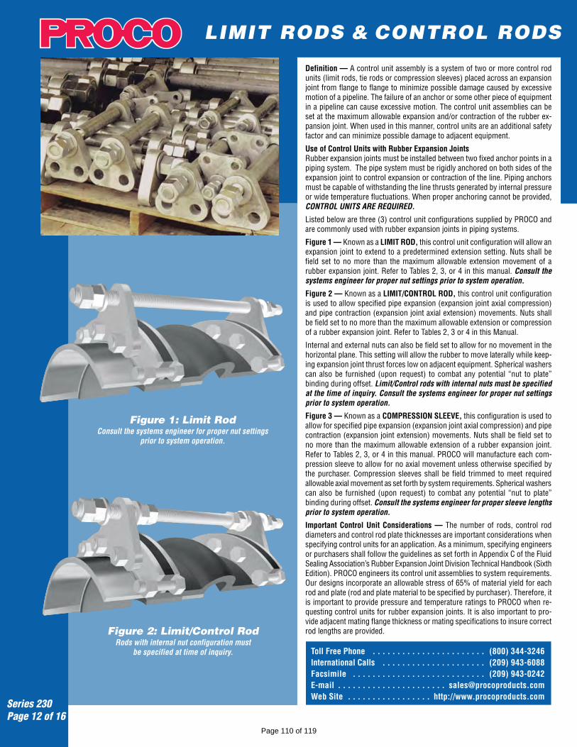
Definition — A control unit assembly is a system of two or more control rodunits (limit rods, tie rods or compression sleeves) placed across an expansionjoint from flange to flange to minimize possible damage caused by excessivemotion of a pipeline. The failure of an anchor or some other piece of equipmentin a pipeline can cause excessive motion. The control unit assemblies can beset at the maximum allowable expansion and/or contraction of the rubber ex-pansion joint. When used in this manner, control units are an additional safetyfactor and can minimize possible damage to adjacent equipment.
Use of Control Units with Rubber Expansion JointsRubber expansion joints must be installed between two fixed anchor points in apiping system. The pipe system must be rigidly anchored on both sides of theexpansion joint to control expansion or contraction of the line. Piping anchorsmust be capable of withstanding the line thrusts generated by internal pressureor wide temperature fluctuations. When proper anchoring cannot be provided,CONTROL UNITS ARE REQUIRED.
Listed below are three (3) control unit configurations supplied by PROCO andare commonly used with rubber expansion joints in piping systems.
Figure 1 — Known as a LIMIT ROD, this control unit configuration will allow anexpansion joint to extend to a predetermined extension setting. Nuts shall befield set to no more than the maximum allowable extension movement of arubber expansion joint. Refer to Tables 2, 3, or 4 in this manual. Consult thesystems engineer for proper nut settings prior to system operation.
Figure 2 — Known as a LIMIT/CONTROL ROD, this control unit configurationis used to allow specified pipe expansion (expansion joint axial compression)and pipe contraction (expansion joint axial extension) movements. Nuts shallbe field set to no more than the maximum allowable extension or compressionof a rubber expansion joint. Refer to Tables 2, 3 or 4 in this Manual.
Internal and external nuts can also be field set to allow for no movement in thehorizontal plane. This setting will allow the rubber to move laterally while keep-ing expansion joint thrust forces low on adjacent equipment. Spherical washerscan also be furnished (upon request) to combat any potential “nut to plate”binding during offset. Limit/Control rods with internal nuts must be specifiedat the time of inquiry. Consult the systems engineer for proper nut settingsprior to system operation.
Figure 3 — Known as a COMPRESSION SLEEVE, this configuration is used toallow for specified pipe expansion (expansion joint axial compression) and pipecontraction (expansion joint extension) movements. Nuts shall be field set tono more than the maximum allowable extension of a rubber expansion joint.Refer to Tables 2, 3, or 4 in this manual. PROCO will manufacture each com-pression sleeve to allow for no axial movement unless otherwise specified bythe purchaser. Compression sleeves shall be field trimmed to meet requiredallowable axial movement as set forth by system requirements. Spherical washerscan also be furnished (upon request) to combat any potential “nut to plate”binding during offset. Consult the systems engineer for proper sleeve lengthsprior to system operation.
Important Control Unit Considerations — The number of rods, control roddiameters and control rod plate thicknesses are important considerations whenspecifying control units for an application. As a minimum, specifying engineersor purchasers shall follow the guidelines as set forth in Appendix C of the FluidSealing Association’s Rubber Expansion Joint Division Technical Handbook (SixthEdition). PROCO engineers its control unit assemblies to system requirements.Our designs incorporate an allowable stress of 65% of material yield for eachrod and plate (rod and plate material to be specified by purchaser). Therefore, itis important to provide pressure and temperature ratings to PROCO when re-questing control units for rubber expansion joints. It is also important to pro-vide adjacent mating flange thickness or mating specifications to insure correctrod lengths are provided.
LIMIT RODS & CONTROL RODS
Toll Free Phone . . . . . . . . . . . . . . . . . . . . . . . (800) 344-3246International Calls . . . . . . . . . . . . . . . . . . . . . (209) 943-6088Facsimile . . . . . . . . . . . . . . . . . . . . . . . . . . . (209) 943-0242E-mail . . . . . . . . . . . . . . . . . . . . . . [email protected] Site . . . . . . . . . . . . . . . . . http://www.procoproducts.com
Series 230Page 12 of 16
Figure 1: Limit RodConsult the systems engineer for proper nut settings
prior to system operation.
Figure 2: Limit/Control RodRods with internal nut configuration must
be specified at time of inquiry.
Page 110 of 119
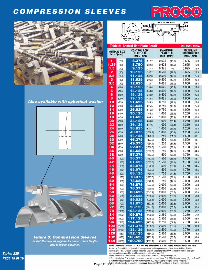
Also available with spherical washer
Metric Conversion: Nominal I.D.: in. x 25 = mm; Dimensions: in. x 25.4 = mm; Pressure: PSIG x .069 = BarNumber of Control Units is dependent upon pressure and temperature of system. Refer to Fluid SealingAssociation's - REJ Division Manual, Appendix C (Sixth Edition) for minimum number of control units (perpressure rating) required for a rubber expansion joint when specified.Values listed in this table are maximum values based on PROCO'S engineering data.1. Control rod plate O.D. installed dimension is based on a maximum O.D. PROCO would supply. (Figures 2 and 3.)2. Plate thickness is based on a maximum width PROCO would use to design a control rod plate.3. Control rod diameter is based on a maximum diameter PROCO would use to design a control rod.
COMPRESSION SLEEVES
Table 5: Control Unit Plate Detail See Notes Below
NOMINAL SIZEInch / (mm)
CONTROL ROD 1
PLATE O.D.Inch / (mm)
MAXIMUM 2
PLATE THKInch / (mm)
MAXIMUM 3
ROD DIAMETERInch / (mm)
1 (25) 8.375 (212.7) 0.625 (15.9) 0.625 (15.9)
1.25 (32) 8.750 (222.3) 0.625 (15.9) 0.625 (15.9)
1.5 (40) 9.125 (231.8) 0.375 (9.5) 0.625 (15.9)
2 (50) 10.125 (257.2) 0.500 (12.7) 0.625 (15.9)
2.5 (65) 11.125 (282.6) 0.500 (12.7) 1.000 (25.4)
3 (80) 11.625 (295.3) 0.500 (12.7) 1.000 (25.4)
3.5 (90) 12.625 (320.7) 0.625 (15.9) 1.000 (25.4)
4 (100) 13.125 (333.4) 0.625 (15.9) 1.000 (25.4)
5 (125) 14.125 (358.8) 0.500 (12.7) 1.000 (25.4)
6 (150) 15.125 (384.2) 0.500 (12.7) 1.000 (25.4)
8 (200) 19.125 (485.8) 0.625 (15.9) 1.000 (25.4)
10 (250) 21.625 (549.3) 0.750 (19.1) 1.000 (25.4)
12 (300) 24.625 (625.5) 0.750 (19.1) 1.000 (25.4)
14 (350) 26.625 (676.3) 0.750 (19.1) 1.000 (25.4)
16 (400) 30.125 (765.2) 1.000 (25.4) 1.250 (31.8)
18 (450) 31.625 (803.3) 1.000 (25.4) 1.250 (31.8)
20 (500) 34.125 (866.8) 1.000 (25.4) 1.250 (31.8)
22 (550) 36.125 (917.6) 1.000 (25.4) 1.250 (31.8)
24 (600) 38.625 (981.1) 1.000 (25.4) 1.250 (31.8)
26 (650) 40.875 (1038.2) 1.000 (25.4) 1.250 (31.8)
28 (700) 44.125 (1120.8) 1.250 (31.8) 1.500 (38.1)
30 (750) 46.375 (1177.9) 1.500 (38.1) 1.500 (38.1)
32 (800) 49.375 (1254.1) 1.250 (31.8) 1.500 (38.1)
34 (850) 52.375 (1330.3) 1.500 (38.1) 1.750 (44.5)
36 (900) 54.625 (1387.5) 1.750 (44.5) 1.750 (44.5)
38 (950) 57.375 (1457.3) 1.500 (38.1) 1.750 (44.5)
40 (1000) 58.375 (1482.7) 1.500 (38.1) 1.500 (38.1)
42 (1050) 61.625 (1565.3) 1.500 (38.1) 1.750 (44.5)
44 (1100) 63.875 (1622.4) 1.500 (38.1) 1.750 (44.5)
46 (1150) 65.875 (1673.2) 1.500 (38.1) 1.750 (44.5)
48 (1200) 68.125 (1730.4) 1.750 (44.5) 1.750 (44.5)
50 (1250) 70.375 (1787.5) 1.500 (38.1) 1.750 (44.5)
52 (1300) 73.625 (1870.1) 1.750 (44.5) 2.000 (50.8)
54 (1350) 75.875 (1927.2) 2.000 (50.8) 2.000 (50.8)
56 (1400) 78.375 (1990.7) 2.000 (50.8) 2.000 (50.8)
58 (1450) 80.625 (2047.9) 2.000 (50.8) 2.000 (50.8)
60 (1500) 82.625 (2098.7) 2.000 (50.8) 2.000 (50.8)
66 (1650) 89.625 (2276.5) 2.000 (50.8) 2.000 (50.8)
68 (1700) 91.875 (2333.6) 2.000 (50.8) 2.000 (50.8)
72 (1800) 96.125 (2441.6) 2.000 (50.8) 2.000 (50.8)
78 (2000) 103.125 (2619.4) 2.000 (50.8) 2.250 (57.2)
84 (2150) 109.875 (2790.8) 2.250 (57.2) 2.250 (57.2)
90 (2300) 117.125 (2975.0) 2.500 (63.5) 2.500 (63.5)
96 (2450) 124.625 (3165.9) 2.750 (69.9) 2.750 (69.9)
102 (2500) 131.375 (3336.5) 2.500 (63.5) 2.750 (69.9)
108 (2750) 138.125 (3508.4) 2.500 (63.5) 2.750 (69.9)
120 (3050) 152.125 (3864.0) 2.500 (63.5) 3.000 (76.2)
132 (3350) 166.625 (4232.2) 2.500 (63.5) 3.250 (82.6)
144 (3650) 180.750 (4591.1) 2.500 (63.5) 3.500 (88.9)
Series 230Page 13 of 16
Figure 3: Compression SleevesConsult the systems engineer for proper sleeve lengths
prior to system operation.
Page 111 of 119
Series 230Page 14 of 16
Series 230 Drilling Chart
Metric Conversion Formula: Nominal I.D.: in. x 25 = mm; Dimensions: in. x 25.4 = mm; Pressure: PSIG x .069 = BarNotes: 1. Control rod length is determined by OAL of rubber expansion joint, rated extension, retaining ring thickness, mating flange thickness and number of nuts. Consult PROCO for rod lengths.
2. Flange dimensions shown are in accordance with 125/150 pound standards: ANSI B16.1 AWWA C-207 Tables 1 and 2 Class D; AWWA C-207 Table 3 see Class E. Hole size shown is l/8" larger than AWWA standard.3. Plate thickness is based on a maximum width PROCO would use to design a control rod plate.
NOMINALPIPE SIZE
EXPANSIONJOINT I.D.Inch / (mm)
Table 6: Standard Drilling for PROCO Series 230/220 Rubber Expansion Joints Thickness of Materials for PROCO Series 230/220 Rubber Expansion Joints
FLANGE O.D.Inch / (mm)
BOLT CIRCLEInch / (mm)
NO.OF
HOLES
SIZEOF HOLES
125/150# Flange Dimensions 2 Material Thickness’ for Bolt Length Requirements
RETAINING RINGTHICKNESSInch / (mm)
RUBBER FLANGETHICKNESSInch / (mm)
ADJACENTMATING FLANGE
THICKNESS
MAX. CONTROL 3
ROD PLATETHICKNESSInch / (mm)
CUSTOMER
TO
SPECIFY
MATING
FLANGE
THICKNESS
Split Retaining Ring A - Retaining Ring ThicknessB - Rubber Flange ThicknessC - Adjacent Mating Flange ThicknessD - Control Unit Plate ThicknessE - Double Nut Thickness is determined by Control Rod DiameterF - Control Rod Bolt Length is determined by A through E + OAL 1
1 (25) 4.25 (107.95) 3.13 (79.50) 4 0.625 (15.9) 0.375 (9.53) 0.472 (11.99) 0.625 (15.9)
1.25 (32) 4.63 (117.60) 3.50 (88.90) 4 0.625 (15.9) 0.375 (9.53) 0.472 (11.99) 0.625 (15.9)
1.5 (40) 5.00 (127.00) 3.88 (98.55) 4 0.625 (15.9) 0.375 (9.53) 0.472 (11.99) 0.375 (9.5)
2 (50) 6.00 (152.40) 4.75 (120.65) 4 0.750 (19.1) 0.375 (9.53) 0.472 (11.99) 0.500 (12.7)
2.5 (65) 7.00 (177.80) 5.50 (139.70) 4 0.750 (19.1) 0.375 (9.53) 0.472 (11.99) 0.500 (12.7)
3 (80) 7.50 (190.50) 6.00 (152.40) 4 0.750 (19.1) 0.375 (9.53) 0.472 (11.99) 0.500 (12.7)
3.5 (90) 8.50 (215.90) 7.00 (177.80) 8 0.750 (19.1) 0.375 (9.53) 0.472 (11.99) 0.625 (15.9)
4 (100) 9.00 (228.60) 7.50 (190.50) 8 0.750 (19.1) 0.375 (9.53) 0.472 (11.99) 0.625 (15.9)
5 (125) 10.00 (254.00) 8.50 (215.90) 8 0.875 (22.2) 0.375 (9.53) 0.551 (14.00) 0.500 (12.7)
6 (150) 11.00 (279.40) 9.50 (241.30) 8 0.875 (22.2) 0.375 (9.53) 0.551 (14.00) 0.500 (12.7)
8 (200) 13.50 (342.90) 11.75 (298.45) 8 0.875 (22.2) 0.375 (9.53) 0.630 (16.00) 0.625 (15.9)
10 (250) 16.00 (406.40) 14.25 (361.95) 12 1.000 (25.4) 0.375 (9.53) 0.630 (16.00) 0.750 (19.1)
12 (300) 19.00 (482.60) 17.00 (431.80) 12 1.000 (25.4) 0.375 (9.53) 0.748 (19.00) 0.750 (19.1)
14 (350) 21.00 (533.40) 18.75 (476.25) 12 1.125 (28.6) 0.375 (9.53) 0.866 (22.00) 0.750 (19.1)
16 (400) 23.50 (596.90) 21.25 (539.75) 16 1.125 (28.6) 0.375 (9.53) 0.866 (22.00) 1.000 (25.4)
18 (450) 25.00 (635.00) 22.75 (577.85) 16 1.250 (31.8) 0.375 (9.53) 0.866 (22.00) 1.000 (25.4)
20 (500) 27.50 (698.50) 25.00 (635.00) 20 1.250 (31.8) 0.375 (9.53) 0.984 (25.00) 1.000 (25.4)
22 (550) 29.50 (749.30) 27.25 (692.15) 20 1.375 (34.9) 0.375 (9.53) 0.984 (25.00) 1.000 (25.4)
24 (600) 32.00 (812.80) 29.50 (749.30) 20 1.375 (34.9) 0.375 (9.53) 0.984 (25.00) 1.000 (25.4)
26 (650) 34.25 (869.95) 31.75 (806.45) 24 1.375 (34.9) 0.375 (9.53) 0.984 (25.00) 1.000 (25.4)
28 (700) 36.50 (927.10) 34.00 (863.60) 28 1.375 (34.9) 0.375 (9.53) 0.984 (25.00) 1.250 (31.8)
30 (750) 38.75 (984.25) 36.00 (914.40) 28 1.375 (34.9) 0.375 (9.53) 0.984 (25.00) 1.500 (38.1)
32 (800) 41.75 (1060.45) 38.50 (977.90) 28 1.625 (41.3) 0.375 (9.53) 0.984 (25.00) 1.250 (31.8)
34 (850) 43.75 (1111.25) 40.50 (1028.70) 32 1.625 (41.3) 0.375 (9.53) 0.984 (25.00) 1.500 (38.1)
36 (900) 46.00 (1168.40) 42.75 (1085.85) 32 1.625 (41.3) 0.375 (9.53) 0.984 (25.00) 1.750 (44.5)
38 (950) 48.75 (1238.25) 45.25 (1149.35) 32 1.625 (41.3) 0.375 (9.53) 0.984 (25.00) 1.500 (38.1)
40 (1000) 50.75 (1289.05) 47.25 (1200.15) 36 1.625 (41.3) 0.375 (9.53) 0.984 (25.00) 1.500 (38.1)
42 (1050) 53.00 (1346.20) 49.50 (1257.30) 36 1.625 (41.3) 0.375 (9.53) 1.181 (29.99) 1.500 (38.1)
44 (1100) 55.25 (1403.35) 51.75 (1314.45) 40 1.625 (41.3) 0.375 (9.53) 1.181 (29.99) 1.500 (38.1)
46 (1150) 57.25 (1454.15) 53.75 (1365.25) 40 1.625 (41.3) 0.375 (9.53) 1.181 (29.99) 1.500 (38.1)
48 (1200) 59.50 (1511.30) 56.00 (1422.40) 44 1.625 (41.3) 0.375 (9.53) 1.181 (29.99) 1.750 (44.5)
50 (1250) 61.75 (1568.45) 58.25 (1479.55) 44 1.875 (47.6) 0.375 (9.53) 1.181 (29.99) 1.500 (38.1)
52 (1300) 64.00 (1625.60) 60.50 (1536.70) 44 1.875 (47.6) 0.375 (9.53) 1.181 (29.99) 1.750 (44.5)
54 (1350) 66.25 (1682.75) 62.75 (1593.85) 44 2.000 (50.8) 0.375 (9.53) 1.181 (29.99) 2.000 (50.8)
56 (1400) 68.75 (1746.25) 65.00 (1651.00) 48 1.875 (47.6) 0.375 (9.53) 1.181 (29.99) 2.000 (50.8)
58 (1450) 71.00 (1803.40) 67.25 (1708.15) 48 1.875 (47.6) 0.375 (9.53) 1.181 (29.99) 2.000 (50.8)
60 (1500) 73.00 (1854.20) 69.25 (1758.95) 52 2.000 (50.8) 0.375 (9.53) 1.181 (29.99) 2.000 (50.8)
66 (1650) 80.00 (2032.00) 76.00 (1930.40) 52 2.000 (50.8) 0.375 (9.53) 1.181 (29.99) 2.000 (50.8)
68 (1700) 82.25 (2089.15) 78.25 (1987.55) 56 2.000 (50.8) 0.375 (9.53) 1.181 (29.99) 2.000 (50.8)
72 (1800) 86.50 (2197.10) 82.50 (2095.50) 60 2.000 (50.8) 0.375 (9.53) 1.181 (29.99) 2.000 (50.8)
78 (1950) 93.00 (2362.20) 89.00 (2260.60) 64 2.125 (53.0) 0.375 (9.53) 1.188 (30.18) 2.000 (50.8)
84 (2100) 99.75 (2533.65) 95.50 (2425.70) 64 2.250 (57.2) 0.375 (9.53) 1.188 (30.18) 2.250 (57.2)
90 (2250) 106.50 (2705.10) 102.00 (2590.80) 68 2.375 (60.3) 0.375 (9.53) 1.188 (30.18) 2.500 (63.5)
96 (2400) 113.25 (2876.55) 108.50 (2755.90) 68 2.500 (63.5) 0.375 (9.53) 1.188 (30.18) 2.750 (69.9)
102 (2550) 120.00 (3048.00) 114.50 (2908.30) 72 2.625 (66.7) 0.375 (9.53) 1.188 (30.18) 2.500 (63.5)
108 (2700) 126.75 (3219.45) 120.75 (3067.05) 72 2.625 (66.7) 0.375 (9.53) 1.188 (30.18) 2.500 (63.5)
120 (3000) 140.25 (3562.35) 132.75 (3371.85) 76 2.875 (73.0) 0.375 (9.53) 1.188 (30.18) 2.500 (63.5)
132 (3300) 153.75 (3905.25) 145.75 (3705.05) 80 3.125 (79.4) 0.375 (9.53) 1.188 (30.18) 2.500 (63.5)
144 (3600) 167.25 (4248.15) 158.25 (4019.55) 84 3.375 (85.7) 0.375 (9.53) 1.188 (30.18) 2.500 (63.5)
Page 112 of 119

Tab 5 General Brochures
Page 113 of 119

Here is your conveying solution:Product group N.
Page 114 of 119

Coupling rod for power transmission. Improveddesign, special designs optional available.
N – Standard pumps
The two ranges of pumps within the product group N form
the basis of all seepex progressive cavity pumps. They are
available with various rotor/stator geometries (conventional,
6L, and Tricam) and can be applied in virtually all industrial
sectors – for conveying thin to viscous media with or without
solids.
Joint connectionconsisting of just 5 components.Power transmission through wearresistant, hardened and replaceablejoint parts: easily repaired.
Dry running protection TSE, thermoelectronicprevents the stator from being damaged bydry running, optional available.
Statorthe seal on both ends is moulded as an integral part of the elastomericstator; corrosion of the stator tubeis never a problem because the pum-ped liquid never comes into contactwith the metal tube or the bondingadhesive. Available with optionaladjustable stator retensioning device.
Rotorwear resistant and corrosion-proofmaterials, with additional surface treatment.
Tie bolts/screwscorrosion proof, optional available instainless steel design.
Universal joint sleeve protectionmade of stainless steel, protects the universal joint sleeve against mecha-nical damage from large/angular solids,optional available.
Inspection portson both sides, optional.
2
Pressure branch connection for pressure/vacuum gauge.Flange connections in DIN or ANSI.
Page 115 of 119
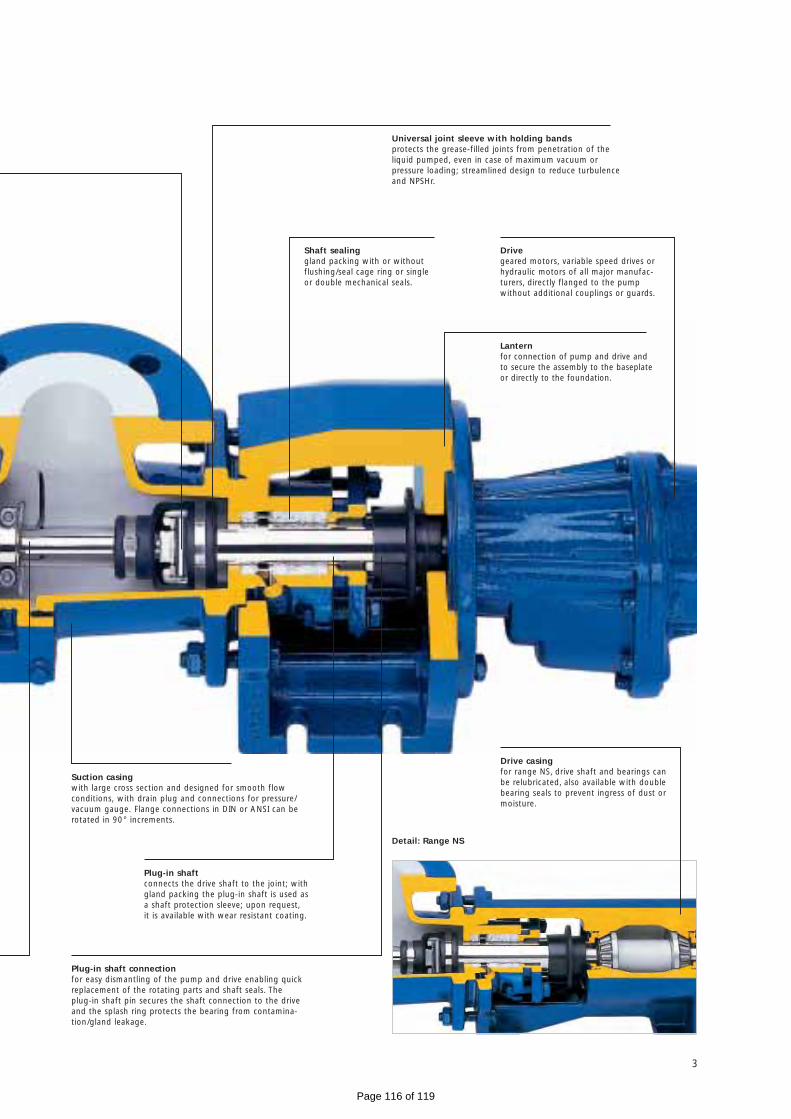
Suction casing with large cross section and designed for smooth flow conditions, with drain plug and connections for pressure/vacuum gauge. Flange connections in DIN or ANSI can berotated in 90° increments.
Universal joint sleeve with holding bandsprotects the grease-filled joints from penetration of theliquid pumped, even in case of maximum vacuum or pressure loading; streamlined design to reduce turbulenceand NPSHr.
Lanternfor connection of pump and drive andto secure the assembly to the baseplateor directly to the foundation.
Shaft sealinggland packing with or withoutflushing/seal cage ring or singleor double mechanical seals.
Drivegeared motors, variable speed drives orhydraulic motors of all major manufac-turers, directly flanged to the pumpwithout additional couplings or guards.
Plug-in shaft connectionfor easy dismantling of the pump and drive enabling quickreplacement of the rotating parts and shaft seals. Theplug-in shaft pin secures the shaft connection to the driveand the splash ring protects the bearing from contamina-tion/gland leakage.
Plug-in shaftconnects the drive shaft to the joint; withgland packing the plug-in shaft is used asa shaft protection sleeve; upon request,it is available with wear resistant coating.
Drive casingfor range NS, drive shaft and bearings can be relubricated, also available with doublebearing seals to prevent ingress of dust ormoisture.
3
Detail: Range NS
Page 116 of 119

Because they are used in applications such as agriculture,
ceramics, chemical and biochemical industry, construction,
dyeing and varnishing, electroplating, environment techno-
logy, fish industry, food and beverage industry, mining, non-
metallic minerals, oil production and offshore technology,
petrochemicals, pharmaceutical and cosmetics industry, pulp
and paper industry, shipbuilding, sugar industry, supply and
waste disposal industry, textile industry, vehicle construction
and equipment and wood processing industry.
Features
• Minimal pulsation, controlled flow, so that no pulsation
dampers or compensators are required
• Self-priming, even with air or gas liquid mixtures of up
to 9 m (29.5’) of water
• Installation versatility as pumps can be mounted either
horizontally or vertically and the suction casing can be
rotated
• Products with solids can be conveyed gently without
damage
• Direction of rotation and fluid flow are reversible
> Conveying capacity: 30 l/h–500 m3/h (0.13 GPM–2200 GPM),
Pressure: up to 48 bar (720 psi)
Why standard pumps?
4
Page 117 of 119

5
The drive of BN range pumps is directly flange-mounted to
the pump. This means that a separate pump bearing is not
necessary and the pump is more compact and less expensive.
The plug-in shaft connection between drive and the rotating
unit simplifies the replacement of rotating wearing parts
and the shaft sealing, thereby making the BN range very
service-friendly.
In pumps of the NS range the drives are not directly flange-
mounted in favour of a universal configuration of the drives.
They have a drive casing and a free shaft end, an elastic
coupling or a V-belt and a service-friendly plug-in connection.
This simplifies the replacement of the rotating wearing parts
and the shaft sealing without dismantling the bearing.
Overview of ranges
Range BN
Range NS/N
Page 118 of 119

And what can we get flowing for you? Your nearest contact:
Or visit www.seepex.com N 8
.06
E
Page 119 of 119