Embed Size (px)
Citation preview
EN
Co
py
rig
ht
© G
rau
pn
er/
SJ
Gm
bH
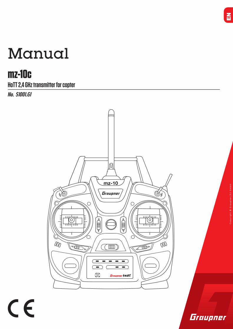
No. S1001.G1
HoTT 2,4 GHz transmitter for coptermz-10c
Manual
mz-10
EN

2 / 32 S1001.G1_sh_V1
3 / 32S1001.G1_sh_V1
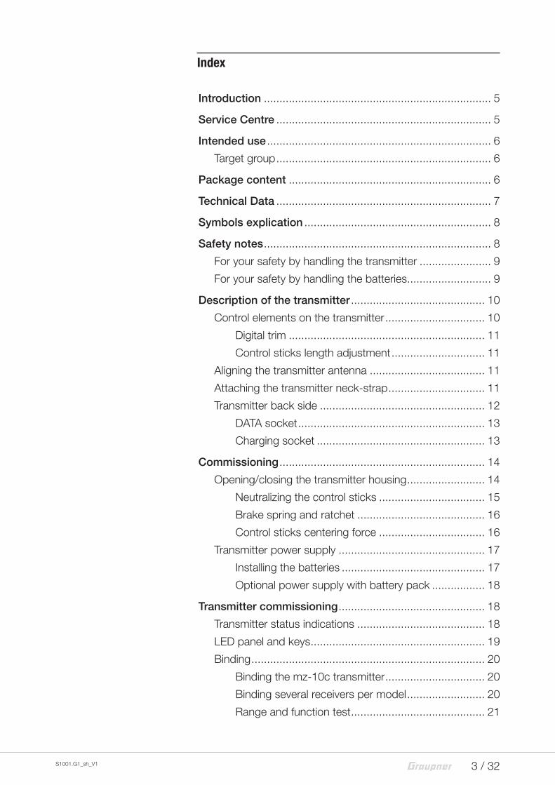
Index
Introduction ......................................................................... 5
Service Centre ..................................................................... 5
Intended use ........................................................................ 6
Target group ..................................................................... 6
Package content ................................................................. 6
Technical Data ..................................................................... 7
Symbols explication ............................................................ 8
Safety notes ......................................................................... 8
For your safety by handling the transmitter ....................... 9
For your safety by handling the batteries ........................... 9
Description of the transmitter ........................................... 10
Control elements on the transmitter ................................ 10
Digital trim ............................................................... 11
Control sticks length adjustment .............................. 11
Aligning the transmitter antenna ..................................... 11
Attaching the transmitter neck-strap ............................... 11
Transmitter back side ..................................................... 12
DATA socket ............................................................ 13
Charging socket ...................................................... 13
Commissioning .................................................................. 14
Opening/closing the transmitter housing ......................... 14
Neutralizing the control sticks .................................. 15
Brake spring and ratchet ......................................... 16
Control sticks centering force .................................. 16
Transmitter power supply ............................................... 17
Installing the batteries .............................................. 17
Optional power supply with battery pack ................. 18
Transmitter commissioning ............................................... 18
Transmitter status indications ......................................... 18
LED panel and keys ........................................................ 19
Binding ........................................................................... 20
Binding the mz-10c transmitter ................................ 20
Binding several receivers per model ......................... 20
Range and function test ........................................... 21
4 / 32 S1001.G1_sh_V1
Range warning ........................................................ 22
Operation and settings ...................................................... 23
Transmitter programming ................................................ 23
Country setting ........................................................ 23
Control mode .......................................................... 24
Fail Safe ................................................................... 25
Switch functions ...................................................... 28
Firmware update ............................................................... 29
Transmitter software update ........................................... 30
Declaration of conformity ................................................. 30
Disposal ............................................................................. 31
Care and maintenance ...................................................... 31
Warranty certificate ........................................................... 31
5 / 32S1001.G1_sh_V1
IntroductionThank you very much for purchasing the Graupner mz-10c HoTT transmitter.
Read this manual carefully to achieve the best results with your transmitter and first of all to safely control your models. If you experience any trouble during operation, take the instructions to help or ask your dealer or Graupner Service Centre.
Due to technical changes, the information may be changed in this manual without prior notice. Be always updated by checking periodically on our website, www.graupner.de to be always upto-date with the products and firmwares.
This product complies with national and European legal require-ments.
To maintain this condition and to ensure safe operation, you must read and follow this user manual and all the safety notes before using the product!
NoteThis manual is part of that product. It contains important information concerning operation and handling. Keep these instructions for future reference and give it to third person in case you gave the product.
Service CentreGraupner Central Service
Graupner/SJ GmbHHenriettenstraße 96D-73230 Kirchheim / Teck
Servicehotline
(+49) (0)7021/722-130Monday - Thursday9:15 am - 4:00 pmFriday9:15 am - 1:00 pm
Graupner in Internet For the service centers outside Germany please refer to our web site www.graupner.de.
Graupner USA
3941 Park Dr Suite 20-571
El Dorado Hills, CA. 95762
US
Phone: 855-572-4746
Email: [email protected]
�
6 / 32 S1001.G1_sh_V1
Intended useThis remote-control system may only be used for the purpose specified by the manufacturer for operation of remote control models without passengers. Any other type of use is impermis-sible and may damage the system and cause significant pro-perty damage and/or personal injury. No warranty or liability is therefore offered for any improper use not covered by these pro-visions.
Read through this entire manual before you attempt to install or use the transmitter.
Graupner/SJ constantly works on the development of all pro-ducts; we reserve the right to change the item, its technology and equipment.
Target groupThe product is not a toy. It is not suitable for children under 14 years. The operation of the mz-10c HoTT transmitter must be performed by experienced modelers. If you do not have suffi-cient knowledge about dealing with radio-controlled models, please contact an experienced modeler or a model club.
Package content � Transmitter mz-10c HoTT
� 4 batteries AA type (not rechargeable)
� Battery box
� Programming connector
� Receiver (optional)
� Transmitter manual
� Receiver manual (optional)
7 / 32S1001.G1_sh_V1
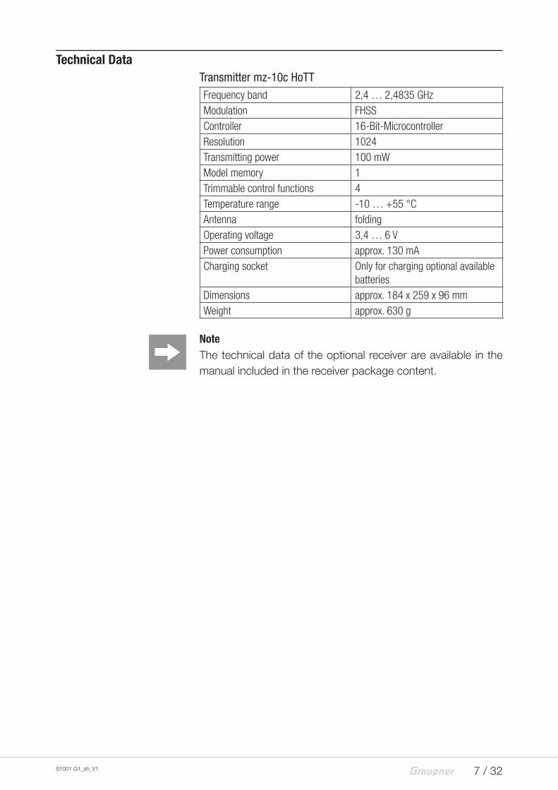
Technical DataTransmitter mz-10c HoTTFrequency band 2,4 … 2,4835 GHzModulation FHSSController 16-Bit-MicrocontrollerResolution 1024Transmitting power 100 mWModel memory 1Trimmable control functions 4Temperature range -10 … +55 °CAntenna foldingOperating voltage 3,4 … 6 VPower consumption approx. 130 mACharging socket Only for charging optional available
batteriesDimensions approx. 184 x 259 x 96 mmWeight approx. 630 g
NoteThe technical data of the optional receiver are available in the manual included in the receiver package content.
8 / 32 S1001.G1_sh_V1
Symbols explication
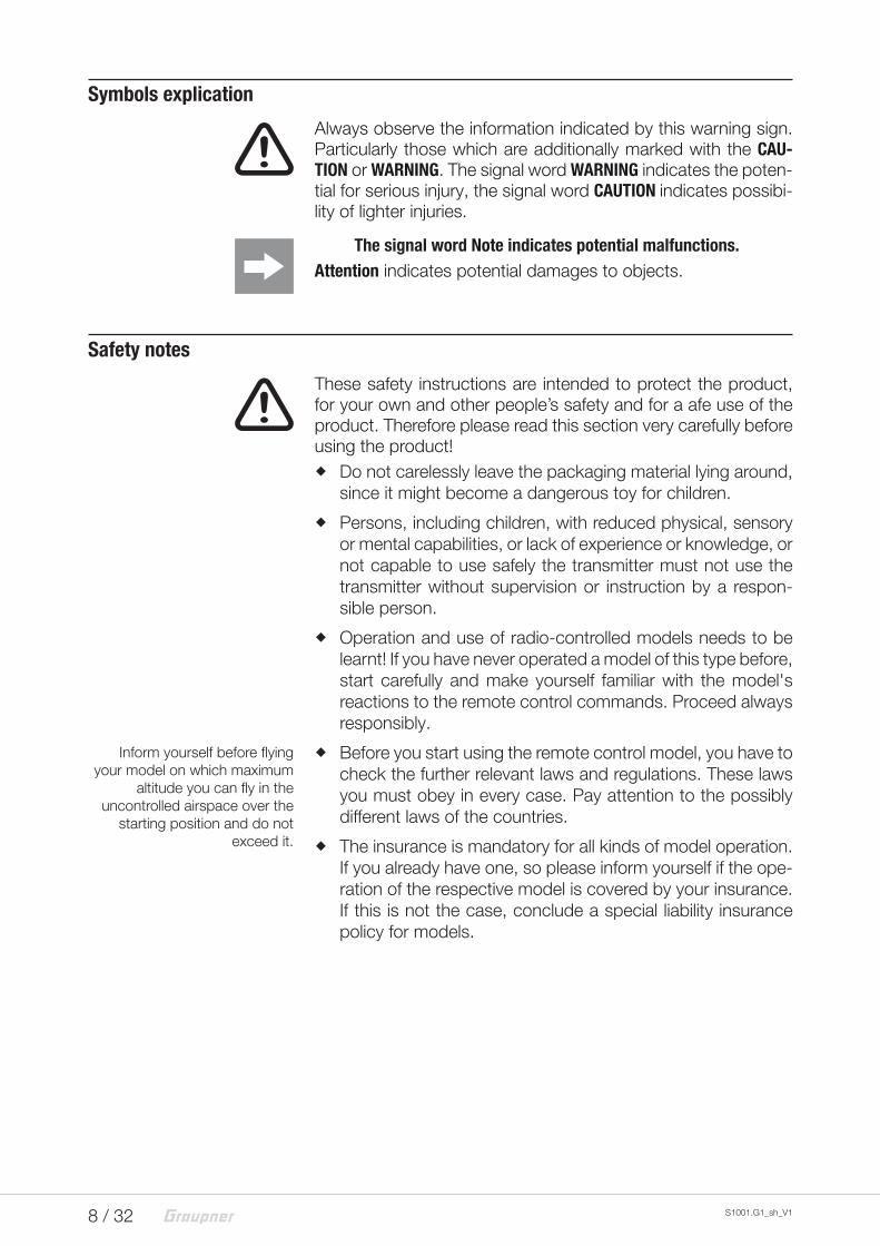
!Always observe the information indicated by this warning sign. Particularly those which are additionally marked with the CAU-TION or WARNING. The signal word WARNING indicates the poten-tial for serious injury, the signal word CAUTION indicates possibi-lity of lighter injuries.
The signal word Note indicates potential malfunctions.Attention indicates potential damages to objects.
Safety notes
!These safety instructions are intended to protect the product, for your own and other people’s safety and for a afe use of the product. Therefore please read this section very carefully before using the product!
� Do not carelessly leave the packaging material lying around, since it might become a dangerous toy for children.
� Persons, including children, with reduced physical, sensory or mental capabilities, or lack of experience or knowledge, or not capable to use safely the transmitter must not use the transmitter without supervision or instruction by a respon-sible person.
� Operation and use of radio-controlled models needs to be learnt! If you have never operated a model of this type before, start carefully and make yourself familiar with the model's reactions to the remote control commands. Proceed always responsibly.
� Before you start using the remote control model, you have to check the further relevant laws and regulations. These laws you must obey in every case. Pay attention to the possibly different laws of the countries.
� The insurance is mandatory for all kinds of model operation. If you already have one, so please inform yourself if the ope-ration of the respective model is covered by your insurance. If this is not the case, conclude a special liability insurance policy for models.
Inform yourself before flying your model on which maximum
altitude you can fly in the uncontrolled airspace over the
starting position and do not exceed it.
9 / 32S1001.G1_sh_V1
� Protect all equipment from dust, dirt, moisture. All equipment must be protected from vibration as well as excessive heat or cold. The models may only be operated remotely in nor-mal outside temperatures such as from -10°C to +55°C.
For your safety by handling the transmitter
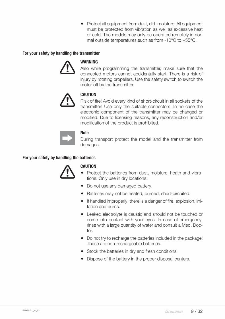
!WARNING Also while programming the transmitter, make sure that the connected motors cannot accidentally start. There is a risk of injury by rotating propellers. Use the safety switch to switch the motor off by the transmitter.
!CAUTION Risk of fire! Avoid every kind of short-circuit in all sockets of the transmitter! Use only the suitable connectors. In no case the electronic component of the transmitter may be changed or modified. Due to licensing reasons, any reconstruction and/or modification of the product is prohibited.
NoteDuring transport protect the model and the transmitter from damages.
For your safety by handling the batteries
!CAUTION
� Protect the batteries from dust, moisture, heath and vibra-tions. Only use in dry locations.
� Do not use any damaged battery.
� Batteries may not be heated, burned, short-circuited.
� If handled improperly, there is a danger of fire, explosion, irri-tation and burns.
� Leaked electrolyte is caustic and should not be touched or come into contact with your eyes. In case of emergency, rinse with a large quantity of water and consult a Med. Doc-tor.
� Do not try to recharge the batteries included in the package! Those are non-rechargeable batteries.
� Stock the batteries in dry and fresh conditions.
� Dispose of the battery in the proper disposal centers.
10 / 32 S1001.G1_sh_V1
Description of the transmitter
Control elements on the transmitter
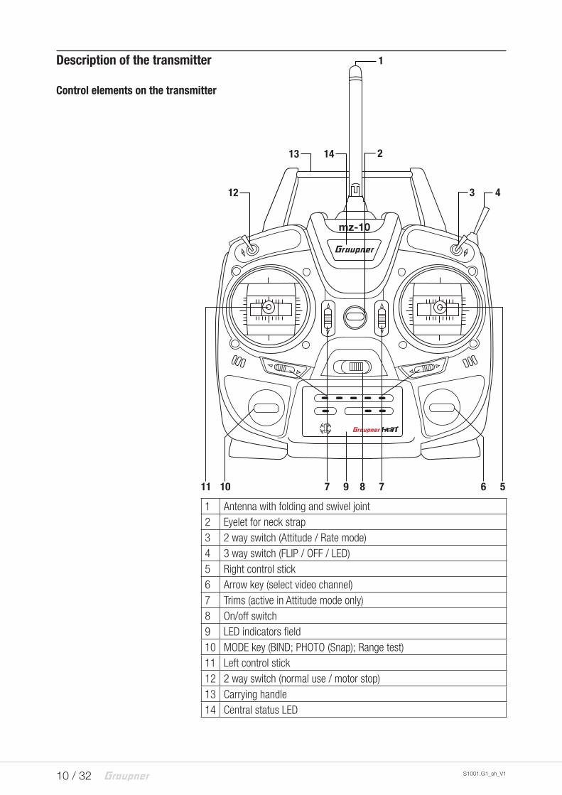
1 Antenna with folding and swivel joint2 Eyelet for neck strap3 2 way switch (Attitude / Rate mode)4 3 way switch (FLIP / OFF / LED)5 Right control stick6 Arrow key (select video channel)7 Trims (active in Attitude mode only)8 On/off switch9 LED indicators field10 MODE key (BIND; PHOTO (Snap); Range test)11 Left control stick12 2 way switch (normal use / motor stop)13 Carrying handle14 Central status LED
mz-10
7 5
1
2
3 4
68971011
12
13 14
11 / 32S1001.G1_sh_V1
Digital trim
Digital trim with an acoustic feedbackThe two control sticks have digital trimming.
NoteThe digital trim is active only in the previously mentioned position of the Attitude / Rate mode switch (3) on the upper right part of the transmitter.
Briefly touch the trimming switch to move the neutral position of the control stick by a specific value with each click. If it is held, the trimming moves in the corresponding direction with increa-sing speed.
The adjustment is made "audible" by tones of varying levels. It is therefore easy to find the middle position during flight. If you go past the middle position, a brief pause is inserted.
The current trimming values are saved.
Control sticks length adjustment
Length of both control stick can be adjusted. Hold down the bottom half of the knurled grip, and loosen the screwed connec-tion by turning the top part:
You can now lengthen or shorten the control stick by screwing it up or down. Then clamp the top and bottom part of the grip by rotating them against each other.
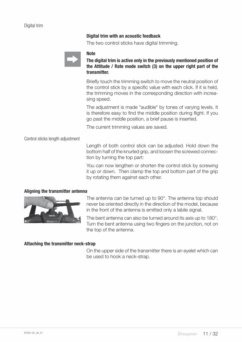
Aligning the transmitter antennaThe antenna can be turned up to 90°. The antenna top should never be oriented directly in the direction of the model, because in the front of the antenna is emitted only a labile signal.
The bent antenna can also be turned around its axis up to 180°. Turn the bent antenna using two fingers on the junction, not on the top of the antenna.
Attaching the transmitter neck-strapOn the upper side of the transmitter there is an eyelet which can be used to hook a neck-strap.
12 / 32 S1001.G1_sh_V1
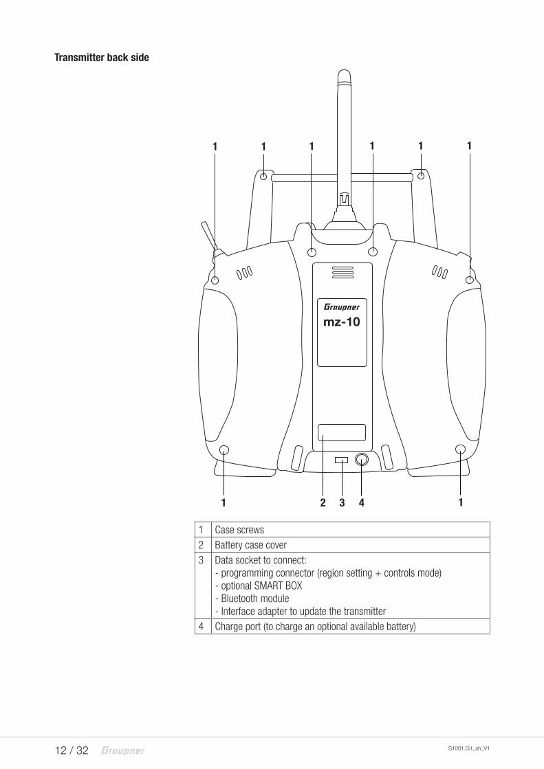
Transmitter back side
mz-10
1 11 1 11
1 2 3 4 1
1 Case screws2 Battery case cover3 Data socket to connect:
- programming connector (region setting + controls mode)- optional SMART BOX- Bluetooth module- Interface adapter to update the transmitter
4 Charge port (to charge an optional available battery)
13 / 32S1001.G1_sh_V1
DATA socket
Suitable to connect ...
1. … the optionally available SMART-BOX to display telemetry data and for setting the receiver.
2. … the optionally available USB adapter to update the trans-mitter through a PC.
3. ... the optional available Bluetooth module for the transmis-sion of telemetry data to a compatible smartphone or tablet.
Polarity of the socket "DATA / S + -“:
S = signal line (orange)
+ = Plus line (red)
- = Minus line (brown or black)
You can find more information about the listed accessories on www.graupner.de.
Charging socket
This port has to be used only for charging optional available rechargeable batteries.
!WARNING Never charge dry batteries through this port. An acute explosion hazard exists.
14 / 32 S1001.G1_sh_V1
Commissioning
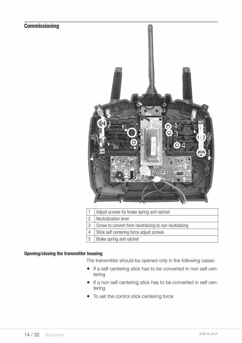
1 Adjust screws for brake spring and ratchet2 Neutralization lever3 Screw to convert from neutralizing to non neutralizing4 Stick self centering force adjust screws5 Brake spring and ratchet
Opening/closing the transmitter housingThe transmitter should be opened only in the following cases:
� If a self centering stick has to be converted in non self cen-tering
� If a non self centering stick has to be converted in self cen-tering
� To set the control stick centering force
1
1
23
34
45
15 / 32S1001.G1_sh_V1
! CAUTIONNever switch the transmitter on while the housing is open!
Open step by step:Before opening the housing switch the transmitter off.
Open the battery case.
Remove the battery box lifting it from one side and gently release it from the velcro tape.
Unplug the connector.
Unscrew the eight screws with a crossscrewdriver.
Hold both housing halves with both hands and let the screws fall on a proper surface turning the transmitter upside-down.
Rotate the lower half carefully and fold it to the bottom.
NoteCables connect the lower half of the housing with the upper part electronic components. This connection must not be damaged! Do not touch the electronic boards.
Closing step by step:Check if the upper and the lower part of the transmitter housing are correctly coupled and the tiny cables are properly placed.
Screw the housing screws in their shrouds.
Reconnect the battery box.
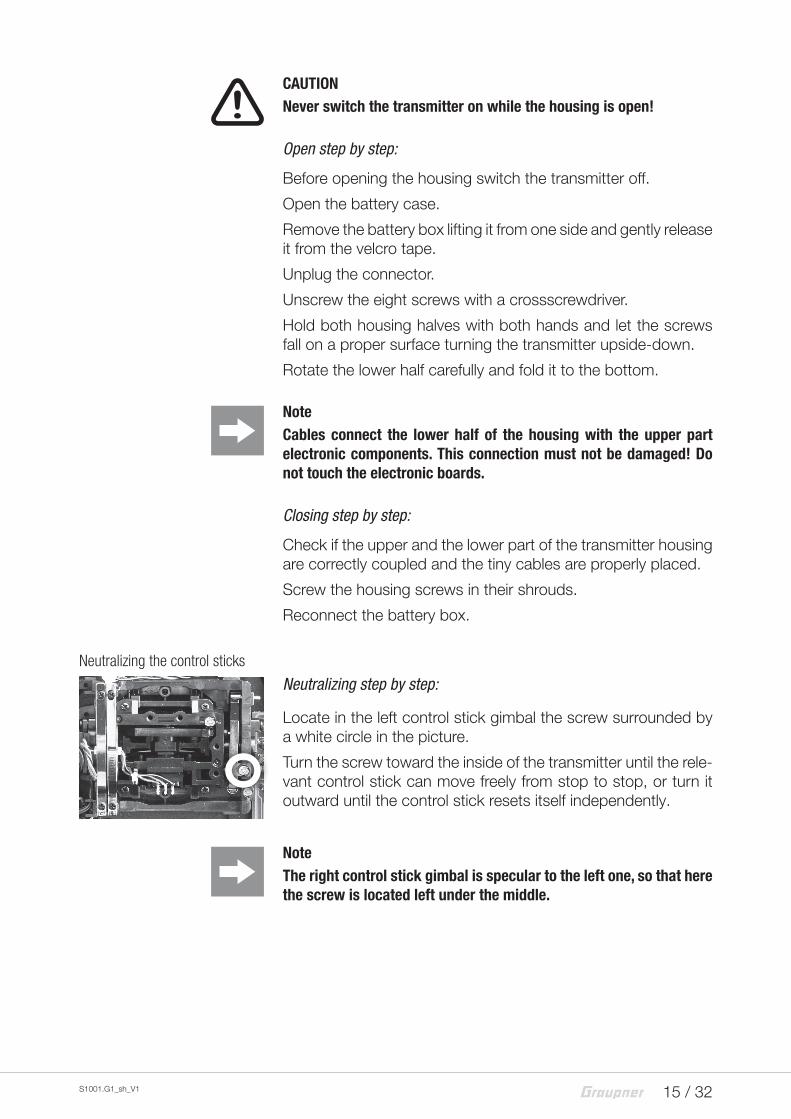
Neutralizing the control sticks
Neutralizing step by step:
Locate in the left control stick gimbal the screw surrounded by a white circle in the picture.
Turn the screw toward the inside of the transmitter until the rele-vant control stick can move freely from stop to stop, or turn it outward until the control stick resets itself independently.
NoteThe right control stick gimbal is specular to the left one, so that here the screw is located left under the middle.
16 / 32 S1001.G1_sh_V1
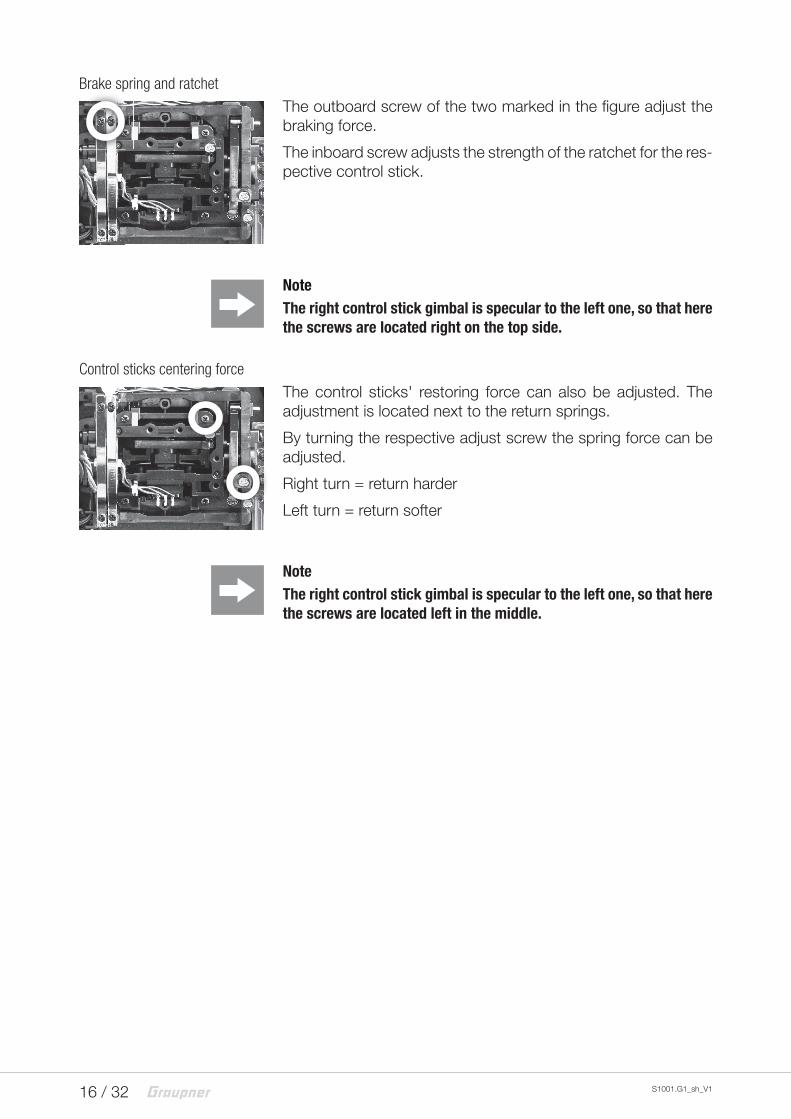
Brake spring and ratchet
The outboard screw of the two marked in the figure adjust the braking force.
The inboard screw adjusts the strength of the ratchet for the res-pective control stick.
NoteThe right control stick gimbal is specular to the left one, so that here the screws are located right on the top side.
Control sticks centering force
The control sticks' restoring force can also be adjusted. The adjustment is located next to the return springs.
By turning the respective adjust screw the spring force can be adjusted.
Right turn = return harder
Left turn = return softer
NoteThe right control stick gimbal is specular to the left one, so that here the screws are located left in the middle.
17 / 32S1001.G1_sh_V1
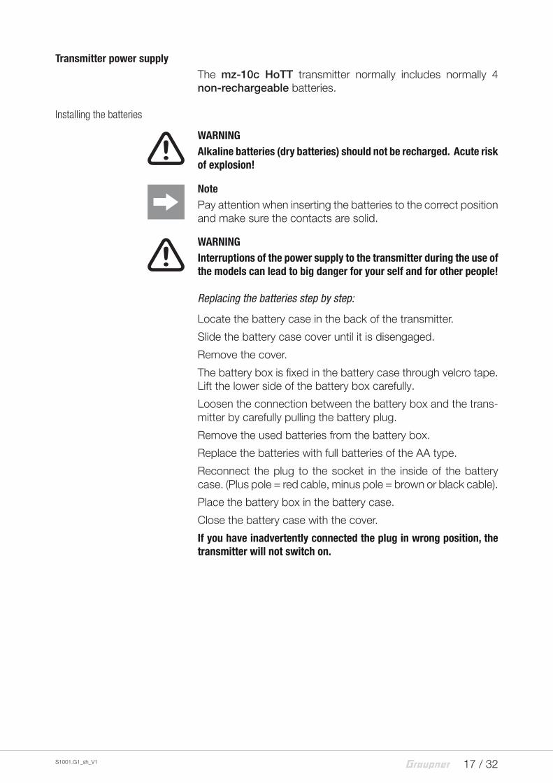
Transmitter power supplyThe mz-10c HoTT transmitter normally includes normally 4 non-rechargeable batteries.
Installing the batteries
! WARNINGAlkaline batteries (dry batteries) should not be recharged. Acute risk of explosion!
NotePay attention when inserting the batteries to the correct position and make sure the contacts are solid.
! WARNINGInterruptions of the power supply to the transmitter during the use of the models can lead to big danger for your self and for other people!
Replacing the batteries step by step:Locate the battery case in the back of the transmitter.
Slide the battery case cover until it is disengaged.
Remove the cover.
The battery box is fixed in the battery case through velcro tape. Lift the lower side of the battery box carefully.
Loosen the connection between the battery box and the trans-mitter by carefully pulling the battery plug.
Remove the used batteries from the battery box.
Replace the batteries with full batteries of the AA type.
Reconnect the plug to the socket in the inside of the battery case. (Plus pole = red cable, minus pole = brown or black cable).
Place the battery box in the battery case.
Close the battery case with the cover.
If you have inadvertently connected the plug in wrong position, the transmitter will not switch on.
18 / 32 S1001.G1_sh_V1
Optional power supply with battery pack
Instead of dry batteries you can use rechargeable NiMH batte-ries. The charging port on the back side of the transmitter is only suitable to charge rechargeable NiMH batteries.
! WARNINGFollow the safety instructions included with the batteries!
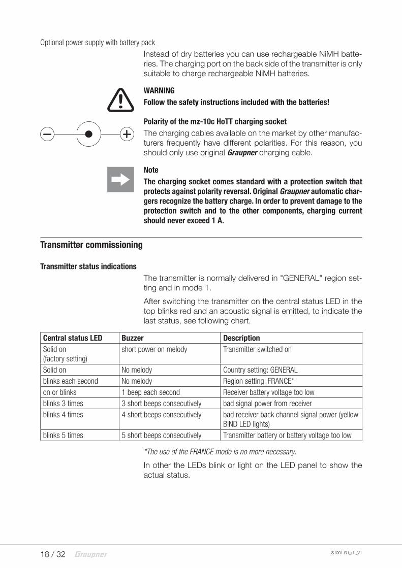
Polarity of the mz-10c HoTT charging socketThe charging cables available on the market by other manufac-turers frequently have different polarities. For this reason, you should only use original Graupner charging cable.
NoteThe charging socket comes standard with a protection switch that protects against polarity reversal. Original Graupner automatic char-gers recognize the battery charge. In order to prevent damage to the protection switch and to the other components, charging current should never exceed 1 A.
Transmitter commissioning
Transmitter status indicationsThe transmitter is normally delivered in "GENERAL" region set-ting and in mode 1.
After switching the transmitter on the central status LED in the top blinks red and an acoustic signal is emitted, to indicate the last status, see following chart.
Central status LED Buzzer DescriptionSolid on(factory setting)
short power on melody Transmitter switched on
Solid on No melody Country setting: GENERALblinks each second No melody Region setting: FRANCE*on or blinks 1 beep each second Receiver battery voltage too lowblinks 3 times 3 short beeps consecutively bad signal power from receiverblinks 4 times 4 short beeps consecutively bad receiver back channel signal power (yellow
BIND LED lights)blinks 5 times 5 short beeps consecutively Transmitter battery or battery voltage too low
*The use of the FRANCE mode is no more necessary.
In other the LEDs blink or light on the LED panel to show the actual status.
19 / 32S1001.G1_sh_V1
LED panel and keys
Cut-o� Rate CH6 CH7 CH8
BIND -100% +100%CH9
1 2 3 4 5 6 7
9 108
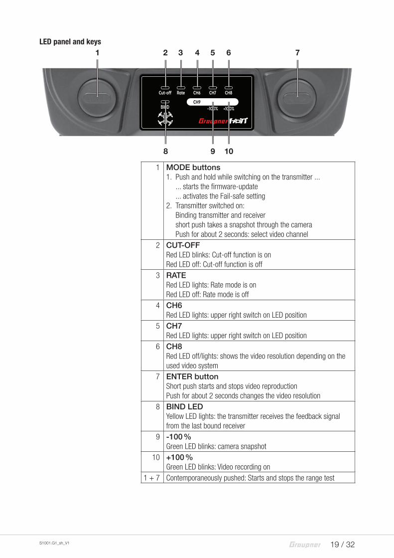
1 MODE buttons1. Push and hold while switching on the transmitter ...
... starts the firmware-update
... activates the Fail-safe setting2. Transmitter switched on:
Binding transmitter and receivershort push takes a snapshot through the cameraPush for about 2 seconds: select video channel
2 CUT-OFFRed LED blinks: Cut-off function is onRed LED off: Cut-off function is off
3 RATERed LED lights: Rate mode is onRed LED off: Rate mode is off
4 CH6Red LED lights: upper right switch on LED position
5 CH7Red LED lights: upper right switch on LED position
6 CH8Red LED off/lights: shows the video resolution depending on the used video system
7 ENTER buttonShort push starts and stops video reproductionPush for about 2 seconds changes the video resolution
8 BIND LEDYellow LED lights: the transmitter receives the feedback signal from the last bound receiver
9 -100 %Green LED blinks: camera snapshot
10 +100 %Green LED blinks: Video recording on
1 + 7 Contemporaneously pushed: Starts and stops the range test
20 / 32 S1001.G1_sh_V1
Binding
Binding the mz-10c transmitter
When binding, make sure that the transmitter antenna is always far enough away (1 to 2 meters) from the receiver antenna.
Binding step by step:1. Switch the transmitter on and connect the power supply to
the receiver. Accordingly to the manual of your HoTT recei-ver, a LED indicates that there is no contact with a transmit-ter.
2. Activate the binding process in your receiver, as described in its manual.
3. Push the MODE button on the already switched on the trans-mitter. As soon as the BIND LED on the transmitter lights yel-low and the LED on your receiver indicates a correct binding accordingly with the manual, transmitter and receiver are correctly bound.
If instead the LED on the receiver indicates wrong contact and the BIND LED on the receiver is still off, the binding pro-cess went wrong. Change the positions of the associated antennas and try the entire procedure again.
4. After binding transmitter and receiver perform a range test.
Binding several receivers per model
If necessary it is also possible to bind more than one receiver to a particular model. First bind each receiver individually as descri-bed earlier.
In next use the transmitter will however set a telemetry connec-tion only with the last bound receiver. Sensors eventually instal-led in the model have to be connected to this receiver, because the transmitter will indicate only the values coming from the back chaneel of the last bound recever. All other receiver work in par-allel to the last receiver bound to the transmitter, completely independently from this in the so called "Slave- Mode“!
21 / 32S1001.G1_sh_V1
Range and function test
When the range test starts, through contemporaneously pus-hing the left MODE and the right ENTER keys, the transmitter output power decreases significantly, then you can perform a function test in a distance not higher than 100 m. After the 90 second range test, the transmitter switches back to full output, and the signal tone stops. Alternatively you can always interrupt the range test by pushing for approximately 1 - 2 seconds the MODE and ENTER keys.
It is useful to have an assistant who helps you.
NoteIn case of use of more than 1 receiver per model note: the range test works only with the last bound receiver. Only with it there is a feed-back channel for the telemetry connection.
Range test step by step:1. Install the already bound receiver in the model.
2. Place the model on a flat surface (concrete, mowed lawn or ground) so that the receiver antennas are at least 15 cm above the ground. It may therefore be necessary to place a support underneath the model during the test.
3. Secure it properly and safely so that it cannot move if you start the motors during the range test.
4. Switch the transmitter on and wait until the receiver/s indi-cate/s according to the manual a correct function connec-tion. The model functions should react to the control movements.
5. Hold the transmitter at hip level at a slight distance from your body. Do not point the antenna directly to the model; rotate and/or bend the antenna so that is it is approximately at a right angle to the model.
6. Push contemporaneously the left MODE and the right ENTER keys until the transmitter starts beeping quickly. Release the MODE button.
7. During this time lapse, walk away from the model and move the sticks controlling the reactions of the model functions. In this phase do not use too much throttle so that the model does not get high. If you detect an interruption in the link wit-hin a range of about 50 m at any time, attempt to reproduce it.
8. Move further away from the model until it does not respond perfectly any more.
9. At this location, wait for the remainder of the test period with the still operable model or push simultaneously the left MODE and the right ENTER keys for about 1 - 2 seconds to stop
22 / 32 S1001.G1_sh_V1
the test. As soon as the range test has finished, the model should react exactly to the controls movements. If this is not 100 % the case, do not use the system and contact your Service at Graupner/SJ GmbH.
10. Perform a range test before each flight, and simulate all fuc-tions that could occur during the flight. In order to guarantee a safe model operation, the range must always be at least 50 m on the ground.
! CAUTIONNever start a range test on the transmitter during normal model ope-ration!
Range warning
As soon as the receiver signal on the feedback channel is low, the range warning will be active. Since the transmitter's output is significantly higher than the feedback channel of the receiver, the model can always be operated safely. For safety you should however reduce the model distance, until the signal quits again.
If the acoustic warning singal does not quit inspate the reduced distance, the use of the model should be interrupted immedia-tely and the transmitter should be checked. Eventually the trans-mitter's under-voltage or receiver's temperature warning are active. Then the battery should be charged or the receiver tem-perature should be checked.
NoteIn case the transmitter cannot set a connection to a proper back channel or during the use an existing connection is interrupted, the transmitter mz-10c BIND LED turns off and the buzzer indicates it with a 4 times beep signal (back channel missing), after that with a 3 times beep following until the transmission interference persists. Contemporaneously the status LED blinks 3 times.
23 / 32S1001.G1_sh_V1
Operation and settings
Transmitter programming
!CAUTIONSwitch the receiver off in your copter so that, during the program-ming process of the options described in the following paragraphs, the motors do not start accidentally.
NotesWithin an activation of the described below rotation procedure for setting the desired locale or control arrangement, however, only one option can always be activated. Afterwards the rotation procedure again must be recalled.
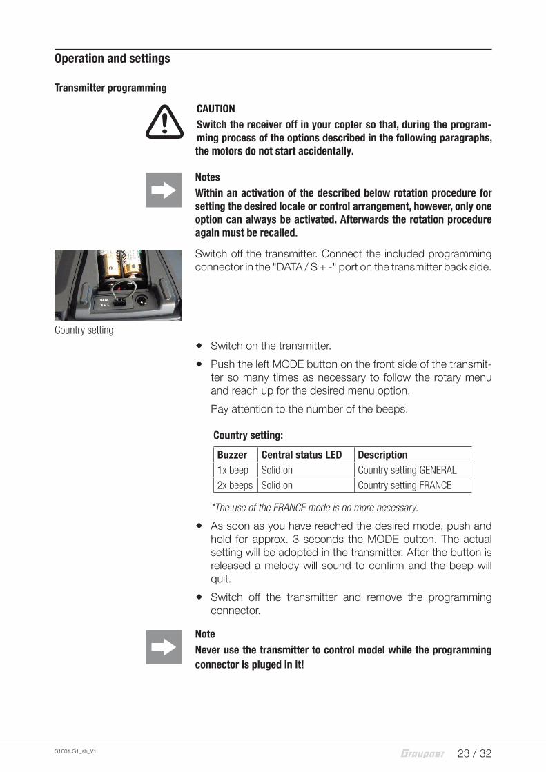
Switch off the transmitter. Connect the included programming connector in the "DATA / S + -" port on the transmitter back side.
Country setting
� Switch on the transmitter.
� Push the left MODE button on the front side of the transmit-ter so many times as necessary to follow the rotary menu and reach up for the desired menu option.
Pay attention to the number of the beeps.
Country setting:
Buzzer Central status LED Description1x beep Solid on Country setting GENERAL2x beeps Solid on Country setting FRANCE
*The use of the FRANCE mode is no more necessary.
� As soon as you have reached the desired mode, push and hold for approx. 3 seconds the MODE button. The actual setting will be adopted in the transmitter. After the button is released a melody will sound to confirm and the beep will quit.
� Switch off the transmitter and remove the programming connector.
NoteNever use the transmitter to control model while the programming connector is pluged in it!
24 / 32 S1001.G1_sh_V1
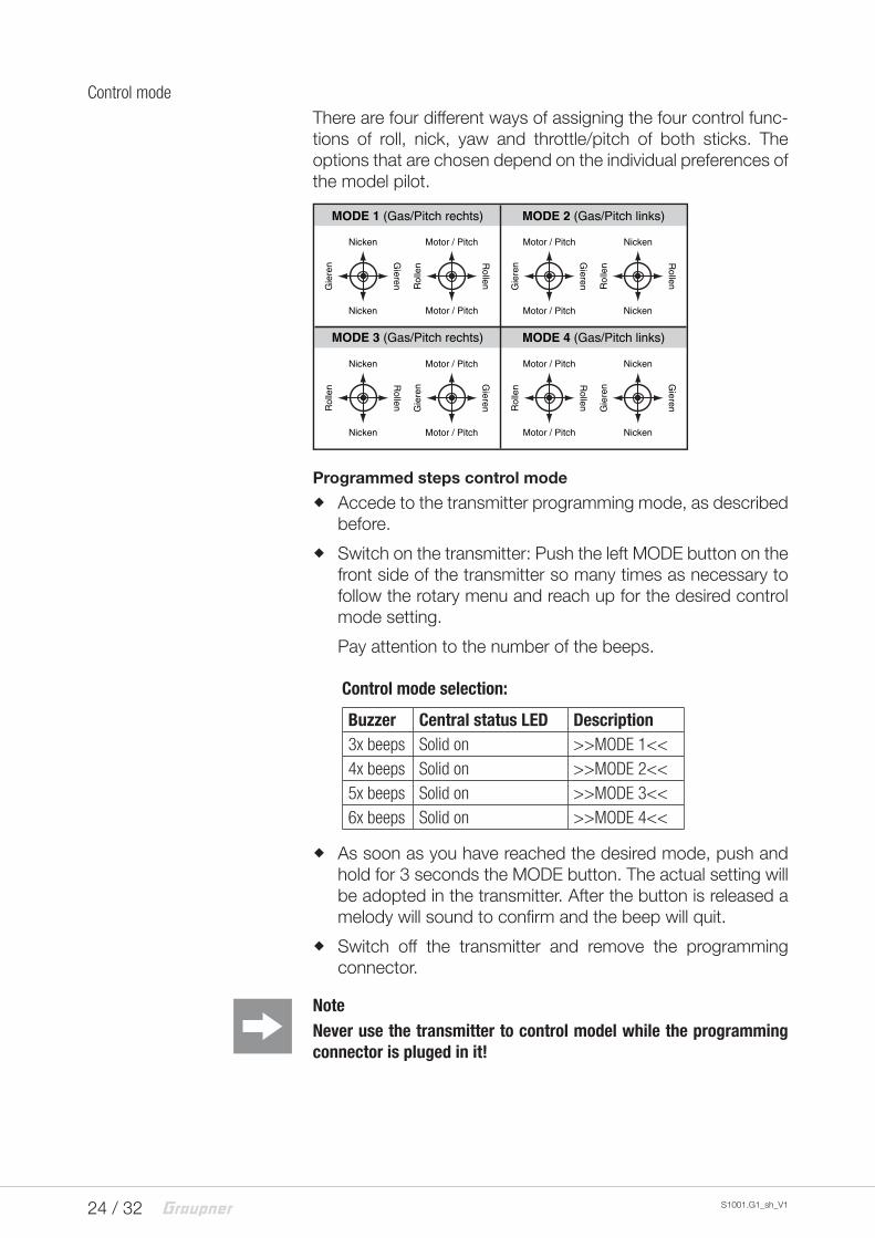
Control mode
There are four different ways of assigning the four control func-tions of roll, nick, yaw and throttle/pitch of both sticks. The options that are chosen depend on the individual preferences of the model pilot.
MODE 2 (Gas/Pitch links)
Nicken
Nicken
Gie
ren G
ieren
Motor / Pitch
Motor / Pitch
Rol
len R
ollen
Motor / Pitch
Motor / Pitch
Gie
ren G
ieren
Nicken
Nicken
Rol
len R
ollen
Nicken
Nicken
Rol
len R
ollen
Motor / Pitch
Motor / Pitch
Gie
ren G
ieren
Motor / Pitch
Motor / Pitch
Rol
len R
ollen
Nicken
Nicken
Gie
ren G
ieren
MODE 1 (Gas/Pitch rechts)
MODE 3 (Gas/Pitch rechts) MODE 4 (Gas/Pitch links)
Programmed steps control mode
� Accede to the transmitter programming mode, as described before.
� Switch on the transmitter: Push the left MODE button on the front side of the transmitter so many times as necessary to follow the rotary menu and reach up for the desired control mode setting.
Pay attention to the number of the beeps.
Control mode selection:
Buzzer Central status LED Description3x beeps Solid on >>MODE 1<<4x beeps Solid on >>MODE 2<<5x beeps Solid on >>MODE 3<<6x beeps Solid on >>MODE 4<<
� As soon as you have reached the desired mode, push and hold for 3 seconds the MODE button. The actual setting will be adopted in the transmitter. After the button is released a melody will sound to confirm and the beep will quit.
� Switch off the transmitter and remove the programming connector.
NoteNever use the transmitter to control model while the programming connector is pluged in it!
25 / 32S1001.G1_sh_V1
Fail Safe
The "Fail Safe" function determines the response of the receiver both by directly switching on the receiver system and when there is an interruption in transmission from the transmitter to receiver.
The functions connected to each receiver outputs can then ...
� ... after the receiver is powered on and until there is no valid signal from the transmitter, take the positions saved in the receiver. Completely independently from receiver settings "hold" or "pos".
NoteThe standard setting, until a change occurs, is the central posi-tion.
� ... in case of interference ...
- ... maintain the current position ("hold").
In case of transmission interruptions, all servos program-med to "hold" remain at their position which was last identified to be correct until a new, correct control signal is received by the receiver.
- ... after the preselected "failsafe delay" move to a selec-table position ("pos").
NOTESUse the safety potential of this option, in which you can program "Cut off in standard mode" in case of interferences.
Pay attention in the following described setting, that the copter motors cannot start accidentally during the test of the selected option.
Note that the chosen fail safe settings are saved in the receiver. The fail safe settings should be restored after changing a receiver and should be deleted in the previous receiver by resetting.
26 / 32 S1001.G1_sh_V1
Fail-safe variant selection
Push and hold the MODE button on the left of the LED panel while switching on the transmitter. Release the button after having switched the transmitter on and power the receiver pre-viously bound to the transmitter. The transmitter BIND LED should then light on yellow.
The transmitter is in Fail-safe mode. The different Fail-safe modes ("Hold", "on/off" and "Standard") can be reached by pus-hing briefly on the MODE button on the left of the LED panel. In rotation order you can change within the total four options:
active mode Status LED and buzzerFail Safe repeated 1x blink and 1x beepHold repeated 2x blinks and 2x beepsOff repeated 3x blinks and 3x beepsStandard repeated 4x blinks and 4x beeps
Mode "Fail-safe"
The transmitter beeps once after the first power on melody. The transmitter status LED blinks red.
In case of interference the servos take a preset position for a "hold"period of 0,75 seconds. Bring the functions in your copter on the respective associated transmitter controls at the SAME TIME to the desired positions and hold it until these positions are stored with a three to four seconds long press on the MODE button as fail-safe in the receiver settings, so that it can return for future reference. After releasing the button the status LED and the acoustic signal should indicate the actual transmitter status.
The transmitter is now again in control mode.
Check the settings by switching the transmitter off. Correct or repeat the programming if the functions of your copter do not move to the desired position.
Mode "Hold"
In case of transmission interruptions, all functions programmed to "hold" remain at their position which was last identified to be correct until a new, correct control signal is received by the recei-ver.
To save this selection push the MODE button for three to four seconds. After releasing the button the status LED and the acoustic signal should indicate the actual transmitter (power on) status.
The transmitter is now again in control mode. Otherwise repeat the process.
27 / 32S1001.G1_sh_V1
Fail-Safe OFF
With the "OFF" setting, over the course of a malfunction, the receiver stops transmitting control pulses for the relevant servo output The receiver switches the pulse line "off".
!ATTENTIONVerify by selecting "Fail-safe OFF" the reaction of your copter to the switch off of the impulse during the interference.
To save the selection push the MODE button for 3 to 4 seconds. After releasing the button the status LED and the acoustic signal should indicate the actual transmitter status.
The transmitter is now again in control mode. Otherwise repeat the process.
Standard mode
In this mode in case of interference only the throttle/pitch (chan-nel 1) moves to the position preset for this event, all other chan-nels remain in "hold". Switch to the Attitude mode and move the throttle stick and its trim to the desired position and push the MODE button for 3-4 seconds to save the selection. After relea-sing the button the status LED and the acoustic signal should indicate the actual transmitter status.
The transmitter is now again in control mode. Otherwise repeat the process.
NoteThrough the optionally available Smart-Box you can set the different options of the Fail-Safe individually. We suggest to set the channel 5 to 1500 µs and channel 1 to 1100 µs, so that during a Fail-Safe situa-tion the Attitude mode is active and motors stop.
28 / 32 S1001.G1_sh_V1
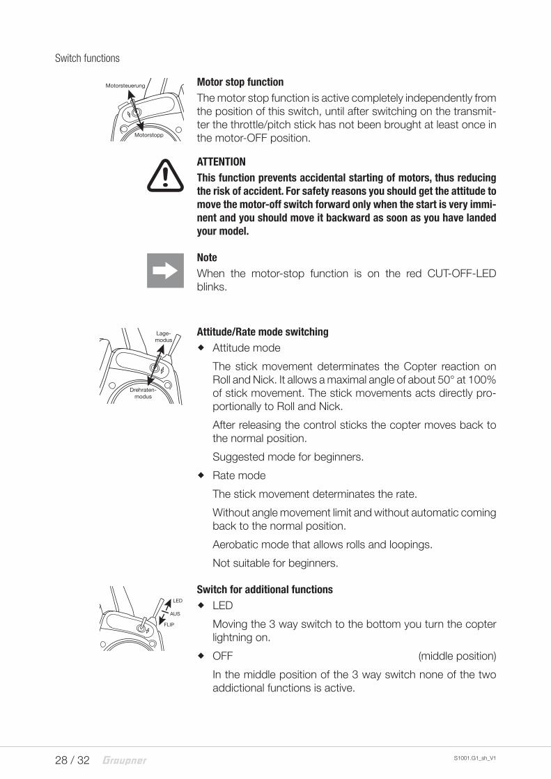
Switch functions
Motor stop functionThe motor stop function is active completely independently from the position of this switch, until after switching on the transmit-ter the throttle/pitch stick has not been brought at least once in the motor-OFF position.
!ATTENTIONThis function prevents accidental starting of motors, thus reducing the risk of accident. For safety reasons you should get the attitude to move the motor-off switch forward only when the start is very immi-nent and you should move it backward as soon as you have landed your model.
NoteWhen the motor-stop function is on the red CUT-OFF-LED blinks.
Attitude/Rate mode switching � Attitude mode
The stick movement determinates the Copter reaction on Roll and Nick. It allows a maximal angle of about 50° at 100% of stick movement. The stick movements acts directly pro-portionally to Roll and Nick.
After releasing the control sticks the copter moves back to the normal position.
Suggested mode for beginners.
� Rate mode
The stick movement determinates the rate.
Without angle movement limit and without automatic coming back to the normal position.
Aerobatic mode that allows rolls and loopings.
Not suitable for beginners.
Switch for additional functions � LED
Moving the 3 way switch to the bottom you turn the copter lightning on.
� OFF (middle position)
In the middle position of the 3 way switch none of the two addictional functions is active.
Motorsteuerung
Motorstopp
Lage-modus
Drehraten-modus
LED
FLIP
AUS
29 / 32S1001.G1_sh_V1
� FLIP (not available in the Rate mode.)
Pushing shortly the 3 way switch to the top activates the Auto-flip function in Attitude mode: the transmitter emits for a maximum of 5 seconds a continuous acoustic signal. During this time lapse move the roll or nick stick more than 50% of its travel. The copter will autonomously make a loop in the selected direction.
After the flip it is possible to have some little position movements (<10°)
Firmware updateThe programs and files which are also required for updating the transmitter combined into one software package can be down-loaded from www.graupner.de.
Download this software package from the Internet, and unpack it on your computer. All other information can be found in inter-net in the same page where the software package is available.
Transmitter firmware updates can be performed through the three pole DATA socket on the back side of the transmitter.
Suggested accessoriesFor an update of the transmitter software you need the available accessory USB interface so as an adapter cable.
Notes � Please note that compatible firmware is required for reliable
communication between the HoTT components. The programs and files that are required to update are therefore combined into a single file.
� The current firmware packet version can be found on the Internet at www.graupner.de.
� Only operate your transmitter using the current software version. these information can also be found at: www.graupner.de => Service & Support => Update and revision history for GRAUPNER HoTT components.
� Before each update check the transmitter battery charge status.
� Do not disconnect the link to the computer during an update! Make sure that the link between the transmitter and computer is operational.
� After each update, check if the model functions are correct.
You can find accessories on www.graupner.de.
30 / 32 S1001.G1_sh_V1
Transmitter software update
Perform update step by step:1. Connect the interface through the optional USB cable to a
PC.
2. If you have already installed the required drivers for the inter-face, the red LED on the interface board will light on.
3. Switch off the transmitter. Connect the DATA port of the swit-ched off transmitter to the USB interface board through the adapter cable. You can perform a firmware update by the "Firmware_Upgrade_gr_Studio" program in the program group "Devides" with the sub-program "HoTT devices".
4. Select "Auto download" or "File select" to prepare the actual firmware version.
5. In the next step it will be asked to switch the transmitter on: push the MODE button on the mz-10c transmitter while you switch it on. Release the MODE button as soon as the trans-mitter has been recognized: "Found target device ...".
6. The data transfer to the transmitter begins. During the update on the transmitter the LEDs light on: RATE, CH6, BIND and -100%.
7. The end of the data transfer will be indicated by the update program. The transmitter indicates the end of the transfer though the power on melody.
8. Switch off the transmitter and interrupt the USB connection to the PC.
Declaration of conformityS1001.G1 mz-10c HoTT
Graupner/SJ declares that the product is conform to EU norms.
EMV 2004/108/EC:
EN 301 489-1 V1.9.2
EN 301 489-17 V2.1.1
EN 62479:2010
LVD 2006/95/EC:
EN 60950-1 + A11 + A1 + A12 + A2:2013
R&TTE 1999/5/EC:
EN 300 328 V1.8.1
EN 62311:2008
31 / 32S1001.G1_sh_V1
DisposalThis symbol on the product, user manual or packaging indicates that this product must not be disposed of with other household waste at the end of its life. It must be handed over to the appli-cable collection point for the recycling of electrical and electronic equipment.
The materials are recyclable as marked. By recycling, material reusing or other forms of scrap usage you are making an import-ant contribution to environmental protection.
Batteries and accumulators must be removed from the device and disposed of at an appropriate collection point. Please inquire if necessary from the local authority for the appropriate disposal site.
Care and maintenanceThe product does not need any maintenance. Always protect it against dust, dirt and moisture.
Clean the product only with a dry cloth (do not use detergent!) lightly rub.
Warranty certificateThe company Graupner GmbH, Henriettenstrassee 96, 73230 Kirchheim/Teck grants from the date of purchase of this product for a period of 24 months. The warranty applies only to the material or operational defects already existing when you purcha-sed the item. Damage due to wear, overloading, incorrect acces-sories or improper handling are excluded from the guarantee. The legal rights and claims are not affected by this guarantee. Please check exactly defects before a claim or send the pro-duct, because we have to ask you to pay shipping costs if the item is free from defects.
The present construction or user manual is for informational pur-poses only and may be changed without prior notice. The cur-rent version can be found on the Internet at www.graupner.de on the relevant product page. In addition, the company Graupner has no responsibility or liability for any errors or inaccuracies that may appear in construction or operation manuals.
No liability can be accepted for printing errors.
P