Embed Size (px)
Citation preview

mz-10
ENC
op
yri
gh
t ©
Gra
up
ne
r/S
J G
mb
H
Manual
6 channel 2,4 GHz transmittermz-10 HoTT
No. S1042No. S1042.77

2 / 48 S1042_sh_V1

3 / 48S1042_sh_V1
Index
Introduction .............................................................................. 5Service centre ............................................................................ 5Intended use ............................................................................. 6
Target group ....................................................................................6Package content ........................................................................ 6Technical data ............................................................................ 7Symbol description .................................................................... 8Safety notes ............................................................................... 8
For your safety by handling the transmitter and the receiver .......9For your safety by handling the batteries ......................................9
Description of the transmitter ................................................. 10Package content ............................................................................10Connections and fixtures ..............................................................13
Attaching the transmitter neck-strap ........................................13Socket "DATA / S + -" ...................................................................13
Digital trim with an acoustic feedback .........................................13Transmitter preparation ........................................................... 14
Adjusting the length of the control sticks ....................................14Opening/closing the transmitter housing ....................................14Neutralizing the control sticks ......................................................16Brake spring and ratchet ...............................................................16Control sticks centering force .......................................................16Transmitter power supply .............................................................17
Installing the batteries ...............................................................17Optional power supply with battery pack .................................18Polarity of the mz-10 HoTT charging socket .............................18
Receiver power supply ..................................................................18Foreword ................................................................................. 19Transmitter startup .................................................................. 20
Transmitter status indications ......................................................20LED panel and keys .......................................................................21LED panel and keys .......................................................................22Use mode selection ......................................................................23binding ..........................................................................................24
Binding several receivers ...........................................................24Range and function test................................................................25
Range warning ...........................................................................27Use and setting ........................................................................ 28
Supported model types ................................................................28Receiver assignation ..................................................................29
Transmitter programming .............................................................30

4 / 48 S1042_sh_V1
Acceding to the transmitter programming mode .....................31Region setting ............................................................................31System menu - Control mode .....................................................32Servo direction and model type ................................................34Fail Safe ......................................................................................36Teacher/Student (T/S) ................................................................40Switch functions .........................................................................42
Firmware update ..................................................................... 44Transmitter software update ........................................................44
SIMPLIFIED DECLARATION OF CONFORMITY ............................ 46Notes on environmental protection ......................................... 47Care and maintenance ............................................................. 47Warranty ................................................................................. 47

5 / 48S1042_sh_V1
IntroductionThank you very much for purchasing a Graupner mz-10 HoTT trans-mitter.
Read the manual carefully to use the transmitter optimally and first of all to safely control your models. If you experience any trouble during operation, take the instructions to help or ask your dealer or Graupner Service Centre.
Due to technical changes, the information may be changed in this manual without prior notice. Be always updated by checking period-ically on our website, www.graupner.de to be always uptodate with the products and firmwares.
This product complies with national and European legal require-ments.
To maintain this condition and to ensure safe operation, you must read and follow this user manual and all the safety notes before using the product and you have to respect those notes also for future use!
NoteThis manual is part of that product. It contains important informa-tion concerning operation and handling. Keep these instructions for future reference and give it to third person in case you gave the product.
Service centreGraupner Central ServiceGraupner/SJ GmbHHenriettenstraße 96D-73230 Kirchheim/Teck
Servicehotline � (+49) (0)7021/722-130 Monday - Thursday: 9:15 am - 4:00 pm Friday: 9:15 am - 1:00 pm [email protected]
Graupner USA
3941 Park Dr Suite 20-571
El Dorado Hills, CA 95762
Website: www.graupnerusa.com
Phone: +1 855-572-4746
Email:[email protected]
Graupner in Internet For the service centers outside Germany please refer to our web site www.graupner.de.
6 / 48 S1042_sh_V1
Intended use This transmitter system must only be used for the purpose specified by the manufacturer for operation of remote control models with-out passengers. Any other type of use is impermissible and may cause significant property damage and/or personal injury. No war-ranty or liability is therefore offered for any improper use not cov-ered by these provisions.
In addition, it is explicitly pointed out that you must inform yourself about the laws and regulations applicable at your respective starting point before starting the remote control operation. Such conditions may differ from state to state, but this must be followed in every case.
Note
Read through this entire manual before you attempt to install or use the transmitter.
Target groupThe item is not a toy. It is not suitable for children under 14. The operation of the transmitter must be performed by experienced modelers. If you do not have sufficient knowledge about dealing with radio-controlled models, please contact an experienced mod-eler or a model club.
Package content• Transmitter mz-10 HoTT
• 4 batteries AA type (not rechargeable)
• Battery box
• Programming connector
• Receiver GR-12L (only with S1042)
• Manual
NoteGraupner/SJ constantly works on the development of all products; we reserve the right to change the item, its technology and equip-ment.

7 / 48S1042_sh_V1
Technical data
Transmitter mz-10 HoTT
Frequency band 2,4 … 2,4835 GHz
Modulation FHSS
Controller 16-Bit-Microcontroller
Transmitting power 100 mW
Model memory 1
Control functions 5 functions of which 4 can be trimmed
Teacher/Pupil function Wireless
Temperature range -10 … +55 °C
Antenna Integrated
Operating voltage 3,4 … 6 V
Power consumption ca. 130 mA
Charging socket only for rechargeable batteries (optionally available)
Dimensions ca. 184 x 259 x 96 mm
Weight approx. 630 g
Receiver GR-12L (only included with S1042)
Frequency band 2,4 … 2,4835 GHz
Modulation FHSS
Temperature range -15 … +70 °C
Antenna 1 x wire 145 mm of which Antenna 30 mm
Operating voltage (2.5) 3.6 ... 8.4 V
Power consumption approx. 70 mA
Dimensions approx. 36 x 21 x 10 mm
Weight approx. 7 g

8 / 48 S1042_sh_V1
Symbol descriptionAlways observe the information indicated by these warning signs. Particularly those which are additionally marked with the words CAUTION or WARNING.
!The signal word WARNING indicates the potential for serious injury, the signal word CAUTION indicates possibility of lighter injuries.
The signal word Note indicates potential malfunctions.
Attention indicates potential damages to objects.
Safety notes
!These safety instructions are intended not only to protect the prod-uct, but also for your own and other people’s safety. Therefore please read this section very carefully before using the product!
• Do not leave the packaging material lying around, this could be a dangerous toy for children.
• Persons, including children, with reduced physical, sensory or mental capabilities, or lack of experience or knowledge, or not capable to use safely the transmitter must not use the trans-mitter without supervision or instruction by a responsible per-son.
• Operation and use of radio-controlled models needs to be learnt! If you have never operated a model of this type before, start carefully and make yourself familiar with the model's reactions to the remote control commands. Proceed always responsibly.
• Protect all equipment from dust, dirt, moisture. All equipment must be protected from vibration as well as excessive heat or cold. The models may only be operated remotely in normal outside temperatures such as from -10°C to +55°C.
• Always use all your HoTT components only with the latest firmware version.
• If you have questions which cannot be answered by the oper-ating manual, please contact us or another expert in the field.
9 / 48S1042_sh_V1
For your safety by handling the transmitter and the receiver
!WARNINGAlso while programming the transmitter, make sure that a motor connected in the model cannot accidentally start. Disconnect the fuel supply or drive battery beforehand.
!CAUTIONAvoid every kind of short-circuit in all sockets of the transmitter and of the receiver! Risk of fire! Use only the suitable connectors. In no case the electronic component of the transmitter or of the receiver may be changed or modified. Any interference will void the authorization.
NoteDuring transport protect the model and the transmitter from dam-ages.
For your safety by handling the batteries
!CAUTION• Protect the batteries from dust, moisture, heath and vibra-
tions. Only use in dry locations.
• Do not use any damaged battery.
• Batteries may not be heated, burned, short-circuited.
• If handled improperly, there is a danger of fire, explosion, irri-tation and burns.
• Leaked electrolyte is caustic and should not be touched or come into contact with your eyes. In case of emergency, rinse with a large quantity of water and consult a Med. Doctor.
• Do not try to recharge the batteries included in the package! Those are non-rechargeable batteries.
• Stock the batteries in dry and fresh conditions.
• Dispose of the battery in the proper disposal centers.

10 / 48 S1042_sh_V1
Description of the transmitter
Package content
mz-10
7 5
1
2
3 4
68971011
12
13 14
1 antenna integrated in the case2 Eyelet for neck strap
3 D/R switch (switch function between 70 % and 100 % servo travel of the control functions 2, 3 and 4)
4 TRAINER switch (see use mode)5 Right-hand control stick6 ARROW button7 Trim8 ON/OFF switch9 LED indicators field10 MODE button11 Left-hand control stick12 Control channel 513 Carrying handle14 Central status LED

11 / 48S1042_sh_V1
Alternatively, the transmitter mz-10 HoTT can be equipped with a firmware version suitable for the operation of copters. See section "Firmware Updates" on the last pages of this manual for more infor-mation.
mz-10
7 5
1
2
3 4
68971011
12
13 14
1 antenna integrated in the case2 Eyelet for neck strap3 Switch between Attitude and Rate mode4 FLIP / OFF / LED5 Right-hand control stick6 ARROW button7 Trim - active in Attitude mode only8 ON/OFF switch9 LED indicators field10 MODE button11 Left-hand control stick12 Switch normal use / motor stop13 Carrying handle14 Central status LED

12 / 48 S1042_sh_V1
mz-10
1 11 1 11
1 2 3 4 1
1 Case screws2 Battery case cover
3
Data socket to connect- a programming connector- an optional SMART BOX- a Bluetooth module- an interface adapter to update the transmitter
4 Charging socket
!CAUTIONThe charge port is intended to charge an optional battery pack. Never use it with non rechargeable batteries.

13 / 48S1042_sh_V1
Connections and fixtures
Attaching the transmitter neck-strap
On the upper side of the transmitter there is an eyelet which can be used to hook a neck-strap.
Socket "DATA / S + -"
For the socket "DATA / S + -“ there are 3 possible connection options:
1. With the optionally available SMART-BOX, allows the use of other HoTT functions
2. With the optionally available USB adapter, allows the connection between transmitter and PC for a firmware update
3. With the optionally available Bluetooth module allows the trans-mission of telemetry data to a compatible smartphone or tablet.
Note for the polarity of the socket "DATA / S + -“:
S = signal line (orange)
+ = Plus line (red)
- = Minus line (brown or black)
You can find more information about the listed accessories on www.graupner.de.
Digital trim with an acoustic feedbackThe two control sticks have digital trimming. Briefly touch the trim-ming switch to move the neutral position of the control stick by a specific value with each click. If it is held, the trimming moves in the corresponding direction with increasing speed.
The adjustment is made "audible" by tones of varying levels. It is therefore easy to find the middle position during the use of the model. If you go past the middle position, a brief pause is inserted.
The trim positions are automatically saved.
The digital trim reacts to a trim lever movement only if the transmit-ter is switched on.
NoteIn the copter version, the digital trim is effective only in the front switch position of the Attitude/Rate mode changeover switch (3) mounted on the right upper side of the transmitter housing.

14 / 48 S1042_sh_V1
Transmitter preparation
Adjusting the length of the control sticksLength of both control stick can be adjusted. Hold down the bottom half of the knurled grip, and loosen the screwed connection by turn-ing the top part.
You can now lengthen or shorten the control stick by screwing it up or down. Then clamp the top and bottom part of the grip by rotat-ing them against each other.
Opening/closing the transmitter housingThe transmitter should be opened only in the following cases:
• If a self centering stick has to be converted in non self centering
• If a non self centering stick has to be converted in self centering
• To set the control stick centering force
!CAUTIONNever switch the transmitter on while the housing is open. Risk of short-circuit! Risk of fire! Remove the batteries or the recharge-able battery pack before opening the transmitter case!
Open step by step1. Before opening the housing switch the transmitter off.2. Open the battery case.3. Remove the battery box lifting it from one side and gently release
it from the Velcro-type tape.4. Unplug the connector.5. Unscrew the eight screws with a cross-screwdriver, see the rep-
resentation in the previous double-page. 6. Hold both housing halves with both hands and let the screws fall
on a proper surface turning the transmitter upside-down.7. Rotate the lower half carefully and fold it to the bottom.
NoteCables connect the lower half of the housing with the upper part electronic components. This connection must not be damaged! Do not touch the electronic boards.

15 / 48S1042_sh_V1
Closing step by step1. Check if the upper and the lower part of the transmitter housing
are correctly coupled and the tiny cables are properly placed.2. Screw the housing screws in their original position.3. Reconnect the battery box.
1
2
2
3
3
43
43
1 Transmitter antenna integrated in the handle
2 Adjust screws for brake spring (outer) and ratchet (inner)
3 Stick self centering force adjust screws
4 Screw to convert from neutralizing to non neutralizing and vice versa

16 / 48 S1042_sh_V1
Neutralizing the control sticks
Neutralizing step by step
Locate in the left control stick gimbal the screw surrounded by a white circle in the picture.Turn the screw toward the inside of the transmitter until the relevant control stick can move freely from stop to stop, or turn it outward until the control stick resets itself independently.
NoteThe right control stick gimbal is specular to the left one, so that here the screw is located left under the middle.
Brake spring and ratchetThe outboard screw of the two marked in the figure adjust the brak-ing force.
The inboard screw adjusts the strength of the ratchet for the respec-tive control stick.
NoteThe right control stick gimbal is specular to the left one, so that here the screws are located right on the top side.
Control sticks centering forceThe control sticks' restoring force can also be adjusted. The adjust-ment is located next to the return springs.
By turning the respective adjust screw the spring force can be adjusted:
Right turn = return harder
Left turn = return softer
NoteThe right control stick gimbal is specular to the left one, so that here the screws are located left in the middle.

17 / 48S1042_sh_V1
Transmitter power supplyThe mz-10 HoTT transmitter normally includes normally 4 non-re-chargeable batteries. These are NOT rechargeable.
Installing the batteries
!WARNINGAlkaline batteries (dry batteries) should not be recharged. Acute risk of explosion!
NotePay attention when inserting the batteries to the correct position and make sure the contacts are solid.
Interruptions of the power supply to the transmitter during the use of the models can lead to big danger for your self and for other peo-ple!
Replacing the batteries step by step1. Locate the battery case in the back of the transmitter.2. Slide the battery case cover.3. Remove the cover.4. The battery box is fixed in the battery case through Velcro tape.5. Lift the lower side of the battery box carefully.6. Loosen the connection between the battery box and the trans-
mitter by carefully pulling the battery plug.7. Remove the used batteries from the battery box.8. Replace the batteries with full batteries of the AA type.9. Reconnect the plug to the socket in the inside of the battery case.
(Plus pole = red cable, minus pole = brown or black cable).10. Place the battery box in the battery case.11. Close the battery case with the cover.12. If you have inadvertently connected the plug in wrong position,
the transmitter will not switch on.

18 / 48 S1042_sh_V1
Optional power supply with battery pack
Instead of batteries you can use rechargeable NiMH batteries. For the recharge you can use the charging port located on the back of the transmitter.
!WARNINGFollow the safety instructions included with the batteries!
Polarity of the mz-10 HoTT charging socket
Make sure that the polarity of the charge cable is the same as the charge port. The charge cables of other manufacturers have often reversed polarity. For this reason, you should only use original Graupner charging cable.
NoteThe charging socket comes standard with a protection switch that protects against polarity reversal. Original Graupner automatic chargers recognize the battery charge. In order to prevent damage to the protection switch and to the other components, charging current should never exceed 1 A.
Receiver power supplyIf not marked with "B", no specific port is provided for the battery connection. We recommend that you connect the power supply to the socket close to the servos already connected to the receiver.
AttentionWhen selecting and connecting a power supply, be aware that although the operating range of the receiver ranges from 3.6 to 8.4 V. However, practically all of the previously marketed servos, speed controllers, gyros, etc. as well as many which are offered today have a permissible operating voltage range of 4.8 to 6 V.
!CAUTIONNever connect the power supply connector horizontally to the receiver as shown in the right-hand picture. Risk of short-circuit! Risk of fire!

19 / 48S1042_sh_V1
ForewordThe mz-10 HoTT transmitter can be used to control aircraft, land and watercraft models or alternatively to control copters, depending on the firmware version that has been imported via firmware update. The following sections of this manual are accordingly marked with model type symbols. All four symbols in a row therefore always mean "common property".
Otherwise, only the symbols suitable for the particular model type are represented, for example, the coper symbol for the copter mod-els of the transmitter mz-10 HoTT.
NoteFirmware updates of the transmitter are carried out via the back DATA port using a laptop or PC with Windows 7 ... 10. You will also need a USB interface, order no. 7168.6, and adapter lead, order no. 7168.6A or 7168.S, which are available separately.
The programs and files required can be found in the Download area for the corresponding products at www.graupner.de. See section "Firmware Updates" on the last pages of this manual for more infor-mation.
20 / 48 S1042_sh_V1
Transmitter startup
Transmitter status indications
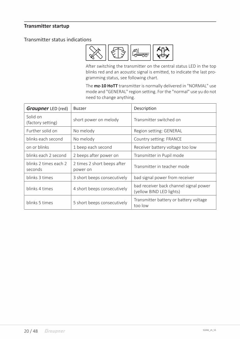
After switching the transmitter on the central status LED in the top blinks red and an acoustic signal is emitted, to indicate the last pro-gramming status, see following chart.
The mz-10 HoTT transmitter is normally delivered in "NORMAL" use mode and "GENERAL" region setting. For the "normal" use yu do not need to change anything.
Graupner LED (red) Buzzer Description
Solid on(factory setting) short power on melody Transmitter switched on
Further solid on No melody Region setting: GENERAL
blinks each second No melody Country setting: FRANCE
on or blinks 1 beep each second Receiver battery voltage too low
blinks each 2 second 2 beeps after power on Transmitter in Pupil mode
blinks 2 times each 2 seconds
2 times 2 short beeps after power on Transmitter in teacher mode
blinks 3 times 3 short beeps consecutively bad signal power from receiver
blinks 4 times 4 short beeps consecutively bad receiver back channel signal power (yellow BIND LED lights)
blinks 5 times 5 short beeps consecutively Transmitter battery or battery voltage too low

21 / 48S1042_sh_V1
LED panel and keys
After switching on the transmitter the LEDs on the LED panel blink or light for approx. 5 seconds to indicate the actual correct settings.
1 2 5
CH1 CH2 CH3 CH4 CH5
BIND 2AILE DELTAV-TAIL
3 4
1 MODE button1. Push and hold while switching on the transmitter ...
... starts the firmware-update
... activates the Fail-safe setting2. Transmitter switched on
Binding transmitter and receiver
2 Servo reverse channel (CH) 1 - 5red LED blinking = normal directionred LED solid on = reverse
3 BIND LEDindicates if transmitter and receiver are bound(lights only by active receiver's back channel)
4 2AILE, DELTA or V-Tail2AILE- and DELTA-LED blink = no mixer active2AILE LED solid on, DELTA LED blinks = Aileron mixer active (2AILE)2AILE LED blinks, DELTA LED solid on = Delta mixer active2AILE- and DELTA LED solid on = V-Tail mixer active (V-TAIL)
5 Arrow buttonChanges in the programming mode and pages between different settings in rotation at each pression

22 / 48 S1042_sh_V1
LED panel and keys
After switching on the transmitter the LEDs on the LED panel blink or light for approx. 5 seconds to indicate the actual correct settings.
1 2 3
8
6
Cut-o� Rate CH6 CH7 CH8
BIND -100% +100%CH9
4 4 5
7 9
1 MODE button1. Push and hold while switching on the transmitter ...
... starts the firmware-update
... activates the Fail-safe setting2. Transmitter switched on
Binding transmitter and receivershort push takes a snapshot through the cameraPush for about 2 seconds: select video channel
2 Cut-off (operated with left upper switch)Red LED blinks = Motors-OFF function is onRed LED off = Motors-OFF function is off
3 Rate (operated with right upper switch)Red LED lights = Rate mode is onRed LED off = Rate mode is off
4 CH6 + CH7Red LED on: upper right switch on LED position
5 CH8Red LED off/lights = shows the video resolution depending on the used video system
6 Arrow buttonShort push starts and stops video reproductionPush for about 2 seconds changes the video resolution
7 BIND LEDYellow LED on = the transmitter receives the feedback signal from the last bound receiver
8 -100 %Green LED blinks = camera snapshot
9 +100 %Green LED blinks = Video recording on
1 + 7 pressed togetherStarts and stops the range test

23 / 48S1042_sh_V1
Use mode selection
Normal mode
Teacher mode
Pupil mode
To change the use mode, move the "TRAINER" switch in the desired position with the transmitter in switched off, push and hold the MODE button and switch subsequently the transmitter on.
• The last selected model settings, control mode so as an eventu-ally set receiver binding remain unchanged. The binding of a receiver is however possible only in "NORMAL" mode.
• The use of a model in teacher or pupil mode is only possible in connection with the Trainer system.
• After every activation of the "NORMAL" use mode:
ശ The transmitter will be in program mode "Fail safe".
ശ The buzzer beeps each 2 seconds and contemporary the sta-tus LED blinks.
ശ The country setting, even if changed to "FRANCE", will be set to "GENERAL" so as the position of the digital trim will be set to "neutral".
ശ The warning threshold for transmitter battery will be set to 4,5 V, as long this has been changed through the optional SMART BOX.
If the fail safe settings saved in the receiver have to be retained, switch the transmitter off and after a short pause again on. Other-wise proceed as described in "Fail safe".
NoteThe mz-10 HoTT transmitter remains after a conversion of the con-trol mode in the last selected use mode until this will be changed. This is completely independent from the occurred setting of the TRAINER switch and even after switching on again the transmitter.
24 / 48 S1042_sh_V1
binding
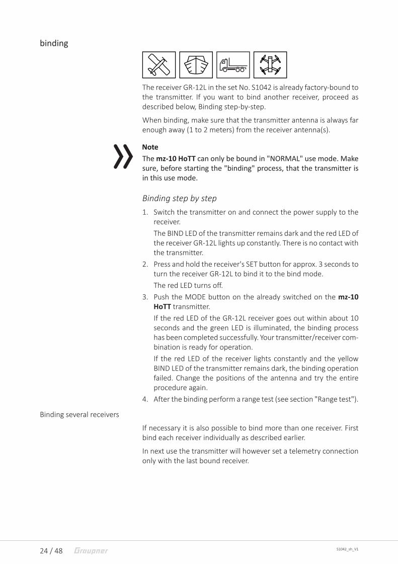
The receiver GR-12L in the set No. S1042 is already factory-bound to the transmitter. If you want to bind another receiver, proceed as described below, Binding step-by-step.
When binding, make sure that the transmitter antenna is always far enough away (1 to 2 meters) from the receiver antenna(s).
NoteThe mz-10 HoTT can only be bound in "NORMAL" use mode. Make sure, before starting the "binding" process, that the transmitter is in this use mode.
Binding step by step1. Switch the transmitter on and connect the power supply to the
receiver. The BIND LED of the transmitter remains dark and the red LED of the receiver GR-12L lights up constantly. There is no contact with the transmitter.
2. Press and hold the receiver's SET button for approx. 3 seconds to turn the receiver GR-12L to bind it to the bind mode.The red LED turns off.
3. Push the MODE button on the already switched on the mz-10 HoTT transmitter. If the red LED of the GR-12L receiver goes out within about 10 seconds and the green LED is illuminated, the binding process has been completed successfully. Your transmitter/receiver com-bination is ready for operation.If the red LED of the receiver lights constantly and the yellow BIND LED of the transmitter remains dark, the binding operation failed. Change the positions of the antenna and try the entire procedure again.
4. After the binding perform a range test (see section "Range test").
Binding several receivers
If necessary it is also possible to bind more than one receiver. First bind each receiver individually as described earlier.
In next use the transmitter will however set a telemetry connection only with the last bound receiver.

25 / 48S1042_sh_V1
Sensors eventually installed in the model have to be connected to this receiver, because the transmitter will indicate only the values coming from the back channel of the last bound receiver. All other receiver work in parallel to the last receiver bound to the transmit-ter.
AttentionIf one of these "last but not least" connected receivers is to be used as the main receiver, this receiver has to be reconnected as "last" receiver. Otherwise the LED of the receiver signals correct reception and the servos react to control commands, but there is still no telemetry connection. Also, neither the range and function test described below nor the correct range warning is carried out.
Range and function test
When the range test starts, through contemporaneously pushing the left MODE and the right arrow keys, the transmitter output power decreases significantly, then you can perform a function test in a distance not higher than 100 m. After the 90 second range test, the transmitter switches back to full output, and the signal tone stops. You can always interrupt the range test by pushing for approx-imately 1 - 2 seconds the MODE and the arrow buttons.
It is useful to have an assistant who helps you.
NoteThe range test works only with the last bound receiver. Only with it there is a feedback channel for the telemetry connection.
Range test step by step1. Install the already bound receiver in the model.2. Place the model on a flat surface (cement, mowed lawn or
ground) so that the receiver antennas are at least 15 cm above the ground. It may therefore be necessary to place a support underneath the model during the test.
3. Switch the transmitter on and wait until the receiver indicate according to the manual a correct function connection. Only now the servos can be moved.
4. Hold the transmitter at hip level at a slight distance from your body.

26 / 48 S1042_sh_V1
However, do not aim directly at the model with the antenna inte-grated into the right handle of the transmitter, but tilt the trans-mitter downwards or turn to the side so that this handle is approximately at right angles to the model during the test oper-ation.
5. Make sure that the transmitter is in "NORMAL" use mode. Push contemporaneously the left MODE and the right arrow keys until the transmitter starts beeping quickly.
6. During the 90 seconds, walk away from the model and move the sticks. If you notice an interruption in the connection at any time within a distance of about 50 m, try to reproduce it.
7. If possible, switch on an existing motor, in order to additionally check the interference resistance.
8. Move further away from the model until it does not respond per-fectly any more.
9. At this location, wait for the remainder of the test period with the still operable model or push simultaneously the left MODE and the right arrow keys for about 1 - 2 seconds to stop the test. As soon as the range test has finished, the model should react to the controls movements. If this is not 100 % the case, do not use the system and contact your Service at Graupner/SJ GmbH.
10. Perform a range test before each flight, and simulate all servo movements that could occur during the flight. In order to guar-antee a safe model operation, the range must always be at least 50 m on the ground.
!CAUTION
• Never start a range test on the transmitter during normal model operation! The model cannot be controlled any more depending on the distance from the transmitter. Risk of injury!
• For physical reasons, the antenna integrated into the right han-dle of the transmitter forms a small field strength in a straight extension. In particular, if the model to be controlled is located at a greater distance and / or below the pilot location, the transmitter must be held so that the handle is approximately at a right angle to the model.
Antenna integatedin the handle
Antenna integatedin the handle

27 / 48S1042_sh_V1
Range warning
In general, an acoustic range warning is emitted once the receiver signal in the feedback channel becomes too weak. Since the trans-mitter's output is significantly higher than the receiver, the model can always be operated safely. For safety reasons however, the model distance should be reduced until the signal silences.
If the acoustic warning signal does not quit in spate the reduced dis-tance, the use of the model should be interrupted immediately and the transmitter should be checked. Eventually the transmitter's under-voltage or receiver's temperature warning are active. Then the battery should be charged or the receiver temperature should be checked.
NoteIn case the transmitter cannot set a connection to a proper back channel or during the use an existing connection is interrupted, the transmitter mz-10 HoTT BIND LED turns off and the buzzer indicates it with a 4 times beep signal (back channel missing), after that with a 3 times beep following (transmission interference to the receiver). Contemporaneously the status LED blinks 3 times.

28 / 48 S1042_sh_V1
Use and setting
Supported model typesWith the standard firmware of the mz-10 HoTT transmitter, water and land vehicles, as well as surface planes with up to two aileron control servos for standard models, as well as V-tail and flying-wing / delta models with two aileron/elevator servos can be controlled:
• NO mixer active:
1 centralaileron servofor both wings
Elevator
Rudder
• Mixer "2AILE“: two aileron servos
Elevator
Rudder
Right aileron
Left aileron
• Mixer "DELTA“: Flying wing/delta models
left
rightAile+Ele
Rudder
Aile+Ele
• Mixer "V-TAIL“: V-Tailleft
rightRudder+Elevator
Copter after importing the copter firmware by firmware update.
29 / 48S1042_sh_V1
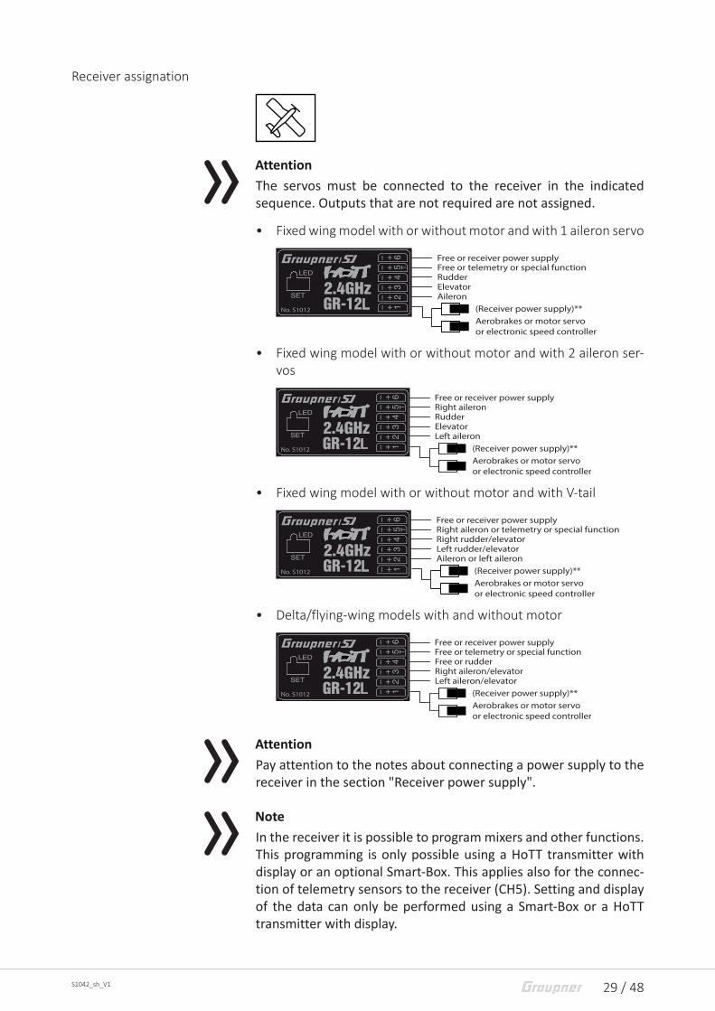
Receiver assignation
AttentionThe servos must be connected to the receiver in the indicated sequence. Outputs that are not required are not assigned.
• Fixed wing model with or without motor and with 1 aileron servo
Rudder
AileronElevator
Free or telemetry or special functionFree or receiver power supply
(Receiver power supply)**Aerobrakes or motor servoor electronic speed controller
LNo. S1012
• Fixed wing model with or without motor and with 2 aileron ser-vos
Rudder
Left aileronElevator
Right aileronFree or receiver power supply
(Receiver power supply)**Aerobrakes or motor servoor electronic speed controller
LNo. S1012
• Fixed wing model with or without motor and with V-tail
Right rudder/elevator
Aileron or left aileronLeft rudder/elevator
Right aileron or telemetry or special functionFree or receiver power supply
(Receiver power supply)**Aerobrakes or motor servoor electronic speed controller
LNo. S1012
• Delta/flying-wing models with and without motor
Free or rudder
Left aileron/elevatorRight aileron/elevator
Free or telemetry or special functionFree or receiver power supply
(Receiver power supply)**Aerobrakes or motor servoor electronic speed controller
LNo. S1012
AttentionPay attention to the notes about connecting a power supply to the receiver in the section "Receiver power supply".
NoteIn the receiver it is possible to program mixers and other functions. This programming is only possible using a HoTT transmitter with display or an optional Smart-Box. This applies also for the connec-tion of telemetry sensors to the receiver (CH5). Setting and display of the data can only be performed using a Smart-Box or a HoTT transmitter with display.
30 / 48 S1042_sh_V1
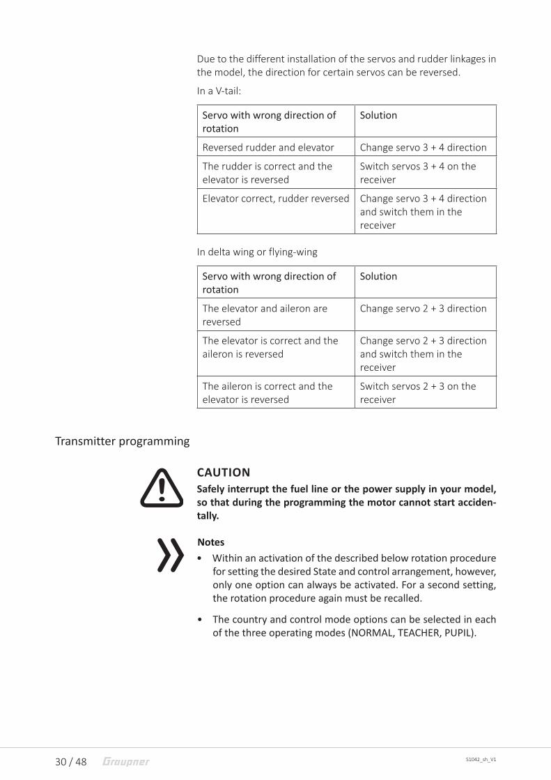
Due to the different installation of the servos and rudder linkages in the model, the direction for certain servos can be reversed.
In a V-tail:
Servo with wrong direction of rotation
Solution
Reversed rudder and elevator Change servo 3 + 4 direction
The rudder is correct and the elevator is reversed
Switch servos 3 + 4 on the receiver
Elevator correct, rudder reversed Change servo 3 + 4 direction and switch them in the receiver
In delta wing or flying-wing
Servo with wrong direction of rotation
Solution
The elevator and aileron are reversed
Change servo 2 + 3 direction
The elevator is correct and the aileron is reversed
Change servo 2 + 3 direction and switch them in the receiver
The aileron is correct and the elevator is reversed
Switch servos 2 + 3 on the receiver
Transmitter programming
!CAUTIONSafely interrupt the fuel line or the power supply in your model, so that during the programming the motor cannot start acciden-tally.
Notes• Within an activation of the described below rotation procedure
for setting the desired State and control arrangement, however, only one option can always be activated. For a second setting, the rotation procedure again must be recalled.
• The country and control mode options can be selected in each of the three operating modes (NORMAL, TEACHER, PUPIL).
31 / 48S1042_sh_V1
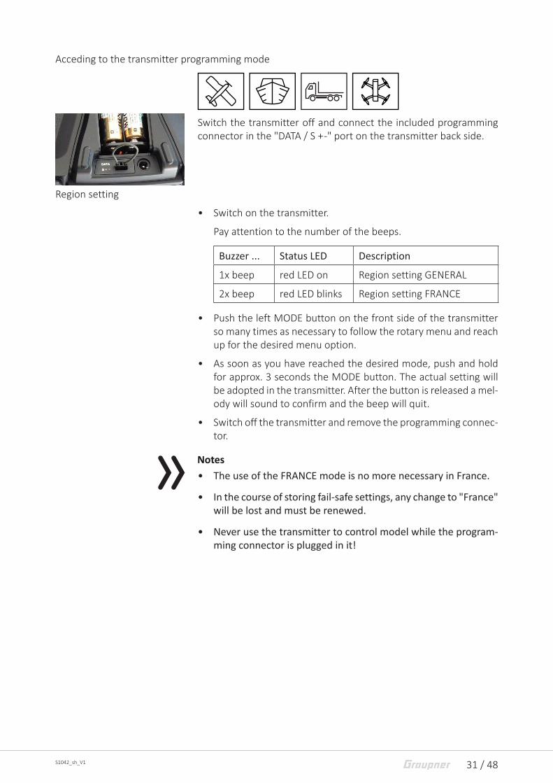
Acceding to the transmitter programming mode
Switch the transmitter off and connect the included programming connector in the "DATA / S + -" port on the transmitter back side.
Region setting
• Switch on the transmitter.
Pay attention to the number of the beeps.
Buzzer ... Status LED Description
1x beep red LED on Region setting GENERAL
2x beep red LED blinks Region setting FRANCE
• Push the left MODE button on the front side of the transmitter so many times as necessary to follow the rotary menu and reach up for the desired menu option.
• As soon as you have reached the desired mode, push and hold for approx. 3 seconds the MODE button. The actual setting will be adopted in the transmitter. After the button is released a mel-ody will sound to confirm and the beep will quit.
• Switch off the transmitter and remove the programming connec-tor.
Notes• The use of the FRANCE mode is no more necessary in France.
• In the course of storing fail-safe settings, any change to "France" will be lost and must be renewed.
• Never use the transmitter to control model while the program-ming connector is plugged in it!

32 / 48 S1042_sh_V1
System menu - Control mode
There are four different ways of assigning the four control functions of aileron, elevator, rudder and throttle or airbrake flaps of a wing model or roll, nick, yaw and motor/pitch control of a copter of both sticks. The options that are chosen depend on the individual prefer-ences of the model pilot.
Control mode
MODE 2 (throttle left)
elevator
elevator
rudd
er
rudder
full throttle
idle
aile
ron aileron
full throttle
idle
rudd
er
rudder
elevator
elevator
aile
ron aileron
elevator
elevator
aile
ron aileron
full throttle
idle
rudd
er
rudder
full throttle
idle
aile
ron aileron
elevator
elevatorru
dder
rudder
MODE 1 (throttle right)
MODE 3 (throttle right) MODE 4 (throttle left)
Control mode
MODE 2 (throttle at left stick)
left
right
forward
back
forward
back
left
right
forward
back
left
right
forward
back
left
right
MODE 1 (throttle at right stick)
MODE 3 (throttle at right stick) MODE 4 (throttle at left stick)

33 / 48S1042_sh_V1
Control mode
MODE 2 (Throttle/Pitch left)
Nick
Nick
Yaw
Yaw
Throttle/Pitch
Throttle/Pitch
Rol
l Roll
Throttle/Pitch
Throttle/Pitch
Yaw
Yaw
Nick
Nick
Rol
l Roll
Nick
Nick
Rol
l Roll
Throttle/Pitch
Throttle/PitchY
aw
Yaw
Throttle/Pitch
Throttle/Pitch
Rol
l Roll
Nick
Nick
Yaw
Yaw
MODE 1 (Throttle/Pitch right)
MODE 3 (Throttle/Pitch right) MODE 4 (Throttle/Pitch left)
Programmed steps control mode1. Accede to the transmitter programming mode, as described
before.2. Push the left MODE button so many times as necessary to follow
the rotary menu and reach up for the desired control mode set-ting.Pay attention to the number of the beeps.
3x beep red LED on >>MODE 1<<
4x beep red LED on >>MODE 2<<
5x beep red LED on >>MODE 3<<
6x beep red LED on >>MODE 4<<
3. As soon as you have reached the desired mode, push and hold for 3 seconds the MODE button. The actual setting will be adopted in the transmitter. After the button is released a melody will sound to confirm and the beep will quit.
4. Switch off the transmitter and remove the programming connec-tor.
NoteNever use the transmitter to control model while the programming connector is plugged in it!

34 / 48 S1042_sh_V1
Servo direction and model type
Servo direction
With the exception of CH5 for the 2AILE model type, the direction of rotation can be set separately for each of the servo 1 ... 5 as described below under "Programming step-by-step".
In the "REVERSE" line of the LED field, the direction of rotation is indi-cated separately for each of the channels 1 ... 5:
Red LED blinking = Direction "normal",
Red LED solid on = Direction "reverse".
The LED indicator lights for about 5 seconds after exiting the selec-tion menu so as every transmitter switching on.
NoteThrough the available optional SMART BOX the servo can be indi-vidually adapted to the model necessity in the RX SERVO menu in the receiver.
Model Type
In the mz-10 HoTT transmitter you can select one of the standard configurations. The setting is carried out as described below under "Programming step-by-step".
"Normal"
Elevator and rudder so as aileron if available are operated by only one servo each. All the five control functions of the mz-10 HoTT transmitter act separately on the servos connected to the receiver.

35 / 48S1042_sh_V1
"2AILE"
For models with 2 aileron servos.
By aileron actuation the servos connected to the outputs 2 and 5 work in parallel. The aileron trim acts on both servos.
NoteA conversion of "CH5" has in this case no effect.
"DELTA"
For delta and flying-wing model with one servo each wing.
The aileron and elevator control are carried out through the servos connected to the channels 2 and 3. The mixer for ailerons and ele-vator are actuated by the transmitter. The aileron and elevator trim acts on both servos.
"V-TAIL"
For models with V-tail and 1 or 2 aileron servo.
The elevator and rudder are controlled by two separately-articulated rudders arranged in a V-shape connected to channel 3 and 4. The mixer for rudder and elevator is actuated by the transmitter. The rudder and elevator trim acts on both servos.
The related active setting will be indicated after the transmitter switch-on for about five seconds through the LED field on the trans-mitter.
Programming step-by-step1. Switch on the transmitter without programming connector.
These options can be selected in each of the three operating modes (NORMAL, TEACHER, PUPIL).
2. Press the arrow button to the right of the LED field for at least 2 seconds. After releasing, a short beep will be heard and the CH1 LED in the "REVERSE" LED line flashes.
3. Press the arrow button to the right of the LED field until the LED of the desired option flashes.Between the seven possible setting options CH1 ... CH5, 2AILE and DELTA is changed in the rotary process.(The LEDs of options CH1 ... CH5 flash red, the LEDs of options 2AILE and DELTA are green.)
4. To change the status of the desired option push the MODE but-ton. The blinking LED lights solid on.
5. Use the arrow button to the right of the LED field to move to the next option and change the next option.
6. You can always interrupt exit this menu by pushing for at least 2 seconds the arrow button.

36 / 48 S1042_sh_V1
A short beep is emitted after release. 7. As after every transmitter switching on, the seven LEDs light and/
or blink for approx. 5 seconds to indicate the actual selected set-tings.
Fail Safe
The "Fail Safe" function determines the response of the receiver both by directly switching on the receiver system and when there is an interruption in transmission from the transmitter to receiver.
NoteBy default, the center position is specified for all receiver outputs until the fail-safe positions are saved for the first time.
The servos connected to the receiver outputs 1 to 5 can then ...
• ... after the receiver is powered on and until there is no valid sig-nal from the transmitter, take the positions saved in the receiver. Completely independently from receiver settings "hold" or "pos".
• ... in case of interference ...
ശ ... ("HOLD").
In case of transmission interruptions, all servos programmed to "hold" remain at their position which was last identified to be correct until a new, correct control signal is received by the receiver.
ശ ... after the preselected "failsafe delay" move to a selectable position ("pos").
Notes• Use this safety option to program a Fail Safe for at least the
throttle position in gas models while idling, or to program the motor function to stop with electric models, or to hold with heli-copter models.
• Pay attention in the following described setting, that an already connected motor does not start accidentally during the test of the selected option.

37 / 48S1042_sh_V1
• Note that the chosen fail safe settings are saved in the receiver. The fail safe settings should be restored after changing a receiver and should be deleted in the previous receiver by resetting.
• In the course of storing fail-safe settings, any change to "France" will be lost and must be renewed.
Fail-safe variant selectionNoteThe fail-safe setting is only possible in connection with the activa-tion of the "NORMAL" use mode.
Set the transmitter to the programming mode Fail-SafeSwitch off the transmitter and move the TRAINING switch on the transmitter right side in the "NORMAL" position. Push and hold the MODE button on the left of the LED panel while switching on the transmitter. Release the button after having switched the transmit-ter on and power the receiver previously bound to the transmitter. The transmitter BIND LED should then light on yellow.
The transmitter is now in Fail-safe mode. Switch between the four options by briefly pressing the MODE button on the left of the LED field in the rotary process:
push the MODE button
active mode Status LED and buzzer
0x Fail Safe repeated 1x blink and 1x beep
1x Hold repeated 2x blinks and 2x beeps
2x Off repeated 3x blinks and 3x beeps
3x Standard repeated 4x blinks and 4x beeps
Mode "Fail-safe"
In case of interference the servos take a preset position for a "hold"pe-riod of 0,75 seconds.

38 / 48 S1042_sh_V1
Programming step-by-step1. Select the desired mode2. Use the controls on the transmitter to move the servos of the
model to the desired positions and hold them. 3. Press the MODE button to the left of the LED field for three to
four seconds to store these items in the receiver.After releasing the button the status LED and the acoustic signal should indicate the actual transmitter (power on) "control mode" status.
4. Release the control elements.5. Check the settings by switching the transmitter off.
If the servos do not move to the desired positions, repeat the procedure.
Mode "Hold"
In case of transmission interruptions, all servos programmed to "hold" remain at their position which was last identified to be correct until a new, correct control signal is received by the receiver.
Programming step-by-step1. Select the desired mode2. Press the MODE button for three to four seconds.
After releasing the button the status LED and the acoustic signal should indicate the actual transmitter (power on) "control mode" status.
3. Check the settings by switching the transmitter off. If the servos do not remain in the most recently reached posi-tions, repeat the procedure.
Fail-Safe "OFF"
With the "OFF" setting, over the course of a malfunction, the receiver stops transmitting control pulses for the relevant servo output The receiver switches off of the pulse line in a manner of speaking.
AttentionAnalogue servos and many digital servos no longer experience resis-tance to the ongoing control pressure after control pulses stop and are moved out of their position at higher or lower speed.
Programming step-by-step1. Select the desired mode2. Press the MODE button for three to four seconds.

39 / 48S1042_sh_V1
After releasing the button the status LED and the acoustic signal should indicate the actual transmitter (power on) "control mode" status.
3. Check the settings by switching the transmitter off. If analogue servos can not be moved by hand, repeat the proce-dure.
Standard mode
In this mode in case of interference only the throttle servo (channel 1) moves to the position preset for this event, all other channels remain in "hold".
Programming step-by-step1. Move the throttle stick and its trim to the desired position.2. Press the MODE button to the left of the LED field for three to
four seconds to store these items in the receiver.After releasing the button the status LED and the acoustic signal should indicate the actual transmitter (power on) "control mode" status.
3. Release the throttle stick.4. Check the settings by switching the transmitter off.
If the throttle servo does not move to the desired position, repeat the procedure.

40 / 48 S1042_sh_V1
Teacher/Student (T/S)
An mz-10 HoTT transmitter can be combined with any suitable HoTT transmitter for a wireless Teacher-Pupil system. However, note the following:
NoteCompletely independently from the related teacher transmitter defaults in a pupil transmitter type mz-10 HoTT the training model MUST ALWAYS be bound to the pupil transmitter. In addiction it is absolutely essential for correct training that the model memory active in the teacher model is not bound to any receiver.
Preparing for training mode
Teacher transmitter
The training model must be programmed with all its functions includ-ing trimming and any mixed functions in a model memory of the HoTT teacher transmitter. The model provided for training must therefore be completely controllable by the teacher transmitter.
To conclude preparations, bind the training model to the pupil trans-mitter.
From a mz-10 HoTT teacher transmitter all the five channels will be transmitted to the pupil transmitter.
Pupil transmitter
After the training model has been completely programmed into the teacher transmitter, and its full operational capacity has been checked by a practical test, the training model can be bound to the pupil transmitter mz-10 HoTT in "NORMAL" mode.
The "Control mode" can be adapted to the pupil's preferences, even if the common conventions to follow are:
Channel Function
1 Motor throttle
2 Aileron
3 Elevator
4 Rudder
In an mz-10 HoTT pupil transmitter the active mixers 2AILE and/or DELTA have to be switched off so as the servo direction of all servos (CH1 -CH5) have to be set to "normal".

41 / 48S1042_sh_V1
Later in the preparations it is possible to adapt the servo direction, especially of CH1, to the habits of the student.
Preparing teacher and pupil transmitter
Teacher transmitter
Bring the mz-10 HoTT teacher transmitter in "TEACHER" use mode or program the other teacher transmitter accordingly to its manual.
Pupil transmitter
Bring the mz-10 HoTT pupil transmitter in "PUPIL" use mode or pro-gram the other pupil transmitter accordingly to its manual.
NoteThe mz-10 HoTT transmitter remains after a conversion of the con-trol mode, completely independently from the occurred setting of the TRAINER switch and even after switching on again the transmit-ter, in the last selected use mode until this will be changed.
Binding both transmittersDuring the binding process, the distance between the two transmit-ters should not be too small (up to 2m). However, always keep a suf-ficient distance from the HoTT receiver already bound to the pupil transmitter. In case of too small distance because of the back chan-nel redundancies it is possible that some errors are signaled.
Programming
Pupil transmitter
Push and hold the MODE button on the switched on mz-10 HoTT pupil transmitter until the first beep is emitted or activate the bind-ing process accordingly to the other HoTT pupil transmitter manual.
Teacher transmitter
Push and hold the MODE button on a mz-10 HoTT teacher transmit-ter until the first beep is emitted or activate the binding process accordingly to the other HoTT teacher transmitter manual.
If the binding process is successful, both transmitters will indicate each in its way the correct binding. By transmitter type mz-10 HoTT e.g. through the light up of the yellow BIND LED. Otherwise change the distance and repeat the process.

42 / 48 S1042_sh_V1
T/S mode
NoteBefore starting trainer mode for the operational model, be sure to check whether all the functions have been correctly transferred.
In the canter switch position ("TEACHER") of a teacher's transmitter mz-10 HoTT the teacher's transmitter controls all control functions. In the upper, self-centering, switch position ("PUPIL"), the pupil can control the model as long as the switch is held by the teacher in this position.
During the training mode teacher and pupil can maintain a comfort-able distance. The so-called call range (max. 50 m) should not be exceeded. Nor should there be any other persons between teacher and student. These can affect the range of the return channel used for connecting the two transmitters. In such a case you should pro-vide a smaller distance between both transmitters. If it does not help, you should immediately stop the use of the model and search for the reason.
!WARNINGThe teacher transmitter should never be switched off during the use! Without teacher transmitter the model cannot be controlled. In case that during the control by the pupil transmitter the con-nection to this transmitter is interrupted, the TRAINER switch on the mz-10 teacher transmitter has to be moved as soon as possible again to the "TEACHER" position, so that the transmitter can take back the control of the model. Other teacher transmitters take in such a case automatically the control of the model.
Switch functions
Motor stop function
The motor stop function is active completely independently from the position of this switch, until after switching on the transmitter the throttle/pitch stick has not been brought at least once in the motor-OFF position.
!ATTENTIONThis function prevents accidental starting of motors, thus reducing the risk of accident. For safety reasons you should get the attitude to move the motor-off switch forward only when the start is very imminent and you should move it backward as soon as you have landed your model.
Motor control
Motor cut-off

43 / 48S1042_sh_V1
NoteWhen the motor-stop function is on the red CUT-OFF-LED blinks.
Attitude/Rate mode switching
• Attitude mode
The stick movements determinate the Copter reaction on Roll and Nick. It allows a maximal angle of about 50° at 100% of stick movement. The stick movements acts directly proportionally to Roll and Nick.
After releasing the control sticks the copter moves back to the normal position.
Suggested mode for beginners.
• Rate mode
The stick movements determinate the rate.
Without angle movement limit and without automatic coming back to the normal position.
Aerobatic mode that allows rolls and loopings.
Not suitable for beginners.
Switch for additional functions
• LED
Moving the 3 way switch to the bottom you turn the copter light-ning on.
• OFF (middle position)
In the middle position of the 3 way switch none of the two addic-tional functions is active.
• FLIP (not available in the Rate mode.)
Pushing shortly the 3 way switch to the top activates the Auto-flip function in Attitude mode: the transmitter emits for a maxi-mum of 5 seconds a continuous acoustic signal. During this time lapse move the roll or nick stick more than 50% of its travel. The copter will autonomously make a loop in the selected direction.
After the flip it is possible to have some little position movements (<10°)
Attitudemode
Rate mode
LED
FLIP
OFF

44 / 48 S1042_sh_V1
Firmware update
Firmware updates of the transmitter are carried out via the back DATA port using a laptop or PC with Windows 7 ... 10. You will also need a USB interface, order no. 7168.6, and adapter lead, order no. 7168.6A or 7168.S, which are available separately.
The programs and files required can be found in the Download area for the corresponding products at www.graupner.de.
Download this software package from the Internet, and unpack it on your computer. All other information can be found in Internet in the same page where the software package is available.
Connect the adapter lead to the USB interface. The polarity of the plug-in system cannot be reversed. Note the small chamfers on the sides. Do not use force, the plug should click into place easily.
The update is carried out via the "HoTT device" program section of the program "Firmware_Upgrade_gr_Studio". Please follow the notes of the software. The further procedure is also described in detail in the manual contained in the data package. You can also download these from the download page of the product at www.graupner.de.
Transmitter software update
Perform update step by step
• Before each update check the transmitter battery charge status. Connect the interface through the included USB cable to a PC.
• Do not disconnect the link to the computer during an update! Make sure that the link between the transmitter and computer is operational.
• Plug the other end of the adapter cable into the jack marked "DATA" on the back of the transmitter. Make sure that the orange cable is plugged into the left, marked as "S", and the brown or black cable on the right PIN marked with a "-". Do not apply force. The plug should be fully inserted.
• Select "Auto download" or "Open file" to select between the cur-rent firmware versions.
• Select the file "mz-10_ ... bin" if you want to keep the default firmware or to return to it or the file "MZ-10C_ ... bin" for the copter version.

45 / 48S1042_sh_V1
• Finally you will be asked to switch the transmitter on: push the MODE button on the mz-10 HoTT transmitter while you switch it on. Release the MODE button as soon as the transmitter has been recognized: "Found target device ...".
• The data transfer to the transmitter begins. During the update on the transmitter the LEDs light on: CH2, CH3, BIND and 2AILE.
• The end of the data transfer will be indicated by the update pro-gram. The transmitter indicates the end of the transfer though the power on melody.
• Switch off the transmitter and interrupt the USB connection to the PC.
• After each update, check if the model functions are correct.

46 / 48 S1042_sh_V1
SIMPLIFIED DECLARATION OF CONFORMITYGraupner/SJ hereby declares that the S1042 mz-10 HoTT complies with the Directive 2014/53/EU.
The full text of the EU Declaration of Conformity is available at the following Internet address: www.graupner.de

47 / 48S1042_sh_V1
Notes on environmental protectionIf this symbol is on the product, instructions for use or packaging, it indicates that the product may not be disposed with normal house-hold waste once it has reached the end of its service life. It must be turned over to a recycling collection point for electric and electronic apparatus.
Individual markings indicate which materials can be recycled. You make an important contribution to protection of the environment by utilizing facilities for reuse, material recycling or other means of exploiting obsolete equipment.
Batteries must be removed from the unit and disposed of separately at an appropriate collection point. Please inquire if necessary from the local authority for the appropriate disposal site.
Care and maintenanceThe product does not need any maintenance. Always protect it against dust, dirt and moisture.
Clean the product only with a dry cloth (do not use detergent!) lightly rub.
WarrantyGraupner/SJ GmbH, Henriettenstrassee 96, 73230 Kirchheim/Teck grants from the date of purchase of this product for a period of 24 months. The warranty applies only to the material or operational defects already existing when you purchased the item. Damage due to misuse, wear, overloading, incorrect accessories or improper han-dling are excluded from the guarantee. The legal rights and claims are not affected by this guarantee. Please check exactly defects before a claim or send the product, because we have to ask you to pay shipping costs if the item is free from defects.
These operating instruction are exclusively for information purposes and are subject to change without prior notification. The current version can be found on the Internet at www.graupner.de on the relevant product page. In addition, the company Graupner/SJ has no responsibility or liability for any errors or inaccuracies that may appear in construction or operation manuals.
Not liable for printing errors.
P