Embed Size (px)
Citation preview


S 19
SIGNALLING RELAYS & CABLES
Issued in November 2009
INDIAN RAILWAYS INSTITUTE OF
SIGNAL ENGINEERING & TELECOMMUNICATIONS SECUNDERABAD - 500 017

S-19 SIGNALLING RELAYS AND CABLES
Prepared By D. Raju IES6 Umesh V Kulkarni IES 4
Checked By P. Sreenivasu , LS 2
Approved By Ch. Mohan, SPS
DTP P.V.Surya Narayana, JE-I (D) No.of pages 141 Date of Issue November , 2009 Revision No A2
© IRISET
http://www.iriset.ac.in
CONTENTS
S.No CHAPTER PAGE NO
1. Introduction 1
2. Signalling Relays 10
3. Shelf Type DC Line & Track Relays 18
4. Plug In Type DC Line Relays (Metal-Carbon contacts) 27
5. Plug In Type DC Line Relays (Metal-Metal Contacts ) 40
6. Lamp Proving Relays 68
7. Time Element Relays 75
8. Plug In Type Track Relays 79
9. Siemen’s Thermo Flasher Unit 84
10. Slow Acting Relays 86
11. DC Polar Relay 89
12. Signalling Cables 91
Annexure-A SEM Extract of Para 614 on underground Cables 106
Annexure-B Cable Testing Proforma 108
Annexure-C Relay Specifications and Relay Data Sheets 109
“ This is the Intellectual property for exclusive use of Indian Railways. No part of this publication may be stored in a retrieval system, transmitted or reproduced in any way, including but not limited to photo copy, photograph, magnetic, optical or other record without the prior agreement and written permission of IRISET, Secunderabad, India”

INTRODUCTION
Page 1 SIGNALLING RELAYS & CABLES
CHAPTER 1: INTRODUCTION
1.1 INTRODUCTION Signalling systems used more mechanical signalling components. Gradually they were
reduced with the usage of electric point machines, electromagnetic relays and electric locks.
The two essential components used in this Electrical signalling are "Relays" & Cables ". These find their application in modern control systems also.
Relay scan be classified based on type of contacts material used as-
a) Metal to Metal contact b) Metal To Carbon (Silver impregnated graphite)
Based on the usage, the relays can be classified as-
a) Line relay b) Track Relays c) Lamp Proving Relays d) Timer Relay e) Flasher Relay f) Contactor Relays
Based on polarity requirement of a relay relay can be classified as –
a) Polar Relay b) Neutral Relay
Details may be seen in Chapter1 to 10
Cables for signalling use are mainly of two types
a) Signalling Cable b) Power Cable
Details may be seen in Chapter No-12 Let us study certain symbols, abbreviated nomenclatures.
1.2 SYMBOLS AND NOMENCLATURE: Symbols are brief sketches which represent the character and main function of the equipment.
These are usually accompanied by numerical and/or alphabetical terms to specify and identify them with a particular device or its component.
Nomenclature is a collection of simple and brief designations of apparatuses to describe their nature and location.
In an electrical circuit diagram straight lines represent the wire connections between the specified devices or their components with their symbols and nomenclatures. These also include the wire terminals, the separation between locations as well as the interconnections between power sources, controls and the operated loads.
The power signalling systems on our railways conform to two practices: (1) The British Railway practice and (2) the continental or German practice. Therefore we adopt two different languages each peculiar to one of the two practices. There are some few common elements between them but broadly they differ very sharply.

INTRODUCTION
IRISET Page2
To study the various symbols and nomenclatures, the signalling gears may be broadly classified as: -
(1) Signals (2) Points (3) Level crossing gates (4) Locks and (5) Controls. The standard symbols adopted in the British practice are covered in the British standard
specification for wiring symbols and written circuits No.376 part (11).
As far as possible, the first letter of the description of apparatus is chosen for the nomenclature. But where the descriptions of more than one apparatus start with the same letter, all but one equipment is represented by arbitrarily chosen letters. MEANING OF LETTERS - DESCRIPTIVE AND DESIGNATIVE AS USED
Alphabet Descriptive term
(prefix) Apparatus (Last letter)
Descriptive & designative
A Approach, automatic -- Approach
B Block, Bolt Block instruments Block, Button, Positive energy, Bridge, Back
C Checking or proving Contact
Common, changer, counter, Correspondence, changer Circuit controller, code,
D Clear (green) Decoding -- Proceed indication of a signal,
detector, decoding,
E Light: heat (externally applied)
(Electric lamp illuminating), earth
Earth, eastward, electric light, element, equipment,
F Fog Fogging apparatus, (example: Detonator placer)
Traffic, front, frequency, fuse
G -- Lightning arrestor Ground, gate, signal aspect H Caution (yellow) Capacitor Home, approach indication of a signal I -- Indicator --
J Time (delayed action) Rectifier Skate, dual control
K Indicating or detecting Indicator (visual) Indicator
L Locking, left, Lock Left, locking, lever, light, lock valve, lock
M Magnet Motor Magnetic, marker, manual
N Normal (push button or key)
Release (switch, P B & key) Normal, north, northbound Negative,
O Retarder Resistor Order, operating, off, overload, out
P Repeater Lever latch or trigger contact
Pole, power, purple, push, repeating, primary
Q Treadle or bar Local coil of a Double coil relay Local or secondary coil,
R Reverse, right, red Relay or contactor Right, red, reverse, relay, rail, stop indication of sig.
S Stick -- South, stick, storage, south word
T Track circuit Transformer, transmitter
Track, time, train, telephone, transformer, transmitter,

BRITISH SYMBOLS
Page 3 SIGNALLING RELAYS & CABLES
Alphabet Descriptive term
(prefix) Apparatus (Last letter)
Descriptive & designative
U Route Route indicating Retarder unit.
V Train stop Train stop apparatus Train stop (track element E. P. stop)
W Point Point operating apparatus Switch, west, white, westward
X Audible indicator Audible indicator (buzzer) Cross, interlocking, bell, buzzer.
Y Slotting Disengaging apparatus Slot, yellow, hold, clear.
Z Special unit (to be explained on plan) Zone, use for any special term.
1.2.2: BRITISH SYMBOLS
N Switch / Knob Contact in Normal Position
Switch / Knob Contact in Reverse PositionR
Relay Coil (Name of Relay is written inside the rectangle)R1 R2
DescriptionSymbol
Closed Contact when Relay is in Energised condition
Slow to release Relay
Slow to pickup Relay
Double Coil RelayR1 R3
A C Immunised Relay
Time Element Relay front Contact (Energised Condition)
(Front Contact)
(Back Contact)Closed Contact when Relay is in de-energised condition
R2 R4
S.No.
1
2
3
4
5
6
7
8
9
10
INTRODUCTION
IRISET Page4
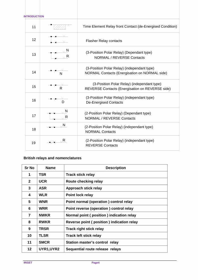
Flasher Relay contacts
NORMAL / REVERSE Contacts
Time Element Relay front Contact (de-Energised Condition)
R
N(3-Position Polar Relay) (Dependant type)
N NORMAL Contacts (Energisation on NORMAL side)(3-Position Polar Relay) (independant type)
R REVERSE Contacts (Energisation on REVERSE side)(3-Position Polar Relay) (independant type)
D De-Energised Contacts (3-Position Polar Relay) (independant type)
NORMAL Contacts
R (2-Position Polar Relay) (independant type)REVERSE Contacts
R
N
N
NORMAL / REVERSE Contacts
(2-Position Polar Relay) (independant type)
(2-Position Polar Relay) (Dependant type)
11
12
13
14
15
16
17
18
19
British relays and nomenclatures
Sr No Name Description
1 TSR Track stick relay
2 UCR Route checking relay
3 ASR Approach stick relay
4 WLR Point lock relay
5 WNR Point normal (operation ) control relay
6 WRR Point reverse (operation ) control relay
7 NWKR Normal point ( position ) indication relay
8 RWKR Reverse point ( position ) indication relay
9 TRSR Track right stick relay
10 TLSR Track left stick relay
11 SMCR Station master’s control relay
12 UYR1,UYR2 Sequential route release relays

SIEMENS SYMBOLS
Page 5 SIGNALLING RELAYS & CABLES
1.3 SIEMENS PRACTICE: On our Railways, in Siemens installations, circuits are made using Siemens (German) symbols but nomenclature according to British practice is used. SYMBOLS AND NOMENCLATURES In Siemens relay interlocking, circuitry is drawn in German symbols with British nomenclature.
(Top Relay)Interlocked Relay Reverse Coil
Neutral Relay
Symbol Description
Interlocked Relay Normal Coil(Bottom Relay)
Track Relay
Track Repeater Relay
Block Relay in Automatic Territory
Time Element RelayT
Normal Position of Neutral Relay is picked up
Normal Position of Neutral Relay is Dropped
Normal Position of Interlocked Relay is picked up(Normal Coil)
S.No.
10
9
8
7
5
6
4
3
2
1

INTRODUCTION
IRISET Page6
(Reverse Coil)Normal Position of Interlocked Relay is Dropped
Make Contact
Break Contact
Neutral Relay , Normally pick up Make Contact(Front Contact)
Neutral Relay , Normally pick up Break Contact(Back Contact)
Neutral Relay , Normally drop make contact (Back Contact)
Neutral Relay , Normally drop, Break Contact(Front Contact)
Interlocked Relay , Normally pick up, make Contact(Front Contact)
Interlocked Relay , Normally pick up Break Contact(Back Contact)
Interlocked Relay , Normally drop make Contact(Back Contact)
Interlocked Relay , Normally drop, Break Contact(Front Contact)
19
18
17
16
15
14
12
13
11
21
20

REVIEW QUESTIONS
Page 7 SIGNALLING RELAYS & CABLES
Note : The arrow on the left with a base line indicates the normal condition of the relay.

INTRODUCTION
IRISET Page8
Relay Contacts: -
In the Siemen’s Relay interlocking systems, the control of signalling gears is exercised generally in three and more stages. This is unlike the British practice. Also at each stage more relays are used for control as the relay integrity needs to be proved at each stage. The relays used in the three stages of control, viz. (i) initiation (ii) control and (iii) locking have their nomenclature including in them the stage of control, the gear controlled and the sequential order of the relay used at that stage. Some of the relays nomenclature and abbreviation used in the siemen’s practice of controls are as follows: - Relays nomenclatures
RELAY NOMENLATURES
GNR Signal button relay
GNCR Signal button checking relay
SH-GNR Shunt signal button relay.
CO-GGNR Common button relay for calling-on signals
EGGNR/ERNR Common button relay to replace any signal at 'ON"
UNR Route Button relay.
UNCR Route button checking relay
EUYNR Emergency sub-route release button relay.
EUYZ Emergency sub-route release operation counter.
EUUYNR Emergency ( full ) route release button relay.
EUUYZ Emergency (full ) route release operation counter
EUUYNCR Emergency (full ) route release button checking
relay
EUYR Emergency route release relay
( common for sub route and full route cancellation)
WNR Point button relay.
WNCR Point button checking relay
WWNR Common point button relay.
(when point zone track circuits are up)
EWNR Emergency Common point button relay
(when point zone track circuit is down)
EWZ Emergency points operation-counter
WLR Point locking relay
WJR Point time delay relay
WR Point contractor relay (heavy duty contractor relay)
CHYNR Crank handle slot release button relay.

REVIEW QUESTIONS
Page 9 SIGNALLING RELAYS & CABLES
RELAY NOMENLATURES
CHYRNR Crank handle slot return button relay
CHKLR Crank handle key lock relay.
XYNR Gate control release Button relay
XYRNR Gate control Return Button Relay
XCKR Gate closed indicating relay.
XOKR Gate opened indicating relay.
NNCR/NCR All buttons checking relay (common for all buttons)
Review Questions
Subjective
1) What is the meaning of letter A, B, C, G ? 2) What is the meaning of letter X, F, W, O? 3) What is the symbol of point controlling relay in Siemens? 4) What is the symbolic difference between neutral relay and interlocked relay In Siemens? 5) What is the full form of TRSR, TSR, TR, TPR, and TLSR?
Objective
1) WJR stands for ----------------------------------------------------------------- 2) WR relay stands for ------------------------------------------------ 3) XOKR stands for ------------------------------------------------------------------------- 4) Show a symbol of front contact of normally drop neutral relay --------------------- 5) Show a symbol of flasher relay contact ----------------------------

SIGNALLING RELAYS
IRISET Page10
CHAPTER 2: SIGNALLING RELAYS 2.1 INTRODUCTION
A relay is an electromagnetic device, which is used to convey information from one circuit to another circuit through a set of contact i.e. front or back contact.
Constructional and electrically, relays may be divided into DC and AC relays, because the means by which the electrical energy in the coil is converted in to mechanical Energy in order to move the contacts are fundamentally different. In DC type, the contacts are carried on an armature, forming part of a magnetic circuit in which a field is set up by the current flowing in the coils. In AC types, the contacts are attached by a link mechanism to a metal sector, disc or cylinder in which currents are induced by the alternating magnetic field produced by the currents in the coils.
Every endeavor has been made to explain the action of each type of relay in the simplest possible manner.
Relays are sophisticated switch gears used for remote control and succession control of various electrical equipment. In present days they are widely used because they are capable of protecting the controlled equipment from cross feeding and overloading even as they cater for speedy operations.
Most of the relays in present day signaling are electromagnetic devices, although some of the relays control circuits through electronic components like diode/transistors/ Integrated Chips etc Railway signaling relays are unique in that:
(a) They operate on low voltage and current (b) They are more articulate as, according to their special features, they can work under
restrictive conditions and in any specified manner. Virtually they can cater for all situations while contributing to speed and accuracy in operations.
2.2 CLASSIFICATION OF SIGNALLING RELAYS:
(a) According to the method of their mounting or fixture, they are classified as:
(i) Shelf type: Relays, which are loosely kept on shelves. (ii) Plug in type : Relays, which are plugged into a pre- wired plug boards.
(b) According to their connection and usage, they are classified as:
(i) Track relays : Relay, which is directly connected to the track, to detect the
presence of vehicle. (ii) Line Relays : Other than track relay all are line relays. Relays connected to the
selection circuit.
(c) According to their vitality or importance in ensuring train working safety, they are classified as:
(i) Vital Relays: All relays used for traffic control such as signal, point, controls,
track detection etc. (ii) Non-vital Relays : Relays, which operate control aids and accessories like
warnings, buzzers, Indications etc.

CLASSIFICATION OF RELAYS
Page 11 SIGNALLING RELAYS & CABLES
(d) According to their special provisions to ensure reliability of their contacts, they are classified as:
(i) Proved type : are those whose normalization after each operation shall be
proved in circuit controlled by their contacts. Contacts in which both the springs have metal surfaces on their tips. They may get fused due to high sparking current across them during operation. These may prevent relay normalization and causes unsafe condition in traffic control. To avoid this, proving of relay normalization after each operation is necessary.
(ii) Non - proved type : Need not to be proved to have been normalized after each
operation as their contacts have at least one non-fusible contact (carbon contact)
(e) According to their feed source, relays are broadly classified as:
(i) DC relays: The relay, which requires DC power supply for its operations are, called DC relays. Among the DC relays.
o DC neutral relays : This relay closes the same set of contacts on
energization, with Normal polarity or Reverse polarity supply.
o Polar Relays : This relay closes different set of contacts when energized with Reverse polarity supply. They may or may not have contact to close when de-energized.
(ii) AC Relay : AC Induction motor track relays. Time element relays, flashing
indication control etc.
(iii) Electronic Relays : DC relays with electronic components in them are called electronic relays.
2.3 DC Neutral Relay
Fig: 2.1 DC NEUTRAL RELAY

SIGNALLING RELAYS
IRISET Page12
Each Relay has usually one or two coils with a hollow center to accommodate a core. The coils are made up of a large numbers of turns of small gauge soft drawn copper wire. The two coils can be connected in series or parallel according to the requirement of relay resistance. The ends of the coils are terminated on binding post to which the control wires are connected. Each coil is placed around a core of specially selected Iron or steel having high permeability and low retentivity. The core should be susceptible to magnetism and at the same time should have little residual magnetism. The cores are connected at the top by a yoke to complete the magnetism coupling between two ends of coils. The bottom of each core is equipped with a large steel or Iron block known as pole piece or face.
A flat piece of Iron or steel called armature is supported by brackets, which are securely fastened to the pole piece. The armature, yoke, and the pole pieces are also made of specially selected iron or steel of the same quality as the core. The armature carries the metallic spring contacts, which are insulated from it.
The circuit through the coils of the relay is closed. It sets up a magnetic flux through the core, yoke and the armature. The flux passing between the armature and pole faces causes the armatures get attracted to the pole faces and armature picks up and closes front contacts. When the circuit is opened the magnetic flux collapses and the armature drops away by gravity from the pole faces, the front contacts break and back contacts close. The front and back contacts of the relay can be utilised to make or break other circuits. Two stop pins of non-magnetic material are fixed either on the armature or pole faces so that the armature cannot come in contact with the pole faces. It is essential to maintain a small air-gap between the armature and pole faces so that low value of residual magnetism may not retain the armature in picked up position and causes the relay to fail to drop away with a break in its control circuit. 2.3.1 GENERAL USAGE DC Neutral line relays are most commonly used for Railway Signalling controls and detection. Among them, plug-in type relays are preferred in larger installations for space considerations. Shelf type relays are also in use, mostly in wayside stations. There are many DC Neutral line relays in use with special features such as
(i) Delayed operation (ii) Biased DC control (iii) DC control unaffected by AC interference currents (iv) Getting latched in operated condition till further feeding, and others.
Usage of DC polar relays is mostly in conjunction with block instruments that control traffic between stations. AC line relays are almost extinct in installations of British Signalling practice. They are, however, used for time control operations, flashing indication control and such other special purposes in installations with Siemens signalling practice widely. Track relays are used according to the type of track detection circuits chosen for a given location and context. While most of the track circuits are still of the DC working type requiring DC neutral track relays with them, the prospects of their being replaced with Electronic track circuits directly feeding DC line relays, in future, are great. AC Track Circuits are used in DC Traction area, as conventional DC Track Circuits are not suitable there. AC Track relays are used with them, almost all, of the induction motor type. In the British practice of signalling which was first introduced on Indian Railways, non-proved type relays with carbon to metal switching contacts are generally used for vital controls.

CHARECTERSTIC OF ELECTRO-MAGNET RELAY
Page 13 SIGNALLING RELAYS & CABLES
They facilitate simple circuit designs. But with the advent of German Practice, introduced by M/s Siemens later, proved type relays with all 'metal to metal' contacts are widely accepted in spite of complications in circuit design caused by them. A recent introduction is that of the same type relays made by M/s Integra control. However, for some time now, the appreciable features of both the practices are getting incorporated together in the indigenous designs of signalling by railwaymen. With this, the usage of all types of relays anywhere can be found without straight-jacketed segration of relay types. 2.4 CHARACTERSTIC OF ELECTRO-MAGNETIC RELAY: The following are the characteristic of electro-magnetic relays. A brief study of them helps in understanding the choice of their components and designs features.
1) Force of attraction 2) Effect of air gap. 3) Effect of Hysterisis 4) Transient condition.
2.4.1 Force of attraction: In any electro-magnetic system, the force of attraction is given by.
F α B2 a Where: B - is the flux density a - is the cross sectional area of the particular part of the magnetic circuit. In the case of a DC neutral Relay, B is proportional to the current, that is flowing in the coil surrounding the electro-magnet and thus the force of the attraction is directly proportional to the square of the current. This square relationship has its own advantage especially in the case of DC track relay, in that a small reduction in the current will have a great effect on the working of the relay. Also for a given change of current, the make and the break will be quicker with lesser possibility of arcing. 2.4.2 Effect of air gap:
Fig: 2.2
Curve ‘A’ is magnetisation curve for the iron and is all practical purpose a straight line up to the saturation point. Curve ‘B’ is the magnetisation curve for the open-air gap, which is a

SIGNALLING RELAYS
IRISET Page14
straight line through out because permeability µ for air is 1. Curve ‘C’ is the resultant magnetisation curve of the whole magnetic circuit of the relay and for a given force is the sum of the amp-turns for the iron part and the amp-turns for the air gap.
When the front contacts are open, the force required to pick up the armature is shown on curve ‘C’ to be F1 but after the armature has operated, it will be separated from the core by stop pins. In this position the amp-turns required to maintain the armature is less, as indicated by the dotted line from 1 on curve C to 2 on curve F. But actually the current in the coil is unaltered, the force on the armature is greater than required, as indicated at 3 on curve F. Part of this extra force is used to flex the front contacts sufficiently to give good contact pressure, when it is in energised position.
The difference between the pick-up and the drop-away current should be as small as practicable in track relay to ensure good shunting characteristics. This is achieved firstly by the choice of good quality relay iron and secondly by having a small air gap between armature and core. If the air gap is not available, then the residual magnetism fluxes might cause the armature to be retained when the supply is disconnected. For this reason, residual pins are provided to ensure a definite minimum air gap in the energised position. 2.4.3 Effect of Hysterisis:
Hysterisis is the property by which the flux produced lags behind the current. In the de-
energized condition there will be small residual flux in the core. When the voltage is applied to the coils, the current in rising to its steady value first causes the flux to rise from 1 to 2 along the curve. At this point the flux density will be sufficient to attract the armature and reduce the air gap, the flux then raise to 3 and continue to 4 which corresponds to the steady current in the coils. When the voltage is disconnected, the current in falling caused the flux to fall from 4 to 5 along the curve. At this point the flux density will fall below the value required to maintain the armature, which will release, thus increasing the air gap and reducing the flux to 6. Finally the flux will decrease from 6 to 1 where the current will again be zero. The relay core is made of material having high permeability and low retentivity. As mentioned in the IRS specification, Electromagnet iron may be in the form of a
(a) Bar of silicon steel
(b) Best Yorkshire wrought iron
(c) Swedish charcoal iron
(d) Electrical steel sheets.
CHARECTERSTICS EFFECTING RELAY WORKING
Page 15 SIGNALLING RELAYS & CABLES
This reduces the difference between pick up value and Drop away value. By selecting good quality core material, Percentage release and sensitivity of the relay will be improved 2.4.4 Transient Condition:
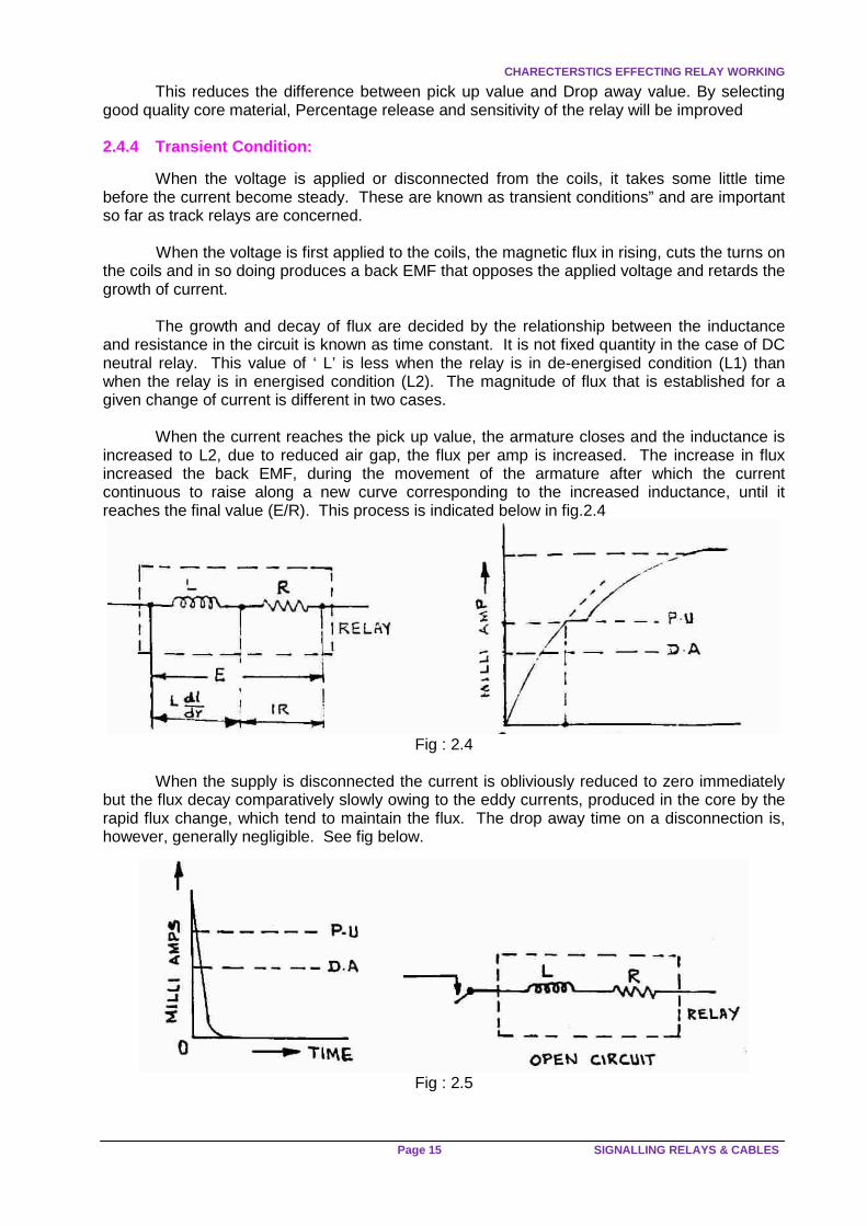
When the voltage is applied or disconnected from the coils, it takes some little time before the current become steady. These are known as transient conditions” and are important so far as track relays are concerned. When the voltage is first applied to the coils, the magnetic flux in rising, cuts the turns on the coils and in so doing produces a back EMF that opposes the applied voltage and retards the growth of current.
The growth and decay of flux are decided by the relationship between the inductance and resistance in the circuit is known as time constant. It is not fixed quantity in the case of DC neutral relay. This value of ‘ L’ is less when the relay is in de-energised condition (L1) than when the relay is in energised condition (L2). The magnitude of flux that is established for a given change of current is different in two cases.
When the current reaches the pick up value, the armature closes and the inductance is increased to L2, due to reduced air gap, the flux per amp is increased. The increase in flux increased the back EMF, during the movement of the armature after which the current continuous to raise along a new curve corresponding to the increased inductance, until it reaches the final value (E/R). This process is indicated below in fig.2.4
Fig : 2.4
When the supply is disconnected the current is obliviously reduced to zero immediately
but the flux decay comparatively slowly owing to the eddy currents, produced in the core by the rapid flux change, which tend to maintain the flux. The drop away time on a disconnection is, however, generally negligible. See fig below.
Fig : 2.5

SIGNALLING RELAYS
IRISET Page16
If the relay releases due to the reduction in current from say I 2 to I 1, caused by the application of shunt resistance (as in the case of track relay ), the time taken is much longer than the relay is simply disconnected.
The rate of rise or fall of current during the transient conditions is also depends on
exterior circuit values because L and R apply to the whole circuit.
The production of eddy current in the core, the flux will decay at a slower rate than the current. So that the actual release time will be a little longer than it takes the current to fall to the release. T ∝ L / R, where T= time constant L= Inductance R= Resistance
Fig : 2.6
It is now clear that to reduce releasing time to a minimum it is necessary that
- The relay iron should have low Hysterisis loss and low retentivity. - The degree of over energization of the relay should be restricted - Connecting a suitable external resistance in series with the relay to keep L/R
ratio low. In non RE area for track circuit length less than 100M 9 ohm track relay only to be used
Using relay with minimum contacts, as they require lesser current which keeps inductance value low
Train working safety is ensured only if the track relay of shortest length track circuit is
released before a light engine running at a highest permitted speed clears it. Otherwise, the track circuit occupation may go undetected. To avoid this, a special provision has to be made in signal control circuits, wherever necessary. The following methods may be adopted for reducing the time lag of track relay.
(a) Restrict the over energisation of relay since the release time depends on the initial
working current. (b) Connecting a suitable external resistance in series with the relay to keep the L/R
ratio low. (c) Using relays with minimum contacts, as they require lesser operating current,
keeping the inductance value low.

REVIEW QUESTIONS
Page 17 SIGNALLING RELAYS & CABLES
Review Questions
Subjective
1) What is the classification of relays on the basis of mounting or fixer ? 2) Explain briefly difference between proved type and non proved type relays 3) What are the main characteristics of electromagnet relays? 4) Explain the working of DC neutral relay.
Objective
1) In any electro-magnetic system, the force of attraction is given by. ---------- 2) Relays, which are loosely kept on shelves are called ------------------------- 3) Track relays : Relay, which is directly connected to the -------------------- 4) The relay iron should have high ------------ and low --------------- 5) T ∝ L / R, where
T = --------- L = --------------- R = ----------

SHELF TYPE DC LINE&TRACK RELAYS
IRISET Page18
CHAPTER 3: SHELF TYPE DC LINE & TRACK RELAYS.
1. ELECTRO-MAGNET 2. RESIDUAL PIN 3. ARMATURE 4. ARM SPRING 5. FRONT CONTACT 6. BACK CONTACT 7. CONTACT CHAMBER 8. CONTACT TERMINALS 9. COIL TERMINALS 10. YOKE Fig No: 3.1 3.1 COMPONENTS 1) Electro-magnet: It has a pair of coils and cores each. Core are joined at the top by a yoke or back strap. Coil terminals can be connected externally to make their series or parallel combination on an insulated block at the top.
The pole faces of the cores are fixed below inside the contact chamber while the contact terminals called "binding posts" extend above on top of the chamber. 2) Armature: A flat piece of iron called "armature" is hinged at the rear on its bracket on two bush type bearings that allow an upward movement for it at the front when the magnet is energized. 3) Residual Pins: The armature has on it two copper or brass pins facing the magnet poles to maintain a small air-gap in its attracted position.

COMPONENTS OF DC NEUTRAL RELAY
Page 19 SIGNALLING RELAYS & CABLES
4) Arm Springs: The armature caries on an insulated block a maximum of six arm contact springs made of phosphor bronze with a fork - shaped front. These springs close with front contacts when the armature is picked up and they close with back contacts when it is dropped. They have silver elements at their tips. 5) Front Contacts: These have Silver Impregnated Graphite (SIG) element. A contact, which is made when the relay is in energized condition. 6) Back Contacts: These have silver elements. A contact, which is made when the relay is in De-energized condition. 7) Contact chamber: This is a glass-walled enclosure for all the contacts and armature.
When the electro magnet coil is energized, a tractive torque acts on the armature below to raise it. The arm springs fixed on the armature are lifted thus, to open back contacts and close front contacts.
When the feed on the coils is removed or reduced, the armature drops due to the gravitational pull downwards, thus opening the front contacts and closing the back contacts.
The line relays have to be according to the IRS Specification No.S53-1988 (Draft). The track relays have to be according to the IRS specification No. S54-1988 (Draft). Most of the requirements in these two specification documents are similar to those in British standard specification No.1659-1950. The important requirements of these specifications are given below. Before studying these, it will be useful to understand certain definitions of terms connected with these relays, given in the specifications. 1. Non-fusible contacts: A pair of contacts in which one contact element comprises of non-fusible material, which presents practically no risk of welding of contacts. 2. Carbon contacts: 'carbon' in the expression 'carbon - to- metal contacts' is used as a general term covering graphite’s and compounds and mixtures of carbon and metals. 3. Metal contacts: 'Metal' in the expression 'metal to metal contacts' is used as a general term covering the use of silver, silver cadmium oxide, tungsten, platinum or any other suitable material to an approved specification. 4. Front contact: That contact which is made with 'arm contact' when the relay is energized. 5. Back contact: That contact which is made with 'arm contact' when the relay is de-energized. 6. Arm contact (or armature contact): That contact which is movable part of the pair of contacts and is made with front contacts when the relay is energized and with back contact when the relay is de-energized. 7. Arm: The movable part of the pair of contacts. 8. Dependent contact: The condition in which a movable arm contact connects to a front contact when the relay is energized and the same arm contact connects to a back contact when the relay is de-energized. 9. Independent contact: The condition in which the movable arm contact connects to either a front or a back contact but not to both. 10. Contact element: Contact piece, which is secured to a contact spring.

SHELF TYPE DC LINE&TRACK RELAYS
IRISET Page20
11. Wiping (self-cleaning) contacts: Contacts designed to have certain relative motion, during the interval from the instant of touching until completion of the crossing motion. 12. Contact follow: That distance which the movable arm contact travels after touching the front or back contact. 13. Contact bounce: means the uncontrolled making and breaking of the contact after it has closed first. 14. Operate: That condition of the relay when all front contacts are just made. 15. Full operate: That condition of the relay when the armature has completed its maximum travel, i.e. up to the stop. 16. Release: That condition of the relay when all front contacts have just opened. 17. Full release: That condition of the relay when the armature comes back up to the back stop. 18. Pick up value: The value of the current or ampereturns which is just sufficient to close all the front contacts of a relay under specified conditions. 19.Drop away (release) value: The value of current or ampere turns at which all the front contacts of a relay just open. 20. Full operate value: The minimum value of current or ampereturns sufficient to energize the relay to the 'full operate' position. 21. Reverse pick up value: The value of current or ampereturns fed in the non-working direction at which all the front contacts are made under specified conditions. 22. Operate Time (of): (a) Back Contact: Means the time interval from the instant of application of the current to the coil until breaking of the back contact, which is the last to break. (b) Front contact: Means time interval from the instant of application of the current to the coil until closing of the front contact which is the last to close and the contact bounce has ceased. 23. Release Time (of). (a) Front Contact: Means the time interval from the instant of removal of energy to the coil until breaking of the front contact, which is the last to break. (b) Back contact: Means the time interval from the instant of removal of the energy to the coil until closing of the back contact which is the last to close and the contact bounce has ceased. 24. Transfer Time:
(a) Transfer time of operate is the interval of time from the instant first back contact breaks until the last front contacts is closed and the contact bounce has ceased.
(b) Transfer time of release is the interval of time from the instant first front contact
breaks until the last back contact is closed and the contact bounce has ceased.

IMPORTANT SPECIFICATIONS OF RELAYS
Page 21 SIGNALLING RELAYS & CABLES
3.2 Common requirements specified in IRS specificat ions (S53 & 54) for shelf type DC line and Track Relays & B.S. Spec. 1659.
1. To avoid damage to contacts during transportation, storage and installation, the relay shall be provided with a transport screw. This shall be designed to keep the armature locked in the 'full release' position. The user shall remove the transport screw and fit a plug-screw in its place. He shall seal it before the relay is used in a circuit. (As per BS spec. 1659 -50). The maximum overall dimensions of the relay shall be
250mm (Height) X 200mm (width) X 200mm (depth).
Minimum insulation resistance of the coil shall be
50 M ohms in dry condition and 10 M ohms in humid condition.
Contact elements shall be
'Carbon’ - for fixed front contacts
Metal' - for fixed back contacts, & Movable arm contact.
Maximum permitted resistance of
Front Contacts: 0.2ohms (When carrying 100mA DC)
(0.18 ohms as per BS.Spec. 1659-50). Back Contacts:
0.05 ohms initially and
0.10 ohms through out life. 0.03 ohms initially
Minimum front contact pressure 14 grams at 125% of PU current in coils. 28 grams at 150% of PU current in coils.
Minimum Back contact pressure 15 grams when the relay is in full release position.
3.3 Comparative Statement of other requirements as in IRS specifications for Line
Relays and Track Relays of shelf type. S.No Feature Line Relay Track Relay 1
Working Voltage
Normal 12V D.C
Minimum: 125% of Relay P.U.V. Maximum: 250% of Relay P.U.V.
2
Coil Resistance
Two coils of 500 Ω +10% Two coils of each (to be connected in series or parallel as required.)
4.5 Ω + 5% two coils of each (to be connected in series or parallel as required.)
3 Standard contact arrangements
2F/B, 4F/B and 6F/B (all dependent)
2F/B and 2F, 2F/B for Non-ACI relay. 2F.2F/B and 4F/B for ACI Relays.

SHELF TYPE DC LINE&TRACK RELAYS
IRISET Page22
S.No Feature Line Relay Track Re lay 4 Contact current
ratings: (a)Continuous
for front contacts
(b)For 30 sec. Through front contact
(c)Continuous for back contacts
(d)Non-inductive DC current breaking capacity of contacts
(e)Inductive load breaking capacity of contacts
3A 5A 3A Max Circuit Current
Voltage No. of operations/ minute
0.6 A 1.5A 5.0A.
12.5V 125V 50V
10 to 20 1 to 2 1 to 2
Current drawn by 3 parallel connected relays of this type.
3A 5A 3A Max Circuit Current
Voltage No. of operations/ minute
0.6 A 5.0A.
125V 50V
10 to 20 1 to 2
Current drawn by one line relay of shelf type
5 Initial pick up current for new relay in mA
(6 to 7.5 mA for 4F/B relays)
Coil Res.
2 or 4Arms 6 Arms Min. Max Min. Max.
250Ω 1000Ω
12 6
15 7.5
15 7.5
18 9
(n) For Non-ACI relays
(37 to 39 mA for 9Ω relay & 74 to 78 mA for 2.25Ω relay) (b) For ACI Relays, Only 9 Ω Relay is allowed. 2F.2F/B or 4F/B contacts Min. Max. 68 72
Coil Res.
2F/B 2F.2F/B Min. Ma
x Min.
M ax.
2.25Ω 1000Ω
74 37
78 39
78 39
8341
6 Initial pick up voltage for new relay in Volts.
Coil Res.
2 or 4Arms 6 Arms Min. Max Min. Max.
250Ω 1000Ω
2.70 5.40
4.13 8.25
3.38 6.75
4.95 9.90
(a) For Non-ACI relays
(b) For ACI Relays, Only 9 Re is allowed 2F.2F/B or 4F/B contacts Min. Max. 0.58 0.68
Coil Res.
2F/B 2F.2F/BMin. Max Min.
2.25Ω 9.0Ω
0.158 0.316
0.184 0.368
0.167 0.333

IMPORTANT SPECIFICATIONS OF RELAYS
Page 23 SIGNALLING RELAYS & CABLES
S.No Feature Line R elay Track Relay 7. Minimum
percentage release.
50% (as per B.S. spec 1659-50 it is 50% for class 'B' relays & 60% for class 'A' relays).
68%
8. Maximum operate time for front contacts.
450 ms. for non ACI relays 500 ms for ACI relays.
500 ms for non-ACI 550 ms for ACI relays.
9. Max. release time for front contacts
100ms for non ACI relays. 125ms for ACI Relays
60ms for ACI relays. 120ms for ACI relays.
10. Max. operate transfer time for front contacts.
400ms 200ms for non-ACI relays 300ms for ACI relays.
11. Permissible max. rise in P.U current from initial value.
10% 10%
12. Permissible maximum decrease in DA current from initial value.
15% 15%
13 Permissible max. change in percentage release.
20% 10% (% Rel. not to fall below 68%).
14. Maximum reverse pick up current
110% of PU current (in the working direction)
110% of PU current (in the working direction.).
15. AC Immunity of relay.
300V(achieved intrinsically without using any external means).
50V(achieved by the provision of copper sleeves and magnetic shunt
3.4 Comparison of Line relay & Track relay S. No Track Relay Line Relay
1. These are connected to the rails directly to detect track occupation
These are connected in different circuits through necessary controls (not connected to rails directly)
2. These works on the principle of reduction in control current changing their position.
These works on the Principle of current or no current controlling their change of position
3. These are necessarily more sensitive.
These are not highly sensitive
4. These carry less number of contacts due to low power operation
These can have more contacts due to sufficient power application
5. POH is 10-12 years POH is 15 years 6. It works on low voltage i.e. less
than 1.00 volts DC It works on high voltage minimum 12 volts DC

SHELF TYPE DC LINE&TRACK RELAYS
IRISET Page24
3.5 SHELF TYPE A.C. IMMUNISED D.C. NEUTRAL RELAYS:- A.C.Immunity of a DC Line Relay is indicated by the value of AC voltage when applied abruptly to a de-energized relay that breaks any of its back contacts. AC Immunity of a DC Track Relay is indicated by the value of AC voltage which when superimposed on normal DC working voltage causes a change of more than a prescribed limit in the relay pickup current. 3.6 Operating and other characteristics of AC immun ised DC line Relays of shelf type.
(Ref. IRS. spec. S60-1978)
(a) The relay shall not make any of its front contacts as a result of 1000V AC (r.m.s) 50Hz sinusoidal voltage when applied gradually at any instant to the terminals of the coil(s) of the de-energized relay.
(b) The relay shall not make any of its front contacts as a result of 750V AC (r.m.s) 1-
phase 50Hz sinusoidal AC voltage when applied abruptly at any instant to the terminals of the coil(s) of the de-energized relay.
(c) The relay shall not break any of its back contacts as a result of 300V AC (r.m.s) 1-
phase 50Hz sinusoidal AC voltage when applied to the terminals of the coil(s) of the de-energized relay . (I) gradually, (ii) abruptly at any instant.
(d) When 100V 50Hz AC voltage is applied continuously to relay coil(s) for 30 minutes,
the heat generated in the coils shall not damage the insulation of the coils.
3.7 Operating and other characteristics of AC immun ised DC Track Relays of Shelf
type.
(a) Determination of DC characteristics under AC influence:-
(i) Maximum 50Hz AC voltage superimposed on normal DC working voltage, without causing a change of more than + 7% in the pickup current shall not be less than 50V.
(ii) Maximum 50Hz AC voltage superimposed on normal DC working without
causing a decrease in the minimum specified percentage release shall not be less than 50V.
(iii) Maximum 50Hz AC voltage superimposed on maximum DC pickup current +
10% causing the armature contacts to move from compressed position shall not be less than 85V.
(b) Non-energisation of the relay under AC influence:-
(i) The relay shall not get energized with abrupt application of up to 350V 50Hz AC
to its coil. (ii) The relay shall not get energized with gradual application of up to 500V 50Hz AC
to its coil. (iii) Permanent application of up to 100 Volt AC to the relay coil shall not cause
injurious heating to it.

AC IMMUNISATION OF DC NEUTRAL RELAY
Page 25 SIGNALLING RELAYS & CABLES
3.8 Timing Characteristics:
(a) Minimum total pick up time when the relay is fed with 10% above the max. Specified pickup current shall not be more than 1 second.
(b) Maximum picks up transfer time, when the relay is fed with 10% above the max.
Specified pick up current, shall not be more than 300 m/sec.
(c) Minimum total pick up time, when the relay is fed with 2.5 times the maximum specified pick up current, shall not be less than 250 m/sec.
(d) Maximum drop away transfer time when the relay is fed with 2.5 times the max.
Specified pick up current shall not be more than 200m/sec. 3.9 INTERNAL PROVISIONS OF SHELF TYPE AC. IMMUNISED DC NEUTRAL RELAY
In this relay (I) two copper slugs on the core near pole faces and (ii) a magnetic shunt above them are provided for immunization purpose.
Fig: 3.2
When A/C current passes through the relay coil. A part of the flux set up in the core say (Ø1), passes through the magnetic shunt. The remaining flux, say (Ø2), is set up through the air gap and armature which links with the copper slugs causing, induced currents in them. The directions of Ø1, Ø2 & Ø3 shown are instantaneous.
The induced currents set up their own flux in opposite direction to (Ø2) through the armature, say (Ø3). This almost neutralizes the operating flux (Ø2). Thus the copper slugs and the magnetic shunt make the relay inoperative for AC. supply.
When DC current passes through the coil, the opposition to the build up of flux through the armature is momentary (transient), which is during the rise of current to its full value. Once the coil current and flux are established, the currents in the slugs cease to flow and the armature remains in the attracted position. This arrangement, however, requires more operating power and delays operation.
Similarly, when the coil current is falling, the slug currents oppose the decay of flux through the core. This results in a delayed release of the armature.

SHELF TYPE DC LINE & TRACK RELAYS
IRISET Page26
Fig: 3. 3
When a certain AC current is superimposed on the DC working current, the alternating flux shows a tendency to destabilize the DC flux, which lifts or holds the armature. Hence the DC pickup value of the relay increases. This increase may cross the limits beyond a permitted minimum value for AC interference, i.e., 50V for this relay.
The fluxes set up in the core by the DC and AC currents before the relay operation are shown in the fig. In this case also, the pick up and release of the relay gets delayed till the reactive current flux is setup by the slugs in the core.
Review Questions
Subjective 1) What are the parts of shelf type relays? 2) Draw the figure of shelf type relay. 3) Explain how the AC immunity is achieved in AC immunized DC neutral shelf type relay? 4) What is the purpose of residual pin? 5) Compare the line relay and track relay Objective 1) The armature has on it copper or brass pin facing the magnet poles to maintain a small
air-gap in its attracted position is called ----------- 2) Working voltage of line relay is ------------ 3) Working voltage of t rack relay is ------------ 4) Coil resistance of line relays is ----------- 5) Coil resistance of t rack relays is -----------

QN1 RELAY
Page 27 SIGNALLING RELAYS & CABLES
CHAPTER 4: PLUG IN TYPE DC NEUTRAL LINE RELAYS (NON-PROVED TYPE)
4.1 Two styles made in this type to BR specifications are introduced on Indian railways, P-series / Q-series relays. They are called because their name code starts with these letters. However, P-series relays are going out of use gradually. Q series relays are now universally used with the British signalling practice. Even as no separate IRS specifications are issued for these relays, they confirm to IRS specification No S23 and S34 (for testing procedures) broadly.
4.2 Plug in DC Neutral Relays of Non-Proved Type (Q -series relays) The basic constructional features of these relays are as follows:
(a) Standard plug board common to all relays. (b) Plug-sockets kind of interconnection between plug board and relay. (c) A retaining clip provided to hold the relay firmly in the plug board, so that there is no
possibility of loose electrical connections. (d) Connectors, which are positively locked in to the plug board and can be with drawn
by a special tool to permit easy disconnection. (e) Means for terminating permanent wiring to plug board on the connectors both by
crimping & soldering. (f) Registration device with specified coding combination in order to prevent a wrong
relay being plugged. (g) No electrical connection possible between plug board and the relay base until code
pins have correctly engaged. (h) Fixed contact positioned by adjustment cards and moving contact positioned by
operating arm driven by the armature. (i) Provision of helical spring to provide definite back contact pressure and aid in return
torque. (j) Provided with Non-proved (metal to carbon contacts) and all are independent
contacts only.
4.3 DC Neutral line Relay -- Style QN1
The fundamental relay of the Q-series is the DC neutral line relay style QN1. All other relays of the Q series have been developed around the QN1 in an effect to standardize the components.
The iron circuits and the contact stacks are mounted on a molded base of extremely stable thermosetting material. Up to four contact stacks are fixed to the base, each with four independent contacts.
The iron circuit is mounted below the contact stacks. It consists of an ‘L’ shaped heel piece, core with bobbin and an armature. The armature pivots on a phosphor bronze pivot plate, which is riveted to the heel piece.
The contact springs are made of phosphor bronze. The fixed contacts are positioned by adjustment cards located on the brackets riveted to the heel piece, while the moving contacts are positioned by operating arms driven from the armature. All movable arm contacts are silver (sil) and fixed front and back contacts are silver impregnated graphite (Sig)
The relay is provided with a handle attached to molding base of the relay. A transparent cover covers all the components.
The rated life of relay shall be taken as 1000000 cycles under specified conditions of
operation where one cycle consists of an operation followed by a release.
PLUG IN TYPE DC NEUTRAL LINE RELAYS (NON-PROVED TYP E)
IRISET Page28
RELAY CONSTRUCTION:
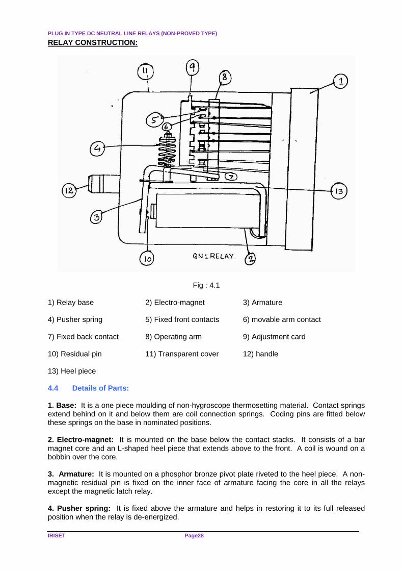
Fig : 4.1 1) Relay base 2) Electro-magnet 3) Armature 4) Pusher spring 5) Fixed front contacts 6) movable arm contact 7) Fixed back contact 8) Operating arm 9) Adjustment card 10) Residual pin 11) Transparent cover 12) handle 13) Heel piece 4.4 Details of Parts: 1. Base: It is a one piece moulding of non-hygroscope thermosetting material. Contact springs extend behind on it and below them are coil connection springs. Coding pins are fitted below these springs on the base in nominated positions. 2. Electro-magnet: It is mounted on the base below the contact stacks. It consists of a bar magnet core and an L-shaped heel piece that extends above to the front. A coil is wound on a bobbin over the core. 3. Armature: It is mounted on a phosphor bronze pivot plate riveted to the heel piece. A non-magnetic residual pin is fixed on the inner face of armature facing the core in all the relays except the magnetic latch relay. 4. Pusher spring: It is fixed above the armature and helps in restoring it to its full released position when the relay is de-energized.

PLUG BOARD
Page 29 SIGNALLING RELAYS & CABLES
5. Contacts: The fixed front and back contact springs are held in position by adjustment cards located on a bracket riveted to the heel piece. These springs are preset against their stops on the adjustment cards so that equal pressure is obtained on all the contacts during their making. Contact wear during the life of relay has little affect on the contact pressure. Operating arms each held between the armature and a holding spring on top of the contact stacks drives the moving arm springs. All the front and back contacts of these relays are independent 'carbon-to-metal' contacts except the heat-operated contacts of Time element relays. This ensures their non-fusibility. 6. A transparent cover : A transparent cover covers all the components. 7. A handle : a handle attached to moulding base of the relay. 8. A retaining clip : It is hooked onto the plug board over the relay and holds them tight together.
While an exhaustive data sheet is given at the end of this chapter with details of all the relays in common use, a brief account of the salient features of each relay is given below: 4.5. Plug Board (Back view)
Fig: 4.2
It is a one piece moulding of the same material as the relay base. It is provided with
slots (sockets) for accommodating wire connectors and a relay. It is provided with 4 columns and each column is provided with 8 No of slots, i.e. for 4 numbers of contacts. Maximum 16 numbers of independent contacts are available in ‘Q -series relay and for relay coil connections 4 slots are provided, there by two numbers of coils can be terminated.
Removable connectors are provided with both soldered and crimped. Connectors can be removed only with a special tool.
Q- Series neutral line relays are provided with 16 numbers of independent contacts. In this some of the contacts are fixed front / back contacts, which cannot be changed, and some are the interchangeable contacts. These contacts can be interchanged. The changing of contacts can be done by the manufacturers at their manufacturing unit. The manufacturers seal the relay, users are not allowed to open the relay.

PLUG IN TYPE DC NEUTRAL LINE RELAYS (NON-PROVED TYP E)
IRISET Page30
A1 B1 C1 D1 A2 B2 C2 D2 (a) Fixed Front contacts (08 No.s) A3 B3 C3 D3 A4 B4 C4 D4
A5 D5 A6 D6 (b) Fixed back contacts (04 No.s) A7 D7 A8 D8 (c) Interchangeable contacts (04 No.s) 4.6 Registration Device (Coding pins / Sockets)
Fig: 4.3 FRONT VIEW OF PLUG BOARD
Each relay is provided with code pins, which prevent a relay being plugged in to wrong
plug board. Pin position coding is provided for plug-in type relays. This ensures that a front contact does not get connected to the circuit wiring of a back contact or a back contact does not get connected to the wiring of a front contact in the base, which may cause unsafe conditions. There are 10 (ten) positions for code pins in the relay base with corresponding socket positions in the plug board as shown in the figure above.
B5 C5 B6 C6 B7 C7 B8 C8

CONTACT ARRANGEMENTS
Page 31 SIGNALLING RELAYS & CABLES
The base of a Q- series relay is plugged in to a vertically mounted plug board on the rack, with a matching “code pins and sockets” arrangement between them. Any five of the ten positions are drilled in the plug board and five pins are fitted to the relay base in the corresponding positions. This gives 252 unique arrangements. All these arrangements are numbered serially as 001, 002 …….252.These are known as code numbers. Relay of the same type having different contact arrangements will have different code numbers Six (6) more code pin positions are used for special relays.
It may be seen that relays of different contact arrangements having identical positions for front and back contacts, have the same code numbers. 4.7 Contact Arrangements: ‘Q’- Series relays are provided with a maximum of 16 independent contacts, and the standard contact configurations are:
(a) Line relays: -- 12F / 4B, 8F / 8B, 8F / 4B, 6F / 6B, 6F/ 2B, 4F / 4B etc
(b) Track relay: -- 2 F /1B, 2F / 2B.
(c) ECRs : -- 3F / 3B , 4F /4B etc. Rear view of a plug board of line relay

PLUG IN TYPE DC NEUTRAL LINE RELAYS (NON-PROVED TYP E)
IRISET Page32
4.8 Deference between shelf type and plug in type r elays:
Shelf Type
Plug in Type
Heavy and large Light and Compact. Takes more space. Less space. Replacement takes time Replacement is quicker. As wiring gets disturbed during replacement, circuit has to be tested again.
Not Necessary as no wiring is disturbed
No coding arrangement required. Coding arrangement is provided for safety.
More sensitive as they have large magnets. Less sensitive. Lesser voltage of operation. More voltage of operation. Periodical overhauling to be done.
a) Line relay- 15 years b) Track relay-10-12 years
No periodic over hauling for a line relay. Track relay to be replaced after 10 years.
Both independent and dependent contacts are available
Only independent contacts are available
Maximum 6 dependant contacts are available
More number of contacts are available i.e. 16 No.s
4.9 Types of Q Series Relays 4.9.1 QN1: DC Neutral Line relay: (Spec: BRS 930A)
Fig: 4.5 QN1 RELAY
All combinations: 12F/4B, 8F/8B, 8F/4B, 6F/6B, and 4F/4B). Working voltage: 24V, (50V as track relay for ABB AFTC). Coil resistance: 400 Ohms for 24V relays. Operating current: 60mA. Max P.U is 19.2 V, Min. DA is: 3.6V.
P.U time: 150m seconds, DA time: 20m seconds. Application: All control and detection circuits of Non R/E area and Internal Circuits in R/E area.

TYPES OF ‘Q’ SERIES RELAYS
Page 33 SIGNALLING RELAYS & CABLES
4.9.2 QNN1: DC Twin Neutral Line Relay . (Spec: BRS 960)
Two neutral relays with common heel piece, common base. Both relays are independent of each other and can be used for two different circuits. (Unrelated) Contact combination: 6F/2B, 4F/4B each.
(Both relays will have same contact combination). Coil Resistance: 470 ohms Normal working voltage: 24v Max PU: 19.2V, Min DA: 3.6V. Application: All circuits of Non RE and Internal circuits of RE. Saving of space and used in circuits needing less number of contacts. They have equal number of contacts on both the relays. 4.9.3 QNA1: AC immunized DC Neutral Line Relay. (S pec: BR 931A)
QNA1 RELAY Fig : 4.6
AC immunity requirements of (IRS S 60-78), the relevant provision of which are given below:
(a) No front contact to make by sudden application of 1000 V 50Hz AC.
(b) Relay not to break its back contact when 300Vrms is applied gradually or abruptly.
(c) Maximum P.U transfer and release transfer time not more than 200 m Seconds when relays energized with 80% rated voltage.
A/C Immunisation is achieved by the provision of copper slug at the armature end of the
core. No magnetic shunt is used. A/C immunisation principle is same as in the case of shelf type relay. In all other aspects it is same as QN1.
AC immunity level: 120V AC (r.m.s) 1-phase 50 Hz
Voltage: 24VDC. PU time: 220ms, DA time: 70ms.
Application: All external control and detection circuits in railway electrification.

PLUG IN TYPE DC NEUTRAL LINE RELAYS (NON-PROVED TYP E)
IRISET Page34
4.9.4 QS3: Q series sensitive neutral relay (Spec BRS 930A)
This is a sensitive line relay designed to work on low voltage and current in a manner similar to shelf type neutral line relay. It is intended to replace shelf type line relay. This is made to work on 12V DC Working voltage : 12V DC Coil resistance : 1000 ohms Contact configuration : 4F/4B contacts Operating current : 12mA. Max: PU voltage : 9.35V, Min PU voltage : 7.5V, Min DA voltage : 3.75V
This relay is classified as ‘A’ class relay and % release is more than 60 %.
Designed originally to replace shelf type 1000 ohms line relays in axle counters, i.e. evaluator relay and supervisory relay (EVR, SUPR)
QSA3: Q Series sensitive AC immunized dc neutral relay. (12V,1000 ohms, 4F/4B). 4.9.5 QB3: DC biased Neutral Line relay (Non AC Im munized)
Fig: 4.7
This is a DC biased neutral line relay. It operates only when rated DC supply of correct polarity is connected. The armature does not get attracted for reverse polarity supply of 20 times the rated 12V DC (i.e. 240 V DC)
Biasing of the relay is achieved by the provision of a permanent magnet, which aids the
Electromagnet flux. Permanent magnet need not be powerful, as ‘armature’ need not to be held in attracted position by its flux alone. Neither the electro-magnetic coil flux nor the Permanent Magnetic flux can hold the armature in attracted position on their own. Armature gets attracted only when both fluxes are acting in the same direction. Advantage of biasing is that two relays can be connected on the same line. Hence a pair of conductors can be saved. It is used in Podanur make single line token less push button type block instruments as code receiving relays CRR(R) and CRR(N).
Rated voltage : 12 VDC and current: 60 mA Standard contact : 4F/2B. PU current : 45 mA. PU Time : 380 ms DA Time : 20ms

QBA1 RELAYS
Page 35 SIGNALLING RELAYS & CABLES
4.9.6 QBA1 : Biased AC Immunized DC Neutral Line Relay . Spec: BRS 932A.
Fig: 4.8
This is a DC biased AC Immunized neutral line relay. It operates when rated DC voltage of correct polarity is connected. It does not get attracted for 20 times the rated 24 VDC in reverse polarity. To make the relay AC Immunized Copper slug is provided at its armature end and biasing feature is achieved by providing a permanent magnet adjacent to copper slug. This relay is used in “DAIDO” Single line Block Instrument, used in RE area.
Coil resistance : 200 Ohms coil. Working voltage : 24V DC. Contact combinations : 12F/4B, 8F/4B, and 8F/8B. AC immunity level : 120 VAC as per BRS931. (87 SSG meeting tested immunity with
500volts) Contact current rating: 3A (continuous) and 2A (Switching). 4.9.7 QBCA1 Relay made to BR specn.No.943
(Q series biased A/C immunized relay with heavy dut y front contact)
This is a relay similar in construction to QBA1 relay. But it has two heavy duty front contacts and four back contacts of standard current rating. The front contacts can carry and switch up to 30A inductive current at 110 VDC.
Fig: 4.9 A
These relays are used for point machine control of both high voltage type (110 VDC) and low voltage type (24 VDC) In this relay, two natural magnet pieces called "Blow Out” magnets are fixed on a

PLUG IN TYPE DC NEUTRAL LINE RELAYS (NON-PROVED TYP E)
IRISET Page36
bracket by the side of front contact elements. Spark quenching by these magnets during operation makes it possible for them to switch heavy currents. Two extension springs each behind the base are joined with front contacts and their arm springs so that two wires can be connected for sharing the heavy current through these contacts. Point motor feeding through these contacts shall be as given below:-
Fig : 4.9 B
Note: For correct operation of heavy-duty contacts, polarities shown above must be observed correctly. The wires recommended for use with these contacts are 9/0.012" copper conductors. Current to the back contacts can be carried by 16/0.2mm dia. wires like in the case of any other Q-series relay contacts. The relay is immune to the affects of 1000V AC 50Hz in the de-energised condition. However, it is usually tested with 120V 50Hz abrupt application for AC immunity. The minimum pressure specified for the front contacts of this relay is 56 gms, whereas it is only 28gm for the c-to-m contacts of other relays of this series.
QSPA1: Q series Slow to pick up AC immunized DC neu tral relay (Spec. BRS 933A)
Fig: 4.10 A Magnetic shunt is provided at the armature end to make the relay slow to pick up.
Magnetic shunt is of a magnetic material, when the current flows through the coil it set up a flux which passes through the magnetic shunt, after a time delay the magnetic shunt saturates, further flux will not flow through the magnetic shunt. Then magnetic circuit completes through core, air gap, armature and heel piece there by armature get attracted after a time delay of 540-600 m seconds. Hence this relay becomes suitable to used as TPR for Q series TRs.

QSRA1 RELAYS
Page 37 SIGNALLING RELAYS & CABLES
To make the relay AC Immunized, Copper slug is provided at the heel piece end.
Used as TPR where Q-series AC immunized track relays are provided. OHE Circuit Breaker tripping may take around 300 m seconds after catenary’s snapping/short circuiting of OHE supply. This causes high voltage drop across the track, which may operate the Track relay. But it is essential that the repeater should not pick up. Hence slow to pick repeater relay is used. Pick up time for relays used as repeating relays with plug in type AC immunized track relays shall have a pick up time of at least 400 m seconds. Pick up time : 540-600 m seconds. Release time : 140-200 m seconds. Working voltage : 24 V DC Coil resistance : 208 ohms Contact configuration : 8F / 4B A/C Immunity level : 300 V AC 4.9.9 QSRA1: Slow to release AC immunized DC Neutr al Relay ( BRS Spec. No. 934A)
Fig: 4.11 Magnetic shunt is provided at the heel piece end to make the relay slow to release. Copper slug is provided for AC immunization. DA time : 260ms. Working voltage : 24 V DC Coil resistance : 208 ohms Contact configuration: 8F/4B A/C Immunity level : 300V AC Used as HPR, DPR in RE area. Insensitive to momentary track circuit bobbing and power supply fluctuations.

PLUG IN TYPE DC NEUTRAL LINE RELAYS (NON-PROVED TYP E)
IRISET Page38
4.9.10 QL1: Q – Series Magnetic Latch Relay (BRS S pec. No. 935A)
Fig : 4.12
Relay latches magnetically in the operated position. This is achieved by the use of a permanent magnet, provided at the heel piece end. Note: The difference in the position of the Permanent magnet i.e. in biased relays the Permanent Magnet is at armature end and for latch relays it is placed at the heel piece end. There is no residual pin as it is a latched relay and requires power supply for releasing the relay.

REVIEW QUESTIONS
Page 39 SIGNALLING RELAYS & CABLES
This relay contains two coils namely Reverse Coil (Operating coil) (150 ohms as more flux is required for operating) and Normal Coil (Release Coil) (680 Ohms release coil as less flux is required to oppose the flux of permanent magnet causing the armature to release). They wound on the same core in opposite direction to each other.
When pick up coil is energized, flux produced assists Permanent magnetic flux and the armature is attracted to pick up position. The armature is held in this position by the Permanent magnet flux even after P.U coil supply is disconnected. The latched relay feed is cut off as soon as it is latched. The Permanent magnet is a strong magnet, as it is required to hold the armature in the pick up position. Feed to operating coil is cut off externally by using back contact of repeater relay.
When the release coil is energized it produces a flux, which opposes the permanent magnet flux there by force on the armature reduces, the pusher spring pushes the armature to release position. Feed to the release coil is cut off internally (internally wired in series with a front contact and is automatically open circuited during the release cycle). This arrangement is done to avoid prolonged feed to N coil whose flux opposes the PM flux, may demagnetize the Permanent magnet. Working Voltage : 24V. Coil resistance (reverse) :145 ohms (Release) : 680 ohms Contact combinations : 11F/4B, 8F/6B. Application : TCFR, TGTR, TAR and TOLAR in PTJ push button block
instruments.
Review Questions Subjective
1) Draw the contact arrangement for 8F/8B Q series relays. 2) What is the difference between shelf type and plug in type relays 3) Explain the features of QN1 relays 4) Explain the coding arrangement provided in Q series relays 5) Explain the latch relay working in Q series type Objective QL1: Latch relay is used in ---------------- bloc k instruments 1) Q series Latch relay contains two coils namely Reverse Coil (Operating coil) --------- Ohm
and Normal Coil (Release Coil) ---------------- Ohms 2) QSRA1: Slow to release AC immunized DC Neutral Relays are used for --------------- 3) Coil resistance of QSPA1 relay is ------------------ 4) QBCA1 relay heavy duty front contact can carry current of ------------.

PLUG IN TYPE DC NEUTRAL LINE RELAYS (PROVED TYPE)
IRISET Page40
CHAPTER 5: PLUG IN TYPE DC NEUTRAL LINE RELAYS (PROVED TYPE) FOR RAILWAY SIGNALLING
IRS Specification No: S46-76. 5.1 This specification relates to design and performance requirements for DC Neutral Line Relay (proved type) with metal to metal contacts for use in Railway Signalling Circuits. Some of the important points are as under.
GENERAL REQUIREMENTS 3.0 Design and Drawings 3.1.1 The relay shall meet the requirements of this specification for material, design assembly
and finish, etc, in entirely and also relevant requirements in other specifications. 3.1.2 Necessary technical particulars including drawings forming an essential part of an offer
for relay to this specification may be asked to be furnished for examination by the purchaser.
3.2 Mounting and cover 3.2.1 The relay shall be so designed that it can be mounted with in a relay group housing such
that the relay are protected against dust and moisture under service conditions when enclosed in such relay group housing . Alternatively, the relay shall be provided with an individual transparent cover which protects the relay from dust and moisture under service conditions. In either case the relay and its moving parts including contacts shall be clearly visible for inspection from out side.
3.2.2 Sealing arrangement shall be provided for the relay group housing in which the relays
are enclosed for individual cover for the relay where provided, so that there is no possibility of unauthorized interference with the contact arrangement and other moving parts. Locking arrangements may also be provided when required by the purchaser.
3.2.3 The relay housing or cover shall all he free from detrimental warping which may reduce
clearance between the housing or cover and any moving parts of the relay, either from temperature or moisture changes or long term aging or from release of locked up stresses.
3.2.4 The clearance between the cover of relay or group of relays and the moving parts of the
relays shall not be less than3mm. 3.2.5 The cover and base of the relay group housing or individual cover and base—plate of
the relay shall be gasketted in such a manner as to protect the whole against dust, moisture and Vermin.
3.3 Air Clearance Distance 3.3.1 An Air Clearance distance of minimum 1.8 mm. shall be provided between any exposed
current carrying part and any other metallic part insulated there from. However, it is desirable that a clearance of not less than 3 mm wherever possible, is provided.
3.4 Surface Leakage Distance 3.4.1 A surface leakage distance of minimum 1.8 mm. shall be provided between any exposed
metallic part carrying current and any other metallic part insulated there from. However. it is desirable that a surface leakage distance of not less than 3 mm wherever possible.
is provided.

SPECIFICATION FOR PROVED TYPE RELAYS
Page 41 SIGNALLING RELAYS & CABLES
3.5 Other Requirements
3.5.1 These shall be as in Clause 4 of IRS Specification No. S 23*(except sub-clauses 4.4,4.5
and 4.6).
3.5.2 All nuts and screws shall be securely locked and shall not loosen while in service due to
vibration or other causes as normally met with in Railway usage. 3.5.3 Screw threads in parts fabricated of materials which do not lend themselves to
successful tapping shall be formed in bushes made from suitable material, and these bushes shall be properly moulded, embedded or otherwise securely fixed.
4.0 DIMENSIONS 4.1 The overall dimensions of the Relay (with maximum contact equipment) shall not exceed
the, following, unless otherwise approved by the purchaser
WITH OUT COVER WITH COVER
HEIGHT 55 mm 75mm
115mm 135mm (I/L relays when mounted height wise)
WIDTH 42mm 62mm
85mm 105mm (I/L relays when mounted width wise)
DEPTH 120mm 140mm 4.2 Limits and fits shall in general be as per sub-clauses 6.1 and 6.2 of IRS Specification
: No. S 23*, except where specified or required otherwise for proper functioning of the equipment.
4.3 Dimensions on which tolerances are not indicated shall be with in the following limits
depending also on related dimensions for correct functioning, unless otherwise agreed up on by the purchaser.
4.4 Casting and sheet metal parts + 0.50 mm Insulating molding parts As per BS : 2026 Spacing of Machined holes +0.05mm Angular Dimensions + ½ 0 Linear dimensions +0.5mm. Diameter of Drilled holes (Clearance holes)
As per IS :1821 (Fine).
5.0 Workmanship 5.1 The standard of workmanship shall be as per clause 5 of IRS Specification No.S~23*. 6.0 MATERIALS 6.1 Transparent material for relay cover or for use in front of relay group housing shall be
permanently transparent though self extinguishing and non-hygroscopic and shall be unaffected by changes in- temperature between - 25oC and 85o C
6.2 Magnetic materials for Armature and Core etc., shall comply with clauses 10.1 and 10.3 of IRS Specification No s 23.

PLUG IN TYPE DC NEUTRAL LINE RELAYS (PROVED TYPE)
IRISET Page42
6.3 All insulating materials shall be tough and non hygroscopic and shall he unaffected by changes in temperature between -25oC and +850C. Insulating materials used as insulation for contacts and coil bobbin must be self-extinguishing and preferably so for other purposes also as far as possible.
All insulating materials in contact with current carrying parts of the relay shall comply
with the following test. “Two 6 mm diameter electrodes shall be placed 3 mm. Apart on a sample of the material, which is at a temperature of not more than 200C. The sample then shall be transferred to a test chamber having a temperature of 550C and a humidity of 95 per cent. The insulation resistance measured at a voltage of 500 V D. C. Between the electrodes shall not then fall below 1 meg ohm while the samples remain in the test chamber for a period of not less than 15 seconds”.
6.4 Material used for impregnation or insulating the coils shall be chemically neutral and
physically stable between temperature limits of - 250 and 850. 6.5 Insulating material used for filters in winding coils shall be chemically neutral. 6 6 Insulating sealing compound shall not melt, flake or crack between temperature limits of
- 250C and +850C. 6 7 Material for electrical contact springs and contacts shall comply with clause 9 of IRS
Specification No. S 23. Contact springs shall be made either from phosphor bronze material to specification BS 407, Grade PB 102 (Extra hard or hard) or from Nickel Silver with minimum I 8 percent Nickel to Specification BS 790. The contacts shall be made either from fine silver of minimum 99.9 per cent purity to specification IS 2112 or from silver cadmium oxide material (having minimum 10 percent cadmium oxide conforming to an approved specification acceptable to the purchaser.
6.8 Contact keeper, where provided, shall be of the same material as of contact spring, as
far as possible. – 6.9 Other materials employed in the construction of the relays shall allow them to function
perfectly with in a temperature range from - 250C to +850C and shall be in accordance with Specification for ‘Materials’ in the IRS Specification No. S 10 or, other appropriate approved standard specifications, as far as applicable.
6.10 No materials shall be used in the construction of the relay which are capable of
supporting growth of mould or which are subject to deterioration by exposure to sun light or which would cause alteration in performance during storage life or which are not capable of maintaining all their essential electrical and mechanical properties during service life of the relay.
7.0 PROTECTION AGAINST CORROSION. 7.1 Protection against corrosion shall be provided as per clause 13 of IRS Specification No S 23 7.2 Material used for protection against corrosion shall neither melt nor flake under ordinary
conditions between temperature limits of - 250 and +850. 7.3 All parts, both separately and in combination shall either be resistant to corrosion. Dis-
similar metals used in contact with each other shall be so chosen or protected as to minimize the effect of electro - chemical action.

SPECIFICATION FOR PROVED TYPE RELAYS
Page 43 SIGNALLING RELAYS & CABLES
8.0 MAGNETIC SYSTEM 8.1 The core and armature supports shall be so designed as to ensure a reliable operation
of the core with respect to the armature and to the fixed parts at the contacts shall be maintained constant trough out the service life of the relay.
8.2 The armature supports shall be so designed as to ensure a reliable operation of the armature. The movement of the contacts shall be controlled rigidly by the movement of the armature indirect control by other contacts springs or by any other means being dis-allowed. The functioning of the contacts shall be controlled by gravity or combination of gravity and spring action provided that gravity alone must cause the front contacts to open, if the spring action fails, when the relay is de-energized in the normal mounting position of the relay.
8.3 The armature shall be positively located so as to prevent any displacement other than that required for a proper operation of the contacts. End play of the armature when pushed or slide from one end to the other end shall be not less than 0.1 mm and not more than 0.4 mm
8.4 The travel of the armature must be limited by means of stops which shall last for the
‘whole service life of the relay, and which shall not cause any rebounding, with-holding or sticking of the armature. These stops must be made of an anti-residual, anti-corrosive material, and the gap between armature and core must not be affected either by distortion or by wear. With the armature in the picked up position, a minimum physical air gap of 0.3 mm. (0.1 mm. for special relays) shall be provided (at the center of the portions of core and armature coming opposite each other) by a non-adjustable stop suitable dimensions.
8.5 ln relays fitted with knife-edge bearings, the armature shall be held in its place in such a
manner as to permit free movement throughout the normal stroke, but shall prevent its being displaced as a result of Type Tests carried out under Clause 15.2.
8.6 In relays fitted with pivot bearings, the armature pivots and bearings shall be cylindrical and the bearings shall be neither less than 0.05 mm. nor more than 0.1 mm. larger in diameter than the pivots. The armature pivots and bearings shall be of dissimilar materials possessing high resistance to corrosion under service conditions, shall fit rigidly in their supports, and be suitably secured and so constructed that they cannot restrict the desired motion of the armature. The design shall be such that the breaking of a pivot shall not allow any front contact to close irregularly.
9.4 ELECTRO-MAGNET COILS 9.1 Electro-magnet coils shall comply with the requirements as per Clause 8 of IRS
Specification No. S23* (except sub clause 8.2, 8.6, 8.11 and 8.12).
9.2 When electrically separate windings are, provided, each shall be capable of fully, operating the relay and the design shall be such that both windings could remain continuously’ energized simultaneously.
9.3 No conductor of diameter smaller than 0.08 mm. (0.05 mm. For special relays) shall be
used for coil windings, unless otherwise approved by the purchaser. 9.4 Coils shall be such that they shall be able to carry 125% of the rated current
continuously and 150% of the rated current for four hours without injurious heating, at an ambient temperature of 200C+20C.
9.5 The coils shall have leads (preferably flexible) of suitable size, length and strength for
connection to solder lugs / tags of the coil. The insulation of the leads shall remain flexible under all service conditions. The solder hugs/tags of the coil shall be made out of brass sheet silver plated or of same material (Un plated), as of contact spring
9.6 Coil resistance shall not vary from the nominal value by more than +15 % for wires
below 0.08 mm. diameter and +10% for wires of 0.08 mm. dia and above, when measured at200C. This permissible variation in resistance shall have no adverse effect on the performance of the relay as per the specified operating requirements.

PLUG IN TYPE DC NEUTRAL LINE RELAYS (PROVED TYPE)
IRISET Page44
9.7 The purchaser may specify the nominal resistance of the coil. Where it is not so
specified, coil resistance shall be such that the coils comply with specified operating requirements, within a variation up to ±20% from the rated voltage.
9.8 Four contact prongs (solder Lugs/coil tags) must always be provided, being marked RI, R2, R3 and R4. Coil of a single wound relay shall be connected to contact prongs marked R1 and R2 and the coil of the second winding, when provided, would be connected to contact prongs marked R3 and R4; the connection- to be so made that the coils must assist with the like polarities:- on contact prongs marked RI and R3.
9.9 The particulars of the coil it respect of Manufacturers’ Trade Mark, nominal resistance at
2Odeg C, number of turns, size of wire and kind of wire insulation shall be exhibited on a label./tag of non conducting material plainly and indelibly marked which shall be located at a conspicuous position and securely fixed, preferably the first layer of the coil sheathing.
10. CONTACTS 10.1 Contact equipment - 10.1.1 The relay shall be provided with one of the standard contact arrangement as shown
below, except where specified differently by the Purchaser.
Number of Independent Contacts.
Front ... 2 3 4 6 5 4. Back ... 2 3 2 2 3 4. 10.1.2 Contacts shall be ‘metal to metal’. 10.2 contact assemblies: 10.2.1 Contact springs shall be formed in such a way that their main axes lie at not more than
45° from the direction of rolling of the strip and so that abrupt changes of dimensions, giving rise to high-localized stresses do not occur.
10.2.2 The design shall be such that contact springs shall not be subjected to any twist about
their longitudinal axis. 10.2.3 Contact elements shall not be out of center with respect to each other by more than 0.5
mm. (0.02”). 10.2.4 Contact elements shall be firmly secured so that they will not shift or become loose
during transport or service. 10.2.5 The materials used in affixing contact elements shall be such as not to cause corrosion 10.2 6. All similar contacts, i.e. either front or back, shall function approximately simultaneously
when the relay is operated or released. The difference in the voltage- between that at which the first and the last front or, back contacts break shall as far as -possible be within 5% of the maximum full operate voltage. In the alternative the difference in the stroke between that at which the first and the last front or back contacts break shall be within about 10% of the full stroke of the moving contacts/the Contact pins.
10.2.7 If twin contact elements are employed, these shall be co-planar and shall make or break
contact approximately simultaneously. 10.2.8 Contacts when enclosed inside the relay cover shall be readily visible from the front of
the relay. Similarly, the relay contacts shall be visible from the front of the relay group housing.

SPECIFICATION FOR PROVED TYPE RELAYS
Page 45 SIGNALLING RELAYS & CABLES
10.2.9 Contact spring fingers shall be made of such material and so Proportioned that they shall not stress beyond half of their elasticity limit. Movements of contact springs shall ensure self-aligning, self-cleaning and wiping action between the Contacts.
10.2. 10 Contact springs must be in positive contact with their backing springs, when provided. 10.2.11 As far as possible, the opening and closing contacts must not be accompanied by any
rebound exceeding duration of 10 milli-seconds and the contact elements shall establish steady contact conditions after this period when the relay is energized at rated voltage or is released.
10.2.12 When in the normal mounting position a relay must still function perfectly, i.e., a closed
contact must not open and an open contact must not close on their own, whether the relays are energized at 20% in excess of rated voltage or they are not energized, when subjected to sinusoidal vibrations, in which the oscillations have an amplitude of 1 mm. at a frequency between 5 and 50 c/s.
10.3 Contact Clearances - 10.3.1 Minimum clearance between the back contact elements:
(a) When the relay is in operate position - (at the instant at which closure of front -
Contacts occur.
0.5 mm for contacts in series (1.1 mm desirable). 1.0 mm for single contacts . (1.3 mm desirable)
(b) When the relay is in full operate position: - 1.2 mm for contacts in series . (1.8 mm desirable). 2.0 mm for single contacts . (2.5 mm desirable) 10.3.2 Minimum clearance between the front contact elements shall be as under.
(a) While dropping of the moving armature of the relay is taking place (at the instant at which closure of the back contacts occurs)
0.5 mm for contacts in series (1.1 mm desirable) 1.0 mm for single contacts (1.3 mm desirable)
(b) When the relay is in full release position
1.2 mm. for contacts in series (1. 8 mm desirable). 2.0 mm. for single contacts (2 .5 mm desirable).
10.3.3 The values for contact clearances specified in clauses 10.3.1 and 10.3.2 must not vary during the endurance test on the relay to clause 15.2.2(d) 10.4 Contact Pressure 10.4.1 When the armature is in the full operate position, initial contact pressure for front
contacts shall not be less than 15 gms per contact element in the case of single contacts, and 10 grams per contact point in the case of double contacts.
10.4.2 When the armature is in the full release position initial contact pressure for back contacts
shall not be less than 15 gms. Per contact element in the case of single Contacts, and 10 grms per contact point in the case of double contacts.

PLUG IN TYPE DC NEUTRAL LINE RELAYS (PROVED TYPE)
IRISET Page46
10.4.3 The loss in contact pressure through out the endurance test on the relay to clause 15.2.2(d) (both for loaded and un-loaded contacts) shall not exceed 40% of the initial contact pressure.
10.5 Contact Resistance 10.5.1 For “metal to metal’ contacts, initial clean contact resistance shall not exceed 0.05
ohms. 10.5.2 Increase in contact resistance through out the endurance test on the relay to clause
15.2.2(d) shall not exceed 100% of the initial contact resistance; maximum value of -contact resistance shall not, however, exceed 0.1 ohm.
10.5.3 Contact resistance shall be measured when the contact unit is-carrying 100 ma. DC and
then by measuring the voltage drop across the solder Lugs/contact tags. Contact resistance shall be determined by taking at least 10 readings on each contact at approximately equal intervals through out the endurance test on the relay to clause I5.2•2(d) ; the average of all readings shall be considered as the contact resistance. Contact resistance shall be measured for front contact with the armature in the full operate position and for back contact with the armature in full release position. Contact resistance shall be measured in both conditions for unloaded contacts as well as for contacts loaded as per contact loads specified in clause 10.6.
10.5.4 For contact element with two contacts in series the permissible values of contact
resistance may be considered to be twice of the values given in sub-clauses 10.5.1 and 10.5.2.
10.6 Contact Rating - 10.6.1 Each front contact shall be capable of carrying a current of 3 amps. Continuously and 5
amp for 30 seconds with the relay in the full operate position. Each back contact shall be capable of carrying a current of 3 amps. Continuously with the relay in the full release position. The contact shall not become over heated and there shall be no injurious effect to the contacts.
10.6.2 During the endurance test on the relay to clause 15.2.2 (d), each contact shall be
capable of making and breaking a 12 Volt circuit having the resistive load with a Switch-on surge of 5 amps, dropping to a maximum steady value of 2 amps after a further 100 ms. (equivalent to normal circuit for a SL 17 Lamp).
10.6.3 During the endurance test on the relay to clause 15.2.2(d), each contact shall be capable
of making and breaking the current in an unquenched circuit consisting of three parallel connected relays of a type covered by this specification.
10.6.4 Over a few operations, as shown below, each contact shall be capable of making and
breaking the following resistive load at a rate of 20 cycles per minute, with out any spark-quenching arrangement:
Contact loads. Volts.
Contact loads Max. Amp.
No. of cycles (Make & Break).
60 volts 0.5 amps 1000
24 volts 1.25 1000 12 V AC/DC 2.5 amps
(for front contact).
1000 - 1.25 amps
(for back contact). 1000 -
SPECIFICATION FOR PROVED TYPE RELAYS
Page 47 SIGNALLING RELAYS & CABLES
10.7 Contact Failure 10.7.1 If a back contact remains accidentally closed (due to a failure/welding), none of- the front
contacts shall close even if, the supply voltage is equal to 1.5 times the rated voltage. 10.7.2 Where a front contact remains closed due to faulty functioning, when the relay is de
energized, all the other front contacts must open, and none of the back contacts should close. However, in case of series contacts when both the contacts remain closed due to faulty conditions, the requirement that the other front contacts should open may or may not be fulfilled. The entire returns torque of the relay must be available to attempt the opening of the defective contact.
11. PLUGGING-IN ARRANGEMENT AND WIRING. 1-1.1 The Plugging-in devices for relays of the plug-in type and for relay groups must be
constructed and identified in such a way that it is practically impossible for any mistake in assembly or connection to take place.
11.2 Removable connectors, where provided, shall be suitable for - both soldered and/or
crimped - connection. 11.3 The terminations may be provided in the form of contact prongs/solder Lugs either
forming part of the contact spring concerned or separate and suitable for termination of wiring by both soldered and crimped connection.
12. STORAGE LIFE. 12.1 The relay shall be considered as having a possible period of up to 2 years in reasonable
storage conditions prior to being brought into use without verification or examination and with-out any adverse effect on its operating characteristics.
13. OPERATING CHARACTERISTICS. 13.1 The relays shall be rated for operation on nominal supply voltages of either 24V DC or
60V DC, -or as specified by the purchaser. 13.2: Relay coil shall be able to withstand a maximum thermal load of 4.5 watts when the coil
space is fully- used. 13.3 The maximum rated power consumption for each relays coil shall be 2.5 watts. Full
operate power consumption shall, however, not exceed 1.25 watts.

PLUG IN TYPE DC NEUTRAL LINE RELAYS (PROVED TYPE)
IRISET Page48
13.4 The operating values shall be as follows (through out the service life of the relay) when tested with the coil at temperature of 200C:
24 Volt Relay 60 Volt Relay
Remarks.
Maximum voltage/current across windings for full operate.
19.2v/80.0 ma
48.0 v/32.0 ma
80% of nominal rated voltage / current
Minimum voltage/current across windings for release.
4.8 v/20.0 ma
12.0 v/8.0 ma
20% of nominal rated voltage / current
Maximum ampere-turns (AW) full operate.
-----
-----
335 (for single relay). 600(Interlocked relay)
Minimum ampere-turns release.
15% of measured value of
amp – turns (AW) for full operate.
. 13.5 During and on completion of the contact rating test (mechanical) on the relay (1X 10 7
cycles), the increase in pick up current must not exceed 10% of its initial value ; the decrease in drop away current must not exceed 15% of its initial value ; and the ratio between drop away current and pick up current must vary by not more than minus 20% in relation to its initial ratio.
13.6 The pick up value of the current when measured in the reverse direction must not
exceed 110% of the pick up value of the current in the normal direction. 13.7 Operating times for the relay when energized at rated voltage, shall not exceed the
following:
(a) Operating time (interval between energisation 100 ms And close of last front contact)
(b) Release time (interval between de-energisation 20 ms And opening of the first front contact). 14.0 DETERMINATION OF OPERATING VALUES.
14.1 Measurement of drop- away, pick up and full operate current:
14.1.1 After the relay has been normalized, the relay shall be energized to four times the normal pick up current applied in the normal working direction. The current shall then be gradually reduced and the value at which all-front contacts open shall be recorded as drop away value for this direction. The current shall then be reduced to zero and then increased until the relay picks up and all front contacts are closed, and the value at which this occurs shall be recorded as the pick up value. The current shall then be further increased until the armature is in the full operating position. This value shall be termed as full operates value of current.

SPECIFICATION FOR PROVED TYPE RELAYS
Page 49 SIGNALLING RELAYS & CABLES
14.2 Measurement of reverse pick up current: 14.2.1 The relay shall first be saturated to four times the normal picks up current in the
normal working direction and then current reduced to zero. The current again be increased gradually in the opposite direction, i.e. with polarity reversed and the value at which all the front contacts are closed shall be regarded as reverse pick up current.
14.3 Measurement of operate time, release time and contact bounce time:
14.3.1 Timing tests for the front contacts shall he make at the rated current value. Using a suitable electronic counter or an oscilloscope may make these measurements.
5.2 With the introduction of German Railway Signalling practices by M/s Siemens on Indian Railways, metal to metal contact relays are accepted for control of vital signalling circuits. However, it is ensured that the release of these relays after each previous operation is proved before any function is controlled through their operated contacts. Hence, these relays are called as 'proved type' relays. Presently two makes of these relays are in use on our railways.
Although various designs of Siemens relays are tried in the earlier installations, the present usage is limited to only K50 neutral line relays of non-interlocked and interlocked units. For common usage, two relays are fixed in one unit called a mini group, except for lamp proving relay units in which only one relay is provided at the top with a transformer and rectifier together at the bottom. Larger modular units with 8 to 30 relays in them for individual function control are also used in relay interlocking systems.
Relays of this type are also introduced by M/s Integra Hindustan controls. There are single relay units as well as two relay units of non-interlocked or interlocked versions being supplied by them.
These relays are patterned after telephone exchange relays retaining their advantages of lighter construction, speeder operation and lesser contact resistance. However, their designs are improved to include features of reliable contact working and enhance safety. Those designed for 60V DC operation are chosen for our use due to their lesser operating currents so as to limit their power supply unit capacities.
The contacts of these relays are of a special design, known as 'series double break’ type
contacts. In this type two non-moving contact springs are placed at the same level. A bridge pin each mounted on a common contact bar fixed on the armature moves to close them or open them. While moving towards or away from the springs, the contact pin makes or disconnects them simultaneously on two element surfaces coming in series. Also due to the wiping action of the pin on contact elements after closing, the element surfaces get cleaned during every operation. Hence, the contacts are also described as ‘self cleaning or wiping contacts.
The chances of these contacts getting welded are greatly reduced due to (1) fast operation of their relays (2) the contacts being of 'series double break' type and (3) narrow contact design in which triangular cross section rivets (elements or tips) get connected by a cylindrical pin across their axes. Siemens K50 Relays: These relays made to satisfy German standard specification. No. DIN 57831/VDE 0831 codex 736, 3rd issue on 1-7-1974 type C Signal Relay also conform to IRS specification. No. S46-74 for metal to metal contact relays.

PLUG IN TYPE DC NEUTRAL LINE RELAYS (PROVED TYPE)
IRISET Page50
1 CONTACT BAR 8. PLACE FOR RELAY TYPE MARKING 2 PRESSING AWAY SPRING 9. SPRING SUPPORT 3 STOP STIRRUP 10. CONTACT SPRING 4 ARMATURE 11. CONTACT RIVET 5 RESIDUAL PIN 12. CONTACT PIN 6 MAGNETIC CORE 7 YOKE
Fig : 5.1a
Fig : 5.1b 5.3 Relay construction:
As seen in the diagram, the contact springs are stacked below the yoke which extends beneath the core. The armature when de-energized rests against stop stirrup. A contact bar with pins on it is rigidly screwed to an extension of the armature. A pusher spring provided between the armature extension and the stop stirrup is compressed when the armature is attracted and helps during its release when the relay is de-energized.

CONSTRUCTION OF K-50 RELAYS
Page 51 SIGNALLING RELAYS & CABLES
Non A.C IMMUNISED RELAY K-50 Fig.5.2 (a)
According to the contact material used K50 relays of our installations are differently classified whose details are as below:-
In addition to the above, one more type viz. K.50 B type relay is available with special
provisions for A/C Immunization. Its greater immunity is achieved by provision of a square short circuited ring / copper slug on the core and by fixing two brass strips for additional weight on the contact bar.
A.C IMMUNISED RELAY K-50 Fig.5.2 (b) Additional Components .
1. Copper slug on the core. 2. Brass strips

PLUG IN TYPE DC NEUTRAL LINE RELAYS (PROVED TYPE)
IRISET Page52
5.4 (a) K50 Neutral Relay Mini-groups (to Drg. RSSK 30/0011
Two K50A relays with eight contacts each are fixed one below the other on a frame fitted into a back plate. Contact springs and coil ends of relays are connected separately by wiring to two spring blocks with springs extending behind. These springs get joined with corresponding smug fitting spring terminals on two amphenol blocks fixed on a base plate when plugged. External wiring is soldered on the terminals behind the base plate. Two thick pins each on the blocks of group back plate enter into corresponding holes on base blocks and ensure correct alignment. They also prevent relay group being plugged upside down.
Group Coding: Two guide pins for coding, one at the top and one at the bottoms screwed onto the base enter into corresponding holes in one of the four position each when a proper group is plugged in to the base. This coding ensures that no group can be plugged in a base with relay contact positions interchanged. Three different codes can be found for the three contact arrangements of these groups.
Fig: 5.3
(b) K.50 RELAY MINI GROUPS (to Drg. Rs Sk 30/0078)
The top relay of this group is provided with extra provisions for greater immunization. Both the relays of this group have 5F.3B contacts each. In all other respects, this group is similar to any other neutral relay mini - group except that it has a different pin code.

K-50 MINI GROUPS
Page 53 SIGNALLING RELAYS & CABLES
(c) K50 INTERLOCKED RELAY MINI-GROUP (to Drg. Rs Sk 30/0012):
In this, two ‘tiered’ K50 relays are mounted on a channel plate fitted to a frame with a common back plate. These relays are mechanically so interlocked by two support plates that at a time only one relay can remain in the released position. Of the two support plates, one is fixed on a bracket screwed to the top relay contact bar. The other one is on the armature extension of the bottom relay. In the normal condition of this unit, the bottom relay armature is latched in its operated position as its support plate is held up by that of the top relay which is dropped.
To reverse the unit, the top relay coil is momentarily energized. When its armature is
attracted, its support plate clears the way for the bottom relay support plate to move down. With this, its armature drops. Now the bottom relay support plate latches the top relay in its operated position.
For normalizing the relay again, the bottom relay coil has to be energized momentarily so that its support plate moves up and lets the top relay armature to drop.
When the unit is normalized, its bottom relay front contacts and top relay back contacts
are closed. These contacts are called the 'Normal Contacts' of the unit. When the unit is reversed, its top relay front contacts and bottom relay back contacts are closed. These contacts are called the 'Reverse Contacts'. In all, a latch relay has eight normal and eight reverse contacts, even as individual relays have similarly different contact arrangements.
Fig : 5.4

PLUG IN TYPE DC NEUTRAL LINE RELAYS (PROVED TYPE)
IRISET Page54
5.5 Contact & Coil Terminal Numbering
11
02 12 03 13 01 04 14 Top Relay 05 15
11
02 12 03 13 04 14 02 Bottom relay 05 15
CONTACT NUMBERING OF MINI GROUP FRONT VIEW
Fig : 5.5a

AMPHENOL NUMBERING
Page 55 SIGNALLING RELAYS & CABLES
13 SP SP SP SP Not wired SP SP SP SP Not wired
94 93 92 91 84 83 82 81 74 73 72 71 64 63 62 61 54 53 52 51 44 43 42 41 34 33 32 31 24 23 22 21 14 13 12 11 4 3 2 1 Wired but spare.
AMPHENOL NUMBERING
K-50 RELAY BASE PLATE REAR VIEW
Fig: 5.5b

PLUG IN TYPE DC NEUTRAL LINE RELAYS (PROVED TYPE)
IRISET Page56
91 11 92
11 12 81 82
02 12 21 03 22 71 13 72 01 31 04 32 61 14 62 Top Relay 05 15 41 42 51 52
93 11 94
13 14 83 84 02 12 23 24 73 74 03 13 02 33 04 34 63 14 64 Bottom Relay 05 15 43 44 53 54
Amphenol numbering placed in contact numbers. Mini group front view.
Fig: 5.5c

CLASSIFICATION OF K-50 RELAYS
Page 57 SIGNALLING RELAYS & CABLES
5.6 K-50 Relays
(a) Plug in proved type DC miniature relays.
(b) Independent type of contacts.
(c) Relays are available in form of mini groups (two relays).
(d) Manufactured by M/S. Siemens.
(e) IRS S-46 for metal to metal contact relays.
(f) Operate times are very fast: PU time is 25 to 60 m seconds and release time is 7 to 15 m seconds. This reduces chance of welding. AC immunized timings are 200 m seconds.
(g) 60V operation limits the current levels and hence less power drain.
(h) Metal to metal contact resistance is much less than that of the metal to carbon and hence more number of contacts can be used in one circuit.
(i) To reduce arcing –Series double break double make contacts is used, and the elliptical shape of the contact element provides less contact area.
(j) Wiping action of contacts also called as self cleaning.
5.6.1 Welding of Contacts is greatly reduced due to
(a) A contact bar moves along with the armature and makes or breaks the contact. This makes contact at two places simultaneously. This is called “series double make and break”. Breaking and Making takes place at two places simultaneously there by dissipating spark fast.
(b) Elliptical contact elements are used. This will provide lesser area of contact.
(c) Faster operation of relays.
5.6.2 Neutral, Interlocked, lamp proving relays.
Operating voltage: 60VDC 5.6.3 Classification: Relays are classified as: A type, B type and E type on the basis of thickness of residual pin/separating pin.
(a) K50-A type : (0.35 mm residual pin thickness). Non ACI Neutral, Interlocking Relays.
(b) K50-B type : (0.15mm residual pin thickness).
ACI Neutral, double coil, special type relays (Z1RWR, Z1NWR, Z1WR1, Z1WR, WLR etc in points group), and UECR
(c) K50-E type : (0.45mm thickness).
ON ECR and OFF ECR Increase in residual pin thickness increases the sensitivity of the relay.
5.6.4 Parts: coil, core, armature, residual pin, Contact bar is connected to armature, Contact rivet, contact pins, contact springs, spring support stop stirrup (limits the movement of armature and armature rests on the stop stirrup in the release position, pusher spring, Base plate, code pins

PLUG IN TYPE DC NEUTRAL LINE RELAYS (PROVED TYPE)
IRISET Page58
5.6.5 There is no arm contact . The contact pin moves and makes the contact between the two fixed contact springs. Contact numbering. Coils numbered as: 01 and 11 Contacts: 02 12 03 13 04 14 05 15 Numbering is identical for both the Top & Bottom relays. 5.6.6 AC immunized Relays: Uses copper slug for AC immunization A Brass strip is provided on contact bar to reduce the release time. This acts as counter weight on the armature.
Immunized to 450 V AC Coil resistance 1840 ohms. (All contact combinations) PU time: 200 msec. DA time: 50 msec.
5.6.7 Code pins: 8 positions prevents the plugging of wrong combination relays Positions for various relays are;
(a) Neutral:
5F/3B (1260 ohms) 1 & 6 4F/4B (1260 ohms) 1 & 7 6F/2B (1840 ohms) 1 & 5
(b) Inter Locked:
4F/4B (615 ohms) 3 & 7 5F/3B (615 ohms) 3 & 6 6F/2B (615 ohms) 3 & 5 One ACI and one Non AC (5F/3B) 2 & 5 Group of two ACI (5F/3B) 2 & 6
5.6.8 Guide pins: will not allow plugging of relay in inverted position and will enable plugging of the relay in proper alignment.
5.6.9 Coil resistance: Neutral relays : 5F/3B and 4F/4B: 1260 ohms, 6F/2B: 1840 ohms, Interlocked relays : All contact configurations: 615 Ohms. (More current is required for the operation of interlocked relay to overcome friction of latch pieces). Lamp checking relays: 64.1 ohms. (UECR, ON / OFF ECR).

STANDARD CONTACT CONFIGURATION
Page 59 SIGNALLING RELAYS & CABLES
5.7 Contacts Max no. of contacts is 8 in Neutral and Interlocked relays and In ECR there are 6 contacts only. Total terminations: 8 X 2 Contact + 2 X 2 Coil terminations=20 for one k50 relay. For a mini group 40 terminations are required. For 4 mini group relays will mean 160 terminations, hence a 160 way tag block is used for terminations and. For 5 numbers of mini groups can be accommodated in one 200 way tag block. 5.7.1 Standard Contact configuration:
Neutral and Inter Locked 6F/2B, 5F/3B, 4F/4B ECRs (ON/OFF) 3F/3B. UECR 5F/1B. Contact current rating is : 5 A continuous and 3A switching.
4F/4B
02
03
04
05
12
13
14
15
11
Fig : 5.6a

PLUG IN TYPE DC NEUTRAL LINE RELAYS (PROVED TYPE)
IRISET Page60
5F/3B
02
03
04
05
12
13
14
15
11
Fig : 5.6b
6F/2B
02
03
04
05
12
13
14
15
11
Fig : 5.6c

STANDARD CONTACT CONFIGURATION
Page 61 SIGNALLING RELAYS & CABLES
3F/3B
02
03
04
12
13
14
11
ON /OFF ECR
Fig : 5.6d
5F/1B
02
03
04
12
13
14
11
UECR Fig : 5.6e

PLUG IN TYPE DC NEUTRAL LINE RELAYS (PROVED TYPE)
IRISET Page62
2F/2B
02
03
12
13
11
WJR ( IN POINT MINOR / MAJOR GROUP)
Fig : 5.7
* IN ANY MINI GROUP, CONTACT CONFIGURATION OF TOP AND BOTTOM RELAY IS SAME .
5.8 Interlocked Relay:
INTERLOCKING RELAY K 50 Fig: 5.8

INTERLOCKED RELAY
Page 63 SIGNALLING RELAYS & CABLES
(a) Two neutral K-50 relays are latched mechanically to form an interlocked relay. Top coil is called Reverse coil and bottom coil is called as Normal coil.
(b) Latch pieces are provided on the contact bar of a top relay and on the armature extension of a bottom relay.
(c) A guide bracket is provided to keep the relay in alignment. Front contact of the R coil is placed in the pick up circuit of the N coil externally so that the supply is automatically cut off.
(d) This helps to save power. Hence this is called as Economizer contact. (e) This will result in chattering of the relay if the feed is cut off before the relay settles
down. Hence both the contact assemblies of top and bottom coils are in picked up condition momentarily.
(f) Front contact of top relay is equivalent to a back contact of bottom relay and vice versa
(g) All three combinations are available. (h) The contacts are terminated on one side of a ‘Tag block’. (i) The other side of the tag block is used for inter contact wiring. (j) Contact combinations are identical for both Neutral and Interlocked.
Applications:
(i) It works as a memory device to detect the last operation . W (R/N)R (ii) It is used to achieve an interlocking between directly opposite conflicting
functions. ZU(R/N)R 5.9 TM TYPE RELAYS
These relays are made by M/s. Integra Hindustan Control Ltd., in accordance with UIC-Codex 736 for Type C signal relay like K50 relays, have features similar to K50 relays. However, certain differences in their construction are worth noting as given below.
(a) In these relays, the armature has only one friction point making its friction negligible. The armature is so constructed that gravity has a better affect on it, even as a pusher spring helps.
(b) TM relays have two contact bars so fixed that their pins are aligned with contacts on
either side of the coil.
(c) Each contact spring is split in the front to have two studs (elements). This twin-contact arrangement on each spring further reduces the probability of contact failure and improves its steady current rating to 6 amperes.

PLUG IN TYPE DC NEUTRAL LINE RELAYS (PROVED TYPE)
IRISET Page64
(d) The contacts are always silver-to-silver.
(e) Both single neutral relay units and two-relay mini-groups are available in this type.
(f) Relay-base Coding:- 5.10 Coding of single relay units is done with ten pins. Their positions are chosen from 26 numbered slots in four vertical columns. A code plate called socket is fixed on the plug-in base (terminal board) with holes in coded positions to correspond .
Fig : 5.10
For a two-relay mini-group, the same arrangement with ten pins is duplicated behind each relay. Above these, one more type-code pin is provided in one of the eight positions designated A to H.
Fig : 5.11

INSTALLATION OF RELAYS
Page 65 SIGNALLING RELAYS & CABLES
5.11 Installation of Relays:
(a) Wiring: 0.6 mm copper wires are soldered to the holes of contact springs (clips).
(b) Fixing of contact springs: The plug-in base (terminal board) is held with its back facing so as to read the numbers on it straight. The contact spring is inserted in the base cavity with its guiding rails on the right side. When it is pushed to the last, it gets locked there which is indicated by a click-sound.
Fig : 5.12
(c) Removal of Contact Spring:
(i) First the relay is removed from the base after unscrewing S3 and S4.
1 GUIDING RAILS OF SPRING 3. STUD 2 CONNECTING END FOR WIRE 4. PRONG
CONTACT SPRING EXTRACTING TOOL Fig : 5.13
(ii) The contact springs are removed using the extracting tool. This tool has two prongs and a stud. It is inserted with its two prongs on the left side of cavity and its stud on the right side. The tool is pushed in completely till the stud goes in the cavity which releases the contact spring. The contact spring can now be pulled out from behind.
REAR VIEW OF RELAY PLUG IN BASE
Fig : 5.14

PLUG IN TYPE DC NEUTRAL LINE RELAYS (PROVED TYPE)
IRISET Page66
(d) Mounting of relay plug-in base onto the rack plate.
Fig : 5.15
(i) By means of screws S1 & S2, the plug-in base is first fixed onto the rack plate
from behind. (ii) The relay is then plugged into the base at the front of the rack. Then the screws
S3 and S4 are tightened on the rack plate. 5.12 VARIOUS RELAY UNITS 5.12.1 Non-Interlocked Neutral Relay Units :- Single and Double relay units of this type are available with different contact arrangements. 5.12.2 AC Immunized Neutral Relay Units :- Single ACI relay units as well as two relay units, (i) with one ACI relay and one ordinary relay and also (ii) with both ACI relays are available. T.M. type A.C. Immunized Relays: No additional provisions can be noticed in the construction of these relays. These relays can be identified separately by the following:-
(a) Red dots on the screw heads over the marking plate holders.
(b) The coil wrapper is blue in colour for non-immunized relays and yellow for A.C.I.
Relays.
(c) The coil code number has a prefix IM
(d) Its coil resistance is 1512 ohms while that of non-immunized relays is 1550 ohms.
5.12.3 Mechanically Interlocked Relay Units: Interlocked relays with normal or heavy duty type contacts are both available in this style.
The interlocking arrangements of this unit and of a Siemens unit are somewhat different in construction. Two support plates of armatures ride over each other directly across their width in the Siemens unit during operation.
In an Integra-make unit, the support arm on the bottom relay has less width. The top relay-supporting arm has a roller stud fixed between two plates hung from its armature. This results in the locking mechanism of this unit having less friction and wear.

REVIEW QUESTIONS
Page 67 SIGNALLING RELAYS & CABLES
Fig : 5.16
5.12.4 Magnetic Stick Relay: This is a single relay with a special core in the magnetic circuit having two coils like QL1 relay. 5.12.5 Dual Current Relay : This is a special make of single TM type relay with two separate cores and coils. Both coils are to be energized with correct polarity simultaneously for the armature to pick up. With one coil only energized, the armature does not pick up. Also, when one of the coils is de-energized, the picked up relay drops. With constant bias current through one coil, this can be used as a 'Polarized Relay' also.
Review Questions Subjective 1) Explain the construction of Siemens neutral relay and interlocked relay 2) Explain the characteristics of Siemens relays 3) Brief explanation of coding arrangement in Siemens relays
Objective 1) Pick time of Siemens relay is-------- and drop away time of Siemens relay is---------- 2) Metal to metal relays are also called ------------------------- 3) ----------- relay(coil)of Siemens interlocked relay is normally dropped 4) Coil resistance of interlocked relay is -------------- 5) In Siemens 5F/3B configuration 03 contact is ---------------contact

LAMP PROVING RELAYS
IRISET Page68
CHAPTER 6: LAMP PROVING RELAYS 6.1 These are current sensing D.C. line relays operated by derivative power drawn from A.C. signal lamp circuits to check the lighting condition of these lamps.
To derive input for these relays, some of the units have a current transformer to be connected in series with the signal lamp circuit. The output of this current transformer is fed into a bridge rectifier, which in turn feeds the relay. This is the arrangement in Siemens, CD-TVS and Hytronics make ECR units. The basic circuit of this arrangement is given below: -
Fig: 6.1 6.2 Purpose of ECRs
(a) To provide a cascading arrangement. (b) To provide a Red lamp protection arrangement (c) Controlling the signal in accordance with the aspect displayed on signal in advance. (d) To provide a signal aspects indication at the operating place.
6.3 Methods adopted for repeating the signal aspect s
(a) Using a series resistance usually known as potential drop method (b) Using a current transformer method.
(a) Potential drop method:
The draw back of this method is greater drop in voltage for indication purpose.
As shown in the circuit diagram above when the signal lamp is lit a potential
about 10 V is obtained and this is used for light up the indication lamp connected across the resistor. When the signal lamp fuses, The signal transformer will work as a choke and draw only no load current: this current will not produce enough voltage to lit up the indication lamp.

CURRENT TRANSFORMER METHOD
Page 69 SIGNALLING RELAYS & CABLES
Fig: 6.2
The second method is provided with ECR (Lamp checking Relay), in which the voltage
drop across the resistor is rectified and the out put voltage is utilised to operate the relay. The voltage required for the energisation of relay can be adjusted by varying the resistance. When the lamp fuses, the current through the resistance decreases and therefore the relay drops, the dropping of ECR disconnect the indication lamp.
(b) Current transformer method: -
i) 'I' type current transformer. ii) ‘L' type current transformer. iii) 'H' type current transformer.
(i) 'I' type of current transformer is connected in series with the primary of the signal
transformer and a 12V; 4W indication lamp is connected to the secondary of a current transformer. When both the filaments of signal lamp are litting, current transformer develops a voltage in its primary side and its secondary voltage lits up the indication lamp. If one filament of signal lamp is fused, the same will be indicated by the reduction in brightness of indication lamp when both filament of signal lamp fused, the signal transformer draw no load current (i.e. less than 15mA) hence no voltage is developing in primary side of a current transformer, there by indication lamp extinguishes and that indicates signal lamp is fused.
This type of current transformer is provided where only signal aspect indication is to be given.
(ii) "L" type current transformer: - (Low current rating) it is connected in series with the
primary of a signal transformer, where the signals lamps are directly fed from the cabin. The secondary voltage of the C.T. is rectified and utilised to energistic neutral relay, this relay will be called as a ECR, and its contact control the indication lamp in the cabin and also for aspect provision.

LAMP PROVING RELAYS
IRISET Page70
Fig: 6.3
(iii) "H" type current transformer:- It is high current rating type of current transformer and is connected in series with the secondary of a signal transformer, and lamp checking relay will be viewed in location box nearer to signal and repeater relays are aspect proving.
This type of current transformer is also used in triple pole lamp circuit to check the litting of main filament. Salient features are: -
• 'I' type: - suitable for low current rating in the range of 0.3A on the primary, the
secondary develops 7 volts across 2.5 VA load. The voltage ratio of primary/secondary = 10V/7V + or - 5%
• 'L' type:- Suitable for low current in the range of 0.3 Amp on the primary, the secondary develops 9V across 0.09VA of the voltage ratio is 0.5V/9V + or - 5%
• 'H' type:- Suitable for high current in the range of 2.5 Amp on the primary side,
the secondary side develops 9V across 0.09VA of the voltage ratio is 0.3V/9V + or - 5%]
6.4 Siemen’s ECRs
There are two types of current transformers available to pick up a 1000 ohm relay. They
are ‘L’ type and ‘H’ type. The ‘L’ type is used in series with the supply leads where the signal lamps are directly fed from the cabin. The secondary voltage of ‘L’ type current transformer is rectified and utilized to energize the relay when the concern signal lamp is lit. This lamp proving relay contact controls the indication lamp in the cabin and also used for aspect proving. In triple pole lamp MECR circuit, ‘H’ type current transformer is used: ‘H’ type current transformer is connected in series with the secondary of signal transformer. The secondary voltage of current transformer is rectified and utilized to energize the relay.

SIEMENS ECR’S
Page 71 SIGNALLING RELAYS & CABLES
6.5 Siemens Lamp Proving Relays:
The relays metal to metal contacts are also utilised in large numbers for lamp proving purpose. These relays are manufactured by M/s siemen’s India Ltd. The ECR relays are supplied as mini groups. The mini group comprises of a current transformer, bridge rectifier and a neutral relay of K. 50 ‘E’ type. They are supplied separately for proving ON aspect ECR, OFF aspect ECR and UECR. The detailed particular regarding these relays are furnished below.
The ON aspect ECR is designed to de-energised when the main filament of a signal lamp is fused and the auxiliary filament is intact, so that the cabin man can get information about the failure of the ON aspect at the signal even when the auxiliary filament is intact at site, there by avoiding the possible blank signal. This consideration is not necessary for the OFF aspect. 6.5.1 RECR Unit as per Drg.No.Rs Sk.30/0013: -
Fig: 6.4
K50E type relay is provided in this unit. The voltage ratio of its current transformer is about 1:3.
When both filaments of the signal lamp are lit, the primary voltage of the current transformer is about 3.4V at 300 mA current. The relay gets a D.C. voltage of over 7V and picks up. When the main filament of signal lamp is fused, the primary circuit current falls to about 100 mA. The relay voltage drops to less than 2V, well below its drop away value. The relay drops.
Since the drop away value of this relay is above 4.5V, it drops even when the auxiliary filament of signal lamp is fused and main filament above is lit. 6.5.2 DECR Unit as per Drg.No.Rs.Sk.30/0014:-
Fig: 6.5 K50E type relay is provided in this unit also. The voltage ratio of its current transformer
is about 1:1. When both filaments of the signal lamp are lit, the primary voltage of this unit

LAMP PROVING RELAYS
IRISET Page72
transformer is about 12.5V at 300 MA current. The relay gets a DC voltage of about 9.6V. When main filament is fused, the primary circuit current falls to about 50 MA. The relay gets a voltage of over 5V which is more than its D.A. value. The relay does not drop. When both the filaments fuse, the no load current of signal transformer, which is less than 15 MA makes the relay to drop.
Sl.no. Description ON ECR OFF ECR 1 Drawing No. RSSK.30/0013 RSSK-30/0014 2 Current transformer ratio 1 : 3 1:1 3 Amphenol terminal no’s of relay
coil 1-91 1-92
4 Relay coil Resistance 64.1 64.1 5 Std contact configuration/current 3F/3B 3F/3B 6 PU voltage/current App.5 V/<340 m A App./<340 m A 7 DA voltage/current App.4V/125 m A App 4V/125 m A
6.5.3 UECR Unit as per Drg No.Rs SK 30/0015:
CT- Current Transformer D1- D4- Bridge Rectifier D5- To make relay slow to release C1- Condenser -100 Mfd. Filtration of rectified PC C2- Condenser - 0.1 Mfd R1- Resistance = 33 K Ohms R2- Resistance = 3.9 K Ohms to limit gate current R3- Resistance = 10 Ohms to limit circuit current UECR = K-50. 'B' Type relay
Fig: 6.6 The current transformer primary of the unit is connected in series with the signal lamp
circuit. Its secondary voltage is rectified by D1-D4 and smoothened by condenser C1. This voltage is applied to the relay in series with an SCR. The SCR can get switched on when its gate current is not less than 5 MA. Also, SCR has a constant voltage drop across it irrespective of current through it.
When at least 3 lamps are lit on the route indicator SCR is switched on by its gate current through R2. The relay gets energized. If, after this, one more lamp is fused on the route indicator, the current through SCR is reduced to a value less than its hold current of 20 MA. SCR stops conducting and so the relay drops. Resistance R3 limits the SCR current. D5, R1 and C2 are necessary to protect the SCR from any spurious currents in the circuit.

PROVING OF ECR’S
Page 73 SIGNALLING RELAYS & CABLES
6.6 Integra Make ECR for Red Lamp Proving (Type TMB1133/401A) as per B.R.Spec. 941A (as applicable):-
Fig: 6.7
The input terminals 'al' and 'aR' of bridge rectifier are directly connected in series with the signal transformer primary circuit as shown. About 7 to 10V drop across these terminals at 250 MA circuit current. The output of the rectifier goes to the relay to pick it up.
The unit is rated for a maximum current of 320 MA. The relay picks up at an A.C. current of less than 185 MA, which is less than the current when both the filaments of lamp are lit. The relay drop away current is more than 90 MA whereas the primary current is not more than 80 MA when auxiliary filament of the lamp is only lit. Hence, the relay drops as soon as the main filament of signal lamp is fused. The relay has 3F.3B metal to metal contacts whose maximum resistance is 0.05 ohms. 6.7 Integra makes ECR for OFF aspect lamp proving (Type TMB 1133/401A) as per B. R. Spec. 941A (as applicable):
The relay feeding circuit is the same as per RECR. The voltage drop across the rectifier is also the same. The maximum rated current and the pick up current of this unit are also 320 ma (AC) and less than 185 ma (AC) respectively. But its drop away current is between 55 and 70 ma, whereas the auxiliary filament of the signal lamp alone is lit, the lamp circuit primary current is about 80 ma. Hence, the relay does not drop until both the filament of the signal lamp is fused.
The relay has 3F.3B metal to metal contacts whose maximum resistance is 0.05 Ohms. 6.8 INTEGRA make ECR for ROUTE Aspect proving with Directional type Route
Indicator Having five 110 V - 25W lamps in parallel (Type TMB 1133/610-K-GUM) as per
B.R.spec. 941A (as applicable):-
Fig: 6.8
The voltage drop between terminals 'aL' & 'aR' is less than 6V at 1.2A circuit current. The unit is rated for a maximum current of 1.2A. Each lamp draws about 228 ma at 110V. The pick up current of the relay unit is less than 900 ma. Its drop away current is between 500 ma and 600 ma. With three lamps lit on the route indicator, the relay remains picked up, but when the third lamp is also fused, the relay drops.
LAMP PROVING RELAYS
IRISET Page74
Review Questions Subjective
1) Draw the H type current transformer method of HECR and explain briefly. 2) Write a note on Siemens ON ECR 3) Write a note on Siemens OFF ECR 4) Write a note on Siemens UECR
Objective
1) ------ Type of current transformer is connected in series with the primary of the signal transformer and a 12V; 4W indication lamp is connected to the secondary of a --------.
2) -------- Suitable for low current in the range of 0.3 Amp on the primary, the secondary develops -------------- of the voltage ratio is 0.5V/9V + or - 5%
3) -------:- Suitable for high current in the range of 2.5 Amp on the primary side, the secondary side develops ------------- of the voltage ratio is 0.3V/9V + or - 5%]
4) In Siemens UECR relay ----, ------- and ------- are necessary to protect the SCR from any spurious currents in the circuit.

MOTORISED CLOCK TIMER RELAY
Page 75 SIGNALLING RELAYS & CABLES
CHAPTER 7: TIME ELEMENT RELAYS 7.1 SIEMENS MOTORISED CLOCKWORK TIMER RELAY AS PER DRG.No.RS SK 30/0052A:
This relay works on 110V A.C. + 10%. It has a time range of 1 to 5 minutes. The time of operation can be adjusted on the relay. Its resetting is automatic. Operation: A synchronous motor drives and switches over contacts after the lapse of a preset time. If the energizing circuit is prematurely interrupted, the mechanism returns to its normal position before actuating the contacts.
The relay has one change over contact. The back contact is between terminals 3 & 4 and the front contact is between 3 and 5. The contact is rated for 100 ma at 60V DC.
Two or three helper relays of K50 type (called AJTR1, AJTR2 and AJTR3) are used along with this relay for time control of circuits, so that the same time delay can be obtained for each following operation.
A set of four pinions and four gear wheels couple the motor shaft with the contact operating mechanism in this relay. The gear ratio is about 48:2:1 (approx). Diagrams of (1) Contact actuating Mechanism (2) Reduction gear arrangement and (3) Relay Front.
Fig: 7.1

TIME ELEMENT RELAYS
IRISET Page76
7.2 ELECTRONIC TIME DELAY DEVICE (Spec. IRS S61-198 7).
Fig: 7.2
Initially relays AR, BR, and CR are in the de-energized condition. 24V.DC input to the
unit is fed between terminals R1 and R2, AR picks up directly through BR and CR back contacts with diode D1 in series.
Now, through diode D1, BR back contact and AR front contact, the regulator IC gets its input of 24V DC. Its 18V output is fed through resistors R1, Rx, R2 and diode D3 to charge the condenser C1. The charging time is decided by a suitable adjustment on Rx.
The regulator output is simultaneously available across base terminals B1 and B2 of the UJT in series with resistance R3. In case this voltage is excessive due to any fault of IC, it is brought down to its steady value by conduction through a zener 'Z' across the UJT.
When the condenser gets fully charged, its voltage reaches a value sufficient for the UJT to start conduction through its emitter and base B1. Then the condenser gets discharged through BR coil for a specific time and BR pick up. Once picked up, BR sticks through feed from R1, D1, BR's own front contact, AR front contact, D2 and R6.
The UJT stops conducting only when its current reaches a sufficiently low value.

THERMAL TIMER RELAY
Page 77 SIGNALLING RELAYS & CABLES
Now through BR front contact and AR front contact CR picks up and sticks through its own front contact when AR drops after picking up of CR. AR is made slow to release by the provision of R4 and C2 across its coil so that CR feed is not prematurely cut off while it is picking up.
AR's front contact in BR stick circuit also is cut over by CR front contact to keep BR energized till UJT stops conducting. With CR and BR in picked up condition and AR finally dropping, feed on R1 is extended to the output terminal A1 of the unit. This is achieved after the required pre-determined time delay. An LED is lit through resistance Ra across AR coil when AR is picked up. This relay works on 24V DC -10%, +20% The time of operation can vary by +10%.
Whenever electronic timers are to be used for locking release purposes, two times are energized simultaneously in parallel and their contacts are used in series in locking release circuits. This type of Relays are used in approach locking emergency release and overlap release circuits of railway signalling. 7.3 THERMAL TIMER RELAY: QJ1 relay made to BR Spec. No.937: This is a thermal time element relay. It has a heating element (TH) and a neutral relay (JSR), which together energizes an external line relay after a pre-set time delay.
The thermal element consists of a bimetallic strip having ' invar’ (iron) at the top and brass at the bottom. A heating coil (TH) is wound over it. For a given heat, 'invar' expands less and 'brass' more. Since their ends are sealed together, the free end of the strip moves above gradually as being heated. This pushes up an arm contact to close with a 'hot contact' spring after a pre-determined time. Closing of hot contact energizes the 'JSR' relay coil, which sticks through its own front contact across the hot contact. When the 'JSR' is energized, its back contact in the thermal coil circuits opens. There by supply to TH coil is stopped. After some time, the heating element cools off and its arm closes with the cold contact. This cold contact in series with a 'JSR' front contact extends feed to an external relay (JR). The complete cycle of making a hot contact and then a cold contact ensures that the thermal contacts are normalized before each operation. This in turn results in the time delay being equal for all operations. In this relay, the time lapse during the 'cool off’ of the heating element is thrice the time lapse during its heating.
Fig: 7.3 In this diagram, the relay internal wiring is shown in thick lines and the external wiring to
be done in thin lines. The maximum rate of operations permitted on this relay is 100 operations per day. The rated life of the relay is 10
5cycles of operations.

TIME ELEMENT RELAYS
IRISET Page78
An increase of 10% in the applied Voltage may result in a time decrease of up to 10%. A decrease of 10% in the voltage may result in a time increase of up to 20%.
In a relay of this type made by M/s Westinghouse, an eccentric cam is fixed above the hot contact spring. This cam can be turned in either direction by a thin screwdriver inserted through an opening in the cover to vary the hot contact gap and change the operation time of the relay.
Fig: 7.4
Review Questions Subjective
1) Explain the working of Siemens timer relay 2) How thermal time relay works, write in details 3) Draw a ckt of thermal time relay 4) Give the details of ckt where we required timer relays and why?
Objective
1) Specification of SIEMENS MOTORISED CLOCKWORK TIMER RELAY is -------------- 2) Specification of electronic TIMER RELAY is ------------- 3) In thermal time relay it has a heating element --------- and a neutral relay --------- which
together energizes an external line relay after a pre-set time delay. 4) In thermal time relay bimetallic strip consists metal ---------- & ------------
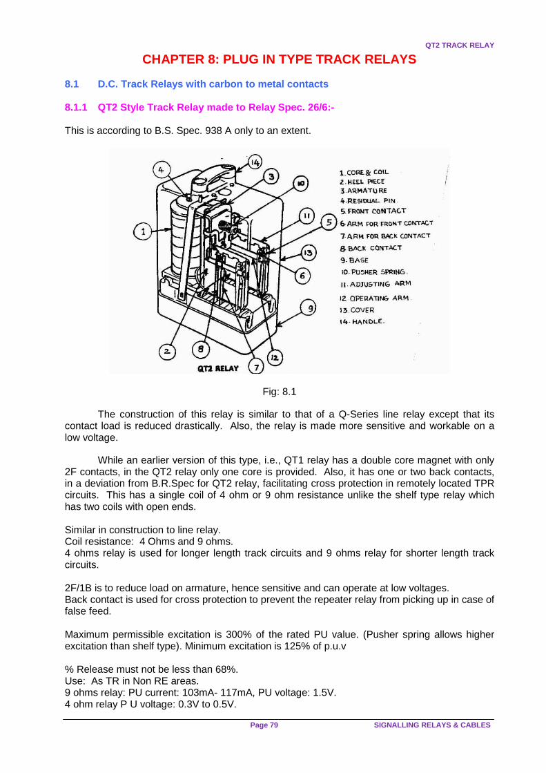
QT2 TRACK RELAY
Page 79 SIGNALLING RELAYS & CABLES
CHAPTER 8: PLUG IN TYPE TRACK RELAYS 8.1 D.C. Track Relays with carbon to metal contacts 8.1.1 QT2 Style Track Relay made to Relay Spec. 26/ 6:- This is according to B.S. Spec. 938 A only to an extent.
Fig: 8.1
The construction of this relay is similar to that of a Q-Series line relay except that its contact load is reduced drastically. Also, the relay is made more sensitive and workable on a low voltage.
While an earlier version of this type, i.e., QT1 relay has a double core magnet with only 2F contacts, in the QT2 relay only one core is provided. Also, it has one or two back contacts, in a deviation from B.R.Spec for QT2 relay, facilitating cross protection in remotely located TPR circuits. This has a single coil of 4 ohm or 9 ohm resistance unlike the shelf type relay which has two coils with open ends. Similar in construction to line relay. Coil resistance: 4 Ohms and 9 ohms. 4 ohms relay is used for longer length track circuits and 9 ohms relay for shorter length track circuits. 2F/1B is to reduce load on armature, hence sensitive and can operate at low voltages. Back contact is used for cross protection to prevent the repeater relay from picking up in case of false feed. Maximum permissible excitation is 300% of the rated PU value. (Pusher spring allows higher excitation than shelf type). Minimum excitation is 125% of p.u.v % Release must not be less than 68%. Use: As TR in Non RE areas. 9 ohms relay: PU current: 103mA- 117mA, PU voltage: 1.5V. 4 ohm relay P U voltage: 0.3V to 0.5V.

PLUG IN TYPE TRACK RELAYS
IRISET Page80
8.1.2 QTA2: AC immunized DC neutral track relay. S pec: BRS 939A.
QTA2 RELAY
Fig: 8.2 This accords with B.R. specifications 939A and 966 F to an extent.
In this relay, a copper slug is provided on the core at its armature end to make it immune to A.C. In all other respects, it is similar to QT2 relay in construction. Its coil resistance is 9 ohms, which can ensure A.C. immunity of not less than 50V. 20 ohms coil QTA2 relays are also available.
Due to the provision of copper slug, the relay requires more DC operating power and it takes more time for its pick up and release.
Only QSPA1 relay is permitted to be used as TPR with this track relay. This is because an unsafe condition shall not be created during the catanery short circuit conditions, when A.C. voltage drop in a track circuit rail increases manifold, the TR may pick up under train and remain so for over 250 m sec. The circuit breaker in the traction power substation takes about 300 m sec. to trip. In this context, QSPA1 relay’s use as TPR is safer as it takes a longer time to pick up. A/C Immunity level 50V AC rms.
Contacts 2F/1B.
9 ohm relay is standard and 20 ohms relays is also available.
Being sensitive relay its DC PU value should not change by a larger extent hence the limitation
on the AC immunity, same as in shelf type.
Max length of Track circuit is 450mtrs. (Rail voltage drop is 10V /90mtrs of track circuit).
QSPA1 only is to be used as repeater relay with QTA2.
20 ohm relay: PU volts: 1.4 to 2.0V, PU current: 80mA to 90mA.
9 ohm relay: PU volts: 1.0 to 1.4V, PU current: 120mA to 140 mA.

REVIEW QUESTIONS
Page 81 SIGNALLING RELAYS & CABLES
8.1.3 QBAT: Biased AC immunized Track Relay. MADE T O RDSO Spec. 84/88: This also accords with B.R.Specn. 939 A and 966F to an extent.
Fig: 8.3
This is a track relay with an improved immunity level of 80V A.C. by the provision of a biasing permanent magnet on its core along with its copper slug. This biasing by initially polarizing the core strengthens its electro-magnetic flux created in the correct direction by coil current. This takes more AC voltage to disturb the DC working flux.
This relay also requires QSPA1 relay as its TPR for the same reasons specified in the case of QTA2 relay.
Construction same as QBCA1 excepting for contacts.
PM is for biasing and also contributes to raising AC immunity level.
Copper slug for AC Immunity.
Contact configuration: 2F/2B.
PU volts: 1.1 to 1.75V, PU current: 140mA to 175 mA.
ACI: 80V,
Coil resistance: 9 ohms.
Max length of track circuit: 720mtrs and can be extended to 750mtrs by using a choke at relay end and feed end Maximum excitation: 235% of P.U.V only because of the flux of P.M.
In case of block joint defective, a normal neutral track relay may pick up by the polarity from the
adjoining track but a biased track relay will not pick up.
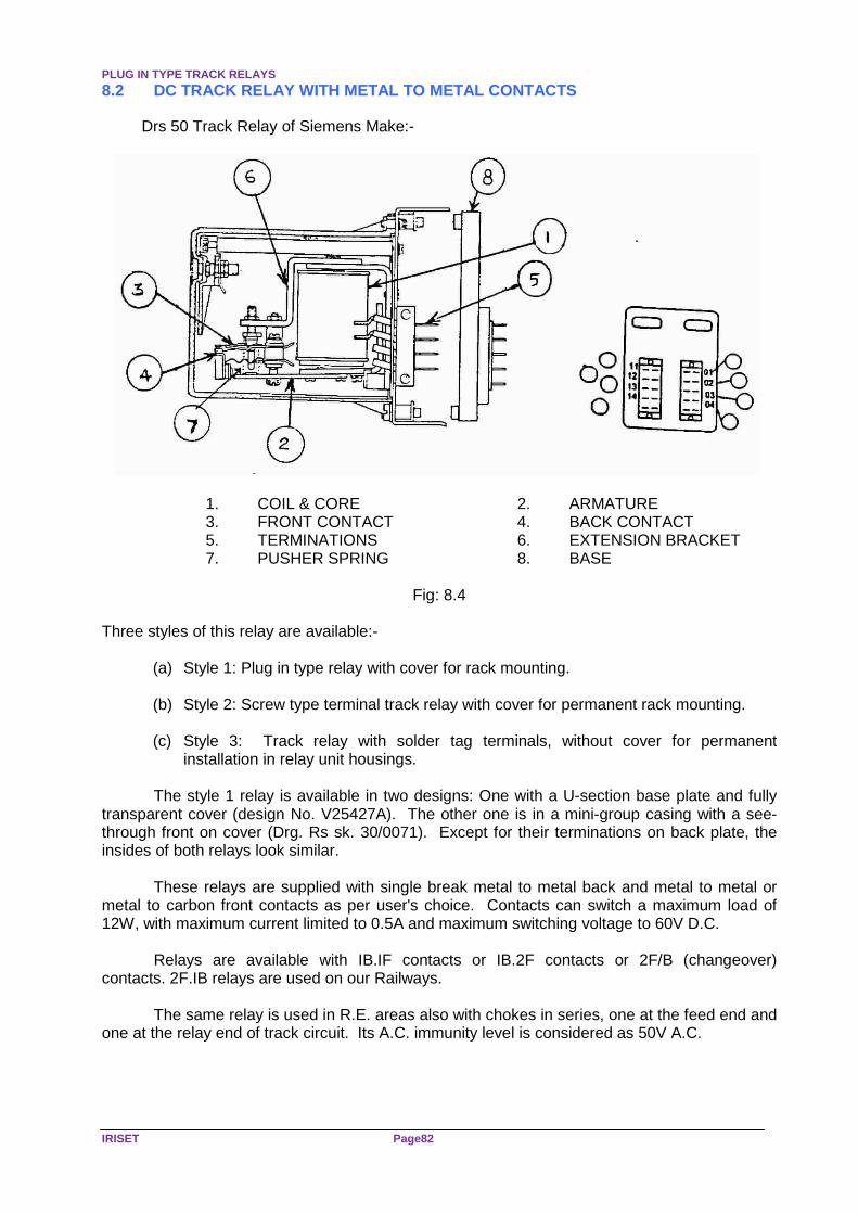
PLUG IN TYPE TRACK RELAYS
IRISET Page82
8.2 DC TRACK RELAY WITH METAL TO METAL CONTACTS Drs 50 Track Relay of Siemens Make:-
1. COIL & CORE 2. ARMATURE
3. FRONT CONTACT 4. BACK CONTACT 5. TERMINATIONS 6. EXTENSION BRACKET 7. PUSHER SPRING 8. BASE
Fig: 8.4
Three styles of this relay are available:-
(a) Style 1: Plug in type relay with cover for rack mounting. (b) Style 2: Screw type terminal track relay with cover for permanent rack mounting. (c) Style 3: Track relay with solder tag terminals, without cover for permanent
installation in relay unit housings.
The style 1 relay is available in two designs: One with a U-section base plate and fully transparent cover (design No. V25427A). The other one is in a mini-group casing with a see-through front on cover (Drg. Rs sk. 30/0071). Except for their terminations on back plate, the insides of both relays look similar.
These relays are supplied with single break metal to metal back and metal to metal or metal to carbon front contacts as per user's choice. Contacts can switch a maximum load of 12W, with maximum current limited to 0.5A and maximum switching voltage to 60V D.C.
Relays are available with IB.IF contacts or IB.2F contacts or 2F/B (changeover) contacts. 2F.IB relays are used on our Railways.
The same relay is used in R.E. areas also with chokes in series, one at the feed end and one at the relay end of track circuit. Its A.C. immunity level is considered as 50V A.C.

REVIEW QUESTIONS
Page 83 SIGNALLING RELAYS & CABLES
Review Questions
Subjective
1) Write a note on QT2 relay in details 2) Write a note on QTA2 relay in details 3) Write a note on QBAT relay in details 4) Write a note on metal to metal track relay
Objective
1) Specification QT2 relay ------------------ 2) Specification of QTA2 ------------------------ 3) Specification of QBAT -------------------- 4) Coil resistance of QBAT relay is ------------- 5) By providing QBAT RELAY track length can be increased up to ----------

SIEMENS THERMO FLASHER UNIT
IRISET Page84
CHAPTER 9: SIEMENS THERMO FLASHER UNIT 9.1 Drg. No.RS SK 30/0096 for 12V operation, 30/0097 for 220V operation & 30/0098 for
110V operation.
Fig: 9.1
The thermo flasher serves the purpose of periodically interrupting light circuits there by
bringing about flashing operation of light signals and indicating lamps.
An oscillating mercury column enclosed in a U-shaped glass tube obtains the periodical flashing of about 60 impulses per minute. The movement of mercury column is caused by hydrogen gas in an interconnected glass chamber. In the lower portion of the gas chamber, a heating element is placed.
When current is passed through the filament of heater, gas expands and exerts pressure on the mercury column in one limb. With depression of the column in one limb, the contact of the heating element 'g/a' breaks. The mercury column then returns to its original position by force of gravity. Now, the heating circuit is closed again. This procedure gets repeated and swings the mercury column continuously till the external feeding circuit is opened. This opens and closes the contacts b/a, c/a, d/a, e/a & f/a, alternatively, which can be used for the required indication controls.
Fig: 9.2

REVIEW QUESTIONS
Page 85 SIGNALLING RELAYS & CABLES
9.2 RELAY DATA: 1. Coil (heating circuit input 12V D.C/A.C or 110V/220V AC (With built in transformer). 2. Approx. power input 9W @ 12V and during heating impulse 20W @ 110/220V. 3. Approx. mean rate of 4.5W @ 12V and power input 10W @ 110/220V. 4. Flashing frequency 60/ minute. 5. Flashing ratio for contacts d/a, e/a, f/a - Bright/Dark=1:1 for contacts c/a & g/a -Bright/Dark = 1:0.5 6. Contact Load Capacity:
Current on contact - 6A @ 12V, 2A @ 110V & 1A @ 220V. Incan descant lamp load - 72W @ 12V, 220W @ 110V & 220V.
7. Terminals Sleeve terminal for a conductor cross section of 2.5mm2. 8. Placing into operation before installation of the flasher unit, check if the Mercury level in the pendulum tube coincides with 'full' mark. If not, tilt housing carefully to bring Mercury into the pendulum tube. This type of Relays are used in Siemens RRI Installations
Review Questions
Subjective 1) Draw a diagram of Siemens flasher relay 2) Explain working of Siemens flasher relay 3) Give the features of Siemens flasher relay 4) In which ckt we are using Siemens flasher relay and why? Objective 1) Metal used in Siemens flasher relay is --------------- 2) Specification of Siemens flasher relay is --------------- 3) Flashing frequency is ------------ 4) Contact load capacity is ----------- 5) Point indication flashing means --------------------

SLOW ACTING RELAYS
IRISET Page86
CHAPTER 10: SLOW ACTING RELAYS 10.1 Slow acting relays are so called because their operation is delayed for a period of a few seconds or mili-seconds to keep circuits controlled by them live even after their own feed is cut off. This is necessary to maintain certain operational sequences.
DC Relays of this type only are popular in our installations, as the delay in operation is obtained in them by electrical means. In AC relays the delay is obtained by means like clock work mechanisms. These relays may be classified as: -
(a) Slow pickup and release relays;
(b) Slow pick up relays, and
(c) Slow release relays. 10.2 Slow pick up and release relays : Provision of copper sleeves on their cores makes them slow to operate.
The following graphs indicate the build up and collapse of fluxes in these relay during
their pick up and release respectively.
Fig: 10.1
The ratio between the inductance and resistance of the relay is its time constant (t = L/R) 10.3 SLOW RELEASE RELAYS:
(a) Sometimes, a rectifier is connected across the relay coil as shown to make it slow to release, with its cathode on the positive side and anode on the negative side.
Fig: 10.2
During the relay coil energisation, the rectifier does not conduct. But when the coil feed is cut off, the collapsing core flux generates a back emf in the coil. This voltage is discharged through the rectifier during which time the relay drop is delayed. The release time lag so obtained is about 250 to 500 milliseconds.

SLOW RELEASE RELAYS
Page 87 SIGNALLING RELAYS & CABLES
(b) The use of a condensor across a relay also makes it slow to release. A resistance may be connected in series with the condensor to limit the initial charging current. The value of resistance also regulates the release time lag. This is the most common arrangement we find in our circuit designs.
Fig: 10.3
10.4 Release time lags Effected by Condensers of di fferent values Connected across Relays:
S.NO Type of Relay Value of capacitance
Release Time lag Actual Time lag
1 DC Shelf type 100 122.8milliseconds 300Ms 2. Line relay 250 Micro farads 307Ms 440milliseconds 3
1000ohms ITI maker 375 Micro farad 481 milliseconds 560Milliseconds
4 Siemens K-50Relay 100Micro farad 955Milliseconds 1second
5 164Micro farads 1566 milliseconds 1700
Milliseconds
6
2000Micro farads 19seconds 25seconds
10.5 Slow to Pick Up Relays:
Fig: 10.4
With a resistance in series and suitable value of capacitance across the relay coil direct,
the relay becomes slow to pick up due to the simultaneous charging of condensor in parallel. During release, the condensor discharges quickly through the relay coil, neutralising the effect of its inductance.
These are used in Circuits for relays –such as TSR, JSLR, RJPR, UYR, Etc

SLOW ACTING RELAYS
IRISET Page88
Review Questions Subjective 1) Where we are using slow to release relays and why? 2) Explain slow to release concept 3) Explain slow to pick up relay concept 4) What is the Basic concept of time delay ckt in relays 5) Give the list of relays made slow to release in Siemens concept Objective 1) QSPA1 is ----------------------to --------- relay used in ------------------concept 2) Diode connected across the coil of relay is connected in --------------------condition 3) Diode across the coil in the Siemens point group -relay is ---------------- 4) Symbol of slow to release relay in British practice is -----------------

DESCRIPTIONOF POLAR RELAY
Page 89 SIGNALLING RELAYS & CABLES
CHAPTER 11: DC POLAR RELAY (Spec. No. S31-80)
Fig: 11.1
11.1 A DC polar relay is one, which makes different contacts for different polarities of DC supply connected to it.
In this relay, a steel strap is polarized by a permanent magnet placed behind and is hinged between the poles of an electromagnet. A movable contact spring called 'arm' is attached to the strap in the front. This spring makes with one of the two fixed contacts on either side when the relay is energized with alternate supply polarities.
When the electromagnet coil is energized with normal polarity, say +ve onR1 and -ve on R2, the south pole at the free end of the strap is attracted towards the north pole of electromagnet to move to the left. Then the arm spring closes with the normal contact of relay on the left.
Similarly, when -ve polarity supply is connected to the coil, +ve on R2 and -ve on R1, the south pole of the strap is attracted towards the right. At this time, the north pole of electromagnet on the right is attracting the free end of the strap, connecting the arm with reverse contact of the relay.
A Polar relay is sensitive to the direction of current and makes different set of contacts for different direction of current flow through the coils.
The working may be explained in easier way by assuming that a permanent magnet is placed in between the pole faces of the electromagnet. In the centre position the permanent magnet flux divides equally on both sides, and there is no force of attraction towards any side but when the coil is energized, the electromagnetic flux causes a variation in the amount of flux on either side of the armature i.e. (QC+QP) on one side, and (QC-QP) on the other. This causes the fluxing of the armature towards the right hand pole face.
In this relay, it is important that, not less than 1.5 mm gap is maintained between the de-energized position of arm and the contact pins on either side. This ensures that the accidental making of contacts due to ground vibration does not take place.

DC POLAR RELAY
IRISET Page90
11.2 Application: This relay is generally used to detect the block line polarity when block handle is turned at the other end of the block section so as to control movement of trains in to the block sections.
Fig: 11.2
Operating characteristics:
(a) Pick up value = 17 MA.
(b) Rated pick up value = 21 MA
(c) Permitted over energisation = 25MA
(d) Resistance = 77 ohms (38.5+38.5ohms)
(e) Drop away value = Not less than 50% of pick up value.
(f) AC Immunization = 10 V AC
(g) Current carrying capacity = a. continuous = 1 Amp Of a contact b. for 30 sec = 2 Amp
(h) Contact resistance when Energized with 10% Excess of the P U Value = 0.25 ohms
Review Questions Subjective
1) Draw a diagram of polar relay 2) Write a note on working of polar relay 3) What are the Operating characteristics polar relays? 4) What is the specification of polar relay?
Objective
1) Total resistance of polar relay is ----------- 2) Pick up value of polar relay -------- 3) Drop away value of polar relay is --------- 4) Polar relay is used in ------------block instrument 5) Contact resistance is -----------
--

TYPES OF CABLES
Page 91 SIGNALLING RELAYS & CABLES
CHAPTER 12: SIGNALLING CABLES
12.1. Type of Cables:
PVC insulated PVC sheathed and armoured signalling cables to specification IRS 5. 63 shall be used for carrying signalling circuits. The conductors used shall be of copper and of approved size. Section view of signalling cable as show in the figure 8.1 . The cables used in signalling installations are broadly classified as:
Fig 12.1 SIGNAL CABLE (a) Indoor cables.
(b) Outdoor cables.
(c) Power cables.
12.1.1 Indoor Cables: Indoors cables are without Armour wire. In this, all the PVC insulated conductors are bunched and kept in thin PVC insulation tube. In addition to indoor cables, wires are also used for internal wiring. Indoor Cables normally used are 60 core(C), 40C, 24C, 20C and 16C cables. In any cable, all the conductors have equal cross section/diameter(Ø). In these cables, all the conductors used are copper conductors.
Each conductor having 0.6mm diameter available in the core of 60C, 40C, 24C and 20C. Each conductor having 1mm. Ø available in the core of 60C, 40C, 24C and 16C. , 0.4 mm and 16 strand 0.2 mm diameter loose flexible wires. Indoor cable conductors can be numbered according to colour code as shown below
1 2 3 4 5 6 7 8 9 10
Blue Red Grey Green Brown Black Yellow with Red dots White Pink Violet

SIGNALLING CABLES
IRISET Page92
Fig 12.2 INDOOR CABLE
• 1mm. Ø copper-single strand wire is used for high current circuits such as signal lamp
circuit, point operation circuit, gate circuit, etc.
• 0.6mm. Ø copper-single strand wire is used for relay wiring.
• 0.4mm. Ø copper-single strand wire is used for indication lamps and panel wiring.
• 16 strand 0.2mm. Ø flexible loose wire is used for Q-Series relay wiring.
12.1.2 Outdoor Cables:
In these cables, all conductors used are copper conductors having equal diameter with PVC insulation. All the PVC insulated conductors are bunched and kept in PVC insulation tube. On the circumference of this tube, galvanised iron rectangular or circular cross section wires called Armour is provided to give the mechanical strength and to protect the cable from damages. On this Armour PVC insulated thick tube is provided to give the more mechanical strength and good insulation resistance in addition to (water proof arrangement) preventing the water entering inside the cable.
Generally, used conductor core sizes are 1.5 sq.mm., 2.5sq.mm., 4sq.mm. Each size is available in the core of all the cables as mentioned below. Most commonly used cores are 2C, 4C, 6C, 8C, 9C, 12C, 18C, 20C, 24C, 30C and 37C. But, rarely used cores are 3C, 5C, 7C, 11C, 14C, 18C, 19C, 21C, 24C, and 30C.
Numbering of conductors in an Outdoor Cable: In these cables, conductors bunched in the form of layers. Numbering is generally started from outer most layers of conductors. Each layer starts from blue conductor and ends with yellow conductor.

OUTDOOR CABLES
Page 93 SIGNALLING RELAYS & CABLES
Outdoor Cable numbering:
Fig 12.3 OUTDOOR CABLE 4C Cable: 1 2 3 4 Blue Black Red Yellow 12C Cable:
Outer Layer
1 2 3 4 5 6 7 8 9 10
Blue Grey Grey Grey Grey Grey Grey Grey Grey Yellow
Inner Layer
10 11 12
Blue Red Yellow

SIGNALLING CABLES
IRISET Page94
For example:
Fig 12.4 OUTDOOR CABLE 30C Cable:
1st Layer (Outer most Layer)
1 2 - 15 16
Blue Grey Yellow
Outer Layer 17 18 - 25 26
Blue Grey Yellow
3rd Layer (Inner Layer)
27 28 29 30
Blue Black Red Yellow

POWER CABLES
Page 95 SIGNALLING RELAYS & CABLES
(a) in A.C. Electrified Sections: (i) The main cables shall ordinarily be PVC insulated screened and armoured cable to I.R.S.
specification No. S.35/1970 or, Paper Insulated lead sheathed and armoured to I.R. specification No.E.17/1959. However, any metallic sheathed armoured cable having a cable reduction factor of not more than 0.4 at a field strength of 87.5 to 450 volts per km may be used in lieu of the paper insulated lead sheathed and armoured (P.I.L.C) cable.
(ii) The tall cables shall be P.V.C. cables to Specification No. IRS S.63. (b) Power cables laid by Signal & Telecommunication Department for carrying power supply up to 440 volts shall be PVC insulated PVC sheathed and armoured cables to specification IS: 1554-PART I- 1964 with alluminium conductors. The conductor shall suit the electrical load. 12.1.3 Power Cables: Generally used power cables are -
• 70 Sq.mm. aluminum core single strands - 3 & 3 1/2 core cable. • 50 Sq.mm. aluminum core single strands - 3 & 3 1/2 core cable. • 25 Sq.mm. aluminum core single strands - 3 & 3 1/2 core cable. • 25 Sq.mm. (Multi-strand-7) aluminum conductor core, also available in 2C, 3C, 3½C, 4C. • 10 Sq.mm. alluminium single strand - 2C. • 08 Sq.mm. copper conductor single strand - 2C. • 06 Sq.mm. copper conductor single strand - 2C.
Fig 12.5
12.2 PLANNING 12.2.1 While planning for cabling on a route, the number of conductors required, depending upon the circuits required should be first determined. The requirement of conductors for providing telephones for level crossings and for maintainers should also be catered for In addition to that required for signalling circuits.

SIGNALLING CABLES
IRISET Page96
12.2.2 Adequate spare conductors up to a minimum of 10% of the total conductors used shall be provide in each cable. No spare conductors are required if the total number of conductors used is three or less. 12.2.3 Suitable conductor sizes shall be used to ensure that the voltage drop on line is not more than 10%. 12.2.4 Where a number of cables have been laid along a route, the circuits shall be so distributed that cables can be disconnected for maintenance purposes with the least possible dislocation to traffic. 12.2.5 After deciding the size and the number of conductors in the different types of cables to be used on a route, a foot survey along the track should be taken, as far as possible, to avoid cinder stocking yard, water mains, oil pipes, drain/sewage pipes, water columns etc. 12.2.6 The desired route should be shown clearly on cable route plan showing the actual alignment of track, giving offsets from permanent way or permanent structures, the Diagram should indicate the various road and track crossing, crossing with power cables, water and sewage mains and other points of importance. It is preferable to chart the route a route plan on which the existing routes of power cables, etc. are shown. PWI/ICW/Electrical Foreman and such supervisors who are likely to dig in that area for other works may be consulted while finalising the route plan. 12.2.7 Where, due to nature of the cable route, initial outlay and future expansions laying of cables underground is not practicable, cables may be carried on stakes with messenger wire except in A.C. electrified areas.
12.3. Cables Laid Underground
12.3.1 Cables may be laid underground either in trench or in ducts or in cement troughs or in pipes.
12.3.2 While laying cables on platforms, it should be taken in a suitable duct along the platform or under the coping of the platform where they would not be exposed to the sun. 12.3.3 Where cables are laid in ducts, RCC or earthenware ducts may be used. The ducts shall have suitable covers. 12.3.4 Wherever the cable is laid in the ducts, sufficient drain shall be provided at the bottom of the duct. Ducts should be close to the surface so that the cover can be removed easily without digging the earth. When cables are laid in rocky area, it is desirable to protect them with R.C.C. troughs. Where it is necessary to take the cable in between the tracks, it shall be taken below the formation level. 12.3.5 Where several cables of different types have to be laid in the same trench, they shall be laid as far as possible in the following order starting from the main trackside, so that in the event of failures, the maintenance staff can easily recognise the cables:
i) Telecommunication cable ii) Signalling cable or cables
iii) L.T. power cable (less than 660 Volts) iv) H.T. power cables (greater than 660 volts)
12.3.6 A separation of about 10 cm. must be maintained between telecommunication cables and signalling cables. The signalling cables must be separated from power cables by a row of bricks between them. Cables belonging to the Posts & Telegraphs Department or the Electrical Department must not be have laid in the same trench along with Signal & Telecommunication cables.

INSTALLATION OF CABLES
Page 97 SIGNALLING RELAYS & CABLES
12.4. Additional Requirements In 25KV A.C. Electrif ied Areas. 12.4.1 The cable shall be laid so that it is not less than one meter from the nearest edge of the mast supporting the catenary or any other live conductor provided the depth of the cable does not exceed 0.5 meters. When the cable is laid at a depth greater than 0.5 meters, a minimum distance of 3 meters between the cable and the nearest edge of the OHE structure must be maintained. If it is difficult to maintain these distances, the cables shall be laid in concrete pipes for a distance of 3 meters on either side from the mast. When so laid, the distance between the cable and the mast may be reduced to 0.5 meters. These precautions are necessary to avoid damage to the cable in the event of the failures of an overhead insulator. 12.4.2 In the vicinity of traction sub-station and feeding posts, the cable shall be at least one meter away from any metallic art of the O.H.E. and other equipment at the sub-station, which is fixed on the ground, and at least one meter away from the sub-station earthing. In addition, the Cable shall be laid in concrete pipes for a length of 500 meters on either side of the feeding As far as possible, the cable shall be laid on the side of the track opposite the feeding post.
In the vicinity of the switching stations, the cable shall be laid at least one meter away from any metallic body of the station, which is fixed in the ground, and at least 5 meters away from the station earthing. The distance of 5 meters can be reduced to one meter provided the cables are laid in concrete pipes. 12.4.3 Where an independent earth is provided for an 0HE structure i.e. where the mast is connected to a separate earth instead of being connected to the rail, the cables shall be laid at least one meter away from the earth. 12.4.4 Where there is O.H.E. structure along x the cable route the cable trenches shall, as far as possible, be dug not less than 5.5 meters from the centre of the track. 12.4.5 Earthing : The screen and Armour of P.I.L.C. and P.V.C. screened cable shall be earthed at each termination. Where it is difficult to earth cable sheath at an intermediate termination, the sheath and armouring of the cable on one side may be connected to the sheath and armouring of the next cable and the far end of the next cable earthed. It must, however, be ensured that the distance between the two earth does not exceed 1 km. In the case of unscreened cable, the metallic Armour should be earthed as if it is a sheath. The parallel runs of The cable at any should be earthed separately. Earthing of cables in the vicinity of substation /feeding posts should be avoided. 12.5 INSTALLATION 12.5.1 Testing Cable before Laying. 12.5.2 Before the cable is laid, a visual inspection of cable shall be made and it shall be tested for insulation and continuity of the cores. The insulation resistance of new cable shall not be below 200 mega ohms per km. at 200 C. If there is wide disparity between insulation of different conductors, the condition of the cable should be thoroughly checked before permitted its use. 12.5.3 Bedding and armouring shall also be inspected to see that there has been no damage during transit or in storage. 12.5.4 The Inspector commissioning the cable should record the relevant purchase order reference, supplier/ manufacturer, type of cable, size, number of cores, insulation value etc., in a register maintained for this purpose.

SIGNALLING CABLES
IRISET Page98
12.6. Paying Out the Cable. 12.6.1 For paying out cables, the cable drums shall be mounted on cable wheels. 12.6.2 If the cable drums are damaged, the cable shall-be rewound on a good drum and then only, it shall be transported. 12.6.3 The drum on the wheel shall be brought to one end of the trench and the end of the cable freed and laid in the trench. 12.6.4 The cable wheels shall then be rolled along the road or track. 12.6.5 A party of men shall follow the drum and guide the cable from the road into the trench carefully so that the cable is not damaged or unduly bent. 12.6.6 In cases where the wheels are not available or the area is not convenient for rolling the wheels along the route, the drum shall be mounted on an axle at one end of the trench and cable payed out. It should be carried by adequate number of men ensuring that the cable is not damaged and no kink is formed. 12.6.7 In no case, shall the drum be rolled off on to the road for laying the cable and the cable dragged on the ground for laying purposes. 12.6.8 It should be ensured that no kink is formed. 12.7 Cable Laying 12.7.1 Normally cable laying should be commenced only after the relay room and cable termination boxes on the route at the respective station are ready and the cable should be duly terminated at the relay room/C.T. boxes immediately after the cables are laid. However, if, for any reason, the cable is to be laid in advance, special care should be taken to ensure that the coiled cable near the relay room/C.T. boxes is fully protected before and during the construction of the relay room/C.T. boxes and during final termination. The coiled cable should be fully covered with a layer. Of bricks in its entire length and provided with adequate number of cable markers. On no occasion the end of the cable should be left unprotected. 12.7.2 Cables must normally be buried at a depth of 1 m. And surrounded with 0.15 m. sand and protected against damage. In theft prone areas, the cables may be laid at a depth of 1.2 m. With anchoring at every 10 m. In rocky areas where it is not possible to take trench for 1 m. depth, the same may be limited to 0.5 m.
12.7.3 The width of the cable trench should normally be 0.5 meters. The bottom of the cable trench should be levelled and got rid of any sharp materials. In the soft ground, the cable should be laid at the bottom of the trench previously levelled. In rocky ground, the cable should be laid on a layer of sand or sifted earth of 0.05 meter thickness previously deposited at the bottom of the trench. In both the above cases, the cable should be covered with a layer of sand of 0.15-meter thickness and thereafter a protective cover of trough or a layer of bricks should be placed. 12.8. Cable Crossing:
12.8.1 When a cable has to cross the track, it should be ensured that:
(i) The cable crosses the track at right angles. (ii) The cable does riot cross the track under points and crossings; and (iii) The cable is laid in concrete/G.I/ C.I./pipes/ or suitable ducts while crossing the
track.
CABLE LAYING
Page 99 SIGNALLING RELAYS & CABLES
12.8.2 When the cables have to cross culverts, they should be suitably supported and protected. They may preferably be taken through G.I. or concrete pipes. 12.8.3 When cables have to cross a metallic bridge, they should be placed inside a metallic trough, which may be filled, as an anti-theft measure, with sealing compound. The cable should be supported across the bridge in a manner which would involve minimum vibrations in the cable and which will facilitate maintenance work. In A.C. electrified areas where suitable return path may not be available for traction current, an additional thick conductor must be laid along with signalling cable and should be earthed at both ends. 12.9. Cable Markers 12.9.1 Suitable cable markers should be provided every 15 m, along the cable route for easy identification. 12.10 Other Precautions 12.10.1 While laying the cables, in accordance with, the above instructions, the following precaution should be adhered to for the safety of the track: -
(i) Outside station limits, the cable should generally be laid at not less than 5.5
meters from the centre of the nearest track. (ii) Within the station limits the trenches shall preferably be dug at a distance of not
less than 3 m. from the centre of the track, width of the trench being outside the 3 meters distance.
(iii) At each end of the main cable, an extra loop. Length of 6 to 8 meters should
be kept. 12.10.2 It is desirable that the excavation of the trenches is not done in long lengths and does not remain uncovered overnight. It is pm preferable that trenches are dug, cables laid and refilling done on the same day. 12.10.3 The inspecting official who supervises the excavation work shall have the shoring materials ready in hand so that in banks where ashes or loose materials are encountered, shoring can be adopted. 12.10.4 Back filling of the trenches should be done properly and the earth shall be duly rammed and consolidated. 12.10.5 During excavation, the earth of the trenches should not be thrown on the ballast. The earth should be thrown by the side of the trenches away, from the track. 12.10.6 In places where cables are to be laid close to the track, though preliminary digging up to 0.50 m. may be done, excavation to the full depth should be done only just before laying the cables. 12.10.7 The work shall be supervised at site personally by an official of the Signal & Telecommunication Department not below the rank of a Signal Inspector. 12.10.8 When cable is threaded through signal for the-purpose of connecting the signal bulb/ route indicator/junction indicator, it should be done carefully to ensure that cable insulation is not damaged. . As far as possible, the cable should be taken in with the sheath in tact. Cables should not be forced through smaller holes in the signal post.

SIGNALLING CABLES
IRISET Page100
12.11 Check of Insulation at the time of Commissio ning:
At the time of commissioning of the cable the insulation values of the cable should again Be checked and the value obtained shall not be below 200 mega ohm per kilometer at 200c.if There is wide disparity between insulation of different conductors, the condition of the. Cable should be thoroughly checked before permitting its use. For converting measured value of Insulation resistance at any temperature to that of 20o C, multiplier constants is given vide Table No.11A of IS: 1554 – 1964 (copy enclosed as Annexure ‘C’)
12.12 Jointing Of Cables In 25KV A.C. Electrified A rea
When underground straight through joints are made, special care must be taken to maintain the electrical continuity of the sheath and armouring. Wiped Joint on M.C. insulated lead or alluminium sheathed cable must be made with the greatest care so that the P.V.C. insulation is not damaged when the sheath is heated for making the joints. 12.13 MAINTENANCE 12.13.1 Testing Of Cables for Faults.
The common faults which develop on conductors of multi-core signalling cables are: - i) Earth ii) Short-Circuit iii) Open -Circuit.
12.13.1 Earth fault develops in a conductor due to defective insulation, which allows the current, carried by the conductor to leak to the earth directly or indirectly instead of going to the apparatus to which the conductor is connected.
Fig: 12.6 INSULATION FAULT
12.13.2 Short circuit occurs when a connection or short develops due to defective insulation between two or more conductors where no connection should exist.
Fig: 12.7 SHORT CIRCUIT FAULT

TESTING OF CABLES
Page 101 SIGNALLING RELAYS & CABLES
12.13.3 Open circuit: It develops if a break occurs in a conductor.
Fig: 12.8 BREAK OR OPEN CIRCUIT.
There are several methods of testing a cable or conductor for finding out the nature of fault developed according to availability of instruments in hand, such as megger, voltmeter or an electric lamp. Method of Testing with a Megger: Megger used for testing signalling cables is 500 Volts DC. For telecom cables is 110 Volts DC. 12.13.4 To Test for an Earth fault:
If the conductor to be tested in the use, both ends must first be disconnected from the circuit of which it forms part. One end is then connected to the megger terminal marked for line. The next step is to connect the other megger terminal E (EARTH) to a good earth. These connections are shown in figure 12.9. Then rotate the meager handle about 80 RPM and while doing this observe where the pointer comes to rest on the scale. If the pointer rests at ZERO, there is a full earth fault in the conductor. If it rests at INF (INITY), it indicates that the insulation of the conductor is O.K. The explanation of this test is very simple. When the megger handle is rotated a voltage is generated which tries to pass a current through the conductor. No current will flow, however, if the insulation is in order as the circuit is not complete. An earth fault, however, will complete the circuit and a current will then pass through the circuit indicated by the arrows of Fig.12.9
Fig: 12.9 EARTH FAULT
12.13.5 To test for a short circuit.
The conductors if in use, must first be disconnected. Then connect them to the megger as shown in figure 12.10, and rotate the megger handle. It will be obvious from the diagram that, if there is no connection between the conductors, no current can flow, and the pointer will come to rest at INFINITY. If, however, the conductors are in contact, a circuit is formed, and the current will cause the needle to indicate ZERO.
Fig: 12.10 SHORT CIRCUIT FAULT

SIGNALLING CABLES
IRISET Page102
12.13.6 To Test for an Open Circuit:
This test can be made in two different ways. One is made by using an earth return, and the other is made by using another conductor known to be o.k. When using an earth return, first connect one end of the conductor to the megger terminal L. Then connect the other megger terminal to good earth. The far end of the conductor should also be connected to a good earth (Fig.12.11). If a second conductor is used to make the test, connect up as shown in Fig.12.12 In both cases, if the conductor under test is unbroken, a circuit is formed, and, when the megger is operated, the pointer will indicate ZERO. Should, however, the conductor be broken the pointer will indicate INIFINITY.
Fig: 12.11 & 12.12 BREAK OR OPEN FAULT
While testing with a megger, the megger itself supplies the circuit necessary for testing, whereas a supply must be available for testing with a voltmeter or a lamp. The supply may be A.C/D.C. or a battery. The range of the voltmeter or the lamp voltage should be the same as that of the supply.
Method of Testing with a Voltmeter of a Lamp: 12.13.7 Earth Fault: The circuit for this test is almost the same as that used for testing with a Megger.
Fig: 12.13 EARTH FAULT
The supply is applied to the conductor to be tested through a voltmeter or a lamp. The
other pole of the supply is connected to the earth. In case a fault exists, if the voltmeter is used for testing it will give a reading or if a lamp is used, the same will glow. If the lamp glows very brightly or a high reading is obtained on the voltmeter, a dead earth fault is indicated.
12.13.8 Short Circuits: The circuit employed is almost similar to that used while testing with a megger. With this kind of fault, there will be glow on the lamp or a reading on the voltmeter as the case may be.

SHORT CIRCUIT & OPEN CIRCUIT
Page 103 SIGNALLING RELAYS & CABLES
Fig: 12.14 SHORT CIRCUIT FAULT
12.13.9 Open circuit: The circuit is similar to that used for a Megger Test. There will be no glow on the lamp or no reading on the voltmeter if there is an open circuit on the cable.
Fig: 12.15 OPEN CIRCUIT FAULT
Useful Hints: The following are a few useful tips which if they are carefully observed, will prevent mistakes and damage instruments when tests are made: -
a) Make sure that each circuit is set up correctly. b) Make sure when testing for earth, that the far end of the conductor is not touching,
otherwise the test will show faulty insulation when such is not actually the case. c) Make sure that the earth used when testing for earth and open circuits is a good one
otherwise the test will give wrong information. The armoring and lead covering of cable usually but not always is relied upon especially that on the cable under test. If, however, when these are used, no fault is indicated, connect up to another earth before deciding whether the cable insulation is good.
d) Make sure that all connections in the test circuit are tight. It is quite common for a
wire to slip off/a terminal in a circuit, which has been put together hastily. e) Test the megger before use. Do this by operating it at the proper speed while it is
disconnected and observing whether the pointer registers INFINITY. Then connect the two terminals together and observe whether the pointer swings immediately to ZERO when the handle is slowly rotated.
f) Make sure that the correct voltmeter or lamp is used. If the voltmeter is not the right,
one it might burn out. If the correct lamp is not used, it might burst, Test the lamp frequently as the filament breaks very easily.
g) Make sure that the wires used to connect up the circuits are good. Electric light flux
is not, recommended for this purpose, unless it is brand new. h) Always be prepared to find more than one kind of fault on a conductor.
12.13.10 Insulation Resistance tests should be made in such a manner that safe operation of trains is not affected. While conducting the tests, it should be ensured that no unsafe conditions are set up by the application of test equipment.
12.13.11 All conductors in signalling cables must be tested for their insulation in dry weather every year preferably during the same part of the year.

SIGNALLING CABLES
IRISET Page104
12.13.12 The insulation Resistance Tests should be made when conductors, cables and insulated parts are clean and dry.
12.13.13 In addition to regular testing of the cable in dry weather, random tests in wet weather may also be carried out where considered necessary. Spare cores may be tested for insulation once a year during monsoon periods to check. 12.13.14 The conductors of the cables possess appreciable electrostatic capacity and may Accumulate electrostatic charge. The cable conductors should be shorted or earthed to completely discharge any accumulated charge:
(i) Before connecting the insulation tester while commencing he test and
(ii) Before the Insulation tester is disconnected when the test is completed.
This is in the interest of safety of personnel and protection of equipment.
12.13.15 A 500V insulation tester should be used for insulation testing. The fact that the cable has capacitance means that it has to be charged before a measurement of the insulation resistance can be made. The insulation resistance should therefore be recorded after the test voltage has been applied for one minute or so when the indicator of the insulation meter shows a steady reading. 12.13.16 Any metallic sheath or metal work of any rack or apparatus case should be bonded to earth during test. 12.14. Procedure: 12.14.1 Disconnect all cores of a cable at both ends. The disconnection may be made through links of ARA terminals if provided. 12.14.2 Connect one terminal of the insulation tester to the conductor under test and other terminal to all the other conductors being bunched together and connected to earth. 12.14.3 Similarly, test remaining conductors of the cable one by one as in 14.2 12.14.4 Insulation resistance so measured should not be less than 20 mega ohms irrespective of the length of cables. In such cases where it is less than 20 mega ohms, the periodicity of testing should be increased to twice a year. If the insulation value is found to be less than 10 mega ohms, the cause should be investigated and immediate steps taken to repair or replace the cable to prevent any malfunctioning of the equipment and circuits. The conductors, which are showing below 05 mega ohms, should be identified and till the defects are rectified, these conductors shall not be used for any circuit. Such defective conductors shall be provided with distinctive markings at both the ends of termination for ease of identity during normal maintenance. 12.14.5 The results of the insulation resistance tests should be recorded in approved proforma enclosed as Annexure ‘B’. A comparison of test results between successive tests carried out on a cable under similar conditions will give an indication of the trend towards the deterioration of the insulation resistance of the cable. If any sudden fall in the insulation resistance is observed, the cause should be investigated and immediate steps taken to repair or replace the cable. 12.15 All cable termination devices, pillar-boxes, cable heads and glands shall be kept clean and dry. These parts shall be frequently inspected and any tendency for moisture or water leak shall be immediately attended to.

REVIEW QUESTIONS
Page 105 SIGNALLING RELAYS & CABLES
12.16 No excavation in the vicinity or underground signal cables shall be undertaken without a representative of the Signal & Telecommunication __ being present and without taking suitable precautions for the safety of the staff. Instructions in this regard issued vide Joint Circular No.___S5/1 date. 22.12.1983 of CE/CSTE (copy attached as Annexure ‘D’) shall be followed. During their maintenance schedules, if the Inspectors/___come across any unauthorised excavation or ___in the vicinity of cables in deviation from the procedure laid down in the Joint Circular, they shall immediately report the matter to their superiors and also take necessary action to protect the cable. 12.17 The protective works provided for the Cables, at places like track crossings, culverts, bridge etc., shall be regularly inspected by the cable maintenance staff, special attention being paid, to these protective works soon after the monsoon. 12.18 Special Requirements in 25 KV A.C. Electrifi ed Areas :
The condition of earth should be inspected'' regularly by maintenance staff and the value of the earth resistance shall not exceed 10 ohms. 12.19 Earth Leak Detector.
The use of earth leak detector devices is desirable in all modern signalling installations, such as Route Relay interlocking, Panel Interlocking and Centralised Traffic Control. 12.20 Periodical Inspection of Cable Route by Maint enance Staff:
The cable route should be periodically inspected by the maintenance staff to detect the following occurrences, if any, which can result in future/damage to the cables:
i) Any unauthorised excavation; ii) Any disturbance to formation; iii) Any other unusual features such as unauthorised occupation stocking of
coal/cinder, water stagnation etc. If any such occurrences are detected, remedial action should be taken forthwith.
Review Questions
Subjective 1) Write a note on indoor cable 2) Write a note on outdoor cable 3) What are different sizes in power cable? 4) What are the additional requirements in RE AREA? 5) Write a note on testing of cable before installation
Objective 1) PVC insulated screened and armored cable to I.R.S. specification--------------- 2) --------Insulation tester should be used for insulation testing 3) Outside station limits, the cable should generally be laid at not less than -----meters from the centre of the nearest track. 4) Within the station limits the trenches shall preferably be dug at a distance of not less than --- m. from the, centre of the track 5) Width of the trench being outside the ------meters distance.

ANNEXURE ‘A’
IRISET Page106
ANNEXURE 'A'
(Signal Engineering Manual) Para, 614 - Underground cables
(a) Cable when laid underground, must normally be buried of a depth of 1 m. and surrounded with 0.15 m. sand and protected against damage. Cable makers marked "signal Cable" should be provided to indicate to the staff the position of the cable.
(b) Where an underground cable leaves the ground, it should be suitably protected. The
protecting arrangement should be properly secured. Para 615 - Cable carried on a Messenger wire. Cables, when carried on a messenger wire, must be supported by cable hangers of adequate strength spaced at intervals of not more than 1 m. The messenger wire must be kept taut to prevent undue sagging. Para 616 - Cables carried on Stakes: Cables, when carried on stakes above ground, should be suitably supported to prevent undue sagging. Para 617 - Paper insulated Cables: Where paper insulated cables are installed, extreme care must be taken that no moisture enters the cable s. The cables must be terminated in pot heads and properly sealed. Each conductor must be jointed to a separate tail insulated wire inside the pot-head and the pot-head filled with suitable insulating compound. Para 618 - Protection of outer Covering : Outer covering of lead sheath and armoured cables laid above ground should be protected from weather effects by a coat of tar coal or any other protective material. Para 623 –Storage, Handling and care of wires and c ables:
(a) Wires and cables should be stored under cover and must be effectively sealed. (b) Precaution must be taken to prevent kinking or twisting of wire. Should any kink or
twist occur, it must be removed carefully. (c) Insulation must not be damaged and must be kept free from oils, grease, acids and
alkalis. (d) Wire and cable entrances must be properly sealed.
Para 625
Labelling - All leading in wires, cable leads and terminal strips must be labelled showing
their designation corresponding to that shown on the circuit diagram.
Each junction box must be equipped with a card schedule, indicating the name and use of each wire the labelling must be done before a work is brought into service.

TESTING OF SIGNALLING CABLES
Page 107 SIGNALLING RELAYS & CABLES
Testing of Signalling Cables. Para 963
All conductors in signalling cables must be tested for their insulation in dry weather every
year, comparison of the test results between successive tests carried on a cable under similar conditions will give an indication of the trend towards deterioration of the insulating material over a period of time. If a sudden fall in insulation is observed the case should be investigated and immediate steps. A taken up to repair, or replace the cable.
In addition to the regular testing of cables in dry weather, random tests in wet weather may also be carried out, where considered necessary, to localise any sudden deterioration in insulation of cables. Para 964 - Earth leak indicators & Earth leak prote ctors.
The use of these devices may also be considered for modern signalling installations such as Route Relay, Interlocking, Panel Interlocking & Centralised traffic Control systems.

ANNEXURE ‘B’
IRISET Page108
ANNEXURE ‘B’ Proforma for Cable Testing
____________ Railway Station ___________________
CABLE INSULATION RESISTANCE TEST SHEET
Main/Tail* Cable
1. Location: From . . . . . . . . . . . . . . . . To . . . . .. . . . . . . . . . .
2. Cores: .
3. Size: .
4. Grade 250/440/650/110OV
5. Length:
6. Type: Unscreened/Screened
7. Insulation: PVC/Paper *
8. Date of installation/Commissioning . . . .
9. Name of the manufacturer: . . . . . . . . . . .
* Strike out whichever is not applicable. - - - - - - - - - - - - - Core No. Date of Test or Designation and whether wet, damp or dry. - - - - - - - - - - - - - Temperature: Remarks: Signature
These instructions are to be followed in addition to those contained in paras 614 to 618, 623 to 625, and 963/964 of the Signal Engineering Manual (Given in Annexure ‘A’)

SPECIFICATION OF RELAYS
Page 109 SIGNALLING RELAYS & CABLES
ANNEXURE – C Relay Specifications and Relay Data Sheets Sl.No. 01 HNA RELAY HYTRONICS ENTERPRISES DESCRIPTION OF RELAY • Relay AC IMMUNISED DC Miniature plug in
neutral line, tractive armature, 24V DC, with plug board retaining clip and connectors.
SPECIFICATION • BRS-931A
IRS:S:34, IRS:S:23 (As Applicable) IRS:S:60 (As Applicable).
• As per clause 13.1 of BRS-931A. NO OF CONTACTS
No of Independent contacts
F 12 8 8 6 4
B 4 8 4 6 4 F = Normally open = Front contact B = Normally close = Back contact
CONTACT RATING . Clause 12.1 of BRS—931 TYPE OF CONTACTS . Metal to Carbon contacts ie 99.99% Silver to SIG
(Silver Impregnated Graphite contact) NOMINAL VOLTAGE . 24V DC MAXIMUM POWER CONSUMPTION Clause 18.1 (b) of BRS—93l. OPERATING VALUES • Clause 18.2 of BRS—93l INSULATION RESISTANCE • > 500 mega ohms. HIGH VOLTAGE • Clause 21.1 of BRS—931. BREAKDOWN TEST CONTACT Resistance < 200 milli ohms COIL RESISTANCE Clause 16.1 of BRS—93l CONTACT PRESSURE Clause 15.1 of BRS—931 OPERATING TIME Clause 18.3 of BRS—931 AC IMMUNITY Clause 18.4 of BRS—931 CONTACT LIFE clause 8.1 & 8.2 of BRS-31
Sl.No. 02 HN RELAY HYTRONICS ENTERPRISES DESCRIPTION OF RELAY • Relay DC Miniature plug in neutral line, tractive armature, 24V DC, with plug board retaining clip and connectors.

ANNEXURE ‘C’
IRISET Page110
SPECIFICATION • BRS-930A IRS:S:34, IRS:S:23 (As Applicable) NO OF CONTACTS As per clause 13.1 of BRS—930A.
No of Independent contacts
F 12 8 8 6 4
B 4 8 4 6 4 F = Normally open = Front Contact B = Normally close= Back Contact
CONTACT RATING • Clause 12.1 of BRS—930
TYPE OF CONTACTS • Metal to Carbon contacts i.e. 99.99% silver
to SIG (Silver Impregnated Graphite Contact)
NOMINAL VOLTAGE • 24VDC MAXIMUM POWER CONSUMPTION • Clause 18.1(b) of BRS—930. OPERATING VALUES • Clause 18.2 of BRS—930 INSULATION RESISTANCE • >500 mega ohms HIGH VOLTAGE • Clause 21.1 of BRS—930 CONTACT RESISTANCE • < 200 mliii ohms COIL ESISTENCE • Clause 16.1 of BRS—930 CONTACT PRESSURE • Clause 15.1 of BRS—930 CONTACT LIFE • Clause 8.1 & 8.2 of BRS—930. Sl.No. 03 HJT RELAY HYTRONICS ENTERPRISES DESCRIPTION OF RELAY • Relay DC Miniature plug in neutral Thermal Time Element, tractive armature 24V DC 2F.1B contacts.120 seconds (fixed). Front & Back contacts metal to carbon hot & cold contacts metal to metal, complete with plug board retaining clip and connectors. SPECIFICATION • BRS-937A IRS: S: 34, IRS: S: 23 (As Applicable)

SPECIFICATION OF RELAYS
Page 111 SIGNALLING RELAYS & CABLES
NO OF CONTACTS • As per clause 14.1 of BRS—937A
Code No Voltage Contact Arrangement
123 24 2F.1B 124 50 2F.lB
F= Normally open Front Contact B= Normally close = Back Contact
THERMAL UNIT • Clause 8.1 & 8.2 & 8.3 of BRS—937 NOMINAL VOLTAGE • 24VDC TYPE OF CONTACTS • Metal to Carbon contacts ie 99.99% silver to SIG(Silver Impregnated Graphite contact) AMBIENT TEMPERATURE RANGE • Clause 10.1 of BRS—937 MAXIMUM POWER CONSUMPTION • Clause 18.1 (b) of BRS—930. OPERATING VALUES • Clause 11.3 of BRS—937 INSULATION RESISTANCE • > 500 mega ohms Clause 21.1 of BRS—930 HIGH VOLTAGE BREAKDOWN TEST : Clause 21.1 of BRS -930 CONTACT RESISTANCE : < 200 milli ohms COIL RESISTANCE : Clause 16.1 of BRS—930 CONTACT PRESSURE : Clause 15.1 of BRS—930 CONTACT LIFE : Clause 8.1 of BRS—930 ADJUSTMENT OF : Clause 11.1 & 11.2 & 11.3 & 11.4 of BRS—937 THERMAL UNIT Sl.No. 04 UECR RELAY HYTRONICS ENTERPRISES DESCRIPTION OF RELAY : Relay DC Miniature plug in lamp proving relay unit to work in series with the lighting circuit of junction type route indicator (five lamps 11OV/25 watt. i.e. SL.33 double pole in parallel) to prove the Continuity of the route indicator lamps circuit. SPECIFICATION • BRS—941 & IRS:S:46 IRS:S:34, IRS:S:23 (As Applicable)

ANNEXURE ‘C’
IRISET Page112
NO OF CONTACTS • As per clause 13.1 of BRS—94lA. No of Independent contacts F 4 B 4 F = Normally open = Front Contact B = Normally close= Back Contact CONTACT RATING • Clause 12.1 of BRS—94l TYPE OF CONTACTS • Metal to Carbon contacts ie 99.99% silver to SIG NOMINAL VOLTAGE • llOV AC/12V AC OPERATING VALUES • Clause 18.1 & 18.2 of BRS—941 Insulation RESISTANCE • > 500 mega ohms HIGH VOLTAGE • Clause 21.1 of BRS—94l BREAKDOWN TEST CONTACT RESISTANCE • Clause 16.1 of BRS—94l CONTACT PRESSURE • Clause 15.1 of BRS—94l CONTACT LIFE • Clause 8.1 of BRS—941. OPERATING TIME Clause 18.3 of BRS—941 Sl. No. 05 HYTRONICS ENTERPRISES
ECR “ON” ASPECT & “OFF” ASPECT LAMP PROVING RELAY
DESCRIPTION OF RELAY Relay DC Miniature plug in type “ON” & “OFF” ASPECT Lamp Proving Relay unit to work in series with the primary winding of a colour light signal transformer (llOV AC/ 12V AC) feeding 25w/33w i.e. SL.17/ SL.21 double pole double filament continuity of signal lamp circuit. SPECIFICATION BRS—941 & IRS:S:46 IRS:S:34, IRS:S:23 (As Applicable) NO OF CONTACTS As per clause 13.1 of BRS—941A. No of Independent contacts F 4 B 4 F = Normally open Front Contact B = Normally close= Back Contact CONTACTS RATING Clause 12.1 of BRS—94l TYPE OF CONTACTS Metal to Carbon contacts i.e. 99.99% silver to SIG NOMINAL VOLTAGE 11OV AC/12V AC

SPECIFICATION OF RELAYS
Page 113 SIGNALLING RELAYS & CABLES
OPERATING VALUES Clause 18.1 & 18.2 of BRS—941 INSULATION RESISTANCE • > 500 mega ohms HIGH VOLTAGE • Clause 21.1 of BRS-94l BREAKDOWN TEST CONTACT RESISTANCE • Clause 16.1 of BRS—941 CONTACT PRESSURE • Clause 15.1 of BRS—941 CONTACT LIFE • Clause 8.1 of BRS—941. OPERATING TIME Clause 18.3 of BRS—943.
Sl. No. 06 HT-12 RELAY HYTRONICS ENTERPRISES
DESCRIPTION OF RELAY Relay DC Miniature plug in type 1000 ohms, with 4F/4B contacts, Front contacts metal to carbon and back contacts metal to metal to operate on l2V DC. SPECIFICATION BRS—930 IRS:S:34, IRS:S:23 (As Applicable) NO OF CONTACTS As per clause 13.1 of BRS—930 No of Independent contacts F 4 B 4 F = Normally open = Front Contact B = Normally close= Back Contact CONTACT RATING Clause 12.1 of BRS—930 TYPE OFCONTACTS Metal to Carbon contacts i.e. 99.99% silver to SIG (Silver Impregnated Graphite contact) NOMINAL VOLTAGE 12 VDC OPERATING VALUES Clause 18.1 & 18.2 of BRS—930 INSULATION RESISTANCE > 500 mega ohms HIGH VOLTAGE Clause 21.1 of BRS—930 BREAKDOWN TEST CONTACT RESI STANCE Clause16.1 of BRS—930 CONTACT PRESSURE Clause 15.1 of BRS—930 CONTACT LIFE Clause 8.1 of BRS—930
OPERATING TIME Clause 18.3 of BRS—930

ANNEXURE ‘C’
IRISET Page114
Sl. No. 07 HT-1 RELAY HYTRONICS ENTERPRISES DESCRIPTION OF RELAY • Relay DC Miniature plug in neutral, TRACK 4 ohms tractive
armature 2F.1B contact. Front and back contacts metal to carbon, complete with plug board, retaining clip and connectors.
SPECIFICATION • BRS—938 IRS: S: 34, IRS: S: 23 (As Applicable) NO OF CONTACTS • As per clause 13.1 of BRS—938A. No of Independent contacts F 2 B 1 F = normally open = Front Contact B = normally close = Back Contact CONTAC RATING Clause 12.1 of BRS—938 TYPE OFCONTACTS Metal to Carbon contacts i.e. 99.99% silver to SIG (Silver Impregnated Graphite contact) OPERATING VALUES Clause 18.1 & 18.2 & 18.3 of BRS—938 INSULATION RESISTANCE >500 mega ohms HIGH VOLTAGE BREAKDOWN TEST Clause 21.1 of BRS—938 CONTACT RESISTANCE 8.1 & 8.2 of BRS—938. CONTACT PRESSURE Clause 16.1 of BRS—938 CONTACT LIFE Clause 15.1 of BRS—938 OPERATING VOLTAGE Clause 18.3 of BRS—938 Sl. No. 08 3PPR RELAY HYTRONICS ENTERPRISES DESCRIPTION OF RELAY Relay DC Polarized 3 Position 77 ohms resistance 1N/lR
contacts metal to metal centre biased armature. SPECIFICATION • IRS: S: 31—80
IRS: S: 34, IRS: S: 23 (As Applicable) NO OF CONTACTS • As per clause 11.1 of IRS: S: 31—80 CONTACT TERMINAL • As per clause 13.2 of IRS: S: 31—80 CONTACT RATING • Clause 11.6 of IRS: S: 31—80 TYPE OF CONTACTS • Metal to Carbon contacts i.e. 99.99% silver to SIG
(Silver Impregnated Graphite contact) NOMINAL VOLTAGE 24VDC MAGNETIC SYSTEM • Clause 8.1 of IRS: S:31—80

SPECIFICATION OF RELAYS
Page 115 SIGNALLING RELAYS & CABLES
OPERATING VALUES • Clause 16.2 of IRS: S:31—8o INSULATION RESISTANCE • Clause 16.3. of IRS:S:3l—80 HIGH VOLTAGE BREAKDOWN TEST • Clause 16.3. of IRS:S:31—80 CONTACT RESISTANCE Clause11.5 of IRS: S: 31—80 CONTACT PRESSURE Clause11.4 of IRS: S: 31—80 CONTACT CLEARANCE Clause11.3 of IRS: S: 31—80 CONTACT RATING Clause11.6 of IRS: S: 31—80 AC IMMUNITY Clause16.4 of IRS: S: 31—8o COIL RESISTANCE Clause 9.2 of IRS: S: 31—80
Sl. No. 09 HTMN-K RELAY HYTRONICS ENTERPRISES DESCRIPTION OF RELAY :Mini Group with metal to metal contacts with BRS Plug Board. SPECIFICATION IRS: S: 46 IRS: S: 34, IRS: S: 23 (As Applicable) NO OF CONTACTS As per clause 10.1 of IRS: S: 46.
Single wound Relays L.H. Relay R.H. Relay Front Back Front Back 6 2 6 2 4 4 4 4 5 3 5 3 Double wound Relays L.H. Relay R.H. Relay Front Back Front Back 6 2 6 1. 4 3 4 3 5 3 5 3 F = normally open = Front Contact B = normally close= Back Contact
CONTACT RATING Clause 10.6 of IRS:S:46 TYPE OF CONTACTS Metal to Metal contacts i.e. 99.99% silver to Silver NOMINAL VOLTAGE 24V DC/ 60V DC OPERATING VALUES Clause 13.1 of IRS:S:46 INSULATION RESISTANCE >500 mega ohms

ANNEXURE ‘C’
IRISET Page116
HIGH VOLTAGE BREAKDOWN TEST Clause 21.1 of IRS:S:46 CONTACT RESISTANCE Clause 10.5 of IRS:S:46 CONTACT PRESSURE Clause 10.4 of IRS:S:46 OPERATING TIME Clause 7.1, 7.2, 7.3 of ERS:S:46
Sl. No. 10 HTMNA-K RELAY HYTRONICS ENTERPRISES DESCRIPTION OF RELAY AC IMMUNISED Mini Group with Metal to metal contacts with BRS Plug Board. SPECIFICATION • IRS: S: 46 IRS: S: 34, IRS: S: 23 (As Applicable) NO OF CONTACTS • As per clause 10.1 of IRS: S: 46.
Single wound Relays L.H. Relay R.H. Relay Front Back Front Back 6 2 6 2 4 4 4 4 5 3 5 3 Double wound Relays L.H. Relay R.H. Relay Front Back Front Back 6 2 6 1 4 3 4 3 5 3 5 3 F = Normally open = Front Contact B = Normally close = Back Contact
CONTACT RATING Clause 10.6 of IRS: S: 46 TYPE OF CONTACTS • Metal to Metal contacts i.e. 99.99% silver to Silver NOMINAL VOLTAGE • 24V DC! 60V DC OPERATING VALUES • Clause 13.1 of IRS: S: 46 INSULATION RESISTANCE >500 mega ohms HIGH VOLTAGE BREAKDOWN TEST Clause 21.1 of IRS: S: 46 CONTACT RESISTANCE Clause 10.5 of IRS: S: 46 CONTACT PRESSURE Clause 10.4 of IRS: S: 46 OPERATING TIME Clause 7.1, 7.2, 7.3 of IRS: S: 46 AC IMMUNITY Clause 18.4 of BRS—930.

SPECIFICATION OF RELAYS
Page 117 SIGNALLING RELAYS & CABLES
Sl. No. 11 HNN RELAY HYTRONICS ENTERPRISES DESCRIPTION OF RELAY Relay DC miniature plug in neutral line tractive
armature, twin type metal to carbon contacts complete with plug board and retaining clip and connectors.
SPECIFICATION BRS—960 IRS: S: 34, IRS:S:23 (As Applicable) NO OF CONTACTS As per clause 13.1 of BRS—960A. Single wound Relays L.H. Relay R.H. Relay Front Back Front Back 6 2 6 2
4 4 4 4 2 2 2 2
Double wound Relays
L.H. Relay R.H. Relay Front Back Front Back 6 2 6 1
4 3 4 3 2 1 2 1
F = Normally open Front Contact B = Normally close = Back Contact
CONTACT RATING Clause 12.1 of BRS—960 TYPE OF CONTACTS Metal to Carbon contacts i.e. 99.99% silver to SIG (Silver Impregnated Graphite contact) NOMINAL VOLTAGE 24V DC, 60V DC OPERATING VALUES Clause 18.1 (a), (b) BRS—960 INSULATION RESISTANCE >500 mega ohms HIGH VOLTAGE Clause 21.1 of BRS—960 BREAKDOWN TEST CONTACT RESISTANCE Clause 16.1 of BRS—960 CONTACT PRESSURE Clause 15.1 of BRS—960 CONTACT LIFE Clause 8.1 of BRS—960• OPERATING VOLTAGE Clause 18.2 of BRS—960

ANNEXURE ‘C’
IRISET Page118
Sl. No. 12 HNNA RELAY HYTRONICS ENTERPRISES DESCRIPTION OF RELAY Relay AC IMMUNISED DC miniature plug in neutral
line tractive armature, twin type, metal to carbon contacts complete with plug board and retaining clip and connectors.
SPECIFICATION BRS—960 IRS: S: 34, IRS: S: 23 (As Applicable) NO OF CONTACTS As per clause 13.1 of BRS—960A.
Single wound Relays L.H. Relay R.H. Relay Front Back Front Back 6 2 6 2 4 4 4 4 2 2 2 2
Double wound Relays L.H. Relay R.H. Relay Front Back Front Back 6 2 6 1 4 3 4 3 2 1 2 1 F= normally open = Front Contact B= normally close= Back Contact
CONTACT RATING Clause 12.1 of BRS—960 TYPE OF CONTACTS Metal to Carbon contacts i.e. 99.99% silver to SIG (Silver Impregnated Graphite contact) NOMINAL VOLTAGE • 24V DC! 60V DC OPERATING VALUES Clause 18.1 (a), (b) BRS—960 INSULATION RESISTANCE • > 500 mega ohms HIGH VOLTAGE Clause 21.1 of BRS—960 BREAKDOWN TEST
CONTACT RESISTANCE • Clause 16.1 of BRS—960
CONTACT PRESSURE • Clause 15.1 of BRS—960
CONTACT LIFE • Clause 8.1 of BRS—960. OPERATING VOLTAGE • Clause 18.2 of BRS—960
AC IMMUNITY Clause 18.4 of BRS—931

SPECIFICATION OF RELAYS
Page 119 SIGNALLING RELAYS & CABLES
Sl. No. 13 HKMI RELAY HYTRONICS ENTERPRISES DESCRIPTION OF RELAY • Mini Relay Group, plug in type, Mechanically
Interlocked complete with base plate, consisting of 2 nos Mini relays with 4F.4B contacts for operation on 60V DC.
SPECIFICATION IRS: S: 46 IRS: S: 34, IRS: S: 23 (As Applicable) NO OF CONTACTS • As per clause 10.1 of IRS: S: 46.
Single wound Relays L.H. Relay R.H. Relay Front Back Front Back 6 2 6 2 4 4 4 4 5 3 5 3
Double wound Relays L.H. Relay R.H. Relay Front Back Front Back 6 2 6 1
4 3 4 3 5 3 5 3
F = normally open = Front Contact B = Normally close= Back Contact
CONTACT RATING Clause 10.6 of IRS: S: 46 TYPE OF CONTACTS Metal to Metal contacts i.e. 99.99% silver to Silver NOMINAL VOLTAGE 24V DC/ 60V DC
OPERATING VALUES Clause 13.1 of IRS: S: 46
INSULATION RESISTANCE >500 mega ohms
HIGH VOLTAGE Clause 21.1 of IRS: S: 46 BREAKDOWN TEST
CONTACT RESISTANCE Clause 10.5 of IRS: S: 46 CONTACT PRESSURE Clause 10.4 of IRS: S: 46 OPERATING TIME Clause 7.1, 7.2, 7.3 of IRS: S: 46

ANNEXURE ‘C’
IRISET Page120

DATA SHEET FOR ‘Q’ SERIES RELAYS
Page 121 SIGNALLING RELAYS & CABLES

ANNEXURE ‘C’
IRISET Page122
1. TYPE TMA-WKR2 RELAY FOR POINT GROUP. 1. SPECIFICATION
1.1 RELAY TYPE : TMA 1144/121-GUM/OLO ; TMA 1153/121-GUM/OLO & TMA I 162/121-GUM/OLO. 1.2 RELAY RATINGS : Suitable for working in a point detection circuit & relay is rated for continuous current of 250 mA 1.3 CONTACT CONFIGURATION 4F/4B ; 5F/3B & 6F/2B 1.4 RELAY MOUNTING : With or without plug-in-base & with socket. 2 ELECTRICAL PARAMETERS 2.1 COIL RESISTANCE 44Ω+0R -10% AT2O0CC 2.2 PICK UP VALUE <OR= 10.0 VDC&200mADC. 2.3 DROP OFF VALUE UPTO2VDC& >OR= 50 mA. 2.4 HIGH VOLTAGE TEST 2 Ky for sixty seconds (subsequent HV test, Voltage to be 60% of 2 KV, i.e. 1.2 Ky). 2.5 INSULATION RESISTANCE > OR = 50 M ~2 at 500 V DC and during rainy days it shall be > OR = 10 M f) (as per clause 14.3.2.2 & 3 of IRS S23 (Part-Il). 2.6 CONTACT RESISTANCE < OR = 50 m~) measured between contact
knives. 3 MECHANICAL PARAMETERS 3.1 CONTACT PRESSURE >OR=l8Grams. 3.2 CONTACT CLEARANCE >OR=1.Smm. 2. TYPE TMB - AC LAMP PROVING RELAY FOR ON ASPECT W ITH INTERPOSING
CURRENT TRANSFORMER. 1 SPECIFICATION 1.1 RELAY TYPE TMB 1133/401 A-GUM/OLO. 1.2 RELAY RATINGS Suitable for working with colour light signal
transformer, 110 V AC/12 V AC. 1.3 CONTACT CONFIGURATION 3F/3B. 1.4 RELAY MOUNTING With or without plug-in-base, with socket & built-in
bridge rectifier with interposing current transformer. 2 ELECTRICAL PARAMETERS 2.1 COIL RESISTANCE 20.8Ω+OR- 10% AT 200 C.C. 2.2 PICK UP VALUE >OR=200mA AC 2.3 DROP OFF VALUE >OR=90mA AC 2.4 HIGH VOLTAGE TEST 2 Kv for Sixty seconds (subsequent HV test,
Voltage to be 60% of 2 K.V i.e. 1.2 K.V).

SPECIFICATION OF RELAYS
Page 123 SIGNALLING RELAYS & CABLES
2.5 INSULATION RESISTANCE > OR = 50 M ~ at 500 VDC and during rainy days it shall be> OR = 10 M Q
(as per clause 14.3.2.2 & 3 of IRS S23 (Part-li). 2.6 CONTACT RESISTANCE OR = 50 mQ measured between contact knives. 2.7 RATING Relay can withstand continuous current of 320 mA A/C. 2.8 VOLTAGE DROP Voltage drop between terminals R-1 & R2 shall be <or = 10 V at 250 mA, 50 Hz rms. at 20 deg.c.c (as per BRS 941a CL.18.1(A)) 3 MECHANICAL PARAMETERS 3.1 CONTACT PRESSURE OR = 18 Grams. 3.2 CONTACT CLEARANCE >OR=1.8mm. APPLICATION Lamp proving Relay suitable for ‘ON’ aspect double
filament lamps SL17/SL21.
CONNECTION DIAGRAM FOR LAMP PROVING RELAY WITH INTERPOSING TRANSFORMER

ANNEXURE ‘C’
IRISET Page124
3. TYPE TMB - AC LAMP PROVING RELAY FOR OFF ASPECT WITH INTERPOSING CURRENT TRANSFORMER. SPECIFICATION 1.1 RELAY TYPE TMB 1133/401 A- GUM/OLO. 1.2 RELAY RATINGS Suitable for working with colour light signal
transformer, 110 V AC / 12 V AC. 1.3 CONTACT CONFIGURATION 3F/3B. 1.4 RELAY MOUNTING With or without plug-in-base, with socket & built-in bridge rectifier with interposing current transformer. 2 ELECTRICAL PARAMETERS 2.1 COIL RESISTANCE 20.8Ω+OR- 10% AT 200 C.C. 2.2 PICK UP VALUE <OR = 200MA A/C 2.3 DROP OFF VALUE Between 50 TO 80 MA A/C 2.4 HIGH VOLTAGE TEST 2 KV for sixty seconds (subsequent HV test, Voltage to be 60% of 2 K.V, i.e. 1.2 K.V). “NOTE:Diode bridge rectifier should not be subject to H V test”. 2.5 INSULATION RESISTANCE > OR = 50 M 0 at 500 V DC and during rainy days it shall be> OR = 10 M 0 (as per clause 14.3.2.2 & 3 of IRS S23 (Part-Il). 2.6 CONTACT RESISTANCE OR = 50 mΩ measured between contact knives. 2.7 RATING Relay can withstand continuous current of 320 mA AC. 2.8 VOLTAGE DROP Voltage drop between terminals R-1 & R2 shall be <or = 10 V at 250 mA, 50 Hz rms. at 20 deg C.C. (as per BRS 941a CL. 18.1(a)) 3 MECHANICAL PARAMETERS 3.1 CONTACT PRESSURE > OR = 18 Grams. 3.2 CONTACT CLEARANCE > OR = 1.8 mm. 4 APPLICATION
Lamp proving Relay suitable for ‘OFF’ aspect single filament lamps SL18.
CONNECTION DIAGRAM FOR LAMP PROVING RELAY WITH INTERPOSING TRANSFORMER

SPECIFICATION OF RELAYS
Page 125 SIGNALLING RELAYS & CABLES
4. TYPE TMB - AC LAMP PROVING RELAY FOR ROUTE IN DICATOR (WITH OUT CT) SPECIFICATION 1.1 RELAYTYPE TMB 1133/610A-GUM/OLO. 1.2 RELAY RATINGS Suitable for working with five lamps (110 V, 25 W)
connected in parallel. The relay shall remain energised with 3 to 5 lamps (in parallel) of three route indicator working and relays shall get de-energised with the less than 3 lamps working.
1.3 CONTACT CONFIGURATION 3F/3B. 1.4 RELAY MOUNTING With or without plug-in-base, with socket & a bridge rectifier. 2 ELECTRICAL PARAMETERS 2.1 COIL RESISTANCE • 1.690+ OR- 10% AT200 C.C. 2.2 PICK UP VALUE <OR =950mA A/C 2.3 DROP OFF VALUE Between 500 TO 600 ‘mA AC 2.4 HIGH VOLTAGE TEST 2 KV for sixty seconds (subsequent HV test, Voltage to be 60% of 2 KV, i.e. 1.2 KV). “NOTE: Diode bridge rectifier should not be subject to H V test” 2.5 INSULATION RESISTANCE > OR = 50 M 0 at 500 V DC and during rainy days it shall be > OR = 10 M 0 (as per clause 14.3.2.2 & 3 of IRS S23 (Part-Il). 2.6 CONTACT RESISTANCE < OR = 50 mΩ measured between contact knives. 2.7 VOLTAGE DROP Voltage drop between terminals R1 & R2 shall be < < or = 6 V at 1250 mA, 50 Hz rms. at 20 deg C.C.

ANNEXURE ‘C’
IRISET Page126
3 MECHANICAL PARAMETERS 3.1 CONTACT PRESSURE >OR=18 Grams. 3.2 CONTACT CLEARANCE R =1.8mm. 5. TYPE TMB - AC LAMP PROVING RELAY FOR SHUNT SIGNAL . SPECIFICATION 1.1 RELAY TYPE TMBII44/508A-GUM/OLO and TMB 1162/508 A- GUM/OLO 1.2 RELAY RATINGS Suitable for working with shunt signal lamps, considering of 2 numbers 50 V, 25 W lamps in
series.. 1.3 CONTACT CONFIGURATION 4F/4B and 6F/2B. 1.4 RELAY MOUNTING With or without plug-in-base, with socket & a bridge
rectifier. 2. ELECTRICAL PARAMETERS 2.1 COIL RESISTANCE 4.34Ω+OR- 10% AT2O deg.C.C. 2.2 PICK UP VALUE <OR =390mA AC
2.3 DROP OFF VALUE >OR=90mA AC 2.4 HIGH VOLTAGE TEST 2 Kv for sixty seconds (subsequent HV test, Voltage to be 60% of 2 Kv, i.e. 1.2 Kv). “NOTE : Diode bridge rectifier should not be subject to H V test”. 2.5 INSULATION RESISTANCE > OR = 50 M 0 at 500 V DC and during rainy days it shall be > OR = 10 M 0 (as per clause 14.3.2.2 & 3 of IRS S23 (Part-Il). 2.6 CONTACT RESISTANCE < OR = 50 mΩ measured between contact knives. 2.7 RATING Relay can withstand continuous current of 600 mA
AC. 2.8 VOLTAGE DROP Voltage drop between terminals Ri & R2 shall be<or=6Vat 500 mA, 50 Hz rms. at 20 deg C.C. 3 MECHANICAL PARAMETERS 3.1 CONTACT PRESSURE >OR=1.8mm. 3.2 CONTACT CLEARANCE >OR=l8Grams. 4. APPLICATION Suitable for lamp proving for shunt signals, where
two lamps each 50 V. 25 W are connected in series.

SPECIFICATION OF RELAYS
Page 127 SIGNALLING RELAYS & CABLES
6 . TYPE TMB AC LAMP PROVING RELAY FOR ROUTE INDIC ATOR WITH INTERPOSING CURRENT TRANSFORMER.
SPECIFICATION 1.1 RELAY TYPE TMB 1133/401 A (UECR) - GUM/OLO. 1.2 RELAY RATINGS Suitable for working with five lamps (110 V. 25 W)
connected in parallel. The relay shall remain energised with 3 to 5 lamps (in parallel) of three route indicator working and relays shall get de-energised with the less than 3 lamps working.
1.3 CONTACT CONFIGURATION 3F/3B. 1.4 RELAY MOUNTING With or without plug-in-base, with socket &
in-built bridge rectifier with interposing current transformer.
2 ELECTRICAL PARAMETERS 2.1 COIL RESISTANCE 20.80+OR- 10% AT200 C.C. 2.2 PICK UP VALUE OR = 950 mA AC. 2.3 DROP OFF VALUE Between 500 TO 600 mA AC. 2.4 HIGH VOLTAGE TEST 2 KV for sixty seconds (subsequent HV test, Voltage to be 60% of 2 KV, ie. 1.2 KV). NOTE: Diode bridge rectifier should not be subject to H V test”. 2.5 INSULATION RESISTANCE > OR = 50 M 0 at 500 V DC and during rainy days it shall be > OR = 10 M 0 (as per clause 14.3.2.2 & 3 of IRS S23 (Part-Il). 2.6 CONTACT RESISTANCE < OR = 50 mΩ measured between contact knives. 2.7 VOLTAGE DROP Voltage drop between terminals Ri & R2 shall
be<or=6Vat 1250 mA, 50 Hz rms. at 200 C. 3 MECHANICAL PARAMETERS 3.1 CONTACT PRESSURE >OR=l8Grams. 3.2 CONTACT CLEARANCE >OR=i.8mm. 7. TYPE TMA AC-IMMUNISED NEUTRAL LINE RELAY 60 V DC . SPECIFICATION 1.1 RELAY TYPE TYPE TMA of any Contact configuration 1.2 RELAY RATINGS 6OVDC+OR-20%. 1.3 CONTACT CONFIGURATION 4F/4B; 5F/3B & 6F/2B. 1.4 RELAY MOUNTING With or without plug-in-base & with socket.

ANNEXURE ‘C’
IRISET Page128
2 ELECTRICAL PARAMETERS 2.1 COIL RESISTANCE 2100 0+ OR- 10% AT2O C.C. 2.2 PICK UP VALUE <OR48VDC&>OR=2OmA. 2.3 DROP OFF VALUE >OR12VDC&5mA. 2.4 HIGH VOLTAGE TEST 2 KV for sixty seconds (subsequent HV test, Voltage to be 60% of 2 Ky, i.e. 1.2 Ky). 2.5 INSULATION RESISTANCE >OR = 50 MΩ at 500 V DC and during rainy days it shall be > OR = 10 M 0 (as per clause 14.3.2.2 & 3 of IRS 523 (Part-lI). 2.6 CONTACT RESISTANCE < OR 50 mΩ measured between contact 1knives. 2.7 AC IMMUNITY LEVEL (1) Back contact will not break at 300 V AC applied across the coil. (2) Front contact will not make at 750 V AC applied across the coil. 3 MECHANICAL PARAMETERS 3.1 CONTACT PRESSURE : >OR = 18 Grams 3.2 CONTACT CLEARANCE : > OR = 1.8 mm 8. TYPE TMA NEUTRAL LINE RELAY 60 V DC. SPECIFICATION 1.1 RELAY TYPE TYPE TMA of any Contact configuration 1.2 RELAY RATINGS 6OVDC+OR-20%. 1.3 CONTACT CONFIGURATION 5F/3B ; 6F/2B ; 2F/4B ; 2F2B & any other contact
Combination of 8 contacts. 1.4 RELAY MOUNTING With or without plug-in-base & with socket. 2 ELECTRICAL PARAMETERS 2.1 COIL RESISTANCE 1550Ω+OR- 10% AT200 C.C. 2.2 PICK UP VALUE <OR48VDC&>OR16mA. 2.3 DROP OFF VALUE >OR =12VDC&5mA. 2.4 HIGH VOLTAGE TEST 2 KV for sixty seconds (subsequent HV test, Voltage to be 60% of 2 Ky, i.e. 1.2 Ky). 2.5 INSULATION RESISTANCE > OR = 50 M Ω at 500 V DC and during rainy days
it shall be > OR = 10 M 0 (as per clause 14.3.2.2 & 3 of IRS S23 (Part-Il).

SPECIFICATION OF RELAYS
Page 129 SIGNALLING RELAYS & CABLES
2.6 CONTACT RESISTANCE < OR = 50 mΩ measured between contact knives. 3. MECHANICAL PARAMETERS 3.1 CONTACT PRESSURE >OR = 18 Grams. 3.2 CONTACT CLEARANCE >OR = 1.8 mm. 9. TYPE TMA NEUTRAL LINE RELAY 24 V DC.
SPECIFICATION 1.1 RELAY TYPE TYPE TMA of any Contact configuration 1.2 RELAY RATINGS 24VDC+OR-20%. 1.3 CONTACT CONFIGURATION 4F/4B; 5F/3B; 6F/2B; 2F14B; 2F2B & any other contact combination of 8 contacts. 1.4 RELAY MOUNTING With or without plug-in-base & with socket. 2 ELECTRICAL PARAMETERS 2.1 COIL RESISTANCE 390 0+OR- 10% AT2O C.C. 2.2 PICK UP VALUE <OR 19.5VDC&8OmA. 2.3 DROP OFF VALUE >OR 4.8VDC&lOmA. 2.4 HIGH VOLTAGE TEST 2 KV for sixty seconds (subsequent HV test, Voltage to be 60% of 2 KV, i.e. 1.2 Ky). 2.5 INSULATION RESISTANCE > OR = 50 MΩ at 500 V DC and during rainy days it shall be > OR = 10 M 0 (as per clause 14.3.2.2 & 3 of IRS S23 (Part-Il). 2.6 CONTACT RESISTANCE < OR = 50 mΩ measured between contact knives. 3 MECHANICAL PARAMETERS 3.1 CONTACT PRESSURE >OR = 18Grams. 3.2 CONTACT CLEARANCE >OR = 1.8mm. 10. TYPE TMB 3-POSITION CODE RECEIVING RELAY.
SPECIFICATION 1.1 RELAY TYPE TMB 1742/715 A - GSM/GSO. 1.2 RELAY RATINGS AT EACH COIL OR = 68 mA at 12 V DC. 1.3 CONTACT CONFIGURATION 4F/2B. 1.4 RELAY MOUNTING With or without plug-in-base & with socket.

ANNEXURE ‘C’
IRISET Page130
2. ELECTRICAL PARAMETERS 2.1 COIL RESISTANCE 185 Ω+OR- 10% AT3O C.C. 2.2 VOLTAGE RATING OF EACH COIL 12VDC - 10% AT200 C.C. 2.3 MINIMUM PICK CURRENT 55 mA DC. 2.4 MAXIMUM PICK CURRENT 65mADC. 2.5 DROP AWAY CURRENT OR = 9 mA DC. 2.6 HIGH VOLTAGE TEST 2 KV for sixty seconds (subsequent HV test, Voltage to be 60% of 2 Ky, i.e. 1.2 Ky). 2.7 INSULATION RESISTANCE > OR = 50 M Ω at 500 V DC and during rainy days
it shall be > OR = 10 M 0 (as per clause 14.3.2.2 & 3 of IRS 523 (Part-Il).
2.8 CONTACT RESISTANCE <OR = 100 mΩ measured between contact knives. 3. MECHANICAL PARAMETERS 3.1 CONTACT PRESSURE >OR = 10 Grams as per IRS S-46-74, CL. No. 0.4. 3.2 CONTACT CLEARANCE > OR =1.3 mm 3.3 OPERATING TIME >OR=225msec. 11. TYPE TMA MECHANICALLY INTERLOCKED RELAY 60 V DC .
SPECIFICATION
1.1 RELAY TYPE TYPE TMA of any Contact configuration RELAY RATINGS 6OVDC+OR-20%.
1.2 CONTACT CONFIGURATION 4F/4B; 5F/3B ; 6F/2B; 2F/6B; 3F/5B - of any such
contact combination of 16 contacts. (e.g. 4F/4B 5F/3B)
1.3 RELAY MOUNTING With or without plug-in-base & with socket. 2. ELECTRICAL PARAMETERS 2.1 COIL RESISTANCE 1050 Ω+ OR- 10% AT2O deg C.C. 2.2 PICK UP VALUE <OR=48VDC & >OR =20 mA. 2.3 HIGH VOLTAGE TEST 2 Ky for sixty seconds (subsequent HV test, Voltage to be 60% of 2 Ky, i.e. 1.2 Ky). 2.4 INSULATION RESISTANCE >OR = 50 M 0 at 500 V DC and during rainy days
it shall be> OR = 10 M 0 (as per clause 14.3.2.2 & 3 of IRS S23 (Part-Il).
2.5 CONTACT RESISTANCE <OR = 50 mΩ measured between contact knives.

SPECIFICATION OF RELAYS
Page 131 SIGNALLING RELAYS & CABLES
3. MECHANICAL PARAMETERS 3.1 CONTACT PRESSURE >OR = 18Grams. 3.2 CONTACT CLEARANCE >OR = 1.8mm. 12. TYPE TMA MECHANICALLY INTERLOCKED RELAY 24 V DC .
SPECIFICATION 1.1 RELAY TYPE TYPE TMA of any Contact configuration 1.2 RELAY RATINGS 24VDC+OR-20%. 1.3 CONTACT CONFIGURATION 4F/4B ; 5F/3B ; 6F/2B ; 2F/6B 3F15B – of any such contact combination of 16 contacts. (e.g. 4F/4B: 5F/3B)
1.4 RELAY MOUNTING With or without plug-in-base & with socket. 2. ELECTRICAL PARAMETERS 2.1 COIL RESISTANCE 190 Ω+OR- 10% AT200 C.C. 2.2 PICK UP VALUE <OR = 19.2 VDC&>OR4OmA. 2.3 HIGH VOLTAGE TEST 2 Ky for sixty seconds (subsequent HV test, Voltage to be 60% of 2 Ky, i.e. 1.2 KV). 2.4 INSULATION RESISTANCE > OR = 50 M Ω0 at 500 V DC and during rainy days
it shall be > OR = 10 MΩ (as per clause 14.3.2.2 & 3 of IRS S23 (Part-Il).
2.5 CONTACT RESISTANCE OR = 50 mΩ measured between contact knives. 3. MECHANICAL PARAMETERS 3.1 CONTACT PRESSURE >OR = 18 Grams. 3.2 CONTACT CLEARANCE >OR = 1.8mm. 13. TYPE TMA KEYLOCK RELAY 60 / 24 V DC. SPECIFICATION 1.1 RELAY TYPE TYPE TMA of any Contact configuration 1.2 RELAY RATINGS 60/24VDC+OR-20%. 1.3 CONTACT CONFIGURATION 2F/2B&4F/4B 1.4 RELAY MOUNTING Assembly of bare relay in Keylock Relay Housing 2. ELECTRICAL PARAMETERS
2.1 PICK UP VALUE <OR=42/19.2 VDC. 2.2 HIGH VOLTAGE TEST 2 Kv for sixty seconds (subsequent HV test, Voltage to be 60% of 2 Kv, i.e. 1.2 Kv).

ANNEXURE ‘C’
IRISET Page132
2.3 INSULATION RESISTANCE it shall be > OR = 10 MΩ (as per clause 14.3.2.2 & 3 of IRS S23 (Part-Il).
3. MECHANICAL PARAMETERS With no voltage applied key should not be removable from unit. Increase voltage and relay should pick up less than or equal to 42/19 V DC. Once relay is picked up key should be removable from unit. Once key is removed cut off the supply voltage and see that relay should not drop. With voltage removed put the key back and rotate the key and see that relay should drop. With no voltage relay should not be removed. 14. TYPE TMA-N / R RELAY FOR POINTCONTACTOR UNIT. SPECIFICATION
1.1 RELAY TYPE TMA 1244/514 A -GUM 1.2 RELAY RATINGS Suitable for working in a Point Contactor Unit
24 VDC. 1.3 CONTACT CONFIGURATION 4F/4B. 1.4 RELAY MOUNTING With Housing, Socket and Plug-in-Base.
2. ELECTRICAL PARAMETERS 2.1 COIL RESISTANCE A COIL: 750-±10% AT200 C.C. B COIL: 5460 ±10% AT200 C.C. 2.2 PICK UP VALUE <OR = 15.0 VDC&200mADC (ACOIL]. 2.3 DROP OFF VALUE >OR = 5VDC&6mA[COIL A&B connected in series] 2.4 HIGH VOLTAGE TEST 2 KV for sixty seconds (subsequent HV test, Voltage to be 60% of 2 KV, i.e. 1.2 KV). 2.5 INSULATION RESISTANCE > OR = 50 M Ω at 500 V DC and during rainy days it shall be> OR = 10 M Ω (as per clause 14.3.2.2 &
3 of IRS 323 (Part-lI). 2.6 CONTACT RESISTANCE <OR = 50 mΩ measured between contact knives. 3. MECHANICAL PARAMETERS
3.1 CONTACT PRESSURE >OR = 18Grams. 3.2 CONTACT CLEARANCE >OR = 1.8mm.

DATA SHEET FOR RELAYS
Page 133 SIGNALLING RELAYS & CABLES

ANNEXURE ‘C’
IRISET Page134

DATA SHEET FOR RELAYS
Page 135 SIGNALLING RELAYS & CABLES

ANNEXURE ‘C’
IRISET Page136
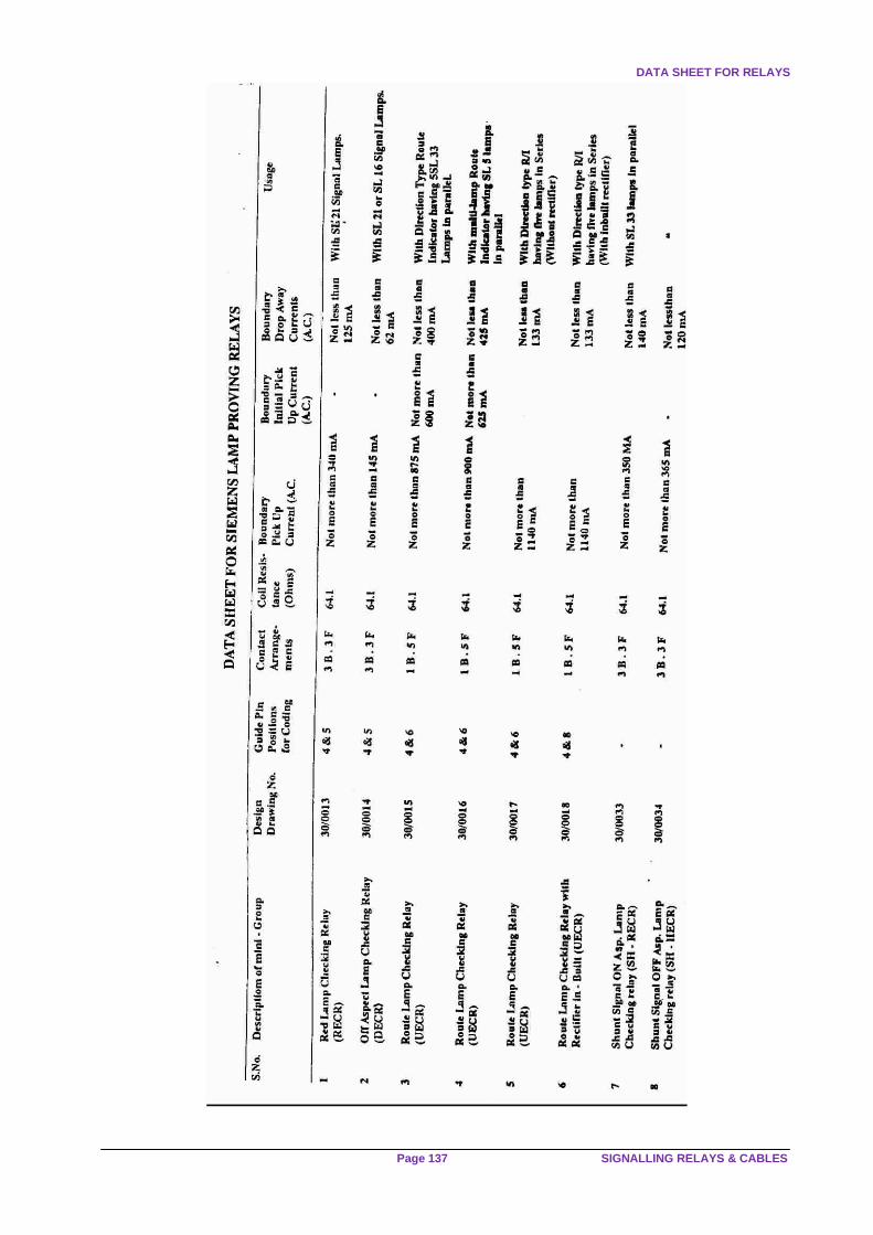
DATA SHEET FOR RELAYS
Page 137 SIGNALLING RELAYS & CABLES

ANNEXURE ‘C’
IRISET Page138

DATA SHEET FOR RELAYS
Page 139 SIGNALLING RELAYS & CABLES

ANNEXURE ‘C’
IRISET Page140

DATA SHEET FOR RELAYS
Page 141 SIGNALLING RELAYS & CABLES