Embed Size (px)
Citation preview

1
THANK YOU,
On behalf of everyone at HYD·MECH Group Limited, we would like to thank and congratulate you on your decision to purchase a HYD·MECH bandsaw.
Your new machine is now ready to play a key role in increasing the efficiency of your operation, helping you to reduce cost while boosting quality and productivity.
To ensure you are maximizing the power and versatility of your new HYD·MECH bandsaw, please take the time tofamiliarize yourself and your employees with the correct operation and maintenance procedures as outlined in thismanual. Please keep this instruction manual for future reference in a known location and easily accessible to all users of the device.
HYD·MECH offers a great variety of options, components, and features for its various models. Therefore, some of the equipment described in this manual (various illustrations and drawings) may not be applicable to your particular machine.
The information and specifications provided in this manual were accurate at the time of printing. HYD·MECH reserves the right to discontinue or change specifications or design at any time without notice and without incurring any obligation.
Thank you.
Hyd·Mech Group LimitedP.O. Box 1659, 1079 Parkinson RoadWoodstock, Ontario, N4S 0A9Phone : (519) 539-6341Service : 1-877-237-0914Sales : 1-877-276-SAWS (7297)Fax : (519) 539-5126e-mail : [email protected]
Printed FEB 2016
S20P393396


i
TABLE OF CONTENTS
SECTION 0 - SAFETY INSTRUCTIONSSUMMARY .......................................................................................................................................0.1BASIC RULES ..................................................................................................................................0.4SAFETY HAZARD LABELS .............................................................................................................0.9
SECTION 1 - INSTALLATIONINSTALLATION ................................................................................................................................1.1SAFETY PRECAUTIONS .................................................................................................................1.1LIFTING THE S20P WITH A FORK LIFT .........................................................................................1.2WRAPPED FOR SHIPPING .............................................................................................................1.2FOUNDATION, LEVELLING AND ANCHORING .............................................................................1.2CUTTING FLUID ..............................................................................................................................1.3HYDRAULIC OIL ..............................................................................................................................1.3WIRING CONNECTIONS .................................................................................................................1.3
SECTION 2 – OPERATING INSTRUCTIONSOPERATOR CONTROL PANEL .......................................................................................................2.1MANUAL MODE MACHINE OPERATION .......................................................................................2.2SETTING HEAD UP AND HEAD DOWN LIMITS .............................................................................2.2CYCLE PARAMETER DISPLAY.......................................................................................................2.3MACHINE ALARMS AND EMERGENCIES .....................................................................................2.4SETTING THE HEAD LINEAR POTENTIOMETER (RHLS/FHLS LIMIT) .......................................2.5MECHANICAL CONTROLS .............................................................................................................2.5HEAD SWING AND BREAK ............................................................................................................2.5COOLANT FLOW .............................................................................................................................2.6GUIDE ARM POSITIONING .............................................................................................................2.6WORK STOP ....................................................................................................................................2.6BLADE BASICS................................................................................................................................2.7
SECTION 3 – MAINTENANCE AND TROUBLESHOOTINGSAFETY DURING MAINTENANCE AND TROUBLESHOOTING ....................................................3.1LOCK OUT PROCEDURE ...............................................................................................................3.1BLADE CHANGING PROCEDURE .................................................................................................3.2BLADE TRACKING ADJUSTMENT .................................................................................................3.4BLADE GUIDE ADJUSTMENT ........................................................................................................3.5CARBIDE REPLACEMENT ..............................................................................................................3.6BLADE PERPENDICULARITY .........................................................................................................3.6BLADE BRUSH ADJUSTMENT .......................................................................................................3.7ANGLE BRAKE ADJUSTMENT .......................................................................................................3.8BLADE TENSION SLIDE ADJUSTMENT ........................................................................................3.990 AND 30 DEGREE STOP ADJUSTMENT ....................................................................................3.9GEARBOX LUBRICATION ...............................................................................................................3.9LUBRICATION .................................................................................................................................3.10
ii
SECTION 4 - ELECTRICALFOR ELECTRICAL SCHEMATICS AND COMPONENTS PARTS LISTS SEE PDF ON ATTACHED CD ....................................................................................................................................................4.1
SECTION 5 - HYDRAULICCYLINDER LIST ...............................................................................................................................5.1FOR HYDRAULIC SCHEMATICS AND PLUMBING DIAGRAMS SEE PDF ON ATTACHED CD.....................................................................................................................................................5.1
SECTION 6 - MECHANICAL ASSEMBLIESFOR MECHANICAL ASSEMBLY DRAWINGS SEE PDF ON ATTACHED CD ................................6.1
SECTION 7 - OPTIONAL EQUIPMENTFOR OPTIONAL ASSEMBLIES SEE PDF ON ATTACHED CD .......................................................7.1MIST COOLANT SYSTEM ...............................................................................................................7.1WORK STOP ASSEMBLY ................................................................................................................7.1WORK LAMP ASSEMBLY ................................................................................................................7.1VARIABLE VISE PRESSURE OPTION ...........................................................................................7.2OVERHEAD BUNDLING ..................................................................................................................7.2
SECTION 8 - SPECIFICATIONSS20P BANDSAW SPECIFICATION LIST .........................................................................................8.1S20P LAYOUT ..................................................................................................................................8.2
SECTION 9 - WARRANTYWARRANTY .....................................................................................................................................9.1
0.1
SECTION 0 - SAFETY INSTRUCTIONSSUMMARY
All persons operating this machine must have read and understood all of the following sections of this Manual:Section 0 SAFETYSection 2 OPERATING INSTRUCTIONS
However, as a memory aid, the following is a summary of the Safety Section.
Put Safety First
Mandatory Information – What operators and maintenance people must have read and understood.
Signatures – Everyone involved with this machine must sign to confirm they have read and understood mandatory infor-mation.
Basic Rules – only use this machine when
• it is in good working order
• all safety equipment is in place and functional
• operations are in compliance with this manual
• materials are within designed specifications and are non-hazardous
Owner is responsible to
• keep Manual accessible at the machine
• ensure only reliable, fully trained personnel work with the machine
• clearly define responsibilities of all personnel working with the machine
• keep the machine in good working order
Operator and Maintenance Personnel are responsible to:
• keep all safety equipment in order, check its function at the beginning of each shift, and report any shortcomings
• shut-down machine and report any faults or malfunctions which could impair safety
• understand and obey safety hazard labels
• not to wear un-restrained long hair, loose clothing or jewelry
• wear all required personal protective equipment
• not to wear gloves within 24 inches of moving blade
• maintain a clean working area and machine
• always use Lock-out when performing maintenance or repairs.
0.2
FOREWORD
Put Safety First!
This Safety Section contains important information to help you work safely with your machine and describes the dangers inherent in our machines. Some of these dangers are obvious, while others are less evident.
It really is important to PUT SAFETY FIRST. Make it a habit to consider the hazards associated with any action BEFORE you do it. If you feel any uncertainty, stop and find a safer approach to the action. If you’re still uncertain, ask for advice from your supervisor.
The SAFETY FIRST approach is particularly necessary when you do something new, or different, and most people in-stinctively recognize this, although impatience may still cause them to take unnecessary risks.
Danger also lurks in the routine task that we have done over and over. Here, familiarity, boredom, or tiredness may lull us into unthinking, automatic repetition. Be alert for this, and when you feel it happening, stop and take stock of your situa-tion. Review the safety hazards associated with what you are doing. That should get your brain working again.
Certainly production is important, but if you think you’re too busy to put safety first, think how much production you’ll lose if you get hurt.
You owe it to yourself, your family, and your co-workers to PUT SAFETY FIRST.
Mandatory Information
All persons operating this machine must have read and understood all of the following sections of this Manual:
Section 0 SAFETY
Section 2 OPERATING INSTRUCTIONS
Personnel involved in installation and maintenance of the machine must have read and understood all sections of the manual
Persons who have difficulty reading, or for whom English is not their first language, must receive particularly thorough instruction.

0.3
Signatures
Everyone involved in operation of this machine must sign below to confirm that:
I have read and understood all parts of Section 0 – Safety, and Section 2 – Operating Instructions.
Name Date Signature
Everyone involved in the installation, inspection, maintenance, and repair of this machine must sign below to confirm that:
I have read and understood all parts of this Operation and Maintenance Manual.
Name Date Signature

0.4
BASIC RULES
Intended Use
Our machines are designed and built in line with the state of the art, and specifically in accordance with American National Standards Institute Standard B11.10 Safety Requirements for Metal Sawing Machines.However, all machines may endanger the safety of their users and/or third parties, and be damaged, or damage other property, if they are operated incorrectly, used beyond their specified capacity, or for purposes other than those specified in this Manual.
Exclusion of Misuse
Misuse includes, for example:
Sawing hazardous materials such as magnesium or lead
Sawing work pieces which exceed the maximum workload appearing in the Specifications
Operating the machine without all original safety equipment and guards
Liability
The machine may only be operated:
When it is in good working order, and
When the operator has read and understood the Safety and Operating Instructions Sections of the Manu-al, and
When all operations and procedures are in compliance with this Manual.
Hyd-Mech Group cannot accept any liability for personal injury or property damage due to operator errors or non-compliance with the Safety and Operating Instructions contained in this Manual.
0.5
Responsibilities of the owner
Organization of work
This Operation and Maintenance Manual must always be kept near the machine so that it is accessible to all concerned.
The general, statutory and other legal regulations on accident prevention and environmental protection must also be observed, in addition to the Manual material. The operators and maintenance personnel must be instructed accordingly. This obligation also includes the handling of dangerous substances and the provision and use of personal protective equipment.
Choice and qualification of personnel
Ensure that work on the machine is only carried out by reliable persons who have been appropriately trained for such work.
Training
Everyone working on or with the machine must be duly trained with regard to the correct use of the ma-chine, the correct use of safety equipment, the foreseeable dangers that may arise during operation of the machine, and the safety precautions to be taken.
In addition, the personnel must be instructed to check all safety devices at regular intervals.
Define responsibilities
Clearly define exactly who is responsible for operating, setting-up, servicing and repairing the machine.
Define the responsibilities of the machine operator and authorize him to refuse any instructions by third parties if they run contrary to the machine’s safety.
Persons being trained on the machine may only work on or with the machine under the constant supervi-sion of an experienced operator. Observe the minimum age limits required by law.
Condition of Machine and Workplace
Ensure that the machine and its safety equipment is kept in good working order.
Ensure that the work area is well lit, and protected from the elements, such as rain, snow, abrasive dust, and extremes of temperature.
Ensure that the machine is installed with sufficient clearance around it for the safe loading and unloading of work pieces.
0.6
Responsibilities of the operator and maintenance personnel
Safety equipment
All machines are delivered with safety equipment that must not be removed or bypassed during operation.
The correct functioning of safety equipment on the machine must be checked:
• at the start of every shift.
• after maintenance and repair work
• when starting for the first time, and after prolonged shutdowns
Emergency Stop Button ( E-Stops)
Always be aware of the location of the Emergency Stop Buttons). Do not allow material or objects to block your access to an Emergency Stop.
Damage
If any changes capable of impairing safety are observed in the machine or its operation, such as damage, malfunctions, or irregularities, then appropriate steps must be taken immediately, the machine switched off, locked-out, and the fault reported to the responsible person.
Safe operation
The machine may only be operated when in good working order and when all protective equipment is in place and operational.
Keep a safe distance from all moving parts – especially the blade and vises
Stock should not be loaded onto the saw if the blade is running
Long and heavy stock should always be properly supported in front of and behind the saw.
Faults
The machine must be switched off and locked-out before starting to remedy any faults.
Safety hazard labels
Safety hazard labels, and other instructional labels on the machine must be observed. They must be clearly visible and legible at all times. If they become damaged they must be replaced.
Clothing, jewelry, protective equipment
Personnel operating or working on the machine must not wear un-restrained long hair, loose-fitting clothes and dangling jewelry.
When operating or working on the machine, always wear suitable, officially tested personal pro-tective equipment such as safety glasses and safety boots and any other equipment required by plant regulations.
0.7
Gloves
Experience has shown that careless use of gloves around machinery is a major factor in serious hand injuries.
Gloves should not be worn when operating or adjusting the machine, except:
Wear protective gloves when handling bandsaw blades at blade changes.
Gloves may be worn when handling work pieces, only if the machine is in Manual Mode and the bandsaw blade is not running.
If the machine is running in Auto Mode, and only if the cut parts are greater than 24 inches long, it may be possible to safely wear gloves for handling the cut parts, but the wearer of the gloves must never put his hands near the blade for any reason. If the cut parts are less than 24 inches long, it is required to arrange their automatic flow into a parts bucket or other suitable arrangement to avoid the necessity to pick them off the machine by hand.
Hearing protection
Ear protection must be worn whenever necessary.
The level and duration of noise emission requiring hearing protection depends upon the national regulations in the country in which the machine is being used.
The actual level of noise emission by band sawing machines depends upon work piece size, shape and material, blade type, blade speed and feed rate.
The only practical course of action is to measure the actual noise emission levels for the type of work that is typically done. With reference to national standards, decide upon the necessary hearing protection required.
In the absence of such measurements, it is advisable for anyone exposed to long periods of moderate to loud noise to wear hearing protection. It is important to understand that hearing loss is gradual and easily goes unnoticed until it is serious and irreversible.
Workplace
A clear working area without any obstructions is essential for safe operation of the machine. The floor must be level and clean, without any build-up of chips, off-cuts, coolant, or hydraulic oil.
The workplace must be well lit, and protected from the elements, such as rain, snow, abrasive dust, and extremes of temperature
Nothing may ever be placed on, or leaned against the machine, with the obvious exception of the work piece on the table and conveyor of the machine.

0.8
Master Disconnect
Lock-out the machine before undertaking any maintenance or repair work on it. ‘Lock-out’ refers switching off the master electrical disconnect switch, and locking it out so that it cannot be switched on again without authorization.
On Hyd-Mech machines the Master Disconnect Switch will be of one of three types:
• Rotary switch mounted in electrical control cabinet door and inter-locked with door
• Lever switch mounted in separate box mounted on the machine
• Supply disconnect switch supplied by user at installation and usually wall-mounted within sight of the machine, depending upon local regulations.
In almost all jurisdictions, it is required that owners of industrial equipment establish and post lock-out pro-cedures. Know and use the lock-out procedures of your company or organization.
Residual Risks
The machine is still not completely de-energized if an electrical cabinet door type switch is locked-out.
The line side of the disconnect switch itself remains energized.
Variable speed blade drives store dangerous voltage in their capacitors, and this requires time to dissipate. After locking out power, wait 3 minutes before beginning to work on machine electrical circuits.
If compressed air is supplied to the machine to power a mist lubrication system or other devices, it should be disconnected, and any stored air pressure released before working on the machine.
The weight of individual machine components represents stored potential energy that can be released if they fall when disconnected. Secure these components with adequate hoisting gear before disassembly.
0.9
SAFETY HAZARD LABELS
The safety hazard labels attached to your machine represent important safety information to help you avoid personal injury or death.All supervisors, operators, and maintenance personnel must locate and understand the safety information associated with each hazard label prior to operating or servicing the machine.The safety hazard labels shown below are located at various positions on the machine to indicate possible safety hazards. The location, and re-order part number of all the safety labels associated with this particular model of bandsaw are indicated at the end of this section of the manual. It is important to replace any safety hazard label that becomes damaged or illegible.
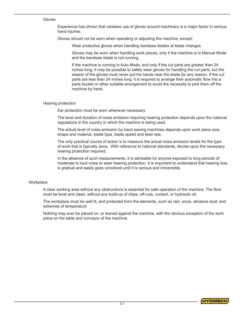
MOVING BANDSAW BLADE WILL CUT
Do NOT operate with guard removed.Do NOT place hands or fingers near moving bandsaw blade.For blade changing, always follow the proper Blade Changing Procedure, as given in Section 3 of this manual.
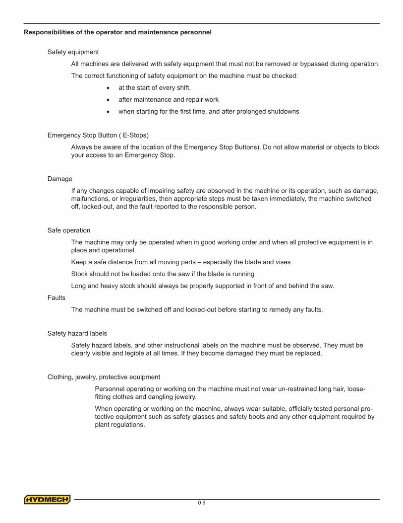
HAZARDOUS VOLTAGE INSIDE
Contact with high voltage may cause death or serious injury. Never perform maintenance on, or near, electrical components until the machine’s electrical power source has been disconnected. Lock-out power in accordance with your company’s lock-out procedures before any such maintenance. The “Stop” or “Emergency Stop” push button does not disconnect the machine’s power supply. Hazardous voltage is still present in the machines electrical circuits.The machine’s Electrical Disconnect Switch does disconnect voltage from the machine’s circuits, however hazardous voltage is still present inside the main
electrical cabinet, on the infeed (line) side of the main fuses. Therefore keep hands and tools away from the infeed side of the control panel main fuses. If these fuses need to be replaced, use a fuse puller.Allow three minutes after locking-out power before opening any electrical enclosures. Your machine may be equipped with a variable frequency drive that stores high voltage within its capacitors. Three minutes will allow sufficient time for this voltage to safely discharge.Never spray coolant directly at electrical components or cabinets.
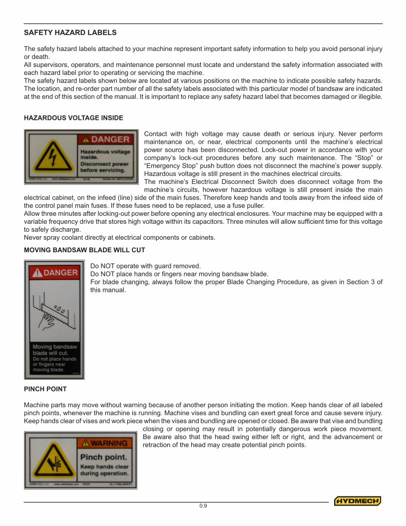
PINCH POINT
Machine parts may move without warning because of another person initiating the motion. Keep hands clear of all labeled pinch points, whenever the machine is running. Machine vises and bundling can exert great force and cause severe injury. Keep hands clear of vises and work piece when the vises and bundling are opened or closed. Be aware that vise and bundling
closing or opening may result in potentially dangerous work piece movement. Be aware also that the head swing either left or right, and the advancement or retraction of the head may create potential pinch points.
0.10
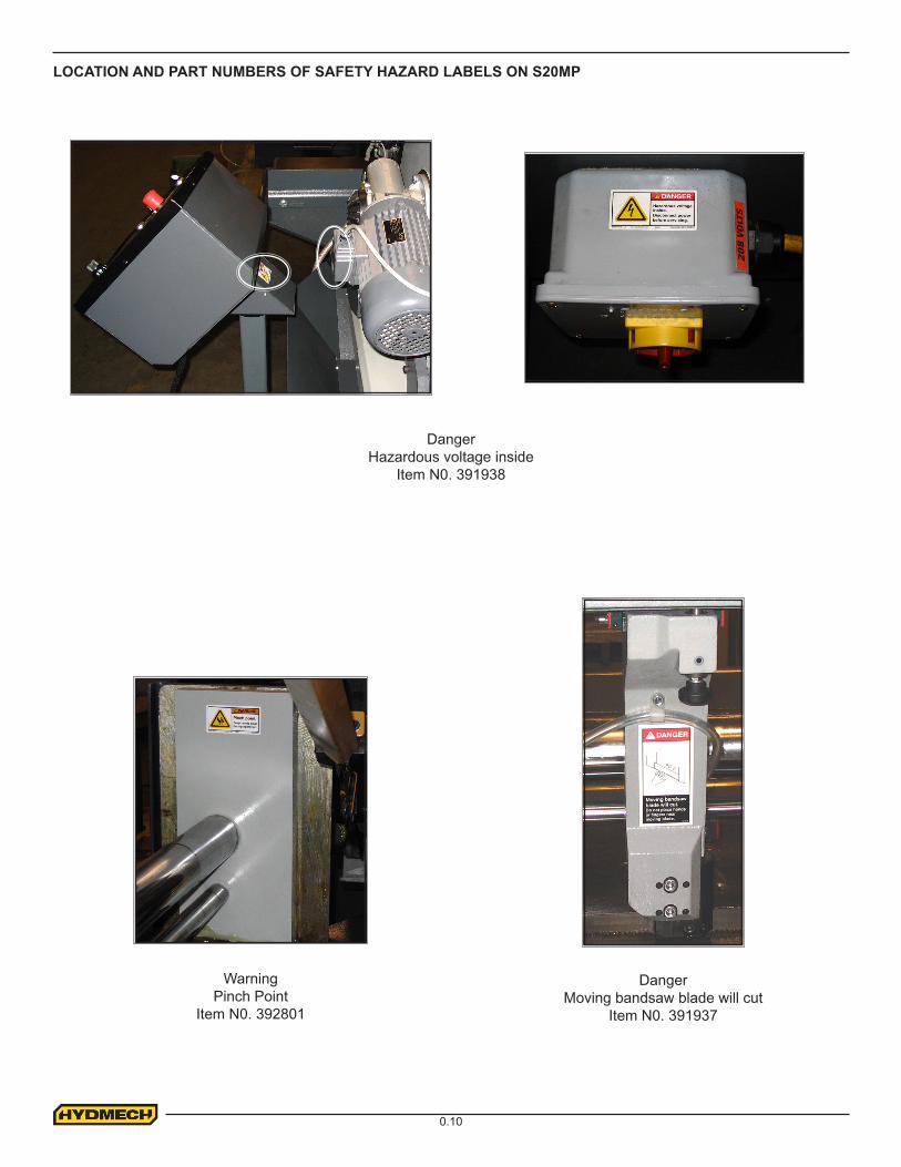
LOCATION AND PART NUMBERS OF SAFETY HAZARD LABELS ON S20MP
WarningPinch Point
Item N0. 392801
DangerMoving bandsaw blade will cut
Item N0. 391937
DangerHazardous voltage inside
Item N0. 391938

1.1
INSTALLATION
Upon delivery of your new S20P saw, it is imperative that a thorough inspection be undertaken to check for any damage that could have been sustained during shipping. Special attention should be paid to the electrical and hydraulic systems to check for damaged cords, hoses and fluid leaks. In the event of damage caused during shipping, contact your carrier to file a damage claim.
SAFETY PRECAUTIONS
The S20P has been designed to give years of reliable service. It is essential that operators be alerted to the safe opera-tion of this saw, and the practices to avoid that could lead to injury. The following safety rules are at the minimum neces-sary for the safe installation, operation, and maintenance of the saw. Take every precaution for the protection of operators and maintenance personnel.
• POWER HOOK-UPS AND REPAIRS SHOULD BE ATTEMPTED ONLY BY QUALIFIED TRADESMEN.
• THE SAW SHOULD BE LOCATED IN AN AREA WITH SUFFICIENT ROOM TO SAFELY LOAD STOCK INTO THE SAW. SECURE THE SAW TO THE FLOOR.
• THE AREA AROUND THE SAW SHOULD BE MAINTAINED IN A CLEAN AND TIDY CONDITION TO AVOID OBSTACLES OPERATORS COULD TRIP OVER.
• THE S20P SHOULD ONLY BE OPERATED ACCORDING TO THE SPECIFICATIONS OF THE SAW. AVOID UNSAFE USAGE PRACTICES.
• IF AT ANY TIME THE SAW DOES NOT APPEAR TO BE OPERATING PROPERLY IT SHOULD BE STOPPED IMMEDIATELY AND REPAIRED.
OPERATOR:
• THE SAW SHOULD NEVER BE OPERATED UNLESS ALL GUARDS AND DOORS ARE IN PLACE AND CLOSED.
• KEEP A SAFE DISTANCE FROM ALL MOVING PARTS - ESPECIALLY THE BLADE AND VISES.
• LOOSE CLOTHING AND GLOVES SHOULD NEVER BE WORN WHILE OPERATING THE SAW. COVER LONG HAIR.
• STOCK SHOULD NOT BE LOADED ONTO THE SAW IF THE BLADE IS RUNNING.
• LONG AND HEAVY STOCK SHOULD ALWAYS BE PROPERLY SUPPORTED IN FRONT OF AND BEHIND THE SAW.
• NEVER ATTEMPT TO DISLODGE OR MOVE STOCK WHILE THE BLADE IS MOVING. TAKE THE TIME TO STOP THE SAW BLADE, REMOVE OBSTRUCTIONS, AND RESTART BLADE.
• MUST WEAR EYE PROTECTION
• MAINTAIN PROPER ADJUSTMENT OF BLADE TENSION, AND BLADE GUIDES
• HOLD WORK PIECE FIRMLY AGAINST TABLE
• DO NOT REMOVE JAMMED CUTOFF PIECES UNTIL BLADE HAS STOPPED
NO MODIFICATIONS TO THE MACHINE ARE PERMITTED WITHOUT PRIOR APPROVAL FROM HYD-MECH. ANY APPROVED MODIFICATIONS SHOULD ONLY BE UNDERTAKEN BY TRAINED PERSONNEL.
SECTION 1 - INSTALLATION
1.2
LIFTING THE S20P WITH A FORK LIFT
The S20P is shipped with a shipping pallet attached to the saw. When lifting the pallet with a forklift truck make sure that the load is firmly balanced. Minimum fork length of 72" (1827 mm) is recommended to safely lift the pallet.
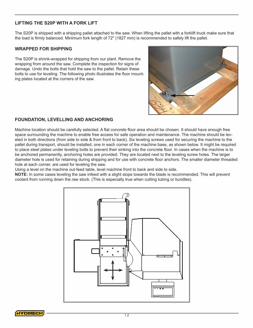
WRAPPED FOR SHIPPING
The S20P is shrink-wrapped for shipping from our plant. Remove the wrapping from around the saw. Complete the inspection for signs of damage. Undo the bolts that hold the saw to the pallet. Retain these bolts to use for leveling. The following photo illustrates the floor mount-ing plates located at the corners of the saw.
FOUNDATION, LEVELLING AND ANCHORING
Machine location should be carefully selected. A flat concrete floor area should be chosen. It should have enough free space surrounding the machine to enable free access for safe operation and maintenance. The machine should be lev-eled in both directions (from side to side & from front to back). Six leveling screws used for securing the machine to the pallet during transport, should be installed, one in each corner of the machine base, as shown below. It might be required to place steel plates under leveling bolts to prevent their sinking into the concrete floor. In cases when the machine is to be anchored permanently, anchoring holes are provided. They are located next to the leveling screw holes. The larger diameter hole is used for retaining during shipping and for use with concrete floor anchors. The smaller diameter threaded hole at each corner, are used for leveling the saw.Using a level on the machine out-feed table, level machine front to back and side to side.NOTE: In some cases leveling the saw infeed with a slight slope towards the blade is recommended. This will prevent coolant from running down the raw stock. (This is especially true when cutting tubing or bundles).
1.3
WIRING CONNECTIONS
After the machine is leveled and anchored the necessary power hook-up needs to be performed.Check that there is no sign of shipping damage to the electrical conduits, cords or hydraulic hoses.
As supplied, the S20P is built to run on three phase AC Voltage, as indicated on the machine serial plate and voltage label. Machine voltage is customer specific and should be indicated while ordering the machine. If machine voltage does not match available power source contact factory.
Power connection to the machine is made in the junction box, located on the back side of the machine. The power cable can be routed through the supplied hole in the junction box, and connections made to L1, L2, L3, and ground terminals. Proper strain relief should be used on the incoming power cable.
CUTTING FLUID
The S20P uses a pump and reservoir to circulate the necessary cutting fluid to the blade for maximum blade life. Your saw blade supplier will be able to provide information to the cutting fluid products that are available for your needs.
No cutting fluid (coolant) is supplied with the machine. There are two types of coolant available:
- Oil based; dilute 1:10 ratio (one part concentrated coolant to 10 parts water) - Synthetic; dilute as recommended by manufacturer.
HYDRAULIC OIL
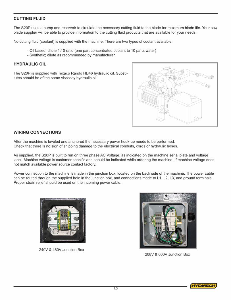
The S20P is supplied with Texaco Rando HD46 hydraulic oil. Substi-tutes should be of the same viscosity hydraulic oil.
240V & 480V Junction Box208V & 600V Junction Box
2.1
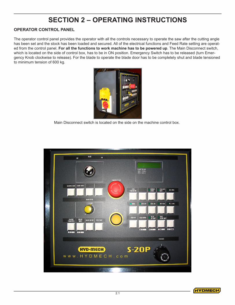
SECTION 2 – OPERATING INSTRUCTIONSOPERATOR CONTROL PANEL
The operator control panel provides the operator with all the controls necessary to operate the saw after the cutting angle has been set and the stock has been loaded and secured. All of the electrical functions and Feed Rate setting are operat-ed from the control panel. For all the functions to work machine has to be powered up. The Main Disconnect switch, which is located on the side of control box, has to be in ON position. Emergency Switch has to be released (turn Emer-gency Knob clockwise to release). For the blade to operate the blade door has to be completely shut and blade tensioned to minimum tension of 600 kg.
Main Disconnect switch is located on the side on the machine control box.

2.2
Manual Mode Machine Operation
Manual mode allows for a manual operation of the saw. In this mode all functions are activated be selection of the respec-tive function button on the user interface.
To enter the manual mode after the main power has been turned off, press the Machine Start button. Follow the instruc-tions on the display, and select the Manual Mode. A lit LED adjacent to the Manual Mode or Semi-Automatic Mode button indicates machine mode.
Cut in Manual Mode
1 Open vise2 Raise head3 Position material4 Close vise5 Start blade6 Press Cycle Start. To pause the head feed press Cycle Pause. To resume head feed press Cycle Start.7 Machine will shut off blade when head reaches downward most position.8 Raise head9 Open vise
Semi-Automatic Mode Machine Operation
Upon initial power up, press MACHINE START. You will be prompted to press the reset button. Follow the onscreen in-structions.
1 Set the HEAD UP and HEAD DOWN LIMITS. Refer to Setting Head Up and Head Down Limits.2 Open vise by pressing the VISE OPEN button.3 Position material.4 Close the vise by pressing the VISE CLOSE button.5 Start the blade by pressing the BLADE ON/OFF button.6 Start the cycle by pressing the CYCLE START button.
The machine will automatically close the vise and proceed to advance the head. Upon reaching the head down limit, which under most operating conditions should be set to the bottom most travel of the head. The blade will turn off, the head will go up to the preset head up limit and the vise will open. Subsequent cuts from the same material may be made by repeating step 3 through 6.
Setting Head Up and Head Down Limits
The machine can be setup to restrict the head movement in Semi-Auto mode between bottom and top limit settings. During normal operating conditions where a complete through cut is required, the head down limit should be set to the bottom most position of the head travel. Setting the head down limit at any other position will result in a partially cut piece. The head up limit should be set according to the material height. In cycle mode the head will respect these two preset limits.
To Set Head Down Limit
- Position the head at the desired head down position by pressing the HEAD UP or HEAD DOWN buttons.
- Press the HEAD DOWN LIMIT button.
To Set Head Up Limit
- Position the head at the desired head up position by pressing the HEAD UP or HEAD DOWN buttons.
- Press the HEAD UP LIMIT button.

2.3
Cycle Parameter Display
The machine is capable of displaying many parameters, not all of which can be shown on the screen at the same time. Pressing the CYCLE PARAMETERS button will toggle the display of the parameters. The following is a list of available parameters and the corresponding abbreviations as they are shown on the display.
Blade speed BSCut time CTBlade tension BTHead position HPAmp draw of blade motor IBMPieces cut PC (To reset press COUNT RESET button)Total run time of blade motor TOTALIZ
Machine Parameters
Machine parameters control the behavior of the machine, the type of optional equipment, which may be installed, and the language in which to communicate with the operator. Modifying machine parameters may adversely effect the behavior of the machine. Prior to making changes care should be taken to ensure a complete understanding of each parameter and its effect on the operation of the saw.
To enter machine parameters toggle the main power off and on. Press the MACHINE PARAMETERS AND MACHINE START buttons in that order.
To move from parameter to parameter press the HEAD DOWN or HEAD UP LIMIT button. Notice the horizontal arrows under the button depicting forward or backward scroll thought the parameter list. To change the value of a parameter use the HEAD DOWN LIMIT button. Notice an up arrow under the button depicting an upward change in value. The button to the right of the HEAD DOWN LIMIT clears the parameter value.

2.4
MACHINE ALARMS AND EMERGENCIESThe machine’s controller notifies the operator if any alarm or emergency condition which may occur during operation by way of acoustic and visual signals. This section lists the message shown on the display.
PRESS RESETThis message is displayed during the initialization phase after pressing the MACHINE START key.
PRESS RESETFCTI-FCTA ERROR
This message is displayed when the cutting start position is lower than the previously set head down position.Save both the FCTI (head up) and FCTA (head down) positions again.
PRESS RESETHEAD NOT AT FCTI
This message is displayed if the head is not positioned at the FCTI, position when the cycle is STARTED.Return the head to the FCTI (head up) position before resuming the cycle.
PRESS RESETSELECT SPEED
This message is displayed if the cycle is STARTED without having first selected the cutting speed.Return the head to the FCTI (head up) position before resuming the cycle.
PARAMETER DESCRIPTION FACTORY SET VALUELANGUAGE Language which will be displayed on the interface English
MACHINE TYPE Machine type S 20 P
MAN & SAD CYCLE Manual and semi automatic YES
PEDAL START Pedal start option NO
INVERTER Inverted blade motor drive YES
BLADE SPEED PROXY Machine equipped with blade speed proximity switch YES
MINIMAL LUBRIF Machine equipped with low level lubricant sensor for mist coolant NO
RHLS/FHLS OUTSHead down / head up outputs enabled. Allows for control board to supply output signal for respective head position.
NO
STOP BLADE MOTOR NVR/RHLS/FHLS
Controls when the blade motor is to stop. Values of the parameter are 0 for when the head is in down limit, 1 for when the head is in up position and 2 for never.
0
HEAD VISE OPEN RHLS/FHLS
Controls when to open vise. Values of parameter are 0 for down limit and 1 for up limit. 0
VISE OPEN/CLOSE TIME = Vise open dwell time. 2.0
MAX BLADE MOTOR I =
Full load amperage of the blade motor. (Depends on voltage of machine) 8.0
UNIT OF MEASURE FIPS/MKS
Controls which unit system to display. 1 for imperial, 0 for metric. 0
BLADE MIN TENS THRES = Minimum blade tension required for the machine to start. 600 kg (1320 lbs)
LCD BACKLIGHT DURATION Time duration of display backlight to stay on min. 0.5
TT = Total time blade motor run. Software version. Value depending on run time.
RHLS / FHLS LIMIT HEAD POS =
Head position - SEE PROCEDURE - SETTING the HEAD LINEAR POTENTIOMETER (RHLS/FHLS LIMIT)
Value depending on head position.
2.5
MECHANICAL CONTROLS
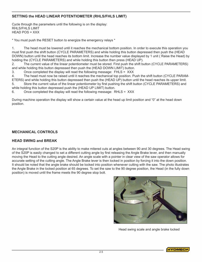
HEAD SWING and BREAK
An integral function of the S20P is the ability to make mitered cuts at angles between 90 and 30 degrees. The Head swing of the S20P is easily changed to set a different cutting angle by first releasing the Angle Brake lever, and then manually moving the Head to the cutting angle desired. An angle scale with a pointer in clear view of the saw operator allows for accurate setting of the cutting angle. The Angle Brake lever is then locked in position by forcing it into the down position. It should be noted that the angle brake should be locked into position whenever cutting with the saw. The photo illustrates the Angle Brake in the locked position at 65 degrees. To set the saw to the 90 degree position, the Head (in the fully down position) is moved until the frame meets the 90 degree stop bolt.
Head swing scale and angle brake locked
SETTING the HEAD LINEAR POTENTIOMETER (RHLS/FHLS LIMIT)
Cycle through the parameters until the following is on the display:RHLS/FHLS LIMITHEAD POS = XXX
* You must push the RESET button to energize the emergency relays *
1. The head must be lowered until it reaches the mechanical bottom position. In order to execute this operation you must first push the shift button (CYCLE PARAMETERS) and while holding this button depressed then push the (HEAD DOWN) button until the head reaches its bottom limit. Increase the number value displayed by 1 unit ( Raise the Head) by holding the (CYCLE PARAMETERS) and while holding this button then press (HEAD UP).2. The current value of the linear potentiometer must be stored. First push the shift button (CYCLE PARAMETERS) and while holding this button depressed then push the (HEAD DOWN LIMIT) button.3. Once completed the display will read the following message: FHLS = XXX4. The head must now be raised until it reaches the mechanical top position. Push the shift button (CYCLE PARAM-ETERS) and while holding this button depressed then push the (HEAD UP) button until the head reaches its upper limit.5. Store the current value of the linear potentiometer by first pushing the shift button (CYCLE PARAMETERS) and while holding this button depressed push the (HEAD UP LIMIT) button. 6. Once completed the display will read the following message: RHLS = XXX
During machine operation the display will show a certain value at the head up limit position and “0” at the head down position.
2.6
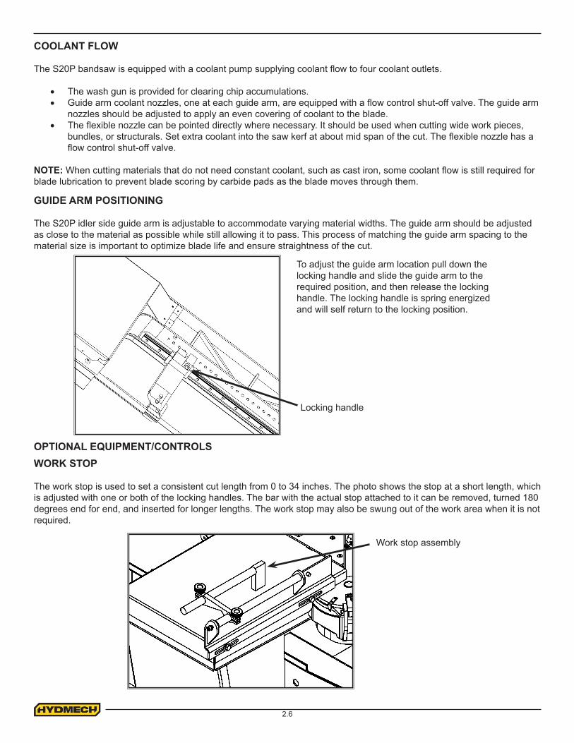
Work stop assembly
WORK STOP The work stop is used to set a consistent cut length from 0 to 34 inches. The photo shows the stop at a short length, which is adjusted with one or both of the locking handles. The bar with the actual stop attached to it can be removed, turned 180 degrees end for end, and inserted for longer lengths. The work stop may also be swung out of the work area when it is not required.
OPTIONAL EQUIPMENT/CONTROLS
GUIDE ARM POSITIONING
The S20P idler side guide arm is adjustable to accommodate varying material widths. The guide arm should be adjusted as close to the material as possible while still allowing it to pass. This process of matching the guide arm spacing to the material size is important to optimize blade life and ensure straightness of the cut.
To adjust the guide arm location pull down the locking handle and slide the guide arm to the required position, and then release the locking handle. The locking handle is spring energized and will self return to the locking position.
Locking handle
COOLANT FLOW
The S20P bandsaw is equipped with a coolant pump supplying coolant flow to four coolant outlets.
• The wash gun is provided for clearing chip accumulations.• Guide arm coolant nozzles, one at each guide arm, are equipped with a flow control shut-off valve. The guide arm
nozzles should be adjusted to apply an even covering of coolant to the blade. • The flexible nozzle can be pointed directly where necessary. It should be used when cutting wide work pieces,
bundles, or structurals. Set extra coolant into the saw kerf at about mid span of the cut. The flexible nozzle has a flow control shut-off valve.
NOTE: When cutting materials that do not need constant coolant, such as cast iron, some coolant flow is still required for blade lubrication to prevent blade scoring by carbide pads as the blade moves through them.
2.7
5. The proper feed rate must be applied. Feed rate is the speed which the head “free-falls” and is set with the feed rate control knob. The head will descend more slowly when the blade encounters the work-piece. Verification of proper feed rate is provided by the appearance of the cut chips, which ideally form nicely curled “clock springs”. Note that cast irons and interrupted cuts result in short, broken chips even at ideal feed rates. Excessive feed rate will result in short blade life and/or crooked cuts.
BLADE BASICS
Technology is rapidly changing all aspects of production machining. Metal cutoff is no exception. The advances made in the bandsaw industry have definitely brought down the cost per cut, despite the three-fold increase in the price of newer technology blades. Variable pitch (following pages), bi-metal blades (like the ¾ or 4/6 bi-metal blade supplied with the Hyd-Mech machine) last much longer, cut faster and more accurately than the conventional carbon steel blades. In order to take advantage of the superiority of bi-metal blades, it is critical to properly “break in” a new blade. This is accomplished by taking two or three cuts through solid four or five-inch diameter mild steel at an extremely slow feed rate. These two or three slow cuts sufficiently lap (polish) the new blade so that it does not snag the material being cut. Proper break-in will alleviate blade vibration, improve surface finish and accuracy, and improve expected blade life.
1. A new blade must be properly “broken-in”. Proper break-in will alleviate blade vibration, improve surface finish and accuracy, and improve expected blade life. The most convenient way to do this is to cut the intended work-piece, at the standard recommended blade speed for that material, but with the feed rate reduced to about 25% of normal. Near the end of the first cut, increase the feed rate again, and once again when the blade approaches the end of the second cut. Keep increasing feed rate in this fashion, so that normal feed rate is reached after 300 to 400 square centimeters of cutting.
2. Generous coolant application is essential with almost all materials. A high quality and well-mixed coolant will dramatically extend blade life, and will increase cutting rate and surface finish. On those few materials where cool-ant is undesirable, a slight coolant flow or periodic oiling of the blade is necessary to prevent the blade from being scored by the carbide guides.
3. The Stock being cut must be securely clamped in the vises. Stock movement during cutting will strip blade teeth. Noticeable stock vibration reduces cutting performance and blade life – consideration should be given to reorientation of the stock, or additional clamping measures (e.g. wood between vise jaws and work-piece).
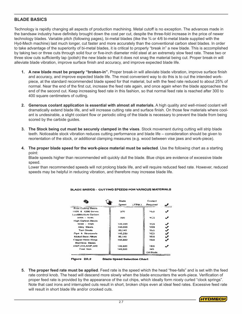
4. The proper blade speed for the work-piece material must be selected. Use the following chart as a starting point:Blade speeds higher than recommended will quickly dull the blade. Blue chips are evidence of excessive blade speed.Lower than recommended speeds will not prolong blade life, and will require reduced feed rate. However, reduced speeds may be helpful in reducing vibration, and therefore may increase blade life.
2.8
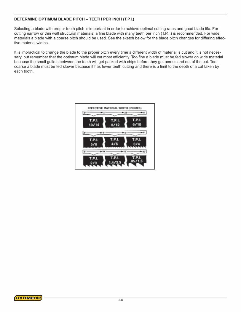
DETERMINE OPTIMUM BLADE PITCH – TEETH PER INCH (T.P.I.)
Selecting a blade with proper tooth pitch is important in order to achieve optimal cutting rates and good blade life. For cutting narrow or thin wall structural materials, a fine blade with many teeth per inch (T.P.I.) is recommended. For wide materials a blade with a coarse pitch should be used. See the sketch below for the blade pitch changes for differing effec-tive material widths.
It is impractical to change the blade to the proper pitch every time a different width of material is cut and it is not neces-sary, but remember that the optimum blade will cut most efficiently. Too fine a blade must be fed slower on wide material because the small gullets between the teeth will get packed with chips before they get across and out of the cut. Too coarse a blade must be fed slower because it has fewer teeth cutting and there is a limit to the depth of a cut taken by each tooth.
3.1
SECTION 3 – MAINTENANCE AND TROUBLESHOOTINGSAFETY DURING MAINTENANCE AND TROUBLESHOOTING
“Lock-out”, or “Lock-out Tag-out” are terms that refer to procedures taken to prevent the unexpected start-up, or other re-lease of energy, by a machine, whenever anyone is required to remove or bypass safety guards or devices, or whenever anyone is required to place part of his body in a hazard area.In almost all jurisdictions, it is required that owners of industrial equipment establish and post lock-out procedures. Know and use the lock-out procedures of your company or organization. In the absence, of such posted procedures, use the following procedure.
LOCK OUT PROCEDURE
Whenever work is to be performed on a machine, which requires removal or bypassing of safety guards or devices, or the placement of part of anyone’s body in a hazard area, the following steps shall be taken:
1. Operator shuts down the machine. The head must be lowered fully, or onto suitable supports, before any hydraulic service is performed, to prevent the head from moving unexpectedly.
2. The supervisor in charge of the machine must be informed of the intention to Lock-out the machine.3. The Main Power Disconnect Switch must be turned off, and locked in the off position by means of a padlock.
The key for this padlock must be kept by the person performing the work on the machine. If more than one person is performing work on the machine, then a multiple lock hasp shall be used, and each person shall apply his or her own lock to the hasp.
4. Prior to starting any work on the locked-out machine, the supervisor shall attempt to start the machine to ensure that the lock-out device provides adequate protection. Operating controls must be reset to the “off” position after this test.
5. Work on the locked-out machine may now proceed.
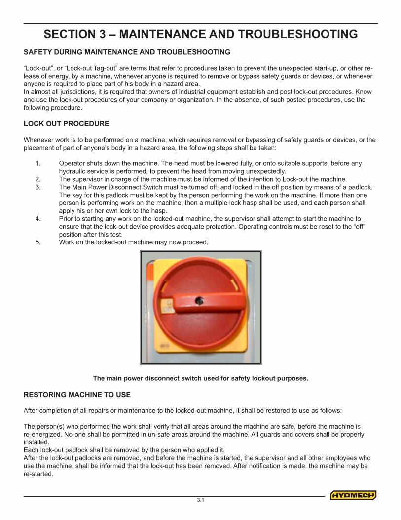
The main power disconnect switch used for safety lockout purposes.
RESTORING MACHINE TO USE
After completion of all repairs or maintenance to the locked-out machine, it shall be restored to use as follows:
The person(s) who performed the work shall verify that all areas around the machine are safe, before the machine is re-energized. No-one shall be permitted in un-safe areas around the machine. All guards and covers shall be properly installed.Each lock-out padlock shall be removed by the person who applied it.After the lock-out padlocks are removed, and before the machine is started, the supervisor and all other employees who use the machine, shall be informed that the lock-out has been removed. After notification is made, the machine may be re-started.
3.2
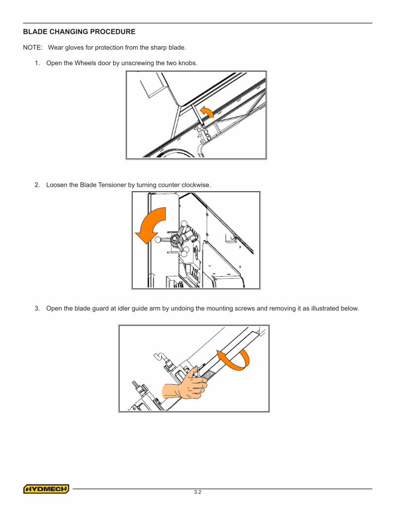
BLADE CHANGING PROCEDURE
NOTE: Wear gloves for protection from the sharp blade.
1. Open the Wheels door by unscrewing the two knobs.
2. Loosen the Blade Tensioner by turning counter clockwise.
3. Open the blade guard at idler guide arm by undoing the mounting screws and removing it as illustrated below.
3.3
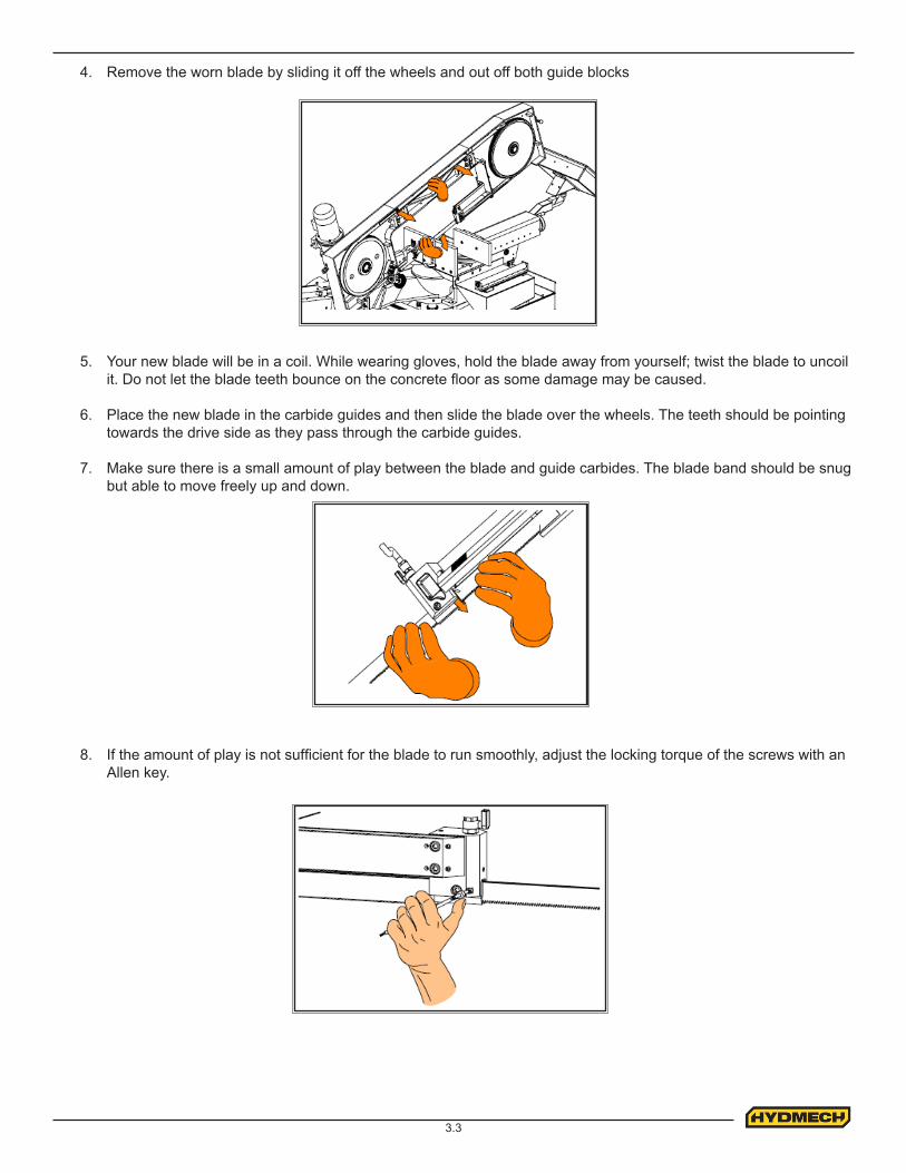
4. Remove the worn blade by sliding it off the wheels and out off both guide blocks
5. Your new blade will be in a coil. While wearing gloves, hold the blade away from yourself; twist the blade to uncoil it. Do not let the blade teeth bounce on the concrete floor as some damage may be caused.
6. Place the new blade in the carbide guides and then slide the blade over the wheels. The teeth should be pointing towards the drive side as they pass through the carbide guides.
7. Make sure there is a small amount of play between the blade and guide carbides. The blade band should be snug but able to move freely up and down.
8. If the amount of play is not sufficient for the blade to run smoothly, adjust the locking torque of the screws with an Allen key.
3.4
9. With the blade in place, turn the tensioner handle clockwise until Bade Tension Display shows required value. Recommended blade tension is between 1250 - 1350 kg. If blade is under tensioned the blade motor will not start.
10. Replace the blade cover and close wheels door.
11. Jog the blade a few rotations to check that the blade is not moving in or out on the blade wheels. As the blade tracking will stay fairly constant, it should be checked occasionally by measuring the gap between the back of the blade and wheel flange. The gap should measure .040-.080”. If the tracking requires adjustment, follow the instructions below.
BLADE TRACKING ADJUSTMENT
First, inspect the blade wheels for wear or damage and repair as required, Blade tracking adjustment should always begin at the wheel where the tracking is farthest out of specification. Using the instructions below, adjust the worst wheel, jog the blade and recheck both wheels. Repeat this process until both wheels are within specification.
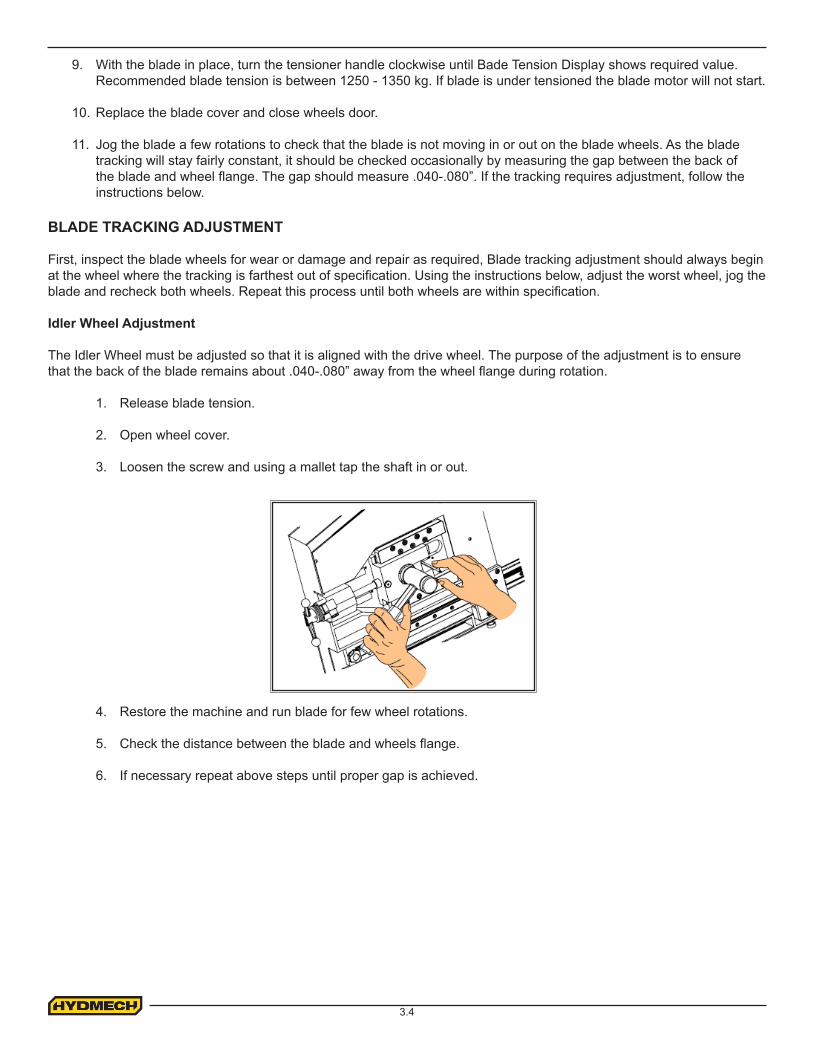
Idler Wheel Adjustment
The Idler Wheel must be adjusted so that it is aligned with the drive wheel. The purpose of the adjustment is to ensure that the back of the blade remains about .040-.080” away from the wheel flange during rotation.
1. Release blade tension.
2. Open wheel cover.
3. Loosen the screw and using a mallet tap the shaft in or out.
4. Restore the machine and run blade for few wheel rotations.
5. Check the distance between the blade and wheels flange.
6. If necessary repeat above steps until proper gap is achieved.
3.5
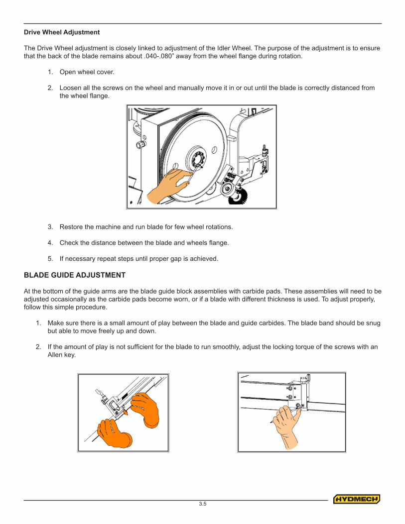
Drive Wheel Adjustment
The Drive Wheel adjustment is closely linked to adjustment of the Idler Wheel. The purpose of the adjustment is to ensure that the back of the blade remains about .040-.080” away from the wheel flange during rotation.
1. Open wheel cover.
2. Loosen all the screws on the wheel and manually move it in or out until the blade is correctly distanced from the wheel flange.
3. Restore the machine and run blade for few wheel rotations.
4. Check the distance between the blade and wheels flange.
5. If necessary repeat steps until proper gap is achieved.
BLADE GUIDE ADJUSTMENT
At the bottom of the guide arms are the blade guide block assemblies with carbide pads. These assemblies will need to be adjusted occasionally as the carbide pads become worn, or if a blade with different thickness is used. To adjust properly, follow this simple procedure.
1. Make sure there is a small amount of play between the blade and guide carbides. The blade band should be snug but able to move freely up and down.
2. If the amount of play is not sufficient for the blade to run smoothly, adjust the locking torque of the screws with an Allen key.
3.6
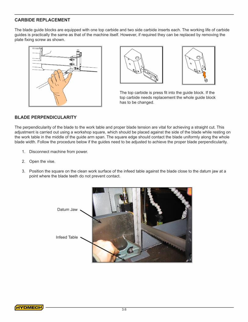
CARBIDE REPLACEMENT
The blade guide blocks are equipped with one top carbide and two side carbide inserts each. The working life of carbide guides is practically the same as that of the machine itself. However, if required they can be replaced by removing the plate fixing screw as shown.
BLADE PERPENDICULARITY
The perpendicularity of the blade to the work table and proper blade tension are vital for achieving a straight cut. This adjustment is carried out using a workshop square, which should be placed against the side of the blade while resting on the work table in the middle of the guide arm span. The square edge should contact the blade uniformly along the whole blade width. Follow the procedure below if the guides need to be adjusted to achieve the proper blade perpendicularity.
1. Disconnect machine from power.
2. Open the vise.
3. Position the square on the clean work surface of the infeed table against the blade close to the datum jaw at a point where the blade teeth do not prevent contact.
The top carbide is press fit into the guide block. If the top carbide needs replacement the whole guide block has to be changed.
Datum Jaw
Infeed Table
3.7
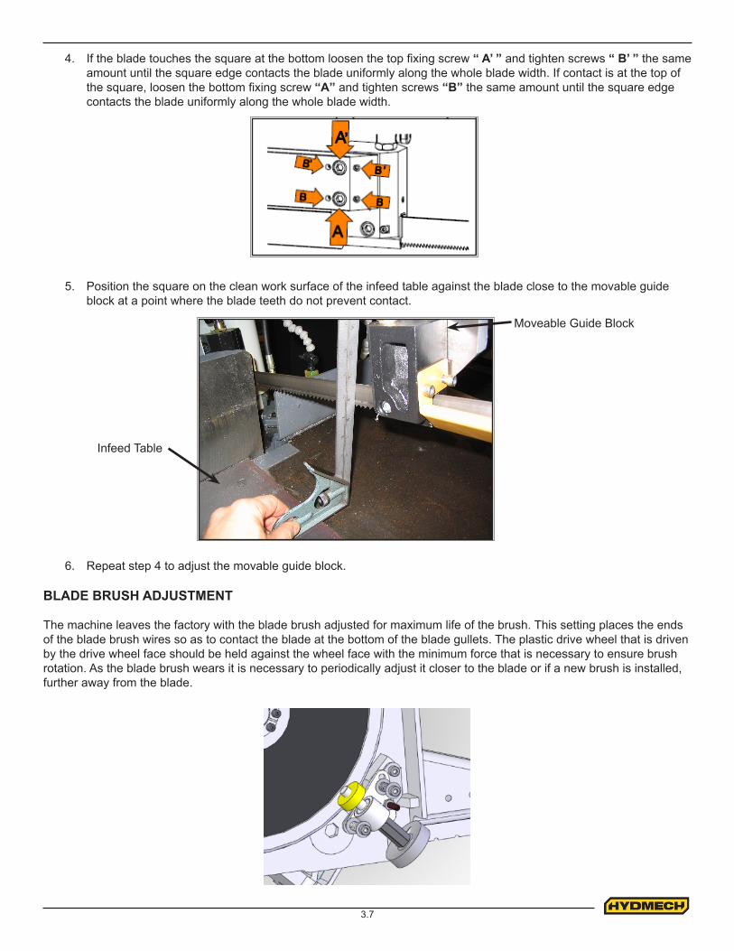
4. If the blade touches the square at the bottom loosen the top fixing screw “ A’ ” and tighten screws “ B’ ” the same amount until the square edge contacts the blade uniformly along the whole blade width. If contact is at the top of the square, loosen the bottom fixing screw “A” and tighten screws “B” the same amount until the square edge contacts the blade uniformly along the whole blade width.
5. Position the square on the clean work surface of the infeed table against the blade close to the movable guide block at a point where the blade teeth do not prevent contact.
6. Repeat step 4 to adjust the movable guide block.
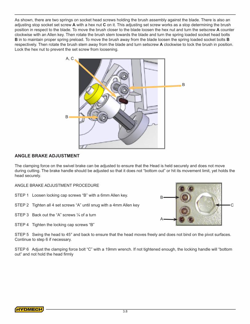
BLADE BRUSH ADJUSTMENT
The machine leaves the factory with the blade brush adjusted for maximum life of the brush. This setting places the ends of the blade brush wires so as to contact the blade at the bottom of the blade gullets. The plastic drive wheel that is driven by the drive wheel face should be held against the wheel face with the minimum force that is necessary to ensure brush rotation. As the blade brush wears it is necessary to periodically adjust it closer to the blade or if a new brush is installed, further away from the blade.
Infeed Table
Moveable Guide Block
3.8
As shown, there are two springs on socket head screws holding the brush assembly against the blade. There is also an adjusting stop socket set screw A with a hex nut C on it. This adjusting set screw works as a stop determining the brush position in respect to the blade. To move the brush closer to the blade loosen the hex nut and turn the setscrew A counter clockwise with an Allen key. Then rotate the brush stem towards the blade and turn the spring loaded socket head bolts B in to maintain proper spring preload. To move the brush away from the blade loosen the spring loaded socket bolts B respectively. Then rotate the brush stem away from the blade and turn setscrew A clockwise to lock the brush in position. Lock the hex nut to prevent the set screw from loosening.
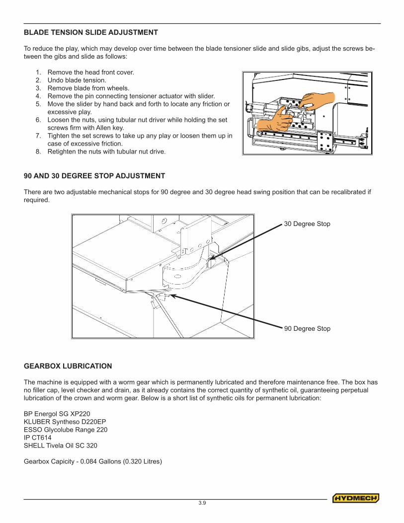
ANGLE BRAKE ADJUSTMENT
The clamping force on the swivel brake can be adjusted to ensure that the Head is held securely and does not move during cutting. The brake handle should be adjusted so that it does not “bottom out” or hit its movement limit, yet holds the head securely.
ANGLE BRAKE ADJUSTMENT PROCEDURE
STEP 1 Loosen locking cap screws “B” with a 6mm Allen key.
STEP 2 Tighten all 4 set screws “A” until snug with a 4mm Allen key
STEP 3 Back out the “A” screws ¼ of a turn
STEP 4 Tighten the locking cap screws “B”
STEP 5 Swing the head to 45° and back to ensure that the head moves freely and does not bind on the pivot surfaces. Continue to step 6 if necessary.
STEP 6 Adjust the clamping force bolt “C” with a 19mm wrench. If not tightened enough, the locking handle will “bottom out” and not hold the head firmly
A
C
B
A, C
B
B
3.9
BLADE TENSION SLIDE ADJUSTMENT
To reduce the play, which may develop over time between the blade tensioner slide and slide gibs, adjust the screws be-tween the gibs and slide as follows:
1. Remove the head front cover.2. Undo blade tension.3. Remove blade from wheels.4. Remove the pin connecting tensioner actuator with slider.5. Move the slider by hand back and forth to locate any friction or
excessive play.6. Loosen the nuts, using tubular nut driver while holding the set
screws firm with Allen key.7. Tighten the set screws to take up any play or loosen them up in
case of excessive friction.8. Retighten the nuts with tubular nut drive.
90 AND 30 DEGREE STOP ADJUSTMENT
There are two adjustable mechanical stops for 90 degree and 30 degree head swing position that can be recalibrated if required.
90 Degree Stop
30 Degree Stop
GEARBOX LUBRICATION
The machine is equipped with a worm gear which is permanently lubricated and therefore maintenance free. The box has no filler cap, level checker and drain, as it already contains the correct quantity of synthetic oil, guaranteeing perpetual lubrication of the crown and worm gear. Below is a short list of synthetic oils for permanent lubrication:
BP Energol SG XP220KLUBER Syntheso D220EPESSO Glycolube Range 220IP CT614SHELL Tivela Oil SC 320
Gearbox Capicity - 0.084 Gallons (0.320 Litres)
3.10
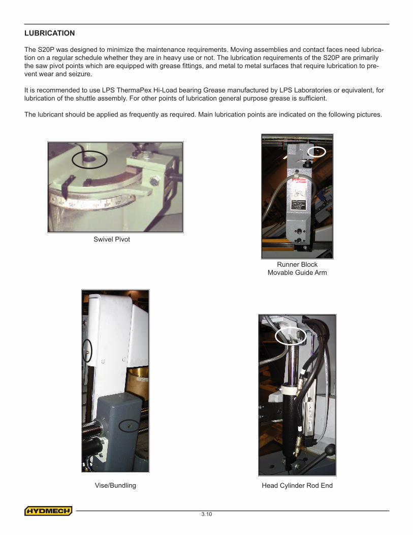
LUBRICATION
The S20P was designed to minimize the maintenance requirements. Moving assemblies and contact faces need lubrica-tion on a regular schedule whether they are in heavy use or not. The lubrication requirements of the S20P are primarily the saw pivot points which are equipped with grease fittings, and metal to metal surfaces that require lubrication to pre-vent wear and seizure.
It is recommended to use LPS ThermaPex Hi-Load bearing Grease manufactured by LPS Laboratories or equivalent, for lubrication of the shuttle assembly. For other points of lubrication general purpose grease is sufficient.
The lubricant should be applied as frequently as required. Main lubrication points are indicated on the following pictures.
Runner BlockMovable Guide Arm
Swivel Pivot
Head Cylinder Rod EndVise/Bundling

4.1
ELECTRICAL SCHEMATICS: SEE PDF ON ATTACHED CD
SECTION 4 - ELECTRICAL
5.1
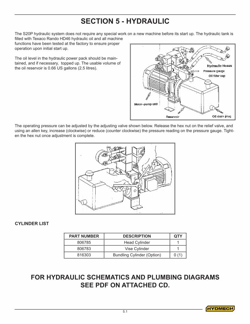
SECTION 5 - HYDRAULICThe S20P hydraulic system does not require any special work on a new machine before its start up. The hydraulic tank is filled with Texaco Rando HD46 hydraulic oil and all machine functions have been tested at the factory to ensure proper operation upon initial start up.
The oil level in the hydraulic power pack should be main-tained, and if necessary, topped up. The usable volume of the oil reservoir is 0.66 US gallons (2.5 litres).
PART NUMBER DESCRIPTION QTY806785 Head Cylinder 1806783 Vise Cylinder 1816303 Bundling Cylinder (Option) 0 (1)
CYLINDER LIST
The operating pressure can be adjusted by the adjusting valve shown below. Release the hex nut on the relief valve, and using an allen key, increase (clockwise) or reduce (counter clockwise) the pressure reading on the pressure gauge. Tight-en the hex nut once adjustment is complete.
FOR HYDRAULIC SCHEMATICS AND PLUMBING DIAGRAMS SEE PDF ON ATTACHED CD.

6.1
MECHANICAL ASSEMBLY DRAWINGS & PARTS LIST: SEE PDF ON ATTACHED CD
SECTION 6 - MECHANICAL ASSEMBLIES
7.1
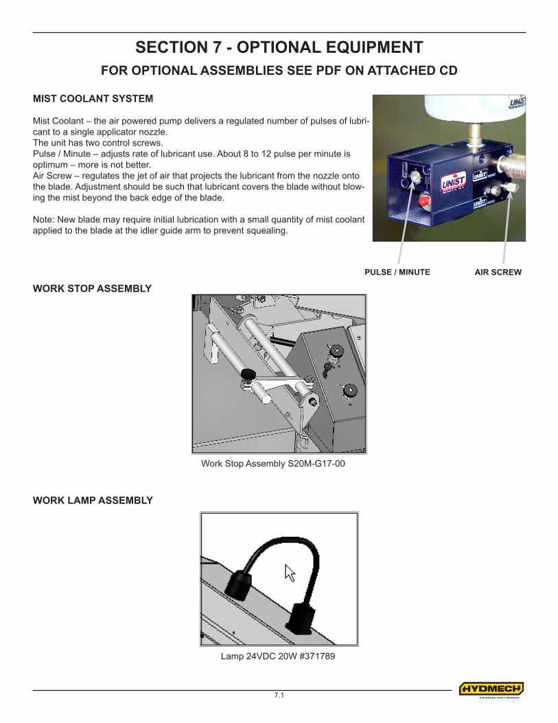
PULSE / MINUTE AIR SCREW
MIST COOLANT SYSTEM
Mist Coolant – the air powered pump delivers a regulated number of pulses of lubri-cant to a single applicator nozzle.The unit has two control screws.Pulse / Minute – adjusts rate of lubricant use. About 8 to 12 pulse per minute is optimum – more is not better.Air Screw – regulates the jet of air that projects the lubricant from the nozzle onto the blade. Adjustment should be such that lubricant covers the blade without blow-ing the mist beyond the back edge of the blade.
Note: New blade may require initial lubrication with a small quantity of mist coolant applied to the blade at the idler guide arm to prevent squealing.
SECTION 7 - OPTIONAL EQUIPMENT
WORK STOP ASSEMBLY
Work Stop Assembly S20M-G17-00
WORK LAMP ASSEMBLY
Lamp 24VDC 20W #371789
FOR OPTIONAL ASSEMBLIES SEE PDF ON ATTACHED CD
7.2
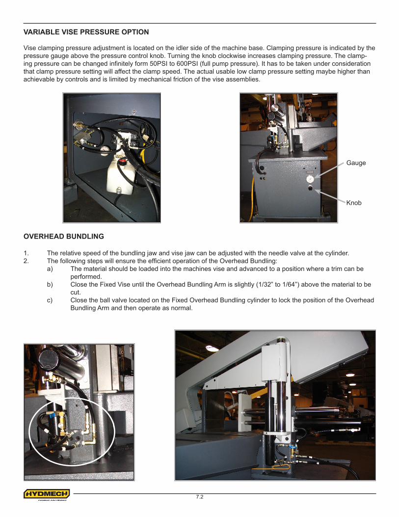
VARIABLE VISE PRESSURE OPTION
Vise clamping pressure adjustment is located on the idler side of the machine base. Clamping pressure is indicated by the pressure gauge above the pressure control knob. Turning the knob clockwise increases clamping pressure. The clamp-ing pressure can be changed infinitely form 50PSI to 600PSI (full pump pressure). It has to be taken under consideration that clamp pressure setting will affect the clamp speed. The actual usable low clamp pressure setting maybe higher than achievable by controls and is limited by mechanical friction of the vise assemblies.
OVERHEAD BUNDLING
1. The relative speed of the bundling jaw and vise jaw can be adjusted with the needle valve at the cylinder.2. The following steps will ensure the efficient operation of the Overhead Bundling: a) The material should be loaded into the machines vise and advanced to a position where a trim can be performed. b) Close the Fixed Vise until the Overhead Bundling Arm is slightly (1/32” to 1/64”) above the material to be cut. c) Close the ball valve located on the Fixed Overhead Bundling cylinder to lock the position of the Overhead Bundling Arm and then operate as normal.
Gauge
Knob
8.1
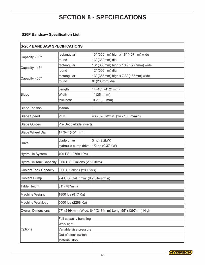
SECTION 8 - SPECIFICATIONS
S20P Bandsaw Specification List
S-20P BANDSAW SPECIFICATIONS
Capacity - 90ºrectangular 13” (355mm) high x 18” (457mm) wideround 13” (330mm) dia
Capacity - 45ºrectangular 13” (355mm) high x 10.9” (277mm) wideround 12” (305mm) dia
Capacity - 60ºrectangular 13” (355mm) high x 7.3” (185mm) wideround 8” (203mm) dia
Blade Length 14’-10” (4521mm) Width 1” (25.4mm) thickness .035” (.89mm)
Blade Tension Manual
Blade Speed VFD 46 - 328 sf/min (14 - 100 m/min)
Blade Guides Pre Set carbide inserts
Blade Wheel Dia. 17 3/4” (451mm)
Driveblade drive 3 hp (2.2kW)hydraulic pump drive 1/2 hp (0.37 kW)
Hydraulic System 400 PSI (2758 kPa)
Hydraulic Tank Capacity 0.66 U.S. Gallons (2.5 Liters)
Coolant Tank Capacity 6 U.S. Gallons (23 Liters)
Coolant Pump 2.4 U.S. Gal. / min (9.2 Liters/min)
Table Height 31” (787mm)
Machine Weight 1800 lbs (817 Kg)
Machine Workload 5000 lbs (2268 Kg)
Overall Dimensions 97” (2464mm) Wide, 84” (2134mm) Long, 55” (1397mm) High
Options
Full capacity bundlingWork lightVariable vise pressureOut of stock switchMaterial stop
8.2
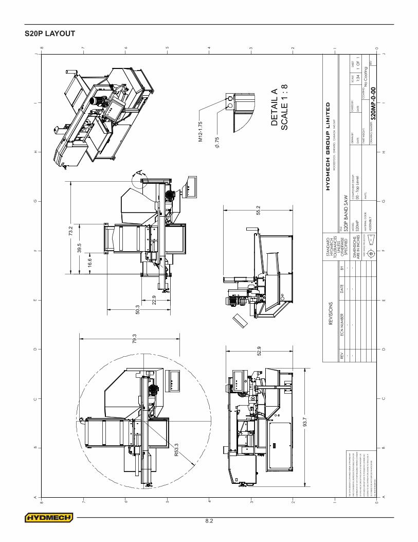
S20P LAYOUT
R53
.3
93.
7
CO
MPO
NEN
T G
ROUP
:
WO
OD
STO
CK.
ON
TARI
O.
CA
NA
DA
N4S
0A
9
HYD
MEC
H G
RO
UP L
IMIT
ED
--
--
-
ALL
RIG
HTS
RESE
RVED
.
ECN
NUM
BER
REV
DA
TEBY
REV
ISIO
NS
TO O
THER
S FO
R A
NY
PURP
OSE
WHA
TSO
EVER
.
LICEN
SE T
O U
SE O
R RI
GHT
OR
LICEN
SE T
O D
ISC
LOSE
IT
HYD
MEC
H G
ROUP
AN
D IT
S PO
SSES
ION
CO
NFE
RS N
O
OF
HYD
-MEC
H G
ROUP
.THIS
DA
TA IS
THE
PRO
PERT
Y O
F
DIS
TRIB
UTIO
N O
F A
NY
PART
REQ
UIRE
S W
RITT
EN C
ON
SEN
T
SPEC
IFIED
OTH
ERW
ISE
ARE
IN IN
CHE
STH
IRD
AN
GLE
PRO
JEC
TION
TITLE
DRW
N B
Y:
A
CHK
ED B
Y:
MA
T'L:
DA
TE:
SCA
LESH
EET
REV
DRA
WIN
G N
UMBE
R:S2
0MP-
0-00
1:34
1
BC
DE
FG
HI
J
AJ
IH
GF
ED
CB
012345678
08 7 6 5 4 3 2 1
DA
TE:
PART
WEI
GHT
:M
ATE
RIA
L C
OD
E:
ASS
EMBL
Y
00 -
Top
Leve
lS2
0MP
No
Coa
ting
CO
ATIN
G:
S20P
BA
ND
SA
W
OF
1
--
-TH
E D
ATA
/DES
IGN
CO
NTA
INED
HER
EIN
IS P
ROPR
IETA
RY
AN
D C
ON
FID
ENTIA
L.RE
PRO
DUC
TION
,PUB
LICA
TION
OR
STA
ND
ARD
HYD
MEC
H TO
LERA
NC
ES
UNLE
SS
DIM
ENSI
ON
S M
OD
EL:
79.3
52.
9
A
39.
5
22.
9
50.
3
16.
6
73.
2
55.2
DE
TAIL
AS
CA
LE 1
: 8
M12
-1.7
5
.75

9.1
Hyd-Mech Group Limited warrants parts/components on each new S20P bandsaw to be free from failure resulting from defective material and workmanship under proper use and service for a period of two years on following the date of shipment from the factory. Hyd·Mech’s sole obligation under this warranty is limited to the repair or replacement without charge, at Hyd·Mech’s factory, warehouse, or approved repair shop any part or parts which Hyd·Mech’s inspection shall disclose to be defective. Return freight must be pre-paid by the user.
This warranty, in its entirety, does not cover maintenance items, including but not limited to lubricating grease and oils, filters, V-belts, saw blades, etc., nor any items therein which show signs of neglect, overloading, abuse, accident, inadequate maintenance, or unauthorized altering.
MOTOR, GEARBOX, PUMP, ELECTRIC COMPONENTS, VALVES, HOSES, FITTINGS, and any other items used in the manufacture of the S20P, but not originally manufactured by Hyd·Mech are subject to the original manufacturer’s warranty. Hyd·Mech will provide such assistance and information as is necessary and available to facilitate the user’s claim to such other manufacturer.
Liability or obligation on the part of Hyd·Mech for damages, whether general, special or for negligence and expressly including any incidental and consequential damages is hereby disclaimed. Hyd·Mech’s obligation to repair or replace shall be the limit of its liability under this warranty and the sole and exclusive right and remedy of the user.
THIS WARRANTY IS EXPRESSLY IN LIEU OF ALL OTHER WARRANTIES, EXPRESSED ORIMPLIED, WRITTEN OR ORAL, INCLUDING WITHOUT LIMITATION ANY IMPLIED WARRANTIES OF MERCHANTABILITY OR FITNESS FOR A PARTICULAR PURPOSE.
This warranty may not be changed, altered, or modified in any way except in writing by Hyd-MechGroup Limited
HYD·MECH GROUP LIMITED1079 Parkinson RoadP.O. BOX 1030Woodstock, OntarioN4S 8P6Phone: (519) 539-6341Fax: (519) 539-5126Toll Free: (877) 276-SAWS (7297)E-mail: [email protected]
SECTION 9 - WARRANTY
Warranty