Embed Size (px)
Citation preview
S3 DISC MANUAL
1 2
INTRODUCTIONWelcome to the Cervélo family, and congratulations on your decision to purchase an S3 Disc.
You clearly recognize the difference that details and innovative engineering make to your riding experience. Because your new complete bicycle or frame set integrates the latest component technologies, we ask that you familiarize yourself with some of the new assembly and disassembly requirements before your first ride. This document has been prepared to guide you through these requirements, and is intended only as a supplement to the assembly instructions provided by your component manufacturer. If you choose to sell your Cervélo in the future, please pass this manual along.
TABLE OF CONTENTSIntroduction ......................................................................................................1Frame Features ................................................................................................2Fork Preparation ...............................................................................................3Small Parts .......................................................................................................5Frame Preparation ............................................................................................6Brake Housing Installation................................................................................7Mechanical Cable Routing ...............................................................................9Electric Cable Routing ....................................................................................11Seatpost Assembly & Installation ...................................................................15Seatpost Cutting Instructions .........................................................................16Through-Axle Wheel Installation .....................................................................17
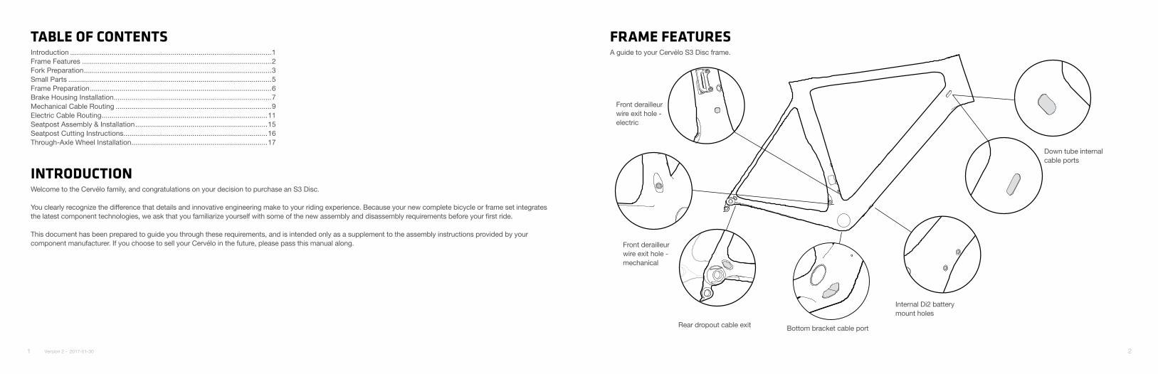
FRAME FEATURESA guide to your Cervélo S3 Disc frame.
Rear dropout cable exit
Front derailleur wire exit hole - mechanical
Bottom bracket cable port
Internal Di2 battery mount holes
Front derailleur wire exit hole - electric
Down tube internal cable ports
Version 2 - 2017-01-30
3 4
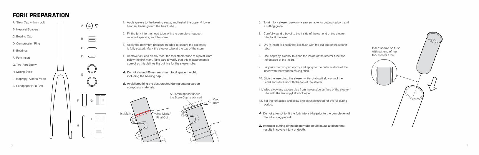
FORK PREPARATIONA
B
Max.4mm
A 2.5mm spacer under the Stem Cap is advised
1st Mark 2nd Mark / Final Cut
C
D
E
F G
H
I
J
A. Stem Cap + 5mm bolt
B. Headset Spacers
C. Bearing Cap
D. Compression Ring
E. Bearings
F. Fork Insert
G. Two-Part Epoxy
H. Mixing Stick
I. Isopropyl Alcohol Wipe
J. Sandpaper (120 Grit)
1. Apply grease to the bearing seats, and Install the upper & lower headset bearings into the head tube.
2. Fit the fork into the head tube with the complete headset, required spacers, and the stem.
3. Apply the minimum pressure needed to ensure the assembly is fully seated. Mark the steerer tube at the top of the stem.
4. Remove fork and clearly mark the fork steerer tube at a point 4mm below the first mark. Take care to verify that this measurement is correct as this defines the cut line for the steerer tube.
5. To trim fork steerer, use only a saw suitable for cutting carbon, and a cutting guide.
6. Carefully sand a bevel to the inside of the cut end of the steerer tube to fit the insert.
7. Dry fit insert to check that it is flush with the cut end of the steerer tube.
8. Use isopropyl alcohol to clean the inside of the steerer tube and the outside of the insert.
9. Fully mix the two-part epoxy and apply to the outer surface of the insert with the wooden mixing stick.
10. Slide the insert into the steerer while rotating it slowly until the flared end sits flush with the top of the steerer.
11. Wipe away any excess glue from the outside surface of the steerer tube with the isopropyl alcohol wipe.
12. Set the fork aside and allow it to sit undisturbed for the full curing period.
Do not attempt to fit the fork into a bike prior to the completion of the full curing period.
Avoid breathing the dust created during cutting carbon composite materials.
Improper cutting of the steerer tube could cause a failure that results in severe injury or death.
Do not exceed 50 mm maximum total spacer height, including the bearing cap.
Insert should be flushwith cut end of thefork steerer tube
5 6
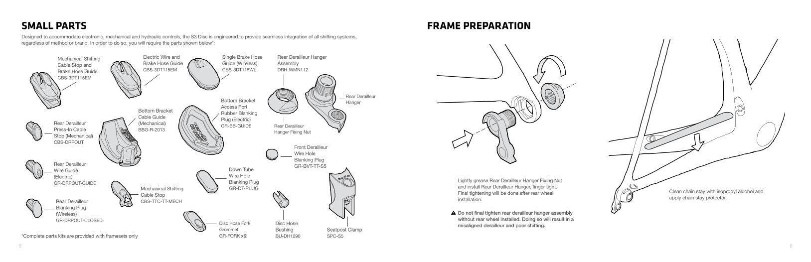
Bottom Bracket Cable Guide(Mechanical)BBG-R-2013
Disc Hose BushingBU-DH1290
Disc Hose Fork Grommet GR-FORK x2
Front Derailleur Wire HoleBlanking Plug GR-BVT-TT-S5
Down Tube Wire HoleBlanking PlugGR-DT-PLUG
Rear Derailleur Hanger
Rear Derailleur Hanger Fixing Nut
Rear Derailleur Hanger AssemblyDRH-WMN112
Rear Derailleur Press-In Cable Stop (Mechanical)CBS-DRPOUT
Rear Derailleur Blanking Plug (Wireless)GR-DRPOUT-CLOSED
Rear DerailleurWire Guide(Electric)GR-DRPOUT-GUIDE
Bottom Bracket Access Port Rubber Blanking Plug (Electric)GR-BB-GUIDE
Single Brake HoseGuide (Wireless)CBS-3DT115WL
Mechanical Shifting Cable Stop CBS-TTC-TT-MECH
Electric Wire and Brake Hose GuideCBS-3DT115EM
Mechanical Shifting Cable Stop and Brake Hose GuideCBS-3DT115EM
SMALL PARTSDesigned to accommodate electronic, mechanical and hydraulic controls, the S3 Disc is engineered to provide seamless integration of all shifting systems, regardless of method or brand. In order to do so, you will require the parts shown below*:
FRAME PREPARATION
Lightly grease Rear Derailleur Hanger Fixing Nut and install Rear Derailleur Hanger, finger tight. Final tightening will be done after rear wheel installation.
Do not final tighten rear derailleur hanger assembly without rear wheel installed. Doing so will result in a misaligned derailleur and poor shifting.
Seatpost ClampSPC-S5
Clean chain stay with isopropyl alcohol and apply chain stay protector.
*Complete parts kits are provided with framesets only
7 8
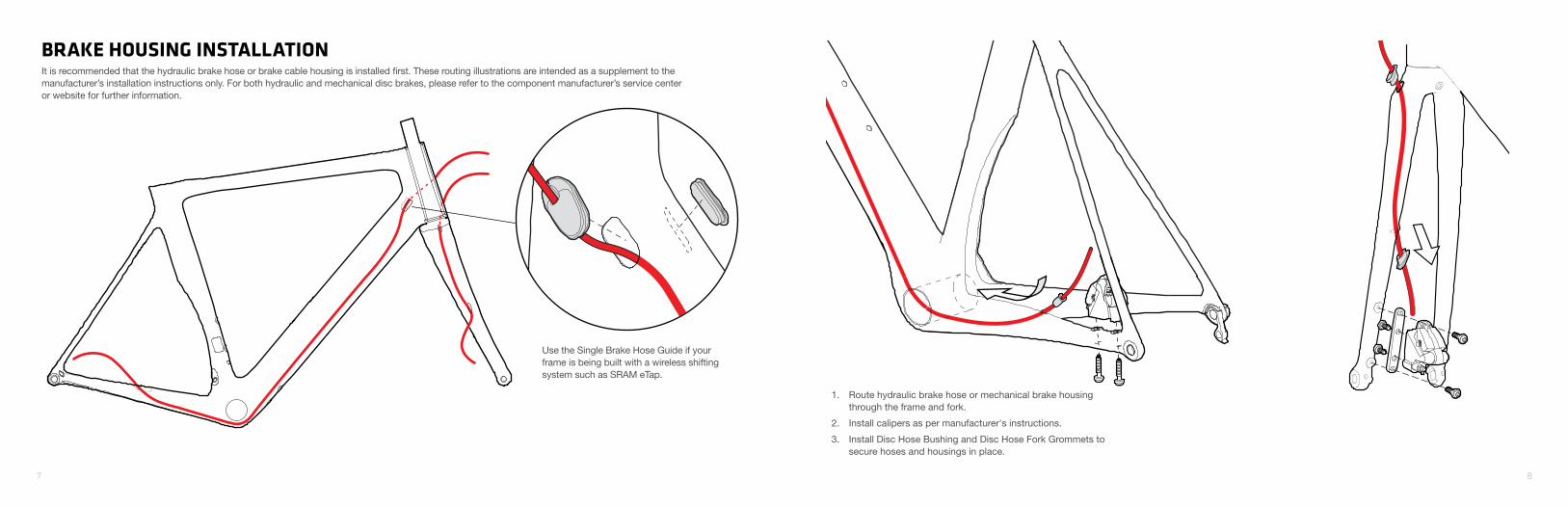
BRAKE HOUSING INSTALLATIONIt is recommended that the hydraulic brake hose or brake cable housing is installed first. These routing illustrations are intended as a supplement to the manufacturer’s installation instructions only. For both hydraulic and mechanical disc brakes, please refer to the component manufacturer’s service center or website for further information.
Use the Single Brake Hose Guide if your frame is being built with a wireless shifting system such as SRAM eTap.
1. Route hydraulic brake hose or mechanical brake housing through the frame and fork.
2. Install calipers as per manufacturer's instructions.
3. Install Disc Hose Bushing and Disc Hose Fork Grommets to secure hoses and housings in place.
9 10
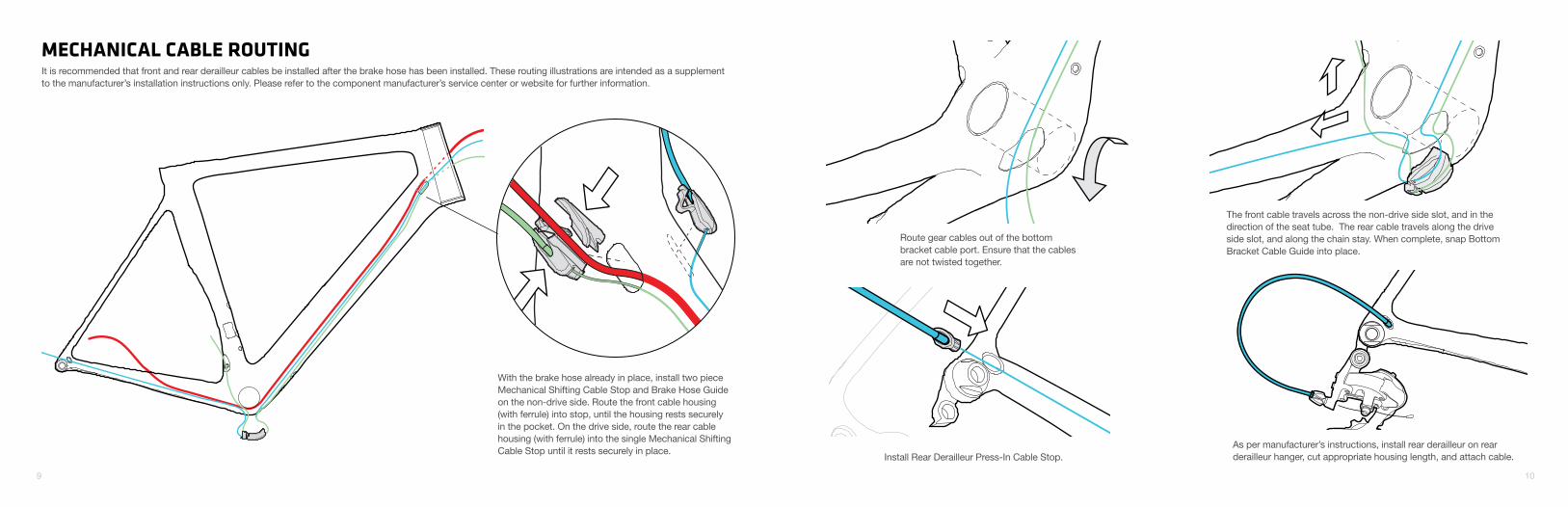
Route gear cables out of the bottom bracket cable port. Ensure that the cables are not twisted together.
The front cable travels across the non-drive side slot, and in the direction of the seat tube. The rear cable travels along the drive side slot, and along the chain stay. When complete, snap Bottom Bracket Cable Guide into place.
Install Rear Derailleur Press-In Cable Stop.As per manufacturer’s instructions, install rear derailleur on rear derailleur hanger, cut appropriate housing length, and attach cable.
With the brake hose already in place, install two piece Mechanical Shifting Cable Stop and Brake Hose Guide on the non-drive side. Route the front cable housing (with ferrule) into stop, until the housing rests securely in the pocket. On the drive side, route the rear cable housing (with ferrule) into the single Mechanical Shifting Cable Stop until it rests securely in place.
MECHANICAL CABLE ROUTINGIt is recommended that front and rear derailleur cables be installed after the brake hose has been installed. These routing illustrations are intended as a supplement to the manufacturer’s installation instructions only. Please refer to the component manufacturer’s service center or website for further information.
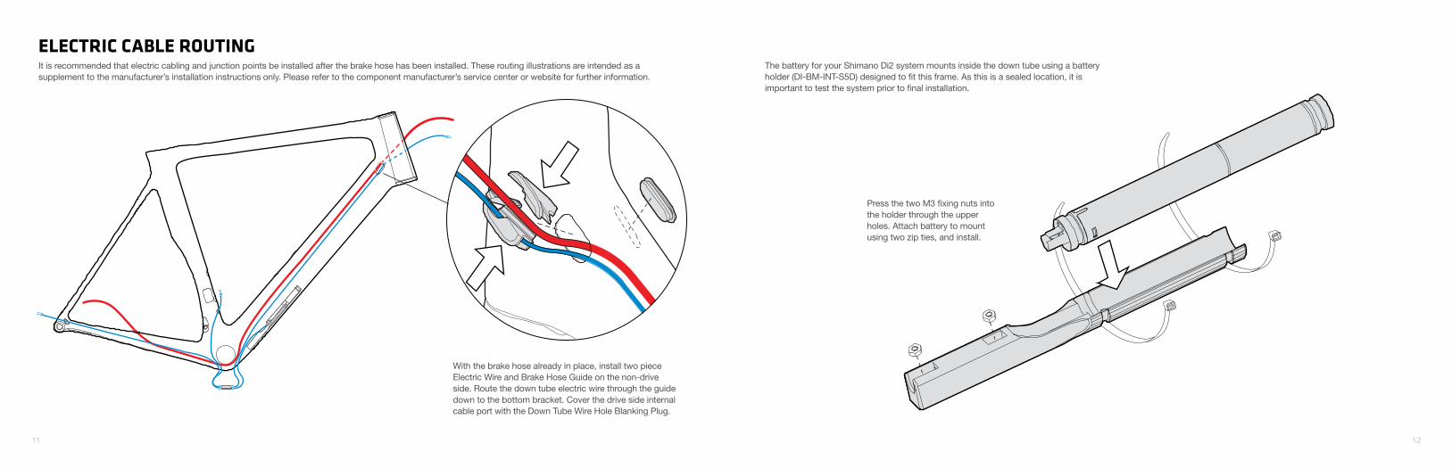
With the brake hose already in place, install two piece Electric Wire and Brake Hose Guide on the non-drive side. Route the down tube electric wire through the guide down to the bottom bracket. Cover the drive side internal cable port with the Down Tube Wire Hole Blanking Plug.
11 12
ELECTRIC CABLE ROUTINGIt is recommended that electric cabling and junction points be installed after the brake hose has been installed. These routing illustrations are intended as a supplement to the manufacturer’s installation instructions only. Please refer to the component manufacturer’s service center or website for further information.
The battery for your Shimano Di2 system mounts inside the down tube using a battery holder (DI-BM-INT-S5D) designed to fit this frame. As this is a sealed location, it is important to test the system prior to final installation.
Press the two M3 fixing nuts into the holder through the upper holes. Attach battery to mount using two zip ties, and install.
13 14
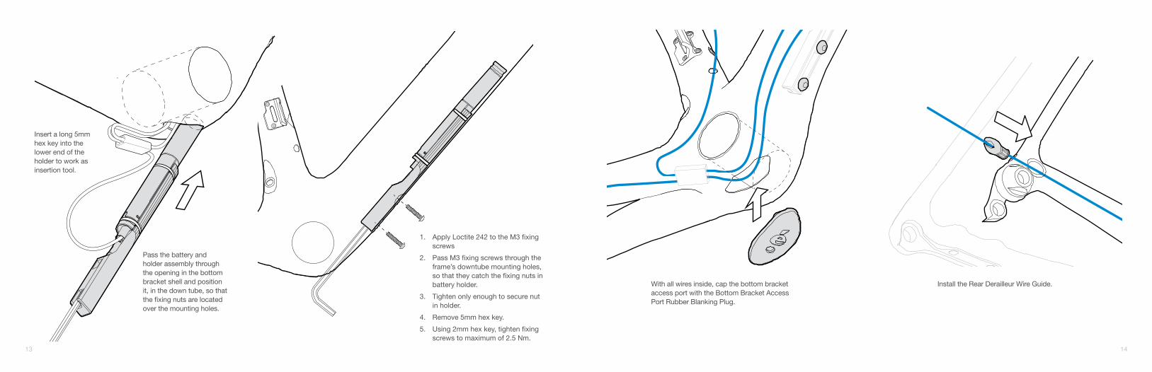
Insert a long 5mm hex key into the lower end of the holder to work as insertion tool.
Pass the battery and holder assembly through the opening in the bottom bracket shell and position it, in the down tube, so that the fixing nuts are located over the mounting holes.
With all wires inside, cap the bottom bracket access port with the Bottom Bracket Access Port Rubber Blanking Plug.
Install the Rear Derailleur Wire Guide.
1. Apply Loctite 242 to the M3 fixing screws
2. Pass M3 fixing screws through the frame’s downtube mounting holes, so that they catch the fixing nuts in battery holder.
3. Tighten only enough to secure nut in holder.
4. Remove 5mm hex key.
5. Using 2mm hex key, tighten fixing screws to maximum of 2.5 Nm.
15 16
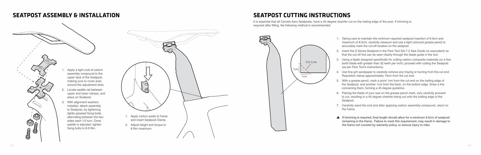
SEATPOST ASSEMBLY & INSTALLATION SEATPOST CUTTING INSTRUCTIONS
1. Apply a light coat of carbon assembly compound to the upper face of the Seatpost, making sure to cover area around the adjustment slots.
2. Locate saddle rail between upper and lower clamps, and place on Seatpost.
3. With alignment washers installed, attach assembly to Seatpost, by tightening lightly greased fixing bolts, alternating between the two sides each 1/2 turn. Once saddle is adjusted, tighten fixing bolts to 8-9 Nm.
It is essential that all Cervélo Aero Seatposts, have a 45 degree chamfer cut on the trailing edge of the post. If trimming is required after fitting, the following method is recommended:
1. Apply carbon paste to frame and insert Seatpost Clamp.
2. Adjust height and torque to 8 Nm maximum.
1. Taking care to maintain the minimum required seatpost insertion of 6.5cm and maximum of 8.5cm, carefully measure and use a light coloured grease pencil to accurately mark the cut-off location on the seatpost.
2. Insert the S Series Seatpost in the Park Tool SG-7.2 Saw Guide (or equivalent) so that the cut-off line can be seen clearly through the blade guide in the tool.
3. Using a blade designed specifically for cutting carbon composite materials (or a fine tooth blade with greater than 32 teeth per inch); proceed with cutting the Seatpost (as per Park Tool’s instructions).
4. Use fine grit sandpaper to carefully remove any fraying or burring from the cut end. Reposition clamp approximately 10cm from the cut end.
5. With a grease pencil, mark a point 1cm from the cut end on the trailing edge of the Seatpost, and another 1cm from the back, on the bottom edge. Draw a line connecting them, forming a 45 degree guideline.
6. Placing the blade of your saw on the grease pencil mark, very carefully proceed to cut, resulting in a 45 degree chamfer being cut onto the trailing edge of the Seatpost.
7. Carefully sand the end and after applying carbon assembly compound, return to the frame.
Cut Line
1cm
1cm
If trimming is required, final length should allow for a minimum 6.5cm of seatpost remaining in the frame. Failure to meet this requirement, may result in damage to the frame not covered by warranty policy, or serious injury to rider.
17 18
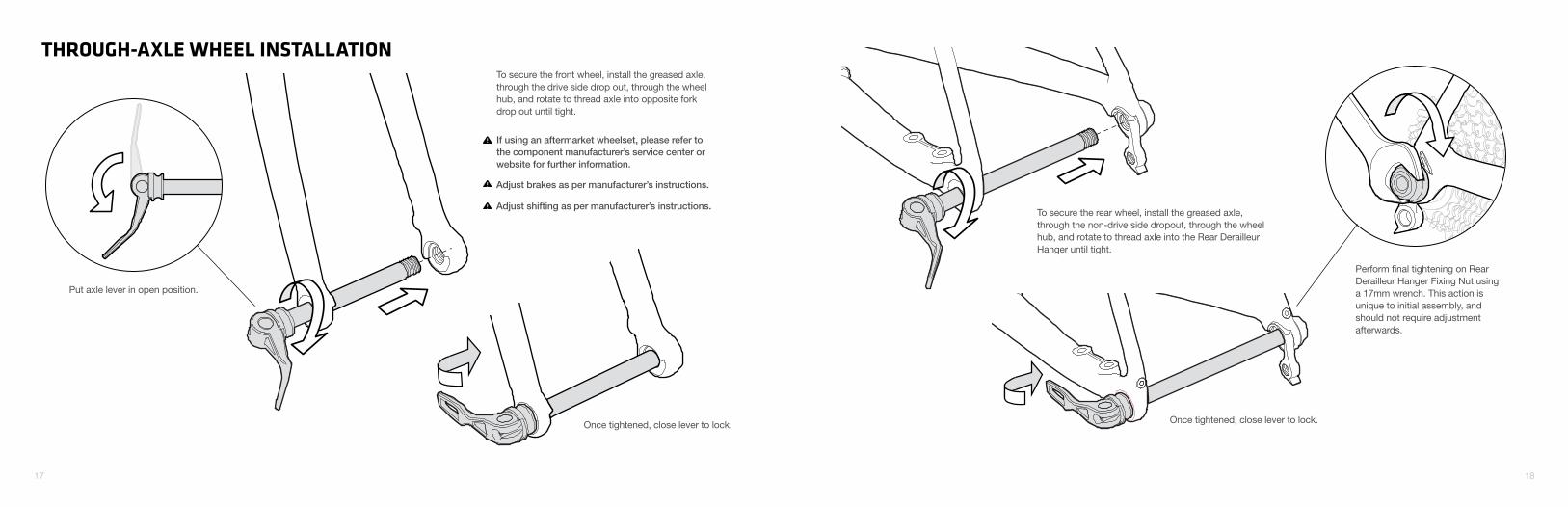
THROUGH-AXLE WHEEL INSTALLATION
Put axle lever in open position.
To secure the front wheel, install the greased axle, through the drive side drop out, through the wheel hub, and rotate to thread axle into opposite fork drop out until tight.
Once tightened, close lever to lock.
Adjust brakes as per manufacturer’s instructions.
Adjust shifting as per manufacturer’s instructions.
If using an aftermarket wheelset, please refer to the component manufacturer’s service center or website for further information.
To secure the rear wheel, install the greased axle, through the non-drive side dropout, through the wheel hub, and rotate to thread axle into the Rear Derailleur Hanger until tight.
Once tightened, close lever to lock.
Perform final tightening on Rear Derailleur Hanger Fixing Nut using a 17mm wrench. This action is unique to initial assembly, and should not require adjustment afterwards.
www.cervelo.com
S3 DISC MANUAL