Embed Size (px)
Citation preview

PN-P970640 (02/2000)
POWER BOX RAKE ®
MODEL S.6
OPERATOR’S MANUAL
DATE PURCHASED SERIAL NUMBER
1PN-P970640 (02/2000)
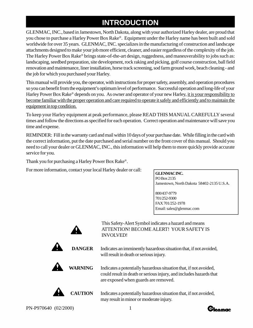
This Safety-Alert Symbol indicates a hazard and meansATTENTION! BECOME ALERT! YOUR SAFETY ISINVOLVED!
DANGER Indicates an imminently hazardous situation that, if not avoided,will result in death or serious injury.
WARNING Indicates a potentially hazardous situation that, if not avoided,could result in death or serious injury, and includes hazards thatare exposed when guards are removed.
CAUTION Indicates a potentially hazardous situation that, if not avoided,may result in minor or moderate injury.
GLENMAC INC.PO Box 2135Jamestown, North Dakota 58402-2135 U.S.A.
800/437-9779701/252-9300FAX 701/252-1978Email: [email protected]
GLENMAC, INC., based in Jamestown, North Dakota, along with your authorized Harley dealer, are proud thatyou chose to purchase a Harley Power Box Rake®. Equipment under the Harley name has been built and soldworldwide for over 35 years. GLENMAC, INC. specializes in the manufacturing of construction and landscapeattachments designed to make your job more efficient, cleaner, and easier regardless of the complexity of the job.The Harley Power Box Rake® brings state-of-the-art design, ruggedness, and maneuverability to jobs such as:landscaping, seedbed preparation, site development, rock raking and picking, golf course construction, ball fieldrenovation and maintenance, liner installation, horse track screening, sod farm ground work, beach cleaning - andthe job for which you purchased your Harley.
This manual will provide you, the operator, with instructions for proper safety, assembly, and operation proceduresso you can benefit from the equipment’s optimum level of performance. Successful operation and long-life of yourHarley Power Box Rake® depends on you. As owner and operator of your new Harley, it is your responsibility tobecome familiar with the proper operation and care required to operate it safely and efficiently and to maintain theequipment in top condition.
To keep your Harley equipment at peak performance, please READ THIS MANUAL CAREFULLY severaltimes and follow the directions as specified for each operation. Correct operation and maintenance will save youtime and expense.
REMINDER: Fill in the warranty card and mail within 10 days of your purchase date. While filling in the card withthe correct information, put the date purchased and serial number on the front cover of this manual. Should youneed to call your dealer or GLENMAC, INC., this information will help them to more quickly provide accurateservice for you.
Thank you for purchasing a Harley Power Box Rake®.
For more information, contact your local Harley dealer or call:
INTRODUCTION
2 PN-P970640 (02/2000)
Introduction ........................................................................... 1
Specifications ........................................................................ 2
Owner Assistance.................................................................. 3
General Information............................................................... 4
Bolt Size Chart ......................................................................4
Bolt Torque Chart ..............................................................5-6
Safety Rules .......................................................................6-9
Safety Decals ..................................................................10-11
Operation........................................................................12-17
Maintenance....................................................................18-23
Trouble Shooting................................................................. 20
Assembly ........................................................................24-30
Parts Identification and Drawings...................................28-31
Warranty.............................................................................. 32
Raking Width ............................................................................... 72 Inches
Roller Type .......................................... Tooth Roller Standard 8" Diameter
Roller Angle..................................................... 20 Degrees Both Directions
Gap (Tube to Barrier) .........................................1-1/8" - 2-1/2" Adjustable
Skid-steer Lift Capacity Requirement ............. SAE Lift Capacity 1,200 lbs
Skid-steer Hydraulic Requirement ....................... 11 GP @ 2200 psi (min.)
Tires ........................................................................................16.5 x 6.5 - 8
Tire Pressure ...................................................................................... 45 psi
Weight.............................................................................................. 890 lbs
Oil Capacity of Chain Case .................................. Approximately 1.5 Pints
TABLE OF CONTENTS
SPECIFICATIONS
3PN-P970640 (02/2000)
GLENMAC, INC. and your authorized Harley Dealer want you to be completely satisfied with your investment.Sometimes, however, misunderstandings can occur. To resolve any problem that may occur, please follow theinstructions below.
1. If you did not purchase your rake from an authorized Harley Dealer, go to number 2 below.
A. Contact the Service Manager of the dealership, explain the problem, and request assistance.If additional assistance is needed, your dealer has direct access to our home office.
B. If your problem has not been handled to your satisfaction, contact:
CUSTOMER SERVICE (8:00 am - 5:00 pm CT)GLENMAC, INC.PO BOX 2135JAMESTOWN ND 58402-2135701/252-9300800/437-9779
C. Please be prepared to provide the following information:
· Your name, address, and telephone number,· Machine model and SERIAL NUMBER,· Dealership name and address,· Machine purchase date,· Nature of problem.
Your problem will likely be resolved in the dealership using the dealer’s facilities, equipment, and personnel. Therefore,it is important that your initial contact be with the dealer.
2. If you did not purchase your equipment from an authorized dealer, call GLENMAC, INC., (see “B” above).There may be a new dealer in your area since you purchased your Harley Power Box Rake®. If there is nodealer in your area, our Customer Services Department can and will help you obtain the parts and informationyou may need. Please be prepared to provide the information requested under “C” above.
OWNER ASSISTANCE
4 PN-P970640 (02/2000)
The purpose of this manual is to assist you in operatingand maintaining your Power Box Rake®. Read itcarefully. It furnishes information and instructions thatwill help you achieve years of dependableperformance. These instructions have been compiledfrom extensive field experience and engineering data.Some information may be general in nature due tounknown and varying operating conditions. However,through experience and these instructions, you shouldbe able to develop procedures suitable to yourparticular situation.
The illustrations and data used in this manual werecurrent at the time of printing, but due to possible inlineproduction changes, your machine may vary slightlyin detail. We reserve the right to redesign and changethe machines as may be necessary withoutnotification.
Throughout this manual, references are made to front,back, right and left directions. These are determinedby sitting in the operator’s seat of the skid-steer.
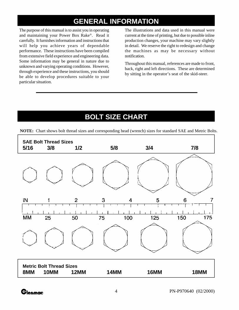
NOTE: Chart shows bolt thread sizes and corresponding head (wrench) sizes for standard SAE and Metric Bolts.
SAE Bolt Thread Sizes5/16 3/8 1/2 5/8 3/4 7/8
Metric Bolt Thread Sizes8MM 10MM 12MM 14MM 16MM 18MM
GENERAL INFORMATION
BOLT SIZE CHART
5PN-P970640 (02/2000)
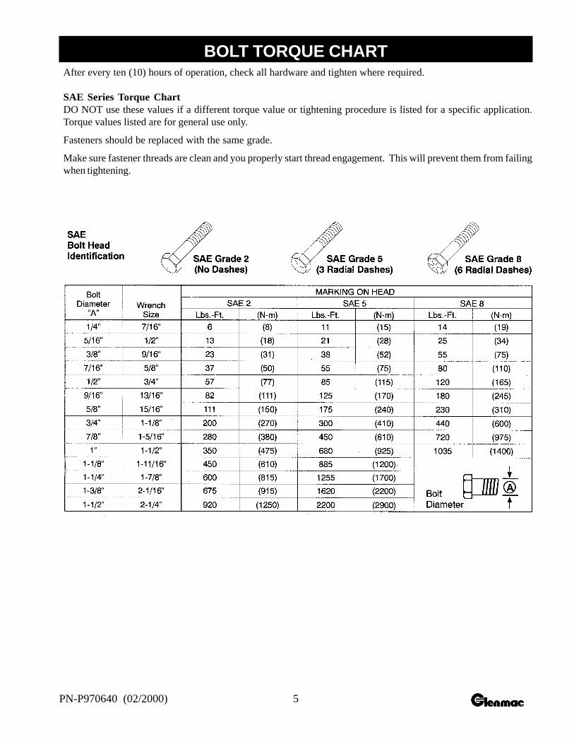
After every ten (10) hours of operation, check all hardware and tighten where required.
SAE Series Torque ChartDO NOT use these values if a different torque value or tightening procedure is listed for a specific application.Torque values listed are for general use only.
Fasteners should be replaced with the same grade.
Make sure fastener threads are clean and you properly start thread engagement. This will prevent them from failingwhen tightening.
BOLT TORQUE CHART
6 PN-P970640 (02/2000)
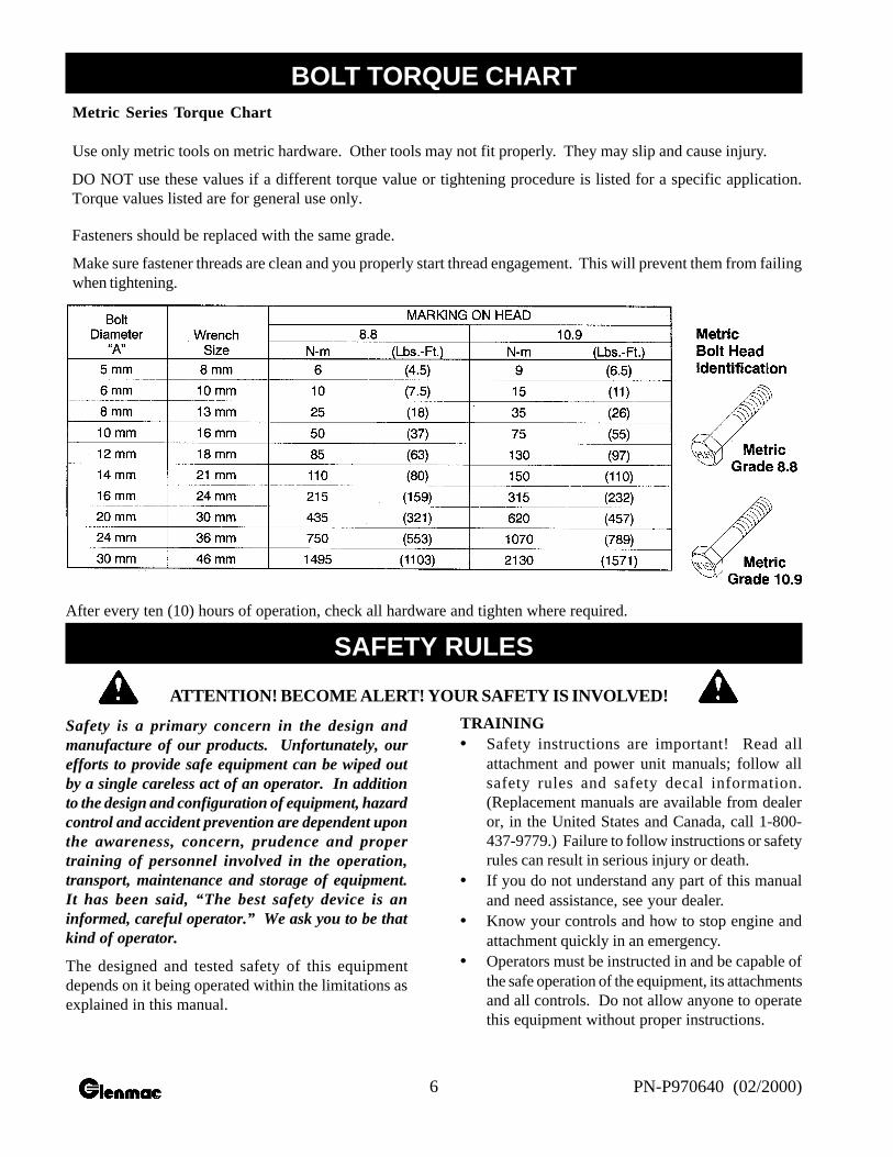
Metric Series Torque Chart
Use only metric tools on metric hardware. Other tools may not fit properly. They may slip and cause injury.
DO NOT use these values if a different torque value or tightening procedure is listed for a specific application.Torque values listed are for general use only.
Fasteners should be replaced with the same grade.
Make sure fastener threads are clean and you properly start thread engagement. This will prevent them from failingwhen tightening.
After every ten (10) hours of operation, check all hardware and tighten where required.
Safety is a primary concern in the design andmanufacture of our products. Unfortunately, ourefforts to provide safe equipment can be wiped outby a single careless act of an operator. In additionto the design and configuration of equipment, hazardcontrol and accident prevention are dependent uponthe awareness, concern, prudence and propertraining of personnel involved in the operation,transport, maintenance and storage of equipment.It has been said, “The best safety device is aninformed, careful operator.” We ask you to be thatkind of operator.
The designed and tested safety of this equipmentdepends on it being operated within the limitations asexplained in this manual.
TRAINING• Safety instructions are important! Read all
attachment and power unit manuals; follow allsafety rules and safety decal information.(Replacement manuals are available from dealeror, in the United States and Canada, call 1-800-437-9779.) Failure to follow instructions or safetyrules can result in serious injury or death.
• If you do not understand any part of this manualand need assistance, see your dealer.
• Know your controls and how to stop engine andattachment quickly in an emergency.
• Operators must be instructed in and be capable ofthe safe operation of the equipment, its attachmentsand all controls. Do not allow anyone to operatethis equipment without proper instructions.
BOLT TORQUE CHART
ATTENTION! BECOME ALERT! YOUR SAFETY IS INVOLVED!
SAFETY RULES

7PN-P970640 (02/2000)
• Keep hands and body away from pressurized lines.Use paper or cardboard, not body parts to checkfor leaks. Wear safety goggles. Hydraulic fluidunder pressure can easily penetrate skin and willcause serious injury or death.
• Make sure that all operating and service personnelknow that in the event hydraulic fluid penetratesskin, it must be surgically removed as soon aspossible by a doctor familiar with this form ofinjury, or gangrene, serious injury or death willresult. CONTACT A PHYSICIANIMMEDIATELY IF FLUID ENTERS SKINOR EYES. DO NOT DELAY.
• Do not allow children or untrained persons tooperate equipment.
PREPARATION
• Always check with your skid-steer manual ordealer for counter weight ballast that may berequired for machine stability.
• Air in hydraulic systems can cause erratic operationand allows loads or equipment components to dropunexpectedly. Before operating or allowinganyone to approach the equipment, purge any airin the system by operating all hydraulic functionsseveral times after connecting equipment,connecting hoses, or doing any hydraulicmaintenance.
• After connecting hoses, check that all control leverpositions function as instructed in the Operator’sManual. Do not operate until control lever andequipment movements are correct.
• Make sure all hydraulic hoses, fittings and valvesare in good condition and not leaking beforestarting power unit or using equipment. Checkand route hoses carefully to prevent damage.Hoses must not be twisted, bent sharply, kinked,frayed, pinched, or come into contact with anymoving parts. Operate moveable componentsthrough full operational range to check clearances.Replace any damaged hoses immediately.
• Always wear relatively tight and belted clothing toavoid entanglement in moving parts. Wear sturdy,rough-soled work shoes and protective equipmentfor eyes, hair, hands, hearing and head.
• Ensure implement is properly attached, adjusted
and in good operating condition. Skid-steer couplerlock-pins must be fully extended and properlyengaged into attachment retaining slots.
• Skid-steer must be equipped with ROPS and seatbelt/operator restraint. Keep seatbelt/operatorrestraint securely fastened/engaged. Falling offskid-steer can result in death from being run overor crushed. Keep ROPS systems in place at alltimes.
• Ensure all safety decals are installed. Replace ifdamaged. (See Safety Decals section for location.)
• Ensure shields and guards are properly installedand in good condition. Replace if damaged.
OPERATIONAL SAFETY
• Improper operation can cause the machine to tipor roll over and cause injury or death.• Keep skid-steer lift arms and attachment as
low as possible.• Do not travel or turn with skid-steer lift arms
and attachment raised.• Turn on level ground.• Go up and down slopes, not across them.• Keep the heavy end of the machine uphill.• Do not overload the machine.
• Never use the skid-steer attachment to carry loadsthat exceed skid-steer rated operating capacity orother skid-steer specifications. Check your skid-steer manual or with your dealer for skid-steer ratedoperating capacity. Exceeding this capacity cancause machine to tip or roll over and cause injuryor death.
• Use of a front safety door on the skid-steer isrecommended for operation of the Power BoxRake®.
• Do not allow other people in the area whenoperating, attaching, removing, and assembling orservicing equipment.
• Only engage power when equipment is at groundoperating level. Always disengage power whenequipment is raised off the ground.
• Do not disconnect hydraulic lines until all systempressure is relieved. Lower unit to ground, stopengine, and operate all hydraulic control levers.
• Keep bystanders away from equipment while it isin operation.
ATTENTION! BECOME ALERT! YOUR SAFETY IS INVOLVED!
SAFETY RULES
8 PN-P970640 (02/2000)
• Never go underneath equipment lowered to theground or raised. Never place any part of the bodyunderneath equipment or between moveable partseven when the engine has been turned off.Hydraulic system leak down, hydraulic systemfailures, mechanical failures or movement ofcontrol levers can cause equipment to drop or rotateunexpectedly and cause severe injury or death.
• Service work does not require going underneath.• Read Operator’s Manual for service instructions
or have done by a qualified dealer.• Never direct discharge toward people, animals or
property.• Do not operate equipment while under the influence
of alcohol or drugs.• Operate only in the daylight or good artificial light.• Keep hands, feet, hair and clothing away from
equipment while engine is running. Stay clear ofall moving parts.
• Always comply with all state and local lighting andmarking requirements.
• Do not allow riders. Do not lift or carry anybodyon the skid-steer or attachments.
• Always sit in skid-steer seat when operatingcontrols or starting engine. Securely fasten seatbelt/operator restraint, place transmission in parkor neutral, engage brake and ensure all othercontrols are disengage before starting skid-steerengine.
• Look down and to the rear and make sure area isclear before operating in reverse.
• Use extreme care when working close to fences,ditches, other obstructions, or on hillsides.
• Do not operate on steep slopes.• Do not stop, start or change directions suddenly on
slopes.• Use extreme care and reduce ground speed on
slopes and rough terrain.• Watch for hidden hazards on the terrain during
operation.• Stop skid-steer and implement immediately upon
striking an obstruction. Dismount skid-steer usingproper procedure. Inspect and repair any damagebefore resuming operation.
• Before leaving skid-steer operator’s seat, followskid-steer manual instructions. Lower skid-steerlift arms and put attachment on the ground. Stopengine, remove key, engage brake, and removeseat belt/operator restraint.
MAINTENANCE SAFETY
• Your dealer can supply original equipment hydraulicaccessories and repair parts. Substitute parts maynot meet original equipment specifications and maybe dangerous.
• Always wear relatively tight and belted clothing toavoid entanglement in moving parts. Wear sturdy,rough-soled work shoes and protective equipmentfor eyes, hair, hands, hearing and head.
• Do not allow other people in the area whenoperating, attaching, removing, and assembling orservicing equipment.
• Never go underneath equipment lowered to theground or raised. Never place any part of the bodyunderneath equipment or between moveable partseven when the engine has been turned off.Hydraulic system leak down, hydraulic systemfailures, mechanical failures or movement ofcontrol levers can cause equipment to drop or rotateunexpectedly and cause severe injury or death.Service work does not require going underneathequipment. Read Operator’s Manual for serviceinstructions or have done by a qualified dealer.
• Avoid electrical system hazards. Never work onthe electrical system unless you are qualified andthoroughly familiar with system details and thespecial handling requirements. Disconnect batterybefore working on electrical system. Remove“ground” cable first. When reconnecting battery,connect “ground” cable last.
• Ensure implement is properly attached, adjustedand in good operating condition. Skid-steercoupler lock-pins must be fully extended andproperly engaged into attachment retaining slots.
• Never perform service or maintenance with enginerunning.
• Keep all persons away from operator control areawhile performing adjustments, service ormaintenance.
ATTENTION! BECOME ALERT! YOUR SAFETY IS INVOLVED!
SAFETY RULES
9PN-P970640 (02/2000)
• Tighten all bolts, nuts and screws, and check thatall cotter pins are installed securely to ensureequipment is in a safe condition before operating.
• Ensure all safety decals are installed. Replace ifdamaged. (See Safety Decals section for location.)
• Ensure shields and guards are properly installedand in good condition. Replace if damaged.
• Before leaving skid-steer operator’s seat, followskid-steer manual instructions. Lower skid-steerlift arms and put attachment on the ground. Stopengine, remove key, engage brake, and removeseat belt/operator restraint.
• Do not disconnect hydraulic lines until all systempressure is relieved. Lower unit to ground, stopengine, and operate all hydraulic control levers.
STORAGE
• Follow manual instructions for storage.• Keep children and bystanders away from storage
area.
Review the video included withyour Rake for safety tips!
Notes
ATTENTION! BECOME ALERT! YOUR SAFETY IS INVOLVED!
SAFETY RULES
10 PN-P970640 (02/2000)
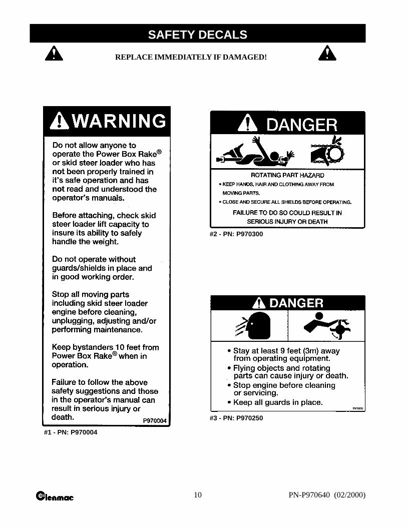
#1 - PN: P970004
#2 - PN: P970300
#3 - PN: P970250
REPLACE IMMEDIATELY IF DAMAGED!
SAFETY DECALS
11PN-P970640 (02/2000)
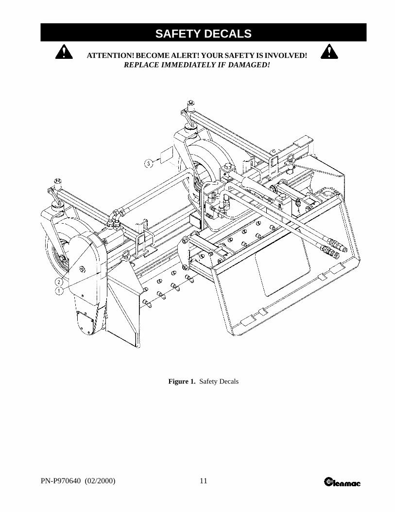
Figure 1. Safety Decals
ATTENTION! BECOME ALERT! YOUR SAFETY IS INVOLVED!REPLACE IMMEDIATELY IF DAMAGED!
SAFETY DECALS
12 PN-P970640 (02/2000)
Safety is a primary concern in the design andmanufacture of our products. Unfortunately, our effortsto provide safe equipment can be wiped out by a singlecareless act of an operator.
In addition to the design and configuration of equipment,hazard control and accident prevention are dependentupon the awareness, concern, prudence, and propertraining of personnel involved in the operation, transport,maintenance, and storage of equipment.
It has been said, “The best safety device is aninformed, careful operator.” We ask you to be thatkind of an operator.
The operator is responsible for the safe operation ofthis equipment. Operators must be instructed in andbe capable of the safe operation of the equipment, itsattachments, and all controls. Do not allow anyone tooperate this equipment without proper instructions.
The S·6 Power Box Rake® is designed for removingrock and small debris, and for thatching. Skid-steersmust be equipped with an auxiliary hydraulic systemcapable of supplying continuous flow for hydraulicmotor operation. This manual contains information forthe S·6 model. Refer to the information in this manualfor specifications, parts, assemblies, and adjustments.
WARNING
• Safety instructions are important! Read allattachment and power unit manuals; followall safety rules and safety decal information.(Replacement manuals are available fromdealer or, in the United States and Canada,call 1-800-437-9779.) Failure to followinstructions or safety rules can result inserious injury or death.
• Do not allow children or untrained personsto operate equipment.
• Skid-steer must be equipped with ROPSand seat belt/operator restraint. Keep seatbelt/operator restraint securely fastened/engaged. Falling off skid-steer can result indeath from being run over or crushed.Keep ROPS systems in place at all times.
• Do not allow other people in the area whenoperating, attaching, removing, assembling,or servicing equipment.
• Never go underneath equipment lowered tothe ground or raised. Never place any part ofthe body underneath equipment or betweenmoveable parts even when the engine hasbeen turned off. Hydraulic system leakdown, hydraulic system failures, mechanicalfailures, or movement of control levers cancause equipment to drop or rotateunexpectedly and cause severe injury ordeath.
• Service work does not require goingunderneath.
• Read Operator’s Manual for serviceinstructions or have done by a qualifieddealer.
• Before leaving skid-steer operator’s seat,follow skid-steer manual instructions. Lowerskid-steer lift arms and put attachment onthe ground. Stop engine, remove key, engagebrake, and remove seat belt/operatorrestraint.
ATTACHING POWER RAKE TO SKID-STEER
Read the skid-steer Operator’s Manual connecting andremoving instruction.
Position hydraulic hoses so they will not be pinchedwhen connecting the power rake.
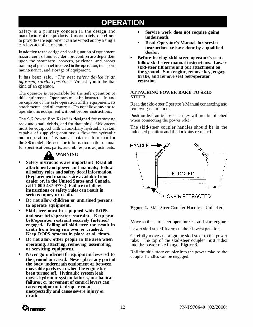
The skid-steer coupler handles should be in theunlocked position and the lockpins retracted.
Figure 2. Skid-Steer Coupler Handles - Unlocked
Move to the skid-steer operator seat and start engine.
Lower skid-steer lift arms to their lowest position.
Carefully move and align the skid-steer to the powerrake. The top of the skid-steer coupler must indexinto the power rake flange, Figure 3.
Roll the skid-steer coupler into the power rake so thecoupler handles can be engaged.
OPERATION
13PN-P970640 (02/2000)
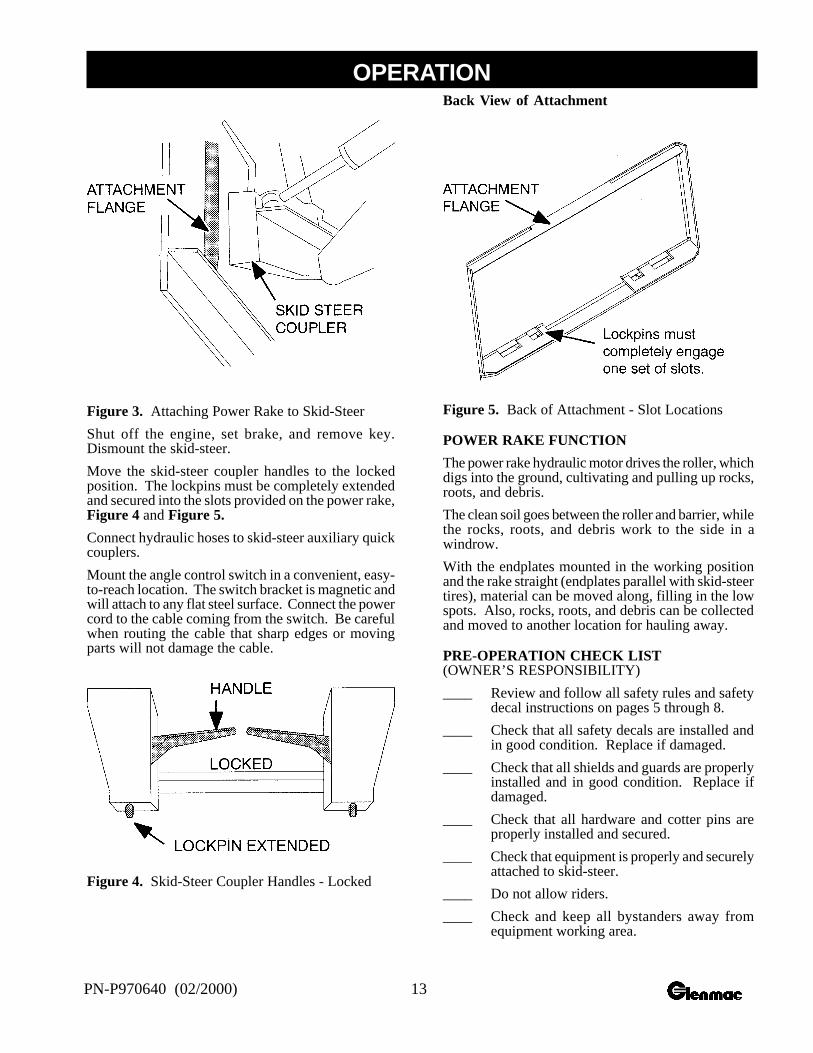
Figure 3. Attaching Power Rake to Skid-Steer
Shut off the engine, set brake, and remove key.Dismount the skid-steer.
Move the skid-steer coupler handles to the lockedposition. The lockpins must be completely extendedand secured into the slots provided on the power rake,Figure 4 and Figure 5.
Connect hydraulic hoses to skid-steer auxiliary quickcouplers.
Mount the angle control switch in a convenient, easy-to-reach location. The switch bracket is magnetic andwill attach to any flat steel surface. Connect the powercord to the cable coming from the switch. Be carefulwhen routing the cable that sharp edges or movingparts will not damage the cable.
Figure 4. Skid-Steer Coupler Handles - Locked
Back View of Attachment
Figure 5. Back of Attachment - Slot Locations
POWER RAKE FUNCTION
The power rake hydraulic motor drives the roller, whichdigs into the ground, cultivating and pulling up rocks,roots, and debris.
The clean soil goes between the roller and barrier, whilethe rocks, roots, and debris work to the side in awindrow.
With the endplates mounted in the working positionand the rake straight (endplates parallel with skid-steertires), material can be moved along, filling in the lowspots. Also, rocks, roots, and debris can be collectedand moved to another location for hauling away.
PRE-OPERATION CHECK LIST(OWNER’S RESPONSIBILITY)
____ Review and follow all safety rules and safetydecal instructions on pages 5 through 8.
____ Check that all safety decals are installed andin good condition. Replace if damaged.
____ Check that all shields and guards are properlyinstalled and in good condition. Replace ifdamaged.
____ Check that all hardware and cotter pins areproperly installed and secured.
____ Check that equipment is properly and securelyattached to skid-steer.
____ Do not allow riders.
____ Check and keep all bystanders away fromequipment working area.
OPERATION
14 PN-P970640 (02/2000)
____ Check all lubrication points and grease asinstructed in the Maintenance section startingon page 18.
____ Check that all hydraulic hoses and fittings arein good condition and not leaking beforestarting skid-steer. Check that hoses are nottwisted, bent sharply, kinked, frayed, or pulledtight. Replace any damaged hosesimmediately.
____ Make sure skid-steer ROPS and seat belt arein good condition. Keep seat belt securelyfastened during operation.
OPERATING INSTRUCTIONS
Read and understand the power rake and skid-steerOperator’s Manuals before operating the power rake.Failure to do so may result in death, serious personalinjury, or property damage.
Never raise the power rake more than a few inches offthe ground when traveling from job site to job site.
Shut off the engine, set brake, remove key, removeseat belt, and release operator restraint. Dismount theskid-steer.
WARNING
• Improper operation can cause the machineto tip or roll over and cause injury or death.• Keep skid-steer lift arms and attachment
as low as possible.• Do not travel or turn with skid-steer lift
arms and attachment raised.• Turn on level ground.• Go up and down slopes, not across them.• Keep the heavy end of the machine uphill.• Do not overload the machine.
• Look down and to the rear and make surearea is clear before operating in reverse.
• Never direct discharge toward people,animals, or property.
• Only engage power when equipment is atground operating level. Always disengagepower when equipment is raised off the ground.
Start-up Sequence
WARNING
• Only engage power when equipment is atground operating level. Always disengagepower when equipment is raised off the ground.
Start skid-steer engine.
Lower power rake slowly to the ground.
Engage hydraulic control lever for auxiliary implements.
Increase engine rpm to give desired rpm at the roller.Normal operating speed is approximately 270 rpm. Ifoperating in heavy rock, reduce the speed slightly.
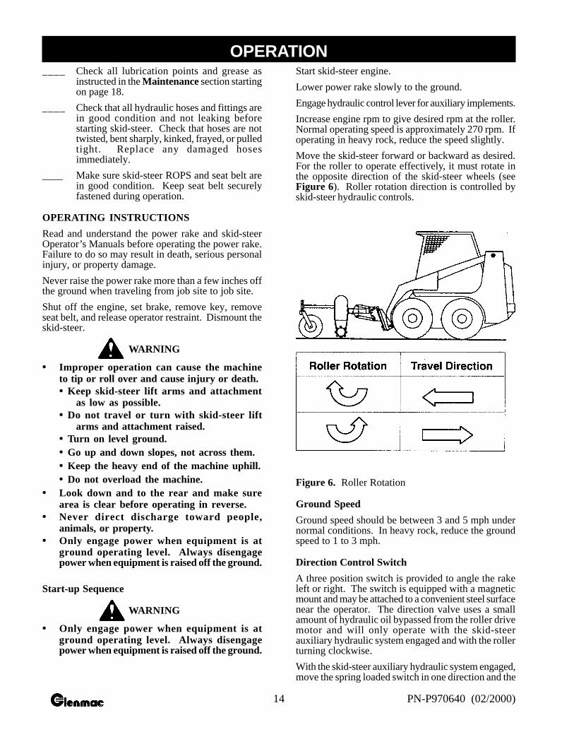
Move the skid-steer forward or backward as desired.For the roller to operate effectively, it must rotate inthe opposite direction of the skid-steer wheels (seeFigure 6). Roller rotation direction is controlled byskid-steer hydraulic controls.
Figure 6. Roller Rotation
Ground Speed
Ground speed should be between 3 and 5 mph undernormal conditions. In heavy rock, reduce the groundspeed to 1 to 3 mph.
Direction Control Switch
A three position switch is provided to angle the rakeleft or right. The switch is equipped with a magneticmount and may be attached to a convenient steel surfacenear the operator. The direction valve uses a smallamount of hydraulic oil bypassed from the roller drivemotor and will only operate with the skid-steerauxiliary hydraulic system engaged and with the rollerturning clockwise.
With the skid-steer auxiliary hydraulic system engaged,move the spring loaded switch in one direction and the
OPERATION
15PN-P970640 (02/2000)
rake will angle left or right. Return the switch to centerposition and rake will maintain the angle selected.
Pivot rake to place the windrow left or right of theskid-steer.
Hydraulic Drive Motor
The hydraulic drive motor runs off the auxiliary circuitof the skid-steer. The power rake should be run at30% power for one hour for proper motor break-in.
Power Roller
Roller should be level with the ground. The powerrake should also be level with the ground front to back.To accomplish this, raise or lower gauge wheels and/or use the skid-steer’s tilt cylinder.
To allow the roller to penetrate deeper into the ground,loosen the handle and raise the gauge wheels. Toachieve the opposite, lower the gauge wheels.
The chain case end of roller weighs about 90 lbs. morethan the other end of roller. To compensate for this,you should set the tire closest to the chain case down1" lower than opposite tire. This will still give an evengrade when landscaping and will prevent unusual orexcess wear on the teeth on that end of the roller.
During operation, further depth control can be achievedby tilting the rake forward on gauge wheels to raiseroller, or by tilting the rake back to raise gauge wheelsand allow more roller penetration.
Be sure to check the air pressure in each tire regularlyso that an even, consistent grade will be maintained.
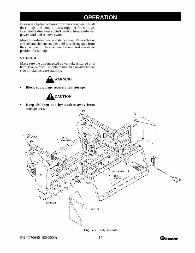
The normal gap between the roller and barrier foraverage conditions is about 1-1/4". This gap can beadjusted either wider or narrower by loosening the U-bolt that holds the barrier mount and sliding it up ordown. A wider opening will allow more dirt and rockto pass through. For finer raking, reduce the gap. (Becareful not to let roller hit barrier.) The gap should bethe same all the way across. Barrier adjustment isshown in Figure 7.
The roller on the power rake is bi-rotational . Youcan operate the roller in both directions - clockwiseand counter-clockwise. The roller operates mostefficiently when it rotates in the opposite direction ofthe skid-steer wheels.
Operating Depth
When power raking, the depth will determine how muchdirt is carried ahead of the roller. The ideal depth willvary with conditions and can be anywhere fromskimming the surface to about 3" deep. Seeinstructions in Power Roller above to set roller depth.
When making the first windrow, the level of dirt maybe halfway up on the barrier. When moving thewindrow two or three times, the level of the dirt maybe to the top of the barrier. However, try to preventmaterial from flowing over the top.
The power rake allows fast raking of large areas ofground by being able to move windrows several times.Of course, the volume or density of the material beingraked will dictate how many times a windrow can bemoved.
Endplates
The function of the endplates is to contain the materialin front of the roller while the clean material passesbetween the roller and barrier.
With the endplates mounted in the working positionand the rake straight (parallel with skid-steer tires),material can be moved along, filling in the low spots.
By decreasing the gap between the roller and barrier,more material can be pulled along. Barrier adjustmentis shown in Figure 7.
These plates can be mounted to the front or back ofthe power rake, depending on the raking direction.When you move the endplates from front to back, youmust move the left one to the right side and the rightone to the left side.
Make sure the disconnected power rake is stored on ahard, level surface. Use the endplates mounted onattachment side of rake to ensure stability.
Parallel Arms
The function of the parallel arms is to allow the powerrake to “float” and follow the contour of the ground.Lock-out pins are supplied to allow more aggressiveaction. However, the hydraulic motor may stall out iftoo much down pressure is applied. See Figure 7 forpin “float” and “lock-out” positions.
Operator Production
Successful operation of the power rake will come withoperator experience. The rake’s performance alsodepends on the type and size of the skid-steer it’smounted on.
An operator that masters the technique of adjustingthe angle of attack of the roller against the soil willalso find ideal settings under various conditions to givethe desired results.
OPERATION
16 PN-P970640 (02/2000)
IMPORTANT
• Do not drop power rake to the ground withthe roller turning. Sudden high speed joltsmultiply stress to the driveline and can causeextreme damage.
Application Techniques
The power rake is capable of many applications. Thefollowing are some of the common applications:
Pulverizing Topsoil
For breaking up compacted soil or conditioninghardened baseball diamonds, the parallel arm lockingpins are set in the “lock-out” position so that downpressure can be exerted on the tooth roller. Theattachment plate is rolled back to take the guide wheelsoff the ground so only the toothed roller is in contactwith the ground. Maintain sufficient rpm to avoidstalling the toothed roller in its progress. The rake canbe straight or angled, but the endplates should not bemounted in order to allow material to move out of theway and not slow the process.
Debris Removal
Once the surface has been loosened, the process ofremoving debris can begin. The parallel arm lockingpins are removed and stored in the “float” positionholes. This allows the rake to begin the early stagesof the final grading process. The skid-steer attachmentplate is tilted forward until the guide wheels controlthe depth of the toothed roller. The rake can be angledat this time for windrowing debris or the rake can beset straight with both endplates installed to collectdebris. Skid-steer travel speed should be increasedfor this process.
Finish Grading
For this operation, set the rake’s parallel arms in the“float” position and mount both endplates in theforward position. The rake is tilted forward until theteeth of the toothed roller are barely touching the soil.Skid-steer speed can be increased for this operation,the idea being to collect material from the high spotsand leave it in the low areas.
Spreading Fill and Topsoil
Start with parallel arms in “lock-out” position and raketilted on gauge wheels, since depth of cut is not theobjective. Endplates can be installed and the windrowangle set as needed to control the material movement.
Changing Grade
Grade modification can be accomplished during finishgrading by angling the rake to collect and windrowthe maximum amount of material toward targetedareas.
Thatching Existing Grass Areas
This procedure is done with parallel arms in the “lock-out” position so maximum depth control can bemaintained. The skid-steer attachment plate shouldbe tilted forward to support the rake on the front gaugewheels and toothed roller raised so teeth are just grazingthe surface. Travel speed should be slow and careful.
Shutting Down
Stop engine.
Lower the lift arms and power rake to the ground.
Purge any air in the system. Hydraulic system leakdown, hydraulic system failures, mechanical failures,or movement of control levers can cause equipment todrop or rotate unexpectedly.
Shut off engine, set brake, remove key, remove seatbelt, and release operator restraint before leaving theskid-steer operator’s seat.
WARNING
• Do not disconnect hydraulic lines until allsystem pressure is relieved. Lower unit toground, stop engine, and operate all hydrauliccontrol levers.
REMOVING POWER RAKE FROM SKID-STEER
WARNING
• Do not allow other people in the area whenoperating, attaching, removing, assembling,or servicing equipment.
Install endplates on attachment side of power rake asshown in Figure 7.
On a hard level surface, lower attachment to the ground.
Shut off engine, set brake, remove key, remove seatbelt, and release operator restraint before leaving theskid-steer operator’s seat.
WARNING
• Do not disconnect hydraulic lines until allsystem pressure is relieved. Lower unit toground, stop engine, and operate all hydrauliccontrol levers.
Move attachment coupler latches to the unlockedposition (lockpins must be disengaged).
OPERATION
17PN-P970640 (02/2000)
Disconnect hydraulic hoses from quick couplers. Installdust plugs and couple hoses together for storage.Disconnect direction control switch from skid-steerpower cord and remove switch.
Move to skid-steer seat and start engine. Release brakeand roll attachment coupler until it is disengaged fromthe attachment. The attachment should rest in a stableposition for storage.
STORAGE
Make sure the disconnected power rake is stored on ahard, level surface. Endplates mounted on attachmentside of rake increase stability.
WARNING
• Block equipment securely for storage.
CAUTION
• Keep children and bystanders away fromstorage area.
Figure 7. Adjustments
OPERATION
18 PN-P970640 (02/2000)
The information in this section is written for operatorswho possess basic mechanical skills. Should you needhelp, your dealer has trained service techniciansavailable. For your protection, read and follow allsafety information in this manual.
Regular preventive maintenance and immediate repairof broken or worn parts will ensure maximumefficiency and long life.
Because of the nature of the jobs the power rake does,such as site preparation and rock raking, the powerrake is constantly vibrating and shaking. Parts mayloosen up as it is used. One of the most importantfunctions an operator can perform is observing andinspecting the equipment for loose or worn parts toprevent further damage or excessive downtime.
WARNING
• Never go underneath equipment lowered tothe ground or raised. Never place any part ofthe body underneath equipment or betweenmoveable parts even when the engine hasbeen turned off. Hydraulic system leak down,hydraulic system failures, mechanical failures,or movement of control levers can causeequipment to drop or rotate unexpectedly andcause severe injury or death.
• Service work does not require goingunderneath.
• Read Operator’s Manual for serviceinstructions or have done by a qualifieddealer.
• Before leaving skid-steer operator’s seat,follow skid-steer manual instructions. Lowerskid-steer lift arms and put attachment on theground. Stop engine, remove key, engagebrake, and remove seat belt/operatorrestraint.
• Do not allow other people in the area whenoperating, attaching, removing, assembling,or servicing equipment.
• Never perform service or maintenance withengine running.
• Ensure shields and guards are properlyinstalled and in good condition. Replace ifdamaged.
• Keep hands and body away from pressurizedlines. Use paper or cardboard, not body parts,to check for leaks. Wear safety goggles.Hydraulic fluid under pressure can easilypenetrate skin and will cause serious injuryor death.
• Make sure that all operating and servicepersonnel know that in the event hydraulicfluid penetrates skin, it must be surgicallyremoved as soon as possible by a doctorfamiliar with this form of injury or gangrene,serious injury or death will result. CONTACTA PHYSICIAN IMMEDIATELY IF FLUIDENTERS SKIN OR EYES. DO NOT DELAY.
• Make sure all hydraulic hoses, fittings, andvalves are in good condition and not leakingbefore starting power unit or using equipment.Check and route hoses carefully to preventdamage. Hoses must not be twisted, bentsharply, kinked, frayed, pinched, or come intocontact with any moving parts. Operatemoveable components through fulloperational range to check clearances.Replace any damaged hoses immediately.
CAUTION
• Your dealer can supply original equipmenthydraulic accessories and repair parts.Substitute parts may not meet originalequipment specifications and may bedangerous.
• Always wear relatively tight and beltedclothing to avoid entanglement in movingparts. Wear sturdy, rough-soled work shoesand protective equipment for eyes, hair, hands,hearing, and head.
WARNING
• Do not modify or alter, or permit anyoneelse to modify or alter, the equipment or anyof its components in any way.
• Ensure all safety decals are installed.Replace if damaged. (See Safety Decalssection for location.)
DAILY MAINTENANCE
When operating the power rake, check the skid-steerhydraulic system to be sure the level of hydraulic oilis adequate. If necessary, add hydraulic oil asrecommended in your skid-steer operator’s manual.
Repair hydraulic oil leaks promptly to avoid loss ofoil and serious personal injury from escaping oil.
After every 10 hours of operation, check all hard-ware and tighten where required.
Lightly lubricate bearing at each end of roller.
Check oil level in chain case.
MAINTENANCE
19PN-P970640 (02/2000)
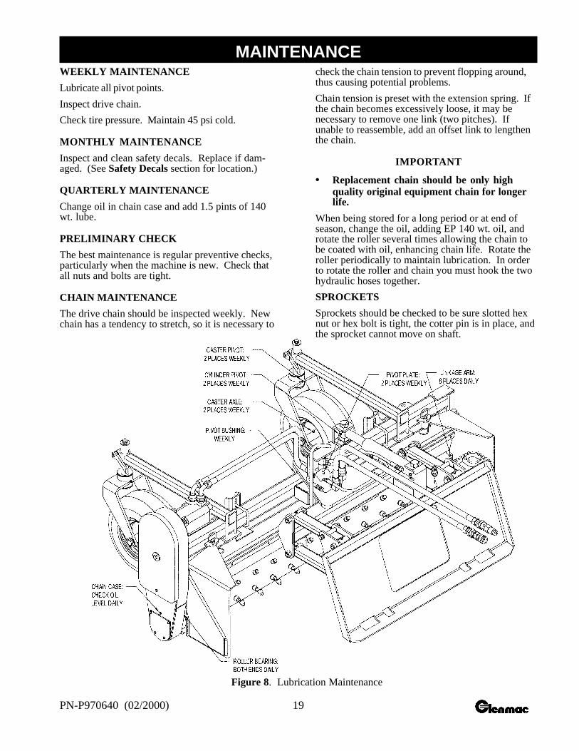
WEEKLY MAINTENANCE
Lubricate all pivot points.
Inspect drive chain.
Check tire pressure. Maintain 45 psi cold.
MONTHLY MAINTENANCE
Inspect and clean safety decals. Replace if dam-aged. (See Safety Decals section for location.)
QUARTERLY MAINTENANCE
Change oil in chain case and add 1.5 pints of 140wt. lube.
PRELIMINARY CHECK
The best maintenance is regular preventive checks,particularly when the machine is new. Check thatall nuts and bolts are tight.
CHAIN MAINTENANCE
The drive chain should be inspected weekly. Newchain has a tendency to stretch, so it is necessary to
check the chain tension to prevent flopping around,thus causing potential problems.
Chain tension is preset with the extension spring. Ifthe chain becomes excessively loose, it may benecessary to remove one link (two pitches). Ifunable to reassemble, add an offset link to lengthenthe chain.
IMPORTANT
• Replacement chain should be only highquality original equipment chain for longerlife.
When being stored for a long period or at end ofseason, change the oil, adding EP 140 wt. oil, androtate the roller several times allowing the chain tobe coated with oil, enhancing chain life. Rotate theroller periodically to maintain lubrication. In orderto rotate the roller and chain you must hook the twohydraulic hoses together.
SPROCKETS
Sprockets should be checked to be sure slotted hexnut or hex bolt is tight, the cotter pin is in place, andthe sprocket cannot move on shaft.
Figure 8. Lubrication Maintenance
MAINTENANCE

20 PN-P970640 (02/2000)
Problem Possible Cause Solution
Roller will not turn Hydraulic valve on skid-steer not See skid-steer Operator’s Manual forengaged auxiliary hydraulic operation procedure.
Relief valve setting on skid-steer not Have skid-steer dealer set relief valveproperly adjusted at correct pressure.
Worn, damaged, insufficient, or Repair or replace hydraulic pump.inadequate pump
Insufficient oil in system Service the skid-steer hydraulicreservoir.
Hose ends not completely engaged Check hose coupling andengage properly.
Air in hydraulic lines Cycle skid-steer auxiliary systemseveral times to remove air from lines.
Obstruction in hydraulic lines Replace obstructed or damaged line.
Obstruction between roller and barrier Reverse roller to clear obstruction.
Chain off Repair or replace chain.
Oil leaks. Worn or damaged seal Replace leaking seal.
Loose or damaged hoses Replace damaged hoses and secureloose hoses.
Loose or damaged connections Replace damaged hose connections andtighten loose fittings.
Worn or damaged housing Replace damaged housing.
Roller out of position Loosen bearing collar on frame and chaincase. Force roller toward chain case,then tighten bearing collars on chain caseand frame.
Angle cylinder will not Electrical failure Check electrical power circuit.extend or retract
Hydraulic system not activated Engage roller drive motor beforeattempting to move angle cylinder.
Angle cylinder will not Check-valve in manifold Repair or replace check-valve.hold position malfunctioning
Solenoid cartridge not returning Repair or replace solenoid cartridge.to closed position
TROUBLE SHOOTING
21PN-P970640 (02/2000)
The information in this section is written for dealerservice personnel. The repair described herein requiresspecial skills and tolls. If your shop is not properlytrained in this type of repair, you may be time and moneyahead to replace complete assemblies.
WARNING
• Never go underneath equipment lowered tothe ground or raised. Never place any part ofthe body underneath equipment or betweenmoveable parts even when the engine has beenturned off. Hydraulic system leak down,hydraulic system failures, mechanical failures,or movement of control levers can causeequipment to drop or rotate unexpectedly andcause severe injury or death.
• Service work does not require goingunderneath.
• Read Operator’s Manual for serviceinstructions or have done by a qualifieddealer.
CAUTION
• Always wear relatively tight and beltedclothing to avoid entanglement in movingparts. Wear sturdy, rough-soled work shoesand protective equipment for eyes, hair, hands,hearing, and head.
• Do not allow other people in the area whenoperating, attaching, removing, assembling, orservicing equipment.
• Do not modify or alter, or permit anyone elseto modify or alter, the equipment or any of itscomponents in any way.
• Do not disconnect hydraulic lines until allsystem pressure is relieved. Lower unit toground, stop engine, and operate all hydrauliccontrol levers.
• Ensure implement is properly attached,adjusted, and in good operating condition.
• Ensure all safety decals are installed. Replaceif damaged. (See Safety Decals section forlocation.)
• Ensure shields and guards are properlyinstalled and in good condition. Replace ifdamaged.
HYDRAULIC MOTOR
Removal
Remove chain from top sprocket. Then remove topsprocket by removing the hex bolt and washers.
Reassembly
Apply a liberal amount of silicone sealer to inside offlange. Attach hydraulic motor to chain case with fourbolts, flange, and nuts. Replace collar over shaft. Slidetop sprocket, sprocket teeth first, onto shaft. Use ma-chine bushings on the inside or outside of sprocket forproper alignment.
BEARINGS
Highest quality bearings are used on the power rake.Only triple-seal bearings are used on the roller whichoperates down in the dirt. Lubrication of bearings willvary considerably with conditions. As a rule, bearingsshould be under-lubricated rather than over-lubricated.Over-lubrication can cause seals to blow out.
IMPORTANT
• Replacement bearings should be only highquality original equipment bearings for longerlife.
Install new complete bearing housing if needed or justreplace the bearing insert.
The shafts should be straight, free of burrs, and up tosize. If shaft is worn, replace or have the shaft builtup to standard prior to completing assembly.
Protective Collars
The special protective collars protect bearings fromvine and wire wrap, and dirt buildup next to the bear-ing seal. The bearing protector is sandwiched ontothe shaft which rotates within a close clearance fromthe outer race of the bearing. Grease coming from thebearing oozes into the protecting collar, keeping dustand particles from entering the seal area, increasingthe bearing life.
Left Roller Bearing
Remove drive chain. Then remove lower sprocket byremoving cotter pin, slotted hex nut, and washers.
Remove the two bolts holding the chain case to theframe.
MAINTENANCE
22 PN-P970640 (02/2000)
NOTE: Have roller blocked up or supported and slidechain case and bearing off roller shaft.
Loosen bolt on the bearing tube that holds cartridgebearing in place. Remove bearing and O-ring.
To replace, reverse the procedure. Be sure all partsand wear surfaces are thoroughly clean and in goodcondition. Be sure O-ring is also in good condition.
When replacing bearing, first put O-ring on bearing.Apply a coat of grease on O-ring. Slide bearing inand apply moderate pressure on bearing so O-ring willseat and spread slightly, thus keeping the oil in chaincase from escaping through the bearing.
Right Roller Bearing
Remove the hex bolt and bearing cap from outside ofbearing.
Loosen bolt on the bearing tube that holds cartridgebearing in place. Pry bearing tube apart to free bear-ing assembly.
NOTE: Have roller blocked up or supported. Prybearing off of shaft and out of bearing holder.
To replace, reverse the procedure. Be sure all partsand wear surfaces are thoroughly clean and in goodcondition.
ROLLER REPLACEMENT
It will be necessary to have a lifting device or addi-tional help while removing and replacing the roller.The roller weighs approximately 150 lbs.
Remove upper and lower chain case covers.
Disconnect the two hydraulic hoses from motor. Pro-tect hose ends and fittings from being contaminated.
Remove tension spring and drive chain. Then removelower sprocket by removing cotter pin, slotted nut, andwashers. Remove the sleeve behind the sprocket youjust removed.
NOTE: Have the roller blocked up or supported.
Remove the two bolts holding chain case to frame andslide chain case, with hydraulic motor attached, off ofroller shaft. The roller bearing will stay in the chaincase.
NOTE: If chain case bearing is also being replaced,see Left Roller Bearing above.
Loosen the bolt on the bearing tube of the non-driveend, sliding roller and bearing out of frame.
Remove hex bolt, bearing cap, bearing, and protectivecollar from roller. On roller to be installed, place ma-chine bushing and protective collar against endplateof roller. Place bearing and bearing cap on roller.Clamp in place with hex bolt and lockwasher into endof roller shaft.
Slide roller and bearing into bearing tube on non-driveend of frame. Do not tighten bearing tube at this time.
Place spacer and protective collar from splined end ofremoved roller onto replacement roller. Apply seal-ant to bearing area of shaft. Slide chain case backonto roller and bolt to frame.
Replace sleeve, sprocket, and washers on driveshaft.Clamp solid with the 1" slotted jam nut. Check thatroller clears frame on both ends. Adjust if required.
Now, tighten 3/8" bolt in bearing tube on non-driveend of frame.
Reinstall chain and tension spring.
Replace lower cover, being careful not to pinch the O-ring. Fill the chain case with 1.5 pints of 140 wt. gearoil. Replace upper cover.
Run power rake and watch for any interference be-tween roller and frame.
MAINTENANCE
23PN-P970640 (02/2000)
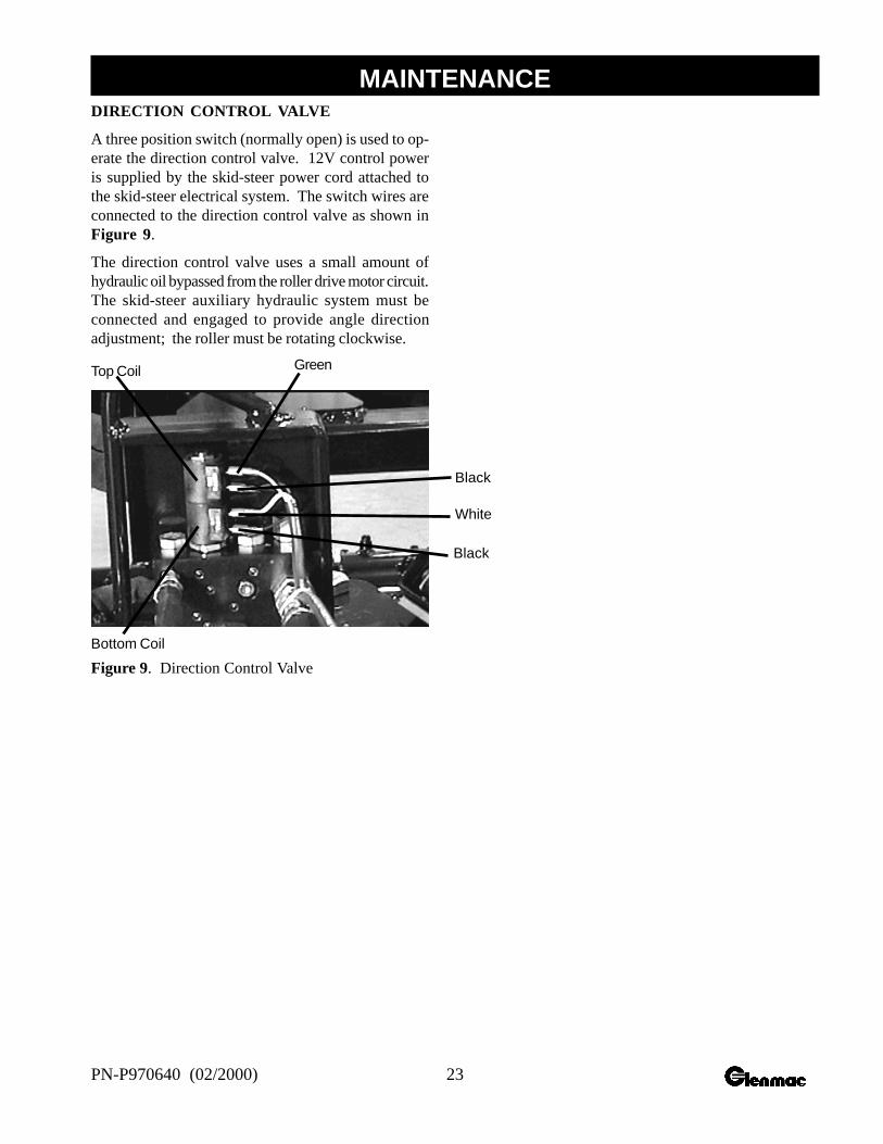
DIRECTION CONTROL VALVE
A three position switch (normally open) is used to op-erate the direction control valve. 12V control poweris supplied by the skid-steer power cord attached tothe skid-steer electrical system. The switch wires areconnected to the direction control valve as shown inFigure 9.
The direction control valve uses a small amount ofhydraulic oil bypassed from the roller drive motor circuit.The skid-steer auxiliary hydraulic system must beconnected and engaged to provide angle directionadjustment; the roller must be rotating clockwise.
Top Coil
Bottom Coil
Green
Black
White
Black
Figure 9. Direction Control Valve
MAINTENANCE
24 PN-P970640 (02/2000)
CAUTION
• Always wear relatively tight and beltedclothing to avoid entanglement in movingparts. Wear sturdy, rough-soled work shoesand protective equipment for eyes, hair, hands,hearing, and head.
WARNING
• Keep hands and body away from pressurizedlines. Use paper or cardboard, not body parts,to check for leaks. Wear safety goggles.Hydraulic fluid under pressure can easilypenetrate skin and will cause serious injuryor death.
• Make sure that all operating and servicepersonnel know that in the event hydraulicfluid penetrates the skin, it must be surgicallyremoved as soon as possible by a doctorfamiliar with this form of injury or gangrene,serious injury, or death will result.CONTACT A PHYSICIAN IMMEDIATELYIF FLUID ENTERS SKIN OR EYES. DONOT DELAY.
• Route hydraulic hoses carefully to preventdamage. Hoses must not be twisted, bentsharply, kinked, frayed, pinched, or come intocontact with any moving parts. Operatemoveable components through fulloperational range to check clearances.Replace any damaged hose immediately.
• Do not allow other people in the area whenoperating, attaching, removing, assembling,or servicing equipment.
• Do not modify or alter, or permit anyone elseto modify or alter, the equipment or any of itscomponents in any way.
SET-UP INSTRUCTIONS
The power rake is shipped partially assembled.Assembly will be easier if components are alignedand loosely assembled before tightening hardware.Recommended torque values for hardware arelocated on page 5.
Select a suitable working area. Refer to illustrations,accompanying text, parts lists, and exploded viewdrawings.
Tools Required
3/4 and 1-1/8 Combination wrenchs.
It is advisable to have a mechanical lifting device tofacilitate uncrating.
Unpacking Crate
Be careful of nails in boards when uncrating.
Remove top, sides, and ends of crate.
Remove attachment plate.
Remove endplates.
Remove gauge wheel assemblies.
Remove parts box.
Remove power rake from crate. Remove loose nailsfrom boards and dispose of crate according to localcodes.
ASSEMBLY
25PN-P970640 (02/2000)
ASSEMBLY PROCEDURE
For reference, front, back, left and right directionsare determined by sitting in the skid-steer operator’sseat.
Do not permit any bystanders within 10 feet ofpower rake during assembly.
WARNING
• Do not allow other people in the area whenoperating, attaching, removing, assembling,or servicing equipment.
• Avoid electrical system hazards.
• Never work on the electrical systemunless you are qualified and thoroughlyfamiliar with system details and the specialhandling requirements.
• Disconnect battery before working onelectrical system. Remove “ground” cablefirst. When reconnecting battery, connect“ground” cable last.
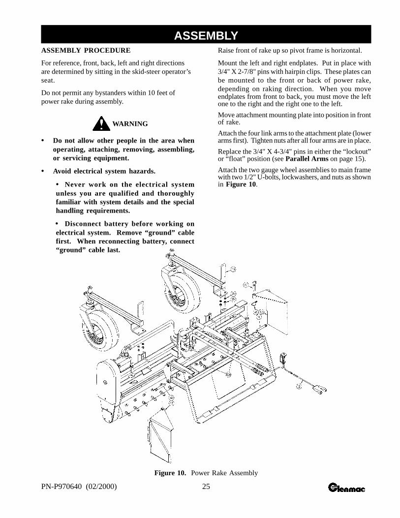
Raise front of rake up so pivot frame is horizontal.
Mount the left and right endplates. Put in place with3/4" X 2-7/8" pins with hairpin clips. These plates canbe mounted to the front or back of power rake,depending on raking direction. When you moveendplates from front to back, you must move the leftone to the right and the right one to the left.
Move attachment mounting plate into position in frontof rake.
Attach the four link arms to the attachment plate (lowerarms first). Tighten nuts after all four arms are in place.
Replace the 3/4" X 4-3/4" pins in either the “lockout”or “float” position (see Parallel Arms on page 15).
Attach the two gauge wheel assemblies to main framewith two 1/2" U-bolts, lockwashers, and nuts as shownin Figure 10.
Figure 10. Power Rake Assembly
ASSEMBLY
26 PN-P970640 (02/2000)
Install skid-steer power cord by connecting the red wireto a positive 12 volt power source and the white wireto ground. The power cord includes an in-line fuseand spring-loaded battery clamps. The red (positive)cable is fused and should always be connected to thepositive side of the battery to ensure proper operationof the electrical circuit. Be careful when routing thecable that sharp edges or moving parts will not dam-age it.
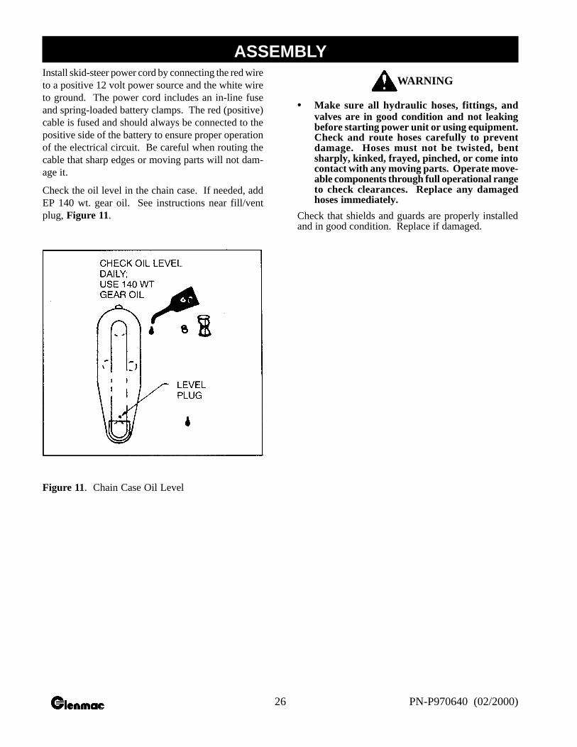
Check the oil level in the chain case. If needed, addEP 140 wt. gear oil. See instructions near fill/ventplug, Figure 11.
Figure 11. Chain Case Oil Level
WARNING
• Make sure all hydraulic hoses, fittings, andvalves are in good condition and not leakingbefore starting power unit or using equipment.Check and route hoses carefully to preventdamage. Hoses must not be twisted, bentsharply, kinked, frayed, pinched, or come intocontact with any moving parts. Operate move-able components through full operational rangeto check clearances. Replace any damagedhoses immediately.
Check that shields and guards are properly installedand in good condition. Replace if damaged.
ASSEMBLY
27PN-P970640 (02/2000)
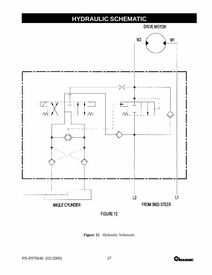
Figure 12. Hydraulic Schematic
HYDRAULIC SCHEMATIC
28 PN-P970640 (02/2000)
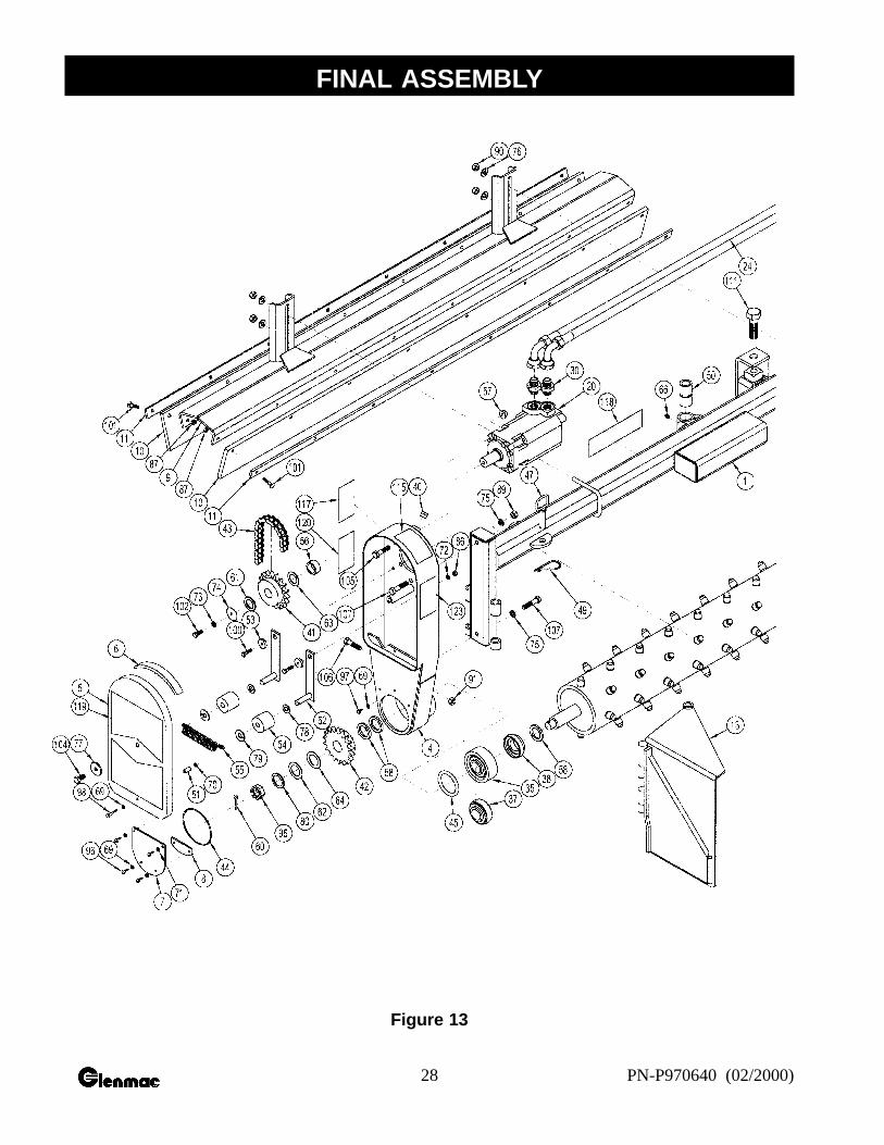
Figure 13
FINAL ASSEMBLY
29PN-P970640 (02/2000)
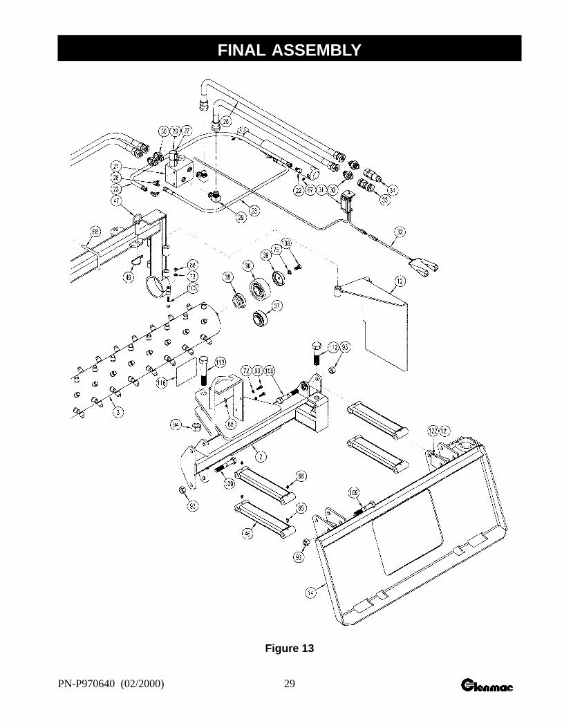
Figure 13
FINAL ASSEMBLY
30 PN-P970640 (02/2000)
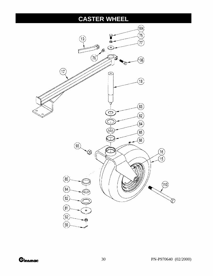
CASTER WHEEL

31PN-P970640 (02/2000)
ITEM QYT PART NO. DESCR IPTION ITEM QYT PART NO. DESCRIPTION
PARTS LIST
1 1 M6803 MAIN FRAME2 1 M6809 PIVOT FRAME3 1 M6775 CARBIDE TOOTH ROLLER4 1 M6608 CHAIN CASE5 1 M6618 COVER6 1 M6642 COVER SEAL7 1 M8241 LOWER COVER8 1 M8272 COVER TAB9 1 M6796 BARRIER MOUNT
10 2 M6427 BARRIER11 2 M6428 BARRIER STRAP12 1 M6624 END PLATE RIGHT13 1 M6625 END PLATE LEFT14 1 M6812 ATTACHMENT MOUNT15 2 P756100 WHEEL & TIRE16 2 M6817 CASTER FORK17 2 M16012 CASTER SUPPORT ARM18 2 M16011 CASTER SHAFT19 2 M6415 HANDLE20 1 P350200 HYDRAULIC MOTOR 109-111721 1 P243000 HYDRAULIC MANIFOLD22 1 P257500 2" X 8" HYDRAULIC CYLINDER23 2 P246000 -4 HOSE X 27" 4FJX-6FJX24 2 P255685 -10 HOSE X 44" 12FJX-12FJX90°25 2 P255736 -10 HOSE X 66" 12FJX-12FJX26 1 P243001 SOLENOID CARTRIDGE27 2 P290304 SOLENOID COIL28 2 P261400 ELBOW –4MB-4MJ90°29 2 P276480 ELBOW 12MJ-12MB90°30 6 P276450 ADAPTER 12MJ-12MB31 1 M6725 SWITCH ASSEMBLY32 1 M6726 CABLE ASSEMBLY33 1 P272670 FEMALE FLAT FACE COUPLER34 1 P272671 MALE FLAT FACE COUPLER35 1 M6687 BEARING ASSEMBLY DRIVE36 1 M6688 BEARING ASSEMBLY IDLE37 2 P010400 1-1/2" BEARING INSERT38 2 P015308 1-1/2" NON LOCK COLLAR39 1 P015307 1-1/2" BEARING CAP40 1 P278001 VENT PLUG41 1 P661804 18 TOOTH SPROCKET 1-1/4" SPLINE42 1 P661805 18 TOOTH SPROCKET 1-1/2" SPLINE43 1 M6641 DRIVE CHAIN #60H-75P44 1 P500202 O-RING 3/32" X 4-3/4"45 1 P500203 O-RING 3/8" X 2-5/8"46 2 M6795 LINK ARM47 2 M6442 3/4" X 2-1/2" CLEVIS PIN48 2 P120210 3/4" X 3-7/8" CLEVIS PIN49 2 P622600 HAIR PIN CLIP50 1 M6637 PIVOT BUSHING51 1 P481010 BUSHING52 2 M6629 TENSION ARM53 2 M6630 PIVOT BUSHING54 2 M6628 IDLER ROLLER55 1 P604605 EXTENSION SPRING56 1 M6634 COLLAR57 4 P155851 1/2" SERRATED FLANGE NUT58 3 M6757 SPACER .218 LONG59 2 P116204 1/8" X 1" COTTER PIN60 1 P116306 3/16" X 1-1/2" COTTER PIN61 1 P855120 10 GA X 1-1/4" MACHINE BUSHING62 1 P855124 10 GA X 1-1/2" MACHINE BUSHING63 1 P855320 14 GA X 1-1/4" MACHINE BUSHING64 1 P855324 14 GA X 1-1/2" MACHINE BUSHING65 5 P620000 1/4-28 X 45° GREASE FITTING
66 8 P620200 1/4-28 STR GREASE FITTING67 2 P620500 1/4 NPT STR GREASE FITTING68 2 P128318 U-BOLT 1/2" X 3" X 4"69 4 P500300 1/4" O-RING WASHER70 1 P500302 1/4" RUBBER FACE WASHER71 2 P851104 1/4" LOCK WASHER72 4 P851105 5/16" LOCK WASHER73 2 P851106 3/8" LOCK WASHER74 1 M5009-2 3/8" X 1-3/4" FLAT WASHER75 9 P851108 1/2" LOCK WASHER76 6 P852608 1/2" HARD WASHER77 3 M5009-5 3/16" X 1/2" X 1-3/4" WASHER78 2 P850609 9/16" FLAT WASHER79 2 M6756 PINNED WASHER80 1 P851616 1" HEAVY HARD WASHER81 2 M6223 WASHER82 4 P852200 FELT WASHER83 2 P850620 1-1/4" FLAT WASHER84 4 P760300 BEARING CONE85 4 P760500 BEARING CUP86 2 P150500 5/16" HEX NUT87 16 P155350 5/16" CENTER LOCK NUT88 1 P150600 3/8" HEX NUT89 5 P150800 1/2" HEX NUT90 4 P158005 1/2" NYLOCK NUT91 1 P155852 1/2"-20 LOCK NUT92 2 P158006 1/2"-13 SLOTTED HEX NUT93 10 P157120 3/4" CENTRE NUT94 1 P156401 1" LOCK NUT95 1 P156402 1" SLOTTED HEX NUT96 4 P110901 1/4" X 3/4" BUTTON HEAD SCREW97 1 P100402 1/4" X 1/2" HEX BOLT98 1 P100406 1/4" X 1-1/2" HEX BOLT99 2 P100504 5/16" X 1" HEX BOLT
100 2 P100505 5/16" X 1-1/4" HEX BOLT101 16 P104506 5/16" X 1-1/2" CARRIAGE BOLT102 1 P100604 3/8" X 1" HEX BOLT103 1 P100608 3/8" X 2" HEX BOLT104 3 P100804 1/2" X 1" HEX BOLT105 4 P100808 1/2" X 2" HEX BOLT106 3 P102808 1/2" X 2" FINE THD HEX BOLT107 2 P100812 1/2" X 3" HEX BOLT108 1 P102804 1/4" X 1-1/4" FINE THD HEX BOLT109 8 M6816 3/4" X 4-1/2" HEX BOLT110 2 P103138 3/4" X 9-1/2" CASTER BOLT111 1 M6815 1" X 3-1/8" HEX BOLT112 1 P101616 1" X 4" HEX BOLT113 1 P101622 1" X 5-1/2" FINE THD HEX BOLT114 2 P128324 1/2" U-BOLT115 1 P970300 DECAL: WARNING CHAIN116 1 P970250 DECAL: WARNING ROLLER117 1 P970003 DECAL: LUBRICATION118 1 P975801 DECAL: HARLEY (WHITE)119 1 P975917 DECAL: S-6 BOX RAKE120 1 P975602 DECAL: GAGE WHEEL121 1 P970011 DECAL: LOCK-OUT122 1 P970010 DECAL: LOCK-OUT123 1 P970004 DECAL: WARNING LIFT124 2 P126207 7/16 LYNCH PIN
32 PN-P970640 (02/2000)
GLENMAC, INC. warrants, to the original purchaser of the HARLEY POWER BOX RAKE®, that it will repairor replace any manufactured parts thereof found to be, under normal use, defective in factory material orworkmanship for six (6) months from the date of purchase.
This warranty shall become void if in the judgment of GLENMAC, INC. the equipment has been subject tomisuse, negligence, alteration, damaged by accident or lack of required maintenance, or if the product has beenused for a purpose for which it was not intended. Wear items such as, but not limited to, rollers and chain cases willnot be covered under warranty.
This warranty does not apply to hydraulic motor, electric actuator, tires, bearing, sprockets, or any other tradeaccessories not manufactured by GLENMAC, INC. Buyer must rely solely on the existing warranty, if any, ofthese respective manufacturers.
This warranty will become void if a valid warranty registration card is not received by GLENMAC, INC. at itsJAMESTOWN, ND office within ten (10) days of original purchase.
Certain HARLEY dealers provide Limited Warranty replacement service. We would suggest that you contactyour selling dealer and attempt to resolve your warranty service problem locally prior to contacting our homeoffice. Any questions concerning warranty service can be directed to our Customer Service Department at POBox 2135 Jamestown, ND, 58402, or call (701) 252-9300.
THERE IS NO OTHER EXPRESSED OR IMPLIED WARRANTY ON THIS PRODUCT OR ON ITSMERCHANTABILITY OR ON ITS FITNESS. TO THE EXTENT ALLOWED BY LAW, NEITHERGLENMAC, INC. NOR THE SELLING HARLEY DEALER SHALL HAVE ANY RESPONSIBILITY FORLOSS OF USE OF THE PRODUCT, LOSS OF TIME, INCONVENIENCE, COMMERCIAL LOSS ORCONSEQUENTIAL DAMAGES.
Some states do not allow limitations on the exclusion or limitation of incidental or consequential damages, thereforethe above limitations may not apply to you.
This warranty gives you specific legal rights that vary from state to state.
Please enter information below and SAVE FOR FUTURE REFERENCE.
Date Purchased: ______________ From (Dealer): ________________
Model Number: _______________ Serial Number:________________
Glenmac, Inc.1805 2nd Avenue SWJamestown, ND 58401
701-252-9300 tel701-252-1978 fax701-252-9259 parts fax
LIMITED WARRANTY
S.6

PN-P970640 (02/2000)SN: S60G001
by
Glenmac Inc1805 2nd Avenue SWJamestown ND 58401
701-252-9300 tel701-252-1978 fax701-251-9259 parts fax