Embed Size (px)
Citation preview

S6700 Series Ethernet Switches
Hardware Description
Issue 01
Date 2012-12-08
HUAWEI TECHNOLOGIES CO., LTD.

Copyright © Huawei Technologies Co., Ltd. 2012. All rights reserved.No part of this document may be reproduced or transmitted in any form or by any means without prior writtenconsent of Huawei Technologies Co., Ltd. Trademarks and Permissions
and other Huawei trademarks are trademarks of Huawei Technologies Co., Ltd.All other trademarks and trade names mentioned in this document are the property of their respective holders. NoticeThe purchased products, services and features are stipulated by the contract made between Huawei and thecustomer. All or part of the products, services and features described in this document may not be within thepurchase scope or the usage scope. Unless otherwise specified in the contract, all statements, information,and recommendations in this document are provided "AS IS" without warranties, guarantees or representationsof any kind, either express or implied.
The information in this document is subject to change without notice. Every effort has been made in thepreparation of this document to ensure accuracy of the contents, but all statements, information, andrecommendations in this document do not constitute a warranty of any kind, express or implied.
Huawei Technologies Co., Ltd.Address: Huawei Industrial Base
Bantian, LonggangShenzhen 518129People's Republic of China
Website: http://enterprise.huawei.com
Issue 01 (2012-12-08) Huawei Proprietary and ConfidentialCopyright © Huawei Technologies Co., Ltd.
i

Contents
1 About This Document..................................................................................................................1
2 Version Description......................................................................................................................3
3 Chassis.............................................................................................................................................43.1 Chassis Overview...............................................................................................................................................53.2 Naming Rules.....................................................................................................................................................53.3 S6700..................................................................................................................................................................6
3.3.1 Version Mapping.......................................................................................................................................63.3.2 Appearance and Structure..........................................................................................................................73.3.3 Indicator Description.................................................................................................................................83.3.4 Port Description.......................................................................................................................................113.3.5 Power Supply...........................................................................................................................................123.3.6 Heat Dissipation......................................................................................................................................133.3.7 Specifications...........................................................................................................................................14
4 Power Module..............................................................................................................................174.1 500 W AC Power Module................................................................................................................................184.2 500 W DC Power Module................................................................................................................................20
5 Fan Module...................................................................................................................................245.1 CX7E1FANA Fan Module...............................................................................................................................25
6 Cables.............................................................................................................................................286.1 Ground Cable....................................................................................................................................................296.2 Stack Cable.......................................................................................................................................................296.3 Optical Fiber.....................................................................................................................................................306.4 Network Cable..................................................................................................................................................346.5 DC Power Cable...............................................................................................................................................366.6 AC Power Cable...............................................................................................................................................386.7 Console Cable...................................................................................................................................................38
7 Optical Module............................................................................................................................417.1 Basic Concepts.................................................................................................................................................427.2 SFP/eSFP Modules...........................................................................................................................................447.3 SFP+ Modules..................................................................................................................................................48
S6700 Series Ethernet SwitchesHardware Description Contents
Issue 01 (2012-12-08) Huawei Proprietary and ConfidentialCopyright © Huawei Technologies Co., Ltd.
ii

7.4 Huawei Certification.........................................................................................................................................51
S6700 Series Ethernet SwitchesHardware Description Contents
Issue 01 (2012-12-08) Huawei Proprietary and ConfidentialCopyright © Huawei Technologies Co., Ltd.
iii

1 About This Document
Intended Audience
This document provides an overall description of the S6700, which helps you obtain detailedinformation about each chassis, power module, fan module, cable, and optical module.
This document is intended for:
l Network planning engineers
l Hardware installation engineers
l Commissioning engineers
l On-site maintenance engineers
l System maintenance engineers
Symbol Conventions
The symbols that may be found in this document are defined as follows:
Symbol Description
DANGERAlerts you to a high risk hazard that could, if not avoided,result in serious injury or death.
WARNINGAlerts you to a medium or low risk hazard that could, if notavoided, result in minor or moderate injury.
CAUTIONAlerts you to a potentially hazardous situation that could, ifnot avoided, result in equipment damage, data loss,performance deterioration, or unanticipated results.
TIP Indicates a tip that may help you solve a problem or savetime.
NOTE Provides additional information to emphasize or supplementimportant points in the main text.
S6700 Series Ethernet SwitchesHardware Description 1 About This Document
Issue 01 (2012-12-08) Huawei Proprietary and ConfidentialCopyright © Huawei Technologies Co., Ltd.
1

Change HistoryChanges between document issues are cumulative. The latest document issue contains allchanges made to previous issues.
Changes in Issue 01 (2012-12-08)Initial commercial release.
S6700 Series Ethernet SwitchesHardware Description 1 About This Document
Issue 01 (2012-12-08) Huawei Proprietary and ConfidentialCopyright © Huawei Technologies Co., Ltd.
2

2 Version Description
Available ModelsTable 2-1 lists the switch models available in V200R002C00.
Table 2-1 Switch models available in V200R002C00
Series Model Maximum Number of Interfaces
S6700 S6700-24-EI 24There are twenty-four 10GE SFP+ optical interfaces(working in auto-sensing mode and changing to GEinterfaces).
S6700-48-EI 48There are forty-eight 10GE SFP+ optical interfaces(working in auto-sensing mode and changing to GEinterfaces).
Available Power ModulesTable 2-2 lists the power modules available in V200R002C00.
Table 2-2 Power modules available in V200R002C00
Power Module Type Power Module
AC power module 500 W AC Power Module
DC power module 500 W DC Power Module
S6700 Series Ethernet SwitchesHardware Description 2 Version Description
Issue 01 (2012-12-08) Huawei Proprietary and ConfidentialCopyright © Huawei Technologies Co., Ltd.
3
3 Chassis
About This Chapter
3.1 Chassis Overview
3.2 Naming Rules
3.3 S6700
S6700 Series Ethernet SwitchesHardware Description 3 Chassis
Issue 01 (2012-12-08) Huawei Proprietary and ConfidentialCopyright © Huawei Technologies Co., Ltd.
4

3.1 Chassis Overview
The S6700 series Ethernet switches (S6700 for short) provide the access, aggregation, and datatransport functions. They are developed by Huawei to meet the requirements for reliable accessand aggregation and high-quality transmission of multiple services on enterprise networks. TheS6700 uses an integrated hardware platform. The S6700 hardware consists of the chassis, powermodule, fan module, and switch control unit (SCU).
The S6700 switches include S6700-24-EI and S6700-48-EI.
3.2 Naming Rules
Figure 3-1 shows naming rules of case-shaped switches.
Figure 3-1 Naming rules of case-shaped switches
S5700S-52P-PWR-LI-24S-ACABC D E F G H I J K
S6700-24-EIABC D F I
NOTEThe device names in this figure are used as examples and do not represent specified devices.
Table 3-1 lists the naming rules of case-shaped switches.
Table 3-1 Naming rules of case-shaped switches
Identifier
Description
A Switch
B l 6: 10GE downlink portsl 5: 1000M downlink portsl 3: Layer 3 switch with 100M downlink portsl 2: Layer 2 switch with 100M downlink ports
C 7: Enterprise series switch
S6700 Series Ethernet SwitchesHardware Description 3 Chassis
Issue 01 (2012-12-08) Huawei Proprietary and ConfidentialCopyright © Huawei Technologies Co., Ltd.
5

Identifier
Description
D Product sub-series (such as 00, 10)
E Resale modelNOTE
If the letter S is not displayed, this model is a non-resale model.
F Maximum number of portsNOTE
On an S5710-EI switch, this field indicates the number of fixed ports on the switch.
G Uplink port type:l C: The switch supports cards. Ports of cards function as uplink ports.l X: The switch has fixed 10GE uplink ports.l TP: The switch has combo ports that can function as optical and electrical ports.l P: The switch has uplink optical ports.NOTE
If this field is not displayed, the switch has no uplink port.
H Power over Ethernet (PoE) modelNOTE
If this field is not displayed, the switch does not support PoE.
I Software version typel LI: indicates the simplified version.l SI: indicates the standard version, supporting basic features.l EI: indicates the enhanced version, supporting enhanced features.l HI: indicates the advanced version, supporting high-performance operation,
administration, and maintenance (OAM) and built-in real-time clock (RTC).
J Downlink port type. The field 24S indicates that 24 downlink ports of the switch areoptical ports.NOTE
If the S5700 does not contain this field, all the downlink ports of the switch are electrical ports.The S6700 does not contain this field because all its ports are downlink optical ports.
K Powering mode:l AC: indicates alternating current power.l DC: indicates direct current power.
3.3 S6700
3.3.1 Version MappingTable 3-2 lists the mapping between the S6700 chassis and software versions.
S6700 Series Ethernet SwitchesHardware Description 3 Chassis
Issue 01 (2012-12-08) Huawei Proprietary and ConfidentialCopyright © Huawei Technologies Co., Ltd.
6

Table 3-2 Mapping between the S6700 chassis and software versions
Series Model Available Version
S6700 S6700-24-EI V100R006C00 and laterversions
S6700-48-EI V100R006C00 and laterversions
3.3.2 Appearance and Structure
Front ViewTable 3-3 shows the front view of the S6700 chassis.
Table 3-3 Front view of the S6700 chassis
Model Image
S6700-24-EI 1
4 5
3
S6700-48-EI 2
4 5
3
1. Twenty-four10GE SFP+Ethernet opticalports
NOTEThe ports support the1000BASE-T SFPcopper module.
2. Forty-eight 10GESFP+ Ethernetoptical ports
NOTEThe ports support the1000BASE-T SFPcopper module.
3. One console port 4. One ETHmanagement port
S6700 Series Ethernet SwitchesHardware Description 3 Chassis
Issue 01 (2012-12-08) Huawei Proprietary and ConfidentialCopyright © Huawei Technologies Co., Ltd.
7

5. One USB port
NOTEThe USB port is usedto connect USB disksfor deployment,configuration filetransfer, and fileupgrade.
Rear ViewTable 3-4 shows the rear view of the S6700 chassis.
Table 3-4 Rear view of the S6700 chassis
Model Image
S6700-24-EIS6700-48-EI
31 42
1. Ground screw
NOTEIt is used with aground cable.
2. ESD jack
NOTEWhen you install ormaintain an S6700chassis, wear an ESDwrist strap and insert theother end of the ESDwrist strap into this ESDjack.
3. Fan module slot
NOTEAvailable fans:CX7E1FANA FanModule
4. Power module slot
NOTEAvailable powermodules:
l 500 W AC PowerModule
l 500 W DC PowerModule
3.3.3 Indicator Description
S6700-24-EINOTE
Symbols and meanings of indicators on the S6700-48-EI are the same as those on the S6700-24-EI.
Figure 3-2 Indicators on the S6700-24-EI
2
3
4
5
16
S6700 Series Ethernet SwitchesHardware Description 3 Chassis
Issue 01 (2012-12-08) Huawei Proprietary and ConfidentialCopyright © Huawei Technologies Co., Ltd.
8

Table 3-5 Description of indicators on the S6700-24-EI
Number
Indicator/Button
Color Description
1 PWR1: powersupply indicator
Off The PWR1 slot has no power moduleinstalled, or the power module is faultywhen a single power module is used.
Green Steady on: The power module is workingproperly.
Red Steady on: Any of the following situationsoccur:l Dual power modules are installed, but
not switched on.l Dual power modules are installed, but
receive no input power.l The power modules are faulty.
2 PWR2: powersupply indicator
Off The PWR2 slot has no power moduleinstalled, or the power module is faultywhen a single power module is used.
Green Steady on: The power module is workingproperly.
Red Steady on: Any of the following situationsoccur:l Dual power modules are installed, but
not switched on.l Dual power modules are installed, but
receive no input power.l The power modules are faulty.
3 SYS: systemstatus indicator
Off The system is not running.
Green l Steady on: The system is not operatingproperly or is starting.
l Blinking: The system is operatingproperly.
Orange Steady on: The system is performing self-check during startup.
Red Steady on: After registering, the systemdoes not operate properly, or a fan alarm,or temperature alarm is generated.
4 MODE: modeindicator
Off The service port indicators are in thedefault mode (STAT).
S6700 Series Ethernet SwitchesHardware Description 3 Chassis
Issue 01 (2012-12-08) Huawei Proprietary and ConfidentialCopyright © Huawei Technologies Co., Ltd.
9

Number
Indicator/Button
Color Description
Green Steady on: The service port indicatorsindicate the port speed. After 45 seconds,the service port indicators automaticallyrestore to STAT mode.
Red Steady on: The service port indicatorsindicate the stack ID of the switch. After45 seconds, the service port indicatorsautomatically restore to STAT mode.
5 Mode switchbutton
- l When you press the button once, themode indicator turns green and theservice port indicators show the speedof each port.
l When you press the button for a secondtime, the mode indicator turns red andthe service port indicators show thestack status.
l When you press the button for a thirdtime, the mode indicator turns off.
If you do not press the button within 45seconds, the mode indicator restores toSTAT mode.
6 Service portindicator
The meaning of the service port indicator varies with thecurrent mode. For details, see Table 3-6.
Table 3-6 Description of service port indicators in different modes
Display Mode Color Meaning
STAT mode Off The port is not connected or has been shutdown.
Green l Steady on: The port is connected.l Blinking: The interface is sending or
receiving data.
SPED mode Off The port is not connected or has been shutdown.
Green l Steady on: The port is operating at aspeed of 1000 Mbit/s.
l Blinking: The port is operating at aspeed of 10 Gbit/s.
STCK mode Off Port indicators do not show the stack ID ofthe switch.
S6700 Series Ethernet SwitchesHardware Description 3 Chassis
Issue 01 (2012-12-08) Huawei Proprietary and ConfidentialCopyright © Huawei Technologies Co., Ltd.
10

Display Mode Color Meaning
Green l Steady on:The switch is not a master switch:– If the indicator of a port is steady on,
the number of this port is the stackID of the switch.
– If the first nine port indicators of theswitch are steady on, the stack ID ofthe switch is 0.
l Blinking:The switch is a master switch:– If the indicator of a port is blinking,
the number of this port is the stackID of the switch.
– If the first nine port indicators of theswitch are blinking, the stack ID ofthe switch is 0.
3.3.4 Port Description
10GE SFP+ Ethernet Optical PortA 10GE SFP+ Ethernet optical port supports auto-sensing to 1000 Mbit/s. It receives and sendsservices at a speed of 1 Gbit/s or 10 Gbit/s. Table 3-7 describes the attributes of a 10GE SFP+Ethernet optical port.
Table 3-7 Attributes of a 10GE SFP+ Ethernet optical port
Attribute Description
Connector type LC/PC
Optical portattribute
Depending on the optical module used on the port (see 7.2 SFP/eSFPModules and 7.3 SFP+ Modules)
Standardscompliance
IEEE802.3ae
Frame format Ethernet_II, Ethernet_SAP, Ethernet_SNAP
Network protocol IP
Working mode GE/10GE auto-sensingFull duplex
S6700 Series Ethernet SwitchesHardware Description 3 Chassis
Issue 01 (2012-12-08) Huawei Proprietary and ConfidentialCopyright © Huawei Technologies Co., Ltd.
11

Console PortThe console port is connected to a console for on-site configuration. The port must use a consolecable. The console port is used when a switch is powered on for the first time. Table 3-8 describesthe attributes of the console port.
Table 3-8 Attributes of a console port
Attribute Description
Connector type RJ45
Standardscompliance
RS-232
Working mode Duplex Universal Asynchronous Receiver/Transmitter (UART)
Baud rate 9600 bit/s to 115200 bit/sDefault value: 9600 bit/s
Data equipmenttype
Data circuit-terminating equipment (DCE)
ETH Management PortAn ETH management port is connected to the network port of a configuration terminal ornetwork management workstation to set up the on-site or remote configuration environment.The port must use a network cable. Table 3-9 describes the attributes of an ETH managementport.
Table 3-9 Attributes of an ETH management port
Attribute Description
Connector type RJ45
Standardscompliance
IEEE802.3
Working mode 10/100 Mbit/s auto-sensingFull duplex
Maximumtransmissiondistance
100 m
3.3.5 Power Supply
Power Supply ConfigurationOn the S6700 switch, one or two power modules can be configured.
S6700 Series Ethernet SwitchesHardware Description 3 Chassis
Issue 01 (2012-12-08) Huawei Proprietary and ConfidentialCopyright © Huawei Technologies Co., Ltd.
12

When two power modules are used, they work in 1+1 backup mode to provide power for thedevice. An AC power module and a DC power module cannot be configured at the same time.
Figure 3-3 shows the power supply mode of dual DC power modules. After DC power istransmitted to the PWR module, the PWR module provides -53 V output voltage, and themotherboard provides power for the entire device.
Figure 3-3 Power supply mode of dual DC power modules
PWR1
NEG RTN
Motherboard
GND-53V
PWR2
NEG RTN
NEG: Power cable RTN: Power return cable GND: Ground cable
Figure 3-4 shows the power supply mode of dual AC power modules. After AC power istransmitted to the PWR module, the PWR module provides -53 V output voltage, and themotherboard provides power for the entire device.
Figure 3-4 Power supply mode of dual AC power modules
PWR1
L N
Motherboard
GND-53V
PGND
PWR2
L N PGND
L: Live line N: Neutral wire PGND: Protective ground cable GND: Ground cable RTN: Power return cable
3.3.6 Heat Dissipation
Table 3-10 describes the heat dissipation modes of the S6700.
S6700 Series Ethernet SwitchesHardware Description 3 Chassis
Issue 01 (2012-12-08) Huawei Proprietary and ConfidentialCopyright © Huawei Technologies Co., Ltd.
13

Table 3-10 S6700 heat dissipation mode
HeatDissipationMode
Model Air Flow in the Chassis
Forcibleheatdissipation
l S6700-24-EIl S6700-48-EI
The air flows in from the left or right and flows out from therear.
3.3.7 Specifications
Table 3-11 lists specifications of the S6700.
Table 3-11 Specifications of the S6700
Item Description
CPU 1 GHz dominant frequency
Packet forwardingcapacity(1 Gbps = 1.5 Mpps)
l S6700-24-EI: 360 Mppsl S6700-48-EI: 720 Mpps
DDR memory 512 MB
Flash memory 64 MB
Mean time betweenfailures (MTBF)
l S6700-24-EI: 34.54 yearsl S6700-48-EI: 33.76 years
Mean time to repair(MTTR)
2 hours
Surgeprotection
Serviceportprotection
-
S6700 Series Ethernet SwitchesHardware Description 3 Chassis
Issue 01 (2012-12-08) Huawei Proprietary and ConfidentialCopyright © Huawei Technologies Co., Ltd.
14

Item Description
Powersupplyprotection
l AC: ±2 kV in differential mode; ±4 kV in common model DC: ±1 kV in differential mode; ±2 kV in common mode
Dimensions (W x Dx H)
442.0 mm x 420.0 mm x 43.6 mm
Weight Fullyloaded
≤ 8.5 kg
Emptyloaded
≤ 5 kg
Stack port 10GE SFP+ port (A maximum of eight 10GE SFP+ ports is supported.)
RPS Not supported
PoE Not supported
InputDCvoltage
Ratedinputvoltagerange
-48 V DC to -60 V DC
Maximumvoltagerange
-38.4 V DC to -72 V DC
InputACvoltage
Ratedinputvoltagerange
100 V AC to 240 V AC; 50/60 Hz
Maximumvoltagerange
90 V AC to 264 V AC; 47 Hz to 63 Hz
Maximum power(fully loaded)
l S6700-24-EI: 153.6 Wl S6700-48-EI: 240 W
Temperature
Operatingtemperature
-5°C to +50°C (at 0 m to 1800 m altitude)NOTE
When the altitude is between 1800 m and 3000 m, the operating temperaturereduces 1°C every time the altitude increases 220 m.
Storagetemperature
-40°C to +70°C
S6700 Series Ethernet SwitchesHardware Description 3 Chassis
Issue 01 (2012-12-08) Huawei Proprietary and ConfidentialCopyright © Huawei Technologies Co., Ltd.
15

Item Description
Noise under normaltemperature (23°C,Sound Power)
Less than 55 dBA
Relative humidity 10% RH to 90% RH, non-condensing
Operating altitude 0 m to 3000 m
EMC l CISPR22 Class Bl CISPR24l EN55022 Class Bl EN50024l ETSI EN 300 386 Class Bl CFR 47 FCC Part 15 Class Al ICES 003 Class Bl AS/NZS CISPR22 Class Bl VCCI Class Bl IEC61000-6-2l IEC61000-6-4l IEC61000-4-2l ITU-T K 20l ITU-T K 21l ITU-T K 44
Environmentalstandard
l RoHSl REACH
Security l IEC 60950-1l EN 60950-1/A11/A12l UL 60950-1l CSA C22.2 No 60950-1l AS/NZS 60950.1
Laser safety l IEC60825-1l IEC60825-2l EN60825-1l EN60825-2
S6700 Series Ethernet SwitchesHardware Description 3 Chassis
Issue 01 (2012-12-08) Huawei Proprietary and ConfidentialCopyright © Huawei Technologies Co., Ltd.
16

4 Power Module
About This Chapter
CAUTIONl Only the power modules of the same power can be used on an S6700.l Power off the S6700 before removing the power modules. Do not operate the power modules
when the S6700 is running.l A device cannot use an AC power supply unit and a DC power supply unit simultaneously.l Before powering off the S6700, shut down all its power supply units.
4.1 500 W AC Power Module
4.2 500 W DC Power Module
S6700 Series Ethernet SwitchesHardware Description 4 Power Module
Issue 01 (2012-12-08) Huawei Proprietary and ConfidentialCopyright © Huawei Technologies Co., Ltd.
17
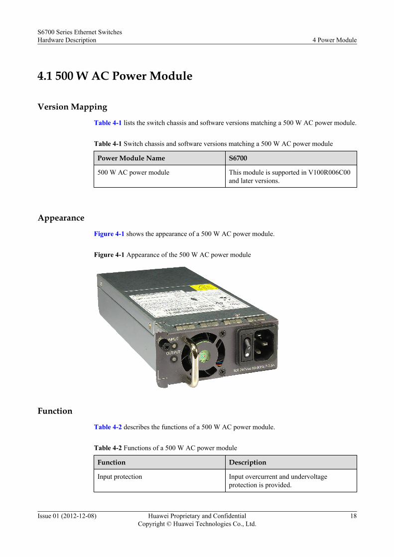
4.1 500 W AC Power Module
Version Mapping
Table 4-1 lists the switch chassis and software versions matching a 500 W AC power module.
Table 4-1 Switch chassis and software versions matching a 500 W AC power module
Power Module Name S6700
500 W AC power module This module is supported in V100R006C00and later versions.
Appearance
Figure 4-1 shows the appearance of a 500 W AC power module.
Figure 4-1 Appearance of the 500 W AC power module
Function
Table 4-2 describes the functions of a 500 W AC power module.
Table 4-2 Functions of a 500 W AC power module
Function Description
Input protection Input overcurrent and undervoltageprotection is provided.
S6700 Series Ethernet SwitchesHardware Description 4 Power Module
Issue 01 (2012-12-08) Huawei Proprietary and ConfidentialCopyright © Huawei Technologies Co., Ltd.
18

Function Description
Output protection Output undervoltage, overvoltage,overcurrent, and short-circuit protection isprovided.
EMC filter -
Overtemperature protection -
Surge protection -
NOTEThe 500 W AC power supply on the S6700 is a PoE power supply. However, it can only be used as a systempower supply on the S6700 and cannot provide PoE function.
Panel DescriptionFigure 4-2 shows the panel of a 500 W AC power module.
Figure 4-2 Panel of a 500 W AC power module
1 2 3 546
1. Power status indicator 2. Handle 3. Fan 4. Switch
5. AC power socket 6. Captive screw
Table 4-3 describes the indicators on a 500 W AC power module panel.
Table 4-3 Description of indicators on a 500 W AC power module panel
Indicator Color Description
INPUT Off The power cable is loose or no input AC power isprovided.
Green Steady on: The AC input power is in the normal range.
S6700 Series Ethernet SwitchesHardware Description 4 Power Module
Issue 01 (2012-12-08) Huawei Proprietary and ConfidentialCopyright © Huawei Technologies Co., Ltd.
19

Indicator Color Description
Red Steady on: The AC input power is out of range, forexample, undervoltage or overvoltage.
OUTPUT Off The power cable is loose or no input AC power isprovided.
Green Steady on: The AC output power is in the normal range.
Red Steady on: The power output is out of range.l Abnormal power fan operationl Output overvoltagel Output overcurrentl Short circuitl Overtemperature protection
SpecificationsTable 4-4 describes the technical specifications of a 500 W AC power module.
Table 4-4 Technical specifications of a 500 W AC power module
Description Item
Dimensions (W x D xH)
100 mm x 205 mm x 40 mm
Weight 1.06 kg
Rated input voltagerange
100 V AC to 240 V AC; 50/60 Hz
Maximum inputvoltage range
90 V AC to 264 V AC; 47 Hz to 63 Hz
Maximum inputcurrent
7 A to 3.5 A
Maximum outputcurrent
l +12 V: 10 Al -53.5 V: 7.11 A
Maximum outputpower
l +12 V: 120 Wl -53.5 V: 380 W
4.2 500 W DC Power Module
S6700 Series Ethernet SwitchesHardware Description 4 Power Module
Issue 01 (2012-12-08) Huawei Proprietary and ConfidentialCopyright © Huawei Technologies Co., Ltd.
20

Version Mapping
Table 4-5 lists the switch chassis and software versions matching a 500 W DC power module.
Table 4-5 Switch chassis and software versions matching a 500 W DC power module
Power Module Name S6700
500 W DC power module This module is supported in V200R001C01and later versions.
Appearance
Figure 4-3 shows the appearance of a 500 W DC power module.
Figure 4-3 Appearance of the 500 W DC power module
Function
Table 4-6 describes the functions of a 500 W DC power module.
Table 4-6 Functions of a 500 W DC power module
Function Description
Input protection Input power detection is provided.
Output protection Output overcurrent and short-circuitprotection is provided.
EMC filter -
Surge protection -
S6700 Series Ethernet SwitchesHardware Description 4 Power Module
Issue 01 (2012-12-08) Huawei Proprietary and ConfidentialCopyright © Huawei Technologies Co., Ltd.
21

Panel Description
Figure 4-4 shows the panel of a 500 W DC power module.
Figure 4-4 Panel of a 500 W DC power module
1 2 34
1. Handle 2. Power status indicator 3. DC socket 4. Captive screw
Table 4-7 describes the indicators on a 500 W DC power module panel.
Table 4-7 Description of indicators on a 500 W DC power module panel
Indicator Color Description
STATUS Off No DC power input is provided.
Green Steady on: The DC input power is in the normal range.
Specifications
Table 4-8 describes the technical specifications of a 500 W DC power module.
Table 4-8 Technical specifications of a 500 W DC power module
Description Item
Dimensions (W x D xH)
100 mm x 205 mm x 40 mm
Weight 1 kg
Rated input voltagerange
-40 V DC to -60 V DC
Maximum inputvoltage range
-38.4 V DC to -72 V DC
S6700 Series Ethernet SwitchesHardware Description 4 Power Module
Issue 01 (2012-12-08) Huawei Proprietary and ConfidentialCopyright © Huawei Technologies Co., Ltd.
22

Description Item
Maximum inputcurrent
13 A
Maximum outputcurrent
13 A
Maximum outputpower
500 W
S6700 Series Ethernet SwitchesHardware Description 4 Power Module
Issue 01 (2012-12-08) Huawei Proprietary and ConfidentialCopyright © Huawei Technologies Co., Ltd.
23

5 Fan Module
About This Chapter
5.1 CX7E1FANA Fan Module
S6700 Series Ethernet SwitchesHardware Description 5 Fan Module
Issue 01 (2012-12-08) Huawei Proprietary and ConfidentialCopyright © Huawei Technologies Co., Ltd.
24

5.1 CX7E1FANA Fan Module
Version MappingTable 5-1 lists the switch chassis and software versions matching a CX7E1FANA fan module.
Table 5-1 Switch chassis and software versions matching a CX7E1FANA fan module
Fan Module Name S6700
CX7E1FANA fan module SupportedNOTE
This module is supported in V100R006C00 and later versions.
AppearanceFigure 5-1 shows the appearance of a CX7E1FANA fan module.
Figure 5-1 Appearance of a CX7E1FANA fan module
FunctionThe CX7E1FANA fan module consists of two fans, which is used to absorb cold air into theswitch chassis to dissipate heat. The CX7E1FANA fan module can be replaced when the switchis running.
Panel DescriptionFigure 5-2 shows the panel of a CX7E1FANA fan module.
S6700 Series Ethernet SwitchesHardware Description 5 Fan Module
Issue 01 (2012-12-08) Huawei Proprietary and ConfidentialCopyright © Huawei Technologies Co., Ltd.
25

Figure 5-2 Panel of a CX7E1FANA fan module
1 2 34 4
1. Captive screw 2. Fan module indicator 3. Handle 4. Two fans
Table 5-2 shows indicators on the CX7E1FANA fan module panel.
Table 5-2 Description of indicators on the CX7E1FANA fan module panel
Indicator Color Description
STATUS Green Blinking at a frequency of 1 Hz: The fan module isoperating properly.
Red Blinking at a frequency of 1 Hz: The fan module isfaulty.
SpecificationsTable 5-3 describes the technical specifications of a CX7E1FANA fan module.
Table 5-3 Technical specifications of a CX7E1FANA fan module
Description Item
Dimensions (W x D x H) 103 mm x 99.2 mm x 39.6 mm
Weight 250±20 g
Maximum powerconsumption
12 W
Maximum wind pressure 375 Pa
Maximum wind rate 40 CFM
Operating voltage range 12 V DC
S6700 Series Ethernet SwitchesHardware Description 5 Fan Module
Issue 01 (2012-12-08) Huawei Proprietary and ConfidentialCopyright © Huawei Technologies Co., Ltd.
26

S6700 Series Ethernet SwitchesHardware Description 5 Fan Module
Issue 01 (2012-12-08) Huawei Proprietary and ConfidentialCopyright © Huawei Technologies Co., Ltd.
27

6 Cables
About This Chapter
6.1 Ground Cable
6.2 Stack Cable
6.3 Optical Fiber
6.4 Network Cable
6.5 DC Power Cable
6.6 AC Power Cable
6.7 Console Cable
S6700 Series Ethernet SwitchesHardware Description 6 Cables
Issue 01 (2012-12-08) Huawei Proprietary and ConfidentialCopyright © Huawei Technologies Co., Ltd.
28

6.1 Ground Cable
Appearance and StructureFigure 6-1 shows the appearance of a ground cable.
Figure 6-1 Appearance of a ground cable
ConnectionA ground cable grounds a switch. One end of the ground cable connects to the ground screw onthe switch chassis, and the other end connects to the ground point on the cabinet or ground bar.
6.2 Stack Cable
Appearance and StructureFigure 6-2 shows the structure of a stack cable.
S6700 Series Ethernet SwitchesHardware Description 6 Cables
Issue 01 (2012-12-08) Huawei Proprietary and ConfidentialCopyright © Huawei Technologies Co., Ltd.
29
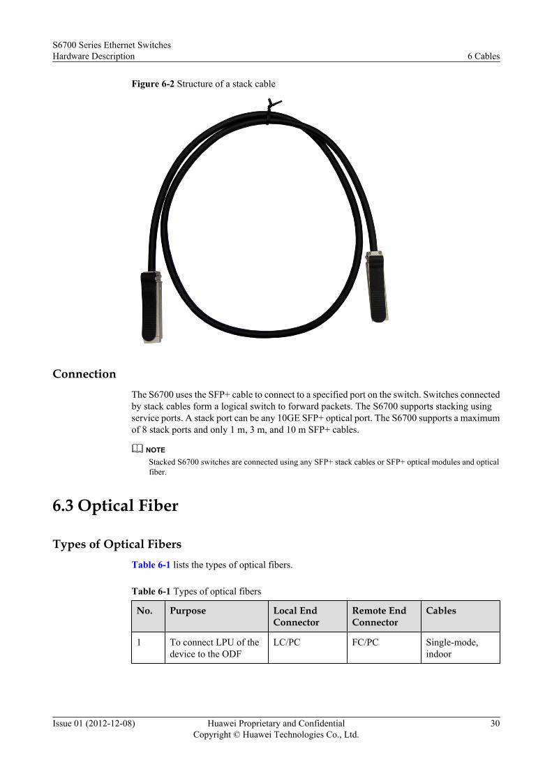
Figure 6-2 Structure of a stack cable
ConnectionThe S6700 uses the SFP+ cable to connect to a specified port on the switch. Switches connectedby stack cables form a logical switch to forward packets. The S6700 supports stacking usingservice ports. A stack port can be any 10GE SFP+ optical port. The S6700 supports a maximumof 8 stack ports and only 1 m, 3 m, and 10 m SFP+ cables.
NOTEStacked S6700 switches are connected using any SFP+ stack cables or SFP+ optical modules and opticalfiber.
6.3 Optical Fiber
Types of Optical FibersTable 6-1 lists the types of optical fibers.
Table 6-1 Types of optical fibers
No. Purpose Local EndConnector
Remote EndConnector
Cables
1 To connect LPU of thedevice to the ODF
LC/PC FC/PC Single-mode,indoor
S6700 Series Ethernet SwitchesHardware Description 6 Cables
Issue 01 (2012-12-08) Huawei Proprietary and ConfidentialCopyright © Huawei Technologies Co., Ltd.
30

No. Purpose Local EndConnector
Remote EndConnector
Cables
2 To connect LPUs of twodevices
LC/PC LC/PC Single-mode/multi-mode,indoor
3 To connect LPU of thedevice to another device
LC/PC SC/PC or LC/PC
Single-mode/multi-mode,indoor
Appearance and StructureA single-mode optical fiber and a multi-mode optical fiber have the same appearance butdifferent colors. A single-mode optical fiber is yellow and a multi-mode optical fiber is orangeblue.
Figure 6-3 shows the appearance of a single fiber.
Figure 6-3 Appearance of a single-mode optical fiber with LC/PC connectors
Figure 6-4 shows the appearance of a multi-mode fiber.
S6700 Series Ethernet SwitchesHardware Description 6 Cables
Issue 01 (2012-12-08) Huawei Proprietary and ConfidentialCopyright © Huawei Technologies Co., Ltd.
31
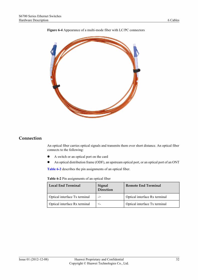
Figure 6-4 Appearance of a multi-mode fiber with LC/PC connectors
ConnectionAn optical fiber carries optical signals and transmits them over short distance. An optical fiberconnects to the following:
l A switch or an optical port on the cardl An optical distribution frame (ODF), an upstream optical port, or an optical port of an ONT
Table 6-2 describes the pin assignments of an optical fiber.
Table 6-2 Pin assignments of an optical fiber
Local End Terminal SignalDirection
Remote End Terminal
Optical interface Tx terminal -> Optical interface Rx terminal
Optical interface Rx terminal <- Optical interface Tx terminal
S6700 Series Ethernet SwitchesHardware Description 6 Cables
Issue 01 (2012-12-08) Huawei Proprietary and ConfidentialCopyright © Huawei Technologies Co., Ltd.
32

CAUTIONWhen connecting or removing the LC/PC optical connector, align the connector with the opticalport, and do not rotate the fiber. Pay attention to the following points:l Align the head of the fiber jumper with the optical port and insert the optical fiber into the
port gently.l To remove the fiber, press the latch on the connector and pull the fiber out.
Optical Fiber Selection CriteriaTable 6-3 lists the criteria for selecting optical fibers. Table 6-4 lists common optical connectors.
Table 6-3 Criteria for selecting optical fibers
Item Criteria
Length Survey result
Single-mode ormulti-mode
Optical transceiver type:l The multi-mode optical transmitting module is connected to the
multi-mode fiber.l The single-mode optical transmitting module is connected to the
single-mode fiber.NOTE
If the optical fiber jumper is used, the connector connected to the device must bethe LC/PC connector, and the connector connected to the remote end must be ofthe same type as the remote end port.
Optical connectortype
l Square connector: SC/PC, LC/PC and MTRJ/PCl Round connector: ST/PC and FC/PC
Table 6-4 Common optical connectors
SC/PC connectorLC/PC connector
FC/PC connector MTRJ/PC connector
S6700 Series Ethernet SwitchesHardware Description 6 Cables
Issue 01 (2012-12-08) Huawei Proprietary and ConfidentialCopyright © Huawei Technologies Co., Ltd.
33

ST/PC connector
-
6.4 Network Cable
Types of Network Cables
A network cable connects a maintenance terminal to the console port on the main control boardfor local or remote maintenance.
Network cables are classified into straight-through cables and crossover cables.
l A straight-through cable connects a terminal, such as a computer or switch, to the network.The straight-through cable uses two RJ45 connectors, which have the same pinout.
l A crossover cable connects two terminals, such as computers or switches. The crossovercable uses two RJ45 connectors, which have different pinouts.
Appearance and StructureNOTE
l Generally, a network cable is a standard unshielded network cable that uses RJ45 connectors.
l The appearances of the straight-through cable and the crossover cable are the same.
Figure 6-5 shows the appearance of a network cable.
Figure 6-5 Appearance of a network cable
S6700 Series Ethernet SwitchesHardware Description 6 Cables
Issue 01 (2012-12-08) Huawei Proprietary and ConfidentialCopyright © Huawei Technologies Co., Ltd.
34

Figure 6-6 shows the structure of a network cable.
Figure 6-6 Structure of a network cable
81
Pin AssignmentsTable 6-5 shows the pin assignments of a straight-through cable.
Table 6-5 Pin assignments of a straight-through cable
X1 Pin Wire Color X2 Pin
1 White and orange 1
2 Orange 2
3 White and green 3
4 Blue 4
5 White and blue 5
6 Green 6
7 White and brown 7
8 Brown 8
Table 6-6 shows the pin assignments of a crossover cable.
S6700 Series Ethernet SwitchesHardware Description 6 Cables
Issue 01 (2012-12-08) Huawei Proprietary and ConfidentialCopyright © Huawei Technologies Co., Ltd.
35

Table 6-6 Pin assignments of a crossover cable
X1 Pin Wire Color X2 Pin
1 White and orange 3
2 Orange 6
3 White and green 1
4 Blue 4
5 White and blue 5
6 Green 2
7 White and brown 7
8 Brown 8
NOTE
To achieve the best electrical transmission performance, ensure that the wires connected to pins 1 and 2 and topins 3 and 6 are twisted pairs.
6.5 DC Power Cable
Types of DC Power CablesDC power cables include a -48 V power return cable and a -48 V power cable. The -48 V powerreturn cable connects to terminal marked with RTN (+), and the -48 V power cable connects tothe terminal marked with NEG (–).
Appearance and StructureFigure 6-7 and Figure 6-8 show the appearance and structure of the 48 V power return cableand -48 V power cable.
S6700 Series Ethernet SwitchesHardware Description 6 Cables
Issue 01 (2012-12-08) Huawei Proprietary and ConfidentialCopyright © Huawei Technologies Co., Ltd.
36

Figure 6-7 Appearance of a -48 V power return cable
Figure 6-8 Appearance of a -48 V power cable
NOTEA -48 V power return cable is black and is connected to the RTN(+) terminal of the DC power supply. A-48 V power cable is blue and is connected to the NEG(-) terminal of the DC power supply.
S6700 Series Ethernet SwitchesHardware Description 6 Cables
Issue 01 (2012-12-08) Huawei Proprietary and ConfidentialCopyright © Huawei Technologies Co., Ltd.
37

ConnectionA DC power cable connects to the following:
l A DC power input port on the devicel Output power port on an external power system
6.6 AC Power Cable
Appearance and StructureFigure 6-9 shows the appearance of an AC power cable.
Figure 6-9 AC power cable
NOTEThe AC power cables used in different countries and regions may have different specifications. Figure6-9 shows the international standard AC power cable.
ConnectionAn AC power cable connects to the following:
l An AC power input port on the devicel Mains supply
6.7 Console Cable
Appearance and StructureFigure 6-11 and Figure 6-11 show the appearance and structure of a console cable.
S6700 Series Ethernet SwitchesHardware Description 6 Cables
Issue 01 (2012-12-08) Huawei Proprietary and ConfidentialCopyright © Huawei Technologies Co., Ltd.
38

Figure 6-10 Appearance of a console cable
Figure 6-11 Structure of a console cable
X1Pos.1
Pos.9
Pos.6
Pos.5
X2 1 8
Network port connector(8-pin, RJ-45)
D-type connector(9-pin, male)
Label
Pin Assignments
Table 6-7 describes the pin assignments of a console cable.
Table 6-7 Pin assignments of a console cable
Connector X2 (RJ45) Direction X1 (DB9) Signal
Pinassignment
1 ---> 8 Clear to Send (CTS)
2 ---> 6 Data Set Ready (DSR)
3 ---> 2 Receive Data (RXD)
4 - 5 GND
S6700 Series Ethernet SwitchesHardware Description 6 Cables
Issue 01 (2012-12-08) Huawei Proprietary and ConfidentialCopyright © Huawei Technologies Co., Ltd.
39

Connector X2 (RJ45) Direction X1 (DB9) Signal
5 - 5 GND
6 <--- 3 Transmit Data (TXD)
7 <--- 4 Data Terminal Ready (DTR)
8 <--- 7 Request to Send (RTS)
ConnectionA console cable connects the console port of the device to the serial port of an operation terminalto transmit configuration data. A shielded cable or an unshielded cable can be used accordingto the onsite situation.
A console cable connects the device and terminal as follows:
l The 8-pin RJ45 connector is inserted into the console port of the device.l The DB9 connector is inserted into the terminal serial port.
S6700 Series Ethernet SwitchesHardware Description 6 Cables
Issue 01 (2012-12-08) Huawei Proprietary and ConfidentialCopyright © Huawei Technologies Co., Ltd.
40

7 Optical Module
About This Chapter
NOTE
l In this document, optical modules are classified based on encapsulation types, and optical modules ofeach encapsulation type are classified based on interface rates.
l Appearances of optical modules in this document are only for reference, and appearances of actuallydelivered optical modules may differ.
7.1 Basic Concepts
7.2 SFP/eSFP Modules
7.3 SFP+ Modules
7.4 Huawei Certification
S6700 Series Ethernet SwitchesHardware Description 7 Optical Module
Issue 01 (2012-12-08) Huawei Proprietary and ConfidentialCopyright © Huawei Technologies Co., Ltd.
41

7.1 Basic Concepts
Appearance and StructureFigure 7-1 shows the appearance of an optical module.
Figure 7-1 Appearance of an optical module
1 3 24
5
8
7
6
1. Handle 2. Receiver 3. Transmitter4. Shell 5. Label 6. Dust cap7. Spring 8. Module connector
S6700 Series Ethernet SwitchesHardware Description 7 Optical Module
Issue 01 (2012-12-08) Huawei Proprietary and ConfidentialCopyright © Huawei Technologies Co., Ltd.
42

Terms
Encapsulation type Encapsulation type of an optical module. Encapsulation types of optical modules includeeSFP, SFP+, as described in Table 7-1.
Table 7-1 Encapsulation types of optical modules
EncapsulationType
Description Optical Module
eSFP Enhanced small form-factorpluggable. An eSFP module is anSFP module that supportsmonitoring of voltage, temperature,bias current, transmit opticalpower, and receive optical power.Sometimes, eSFP is called SFP.
GE optical module(including the single-fiberbidirectional optical module)
GE CWDM optical module
GE copper module
SFP+ Small form-factor pluggable plus,SFP with a higher rate. SFP+modules are more sensitive toelectromagnetic interference (EMI)because they have a higher rate. Toreduce EMI, SFP+ modules havemore springs than SFP modules andthe cages for SFP+ modules on acard are tighter.
10GE optical module
Transmission distance Maximum distance over which optical signals can transmit. Optical signals sent fromdifferent types of sources can transmit over different distances due to negative effects ofoptical fibers, such as dispersion and attenuation.
Interface rate Maximum rate of electrical signals that an optical device can transmit without bit errors.The interface rates defined in Ethernet standards include 125 Mbit/s, 1.25 Gbit/s, 10.3125Gbit/s, and 41.25 Gbit/s.
Center wavelength Wavelength measured at the midpoint of the half-amplitude line in the transmit spectrum.
Fiber mode Mode of fibers defining based on core diameters and features of optical fibers. Opticalfibers are classified into single-mode fibers and multimode fibers. Generally, multimodefibers have large core diameters and severe dispersion, so they transmit optical signalsover short distances when working with multimode optical modules. Single-mode fibershave small dispersion and can transmit optical signals over long distances when workingwith single-mode optical modules.
Pattern bandwidth Bandwidth measured at a point with transmit power several dB lower than that of thepoint with the peak center wavelength. Pattern bandwidth reflects spectrumcharacteristics of an optical module.
S6700 Series Ethernet SwitchesHardware Description 7 Optical Module
Issue 01 (2012-12-08) Huawei Proprietary and ConfidentialCopyright © Huawei Technologies Co., Ltd.
43

Fiber diameter Diameter of the core of a fiber. According to international standards for optical fibers,the diameter of a multimode fiber is 62.5 um or 50 um, and the diameter of a single-mode fiber is 9 um.
Fiber class Optical signals with different wavelengths have their best working windows in differentoptical fibers. To help efficiently adjust wavelengths or dispersion features of opticalfibers and change their refractive indexes, the following classes are defined: multimodefiber (G.651), common single-mode fiber (G.652), shifted dispersion fiber (G.653), andnon-zero shifted dispersion fiber (G.655). G.651 and G.652 are commonly used fiberclasses.
Connector type Type of the interface on an optical module to accommodate a fiber. Commonly usedconnector types are LC (applicable to all the SFP, SFP+, and XFP modules), SC, andMPO (applicable to 150 m QSFP+ and CXP modules).
Transmit optical power Output optical power of an optical module when it is working properly.
Maximum receiversensitivity
Minimum average input optical power that the receiver of an optical module can receivewithin a range of bit error rate (BER = 10 to 12).
Overload optical power Maximum average input optical power that the receiver of an optical module can receivewithin a range of bit error rate (BER = 10 to 12).
Extinction ratio Minimum ratio of the average optical power with signals transmitted against the averageoptical power without signals transmitted in complete modulation mode. The extinctionratio indicates the capability of an optical module to identify signal 0 and signal 1.
7.2 SFP/eSFP Modules
AppearanceFigure 7-2 shows the appearance of an SFP/eSFP optical module.
S6700 Series Ethernet SwitchesHardware Description 7 Optical Module
Issue 01 (2012-12-08) Huawei Proprietary and ConfidentialCopyright © Huawei Technologies Co., Ltd.
44

Figure 7-2 Appearance of an SFP/eSFP optical module
GE Optical Module
Table 7-2 and Table 7-3 list the attributes of a GE optical module.
Table 7-2 Attributes of GE optical modules
Model TransmissionDistance (km)
Standard
Fiber Type Supported Switch
eSFP-GE-SX-MM850
≤ 0.5 1000base-SX
l Fiber mode:multimode
l Patternbandwidth: 400MHz*km
l Core diameter:50 μm
l Connector type:LC
l S6700-24-EIl S6700-48-EI
SFP-GE-LX-SM1310
≤ 10 1000base-LX/LH
l Fiber mode:single-mode
l Connector type:LC
S6700 Series Ethernet SwitchesHardware Description 7 Optical Module
Issue 01 (2012-12-08) Huawei Proprietary and ConfidentialCopyright © Huawei Technologies Co., Ltd.
45

Model TransmissionDistance (km)
Standard
Fiber Type Supported Switch
S-SFP-GE-LH40-SM1310
≤ 40 1000base-LX/LH
S-SFP-GE-LH40-SM1550
1000base-LX/LH
S-SFP-GE-LH80-SM1550
≤ 80 1000base-ZX
eSFP-GE-ZX100-SM1550
≤ 100 1000base-ZX
SFP-GE-LX-SM1310-BIDI(Single-fiberbidirectionalopticalmodule)
≤ 10 1000base-BX
SFP-GE-LX-SM1490-BIDI(Single-fiberbidirectionalopticalmodule)
1000base-BX
S6700 Series Ethernet SwitchesHardware Description 7 Optical Module
Issue 01 (2012-12-08) Huawei Proprietary and ConfidentialCopyright © Huawei Technologies Co., Ltd.
46

Table 7-3 Optical parameters of GE optical modules
Model CenterWavelength (nm)
TransmitPower(dBm)
ReceiverSensitivity(dBm)
Overload OpticalPower(dBm)
ExtinctionRatio(dB)
OperatingTemperature
eSFP-GE-SX-MM850
850 -9.5 to-2.5
≤ -17.0 0 9 0°C to70°C
SFP-GE-LX-SM1310
1310 -9.0 to-3.0
≤ -20.0 -3.0 9
S-SFP-GE-LH40-SM1310
1310 -5.0 to0
≤ -23 -3.0 6
S-SFP-GE-LH40-SM1550
1550 -5.0 to0
≤ -22 -3.0 8.5
S-SFP-GE-LH80-SM1550
1550 -2.0 to5.0
≤ -23.0 -3.0 9
eSFP-GE-ZX100-SM1550
1550 0 to 5 ≤ -30.0 -9.0 8
SFP-GE-LX-SM1310-BIDI(Single-fiberbidirectional opticalmodule)
RX1490/TX1310
-9.0 to-3.0
≤ -19.5 -3.0 6
SFP-GE-LX-SM1490-BIDI(Single-fiberbidirectional opticalmodule)
RX1310/TX1490
-9.0 to-3.0
≤ -19.5 -3.0 6
GE-CWDM Optical ModuleTable 7-4 lists the attributes of a GE coarse wavelength division multiplexing (CWDM) opticalmodule.
S6700 Series Ethernet SwitchesHardware Description 7 Optical Module
Issue 01 (2012-12-08) Huawei Proprietary and ConfidentialCopyright © Huawei Technologies Co., Ltd.
47

Table 7-4 Attributes of CWDM optical modules
CenterWavelength (nm),Model
1471, eSFP-LH80-SM1471
1491, eSFP-LH80-SM1491
1511, eSFP-LH80-SM1511
1531, eSFP-LH80-SM1531
1551, eSFP-LH80-SM1551
1571, eSFP-LH80-SM1571
1591, eSFP-LH80-SM1591
1611, eSFP-LH80-SM1611
Specifications
Encapsulation type: eSFP
Transmission distance: ≤ 80 km
Fiber type: single-mode, LC
Standard: CWDM
Operating temperature: 0°C to 70°C
l Transmit power: 0 dBm to 5.0 dBml Receiver sensitivity: ≤ -28.0 dBml Overload optical power: -9.0 dBml Extinction ratio: 8.5 dB
Supported Switch
l S6700-24-EIl S6700-48-EI
NOTE
The appearance of CWDM optical modules is similar to that of common optical modules. These opticalmodules are distinguished by their labels. In practice, the corresponding optical fibers are labeled todistinguish the optical modules.
GE SFP Copper Module
Table 7-5 lists the attributes of a GE SFP copper module.
Table 7-5 Attributes of a GE SFP copper module
Model TransmissionDistance (km)
ConnectorType
Standard
OperatingTemperature
Supported Switch
SFP-1000BaseT
0.1 RJ45 1000Base-T
-40°C to+85°C
l S6700-24-EIl S6700-48-EI
7.3 SFP+ Modules
S6700 Series Ethernet SwitchesHardware Description 7 Optical Module
Issue 01 (2012-12-08) Huawei Proprietary and ConfidentialCopyright © Huawei Technologies Co., Ltd.
48

AppearanceFigure 7-3 shows the appearance of an SFP+ optical module.
Figure 7-3 Appearance of an SFP+ optical module
10GE SFP+ Optical ModuleTable 7-6 and Table 7-7 list the attributes of a 10GE SFP+ optical module.
S6700 Series Ethernet SwitchesHardware Description 7 Optical Module
Issue 01 (2012-12-08) Huawei Proprietary and ConfidentialCopyright © Huawei Technologies Co., Ltd.
49

Table 7-6 Attributes of 10GE SFP+ optical modules
Model TransmissionDistance (km)
Standard
Fiber Type Supported Switch
OSXD22N00
≤ 0.22 10Gbase-LRM
l Fiber mode: multimodel Pattern bandwidth: 500
MHz*kml Core diameter: 62.5 μm
or 50 μml Fiber class: OM1, OM2,
OM3l Connector type: LC
l S6700-24-EIl S6700-48-EI
OMXD30000
≤ 0.3 10Gbase-SR
l Fiber mode: multimodel Pattern bandwidth: 2000
MHz*kml Core diameter: 50 μml Connector type: LC
OSX010000
≤ 10 10Gbase-LR
l Fiber mode: single-model Connector type: LC
OSX040N01
≤ 40 10Gbase-ER
Table 7-7 Optical parameters of 10GE SFP+ optical modules
Model CenterWavelength (nm)
TransmitPower(dBm)
ReceiverSensitivity(dBm)
OverloadOpticalPower(dBm)
ExtinctionRatio(dB)
OperatingTemperature
OSXD22N00 1310
-6.5 to0.5
≤ -6.5 1.5 3.5 0°C to70°C
OMXD30000
850 -7.3 to-1.0
≤ -11.1 -1.0 3.0
OSX010000
1310 -8.2 to0.5
≤ -12.6 0.5 3.5
OSX040N01
1310 -4.7 to4.0
≤ -14.1 -1.0 3
S6700 Series Ethernet SwitchesHardware Description 7 Optical Module
Issue 01 (2012-12-08) Huawei Proprietary and ConfidentialCopyright © Huawei Technologies Co., Ltd.
50

7.4 Huawei Certification
Use Huawei certified optical modules. Non-Huawei-certified optical modules cannot ensuretransmission reliability and may affect service stability on the switch. Huawei is not responsiblefor any problem caused by non-Huawei-certified optical modules and will not fix such problems.
Huawei certification is a measure to ensure reliability and quality of optical modules. You canuse the display transceiver command to check whether an optical module has passed Huaweicertification.
If the Vendor Name field in the display transceiver command output displays HUAWEI, theoptical module has passed Huawei certification. If other values are displayed in this field, theoptical module is not a Huawei certified optical module.
<HUAWEI>display transceiver interface gigabitethernet 0/0/1gigabitethernet0/0/1 transceiver information: ------------------------------------------------------------- Common information: Transceiver Type :1000_BASE_SX_SFP Connector Type :LC Wavelength(nm) :850 Transfer Distance(m) :0(9um),300(50um),150(62.5um) Digital Diagnostic Monitoring :YES Vendor Name :HUAWEI Vendor Part Number :HFBR-5710L Ordering Name : ------------------------------------------------------------- Manufacture information: Manu. Serial Number :79K056C05802 Manufacturing Date :2007-09-14 Vendor Name :HUAWEI -------------------------------------------------------------
S6700 Series Ethernet SwitchesHardware Description 7 Optical Module
Issue 01 (2012-12-08) Huawei Proprietary and ConfidentialCopyright © Huawei Technologies Co., Ltd.
51