Embed Size (px)
Citation preview

Gas and Air Sensors
Product Specification
SenseAir ® S8-4B Miniature CO2 sensor safety switch
Driesen + Kern GmbH
Driesen+Kern GmbHAm Hasselt 25D-24576 Bad Bramstedt
Tel. +49 (0) 4192 8170-0www.driesen-kern.de Fax +49 (0) 4192 8170-99www.driesen-kern.com [email protected]
CONFIDENTIAL
Document PSP 111
Rev 7
Page 2 (12)
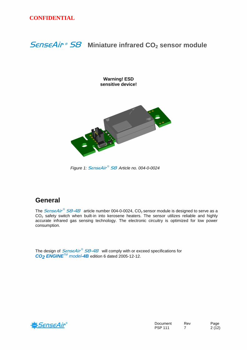
SenseAir ® S8 Miniature infrared CO2 sensor module
General
The SenseAir ® S8-4B article number 004-0-0024, CO2 sensor module is designed to serve as a
CO2 safety switch when built-in into kerosene heaters. The sensor utilizes reliable and highly accurate infrared gas sensing technology. The electronic circuitry is optimized for low power consumption.
The design of SenseAir ® S8-4B will comply with or exceed specifications for CO2 ENGINETM model-4B edition 6 dated 2005-12-12.
Warning! ESD sensitive device!
Figure 1: SenseAir ® S8 Article no. 004-0-0024

CONFIDENTIAL
Document PSP 111
Rev 7
Page 3 (12)
SenseAir ® S8-4B functional description During normal operation, the sensor measures ambient gas CO2 concentration every 30 seconds and will set alarm output when CO2 level is higher than 8000 ppm. A diagnostic routine will set Fault Alarm if any malfunction is detected. An alarm filter protects the sensor from issuing false alarm caused by intermittent short disturbances. The alarm output is an open drain FET transistor switch which is in open state in normal operation and sinks the output pin to zero volts in alarm conditions. If any of the three alarm states CO2 High, Power Low or Fault occur the unit sets the alarm. The output will stay in alarm mode until CO2 level is below 6500ppm or other reason for alarm has been removed.
The unit will start operating at power supply voltages as low as 3.5V. First the micro-controller starts up in sleep mode for about 30 seconds, and then power supply voltage is checked and if it is higher than 4.5 V the CO2 measurement sequence is started. During the measurement of CO2, the power supply voltage is checked and must exceed 4.0 V. If power supply voltage drops below either of the thresholds the system will immediately set the output alarm and go to sleep mode for about 10 seconds. Then the system is actively discharged so that the alarm output, and the sensor itself, will reset as soon as the input voltage is totally gone. To assure an alarm reset, the power supply has to be disconnected for more than 40 seconds.
Output status
CO2 Level
Normally open
Alarm stateConducting toground 6500 8000 ppm

CONFIDENTIAL
Document PSP 111
Rev 7
Page 4 (12)
Item SenseAir ® S8-4B
Target gas CO2
Operating Principle Non-dispersive infrared (NDIR)
Measurement range 400 to 32000ppm (represented internally in digital format)
Measurement interval 30 seconds
Accuracy ±1000ppm at alarm points between 7000 and 9000 ppm (Note 1)
Pressure dependence + 1.6 % reading per kPa deviation from normal pressure
Gas diffusion response time 2 minutes by 90%
Operating temperature -5º to 60º C
Operating humidity range 0 to 95% RH non condensed
Storage temperature -40° to +70°C
Storage Environment 0-95% RH non condensed non corrosive gases, no contamination to kerosene
Dimensions (mm) 61 x 20 x 8.5 mm (max dimensions)
Weight < 10 grams
Power supply 4.5 to 7.0 VDC unprotected against surges and reverse connection
Power consumption 250 mA peak, 2 mA average
Life expectancy 5+ years in normal indoor / office environments
Compliance with
Tested according Emission: EN 61000-6-3:2007, EN 61000-6-4:2007 Immunity: EN 61000-6-1:2007 RoHS directive 2011/65/EU
Output Alarm, Open Drain
Open drain FET; 7V/ 800mA, protected by a zener diode, normally open,
10k pull-up resistor to power (+).
8000/6500 (Alarm/Release) Normal state is open.
Transistor conducting at (CO2 > 8000ppm) OR (Unloaded Power voltage < 4.5V) OR (Loaded Power voltage < 4.0V) OR (Sensor Failure detected by self-diagnostics)
Maintenance Forced calibration (assuming 400 ppm exposure).
Self-diagnostics Full self-diagnostics at power up and continuously running self-diagnostics at every measurement.
Table 1: Key technical specification for the SenseAir ® S8-4B
_______________________________________________________________________ Note 1: Accuracy is specified over operating temperature range. Specification is referenced to certified calibration mixtures.
Uncertainty of calibration gas mixtures (+-2% currently) is to be added to the specified accuracy for absolute measurements.

CONFIDENTIAL
Document PSP 111
Rev 7
Page 5 (12)
Absolute maximum ratings
Stress greater than those listed in Table III may cause permanent damage to the device. These ratings are stress ratings only. Operation of the device at any condition outside those indicated in the operational section of these specifications is not implied. Exposure to absolute maximum rating for extended periods may affect device reliability.
Parameter Minimum Maximum Units Notes
Ambient temperature under bias - 40 85 C
Voltage on G+ pin with respect to G0 pin - 0.3 12 V 1
Maximum voltage on Calibration restore switch(S1) and Forced output test(S2) inputs
- 0.3 3.8 V 1
Maximum voltage on Output Alarm - 0.3 G+ + 0.5 V 1,2
Table 2: Absolute maximum ratings specification for the SenseAir ® S8-4B __________________________________________________________________________________________ Note 1: Specified parameter relies on specification of subcontractor and is not tested by SenseAir Note 2: OUT1 (Output Alarm) pin is internally pulled up to G+. External pull up to higher voltage will provide resistive divider
powering sensor via high resistance.

CONFIDENTIAL
Document PSP 111
Rev 7
Page 6 (12)
Gas diffusion area
Figure 2: Gas diffusion area SenseAir ® S8-4B
Pin assignment
Figure 3: Pin assignment SenseAir ® S8-4B
Diffusion area
G+ G0
OUT1, Output Alarm
S1
S2

CONFIDENTIAL
Document PSP 111
Rev 7
Page 7 (12)
Terminals description
The table below specifies terminals and I/O options of the SenseAir ® S8-4B The SenseAir ® S8-4B is equipped with a 3-pin connector (G+, G0, Output Alarm). Part number of the connector is B3B-PH-SM4-TB, manufacturer JST (www.jst.com).
Pin Function
Pin description / Parameter description
Electrical specification
Power supply
G+ Power supply positive terminal. Unprotected against reverse connection!
G0 Power supply negative terminal.
Sensor’s reference (ground) terminal.
Unprotected against reverse connection!
Outputs
OUT1, Output Alarm Open Drain FET transistor switch output. Internal protection. Absolute max voltage range(Note 1) Internal pull up to G+ resistor Max sink current (Note 1)
G0 - 0.3V to G+ + 0.5V 10k 800mA
Jumpers
Calibration
restore switch
(S1)
Digital input forcing background calibration. Background calibration is activated when closed for minimum 30 seconds assuming 400 ppm CO2 sensor exposure. Calibration occurs every 30 seconds during switch grounding (Note 2) Absolute max voltage range(Note 1) Internal pull up resistor Input low level (Note 1) Input high level (Note 1)
No internal protection, Internal pull-up to 3.3V at processor reset (power up and power down) - 0.3V to 3.8V 120K - 0.3V to 0.75V 2.3V to 3.6V
Forced output test (S2)
Digital input forcing Output Alarm, for testing purpose. Absolute max voltage range(Note 1) Internal pull up resistor Input low level (Note 1) Input high level (Note 1)
No internal protection, Internal pull-up to 3.3V at processor reset (power up and power down) - 0.3V to 3.8V 120K - 0.3V to 0.75V 2.3V to 3.6V
Table 3: I/O notations, description and electrical specification
_______________________________________________________________________ Note 1: Specified parameter relies on specification of subcontractor and is not tested by SenseAir.
Note 2: Do not ground S1 input for a long time. FLASH resource will be exhausted in 3.5 months in case of permanent S1 grounding.

CONFIDENTIAL
Document PSP 111
Rev 7
Page 8 (12)
Mechanical properties Sensor PCB may be colour green or black. Optical bench assembly (OBA) may be colour silver or black. Please refer to mechanical drawing for detailed specification of dimensions and tolerances.
WARNING! Under no circumstances should any force be applied to the OBA, this may permanently harm the sensor and most definitely affect performance. Sensor should be handled holding PCB only. Never touch sensor with bare hands, make sure that operators use ESD gloves. Note! ESD sensitive device!
Figure 4: Mechanical properties SenseAir ® S8-4B Article No 004-0-0024
Installation and soldering
During installation and assembly of sensor to PCB it is essential that compatible materials are used and that soldering process is managed. Avoid introduction of stress to the sensor’s PCB or OBA. SenseAir recommends hand soldering only. NB! Transport, handling and assembly may affect calibration. If for some reason the sensor needs to be re-calibrated, please refer to paragraph Maintenance. Please, contact SenseAir for further information!
OBA
Warning! ESD
sensitive device!
Never apply force to OBA! Handle sensor by holding PCB only!
Never touch sensor with bare hands!
CONFIDENTIAL
Document PSP 111
Rev 7
Page 9 (12)
Maintenance
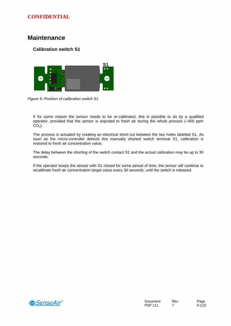
Calibration switch S1
Figure 5: Position of calibration switch S1
If for some reason the sensor needs to be re-calibrated, this is possible to do by a qualified operator, provided that the sensor is exposed to fresh air during the whole process (~400 ppm CO2).
The process is actuated by creating an electrical short-cut between the two holes labelled S1. As soon as the micro-controller detects this manually shorted switch terminal S1, calibration is restored to fresh air concentration value. The delay between the shorting of the switch contact S1 and the actual calibration may be up to 30 seconds. If the operator keeps the sensor with S1 closed for some period of time, the sensor will continue to recalibrate fresh air concentration target value every 30 seconds, until the switch is released.
S1

CONFIDENTIAL
Document PSP 111
Rev 7
Page 10 (12)
Alarm test mode
Figure 6: Position of forced output test switch S2
Forced output test switch S2 This function is intended for a qualified operator to check the sensor output and the subsequent system response by simulating sensor alarm. The process is trigged by putting a short across S2. When the micro-controller detects S2 is shorted the Alarm Output is set. The delay between shorting S2 and setting of alarm active may be up to 30 seconds. If S2 remains closed for some period of time, and if sensor is powered, the sensor will hold the output active until the switch closure is released. Delay of up to 30 seconds may occur between switch release and alarm output release.
S2
Figure 7: Timing diagram for switch S2

CONFIDENTIAL
Document PSP 111
Rev 7
Page 11 (12)
Active
measurement
G+
(Battery+)
V > 4.5 V
20 sec
1. High CO2 alarm time diagram. (Assume power good).
28 sec
0.4 to 1 sec
CO2 concentration
CO2 High Alarm Level
CO2 Alarm Reset Level
28 sec 28 sec 28 sec 28 sec 28 sec 28 sec 28 sec 28 sec 28 sec
Alarm
Signal
Output
Open transistor
1 2 3 4Alarm Filter 1
Closed transistor, conducting
Time
Time
Time
NOTE:
Simplified alarm filter operation for
steady growing CO2 reading is shown.
Active
measurement
G+
(Battery+)
4.5 V
20 sec
2. Power Low time diagram. (Assume CO2 concentration to be under alarm level).
28 sec
less than
0.1sec
28 sec 28 sec 28 sec 28 sec 28 sec
Alarm
Signal
Output
Open transistor
Closed transistor, conducting
Time
Time
Time
3.5V=< Vbattery <=4.5V
Current
consumption,
typical .
Not in scale.
4.0 V
Vbattery > 4.5 V
Open transistor
0.4 to 1 sec
50 uA
10 sec
45 mA
250 mA
Eventual voltage drop due to
too large internal resistance
of discharged battery
50 uA
10 sec
Sleep mode
50 uA
Remove
battery
Slow discharge of filter
capacitor in sleep mode
10 sec
~~3.3 VFast discharge of filter capacitor
Closed transistor, conducting
50 uA50 uA50 uA50 uA
Alarm output filter and time diagram

Gas and Air Sensors
SenseAir®
AB SenseAir®
North America SenseAir®
Chengdu Gas Sensors Ltd. Box 96 1603 S. Eastside Loop, Suite 207 First floor 8th of Xingke Road
Stationsgatan 12 Tucson, AZ 85710 Hi-Tech Industry Park
SE- 82060 Delsbo USA Jinniu district, Chengdu
Sweden Sichuan province
China
Phone: +46(0)653 – 71 77 70 Phone: +1 52.0.207.5032 Phone: +86-028 - 875 928 85
Fax: +46(0)653 – 71 77 89 Fax: +86-028 – 875 928 85
E-mail: [email protected] E-mail: [email protected] E-mail: [email protected]
Web page: www.senseair.com Web page: www.senseair.asia