Embed Size (px)
Citation preview

Maintenance Manual
Site Master™Model S810D and S820DBroadband Microwave Transmission Line and Antenna Analyzer
Anritsu Company490 Jarvis DriveMorgan Hill, CA 95037-2809USA
P/N: 10680-00003Revision: H
Printed: January 2014Copyright 2006 - 2014 Anritsu Company


CE Conformity MarkingAnritsu affixes the CE Conformity marking onto its conforming products in accordance with Council Directives of The Council Of The European Communities in order to indicate that these products conform to the EMC and LVD directive of the European Union (EU).
C-tick Conformity MarkingAnritsu affixes the C-tick marking onto its conforming products in accordance with the electromagnetic compliance regulations of Australia and New Zealand in order to indicate that these products conform to the EMC regulations of Australia and New Zealand.
Notes On Export ManagementThis product and its manuals may require an Export License or approval by the government of the product country of origin for re-export from your country.
Before you export this product or any of its manuals, please contact Anritsu Company to confirm whether or not these items are export-controlled.
When disposing of export-controlled items, the products and manuals need to be broken or shredded to such a degree that they cannot be unlawfully used for military purposes.
Mercury NotificationThis product uses an LCD backlight lamp that contains mercury. Disposal may be regulated due to environmental considerations. Please contact your local authorities or, within the United States, the Electronics Industries Alliance (www.eiae.org) for disposal or recycling information.
EPC WEEE Directive 2002/96/EC
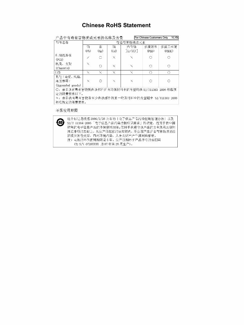
Chinese RoHS Statement

S810D/S820D MM 10680-00003 Rev. H Safety-1
Safety SymbolsTo prevent the risk of personal injury or loss related to equipment malfunction, Anritsu Company uses the following symbols to indicate safety-related information. For your own safety, please read the information carefully before operating the equipment.
Symbols Used in Manuals
Safety Symbols Used on Equipment and in ManualsThe following safety symbols are used inside or on the equipment near operation locations to provide information about safety items and operation precautions. Ensure that you clearly understand the meanings of the symbols and take the necessary precautions before operating the equipment. Some or all of the following five symbols may or may not be used on all Anritsu equipment. In addition, there may be other labels attached to products that are not shown in the diagrams in this manual.
Danger
This indicates a risk from a very dangerous condition or procedure that could result in serious injury or death and possible loss related to equipment malfunction. Follow all precautions and procedures to minimize this risk.
WarningThis indicates a risk from a hazardous condition or procedure that could result in light-to-severe injury or loss related to equipment malfunction. Follow all precautions and procedures to minimize this risk.
Caution
This indicates a risk from a hazardous procedure that could result in loss related to equipment malfunction. Follow all precautions and procedures to minimize this risk.
This indicates a prohibited operation. The prohibited operation is indicated symbolically in or near the barred circle.
This indicates a compulsory safety precaution. The required operation is indicated symbolically in or near the circle.
This indicates a warning or caution. The contents are indicated symbolically in or near the triangle.
This indicates a note. The contents are described in the box.
These indicate that the marked part should be recycled.

Safety-2 S810D/S820D MM 10680-00003 Rev. H
For Safety
Warning Always refer to the operation manual when working near locations at which the alert mark, shown on the left, is attached. If the operation, etc., is performed without heeding the advice in the operation manual, there is a risk of personal injury. In addition, the equipment performance may be reduced.
Moreover, this alert mark is sometimes used with other marks and descriptions indicating other dangers.
Warning
When supplying power to this equipment, connect the accessory 3-pin power cord to a 3-pin grounded power outlet. If a grounded 3-pin outlet is not available, use a conversion adapter and ground the green wire, or connect the frame ground on the rear panel of the equipment to ground. If power is supplied without grounding the equipment, there is a risk of receiving a severe or fatal electric shock.
WarningThis equipment can not be repaired by the operator. Do not attempt to remove the equipment covers or to disassemble internal components. Only qualified service technicians with a knowledge of electrical fire and shock hazards should service this equipment. There are high-voltage parts in this equipment presenting a risk of severe injury or fatal electric shock to untrained personnel. In addition, there is a risk of damage to precision components.
Caution
Electrostatic Discharge (ESD) can damage the highly sensitive circuits in the instrument. ESD is most likely to occur as test devices are being connected to, or disconnected from, the instrument’s front and rear panel ports and connectors. You can protect the instrument and test devices by wearing a static-discharge wristband. Alternatively, you can ground yourself to discharge any static charge by touching the outer chassis of the grounded instrument before touching the instrument’s front and rear panel ports and connectors. Avoid touching the test port center conductors unless you are properly grounded and have eliminated the possibility of static discharge.
Repair of damage that is found to be caused by electrostatic discharge is not covered under warranty.
WarningThis equipment is supplied with a rechargeable battery that could potentially leak hazardous compounds into the environment. These hazardous compounds present a risk of injury or loss due to exposure. Anritsu Company recommends removing the battery for long-term storage of the instrument and storing the battery in a leak-proof, plastic container. Follow the environmental storage requirements specified in the product data sheet.
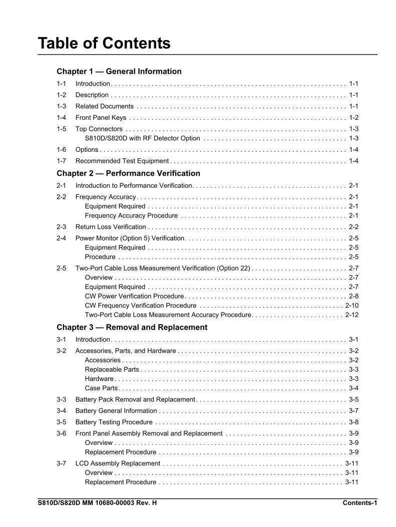
S810D/S820D MM 10680-00003 Rev. H Contents-1
Table of Contents
Chapter 1 — General Information
1-1 Introduction. . . . . . . . . . . . . . . . . . . . . . . . . . . . . . . . . . . . . . . . . . . . . . . . . . . . . . . . . . . . . . . . 1-1
1-2 Description . . . . . . . . . . . . . . . . . . . . . . . . . . . . . . . . . . . . . . . . . . . . . . . . . . . . . . . . . . . . . . . . 1-1
1-3 Related Documents . . . . . . . . . . . . . . . . . . . . . . . . . . . . . . . . . . . . . . . . . . . . . . . . . . . . . . . . . 1-1
1-4 Front Panel Keys . . . . . . . . . . . . . . . . . . . . . . . . . . . . . . . . . . . . . . . . . . . . . . . . . . . . . . . . . . . 1-2
1-5 Top Connectors . . . . . . . . . . . . . . . . . . . . . . . . . . . . . . . . . . . . . . . . . . . . . . . . . . . . . . . . . . . . 1-3
S810D/S820D with RF Detector Option . . . . . . . . . . . . . . . . . . . . . . . . . . . . . . . . . . . . . . . 1-3
1-6 Options . . . . . . . . . . . . . . . . . . . . . . . . . . . . . . . . . . . . . . . . . . . . . . . . . . . . . . . . . . . . . . . . . . . 1-4
1-7 Recommended Test Equipment . . . . . . . . . . . . . . . . . . . . . . . . . . . . . . . . . . . . . . . . . . . . . . . . 1-4
Chapter 2 — Performance Verification
2-1 Introduction to Performance Verification. . . . . . . . . . . . . . . . . . . . . . . . . . . . . . . . . . . . . . . . . . 2-1
2-2 Frequency Accuracy. . . . . . . . . . . . . . . . . . . . . . . . . . . . . . . . . . . . . . . . . . . . . . . . . . . . . . . . . 2-1
Equipment Required . . . . . . . . . . . . . . . . . . . . . . . . . . . . . . . . . . . . . . . . . . . . . . . . . . . . . . 2-1
Frequency Accuracy Procedure . . . . . . . . . . . . . . . . . . . . . . . . . . . . . . . . . . . . . . . . . . . . . 2-1
2-3 Return Loss Verification . . . . . . . . . . . . . . . . . . . . . . . . . . . . . . . . . . . . . . . . . . . . . . . . . . . . . . 2-2
2-4 Power Monitor (Option 5) Verification. . . . . . . . . . . . . . . . . . . . . . . . . . . . . . . . . . . . . . . . . . . . 2-5
Equipment Required . . . . . . . . . . . . . . . . . . . . . . . . . . . . . . . . . . . . . . . . . . . . . . . . . . . . . . 2-5
Procedure . . . . . . . . . . . . . . . . . . . . . . . . . . . . . . . . . . . . . . . . . . . . . . . . . . . . . . . . . . . . . . 2-5
2-5 Two-Port Cable Loss Measurement Verification (Option 22) . . . . . . . . . . . . . . . . . . . . . . . . . . 2-7
Overview . . . . . . . . . . . . . . . . . . . . . . . . . . . . . . . . . . . . . . . . . . . . . . . . . . . . . . . . . . . . . . . 2-7
Equipment Required . . . . . . . . . . . . . . . . . . . . . . . . . . . . . . . . . . . . . . . . . . . . . . . . . . . . . . 2-7
CW Power Verification Procedure . . . . . . . . . . . . . . . . . . . . . . . . . . . . . . . . . . . . . . . . . . . . 2-8
CW Frequency Verification Procedure . . . . . . . . . . . . . . . . . . . . . . . . . . . . . . . . . . . . . . . 2-10
Two-Port Cable Loss Measurement Accuracy Procedure. . . . . . . . . . . . . . . . . . . . . . . . . 2-12
Chapter 3 — Removal and Replacement
3-1 Introduction. . . . . . . . . . . . . . . . . . . . . . . . . . . . . . . . . . . . . . . . . . . . . . . . . . . . . . . . . . . . . . . . 3-1
3-2 Accessories, Parts, and Hardware . . . . . . . . . . . . . . . . . . . . . . . . . . . . . . . . . . . . . . . . . . . . . . 3-2
Accessories . . . . . . . . . . . . . . . . . . . . . . . . . . . . . . . . . . . . . . . . . . . . . . . . . . . . . . . . . . . . . 3-2
Replaceable Parts . . . . . . . . . . . . . . . . . . . . . . . . . . . . . . . . . . . . . . . . . . . . . . . . . . . . . . . . 3-3
Hardware . . . . . . . . . . . . . . . . . . . . . . . . . . . . . . . . . . . . . . . . . . . . . . . . . . . . . . . . . . . . . . . 3-3
Case Parts. . . . . . . . . . . . . . . . . . . . . . . . . . . . . . . . . . . . . . . . . . . . . . . . . . . . . . . . . . . . . . 3-4
3-3 Battery Pack Removal and Replacement . . . . . . . . . . . . . . . . . . . . . . . . . . . . . . . . . . . . . . . . . 3-5
3-4 Battery General Information . . . . . . . . . . . . . . . . . . . . . . . . . . . . . . . . . . . . . . . . . . . . . . . . . . . 3-7
3-5 Battery Testing Procedure . . . . . . . . . . . . . . . . . . . . . . . . . . . . . . . . . . . . . . . . . . . . . . . . . . . . 3-8
3-6 Front Panel Assembly Removal and Replacement . . . . . . . . . . . . . . . . . . . . . . . . . . . . . . . . . 3-9
Overview . . . . . . . . . . . . . . . . . . . . . . . . . . . . . . . . . . . . . . . . . . . . . . . . . . . . . . . . . . . . . . . 3-9
Replacement Procedure . . . . . . . . . . . . . . . . . . . . . . . . . . . . . . . . . . . . . . . . . . . . . . . . . . . 3-9
3-7 LCD Assembly Replacement . . . . . . . . . . . . . . . . . . . . . . . . . . . . . . . . . . . . . . . . . . . . . . . . . 3-11
Overview . . . . . . . . . . . . . . . . . . . . . . . . . . . . . . . . . . . . . . . . . . . . . . . . . . . . . . . . . . . . . . 3-11
Replacement Procedure . . . . . . . . . . . . . . . . . . . . . . . . . . . . . . . . . . . . . . . . . . . . . . . . . . 3-11
Contents-2 S810D/S820D MM 10680-00003 Rev. H
Table of Contents (Continued)
3-8 Keypad PCB Replacement . . . . . . . . . . . . . . . . . . . . . . . . . . . . . . . . . . . . . . . . . . . . . . . . . . . 3-12
Overview . . . . . . . . . . . . . . . . . . . . . . . . . . . . . . . . . . . . . . . . . . . . . . . . . . . . . . . . . . . . . . 3-12
Replacement Procedure . . . . . . . . . . . . . . . . . . . . . . . . . . . . . . . . . . . . . . . . . . . . . . . . . . 3-12
3-9 Keypad Membrane Replacement . . . . . . . . . . . . . . . . . . . . . . . . . . . . . . . . . . . . . . . . . . . . . . 3-13
Overview . . . . . . . . . . . . . . . . . . . . . . . . . . . . . . . . . . . . . . . . . . . . . . . . . . . . . . . . . . . . . . 3-13
Replacement Procedure . . . . . . . . . . . . . . . . . . . . . . . . . . . . . . . . . . . . . . . . . . . . . . . . . . 3-13
3-10 Power Monitor PCB Replacement . . . . . . . . . . . . . . . . . . . . . . . . . . . . . . . . . . . . . . . . . . . . . 3-14
Overview . . . . . . . . . . . . . . . . . . . . . . . . . . . . . . . . . . . . . . . . . . . . . . . . . . . . . . . . . . . . . . 3-14
Replacement Procedure . . . . . . . . . . . . . . . . . . . . . . . . . . . . . . . . . . . . . . . . . . . . . . . . . . 3-14
3-11 Real Time Clock Battery Replacement . . . . . . . . . . . . . . . . . . . . . . . . . . . . . . . . . . . . . . . . . . 3-15
Overview . . . . . . . . . . . . . . . . . . . . . . . . . . . . . . . . . . . . . . . . . . . . . . . . . . . . . . . . . . . . . . 3-15
Procedure . . . . . . . . . . . . . . . . . . . . . . . . . . . . . . . . . . . . . . . . . . . . . . . . . . . . . . . . . . . . . 3-15
3-12 Main/RF PCB Assembly Replacement . . . . . . . . . . . . . . . . . . . . . . . . . . . . . . . . . . . . . . . . . . 3-16
Overview . . . . . . . . . . . . . . . . . . . . . . . . . . . . . . . . . . . . . . . . . . . . . . . . . . . . . . . . . . . . . . 3-16
Replacement Procedure . . . . . . . . . . . . . . . . . . . . . . . . . . . . . . . . . . . . . . . . . . . . . . . . . . 3-16
3-13 Source Control PCB Assembly Replacement. . . . . . . . . . . . . . . . . . . . . . . . . . . . . . . . . . . . . 3-18
Overview . . . . . . . . . . . . . . . . . . . . . . . . . . . . . . . . . . . . . . . . . . . . . . . . . . . . . . . . . . . . . . 3-18
Replacement Procedure . . . . . . . . . . . . . . . . . . . . . . . . . . . . . . . . . . . . . . . . . . . . . . . . . . 3-18
Appendix A — Test Data Master for CW Source Modules
Index

S810D/S820D MM 10680-00003 Rev. H 1-1
Chapter 1 — General Information
1-1 IntroductionThis manual provides maintenance instructions for the Site Master Model S810D/S820D Broadband Microwave Transmission Line and Antenna Analyzer. It describes the product and provides performance verification procedures, parts replacement procedures, and a replaceable parts list.
1-2 DescriptionThe Site Master S810D, covering 25 MHz to 10.5, and the S820D, covering 25 MHz to 20.0 GHz, are the most accurate, reliable and convenient one port microwave transmission line and antenna analyzers available for installation, verification, troubleshooting, and repair of microwave communication systems.
Measurement capabilities includes return loss, SWR, cable loss, and distance-to-fault (DTF) analysis. Patented RF interference rejection enables accurate measurements in the presence of high RF activity. Data Analysis software enables assessment of system trends, problems, and performance in addition to professional report generation. An optional power monitor is available to make power measurements quickly and easily. A built-in GPS receiver (optional) provides location information for each trace and saved with archived data.
The Site Master Models S810D and S820D use vector error correction, solving the most common and the most difficult accuracy problems of field test equipment operation, while improving system quality and reducing maintenance expenses. Difficult test specifications are easy to verify with the Site Master Models S810D and S820D. Vector error correction and a simple, friendly user interface within the unit further improve the quality and convenience of measurements compared to traditional scalar techniques. Vector error correction also improves the quality of Distance-To-Fault data. Not only is the reflection magnitude more accurate, the waveguide dispersion correction for fault distance (different frequencies travel at different speeds) is also more accurate and repeatable.
1-3 Related DocumentsOther documents are available for the S810D and S820D at the Anritsu web site at www.anristu.com.
• Site Master S810D and S820D User Guide (10680-00001)
• Site Master S8x0D Programming Manual (10680-00002)
Front Panel Keys General Information
1-2 S810D/S820D MM 10680-00003 Rev. H
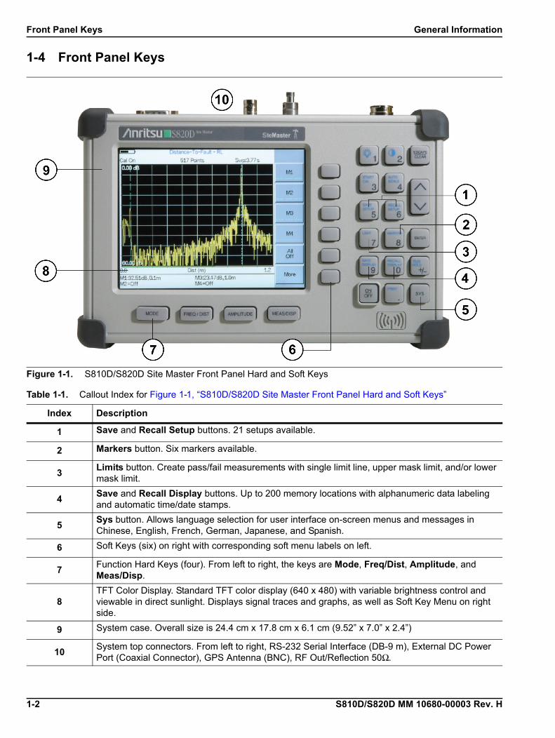
1-4 Front Panel Keys
Figure 1-1. S810D/S820D Site Master Front Panel Hard and Soft Keys
Table 1-1. Callout Index for Figure 1-1, “S810D/S820D Site Master Front Panel Hard and Soft Keys”
Index Description
1 Save and Recall Setup buttons. 21 setups available.
2 Markers button. Six markers available.
3Limits button. Create pass/fail measurements with single limit line, upper mask limit, and/or lower mask limit.
4Save and Recall Display buttons. Up to 200 memory locations with alphanumeric data labeling and automatic time/date stamps.
5Sys button. Allows language selection for user interface on-screen menus and messages in Chinese, English, French, German, Japanese, and Spanish.
6 Soft Keys (six) on right with corresponding soft menu labels on left.
7Function Hard Keys (four). From left to right, the keys are Mode, Freq/Dist, Amplitude, and Meas/Disp.
8TFT Color Display. Standard TFT color display (640 x 480) with variable brightness control and viewable in direct sunlight. Displays signal traces and graphs, as well as Soft Key Menu on right side.
9 System case. Overall size is 24.4 cm x 17.8 cm x 6.1 cm (9.52” x 7.0” x 2.4”)
10System top connectors. From left to right, RS-232 Serial Interface (DB-9 m), External DC Power Port (Coaxial Connector), GPS Antenna (BNC), RF Out/Reflection 50Ω.
General Information Top Connectors
S810D/S820D MM 10680-00003 Rev. H 1-3
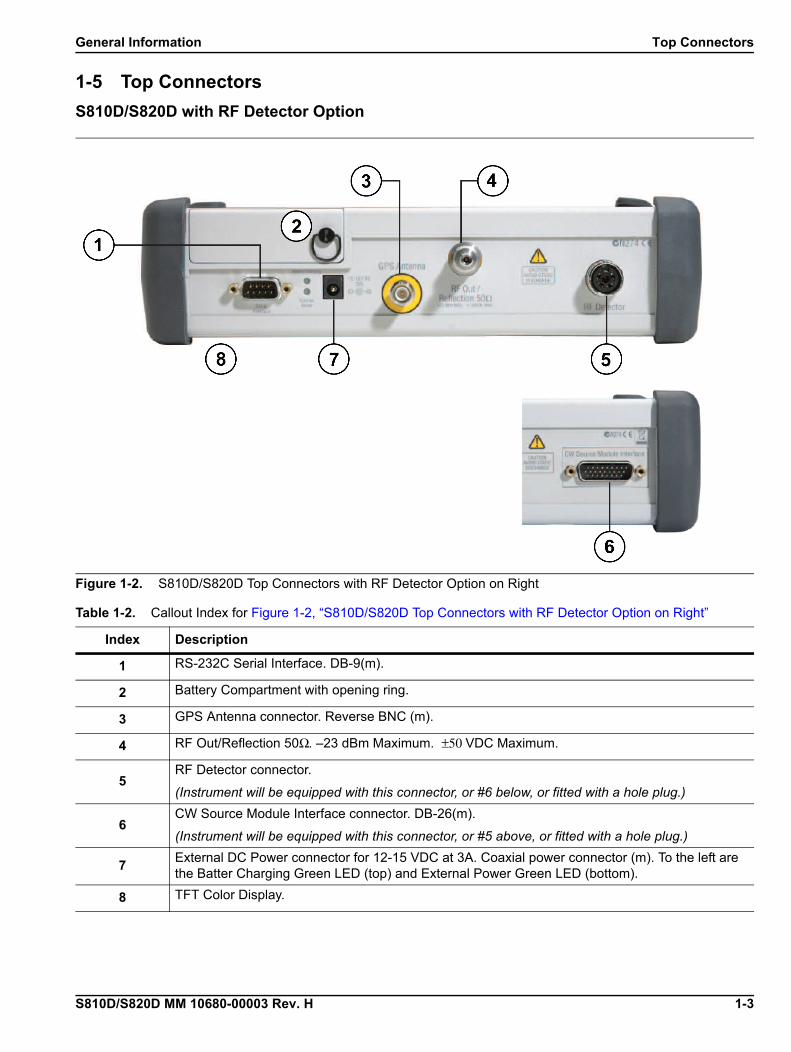
1-5 Top Connectors
S810D/S820D with RF Detector Option
Figure 1-2. S810D/S820D Top Connectors with RF Detector Option on Right
Table 1-2. Callout Index for Figure 1-2, “S810D/S820D Top Connectors with RF Detector Option on Right”
Index Description
1 RS-232C Serial Interface. DB-9(m).
2 Battery Compartment with opening ring.
3 GPS Antenna connector. Reverse BNC (m).
4 RF Out/Reflection 50Ω. –23 dBm Maximum. ±50 VDC Maximum.
5RF Detector connector.
(Instrument will be equipped with this connector, or #6 below, or fitted with a hole plug.)
6CW Source Module Interface connector. DB-26(m).
(Instrument will be equipped with this connector, or #5 above, or fitted with a hole plug.)
7External DC Power connector for 12-15 VDC at 3A. Coaxial power connector (m). To the left are the Batter Charging Green LED (top) and External Power Green LED (bottom).
8 TFT Color Display.

Options General Information
1-4 S810D/S820D MM 10680-00003 Rev. H
1-6 Options• Option 2, 2 MHz Frequency Extension (S8X0D/2)
• Option 5, Power Monitor (S8X0D/5 sensor not included)
• Option 11NF, Replaces Standard K (f) Test Port Connector with N(f) (S8X0D/11NF)
• Option 22NF, N(f) 2-Port Cable Loss Measurements (S8X0D/22NF)
• Option 22SF, SMA (f) 2-Port Cable Loss Measurements (S8X0D/22SF)
• Option 31, GPS Receiver (S8X0D/31)
1-7 Recommended Test EquipmentThe following test equipment is recommended for use in testing and maintaining the Site Master S810D and S820D.
Table 1-3. Recommended Text Equipment
Instrument Critical Specification Recommended Manufacturer/Model
Frequency Counter Frequency: < 3 GHz Anritsu Model MF2412B/C with Option 01. Without Option 01 requires a 10 MHz external reference
Calibration/Verification Kit Special, designed by Anritsu Anritsu Model SC6815, includes components with N and K type connectors.
Calibration/Verification Kit Special, designed by Anritsu Anritsu Model SC7668, includes components with N connectors. Use with instruments with Option 11NF.
RF Reference Source Frequency: 50 MHz
Power Output: 0 dBm
Anritsu Model MA2418A
DC Power Supply For Anritsu Model MA2418A Anritsu Part Number 2000-933
RF Detector Frequency: 10 MHz to 20 GHz Anritsu Model 560-7N50B
Adapter Connector: N(m) to K (f) Anritsu Model 34NKF50
Attenuator Attenuation: 10 dB
Connector: N(m) to N(f)
Aeroflex/Weinschel Model 1-10
Attenuator Attenuation: 30 dB
Connector: N(m) to N(f)
Aeroflex/Weinschel Model 1-30
RF Coaxial Cable Frequency: 10 MHz to 20 GHz
Connector: K (m) to K (m)
Any
RF Coaxial Cable Connector: BNC (m) to BNC (m) Any
Personal Computer Serial Port Any Windows XP PC
Serial Cable Null Modem Anritsu Part Number 800-441
Attenuator Attenuation: 10 dB
Connector: K (m) to K (f)
Anritsu Model 43KC-10
Attenuator Attenuation: 20 dB
Connector: K (m) to K (f)
Anritsu Model 43KC-20
Adapter Connector: N(f) to K (m) Anritsu Model 34NFK50
S810D/S820D MM 10680-00003 Rev. H 2-1
Chapter 2 — Performance Verification
2-1 Introduction to Performance VerificationThis chapter contains tests that can be used to verify the performance of the Site Master Models S810D and S820D.
• Section “2-2 Frequency Accuracy” on page 2-1
• Section “2-3 Return Loss Verification” on page 2-2
• Section “2-4 Power Monitor (Option 5) Verification” on page 2-5
• Section “2-5 Two-Port Cable Loss Measurement Verification (Option 22)” on page 2-7
• “CW Power Verification Procedure” on page 2-8• “CW Frequency Verification Procedure” on page 2-10
2-2 Frequency AccuracyThe following test can be used to verify the CW frequency accuracy of the Site Master. Measurement calibration of the Site Master is not required for this test.
Equipment Required• Anritsu Model MF2412B/C Frequency Counter or equivalent
• RF Cable with appropriate connectors to connect the instrument and the frequency counter
Frequency Accuracy Procedure
1. Connect the external power supply (Anritsu part number 40-187-R) to the Site Master.
2. Press and hold the ESCAPE/CLEAR key, then press the ON/OFF key to turn on the Site Master.• This sets the instrument to the factory preset state.
3. Press the FREQ/DIST key.
4. Press the F1 soft key, set to 2 GHz, then press the ENTER key.
5. Press the F2 soft key, set to 2 GHz, then press the ENTER key.
6. Press the MEAS/DISP key and then the Fixed CW soft key to turn Fixed CW on.
7. Connect the RF cable from the Site Master Test Port to the RF Input on the Frequency Counter.
8. Verify that the frequency readout on the Frequency Counter is 2 GHz ±6 kHz.
9. Press the Fixed CW soft key to turn Fixed CW off.
Note Before continuing, allow a five minute warm up for the internal circuitry to stabilize.
Return Loss Verification Performance Verification
2-2 S810D/S820D MM 10680-00003 Rev. H
2-3 Return Loss VerificationThe following test can be used to verify the accuracy of return loss measurements. Measurement calibration of the Site Master is required for this test. The Verification Software (P/N 2300-488) included with the Anritsu SC6815 Calibration/Verification Kit or the Anritsu SC7668 Calibration Kit must be installed into the PC prior to performing this test.
Equipment Required
• Anritsu SC6815 Calibration/Verification Kit.
• Anritsu SC7668 Calibration/Verification Kit.
• Personal Computer running Windows 95 or later, one available COM port, a CDROM drive and/or a USB port.
Return Loss Software Installation
1. Insert the Verification Software CD into the CDROM drive.
2. Click the Start button and select Run.
3. In the Run box, type x:\setup (where x is the drive letter of the CDROM drive) and select OK.
4. Follow the on screen setup instructions to install the Verification Software.
5. After the software has been installed, re-boot the PC.
Return Loss Verification Procedure
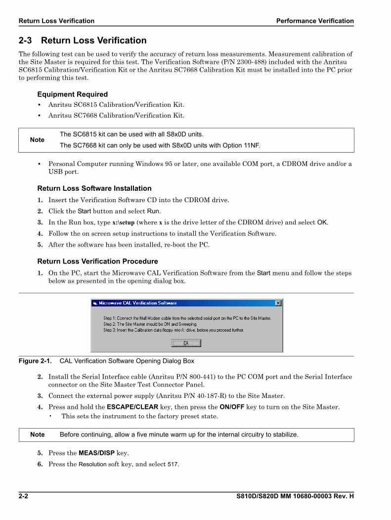
1. On the PC, start the Microwave CAL Verification Software from the Start menu and follow the steps below as presented in the opening dialog box.
2. Install the Serial Interface cable (Anritsu P/N 800-441) to the PC COM port and the Serial Interface connector on the Site Master Test Connector Panel.
3. Connect the external power supply (Anritsu P/N 40-187-R) to the Site Master.
4. Press and hold the ESCAPE/CLEAR key, then press the ON/OFF key to turn on the Site Master.• This sets the instrument to the factory preset state.
5. Press the MEAS/DISP key.
6. Press the Resolution soft key, and select 517.
NoteThe SC6815 kit can be used with all S8x0D units.
The SC7668 kit can only be used with S8x0D units with Option 11NF.
Figure 2-1. CAL Verification Software Opening Dialog Box
Note Before continuing, allow a five minute warm up for the internal circuitry to stabilize.
Performance Verification Return Loss Verification
S810D/S820D MM 10680-00003 Rev. H 2-3
7. Insert the Calibration USB memory device or disc that came with the SC6815 kit or the SC7668 kit into the PC disk drive.
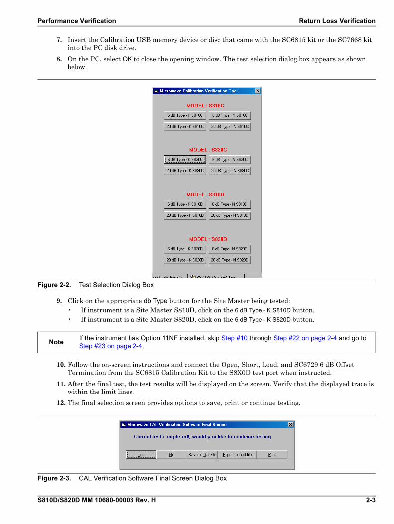
8. On the PC, select OK to close the opening window. The test selection dialog box appears as shown below.
9. Click on the appropriate db Type button for the Site Master being tested:• If instrument is a Site Master S810D, click on the 6 dB Type - K S810D button.• If instrument is a Site Master S820D, click on the 6 dB Type - K S820D button.
10. Follow the on-screen instructions and connect the Open, Short, Load, and SC6729 6 dB Offset Termination from the SC6815 Calibration Kit to the S8X0D test port when instructed.
11. After the final test, the test results will be displayed on the screen. Verify that the displayed trace is within the limit lines.
12. The final selection screen provides options to save, print or continue testing.
Figure 2-2. Test Selection Dialog Box
NoteIf the instrument has Option 11NF installed, skip Step #10 through Step #22 on page 2-4 and go to Step #23 on page 2-4,
Figure 2-3. CAL Verification Software Final Screen Dialog Box
Return Loss Verification Performance Verification
2-4 S810D/S820D MM 10680-00003 Rev. H
13. To save the data as a text file, select Export to Text File. The software will prompt for a name and location to save the file. The data will be saved in a tabular format that can be read by most text editor programs.
14. To save the data as a dat file, select Save as Dat File. The software will prompt for a name and location to save the file. A dat file saves the data in a graphical format that can be recalled and viewed using the Verification Software program.
15. To print the data, select Print. The software first prompts to save the data as a text file (see Step #13) and then prints the data to the default printer connected to the PC.
16. When the final selection screen reappears, click the Yes button to continue.
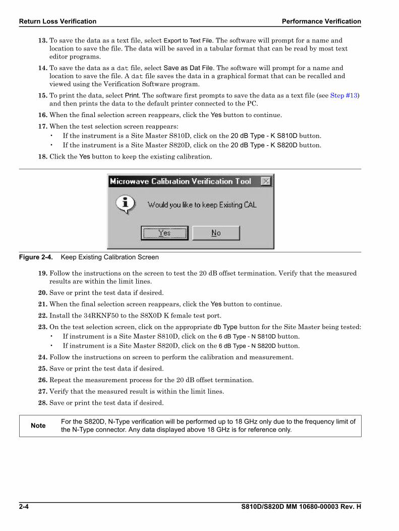
17. When the test selection screen reappears:• If the instrument is a Site Master S810D, click on the 20 dB Type - K S810D button.• If the instrument is a Site Master S820D, click on the 20 dB Type - K S820D button.
18. Click the Yes button to keep the existing calibration.
19. Follow the instructions on the screen to test the 20 dB offset termination. Verify that the measured results are within the limit lines.
20. Save or print the test data if desired.
21. When the final selection screen reappears, click the Yes button to continue.
22. Install the 34RKNF50 to the S8X0D K female test port.
23. On the test selection screen, click on the appropriate db Type button for the Site Master being tested:• If instrument is a Site Master S810D, click on the 6 dB Type - N S810D button.• If instrument is a Site Master S820D, click on the 6 dB Type - N S820D button.
24. Follow the instructions on screen to perform the calibration and measurement.
25. Save or print the test data if desired.
26. Repeat the measurement process for the 20 dB offset termination.
27. Verify that the measured result is within the limit lines.
28. Save or print the test data if desired.
Figure 2-4. Keep Existing Calibration Screen
NoteFor the S820D, N-Type verification will be performed up to 18 GHz only due to the frequency limit of the N-Type connector. Any data displayed above 18 GHz is for reference only.
Performance Verification Power Monitor (Option 5) Verification
S810D/S820D MM 10680-00003 Rev. H 2-5
2-4 Power Monitor (Option 5) VerificationIf the Power Monitor (Option 5) is installed in the Site Master, the following test can be used to verify the accuracy of the power measurements. Measurement calibration of the Site Master is not required for this test.
Equipment Required• RF Detector, 10 MHz to 20 GHz, Anritsu 560-7N50B
• 10 dB Attenuator, Aeroflex/Weinschel 1-10
• 30 dB Attenuator, Aeroflex/Weinschel 1-30
• 0 dBm 50 MHz RF Reference Source, Anritsu MA2418A• The 50 MHz Calibrator Output on a power meter can be used as a substitute for the RF
Reference Source.
• DC Power Supply for the MA2418A, Anritsu 2000-933
Procedure
1. Connect the DC power supply to the MA2418A Reference Source.• For Power Monitor Setup, see Figure 2-5, “Power Monitor Verification Setup” on page 2-6.
2. Connect the external power supply (Anritsu part number 40-187-R) to the Site Master.
3. Press and hold the ESCAPE/CLEAR key, then press the ON/OFF key to turn on the Site Master.• This sets the instrument to the factory preset state.
4. Press the MODE (9) key.
5. Use the Up/Down arrow key to highlight Power Monitor, then press ENTER.
6. Connect the RF Detector output to the RF Detector input of the Site Master.
7. With no power applied to the detector, press the Zero soft key to zero the power monitor. When complete, Zero Adj:On is displayed in the message area.
8. Connect the MA2418A Reference Source to the input of the 560-7N50B RF detector. Verify that the power monitor reading is 0.0 dBm ±1 dB.
9. Connect the output of the MA2418A Reference Source to the two attenuators so as to add 40 dB of attenuation (see Figure 2-5, “Power Monitor Verification Setup” on page 2-6).
10. Connect the MA2418A Reference Source and the attenuators to the input of the 560-7N50B RF detector.

Power Monitor (Option 5) Verification Performance Verification
2-6 S810D/S820D MM 10680-00003 Rev. H
11. Verify that the power monitor reading is now –40.0 dBm ±2 dB.
Figure 2-5. Power Monitor Verification Setup
Performance Verification Two-Port Cable Loss Measurement Verification (Option 22)
S810D/S820D MM 10680-00003 Rev. H 2-7
2-5 Two-Port Cable Loss Measurement Verification (Option 22)
Overview
The two-port cable loss measurement verification consists of three procedures:
• CW Power Verification Procedure with the CW Frequency Verification
• Two-Port Cable-Loss Measurement Accuracy Verification Procedure
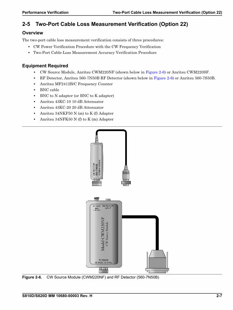
Equipment Required• CW Source Module, Anritsu CWM220NF (shown below in Figure 2-6) or Anritsu CWM220SF.
• RF Detector, Anritsu 560-7N50B RF Detector (shown below in Figure 2-6) or Anritsu 560-7S50B.
• Anritsu MF2412B/C Frequency Counter
• BNC cable
• BNC to N adapter (or BNC to K adapter)
• Anritsu 43KC-10 10 dB Attenuator
• Anritsu 43KC-20 20 dB Attenuator
• Anritsu 34NKF50 N (m) to K (f) Adapter
• Anritsu 34NFK50 N (f) to K (m) Adapter
Figure 2-6. CW Source Module (CWM220NF) and RF Detector (560-7N50B)

Two-Port Cable Loss Measurement Verification (Option 22) Performance Verification
2-8 S810D/S820D MM 10680-00003 Rev. H
CW Power Verification Procedure
1. Turn off the Site Master.
2. Connect the input port of the detector to the RF OUT X (f) of the CW Source Module.
3. Connect the cable of the detector to the DETECTOR INPUT of the CW Source Module.
4. Connect the TO S8X0D RF PORT X-TYPE of the CW Source Module to RF OUT of S8X0D.
5. Connect the cable of the CW Source Module to the CW Source Module Interface port of the S8X0D as shown in Figure 2-7 below.
NoteAlways turn off the S8X0D before connecting or disconnecting the CWM220xF CW Source Module to the CW Source Module Interface port of the S8X0D.
Figure 2-7. Two-Port Cable Loss General Connections
Table 2-1. Callout Index for Figure 2-7, “Two-Port Cable Loss General Connections”
Index Callout Description (1 of 2)
1 S810D/S820D SiteMaster
2 CW Source Module To S8X0D RF Port connected to the S8xD RF Out/Reflection 50Ω connector
3 Anritsu CW Source Module
4 CW Source Module RF OUT port connected the RF Detector Input Port
5 RF Detector
6 RF Detector Cable Input Plug connected to the CW Source Module Detector Input port

Performance Verification Two-Port Cable Loss Measurement Verification (Option 22)
S810D/S820D MM 10680-00003 Rev. H 2-9
6. Press and hold the ESCAPE/CLEAR key, then press the ON/OFF key to turn on the S8x0D.
7. Press MODE hard key.
8. Use the Up/Down arrow key to highlight Cable Loss – Two Port, then press ENTER.
9. Press the F1 soft key and set F1 = 10 MHz.
10. Press the F2 soft key and:• If the instrument is a Site Master S810D unit, set F2 = 10.5 GHz.• If the instrument is a Site Master S820D unit:
with CWM220NF and CWM220B-NF, set F2 = 18 GHzwith CWM220SF and CWM220B-SF, set F2 = 20 GHz.
11. Observe that the waveform displayed resembles the display shown in Figure 2-8 below.
12. Press the MARKER soft key and:• Select M1, select Marker to Peak.
• Select M2, select Marker to Valley.
13. Verify that:• M1 is less than +15 dBm.• M2 is greater than –15 dBm.
7CW Source Module CW Source Module Interface port connected to the S8x0D CW Source Module Interface
Figure 2-8. Cable Loss Two-Port Typical Waveform
Table 2-1. Callout Index for Figure 2-7, “Two-Port Cable Loss General Connections”
Index Callout Description (2 of 2)
Two-Port Cable Loss Measurement Verification (Option 22) Performance Verification
2-10 S810D/S820D MM 10680-00003 Rev. H
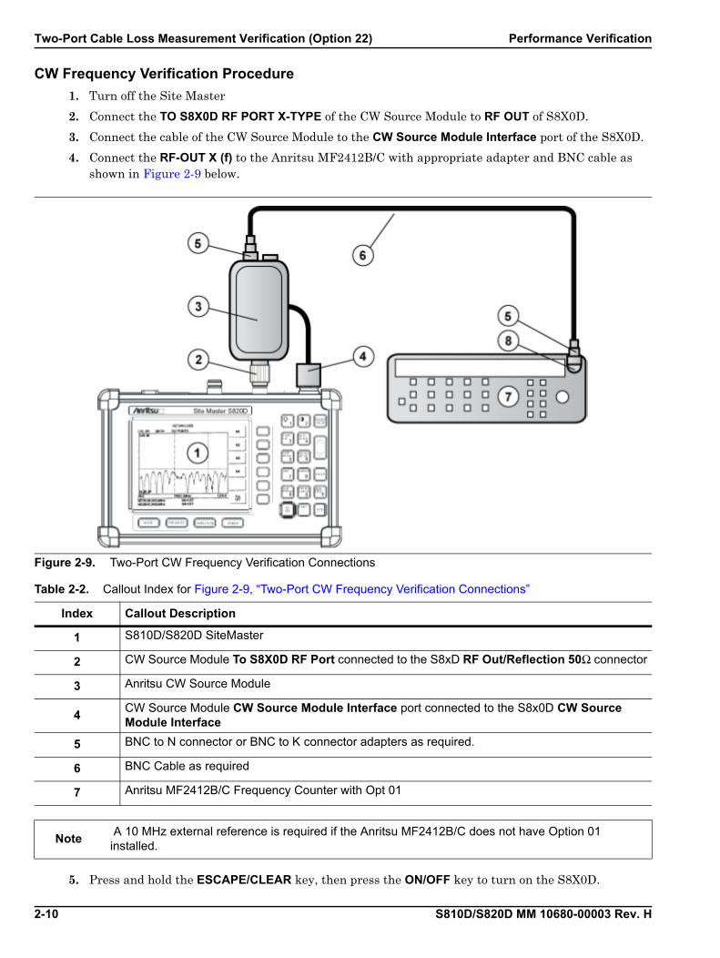
CW Frequency Verification Procedure
1. Turn off the Site Master
2. Connect the TO S8X0D RF PORT X-TYPE of the CW Source Module to RF OUT of S8X0D.
3. Connect the cable of the CW Source Module to the CW Source Module Interface port of the S8X0D.
4. Connect the RF-OUT X (f) to the Anritsu MF2412B/C with appropriate adapter and BNC cable as shown in Figure 2-9 below.
5. Press and hold the ESCAPE/CLEAR key, then press the ON/OFF key to turn on the S8X0D.
Figure 2-9. Two-Port CW Frequency Verification Connections
Table 2-2. Callout Index for Figure 2-9, “Two-Port CW Frequency Verification Connections”
Index Callout Description
1 S810D/S820D SiteMaster
2 CW Source Module To S8X0D RF Port connected to the S8xD RF Out/Reflection 50Ω connector
3 Anritsu CW Source Module
4CW Source Module CW Source Module Interface port connected to the S8x0D CW Source Module Interface
5 BNC to N connector or BNC to K connector adapters as required.
6 BNC Cable as required
7 Anritsu MF2412B/C Frequency Counter with Opt 01
Note A 10 MHz external reference is required if the Anritsu MF2412B/C does not have Option 01 installed.

Performance Verification Two-Port Cable Loss Measurement Verification (Option 22)
S810D/S820D MM 10680-00003 Rev. H 2-11
6. Press MODE hard key.
7. Use the Up/Down arrow key to highlight Cable Loss – Two Port, then press ENTER.8. Press the F1 soft key and set F1 to 2.75 GHz.
9. Press the F2 soft key and set F2 to 2.75 GHz.
10. Power on the Anritsu MF2412B/C Frequency Counter.
11. Verify that the frequency displayed on the frequency counter is 2,750,000 kHz ±8.25 kHz.
Two-Port Cable Loss Measurement Verification (Option 22) Performance Verification
2-12 S810D/S820D MM 10680-00003 Rev. H
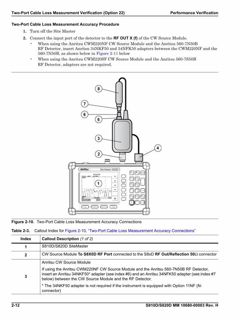
Two-Port Cable Loss Measurement Accuracy Procedure
1. Turn off the Site Master
2. Connect the input port of the detector to the RF OUT X (f) of the CW Source Module. • When using the Anritsu CWM220NF CW Source Module and the Anritsu 560-7N50B
RF Detector, insert Anritsu 34NKF50 and 34NFK50 adapters between the CWM220NF and the 560-7N50B, as shown below in Figure 2-11 below
• When using the Anritsu CWM220SF CW Source Module and the Anritsu 560-7S50B RF Detector, adapters are not required.
Figure 2-10. Two-Port Cable Loss Measurement Accuracy Connections
Table 2-3. Callout Index for Figure 2-10, “Two-Port Cable Loss Measurement Accuracy Connections”
Index Callout Description (1 of 2)
1 S810D/S820D SiteMaster
2 CW Source Module To S8X0D RF Port connected to the S8xD RF Out/Reflection 50Ω connector
3
Anritsu CW Source Module
If using the Anritsu CWM220NF CW Source Module and the Anritsu 560-7N50B RF Detector, insert an Anritsu 34NKF50* adapter (see index #6) and an Anritsu 34NFK50 adapter (see index #7 below) between the CW Source Module and the RF Detector.
* The 34NKF50 adapter is not required if the instrument is equipped with Option 11NF (N-connector)

Performance Verification Two-Port Cable Loss Measurement Verification (Option 22)
S810D/S820D MM 10680-00003 Rev. H 2-13
3. Connect the cable of the detector to the DETECTOR INPUT of the CW Source Module.
4. Connect the TO S8X0D RF PORT X-TYPE of the CW Source Module to RF OUT of S8x0D.
5. Connect the cable of the CW Source Module to the CW Source Module Interface port of the S8x0D.
6. Press and hold the ESCAPE/CLEAR key, then press the ON/OFF key to turn on the S8x0D.
7. Let the S8x0D warm up for 15 minutes.
8. Press MODE hard key.
9. Use the Up/Down arrow key to highlight Cable Loss – Two Port, then press ENTER.
10. Press START CAL, then press ENTER.
4CW Source Module CW Source Module Interface port connected to the S8x0D CW Source Module Interface
5 CW Source Module RF Out port.
6Adapter, Anritsu 34NKF50 adapter, N(m) to K (f). Only required if using a CWM220NF CW Source Module and a 560-7N50B RF Detector.
7Adapter, Anritsu 34NFK50 adapter, N(f) to K (m). Only required if using a CWM220NF CW Source Module and a 560-7N50B RF Detector.
8 RF Detector, Anritsu 560-7N50B or Anritsu 560-7S50B.
Table 2-3. Callout Index for Figure 2-10, “Two-Port Cable Loss Measurement Accuracy Connections”
Index Callout Description (2 of 2)
Two-Port Cable Loss Measurement Verification (Option 22) Performance Verification
2-14 S810D/S820D MM 10680-00003 Rev. H
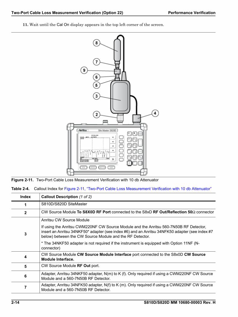
11. Wait until the Cal On display appears in the top left corner of the screen.
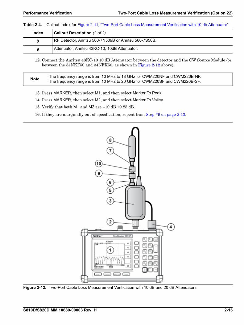
Figure 2-11. Two-Port Cable Loss Measurement Verification with 10 db Attenuator
Table 2-4. Callout Index for Figure 2-11, “Two-Port Cable Loss Measurement Verification with 10 db Attenuator”
Index Callout Description (1 of 2)
1 S810D/S820D SiteMaster
2 CW Source Module To S8X0D RF Port connected to the S8xD RF Out/Reflection 50Ω connector
3
Anritsu CW Source Module
If using the Anritsu CWM220NF CW Source Module and the Anritsu 560-7N50B RF Detector, insert an Anritsu 34NKF50* adapter (see index #6) and an Anritsu 34NFK50 adapter (see index #7 below) between the CW Source Module and the RF Detector.
* The 34NKF50 adapter is not required if the instrument is equipped with Option 11NF (N-connector)
4CW Source Module CW Source Module Interface port connected to the S8x0D CW Source Module Interface.
5 CW Source Module RF Out port.
6Adapter, Anritsu 34NKF50 adapter, N(m) to K (f). Only required if using a CWM220NF CW Source Module and a 560-7N50B RF Detector.
7Adapter, Anritsu 34NFK50 adapter, N(f) to K (m). Only required if using a CWM220NF CW Source Module and a 560-7N50B RF Detector.
Performance Verification Two-Port Cable Loss Measurement Verification (Option 22)
S810D/S820D MM 10680-00003 Rev. H 2-15
12. Connect the Anritsu 43KC-10 10 dB Attenuator between the detector and the CW Source Module (or between the 34NKF50 and 34NFK50, as shown in Figure 2-12 above).
13. Press MARKER, then select M1, and then select Marker To Peak.14. Press MARKER, then select M2, and then select Marker To Valley.15. Verify that both M1 and M2 are –10 dB ±0.85 dB.
16. If they are marginally out of specification, repeat from Step #9 on page 2-13.
8 RF Detector, Anritsu 560-7N509B or Anritsu 560-7S50B.
9 Attenuator, Anritsu 43KC-10, 10dB Attenuator.
NoteThe frequency range is from 10 MHz to 18 GHz for CWM220NF and CWM220B-NF.The frequency range is from 10 MHz to 20 GHz for CWM220SF and CWM220B-SF.
Figure 2-12. Two-Port Cable Loss Measurement Verification with 10 dB and 20 dB Attenuators
Table 2-4. Callout Index for Figure 2-11, “Two-Port Cable Loss Measurement Verification with 10 db Attenuator”
Index Callout Description (2 of 2)
Two-Port Cable Loss Measurement Verification (Option 22) Performance Verification
2-16 S810D/S820D MM 10680-00003 Rev. H
17. Add the 43KC-20 attenuator to the 43KC-10 attenuator to make 30 dB attenuation.
18. Press MARKER, select M1, select Marker To Peak.
19. Press MARKER, select M2, select Marker To Valley. 20. Verify that both M1 and M2 are –30 dB ±1.35 dB.
21. If M1 and M2 are marginally out of specification, repeat from Step #9 on page 2-13, but skip Step #12, Step #13, and Step #14, and then continuing with the rest of this procedure.
Table 2-5. Callout Index for Figure 2-12, “Two-Port Cable Loss Measurement Verification with 10 dB and 20 dB Attenuators”
Index Callout Description
1 S810D/S820D SiteMaster
2 CW Source Module To S8X0D RF Port connected to the S8xD RF Out/Reflection 50Ω connector
3
Anritsu CW Source Module
If using the Anritsu CWM220NF CW Source Module and the Anritsu 560-7N50B RF Detector, insert an Anritsu 34NKF50* adapter (see #6 below) and an Anritsu 34NFK50 adapter (see #7 below) between the CW Source Module and the RF Detector.
* The 34NKF50 adapter is not required if the instrument is equipped with Option 11NF (N-connector)
4CW Source Module CW Source Module Interface port connected to the S8x0D CW Source Module Interface
5 CW Source Module RF Out port.
6Adapter, Anritsu 34NKF50 adapter, N(m) to K (f). Only required if using a CWM220NF CW Source Module and a 560-7N50B RF Detector.
7Adapter, Anritsu 34NFK50 adapter, N(f) to K (m). Only required if using a CWM220NF CW Source Module and a 560-7N50B RF Detector.
8 RF Detector, Anritsu 560-7N50B or Anritsu 560-7S50B.
9 Attenuator, Anritsu 43KC-10, 10dB Attenuator.
10 Attenuator, Anritsu 43KC-20, 20 dB Attenuator.
S810D/S820D MM 10680-00003 Rev. H 3-1
Chapter 3 — Removal and Replacement
3-1 IntroductionThe removal and replacement chapter provides the following sections, information, and procedures:
• Section 3-2, “Accessories, Parts, and Hardware” on page 3-2
• “Accessories” on page 3-2
• “Replaceable Parts” on page 3-3
• “Hardware” on page 3-3
• “Case Parts” on page 3-4
• Section 3-3, “Battery Pack Removal and Replacement” on page 3-5
• Section 3-4, “Battery General Information” on page 3-7
• Section 3-5, “Battery Testing Procedure” on page 3-8
• Section 3-6, “Front Panel Assembly Removal and Replacement” on page 3-9
• Section 3-7, “LCD Assembly Replacement” on page 3-11
• Section 3-8, “Keypad PCB Replacement” on page 3-12
• Section 3-9, “Keypad Membrane Replacement” on page 3-13
• Section 3-10, “Power Monitor PCB Replacement” on page 3-14
• Section 3-11, “Real Time Clock Battery Replacement” on page 3-15
• Section 3-12, “Main/RF PCB Assembly Replacement” on page 3-16
• Section 3-13, “Source Control PCB Assembly Replacement” on page 3-18

Accessories, Parts, and Hardware Removal and Replacement
3-2 S810D/S820D MM 10680-00003 Rev. H
3-2 Accessories, Parts, and Hardware
Accessories
Table 3-1. S810D/S820D Site Master Accessories
Part Number Description Qty
10680-00001 User’s Guide, Site Master S810D and S820D 1
10680-00002 Programming Manual, Site Master S810D and S820D (disk only) 1
2300-347 Handheld Software Tools 1
40-187-R AC/DC Adapter 1
2000-1029 Battery Charger 1
806-141 Automotive Power Adapter 1
65717 Soft Carrying Case 1
800-441 Serial Interface Cable Assembly 1
551-1961-R USB to RS232 Adapter Cable 1
22N50 Open/Short, N(m) 1
28N50-2 Precision Termination, N(m) 1
22K50 Open/Short, K (m) 1
28K50 Precision Termination, K (m) 1
34NFK50 Adapter, N(m) to K (f) 1
SC6815 Calibration/Verification Kit 1

Removal and Replacement Accessories, Parts, and Hardware
S810D/S820D MM 10680-00003 Rev. H 3-3
Replaceable Parts
Hardware
Table 3-2. S810D/S820D Site Master Replaceable Parts
Part Number Description Qty
15-123 Color Liquid Crystal Display Assembly 1
551-1694 Adapter, 2-Row 32-Pin Inter-Connect Adapter (m-m) for Option PCB 1
633-26 Lithium Coin Real-Time Clock Battery 1
633-27 Rechargeable Battery, NiMH 1
46649-4 Membrane Keypad, Main 1
3-71657-3 Keypad PCB Assembly 1
ND64376 Power Monitor PCB Assembly 1
ND66448 Main/RF PCB Exchange Assembly, S810D 1
ND66449 Main/RF PCB Exchange Assembly, S810D with Option 11NF 1
ND66450 Main/RF PCB Exchange Assembly, S820D 1
ND66451 Main/RF PCB Exchange Assembly, S820D with Option 11NF 1
ND67171 Exchange Module, CWM220NF 1
ND67172 Exchange Module, CWM220SF 1
ND68537 Source Control PCB Exchange Assembly, S8x0D, part of Option 22, Two-Port Cable Loss Measurement, provides control for external CW Source Module, CWM220xF
1
Table 3-3. S810D/S820D Site Master Hardware
Part Number Description Qty
900-861 Pan Head Screw, 4-20, 0.365 19
900-791 Screw, 2-56, 0.375 77
900-720 Screw, 4-40, 0.187 6
900-326 Kep Nut, 4-40, 0.187 3
790-18 M-F Standoff, 4-40, 0.375, Hex 4
785-405 Plain Standoff, 4-40, 0.187, Hex 4
785-927 M-F Standoff, 4-40, 0.625 3
761-79 Cap Vinyl, Black, Round 2
Accessories, Parts, and Hardware Removal and Replacement
3-4 S810D/S820D MM 10680-00003 Rev. H
Case Parts
Table 3-4. S810D/S820D Site Master Case Parts
Part Number Description Qty
61440-1 Top Case 1
46653-3 Bottom Case 1
48231-3 Battery Door 1
790-509, 790-510, and 48241 Battery Door Latch (3 pieces) 1
790-515 Spring, Battery Compartment 1
790-551 Door Lock Receptacle 1
46655 Case Corner Bumpers 4
62934 ID Label, Model S820D 1
62935 ID Label, Model S810D 1

Removal and Replacement Battery Pack Removal and Replacement
S810D/S820D MM 10680-00003 Rev. H 3-5
3-3 Battery Pack Removal and ReplacementThis procedure provides instructions for removing and replacing the Site Master battery pack.
1. With the Site Master standing upright on a stable surface, locate the battery access door (see Figure 3-1).
2. Lift up the access door handle and rotate it 90 degrees counterclockwise.
3. Lift the door and remove the door.
4. Grasp the battery lanyard and pull the battery straight up and out of the unit, as illustrated in Figure 3-1 above.
NoteMany of the procedures in this section are generic, and apply to many similar instruments. Photos and illustrations used are representative and may show instruments other than the Site Master.
Figure 3-1. Removing the Battery Access Door

Battery Pack Removal and Replacement Removal and Replacement
3-6 S810D/S820D MM 10680-00003 Rev. H
5. Replacement is the opposite of removal. Note the orientation of the battery contacts, and be sure to insert the new battery with the contacts facing the rear of the unit (Figure 3-2).
Figure 3-2. Battery Orientation

Removal and Replacement Battery General Information
S810D/S820D MM 10680-00003 Rev. H 3-7
3-4 Battery General InformationThe following information relates to the care and handling of the Site Master battery, and NiMH batteries in general.
Anritsu Batteries and Chargers
• Use only Anritsu approved battery packs.
• Recharge the battery only in the Site Master or in an Anritsu-approved charger.
Battery General Care and Use
• Always use the battery for its intended purpose only.
• Never use a damaged or worn out charger or battery.
• Never short-circuit the battery terminals.
• Do not drop, mutilate or attempt to disassemble the battery.
Charging
• The Nickel Metal Hydride (NiMH) battery supplied with the Site Master is shipped in a discharged state.
• Before using the Site Master, the internal battery must first be charged for three hours, either in the Site Master or in the optional battery charger (Anritsu part number: 2000-1029).
• When the Site Master or battery charger is not in use, disconnect it from the power source.
• Do not charge batteries for longer than 24 hours; overcharging may shorten battery life.
• If left unused a fully charged battery will discharge itself over time.
Storage Temperatures
• Temperature extremes will affect the ability of the battery to charge. Allow the battery to cool down or warm up as necessary before use or charging.
• Storing the battery in extreme hot or cold places will reduce the capacity and lifetime of the battery.
Battery Conditioning
• With a new NiMH battery, full performance is achieved after three to five complete charge and discharge cycles.
• Discharge an NiMH battery from time to time to improve battery performance and battery life.
Battery Replacement and Disposal
• The battery can be charged and discharged hundreds of times, but it will eventually wear out.
• The battery may need to be replaced when the operating time between charging becomes noticeably shorter than normal.
• Do not dispose of batteries in a fire!
• Batteries must be recycled or disposed of properly.
• Do not place batteries in household garbage.
Battery Testing Procedure Removal and Replacement
3-8 S810D/S820D MM 10680-00003 Rev. H
3-5 Battery Testing ProcedureThe following procedure describes how to test the battery.
1. With the Site Master off and the battery installed, connect the Universal AC Adapter to the 12.5-15VDC (1350 mA) connector. The External Power LED and the Battery Charging LED will light.
2. Disconnect the AC-DC Adapter when the Battery Charging LED turns off, indicating the battery is fully charged.
3. Press and hold the ESCAPE/CLEAR key, then press the ON/OFF key to turn on the Site Master. This sets the instrument to the factory preset state. Press ENTER when prompted to continue.
4. Press the SYS key, followed by the Status soft key. Verify that the indicated battery charge is greater than or equal to 80%. • If the value is 80% or above, press the ESCAPE/CLEAR key and continue with this procedure. • If the value is lower than 80%, a discharge/charge cycle may be needed to improve the battery
capacity. - Completely discharge the battery, as described in Step #5 and Step #6 below.- Then recharge the battery as described in Step #1 and Step #2 above.
• If the battery capacity does not increase after a discharge/charge cycle, replace the battery.
5. Press the START CAL key (to keep the Site Master from going into HOLD mode) and make note of the test start time.
6. When the Site Master display fades and the Site Master switches itself off, make note of the test stop time.
7. The total test time from Step #5 to Step #6 should be greater than or equal to 1.5 hours.
8. If the battery charge started at 80% or more and the total battery test time is less than 70 minutes, replace the battery.
Note
If the Battery Charging LED does not light, the battery may be too low to immediately start full charging. Leaving the unit connected to AC power for several hours may bring the battery up to a level where full charging can begin. Turn the unit off and back on to see if the Battery Charging LED lights indicating a full charge cycle has begun. Charging is inhibited below 0ºC (0 degrees C) and above 45ºC (45 degrees C). If the unit is too hot, the battery will not start charging until the unit temperature has reached 43ºC (43 degrees C).

Removal and Replacement Front Panel Assembly Removal and Replacement
S810D/S820D MM 10680-00003 Rev. H 3-9
3-6 Front Panel Assembly Removal and Replacement
Overview
This procedure provides instructions for removing and replacing the Site Master front panel assembly. With the front panel assembly removed, the LCD display, keypad PCB, keypad membrane, and main PCB assemblies can be removed and replaced.
Replacement Procedure
1. Place the Site Master face up on a stable work surface.
2. Remove the four rubber corner bumpers by carefully lifting and sliding the bumpers off of the case corners (Figure 3-3).
3. With the bumpers removed, the access holes for the case screws are revealed.
4. Use a Phillips screwdriver to remove the four screws securing the two halves of the Site Master case together.
5. Carefully lift up on the right side (as viewed from the front) of the front half of the case and begin to separate the two halves.
6. Carefully disconnect the LCD display cable from J14 on the main PCB.
7. Carefully disconnect the keypad interface cable from J4 on the main PCB.
8. Carefully disconnect the LCD display backlight cable from J1 on the main PCB.
9. Remove the front panel assembly.
NoteMany of the procedures in this section are generic, and apply to many similar instruments. Photos and illustrations used are representative and may show instruments other than the Site Master.
Figure 3-3. Remove the Corner Bumpers
CautionDo not force or pull the two halves of the case apart completely, as there are delicate cables attached between the two halves that must be disconnected first.

Front Panel Assembly Removal and Replacement Removal and Replacement
3-10 S810D/S820D MM 10680-00003 Rev. H
10. Reverse the above steps to replace the front panel assembly.
Note The corner bumpers only mount one way. That is, the raised area inside one end of the bumper (Figure 12) is made to conform to the contour of the front cover only.
Figure 3-4. Corner Bumper Detail with Raised Area
Removal and Replacement LCD Assembly Replacement
S810D/S820D MM 10680-00003 Rev. H 3-11
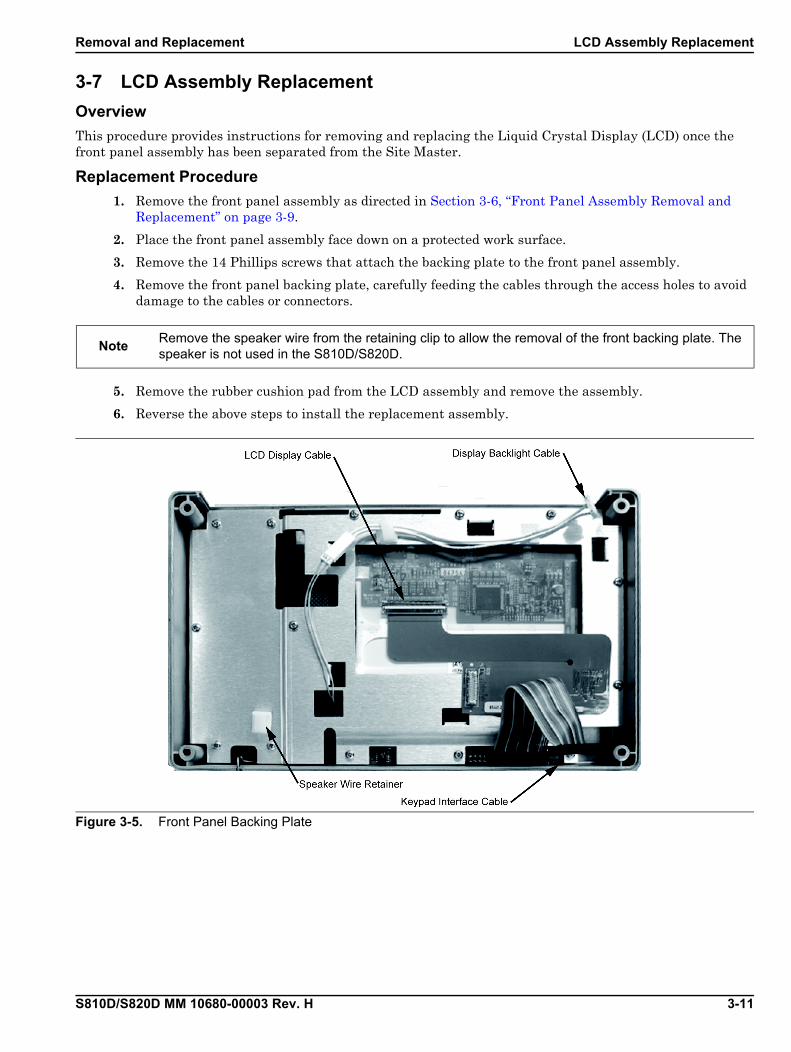
3-7 LCD Assembly Replacement
Overview
This procedure provides instructions for removing and replacing the Liquid Crystal Display (LCD) once the front panel assembly has been separated from the Site Master.
Replacement Procedure
1. Remove the front panel assembly as directed in Section 3-6, “Front Panel Assembly Removal and Replacement” on page 3-9.
2. Place the front panel assembly face down on a protected work surface.
3. Remove the 14 Phillips screws that attach the backing plate to the front panel assembly.
4. Remove the front panel backing plate, carefully feeding the cables through the access holes to avoid damage to the cables or connectors.
5. Remove the rubber cushion pad from the LCD assembly and remove the assembly.
6. Reverse the above steps to install the replacement assembly.
NoteRemove the speaker wire from the retaining clip to allow the removal of the front backing plate. The speaker is not used in the S810D/S820D.
Figure 3-5. Front Panel Backing Plate

Keypad PCB Replacement Removal and Replacement
3-12 S810D/S820D MM 10680-00003 Rev. H
3-8 Keypad PCB Replacement
Overview
This procedure provides instructions for removing and replacing the keypad PCB.
Replacement Procedure
1. Remove the front panel assembly as directed in Section 3-6, “Front Panel Assembly Removal and Replacement” on page 3-9.
2. Place the front panel assembly face down on a protected work surface.
3. Remove the 14 Phillips screws that attach the backing plate to the front panel assembly.
4. Remove the front panel backing plate, carefully feeding the cables through the access holes to avoid damage to the cables or connectors.
5. Remove the rubber cushion pad from the key pad PCB and remove the PCB.
6. Reverse the steps above steps to install the replacement assembly.
Figure 3-6. Front Panel Keypad PCB Location
Removal and Replacement Keypad Membrane Replacement
S810D/S820D MM 10680-00003 Rev. H 3-13
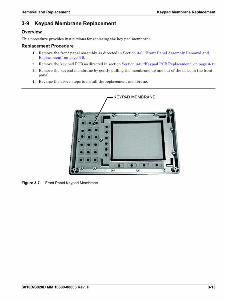
3-9 Keypad Membrane Replacement
Overview
This procedure provides instructions for replacing the key pad membrane.
Replacement Procedure
1. Remove the front panel assembly as directed in Section 3-6, “Front Panel Assembly Removal and Replacement” on page 3-9.
2. Remove the key pad PCB as directed in section Section 3-8, “Keypad PCB Replacement” on page 3-12
3. Remove the keypad membrane by gently pulling the membrane up and out of the holes in the front panel.
4. Reverse the above steps to install the replacement membrane.
Figure 3-7. Front Panel Keypad Membrane
Power Monitor PCB Replacement Removal and Replacement
3-14 S810D/S820D MM 10680-00003 Rev. H
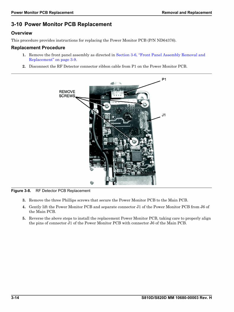
3-10 Power Monitor PCB Replacement
Overview
This procedure provides instructions for replacing the Power Monitor PCB (P/N ND64376).
Replacement Procedure
1. Remove the front panel assembly as directed in Section 3-6, “Front Panel Assembly Removal and Replacement” on page 3-9.
2. Disconnect the RF Detector connector ribbon cable from P1 on the Power Monitor PCB.
3. Remove the three Phillips screws that secure the Power Monitor PCB to the Main PCB.
4. Gently lift the Power Monitor PCB and separate connector J1 of the Power Monitor PCB from J6 of the Main PCB.
5. Reverse the above steps to install the replacement Power Monitor PCB, taking care to properly align the pins of connector J1 of the Power Monitor PCB with connector J6 of the Main PCB.
Figure 3-8. RF Detector PCB Replacement
Removal and Replacement Real Time Clock Battery Replacement
S810D/S820D MM 10680-00003 Rev. H 3-15
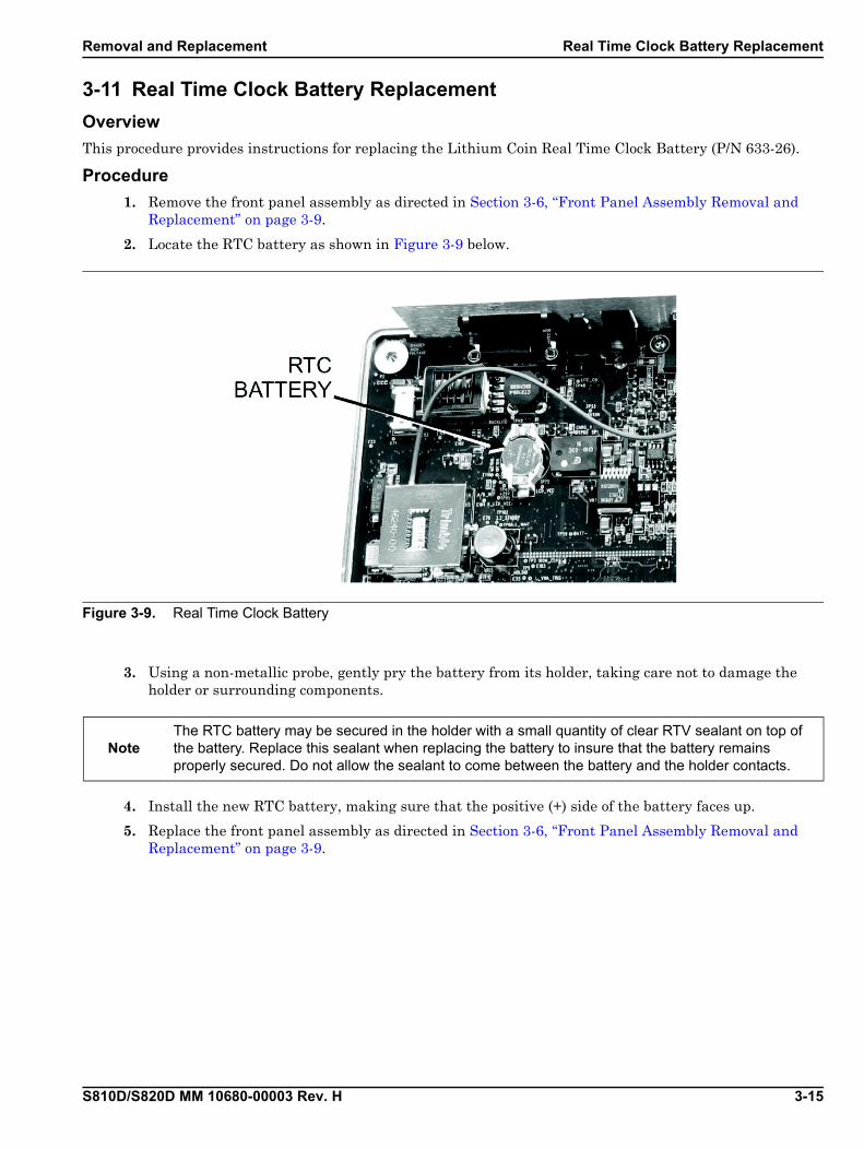
3-11 Real Time Clock Battery Replacement
Overview
This procedure provides instructions for replacing the Lithium Coin Real Time Clock Battery (P/N 633-26).
Procedure
1. Remove the front panel assembly as directed in Section 3-6, “Front Panel Assembly Removal and Replacement” on page 3-9.
2. Locate the RTC battery as shown in Figure 3-9 below.
3. Using a non-metallic probe, gently pry the battery from its holder, taking care not to damage the holder or surrounding components.
4. Install the new RTC battery, making sure that the positive (+) side of the battery faces up.
5. Replace the front panel assembly as directed in Section 3-6, “Front Panel Assembly Removal and Replacement” on page 3-9.
Figure 3-9. Real Time Clock Battery
NoteThe RTC battery may be secured in the holder with a small quantity of clear RTV sealant on top of the battery. Replace this sealant when replacing the battery to insure that the battery remains properly secured. Do not allow the sealant to come between the battery and the holder contacts.

Main/RF PCB Assembly Replacement Removal and Replacement
3-16 S810D/S820D MM 10680-00003 Rev. H
3-12 Main/RF PCB Assembly Replacement
Overview
This procedure provides instructions for replacing the Main/RF PCB assembly.
Replacement Procedure
1. Remove the front panel assembly as directed in Section 3-6, “Front Panel Assembly Removal and Replacement” on page 3-9.
2. Disconnect the battery connector from J7 on the Main PCB.
3. Disconnect the semi-rigid coaxial cable from the RF PCB, as indicated in Figure 3-10 below.
4. Disconnect the RF Detector connector ribbon cable from P1 on the Power Monitor PCB.
5. Remove the PCB mounting screws and the GPS and Serial Interface connector mounting fasteners.
6. Remove the GPS connector from the connector panel.
7. Carefully lift the top of the Main PCB up and clear of the connector panel.
8. Fold the Main PCB back to allow access to the RF PCB below and remove the three 0.25” standoffs that secure the RF PCB to the case (Figure 3-11).
9. Remove the Main/RF PCB assembly with the connector panel.
10. Reverse the steps above to install the new Main/RF PCB assembly.
NoteSome photos and steps in this procedure may vary depending on the options installed in the unit. Disregard any steps that do not apply to the specific unit being serviced.
Figure 3-10. Main/RF PCB Assembly
NoteThe connector panel fits into grooves in the two halves of the case. Make sure the panel is correctly aligned with the grooves before reassembling the two halves together.

Removal and Replacement Main/RF PCB Assembly Replacement
S810D/S820D MM 10680-00003 Rev. H 3-17
Figure 3-11. Main/RF PCB Removal
Table 3-5. Callout Index for Figure 3-11, “Main/RF PCB Removal”
Index Callout Description
1 Remove the three (3) 0.25” standoffs that secure the RF PCB to the case.
Source Control PCB Assembly Replacement Removal and Replacement
3-18 S810D/S820D MM 10680-00003 Rev. H
3-13 Source Control PCB Assembly Replacement
Overview
This procedure provides instructions for replacing the Option 22 CW Source Control PCB assembly.
Replacement Procedure
1. Remove the front panel assembly as directed in Section 3-6, “Front Panel Assembly Removal and Replacement” on page 3-9.
2. Place the instrument with the display and front panel buttons facing down.
NoteSome photos and steps in this procedure may vary depending on the options installed in the unit. Disregard any steps that do not apply to the specific unit being serviced.
Caution If the Option 22 CW Source Control PCB assembly removal procedure is done incorrectly, it can bend or break the pins on the 551-1694 2-row 32-pit (m-m) adapter that connects the Option 22 PCB assembly to the Main PCB assembly. It is highly recommended to only perform this procedure when spare 551-1694 adapters are available.
Removal and Replacement Source Control PCB Assembly Replacement
S810D/S820D MM 10680-00003 Rev. H 3-19
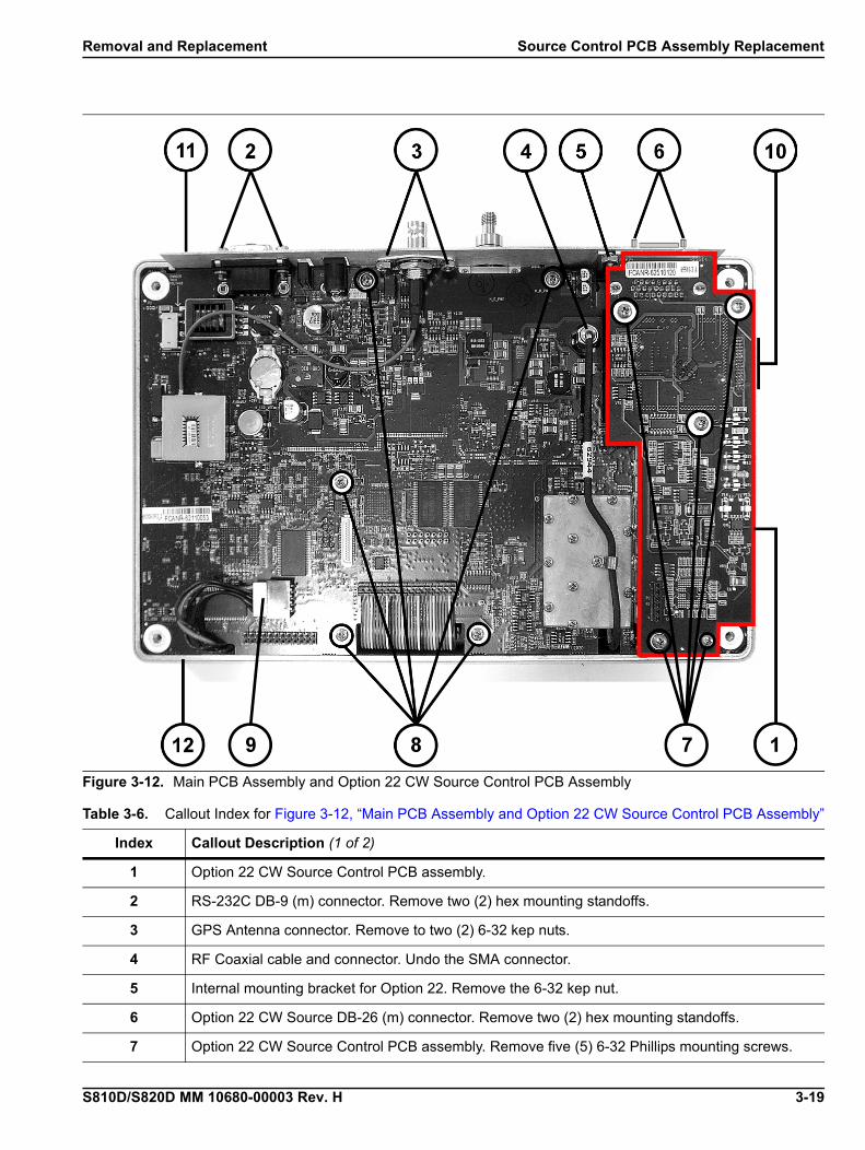
Figure 3-12. Main PCB Assembly and Option 22 CW Source Control PCB Assembly
Table 3-6. Callout Index for Figure 3-12, “Main PCB Assembly and Option 22 CW Source Control PCB Assembly”
Index Callout Description (1 of 2)
1 Option 22 CW Source Control PCB assembly.
2 RS-232C DB-9 (m) connector. Remove two (2) hex mounting standoffs.
3 GPS Antenna connector. Remove to two (2) 6-32 kep nuts.
4 RF Coaxial cable and connector. Undo the SMA connector.
5 Internal mounting bracket for Option 22. Remove the 6-32 kep nut.
6 Option 22 CW Source DB-26 (m) connector. Remove two (2) hex mounting standoffs.
7 Option 22 CW Source Control PCB assembly. Remove five (5) 6-32 Phillips mounting screws.

Source Control PCB Assembly Replacement Removal and Replacement
3-20 S810D/S820D MM 10680-00003 Rev. H
3. Outside the case, remove two (2) hex standoffs from the RS-232C DB-9 (m) connector (Figure 3-12 #2).
4. Inside the case, remove two (2) 6-32 kep nuts from the GPS connector (Figure 3-12 #3).
5. Disconnect the semi-rigid coaxial cable SMA connector from the RF PCB. Leave the cable in place (Figure 3-12 #4).
6. Remove the 6-32 kep nut holding the Connector Adapter Plate in place. The plate will be lose but not removable at this point (Figure 3-12 #5).
7. Outside the case, remove two (2) hex standoffs from the Option 22 CW Source DB-26 (m) connector (Figure 3-12 #6).
8. Inside the case, remove five (5) 6-32 Phillips mounting screws holding the Option 22 CW Source Control PCB assembly in place (Figure 3-12 #7).
9. Remove five (5) 6-32 Phillips mounting screws holding the Main PCB assembly in place (Figure 3-12 #8).
10. Disconnect the battery connector from J7 on the Main PCB (Figure 3-12 #9).
11. The Connector Panel, Main PCB, and the Option 22 CW Source Module assemblies should be loose.
12. Gently lift the bottom edge of the Main PCB assembly closest to the ribbon cable (Figure 3-12 #11) and gently pull towards the bottom of the case. The goal is to create clearance between the Connector Panel and the Main PCB assembly.
13. Gently lift the Connector Panel assembly (Figure 3-12 #12) and pull it towards the top of the instrument. The goal is to create more clearance between the Connector Panel and the DB-26 connector on the Option 22 CW Source Control PCB assembly.
14. Finally, gently lift the back edge of the Option 22 CW Source Control assembly.
15. When the Option 22 DB-26 connector is free from the Connector Panel, continue to lift the Option 22 CW Source Control PCB assembly.
16. Inspect the pins on the 551-1694 2-row 32-pin (m-m) adapter. If they are bent, replace the adapter.
17. Installation of the replacement Option 22 CW Source Control PCB assembly is the reverse process.
18. Start with installing the 551-1694 2-row 32-pin (m-m) adapter on the Main PCB.
19. Make sure the Connector Adapter Plate is in place and that the slot on the Plate is correctly positioned around the 6-32 mounting stud on the inside of the Back Panel.
8 Main PCB assembly. Remove five (5) 6-32 Phillips mounting screws.
9 Main PCB assembly. Disconnect the battery connector from J7.
10
Out of view and mounted on the other side of the Option 22 PCB assembly is the 2-Row 32-Socket Interconnect Header Connector. Below that is the 551-1694 2-row 32-pin (m-m) adapter. The adapter connects to a second 2-Row 32-Socket Interconnect Header Connector mounted on the Main PCB.
11 Connector panel and top of instrument.
12 Bottom of instrument
NoteConnecting the 2-row 32-pin header connectors on the Option 22 and Main PCB assemblies is the 551-1694 2-row 32-pin (m-m) adapter. The 32-pin adapter may remain in the Main PCB assembly or stay with the Option 22 PCB assembly.
Table 3-6. Callout Index for Figure 3-12, “Main PCB Assembly and Option 22 CW Source Control PCB Assembly”
Index Callout Description (2 of 2)
Removal and Replacement Source Control PCB Assembly Replacement
S810D/S820D MM 10680-00003 Rev. H 3-21
20. Insert the DB-26 connector through the Connector Adapter Plate and Connector Panel openings.
21. When DB-26 connector is through the Connector Panel opening, gently lower the Option 22 CW Source Control PCB assembly onto the Main PBC, making sure the header on the Option 22 header connects successfully with the 551-1694 2-row 32-pin (m-m) adapter.
22. Once the headers and adapter have successfully connected, begin to add but not tighten the remaining hardware.
23. Reconnect the J5 power connector.
24. Tighten the Phillips screws holding the Main PCB assembly.
25. Tighten the Phillips screws holding the Option 22 CW Source Control PSCB assembly.
26. Tighten the hex standoff nuts on the DB-26 connector.
27. Tighten the 6-32 kep nut holding the Connector Adapter panel in place.
28. Tighten the RF coax connector.
29. Tighten the 6-32 kep nuts holding the GPS connector.
30. Tighten the hex standoff nuts on the RS-232C DB-9 serial connector.

Source Control PCB Assembly Replacement Removal and Replacement
3-22 S810D/S820D MM 10680-00003 Rev. H

S810D/S820D MM 10680-00003 Rev. H A-1
Appendix A — Test Data Master for CW Source Modules
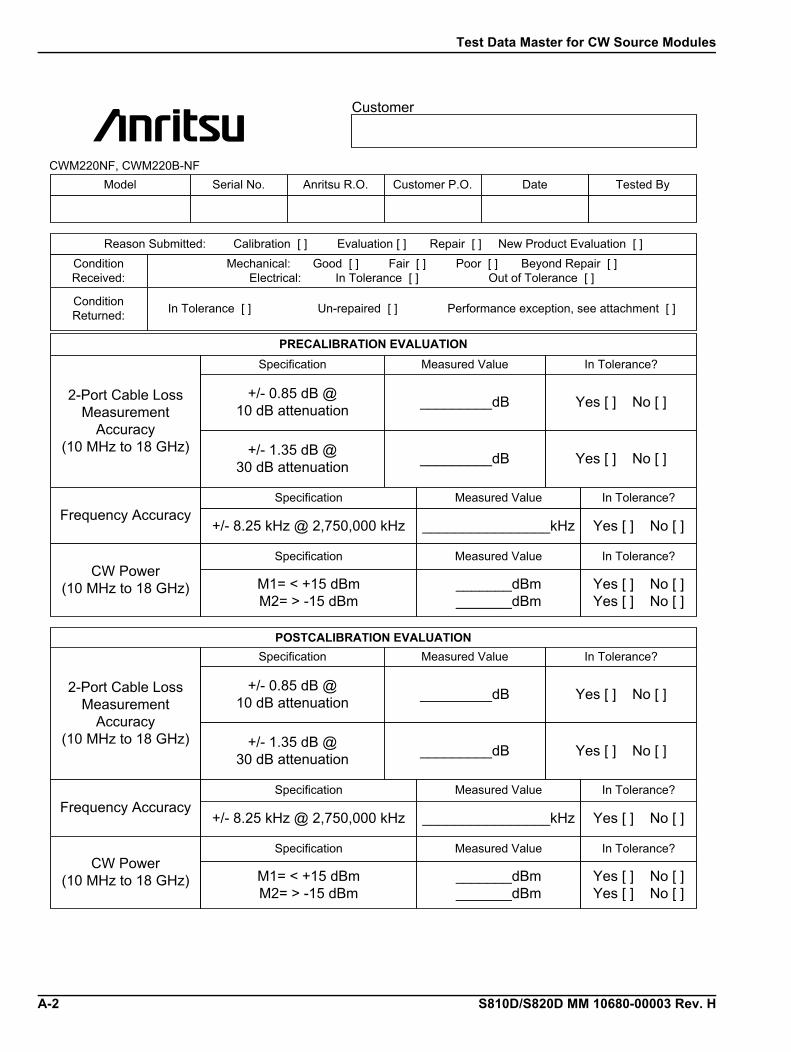
Test Data Master for CW Source Modules
A-2 S810D/S820D MM 10680-00003 Rev. H
Customer
Model Serial No. Anritsu R.O. Customer P.O. Date Tested By
Reason Submitted: Calibration [ ] Evaluation [ ] Repair [ ] New Product Evaluation [ ]Condition Received:
Mechanical: Good [ ] Fair [ ] Poor [ ] Beyond Repair [ ]Electrical: In Tolerance [ ] Out of Tolerance [ ]
ConditionReturned: In Tolerance [ ] Un-repaired [ ] Performance exception, see attachment [ ]
PRECALIBRATION EVALUATION
POSTCALIBRATION EVALUATION
2-Port Cable Loss Measurement
Accuracy(10 MHz to 18 GHz)
Specification Measured Value In Tolerance?
+/- 0.85 dB @10 dB attenuation _________dB Yes [ ] No [ ]
+/- 1.35 dB @30 dB attenuation _________dB Yes [ ] No [ ]
CWM220NF, CWM220B-NF
Frequency AccuracySpecification Measured Value In Tolerance?
+/- 8.25 kHz @ 2,750,000 kHz ________________kHz Yes [ ] No [ ]
CW Power(10 MHz to 18 GHz)
Specification Measured Value In Tolerance?
M1= < +15 dBmM2= > -15 dBm
_______dBm_______dBm
Yes [ ] No [ ]Yes [ ] No [ ]
2-Port Cable Loss Measurement
Accuracy(10 MHz to 18 GHz)
Specification Measured Value In Tolerance?
+/- 0.85 dB @10 dB attenuation _________dB Yes [ ] No [ ]
+/- 1.35 dB @30 dB attenuation _________dB Yes [ ] No [ ]
Frequency AccuracySpecification Measured Value In Tolerance?
+/- 8.25 kHz @ 2,750,000 kHz ________________kHz Yes [ ] No [ ]
CW Power(10 MHz to 18 GHz)
Specification Measured Value In Tolerance?
M1= < +15 dBmM2= > -15 dBm
_______dBm_______dBm
Yes [ ] No [ ]Yes [ ] No [ ]
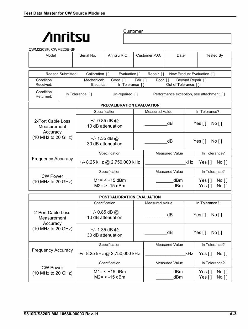
Test Data Master for CW Source Modules
S810D/S820D MM 10680-00003 Rev. H A-3
Customer
Model Serial No. Anritsu R.O. Customer P.O. Date Tested By
Reason Submitted: Calibration [ ] Evaluation [ ] Repair [ ] New Product Evaluation [ ]Condition Received:
Mechanical: Good [ ] Fair [ ] Poor [ ] Beyond Repair [ ]Electrical: In Tolerance [ ] Out of Tolerance [ ]
ConditionReturned: In Tolerance [ ] Un-repaired [ ] Performance exception, see attachment [ ]
PRECALIBRATION EVALUATION
POSTCALIBRATION EVALUATION
2-Port Cable Loss Measurement
Accuracy(10 MHz to 20 GHz)
Specification Measured Value In Tolerance?
+/- 0.85 dB @10 dB attenuation _________dB Yes [ ] No [ ]
+/- 1.35 dB @30 dB attenuation _________dB Yes [ ] No [ ]
CWM220SF, CWM220B-SF
Frequency AccuracySpecification Measured Value In Tolerance?
+/- 8.25 kHz @ 2,750,000 kHz ________________kHz Yes [ ] No [ ]
CW Power(10 MHz to 20 GHz)
Specification Measured Value In Tolerance?
M1= < +15 dBmM2= > -15 dBm
_______dBm_______dBm
Yes [ ] No [ ]Yes [ ] No [ ]
2-Port Cable Loss Measurement
Accuracy(10 MHz to 20 GHz)
Specification Measured Value In Tolerance?
+/- 0.85 dB @10 dB attenuation _________dB Yes [ ] No [ ]
+/- 1.35 dB @30 dB attenuation _________dB Yes [ ] No [ ]
Frequency AccuracySpecification Measured Value In Tolerance?
+/- 8.25 kHz @ 2,750,000 kHz ________________kHz Yes [ ] No [ ]
CW Power(10 MHz to 20 GHz)
Specification Measured Value In Tolerance?
M1= < +15 dBmM2= > -15 dBm
_______dBm_______dBm
Yes [ ] No [ ]Yes [ ] No [ ]

Test Data Master for CW Source Modules
A-4 S810D/S820D MM 10680-00003 Rev. H
Numerics to C
S810D/S820D MM 10680-00003 Rev. H Index-1
IndexNumerics
2 MHz Frequency Extension, Option 2 . . . . . . . . 1-42-Port Cable Loss Measurements, Option 22NF 1-42-Port Cable Loss Measurements, Option 22SF . 1-42-Row 32-Pin (m-m) Adapter P/N 551-1694 3-18, 3-20
Aaccessories . . . . . . . . . . . . . . . . . . . . . . . . . . . . . . . 3-2AD/DC adapter . . . . . . . . . . . . . . . . . . . . . . . . . . . 3-2adapters . . . 1-4, 2-7, 2-12, 2-14, 2-16, 3-2, 3-18, 3-20Anritsu P/Ns
10680-00001 User Guide . . . . . . . . . . . . . 1-1, 3-210680-00002 Programming Manual . . . . 1-1, 3-210680-00002 User Guide . . . . . . . . . . . . . . . . . 1-115-123 Color Liquid Crystal Display Assembly 3-32000-1029 Battery Charger . . . . . . . . . . 3-2, 3-72000-933 DC Power Supply . . . . . . . . . . . . . . 1-422K50 Open/Short K(m) . . . . . . . . . . . . . . . . . 3-222N50 Open/Short N(m) . . . . . . . . . . . . . . . . . 3-22300-347 Handheld Software Tools . . . . . . . . 3-22300-488 Verification Software . . . . . . . . . . . 2-228K50 Precision Termination K(m) . . . . . . . . 3-228N50-2 Precision Termination N(m) . . . . . . 3-234NFK50 N(f) to K(m) Adapter . 2-7, 2-12, 2-14,
2-16, . . . . . . . . . . . . . . . . . . . . . . . . . . . . . . . 3-234NKF50 N(m) to K(f) Adapter 1-4, 2-7, 2-12, 2-14,
. . . . . . . . . . . . . . . . . . . . . . . . . . . . . . . . . . 2-1640-187-R External Power Supply 2-1, 2-2, 2-5, 3-243KC-10 10 dB Attenuator . . . . . . . . . . 2-7, 2-1643KC-20 20 dB Attenuator . . . . . . . . . . 2-7, 2-1646649-4 Membrane Keypad Main . . . . . . . . . 3-346653-3 Bottom Case . . . . . . . . . . . . . . . . . . . . 3-446655 Case Corner Bumper . . . . . . . . . . . . . . 3-448231-3 Battery Door . . . . . . . . . . . . . . . . . . . 3-448241 Battery Door Latch . . . . . . . . . . . . . . . . 3-452737-3 Keypad PCB Assembly . . . . . . . . . . . 3-3551-1694 2-Row 32-Pin (m-m) Adapter . . . . 3-18551-1961-R USB to RS232 Adapter Cable . . . 3-2560-7N50B RF Detector 1-4, 2-5, 2-7, 2-12, 2-13,
2-14560-7S50B RF Detector . . . . . . . . . . . . . 2-7, 2-1261440-1 Top Case . . . . . . . . . . . . . . . . . . . . . . 3-462934 ID Lablel S820D . . . . . . . . . . . . . . . . . . 3-462935 ID Label S810D . . . . . . . . . . . . . . . . . . 3-4633-26 Lithium Clock Battery . . . . . . . 3-3, 3-15633-27 Rechargeable Battery NiMH . . . . . . . 3-365717 Soft Carrying Case . . . . . . . . . . . . . . . . 3-2785-405 Plain Standoff . . . . . . . . . . . . . . . . . . 3-3785-927 M-F Standoff . . . . . . . . . . . . . . . . . . . 3-3790-18 M-F Standoff . . . . . . . . . . . . . . . . . . . . 3-3790-509 Battery Door Latch . . . . . . . . . . . . . . 3-4790-510 Battery Door Latch . . . . . . . . . . . . . . 3-4790-515 Sprint Battery Compartment . . . . . . 3-4
790-551 Door Lock Replacement . . . . . . . . . . 3-4800-441 Serial Interface Cable . . . . . 1-4, 2-2, 3-2806-141 Automotive Power Adapter . . . . . . . 3-2900-326 Kep Nut . . . . . . . . . . . . . . . . . . . . . . . 3-3900-720 Screw, Machine . . . . . . . . . . . . . . . . . 3-3900-791 Screw, Machine . . . . . . . . . . . . . . . . . 3-3900-861 Pan Head Screw . . . . . . . . . . . . . . . . 3-3CWM220NF
CW Source Module 2-7, 2-8, 2-12, 2-13, 2-14, 2-16
CWM220SFCW Source Module . . . . . . . . . 2-7, 2-8, 2-12
MA2418A RF Reference Source . . . . . . . .1-4, 2-5MF2412B Frequency Counter . . . . . . . . .1-4, 2-1ND64376 Power Monitor PCB Assembly . . . . 3-3ND66448 Main/RF PCB Exchange Assembly
S810D . . . . . . . . . . . . . . . . . . . . . . . . . . . . . 3-3ND66449 Main/RF PCB Exchange Assembly
S810D with Option 11NF . . . . . . . . . . . . . 3-3ND66450 Main/RF PCB Exchange Assembly
S820D . . . . . . . . . . . . . . . . . . . . . . . . . . . . . 3-3ND66451 Main/RF PCB Exchange Assembly
S820D with Option 11NF . . . . . . . . . . . . . 3-3ND67171 Exchange Module CWM220NF . . . 3-3ND67172 Exchange Module CWM220SF . . . 3-3S810D Site Master . . . . . . . . . . . . . . . . . . . . . 1-1S820D Site Master . . . . . . . . . . . . . . . . . . . . . 1-1SC6815 Calibration/Verification Kit 1-4, 2-2, 3-2
attenuators . . . . . . . . . . . . . . . . . . . . . . . . . . 2-7, 2-16Aeroflex/Weinschel 1-10 . . . . . . . . . . . . . . . . . 2-5Aeroflex/Weinschel 1-30 . . . . . . . . . . . . . . . . . 2-5
Bbatteries . . . . . . . . . . . . . . . . . . . . . . . . . . . . 3-3, 3-15battery
RTC (Real Time Clock) . . . . . . . . . . . . . . . . . 3-15battery charger . . . . . . . . . . . . . . . . . . . . . . . . . . . .3-2battery pack
general information . . . . . . . . . . . . . . . . . . . . . 3-7overcharging . . . . . . . . . . . . . . . . . . . . . . . . . . 3-7removal and replacement . . . . . . . . . . . . . . . . 3-5testing procedure . . . . . . . . . . . . . . . . . . . . . . . 3-8
Ccables . . . . . . . . . . . . . . . . . . . . . . . . . . . . 1-4, 2-2, 3-2case . . . . . . . . . . . . . . . . . . . . . . . . . . . . . . . . . 3-2, 3-4
parts . . . . . . . . . . . . . . . . . . . . . . . . . . . . . . . . . 3-4chargers . . . . . . . . . . . . . . . . . . . . . . . . . . . . . . . . .3-7clock battery
removal and replacement . . . . . . . . . . . . . . . 3-15connectors
Connector Adapter Plate . . . . . . . . . . .3-20, 3-21Connector Panel . . . . . . . . . . . . . . . . . . . . . . 3-21connector panel view . . . . . . . . . . . . . . . . . . . . 1-3

D to R
Index-2 S810D/S820D MM 10680-00003 Rev. H
DB-26 (m) . . . . . . . . . . . . . . . . . . . . . . . . . . . . 3-20External DC Power Port (Coaxial Power
Connector) . . . . . . . . . . . . . . . . . . . . . . . . . . 1-2GPS . . . . . . . . . . . . . . . . . . . . . . . . . . . . . . . . . 3-16GPS Antenna (BNC) . . . . . . . . . . . . . . . . . . . . 1-2RF Out/Reflection 50W . . . . . . . . . . . . . . . . . . 1-2RS-232 Serial Interface DB-9 (m) . . . . . . . . . . 1-2Test Port Connector 11NF . . . . . . . . . . . . . . . 1-4top panel view . . . . . . . . . . . . . . . . . . . . . . . . . 1-3
corner bumpers removal and replacement . . . . 3-10critical specifications . . . . . . . . . . . . . . . . . . . . . . 1-4CW power
verification procedure . . . . . . . . . . . . . . . . . . . 2-8CW Source Module Interface connector . . . . . . . 1-3
DDB-26 (m) connector . . . . . . . . . . . . . . . . . . . . . . 3-20detectors . . . . . . . . . . . . . . . 2-5, 2-7, 2-12, 2-13, 2-14distance-to-fault (DTF) . . . . . . . . . . . . . . . . . . . . . 1-1DTF . . . . . . . . . . . . . . . . . . . . . . . . . . . . . . . . . . . . 1-1
Eexternal power supply . . . . . . . . . . . . . . . . . . . . . 3-2Extrernal DC Power connector . . . . . . . . . . . . . . 1-3
Ffrequency ranges . . . . . . . . . . . . . . . . . . . . . . . . . . 1-1
25 MHz to 10.5 GHz S810D . . . . . . . . . . . . . . 1-125 MHz to 20 GHz S820D . . . . . . . . . . . . . . . . 1-1
front panelremoval and replacement . . . . . . . . . . . . . . . . 3-9
front panel keys . . . . . . . . . . . . . . . . . . . . . . . . . . 1-2
Ggeneral information
battery pack . . . . . . . . . . . . . . . . . . . . . . . . . . . 3-7GPS
antenna connector . . . . . . . . . . . . . . . . . . . . . 3-16GPS antenna connector . . . . . . . . . . . . . . 1-2, 1-3Option 31, GPS Receiver . . . . . . . . . . . . . . . . . 1-4
Hhardware . . . . . . . . . . . . . . . . . . . . . . . . . . . . . 3-2, 3-3
Kkeypad . . . . . . . . . . . . . . . . . . . . . . . . . . . . . . . . . . 3-3
membrane removal and replacement . . . . . . 3-13PCB removal and replacement . . . . . . . . . . . 3-12
keyshard keys . . . . . . . . . . . . . . . . . . . . . . . . . . . . . 1-2soft keys . . . . . . . . . . . . . . . . . . . . . . . . . . . . . . 1-2
LLCD assembly
removal and replacement . . . . . . . . . . . . . . . 3-11
MMain RF PCB
removal and replacement . . . . . . . . . . . . . . . 3-16
manuals and guides . . . . . . . . . . . . . . . . . . . . . . . .3-2Programming Manual P/N 10680-00002 . . . . 1-1User Guide P/N 10680-00001 . . . . . . . . . . . . . 1-1
OOption 22 PCB assembly
DB-26 (m) connector . . . . . . . . . . . . . . . . . . . 3-20options
list of available options . . . . . . . . . . . . . . . . . . 1-4Option 11F, Test Port Connector . . . . . . . . . . 1-4Option 2, 2 MHz Frequency Extension . . . . . 1-4Option 22, CW Source Control Module PCB
Assembly . . . . . . . . . . . . . . . . . . . . . . . . . . 3-20Option 22, CW Source Control PCB . . . . . . . 3-18Option 22NF, 2-Port Cable Loss Measurements .
1-4Option 22SF, 2-Port Cable Loss Measurements .
1-4Option 31, GPS Receiver . . . . . . . . . . . . . . . . . 1-4Option 5, Power Monitor . . . . . . . . . . . . . . . . . 1-4
Pparts . . . . . . . . . . . . . . . . . . . . . . . . . . . . . . . . . . . .3-2
case . . . . . . . . . . . . . . . . . . . . . . . . . . . . . . . . . . 3-4hardware . . . . . . . . . . . . . . . . . . . . . . . . . . . . . 3-3list of replaceable parts . . . . . . . . . . . . . . 1-1, 3-3replacement procedures . . . . . . . . . . . . . . . . . 1-1
performanceverification procedures . . . . . . . . . . . . . . . . . . 1-1
power adapter . . . . . . . . . . . . . . . . . . . . . . . . . . . . .3-2Power Monitor
Option 5, Power Monitor . . . . . . . . . . . . . . . . . 1-4PCB removal and replacement . . . . . . . . . . . 3-14Power Monitor, Option 5 . . . . . . . . . . . . . . . . . 2-5verification test . . . . . . . . . . . . . . . . . . . . . . . . 2-5
proceduresbattery pack testing . . . . . . . . . . . . . . . . . . . . 3-8parts replacement . . . . . . . . . . . . . . . . . . . . . . 1-1
Programming Manual P/N 10680-00002 . . . 1-1, 3-2
Rreal-time clock battery . . . . . . . . . . . . . . . . . . . . .3-15recommended test equipment . . . . . . . . . . . . . . . .1-4removal and replacement
battery pack . . . . . . . . . . . . . . . . . . . . . . . . . . . 3-5clock battery . . . . . . . . . . . . . . . . . . . . . . . . . 3-15corner bumpers . . . . . . . . . . . . . . . . . . . . . . . 3-10front panel . . . . . . . . . . . . . . . . . . . . . . . . . . . . 3-9keypad . . . . . . . . . . . . . . . . . . . . . . . . . . . . . . 3-12keypad membrane . . . . . . . . . . . . . . . . . . . . . 3-13LCD assembly . . . . . . . . . . . . . . . . . . . . . . . . 3-11Main RF PCB . . . . . . . . . . . . . . . . . . . . . . . . . 3-16Option 22, CW Source Control PCB . . . . . . . 3-18Power Monitor PCB . . . . . . . . . . . . . . . . . . . . 3-14real-time clock battery . . . . . . . . . . . . . . . . . 3-15speaker wire clip . . . . . . . . . . . . . . . . . . . . . . 3-11
S to V
S810D/S820D MM 10680-00003 Rev. H Index-3
replacementparts list . . . . . . . . . . . . . . . . . . . . . . . . . . . . . . 1-1replacement part procedures . . . . . . . . . . . . . 1-1replacement parts . . . . . . . . . . . . . . . . . . . . . . 3-3
return loss . . . . . . . . . . . . . . . . . . . . . . . . . . . . . . . 1-1verification . . . . . . . . . . . . . . . . . . . . . . . . . . . . 2-2
RF Detector connector . . . . . . . . . . . . . . . . . . . . . 1-3RF Out/Reflection connector . . . . . . . . . . . . . . . . 1-3RS-232C DB-9 connector . . . . . . . . . . . . . . . . . . . 1-3RTC battery . . . . . . . . . . . . . . . . . . . . . . . . . . . . 3-15
SSafety Symbols
For Safety . . . . . . . . . . . . . . . . . . . . . . . . .Safety-2In Manuals . . . . . . . . . . . . . . . . . . . . . . . .Safety-1On Equipment . . . . . . . . . . . . . . . . . . . . .Safety-1
Site MasterS810 frequency range . . . . . . . . . . . . . . . . . . . 1-1S820D frequency range . . . . . . . . . . . . . . . . . . 1-1
software installation . . . . . . . . . . . . . . . . . . . . . . . 2-2speaker wire clip
removal and replacement . . . . . . . . . . . . . . . 3-11
Standing Wave Ratio (SWR) . . . . . . . . . . . . . . . . .1-1SWR . . . . . . . . . . . . . . . . . . . . . . . . . . . . . . . . . . . .1-1
Tterminators . . . . . . . . . . . . . . . . . . . . . . . . . . . . . . .3-2test equipment . . . . . . . . . . . . . . . . . . . . . . . . . . . .1-4Test Port Connector, Option 11NF . . . . . . . . . . . .1-4TFT color display . . . . . . . . . . . . . . . . . . . . . . . . . .1-3top panel connectors . . . . . . . . . . . . . . . . . . . . . . . .1-3two-port cable loss
measurement verification . . . . . . . . . . . . . . . . 2-7
UUser Guide P/N 10680-00001 . . . . . . . . . . . . 1-1, 3-2
Vverification
CW power procedure . . . . . . . . . . . . . . . . . . . . 2-8performance procedures . . . . . . . . . . . . . . . . . 1-1power monitor test . . . . . . . . . . . . . . . . . . . . . 2-5return loss . . . . . . . . . . . . . . . . . . . . . . . . . . . . 2-2software installation . . . . . . . . . . . . . . . . . . . . 2-2two-port cable loss . . . . . . . . . . . . . . . . . . . . . . 2-7


Anritsu prints on recycled paper with vegetable soybean oil ink.
Anritsu Company490 Jarvis Drive
Morgan Hill, CA 95037-2809USA
http://www.anritsu.com