Embed Size (px)
Citation preview

DIFFERENTIAL CARRIER(w A.D.D.)COMPONENTS
–SUSPENSION AND AXLE FRONT DIFFERENTIALSA–53

DIFFERENTIAL CARRIER INSPECTION1. CHECK RUNOUT OF COMPANION FLANGE
Using a dial indicator, measure the vertical and lateral runout ofthe companion flange.Maximum vertical runout:
0.10 mm (0.0039 in.)
2. CHECK DRIVE PINION PRELOADUsing a torque wrench, measure the drive pinion preloadusing the backlash of the drive pinion and ring gear.Preload (at starting):
0.6 – 1.0 N–m (6 – 10 kgf–cm, 5.2 – 8.7 in.–lbf)
3. CHECK TOTAL PRELOADUsing a torque wrench, measure the total preload.Total preload (at starting):
In addition to drive pinion preload0.4 – 0.6 N–m (4 –6 kgf–cm, 3.5 – 5.2 in.– lbf)If necessary, disassemble and inspect the differential.
DIFFERENTIAL CARRIER DISASSEMBLY1. REMOVE A.D.D. ACTUATOR
(a) Remove the 4 bolts.(b) Using a hammer handle, remove the actuator.
Maximum lateral runout:0.10 mm (0.0039 in.)
If the runout is greater than the maximum, replacethe companion flange.
–SUSPENSION AND AXLE FRONT DIFFERENTIALSA–54

3. CHECK SIDE GEAR BACKLASHHolding 1 pinion gear toward the case, measure theside gear backlash.Backlash:
0.05 – 0.20 mm (0.0020 – 0.0079 In.)If the backlash is out of specification, install the correctthrust washers. (See page SA–67)
4. REMOVE LH SIDE GEAR SHAFT WITH TUBE(a) Remove the 4 torx bolts.
Torx socket E14 (Part No.09044–00010 or locallymanufactured tool)
2. REMOVE DIFFERENTIAL CARRIER COVERRemove the 8 bolts and tap out the cover with a plastic–facedhammer.
(b) Using a plastic–faced hammer, tap on the tube toremove it.
(c) Remove the sleeve.(d) Remove the O–ring from the tube.
–SUSPENSION AND AXLE FRONT DIFFERENTIALSA–55

5. REMOVE CLUTCH CASE(a) Remove the 2 torx bolts.
Torx socket E14 (Part No.09044–00010 or locallymanufactured tool)
6. REMOVE RH SIDE GEAR SHAFTUsing SST, remove the side gear shaft.SST 09910 – 00015 (09911 – 00011, 09912 – 00010,09914–00011)
8. REMOVE INTERMEDIATE SHAFTUsing SST, pull off the intermediate shaft.SST 09350 – 20015 (09369 – 20040),09950–40010
7. REMOVE RH SIDE GEAR SHAFT OIL SEALUsing SST, remove the right side gear shaft oil seal.SST 09308 – 00010
(b) Using a plastic–faced hammer, tap on the clutch caseto remove it.
–SUSPENSION AND AXLE FRONT DIFFERENTIALSA–56

10. CHECK RING GEAR BACKLASH(a) Fix the dial indicator on the tooth surface at a 90°
angle.(b) Holding the drive pinion flange, measure the ring gear
backlash.Backlash:
0.13 – 0.18 mm (0.0051 – 0.0071 in.)If the backlash is not within specification, adjust thering gear backlash.HINT: Measure from 3 or more places on the circumfer-ence of the ring gear.
11. INSPECT TOOTH CONTACT BETWEEN RING GEARAND DRIVE PINION(See page SA–74)
9. CHECK RING GEAR RUNOUTUsing a dial indicator, measure the ring gear runout.Maximum runout:
0.07 mm (0.0028 in.)If the runout is greater than the maximum, replace thering gear and drive pinion as a set.
(b) Using SST to hold the flange, remove the nut andplate washer.
SST 09330–00021
12. REMOVE COMPANION FLANGE(a) Using a chisel and hammer, unstake the nut.
–SUSPENSION AND AXLE FRONT DIFFERENTIALSA–57

13. REMOVE OIL SEAL AND OIL SLINGER(a) Using SST, remove the oil seal from the differential
carrier.SST 09308–10010
(b) Remove the oil slinger.
14. REMOVE REAR BEARING AND BEARING SPACER(a) Using SST, remove the rear bearing from the drive
pinion.SST 09556–30010
(b) Remove the bearing spacer.
15. REMOVE DIFFERENTIAL CASE ASSEMBLY(a) Place matchmarks on the bearing cap and differential
carrier.(b) Remove the 4 bolts and 2 bearing caps.
(c) Using SST, remove the 2 side bearing plate washers.SST 09504–22011
HINT: Measure the plate washer and note the thick-ness.
(c) Using SST, remove the companion flange.SST 09950 – 30010
–SUSPENSION AND AXLE FRONT DIFFERENTIALSA–58
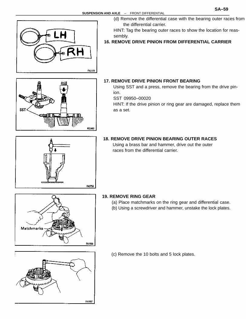
(d) Remove the differential case with the bearing outer races fromthe differential carrier.
HINT: Tag the bearing outer races to show the location for reas-sembly.
16. REMOVE DRIVE PINION FROM DIFFERENTIAL CARRIER
17. REMOVE DRIVE PINION FRONT BEARINGUsing SST and a press, remove the bearing from the drive pin-ion.SST 09950–00020HINT: If the drive pinion or ring gear are damaged, replace themas a set.
19. REMOVE RING GEAR(a) Place matchmarks on the ring gear and differential case.(b) Using a screwdriver and hammer, unstake the lock plates.
18. REMOVE DRIVE PINION BEARING OUTER RACESUsing a brass bar and hammer, drive out the outerraces from the differential carrier.
(c) Remove the 10 bolts and 5 lock plates.
–SUSPENSION AND AXLE FRONT DIFFERENTIALSA–59

20. REMOVE SIDE BEARINGSUsing SST, remove the side bearings from the differ-ential case.SST 09608 – 30012(09608 – 04060),09950–40010HINT: Fix the claws of SST to the notch in the differen-tial case.
(b) Remove these parts:(1) Pinion shaft(2) Pinion gears(3) Pinion gear thrust washers(4) Side gears(5) Side gear thrust washers
21. DISASSEMBLE DIFFERENTIAL CASE ASSEMBLY(a) Using a pin punch and hammer, drive out the straight pin.
(d) Using a plastic–faced hammer, tap on the ring gear toseparate it from the differential case.
(c) Using a brass bar and hammer, drive out the needlebearings.
–SUSPENSION AND AXLE FRONT DIFFERENTIALSA–60

SIDE GEAR SHAFT INSPECTION ANDREPLACEMENT1. INSPECT CLUTCH HUB AND CLUTCH SLEEVE
(a) Check the wear and damage of the clutch hub andclutch sleeve.
If necessary, replace them.(b) Check that clutch sleeve slides smoothly on the clutch
hub.
2. REMOVE CLUTCH HUB(a) Using a snap ring expander, remove the snap ring.(b) Remove the clutch hub from the side gear shaft.
3. REMOVE SIDE GEAR SHAFT FROM TUBE(a) Remove the 3 bearing retainer bolts.(b) Remove the side gear shaft from the tube.
4. REPLACE SIDE GEAR SHAFT BEARING(a) Using a snap ring expander, remove the snap ring.
(b) Using SST and a press, remove the bearing.SST 09950–00020
–SUSPENSION AND AXLE FRONT DIFFERENTIALSA–61

(c) Using SST, press in the oil seal.SST 09554–14010
Oil seal press in depth:2.5 mm (0.098 in. )
(d) Coat the lip of oil seal with MP grease.
(b) With the oil seal lip facing upward, use press and plateto press in a new oil seal until its end is flush with thesurface of the tube.
6. REPLACE SIDE OIL SEAL(a) Using SST, remove the side oil seal.
SST 09308–00010
(d) Using SST and a press, install the bearing.SST 09316–60010 (09316–00040)
(c) Remove the bearing retainer.
–SUSPENSION AND AXLE FRONT DIFFERENTIALSA–62

6. INSTALL SIDE GEAR SHAFT(a) Install the side gear shaft into the tube.(b) Torque the 3 bearing retainer bolts.Torque: 12 N–m (120 kgf–cm, 9 ft–lbf)
7. INSTALL CLUTCH HUB(a) Install the clutch hub to the shaft.
(b) Using a snap ring expander, install the snap ring.
–SUSPENSION AND AXLE FRONT DIFFERENTIALSA–63

A.D.D. ACTUATOR INSPECTION ANDREPLACEMENT1. MEASURE CLEARANCE OF SLEEVE FORK AND
CLUTCH SLEEVEUsing a feeler gauge, measure the clearance betweenthe sleeve fork and clutch sleeve.Maximum clearance:
0.35 mm (0.0138 in.)If the clearance exceeds the maximum, replace the fork orsleeve.
2. INSPECT A.D.D. ACTUATOR(a) Check that the sleeve fork moves to the actuator side
when a vacuum of 500 mmHg (19.69 in.Hg, 66.7 kPa)is applied to port A. Also check that the vacuumremains constant.If it dose not, replace the actuator.
(b) Check that the sleeve fork moves away from theactuator when a vacuum of 500 mmHg (19.69 in.Hg,66.7 kPa) is applied to port B. Also check that thevacuum remains constant.If it dose not, replace the actuator.
4. REMOVE SLEEVE FORK PIN(a) Using a hexagon wrench, remove the screw plug.
3. REMOVE A.D.D. INDICATOR SWITCH
–SUSPENSION AND AXLE FRONT DIFFERENTIALSA–64

6. INSTALL SLEEVE FORK AND ACTUATOR INTOCLUTCH CASE COVER(a) Install a new O–ring to the actuator.(b) Coat the O–ring with MP grease.(c) Place the sleeve fork and install the actuator to the
clutch case cover.
(b) Separate the actuator from clutch case cover andremove the sleeve fork.
(c) Remove the O–ring from the actuator.
5. SEPARATE ACTUATOR FROM CLUTCH CASECOVER AND REMOVE SLEEVE FORK(a) Remove the 2 bolts.
(b) Using a pin punch and hammer, drive out the pinthrough the hole of clutch case cover.
(d) Torque the 2 bolts.Torque: 21 N–m (210 kgf–cm, 15 ft–lbf)
–SUSPENSION AND AXLE FRONT DIFFERENTIALSA–65

(b) Coat the threads of screw plug with FIPG.FIPG:
Part No. 08826–00090, THREE BOND 1281 orequivalent
(c) Using a hexagon wrench, install the screw plug.Torque: 20 N–m (200 kgf–cm, 14 ft–lbf)
7. INSTALL SLEEVE FORK PIN(a) Using a pin punch and hammer, drive in the pin
through the hole of clutch case cover.
8. INSTALL A.D.D. INDICATOR SWITCHInstall a new gasket and indicator switch.Torque: 40 N–m (410 kgf–cm, 30 ft–lbf)
–SUSPENSION AND AXLE FRONT DIFFERENTIALSA–66

DIFFERENTIAL CARRIER ASSEMBLY1. ASSEMBLE DIFFERENTIAL CASE
(a) Using SST and a press, press in a new needle bearing.NOTICE: Press in the bearings, with the engraved side of eachbearing facing outward from the differential case.
SST 09620–30010 (09625 –30010)
(d) Measure the side gear backlash while holding 1 pin-ion gear toward the differential case.
Backlash:0.05 – 0.20 mm (0.0020 – 0.0079 in.)
If the backlash is not within the specification, installside gear thrust washers with different thicknesses.
(b) Install the proper thrust washers on the side gears.HINT: Using the table below, select thrust washers whichwill ensure that the backlash is within specifications.Washer thickness
(c) Install the side gears, pinion gears, pinion gear thrustwashers and pinion shaft in the differential case.
HINT: Align the holes of the differential case and pin-ion shaft.
Bearing press in depth:2.0 mm (0.079 in.)
Thickness mm (in.) Thickness mm (in.)
–SUSPENSION AND AXLE FRONT DIFFERENTIALSA–67

3. INSTALL RING GEAR ON DIFFERENTIAL CASE(a) Clean the contact surfaces of the differential case and ring
gear.(b) Heat the ring gear to about 100°C (212°F) in boiling water.(c) Carefully remove the ring gear from the water.(d) After the moisture on the ring gear has completely evaporated,
quickly install the ring gear to the differential case.
HINT: Align the matchmarks on the ring gear and dif-ferential case.(e) Temporarily install 5 new lock plates and 10 bolts sc
that the bolt holes in the ring gear and differentialcase are not misaligned.
(f) After the ring gear has cooled sufficiently, torque thering gear set bolts.
Torque: 97 N–m (985 kgf–cm. 71 ft–lbf)
(g) Using a hammer and drift punch, stake the lockplates
HINT: Stake 1 claw flush with the flat surface of thenut. For the claw contacting the protruding portion o –the nut, stake only the half portion of the tighteningside.
2. INSTALL STRAIGHT PIN AND STAKE DIFFERENTIAL CASE(a) Using a pin punch and hammer, install the straight pin through
the differential case and hole of the pinion shaft.
(b) Stake the differential case.
–SUSPENSION AND AXLE FRONT DIFFERENTIALSA–68

7. INSTALL DRIVE PINION FRONT BEARING(a) Install the washer on the drive pinion.HINT: First fit a washer with the same thickness as the washerwhich was removed, then after checking the tooth contact pat-tern, replace the washer with one of a different thickness if nec-essary.(b) Using SST, press in the front bearing onto the drive pinion.
SST 09506–30012
6. CHECK RING GEAR RUNOUT(a) Install the differential case onto the carrier and install
the plate washers to where there is no play in thebearing. (See page SA–70)
(b) Install bearing caps. (See page SA–73)(c) Using a dial indicator, measure the runout of ring gear.Maximum runout:
0.07 mm (0.0028 in.)
6. INSTALL DRIVE PINION FRONT AND REAR BEARING OUTERRACESUsing SST and a press, install new outer races.Front:SST 09608–35014 (09608–06020, 09608–06120)Rear:SST 09608 – 35014 (09608 – 06020, 09608 – 04110)
8. TEMPORARILY ADJUST DRIVE PINION PRELOAD(a) Install the drive pinion, rear bearing and oil slinger.HINT: Assemble the spacer and oil seal after adjustingthe gear contact pattern.
4. INSTALL SIDE BEARINGSUsing SST and a press, press the bearing into the differential
case.SST 09226–10010, 09550–10012 (09558– 10010)
–SUSPENSION AND AXLE FRONT DIFFERENTIALSA–69

9. INSTALL DIFFERENTIAL CASE IN DIFFERENTIALCARRIER(a) Place the bearing outer races on their respective bearings.
Check that the left and right outer races are not interchanged.(b) Install the differential case in the differential carrier.
(d) Adjust the drive pinion preload by tightening the com-panion flange nut.
(e) Using SST to hold the flange, tighten the nut.SST 09330 – 00021
NOTICE: As there is no spacer, tighten the nut a little at atime, being careful not to overtighten it.
(f) Using a torque wrench, measure the preload.New bearing preload (at starting):
1.2 – 1.9 N–m (12 – 19 kgf–cm, 10.4 – 16.5 in.–lbf)Reused bearing preload (at starting):
0.6 – 1.0 N–m (6 – 10 kgf–cm, 5.2 – 8.7 in.–lbf)
10. ADJUST RING GEAR BACKLASH(a) Only install the plate washer on the ring gear back
side.HINT: Ensure that the ring gear has backlash.
(b) Using SST, install the companion flange.SST 09950 – 30010(c) Coat the threads of the nut with MP grease.
–SUSPENSION AND AXLE FRONT DIFFERENTIALSA–70

(e) Select a ring gear teeth side plate washer with a thick-ness which eliminates any clearance between theouter race and case.
(c) Hold the side bearing boss on the teeth surface of thering gear and measure the backlash.
Backlash (reference):0.13 mm (0.0051 in.)
(f) Remove the plate washes and differential case.(g) Install the plate washer into the ring gear back side of
the carrier.
(d) Select a ring gear back side plate washer, using thebacklash as reference. (See page SA–73)
(b) Tap on the ring gear with a plastic–faced hammer sothat the washer fit to bearing.
–SUSPENSION AND AXLE FRONT DIFFERENTIALSA–71
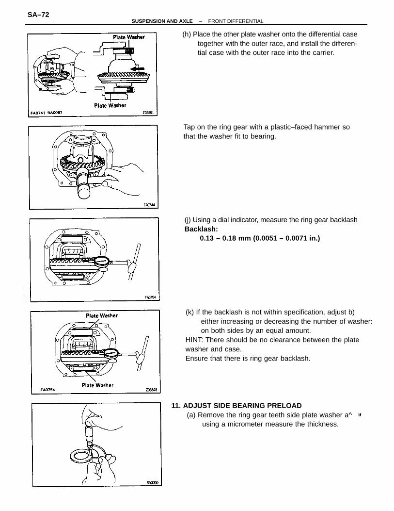
(k) If the backlash is not within specification, adjust b)either increasing or decreasing the number of washer:on both sides by an equal amount.
HINT: There should be no clearance between the platewasher and case.Ensure that there is ring gear backlash.
(j) Using a dial indicator, measure the ring gear backlashBacklash:
0.13 – 0.18 mm (0.0051 – 0.0071 in.)
(h) Place the other plate washer onto the differential casetogether with the outer race, and install the differen-tial case with the outer race into the carrier.
11. ADJUST SIDE BEARING PRELOAD(a) Remove the ring gear teeth side plate washer a^
using a micrometer measure the thickness.
Tap on the ring gear with a plastic–faced hammer sothat the washer fit to bearing.
–SUSPENSION AND AXLE FRONT DIFFERENTIALSA–72

(d) Recheck the ring gear backlash.Backlash:
0.13 – 0.18 mm (0.0051 – 0.0071 in.)(e) If the backlash is not within specification, adjust by
either increasing or decreasing the washers on bothsides by an equal amount.HINT: The backlash will change about 0.02 mm(0.0008 in.) with 0.03 mm (0.0012 in.) alteration of theplate washer.Washer thickness
(b) Using the backlash as a reference, install a new washer of0.06 – 0.09 mm (0.0024 – 0.0035 in.)thicker than the washer removed.
HINT: Select a washer which can be pressed in 2/3 of theway with your finger.(c) Using a plastic – faced hammer, tap in the plate washer.
13. MEASURE TOTAL PRELOADUsing a torque wrench, measure the total preload.Total preload (at starting) :Add drive pinion preload0.4 – 0.6 N–m (4 – 6 kgf–cm, 3.5 – 5.2 in.–lbf)
12. INSTALL BEARING CAPSAlign the matchmarks on the cap and carrier.Torque: 78 N–n (800 kgf–cm, 58 ft–lbf)
Thickness mm (in.)Thickness mm (in.)
–SUSPENSION AND AXLE FRONT DIFFERENTIALSA–73

14. INSPECT TOOTH CONTACT BETWEEN RING GEARAND DRIVE PINION(a) Coat 3 or 4 teeth at 3 different positions on the ring
gear with red lead.(b) Hold the companion flange firmly and rotate the ring
gear in both directions.(c) Inspect the tooth pattern.
If the teeth are not contacting properly, use the followingchart to select a proper washer for correction.Washer thickness
Thickness mm (in.)Thickness mm (in.)
–SUSPENSION AND AXLE FRONT DIFFERENTIALSA–74

18. CHECK DRIVE PINION PRELOADUsing a torque wrench, measure the drive pinion preloadusing the backlash of the drive pinion and ring gear.New bearing preload (at starting):
1.2 – 1.9 N–m (12 – 19 kgf–cm, 10.4 – 16.5 in.–lbf)Reused bearing preload (at starting):
0.6 – 1.0 N–m (6 – 10 kgf–cm, 5.2 – 8.7 in.–lbf)
(b) Install the plate washer.(c) Coat the threads of a new nut with MP grease and
install it.(d) Using SST to hold the flange, tighten the nut.
SST 09330–00021Torque: 120 N–m (1,225 kgf–cm, 89 ft–lbf
16. INSTALL BEARING SPACER(a) Remove the companion flange.
(See page SA–57)(b) Remove the oil slinger and rear bearing.
(See page SA–58)(c) Install a new bearing spacer.(d) Install the rear bearing and oil slinger.
16. INSTALL OIL SEAL(a) Using SST and a hammer, tap in a new oil seal.
SST 08554–30011Oil seal drive in depth:
1.5 mm (0.059 in.)(b) Apply MP grease to the oil seal lip.
.17. INSTALL COMPANION FLANGE(a) Using SST, install the companion flange.
SST 09950–30010
–SUSPENSION AND AXLE FRONT DIFFERENTIALSA–75

If the preload is greater than the specification, replace thespacer.If the preload is less than the specification, retighten thenut a little at a time with a torque of 13N–m (130 kgf–cm, 9 ft–lbf) until the specified preload isreached.Maximum torque:
223 N–m (2,275 kgf–cm, 165 ft–lbf)If the maximum torque is exceeded while retightening thenut, replace the spacer and repeat the preload procedure.Do not back off the nut to reduce the preload.
21. CHECK RUNOUT OF COMPANION FLANGEUsing a dial indicator, measure the vertical and lateralrunout of the companion flange.Maximum vertical runout:
0.10 mm (0.0039 in.)
20. RECHECK TOOTH CONTACT BETWEEN RINGGEAR AND DRIVE PINION(See page SA–74)
19. RECHECK RING GEAR BACKLASH(See page SA–73)
–SUSPENSION AND AXLE FRONT DIFFERENTIALSA–76

24. INSTALL RH SIDE GEAR SHAFT(a) Install a new snap ring to the side gear shaft.(b) Using a plastic–faced hammer, tap in the side gear shaft
to the differential case.26. CHECK INSTALLATION OF SIDE GEAR SHAFT
(a) Check that there is 2 – 3 mm (0.08 – 0.12 in.) of playin axial direction.
(b) Check that the side gear shaft can not be pulled out byhand.
26. INSTALL INTERMEDIATE SHAFT(a) Install a new snap ring to the shaft.(b) Using a plastic–faced hammer, tap in the shaft to the dif-
ferential case.27: CHECK INSTALLATION OF INTERMEDIATE SHAFT
(a) Check that there is 2 – 3 mm (0.08 – 0.12 in.) of playin axial direction.
(b) Check that the intermediate shaft can not be pulled outby hand.
23. INSTALL RH SIDE GEAR SHAFT OIL SEAL(a) Using SST and a hammer, tap in a new oil seal until
its surface is flush with the differential carrier end.SST 09550–22011 (09550–00020, 09550–00031)
(b) Apply MP grease to the oil seal lip.
Maximum lateral runout:0.10 mm (0.0039 in.)
If the runout is greater than maximum, inspect thebearings.
22. STAKE DRIVE PINION NUT
–SUSPENSION AND AXLE FRONT DIFFERENTIALSA–77

30. INSTALL LH SIDE GEAR SHAFT TO DIFFERENTIALCARRIER(a) Remove any old FIPG material and be careful not to
drop oil on the contact surfaces of the differentialcarrier and clutch case.
(b) Clean contact surfaces of any residua) FIPG materialusing gasoline or alcohol.
(c) Apply FIPG to the carrier, as shown.FIPG:
Part No. 08826–00090, THREE BOND 1281 orequivalent
HINT: Install the side gear shaft within ten minutesafter applying FIPG.(d) Install LH side gear shaft to the differential carrier.(e) Torque the 4 torx bolts.
Torx socket E14 (Part No.09044–00010 or locallymanufactured tool)
Torque: 78 N–m (800 kgf–cm, 58 ft–lbf)
(c) Install the clutch case to the tube.(d) Torque the 2 torx bolts.
Torx socket E14 (Part No.09044–00010 or locallymanufactured tool)
Torque: 78 N–m (800 kgf–cm, 58 ft–lbf)
28. INSTALL CLUTCH CASE TO SIDE GEAR SHAFTTUBE(a) Install a new O–ring to the tube.(b) Coat the O–ring with MP grease.
29. INSTALL CLUTCH SLEEVE
–SUSPENSION AND AXLE FRONT DIFFERENTIALSA–78

31. INSTALL DIFFERENTIAL CARRIER COVER(a) Remove any old FIPG material and be careful not to
drop oil on the contact surfaces of the differential car-rier and carrier cover.
(b) Clean contacting surfaces of any residual FIPG mate-rial using gasoline or alcohol.
(c) Apply FIPG to the carrier cover, as shown.FIPG:
Part No. 08826–00090, THREE BOND 1281 orequivalent
FIPG width approx:1–2 mm (0.04–0.08 in.)
HINT: Install the carrier cover within 10 minutes afterapplying FIPG.(d) Install the differential carrier cover with the 8 bolts.Torque: 47 N–m (475 kgf–cm, 34 ft–lbf)
32. INSTALL A.D.D. ACTUATOR(a) Remove any old FIPG material and be careful not to
drop oil on the contact surfaces of the actuator andclutch case.
(b) Clean contact surfaces of any residual FIPG materialusing gasoline or alcohol.
(c) Apply FIPG to the clutch case, as shown.FIPG:
Part No. 08826–00090, THREE BOND 1281 orequivalent
HINT: Install the actuator within 10 minutes afterapplying FIPG.(d) Torque the 4 bolts.Torque: 21 N–m (210 kgf–cm, 15 ft–lbf)
–SUSPENSION AND AXLE FRONT DIFFERENTIALSA–79