Embed Size (px)
Citation preview

Safe and Fault Tolerant Controllers SIMATIC Safety Integrated for Process Automation Wiring and Evaluation Architectures for Failsafe Digital Input (F-DI)- and Output-Modules (F-DO) of ET 200M
Fun
ctio
na
l Ex
am
ple
No
AS-
FE-I
I-0
02
-V1
0-E
N
Wiring and Evaluation Architectures for F-DI/F-DO Entry ID: 37236961
I IA/DT Safety Integrated Page 2/93 AS-FE-II-002-V10-EN
Co
pyr
igh
t S
iem
en
s A
G 2
01
0 A
ll rig
hts
re
serv
ed
3
723
696
1_
Wiri
ng_
and
_V
otin
g_E
T2
00M
_F
DI_
FD
O_
en_
V1
0.d
oc
Preliminary Remarks
The functional examples dealing with “failsafe systems” are fully functional and tested automation configurations based on I IA/DT standard products for simple, fast and inexpensive implementation of automation tasks in safety engineering. Each of these Functional Examples covers a frequently occurring subtask of a typical customer problem in safety engineering.
Aside from a list of all required software and hardware components and a description of the way they are connected to each other, the Functional Examples include the tested and commented code. This ensures that the functionalities described here can be reset in a short period of time and thus also be used as a basis for individual expansions.
Important note
The Safety Functional Examples are not binding and do not claim to be complete regarding the circuits shown, equipping and any eventuality. The Safety Functional Examples do not represent customer-specific solutions. They are only intended to provide support for typical applications. You are responsible for ensuring that the described products are used correctly.
These Safety Functional Examples do not relieve you of the responsibility of safely and professionally using, installing, operating and servicing equipment. When using these Safety Functional Examples, you recognize that Siemens cannot be made liable for any damage/claims beyond the liability clause described. We reserve the right to make changes to these Safety Functional Examples at any time without prior notice. If there are any deviations between the recommendations provided in these Safety Function Examples and other Siemens publications – e.g. Catalogs – the contents of the other documents have priority.
Table of Contents
Wiring and Evaluation Architectures for F-DI/F-DO Entry ID: 37236961
I IA/DT Safety Integrated Page 3/93 AS-FE-II-002-V10-EN
Co
pyr
igh
t S
iem
en
s A
G 2
01
0 A
ll rig
hts
re
serv
ed
3
723
696
1_
Wiri
ng_
and
_V
otin
g_E
T2
00M
_F
DI_
FD
O_
en_
V1
0.d
oc
Table of Contents Warranty / Disclaimer of Liability ......................................................................... 5 1 Automation Function ............................................................................ 6 1.1 Functionality of the functional example................................................ 6 1.2 Introduced architectures....................................................................... 8 1.3 Properties of the failsafe digital input module ...................................... 9 1.4 Properties of the failsafe digital output modul .................................... 12 2 Setup and Wiring for one Sensor (1oo1)............................................ 14 2.1 Calculating the PFD ........................................................................... 15 2.2 Wiring ................................................................................................. 15 2.2.1 Conventional Wiring ........................................................................... 15 2.2.2 Wiring with a Marshalled Termination Assembly ............................... 16 2.3 Hardware configuration in STEP 7..................................................... 17 2.4 Configuring the logic........................................................................... 21 2.4.1 Configuration with Safety Matrix ........................................................ 21 2.4.2 Configuration with CFC ...................................................................... 23
Configuration without evaluation of the channel error (1oo1) ............ 23 Configuration with Signal Quality (1oo1D) ......................................... 24
2.5 One Sensor with Redundant I/O Modules.......................................... 25 2.5.1 Calculating the PFD ........................................................................... 26 2.5.2 Wiring ................................................................................................. 27 2.5.3 Hardware configuration in STEP 7..................................................... 28 2.5.4 Configuring the logic........................................................................... 30 3 Setup and Wiring for two Sensors (1oo2): Evaluation in the F-DI
Module................................................................................................ 31 3.1 Calculating the PFD ........................................................................... 32 3.2 Wiring ................................................................................................. 33 3.2.1 Conventional Wiring ........................................................................... 33 3.2.2 Wiring with a Marshalled Termination Assembly ............................... 34 3.3 Hardware configuration in STEP 7..................................................... 34 3.4 Logic Configuration ............................................................................ 38 3.4.1 Configuration with Safety Matrix ........................................................ 38 3.4.2 Configuration with CFC ...................................................................... 40
Configuration without Signal Quality (1oo2)....................................... 40 Configuration with Signal Quality (1oo2D) ......................................... 40
3.5 Two Sensors with Redundant I/O Modules........................................ 41 3.5.1 Calculating the PFD ........................................................................... 43 3.5.2 Wiring ................................................................................................. 44 3.5.3 Hardware configuration in STEP 7..................................................... 45 3.5.4 Logic Configuration ............................................................................ 48 4 Setup and Wiring for two Sensors (1oo2): Evaluation in the User
Program.............................................................................................. 49 4.1 Option 1:............................................................................................. 49 4.1.1 Calculating the PFD (option 1) ........................................................... 50 4.2 Option 2:............................................................................................. 51 4.2.1 Calculating the PFD (option 2) ........................................................... 52 4.3 Wiring ................................................................................................. 52 4.3.1 Conventional Wiring ........................................................................... 52 4.3.2 Wiring with a Marshalled Termination Assembly ............................... 53 4.4 Hardware configuration in STEP 7..................................................... 54 4.5 Logic Configuration ............................................................................ 57 4.5.1 Configuration with Safety Matrix ........................................................ 57
Table of Contents
Wiring and Evaluation Architectures for F-DI/F-DO Entry ID: 37236961
I IA/DT Safety Integrated Page 4/93 AS-FE-II-002-V10-EN
Co
pyr
igh
t S
iem
en
s A
G 2
01
0 A
ll rig
hts
re
serv
ed
3
723
696
1_
Wiri
ng_
and
_V
otin
g_E
T2
00M
_F
DI_
FD
O_
en_
V1
0.d
oc
4.5.2 Configuration with CFC ...................................................................... 58 Configuration without Signal Quality (1oo2)....................................... 58 Configuration with Signal Quality (1oo2D) ......................................... 59
4.6 Two Sensors with Redundant I/O Modules........................................ 61 4.6.1 Calculating the PFD ........................................................................... 62 4.6.2 Wiring ................................................................................................. 63 4.6.3 Hardware configuration in STEP 7..................................................... 64 4.6.4 Logic Configuration ............................................................................ 66 5 Setup and Wiring for final elements ................................................... 67 5.1.1 Calculating the PFD ........................................................................... 68 5.2 Wiring ................................................................................................. 68 5.2.1 Conventional Wiring ........................................................................... 68 5.2.2 Wiring with a Marshalled Termination Assembly ............................... 69 5.3 Hardware configuration in STEP 7..................................................... 69 5.4 Logic Configuration ............................................................................ 73 5.4.1 Configuration with Safety Matrix ........................................................ 73 5.4.2 Configuration with CFC ...................................................................... 74 5.5 Final Element Voting with Redundant I/O Modules ........................... 75 5.5.1 Calculating the PFD ........................................................................... 76 5.5.2 Wiring ................................................................................................. 77 5.5.3 Hardware configuration in STEP 7..................................................... 78 5.5.4 Logic Configuration ............................................................................ 80 Appendix............................................................................................................ 81 6 Calculating the PFD Value ................................................................. 81 7 Power and Grounding Recommendations ......................................... 82 7.1 Power ................................................................................................. 82 7.1.1 Power Feed Distribution..................................................................... 82 7.1.2 System Power Distribution ................................................................. 82 7.2 Grounding........................................................................................... 83 7.2.1 Objectives........................................................................................... 83 7.2.2 Implementation................................................................................... 83 8 F-DI Marshalled Termination Assemblies (MTAs) ............................. 86 9 F-DO Marshalled Termination Assemblies (MTAs) ........................... 89 10 Bibliography........................................................................................ 93 11 History ................................................................................................ 93

Warranty / Disclaimer of Liability
Wiring and Evaluation Architectures for F-DI/F-DO Entry ID: 37236961
I IA/DT Safety Integrated Page 5/93 AS-FE-II-002-V10-EN
Co
pyr
igh
t S
iem
en
s A
G 2
01
0 A
ll rig
hts
re
serv
ed
3
723
696
1_
Wiri
ng_
and
_V
otin
g_E
T2
00M
_F
DI_
FD
O_
en_
V1
0.d
oc
Warranty / Disclaimer of Liability We do not accept any liability for the information contained in this
document.
Any claims against us – based on whatever legal reason – resulting
from the use of the examples, information, programs, engineering and
performance data etc., described in this Safety Functional Example
shall be excluded. Such an exclusion shall not apply in the case of
mandatory liability, e.g. under the German Product Liability Act
(“Produkthaftungsgesetz”), in case of intent, gross negligence, or
injury of life, body or health, guarantee for the quality of a product,
fraudulent concealment of a deficiency or breach of a condition which
goes to the root of the contract (“wesentliche Vertragspflichten”). The
damages for a breach of a substantial contractual obligation are,
however, limited to the foreseeable damage, typical for the type of
contract, except in the event of intent or gross negligence or injury to
life, body or health. The above provisions do not imply a change of
the burden of proof to your detriment.
Copyright© 2010 Siemens I IA AS. Any form of duplication or
distribution of these Application Examples or excerpts hereof is
prohibited without the expressed consent of Siemens I IA AS.
Reference to SIEMENS Automation and Drives Service & Support
This article is taken from the Service Portal of Siemens AG, Industry
Automation and Drives Technologies. The following link takes you directly
to the download page of this document:
http://support.automation.siemens.com/WW/view/en/37236961
Automation Function
Wiring and Evaluation Architectures for F-DI/F-DO Entry ID: 37236961
I IA/DT Safety Integrated Page 6/93 AS-FE-II-002-V10-EN
Co
pyr
igh
t S
iem
en
s A
G 2
01
0 A
ll rig
hts
re
serv
ed
3
723
696
1_
Wiri
ng_
and
_V
otin
g_E
T2
00M
_F
DI_
FD
O_
en_
V1
0.d
oc
1 Automation Function
1.1 Functionality of the functional example
Task
Several digital signals shall be monitored failsafe in a plant. Depending on importance and failure risk, there are several options of wiring and evaluating the signals. Evaluation may, for example, occur in the digital input module and/or in the user program.
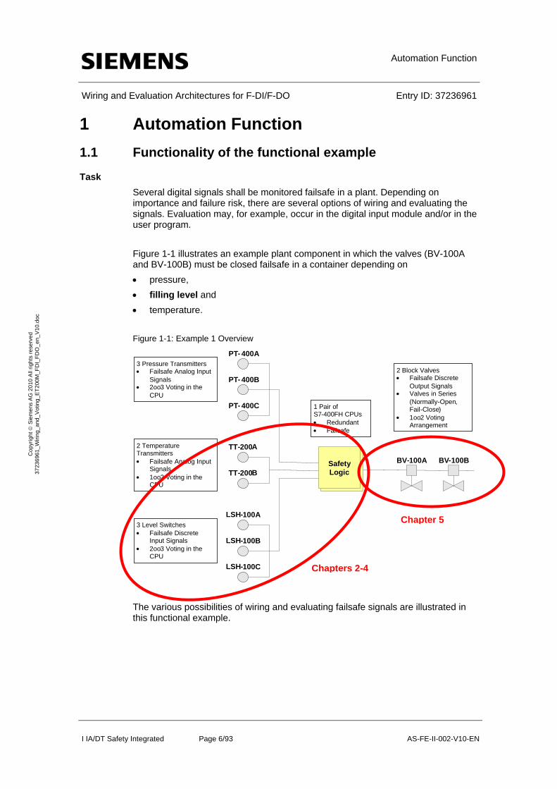
Figure 1-1 illustrates an example plant component in which the valves (BV-100A and BV-100B) must be closed failsafe in a container depending on
pressure,
filling level and
temperature.
Figure 1-1: Example 1 Overview
The various possibilities of wiring and evaluating failsafe signals are illustrated in this functional example.
PT- 400A
PT- 400B
PT- 400C
TT-200A
TT-200B
BV - 100A BV - 100B
3 Pressure Transmitters Failsafe Analog Input
Signals 2oo3 Voting in the
CPU
2 Temperature Transmitters Failsafe Analog Input
Signals 1oo2 Voting in the
CPU
LSH-100A
LSH-100B
LSH-100C
3 Level Switches Failsafe Discrete
Input Signals 2oo3 Voting in the
CPU
2 Block Valves Failsafe Discrete
Output Signals Valves in Series
( Normally - Open, Fail -Close)
1
oo
2
Voting
Arrangement
1
Pair of
S
7
-
400
FH CPUs
Redundant
Failsafe
Safety Logic
Chapters 2-4
Chapter 5
Automation Function
Wiring and Evaluation Architectures for F-DI/F-DO Entry ID: 37236961
I IA/DT Safety Integrated Page 7/93 AS-FE-II-002-V10-EN
Co
pyr
igh
t S
iem
en
s A
G 2
01
0 A
ll rig
hts
re
serv
ed
3
723
696
1_
Wiri
ng_
and
_V
otin
g_E
T2
00M
_F
DI_
FD
O_
en_
V1
0.d
oc
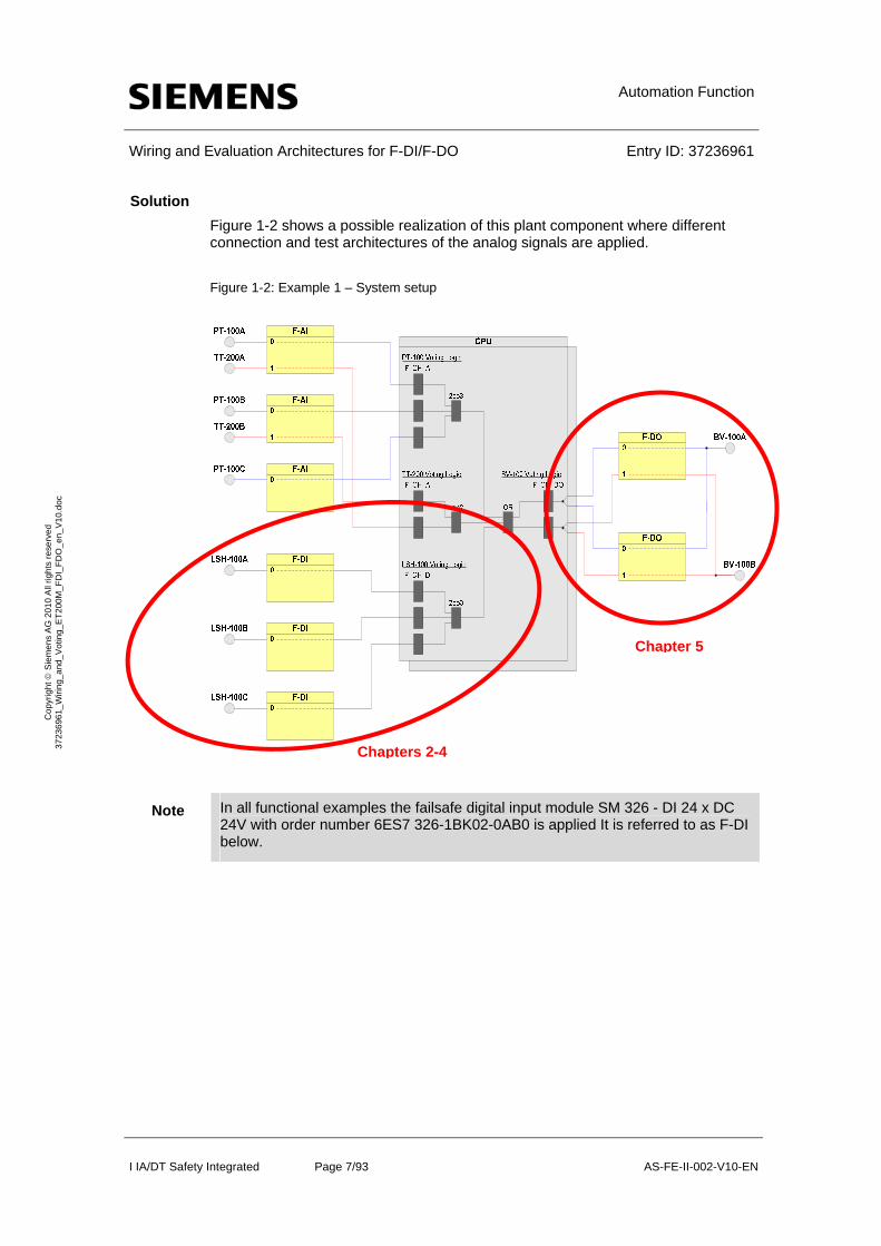
Solution
Figure 1-2 shows a possible realization of this plant component where different connection and test architectures of the analog signals are applied.
Figure 1-2: Example 1 – System setup
Note In all functional examples the failsafe digital input module SM 326 - DI 24 x DC 24V with order number 6ES7 326-1BK02-0AB0 is applied It is referred to as F-DI below.
Chapters 2-4
Chapter 5
Automation Function
Wiring and Evaluation Architectures for F-DI/F-DO Entry ID: 37236961
I IA/DT Safety Integrated Page 8/93 AS-FE-II-002-V10-EN
Co
pyr
igh
t S
iem
en
s A
G 2
01
0 A
ll rig
hts
re
serv
ed
3
723
696
1_
Wiri
ng_
and
_V
otin
g_E
T2
00M
_F
DI_
FD
O_
en_
V1
0.d
oc
1.2 Introduced architectures
Recommended architectures
In this functional example the following recommended architectures are introduced:
One sensor (1oo1) Typical application in the case where one individual sensor has the required Safety Integrated Level and where increased availability is not required (details in chapter 2).
Two sensors (1oo2) evaluation in the F-DI Module Typical application in the case where one individual sensor does not have the required Safety Integration Level and increased availability is not required (details in chapter 3).
Two sensors (1oo2) evaluation in the user program Typical application in the case where one individual sensor does not have the required Safety Integration Level and visibility of the data of both sensors is required (details in chapter 3). This architecture can also be configured as 2oo2 for increased availability if an individual sensor has the required Safety Integration Level (details in chapter 4 ).
Single Final Element (1oo1) evaluation From the perspective of the safety system, all final element voting schemes are combinations of 1oo1 outputs. Each final element should react in the manner commanded by the safety system logic (details in chapter 5 ).
Automation Function
Wiring and Evaluation Architectures for F-DI/F-DO Entry ID: 37236961
I IA/DT Safety Integrated Page 9/93 AS-FE-II-002-V10-EN
Co
pyr
igh
t S
iem
en
s A
G 2
01
0 A
ll rig
hts
re
serv
ed
3
723
696
1_
Wiri
ng_
and
_V
otin
g_E
T2
00M
_F
DI_
FD
O_
en_
V1
0.d
oc
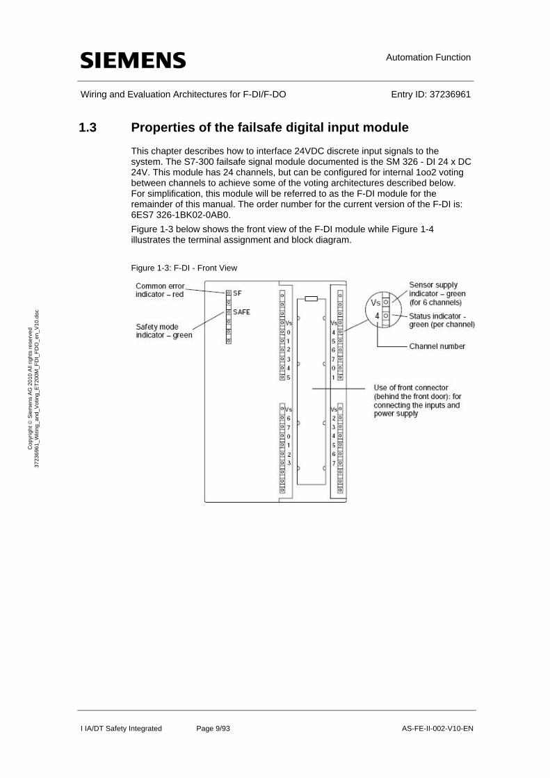
1.3 Properties of the failsafe digital input module
This chapter describes how to interface 24VDC discrete input signals to the system. The S7-300 failsafe signal module documented is the SM 326 - DI 24 x DC 24V. This module has 24 channels, but can be configured for internal 1oo2 voting between channels to achieve some of the voting architectures described below. For simplification, this module will be referred to as the F-DI module for the remainder of this manual. The order number for the current version of the F-DI is: 6ES7 326-1BK02-0AB0.
Figure 1-3 below shows the front view of the F-DI module while Figure 1-4 illustrates the terminal assignment and block diagram.
Figure 1-3: F-DI - Front View
Automation Function
Wiring and Evaluation Architectures for F-DI/F-DO Entry ID: 37236961
I IA/DT Safety Integrated Page 10/93 AS-FE-II-002-V10-EN
Co
pyr
igh
t S
iem
en
s A
G 2
01
0 A
ll rig
hts
re
serv
ed
3
723
696
1_
Wiri
ng_
and
_V
otin
g_E
T2
00M
_F
DI_
FD
O_
en_
V1
0.d
oc
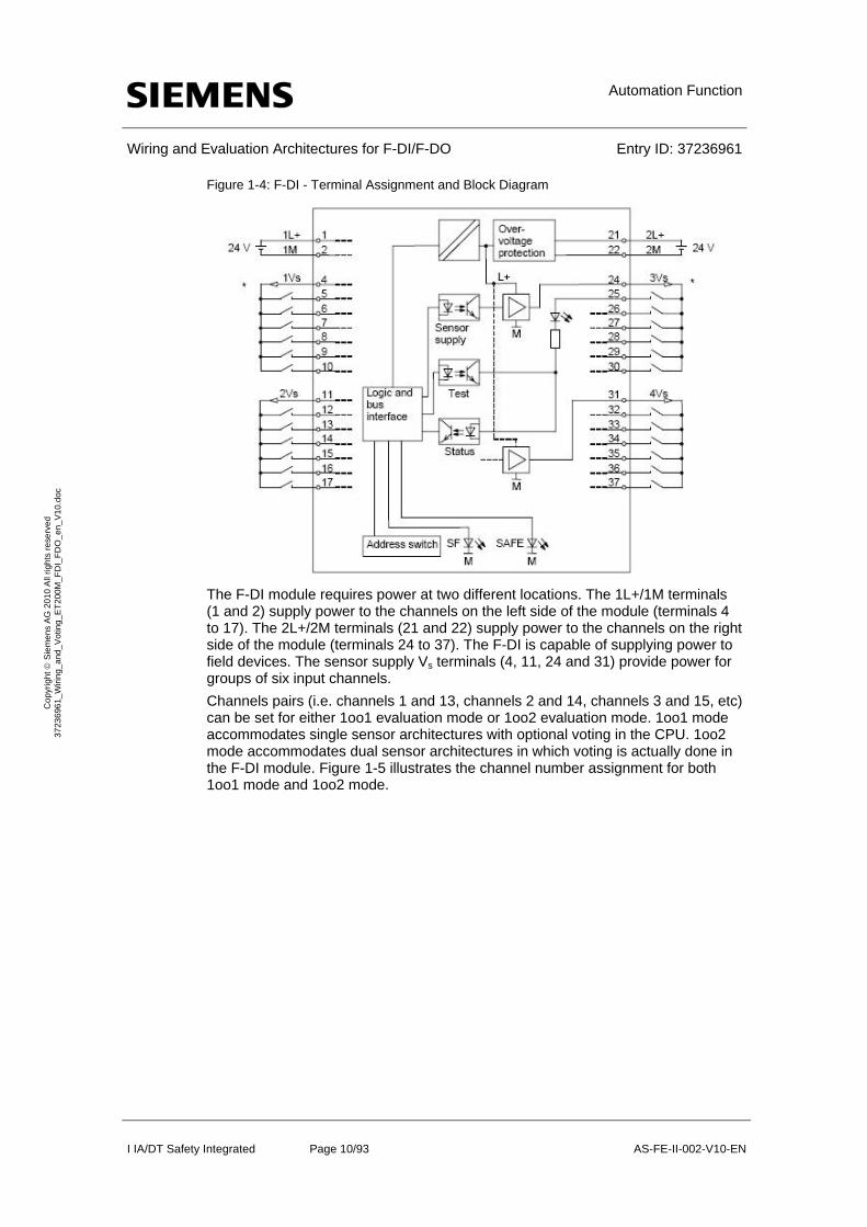
Figure 1-4: F-DI - Terminal Assignment and Block Diagram
The F-DI module requires power at two different locations. The 1L+/1M terminals (1 and 2) supply power to the channels on the left side of the module (terminals 4 to 17). The 2L+/2M terminals (21 and 22) supply power to the channels on the right side of the module (terminals 24 to 37). The F-DI is capable of supplying power to field devices. The sensor supply Vs terminals (4, 11, 24 and 31) provide power for groups of six input channels.
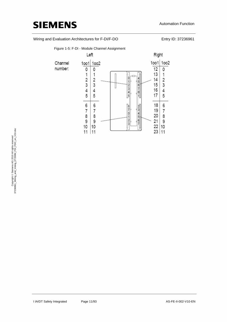
Channels pairs (i.e. channels 1 and 13, channels 2 and 14, channels 3 and 15, etc) can be set for either 1oo1 evaluation mode or 1oo2 evaluation mode. 1oo1 mode accommodates single sensor architectures with optional voting in the CPU. 1oo2 mode accommodates dual sensor architectures in which voting is actually done in the F-DI module. Figure 1-5 illustrates the channel number assignment for both 1oo1 mode and 1oo2 mode.
Automation Function
Wiring and Evaluation Architectures for F-DI/F-DO Entry ID: 37236961
I IA/DT Safety Integrated Page 11/93 AS-FE-II-002-V10-EN
Co
pyr
igh
t S
iem
en
s A
G 2
01
0 A
ll rig
hts
re
serv
ed
3
723
696
1_
Wiri
ng_
and
_V
otin
g_E
T2
00M
_F
DI_
FD
O_
en_
V1
0.d
oc
Figure 1-5: F-DI - Module Channel Assignment
Automation Function
Wiring and Evaluation Architectures for F-DI/F-DO Entry ID: 37236961
I IA/DT Safety Integrated Page 12/93 AS-FE-II-002-V10-EN
Co
pyr
igh
t S
iem
en
s A
G 2
01
0 A
ll rig
hts
re
serv
ed
3
723
696
1_
Wiri
ng_
and
_V
otin
g_E
T2
00M
_F
DI_
FD
O_
en_
V1
0.d
oc
1.4 Properties of the failsafe digital output modul
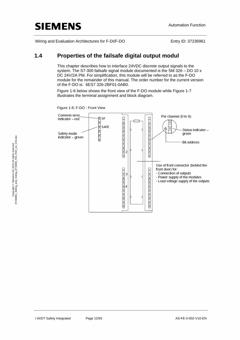
This chapter describes how to interface 24VDC discrete output signals to the system. The S7-300 failsafe signal module documented is the SM 326 – DO 10 x DC 24V/2A PM. For simplification, this module will be referred to as the F-DO module for the remainder of this manual. The order number for the current version of the F-DO is: 6ES7 326-2BF01-0AB0.
Figure 1-6 below shows the front view of the F-DO module while Figure 1-7 illustrates the terminal assignment and block diagram.
Figure 1-6: F-DO - Front View
Automation Function
Wiring and Evaluation Architectures for F-DI/F-DO Entry ID: 37236961
I IA/DT Safety Integrated Page 13/93 AS-FE-II-002-V10-EN
Co
pyr
igh
t S
iem
en
s A
G 2
01
0 A
ll rig
hts
re
serv
ed
3
723
696
1_
Wiri
ng_
and
_V
otin
g_E
T2
00M
_F
DI_
FD
O_
en_
V1
0.d
oc
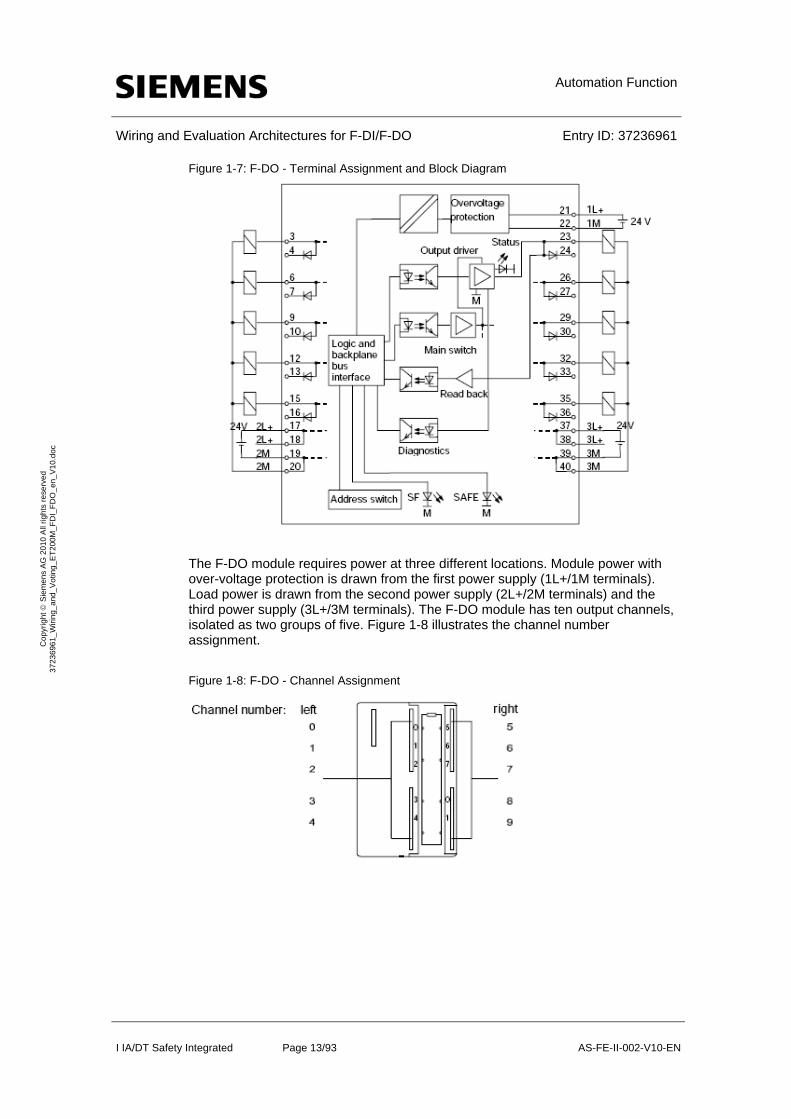
Figure 1-7: F-DO - Terminal Assignment and Block Diagram
The F-DO module requires power at three different locations. Module power with over-voltage protection is drawn from the first power supply (1L+/1M terminals). Load power is drawn from the second power supply (2L+/2M terminals) and the third power supply (3L+/3M terminals). The F-DO module has ten output channels, isolated as two groups of five. Figure 1-8 illustrates the channel number assignment.
Figure 1-8: F-DO - Channel Assignment
Setup and Wiring for one Sensor (1oo1)
Wiring and Evaluation Architectures for F-DI/F-DO Entry ID: 37236961
I IA/DT Safety Integrated Page 14/93 AS-FE-II-002-V10-EN
Co
pyr
igh
t S
iem
en
s A
G 2
01
0 A
ll rig
hts
re
serv
ed
3
723
696
1_
Wiri
ng_
and
_V
otin
g_E
T2
00M
_F
DI_
FD
O_
en_
V1
0.d
oc
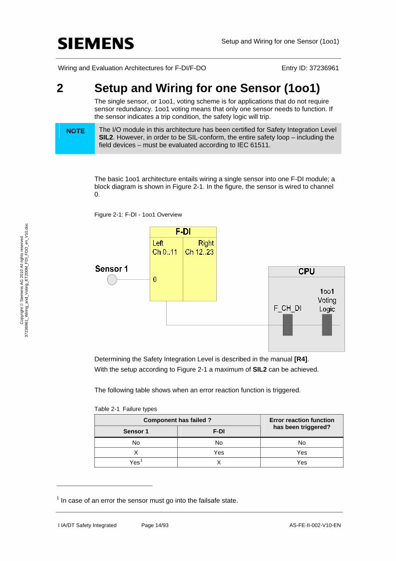
2 Setup and Wiring for one Sensor (1oo1) The single sensor, or 1oo1, voting scheme is for applications that do not require sensor redundancy. 1oo1 voting means that only one sensor needs to function. If the sensor indicates a trip condition, the safety logic will trip.
NOTE The I/O module in this architecture has been certified for Safety Integration Level SIL2. However, in order to be SIL-conform, the entire safety loop – including the field devices – must be evaluated according to IEC 61511.
The basic 1oo1 architecture entails wiring a single sensor into one F-DI module; a block diagram is shown in Figure 2-1. In the figure, the sensor is wired to channel 0.
Figure 2-1: F-DI - 1oo1 Overview
Determining the Safety Integration Level is described in the manual [R4].
With the setup according to Figure 2-1 a maximum of SIL2 can be achieved.
The following table shows when an error reaction function is triggered.
Table 2-1 Failure types
Component has failed ?
Sensor 1 F-DI
Error reaction function has been triggered?
No No No
X Yes Yes
Yes1 X Yes
1 In case of an error the sensor must go into the failsafe state.

Setup and Wiring for one Sensor (1oo1)
Wiring and Evaluation Architectures for F-DI/F-DO Entry ID: 37236961
I IA/DT Safety Integrated Page 15/93 AS-FE-II-002-V10-EN
Co
pyr
igh
t S
iem
en
s A
G 2
01
0 A
ll rig
hts
re
serv
ed
3
723
696
1_
Wiri
ng_
and
_V
otin
g_E
T2
00M
_F
DI_
FD
O_
en_
V1
0.d
oc
If the sensor or the F-DI fails, the error reaction function provides the safety function (through the failsafe system).
2.1 Calculating the PFD
The PFD value (Probability of Failure on Demand) describes the failure probability of the safety function.
PFD calculation formula
The PFD value for this wiring and evaluation architecture is calculated using the formula below:
PFD(1oo1) = PFDSensor + PFDFDI + PFDCPU
The PFDF-DI and PFDCPU values can be found in Chapter 6.
For a 1oo1 Sensor the PFDSensor is calculated by this formula2:
2.2 Wiring
2.2.1 Conventional Wiring
In the 1oo1 voting scheme, the F-DI module can provide power to the sensor or an external supply can be used.
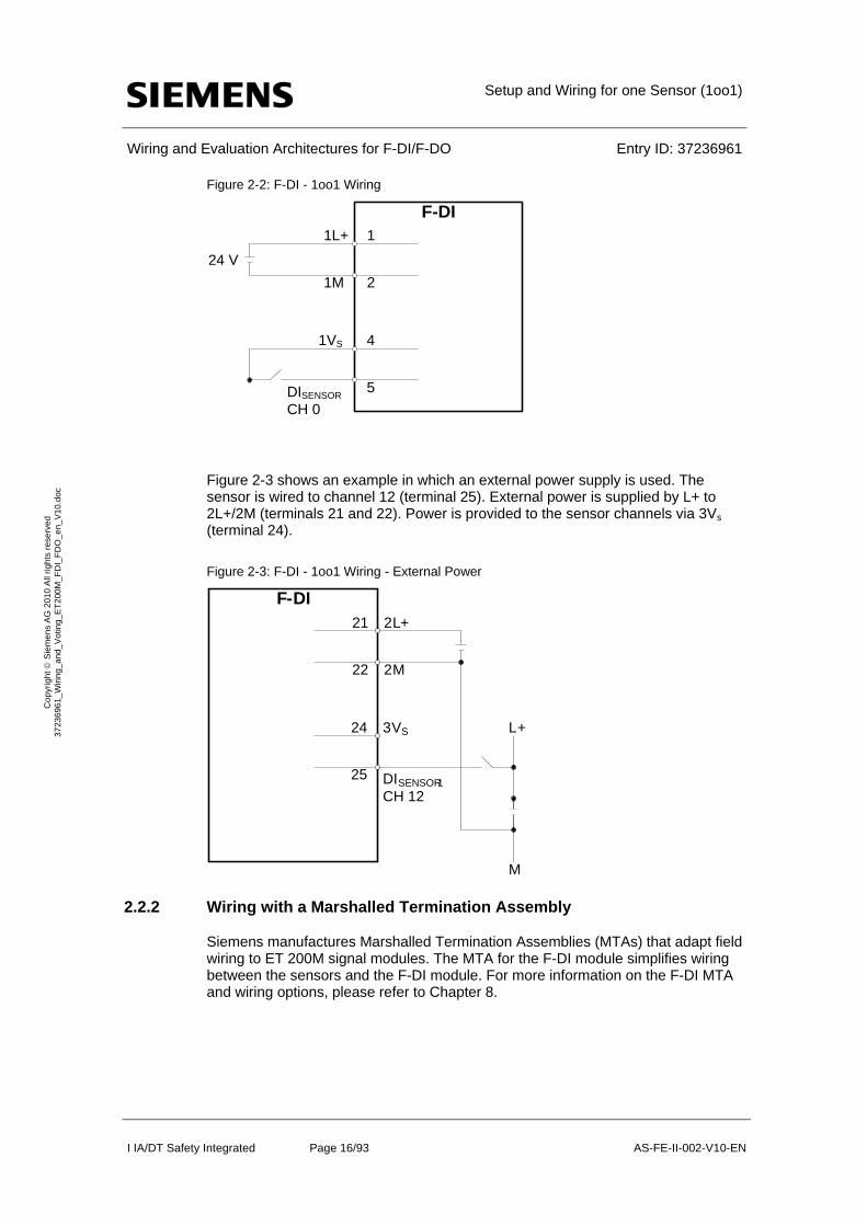
Figure 2-2 illustrates an example in which the F-DI module supplies power to the sensor wired to it. The sensor is wired to channel 0 (terminal 5). Power is drawn from 1L+/1M (terminals 1 and 2) and is provided to the sensor channel via 1Vs (terminal 4).
2 The formula is taken out of IEC61508, IEC 61511 and VDI 2180 Sheet 4
1 1 2 I
oo DU
TPFD
Setup and Wiring for one Sensor (1oo1)
Wiring and Evaluation Architectures for F-DI/F-DO Entry ID: 37236961
I IA/DT Safety Integrated Page 16/93 AS-FE-II-002-V10-EN
Co
pyr
igh
t S
iem
en
s A
G 2
01
0 A
ll rig
hts
re
serv
ed
3
723
696
1_
Wiri
ng_
and
_V
otin
g_E
T2
00M
_F
DI_
FD
O_
en_
V1
0.d
oc
Figure 2-2: F-DI - 1oo1 Wiring
F-DI1L+
1M
1
2
1VS
DISENSOR
CH 0
4
5
24 V
Figure 2-3 shows an example in which an external power supply is used. The sensor is wired to channel 12 (terminal 25). External power is supplied by L+ to 2L+/2M (terminals 21 and 22). Power is provided to the sensor channels via 3Vs (terminal 24).
Figure 2-3: F-DI - 1oo1 Wiring - External Power
2.2.2 Wiring with a Marshalled Termination Assembly
Siemens manufactures Marshalled Termination Assemblies (MTAs) that adapt field wiring to ET 200M signal modules. The MTA for the F-DI module simplifies wiring between the sensors and the F-DI module. For more information on the F-DI MTA and wiring options, please refer to Chapter 8.
F -DI 2L+
2M
21
22
3VS
DISENSOR1
CH 12
24
25
L+
M
Setup and Wiring for one Sensor (1oo1)
Wiring and Evaluation Architectures for F-DI/F-DO Entry ID: 37236961
I IA/DT Safety Integrated Page 17/93 AS-FE-II-002-V10-EN
Co
pyr
igh
t S
iem
en
s A
G 2
01
0 A
ll rig
hts
re
serv
ed
3
723
696
1_
Wiri
ng_
and
_V
otin
g_E
T2
00M
_F
DI_
FD
O_
en_
V1
0.d
oc
2.3 Hardware configuration in STEP 7
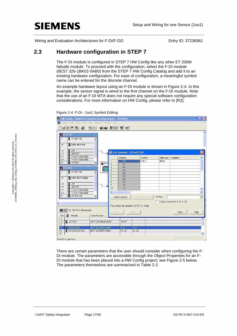
The F-DI module is configured in STEP 7 HW Config like any other ET 200M failsafe module. To proceed with the configuration, select the F-DI module (6ES7 326-1BK02-0AB0) from the STEP 7 HW Config Catalog and add it to an existing hardware configuration. For ease of configuration, a meaningful symbol name can be entered for the discrete channel.
An example hardware layout using an F-DI module is shown in Figure 2-4. In this example, the sensor signal is wired to the first channel on the F-DI module. Note that the use of an F-DI MTA does not require any special software configuration considerations. For more information on HW Config, please refer to [R2].
Figure 2-4: F-DI - 1oo1 Symbol Editing
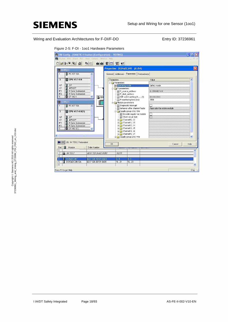
There are certain parameters that the user should consider when configuring the F-DI module. The parameters are accessible through the Object Properties for an F-DI module that has been placed into a HW Config project; see Figure 2-5 below. The parameters themselves are summarized in Table 2-2.
Setup and Wiring for one Sensor (1oo1)
Wiring and Evaluation Architectures for F-DI/F-DO Entry ID: 37236961
I IA/DT Safety Integrated Page 18/93 AS-FE-II-002-V10-EN
Co
pyr
igh
t S
iem
en
s A
G 2
01
0 A
ll rig
hts
re
serv
ed
3
723
696
1_
Wiri
ng_
and
_V
otin
g_E
T2
00M
_F
DI_
FD
O_
en_
V1
0.d
oc
Figure 2-5: F-DI - 1oo1 Hardware Parameters
Setup and Wiring for one Sensor (1oo1)
Wiring and Evaluation Architectures for F-DI/F-DO Entry ID: 37236961
I IA/DT Safety Integrated Page 19/93 AS-FE-II-002-V10-EN
Co
pyr
igh
t S
iem
en
s A
G 2
01
0 A
ll rig
hts
re
serv
ed
3
723
696
1_
Wiri
ng_
and
_V
otin
g_E
T2
00M
_F
DI_
FD
O_
en_
V1
0.d
oc
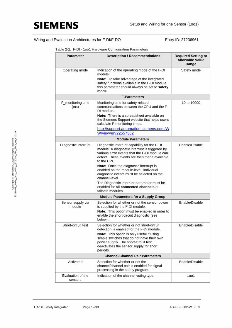
Table 2-2: F-DI - 1oo1 Hardware Configuration Parameters
Parameter Description / Recommendations Required Setting or Allowable Value
Range
Operating mode Indication of the operating mode of the F-DI module. Note: To take advantage of the integrated safety functions available in the F-DI module, this parameter should always be set to safety mode.
Safety mode
F-Parameters
F_monitoring time (ms)
Monitoring time for safety-related communications between the CPU and the F-DI module. Note: There is a spreadsheet available on the Siemens Support website that helps users calculate F-monitoring times.
http://support.automation.siemens.com/WW/view/en/22557362
10 to 10000
Module Parameters
Diagnostic interrupt Diagnostic interrupt capability for the F-DI module. A diagnostic interrupt is triggered by various error events that the F-DI module can detect. These events are then made available to the CPU. Note: Once the diagnostic interrupt is enabled on the module-level, individual diagnostic events must be selected on the channel-level. The Diagnostic interrupt parameter must be enabled for all connected channels of failsafe modules.
Enable/Disable
Module Parameters for a Supply Group
Sensor supply via module
Selection for whether or not the sensor power is supplied by the F-DI module. Note: This option must be enabled in order to enable the short-circuit diagnostic (see below).
Enable/Disable
Short-circuit test Selection for whether or not short-circuit detection is enabled for the F-DI module. Note: This option is only useful if using simple switches that do not have their own power supply. The short-circuit test deactivates the sensor supply for short periods.
Enable/Disable
Channel/Channel Pair Parameters
Activated Selection for whether or not the channel/channel pair is enabled for signal processing in the safety program.
Enable/Disable
Evaluation of the sensors
Indication of the channel voting type. 1oo1
Setup and Wiring for one Sensor (1oo1)
Wiring and Evaluation Architectures for F-DI/F-DO Entry ID: 37236961
I IA/DT Safety Integrated Page 20/93 AS-FE-II-002-V10-EN
Co
pyr
igh
t S
iem
en
s A
G 2
01
0 A
ll rig
hts
re
serv
ed
3
723
696
1_
Wiri
ng_
and
_V
otin
g_E
T2
00M
_F
DI_
FD
O_
en_
V1
0.d
oc
Parameter Description / Recommendations Required Setting or Allowable Value
Range
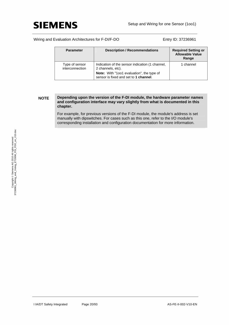
Type of sensor interconnection
Indication of the sensor indication (1 channel, 2 channels, etc). Note: With "1oo1 evaluation", the type of sensor is fixed and set to 1 channel.
1 channel
NOTE Depending upon the version of the F-DI module, the hardware parameter names and configuration interface may vary slightly from what is documented in this chapter.
For example, for previous versions of the F-DI module, the module's address is set manually with dipswitches. For cases such as this one, refer to the I/O module's corresponding installation and configuration documentation for more information.
Setup and Wiring for one Sensor (1oo1)
Wiring and Evaluation Architectures for F-DI/F-DO Entry ID: 37236961
I IA/DT Safety Integrated Page 21/93 AS-FE-II-002-V10-EN
Co
pyr
igh
t S
iem
en
s A
G 2
01
0 A
ll rig
hts
re
serv
ed
3
723
696
1_
Wiri
ng_
and
_V
otin
g_E
T2
00M
_F
DI_
FD
O_
en_
V1
0.d
oc
2.4 Configuring the logic
2.4.1 Configuration with Safety Matrix
After the sensor is added to the hardware configuration, the logic to monitor the sensor can be implemented in the CPU. One method is to use the SIMATIC Safety Matrix engineering tool (please refer to [R3]).
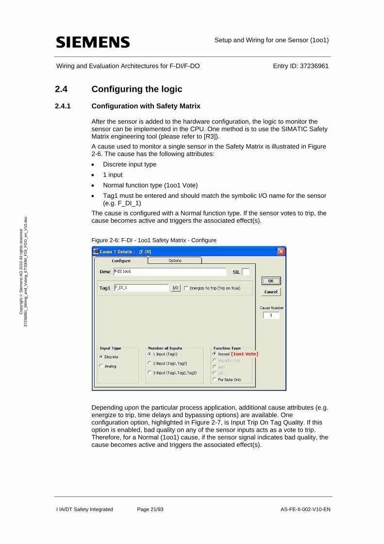
A cause used to monitor a single sensor in the Safety Matrix is illustrated in Figure 2-6. The cause has the following attributes:
Discrete input type
1 input
Normal function type (1oo1 Vote)
Tag1 must be entered and should match the symbolic I/O name for the sensor (e.g. F_DI_1)
The cause is configured with a Normal function type. If the sensor votes to trip, the cause becomes active and triggers the associated effect(s).
Figure 2-6: F-DI - 1oo1 Safety Matrix - Configure
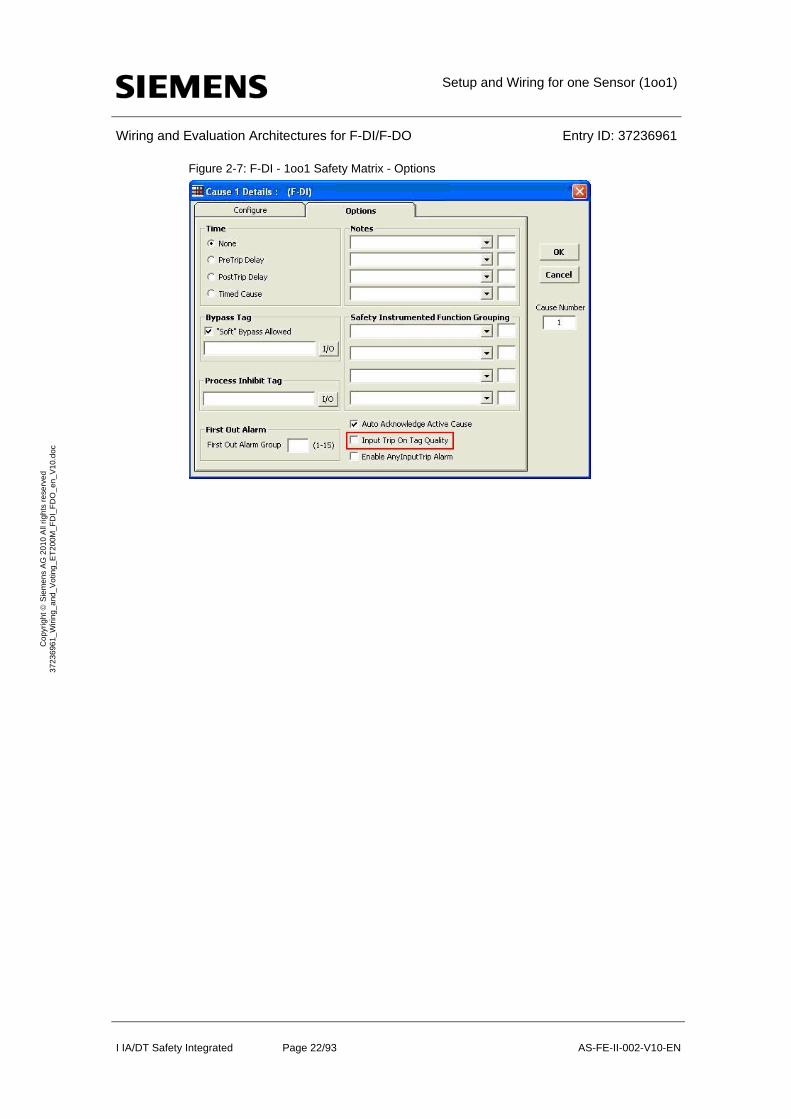
Depending upon the particular process application, additional cause attributes (e.g. energize to trip, time delays and bypassing options) are available. One configuration option, highlighted in Figure 2-7, is Input Trip On Tag Quality. If this option is enabled, bad quality on any of the sensor inputs acts as a vote to trip. Therefore, for a Normal (1oo1) cause, if the sensor signal indicates bad quality, the cause becomes active and triggers the associated effect(s).
Setup and Wiring for one Sensor (1oo1)
Wiring and Evaluation Architectures for F-DI/F-DO Entry ID: 37236961
I IA/DT Safety Integrated Page 22/93 AS-FE-II-002-V10-EN
Co
pyr
igh
t S
iem
en
s A
G 2
01
0 A
ll rig
hts
re
serv
ed
3
723
696
1_
Wiri
ng_
and
_V
otin
g_E
T2
00M
_F
DI_
FD
O_
en_
V1
0.d
oc
Figure 2-7: F-DI - 1oo1 Safety Matrix - Options
Setup and Wiring for one Sensor (1oo1)
Wiring and Evaluation Architectures for F-DI/F-DO Entry ID: 37236961
I IA/DT Safety Integrated Page 23/93 AS-FE-II-002-V10-EN
Co
pyr
igh
t S
iem
en
s A
G 2
01
0 A
ll rig
hts
re
serv
ed
3
723
696
1_
Wiri
ng_
and
_V
otin
g_E
T2
00M
_F
DI_
FD
O_
en_
V1
0.d
oc
2.4.2 Configuration with CFC
As an alternative to using the Safety Matrix tool, the CPU logic to monitor the sensor can be created manually using the STEP 7 CFC Editor. After the sensor is added to the hardware configuration, the logic can be implemented in the CFC Editor.
There are two ways to implement the CFC logic:
Without signal quality (1oo1)
With signal quality (1oo1D)
Configuration without evaluation of the channel error (1oo1)
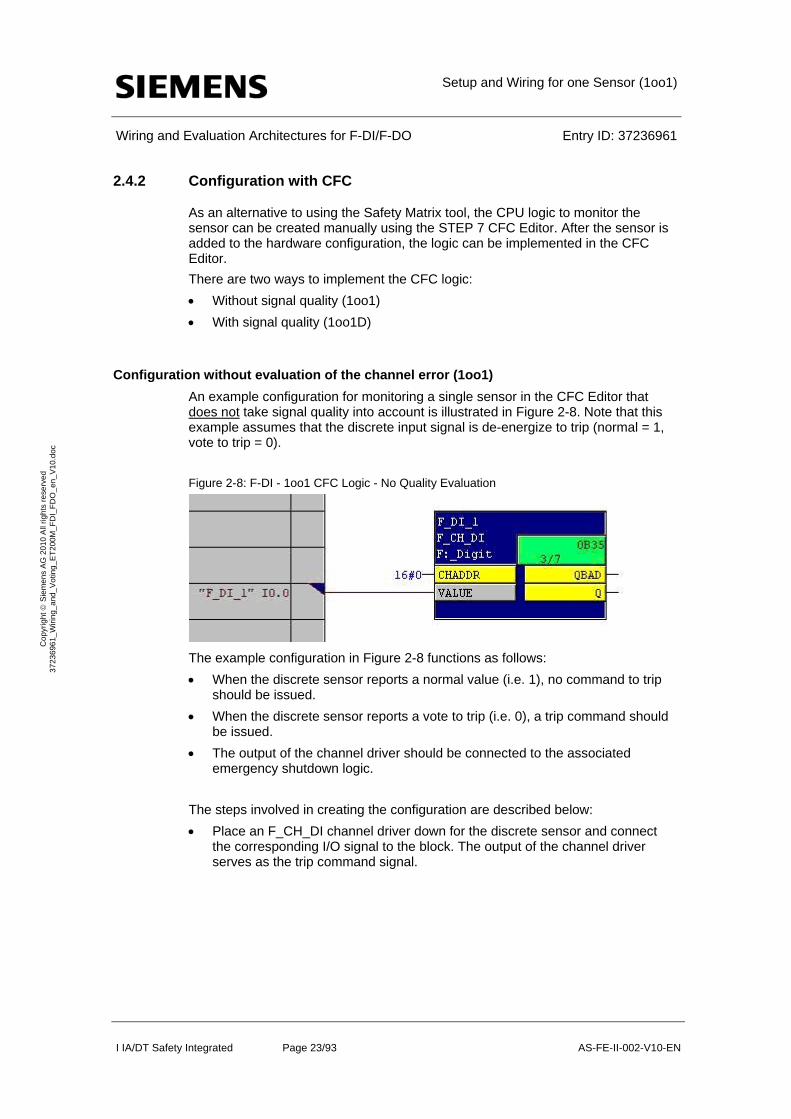
An example configuration for monitoring a single sensor in the CFC Editor that does not take signal quality into account is illustrated in Figure 2-8. Note that this example assumes that the discrete input signal is de-energize to trip (normal = 1, vote to trip = 0).
Figure 2-8: F-DI - 1oo1 CFC Logic - No Quality Evaluation
The example configuration in Figure 2-8 functions as follows:
When the discrete sensor reports a normal value (i.e. 1), no command to trip should be issued.
When the discrete sensor reports a vote to trip (i.e. 0), a trip command should be issued.
The output of the channel driver should be connected to the associated emergency shutdown logic.
The steps involved in creating the configuration are described below:
Place an F_CH_DI channel driver down for the discrete sensor and connect the corresponding I/O signal to the block. The output of the channel driver serves as the trip command signal.
Setup and Wiring for one Sensor (1oo1)
Wiring and Evaluation Architectures for F-DI/F-DO Entry ID: 37236961
I IA/DT Safety Integrated Page 24/93 AS-FE-II-002-V10-EN
Co
pyr
igh
t S
iem
en
s A
G 2
01
0 A
ll rig
hts
re
serv
ed
3
723
696
1_
Wiri
ng_
and
_V
otin
g_E
T2
00M
_F
DI_
FD
O_
en_
V1
0.d
oc
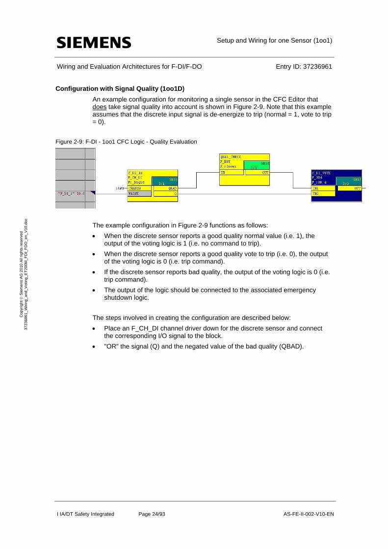
Configuration with Signal Quality (1oo1D)
An example configuration for monitoring a single sensor in the CFC Editor that does take signal quality into account is shown in Figure 2-9. Note that this example assumes that the discrete input signal is de-energize to trip (normal = 1, vote to trip = 0).
Figure 2-9: F-DI - 1oo1 CFC Logic - Quality Evaluation
The example configuration in Figure 2-9 functions as follows:
When the discrete sensor reports a good quality normal value (i.e. 1), the output of the voting logic is 1 (i.e. no command to trip).
When the discrete sensor reports a good quality vote to trip (i.e. 0), the output of the voting logic is 0 (i.e. trip command).
If the discrete sensor reports bad quality, the output of the voting logic is 0 (i.e. trip command).
The output of the logic should be connected to the associated emergency shutdown logic.
The steps involved in creating the configuration are described below:
Place an F_CH_DI channel driver down for the discrete sensor and connect the corresponding I/O signal to the block.
"OR" the signal (Q) and the negated value of the bad quality (QBAD).
Setup and Wiring for one Sensor (1oo1)
Wiring and Evaluation Architectures for F-DI/F-DO Entry ID: 37236961
I IA/DT Safety Integrated Page 25/93 AS-FE-II-002-V10-EN
Co
pyr
igh
t S
iem
en
s A
G 2
01
0 A
ll rig
hts
re
serv
ed
3
723
696
1_
Wiri
ng_
and
_V
otin
g_E
T2
00M
_F
DI_
FD
O_
en_
V1
0.d
oc
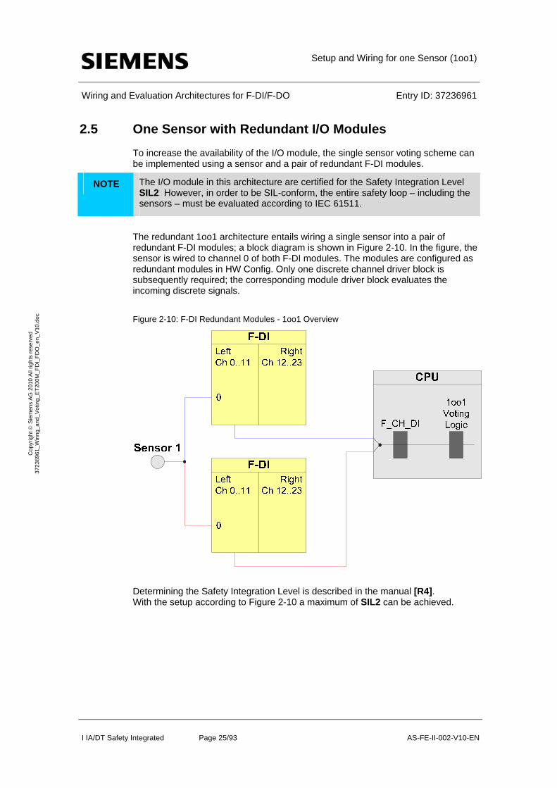
2.5 One Sensor with Redundant I/O Modules
To increase the availability of the I/O module, the single sensor voting scheme can be implemented using a sensor and a pair of redundant F-DI modules.
NOTE The I/O module in this architecture are certified for the Safety Integration Level SIL2 However, in order to be SIL-conform, the entire safety loop – including the sensors – must be evaluated according to IEC 61511.
The redundant 1oo1 architecture entails wiring a single sensor into a pair of redundant F-DI modules; a block diagram is shown in Figure 2-10. In the figure, the sensor is wired to channel 0 of both F-DI modules. The modules are configured as redundant modules in HW Config. Only one discrete channel driver block is subsequently required; the corresponding module driver block evaluates the incoming discrete signals.
Figure 2-10: F-DI Redundant Modules - 1oo1 Overview
Determining the Safety Integration Level is described in the manual [R4]. With the setup according to Figure 2-10 a maximum of SIL2 can be achieved.

Setup and Wiring for one Sensor (1oo1)
Wiring and Evaluation Architectures for F-DI/F-DO Entry ID: 37236961
I IA/DT Safety Integrated Page 26/93 AS-FE-II-002-V10-EN
Co
pyr
igh
t S
iem
en
s A
G 2
01
0 A
ll rig
hts
re
serv
ed
3
723
696
1_
Wiri
ng_
and
_V
otin
g_E
T2
00M
_F
DI_
FD
O_
en_
V1
0.d
oc
The following table shows when an error reaction function is triggered.
NOTE The redundancy does not increase the Safety Integration Level.
Table 2-3: Failure types
Component has failed ?
Sensor 1 F-DI 1 F-DI 2
Error reaction function has been
triggered?
no no no no
no no yes no
no yes no no
X yes yes yes
Yes3 X X yes
If sensor 1 or both F-DI fail, the error reaction function provides the safety function (through the failsafe system).
2.5.1 Calculating the PFD
The PFD value (Probability of Failure on Demand) describes the failure probability of the safety function.
Calculation formula of the PFD
The PFD value for this wiring and evaluation architecture is calculated using the formula below:
PFD(1oo1) = PFDSensor + 2 PFDF-DI + PFDCPU
The PFDF-DI and PFDCPU values are available in Chapter 6.
For one 1oo1 sensor the PFDSensor value is calculated using the following formula4::
3 In case of an error the sensor must go into the failsafe state. 4 The formula is taken out of IEC61508, IEC 61511 and VDI 2180 Sheet 4
1 1 2 I
oo DU
TPFD
Setup and Wiring for one Sensor (1oo1)
Wiring and Evaluation Architectures for F-DI/F-DO Entry ID: 37236961
I IA/DT Safety Integrated Page 27/93 AS-FE-II-002-V10-EN
Co
pyr
igh
t S
iem
en
s A
G 2
01
0 A
ll rig
hts
re
serv
ed
3
723
696
1_
Wiri
ng_
and
_V
otin
g_E
T2
00M
_F
DI_
FD
O_
en_
V1
0.d
oc
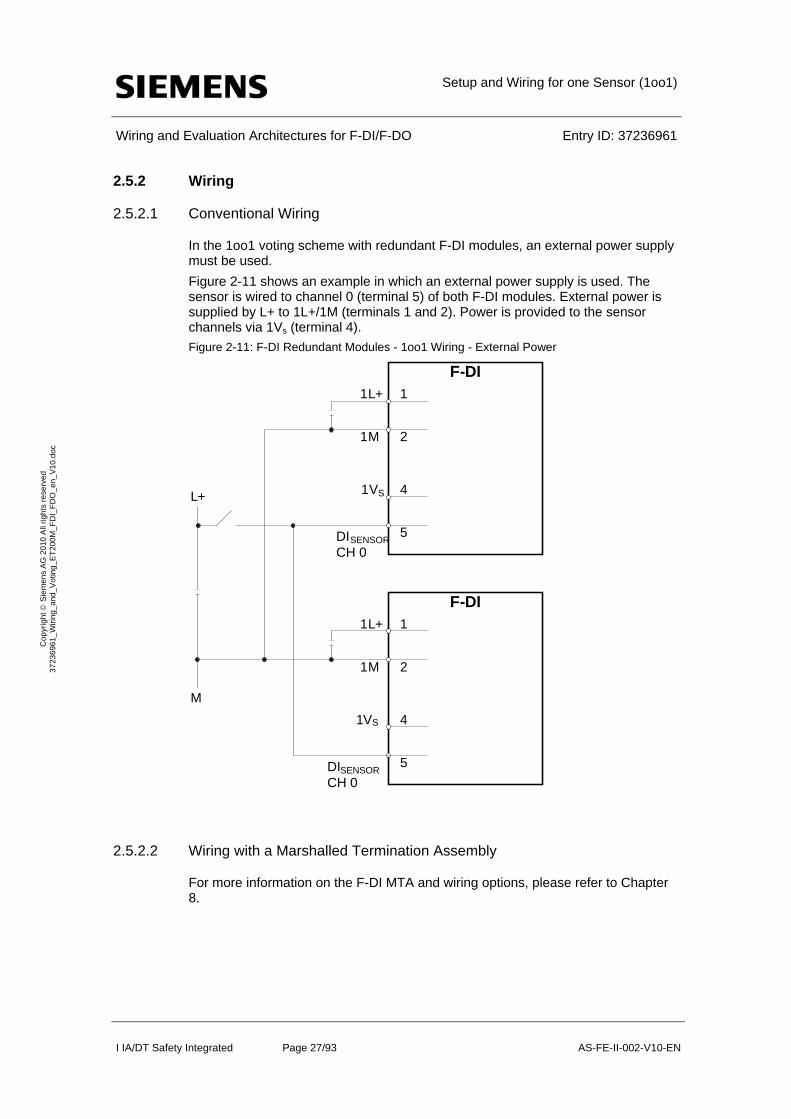
2.5.2 Wiring
2.5.2.1 Conventional Wiring
In the 1oo1 voting scheme with redundant F-DI modules, an external power supply must be used.
Figure 2-11 shows an example in which an external power supply is used. The sensor is wired to channel 0 (terminal 5) of both F-DI modules. External power is supplied by L+ to 1L+/1M (terminals 1 and 2). Power is provided to the sensor channels via 1Vs (terminal 4).
Figure 2-11: F-DI Redundant Modules - 1oo1 Wiring - External Power
2.5.2.2 Wiring with a Marshalled Termination Assembly
For more information on the F-DI MTA and wiring options, please refer to Chapter 8.
F-DI1L+
1M
1
2
1VS
DISENSOR
CH 0
4
5
L+
M
F-DI1L+
1M
1
2
1VS 4
5DISENSOR
CH 0
Setup and Wiring for one Sensor (1oo1)
Wiring and Evaluation Architectures for F-DI/F-DO Entry ID: 37236961
I IA/DT Safety Integrated Page 28/93 AS-FE-II-002-V10-EN
Co
pyr
igh
t S
iem
en
s A
G 2
01
0 A
ll rig
hts
re
serv
ed
3
723
696
1_
Wiri
ng_
and
_V
otin
g_E
T2
00M
_F
DI_
FD
O_
en_
V1
0.d
oc
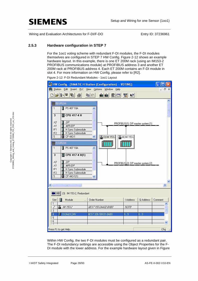
2.5.3 Hardware configuration in STEP 7
For the 1oo1 voting scheme with redundant F-DI modules, the F-DI modules themselves are configured in STEP 7 HW Config. Figure 2-12 shows an example hardware layout. In this example, there is one ET 200M rack (using an IM153-2 PROFIBUS communications module) at PROFIBUS address 3 and another ET 200M rack at PROFIBUS address 4. Each ET 200M contains an F-DI module in slot 4. For more information on HW Config, please refer to [R2].
Figure 2-12: F-DI Redundant Modules - 1oo1 Layout
Within HW Config, the two F-DI modules must be configured as a redundant pair. The F-DI redundancy settings are accessible using the Object Properties for the F-DI module with the lower address. For the example hardware layout given in Figure
Setup and Wiring for one Sensor (1oo1)
Wiring and Evaluation Architectures for F-DI/F-DO Entry ID: 37236961
I IA/DT Safety Integrated Page 29/93 AS-FE-II-002-V10-EN
Co
pyr
igh
t S
iem
en
s A
G 2
01
0 A
ll rig
hts
re
serv
ed
3
723
696
1_
Wiri
ng_
and
_V
otin
g_E
T2
00M
_F
DI_
FD
O_
en_
V1
0.d
oc
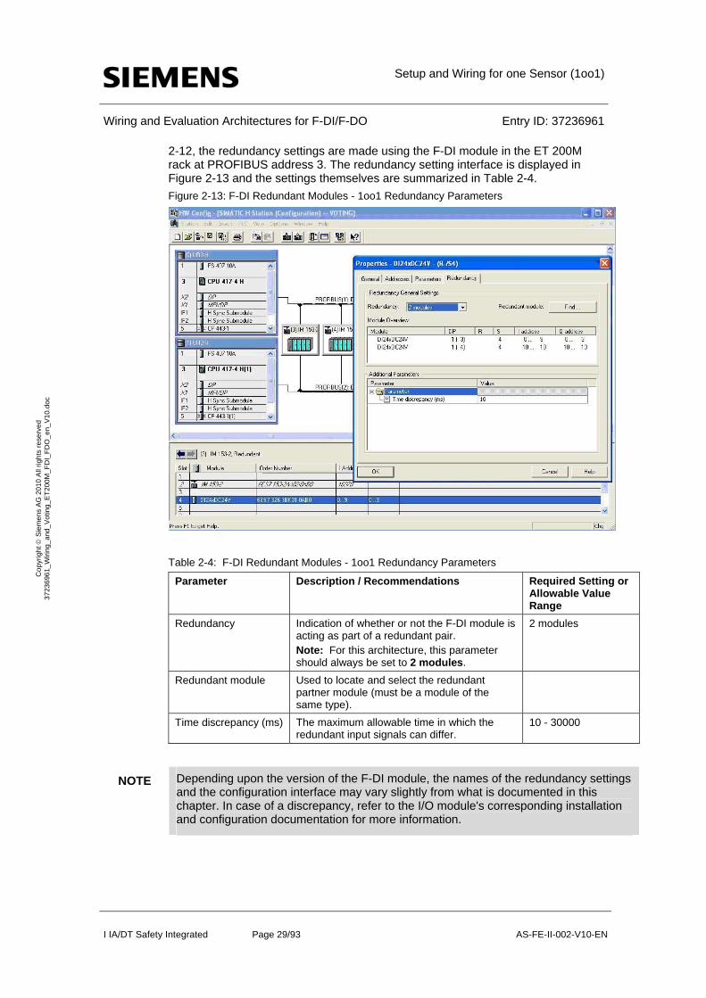
2-12, the redundancy settings are made using the F-DI module in the ET 200M rack at PROFIBUS address 3. The redundancy setting interface is displayed in Figure 2-13 and the settings themselves are summarized in Table 2-4.
Figure 2-13: F-DI Redundant Modules - 1oo1 Redundancy Parameters
Table 2-4: F-DI Redundant Modules - 1oo1 Redundancy Parameters
Parameter Description / Recommendations Required Setting or Allowable Value Range
Redundancy Indication of whether or not the F-DI module is acting as part of a redundant pair. Note: For this architecture, this parameter should always be set to 2 modules.
2 modules
Redundant module Used to locate and select the redundant partner module (must be a module of the same type).
Time discrepancy (ms) The maximum allowable time in which the redundant input signals can differ.
10 - 30000
NOTE Depending upon the version of the F-DI module, the names of the redundancy settings and the configuration interface may vary slightly from what is documented in this chapter. In case of a discrepancy, refer to the I/O module's corresponding installation and configuration documentation for more information.

Setup and Wiring for one Sensor (1oo1)
Wiring and Evaluation Architectures for F-DI/F-DO Entry ID: 37236961
I IA/DT Safety Integrated Page 30/93 AS-FE-II-002-V10-EN
Co
pyr
igh
t S
iem
en
s A
G 2
01
0 A
ll rig
hts
re
serv
ed
3
723
696
1_
Wiri
ng_
and
_V
otin
g_E
T2
00M
_F
DI_
FD
O_
en_
V1
0.d
oc
Once the redundancy settings are complete, the remainder of the hardware parameters for each of the redundant F-DI modules can be set using the guidelines provided back in Chapter 2.3 (Hardware configuration in STEP 7).
2.5.4 Configuring the logic
Though this voting scheme involves a pair of redundant F-DI modules, only one F_CH_DI channel driver function block is required in the logic configuration. The channel driver block can be automatically added to the logic by the SIMATIC Safety Matrix or manually added and configured using the STEP7 CFC Editor. In both cases, the channel driver should be connected to the discrete sensor signal from the F-DI module with the lower address.
The actual voting logic for monitoring a single sensor with redundant F-DI modules is the same as that given back in Chapters 2.4 (Configuring the logic
Configuration with Safety Matrix) and 2.4.2 (Configuration with CFC).
When the channel driver has been configured and the logic is complete, the configuration is compiled. With the compilation option to generate module drivers enable, the compilation automatically adds and configures a corresponding F_M_DI24 module driver to the logic. Using information from HW Config, the module driver is automatically configured to evaluate and handle the redundant discrete sensor signals.
Setup and Wiring for two Sensors (1oo2): Evaluation in the F-
DI Module
Wiring and Evaluation Architectures for F-DI/F-DO Entry ID: 37236961
I IA/DT Safety Integrated Page 31/93 AS-FE-II-002-V10-EN
Co
pyr
igh
t S
iem
en
s A
G 2
01
0 A
ll rig
hts
re
serv
ed
3
723
696
1_
Wiri
ng_
and
_V
otin
g_E
T2
00M
_F
DI_
FD
O_
en_
V1
0.d
oc
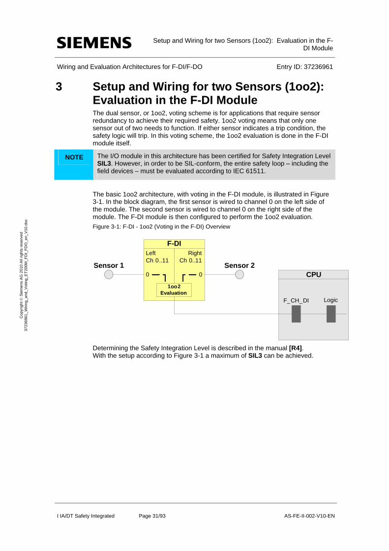
3 Setup and Wiring for two Sensors (1oo2): Evaluation in the F-DI Module The dual sensor, or 1oo2, voting scheme is for applications that require sensor redundancy to achieve their required safety. 1oo2 voting means that only one sensor out of two needs to function. If either sensor indicates a trip condition, the safety logic will trip. In this voting scheme, the 1oo2 evaluation is done in the F-DI module itself.
NOTE The I/O module in this architecture has been certified for Safety Integration Level SIL3. However, in order to be SIL-conform, the entire safety loop – including the field devices – must be evaluated according to IEC 61511.
The basic 1oo2 architecture, with voting in the F-DI module, is illustrated in Figure 3-1. In the block diagram, the first sensor is wired to channel 0 on the left side of the module. The second sensor is wired to channel 0 on the right side of the module. The F-DI module is then configured to perform the 1oo2 evaluation.
Figure 3-1: F-DI - 1oo2 (Voting in the F-DI) Overview
Determining the Safety Integration Level is described in the manual [R4]. With the setup according to Figure 3-1 a maximum of SIL3 can be achieved.
Sensor 1
Left Ch 0 ..11
0
F-DIRight
Ch 0..11Sensor 2
0
LogicF_ CH _ DI
CPU
1oo2Evaluation

Setup and Wiring for two Sensors (1oo2): Evaluation in the F-
DI Module
Wiring and Evaluation Architectures for F-DI/F-DO Entry ID: 37236961
I IA/DT Safety Integrated Page 32/93 AS-FE-II-002-V10-EN
Co
pyr
igh
t S
iem
en
s A
G 2
01
0 A
ll rig
hts
re
serv
ed
3
723
696
1_
Wiri
ng_
and
_V
otin
g_E
T2
00M
_F
DI_
FD
O_
en_
V1
0.d
oc
The following table shows when an error reaction function is triggered.
Table 3-1: Failure types
Component has failed ?
Sensor 1 Sensor 2 F-DI
Error reaction function has been
triggered?
no no no no
X X yes yes
X yes X yes
yes X X yes
If a sensor or the F-DI fails, the error reaction function provides the safety function (through the failsafe system).
3.1 Calculating the PFD
The PFD value (Probability of Failure on Demand) describes the failure probability of the failsafe function.
Calculation formula of the PFD
The PFD value for this wiring and evaluation architecture is calculated using the formula below:
PFD(1oo2) = PFDSensor + PFDF-DI + PFDCPU
The PFDF-DI and PFDCPU values are available in chapter 6.
For a 1oo2 sensor the PFDSensor value is calculated by the following formula5:
5 The formula is taken out of IEC61508, IEC 61511 and VDI 2180 Sheet 4
2 2
1 2 3 2 DU I I
oo DU
T TPFD
Setup and Wiring for two Sensors (1oo2): Evaluation in the F-
DI Module
Wiring and Evaluation Architectures for F-DI/F-DO Entry ID: 37236961
I IA/DT Safety Integrated Page 33/93 AS-FE-II-002-V10-EN
Co
pyr
igh
t S
iem
en
s A
G 2
01
0 A
ll rig
hts
re
serv
ed
3
723
696
1_
Wiri
ng_
and
_V
otin
g_E
T2
00M
_F
DI_
FD
O_
en_
V1
0.d
oc
3.2 Wiring
3.2.1 Conventional Wiring
In the 1oo2 internal voting scheme, the F-DI module can provide power to the sensors or an external supply can be used.
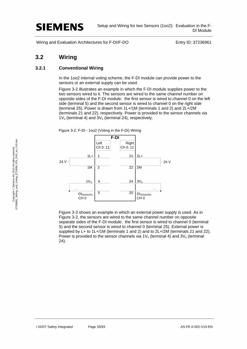
Figure 3-2 illustrates an example in which the F-DI module supplies power to the two sensors wired to it. The sensors are wired to the same channel number on opposite sides of the F-DI module: the first sensor is wired to channel 0 on the left side (terminal 5) and the second sensor is wired to channel 0 on the right side (terminal 25). Power is drawn from 1L+/1M (terminals 1 and 2) and 2L+/2M (terminals 21 and 22), respectively. Power is provided to the sensor channels via 1Vs (terminal 4) and 3Vs (terminal 24), respectively.
Figure 3-2: F-DI - 1oo2 (Voting in the F-DI) Wiring
F-DI
24 V
3VS
2L+
2M
DISENSOR2
CH 0
21
22
1L+
1M
1
2
24
25
1VS
DISENSOR1
CH 0
4
5
24 V
LeftCh 0..11
RightCh 0..11
Figure 3-3 shows an example in which an external power supply is used. As in Figure 3-2, the sensors are wired to the same channel number on opposite separate sides of the F-DI module: the first sensor is wired to channel 0 (terminal 5) and the second sensor is wired to channel 0 (terminal 25). External power is supplied by L+ to 1L+/1M (terminals 1 and 2) and to 2L+/2M (terminals 21 and 22). Power is provided to the sensor channels via 1Vs (terminal 4) and 3Vs (terminal 24).

Setup and Wiring for two Sensors (1oo2): Evaluation in the F-
DI Module
Wiring and Evaluation Architectures for F-DI/F-DO Entry ID: 37236961
I IA/DT Safety Integrated Page 34/93 AS-FE-II-002-V10-EN
Co
pyr
igh
t S
iem
en
s A
G 2
01
0 A
ll rig
hts
re
serv
ed
3
723
696
1_
Wiri
ng_
and
_V
otin
g_E
T2
00M
_F
DI_
FD
O_
en_
V1
0.d
oc
Figure 3-3: F-DI - 1oo2 (Voting in the F-DI) Wiring - External Power
3.2.2 Wiring with a Marshalled Termination Assembly
Siemens manufactures Marshalled Termination Assemblies (MTAs) that adapt field wiring to ET 200M signal modules. The MTA for the F-DI module simplifies wiring between the sensors and the F-DI module. For more information on the F-DI MTA and wiring options, please refer to Chapter 8.
3.3 Hardware configuration in STEP 7
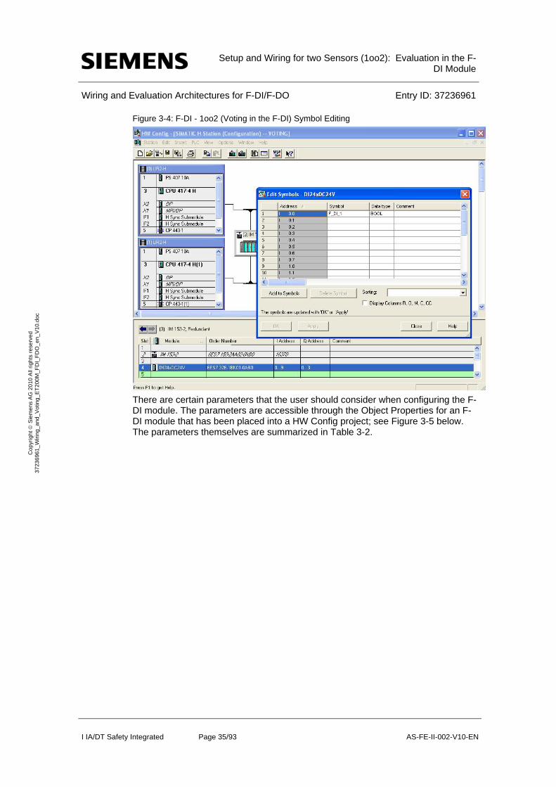
The F-DI module is configured in STEP 7 HW Config like any other ET 200M failsafe module. To proceed with the configuration, select the F-DI module (6ES7 326-1BK02-0AB0) from the STEP 7 HW Config Catalog and add it to an existing hardware configuration. For ease of configuration, assign a meaningful symbol name to the channel involved in the voting scheme. Note that since the F-DI module itself handles the 1oo2 signal selection, only one discrete sensor signal is made available to the CPU logic.
An example hardware layout using an F-DI module is shown in Figure 3-4. In this example, the two sensors are wired to the first channel on the left side and right side of the module; therefore, the first symbol address (I0.0) is used. Note that the use of an F-DI MTA does not require any special software configuration considerations. For more information on HW Config, please refer to [R2].
Setup and Wiring for two Sensors (1oo2): Evaluation in the F-
DI Module
Wiring and Evaluation Architectures for F-DI/F-DO Entry ID: 37236961
I IA/DT Safety Integrated Page 35/93 AS-FE-II-002-V10-EN
Co
pyr
igh
t S
iem
en
s A
G 2
01
0 A
ll rig
hts
re
serv
ed
3
723
696
1_
Wiri
ng_
and
_V
otin
g_E
T2
00M
_F
DI_
FD
O_
en_
V1
0.d
oc
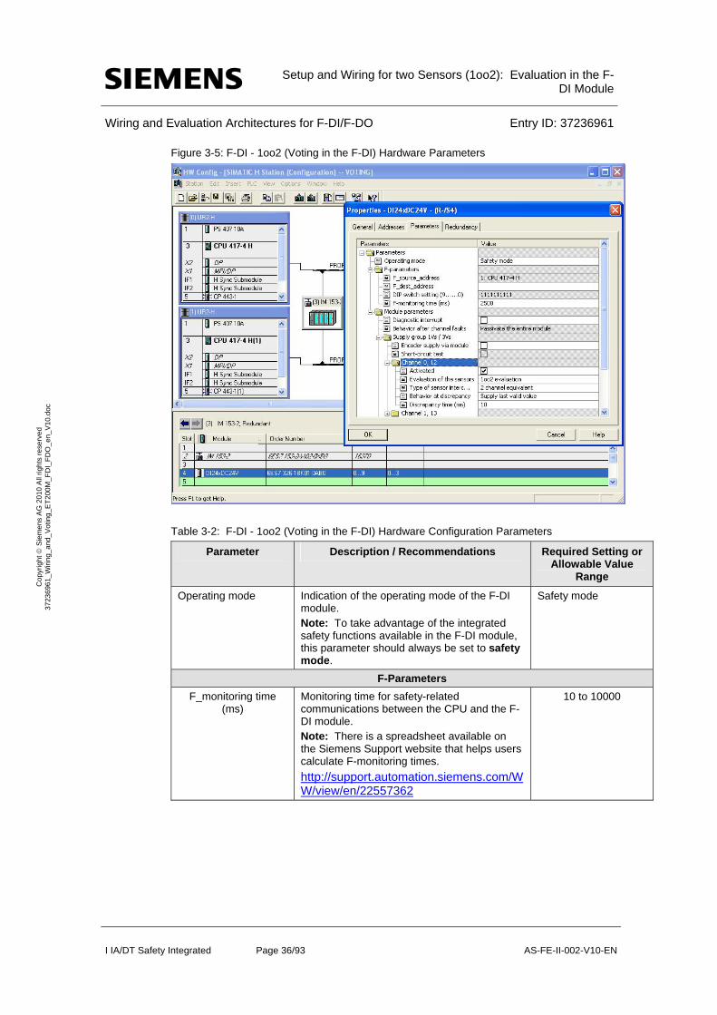
Figure 3-4: F-DI - 1oo2 (Voting in the F-DI) Symbol Editing
There are certain parameters that the user should consider when configuring the F-DI module. The parameters are accessible through the Object Properties for an F-DI module that has been placed into a HW Config project; see Figure 3-5 below. The parameters themselves are summarized in Table 3-2.
Setup and Wiring for two Sensors (1oo2): Evaluation in the F-
DI Module
Wiring and Evaluation Architectures for F-DI/F-DO Entry ID: 37236961
I IA/DT Safety Integrated Page 36/93 AS-FE-II-002-V10-EN
Co
pyr
igh
t S
iem
en
s A
G 2
01
0 A
ll rig
hts
re
serv
ed
3
723
696
1_
Wiri
ng_
and
_V
otin
g_E
T2
00M
_F
DI_
FD
O_
en_
V1
0.d
oc
Figure 3-5: F-DI - 1oo2 (Voting in the F-DI) Hardware Parameters
Table 3-2: F-DI - 1oo2 (Voting in the F-DI) Hardware Configuration Parameters
Parameter Description / Recommendations Required Setting or Allowable Value
Range
Operating mode Indication of the operating mode of the F-DI module. Note: To take advantage of the integrated safety functions available in the F-DI module, this parameter should always be set to safety mode.
Safety mode
F-Parameters
F_monitoring time (ms)
Monitoring time for safety-related communications between the CPU and the F-DI module. Note: There is a spreadsheet available on the Siemens Support website that helps users calculate F-monitoring times.
http://support.automation.siemens.com/WW/view/en/22557362
10 to 10000
Setup and Wiring for two Sensors (1oo2): Evaluation in the F-
DI Module
Wiring and Evaluation Architectures for F-DI/F-DO Entry ID: 37236961
I IA/DT Safety Integrated Page 37/93 AS-FE-II-002-V10-EN
Co
pyr
igh
t S
iem
en
s A
G 2
01
0 A
ll rig
hts
re
serv
ed
3
723
696
1_
Wiri
ng_
and
_V
otin
g_E
T2
00M
_F
DI_
FD
O_
en_
V1
0.d
oc
Parameter Description / Recommendations Required Setting or Allowable Value
Range
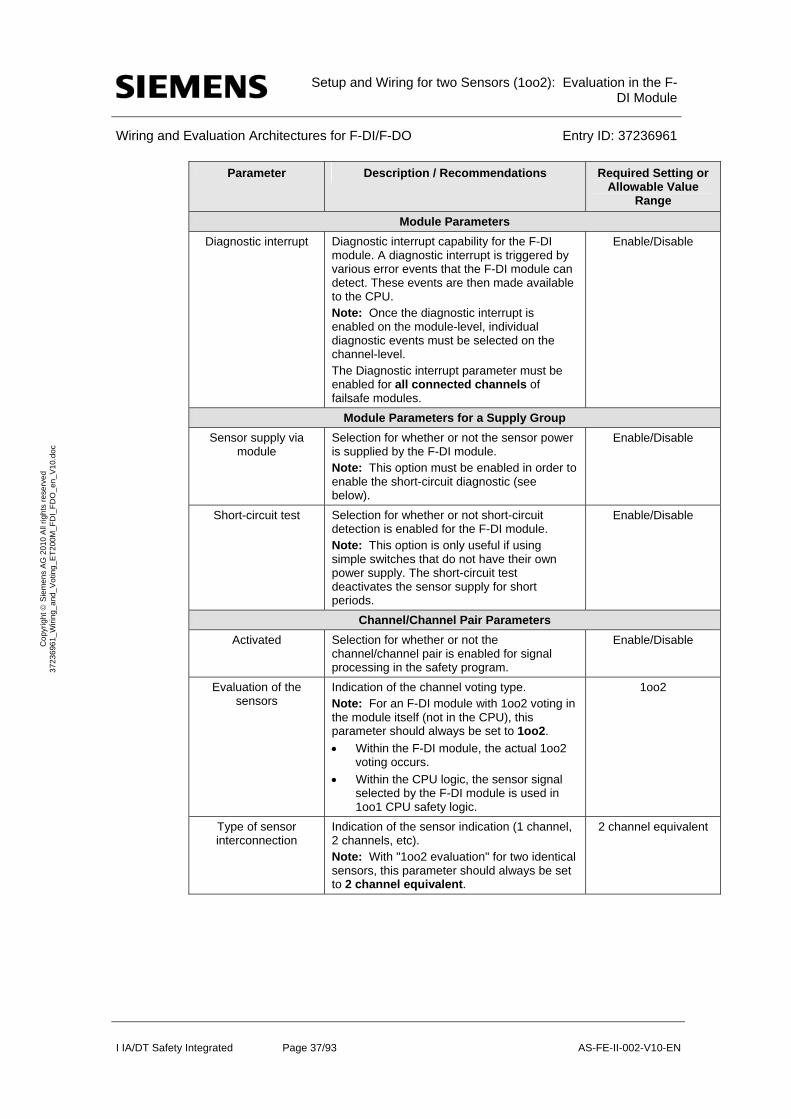
Module Parameters
Diagnostic interrupt Diagnostic interrupt capability for the F-DI module. A diagnostic interrupt is triggered by various error events that the F-DI module can detect. These events are then made available to the CPU. Note: Once the diagnostic interrupt is enabled on the module-level, individual diagnostic events must be selected on the channel-level. The Diagnostic interrupt parameter must be enabled for all connected channels of failsafe modules.
Enable/Disable
Module Parameters for a Supply Group
Sensor supply via module
Selection for whether or not the sensor power is supplied by the F-DI module. Note: This option must be enabled in order to enable the short-circuit diagnostic (see below).
Enable/Disable
Short-circuit test Selection for whether or not short-circuit detection is enabled for the F-DI module. Note: This option is only useful if using simple switches that do not have their own power supply. The short-circuit test deactivates the sensor supply for short periods.
Enable/Disable
Channel/Channel Pair Parameters
Activated Selection for whether or not the channel/channel pair is enabled for signal processing in the safety program.
Enable/Disable
Evaluation of the sensors
Indication of the channel voting type. Note: For an F-DI module with 1oo2 voting in the module itself (not in the CPU), this parameter should always be set to 1oo2.
Within the F-DI module, the actual 1oo2 voting occurs.
Within the CPU logic, the sensor signal selected by the F-DI module is used in 1oo1 CPU safety logic.
1oo2
Type of sensor interconnection
Indication of the sensor indication (1 channel, 2 channels, etc). Note: With "1oo2 evaluation" for two identical sensors, this parameter should always be set to 2 channel equivalent.
2 channel equivalent
Setup and Wiring for two Sensors (1oo2): Evaluation in the F-
DI Module
Wiring and Evaluation Architectures for F-DI/F-DO Entry ID: 37236961
I IA/DT Safety Integrated Page 38/93 AS-FE-II-002-V10-EN
Co
pyr
igh
t S
iem
en
s A
G 2
01
0 A
ll rig
hts
re
serv
ed
3
723
696
1_
Wiri
ng_
and
_V
otin
g_E
T2
00M
_F
DI_
FD
O_
en_
V1
0.d
oc
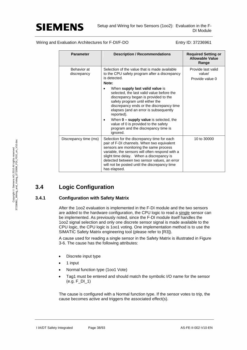
Parameter Description / Recommendations Required Setting or Allowable Value
Range
Behavior at discrepancy
Selection of the value that is made available to the CPU safety program after a discrepancy is detected. Note:
When supply last valid value is selected, the last valid value before the discrepancy began is provided to the safety program until either the discrepancy ends or the discrepancy time elapses (and an error is subsequently reported).
When 0 – supply value is selected, the value of 0 is provided to the safety program and the discrepancy time is ignored.
Provide last valid value/
Provide value 0
Discrepancy time (ms) Selection for the discrepancy time for each pair of F-DI channels. When two equivalent sensors are monitoring the same process variable, the sensors will often respond with a slight time delay. When a discrepancy is detected between two sensor values, an error will not be posted until the discrepancy time has elapsed.
10 to 30000
3.4 Logic Configuration
3.4.1 Configuration with Safety Matrix
After the 1oo2 evaluation is implemented in the F-DI module and the two sensors are added to the hardware configuration, the CPU logic to read a single sensor can be implemented. As previously noted, since the F-DI module itself handles the 1oo2 signal selection and only one discrete sensor signal is made available to the CPU logic, the CPU logic is 1oo1 voting. One implementation method is to use the SIMATIC Safety Matrix engineering tool (please refer to [R3]).
A cause used for reading a single sensor in the Safety Matrix is illustrated in Figure 3-6. The cause has the following attributes:
Discrete input type
1 input
Normal function type (1oo1 Vote)
Tag1 must be entered and should match the symbolic I/O name for the sensor (e.g. F_DI_1)
The cause is configured with a Normal function type. If the sensor votes to trip, the cause becomes active and triggers the associated effect(s).
Setup and Wiring for two Sensors (1oo2): Evaluation in the F-
DI Module
Wiring and Evaluation Architectures for F-DI/F-DO Entry ID: 37236961
I IA/DT Safety Integrated Page 39/93 AS-FE-II-002-V10-EN
Co
pyr
igh
t S
iem
en
s A
G 2
01
0 A
ll rig
hts
re
serv
ed
3
723
696
1_
Wiri
ng_
and
_V
otin
g_E
T2
00M
_F
DI_
FD
O_
en_
V1
0.d
oc
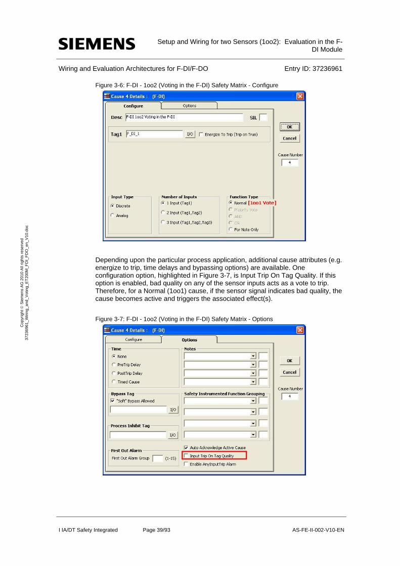
Figure 3-6: F-DI - 1oo2 (Voting in the F-DI) Safety Matrix - Configure
Depending upon the particular process application, additional cause attributes (e.g. energize to trip, time delays and bypassing options) are available. One configuration option, highlighted in Figure 3-7, is Input Trip On Tag Quality. If this option is enabled, bad quality on any of the sensor inputs acts as a vote to trip. Therefore, for a Normal (1oo1) cause, if the sensor signal indicates bad quality, the cause becomes active and triggers the associated effect(s).
Figure 3-7: F-DI - 1oo2 (Voting in the F-DI) Safety Matrix - Options

Setup and Wiring for two Sensors (1oo2): Evaluation in the F-
DI Module
Wiring and Evaluation Architectures for F-DI/F-DO Entry ID: 37236961
I IA/DT Safety Integrated Page 40/93 AS-FE-II-002-V10-EN
Co
pyr
igh
t S
iem
en
s A
G 2
01
0 A
ll rig
hts
re
serv
ed
3
723
696
1_
Wiri
ng_
and
_V
otin
g_E
T2
00M
_F
DI_
FD
O_
en_
V1
0.d
oc
3.4.2 Configuration with CFC
As an alternative to using the Safety Matrix tool, the CPU logic for reading a single sensor can be created manually using the STEP 7 CFC Editor. After the two sensors are added to the hardware configuration and are set for 1oo2 evaluation in the F-DI module, the 1oo1 voting logic can be implemented in the CFC Editor.
There are two ways to implement the CFC logic:
Without signal quality (1oo2)
With signal quality (1oo2D)
Configuration without Signal Quality (1oo2)
An example configuration for reading a single sensor in the CFC Editor that does not take signal quality into account is illustrated in Figure 3-8. Note that this example assumes that the discrete input signal is de-energize to trip (normal = 1, vote to trip = 0).
Figure 3-8: F-DI - 1oo2 (Voting in the F-DI) CFC Logic - No Quality Evaluation
The example configuration in Figure 3-8 functions as follows:
When the discrete sensor signal reports a normal value (i.e. 1), no command to trip should be issued.
When the discrete sensor signal reports a vote to trip (i.e. 0), a trip command should be issued.
The output of the channel driver should be connected to the associated emergency shutdown logic.
The steps involved in creating the configuration are described below:
Place an F_CH_DI channel driver down for the discrete sensor input and connect the corresponding I/O signal to the block. The output of the channel driver serves as the trip command signal.
Configuration with Signal Quality (1oo2D)
An example configuration for reading a single sensor in the CFC Editor that does take signal quality into account is shown in
Figure 3-9. Note that this example assumes that the discrete input signal is de-energize to trip (normal = 1, vote to trip = 0).
Setup and Wiring for two Sensors (1oo2): Evaluation in the F-
DI Module
Wiring and Evaluation Architectures for F-DI/F-DO Entry ID: 37236961
I IA/DT Safety Integrated Page 41/93 AS-FE-II-002-V10-EN
Co
pyr
igh
t S
iem
en
s A
G 2
01
0 A
ll rig
hts
re
serv
ed
3
723
696
1_
Wiri
ng_
and
_V
otin
g_E
T2
00M
_F
DI_
FD
O_
en_
V1
0.d
oc
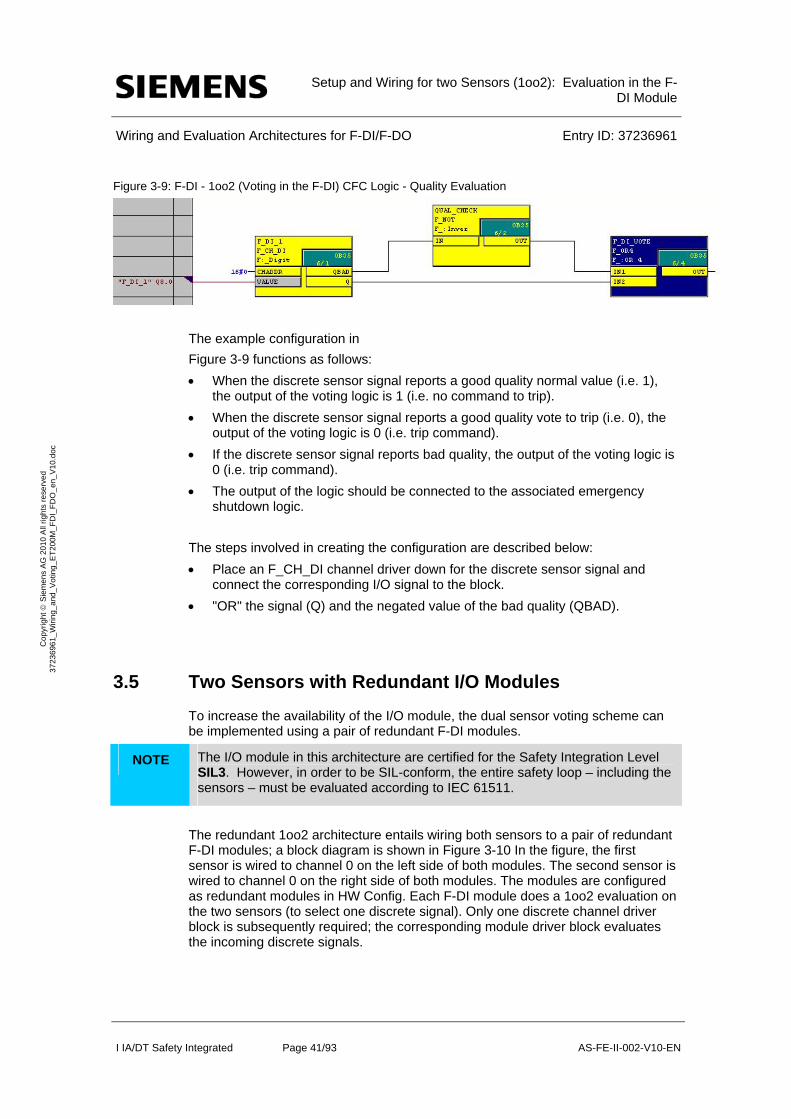
Figure 3-9: F-DI - 1oo2 (Voting in the F-DI) CFC Logic - Quality Evaluation
The example configuration in
Figure 3-9 functions as follows:
When the discrete sensor signal reports a good quality normal value (i.e. 1), the output of the voting logic is 1 (i.e. no command to trip).
When the discrete sensor signal reports a good quality vote to trip (i.e. 0), the output of the voting logic is 0 (i.e. trip command).
If the discrete sensor signal reports bad quality, the output of the voting logic is 0 (i.e. trip command).
The output of the logic should be connected to the associated emergency shutdown logic.
The steps involved in creating the configuration are described below:
Place an F_CH_DI channel driver down for the discrete sensor signal and connect the corresponding I/O signal to the block.
"OR" the signal (Q) and the negated value of the bad quality (QBAD).
3.5 Two Sensors with Redundant I/O Modules
To increase the availability of the I/O module, the dual sensor voting scheme can be implemented using a pair of redundant F-DI modules.
NOTE The I/O module in this architecture are certified for the Safety Integration Level SIL3. However, in order to be SIL-conform, the entire safety loop – including the sensors – must be evaluated according to IEC 61511.
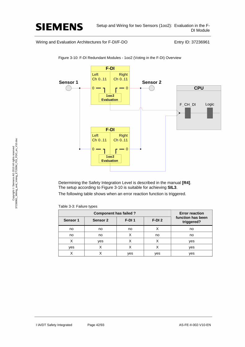
The redundant 1oo2 architecture entails wiring both sensors to a pair of redundant F-DI modules; a block diagram is shown in Figure 3-10 In the figure, the first sensor is wired to channel 0 on the left side of both modules. The second sensor is wired to channel 0 on the right side of both modules. The modules are configured as redundant modules in HW Config. Each F-DI module does a 1oo2 evaluation on the two sensors (to select one discrete signal). Only one discrete channel driver block is subsequently required; the corresponding module driver block evaluates the incoming discrete signals.
Setup and Wiring for two Sensors (1oo2): Evaluation in the F-
DI Module
Wiring and Evaluation Architectures for F-DI/F-DO Entry ID: 37236961
I IA/DT Safety Integrated Page 42/93 AS-FE-II-002-V10-EN
Co
pyr
igh
t S
iem
en
s A
G 2
01
0 A
ll rig
hts
re
serv
ed
3
723
696
1_
Wiri
ng_
and
_V
otin
g_E
T2
00M
_F
DI_
FD
O_
en_
V1
0.d
oc
Figure 3-10: F-DI Redundant Modules - 1oo2 (Voting in the F-DI) Overview
Determining the Safety Integration Level is described in the manual [R4]. The setup according to Figure 3-10 is suitable for achieving SIL3.
The following table shows when an error reaction function is triggered.
Table 3-3: Failure types
Component has failed ?
Sensor 1 Sensor 2 F-DI 1 F-DI 2
Error reaction function has been
triggered?
no no no X no
no no X no no
X yes X X yes
yes X X X yes
X X yes yes yes
Left Ch 0 ..11
0
F-DIRight
Ch 0..11
0 CPUSensor 1 Sensor 2
1oo2Evaluation
LogicF_ CH _ DI
Left Ch 0 ..11
0
F-DIRight
Ch 0..11
0
1oo2Evaluation

Setup and Wiring for two Sensors (1oo2): Evaluation in the F-
DI Module
Wiring and Evaluation Architectures for F-DI/F-DO Entry ID: 37236961
I IA/DT Safety Integrated Page 43/93 AS-FE-II-002-V10-EN
Co
pyr
igh
t S
iem
en
s A
G 2
01
0 A
ll rig
hts
re
serv
ed
3
723
696
1_
Wiri
ng_
and
_V
otin
g_E
T2
00M
_F
DI_
FD
O_
en_
V1
0.d
oc
If a sensor or both F-DI fail, the error reaction function provides the safety function (through the failsafe system).
NOTE The redundancy does not increase the Safety Integration Level.
3.5.1 Calculating the PFD
The PFD value (Probability of Failure on Demand) describes the failure probability of the failsafe function.
Calculation formula of the PFD
The PFD value for this wiring and evaluation architecture is calculated using the formula below:
PFD(1oo2) = PFDSensor + 2 PFDF-DI + PFDCPU
The PFDF-DI and PFDCPU values can be found in Section 6..
For a 1oo2 Sensor the PFDSensor is calculated by this formula6:
6 The formula is taken out of IEC61508, IEC 61511 and VDI 2180 Blatt 4, see appendix
2 2
1 2 3 2 DU I I
oo DU
T TPFD
Setup and Wiring for two Sensors (1oo2): Evaluation in the F-
DI Module
Wiring and Evaluation Architectures for F-DI/F-DO Entry ID: 37236961
I IA/DT Safety Integrated Page 44/93 AS-FE-II-002-V10-EN
Co
pyr
igh
t S
iem
en
s A
G 2
01
0 A
ll rig
hts
re
serv
ed
3
723
696
1_
Wiri
ng_
and
_V
otin
g_E
T2
00M
_F
DI_
FD
O_
en_
V1
0.d
oc
3.5.2 Wiring
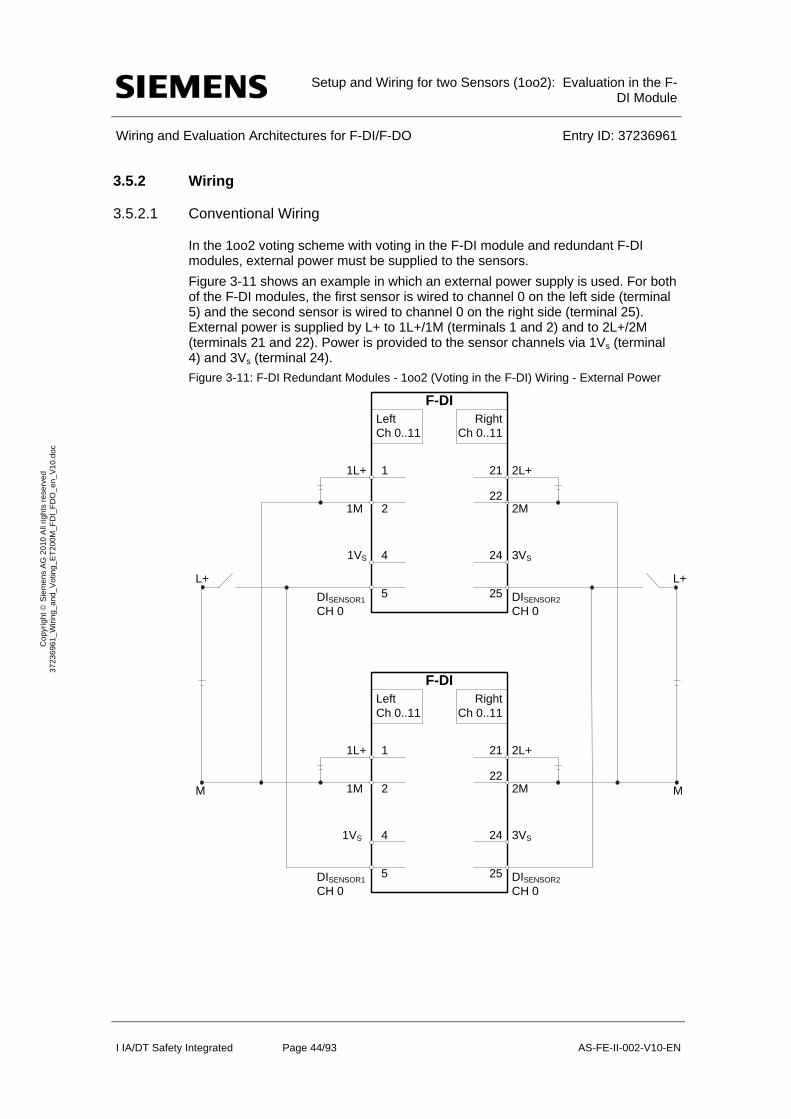
3.5.2.1 Conventional Wiring
In the 1oo2 voting scheme with voting in the F-DI module and redundant F-DI modules, external power must be supplied to the sensors.
Figure 3-11 shows an example in which an external power supply is used. For both of the F-DI modules, the first sensor is wired to channel 0 on the left side (terminal 5) and the second sensor is wired to channel 0 on the right side (terminal 25). External power is supplied by L+ to 1L+/1M (terminals 1 and 2) and to 2L+/2M (terminals 21 and 22). Power is provided to the sensor channels via 1Vs (terminal 4) and 3Vs (terminal 24).
Figure 3-11: F-DI Redundant Modules - 1oo2 (Voting in the F-DI) Wiring - External Power
F-DI
1L+
1M
1
2
1VS 4
5L+
M
F-DI
1L+
1M
1
2
1VS 4
5DISENSOR1
CH 0
2L+
2M
21
22
3VS24
25
2L+
2M
21
22
3VS24
25
L+
M
LeftCh 0..11
RightCh 0..11
LeftCh 0..11
RightCh 0..11
DISENSOR1
CH 0DISENSOR2
CH 0
DISENSOR2
CH 0

Setup and Wiring for two Sensors (1oo2): Evaluation in the F-
DI Module
Wiring and Evaluation Architectures for F-DI/F-DO Entry ID: 37236961
I IA/DT Safety Integrated Page 45/93 AS-FE-II-002-V10-EN
Co
pyr
igh
t S
iem
en
s A
G 2
01
0 A
ll rig
hts
re
serv
ed
3
723
696
1_
Wiri
ng_
and
_V
otin
g_E
T2
00M
_F
DI_
FD
O_
en_
V1
0.d
oc
3.5.2.2 Wiring with a Marshalled Termination Assembly
For more information on the F-DI MTA and wiring options, please refer to Chapter 8.
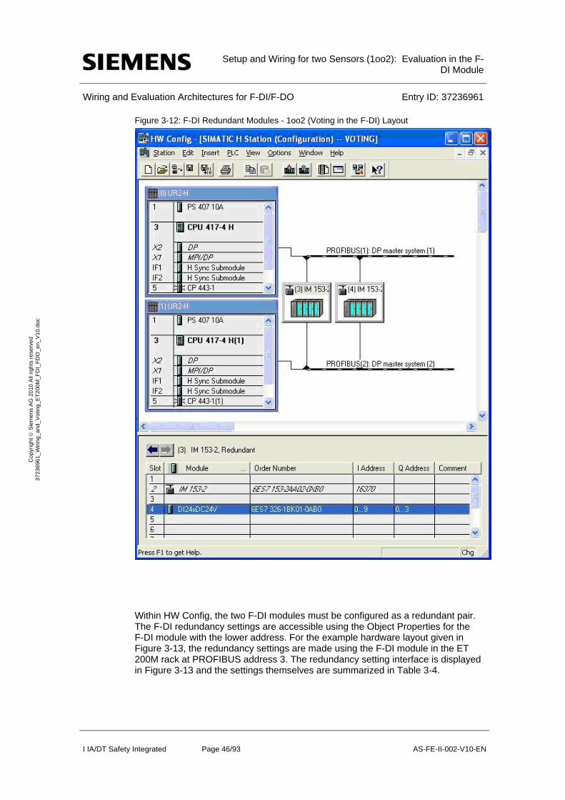
3.5.3 Hardware configuration in STEP 7
For the 1oo2 voting scheme with voting in the F-DI module and redundant F-DI modules, the F-DI modules themselves are configured in STEP 7 HW Config. Figure 3-12 shows an example hardware layout. In this example, there is one ET 200M rack (using an IM153-2 PROFIBUS communications module) at PROFIBUS address 3 and another ET 200M rack at PROFIBUS address 4. Each ET 200M rack contains an F-DI module in slot 4. For more information on HW Config, please refer to [R2].
Setup and Wiring for two Sensors (1oo2): Evaluation in the F-
DI Module
Wiring and Evaluation Architectures for F-DI/F-DO Entry ID: 37236961
I IA/DT Safety Integrated Page 46/93 AS-FE-II-002-V10-EN
Co
pyr
igh
t S
iem
en
s A
G 2
01
0 A
ll rig
hts
re
serv
ed
3
723
696
1_
Wiri
ng_
and
_V
otin
g_E
T2
00M
_F
DI_
FD
O_
en_
V1
0.d
oc
Figure 3-12: F-DI Redundant Modules - 1oo2 (Voting in the F-DI) Layout
Within HW Config, the two F-DI modules must be configured as a redundant pair. The F-DI redundancy settings are accessible using the Object Properties for the F-DI module with the lower address. For the example hardware layout given in Figure 3-13, the redundancy settings are made using the F-DI module in the ET 200M rack at PROFIBUS address 3. The redundancy setting interface is displayed in Figure 3-13 and the settings themselves are summarized in Table 3-4.
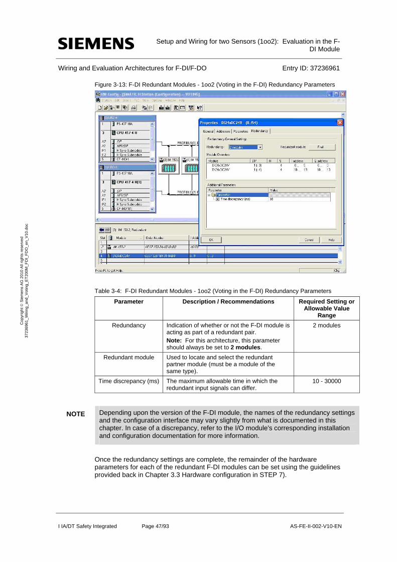
Setup and Wiring for two Sensors (1oo2): Evaluation in the F-
DI Module
Wiring and Evaluation Architectures for F-DI/F-DO Entry ID: 37236961
I IA/DT Safety Integrated Page 47/93 AS-FE-II-002-V10-EN
Co
pyr
igh
t S
iem
en
s A
G 2
01
0 A
ll rig
hts
re
serv
ed
3
723
696
1_
Wiri
ng_
and
_V
otin
g_E
T2
00M
_F
DI_
FD
O_
en_
V1
0.d
oc
Figure 3-13: F-DI Redundant Modules - 1oo2 (Voting in the F-DI) Redundancy Parameters
Table 3-4: F-DI Redundant Modules - 1oo2 (Voting in the F-DI) Redundancy Parameters
Parameter Description / Recommendations Required Setting or Allowable Value
Range
Redundancy Indication of whether or not the F-DI module is acting as part of a redundant pair. Note: For this architecture, this parameter should always be set to 2 modules.
2 modules
Redundant module Used to locate and select the redundant partner module (must be a module of the same type).
Time discrepancy (ms) The maximum allowable time in which the redundant input signals can differ.
10 - 30000
NOTE Depending upon the version of the F-DI module, the names of the redundancy settings and the configuration interface may vary slightly from what is documented in this chapter. In case of a discrepancy, refer to the I/O module's corresponding installation and configuration documentation for more information.
Once the redundancy settings are complete, the remainder of the hardware parameters for each of the redundant F-DI modules can be set using the guidelines provided back in Chapter 3.3 Hardware configuration in STEP 7).

Setup and Wiring for two Sensors (1oo2): Evaluation in the F-
DI Module
Wiring and Evaluation Architectures for F-DI/F-DO Entry ID: 37236961
I IA/DT Safety Integrated Page 48/93 AS-FE-II-002-V10-EN
Co
pyr
igh
t S
iem
en
s A
G 2
01
0 A
ll rig
hts
re
serv
ed
3
723
696
1_
Wiri
ng_
and
_V
otin
g_E
T2
00M
_F
DI_
FD
O_
en_
V1
0.d
oc
3.5.4 Logic Configuration
Though this voting scheme involves a pair of redundant F-DI modules, only one F_CH_DI channel driver function block is required in the logic configuration. The channel driver block can be automatically added to the logic by the SIMATIC Safety Matrix or manually added and configured using the STEP 7 CFC Editor. In both cases, the channel driver should be connected to the discrete sensor signal from the F-DI module with the lower address.
The actual voting logic for the 1oo2 voting scheme with redundant F-DI modules is the same as that given back in Chapters 3.4 “Configuration with Safety Matrix” and 3.4.2"Configuration with CFC"
When the channel driver has been configured and the voting logic is complete, the configuration is compiled. With the compilation option to generate module drivers enable, the compilation automatically adds and configures a corresponding F_M_DI24 module driver to the logic. Using information from HW Config, the module driver is automatically configured to evaluate and handle the redundant discrete sensor signals.
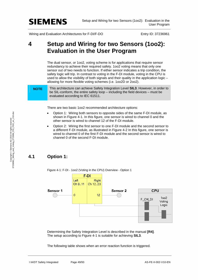
Setup and Wiring for two Sensors (1oo2): Evaluation in the
User Program
Wiring and Evaluation Architectures for F-DI/F-DO Entry ID: 37236961
I IA/DT Safety Integrated Page 49/93 AS-FE-II-002-V10-EN
Co
pyr
igh
t S
iem
en
s A
G 2
01
0 A
ll rig
hts
re
serv
ed
3
723
696
1_
Wiri
ng_
and
_V
otin
g_E
T2
00M
_F
DI_
FD
O_
en_
V1
0.d
oc
4 Setup and Wiring for two Sensors (1oo2): Evaluation in the User Program
The dual sensor, or 1oo2, voting scheme is for applications that require sensor redundancy to achieve their required safety. 1oo2 voting means that only one sensor out of two needs to function. If either sensor indicates a trip condition, the safety logic will trip. In contrast to voting in the F-DI module, voting in the CPU is used to allow the visibility of both signals and their quality in the application logic – allowing for more flexible voting schemes (i.e. 1oo2D or 2oo2).
NOTE This architecture can achieve Safety Integration Level SIL3. However, in order to be SIL-conform, the entire safety loop – including the field devices – must be evaluated according to IEC 61511.
There are two basic 1oo2 recommended architecture options:
Option 1: Wiring both sensors to opposite sides of the same F-DI module, as shown in Figure 4-1. In this figure, one sensor is wired to channel 0 and the other sensor is wired to channel 12 of the F-DI module.
Option 2: Wiring the first sensor to one F-DI module and the second sensor to a different F-DI module, as illustrated in Figure 4-2 In this figure, one sensor is wired to channel 0 of the first F-DI module and the second sensor is wired to channel 0 of the second F-DI module.
4.1 Option 1:
Figure 4-1: F-DI - 1oo2 (Voting in the CPU) Overview - Option 1
Determining the Safety Integration Level is described in the manual [R4]. The setup according to Figure 4-1 is suitable for achieving SIL3.
The following table shows when an error reaction function is triggered.

Setup and Wiring for two Sensors (1oo2): Evaluation in the
User Program
Wiring and Evaluation Architectures for F-DI/F-DO Entry ID: 37236961
I IA/DT Safety Integrated Page 50/93 AS-FE-II-002-V10-EN
Co
pyr
igh
t S
iem
en
s A
G 2
01
0 A
ll rig
hts
re
serv
ed
3
723
696
1_
Wiri
ng_
and
_V
otin
g_E
T2
00M
_F
DI_
FD
O_
en_
V1
0.d
oc
Table 4-1: Failure types for SIL 3 Logic
Component has failed ?
Sensor 1 Sensor 2 F-DI
Error reaction function has been
triggered?
no no no no
X yes X yes
yes X X yes
X X yes yes
If a sensor or the F-DI fails, the error reaction function provides the safety function (through the failsafe system).
4.1.1 Calculating the PFD (option 1)
The PFD value (Probability of Failure on Demand) describes the failure probability of the failsafe function.
Calculation formula of the PFD
The PFD value for this wiring and evaluation architecture is calculated using the formula below:
PFD(1oo2) = PFDSensor + PFDF-DI + PFDCPU
The PFDF-DI and PFDCPU values are available in Section 6.
For a 1oo2 sensor the PFDSensor value is calculated using the following formulafn :
2 2
1 2 3 2 DU I I
oo DU
T TPFD
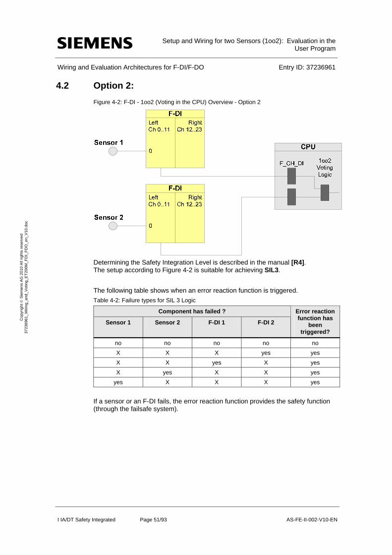
Setup and Wiring for two Sensors (1oo2): Evaluation in the
User Program
Wiring and Evaluation Architectures for F-DI/F-DO Entry ID: 37236961
I IA/DT Safety Integrated Page 51/93 AS-FE-II-002-V10-EN
Co
pyr
igh
t S
iem
en
s A
G 2
01
0 A
ll rig
hts
re
serv
ed
3
723
696
1_
Wiri
ng_
and
_V
otin
g_E
T2
00M
_F
DI_
FD
O_
en_
V1
0.d
oc
4.2 Option 2:
Figure 4-2: F-DI - 1oo2 (Voting in the CPU) Overview - Option 2
Determining the Safety Integration Level is described in the manual [R4]. The setup according to Figure 4-2 is suitable for achieving SIL3.
The following table shows when an error reaction function is triggered.
Table 4-2: Failure types for SIL 3 Logic
Component has failed ?
Sensor 1 Sensor 2 F-DI 1 F-DI 2
Error reaction function has
been triggered?
no no no no no
X X X yes yes
X X yes X yes
X yes X X yes
yes X X X yes
If a sensor or an F-DI fails, the error reaction function provides the safety function (through the failsafe system).

Setup and Wiring for two Sensors (1oo2): Evaluation in the
User Program
Wiring and Evaluation Architectures for F-DI/F-DO Entry ID: 37236961
I IA/DT Safety Integrated Page 52/93 AS-FE-II-002-V10-EN
Co
pyr
igh
t S
iem
en
s A
G 2
01
0 A
ll rig
hts
re
serv
ed
3
723
696
1_
Wiri
ng_
and
_V
otin
g_E
T2
00M
_F
DI_
FD
O_
en_
V1
0.d
oc
4.2.1 Calculating the PFD (option 2)
The PFD value (Probability of Failure on Demand) describes the failure probability of the failsafe function.
Calculation formula of the PFD
The PFD value for this wiring and evaluation architecture is calculated using the formula below:
PFD(1oo2) = PFDSensor + 2 PFDF-DI + PFDCPU
The PFDF-DI and PFDCPU values are available in Section 6.
For a 1oo2 sensor the PFDSensor value is calculated using the following formulafn :
4.3 Wiring
4.3.1 Conventional Wiring
In the 1oo2 voting scheme, the F-DI module(s) can provide power to the sensors or an external supply can be used.
Figure 4-3 illustrates an example in which one F-DI module supplies power to the two sensors wired to it. To achieve a higher SIL, the sensors are wired to separate sides of the F-DI module: the first sensor is wired to channel 0 (terminal 5) and the second sensor is wired to channel 12 (terminal 25). Power is drawn from 1L+/1M (terminals 1 and 2) and 2L+/2M (terminals 21 and 22), respectively. Power is provided to the sensor channels via 1Vs (terminal 4) and 3Vs (terminal 24), respectively.
2 2
1 2 3 2 DU I I
oo DU
T TPFD
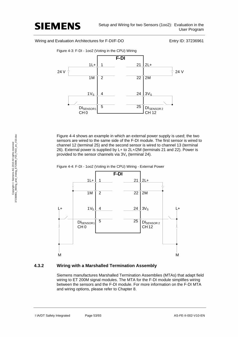
Setup and Wiring for two Sensors (1oo2): Evaluation in the
User Program
Wiring and Evaluation Architectures for F-DI/F-DO Entry ID: 37236961
I IA/DT Safety Integrated Page 53/93 AS-FE-II-002-V10-EN
Co
pyr
igh
t S
iem
en
s A
G 2
01
0 A
ll rig
hts
re
serv
ed
3
723
696
1_
Wiri
ng_
and
_V
otin
g_E
T2
00M
_F
DI_
FD
O_
en_
V1
0.d
oc
Figure 4-3: F-DI - 1oo2 (Voting in the CPU) Wiring
Figure 4-4 shows an example in which an external power supply is used; the two sensors are wired to the same side of the F-DI module. The first sensor is wired to channel 12 (terminal 25) and the second sensor is wired to channel 13 (terminal 26). External power is supplied by L+ to 2L+/2M (terminals 21 and 22). Power is provided to the sensor channels via 3Vs (terminal 24).
Figure 4-4: F-DI - 1oo2 (Voting in the CPU) Wiring - External Power
4.3.2 Wiring with a Marshalled Termination Assembly
Siemens manufactures Marshalled Termination Assemblies (MTAs) that adapt field wiring to ET 200M signal modules. The MTA for the F-DI module simplifies wiring between the sensors and the F-DI module. For more information on the F-DI MTA and wiring options, please refer to Chapter 8.
F-DI
24 V
3VS
2L+
2M
DISENSOR 2
CH 12
21
22
1 L +
1 M
1
2
24
25
1VS
DISENSOR 1CH 0
4
5
24 V
F-DI2L+
2M
21
22
3VS
DISENSOR 2
CH 12
24
25
L+
M
1 L +
1 M
1
2
1 VS
DISENSOR 1CH 0
4
5
L+
M
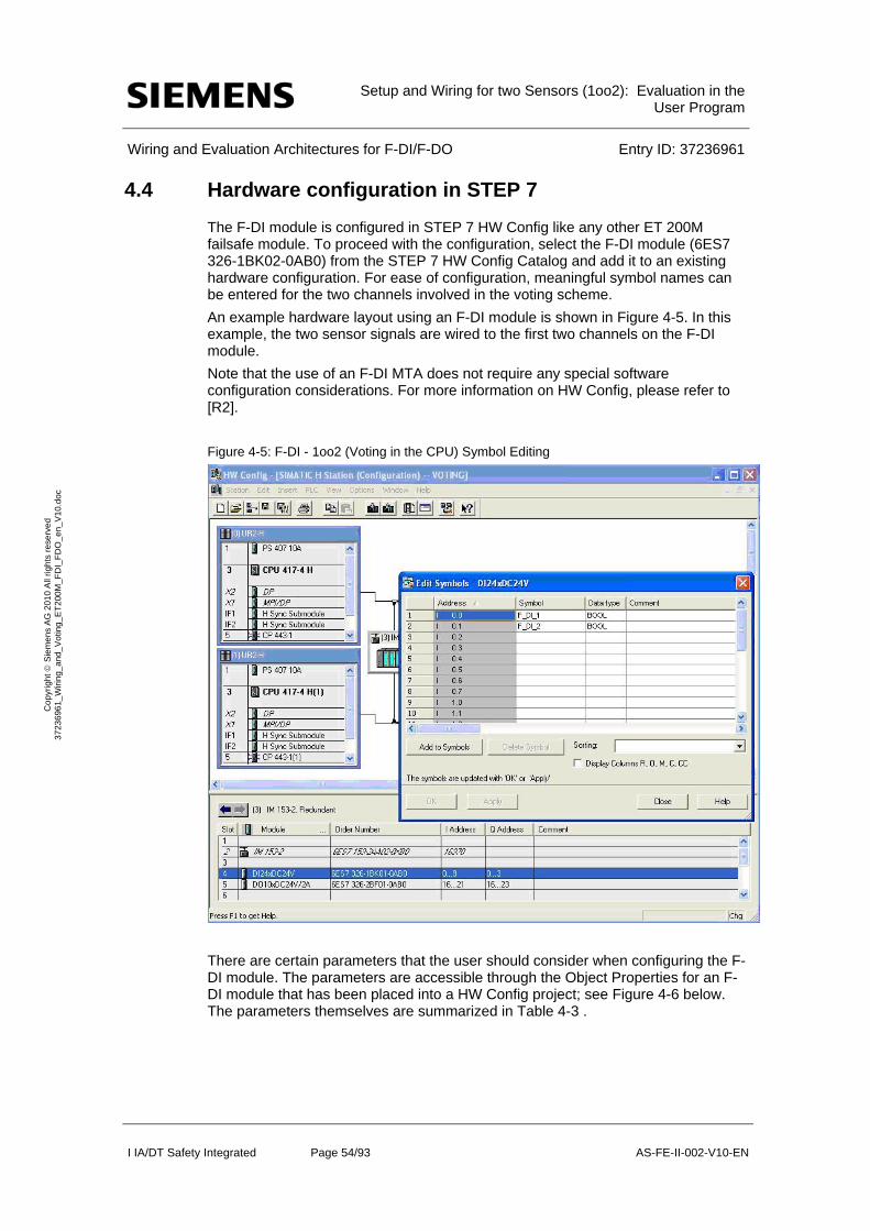
Setup and Wiring for two Sensors (1oo2): Evaluation in the
User Program
Wiring and Evaluation Architectures for F-DI/F-DO Entry ID: 37236961
I IA/DT Safety Integrated Page 54/93 AS-FE-II-002-V10-EN
Co
pyr
igh
t S
iem
en
s A
G 2
01
0 A
ll rig
hts
re
serv
ed
3
723
696
1_
Wiri
ng_
and
_V
otin
g_E
T2
00M
_F
DI_
FD
O_
en_
V1
0.d
oc
4.4 Hardware configuration in STEP 7
The F-DI module is configured in STEP 7 HW Config like any other ET 200M failsafe module. To proceed with the configuration, select the F-DI module (6ES7 326-1BK02-0AB0) from the STEP 7 HW Config Catalog and add it to an existing hardware configuration. For ease of configuration, meaningful symbol names can be entered for the two channels involved in the voting scheme.
An example hardware layout using an F-DI module is shown in Figure 4-5. In this example, the two sensor signals are wired to the first two channels on the F-DI module.
Note that the use of an F-DI MTA does not require any special software configuration considerations. For more information on HW Config, please refer to [R2].
Figure 4-5: F-DI - 1oo2 (Voting in the CPU) Symbol Editing
There are certain parameters that the user should consider when configuring the F-DI module. The parameters are accessible through the Object Properties for an F-DI module that has been placed into a HW Config project; see Figure 4-6 below. The parameters themselves are summarized in Table 4-3 .
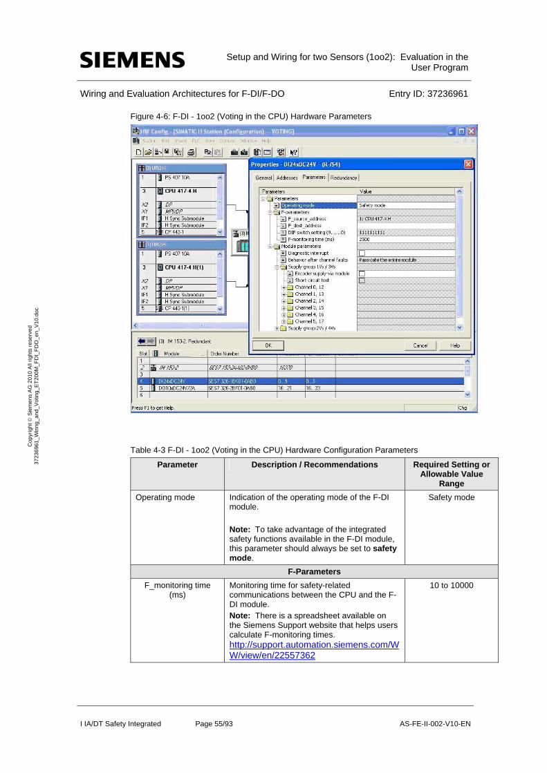
Setup and Wiring for two Sensors (1oo2): Evaluation in the
User Program
Wiring and Evaluation Architectures for F-DI/F-DO Entry ID: 37236961
I IA/DT Safety Integrated Page 55/93 AS-FE-II-002-V10-EN
Co
pyr
igh
t S
iem
en
s A
G 2
01
0 A
ll rig
hts
re
serv
ed
3
723
696
1_
Wiri
ng_
and
_V
otin
g_E
T2
00M
_F
DI_
FD
O_
en_
V1
0.d
oc
Figure 4-6: F-DI - 1oo2 (Voting in the CPU) Hardware Parameters
Table 4-3 F-DI - 1oo2 (Voting in the CPU) Hardware Configuration Parameters
Parameter Description / Recommendations Required Setting or Allowable Value
Range
Operating mode Indication of the operating mode of the F-DI module. Note: To take advantage of the integrated safety functions available in the F-DI module, this parameter should always be set to safety mode.
Safety mode
F-Parameters
F_monitoring time (ms)
Monitoring time for safety-related communications between the CPU and the F-DI module. Note: There is a spreadsheet available on the Siemens Support website that helps users calculate F-monitoring times. http://support.automation.siemens.com/WW/view/en/22557362
10 to 10000

Setup and Wiring for two Sensors (1oo2): Evaluation in the
User Program
Wiring and Evaluation Architectures for F-DI/F-DO Entry ID: 37236961
I IA/DT Safety Integrated Page 56/93 AS-FE-II-002-V10-EN
Co
pyr
igh
t S
iem
en
s A
G 2
01
0 A
ll rig
hts
re
serv
ed
3
723
696
1_
Wiri
ng_
and
_V
otin
g_E
T2
00M
_F
DI_
FD
O_
en_
V1
0.d
oc
Parameter Description / Recommendations Required Setting or Allowable Value
Range
Module Parameters
Diagnostic interrupt Diagnostic interrupt capability for the F-DI module. A diagnostic interrupt is triggered by various error events that the F-DI module can detect. These events are then made available to the CPU. Note: Once the diagnostic interrupt is enabled on the module-level, individual diagnostic events must be selected on the channel-level. The Diagnostic interrupt parameter must be enabled for all connected channels of failsafe modules.
Enable/Disable
Module Parameters for a Supply Group
Sensor supply via module
Selection for whether or not the sensor power is supplied by the F-DI module. Note: This option must be enabled in order to enable the short-circuit diagnostic (see below).
Enable/Disable
Short-circuit test Selection for whether or not short-circuit detection is enabled for the F-DI module. Note: This option is only useful if using simple switches that do not have their own power supply. The short-circuit test deactivates the sensor supply for short periods.
Enable/Disable
Channel/Channel Pair Parameters
Activated Selection for whether or not the channel/channel pair is enabled for signal processing in the safety program.
Enable/Disable
Evaluation of the sensors
Indication of the channel voting type. Note: For an F-DI module with 1oo2 voting in the CPU (not the signal module), this parameter should always be set to 1oo1.
Within the F-DI module itself, each of the two sensors is evaluated as a 1oo1 signal.
Within the CPU logic, the actual 1oo2 voting occurs.
1oo1
Type of sensor interconnection
Indication of the sensor indication (1 channel, 2 channels, etc). Note: With "1oo1 evaluation", the type of sensor is fixed and set to 1 channel.
1 channel
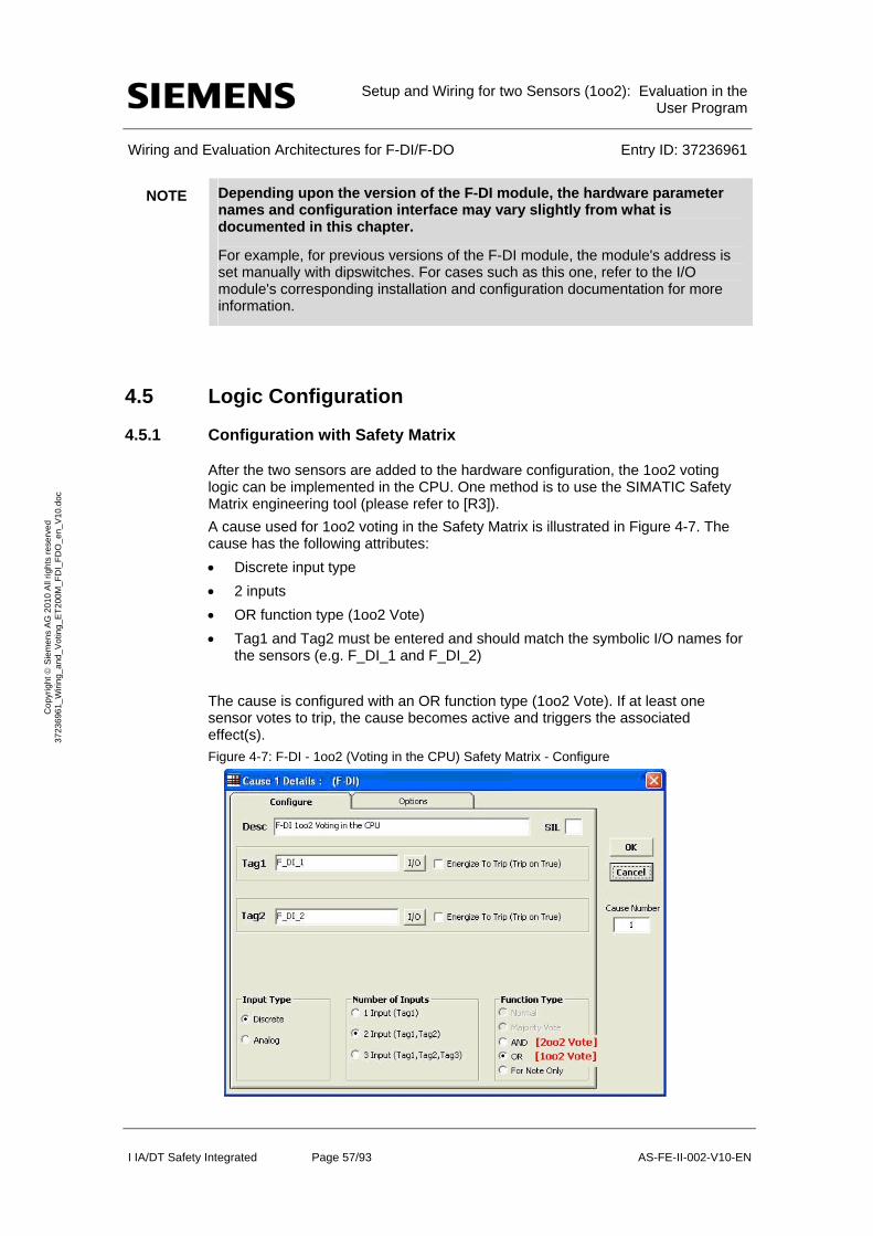
Setup and Wiring for two Sensors (1oo2): Evaluation in the
User Program
Wiring and Evaluation Architectures for F-DI/F-DO Entry ID: 37236961
I IA/DT Safety Integrated Page 57/93 AS-FE-II-002-V10-EN
Co
pyr
igh
t S
iem
en
s A
G 2
01
0 A
ll rig
hts
re
serv
ed
3
723
696
1_
Wiri
ng_
and
_V
otin
g_E
T2
00M
_F
DI_
FD
O_
en_
V1
0.d
oc
NOTE Depending upon the version of the F-DI module, the hardware parameter names and configuration interface may vary slightly from what is documented in this chapter.
For example, for previous versions of the F-DI module, the module's address is set manually with dipswitches. For cases such as this one, refer to the I/O module's corresponding installation and configuration documentation for more information.
4.5 Logic Configuration
4.5.1 Configuration with Safety Matrix
After the two sensors are added to the hardware configuration, the 1oo2 voting logic can be implemented in the CPU. One method is to use the SIMATIC Safety Matrix engineering tool (please refer to [R3]).
A cause used for 1oo2 voting in the Safety Matrix is illustrated in Figure 4-7. The cause has the following attributes:
Discrete input type
2 inputs
OR function type (1oo2 Vote)
Tag1 and Tag2 must be entered and should match the symbolic I/O names for the sensors (e.g. F_DI_1 and F_DI_2)
The cause is configured with an OR function type (1oo2 Vote). If at least one sensor votes to trip, the cause becomes active and triggers the associated effect(s).
Figure 4-7: F-DI - 1oo2 (Voting in the CPU) Safety Matrix - Configure
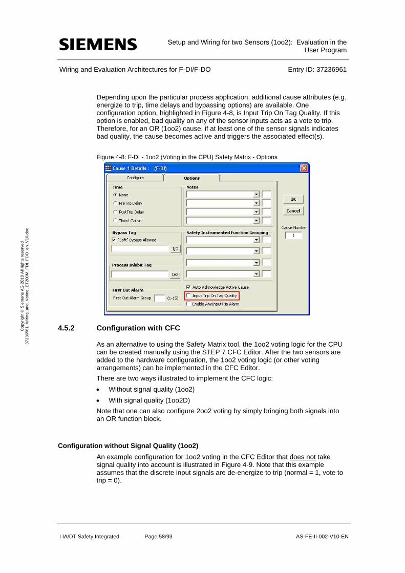
Setup and Wiring for two Sensors (1oo2): Evaluation in the
User Program
Wiring and Evaluation Architectures for F-DI/F-DO Entry ID: 37236961
I IA/DT Safety Integrated Page 58/93 AS-FE-II-002-V10-EN
Co
pyr
igh
t S
iem
en
s A
G 2
01
0 A
ll rig
hts
re
serv
ed
3
723
696
1_
Wiri
ng_
and
_V
otin
g_E
T2
00M
_F
DI_
FD
O_
en_
V1
0.d
oc
Depending upon the particular process application, additional cause attributes (e.g. energize to trip, time delays and bypassing options) are available. One configuration option, highlighted in Figure 4-8, is Input Trip On Tag Quality. If this option is enabled, bad quality on any of the sensor inputs acts as a vote to trip. Therefore, for an OR (1oo2) cause, if at least one of the sensor signals indicates bad quality, the cause becomes active and triggers the associated effect(s).
Figure 4-8: F-DI - 1oo2 (Voting in the CPU) Safety Matrix - Options
4.5.2 Configuration with CFC
As an alternative to using the Safety Matrix tool, the 1oo2 voting logic for the CPU can be created manually using the STEP 7 CFC Editor. After the two sensors are added to the hardware configuration, the 1oo2 voting logic (or other voting arrangements) can be implemented in the CFC Editor.
There are two ways illustrated to implement the CFC logic:
Without signal quality (1oo2)
With signal quality (1oo2D)
Note that one can also configure 2oo2 voting by simply bringing both signals into an OR function block.
Configuration without Signal Quality (1oo2)
An example configuration for 1oo2 voting in the CFC Editor that does not take signal quality into account is illustrated in Figure 4-9. Note that this example assumes that the discrete input signals are de-energize to trip (normal = 1, vote to trip = 0).
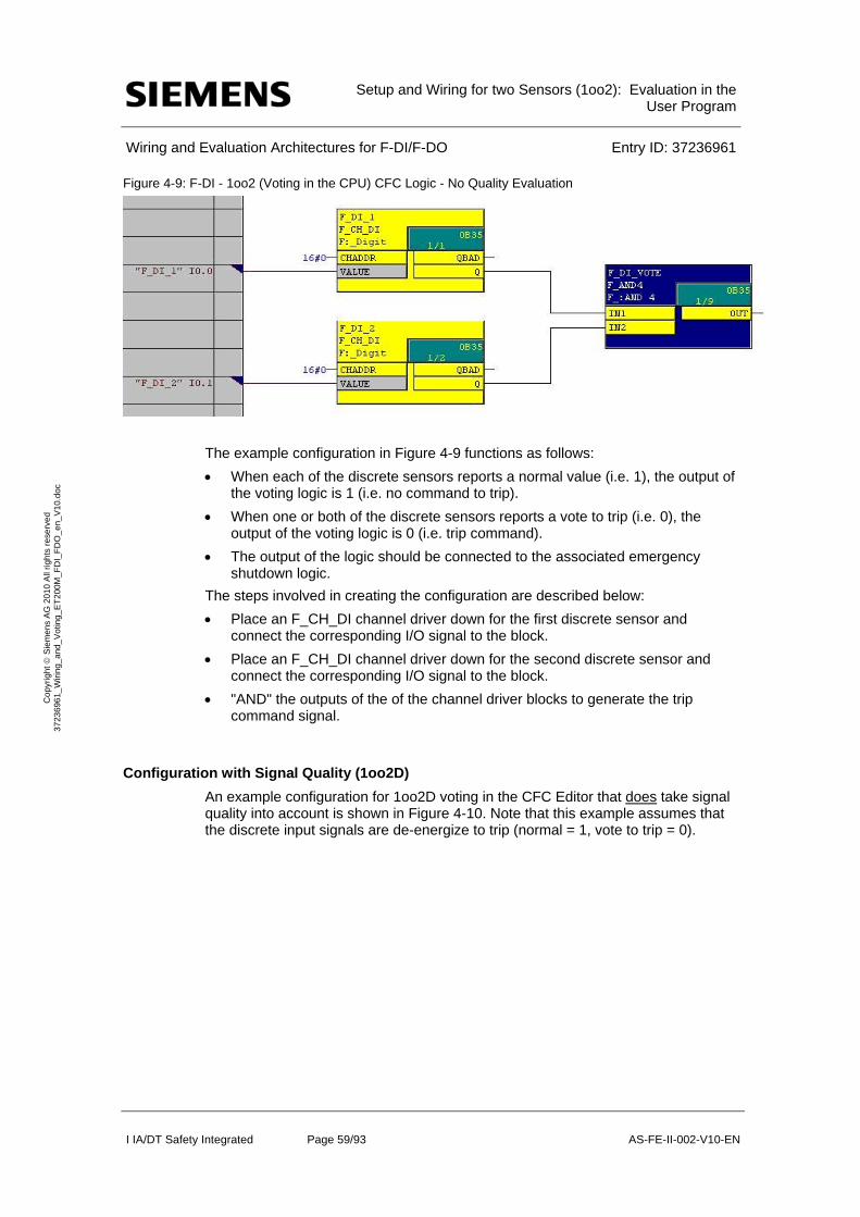
Setup and Wiring for two Sensors (1oo2): Evaluation in the
User Program
Wiring and Evaluation Architectures for F-DI/F-DO Entry ID: 37236961
I IA/DT Safety Integrated Page 59/93 AS-FE-II-002-V10-EN
Co
pyr
igh
t S
iem
en
s A
G 2
01
0 A
ll rig
hts
re
serv
ed
3
723
696
1_
Wiri
ng_
and
_V
otin
g_E
T2
00M
_F
DI_
FD
O_
en_
V1
0.d
oc
Figure 4-9: F-DI - 1oo2 (Voting in the CPU) CFC Logic - No Quality Evaluation
The example configuration in Figure 4-9 functions as follows:
When each of the discrete sensors reports a normal value (i.e. 1), the output of the voting logic is 1 (i.e. no command to trip).
When one or both of the discrete sensors reports a vote to trip (i.e. 0), the output of the voting logic is 0 (i.e. trip command).
The output of the logic should be connected to the associated emergency shutdown logic.
The steps involved in creating the configuration are described below:
Place an F_CH_DI channel driver down for the first discrete sensor and connect the corresponding I/O signal to the block.
Place an F_CH_DI channel driver down for the second discrete sensor and connect the corresponding I/O signal to the block.
"AND" the outputs of the of the channel driver blocks to generate the trip command signal.
Configuration with Signal Quality (1oo2D)
An example configuration for 1oo2D voting in the CFC Editor that does take signal quality into account is shown in Figure 4-10. Note that this example assumes that the discrete input signals are de-energize to trip (normal = 1, vote to trip = 0).
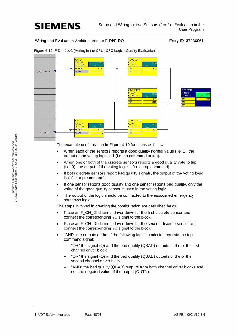
Setup and Wiring for two Sensors (1oo2): Evaluation in the
User Program
Wiring and Evaluation Architectures for F-DI/F-DO Entry ID: 37236961
I IA/DT Safety Integrated Page 60/93 AS-FE-II-002-V10-EN
Co
pyr
igh
t S
iem
en
s A
G 2
01
0 A
ll rig
hts
re
serv
ed
3
723
696
1_
Wiri
ng_
and
_V
otin
g_E
T2
00M
_F
DI_
FD
O_
en_
V1
0.d
oc
Figure 4-10: F-DI - 1oo2 (Voting in the CPU) CFC Logic - Quality Evaluation
The example configuration in Figure 4-10 functions as follows:
When each of the sensors reports a good quality normal value (i.e. 1), the output of the voting logic is 1 (i.e. no command to trip).
When one or both of the discrete sensors reports a good quality vote to trip (i.e. 0), the output of the voting logic is 0 (i.e. trip command).
If both discrete sensors report bad quality signals, the output of the voting logic is 0 (i.e. trip command).
If one sensor reports good quality and one sensor reports bad quality, only the value of the good quality sensor is used in the voting logic.
The output of the logic should be connected to the associated emergency shutdown logic.
The steps involved in creating the configuration are described below:
Place an F_CH_DI channel driver down for the first discrete sensor and connect the corresponding I/O signal to the block.
Place an F_CH_DI channel driver down for the second discrete sensor and connect the corresponding I/O signal to the block.
"AND" the outputs of the of the following logic checks to generate the trip command signal:
– "OR" the signal (Q) and the bad quality (QBAD) outputs of the of the first channel driver block.
– "OR" the signal (Q) and the bad quality (QBAD) outputs of the of the second channel driver block.
– "AND" the bad quality (QBAD) outputs from both channel driver blocks and use the negated value of the output (OUTN).
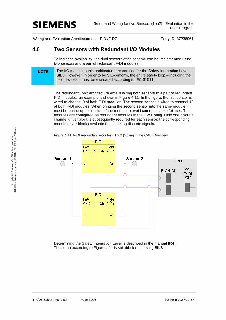
Setup and Wiring for two Sensors (1oo2): Evaluation in the
User Program
Wiring and Evaluation Architectures for F-DI/F-DO Entry ID: 37236961
I IA/DT Safety Integrated Page 61/93 AS-FE-II-002-V10-EN
Co
pyr
igh
t S
iem
en
s A
G 2
01
0 A
ll rig
hts
re
serv
ed
3
723
696
1_
Wiri
ng_
and
_V
otin
g_E
T2
00M
_F
DI_
FD
O_
en_
V1
0.d
oc
4.6 Two Sensors with Redundant I/O Modules
To increase availability, the dual sensor voting scheme can be implemented using two sensors and a pair of redundant F-DI modules.
NOTE The I/O module in this architecture are certified for the Safety Integration Level SIL3. However, in order to be SIL-conform, the entire safety loop – including the field devices – must be evaluated according to IEC 61511.
The redundant 1oo2 architecture entails wiring both sensors to a pair of redundant F-DI modules; an example is shown in Figure 4-11. In the figure, the first sensor is wired to channel 0 of both F-DI modules. The second sensor is wired to channel 12 of both F-DI modules. When bringing the second sensor into the same module, it must be on the opposite side of the module to avoid common cause failures. The modules are configured as redundant modules in the HW Config. Only one discrete channel driver block is subsequently required for each sensor; the corresponding module driver blocks evaluate the incoming discrete signals.
Figure 4-11: F-DI Redundant Modules - 1oo2 (Voting in the CPU) Overview
Determining the Safety Integration Level is described in the manual [R4]. The setup according to Figure 4-11 is suitable for achieving SIL3.

Setup and Wiring for two Sensors (1oo2): Evaluation in the
User Program
Wiring and Evaluation Architectures for F-DI/F-DO Entry ID: 37236961
I IA/DT Safety Integrated Page 62/93 AS-FE-II-002-V10-EN
Co
pyr
igh
t S
iem
en
s A
G 2
01
0 A
ll rig
hts
re
serv
ed
3
723
696
1_
Wiri
ng_
and
_V
otin
g_E
T2
00M
_F
DI_
FD
O_
en_
V1
0.d
oc
The following table shows when an error reaction function is triggered.
Table 4-4: Failure types for SIL 3 Logic
Component has failed ?
Sensor 1 Sensor 2 F-DI 1 F-DI 2
Error reaction function has
been triggered?
no no no X no
no no X no no
yes X X X yes
X yes X X yes
X X yes yes yes
If a sensor or both F-DI fail, the error reaction function provides the safety function (through the failsafe system).
NOTE The redundancy does not increase the Safety Integration Level.
4.6.1 Calculating the PFD
The PFD value (Probability of Failure on Demand) describes the failure probability of the failsafe function.
Calculation formula of the PFD
The PFD value for this wiring and evaluation architecture is calculated using the formula below:
PFD(1oo2) = PFDSensor + 2 PFDF-DI + PFDCPU
The PFDF-DI and PFDCPU values are available in Chapter 6.
For a 1oo2 sensor the PFDSensor value is calculated using the following formulafn :
2 2
1 2 3 2 DU I I
oo DU
T TPFD
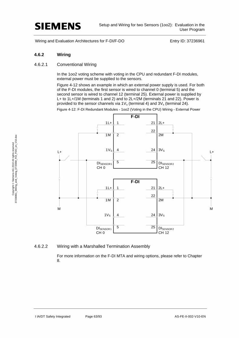
Setup and Wiring for two Sensors (1oo2): Evaluation in the
User Program
Wiring and Evaluation Architectures for F-DI/F-DO Entry ID: 37236961
I IA/DT Safety Integrated Page 63/93 AS-FE-II-002-V10-EN
Co
pyr
igh
t S
iem
en
s A
G 2
01
0 A
ll rig
hts
re
serv
ed
3
723
696
1_
Wiri
ng_
and
_V
otin
g_E
T2
00M
_F
DI_
FD
O_
en_
V1
0.d
oc
4.6.2 Wiring
4.6.2.1 Conventional Wiring
In the 1oo2 voting scheme with voting in the CPU and redundant F-DI modules, external power must be supplied to the sensors.
Figure 4-12 shows an example in which an external power supply is used. For both of the F-DI modules, the first sensor is wired to channel 0 (terminal 5) and the second sensor is wired to channel 12 (terminal 25). External power is supplied by L+ to 1L+/1M (terminals 1 and 2) and to 2L+/2M (terminals 21 and 22). Power is provided to the sensor channels via 1Vs (terminal 4) and 3Vs (terminal 24).
Figure 4-12: F-DI Redundant Modules - 1oo2 (Voting in the CPU) Wiring - External Power
4.6.2.2 Wiring with a Marshalled Termination Assembly
For more information on the F-DI MTA and wiring options, please refer to Chapter 8.
F-DI1L+
1M
1
2
1VS
DISENSOR1
CH 0
4
5
L +
M
F-DI1L+
1M
1
2
1VS 4
5DISENSOR1
CH 0
2L+
2M
21
22
3VS24
DISENSOR2
CH 12
25
2L+
2M
21
22
3VS24
DISENSOR2
CH 12
25
L+
M
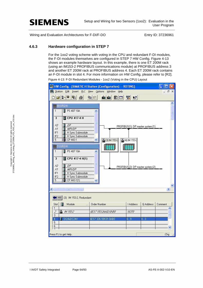
Setup and Wiring for two Sensors (1oo2): Evaluation in the
User Program
Wiring and Evaluation Architectures for F-DI/F-DO Entry ID: 37236961
I IA/DT Safety Integrated Page 64/93 AS-FE-II-002-V10-EN
Co
pyr
igh
t S
iem
en
s A
G 2
01
0 A
ll rig
hts
re
serv
ed
3
723
696
1_
Wiri
ng_
and
_V
otin
g_E
T2
00M
_F
DI_
FD
O_
en_
V1
0.d
oc
4.6.3 Hardware configuration in STEP 7
For the 1oo2 voting scheme with voting in the CPU and redundant F-DI modules, the F-DI modules themselves are configured in STEP 7 HW Config. Figure 4-13 shows an example hardware layout. In this example, there is one ET 200M rack (using an IM153-2 PROFIBUS communications module) at PROFIBUS address 3 and another ET 200M rack at PROFIBUS address 4. Each ET 200M rack contains an F-DI module in slot 4. For more information on HW Config, please refer to [R2].
Figure 4-13: F-DI Redundant Modules - 1oo2 (Voting in the CPU) Layout
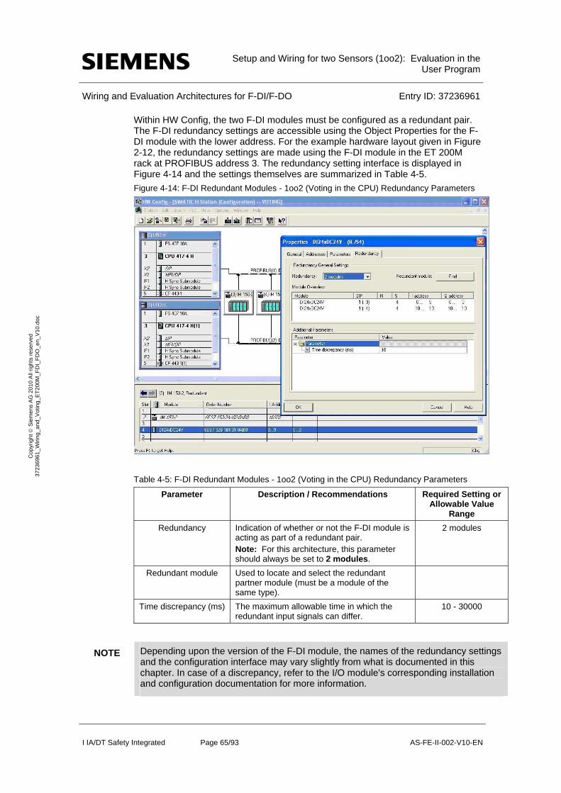
Setup and Wiring for two Sensors (1oo2): Evaluation in the
User Program
Wiring and Evaluation Architectures for F-DI/F-DO Entry ID: 37236961
I IA/DT Safety Integrated Page 65/93 AS-FE-II-002-V10-EN
Co
pyr
igh
t S
iem
en
s A
G 2
01
0 A
ll rig
hts
re
serv
ed
3
723
696
1_
Wiri
ng_
and
_V
otin
g_E
T2
00M
_F
DI_
FD
O_
en_
V1
0.d
oc
Within HW Config, the two F-DI modules must be configured as a redundant pair. The F-DI redundancy settings are accessible using the Object Properties for the F-DI module with the lower address. For the example hardware layout given in Figure 2-12, the redundancy settings are made using the F-DI module in the ET 200M rack at PROFIBUS address 3. The redundancy setting interface is displayed in Figure 4-14 and the settings themselves are summarized in Table 4-5.
Figure 4-14: F-DI Redundant Modules - 1oo2 (Voting in the CPU) Redundancy Parameters
Table 4-5: F-DI Redundant Modules - 1oo2 (Voting in the CPU) Redundancy Parameters
Parameter Description / Recommendations Required Setting or Allowable Value
Range
Redundancy Indication of whether or not the F-DI module is acting as part of a redundant pair. Note: For this architecture, this parameter should always be set to 2 modules.
2 modules
Redundant module Used to locate and select the redundant partner module (must be a module of the same type).
Time discrepancy (ms) The maximum allowable time in which the redundant input signals can differ.
10 - 30000
NOTE Depending upon the version of the F-DI module, the names of the redundancy settings and the configuration interface may vary slightly from what is documented in this chapter. In case of a discrepancy, refer to the I/O module's corresponding installation and configuration documentation for more information.

Setup and Wiring for two Sensors (1oo2): Evaluation in the
User Program
Wiring and Evaluation Architectures for F-DI/F-DO Entry ID: 37236961
I IA/DT Safety Integrated Page 66/93 AS-FE-II-002-V10-EN
Co
pyr
igh
t S
iem
en
s A
G 2
01
0 A
ll rig
hts
re
serv
ed
3
723
696
1_
Wiri
ng_
and
_V
otin
g_E
T2
00M
_F
DI_
FD
O_
en_
V1
0.d
oc
Once the redundancy settings are complete, the remainder of the hardware parameters for each of the redundant F-DI modules can be set using the guidelines provided back in Chapter 4.4 Hardware configuration in STEP 7 .
4.6.4 Logic Configuration
Though this voting scheme involves a pair of redundant F-DI modules, only two F_CH_DI channel driver function blocks are required in the logic configuration (one channel driver block for each of the 2 sensors). The channel driver blocks can be automatically added to the logic by the SIMATIC Safety Matrix or manually added and configured using the STEP7 CFC Editor. In both cases, the channel drivers should be connected to the discrete sensor signals from the F-DI module with the lower address.
The actual voting logic for the 1oo2 voting scheme with voting in the CPU and redundant F-DI modules is the same as that given back in Chapters 4.5 (Logic Configuration) and 4.5.2 (Configuration with CFC).
When the channel drivers have been configured and the voting logic is complete, the configuration is compiled. With the compilation option to generate module drivers enable, the compilation automatically adds and configures corresponding F_M_DI24 module drivers to the logic. Using information from HW Config, the module drivers are automatically configured to evaluate and handle the redundant discrete sensor signals.
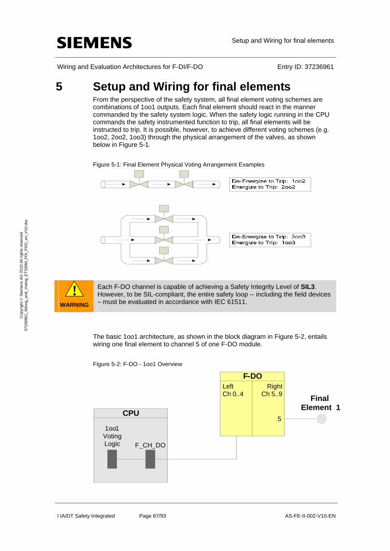
Setup and Wiring for final elements
Wiring and Evaluation Architectures for F-DI/F-DO Entry ID: 37236961
I IA/DT Safety Integrated Page 67/93 AS-FE-II-002-V10-EN
Co
pyr
igh
t S
iem
en
s A
G 2
01
0 A
ll rig
hts
re
serv
ed
3
723
696
1_
Wiri
ng_
and
_V
otin
g_E
T2
00M
_F
DI_
FD
O_
en_
V1
0.d
oc
5 Setup and Wiring for final elements From the perspective of the safety system, all final element voting schemes are combinations of 1oo1 outputs. Each final element should react in the manner commanded by the safety system logic. When the safety logic running in the CPU commands the safety instrumented function to trip, all final elements will be instructed to trip. It is possible, however, to achieve different voting schemes (e.g. 1oo2, 2oo2, 1oo3) through the physical arrangement of the valves, as shown below in Figure 5-1.
Figure 5-1: Final Element Physical Voting Arrangement Examples
!
WARNING
Each F-DO channel is capable of achieving a Safety Integrity Level of SIL3. However, to be SIL-compliant, the entire safety loop -- including the field devices – must be evaluated in accordance with IEC 61511.
The basic 1oo1 architecture, as shown in the block diagram in Figure 5-2, entails wiring one final element to channel 5 of one F-DO module.
Figure 5-2: F-DO - 1oo1 Overview
1oo1Voting Logic F _CH_ DO
CPU
LeftCh 0..4
F-DORight
Ch 5.. 9
5
Element 1Final

Setup and Wiring for final elements
Wiring and Evaluation Architectures for F-DI/F-DO Entry ID: 37236961
I IA/DT Safety Integrated Page 68/93 AS-FE-II-002-V10-EN
Co
pyr
igh
t S
iem
en
s A
G 2
01
0 A
ll rig
hts
re
serv
ed
3
723
696
1_
Wiri
ng_
and
_V
otin
g_E
T2
00M
_F
DI_
FD
O_
en_
V1
0.d
oc
5.1.1 Calculating the PFD
The PFD value (Probability of Failure on Demand) describes the failure probability of the safety function.
PFD calculation formula
The PFD value for this wiring and evaluation architecture is calculated using the formula below:
PFD(1oo1) = PFDFDO + PFDfinal element
NOTICE The PFDCPU wurde bei den Eingängen berücksichtigt und wird daher hier nicht mehr eingerechnet.
Zu der PFDCPU muss auch die PTE für PROFIsafe addiert werden.
The PFDF-DO value can be found in Chapter 6.
For a 1oo1 final element the PFDfinal element is calculated by this formula7:
5.2 Wiring
5.2.1 Conventional Wiring
The basic wiring F-DO wiring diagram for the 1oo1 voting scheme is illustrated in Figure 5-3. The final element is wired to channel 0 (terminal 3 – no series diode). Power is supplied to the backplane from 1L+/1M (terminals 21 and 22) and channel 0 is powered by 2L+/2M (terminals 17 and 19).
7 The formula is taken out of IEC61508, IEC 61511 and VDI 2180 Sheet 4
1 1 2 I
oo DU
TPFD
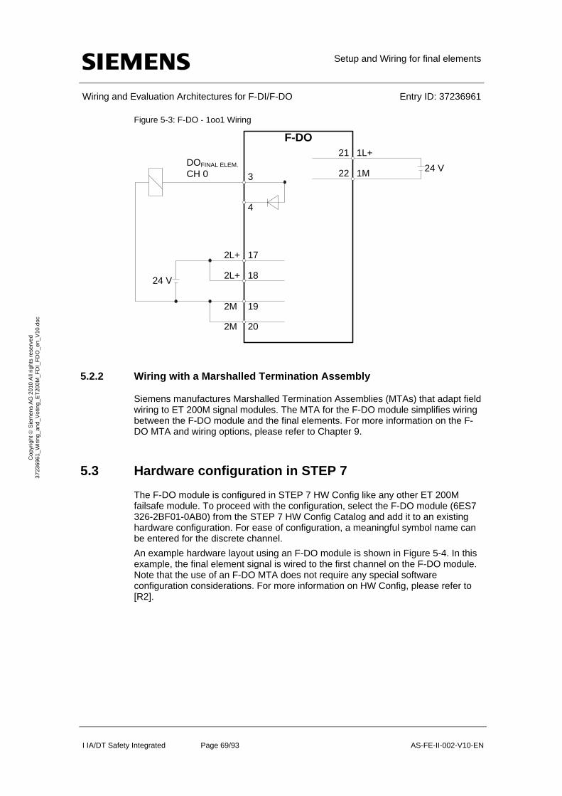
Setup and Wiring for final elements
Wiring and Evaluation Architectures for F-DI/F-DO Entry ID: 37236961
I IA/DT Safety Integrated Page 69/93 AS-FE-II-002-V10-EN
Co
pyr
igh
t S
iem
en
s A
G 2
01
0 A
ll rig
hts
re
serv
ed
3
723
696
1_
Wiri
ng_
and
_V
otin
g_E
T2
00M
_F
DI_
FD
O_
en_
V1
0.d
oc
Figure 5-3: F-DO - 1oo1 Wiring
F-DO
DOFINAL ELEM.
CH 0 3
4
1L+
1M
21
24 V22
2L+
2M
17
19
24 V 2L+ 18
2M 20
5.2.2 Wiring with a Marshalled Termination Assembly
Siemens manufactures Marshalled Termination Assemblies (MTAs) that adapt field wiring to ET 200M signal modules. The MTA for the F-DO module simplifies wiring between the F-DO module and the final elements. For more information on the F-DO MTA and wiring options, please refer to Chapter 9.
5.3 Hardware configuration in STEP 7
The F-DO module is configured in STEP 7 HW Config like any other ET 200M failsafe module. To proceed with the configuration, select the F-DO module (6ES7 326-2BF01-0AB0) from the STEP 7 HW Config Catalog and add it to an existing hardware configuration. For ease of configuration, a meaningful symbol name can be entered for the discrete channel.
An example hardware layout using an F-DO module is shown in Figure 5-4. In this example, the final element signal is wired to the first channel on the F-DO module. Note that the use of an F-DO MTA does not require any special software configuration considerations. For more information on HW Config, please refer to [R2].
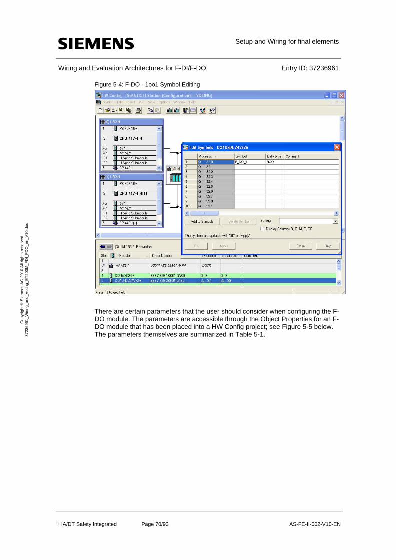
Setup and Wiring for final elements
Wiring and Evaluation Architectures for F-DI/F-DO Entry ID: 37236961
I IA/DT Safety Integrated Page 70/93 AS-FE-II-002-V10-EN
Co
pyr
igh
t S
iem
en
s A
G 2
01
0 A
ll rig
hts
re
serv
ed
3
723
696
1_
Wiri
ng_
and
_V
otin
g_E
T2
00M
_F
DI_
FD
O_
en_
V1
0.d
oc
Figure 5-4: F-DO - 1oo1 Symbol Editing
There are certain parameters that the user should consider when configuring the F-DO module. The parameters are accessible through the Object Properties for an F-DO module that has been placed into a HW Config project; see Figure 5-5 below. The parameters themselves are summarized in Table 5-1.
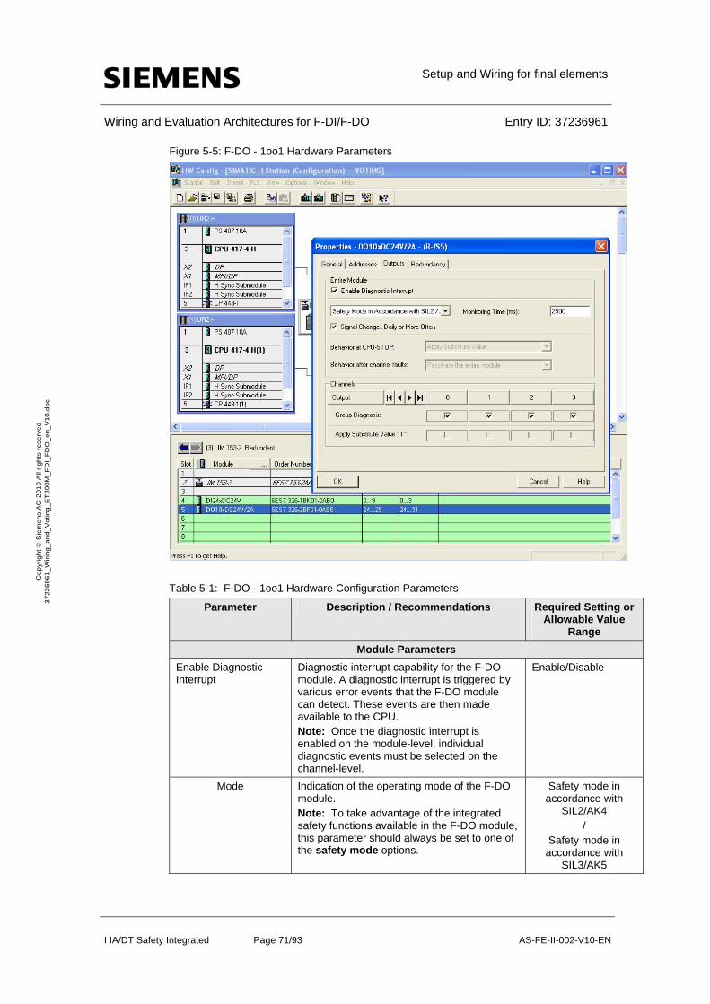
Setup and Wiring for final elements
Wiring and Evaluation Architectures for F-DI/F-DO Entry ID: 37236961
I IA/DT Safety Integrated Page 71/93 AS-FE-II-002-V10-EN
Co
pyr
igh
t S
iem
en
s A
G 2
01
0 A
ll rig
hts
re
serv
ed
3
723
696
1_
Wiri
ng_
and
_V
otin
g_E
T2
00M
_F
DI_
FD
O_
en_
V1
0.d
oc
Figure 5-5: F-DO - 1oo1 Hardware Parameters
Table 5-1: F-DO - 1oo1 Hardware Configuration Parameters
Parameter Description / Recommendations Required Setting or Allowable Value
Range
Module Parameters
Enable Diagnostic Interrupt
Diagnostic interrupt capability for the F-DO module. A diagnostic interrupt is triggered by various error events that the F-DO module can detect. These events are then made available to the CPU. Note: Once the diagnostic interrupt is enabled on the module-level, individual diagnostic events must be selected on the channel-level.
Enable/Disable
Mode Indication of the operating mode of the F-DO module. Note: To take advantage of the integrated safety functions available in the F-DO module, this parameter should always be set to one of the safety mode options.
Safety mode in accordance with
SIL2/AK4 /
Safety mode in accordance with
SIL3/AK5

Setup and Wiring for final elements
Wiring and Evaluation Architectures for F-DI/F-DO Entry ID: 37236961
I IA/DT Safety Integrated Page 72/93 AS-FE-II-002-V10-EN
Co
pyr
igh
t S
iem
en
s A
G 2
01
0 A
ll rig
hts
re
serv
ed
3
723
696
1_
Wiri
ng_
and
_V
otin
g_E
T2
00M
_F
DI_
FD
O_
en_
V1
0.d
oc
Parameter Description / Recommendations Required Setting or Allowable Value
Range
Monitoring Time (ms) Monitoring time for safety-related communications between the CPU and the F-DO module. Note: There is a spreadsheet available on the Siemens Support website that helps users calculate F-monitoring times.
http://support.automation.siemens.com/WW/view/en/22557362
10 to 10000
Signal Changes Daily or More Often
Selection for the type of test signal application:
To perform the test with "dark periods", enable the option
To perform the test with "light and dark periods", disable the option
Note: "Dark periods" occur during switch-off tests and complete bit pattern tests. While an F-DO output is active (output = 1), the output is switched off briefly (output = 0). "Light periods" occur during complete bit pattern tests. While an F-DO output is not active (output = 0), the output is switched on briefly (output = 1). For both "dark periods" and "light periods", if the actuator has a sufficiently slow response time, it will not react to the test.
Enable/Disable
Behavior at CPU-STOP
Selection only applies for modules in standard mode. For an F-DO module in safety mode, the value 0 is substituted for all of the module outputs if a CPU-STOP occurs. Indication of the sensor indication (1 channel, 2 channels, etc). Note: With "1oo1 evaluation", the type of sensor is fixed and set to 1 channel.
Channel Parameters Group Diagnosis Selection for whether or not a channel-specific
event triggers a fault reaction in the safety program. When enabled, channel-specific diagnostic messages (e.g. wire break, short circuit) are transmitted between the F-DO module and the CPU. Note: The Group Diagnosis parameter must be enabled for all connected channels of failsafe modules.
Enable/Disable
Apply Substitute Value "1"
Selection only applies for modules in standard mode. For an F-DO module in safety mode, the value 0 is substituted for all of the module outputs if a CPU-STOP occurs.
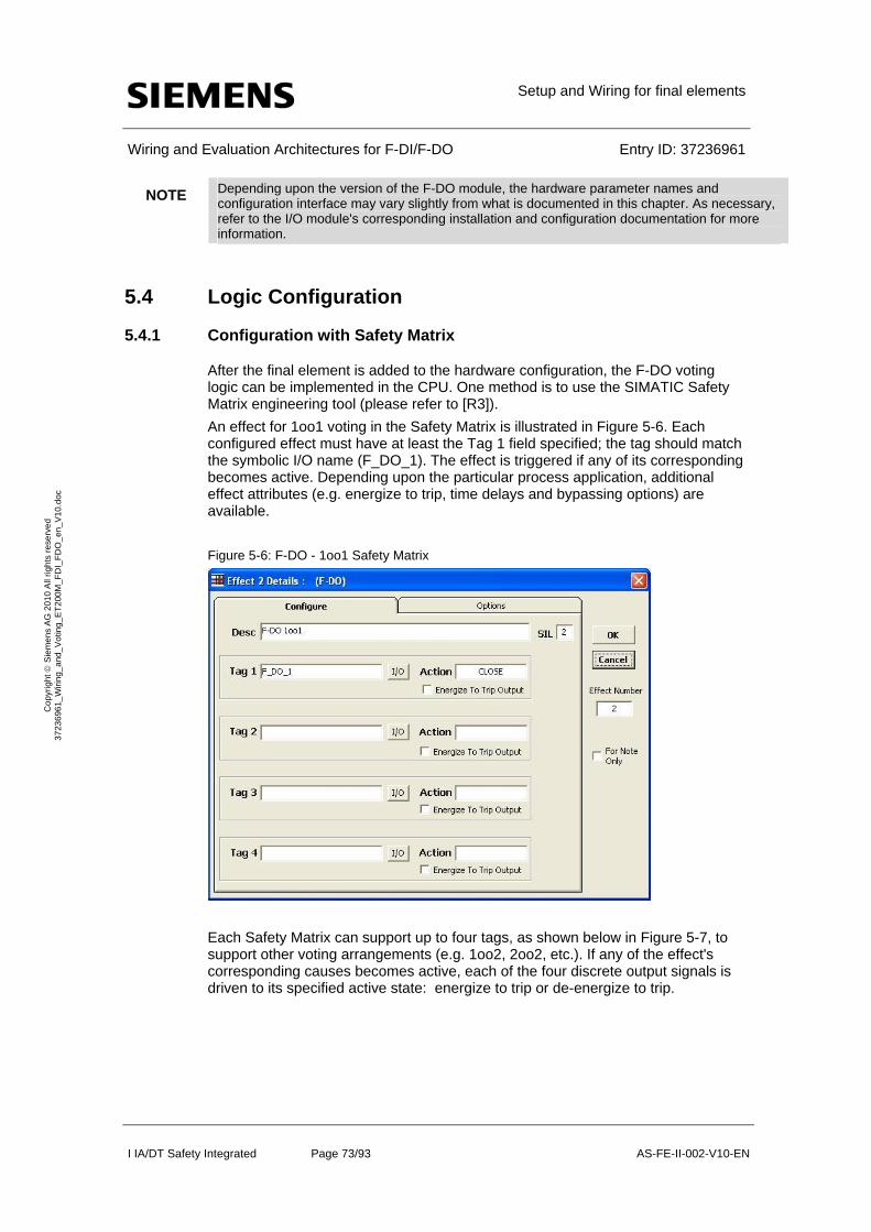
Setup and Wiring for final elements
Wiring and Evaluation Architectures for F-DI/F-DO Entry ID: 37236961
I IA/DT Safety Integrated Page 73/93 AS-FE-II-002-V10-EN
Co
pyr
igh
t S
iem
en
s A
G 2
01
0 A
ll rig
hts
re
serv
ed
3
723
696
1_
Wiri
ng_
and
_V
otin
g_E
T2
00M
_F
DI_
FD
O_
en_
V1
0.d
oc
NOTE Depending upon the version of the F-DO module, the hardware parameter names and configuration interface may vary slightly from what is documented in this chapter. As necessary, refer to the I/O module's corresponding installation and configuration documentation for more information.
5.4 Logic Configuration
5.4.1 Configuration with Safety Matrix
After the final element is added to the hardware configuration, the F-DO voting logic can be implemented in the CPU. One method is to use the SIMATIC Safety Matrix engineering tool (please refer to [R3]).
An effect for 1oo1 voting in the Safety Matrix is illustrated in Figure 5-6. Each configured effect must have at least the Tag 1 field specified; the tag should match the symbolic I/O name (F_DO_1). The effect is triggered if any of its corresponding becomes active. Depending upon the particular process application, additional effect attributes (e.g. energize to trip, time delays and bypassing options) are available.
Figure 5-6: F-DO - 1oo1 Safety Matrix
Each Safety Matrix can support up to four tags, as shown below in Figure 5-7, to support other voting arrangements (e.g. 1oo2, 2oo2, etc.). If any of the effect's corresponding causes becomes active, each of the four discrete output signals is driven to its specified active state: energize to trip or de-energize to trip.
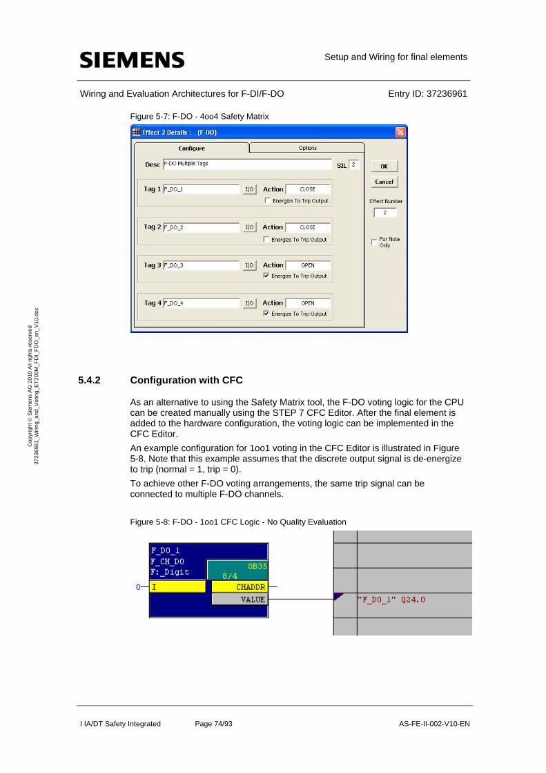
Setup and Wiring for final elements
Wiring and Evaluation Architectures for F-DI/F-DO Entry ID: 37236961
I IA/DT Safety Integrated Page 74/93 AS-FE-II-002-V10-EN
Co
pyr
igh
t S
iem
en
s A
G 2
01
0 A
ll rig
hts
re
serv
ed
3
723
696
1_
Wiri
ng_
and
_V
otin
g_E
T2
00M
_F
DI_
FD
O_
en_
V1
0.d
oc
Figure 5-7: F-DO - 4oo4 Safety Matrix
5.4.2 Configuration with CFC
As an alternative to using the Safety Matrix tool, the F-DO voting logic for the CPU can be created manually using the STEP 7 CFC Editor. After the final element is added to the hardware configuration, the voting logic can be implemented in the CFC Editor.
An example configuration for 1oo1 voting in the CFC Editor is illustrated in Figure 5-8. Note that this example assumes that the discrete output signal is de-energize to trip (normal = 1, trip = 0).
To achieve other F-DO voting arrangements, the same trip signal can be connected to multiple F-DO channels.
Figure 5-8: F-DO - 1oo1 CFC Logic - No Quality Evaluation
Setup and Wiring for final elements
Wiring and Evaluation Architectures for F-DI/F-DO Entry ID: 37236961
I IA/DT Safety Integrated Page 75/93 AS-FE-II-002-V10-EN
Co
pyr
igh
t S
iem
en
s A
G 2
01
0 A
ll rig
hts
re
serv
ed
3
723
696
1_
Wiri
ng_
and
_V
otin
g_E
T2
00M
_F
DI_
FD
O_
en_
V1
0.d
oc
The example configuration in Figure 5-8 functions as follows:
The input of the channel driver should be connected to the associated emergency shutdown logic.
When the shutdown logic reports a normal value (i.e. 1), the output to the final element is 1 (i.e. no trip).
When the shutdown logic reports a trip command (i.e. 0), the output to the final element is 0 (i.e. trip).
The steps involved in creating the configuration are described below:
Place an F_CH_DO channel driver down for the final element and connect the corresponding I/O signal to the block. The input of the channel driver should be connected to the safety voting logic.
5.5 Final Element Voting with Redundant I/O Modules
To increase the availability of the F-DO module, the single final element voting scheme can be implemented using a final element and a pair of redundant F-DO modules.
NOTE Each F-DO channel is capable of achieving a Safety Integrity Level of SIL3 regardless of module redundancy. However, to be SIL-compliant, the entire safety loop – including the field devices – must be evaluated in accordance with IEC 61511.
The redundant 1oo1 architecture entails wiring a single final element into a pair of redundant F-DO modules; a block diagram is shown in Figure 5-9. In the figure, the final element is wired to channel 5 of both F-DO modules. The modules are configured as redundant modules in HW Config. Only one discrete channel driver block is subsequently required; the corresponding module driver block handles the outgoing discrete signals.
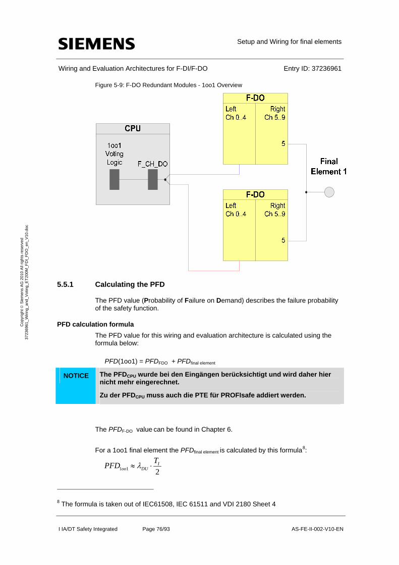
Setup and Wiring for final elements
Wiring and Evaluation Architectures for F-DI/F-DO Entry ID: 37236961
I IA/DT Safety Integrated Page 76/93 AS-FE-II-002-V10-EN
Co
pyr
igh
t S
iem
en
s A
G 2
01
0 A
ll rig
hts
re
serv
ed
3
723
696
1_
Wiri
ng_
and
_V
otin
g_E
T2
00M
_F
DI_
FD
O_
en_
V1
0.d
oc
Figure 5-9: F-DO Redundant Modules - 1oo1 Overview
5.5.1 Calculating the PFD
The PFD value (Probability of Failure on Demand) describes the failure probability of the safety function.
PFD calculation formula
The PFD value for this wiring and evaluation architecture is calculated using the formula below:
PFD(1oo1) = PFDFDO + PFDfinal element
NOTICE The PFDCPU wurde bei den Eingängen berücksichtigt und wird daher hier nicht mehr eingerechnet.
Zu der PFDCPU muss auch die PTE für PROFIsafe addiert werden.
The PFDF-DO value can be found in Chapter 6.
For a 1oo1 final element the PFDfinal element is calculated by this formula8:
8 The formula is taken out of IEC61508, IEC 61511 and VDI 2180 Sheet 4
1 1 2 I
oo DU
TPFD
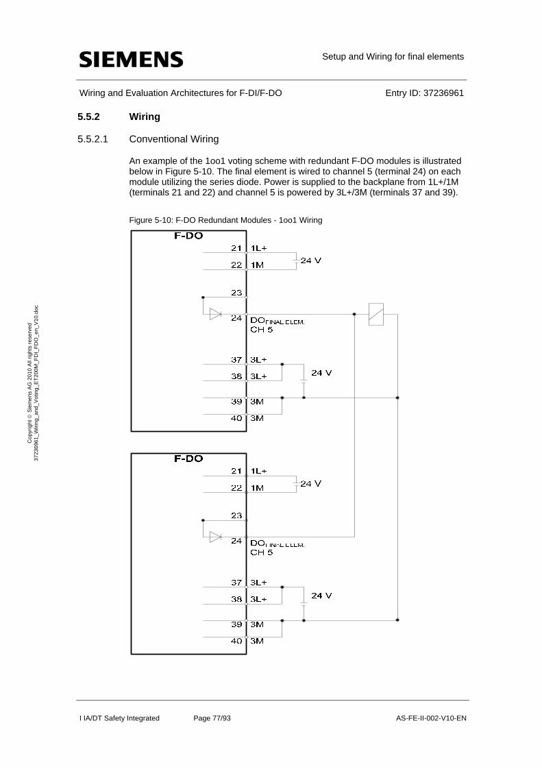
Setup and Wiring for final elements
Wiring and Evaluation Architectures for F-DI/F-DO Entry ID: 37236961
I IA/DT Safety Integrated Page 77/93 AS-FE-II-002-V10-EN
Co
pyr
igh
t S
iem
en
s A
G 2
01
0 A
ll rig
hts
re
serv
ed
3
723
696
1_
Wiri
ng_
and
_V
otin
g_E
T2
00M
_F
DI_
FD
O_
en_
V1
0.d
oc
5.5.2 Wiring
5.5.2.1 Conventional Wiring
An example of the 1oo1 voting scheme with redundant F-DO modules is illustrated below in Figure 5-10. The final element is wired to channel 5 (terminal 24) on each module utilizing the series diode. Power is supplied to the backplane from 1L+/1M (terminals 21 and 22) and channel 5 is powered by 3L+/3M (terminals 37 and 39).
Figure 5-10: F-DO Redundant Modules - 1oo1 Wiring
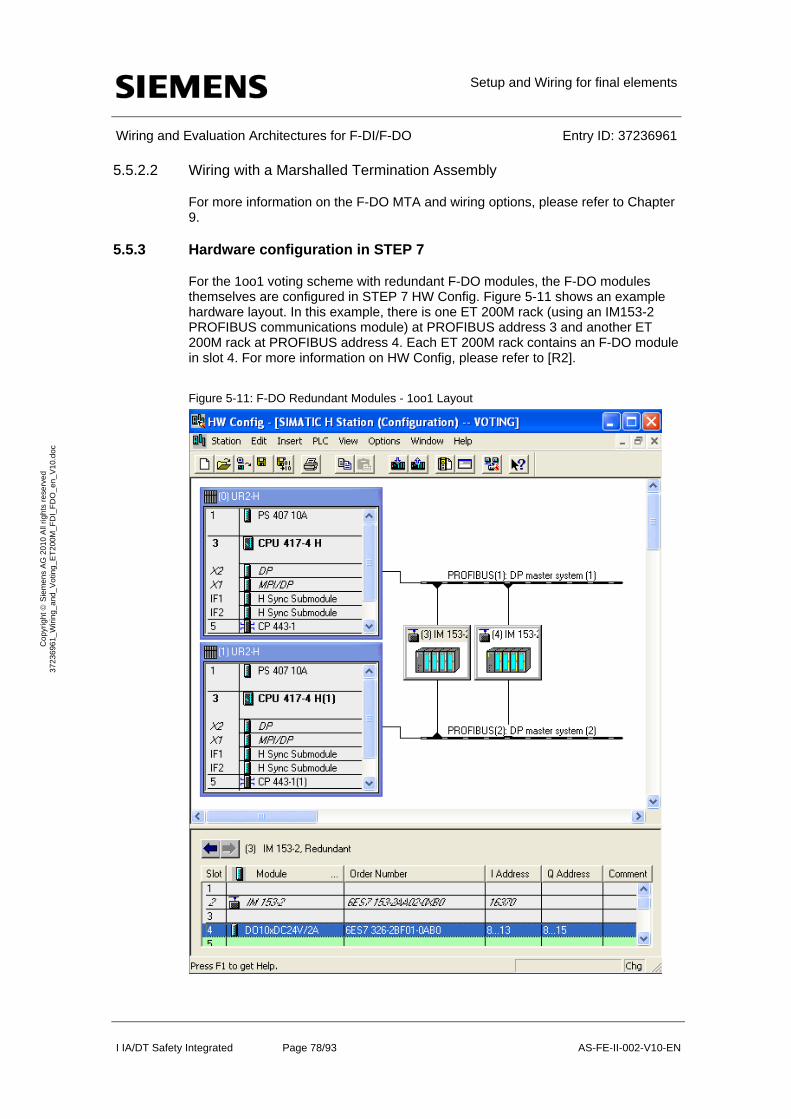
Setup and Wiring for final elements
Wiring and Evaluation Architectures for F-DI/F-DO Entry ID: 37236961
I IA/DT Safety Integrated Page 78/93 AS-FE-II-002-V10-EN
Co
pyr
igh
t S
iem
en
s A
G 2
01
0 A
ll rig
hts
re
serv
ed
3
723
696
1_
Wiri
ng_
and
_V
otin
g_E
T2
00M
_F
DI_
FD
O_
en_
V1
0.d
oc
5.5.2.2 Wiring with a Marshalled Termination Assembly
For more information on the F-DO MTA and wiring options, please refer to Chapter 9.
5.5.3 Hardware configuration in STEP 7
For the 1oo1 voting scheme with redundant F-DO modules, the F-DO modules themselves are configured in STEP 7 HW Config. Figure 5-11 shows an example hardware layout. In this example, there is one ET 200M rack (using an IM153-2 PROFIBUS communications module) at PROFIBUS address 3 and another ET 200M rack at PROFIBUS address 4. Each ET 200M rack contains an F-DO module in slot 4. For more information on HW Config, please refer to [R2].
Figure 5-11: F-DO Redundant Modules - 1oo1 Layout
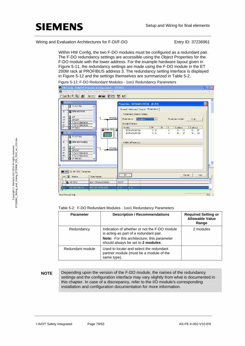
Setup and Wiring for final elements
Wiring and Evaluation Architectures for F-DI/F-DO Entry ID: 37236961
I IA/DT Safety Integrated Page 79/93 AS-FE-II-002-V10-EN
Co
pyr
igh
t S
iem
en
s A
G 2
01
0 A
ll rig
hts
re
serv
ed
3
723
696
1_
Wiri
ng_
and
_V
otin
g_E
T2
00M
_F
DI_
FD
O_
en_
V1
0.d
oc
Within HW Config, the two F-DO modules must be configured as a redundant pair. The F-DO redundancy settings are accessible using the Object Properties for the F-DO module with the lower address. For the example hardware layout given in Figure 5-11, the redundancy settings are made using the F-DO module in the ET 200M rack at PROFIBUS address 3. The redundancy setting interface is displayed in Figure 5-12 and the settings themselves are summarized in Table 5-2.
Figure 5-12: F-DO Redundant Modules - 1oo1 Redundancy Parameters
Table 5-2: F-DO Redundant Modules - 1oo1 Redundancy Parameters
Parameter Description / Recommendations Required Setting or Allowable Value
Range
Redundancy Indication of whether or not the F-DO module is acting as part of a redundant pair. Note: For this architecture, this parameter should always be set to 2 modules.
2 modules
Redundant module Used to locate and select the redundant partner module (must be a module of the same type).
NOTE Depending upon the version of the F-DO module, the names of the redundancy settings and the configuration interface may vary slightly from what is documented in this chapter. In case of a discrepancy, refer to the I/O module's corresponding installation and configuration documentation for more information.

Setup and Wiring for final elements
Wiring and Evaluation Architectures for F-DI/F-DO Entry ID: 37236961
I IA/DT Safety Integrated Page 80/93 AS-FE-II-002-V10-EN
Co
pyr
igh
t S
iem
en
s A
G 2
01
0 A
ll rig
hts
re
serv
ed
3
723
696
1_
Wiri
ng_
and
_V
otin
g_E
T2
00M
_F
DI_
FD
O_
en_
V1
0.d
oc
Once the redundancy settings are complete, the remainder of the hardware parameters for each of the redundant F-DO modules can be set using the guidelines provided back in Chapter 5.3 (Hardware configuration in STEP 7).
5.5.4 Logic Configuration
Though this voting scheme involves a pair of redundant F-DO modules, only one F_CH_DO channel driver function block is required in the logic configuration. The channel driver block can be automatically added to the logic by the SIMATIC Safety Matrix or manually added and configured using the STEP7 CFC Editor. In both cases, the channel driver should be connected to the discrete final element signal from the F-DO module with the lower address.
The actual voting logic for the 1oo1 voting scheme with redundant F-DO modules is the same as that given back in Chapters 5.4.1 (Configuration with Safety Matrix) and 5.4.2 (Configuration with CFC).
When the channel driver has been configured and the voting logic is complete, the configuration is compiled. With the compilation option to generate module drivers enable, the compilation automatically adds and configures a corresponding F_M_DO10 module driver to the logic. Using information from HW Config, the module driver is automatically configured to evaluate and handle the redundant discrete final element signals.
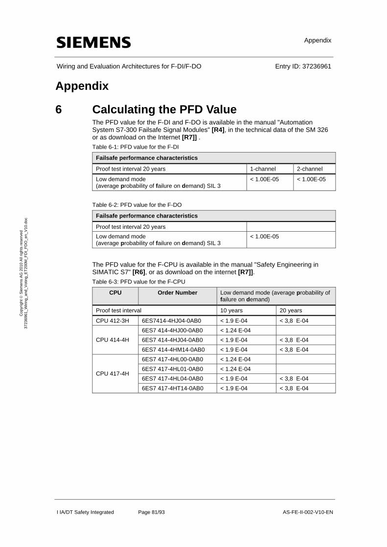
Appendix
Wiring and Evaluation Architectures for F-DI/F-DO Entry ID: 37236961
I IA/DT Safety Integrated Page 81/93 AS-FE-II-002-V10-EN
Co
pyr
igh
t S
iem
en
s A
G 2
01
0 A
ll rig
hts
re
serv
ed
3
723
696
1_
Wiri
ng_
and
_V
otin
g_E
T2
00M
_F
DI_
FD
O_
en_
V1
0.d
oc
Appendix
6 Calculating the PFD Value The PFD value for the F-DI and F-DO is available in the manual "Automation System S7-300 Failsafe Signal Modules" [R4], in the technical data of the SM 326 or as download on the Internet [R7]] .
Table 6-1: PFD value for the F-DI
Failsafe performance characteristics
Proof test interval 20 years 1-channel 2-channel
Low demand mode (average probability of failure on demand) SIL 3
< 1.00E-05 < 1.00E-05
Table 6-2: PFD value for the F-DO
Failsafe performance characteristics
Proof test interval 20 years
Low demand mode (average probability of failure on demand) SIL 3
< 1.00E-05
The PFD value for the F-CPU is available in the manual "Safety Engineering in SIMATIC S7" [R6], or as download on the internet [R7]].
Table 6-3: PFD value for the F-CPU
CPU Order Number Low demand mode (average probability of failure on demand)
Proof test interval 10 years 20 years
CPU 412-3H 6ES7414-4HJ04-0AB0 < 1.9 E-04 < 3,8 E-04
6ES7 414-4HJ00-0AB0 < 1.24 E-04
6ES7 414-4HJ04-0AB0 < 1.9 E-04 < 3,8 E-04 CPU 414-4H
6ES7 414-4HM14-0AB0 < 1.9 E-04 < 3,8 E-04
6ES7 417-4HL00-0AB0 < 1.24 E-04
6ES7 417-4HL01-0AB0 < 1.24 E-04
6ES7 417-4HL04-0AB0 < 1.9 E-04 < 3,8 E-04 CPU 417-4H
6ES7 417-4HT14-0AB0 < 1.9 E-04 < 3,8 E-04

Power and Grounding Recommendations
Wiring and Evaluation Architectures for F-DI/F-DO Entry ID: 37236961
I IA/DT Safety Integrated Page 82/93 AS-FE-II-002-V10-EN
Co
pyr
igh
t S
iem
en
s A
G 2
01
0 A
ll rig
hts
re
serv
ed
3
723
696
1_
Wiri
ng_
and
_V
otin
g_E
T2
00M
_F
DI_
FD
O_
en_
V1
0.d
oc
7 Power and Grounding Recommendations This chapter describes basic power and grounding guidelines for S7-400 F/FH systems. For more detailed information, please refer to [R4] and [R5].
7.1 Power
7.1.1 Power Feed Distribution
Power coming into a cabinet should land on a power distribution assembly installed as part of the system cabinet. Note that each power feed should have an independent distribution assembly. The power distribution assembly should have a set of terminals for incoming power with over-current protection. The power feed should provide a current limit of 20 mA for distribution. To increase system availability, the over-current protection should use some type of breaker device. To increase system reliability, a second power feed can be used (which will necessitate a second power feed distribution within the cabinet).
The power distribution should include a connection for each conductor on the power feed side: line, neutral/return and ground. The power feed ground terminal should be marked or color-coded so that it can be recognized as a safety ground connection. This ground terminal should provide a low impedance electrical connection to the enclosure. The ground terminal should be mechanically retained in order to ensure safety ground.
The power feed distribution should provide individual distribution terminals for connecting cabinet loads. The distribution terminals should be offered in a standard grouping with additional terminals for ground connections. The additional ground connections are required to ground the racks used for mounting system components.
7.1.2 System Power Distribution
System power distribution fans out cabinet-derived 24 VDC to loads within the cabinet. The system power distribution should provide multiple outputs with connections for each wire. System distribution should be isolated from any other ground reference – as should each load supplied with system power.
The system power distribution can be accomplished using discrete power supplies wired to the power feed distributions (described above in Chapter 7.1.1). Power supply integration is normally done on a per rack basis.
The power supply provides 24 VDC to the controllers and I/O modules. The power for the rack is carried via the backplane, as is the communications. When using isolating modules, the module backplane power and the communications are isolated from the field I/O. The isolation has two advantages:
Separation of control system operations from field operations
Isolation boundary for abatement of noise and lightning
Larger systems may utilize the system power distribution for field I/O while taking advantage of the packaged rack-based power of system components. This would be advantageous for system requiring field power beyond the normal supply range of Siemens power offerings. In such cases, the design should consider power architectures that feature redundancy. Redundant power architectures increase system reliability with online repair as long as common mode issues (like a one feeder circuit) are avoided.
Power and Grounding Recommendations
Wiring and Evaluation Architectures for F-DI/F-DO Entry ID: 37236961
I IA/DT Safety Integrated Page 83/93 AS-FE-II-002-V10-EN
Co
pyr
igh
t S
iem
en
s A
G 2
01
0 A
ll rig
hts
re
serv
ed
3
723
696
1_
Wiri
ng_
and
_V
otin
g_E
T2
00M
_F
DI_
FD
O_
en_
V1
0.d
oc
Other technologies can be used to increase system availability, such as uninterruptible power supplies (UPS) or DC backup systems. The use of such technologies does require understanding the system operation (e.g. power supply hold-up times, controller and I/O responses to power interruption, etc).
7.2 Grounding
7.2.1 Objectives
The "grounding" of a system has 3 basic objectives:
Personal safety
Protection against lightning or other sources of surge
Elimination of electrical interference
The prevention of unwanted effects from electrical interference is based upon the ‘linear ground path’ method. The flow of non-static electrical energy requires a loop where the sum of the currents into a node must equal zero. To avoid current flow (i.e. electrical noise), the system design should avoid the inclusion of loops. The concept of a linear path to ground (or a common reference point) involves a single conductive path that avoids the formation of any loops. From any given point in a system that has a ground connection, there should be only one path that can be traced from that point to ground.
The linear grounding method has limitations when applied to distributed process control systems. By definition, a distributed system in one in which components are geographically separated through a facility. In these types of architectures, the linear grounding method can be used effectively on system components referred to as equipment clusters (or islands of isolation). An equipment cluster can be defined as:
Having electrical isolation from the other system components
Having physical separation from other system clusters such that it is subject to locally derived electrical interference
In systems with equipment clusters, each cluster employs a locally-connected linear ground path for lightning and electrical noise reduction.
7.2.2 Implementation
The grounding recommendations provided in this chapter are specific to cabinets that include power supplies providing 24 VDC to the system components. Localizing power into the cabinets simplifies grounding rules. If power is shared between cabinets, the equipment should be located within close proximity to maintain a single ground reference point and connections. A single powered system should remain within a single cone of lightning protection (normally within a building or structure). Any locations outside a common lightning protection cone should use isolation techniques to reduce interference susceptibility. Typical isolation barriers include local power supplies, optical communications for data highways and isolated signal transmissions techniques (e.g. relay contacts, etc).
Safety Grounding
Cabinet design should allow for entry of power separate from other access openings. Power should be connected to a single distribution assembly within the cabinet. As part of the power distribution assembly, a cabinet grounding connection
Power and Grounding Recommendations
Wiring and Evaluation Architectures for F-DI/F-DO Entry ID: 37236961
I IA/DT Safety Integrated Page 84/93 AS-FE-II-002-V10-EN
Co
pyr
igh
t S
iem
en
s A
G 2
01
0 A
ll rig
hts
re
serv
ed
3
723
696
1_
Wiri
ng_
and
_V
otin
g_E
T2
00M
_F
DI_
FD
O_
en_
V1
0.d
oc
should be provided for safety ground. This connection should accommodate the required grounding conductor for proper operation of protective devices and personal safety. The cabinet grounding connection should be labeled or color-coded. If multiple power sources are used (e.g. for redundancy), independent distribution assemblies should be used and a separate cabinet grounding connection should be provided for each power source.
Shield Terminations
Field wiring shield terminations should be standard for I/O modules. The physical terminations for shielding should be provided at the termination location of the field signal wires, referred to as a shield collection. The shield collection should be isolated from mounting plates or rail assemblies within cabinets. Shield collections must accommodate a shield grounding conductor. The shield grounding conductor connects a shield collection to the local equal potential ground bar (LEPG).
The completion of the shield installation requires the connection of the LEPG bar to a ground reference. The preferred ground connection is to a ground electrode system also used for grounding the neutral conductors of the power system. Most industrial facilities support a single in-plant grounding system for interconnecting ‘locally’ derived ground system. The connection to the ground reference should be:
Low impedance (0.5 ohms or less)
As short a physical path as possible
Separate and independent from the safety ground connections required for personal protection
Note that the grounding of shields at one location provides protection from low frequency noise encountered in industrial environments. Care should be taken to ensure no other connections to ground occur for field signal shields.
DC Power Grounding
Typically, power supplies are installed in the cabinets to supply the operating voltage of 24 VDC. The power supplies have no connection to ground or power feeds. Depending on the user requirements, the system operates in either an ungrounded mode (floating) or is connected to a user-specified reference point.
System Setup
The S7-400 F/FH systems (including controllers and I/O) can be operated in a grounded or ungrounded mode. To accommodate both modes, the system design includes a jumper that provides a frame ground connection. When the jumper is removed, the power common is disconnected from the frame ground. Depending upon the product, the jumper is either part of the hardware module (see Figure 7-1) or the system backplane (see Figure 7-2).
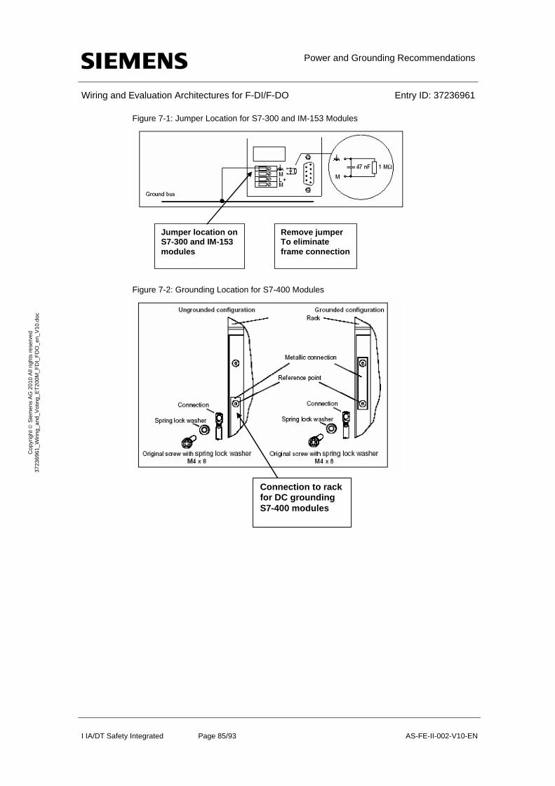
Power and Grounding Recommendations
Wiring and Evaluation Architectures for F-DI/F-DO Entry ID: 37236961
I IA/DT Safety Integrated Page 85/93 AS-FE-II-002-V10-EN
Co
pyr
igh
t S
iem
en
s A
G 2
01
0 A
ll rig
hts
re
serv
ed
3
723
696
1_
Wiri
ng_
and
_V
otin
g_E
T2
00M
_F
DI_
FD
O_
en_
V1
0.d
oc
Figure 7-1: Jumper Location for S7-300 and IM-153 Modules
Jumper location onS7-300 and IM-153 modules
Remove jumperTo eliminate frame connection
Figure 7-2: Grounding Location for S7-400 Modules
Connection to rackfor DC grounding S7-400 modules

F-DI Marshalled Termination Assemblies (MTAs)
Wiring and Evaluation Architectures for F-DI/F-DO Entry ID: 37236961
I IA/DT Safety Integrated Page 86/93 AS-FE-II-002-V10-EN
Co
pyr
igh
t S
iem
en
s A
G 2
01
0 A
ll rig
hts
re
serv
ed
3
723
696
1_
Wiri
ng_
and
_V
otin
g_E
T2
00M
_F
DI_
FD
O_
en_
V1
0.d
oc
8 F-DI Marshalled Termination Assemblies (MTAs) Siemens manufactures Marshalled Termination Assemblies (MTAs) that adapt field wiring to ET 200M signal modules. The MTA for the F-DI module simplifies wiring between the sensors and the F-DI module. The order number for the current version of the F-DI MTA is: 6ES7 650-1AK10-7XX0.
The F-DI MTA, shown in Figure 8-1, incorporates the following features:
Redundant power connections
LED indication of redundant power supply condition
Power monitor plug-in (optional)
Dual connectors for redundant signal module operation
Per module power fusing
LED indication of power to the field device on an individual channel basis
Per channel fusing of field power
Per channel disconnects
Shield connections available for channel cabling
Ground stud for connecting shield to earth ground
Pluggable power input and field terminations for easy maintenance
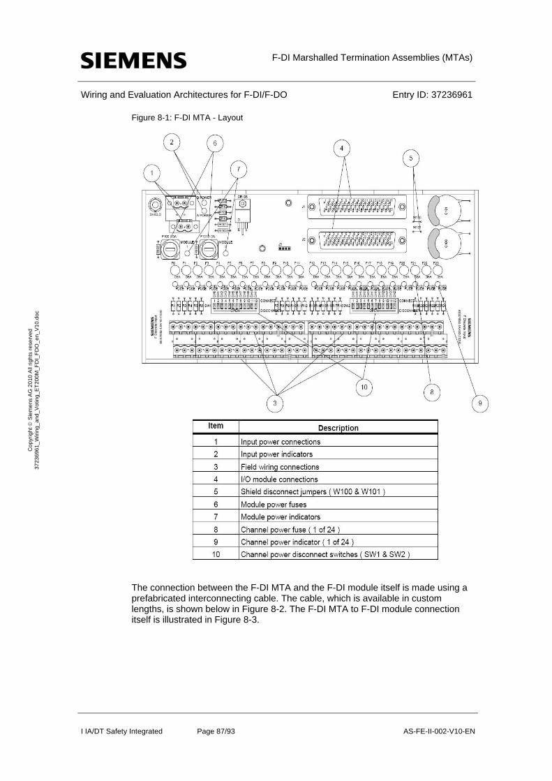
F-DI Marshalled Termination Assemblies (MTAs)
Wiring and Evaluation Architectures for F-DI/F-DO Entry ID: 37236961
I IA/DT Safety Integrated Page 87/93 AS-FE-II-002-V10-EN
Co
pyr
igh
t S
iem
en
s A
G 2
01
0 A
ll rig
hts
re
serv
ed
3
723
696
1_
Wiri
ng_
and
_V
otin
g_E
T2
00M
_F
DI_
FD
O_
en_
V1
0.d
oc
Figure 8-1: F-DI MTA - Layout
The connection between the F-DI MTA and the F-DI module itself is made using a prefabricated interconnecting cable. The cable, which is available in custom lengths, is shown below in Figure 8-2. The F-DI MTA to F-DI module connection itself is illustrated in Figure 8-3.
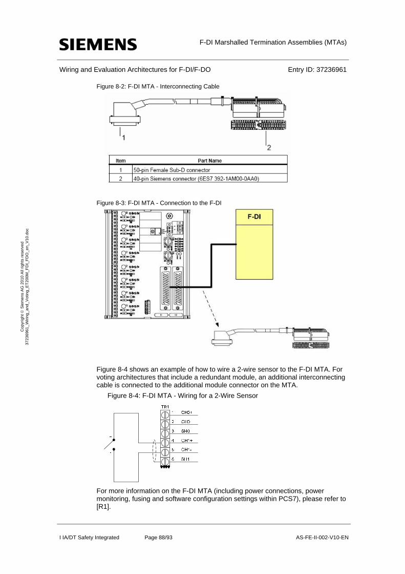
F-DI Marshalled Termination Assemblies (MTAs)
Wiring and Evaluation Architectures for F-DI/F-DO Entry ID: 37236961
I IA/DT Safety Integrated Page 88/93 AS-FE-II-002-V10-EN
Co
pyr
igh
t S
iem
en
s A
G 2
01
0 A
ll rig
hts
re
serv
ed
3
723
696
1_
Wiri
ng_
and
_V
otin
g_E
T2
00M
_F
DI_
FD
O_
en_
V1
0.d
oc
Figure 8-2: F-DI MTA - Interconnecting Cable
Figure 8-3: F-DI MTA - Connection to the F-DI
Figure 8-4 shows an example of how to wire a 2-wire sensor to the F-DI MTA. For voting architectures that include a redundant module, an additional interconnecting cable is connected to the additional module connector on the MTA.
Figure 8-4: F-DI MTA - Wiring for a 2-Wire Sensor
For more information on the F-DI MTA (including power connections, power monitoring, fusing and software configuration settings within PCS7), please refer to [R1].

F-DO Marshalled Termination Assemblies (MTAs)
Wiring and Evaluation Architectures for F-DI/F-DO Entry ID: 37236961
I IA/DT Safety Integrated Page 89/93 AS-FE-II-002-V10-EN
Co
pyr
igh
t S
iem
en
s A
G 2
01
0 A
ll rig
hts
re
serv
ed
3
723
696
1_
Wiri
ng_
and
_V
otin
g_E
T2
00M
_F
DI_
FD
O_
en_
V1
0.d
oc
9 F-DO Marshalled Termination Assemblies (MTAs) Siemens manufactures Marshalled Termination Assemblies (MTAs) that adapt field wiring to ET 200M signal modules. The MTA for the F-DO module simplifies wiring between the F-DO module and the final elements. The order number for the current version of the F-DO MTA is: 6ES7 650-1AL10-6XX0.
The F-DO MTA, shown in Figure 9-1, incorporates the following features:
Redundant power connections
LED indication of redundant power supply condition
Power monitor plug-in (optional)
Dual connectors for redundant signal module operation
Per module power fusing
Per channel fusing of field power
Shield connections available for channel cabling
Ground stud for connecting shield to earth ground
Pluggable power input and field terminations for easy maintenance
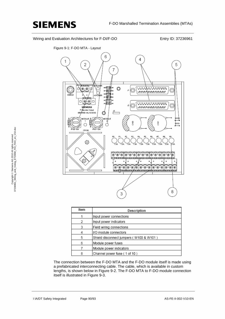
F-DO Marshalled Termination Assemblies (MTAs)
Wiring and Evaluation Architectures for F-DI/F-DO Entry ID: 37236961
I IA/DT Safety Integrated Page 90/93 AS-FE-II-002-V10-EN
Co
pyr
igh
t S
iem
en
s A
G 2
01
0 A
ll rig
hts
re
serv
ed
3
723
696
1_
Wiri
ng_
and
_V
otin
g_E
T2
00M
_F
DI_
FD
O_
en_
V1
0.d
oc
Figure 9-1: F-DO MTA - Layout
The connection between the F-DO MTA and the F-DO module itself is made using a prefabricated interconnecting cable. The cable, which is available in custom lengths, is shown below in Figure 9-2. The F-DO MTA to F-DO module connection itself is illustrated in Figure 9-3.
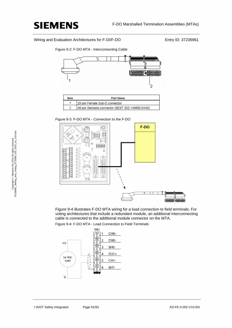
F-DO Marshalled Termination Assemblies (MTAs)
Wiring and Evaluation Architectures for F-DI/F-DO Entry ID: 37236961
I IA/DT Safety Integrated Page 91/93 AS-FE-II-002-V10-EN
Co
pyr
igh
t S
iem
en
s A
G 2
01
0 A
ll rig
hts
re
serv
ed
3
723
696
1_
Wiri
ng_
and
_V
otin
g_E
T2
00M
_F
DI_
FD
O_
en_
V1
0.d
oc
Figure 9-2: F-DO MTA - Interconnecting Cable
Figure 9-3: F-DO MTA - Connection to the F-DO
Figure 9-4 illustrates F-DO MTA wiring for a load connection to field terminals. For voting architectures that include a redundant module, an additional interconnecting cable is connected to the additional module connector on the MTA.
Figure 9-4: F-DO MTA - Load Connection to Field Terminals

F-DO Marshalled Termination Assemblies (MTAs)
Wiring and Evaluation Architectures for F-DI/F-DO Entry ID: 37236961
I IA/DT Safety Integrated Page 92/93 AS-FE-II-002-V10-EN
Co
pyr
igh
t S
iem
en
s A
G 2
01
0 A
ll rig
hts
re
serv
ed
3
723
696
1_
Wiri
ng_
and
_V
otin
g_E
T2
00M
_F
DI_
FD
O_
en_
V1
0.d
oc
For more information on the F-DO MTA (including power connections, power monitoring, fusing and software configuration settings within PCS7), please refer to [R1].

Bibliography
Wiring and Evaluation Architectures for F-DI/F-DO Entry ID: 37236961
I IA/DT Safety Integrated Page 93/93 AS-FE-II-002-V10-EN
Co
pyr
igh
t S
iem
en
s A
G 2
01
0 A
ll rig
hts
re
serv
ed
3
723
696
1_
Wiri
ng_
and
_V
otin
g_E
T2
00M
_F
DI_
FD
O_
en_
V1
0.d
oc
10 Bibliography [R1] Siemens SIMATIC Marshalled Termination Assemblies - ET 200M
Remote I/O Modules Manual, Edition 10/2008
http://support.automation.siemens.com/WW/view/en/22091986
[R2] Siemens SIMATIC Configuring Hardware and Communication Connections STEP 7 V5.4 Manual, Edition 03/2006
http://support.automation.siemens.com/WW/view/en/18652631
[R3] Siemens SIMATIC Safety Matrix User's Guide, Edition 03/2008
http://support.automation.siemens.com/WW/view/en/19056619
[R4] Siemens SIMATIC Automation System S7-300 Fail-Safe Signal Modules, Edition 02/2008
http://support.automation.siemens.com/WW/view/en/19026151
[R5] Siemens SIMATIC Automation System S7-400 Hardware and Installation Manual, Edition 11/2006
http://support.automation.siemens.com/WW/view/en/1117849
[R6] Siemens “Safety Engineering in SIMATIC S7” Manual, Edition 12/2008
http://support.automation.siemens.com/WW/view/en/12490443
[R7]] Which values can be used for F-CPUs and for products of the ET 200 family for PFD, PFH and the Proof Test Interval ?
http://support.automation.siemens.com/WW/view/en/27832836
11 History Table 11-1: History
Version Data Change
V1.0 01/2010 First issue