Embed Size (px)
Citation preview

SAFE SWITCHGEAR FOR COMPLEX AND CRITICAL APPLICATIONS
// Control Technology / Catalogue
Safety sensors / Magnetic safety sensors / Magnetic sensors

2

3
4 The company
PRODUCTS
8 Safety sensors
12 Series HS Si 414 Series BZ 16
14 Magnetic safety sensors
18 Series RC Si M3020 Series RC Si 5622 Safety relay module SRM 21 RT2
24 Magnetic sensors cylindrical form
28 Series RC 332 Series RC 834 Series RC 1036 Series RC 13,538 Series RC 1540 Series RC M2042 Series RC 2044 Series RC 2346 Series RC 3048 Series RC 60
52 Magnetic sensors rectangular form
54 Series RC 456 Series RC 558 Series RC 4060 Series RC 4262 Series RC 5064 Series RC 8066 Series RC 9068 Series RC 96
75 Appendix
75 Explanation of symbols
4
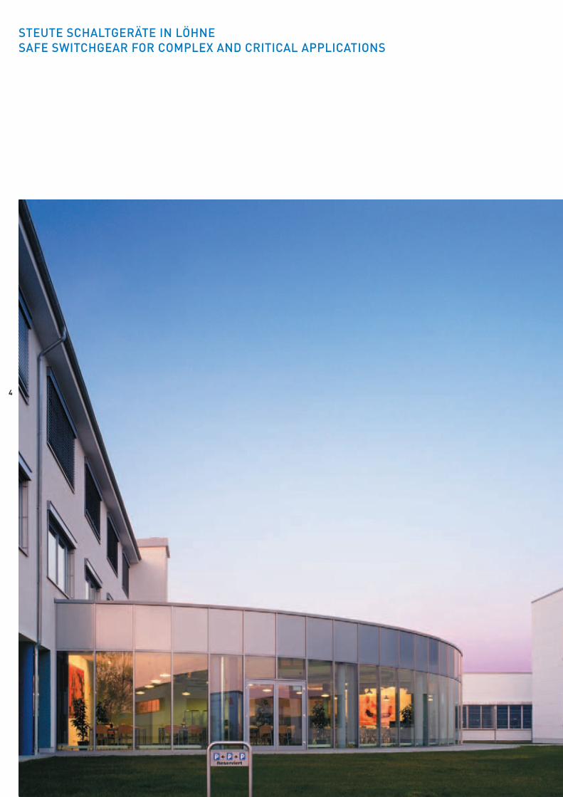
STEUTE SCHALTGERÄTE IN LÖHNESAFE SWITCHGEAR FOR COMPLEX AND CRITICAL APPLICATIONS

55
Our location: A good place to live and to work. Löhne, Westphalia,Germany. Embedded between the »Wiehengebirge« and the »Teuto-burger Wald«. This is the location of steute Schaltgeräte GmbH & Co.KG. Here, switchgear is designed and produced for explosion protec-tion, medical equipment and control technology.
Historians know our region as the area where the Battle of Varustook place in the year 9 AD. About 1700 years later, the Treaty of West-phalia marked the end of the Thirty Years’ War. Gourmets love West-phalian sausage, walkers the beautiful landscape. Briefly: it’s a goodplace to live. It’s also a good place to work. The industrial culture ofWestphalia is mostly characterised by SME companies; the region isalso the home of many hidden champions and world-market leaders,specialist machine and system manufacturers, as well as electronicand connecting technology.
This means we have many important suppliers, customers andpartners practically »on our doorstep«. And even so, our employeestravel a great deal all over the world. This is because renowned com-panies in all industrial markets use switchgear by steute when thefocus is on high quality and availability. And when they appreciate co-operating with suppliers who can adapt flexibly to their requests.

6

7
STEUTE SWITCHGEAR MEETS THE HIGHEST QUALITY REQUIREMENTS
Today, the company offers a homogenous product range, drawingon its wide know-how and characterised by a high degree of techno-logical synergy.
180 employees attentively develop and manufacture electricaland electronic components for high-standard and explosive safety ap-plications. These applications comply with established internationaldirectives, laws, standards and regulations. In this context, key signifi-cance is attributed to a close cooperation with technical certificationinstitutions.
With its high standards and specific orientation, steute lives andbreathes the following three QM systems:
- DIN EN ISO 9001: 2000- DIN EN ISO 13485: 2003- Certificate of Quality Assurance acknowledgement in accordance
with the 94/9/EC Directive (ATEX)
On the following pages you will find an overview of our compre-hensive range of safety, magnetic safety and magnetic sensors andtheir corresponding actuating magnets, each of which can be modi-fied in accordance with customer-specific requirements.
Talk to us. Let us help you find what you are looking for.The steute team.
9
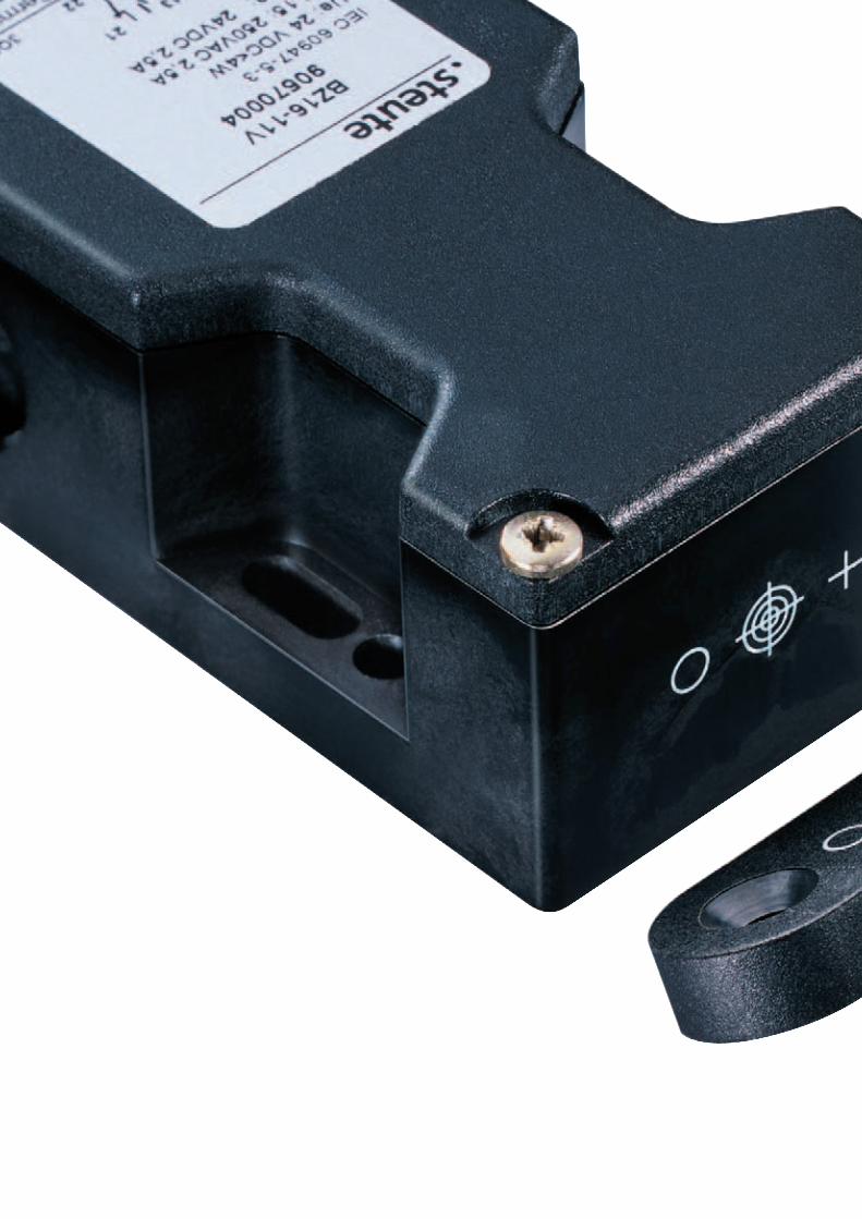
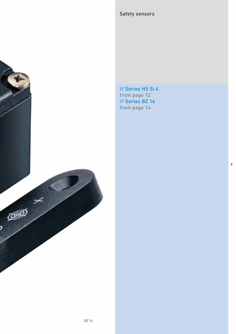
Safety sensors
// Series HS Si 4from page 12// Series BZ 16from page 14
BZ 16
10

1111
Safety sensors
ApplicationSafety sensors are suitable for the safeguarding of sliding, hinged
or removable protective doors that need to be closed to secure the re-quired operators’ safety. They are also applicable on profile sectionsand for retrofitting on existing equipment.
All presented safety sensors achieve, in combination with an ap-propriate safety relay module, Control Category 3 or 4 to EN 954-1.
Safety sensors are preferably applied as an alternative to mechani-cally operated limit switches in cases where unfavourable operatingconditions, such as high or low actuating speeds, large switching fre-quencies, extreme dirt or dust production, high humidity, chemical at-mospheres, highly fluctuating actuating distances, etc. occur. Even inthe presence of aggressive materials, as well as in the food processingindustry, safe switching is ensured through encapsulation of the con-tacts.
Design and operating principleThe safety sensors are actuated by a coded actuator without any
mechanical contact. The devices can be selected with one NC and oneNO contact or with two NC contacts.
All described safety sensors have a wiring compartment.The BZ 16 safety sensor is used in safety circuits for position moni-
toring of movable safety guards in accordance with EN 1088 andIEC/EN 60947-5-3. The entire system, consisting of the BZ 16 safetysensor (with integrated evaluation) and the BZ 16-B1 actuator, meetsthe requirements of the IEC/EN 60947-5-3 standard. The safety sen-sors are classified in level PDF-S to IEC/EN 60947-5-3.
The safety sensors achieve Control Category 3 or 4 to EN 954-1only in combination with a safety relay module series SRM. Technicaldetails regarding this safety relay module can be found in the »Mag-netic safety sensors« chapter.
All safety sensors described in this chapter bear the CE mark ac-cording to the Machinery Directive 98/37/EC.
On sliding doorsApplicationOn hinged doors
On removable doors
12
// HS SI 4 Technical data
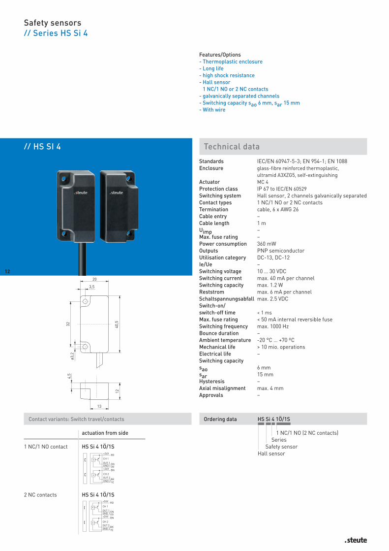
Safety sensors// Series HS Si 4
Features/Options - Thermoplastic enclosure- Long life- high shock resistance- Hall sensor
1 NC/1 NO or 2 NC contacts- galvanically separated channels- Switching capacity sao 6 mm, sar 15 mm- With wire
Standards IEC/EN 60947-5-3; EN 954-1; EN 1088Enclosure glass-fibre reinforced thermoplastic,
ultramid A3XZG5, self-extinguishing Actuator MC 4Protection class IP 67 to IEC/EN 60529Switching system Hall sensor, 2 channels galvanically separatedContact types 1 NC/1 NO or 2 NC contactsTermination cable, 6 x AWG 26Cable entry –Cable length 1 mUimp –Max. fuse rating –Power consumption 360 mWOutputs PNP semiconductorUtilisation category DC-13, DC-12Ie/Ue –Switching voltage 10 … 30 VDCSwitching current max. 40 mA per channelSwitching capacity max. 1.2 WReststrom max. 6 mA per channelSchaltspannungsabfall max. 2.5 VDCSwitch-on/switch-off time < 1 msMax. fuse rating < 50 mA internal reversible fuseSwitching frequency max. 1000 HzBounce duration –Ambient temperature -20 °C … +70 ºCMechanical life > 10 mio. operationsElectrical life –Switching capacitysao 6 mmsar 15 mmHysteresis –Axial misalignment max. 4 mmApprovals –
12
Contact variants: Switch travel/contacts
actuation from side
1 NC/1 NO contact HS Si 4 1Ö/1S
2 NC contacts HS Si 4 1Ö/1S
Ordering data HS Si 4 1Ö/1S
1 NC/1 NO (2 NC contacts)Series
Safety sensorHall sensor
13
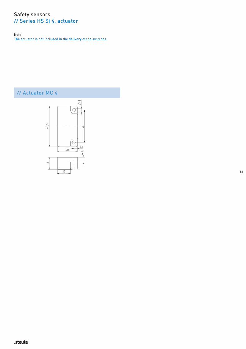
Safety sensors// Series HS Si 4, actuator
13
NoteThe actuator is not included in the delivery of the switches.
// Actuator MC 4

// BZ 16 Technical data
Safety sensors // Series BZ 16
Features/Options- Thermoplastic enclosure- Differential inputs:
induction/Hall sensor operating principle- Internal monitoring,
high manipulation protection- Potential-free outputs- 1 NC/1 NO contact or 2 NC contacts- Variable actuation- Switching capacity sao 10 mm, sar 20 mm- With wiring compartment
Standards IEC/EN 60947-5-3; EN 954-1; EN 1088Enclosure glass-fibre reinforced thermoplastic,
self-extinguishingActuator BZ 16-B1Protection class IP 67 or IP 69K to IEC/EN 60529 Contact material –Switching system Hall effect technologyContact types 1 NC/1NO contact or 2 NC contactsTermination terminal space with self-opening terminal
for max. 2 x 1.5 mm2
(including conductor ferrules)
Cable entry 3 x M20 x 1.5Cable length –Uimp 24 VDC +/ -15 %Max. fuse rating 0.25 A gL/gG D-fusePower consumption < 4 WOutputsUtilisation category AC-15, DC-13Ie/Ue 2.5 A/250 VAC, 2.5 A/24 VDCSwitching voltage max. 250 VACSwitching current max. 4 ASwitching capacity max. 1000 VAMax. fuse rating 4 A gL/gG D-fuseSwitching frequency max. 1 HzBounce duration –Ambient temperature 0 °C … +55 ºCMechanical life > 1 Mio. operationsElectrical life –Switching time “Close” < 200 msSwitching time “Open” < 200 msSwitching capacitysao 10 mmsar 20 mmHysteresis sao 1 mmAxial misalignment max. 3 mmApprovals H
14
Contact variants: Switch travel/contacts
multidirectional actuation
1 NC/1 NO contact BZ 16 11
2 NC contacts BZ 16 02
Ordering data BZ 16 11D-IP69K
Protection class IP 69KActuating directions (U, V)
1 NC/1 NO (2 NC)Series
Safety sensor
// Switching capacity // Actuator positioning
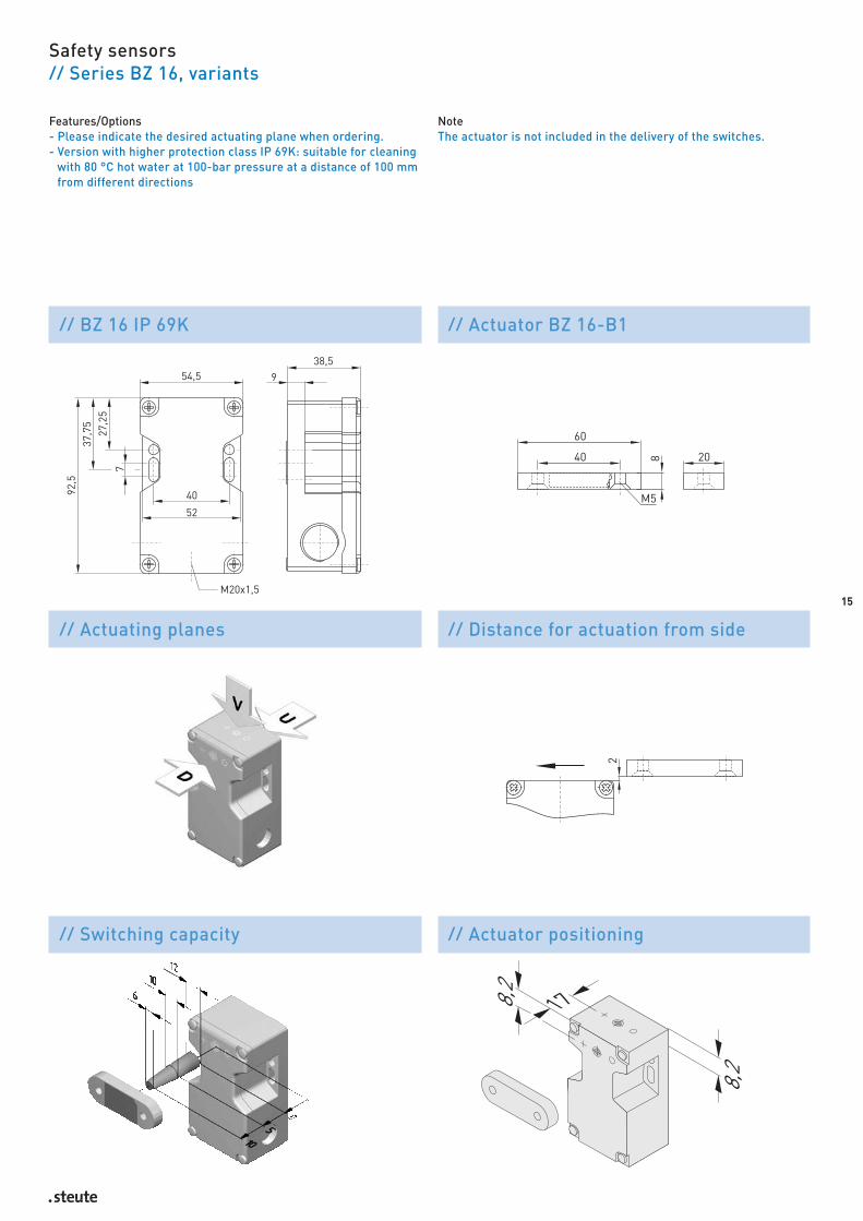
Safety sensors// Series BZ 16, variants
15
Features/Options- Please indicate the desired actuating plane when ordering.- Version with higher protection class IP 69K: suitable for cleaning
with 80 °C hot water at 100-bar pressure at a distance of 100 mmfrom different directions
// BZ 16 IP 69K // Actuator BZ 16-B1
// Actuating planes // Distance for actuation from side
NoteThe actuator is not included in the delivery of the switches.

17
Magnetic safety sensors
Cylindrical form// Series RC Si M30from page 20
Rectangular form// Series RC Si 56from page 22
Safety relay module// Series SRM 21 RT2from page 24
RC Si 56

18

1919
Magnetic safety sensors
ApplicationThe magnetic safety sensors of the RC Si series are suitable for
monitoring the position of sliding, hinged and removable protectivedoors. They can only be used for safety duties to DIN VDE 0660-209in combination with a safety guard monitor for protection up to Con-trol Category 4 to EN 954-1.
The use of magnetic safety sensors is of particular advantage incases where extremely dirty conditions can occur or high hygienicstandards need to be maintained. This is provided by the simplicity ofcleaning the units. A further advantage is the facility for concealedmounting behind non-magnetic materials.
Working surfaces and storage areas can be arranged without theneed for dust-collecting edges or other functionally required cutoutsor projections. The magnetic safety sensors of the RC Si series canalso be applied in cases where a precise approach is not possible andgreater tolerances are required.
Design and operating principleThese devices comprise a multi-channel magnetic safety sensor
and an actuating magnet. The magnetic safety sensors are actuatedby a coded magnet without any mechanical contact. The devices canbe selected with one NC and one NO contact or with two NC contacts.All described magnetic safety sensors are supplied with a pre-wiredcable.
The magnetic safety sensors of the RC Si series are protected toprotection class IP 67.
The mounting site of magnetic safety sensors must be free ofmagnetic fields.
All magnetic safety sensors described in this chapter bear the CEmark according to the Machinery Directive 98/37/EC.
ApplicationOn hinged doors On sliding doors

// RC SI M30 Technical data
Magnetic safety sensors, cylindrical form// Series RC Si M30
Features/Options- Metal enclosure- Long life- Reed contacts, coded- Actuation from front- Switching distance up to 8 mm- With pre-wired cable, cable length 1 metre- Available as Ex-version
Standards IEC/EN 60947-5-3; EN 954-1; EN 1088Enclosure aluminium brass, nickeled or stainless steel
1.4571Actuator MC 30, MC 30-NIROProtection class IP 67 or IP 69 K to IEC/EN 60529Contact material –Switching system Reed contactsContact types 1NC/1 NO contact or 2 NC contactsTermination Pre-wired cable H05 VV-F 5GCable section 4 x 0.5 mmCable length 1 mUimp –Power consumption –OutputsUtilisation category –Ie/Ue –Switching voltage max. 30 VDCSwitching current max. 125 mA, with LED: 20 mASwitching capacity max. 6 W/VAVoltage drop at Imax 2.5 V, with LED: 3 VShort-circuit current max. 750 mA for 50 ms, with LED: 30 mAMax. fuse rating –Switching frequency max. 5 HzAmbient temperature -20 °C … +70 ºCMechanical life > 10 Mio. operationsElectrical life –Switching capacitysao 8 mmsar 24 mmApprovals H
20
Contact variants: Switch travel/contacts
Bi-directional actuation
1 NC/1 NO contact RC Si M30 1Ö/1S
2 NC contacts RC Si M30 2Ö
Ordering data RC Si M30 1Ö/1S-IP69K-NIRO
Stainless steelenclosure
Protection class IP69K1 NC/1 NO contact (2Ö)
Series, Enclosure diameter M30Safety
Magnetic sensor

Magnetic safety sensors, cylindrical form// Series RC Si M30, actuator
21
Features/Options- Version with higher protection class IP 69K:
suitable for cleaning with 80 °C hot water at 100 bar pressure ata distance of 100 mm from different directions
- RCSi M30-NIRO: stainless steel enclosure 1.4571, actuator available with stainless steel enclosure 1.4571: MC30-NIRO
- RCSi M30-B: variant with mounting thread M16 x 1.5
NoteThe actuator is not included in the delivery of the switches.
// Mounting thread B
// Switching capacity
// Actuating magnet MC 30
// RC SI 56 Technical data
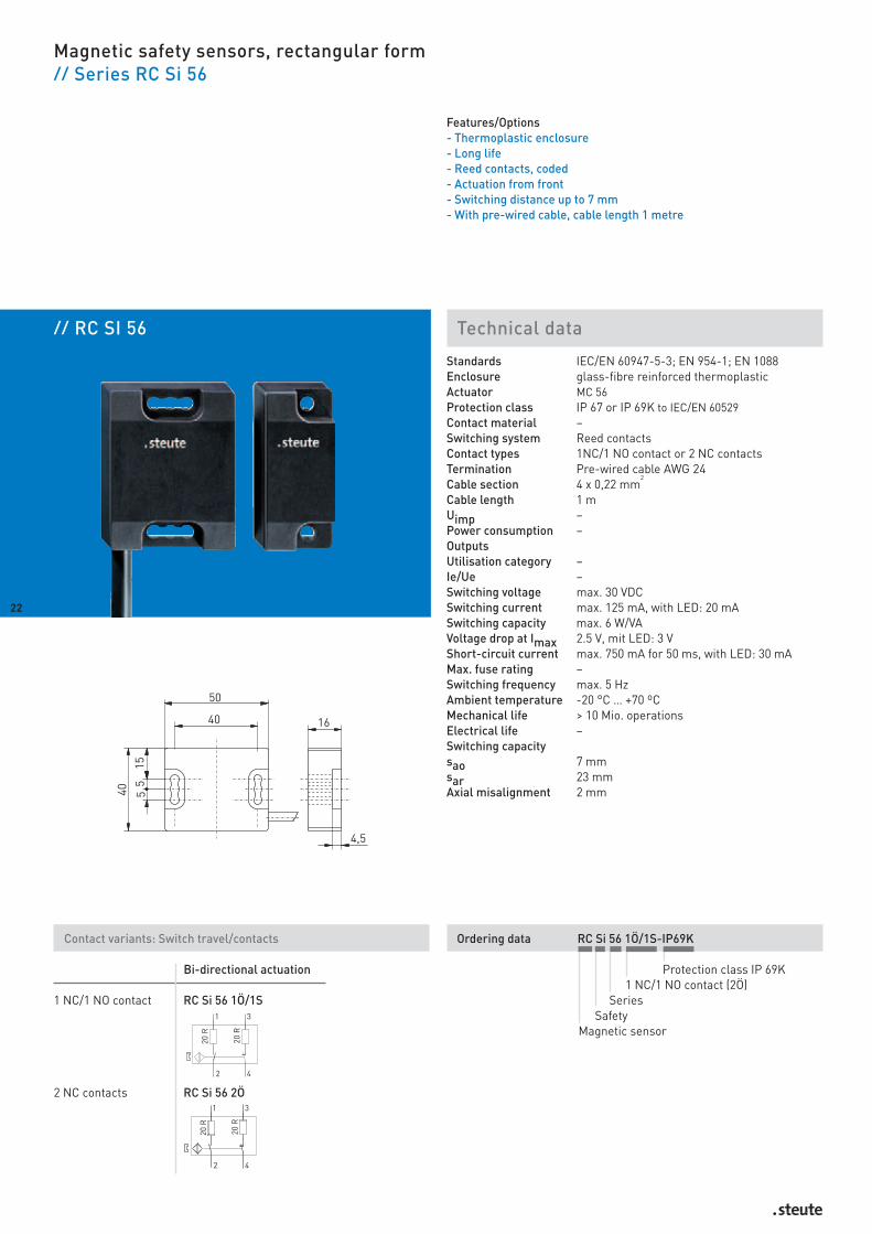
Magnetic safety sensors, rectangular form// Series RC Si 56
Features/Options- Thermoplastic enclosure- Long life- Reed contacts, coded- Actuation from front- Switching distance up to 7 mm- With pre-wired cable, cable length 1 metre
Standards IEC/EN 60947-5-3; EN 954-1; EN 1088Enclosure glass-fibre reinforced thermoplasticActuator MC 56Protection class IP 67 or IP 69K to IEC/EN 60529Contact material –Switching system Reed contactsContact types 1NC/1 NO contact or 2 NC contactsTermination Pre-wired cable AWG 24Cable section 4 x 0,22 mm
2
Cable length 1 mUimp –Power consumption –OutputsUtilisation category –Ie/Ue –Switching voltage max. 30 VDCSwitching current max. 125 mA, with LED: 20 mASwitching capacity max. 6 W/VAVoltage drop at Imax 2.5 V, mit LED: 3 VShort-circuit current max. 750 mA for 50 ms, with LED: 30 mAMax. fuse rating –Switching frequency max. 5 HzAmbient temperature -20 °C … +70 ºCMechanical life > 10 Mio. operationsElectrical life –Switching capacitysao 7 mmsar 23 mmAxial misalignment 2 mm
22
Contact variants: Switch travel/contacts
Bi-directional actuation
1 NC/1 NO contact RC Si 56 1Ö/1S
2 NC contacts RC Si 56 2Ö
Ordering data RC Si 56 1Ö/1S-IP69K
Protection class IP 69K1 NC/1 NO contact (2Ö)
SeriesSafety
Magnetic sensor

Magnetic safety sensors, rectangular form// Series RC Si 56, actuator
Features/Options- Version with higher protection class IP 69K:
suitable for cleaning with 80 °C hot water at 100 bar pressure ata distance of 100 mm from different directions
- MC56: compact design,suitable for 30, 40 and 50 mm profiles
- MC56-M: suitable for 30, 40 and 50 mm profiles
NoteThe actuator is not included in the delivery of the switches.
23
// Actuating magnet MC 56 // Actuating magnet MC 56-M
// Switching capacity

24
// SRM 21 RT2 Technical data
Safety relay module// Series SRM 21 RT2
Features/Options- Enclosure width: 22.5 mm - 2 NC contacts or NC/NO combination can be connected- Feedback circuit- 2 enabling paths- 1 transistor output- Manual or automatic reset- Switching position indication by LED
Standards IEC/EN 60204 -1, EN 60947-5-1, EN 954-1, BG-GS-ET 20
Enclosure black polycarbonate; polyamide terminalclamps, top hat section rail mounting to EN 50022
Termination screw terminals with + and - screwsCable section 1x 2.5 mm2/2x 1.5 mm2 strand including con-
ductor ferrules, 1x 4 mm2/2x 2.5 mm2 massiv Protection class Enclosure IP 40. Terminal block IP 20 to IEC
60529, shock protection to VBG 4Ue 24 VDC ±15%Power consumption ca. 2.5 WInputs 1 NC/1 NO contact or 2 NC contacts
1 feedback input, 1 reset inputOutputs 2 enabling paths: positive-guided contacts, 1
transistor output as signalling contactUtilisation category AC-15; DC-13Ie/Ueenabling paths 3 A/230 V; 2 A/24 VMax. output current transistor output Ia 20 mAMax. fuse ratingUe 2 A gL/gG D-fuseEnabling paths 6 A gL/gG D-fuseClassification stop category 0. Control category 4Dropout delay < 20 msMechanical life > 50 million operationsLED indications 4: operation, authorisation, inputs A and BDegree of pollution 3 to DIN VDE 0110Overvoltage category IIIAmbient temperature 0 °C … +55 °CApprovals H
24
Ordering data SRM 21 RT2
2 inputsautomatic reset
manual reset1 transistor output
2 enabling pathsSafety relay module
25
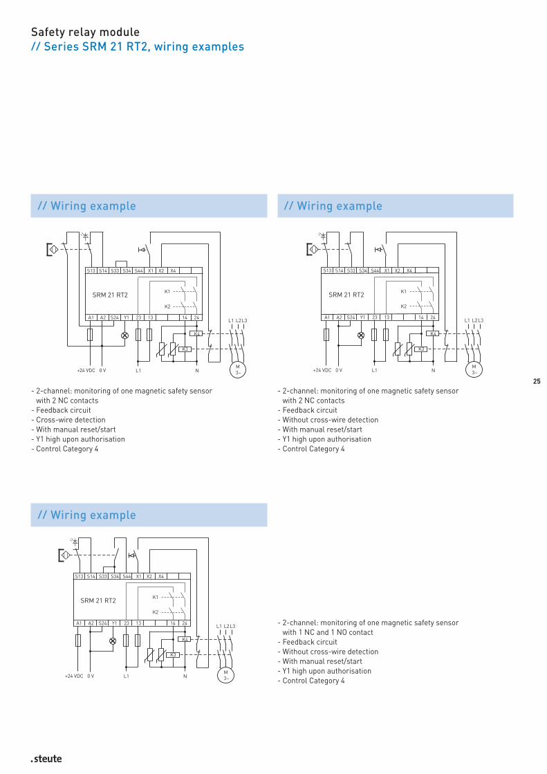
Safety relay module// Series SRM 21 RT2, wiring examples
// Wiring example
- 2-channel: monitoring of one magnetic safety sensor with 2 NC contacts
- Feedback circuit- Cross-wire detection- With manual reset/start- Y1 high upon authorisation- Control Category 4
// Wiring example
- 2-channel: monitoring of one magnetic safety sensor with 2 NC contacts
- Feedback circuit- Without cross-wire detection- With manual reset/start- Y1 high upon authorisation- Control Category 4
// Wiring example
- 2-channel: monitoring of one magnetic safety sensor with 1 NC and 1 NO contact
- Feedback circuit- Without cross-wire detection- With manual reset/start- Y1 high upon authorisation- Control Category 4


27
Magnetic sensors
Cylindrical form// Series RC 3from page 30 // Series RC 8from page 34// Series RC 10from page 36 // Series RC 13,5from page 38 // Series RC 15from page 40 // Series RC M20from page 42// Series RC 20from page 44 // Series RC 23from page 46// Series RC 30from page 48 // Series RC 60from page 50
RC M20
28
2929
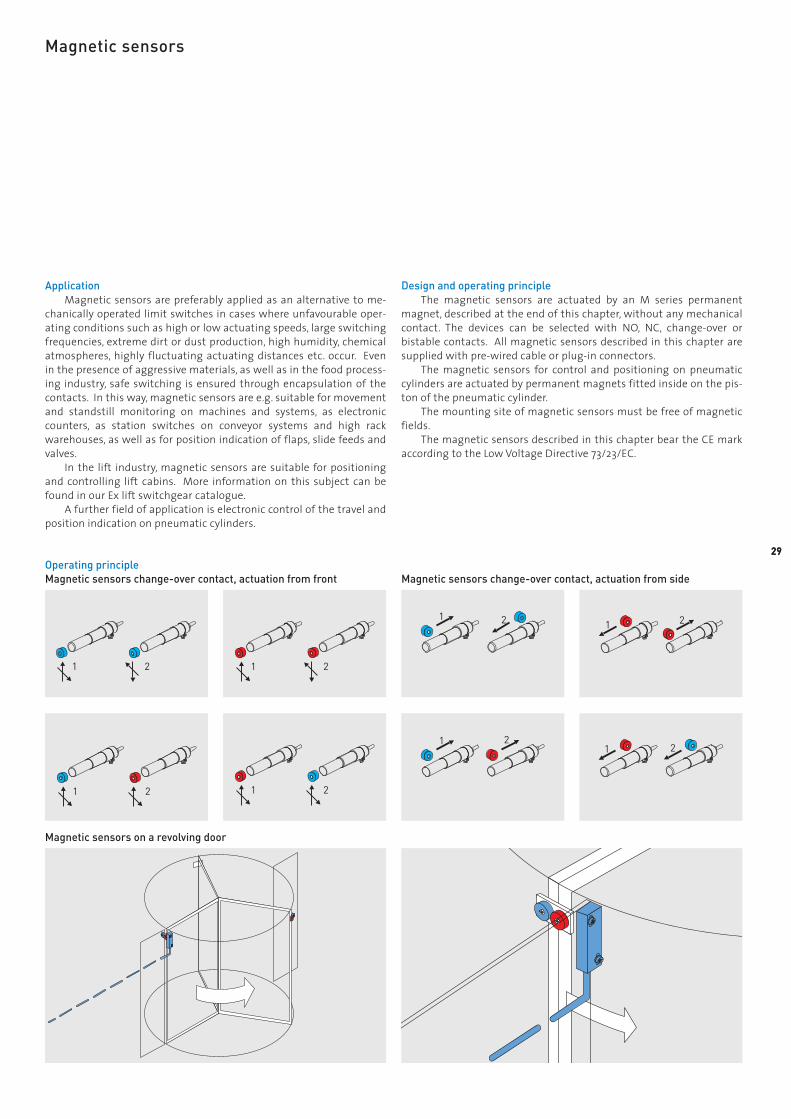
Magnetic sensors
ApplicationMagnetic sensors are preferably applied as an alternative to me-
chanically operated limit switches in cases where unfavourable oper-ating conditions such as high or low actuating speeds, large switchingfrequencies, extreme dirt or dust production, high humidity, chemicalatmospheres, highly fluctuating actuating distances etc. occur. Evenin the presence of aggressive materials, as well as in the food process-ing industry, safe switching is ensured through encapsulation of thecontacts. In this way, magnetic sensors are e.g. suitable for movementand standstill monitoring on machines and systems, as electroniccounters, as station switches on conveyor systems and high rackwarehouses, as well as for position indication of flaps, slide feeds andvalves.
In the lift industry, magnetic sensors are suitable for positioningand controlling lift cabins. More information on this subject can befound in our Ex lift switchgear catalogue.
A further field of application is electronic control of the travel andposition indication on pneumatic cylinders.
Design and operating principleThe magnetic sensors are actuated by an M series permanent
magnet, described at the end of this chapter, without any mechanicalcontact. The devices can be selected with NO, NC, change-over orbistable contacts. All magnetic sensors described in this chapter aresupplied with pre-wired cable or plug-in connectors.
The magnetic sensors for control and positioning on pneumaticcylinders are actuated by permanent magnets fitted inside on the pis-ton of the pneumatic cylinder.
The mounting site of magnetic sensors must be free of magneticfields.
The magnetic sensors described in this chapter bear the CE markaccording to the Low Voltage Directive 73/23/EC.
Operating principleMagnetic sensors change-over contact, actuation from front
Magnetic sensors on a revolving door
Magnetic sensors change-over contact, actuation from side

// RC 3 Technical data
Magnetic sensors, cylindrical form// Series RC 3
Features/Options- Metal enclosure- Long life- 1 Reed contact- Actuation from side and from front- Switching distance up to 29 mm, depending on the actuating magnet- With pre-wired cable, cable length 1 metre
Standards IEC/EN 60947-5-1Enclosure aluminium brass, nickeledActuator series M magnetProtection class IP 67; with plug-in connectors IP 42/65
to EN 60529Contact material rhodium; -W: tungstenSwitching system Reed contactsContact types NO or change-over contactTermination lead-free pre-wired cable, PVC H05VV-F or 3-
pole connector to DIN 41 524 Cable section 2 x 0.5 mm
2
Cable length 1.2 or 5 mSwitching voltage max. 250 VAC/DCSwitching current 1S: 2 A; 1W: 0.5 A; -W: 1 ASwitching capacity 1S: max. 50 VA/ W; 1W: max. 15 VA/ W;
-W: max. 25 VA/ WSwitching frequency max. 200 HzAmbient temperature -10 °C … +80 ºCMechanical life 10
9operations
Electrical life 109
operationsRepeat accuracy ± 0,02 mmResistance to vibrations 1S: 20 g, 1W: 10 g
30
Contact variants: Switch travel/contacts
bi-directional actuation
1 NO contact RC 3 1S
1 change-over contact RC 3 1W
Ordering data RC 3 1W-W-ST
ST plug-in connectorTungsten Reed contacts
1 change-over contact (1S 1 NO contact)Series
Magnetic sensor

Magnetic sensors, cylindrical form// Series RC 3, variants
31
Features/Options- Coupler for magnetic sensors with plug-in connectors M16 x 1:
for 24 VDC Hirschmann type Masei 3100 , protection class IP 42for 230 VAC Binder series 723, protection class IP 65
- Version for high temperatures up to +130 °C with silicon cableavailable
// Connector M 16x1, 3-pole // Connector M 16x1, 3-pole
Actuating direction from front from front
Switch travel
Contacts 1 NO contact 1 change-over contact
Actuating direction N or S N or S
Actuating magnet Switching distance [mm] Switching distance [mm]on off on off
M 50 U – – – –M 100 – – – –M 100 U – – – –M 200 3 16 3 5M 200 U 4 17 4 6M 300 22 39 22 25M 300 U 8 11 7 9M 300 U B 22 39 8 10M 400 U – – 24 26M 400 U B 29 43 22 24M 500 3 17 3 5M 600 20 38 21 23M 700 21 29 22 25
Actuating distances
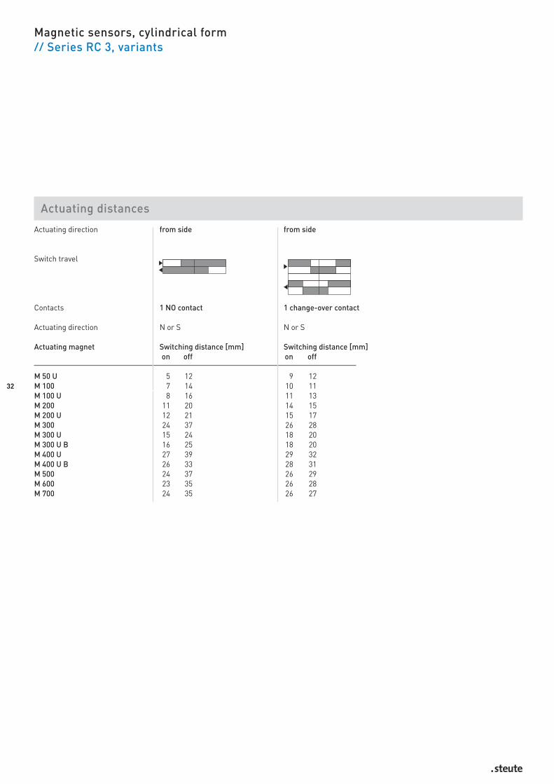
Magnetic sensors, cylindrical form// Series RC 3, variants
32
Actuating distances
Actuating direction from side from side
Switch travel
Contacts 1 NO contact 1 change-over contact
Actuating direction N or S N or S
Actuating magnet Switching distance [mm] Switching distance [mm]on off on off
M 50 U 5 12 9 12M 100 7 14 10 11M 100 U 8 16 11 13M 200 11 20 14 15M 200 U 12 21 15 17M 300 24 37 26 28M 300 U 15 24 18 20M 300 U B 16 25 18 20M 400 U 27 39 29 32M 400 U B 26 33 28 31M 500 24 37 26 29M 600 23 35 26 28M 700 24 35 26 27
33
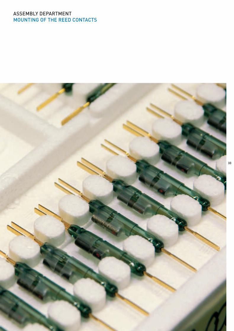
ASSEMBLY DEPARTMENTMOUNTING OF THE REED CONTACTS

// RC 8 Technical data
Magnetic sensors, cylindrical form// Series RC 8
Features/Options- Metal enclosure- Long life- 1 Reed contact- Actuation from front and from side- Switching distance up to 39 mm depending on the actuating magnet- With pre-wired cable, cable length 1 metre
Standards IEC/EN 60947-5-1Enclosure brass, nickeledActuator series M permanent magnetProtection class IP 67 to EN 60529Contact material rhodiumSwitching system reed contactsContact types NO contactTermination pre-wired cable, LiYY 2 x AWG26Cable section 2 x 0.14 mm
2
Cable length 1 mSwitching voltage max. 200 VAC/DCSwitching current 1 ASwitching capacity max. 20 W/VASwitching frequency max. 200 HzBounce duration –Ambient temperature –10 °C … +80 ºCMechanical life 10
9Operations
Electrical life 109
OperationsRepeat accuracy ± 0.02 mmResistance to vibrations 20 g
34
Contact variants: Switch travel/contacts
bi-directional actuation
1 NO contact RC 8 1S
Ordering data RC 8 1S
1 NO contactSeries
Magnetic sensor

Actuating distances
35
Magnetic sensors, cylindrical form// Series RC 8
Features/Options- Version for high temperatures up to +130 °C with silicon cable
available
Actuating direction from front from side
Switch travel
Contacts 1 NO contact 1 NO contact
Actuating direction N or S N or S
Actuating magnet Switching distance [mm] Switching distance [mm]on off on off
M 50 U 10 15 13 17M 100 12 18 14 17M 100 U 15 20 16 20M 200 17 24 19 23M 200 U 19 25 20 25M 300 36 47 32 40M 300 U 23 29 23 28M 300 U B 23 30 23 28M 400 U 39 49 35 42M 400 U B 39 48 34 41M 500 17 23 32 40M 600 36 46 31 38M 700 39 48 31 38

// RC 10 Technical data
Magnetic sensors, cylindrical form// Series RC 10
Features/Options- Thermoplastic enclosure- Long life- 1 Reed contact- Actuation from front and from side- Switching distance up to 40 mm depending on the actuating magnet- With pre-wired cable, cable length 1 metre
Standards IEC/EN 60947-5-1Enclosure POMActuator Series M permanent magnetProtection class IP 67 to EN 60529Contact material rhodiumSwitching system reed contactsContact types NO contactTermination pre-wired cable, PVC LiYYCable section 2 x 0.34 mm
2
Cable length 1 mSwitching voltage max. 250 VAC/DCSwitching current 1 ASwitching capacity max. 100 W/VASwitching frequency max. 200 HzBounce duration –Ambient temperature -10 °C … +80 ºCMechanical life 10
9operations
Electrical life 109
operationsRepeat accuracy ± 0,02 mmResistance to vibrations 20 g
36
Contact variants: Switch travel/contacts
bi-directional actuation
1 NO contact RC 10 1S
Ordering data RC 10 1S
1 NO contactSeries
Magnetic sensor
37
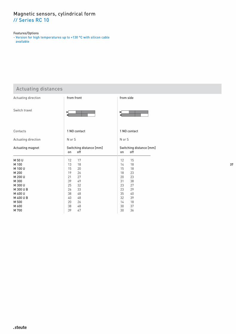
Magnetic sensors, cylindrical form// Series RC 10
Features/Options- Version for high temperatures up to +130 °C with silicon cable
available
Actuating direction from front from side
Switch travel
Contacts 1 NO contact 1 NO contact
Actuating direction N or S N or S
Actuating magnet Switching distance [mm] Switching distance [mm]on off on off
M 50 U 12 17 12 15M 100 13 18 14 18M 100 U 15 20 15 18M 200 19 26 18 23M 200 U 21 27 20 23M 300 39 49 31 38M 300 U 25 32 23 27M 300 U B 26 33 23 29M 400 U 38 48 35 40M 400 U B 40 48 32 39M 500 20 26 14 18M 600 38 48 30 37M 700 39 47 30 36
Actuating distances

38
// RC 13,5 Technical data
Magnetic sensors, cylindrical form// Series RC 13,5
Features/Options- Metal enclosure- Long life- 1 Reed contact- Actuation from front- Switching distance up to 30 mm depending on the actuating magnet- With pre-wired cable, cable length 1 metre
Standards IEC/EN 60947-5-1Enclosure brass, nickeledActuator series M permanent magnetProtection class IP 67 to EN 60529Contact material silverSwitching system reed contactsContact types NC contact, NO contact or change-over
contactTermination pre-wired cable, H05VV-FCable section 1S: 3 x 0.75 mm
2, 1W: 4 x 0.75 mm
2
Cable length 1, 2 or 5 mSwitching voltage 250 VSwitching current 1.5 ASwitching capacity 1Ö, 1W: max. 50 VA/W, 1S: max. 100 VA/WSwitching frequency max. 200 HzAmbient temperature -10 °C … +80 ºCMechanical life 10
9operations
Electrical life 109
operationsRepeat accuracy ± 0.02 mmResistance to vibrations 1S: 50 … 100 g, 1Ö, 1W: 10 … 50 g
Contact variants: Switch travel/contacts
actuation from front
1 NC contact RC 13,5 1Ö
1 NO contact RC 13,5 1S
1 change-over contact RC 13,5 1W
Ordering data RC 13,5 1W
1 change-over contact (1Ö 1 NCcontact, 1S 1 NO contact)
SeriesMagnetic sensor

39
Actuating direction from front from front from front
Switch travel
Contacts 1 NC contact 1 NO contact 1 change-over contact
Actuating direction NC or S N or S N or S
Actuating magnet Switching distance [mm] Switching distance [mm] Switching distance [mm]on off on off on off
M 50 U 4 7 – – 4 7M 100 10 13 3 11 10 13M 100 U 10 13 3 11 10 13M 200 13 16 7 17 13 16M 200 U 13 16 7 17 13 16M 300 17 20 10 24 17 20M 300 U 17 20 10 24 17 20M 400 U 33 37 28 43 33 37M 700 30 35 25 40 30 35
Magnetic sensors, cylindrical form// Series RC 13,5
Features/Options- Version for high temperatures up to +130 °C with silicon cable
available
Actuating distances

Ordering data RC 15 1W
1 change-over contact (1Ö 1 NCcontact, 1S 1 NO contact)
SeriesMagnetic sensor
// RC 15 Technical data
Magnetic sensors, cylindrical form// Series RC 15
Features/Options- Metal enclosure- Long life- 1 Reed contact- Actuation from front- Switching distance up to 25 mm depending on the actuating magnet- With pre-wired cable, cable length 1 metre
Standards IEC/EN 60947-5-1Enclosure brass, nickeledActuator series M permanent magnetProtection class IP 67 to EN 60529Contact material silverSwitching system reed contactsContact types NC contact, NO contact or change-over
contactTermination pre-wired cable, H05VV-FCable section 1S: 3 x 0.75 mm
2, 1W: 4 x 0.75 mm
2
Cable length 1, 2 or 5 mSwitching voltage max. 250 VAC/DCSwitching current 1.5 ASwitching capacity 1Ö, 1W: max. 50 VA/W, 1S: max. 100 VA/WSwitching frequency max. 200 HzAmbient temperature -10 °C … +80 ºCMechanical life 10
9operations
Electrical life 109
operationsRepeat accuracy ± 0.02 mmResistance to vibrations 1S: 50 … 100 g, 1Ö, 1W: 10 … 50 g
Contact variants: Switch travel/contacts
actuation from front
1 NC contact RC 15 1Ö
1 NO contact RC 15 1S
1 change-over contact RC 15 1W
40
41
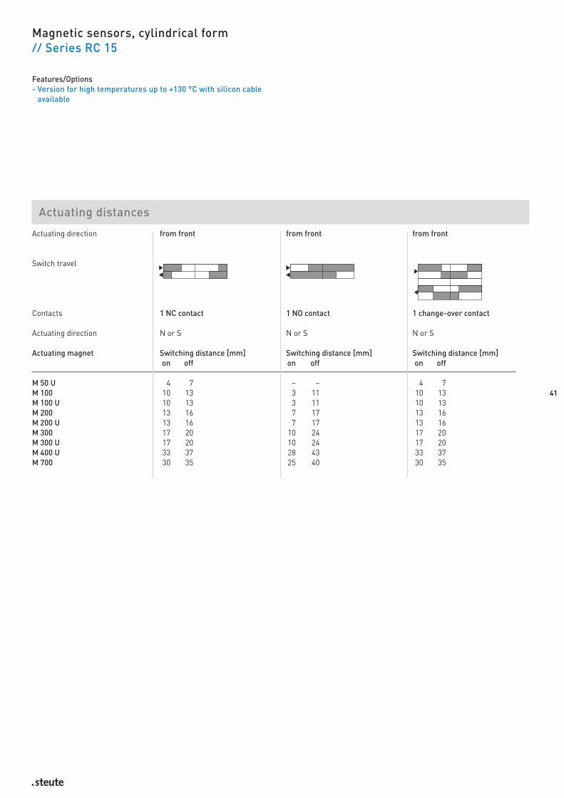
Actuating direction from front from front from front
Switch travel
Contacts 1 NC contact 1 NO contact 1 change-over contact
Actuating direction N or S N or S N or S
Actuating magnet Switching distance [mm] Switching distance [mm] Switching distance [mm]on off on off on off
M 50 U 4 7 – – 4 7M 100 10 13 3 11 10 13M 100 U 10 13 3 11 10 13M 200 13 16 7 17 13 16M 200 U 13 16 7 17 13 16M 300 17 20 10 24 17 20M 300 U 17 20 10 24 17 20M 400 U 33 37 28 43 33 37M 700 30 35 25 40 30 35
Magnetic sensors, cylindrical form// Series RC 15
Features/Options- Version for high temperatures up to +130 °C with silicon cable
available
Actuating distances

// RC M20 Technical data
Magnetic sensors, cylindrical form// Series RC M20
Features/Options- Metal enclosure- Long life- 1 Reed contact- Actuation from front, actuation from side only for change-over
contacts- Switching distance up to 30 mm depending on the actuating magnet- With pre-wired cable, cable length 1 metre- Available in high-grade steel
Standards IEC/EN 60947-5-1Enclosure brass, nickeledActuator series M permanent magnetProtection class IP 67 to EN 60529Contact material silverSwitching system reed contactsContact types NO contact or change-over contact, grid or
change-over contact latchingTermination Pre-wired cable, H05VV-FCable section 1S: 3 x 0.75 mm
2, 1W: 4 x 0.75 mm
2
Cable length 1, 2 oder 5 mSwitching voltage max. 250 VAC/DCSwitching current 1.5 ASwitching capacity 1Ö, 1W: max. 50 VA/W, 1S: max. 100 VA/WSwitching frequency max. 200 HzAmbient temperature -10 °C … +80 ºCMechanical life 10
9operations
Electrical life 109
operationsRepeat accuracy ± 0.02 mmResistance to vibrations 1S: 50 … 100 g, 1Ö, 1W: 10 … 50 g
42
Contact variants: Switch travel/contacts
actuation from front actuation from side
1 NO contact RC M20 1S
1 grid RC M20 1Sr RC M20 1Sr
1 change-over contact RC M20 1W
1 change-over contactlatching RC M20 1Wr RC M20 1Wr
Ordering data RC M20 1W
1 change-over contact (1Ö 1 NCcontact, 1S 1 NO contact)
SeriesMagnetic sensor

43
Magnetic sensors, cylindrical form// Series RC M20
Actuating direction from front from front from front
Switch travel
Contacts 1 change-over contact 1 bistable contact 1 bistable change-over contactActuating direction N or S N/S N/S
Actuating magnet Switching distance [mm] Switching distance [mm] Switching distance [mm]on off on off on off
M 50 U 4 7 12 6 – –M 100 10 13 22 12 20 40M 100 U 10 13 22 12 20 40M 200 13 16 30 30 25 50M 200 U 13 16 30 30 25 50M 300 17 20 37 23 30 60M 300 U 17 20 37 23 30 60M 400 U 33 37 63 43 50 90M 700 30 35 60 40 50 75
Actuating direction from side from side
Switch travel
Contacts 1 bistable contact 1 bistable change-over contactActuating direction N or S N or S
Actuating magnet Switching distance [mm] Switching distance [mm]on off on off
M 50 U – –M 100 15 20M 100 U 15 20M 200 20 25M 200 U 20 25M 300 25 30M 300 U 25 30M 400 U 30 35M 700 40 50
Actuating distances
Features/Options- Version for high temperatures up to +130 °C with silicon cable
available

// RC 20 Technical data
Magnetic sensors, cylindrical form// Series RC 20
Features/Options- Metal enclosure- Long life- 1 Reed contact- Actuation from front and from side- Switching distance up to 41 mm depending on the actuating magnet- With pre-wired cable, cable length 1 metre
Standards IEC/EN 60947-5-1Enclosure brass, nickeledActuator series M permanent magnetProtection class IP 67; with plug-in connector IP 42/65
to EN 60529Contact material rhodiumSwitching system reed contactsContact types NO contact or change-over contactTermination lead-free pre-wired cable, PVC H05VV-F
or 3-pole connector to DIN 41 524 Cable section 2 x 0.5 mm
2 ,3 x 0.5 mm
2
Cable length 1, 2 or 5 mSwitching voltage 1S: max. 250 VAC/DC, 1W: max. 175 VAC/DCSwitching current 1S: max. 0,5 A, 1W: max. 0.25 ASwitching capacity 1S: max. 50 VA/W, 1W: max. 3 VA/WSwitching frequency max. 200 HzAmbient temperature -10 °C … +80 ºCMechanical life 10
9operations
Electrical life 109
operationsRepeat accuracy ± 0.02 mmResistance to vibrations 1S: 20 g, 1W: 30 g
Contact variants: Switch travel/contacts
bi-directional actuation
1 NO contact RC 20 1S
1 change-over contact RC 20 1W
Ordering data RC 20 1W-ST
with plug-in connector1 change-over contact (1S 1 NO contact
SeriesMagnetic sensor
44

Magnetic sensors, cylindrical form// Series RC 20, variants
Features/Options- Coupling for magnetic sensors with plug-in connector M16 x 1:
for 24 VDC Hirschmann Type Masei 3100 , protection class IP 42for 230 VAC Binder Series 723, protection class IP 65
- Version for high temperatures up to +130 °C with silicon cableavailable
// Connector M 16x1, 3-pole // Angled connector M 16x1, 3-pole
45
Actuating direction from front from side
Switch travel
Contacts 1 NO contact 1 NO contact
Actuating direction N or S N or S
Actuating magnet Switching distance [mm] Switching distance [mm]on off on off
M 50 U 12 16 11 14M 100 14 18 12 15M 100 U 16 19 14 16M 200 19 24 16 20M 200 U 20 25 17 21M 300 25 29 21 24M 300 U 25 29 21 24M 300 U B 25 30 21 24M 400 U 41 47 32 37M 400 U B 41 47 32 37M 500 20 25 30 35M 600 39 47 29 34M 700 40 47 29 33
Actuating distances
// RC 23 Technical data
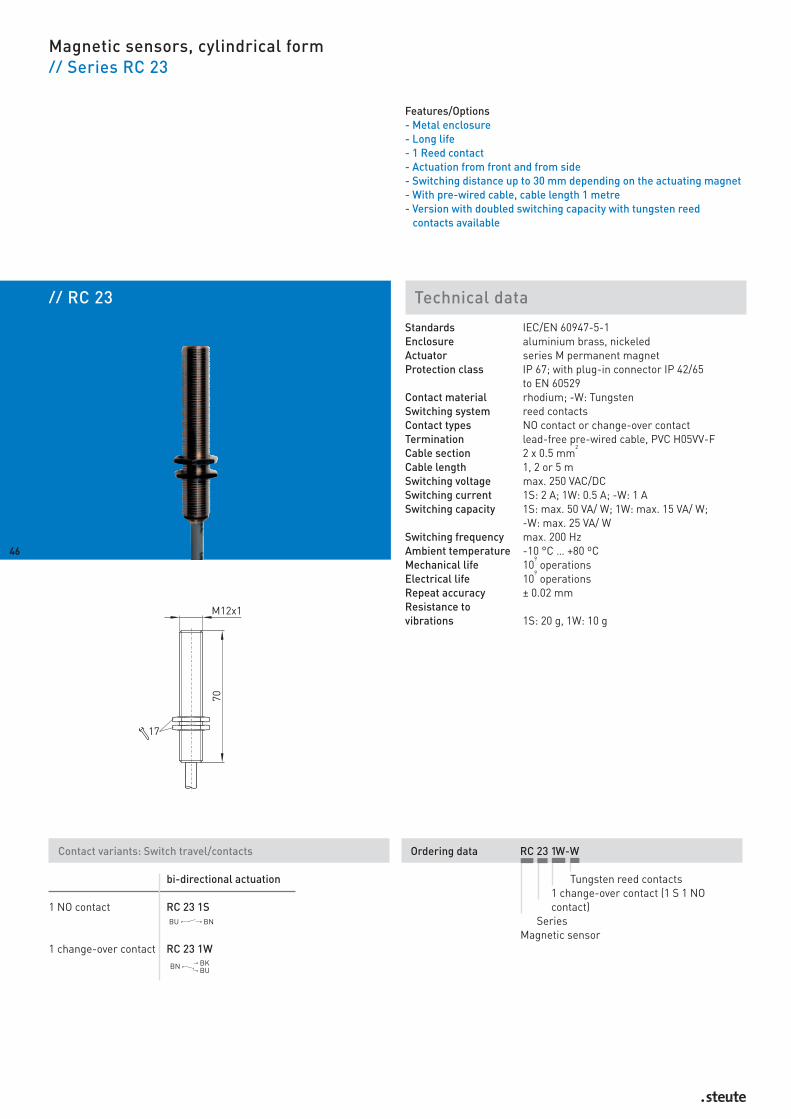
Magnetic sensors, cylindrical form// Series RC 23
Features/Options- Metal enclosure- Long life- 1 Reed contact- Actuation from front and from side- Switching distance up to 30 mm depending on the actuating magnet- With pre-wired cable, cable length 1 metre- Version with doubled switching capacity with tungsten reed
contacts available
Standards IEC/EN 60947-5-1Enclosure aluminium brass, nickeledActuator series M permanent magnetProtection class IP 67; with plug-in connector IP 42/65
to EN 60529Contact material rhodium; -W: TungstenSwitching system reed contactsContact types NO contact or change-over contactTermination lead-free pre-wired cable, PVC H05VV-FCable section 2 x 0.5 mm
2
Cable length 1, 2 or 5 mSwitching voltage max. 250 VAC/DCSwitching current 1S: 2 A; 1W: 0.5 A; -W: 1 ASwitching capacity 1S: max. 50 VA/ W; 1W: max. 15 VA/ W;
-W: max. 25 VA/ WSwitching frequency max. 200 HzAmbient temperature -10 °C … +80 ºCMechanical life 10
9operations
Electrical life 109
operationsRepeat accuracy ± 0.02 mmResistance to vibrations 1S: 20 g, 1W: 10 g
Contact variants: Switch travel/contacts
bi-directional actuation
1 NO contact RC 23 1S
1 change-over contact RC 23 1W
Ordering data RC 23 1W-W
Tungsten reed contacts1 change-over contact (1 S 1 NOcontact)
SeriesMagnetic sensor
46

47
Magnetic sensors, cylindrical form// Series RC 23
Features/Options- Version for high temperatures up to +130 °C with silicon cable
available
Actuating direction from front from side
Switch travel
Contacts 1 NO contact 1 NO contact
Actuating direction N or S N or S
Actuating magnet Switching distance [mm] Switching distance [mm]on off on off
M 50 U 1 8 8 14M 100 2 10 9 16M 100 U 6 14 11 18M 200 8 18 14 21M 200 U 10 19 16 22M 300 29 42 29 39M 300 U 13 23 19 26M 300 U B 14 24 19 27M 400 U 30 43 31 42M 400 U B 29 41 30 43M 500 10 20 29 39M 600 28 41 28 29M 700 29 41 27 38
Actuating distances

Ordering data RC 30 1W-W
Tungsten reed contacts1 change-over contact (1S 1 NO contact)
SeriesMagnetic sensor
// RC 30 Technical data
Magnetic sensors, cylindrical form// Series RC 30
Features/Options- Thermoplastic enclosure- Long life- 1 Reed contact- Actuation from front and from side- Switching distance up to 36 mm depending on the actuating magnet- With pre-wired cable, cable length 1 metre- Version with doubled switching capacity with tungsten reed
contacts available
Standards IEC/EN 60947-5-1Enclosure glass-fibre reinforced polyamideActuator series M permanent magnetProtection class IP 67; with plug-in connector IP 42/65
to EN 60529Contact material rhodium; -W: TungstenSwitching system reed contactsContact types NO contact or change-over contactTermination lead-free pre-wired cable, PVC H05VV-F or
3-pole connector to DIN 41 524 Cable section 2 x 0.5 mm
2
Cable length 1, 2 oder 5 mSwitching voltage max. 250 VAC/DCSwitching current 1S; 1W: 0,5 A; -W: 1 ASwitching capacity 1S: max. 50 VA/ W; 1W: max. 15 VA/ W;
-W: max. 25 VA/ WSwitching frequency max. 200 HzAmbient temperature -10 °C … +80 ºCMechanical life 10
9operations
Electrical life 109
operationsRepeat accuracy ± 0.02 mmResistance to vibrations 1S: 20 g, 1W: 10 g
Contact variants: Switch travel/contacts
bi-directional actuation
1 NO contact RC 30 1S
1 change-over contact RC 30 1W
48

49
Magnetic sensors, cylindrical form// Series RC 30
Features/Options- Version for high temperatures up to +130 °C with silicon cable
available
Actuating direction from front from side
Switch travel
Contacts 1 NO contact 1 NO contact
Actuating direction N or S N or S
Actuating magnet Switching distance [mm] Switching distance [mm]on off on off
M 50 U 8 10 3 5M 100 10 15 5 7M 100 U 12 13 4 5M 200 16 18 7 9M 200 U 17 20 9 10M 300 33 37 19 22M 300 U 21 24 11 13M 300 U B 20 23 12 14M 400 U 36 39 21 24M 400 U B 34 38 21 23M 500 13 16 21 24M 600 33 36 18 20M 700 34 37 18 20
Actuating distances

// RC 60 Technical data
Magnetic sensors, cylindrical form// Series RC 60
Features/Options- Thermoplastic enclosure- Long life- 1 Reed contact- Actuation from front and from side- Switching distance up to 33 mm depending on the actuating magnet- With pre-wired cable, cable length 1 metre- Version with doubled switching capacity with tungsten reed
contacts available
Standards IEC/EN 60947-5-1Enclosure glass-fibre reinforced polyamideActuator series M permanent magnetProtection class IP 67 to EN 60529Contact material rhodium; -W: tungstenSwitching system reed contactsContact types NO contact, change-over contact or gridTermination lead-free pre-wired cable, PVC H05VV-F or
3-pole connector to DIN 41 524 Cable section 2 x 0.5 mm
2
Cable length 1, 2 oder 5 mSwitching voltage max. 250 VAC/DCSwitching current 1S: 2 A; 1W: 0,5 A; -W: 1 ASwitching capacity 1S: max. 50 VA/ W; 1W: max. 15 VA/ W;
-W: max. 25 VA/ WSwitching frequency max. 200 HzAmbient temperature -10 °C … +80 ºCMechanical life 10
9operations
Electrical life 109
operationsRepeat accuracy ± 0.02 mmResistance to vibrations 1S: 20 g, 1W: 10 g
Contact variants: Switch travel/contacts
bi-directional actuation
1 NO contact RC 60 1S
1 grid RC 60 1Sr
1 change-over contact RC 60 1W
Ordering data RC 60 1W-W-ST
ST plug-in connectorTungsten reed contacts
1 change-over contact (1S 1 NO contact, 1Sr 1 Raster)
SeriesMagnetic sensor
50

Magnetic sensors, cylindrical form// Series RC 60, variants
Features/Options- Coupler for magnetic sensors with plug-in connector M12 x 1: for
250 VAC Escha- Version for high temperatures up to +130 °C with silicon cable
available
// with connector // with connector
51
Actuating direction from front from side
Switch travel
Contacts 1 NO contact 1 NO contact
Actuating direction N or S N or S
Actuating magnet Switching distance [mm] Switching distance [mm]on off on off
M 50 U 3 11 9 14M 100 4 13 10 16M 100 U 6 15 13 18M 200 9 19 15 23M 200 U 10 20 17 23M 300 30 44 29 42M 300 U 15 25 20 28M 300 U B 15 25 20 28M 400 U 30 45 33 43M 400 U B 30 43 33 43M 500 10 20 11 18M 600 29 43 29 40M 700 30 44 29 40
Actuating distances

52
Magnetic sensors, cylindrical form// Series RC 60, variants
Actuating distances
Actuating direction from front from side
Switch travel
Contacts 1 change-over contact 1 change-over contact
Actuating direction N or S N or S
Actuating magnet Switching distance [mm] Switching distance [mm]on off on off
M 50 U – – 9 12M 100 – – 10 11M 100 U – – 11 13M 200 3 5 14 15M 200 U 4 6 15 17M 300 22 25 26 28M 300 U 7 9 18 20M 300 U B 8 10 18 20M 400 U 24 26 29 32M 400 U B 22 24 28 31M 500 3 5 26 29M 600 21 23 26 28M 700 22 25 26 27

53
PRODUCTION DEPARTMENT ASSEMBLYENCAPSULATION OF MAGNETIC SENSORS

55
Magnetic sensors
Rectangular form// Series RC 4from page 56 // Series RC 5from page 58 // Series RC 40from page 60// Series RC 42from page 62 // Series RC 50from page 64 // Series RC 80from page 66 // Series RC 90from page 68 // Series RC 96from page 70
RC 96

// RC 4 Technical data
Magnetic sensors, rectangular form// Series RC 4
Features/Options- Thermoplastic enclosure- Long life- 1 Reed contact- Actuation from front and from side- Switching distance up to 48 mm depending on the actuating magnet- With pre-wired cable, cable length 1 metre
Standards IEC/EN 60947-5-1Enclosure thermoplasticActuator series M permanent magnetProtection class IP 67 to EN 60529Contact material rhodiumSwitching system reed contactsContact types NO contactTermination Pre-wired cable, PVC LiYY 2 x AWG26Cable section 2 x 0.14 mm
2
Cable length 1, 2 or 5 mSwitching voltage max. 230 VDC / 125 VACSwitching current max. 0,5 ASwitching capacity max. 15 VA/WSwitching frequency max. 200 HzBounce duration –Ambient temperature –10 °C … +80 ºCMechanical life 10
9operations
Electrical life 109
operationsRepeat accuracy ± 0.02 mmResistance to vibrations 20 g
Contact variants: Switch travel/contacts
actuation from side
1 NO contact RC 4 1S
Ordering data RC 4 1S
1 NO contactSeries
Magnetic sensor
56

57
Magnetic sensors, rectangular form// Series RC 4
Features/Options- Version for high temperatures up to +130 °C with silicon cable
available
Actuating direction from front from side
Switch travel
Contacts 1 NO contact 1 NO contact
Actuating direction N or S N or S
Actuating magnet Switching distance [mm] Switching distance [mm]on off on off
M 50 U 16 21 17 22M 100 18 24 18 23M 100 U 21 27 20 25M 200 24 32 22 27M 200 U 26 33 24 30M 300 47 58 38 46M 300 U 30 38 27 33M 300 U B 31 38 28 33M 400 U 48 59 40 48M 400 U B 46 57 39 46M 500 18 23 38 47M 600 46 58 37 45M 700 47 58 36 45
Actuating distances
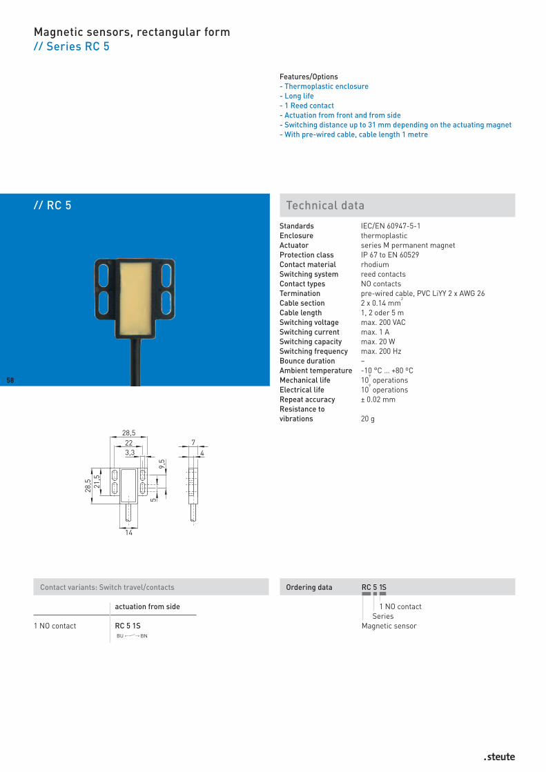
Ordering data RC 5 1S
1 NO contactSeries
Magnetic sensor
// RC 5 Technical data
Magnetic sensors, rectangular form// Series RC 5
Features/Options- Thermoplastic enclosure- Long life- 1 Reed contact- Actuation from front and from side- Switching distance up to 31 mm depending on the actuating magnet- With pre-wired cable, cable length 1 metre
Standards IEC/EN 60947-5-1Enclosure thermoplasticActuator series M permanent magnetProtection class IP 67 to EN 60529Contact material rhodiumSwitching system reed contactsContact types NO contactsTermination pre-wired cable, PVC LiYY 2 x AWG 26Cable section 2 x 0.14 mm
2
Cable length 1, 2 oder 5 mSwitching voltage max. 200 VACSwitching current max. 1 ASwitching capacity max. 20 WSwitching frequency max. 200 HzBounce duration –Ambient temperature -10 °C … +80 ºCMechanical life 10
9operations
Electrical life 109
operationsRepeat accuracy ± 0.02 mmResistance to vibrations 20 g
Contact variants: Switch travel/contacts
actuation from side
1 NO contact RC 5 1S
58

59
Magnetic sensors, rectangular form// Series RC 5
Features/Options- Version for high temperatures up to +130 °C with silicon cable
available
Actuating direction from front from side
Switch travel
Contacts 1 NO contact 1 NO contact
Actuating direction N or S N or S
Actuating magnet Switching distance [mm] Switching distance [mm]on off on off
M 50 U – – 12 18M 100 1 10 12 19M 100 U 3 13 15 21M 200 6 18 17 23M 200 U 9 19 19 24M 300 26 42 29 40M 300 U 11 23 21 28M 300 U B 10 13 21 28M 400 U 28 44 31 42M 400 U B 28 44 31 41M 500 6 19 29 41M 600 25 41 27 39M 700 26 42 27 39
Actuating distances

// RC 40 Technical data
Magnetic sensors, rectangular form// Series RC 40
Features/Options- Thermoplastic enclosure- Long life- 1 Reed contact- Actuation from front and from side- Switching distance up to 29 mm depending on the actuating magnet- With pre-wired cable, cable length 1 metre
Standards IEC/EN 60947-5-1Enclosure glass-fibre reinforced polyamideActuator series M permanent magnetProtection class IP 67 to EN 60529Contact material rhodiumSwitching system reed contactsContact types NO contact, change-over contact, change-over
or bi-stable latching contactTermination pre-wired cable, 1W: PVC LiYY, 1S: AWG 26Cable section 2 x 0.14 mm
2 / 3 x 0.14 mm
2
Cable length 1, 2 or 5 mSwitching voltage 1 S: max. 250 VDC / 1 W: max. 175 VDCSwitching current 1 S: max. 1 A / 1 W = max. 0,25 ASwitching capacity 1 S: max. 15 W / 1 W = max. 3 WSwitching frequency max. 200 HzAmbient temperature –10 °C … +80 ºCMechanical life 10
9operations
Electrical life 109
operationsRepeat accuracy ± 0.02 mmResistance to vibrations 20 g
Contact variants: Switch travel/contacts
actuation from side
1 NO contact RC 40 1S
1 bi-stable contact RC 40 1Sr
1 change-over contact RC 40 1W
1 change-over contact RC 40 1Wrlatching
Ordering data RC 40 1W
1 change-over contact (1S 1 NOcontact, 1Sr 1 change-over contact,1Wr 1 change-over contact latching)
SeriesMagnetic sensor
60

61
Magnetic sensors, rectangular form// Series RC 40
Features/Options- Version for high temperatures up to +130 °C with silicon cable
available
Actuating direction from front from side
Switch travel
Contacts 1 NO contact 1 NO contact
Actuating direction N or S N or S
Actuating magnet Switching distance [mm] Switching distance [mm]on off on off
M 50 U 15M 100 15M 100 U 15M 200 15M 200 U 15M 300 15M 300 U 15M 300 U B 22 39 15 24M 400 U – – 27 39M 400 U B 29 43 29 43M 500 3 17 24 37M 600 20 38 23 35M 700 21 29 24 35
Actuating distances

Ordering data RC 42 1W-W
Tungsten reed contacts1 change-over contact (1Ö 1 NC contact,1S 1 NO contact,1Sr 1 bi-stable contact,1Wr 1 change-over contact latching)
SeriesMagnetic sensor
// RC 42 Technical data
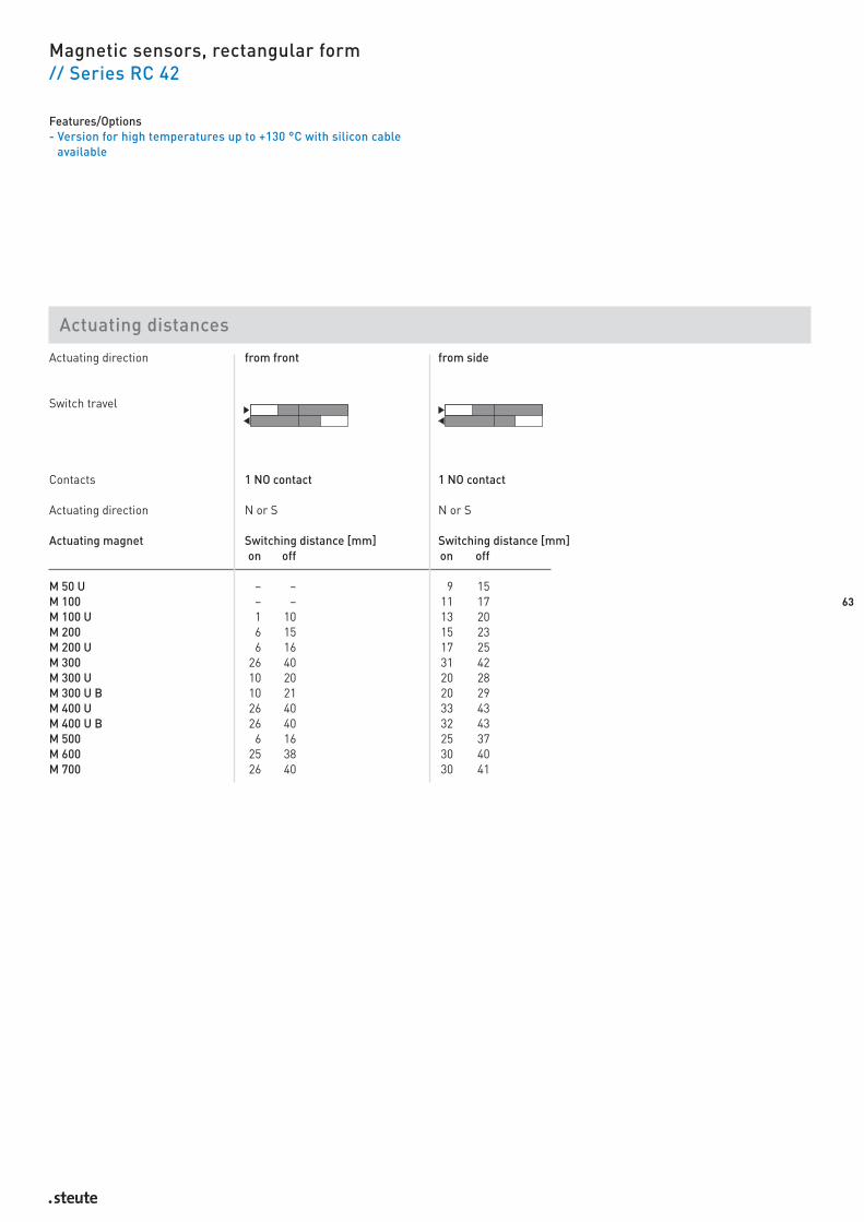
Magnetic sensors, rectangular form// Series RC 42
Features/Options- Thermoplastic enclosure- Long life- 1 Reed contact- Actuation from front and from side- Switching distance up to 33 mm depending on the actuating magnet- With pre-wired cable, cable length 1 metre- Version with doubled switching capacity with tungsten reed
contacts available
Standards IEC/EN 60947-5-1Enclosure glass-fibre reinforced polyamideActuator series M permanent magnetProtection class IP 67 to IEC/EN 60529Contact material rhodium; -W: TungstenSwitching system reed contactsContact types NO contact, change-over contact, bi-stable or
change-over contact latchingTermination lead-free pre-wired cable, PVC H05VV-F or
3-pole connector to DIN 41 524 Cable section 2 x 0.5 mm
2
Cable length 1, 2 orr 5 mSwitching voltage max. 250 VAC/DCSwitching current 1S: 2 A; 1W: 0,5 A; -W: 1 ASwitching capacity 1S: max. 50 VA/ W; 1W: max. 15 VA/ W;
-W: max. 25 VA/ WSwitching frequency max. 200 HzAmbient temperature -10 °C … +80 ºCMechanical life 10
9operations
Electrical life 109
operationsRepeat accuracy ± 0.02 mmResistance to vibrations1S: 20 g, 1W: 10 g
Contact variants: Switch travel/contacts
actuation from side latching
1 NC contact RC 42 1Ö
1 NO contact RC 42 1S RC 42 1Sr
1 change-over contact RC 42 1W RC 42 1Wr
62
63
Magnetic sensors, rectangular form// Series RC 42
Features/Options- Version for high temperatures up to +130 °C with silicon cable
available
Actuating direction from front from side
Switch travel
Contacts 1 NO contact 1 NO contact
Actuating direction N or S N or S
Actuating magnet Switching distance [mm] Switching distance [mm]on off on off
M 50 U – – 9 15M 100 – – 11 17M 100 U 1 10 13 20M 200 6 15 15 23M 200 U 6 16 17 25M 300 26 40 31 42M 300 U 10 20 20 28M 300 U B 10 21 20 29M 400 U 26 40 33 43M 400 U B 26 40 32 43M 500 6 16 25 37M 600 25 38 30 40M 700 26 40 30 41
Actuating distances
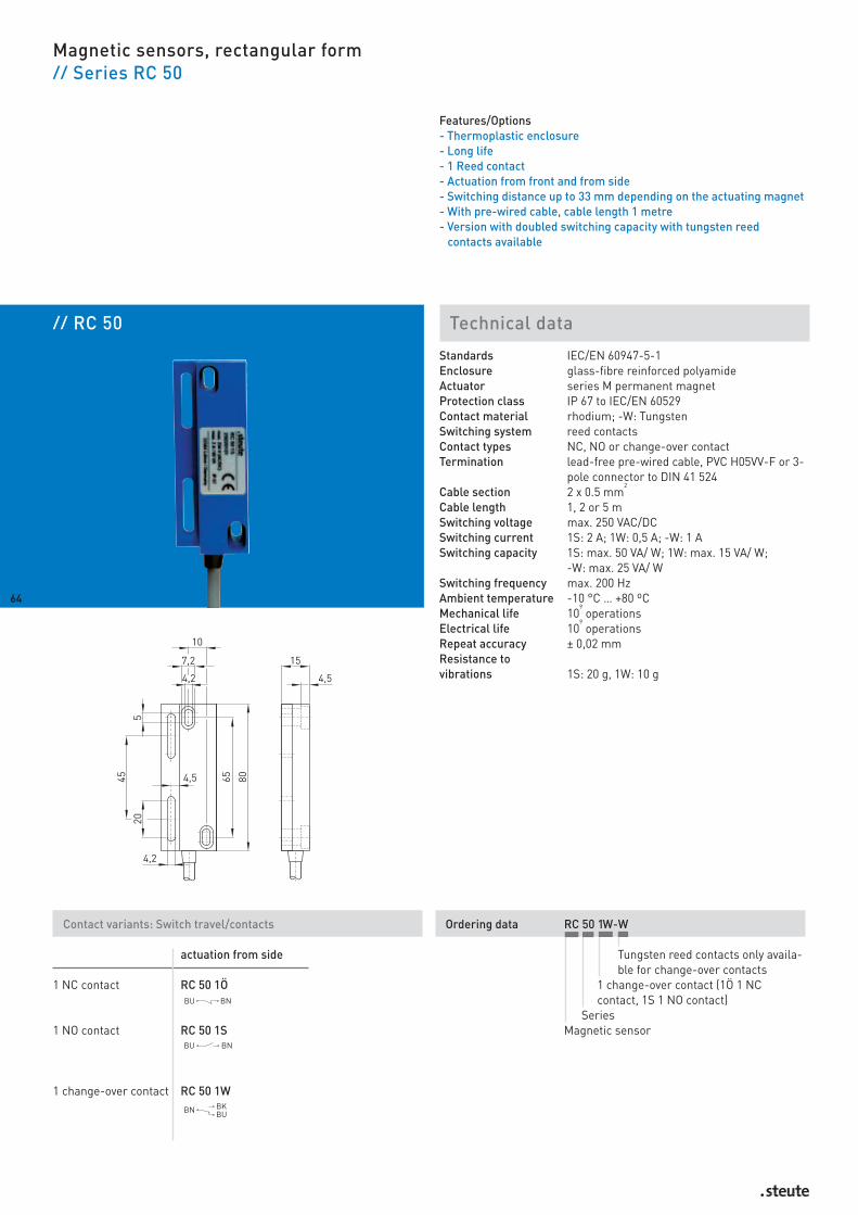
// RC 50 Technical data
Magnetic sensors, rectangular form// Series RC 50
Features/Options- Thermoplastic enclosure- Long life- 1 Reed contact- Actuation from front and from side- Switching distance up to 33 mm depending on the actuating magnet- With pre-wired cable, cable length 1 metre- Version with doubled switching capacity with tungsten reed
contacts available
Standards IEC/EN 60947-5-1Enclosure glass-fibre reinforced polyamideActuator series M permanent magnetProtection class IP 67 to IEC/EN 60529Contact material rhodium; -W: TungstenSwitching system reed contactsContact types NC, NO or change-over contactTermination lead-free pre-wired cable, PVC H05VV-F or 3-
pole connector to DIN 41 524Cable section 2 x 0.5 mm
2
Cable length 1, 2 or 5 mSwitching voltage max. 250 VAC/DCSwitching current 1S: 2 A; 1W: 0,5 A; -W: 1 ASwitching capacity 1S: max. 50 VA/ W; 1W: max. 15 VA/ W;
-W: max. 25 VA/ WSwitching frequency max. 200 HzAmbient temperature -10 °C … +80 ºCMechanical life 10
9operations
Electrical life 109
operationsRepeat accuracy ± 0,02 mmResistance to vibrations 1S: 20 g, 1W: 10 g
Contact variants: Switch travel/contacts
actuation from side
1 NC contact RC 50 1Ö
1 NO contact RC 50 1S
1 change-over contact RC 50 1W
Ordering data RC 50 1W-W
Tungsten reed contacts only availa-ble for change-over contacts
1 change-over contact (1Ö 1 NCcontact, 1S 1 NO contact)
SeriesMagnetic sensor
64

65
Magnetic sensors, rectangular form// Series RC 50
Features/Options- Version for high temperatures up to +130 °C with silicon cable
available
Actuating direction from front from side
Switch travel
Contacts 1 NO contact 1 NO contact
Actuating direction N or S N or S
Actuating magnet Switching distance [mm] Switching distance [mm]on off on off
M 50 U – – 9 12M 100 26 33 10 13M 100 U 1 6 12 15M 200 4 9 15 19M 200 U 4 10 16 20M 300 25 32 30 35M 300 U 10 15 20 23M 300 U B 10 16 20 24M 400 U 25 32 33 37M 400 U B 10 15 31 37M 500 5 11 29 34M 600 24 31 29 34M 700 25 32 29 34
Actuating distances
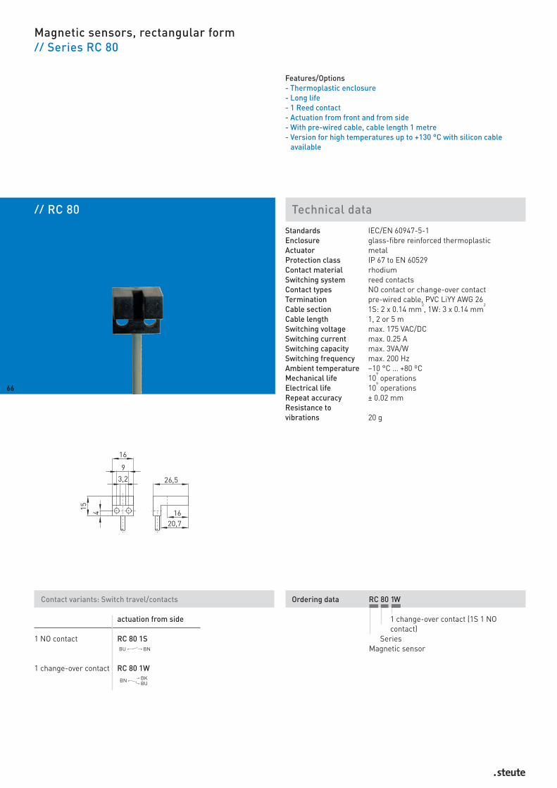
Ordering data RC 80 1W
1 change-over contact (1S 1 NOcontact)
SeriesMagnetic sensor
// RC 80 Technical data
Magnetic sensors, rectangular form// Series RC 80
Features/Options- Thermoplastic enclosure- Long life- 1 Reed contact- Actuation from front and from side- With pre-wired cable, cable length 1 metre- Version for high temperatures up to +130 °C with silicon cable
available
Standards IEC/EN 60947-5-1Enclosure glass-fibre reinforced thermoplasticActuator metalProtection class IP 67 to EN 60529Contact material rhodiumSwitching system reed contactsContact types NO contact or change-over contactTermination pre-wired cable, PVC LiYY AWG 26Cable section 1S: 2 x 0.14 mm
2, 1W: 3 x 0.14 mm
2
Cable length 1, 2 or 5 mSwitching voltage max. 175 VAC/DCSwitching current max. 0.25 ASwitching capacity max. 3VA/WSwitching frequency max. 200 HzAmbient temperature –10 °C … +80 ºCMechanical life 10
9operations
Electrical life 109
operationsRepeat accuracy ± 0.02 mmResistance to vibrations 20 g
Contact variants: Switch travel/contacts
actuation from side
1 NO contact RC 80 1S
1 change-over contact RC 80 1W
66
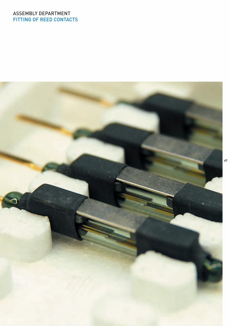
67
ASSEMBLY DEPARTMENTFITTING OF REED CONTACTS

// RC 90 Technical data
Magnetic sensors, rectangular form// Series RC 90
Features/Options- Thermoplastic enclosure- Application on pneumatic cylinders- Long life- 1 Reed contact- Actuation from front and from side- With pre-wired cable, cable length 1 metre
Standards IEC/EN 60947-5-1Enclosure glass-fibre reinforced polyamide PA 6.6Actuator magnetProtection class IP 65 to EN 60529Contact material rhodiumSwitching system reed contactsContact types NO contactTermination pre-wired cable, PVC LiYYCable section 2 x 0.34 mm
2
Cable length 1, 2 oder 5 mSwitching voltage max. 250 VAC/DCSwitching current max. 1 ASwitching capacity max. 100 W/VASwitching frequency max. 200 HzAmbient temperature -10 °C … +80 ºCMechanical life 10
9operations
Electrical life 109
operationsRepeat accuracy ± 0.02 mmResistance to vibrations 20 g
Contact variants: Switch travel/contacts
actuation from side
1 NO contact RC 90 1S
Ordering data RC 90 1S-ST-250VA
Switching capacity 250 VA (30VA)with plug-in connector
1 NO contactSeries
Magnetic sensor
68

Magnetic sensors, rectangular form// Series RC 90, variants
Features/Options- Coupler for magnetic sensors with plug-in connector: Klar +
Beilschmidt- Version for high temperatures up to +130 °C with silicon cable
available- Available with LED for operating voltage indication
// Connector // Connector
69
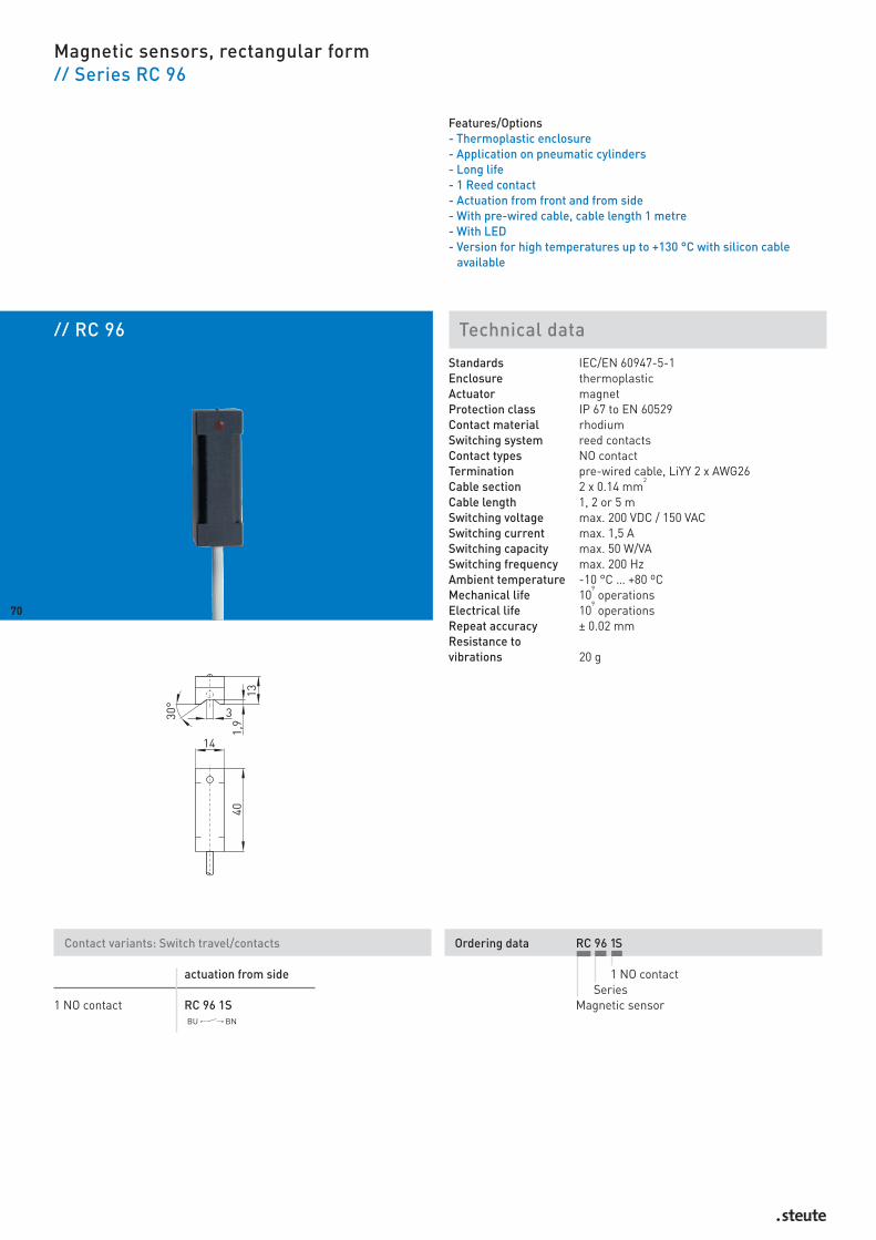
// RC 96 Technical data
Magnetic sensors, rectangular form// Series RC 96
Features/Options- Thermoplastic enclosure- Application on pneumatic cylinders- Long life- 1 Reed contact- Actuation from front and from side- With pre-wired cable, cable length 1 metre- With LED- Version for high temperatures up to +130 °C with silicon cable
available
Standards IEC/EN 60947-5-1Enclosure thermoplasticActuator magnetProtection class IP 67 to EN 60529Contact material rhodiumSwitching system reed contactsContact types NO contactTermination pre-wired cable, LiYY 2 x AWG26Cable section 2 x 0.14 mm
2
Cable length 1, 2 or 5 mSwitching voltage max. 200 VDC / 150 VACSwitching current max. 1,5 ASwitching capacity max. 50 W/VASwitching frequency max. 200 HzAmbient temperature -10 °C … +80 ºCMechanical life 10
9operations
Electrical life 109
operationsRepeat accuracy ± 0.02 mmResistance to vibrations 20 g
Contact variants: Switch travel/contacts
actuation from side
1 NO contact RC 96 1S
Ordering data RC 96 1S
1 NO contactSeries
Magnetic sensor
70
71
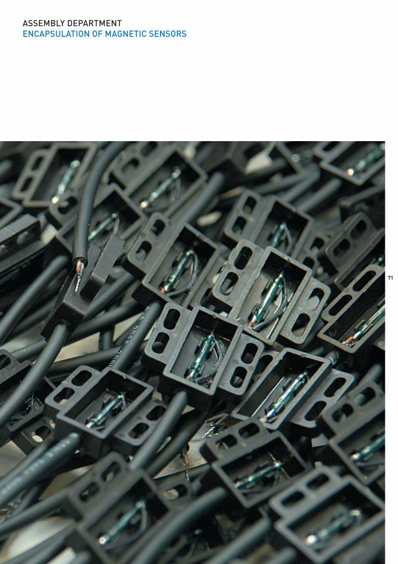
ASSEMBLY DEPARTMENTENCAPSULATION OF MAGNETIC SENSORS
// Actuating magnet M 200 S
72
// Actuating magnet M 200 N U
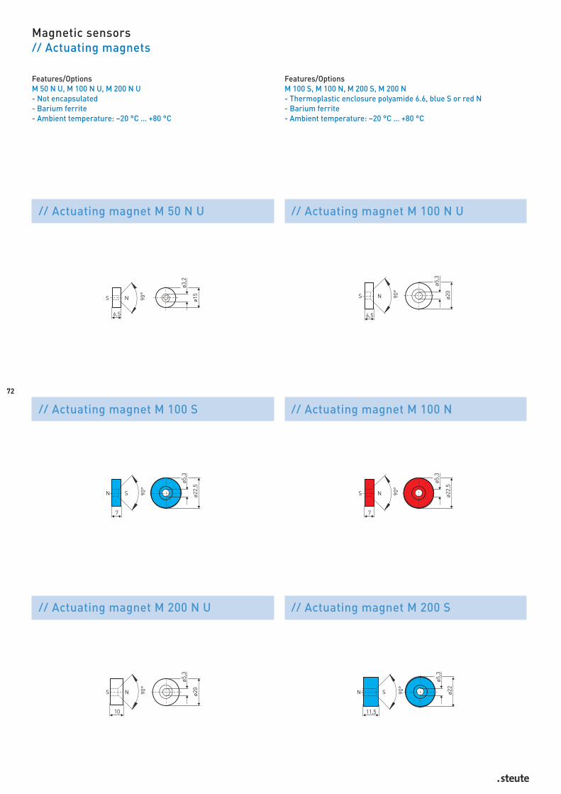
Features/OptionsM 100 S, M 100 N, M 200 S, M 200 N- Thermoplastic enclosure polyamide 6.6, blue S or red N- Barium ferrite- Ambient temperature: –20 °C … +80 °C
Magnetic sensors // Actuating magnets
Features/OptionsM 50 N U, M 100 N U, M 200 N U- Not encapsulated- Barium ferrite- Ambient temperature: –20 °C … +80 °C
// Actuating magnet M 50 N U // Actuating magnet M 100 N U
// Actuating magnet M 100 S // Actuating magnet M 100 N

// Actuating magnet M 300 N
73
// Actuating magnet M 400 N U
Features/OptionsM 200 N, M 300 S, M 300 N- Thermoplastic enclosure polyamide 6.6, blue S or red N- Barium ferrite- Ambient temperature: –20 °C … +80 °C
Magnetic sensors // Actuating magnets
Features/OptionsM 300 N U, M 300 U B, M 400 N U- Not encapsulated- M 300 U: North pole with colour marking (red dot)- Barium ferrite- Ambient temperature: –20 °C … +80 °C
// Actuating magnet M 200 N // Actuating magnet M 300 N U
// Actuating magnet M 300 U B // Actuating magnet M 300 S

74
Features/OptionsM 700 S- Thermoplastic enclosure polyamide 6.6, blue S- Barium ferrite- Ambient temperature: –20 °C … +80 °C
M 500- Thermoplastic enclosure glass-fibre reinforced polyamide- Barium ferrite- Ambient temperature: –20 °C … +80 °C
Magnetic sensors // Actuating magnets
Features/OptionsM 400 U B, M 20 U- Not encapsulated- Barium ferrite- Ambient temperature: –20 °C … +80 °C
M 700 N- Thermoplastic enclosure polyamide 6.6, red N- Barium ferrite- Ambient temperature: –20 °C … +80 °C
// Actuating magnet M 400 U B // Actuating magnet M 700 S
// Actuating magnet M 700 N
// Actuating magnet M 20 U
// Actuating magnet M 500

75
Explanation of the switch travel diagrams
Contact openContact closed
Explanation of symbols
X1-X2 NC contactX3-X4 NO contactX5-X6 Overlapping contacts
Colour code designation to DIN IEC 757
BK blackBN brownBU blueGN greenGY greyOG orangePK pinkRD redTQ turquoiseVI violetWH whiteYE yellow
j A/F
Directive-compliant, see Declaration of Conformity
Ie Rated operating current
Ithe Thermal test current rating
sao Assured operation distance
sar Assured release distance
Ue Rated operating voltage
Ui Rated insulation voltage
Uimp Rated impulse withstand voltage
Errata and technical modifications reserved.
j
01.2
6.04
71/1
1813
12/1
0.20
07/2
000
wd
Beside safety, magnetic safetyand magnetic sensors steute de-signs and produces emergencypull-wire, pull-wire, belt-align-ment and slack-wire,safety, position, foot, door handleswitches and industrial switch-gear with radio technology, aswell as command devices for in-dustrial applications of controltechnology. In addition, switch-gear for explosion protection thatare applied where flammable
atmospheres can occur – e.g. Exposition switches, Ex pull-wireswitches, Ex safety switches andsolenoid interlocks, as well as Exmagnetic sensors. Furthermoresteute boasts a wide program ofcontrol devices for complex andcritical applications for medicalequipment.
steute Schaltgeräte GmbH & Co. KG Brückenstraße 9132584 Löhne, GermanyPhone + 49 (0) 57 31 7 45-0 Telefax + 49 (0) 57 31 7 45-200 E-mail [email protected]