Embed Size (px)
Citation preview
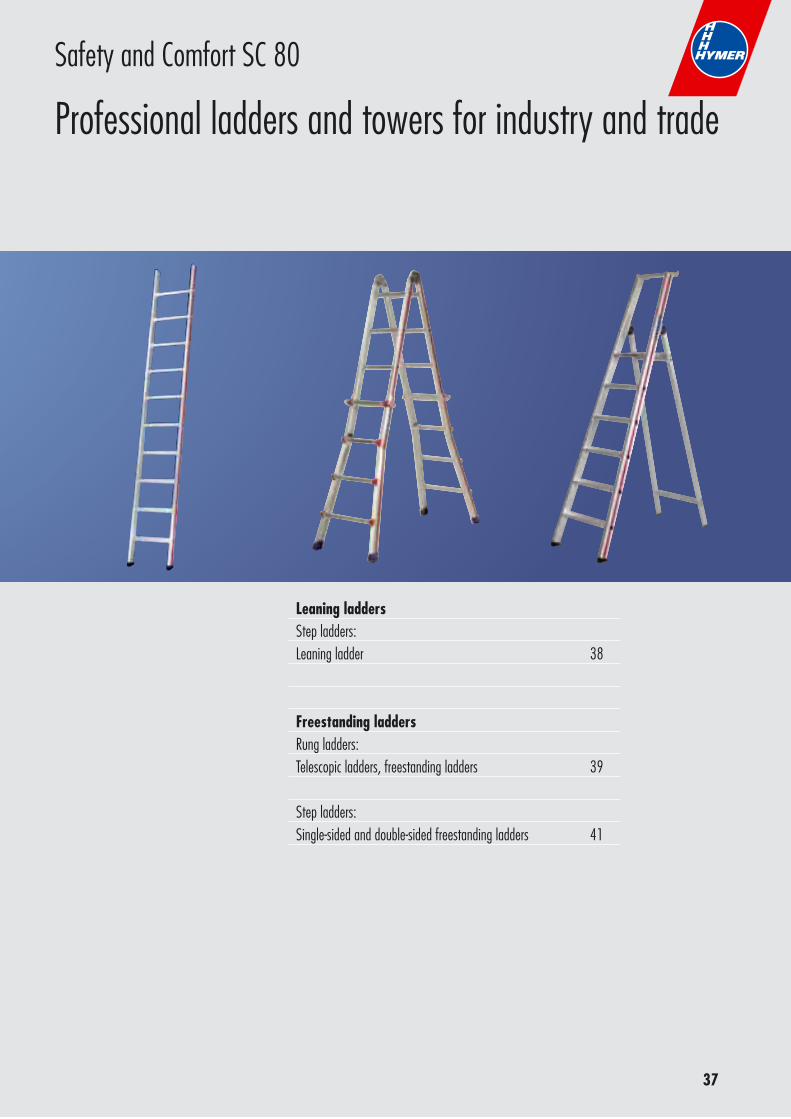
Professional ladders and towers for industry and trade
Safety and Comfort – made in Germany
The ladder with the red stripe
02-2011
YOU CAN BE COMPLETELY SURETHAT YOU CAN RELY ON HYMER-LEICHTMETALLBAU FOR
Hymer safetyAll products in this catalogue are still „made in Germany“. In addition, all products meet the requirements on enhan-ced safety in the use of ladders and scaffolds.
Certain to be there for the customerHymer-Leichtmetallbau has been a reliable and helpful partner at its customers‘ side for over 45 years and knows their needs inside out.
The origin of secure qualityHigh functionality, long service life, great reliability and safety, even down to the smallest detail – these are the standards by which Hymer-Leichtmetallbau products are measured time and again
Company securityHymer-Leichtmetallbau is a traditionally-run German family business with shareholders who are loyal to the business, its quality products, employees and customers.
3
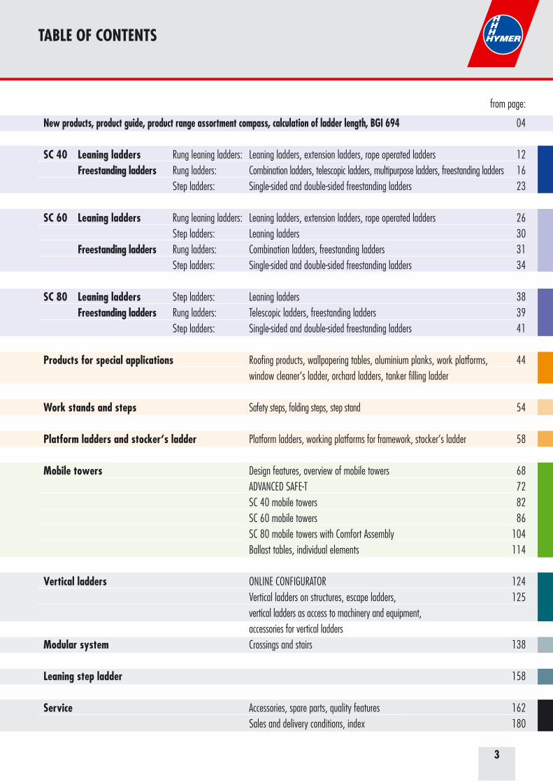
TABLE OF CONTENTS
from page:
New products, product guide, product range assortment compass, calculation of ladder length, BGI 694 04 SC 40 Leaning ladders Rung leaning ladders: Leaning ladders, extension ladders, rope operated ladders 12 Freestanding ladders Rung ladders: Combination ladders, telescopic ladders, multipurpose ladders, freestanding ladders 16 Step ladders: Single-sided and double-sided freestanding ladders 23
SC 60 Leaning ladders Rung leaning ladders: Leaning ladders, extension ladders, rope operated ladders 26 Step ladders: Leaning ladders 30 Freestanding ladders Rung ladders: Combination ladders, freestanding ladders 31 Step ladders: Single-sided and double-sided freestanding ladders 34
SC 80 Leaning ladders Step ladders: Leaning ladders 38 Freestanding ladders Rung ladders: Telescopic ladders, freestanding ladders 39 Step ladders: Single-sided and double-sided freestanding ladders 41
Products for special applications Roofing products, wallpapering tables, aluminium planks, work platforms, 44 window cleaner‘s ladder, orchard ladders, tanker filling ladder
Work stands and steps Safety steps, folding steps, step stand 54
Platform ladders and stocker‘s ladder Platform ladders, working platforms for framework, stocker‘s ladder 58
Mobile towers Design features, overview of mobile towers 68 ADVANCED SAFE-T 72 SC 40 mobile towers 82 SC 60 mobile towers 86 SC 80 mobile towers with Comfort Assembly 104 Ballast tables, individual elements 114
Vertical ladders ONLINE CONFIGURATOR 124 Vertical ladders on structures, escape ladders, 125 vertical ladders as access to machinery and equipment, accessories for vertical laddersModular system Crossings and stairs 138
Leaning step ladder 158
Service Accessories, spare parts, quality features 162 Sales and delivery conditions, index 180
4
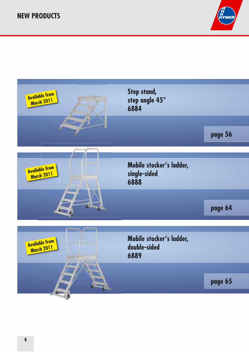
NEW PRODUCTS
Step stand, step angle 45°6884
page 56
Mobile stocker‘s ladder, single-sided6888
page 64
Mobile stocker‘s ladder, double-sided6889
page 65
Available from
March 2011
Available from
March 2011
Available from
March 2011
5
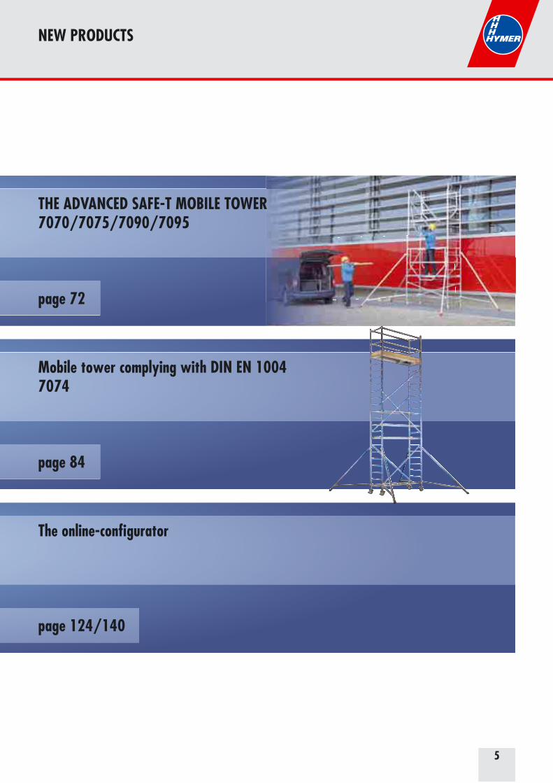
NEW PRODUCTS
THE ADVANCED SAFE-T MOBILE TOWER7070/7075/7090/7095
page 72
Mobile tower complying with DIN EN 10047074
page 84
RRRR
The online-configurator
page 124/140
6
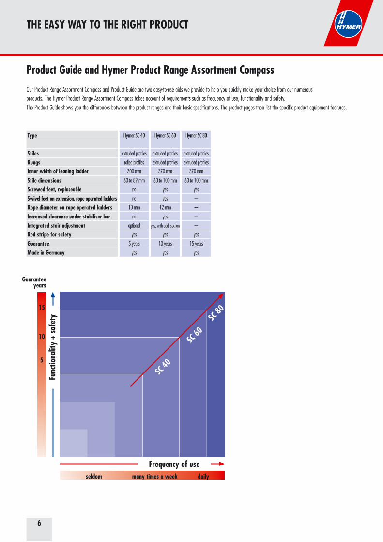
THE EASY WAY TO THE RIGHT PRODUCT
Type
StilesRungs Inner width of leaning ladderStile dimensions Screwed feet, replaceableSwivel feet on extension, rope operated laddersRope diameter on rope operated ladders Increased clearance under stabiliser bar Integrated stair adjustment Red stripe for safety GuaranteeMade in Germany
Hymer SC 40
extruded profiles
rolled profiles
300 mm
60 to 89 mm
no
no
10 mm
no
optional
yes
5 years
yes
Hymer SC 60
extruded profiles
extruded profiles
370 mm
60 to 100 mm
yes
yes
12 mm
yes
yes, with add. section
yes
10 years
yes
Hymer SC 80
extruded profiles
extruded profiles
370 mm
60 to 100 mm
yes
-–
-–
-–
-–
yes
15 years
yes
Product Guide and Hymer Product Range Assortment Compass
Our Product Range Assortment Compass and Product Guide are two easy-to-use aids we provide to help you quickly make your choice from our numerous products. The Hymer Product Range Assortment Compass takes account of requirements such as frequency of use, functionality and safety. The Product Guide shows you the differences between the product ranges and their basic specifications. The product pages then list the specific product equipment features.
seldom many times a week daily
SC 40
SC 60
SC 80
5
10
15
Frequency of use
Func
tiona
lity
+ sa
fety
Guaranteeyears
77
CALCULATION OF LADDER LENGTH
Vertical height in m
75° rung ladders70° rung ladders 68° stepladders 60° steps45° steps
2.00
2.10
2.15
2.20
2.30
2.80
2.50
2.60
2.65
2.70
2.90
3.50
3.00
3.10
3.20
3.25
3.50
4.20
3.50
3.60
3.70
3.80
4.10
4.90
4.00
4.10
4.25
4.35
4.60
5.60
4.50
4.70
4.80
4.90
5.20
5.00
5.20
5.30
5.40
5.80
5.50
5.70
5.85
5.95
6.00
6.20
6.40
6.50
6.50
6.70
6.90
7.00
7.00
7.20
7.40
7.60
7.50
7.80
8.00
8.10
8.00
8.30
8.50
8.60
8.50
8.80
9.00
9.20
9.00
9.30
9.60
9.70
9.50
9.80
10.10
10.30
10.00
10.40
10.60
10.80
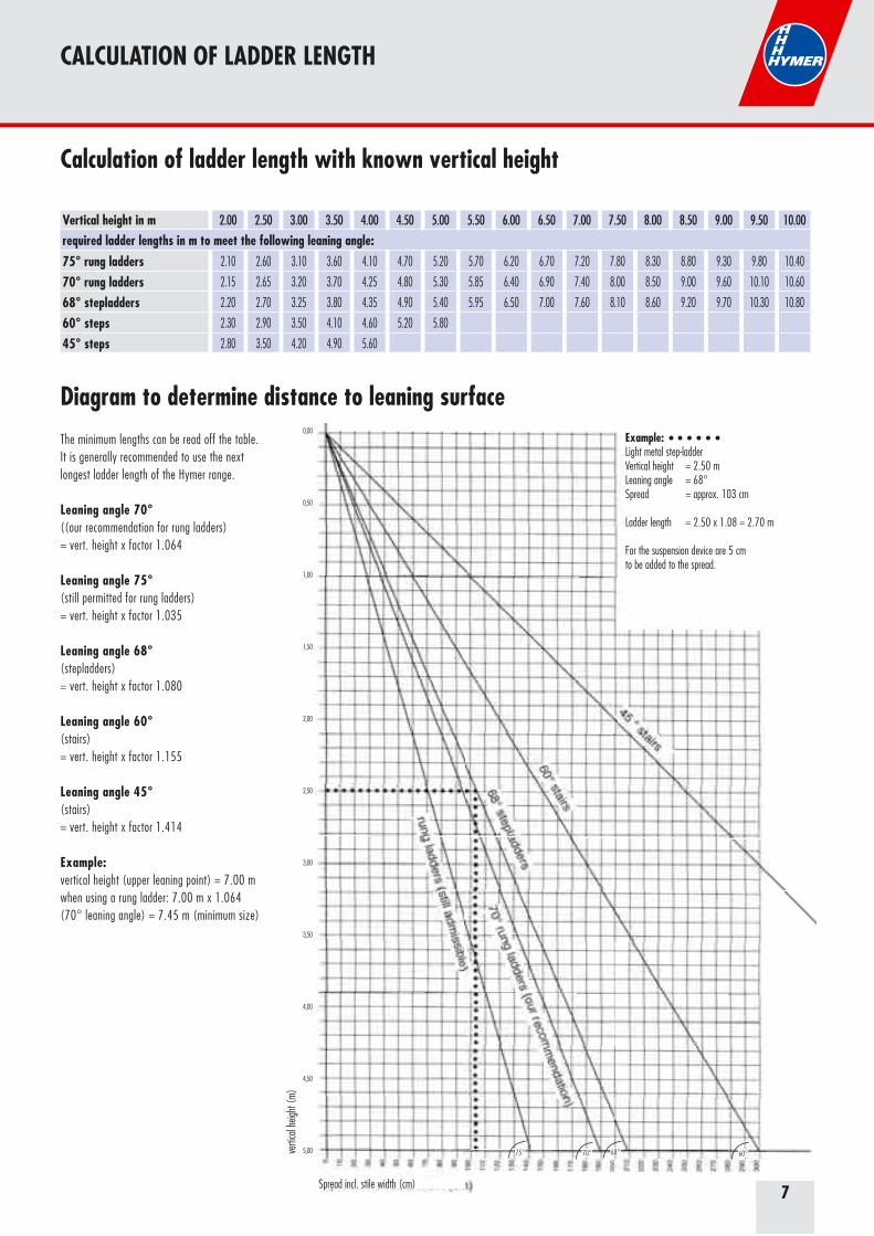
Calculation of ladder length with known vertical height
required ladder lengths in m to meet the following leaning angle:
Diagram to determine distance to leaning surfaceThe minimum lengths can be read off the table.It is generally recommended to use the nextlongest ladder length of the Hymer range.
Leaning angle 70°((our recommendation for rung ladders)= vert. height x factor 1.064
Leaning angle 75°(still permitted for rung ladders)= vert. height x factor 1.035
Leaning angle 68° (stepladders)= vert. height x factor 1.080
Leaning angle 60° (stairs)= vert. height x factor 1.155
Leaning angle 45° (stairs)= vert. height x factor 1.414
Example: vertical height (upper leaning point) = 7.00 mwhen using a rung ladder: 7.00 m x 1.064 (70° leaning angle) = 7.45 m (minimum size)
68°70°75° 60°verti
cal h
eight
(m)
Spread incl. stile width (cm)
Example: Light metal step-ladderVertical height = 2.50 mLeaning angle = 68°Spread = approx. 103 cm
Ladder length = 2.50 x 1.08 = 2.70 m
For the suspension device are 5 cm to be added to the spread.
0,00
0,50
1,00
1,50
2,00
2,50
3,00
3,50
4,00
4,50
5,00
8
FEATURES OF THE SC 40 - SC 60 - SC 80 LADDER RANGES
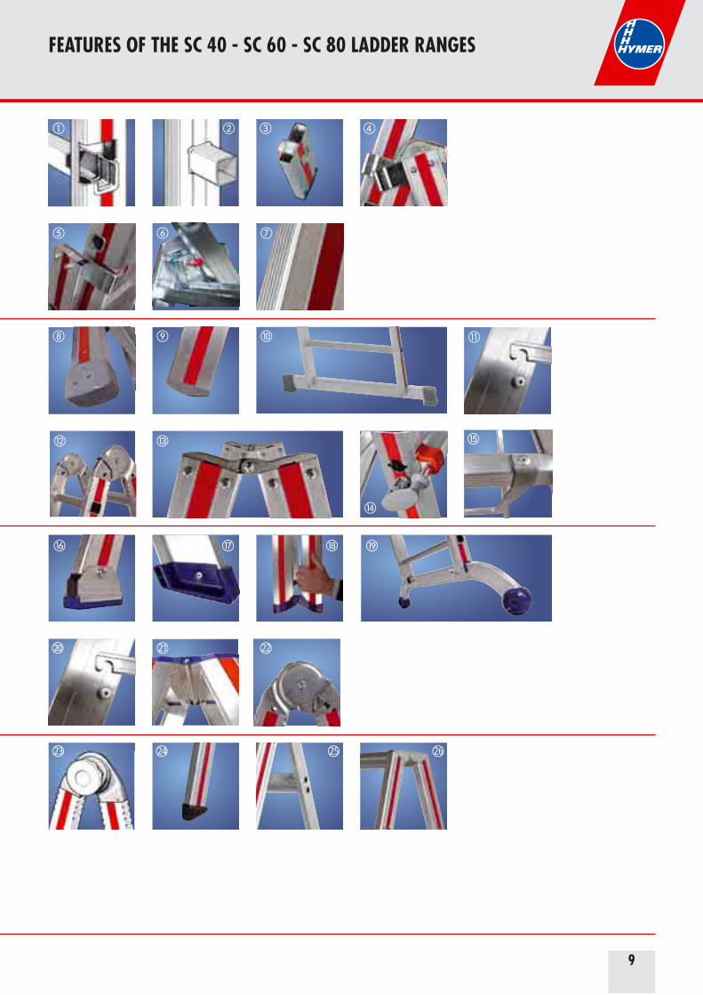
SC 40 - SC 60 - SC 80 features
– Seamless extruded profiles for all stile types �– Robust and shock-proof reinforcement of the corners �– Ergonomically shaped for secure and comfortable grip � – High-quality fittings � – Fittings with plastic slider to protect the material �– Repair-friendly design with bolted joints � – Red side stripe as a warning signal and trademark of Hymer quality �
SC 40 details
– Rounded feet for perfect accommodation of uneven and tilting ground – High quality plastic foot providing slip resistance and great stability – Extra wide stabiliser bar with plastic foot �– Internally mounted stiffening brace, protected in transport, for securing against spreading �– Fully galvanized, easy to use hinges – Hinges are easy to repair and protect against entrapment �– Plastic coated locking elements � – High strength, tear-resistant, UV-resistant nylon straps �
SC 60 details
– Aluminium swivel feet, bolted on and easy to repair, with a large surface for a stable footing �– Wide, slip resistant plastic feet on stepladders � – Transport position protects against trapped fingers �– Comfortable, wide stabiliser bar with 125 mm floor clearance and provided two-part feet for fitting ground hooks �– Double, internally mounted braces with locking latch function for transport and use �– Continuous hinges on 2-sided stepladders– Automatically engaging steel safety hinges
SC 80 details
– High quality double bolt hinge with duplex lock for easy handling of the ladder – Two-component foot, bolted to ease repair – Extremely stable double tube support for single-sided freestanding tread ladders– High strength cast hinges, bolted to ease repair
�21�22
�23�24
�25�26
9
� �� �
� ��
�
��
�
�
�
� �� �
�21 �22
�23 �24 �25 �26
FEATURES OF THE SC 40 - SC 60 - SC 80 LADDER RANGES
1010
HIGHEST STANDARDS WITH HYMER
From BGV D36 to BGI 694
The previous German accident prevention regulation BGV D36 was replaced in 2008by BGI 694 – “Handling instructions for the use of ladders and steps”.It can be downloaded from the homepage of „Verband Deutscher Leiter- und Fahrgerüstehersteller“(VDL) at www.vdl-leitern.de.This catalogue also takes account of the technical information relating to the newdistinction between “reach heights” and “working heights”.
For better understanding and clarity, these differences are describedhere again:
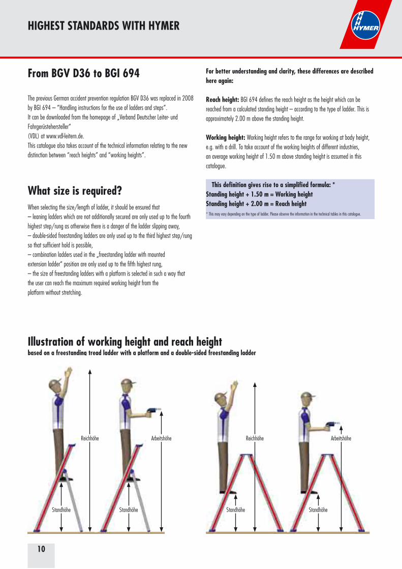
Reach height: BGI 694 defines the reach height as the height which can bereached from a calculated standing height – according to the type of ladder. This isapproximately 2.00 m above the standing height.
Working height: Working height refers to the range for working at body height,e.g. with a drill. To take account of the working heights of different industries,an average working height of 1.50 m above standing height is assumed in thiscatalogue.
This definition gives rise to a simplified formula: *Standing height + 1.50 m = Working heightStanding height + 2.00 m = Reach height* This may vary depending on the type of ladder. Please observe the information in the technical tables in this catalogue.
Illustration of working height and reach height based on a freestanding tread ladder with a platform and a double-sided freestanding ladderg p
Standhöhe Standhöhe Standhöhe Standhöhe
ReichhöheReichhöhe Arbeitshöhe Arbeitshöhe
When selecting the size/length of ladder, it should be ensured that– leaning ladders which are not additionally secured are only used up to the fourthhighest step/rung as otherwise there is a danger of the ladder slipping away,– double-sided freestanding ladders are only used up to the third highest step/rungso that sufficient hold is possible,– combination ladders used in the „freestanding ladder with mountedextension ladder“ position are only used up to the fifth highest rung,– the size of freestanding ladders with a platform is selected in such a way thatthe user can reach the maximum required working height from theplatform without stretching.
What size is required?
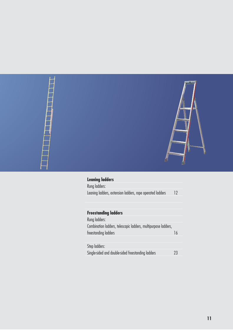
11
Leaning laddersRung ladders: Leaning ladders, extension ladders, rope operated ladders 12
Freestanding laddersRung ladders: Combination ladders, telescopic ladders, multipurpose ladders, freestanding ladders 16
Step ladders:Single-sided and double-sided freestanding ladders 23
12
4011
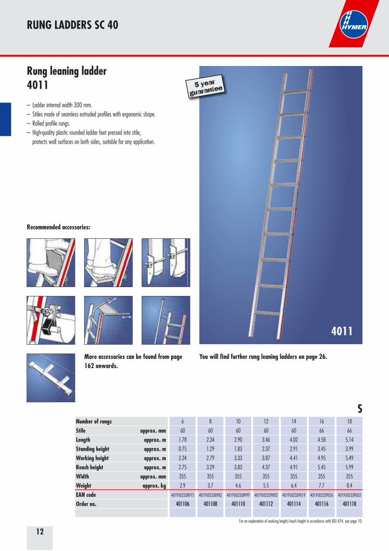
Number of rungsStile approx. mm Length approx. mStanding height approx. mWorking height approx. mReach height approx. mWidth approx. mmWeight approx. kgEAN codeOrder no.
6
60
1.78
0.75
2.24
2.75
355
2.9
4019502338975
401106
8
60
2.34
1.29
2.79
3.29
355
3.7
4019502338982
401108
10
60
2.90
1.83
3.33
3.83
355
4.6
4019502338999
401110
12
60
3.46
2.37
3.87
4.37
355
5.5
4019502339002
401112
14
60
4.02
2.91
4.41
4.91
355
6.4
4019502339019
401114
16
66
4.58
3.45
4.95
5.45
355
7.7
4019502339026
401116
18
66
5.14
3.99
5.49
5.99
355
8.4
4019502339033
401118
Recommended accessories:
S
More accessories can be found from page 162 onwards.
For an explanation of working height/reach height in accordance with BGI 694, see page 10.
Rung leaning ladder4011
– Ladder internal width 300 mm.– Stiles made of seamless extruded profiles with ergonomic shape. – Rolled profile rungs.– High-quality plastic rounded ladder feet pressed into stile, protects wall surfaces on both sides, suitable for any application.
5 year
guarantee
You will find further rung leaning ladders on page 26.
RUNG LADDERS SC 40
13
4046
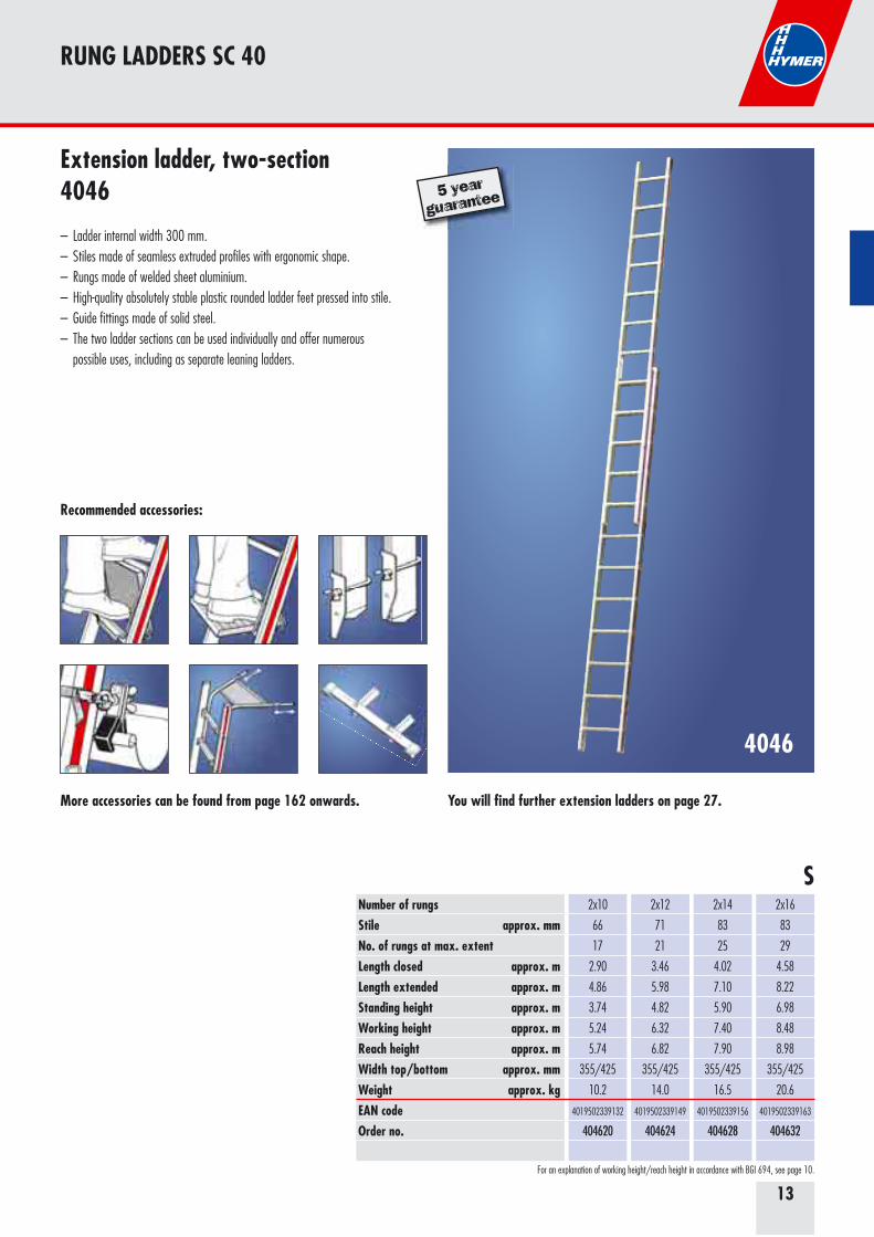
Number of rungsStile approx. mm No. of rungs at max. extentLength closed approx. mLength extended approx. mStanding height approx. mWorking height approx. mReach height approx. mWidth top/bottom approx. mm Weight approx. kgEAN codeOrder no.
2x10
66
17
2.90
4.86
3.74
5.24
5.74
355/425
10.2
4019502339132
404620
2x12
71
21
3.46
5.98
4.82
6.32
6.82
355/425
14.0
4019502339149
404624
2x14
83
25
4.02
7.10
5.90
7.40
7.90
355/425
16.5
4019502339156
404628
2x16
83
29
4.58
8.22
6.98
8.48
8.98
355/425
20.6
4019502339163
404632
Recommended accessories:
S
More accessories can be found from page 162 onwards.
For an explanation of working height/reach height in accordance with BGI 694, see page 10.
Extension ladder, two-section4046
– Ladder internal width 300 mm.– Stiles made of seamless extruded profiles with ergonomic shape. – Rungs made of welded sheet aluminium.– High-quality absolutely stable plastic rounded ladder feet pressed into stile. – Guide fittings made of solid steel.– The two ladder sections can be used individually and offer numerous possible uses, including as separate leaning ladders.
5 year
guarantee
You will find further extension ladders on page 27.
RUNG LADDERS SC 40
14
4051
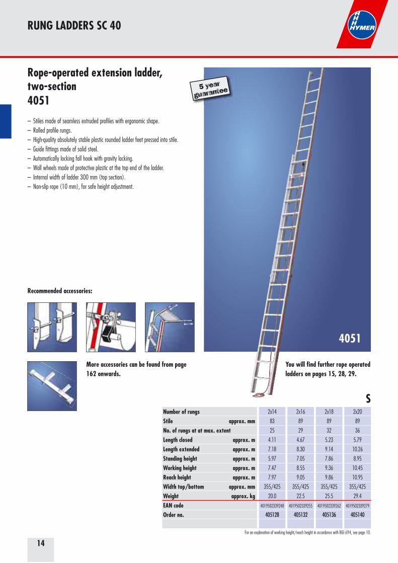
Number of rungsStile approx. mm No. of rungs at at max. extentLength closed approx. mLength extended approx. mStanding height approx. mWorking height approx. mReach height approx. mWidth top/bottom approx. mmWeight approx. kgEAN codeOrder no.
2x14
83
25
4.11
7.18
5.97
7.47
7.97
355/425
20.0
4019502339248
405128
2x16
89
29
4.67
8.30
7.05
8.55
9.05
355/425
22.5
4019502339255
405132
2x18
89
32
5.23
9.14
7.86
9.36
9.86
355/425
25.5
4019502339262
405136
2x20
89
36
5.79
10.26
8.95
10.45
10.95
355/425
29.4
4019502339279
405140
Recommended accessories:
S
More accessories can be found from page 162 onwards.
For an explanation of working height/reach height in accordance with BGI 694, see page 10.
Rope-operated extension ladder, two-section4051
– Stiles made of seamless extruded profiles with ergonomic shape. – Rolled profile rungs.– High-quality absolutely stable plastic rounded ladder feet pressed into stile. – Guide fittings made of solid steel. – Automatically locking fall hook with gravity locking.– Wall wheels made of protective plastic at the top end of the ladder. – Internal width of ladder 300 mm (top section).– Non-slip rope (10 mm), for safe height adjustment.
5 year
guarantee
You will find further rope operated ladders on pages 15, 28, 29.
RUNG LADDERS SC 40
15
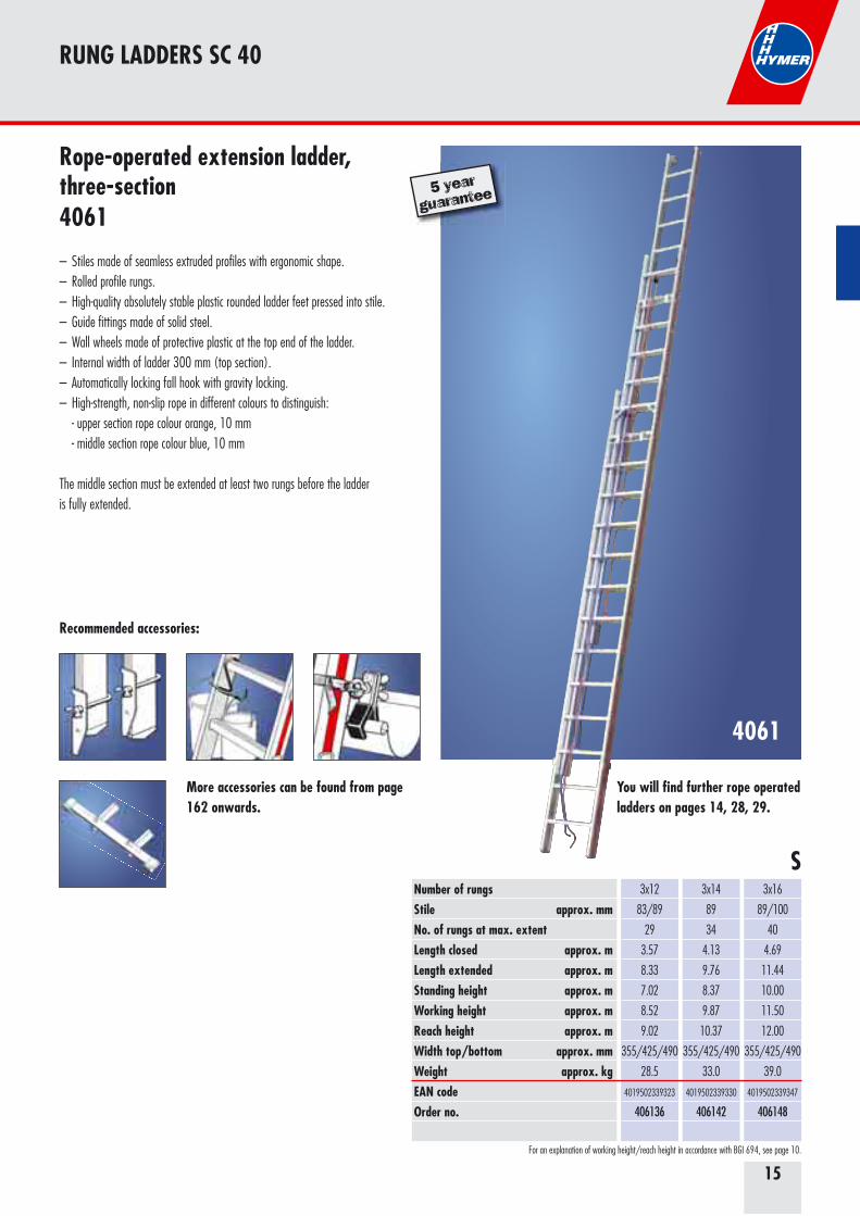
4061
3x12
83/89
29
3.57
8.33
7.02
8.52
9.02
355/425/490
28.5
4019502339323
406136
3x14
89
34
4.13
9.76
8.37
9.87
10.37
355/425/490
33.0
4019502339330
406142
3x16
89/100
40
4.69
11.44
10.00
11.50
12.00
355/425/490
39.0
4019502339347
406148
Number of rungsStile approx. mm No. of rungs at max. extentLength closed approx. mLength extended approx. mStanding height approx. mWorking height approx. mReach height approx. mWidth top/bottom approx. mmWeight approx. kgEAN codeOrder no.
Recommended accessories:
S
More accessories can be found from page 162 onwards.
For an explanation of working height/reach height in accordance with BGI 694, see page 10.
Rope-operated extension ladder, three-section4061
– Stiles made of seamless extruded profiles with ergonomic shape. – Rolled profile rungs.– High-quality absolutely stable plastic rounded ladder feet pressed into stile. – Guide fittings made of solid steel. – Wall wheels made of protective plastic at the top end of the ladder. – Internal width of ladder 300 mm (top section).– Automatically locking fall hook with gravity locking.– High-strength, non-slip rope in different colours to distinguish: - upper section rope colour orange, 10 mm - middle section rope colour blue, 10 mm
The middle section must be extended at least two rungs before the ladder is fully extended.
5 year
guarantee
You will find further rope operated ladders on pages 14, 28, 29.
RUNG LADDERS SC 40
16
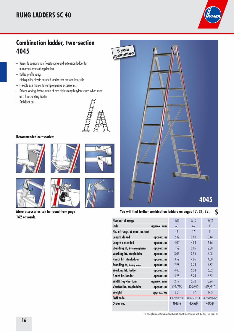
4045
Number of rungsStile approx. mm No. of rungs at max. extentLength closed approx. mLength extended approx. mStanding ht, freestanding ladder approx. mWorking ht, stepladder approx. mReach ht, stepladder approx. mStanding ht, leaning ladder approx. mWorking ht, ladder approx. mReach ht, ladder approx. mWidth top/bottom approx. mm Vertical ht, stepladder approx. mWeight approx. kgEAN codeOrder no.
2x8
60
14
2.32
4.00
1.52
3.02
3.52
2.93
4.43
4.93
2.19
425/715
9.3
4019502339101
404516
2x10
66
17
2.88
4.84
2.05
3.55
4.05
3.74
5.24
5.74
2.72
425/910
11.7
4019502339118
404520
2x12
71
21
3.44
5.96
2.58
4.08
4.58
4.82
6.32
6.82
3.24
425/910
14.3
4019502339125
404524
Recommended accessories:
SMore accessories can be found from page 162 onwards.
For an explanation of working height/reach height in accordance with BGI 694, see page 10.
Combination ladder, two-section4045
– Versatile combination freestanding and extension ladder for numerous areas of application. – Rolled profile rungs.– High-quality plastic rounded ladder feet pressed into stile. – Flexible use thanks to comprehensive accessories. – Safety locking device made of two high-strength nylon straps when used as a freestanding ladder. – Stabiliser bar.
5 year
guarantee
You will find further combination ladders on pages 17, 31, 32.
RUNG LADDERS SC 40
17
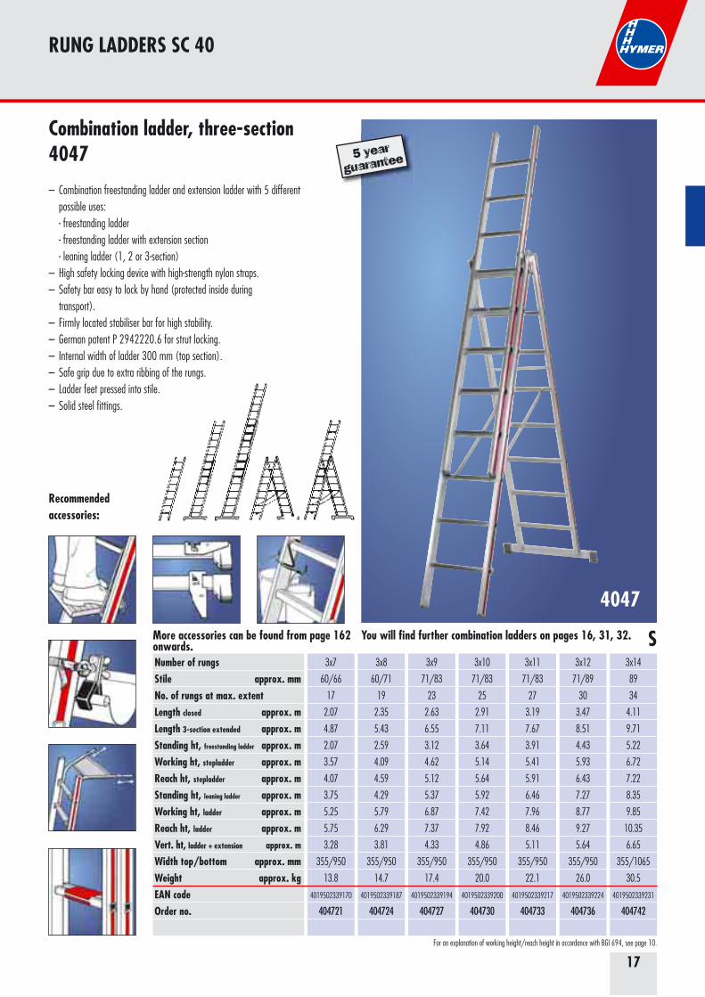
4047
Number of rungsStile approx. mm No. of rungs at max. extentLength closed approx. mLength 3-section extended approx. mStanding ht, freestanding ladder approx. mWorking ht, stepladder approx. mReach ht, stepladder approx. mStanding ht, leaning ladder approx. mWorking ht, ladder approx. mReach ht, ladder approx. mVert. ht, ladder + extension approx. m
Width top/bottom approx. mmWeight approx. kgEAN codeOrder no.
3x7
60/66
17
2.07
4.87
2.07
3.57
4.07
3.75
5.25
5.75
3.28
355/950
13.8
4019502339170
404721
3x8
60/71
19
2.35
5.43
2.59
4.09
4.59
4.29
5.79
6.29
3.81
355/950
14.7
4019502339187
404724
3x9
71/83
23
2.63
6.55
3.12
4.62
5.12
5.37
6.87
7.37
4.33
355/950
17.4
4019502339194
404727
3x10
71/83
25
2.91
7.11
3.64
5.14
5.64
5.92
7.42
7.92
4.86
355/950
20.0
4019502339200
404730
3x11
71/83
27
3.19
7.67
3.91
5.41
5.91
6.46
7.96
8.46
5.11
355/950
22.1
4019502339217
404733
3x12
71/89
30
3.47
8.51
4.43
5.93
6.43
7.27
8.77
9.27
5.64
355/950
26.0
4019502339224
404736
3x14
89
34
4.11
9.71
5.22
6.72
7.22
8.35
9.85
10.35
6.65
355/1065
30.5
4019502339231
404742
Recommended accessories:
SMore accessories can be found from page 162 onwards.
For an explanation of working height/reach height in accordance with BGI 694, see page 10.
Combination ladder, three-section4047
– Combination freestanding ladder and extension ladder with 5 different possible uses: - freestanding ladder - freestanding ladder with extension section - leaning ladder (1, 2 or 3-section)– High safety locking device with high-strength nylon straps.– Safety bar easy to lock by hand (protected inside during transport).– Firmly located stabiliser bar for high stability. – German patent P 2942220.6 for strut locking.– Internal width of ladder 300 mm (top section).– Safe grip due to extra ribbing of the rungs.– Ladder feet pressed into stile.– Solid steel fittings.
5 year
guarantee
You will find further combination ladders on pages 16, 31, 32.
RUNG LADDERS SC 40
18
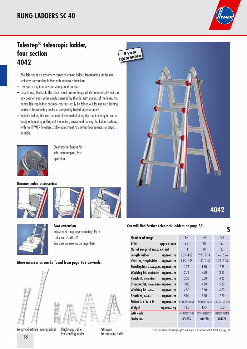
4042
Number of rungsStile approx. mm No. of rungs at max. extentLength ladder approx. mVert. ht, stepladder approx. mStanding ht, freestanding ladder approx. mWorking ht, stepladder approx. mReach ht, stepladder approx. mStanding ht, leaning ladder approx. mWorking ht, ladder approx. mReach ht, ladder approx. mFolded L x W x H approx. mWeight approx. kgEAN codeOrder no.
4x4
60
14
2.35 - 4.02
1.15 - 1.95
1.26
2.76
3.26
3.00
4.50
5.00
1.20 x 0.55 x 0.20
13.0
4019502339385
404216
4x5
60
18
2.90 - 5.14
1.40 - 2.49
1.80
3.30
3.80
4.10
5.60
6.10
1.50 x 0.65 x 0.20
15.5
4019502339392
404220
4x6
60
22
3.46 - 6.26
1.70 - 3.03
2.35
3.85
4.35
5.20
6.70
7.20
1.80 x 0.70 x 0.20
18.0
4019502339408
404224
Foot extensionadjustment range approximately 45 cmOrder no. 0050302See also accessories on page 166.
Recommended accessories:
S
More accessories can be found from page 162 onwards.
For an explanation of working height/reach height in accordance with BGI 694, see page 10.
Telestep® telescopic ladder,four section4042
– The Telestep is an extremely compact leaning ladder, freestanding ladder and stairway freestanding ladder with numerous functions.– Low space requirements for storage and transport.– Easy to use, thanks to the robust steel bracket hinge which automatically locks in any position and can be easily operated by thumb; With a press of the lever, the handy Telestep ladder package can thus easily be folded out for use as a leaning ladder or freestanding ladder or completely folded together again. – Reliable locking devices made of plastic-coated steel; the required length can be easily obtained by pulling out the locking device and moving the ladder sections, with the HYMER Telestep, stable adjustment to uneven floor surfaces or steps is possible.
Steel bracket hinges for safe, non-trapping, fast operation
Height-adjustable freestanding ladder
Stairway freestanding ladder
Length-adjustable leaning ladder
5 year
guarantee
You will find further telescopic ladders on page 39.
RUNG LADDERS SC 40

19
4043
Number of rungsStile approx. mm Length ladder approx. mVertical ht, stepladder approx. mWorking platf. L x H approx. mStanding ht, freestanding ladder approx. mWorking ht, stepladder approx. mReach ht. stepladder approx. mStanding ht, leaning ladder approx. mWorking ht, ladder approx. mReach ht, ladder approx. mFolded L x W x H approx. mWeight approx. kgEAN codeOrder no.
4x3
60
3.47
1.70
1.70 x 0.90
1.15
2.65
3.15
2.50
4.00
4.50
0.90 x 0.70 x 0.30
12.4
4019502339354
404312
4x4
60
4.59
2.25
not permitted
1.70
3.20
3.70
3.60
5.10
5.60
1.20 x 0.80 x 0.30
14.6
4019502339361
404316
4x5
60
5.71
2.70
not permitted
2.25
3.75
4.25
4.70
6.20
6.70
1.50 x 1.00 x 0.30
16.8
4019502339378
404320
* not permitted as work platform from size 4x4
* *
Recommended accessories:
S
More accessories can be found from page 162 onwards.
For an explanation of working height/reach height in accordance with BGI 694, see page 10.
Multipurpose ladder4043
– Universal multipurpose ladder with six safety hinges, which automatically lock in every position. – For use as a freestanding ladder, leaning ladder, work platform and stairway work platform (with boards for size 4x3). – Rungs made of welded sheet aluminium.– High-quality stable plastic rounded ladder feet pressed into stile.
Note: Only to be used as a working platform with a board.
Steel bracket hinges for safe, non-trapping, fast operation
Platform (board) for 4043Order no. 0079639See also accessories on page 169.
5 year
guarantee
RUNG LADDERS SC 40
20
4023
Number of rungsStile approx. mm Length approx. mVert. ht, stepladder approx. mStanding height approx. mWorking height approx. mReach height approx. mWidth top/bottom approx. mmWidth between stiles approx. mWeight approx. kgEAN codeOrder no.
2x5
60
1.47
1.45
1.00
2.50
3.00
340/505
0.95
5.1
4019502339040
402310
2x6
60
1.75
1.70
1.30
2.80
3.30
340/535
1.15
6.1
4019502339057
402312
2x7
60
2.05
1.95
1.55
3.05
3.55
340/565
1.25
7.3
4019502339064
402314
2x8
60
2.33
2.25
1.80
3.30
3.80
340/595
1.45
8.4
4019502339071
402316
2x10
60
2.88
2.75
2.35
3.85
4.35
340/655
1.85
10.9
4019502339088
402320
2x12
60
3.44
3.25
2.90
4.40
4.90
340/715
2.05
13.6
4019502339095
402324
Recommended accessories:
S
S
More accessories can be found from page 162 onwards.
For an explanation of working height/reach height in accordance with BGI 694, see page 10.
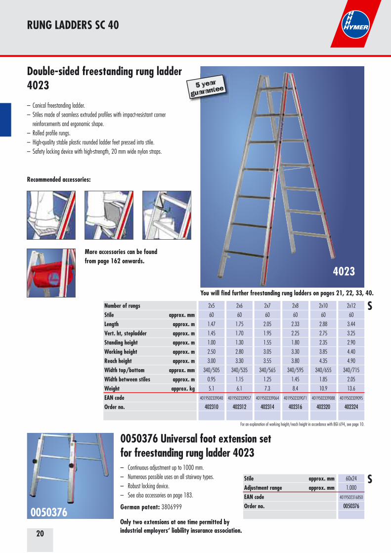
Double-sided freestanding rung ladder4023
– Conical freestanding ladder. – Stiles made of seamless extruded profiles with impact-resistant corner reinforcements and ergonomic shape. – Rolled profile rungs.– High-quality stable plastic rounded ladder feet pressed into stile. – Safety locking device with high-strength, 20 mm wide nylon straps.
0050376 Universal foot extension setfor freestanding rung ladder 4023– Continuous adjustment up to 1000 mm.– Numerous possible uses on all stairway types.– Robust locking device.– See also accessories on page 183.
German patent: 3806999 0050376
Only two extensions at one time permitted by industrial employers‘ liability insurance association.
Stile approx. mmAdjustment range approx. mm EAN code Order no.
60x24
1.000
4019502316850
0050376
5 year
guarantee
You will find further freestanding rung ladders on pages 21, 22, 33, 40.
RUNG LADDERS SC 40
21
0053440/0053441
4123
Number of rungsStile approx. mm Length* approx. mVert. ht, stepladder* approx. mStanding height* approx. mWorking height* approx. mReach height * approx. mWidth top/bottom* approx. mmWidth between stiles* approx. mWeight approx. kgEAN codeOrder no.
2x5
60
1.47
1.45
1.10
2.60
3.10
340/505
0.95
12.0
4019502339286
412310
2x6
60
1.75
1.70
1.35
2.85
3.35
340/535
1.15
12.8
4019502339293
412312
2x7
60
2.05
1.95
1.65
3.15
3.65
340/565
1.25
13.8
4019502339309
412314
2x8
60
2.35
2.25
1.90
3.40
3.90
340/595
1.45
15.0
4019502339316
412316
* Dimensions without foot extensions
Recommended accessories:
S
More accessories can be found from page 162 onwards.
For an explanation of working height/reach height in accordance with BGI 694, see page 10.
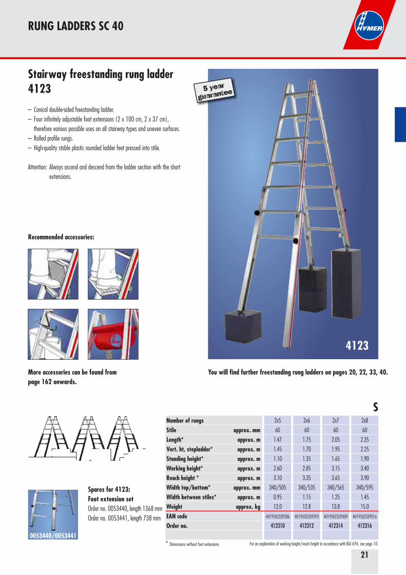
Stairway freestanding rung ladder4123
– Conical double-sided freestanding ladder. – Four infinitely adjustable foot extensions (2 x 100 cm, 2 x 37 cm), therefore various possible uses on all stairway types and uneven surfaces.– Rolled profile rungs.– High-quality stable plastic rounded ladder feet pressed into stile.
Attention: Always ascend and descend from the ladder section with the short extensions.
5 year
guarantee
You will find further freestanding rung ladders on pages 20, 22, 33, 40.
Spares for 4123: Foot extension setOrder no. 0053440, length 1368 mmOrder no. 0053441, length 738 mm
RUNG LADDERS SC 40
22
7-1410
Number of rungsLength approx. mVert. ht, stepladder approx. mStanding height approx. mWorking height approx. mReach height approx. mWidth between stiles approx. mWeight approx. kgEAN codeOrder no.
2x4
1.24
1.18
0.80
2.30
2.80
490
7.0
4019502326217
7141008
2x5
1.52
1.45
1.10
2.60
3.10
520
8.0
4019502326224
7141010
2x6
1.80
1.70
1.35
2.85
3.35
550
10.0
4019502326231
7141012
2x7
2.08
2.00
1.65
3.15
3.65
580
11.0
4019502326248
7141014
2x8
2.36
2.25
1.90
3.40
3.90
610
13.0
4019502326255
7141016
2x10
2.92
2.75
2.45
3.95
4.45
670
17.0
4019502326279
7141020
2x12
3.48
3.30
3.00
4.50
5.00
730
25.0
4019502330849
7141024
S
For an explanation of working height/reach height in accordance with BGI 694, see page 10.
Recommended accessories:
More accessories can be found from page 162 onwards.
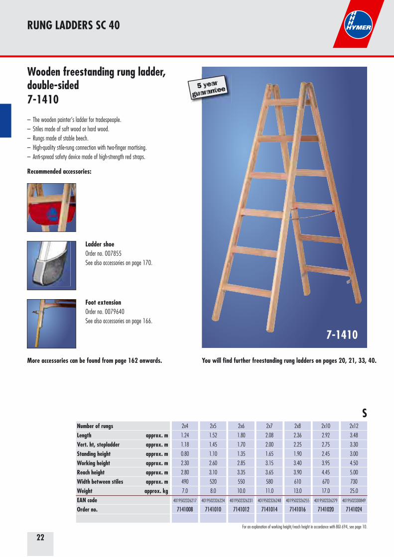
Wooden freestanding rung ladder, double-sided7-1410
– The wooden painter‘s ladder for tradespeople. – Stiles made of soft wood or hard wood.– Rungs made of stable beech. – High-quality stile-rung connection with two-finger mortising. – Anti-spread safety device made of high-strength red straps.
5 year
guarantee
You will find further freestanding rung ladders on pages 20, 21, 33, 40.
Ladder shoeOrder no. 007855See also accessories on page 170.
Foot extensionOrder no. 0079640See also accessories on page 166.
RUNG LADDERS SC 40
23
4026
Number of stepsStile approx. mm Length approx. mVert. height to platform approx. mWorking height approx. mReach height approx. mTotal vert. height approx. mWidth approx. mmWidth between stiles approx. mWeight approx. kgEAN codeOrder no.
3
55
1.37
0.65
2.15
2.65
1.25
415
0.70
4.0
4019502339477
402603
4
55
1.62
0.88
2.38
2.88
1.48
440
0.85
4.7
4019502339484
402604
5
55
1.87
1.11
2.61
3.11
1.71
465
1.00
5.4
4019502339491
402605
6
55
2.12
1.35
2.85
3.35
1.95
495
1.15
6.1
4019502339507
402606
7
55
2.36
1.58
3.08
3.58
2.18
520
1.30
6.8
4019502339514
402607
8
55
2.61
1.80
3.30
3.80
2.40
545
1.50
7.6
4019502339521
402608
Anti-slip feet Covered steel hinge Step width 80 mm S
For an explanation of working height/reach height in accordance with BGI 694, see page 10.
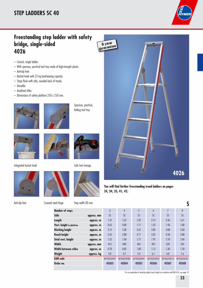
Freestanding step ladder with safety bridge, single-sided4026
– Conical, single ladder.– With spacious, practical tool tray made of high-strength plastic.– Anti-slip feet.– Bucket hook with 25 kg load-bearing capacity.– Steps flush with stile, rounded back of treads.– Versatile.– Anodised stiles.– Dimensions of safety platform 250 x 250 mm.
5 year
guarantee
You will find further freestanding tread ladders on pages 24, 34, 35, 41, 42.
Spacious, practical,folding tool tray
Integrated bucket hook Safe tool storage
STEP LADDERS SC 40
24
4024
STEP LADDERS SC 40
Number of stepsStile approx. mm Length approx. mStanding height approx. mWorking height approx. mReach height approx. mTotal vert. height approx. mWidth approx. mmWidth between stiles approx. mWeight approx. kgEAN codeOrder no.
2x3
55
0.78
0.69
2.19
2.69
0.70
410
0.75
3.6
4019502339415
402406
2x4
55
1.03
0.88
2.38
2.88
0.90
435
0.90
4.5
4019502339422
402408
2x5
55
1.28
1.12
2.62
3.12
1.15
460
1.10
5.5
4019502339439
402410
2x6
55
1.53
1.34
2.84
3.34
1.38
485
1.30
6.7
4019502339446
402412
2x7
55
1.79
1.58
3.08
3.58
1.61
510
1.50
8.0
4019502339453
402414
2x8
55
2.02
1.81
3.31
3.81
1.84
540
1.65
8.8
4019502339460
402416
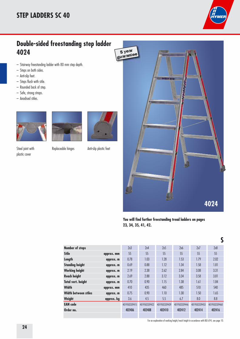
Steel joint withplastic cover
Replaceable hinges Anti-slip plastic feet
S
For an explanation of working height/reach height in accordance with BGI 694, see page 10.
Double-sided freestanding step ladder4024
– Stairway freestanding ladder with 80 mm step depth.– Steps on both sides.– Anti-slip feet.– Steps flush with stile.– Rounded back of step.– Safe, strong straps.– Anodised stiles.
5 year
guarantee
You will find further freestanding tread ladders on pages 23, 34, 35, 41, 42.
25
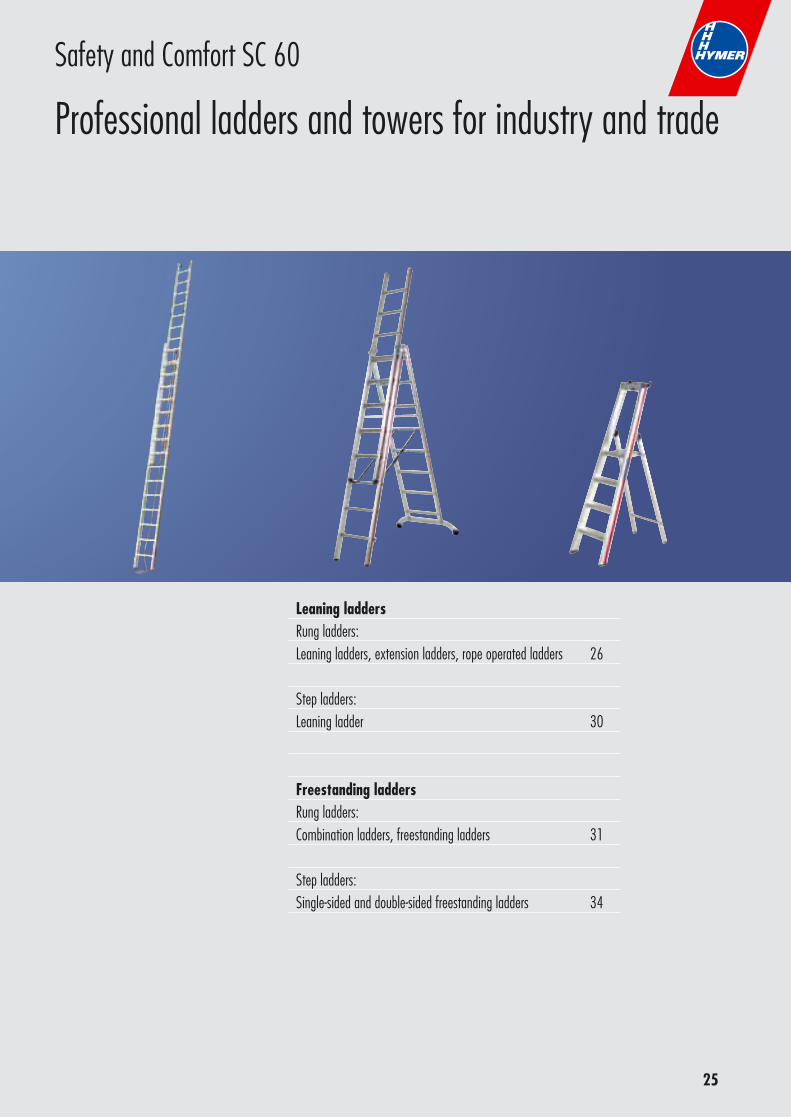
Leaning ladders Rung ladders: Leaning ladders, extension ladders, rope operated ladders 26
Step ladders:Leaning ladder 30
Freestanding laddersRung ladders: Combination ladders, freestanding ladders 31
Step ladders: Single-sided and double-sided freestanding ladders 34
Safety and Comfort SC 60
Professional ladders and towers for industry and trade
26
6011
RUNG LADDERS SC 60
Number of rungsStile approx. mm Length approx. mStanding height approx. mWorking height approx. mReach height approx. mWidth approx. mmWeight approx. kgEAN codeOrder no.
9
60
2.78
1.64
3.14
3.64
425
4.8
4019502338265
601109
10
60
3.06
1.91
3.41
3.91
425
5.3
4019502338272
601110
12
60
3.62
2.45
3.95
4.45
425
6.2
4019502338296
601112
14
60
4.18
2.99
4.49
4.99
425
7.1
4019502338302
601114
16
66
4.75
3.53
5.03
5.53
425
8.1
4019502338319
601116
18
71
5.30
4.07
5.57
6.07
425
8.9
4019502338326
601118
20
71
5.86
4.62
6.12
6.62
425
10.6
4019502338333
601120
22
71
6.42
5.16
6.66
7.16
425
11.6
4019502338340
601122
6
60
1.95
0.83
2.33
2.83
425
3.5
4019502338234
601106
7
60
2.22
1.10
2.60
3.10
425
3.9
4019502338241
601107
8
60
2.50
1.37
2.87
3.37
425
4.3
4019502338258
601108
Recommended accessories:
S
More accessories can be found from page 162 onwards.
For an explanation of working height/reach height in accordance with BGI 694, see page 10.
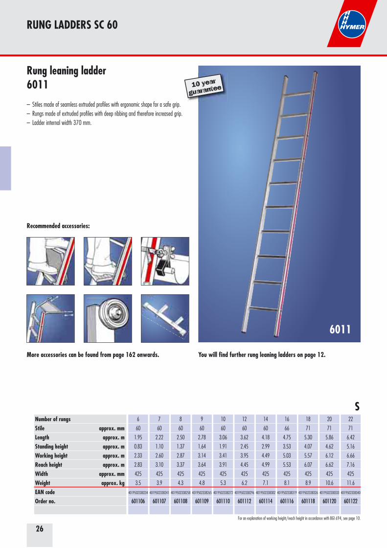
Rung leaning ladder6011
– Stiles made of seamless extruded profiles with ergonomic shape for a safe grip. – Rungs made of extruded profiles with deep ribbing and therefore increased grip.– Ladder internal width 370 mm.
10 year
guarantee
You will find further rung leaning ladders on page 12.
27
RUNG LADDERS SC 60
6046
Number of rungsStile approx. mm No. of rungs at max. extentLength closed approx. mLength extended approx. mStanding height approx. mWorking height approx. mReach height approx. mWidth top/bottom approx. mmWeight approx. kgEAN codeOrder no.
2x6
60
10
1.95
3.05
1.92
3.42
3.92
355/425
7.2
4019502338364
604612
2x8
60
14
2.50
4.20
3.00
4.50
5.00
355/425
8.6
4019502338371
604616
2x10
66
17
3.08
5.05
3.81
5.31
5.81
355/425
11.0
4019502338388
604620
2x12
71
21
3.61
6.14
4.89
6.39
6.89
355/425
13.6
4019502338395
604624
2x14
83
25
4.20
7.26
5.97
7.49
7.99
355/425
17.1
4019502338401
604628
2x16
89
29
4.74
8.38
7.05
8.55
9.05
355/425
22.0
4019502338418
604632
2x18
89
32
5.30
9.22
7.87
9.37
9.87
355/425
26.2
4019502338425
604636
Recommended accessories:
S
More accessories can be found from page 162 onwards.
For an explanation of working height/reach height in accordance with BGI 694, see page 10.
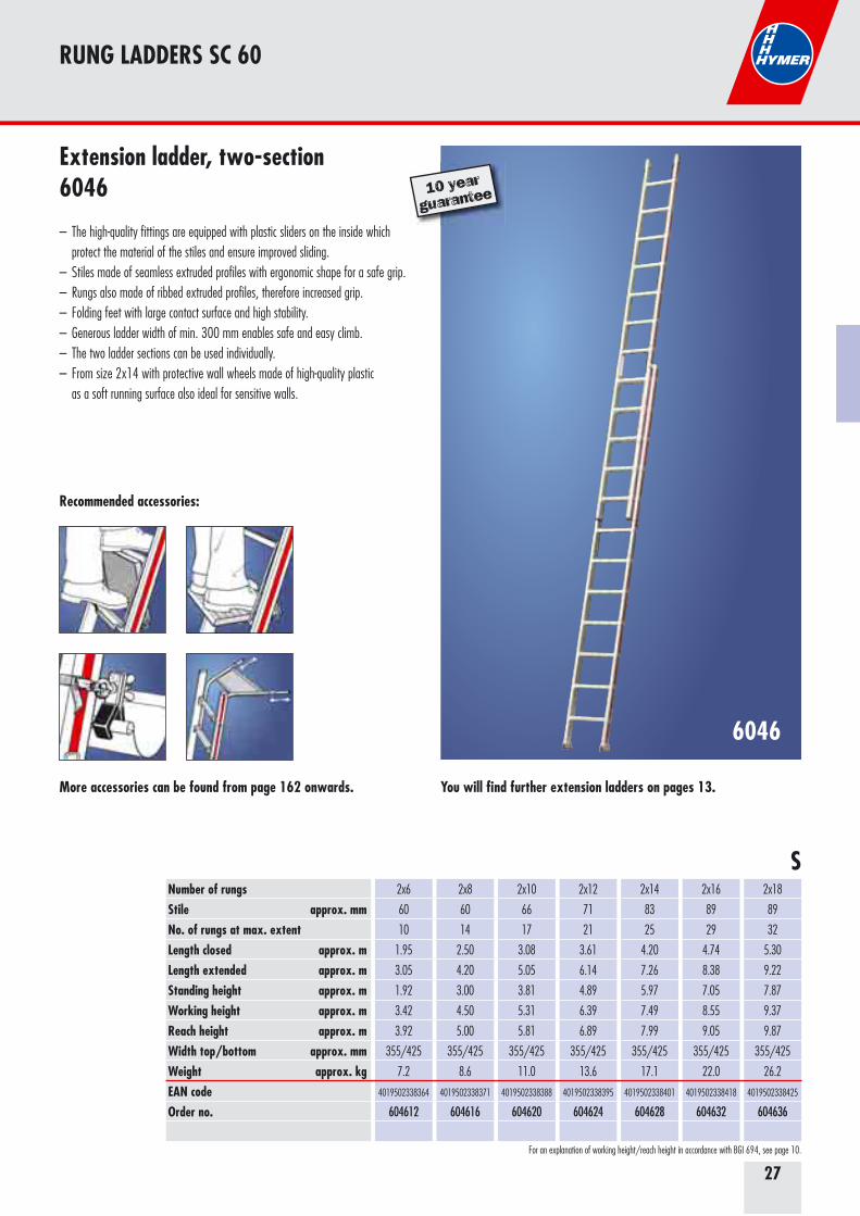
Extension ladder, two-section6046
– The high-quality fittings are equipped with plastic sliders on the inside which protect the material of the stiles and ensure improved sliding.– Stiles made of seamless extruded profiles with ergonomic shape for a safe grip.– Rungs also made of ribbed extruded profiles, therefore increased grip. – Folding feet with large contact surface and high stability.– Generous ladder width of min. 300 mm enables safe and easy climb. – The two ladder sections can be used individually. – From size 2x14 with protective wall wheels made of high-quality plastic as a soft running surface also ideal for sensitive walls.
10 year
guarantee
You will find further extension ladders on pages 13.
28
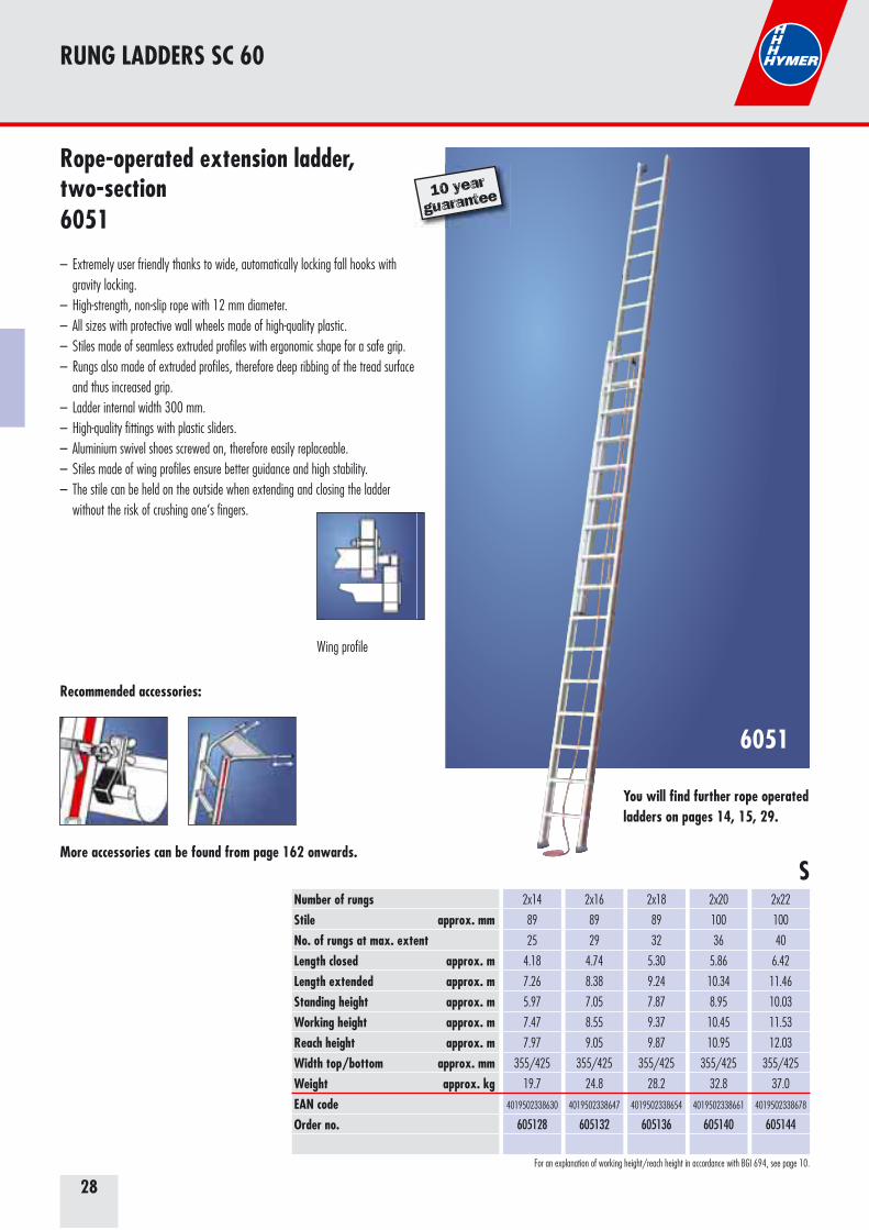
6051
Number of rungsStile approx. mm No. of rungs at max. extentLength closed approx. mLength extended approx. mStanding height approx. mWorking height approx. mReach height approx. mWidth top/bottom approx. mmWeight approx. kgEAN codeOrder no.
2x14
89
25
4.18
7.26
5.97
7.47
7.97
355/425
19.7
4019502338630
605128
2x16
89
29
4.74
8.38
7.05
8.55
9.05
355/425
24.8
4019502338647
605132
2x18
89
32
5.30
9.24
7.87
9.37
9.87
355/425
28.2
4019502338654
605136
2x20
100
36
5.86
10.34
8.95
10.45
10.95
355/425
32.8
4019502338661
605140
2x22
100
40
6.42
11.46
10.03
11.53
12.03
355/425
37.0
4019502338678
605144
Recommended accessories:
RUNG LADDERS SC 60
SMore accessories can be found from page 162 onwards.
For an explanation of working height/reach height in accordance with BGI 694, see page 10.
Rope-operated extension ladder, two-section6051
– Extremely user friendly thanks to wide, automatically locking fall hooks with gravity locking. – High-strength, non-slip rope with 12 mm diameter. – All sizes with protective wall wheels made of high-quality plastic. – Stiles made of seamless extruded profiles with ergonomic shape for a safe grip. – Rungs also made of extruded profiles, therefore deep ribbing of the tread surface and thus increased grip. – Ladder internal width 300 mm.– High-quality fittings with plastic sliders.– Aluminium swivel shoes screwed on, therefore easily replaceable.– Stiles made of wing profiles ensure better guidance and high stability.– The stile can be held on the outside when extending and closing the ladder without the risk of crushing one‘s fingers.
Wing profile
10 year
guarantee
You will find further rope operated ladders on pages 14, 15, 29.
29
RUNG LADDERS SC 60
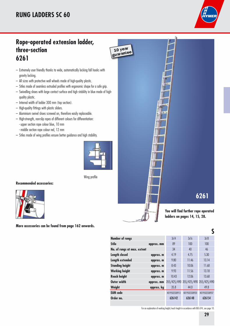
6261
SNumber of rungsStile approx. mm No. of rungs at max. extentLength closed approx. mLength extended approx. mStanding height approx. mWorking height approx. mReach height approx. mOuter width approx. mmWeight approx. kgEAN codeOrder no.
3x14
89
34
4.19
9.80
8.43
9.93
10.43
355/425/490
35.8
4019502338913
626142
3x16
100
40
4.75
11.46
10.06
11.56
12.06
355/425/490
44.0
4019502338920
626148
3x18
100
46
5.30
13.14
11.68
13.18
13.68
355/425/490
49.8
4019502338937
626154
Recommended accessories:
More accessories can be found from page 162 onwards.
For an explanation of working height/reach height in accordance with BGI 694, see page 10.
Rope-operated extension ladder, three-section6261
– Extremely user friendly thanks to wide, automatically locking fall hooks with gravity locking. – All sizes with protective wall wheels made of high-quality plastic.– Stiles made of seamless extruded profiles with ergonomic shape for a safe grip. – Swivelling shoes with large contact surface and high stability in blue made of high- quality plastic. – Internal width of ladder 300 mm (top section).– High-quality fittings with plastic sliders.– Aluminium swivel shoes screwed on, therefore easily replaceable.– High-strength, non-slip ropes of different colours for differentiation: - upper section rope colour blue, 10 mm - middle section rope colour red, 12 mm– Stiles made of wing profiles ensure better guidance and high stability.
Wing profile
10 year
guarantee
You will find further rope operated ladders on pages 14, 15, 28.
30
STEP LADDERS SC 60
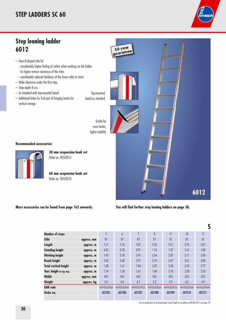
6012
Number of stepsStile approx. mm Length approx. mStanding height approx. mWorking height approx. mReach height approx. mTotal vertical height approx. mVert. height to top step approx. mWidth approx. mmWeight approx. kgEAN codeOrder no.
5
81
1.51
0.45
1.95
2.45
1.38
1.14
425
3.4
4019502339538
601205
6
81
1.76
0.78
2.18
2.68
1.61
1.38
425
4.0
4019502339545
601206
7
81
2.01
0.91
2.41
2.91
1.84
1.61
425
4.7
4019502339552
601207
8
81
2.26
1.14
2.64
3.14
2.07
1.84
425
5.2
4019502339569
601208
9
81
2.51
1.37
2.87
3.37
2.30
2.10
425
5.9
4019502339576
601209
10
81
2.76
1.61
3.11
3.61
2.53
2.30
425
6.3
4019502339583
601210
11
81
3.01
1.84
3.34
3.84
2.77
2.53
425
6.9
4019502339590
601211
S
More accessories can be found from page 162 onwards.
Step leaning ladder6012
– New D-shaped stile for - considerably higher feeling of safety when working on the ladder - 4x higher torsion resistance of the stiles - considerably reduced tendency of the lower stiles to twist– Wide clearance under the first step.– Step depth 8 cm. – As standard with top-mounted board. – Additional holes for 2nd pair of hanging hooks for vertical storage.
D-stile for even better,
higher stability
Recommended accessories:
30 mm suspension hook setOrder no. 0050052
60 mm suspension hook setOrder no. 0050053
You will find further step leaning ladders on page 38.
10 year
guarantee
Top-mounted board as standard
For an explanation of working height/reach height in accordance with BGI 694, see page 10.
31
RUNG LADDERS SC 60
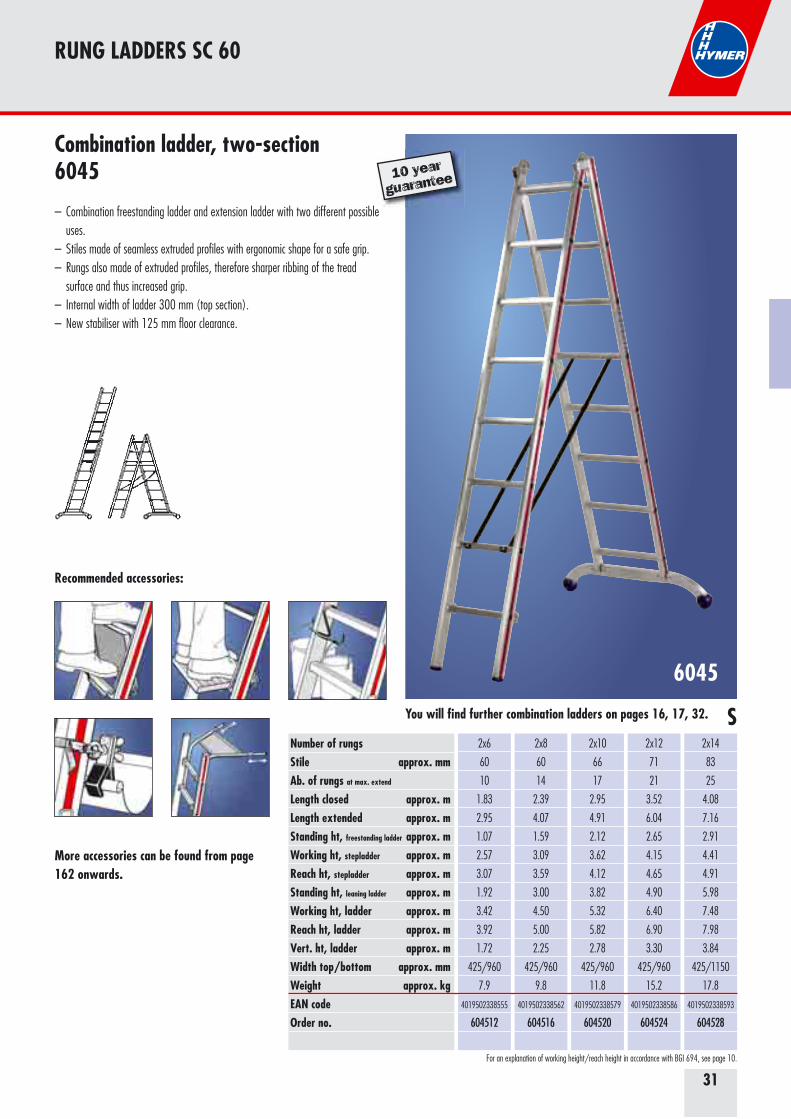
6045
Number of rungsStile approx. mm Ab. of rungs at max. extend
Length closed approx. mLength extended approx. mStanding ht, freestanding ladder approx. mWorking ht, stepladder approx. mReach ht, stepladder approx. mStanding ht, leaning ladder approx. mWorking ht, ladder approx. mReach ht, ladder approx. mVert. ht, ladder approx. mWidth top/bottom approx. mmWeight approx. kgEAN codeOrder no.
2x6
60
10
1.83
2.95
1.07
2.57
3.07
1.92
3.42
3.92
1.72
425/960
7.9
4019502338555
604512
2x8
60
14
2.39
4.07
1.59
3.09
3.59
3.00
4.50
5.00
2.25
425/960
9.8
4019502338562
604516
2x10
66
17
2.95
4.91
2.12
3.62
4.12
3.82
5.32
5.82
2.78
425/960
11.8
4019502338579
604520
2x12
71
21
3.52
6.04
2.65
4.15
4.65
4.90
6.40
6.90
3.30
425/960
15.2
4019502338586
604524
2x14
83
25
4.08
7.16
2.91
4.41
4.91
5.98
7.48
7.98
3.84
425/1150
17.8
4019502338593
604528
Recommended accessories:
S
More accessories can be found from page 162 onwards.
For an explanation of working height/reach height in accordance with BGI 694, see page 10.
Combination ladder, two-section6045
– Combination freestanding ladder and extension ladder with two different possible uses. – Stiles made of seamless extruded profiles with ergonomic shape for a safe grip. – Rungs also made of extruded profiles, therefore sharper ribbing of the tread surface and thus increased grip. – Internal width of ladder 300 mm (top section).– New stabiliser with 125 mm floor clearance.
10 year
guarantee
You will find further combination ladders on pages 16, 17, 32.
32
6047
RUNG LADDERS SC 60
Number of rungsStile approx. mm Ab. of rungs at max. extend
Length closed approx. mLength extended approx. mStanding ht, freestanding ladder approx. mWorking ht, stepladder approx. mReach ht, stepladder approx. mStanding ht, leaning ladder approx. mWorking ht, ladder approx. mReach ht, ladder approx. mVert. ht, ladder approx. mWidth top/bottom approx. mmWeight approx. kgEAN codeOrder no.
3x6
60
14
1.95
4.19
1.60
3.10
3.60
3.00
4.50
5.00
2.89
495/1030
12.4
4019502338487
604718
3x7
66
16
2.22
4.75
2.13
3.63
4.13
3.54
5.04
5.54
3.42
495/1030
14.2
4019502338494
604721
3x8
71
19
2.50
5.59
2.65
4.15
4.65
4.35
5.85
6.35
3.95
495/1030
17.0
4019502338500
604724
3x9
83
21
2.79
6.15
2.92
4.12
4.92
4.89
6.39
6.89
4.20
495/1150
20.6
4019502338517
604727
3x10
83
24
3.06
6.98
3.44
4.94
5.44
5.70
7.20
7.70
4.73
495/1150
22.4
4019502338524
604730
3x12
89
29
3.62
8.38
4.49
5.99
6.49
7.06
8.56
9.06
5.78
495/1150
29.1
4019502338531
604736
3x14
89
34
4.18
9.78
5.28
6.78
7.28
8.41
9.91
10.41
6.57
495/1150
34.6
4019502338548
604742
SMore accessories can be found from page 162 onwards.
For an explanation of working height/reach height in accordance with BGI 694, see page 10.
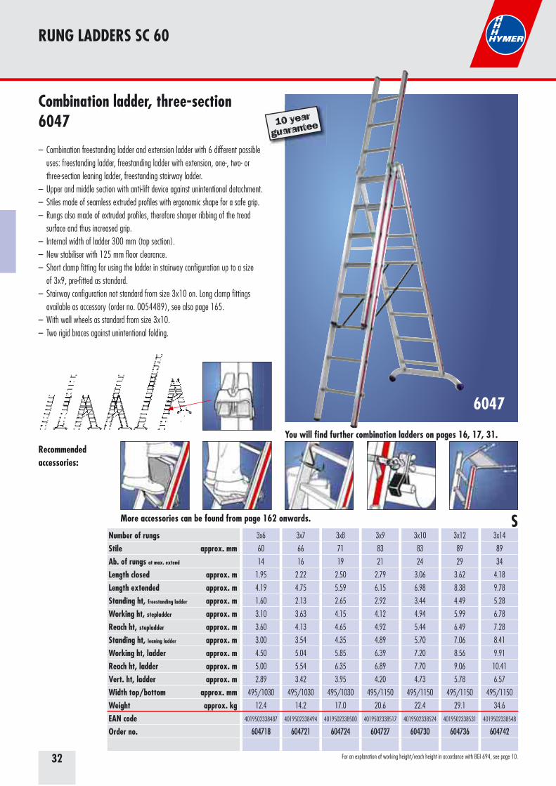
Combination ladder, three-section6047
– Combination freestanding ladder and extension ladder with 6 different possible uses: freestanding ladder, freestanding ladder with extension, one-, two- or three-section leaning ladder, freestanding stairway ladder.– Upper and middle section with anti-lift device against unintentional detachment. – Stiles made of seamless extruded profiles with ergonomic shape for a safe grip. – Rungs also made of extruded profiles, therefore sharper ribbing of the tread surface and thus increased grip. – Internal width of ladder 300 mm (top section).– New stabiliser with 125 mm floor clearance.– Short clamp fitting for using the ladder in stairway configuration up to a size of 3x9, pre-fitted as standard.– Stairway configuration not standard from size 3x10 on. Long clamp fittings
available as accessory (order no. 0054489), see also page 165.– With wall wheels as standard from size 3x10.– Two rigid braces against unintentional folding.
Recommended accessories:
10 year
guarantee
You will find further combination ladders on pages 16, 17, 31.
33
RUNG LADDERS SC 60
6023
Recommended accessories:
More accessories can be found from page 162 onwards. S
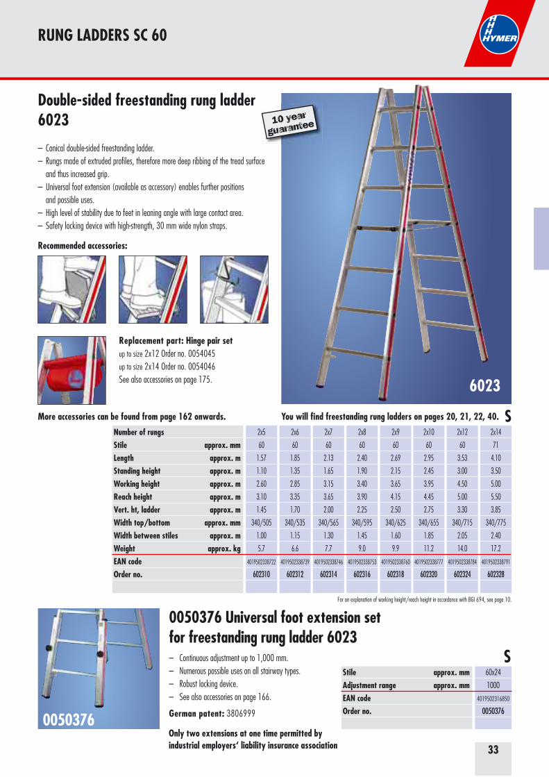
Double-sided freestanding rung ladder6023
– Conical double-sided freestanding ladder. – Rungs made of extruded profiles, therefore more deep ribbing of the tread surface and thus increased grip. – Universal foot extension (available as accessory) enables further positions and possible uses. – High level of stability due to feet in leaning angle with large contact area. – Safety locking device with high-strength, 30 mm wide nylon straps.
Replacement part: Hinge pair setup to size 2x12 Order no. 0054045up to size 2x14 Order no. 0054046See also accessories on page 175.
Number of rungsStile approx. mm Length approx. mStanding height approx. mWorking height approx. mReach height approx. mVert. ht, ladder approx. mWidth top/bottom approx. mmWidth between stiles approx. mWeight approx. kgEAN codeOrder no.
2x5
60
1.57
1.10
2.60
3.10
1.45
340/505
1.00
5.7
4019502338722
602310
2x6
60
1.85
1.35
2.85
3.35
1.70
340/535
1.15
6.6
4019502338739
602312
2x7
60
2.13
1.65
3.15
3.65
2.00
340/565
1.30
7.7
4019502338746
602314
2x8
60
2.40
1.90
3.40
3.90
2.25
340/595
1.45
9.0
4019502338753
602316
2x9
60
2.69
2.15
3.65
4.15
2.50
340/625
1.60
9.9
4019502338760
602318
2x10
60
2.95
2.45
3.95
4.45
2.75
340/655
1.85
11.2
4019502338777
602320
2x12
60
3.53
3.00
4.50
5.00
3.30
340/715
2.05
14.0
4019502338784
602324
2x14
71
4.10
3.50
5.00
5.50
3.85
340/775
2.40
17.2
4019502338791
602328
10 year
guarantee
For an explanation of working height/reach height in accordance with BGI 694, see page 10.
0050376 Universal foot extension setfor freestanding rung ladder 6023– Continuous adjustment up to 1,000 mm.– Numerous possible uses on all stairway types.– Robust locking device.– See also accessories on page 166.
German patent: 3806999 0050376
S
Only two extensions at one time permitted by industrial employers‘ liability insurance association
Stile approx. mmAdjustment range approx. mm EAN code Order no.
60x24
1000
4019502316850
0050376
You will find freestanding rung ladders on pages 20, 21, 22, 40.
34
STEP LADDERS SC 60
6026
Number of stepsStile approx. mm Length approx. mStanding heigt (height to platform) approx. mWorking height approx. mReach height approx. mTotal vertical height approx. mWidth approx. mmWidth between stiles approx. mWeight approx. kgEAN codeOrder no.
3
82
1.45
0.68
2.18
2.68
1.33
450
0.70
5.6
4019502339743
602603
4
82
1.70
0.91
2.41
2.91
1.56
475
0.85
6.3
4019502339750
602604
5
82
1.95
1.14
2.64
3.14
1.79
500
1.00
7.4
4019502339767
602605
6
82
2.22
1.37
2.87
3.37
2.02
525
1.15
8.2
4019502339774
602606
7
82
2.45
1.60
3.10
3.60
2.25
550
1.30
9.4
4019502339781
602607
8
82
2.70
1.84
3.34
3.84
2.49
575
1.50
10.5
4019502339798
602608
10
82
3.20
2.30
3.80
4.30
2.95
625
1.80
12.2
4019502339804
602610
S
For an explanation of working height/reach height in accordance with BGI 694, see page 10.
D-stile for even better, higher stability
Wide, slip resistant plastic feet
Tool tray
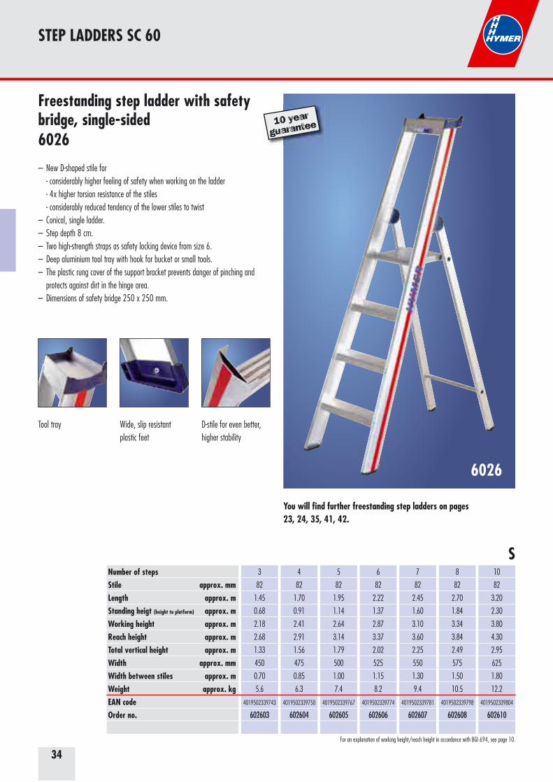
Freestanding step ladder with safety bridge, single-sided6026
– New D-shaped stile for - considerably higher feeling of safety when working on the ladder - 4x higher torsion resistance of the stiles - considerably reduced tendency of the lower stiles to twist– Conical, single ladder. – Step depth 8 cm. – Two high-strength straps as safety locking device from size 6.– Deep aluminium tool tray with hook for bucket or small tools. – The plastic rung cover of the support bracket prevents danger of pinching and protects against dirt in the hinge area. – Dimensions of safety bridge 250 x 250 mm.
10 year
guarantee
You will find further freestanding step ladders on pages 23, 24, 35, 41, 42.
35
STEP LADDERS SC 60
6024
Number of stepsStile approx. mm Length approx. mStanding height approx. mWorking height approx. mReach height approx. mTotal vertical height approx. mWidth approx. mmWidth between stiles approx. mWeight approx. kgEAN codeOrder no.
2x2
82
0.52
0.20
1.70
2.20
0.45
425
0.55
3.2
4019502339620
602404
2x3
82
0.78
0.45
1.95
2.45
0.65
450
0.75
4.5
4019502339637
602406
2x4
82
1.02
0.70
2.20
2.70
0.90
475
0.95
5.7
4019502339644
602408
2x5
82
1.26
0.90
2.40
2.90
1.15
500
1.15
6.9
4019502339651
602410
2x6
82
1.50
1.15
2.65
3.15
1.35
525
1.35
8.1
4019502339668
602412
2x7
82
1.77
1.40
2.90
3.40
1.60
550
1.55
9.5
4019502339675
602414
2x8
82
2.00
1.60
3.10
3.60
1.80
575
1.75
10.8
4019502339682
602416
2x10
82
2.50
2.10
3.60
4.10
2.30
625
2.10
13.7
4019502339699
602420
S
For an explanation of working height/reach height in accordance with BGI 694, see page 10.
D-stile for even better, higher stability
Wide, slip resistant plastic feet
Continuous hinges Transport position protects against trapped fingers
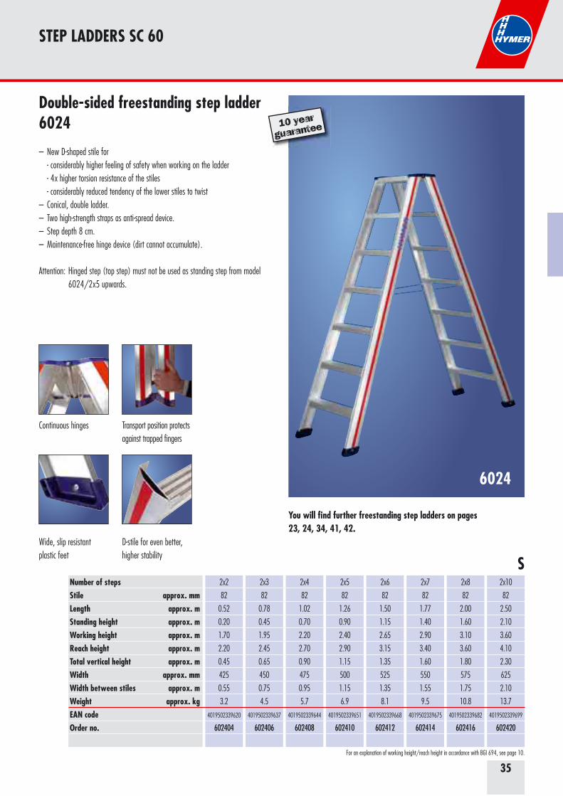
Double-sided freestanding step ladder6024
– New D-shaped stile for - considerably higher feeling of safety when working on the ladder - 4x higher torsion resistance of the stiles - considerably reduced tendency of the lower stiles to twist– Conical, double ladder.– Two high-strength straps as anti-spread device. – Step depth 8 cm.– Maintenance-free hinge device (dirt cannot accumulate).
Attention: Hinged step (top step) must not be used as standing step from model 6024/2x5 upwards.
10 year
guarantee
You will find further freestanding step ladders on pages 23, 24, 34, 41, 42.
36
FOR YOUR NOTES
37
Leaning ladders Step ladders: Leaning ladder 38
Freestanding ladders Rung ladders: Telescopic ladders, freestanding ladders 39 Step ladders: Single-sided and double-sided freestanding ladders 41
Safety and Comfort SC 80
Professional ladders and towers for industry and trade
38
STEP LADDERS SC 80
8012
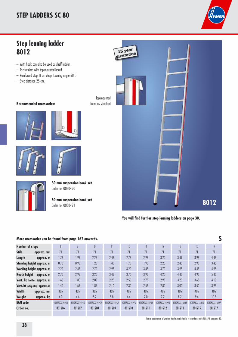
Number of stepsStile approx. mm Length approx. mStanding height approx. mWorking height approx. mReach height approx. mVert. ht, ladder approx. mVert. ht to top step approx. m
Width approx. mmWeight approx. kgEAN codeOrder no.
6
71
1.73
0.70
2.20
2.70
1.60
1.40
405
4.0
4019502315938
801206
7
71
1.95
0.95
2.45
2.95
1.80
1.65
405
4.6
4019502315945
801207
8
71
2.23
1.20
2.70
3.20
2.05
1.85
405
5.2
4019502315952
801208
9
71
2.48
1.45
2.95
3.45
2.25
2.10
405
5.8
4019502315969
801209
10
71
2.73
1.70
3.20
3.70
2.50
2.30
405
6.4
4019502315976
801210
11
71
2.97
1.95
3.45
3.95
2.75
2.55
405
7.0
4019502315983
801211
12
71
3.20
2.20
3.70
4.20
2.95
2.80
405
7.7
4019502315990
801212
13
71
3.49
2.45
3.95
4.45
3.20
3.00
405
8.2
4019502316003
801213
15
71
3.98
2.95
4.45
4.95
3.65
3.50
405
9.4
4019502316010
801215
17
71
4.48
3.45
4.95
5.45
4.10
3.95
405
10.5
4019502316027
801217
Recommended accessories:
S
15 year
guarantee
For an explanation of working height/reach height in accordance with BGI 694, see page 10.
Step leaning ladder8012
– With hook can also be used as shelf ladder. – As standard with top-mounted board.– Reinforced step, 8 cm deep. Leaning angle 68°. – Step distance 25 cm.
You will find further step leaning ladders on page 30.
More accessories can be found from page 162 onwards.
Top-mounted board as standard
30 mm suspension hook setOrder no. 0050420
60 mm suspension hook setOrder no. 0050421
39
RUNG LADDERS SC 80
8042
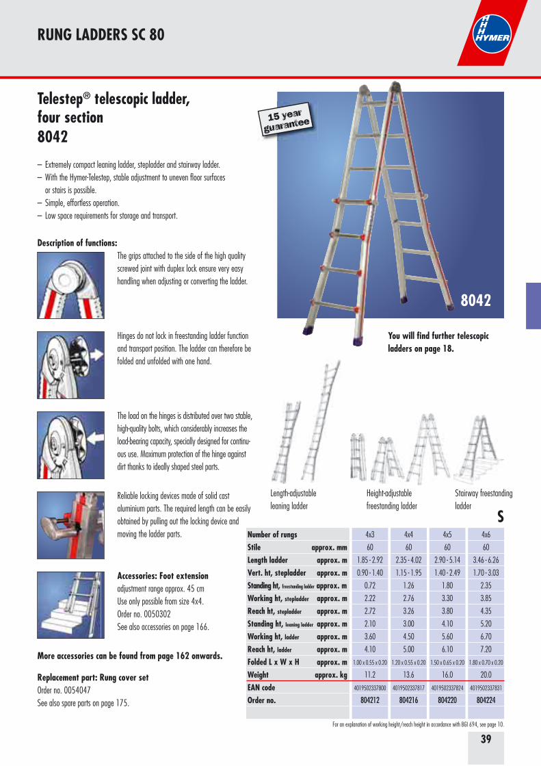
Number of rungsStile approx. mm Length ladder approx. mVert. ht, stepladder approx. mStanding ht, freestanding ladder approx. mWorking ht, stepladder approx. mReach ht, stepladder approx. mStanding ht, leaning ladder approx. mWorking ht, ladder approx. mReach ht, ladder approx. mFolded L x W x H approx. mWeight approx. kgEAN codeOrder no.
4x3
60
1.85 - 2.92
0.90 - 1.40
0.72
2.22
2.72
2.10
3.60
4.10
1.00 x 0.55 x 0.20
11.2
4019502337800
804212
4x4
60
2.35 - 4.02
1.15 - 1.95
1.26
2.76
3.26
3.00
4.50
5.00
1.20 x 0.55 x 0.20
13.6
4019502337817
804216
4x5
60
2.90 - 5.14
1.40 - 2.49
1.80
3.30
3.80
4.10
5.60
6.10
1.50 x 0.65 x 0.20
16.0
4019502337824
804220
4x6
60
3.46 - 6.26
1.70 - 3.03
2.35
3.85
4.35
5.20
6.70
7.20
1.80 x 0.70 x 0.20
20.0
4019502337831
804224
S
The grips attached to the side of the high quality screwed joint with duplex lock ensure very easy handling when adjusting or converting the ladder.
Hinges do not lock in freestanding ladder function and transport position. The ladder can therefore be folded and unfolded with one hand.
The load on the hinges is distributed over two stable, high-quality bolts, which considerably increases the load-bearing capacity, specially designed for continu-ous use. Maximum protection of the hinge against dirt thanks to ideally shaped steel parts.
Reliable locking devices made of solid cast aluminium parts. The required length can be easily obtained by pulling out the locking device and moving the ladder parts.
Replacement part: Rung cover setOrder no. 0054047See also spare parts on page 175.
Description of functions:
15 year
guarantee
For an explanation of working height/reach height in accordance with BGI 694, see page 10.
Telestep® telescopic ladder,four section8042
– Extremely compact leaning ladder, stepladder and stairway ladder. – With the Hymer-Telestep, stable adjustment to uneven floor surfaces or stairs is possible.– Simple, effortless operation.– Low space requirements for storage and transport.
You will find further telescopic ladders on page 18.
More accessories can be found from page 162 onwards.
Height-adjustable freestanding ladder
Stairway freestanding ladder
Length-adjustable leaning ladder
Accessories: Foot extensionadjustment range approx. 45 cmUse only possible from size 4x4.Order no. 0050302See also accessories on page 166.
40
RUNG LADDERS SC 80
7-1490
Number of rungsLength approx. mStanding height approx. mWorking height approx. mReach height approx. mVert. ht, stepladder approx. mWidth between stiles approx. mWeight approx. kgEAN codeOrder no.
2x4
1.24
0.80
2.30
2.80
1.18
490
7.0
4019502340862
7149008
2x5
1.52
1.10
2.60
3.10
1.45
520
9.0
4019502340879
7149010
2x6
1.80
1.35
2.85
3.35
1.70
550
11.0
4019502340886
7149012
2x7
2.08
1.65
3.15
3.65
2.00
580
13.0
4019502340893
7149014
2x8
2.36
1.90
3.40
3.90
2.25
610
15.0
4019502340909
7149016
2x10
2.92
2.45
3.95
4.45
2.75
670
19.0
4019502340916
7149020
2x12
3.48
3.00
4.50
5.00
3.30
730
23.0
4019502340923
7149024
S
For an explanation of working height/reach height in accordance with BGI 694, see page 10.
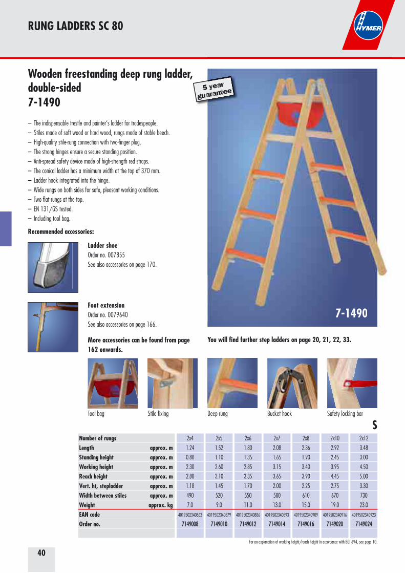
Wooden freestanding deep rung ladder, double-sided7-1490
– The indispensable trestle and painter‘s ladder for tradespeople. – Stiles made of soft wood or hard wood, rungs made of stable beech. – High-quality stile-rung connection with two-finger plug. – The strong hinges ensure a secure standing position. – Anti-spread safety device made of high-strength red straps. – The conical ladder has a minimum width at the top of 370 mm. – Ladder hook integrated into the hinge.– Wide rungs on both sides for safe, pleasant working conditions.– Two flat rungs at the top.– EN 131/GS tested.– Including tool bag.
, 5 year
guarantee
Bucket hook Safety locking barTool bag Stile fixing
7-1490
year
arantee
You will find further step ladders on page 20, 21, 22, 33.
Deep rung
More accessories can be found from page 162 onwards.
Recommended accessories:
Ladder shoeOrder no. 007855See also accessories on page 170.
Foot extensionOrder no. 0079640See also accessories on page 166.
41
STEP LADDERS SC 80
8026
Number of stepsStile approx. mm Length approx. mStanding height approx. mWorking height approx. mReach height approx. mTotal vert. height approx. mWidth approx. mmWidth between stiles approx. mWeight approx. kgEAN codeOrder no.
4
71
1.70
0.93
2.43
2.93
1.55
480
0.90
5.8
4019502316119
802604
5
71
1.95
1.16
2.66
3.16
1.78
500
1.05
6.7
4019502316126
802605
6
71
2.20
1.40
2.90
3.40
2.01
530
1.20
7.6
4019502316133
802606
7
71
2.45
1.63
3.13
3.63
2.25
550
1.35
8.6
4019502342316
802607
8
71
2.70
1.85
3.35
3.85
2.48
570
1.50
9.6
4019502316140
802608
10
71
3.20
2.32
3.82
4.32
2.94
630
1.85
12.0
4019502316157
802610
12
71
3.70
2.78
4.28
4.78
3.40
680
2.20
14.5
4019502316164
802612
14
71
4.20
3.25
4.75
5.25
3.87
740
2.55
17.0
4019502340107
802614
S
Number of stepsEAN codeOrder no.
4 + 5
4019502327177
0050431
6 + 7
4019502327184
0050432
8 + 10
4019502327191
0050433
12 + 14
4019502327221
0050437
Spring-loaded castor type
EAN codeOrder no.
fixed
on the stile
4019502327207
0050434
swivelling
on the stile
4019502327214
0050435
fixed
on support part
4019502327047
0050356
swivelling on
support part
4019502327054
0050357
Additional price for set of spring-loaded castors, self-locking, fitted by Hymer
Additional price for set of braces, rigid, removable, fitted by Hymer
Spring-loaded castors and braces as accessories and further accessories may be found from page 162 onwards.
For an explanation of working height/reach height in accordance with BGI 694, see page 10.
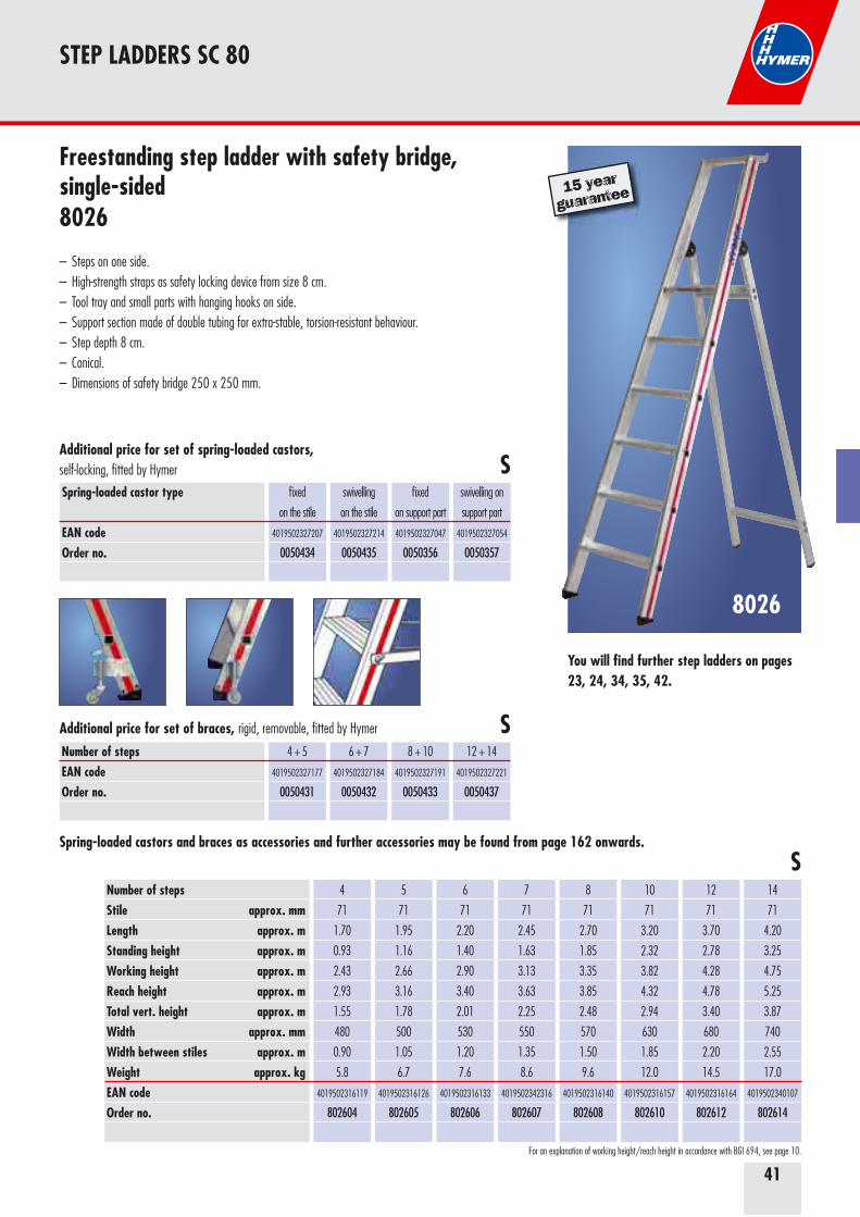
Freestanding step ladder with safety bridge, single-sided8026
– Steps on one side. – High-strength straps as safety locking device from size 8 cm.– Tool tray and small parts with hanging hooks on side. – Support section made of double tubing for extra-stable, torsion-resistant behaviour. – Step depth 8 cm.– Conical.– Dimensions of safety bridge 250 x 250 mm.
S
S
15 year
guarantee
You will find further step ladders on pages 23, 24, 34, 35, 42.
42
STEP LADDERS SC 80
8024
S
SNumber of stepsEAN codeOrder no.
2x2
4019502327290
0050646
2x3
4019502327252
0050575
2x4+2x5
4019502327146
0050428
2x6+2x7
4019502327269
0050576
2x8+2x9+2x10
4019502327153
0050429
2x12
4019502327160
0050430
Spring-loaded castor type
EAN codeOrder no.
fixed
on the stile
4019502327207
0050434
swivelling
on the stile
4019502327214
0050435
Additional price for set of spring-loaded castors, self-locking, fitted by Hymer
Spring-loaded castors and braces as accessories and further accessories may be found from page 162 onwards.
For an explanation of working height/reach height in accordance with BGI 694, see page 10.
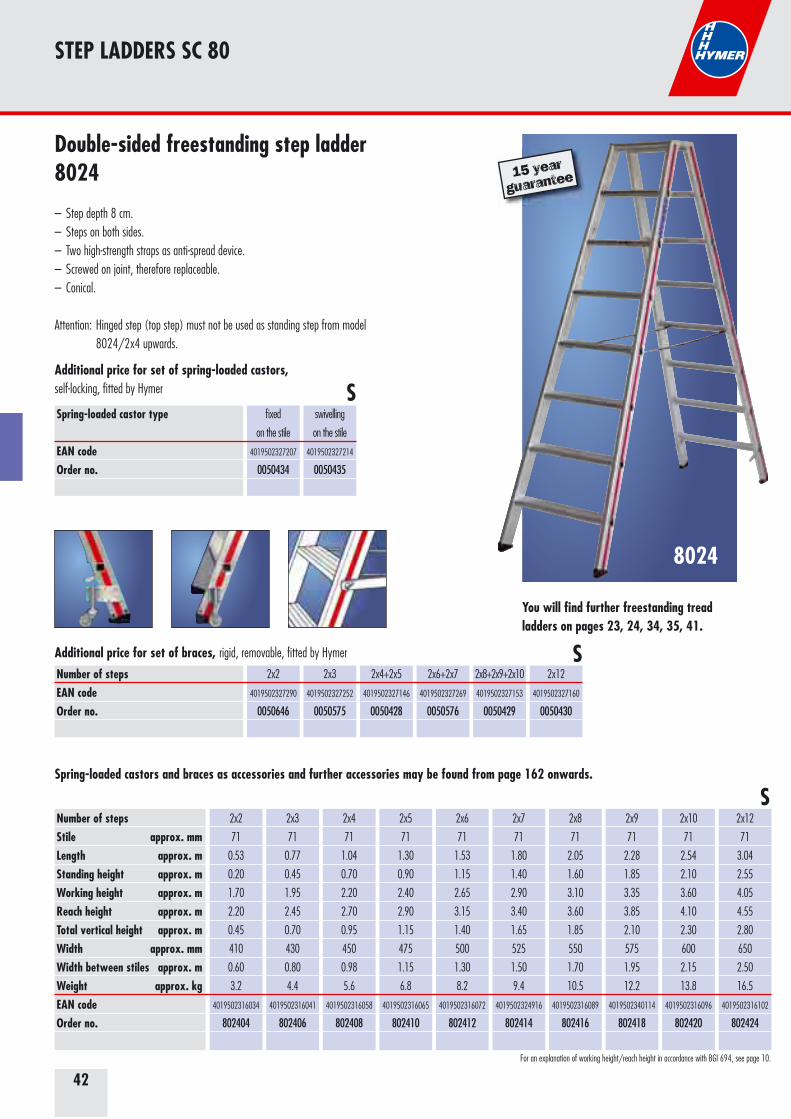
Double-sided freestanding step ladder8024
– Step depth 8 cm. – Steps on both sides.– Two high-strength straps as anti-spread device. – Screwed on joint, therefore replaceable. – Conical.
Attention: Hinged step (top step) must not be used as standing step from model 8024/2x4 upwards.
SNumber of stepsStile approx. mm Length approx. mStanding height approx. mWorking height approx. mReach height approx. mTotal vertical height approx. mWidth approx. mmWidth between stiles approx. mWeight approx. kgEAN codeOrder no.
2x2
71
0.53
0.20
1.70
2.20
0.45
410
0.60
3.2
4019502316034
802404
2x3
71
0.77
0.45
1.95
2.45
0.70
430
0.80
4.4
4019502316041
802406
2x4
71
1.04
0.70
2.20
2.70
0.95
450
0.98
5.6
4019502316058
802408
2x5
71
1.30
0.90
2.40
2.90
1.15
475
1.15
6.8
4019502316065
802410
2x6
71
1.53
1.15
2.65
3.15
1.40
500
1.30
8.2
4019502316072
802412
2x7
71
1.80
1.40
2.90
3.40
1.65
525
1.50
9.4
4019502324916
802414
2x8
71
2.05
1.60
3.10
3.60
1.85
550
1.70
10.5
4019502316089
802416
2x9
71
2.28
1.85
3.35
3.85
2.10
575
1.95
12.2
4019502340114
802418
2x10
71
2.54
2.10
3.60
4.10
2.30
600
2.15
13.8
4019502316096
802420
2x12
71
3.04
2.55
4.05
4.55
2.80
650
2.50
16.5
4019502316102
802424
15 year
guarantee
You will find further freestanding tread ladders on pages 23, 24, 34, 35, 41.
Additional price for set of braces, rigid, removable, fitted by Hymer
43
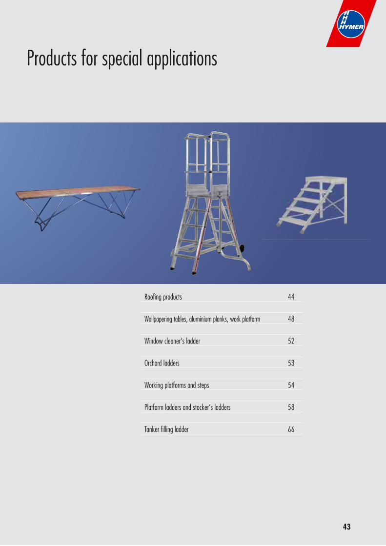
Roofing products 44
Wallpapering tables, aluminium planks, work platform 48
Window cleaner‘s ladder 52
Orchard ladders 53
Working platforms and steps 54
Platform ladders and stocker‘s ladders 58
Tanker filling ladder 66
Products for special applications
44
ROOFING PRODUCTS
Number of rungsLength approx. mWidth approx. mmWeight approx. kgEAN codeOrder no.
7
1.95
350
3.5
4019502307537
409507
10
2.80
350
4.9
4019502307544
409510
14
3.90
350
6.8
4019502307551
409514
7
1.95
350
3.5
4019502335202
409707
10
2.80
350
4.9
4019502335219
409710
14
3.90
350
6.8
4019502335226
409714
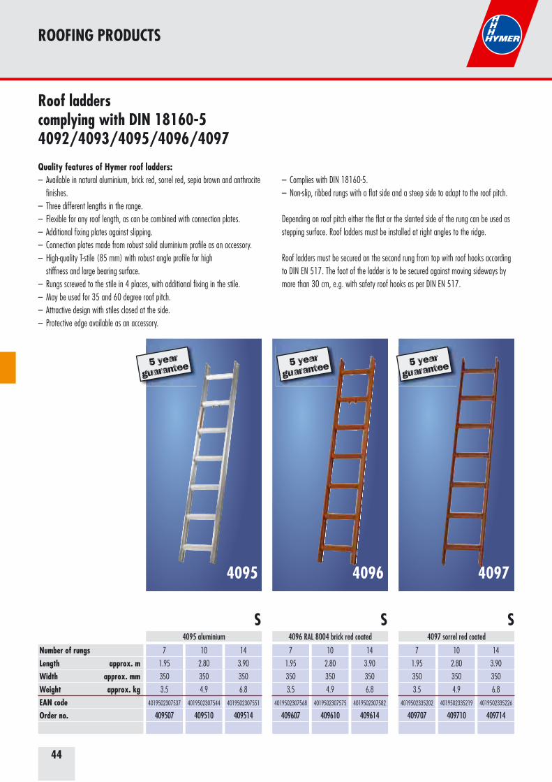
4095 aluminium 4097 sorrel red coated
7
1.95
350
3.5
4019502307568
409607
10
2.80
350
4.9
4019502307575
409610
14
3.90
350
6.8
4019502307582
409614
4096 RAL 8004 brick red coated
5 year
guarantee
4095 40974096
Roof ladders complying with DIN 18160-54092/4093/4095/4096/4097
Quality features of Hymer roof ladders:– Available in natural aluminium, brick red, sorrel red, sepia brown and anthracite finishes.– Three different lengths in the range.– Flexible for any roof length, as can be combined with connection plates.– Additional fixing plates against slipping. – Connection plates made from robust solid aluminium profile as an accessory.– High-quality T-stile (85 mm) with robust angle profile for high stiffness and large bearing surface.– Rungs screwed to the stile in 4 places, with additional fixing in the stile.– May be used for 35 and 60 degree roof pitch.– Attractive design with stiles closed at the side.– Protective edge available as an accessory.
– Complies with DIN 18160-5.– Non-slip, ribbed rungs with a flat side and a steep side to adapt to the roof pitch.
Depending on roof pitch either the flat or the slanted side of the rung can be used as stepping surface. Roof ladders must be installed at right angles to the ridge.
Roof ladders must be secured on the second rung from top with roof hooks according to DIN EN 517. The foot of the ladder is to be secured against moving sideways by more than 30 cm, e.g. with safety roof hooks as per DIN EN 517.
5 year
guarantee 5 year
guarantee
SSS
45
ROOFING PRODUCTS
7
1.95
350
3.5
4019502307476
409307
10
2.80
350
4.9
4019502307483
409310
14
3.90
350
6.8
4019502307490
409314
7
1.95
350
3.5
4019502313545
409207
10
2.80
350
4.9
4019502313552
409210
14
3.90
350
6.8
4019502313569
409214
4093 RAL 8014 dark brown coated4092 RAL 7016 anthracite coated
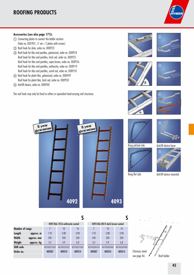
Accessories (see also page 171):� Connecting plates to connect the ladder sections Order no. 005907, (1 set = 2 plates with screws) � Roof hook for slate, order no. 008923 � Roof hook for tiles and pantiles, galvanized, order no. 008924 Roof hook for tiles and pantiles, brick red, order no. 008925 Roof hook for tiles and pantiles, sepia brown, order no. 008926 Roof hook for tiles and pantiles, anthracite, order no. 008919 Roof hook for tiles and pantiles, sorrel red, order no. 008918 � Roof hook for plaint tiles, galvanized, order no. 008949 Roof hook for plaint tiles, brick red, order no. 008950 � Anti-lift device, order no. 008940
The roof hook may only be fixed to rafters or equivalent load-carrying roof structures.
Roof ladderChimney stand see page 46
SS
Number of rungsLength approx. mWidth approx. mmWeight approx. kgEAN codeOrder no.
40934092
�
�
Anti-lift device loose
�
Anti-lift device mounted
�
Rung pitched side
Rung flat side
5 year
guarantee 5 year
guarantee
�
�
46
ROOFING PRODUCTS
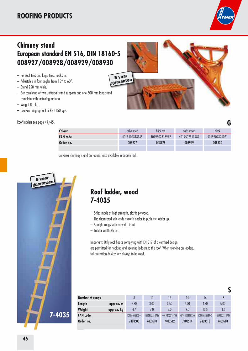
Chimney stand European standard EN 516, DIN 18160-5008927/008928/008929/008930
– For roof tiles and large tiles, hooks in.– Adjustable in four angles from 15° to 60°. – Stand 250 mm wide.– Set consisting of two universal stand supports and one 800 mm long stand complete with fastening material. – Weight 8.0 kg.– Load-carrying up to 1.5 kN (150 kg).
Roof ladders see page 44/45.
ColourEAN codeOrder no.
galvanised
4019502313965
008927
brick red
4019502313972
008928
dark brown
4019502313989
008929
black
4019502326071
008930
7-4035
Roof ladder, wood7-4035
– Stiles made of high-strength, elastic plywood. – The chamfered stile ends make it easier to push the ladder up. – Straight rungs with curved cut-out. – Ladder width 35 cm.
Important: Only roof hooks complying with EN 517 of a certified design are permitted for hooking and securing ladders to the roof. When working on ladders, fall-protection devices are always to be used.
Number of rungsLength approx. mWeight approx. kgEAN codeOrder no.
8
2.30
4.7
4019502330344
7403508
10
3.00
7.0
4019502315716
7403510
12
3.50
8.0
4019502315723
7403512
14
4.00
9.0
4019502315730
7403514
16
4.50
10.5
4019502315747
7403516
18
5.00
11.5
4019502315754
7403518
G
5 year
guarantee
S
5 year
guarantee
7-4035
NumLengWeigEAN Orde
5 year
guarantee
Universal chimney stand on request also available in auburn red.
47
FOR YOUR NOTES
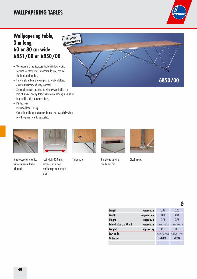
48
WALLPAPERING TABLES
6850/00
Wallpapering table, 3 m long, 60 or 80 cm wide6851/00 or 6850/00
– Wallpaper and multipurpose table with two folding sections for many uses in hobbies, leisure, around the home and garden. – Easy to store thanks to compact size when folded, easy to transport and easy to install.– Stable aluminium table frame with plywood table top.– Robust tubular folding frame with secure locking mechanism.– Large table, folds in two sections.– Printed ruler. – Permitted load 100 kg.– Clean the table-top thoroughly before use, especially when sensitive papers are to be pasted.
Length approx. mWidth approx. mmHeight approx. mFolded size L x W x H approx. mWeight approx. kgEAN codeOrder no.
3.05
800
0.78
1.05 x 0.80 x 0.10
18.0
4019502314443
685000
3.05
600
0.78
1.05 x 0.60 x 0.10
15.0
4019502314450
685100
Stable wooden table top with aluminium frame all round
Feet width 430 mm, seamless extruded profile, caps on the tube ends
Printed rule The strong carrying handle lies flat
Steel hinges
G
5 year
guarantee
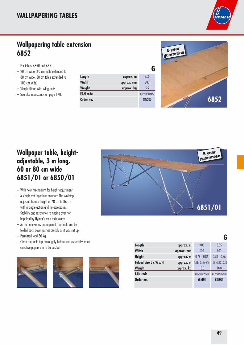
49
WALLPAPERING TABLES
6852
Wallpapering table extension6852
– For tables 6850 and 6851.– 20 cm wide (60 cm table extended to 80 cm wide, 80 cm table extended to 100 cm wide).– Simple fitting with wing bolts.– See also accessories on page 170.
Length approx. mWidth approx. mmWeight approx. kgEAN codeOrder no.
3.05
200
5.5
4019502314467
685200
6851/01
Wallpaper table, height-adjustable, 3 m long, 60 or 80 cm wide6851/01 or 6850/01
– With new mechanism for height adjustment.– A simple yet ingenious solution: The worktop, adjusted from a height of 78 cm to 86 cm with a single action and no accessories. – Stability and resistance to tipping over not impaired by Hymer‘s own technology. – As no accessories are required, the table can be folded back down just as quickly as it was set up. – Permitted load 80 kg.– Clean the table-top thoroughly before use, especially when sensitive papers are to be pasted.
3.05
800
0.78 + 0.86
1.05 x 0.80 x 0.10
18.0
4019502329638
685001
Length approx. mWidth approx. mmHeight approx. mFolded size L x W x H approx. mWeight approx. kgEAN codeOrder no.
3.05
600
0.78 + 0.86
1.05 x 0.60 x 0.10
15.0
4019502329621
685101
G
G
5 year
guarantee
5 year
guarantee
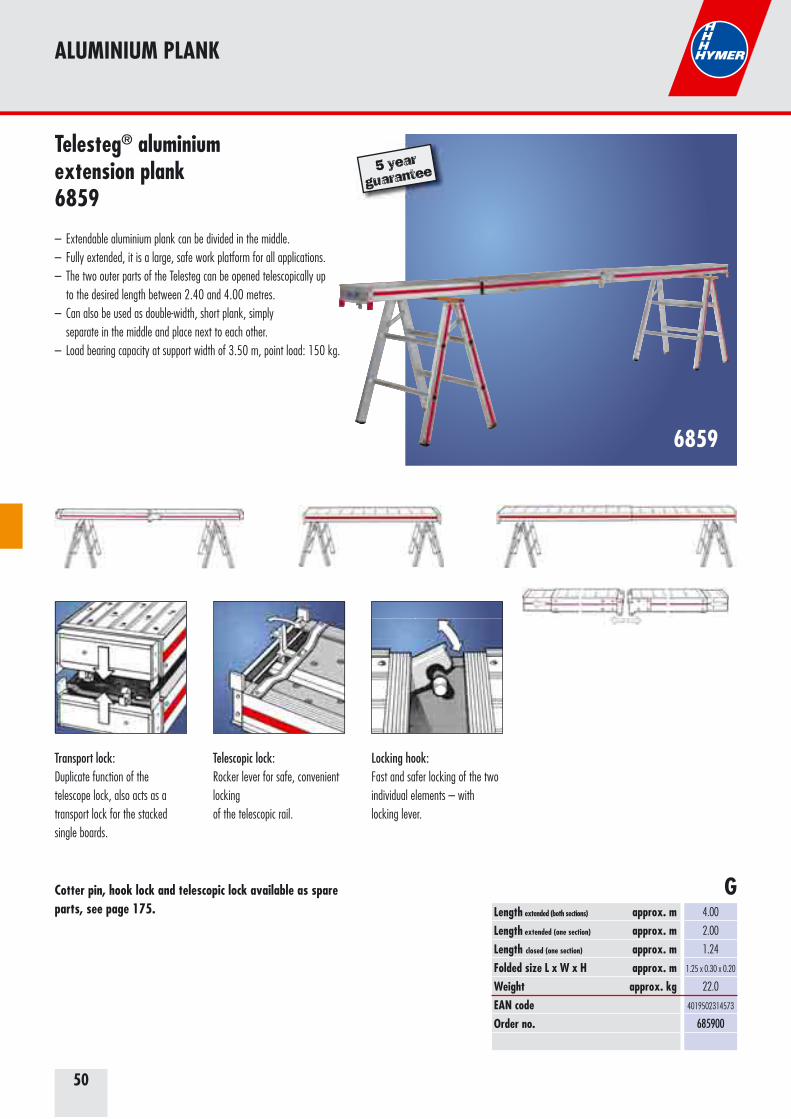
50
ALUMINIUM PLANK
Telesteg® aluminium extension plank6859
– Extendable aluminium plank can be divided in the middle.– Fully extended, it is a large, safe work platform for all applications.– The two outer parts of the Telesteg can be opened telescopically up to the desired length between 2.40 and 4.00 metres.– Can also be used as double-width, short plank, simply separate in the middle and place next to each other.– Load bearing capacity at support width of 3.50 m, point load: 150 kg.
6859
Length extended (both sections) approx. mLength extended (one section) approx. mLength closed (one section) approx. mFolded size L x W x H approx. mWeight approx. kgEAN codeOrder no.
4.00
2.00
1.24
1.25 x 0.30 x 0.20
22.0
4019502314573
685900
Transport lock:Duplicate function of the telescope lock, also acts as a transport lock for the stacked single boards.
Telescopic lock:Rocker lever for safe, convenient lockingof the telescopic rail.
Locking hook:Fast and safer locking of the two individual elements – withlocking lever.
G
5 year
guarantee
Cotter pin, hook lock and telescopic lock available as spare parts, see page 175.
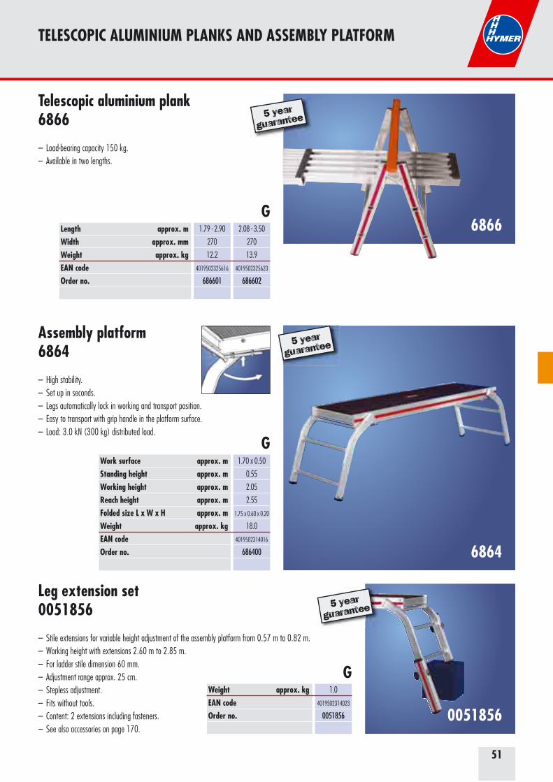
51
TELESCOPIC ALUMINIUM PLANKS AND ASSEMBLY PLATFORM
6864
Assembly platform6864
– High stability.– Set up in seconds.– Legs automatically lock in working and transport position. – Easy to transport with grip handle in the platform surface.– Load: 3.0 kN (300 kg) distributed load.
Leg extension set 0051856
– Stile extensions for variable height adjustment of the assembly platform from 0.57 m to 0.82 m.– Working height with extensions 2.60 m to 2.85 m.– For ladder stile dimension 60 mm.– Adjustment range approx. 25 cm.– Stepless adjustment.– Fits without tools.– Content: 2 extensions including fasteners.– See also accessories on page 170.
0051856
Work surface approx. mStanding height approx. mWorking height approx. mReach height approx. mFolded size L x W x H approx. mWeight approx. kgEAN codeOrder no.
1.70 x 0.50
0.55
2.05
2.55
1.75 x 0.60 x 0.20
18.0
4019502314016
686400
5 year
guarantee
5 year
guarantee
G
G
Telescopic aluminium plank6866
– Load-bearing capacity 150 kg.– Available in two lengths.
6866
5 year
guarantee
Length approx. mWidth approx. mmWeight approx. kgEAN codeOrder no.
1.79 - 2.90
270
12.2
4019502325616
686601
2.08 - 3.50
270
13.9
4019502325623
686602
G
Weight approx. kgEAN codeOrder no.
1.0
4019502314023
0051856
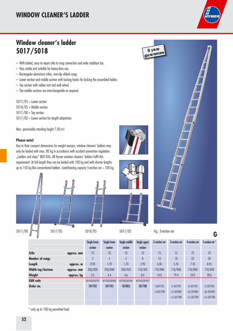
52
WINDOW CLEANER‘S LADDER
Fig.: 3-section set
Window cleaner‘s ladder5017/5018– With bolted, easy to repair stile to rung connection and wide stabiliser bar. – Very stable and suitable for heavy-duty use.– Rectangular aluminium stiles, non-slip ribbed rungs. – Lower section and middle section with locking hooks for locking the assembled ladder. – Top section with rubber rest and wall wheel. – The middle sections are interchangeable as required.
5017/05 = Lower section5018/05 = Middle section5017/08 = Top section5017/02 = Lower section for length adaptation
Max. permissible standing height 7.00 m!
Please note!Due to their compact dimensions for weight reasons, window cleaners‘ ladders may only be loaded with max. 80 kg in accordance with accident prevention regulation „Ladders and steps“ BGV D36. All Hymer window cleaners‘ ladders fulfil this requirement. At full length they can be loaded with 100 kg and with shorter lengths up to 150 kg like conventional ladders. Load-bearing capacity 5-section set = 100 kg.
* only up to 100 kg permitted load
5 year
guarantee
Stile approx. mm Number of rungsLength approx. mWidth top/bottom approx. mmWeight approx. kgEAN codeOrder no.
Single lower
section
73
2
0.90
350/830
3.5
4019502307797
501702
Single lower
section
73
5
1.70
350/840
6.4
4019502307803
501705
Single middle
section
73
5
1.70
350/435
4.6
4019502307841
501805
Single upper
section
73
8
2.90
110/435
8.4
4019502307827
501708
2-section set
73
13
4.30
110/840
14.8
1x501705
+1x501708
3-section set
73
18
5.70
110/840
19.4
1x 501705
+1x 501805
+1x 501708
4-section set
73
23
7.10
110/840
24.0
1x 501705
+2x 501805
+1x 501708
5-section set *
73
28
8.45
110/840
28.6
1x 501705
+3x 501805
+1x 501708
G5017/05 5018/05 5017/025017/08

53
ORCHARD LADDERS
3049
Orchard ladder complying with DIN 683633049
– Leaning ladder with guided aluminium supports for harvesting and tree care. – Standard 70 mm long aluminium tips. – Height-adjustable supports.– Permissible load = 1,000 N (approx. 100 kg).
3050
Two section orchard ladder complying with DIN 683633050– Extension ladder adjustable from rung to rung.– Lower section with guided supports. – Both ladder sections can also be used individually. – Standard 70 mm long aluminium tips. – Extension section protected against unintentional detachment. – Spreader function assured by adjustable, high-strength nylon straps. – Height-adjustable supports.– Permissible load = 1,000 N (approx. 100 kg).Attention: When in use as a two section ladder, it may not be used as a freestanding ladder, e.g. top section must be leant against a wall or tree.
Use only on firm ground.
Use only on firmground.
Number of rungsStile approx. mm No. of rungs at max. extentLength closed approx. mLength extended approx. mStanding height approx. mWorking height approx. mReach height approx. mWidth top/bottom approx. mmWeight approx. kgEAN codeOrder no.
2x10
60
18
3.12
5.35
3.85
5.35
5.85
355/355
15.0
4019502305717
305020
2x12
60
22
3.67
6.47
4.93
6.43
6.93
355/355
17.0
4019502305724
305024
2x14
60
26
4.24
7.59
6.02
7.52
8.02
355/355
19.0
4019502305731
305028
Number of rungsStile approx. mm Length approx. mStanding height approx. mWorking height approx. mReach height approx. mWidth approx. mmWeight approx. kgEAN codeOrder no.
12
60
3.67
2.23
3.73
4.23
355
10.0
4019502305670
304912
14
60
4.23
2.77
4.27
4.77
355
11.5
4019502305687
304914
5 year
guarantee
5 year
guarantee
S
S
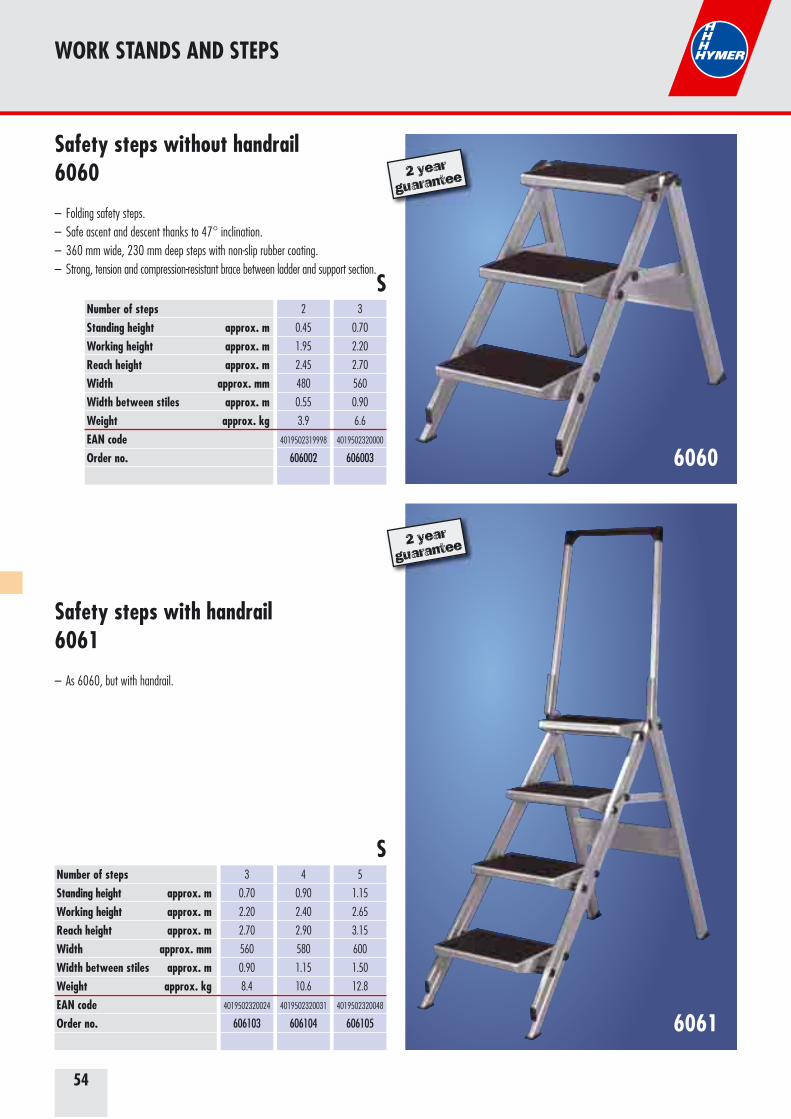
54
WORK STANDS AND STEPS
Safety steps without handrail6060
– Folding safety steps. – Safe ascent and descent thanks to 47° inclination.– 360 mm wide, 230 mm deep steps with non-slip rubber coating. – Strong, tension and compression-resistant brace between ladder and support section.
6061
Safety steps with handrail6061
– As 6060, but with handrail.
Number of steps Standing height approx. mWorking height approx. mReach height approx. mWidth approx. mmWidth between stiles approx. mWeight approx. kgEAN codeOrder no.
2
0.45
1.95
2.45
480
0.55
3.9
4019502319998
606002
3
0.70
2.20
2.70
560
0.90
6.6
4019502320000
606003
Number of steps Standing height approx. mWorking height approx. mReach height approx. mWidth approx. mmWidth between stiles approx. mWeight approx. kgEAN codeOrder no.
3
0.70
2.20
2.70
560
0.90
8.4
4019502320024
606103
4
0.90
2.40
2.90
580
1.15
10.6
4019502320031
606104
5
1.15
2.65
3.15
600
1.50
12.8
4019502320048
606105
S
S
2 year
guarantee
2 year
guarantee
6060
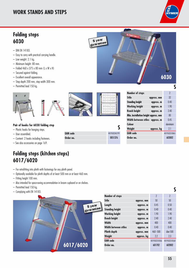
55
WORK STANDS AND STEPS
Folding steps6030– DIN EN 14183.– Easy to carry with practical carrying handle.– Low weight: 2.1 kg.– Minimum height: 80 mm.– Folded 460 x 375 x 80 mm (L x W x H)– Secured against folding.– Excellent overall appearance.– Step depth 200 mm, step width 300 mm.– Permitted load 150 kg.
Number of stepsStile approx. mm Standing height approx. mWorking height approx. mReach height approx. mMin. installation height approx. mmWidth between stiles approx. mColourWeight approx. kgEAN codeOrder no.
2
32
0.40
1.90
2.40
80
0.45
aluminium
2.1
4019502310865
603002
6017/6020
Folding steps (kitchen steps)6017/6020– For retrofitting into plinth with fastenings for any plinth panel. – Optionally available for plinth depths of at least 500 mm or at least 460 mm. – Fitting height 100 mm. – Also intended for space-saving accommodation in broom cupboard or on shelves. – Permitted load 150 kg. – Complying with EN 14183.
Number of stepsStile approx. mm Length approx. mStanding height approx. mWorking height approx. mReach height approx. mWidth approx. mmWidth between stiles approx. mPlinth depth approx. mmWeight approx. kgEAN codeOrder no.
2
50
0.50
0.40
1.90
2.40
400
0.40
über 500
2.3
4019502310568
602002
2
50
0.45
0.40
1.90
2.40
400
0.40
460 - 500
2.2
4019502310506
601702
S
S
5 year
guarantee
5 year
guarantee
6030
EAN codeOrder no.
4019502345799
0051376
SPair of hooks for 6030 folding step– Plastic hooks for hanging steps.– User assembled.– Content: 2 hooks including fasteners.– See also accessories on page 169.
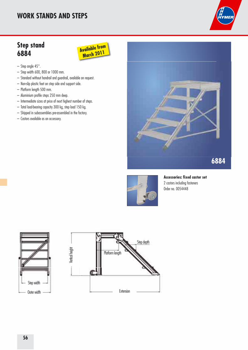
56
WORK STANDS AND STEPS
6884
Step stand 6884
– Step angle 45°.– Step width 600, 800 or 1000 mm.– Standard without handrail and guardrail, available on request.– Non-slip plastic feet on step side and support side.– Platform length 500 mm.– Aluminium profile steps 250 mm deep.– Intermediate sizes at price of next highest number of steps.– Total load-bearing capacity 300 kg, step load 150 kg.– Shipped in subassemblies pre-assembled in the factory.– Castors available as an accessory.
Accessories: fixed castor set2 castors including fastenersOrder no. 0054448
Extension
Platform length
Step depth
Step width
Outer width
Vertic
al he
ight
Available from
March 2011

57
WORK STANDS AND STEPS
Number of stepsStanding height approx. mExtension approx. mWeight approx. kgEAN codeOrder no.
2
0.40
0.75
7.9
4019502347212
68840602
3
0.60
0.94
11.9
4019502347229
68840603
4
0.80
1.14
15.8
4019502347236
68840604
Step width 600 mm
Number of stepsStanding height approx. mExtension approx. mWeight approx. kgEAN codeOrder no.
2
0.40
0.75
13.2
4019502347281
68841002
3
0.60
0.94
19.8
4019502347298
68841003
4
0.80
1.14
26.4
4019502347304
68841004
5
1.00
1.35
33.0
4019502347311
68841005
Step width 1000 mm
Number of stepsStanding height approx. mExtension approx. mWeight approx. kgEAN codeOrder no.
2
0.40
0.75
10.5
4019502347243
68840802
3
0.60
0.94
15.8
4019502347267
68840803
4
0.80
1.14
21.2
4019502347250
68840804
5
1.00
1.35
26.4
4019502347274
68840805
Step width 800 mm G
G
G
Platform extension including rail extension on request.Aluminium or steel grating steps on request.
Platform extension including rail extension on request.Aluminium or steel grating steps on request.
Platform extension including rail extension on request.Aluminium or steel grating steps on request.
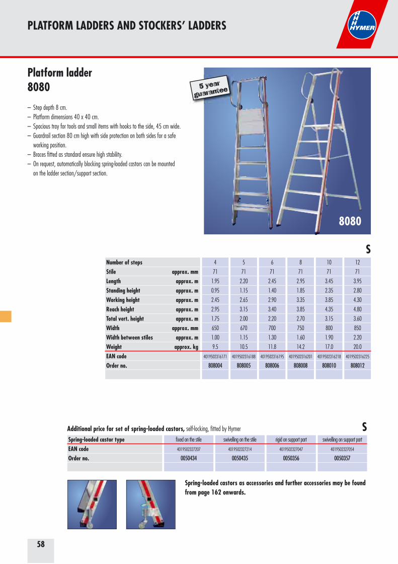
58
8080
Platform ladder8080
– Step depth 8 cm.– Platform dimensions 40 x 40 cm.– Spacious tray for tools and small items with hooks to the side, 45 cm wide.– Guardrail section 80 cm high with side protection on both sides for a safe working position.– Braces fitted as standard ensure high stability.– On request, automatically blocking spring-loaded castors can be mounted on the ladder section/support section.
PLATFORM LADDERS AND STOCKERS’ LADDERS
Number of stepsStile approx. mm Length approx. mStanding height approx. mWorking height approx. mReach height approx. mTotal vert. height approx. mWidth approx. mmWidth between stiles approx. mWeight approx. kgEAN codeOrder no.
4
71
1.95
0.95
2.45
2.95
1.75
650
1.00
9.5
4019502316171
808004
5
71
2.20
1.15
2.65
3.15
2.00
670
1.15
10.5
4019502316188
808005
6
71
2.45
1.40
2.90
3.40
2.20
700
1.30
11.8
4019502316195
808006
8
71
2.95
1.85
3.35
3.85
2.70
750
1.60
14.2
4019502316201
808008
10
71
3.45
2.35
3.85
4.35
3.15
800
1.90
17.0
4019502316218
808010
12
71
3.95
2.80
4.30
4.80
3.60
850
2.20
20.0
4019502316225
808012
S
5 year
guarantee
Spring-loaded castor typeEAN codeOrder no.
fixed on the stile
4019502327207
0050434
swivelling on the stile
4019502327214
0050435
rigid on support part
4019502327047
0050356
swivelling on support part
4019502327054
0050357
Additional price for set of spring-loaded castors, self-locking, fitted by Hymer S
Spring-loaded castors as accessories and further accessories may be found from page 162 onwards.
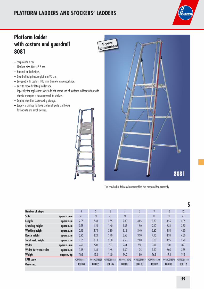
59
Platform ladder with castors and guardrail8081
– Step depth 8 cm.– Platform size 40 x 48.5 cm.– Handrail on both sides.– Guardrail height above platform 90 cm.– Equipped with castors, 100 mm diameter on support side.– Easy to move by lifting ladder side.– Especially for applications which do not permit use of platform ladders with a wide chassis or require a close approach to shelves.– Can be folded for space-saving storage.– Large 45 cm tray for tools and small parts and hooks for buckets and small devices.
8081
Number of stepsStile approx. mm Length approx. mStanding height approx. mWorking height approx. mReach height approx. mTotal vert. height approx. mWidth approx. mmWidth between stiles approx. mWeight approx. kgEAN codeOrder no.
4
71
2.05
0.95
2.45
2.95
1.85
650
1.15
10.5
4019502318311
808104
5
71
2.30
1.20
2.70
3.20
2.10
670
1.30
12.0
4019502318328
808105
6
71
2.55
1.40
2.90
3.40
2.30
700
1.45
13.0
4019502318335
808106
7
71
2.80
1.65
3.15
3.65
2.55
730
1.60
14.0
4019502318342
808107
8
71
3.05
1.90
3.40
3.90
2.80
750
1.75
15.0
4019502318359
808108
9
71
3.30
2.10
3.60
4.10
3.00
780
1.90
16.5
4019502318366
808109
10
71
3.55
2.34
3.84
4.34
3.25
800
2.05
17.5
4019502318373
808110
12
71
4.05
2.80
4.30
4.80
3.70
850
2.35
19.5
4019502318380
808112
PLATFORM LADDERS AND STOCKERS’ LADDERS
S
The handrail is delivered unassembled but prepared for assembly.
5 year
guarantee
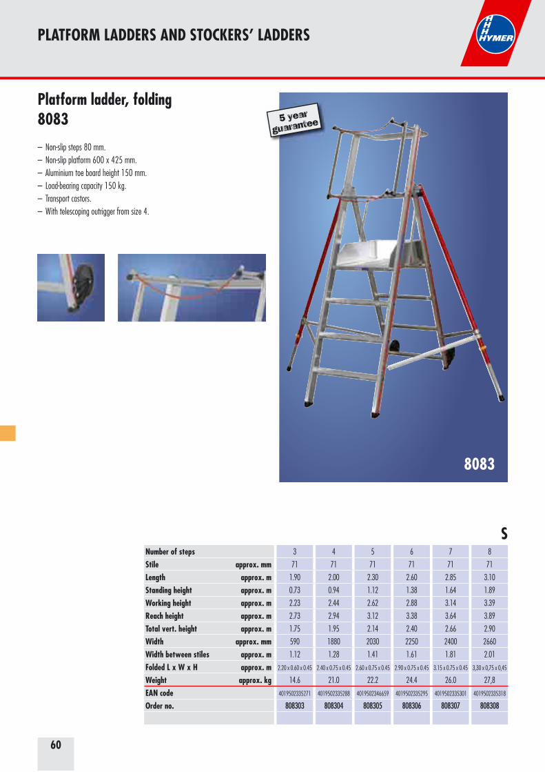
60
Platform ladder, folding8083
– Non-slip steps 80 mm.– Non-slip platform 600 x 425 mm.– Aluminium toe board height 150 mm.– Load-bearing capacity 150 kg.– Transport castors.– With telescoping outrigger from size 4.
8083
Number of stepsStile approx. mm Length approx. mStanding height approx. mWorking height approx. mReach height approx. mTotal vert. height approx. mWidth approx. mmWidth between stiles approx. mFolded L x W x H approx. mWeight approx. kgEAN codeOrder no.
3
71
1.90
0.73
2.23
2.73
1.75
590
1.12
2.20 x 0.60 x 0.45
14.6
4019502335271
808303
4
71
2.00
0.94
2.44
2.94
1.95
1880
1.28
2.40 x 0.75 x 0.45
21.0
4019502335288
808304
5
71
2.30
1.12
2.62
3.12
2.14
2030
1.41
2.60 x 0.75 x 0.45
22.2
4019502346659
808305
6
71
2.60
1.38
2.88
3.38
2.40
2250
1.61
2.90 x 0.75 x 0.45
24.4
4019502335295
808306
7
71
2.85
1.64
3.14
3.64
2.66
2400
1.81
3.15 x 0.75 x 0.45
26.0
4019502335301
808307
8
71
3.10
1.89
3.39
3.89
2.90
2660
2.01
3,30 x 0,75 x 0,45
27,8
4019502335318
808308
S
PLATFORM LADDERS AND STOCKERS’ LADDERS
5 year
guarantee
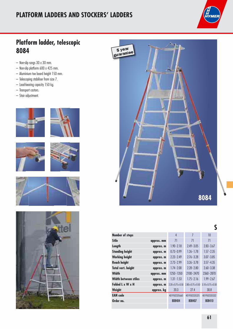
61
8084
Platform ladder, telescopic8084
– Non-slip rungs 30 x 30 mm.– Non-slip platform 600 x 425 mm.– Aluminium toe board height 150 mm.– Telescoping stabiliser from size 7.– Load-bearing capacity 150 kg.– Transport castors.– Stair adjustment.
Number of stepsStile approx. mm Length approx. mStanding height approx. mWorking height approx. mReach height approx. mTotal vert. height approx. mWidth approx. mmWidth between stiles approx. mFolded L x W x H approx. mWeight approx. kgEAN codeOrder no.
4
71
1.90 - 2.18
0.73 - 0.99
2.23 - 2.49
2.73 - 2.99
1.74 - 2.00
1250 - 1350
1.31 - 1.53
2.20 x 0.75 x 0.50
20.3
4019502335660
808404
7
71
2.49 - 3.05
1.26 - 1.78
2.76 - 3.28
3.26 - 3.78
2.28 - 2.80
2100 - 2470
1.75 - 2.16
2.80 x 0.75 x 0.50
27.4
4019502335325
808407
10
71
2.83 - 3.67
1.57 - 2.35
3.07 - 3.85
3.57 - 4.35
2.60 - 3.38
2360 - 2870
1.99 - 2.67
3.10 x 0.75 x 0.50
30.8
4019502335332
808410
S
5 year
guarantee
PLATFORM LADDERS AND STOCKERS’ LADDERS
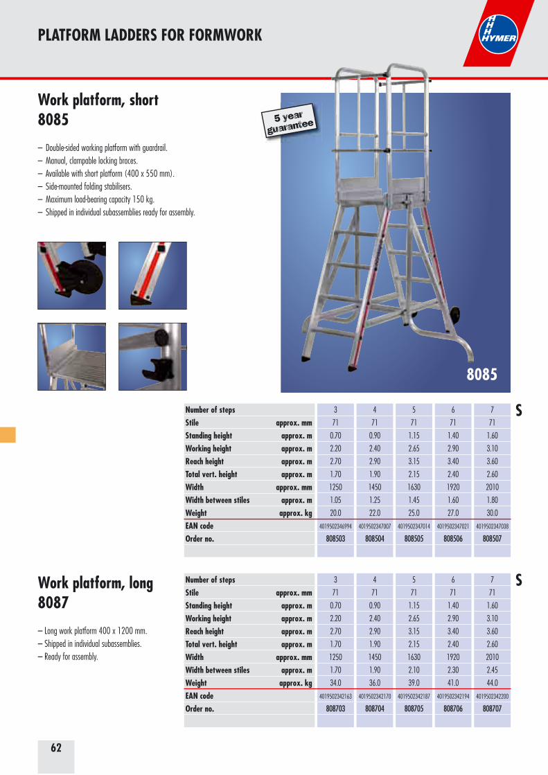
62
8085
Work platform, short8085
– Double-sided working platform with guardrail.– Manual, clampable locking braces. – Available with short platform (400 x 550 mm). – Side-mounted folding stabilisers. – Maximum load-bearing capacity 150 kg. – Shipped in individual subassemblies ready for assembly.
PLATFORM LADDERS FOR FORMWORK
5 year
guarantee
Work platform, long8087
– Long work platform 400 x 1200 mm.– Shipped in individual subassemblies. – Ready for assembly.
Number of stepsStile approx. mmStanding height approx. mWorking height approx. mReach height approx. mTotal vert. height approx. mWidth approx. mmWidth between stiles approx. mWeight approx. kgEAN codeOrder no.
3
71
0.70
2.20
2.70
1.70
1250
1.05
20.0
4019502346994
808503
4
71
0.90
2.40
2.90
1.90
1450
1.25
22.0
4019502347007
808504
5
71
1.15
2.65
3.15
2.15
1630
1.45
25.0
4019502347014
808505
6
71
1.40
2.90
3.40
2.40
1920
1.60
27.0
4019502347021
808506
7
71
1.60
3.10
3.60
2.60
2010
1.80
30.0
4019502347038
808507
3
71
0.70
2.20
2.70
1.70
1250
1.70
34.0
4019502342163
808703
4
71
0.90
2.40
2.90
1.90
1450
1.90
36.0
4019502342170
808704
5
71
1.15
2.65
3.15
2.15
1630
2.10
39.0
4019502342187
808705
6
71
1.40
2.90
3.40
2.40
1920
2.30
41.0
4019502342194
808706
7
71
1.60
3.10
3.60
2.60
2010
2.45
44.0
4019502342200
808707
Number of stepsStile approx. mmStanding height approx. mWorking height approx. mReach height approx. mTotal vert. height approx. mWidth approx. mmWidth between stiles approx. mWeight approx. kgEAN codeOrder no.
S
S
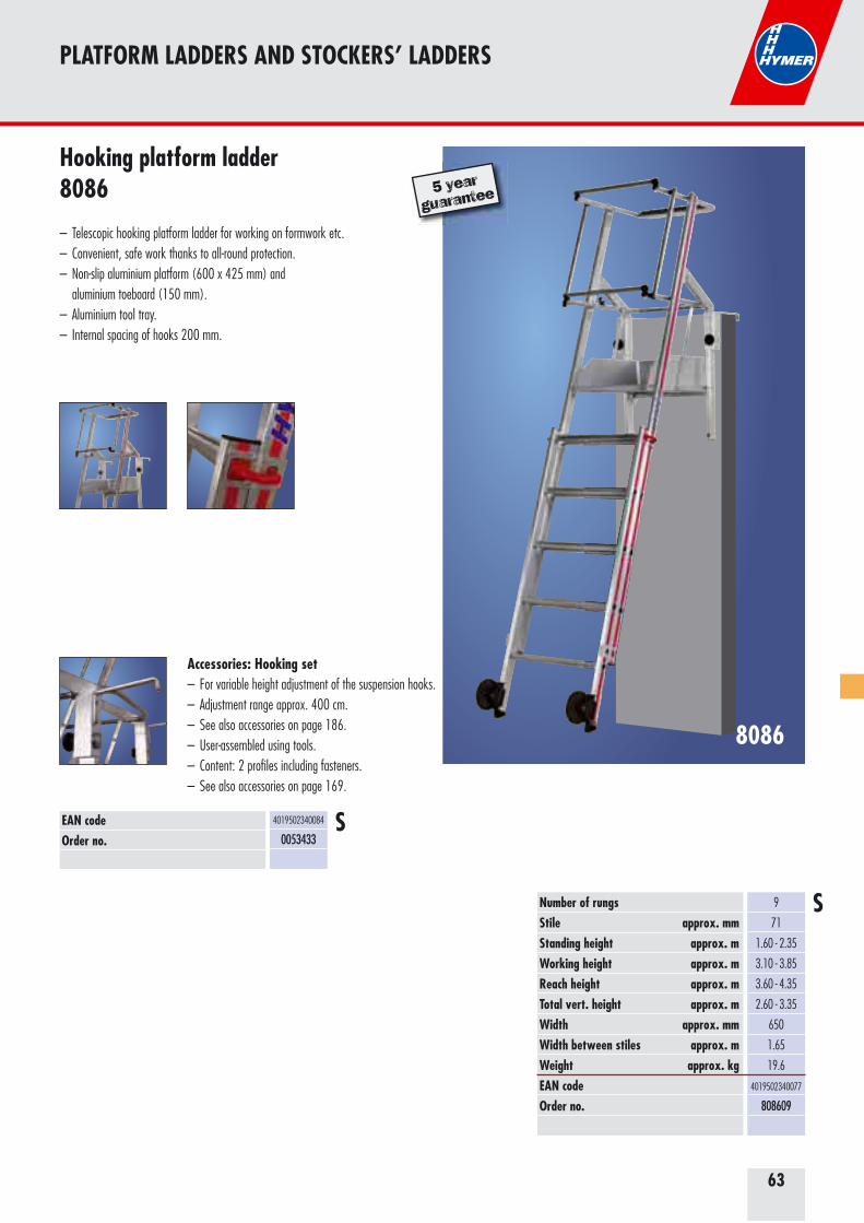
63
Hooking platform ladder8086
– Telescopic hooking platform ladder for working on formwork etc. – Convenient, safe work thanks to all-round protection. – Non-slip aluminium platform (600 x 425 mm) and aluminium toeboard (150 mm).– Aluminium tool tray. – Internal spacing of hooks 200 mm.
9
71
1.60 - 2.35
3.10 - 3.85
3.60 - 4.35
2.60 - 3.35
650
1.65
19.6
4019502340077
808609
Number of rungsStile approx. mmStanding height approx. m Working height approx. mReach height approx. mTotal vert. height approx. mWidth approx. mmWidth between stiles approx. mWeight approx. kgEAN codeOrder no.
PLATFORM LADDERS AND STOCKERS’ LADDERS
8086
5 year
guarantee
Accessories: Hooking set– For variable height adjustment of the suspension hooks.– Adjustment range approx. 400 cm.– See also accessories on page 186.– User-assembled using tools.– Content: 2 profiles including fasteners.– See also accessories on page 169.
4019502340084
0053433EAN codeOrder no.
S
S
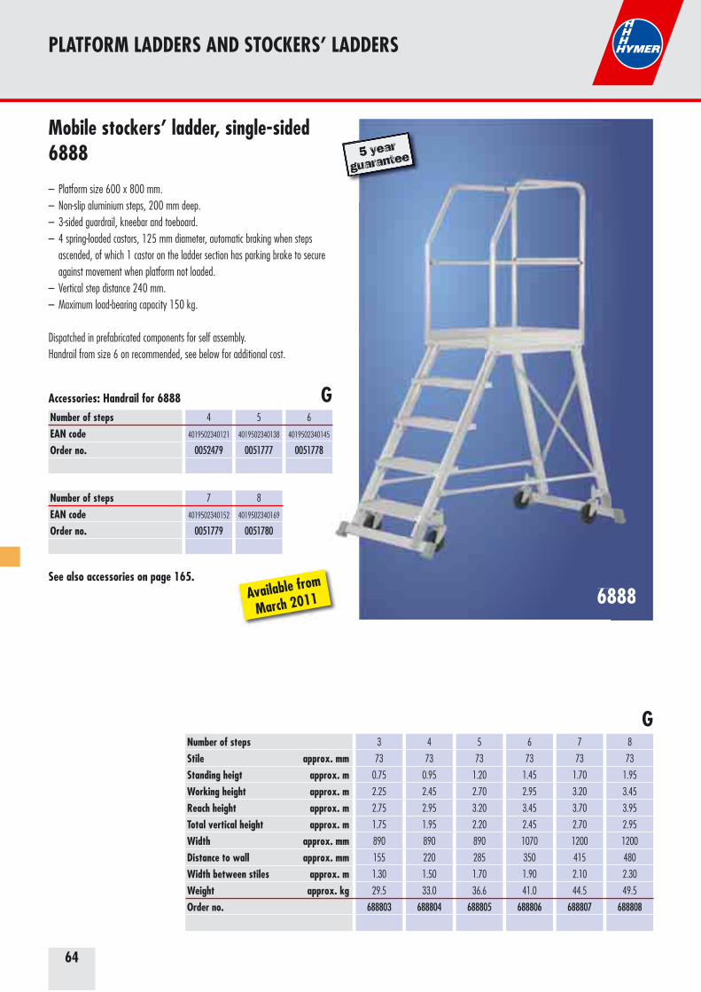
64
Mobile stockers’ ladder, single-sided6888
– Platform size 600 x 800 mm.– Non-slip aluminium steps, 200 mm deep.– 3-sided guardrail, kneebar and toeboard.– 4 spring-loaded castors, 125 mm diameter, automatic braking when steps ascended, of which 1 castor on the ladder section has parking brake to secure against movement when platform not loaded.– Vertical step distance 240 mm.– Maximum load-bearing capacity 150 kg.
Dispatched in prefabricated components for self assembly.Handrail from size 6 on recommended, see below for additional cost.
6888
PLATFORM LADDERS AND STOCKERS’ LADDERS
Number of stepsStile approx. mm Standing heigt approx. mWorking height approx. mReach height approx. mTotal vertical height approx. mWidth approx. mmDistance to wall approx. mmWidth between stiles approx. mWeight approx. kgOrder no.
3
73
0.75
2.25
2.75
1.75
890
155
1.30
29.5
688803
4
73
0.95
2.45
2.95
1.95
890
220
1.50
33.0
688804
5
73
1.20
2.70
3.20
2.20
890
285
1.70
36.6
688805
6
73
1.45
2.95
3.45
2.45
1070
350
1.90
41.0
688806
7
73
1.70
3.20
3.70
2.70
1200
415
2.10
44.5
688807
8
73
1.95
3.45
3.95
2.95
1200
480
2.30
49.5
688808
5 year
guarantee
re
6888
5 year
guarantee
GNumber of steps EAN codeOrder no.
Number of steps EAN codeOrder no.
4
4019502340121
0052479
7
4019502340152
0051779
5
4019502340138
0051777
8
4019502340169
0051780
6
4019502340145
0051778
See also accessories on page 165.
Accessories: Handrail for 6888
Available from
March 2011
G
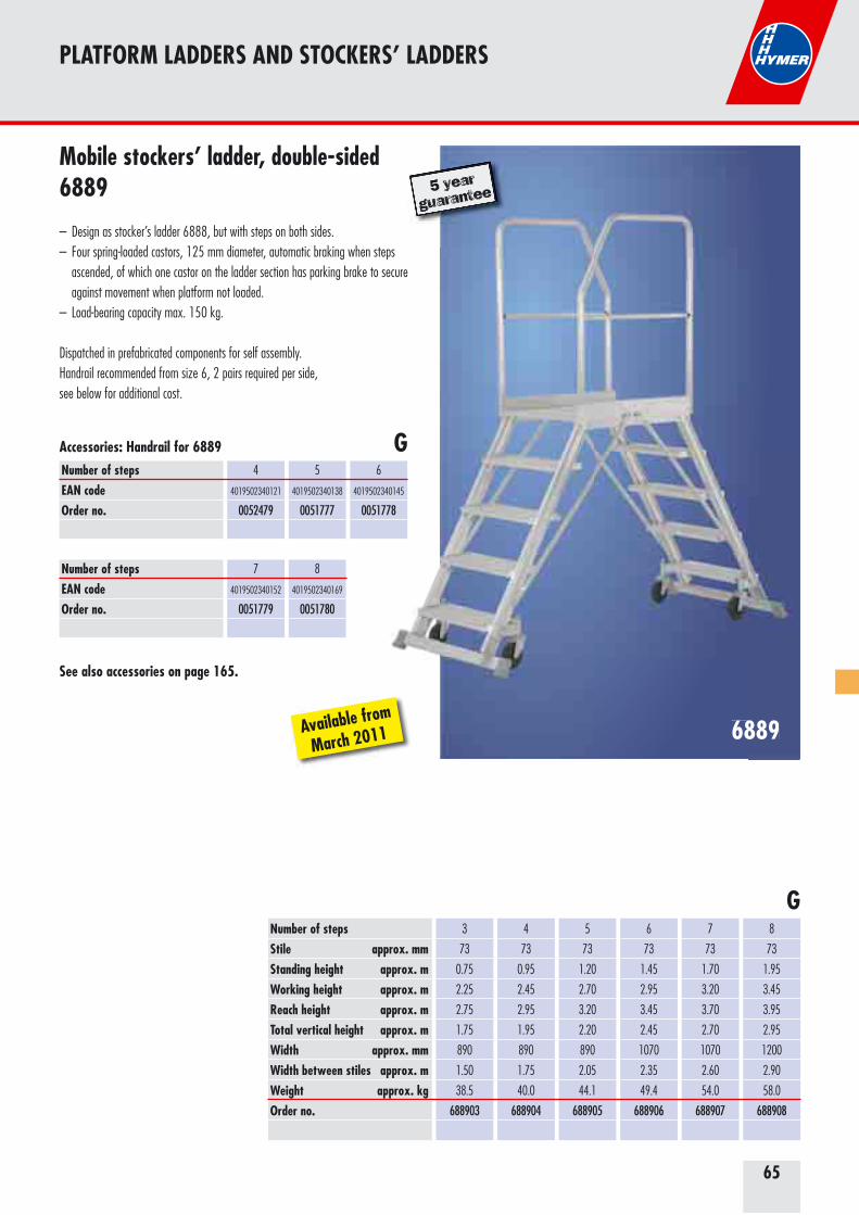
65
6889
Number of stepsStile approx. mm Standing height approx. mWorking height approx. mReach height approx. mTotal vertical height approx. mWidth approx. mmWidth between stiles approx. mWeight approx. kgOrder no.
3
73
0.75
2.25
2.75
1.75
890
1.50
38.5
688903
4
73
0.95
2.45
2.95
1.95
890
1.75
40.0
688904
5
73
1.20
2.70
3.20
2.20
890
2.05
44.1
688905
6
73
1.45
2.95
3.45
2.45
1070
2.35
49.4
688906
7
73
1.70
3.20
3.70
2.70
1070
2.60
54.0
688907
8
73
1.95
3.45
3.95
2.95
1200
2.90
58.0
688908
G
PLATFORM LADDERS AND STOCKERS’ LADDERS
5 year
guarantee
6889
5 year
guarantee
Mobile stockers’ ladder, double-sided6889
– Design as stocker’s ladder 6888, but with steps on both sides.– Four spring-loaded castors, 125 mm diameter, automatic braking when steps ascended, of which one castor on the ladder section has parking brake to secure against movement when platform not loaded.– Load-bearing capacity max. 150 kg.
Dispatched in prefabricated components for self assembly.Handrail recommended from size 6, 2 pairs required per side,see below for additional cost.
GNumber of steps EAN codeOrder no.
Number of steps EAN codeOrder no.
4
4019502340121
0052479
7
4019502340152
0051779
5
4019502340138
0051777
8
4019502340169
0051780
6
4019502340145
0051778
See also accessories on page 165.
Accessories: Handrail for 6889
Available from
March 2011
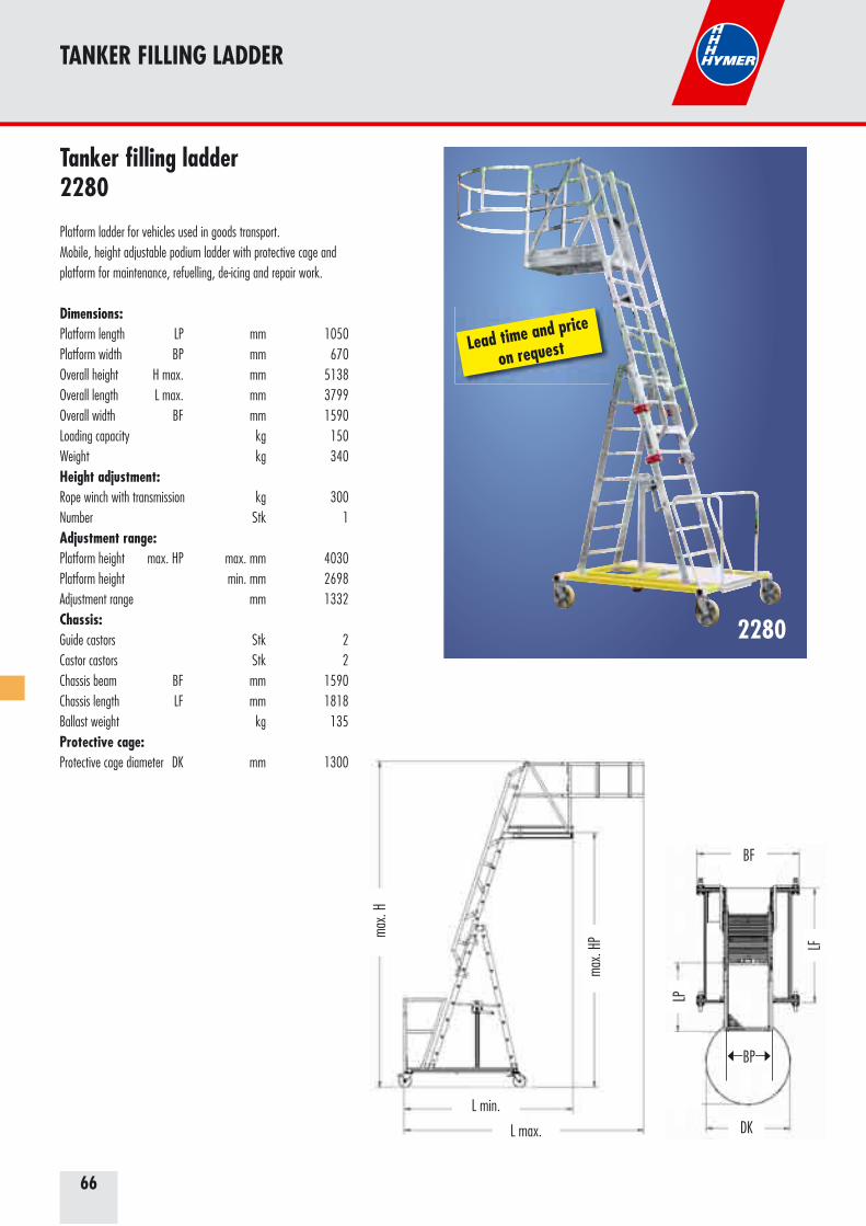
66
TANKER FILLING LADDER
Tanker filling ladder2280
Platform ladder for vehicles used in goods transport.Mobile, height adjustable podium ladder with protective cage and platform for maintenance, refuelling, de-icing and repair work.
Dimensions:Platform length LP mm 1050Platform width BP mm 670Overall height H max. mm 5138Overall length L max. mm 3799Overall width BF mm 1590Loading capacity kg 150Weight kg 340Height adjustment:Rope winch with transmission kg 300Number Stk 1Adjustment range:Platform height max. HP max. mm 4030Platform height min. mm 2698Adjustment range mm 1332Chassis:Guide castors Stk 2Castor castors Stk 2Chassis beam BF mm 1590Chassis length LF mm 1818Ballast weight kg 135Protective cage:Protective cage diameter DK mm 1300
Ha,
ges
Ha
La,max
La,min
Lf
Lp
Dk
Lk
Be
Bf
Bp
max
. H
L min.
L max.
max
. HP
BF
LP
LF
DK
BP
Lead time and price
on request
2280
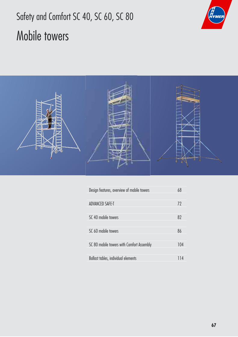
67
Design features, overview of mobile towers 68
ADVANCED SAFE-T 72
SC 40 mobile towers 82
SC 60 mobile towers 86
SC 80 mobile towers with Comfort Assembly 104
Ballast tables, individual elements 114
Safety and Comfort SC 40, SC 60, SC 80
Mobile towers
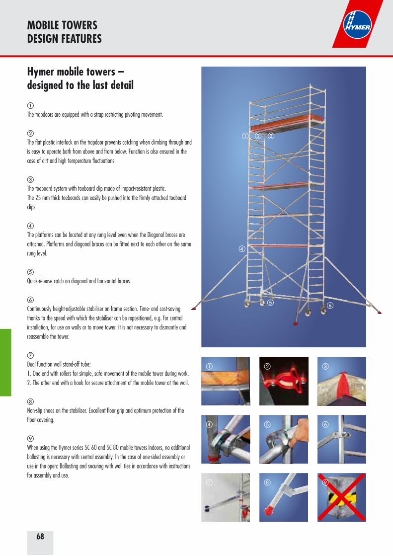
68
MOBILE TOWERSDESIGN FEATURES
Hymer mobile towers –designed to the last detail
�
The trapdoors are equipped with a strap restricting pivoting movement.
�
The flat plastic interlock on the trapdoor prevents catching when climbing through and is easy to operate both from above and from below. Function is also ensured in the case of dirt and high temperature fluctuations.
�
The toeboard system with toeboard clip made of impact-resistant plastic.The 25 mm thick toeboards can easily be pushed into the firmly attached toeboard clips.
�
The platforms can be located at any rung level even when the Diagonal braces are attached. Platforms and diagonal braces can be fitted next to each other on the same rung level.
�
Quick-release catch on diagonal and horizontal braces.
�
Continuously height-adjustable stabiliser on frame section. Time- and cost-saving thanks to the speed with which the stabiliser can be repositioned, e.g. for central installation, for use on walls or to move tower. It is not necessary to dismantle and reassemble the tower.
�
Dual function wall stand-off tube:1. One end with rollers for simple, safe movement of the mobile tower during work.2. The other end with a hook for secure attachment of the mobile tower at the wall.
Non-slip shoes on the stabiliser. Excellent floor grip and optimum protection of the floor covering.
When using the Hymer series SC 60 and SC 80 mobile towers indoors, no additional ballasting is necessary with central assembly. In the case of one-sided assembly or use in the open: Ballasting and securing with wall ties in accordance with instructions for assembly and use.
� � �
� � �
�
��
�
� � �
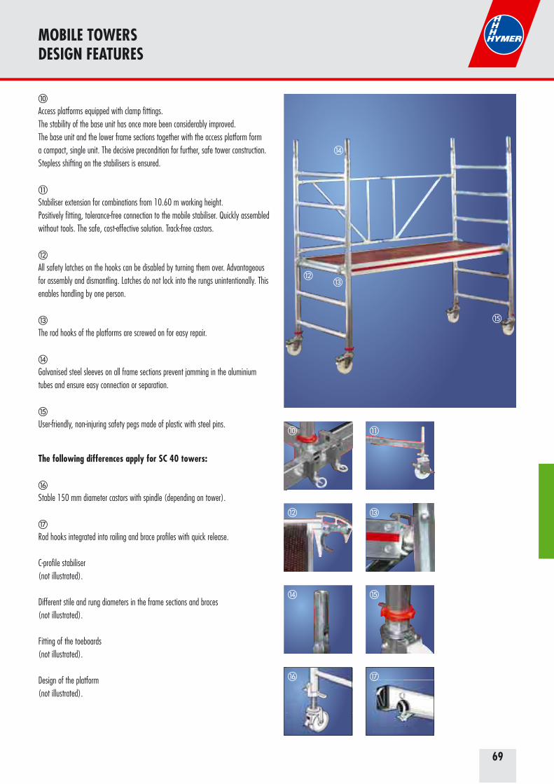
69
MOBILE TOWERSDESIGN FEATURES
�
Access platforms equipped with clamp fittings.The stability of the base unit has once more been considerably improved.The base unit and the lower frame sections together with the access platform form a compact, single unit. The decisive precondition for further, safe tower construction. Stepless shifting on the stabilisers is ensured.
�
Stabiliser extension for combinations from 10.60 m working height.Positively fitting, tolerance-free connection to the mobile stabiliser. Quickly assembled without tools. The safe, cost-effective solution. Track-free castors.
All safety latches on the hooks can be disabled by turning them over. Advantageous for assembly and dismantling. Latches do not lock into the rungs unintentionally. This enables handling by one person.
�
The rod hooks of the platforms are screwed on for easy repair.
�
Galvanised steel sleeves on all frame sections prevent jamming in the aluminium tubes and ensure easy connection or separation.
�
User-friendly, non-injuring safety pegs made of plastic with steel pins.
The following differences apply for SC 40 towers:
�
Stable 150 mm diameter castors with spindle (depending on tower).
�
Rod hooks integrated into railing and brace profiles with quick release.
C-profile stabiliser(not illustrated).
Different stile and rung diameters in the frame sections and braces(not illustrated).
Fitting of the toeboards (not illustrated).
Design of the platform(not illustrated).
� �
�
� �
�
�
�
� �
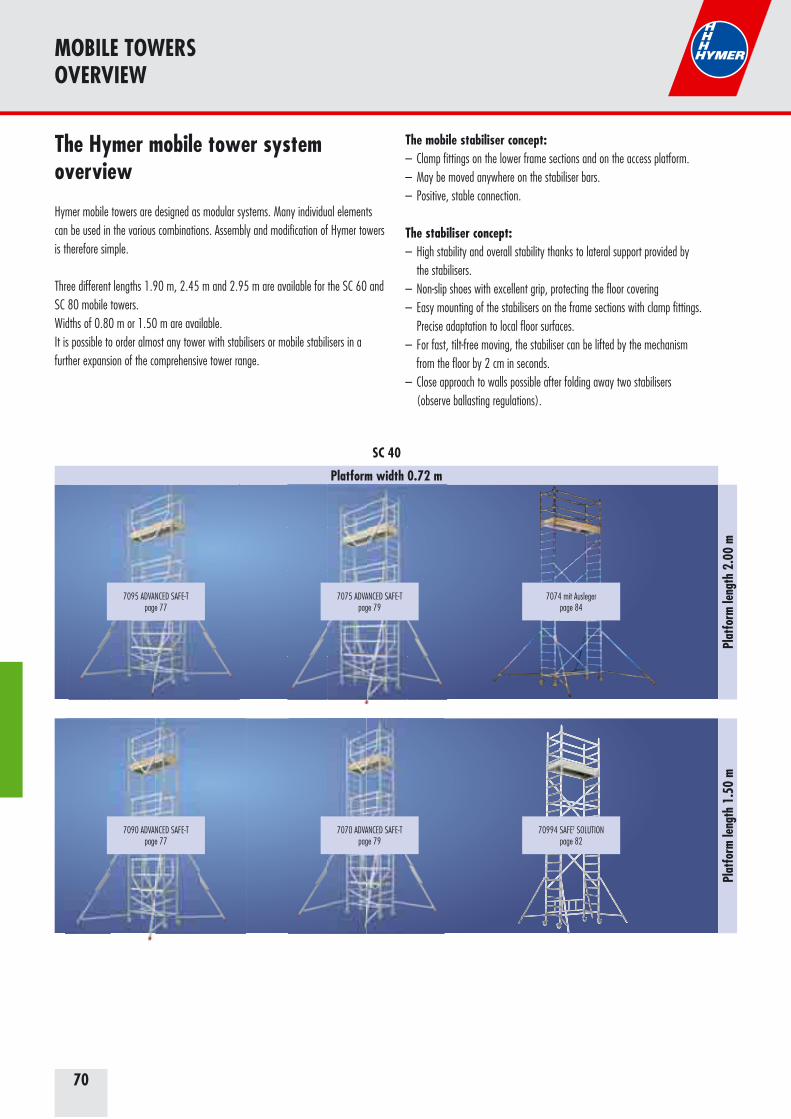
70
The Hymer mobile tower system overview
Hymer mobile towers are designed as modular systems. Many individual elements can be used in the various combinations. Assembly and modification of Hymer towers is therefore simple.
Three different lengths 1.90 m, 2.45 m and 2.95 m are available for the SC 60 and SC 80 mobile towers.Widths of 0.80 m or 1.50 m are available.It is possible to order almost any tower with stabilisers or mobile stabilisers in a further expansion of the comprehensive tower range.
MOBILE TOWERSOVERVIEW
The mobile stabiliser concept:– Clamp fittings on the lower frame sections and on the access platform.– May be moved anywhere on the stabiliser bars.– Positive, stable connection.
The stabiliser concept:– High stability and overall stability thanks to lateral support provided by the stabilisers.– Non-slip shoes with excellent grip, protecting the floor covering– Easy mounting of the stabilisers on the frame sections with clamp fittings. Precise adaptation to local floor surfaces.– For fast, tilt-free moving, the stabiliser can be lifted by the mechanism from the floor by 2 cm in seconds.– Close approach to walls possible after folding away two stabilisers (observe ballasting regulations).
Plat
form
leng
th 1
.50
m
Platform width 0.72 m
Plat
form
leng
th 2
.00
m
SC 40
7074 mit Auslegerpage 84
70994 SAFET SOLUTIONpage 82
7090 ADVANCED SAFE-Tpage 77
7095 ADVANCED SAFE-Tpage 77
7070 ADVANCED SAFE-Tpage 79
7075 ADVANCED SAFE-Tpage 79
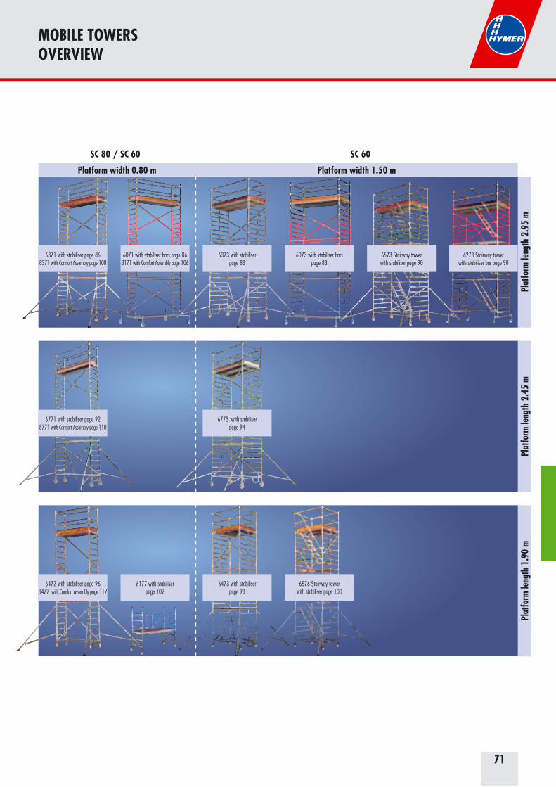
71
MOBILE TOWERSOVERVIEW
6371 with stabiliser page 868371 with Comfort Assembly page 108
6273 Stairway towerwith stabiliser bar page 90
6573 Stairway towerwith stabiliser page 90
6073 with stabiliser bars page 88
6373 with stabiliser page 88
6071 with stabiliser bars page 868171 with Comfort Assembly page 106
Platform width 0.80 m Platform width 1.50 m
Plat
form
leng
th 1
.90
mPl
atfo
rm le
ngth
2.9
5 m
Plat
form
leng
th 2
.45
m
6771 with stabiliser page 928771 with Comfort Assembly page 110
6773 with stabiliser page 94
6472 with stabiliser page 968472 with Comfort Assembly page 112
6576 Stairway towerwith stabiliser page 100
6473 with stabiliser page 98
SC 80 / SC 60 SC 60
6177 with stabiliser page 102
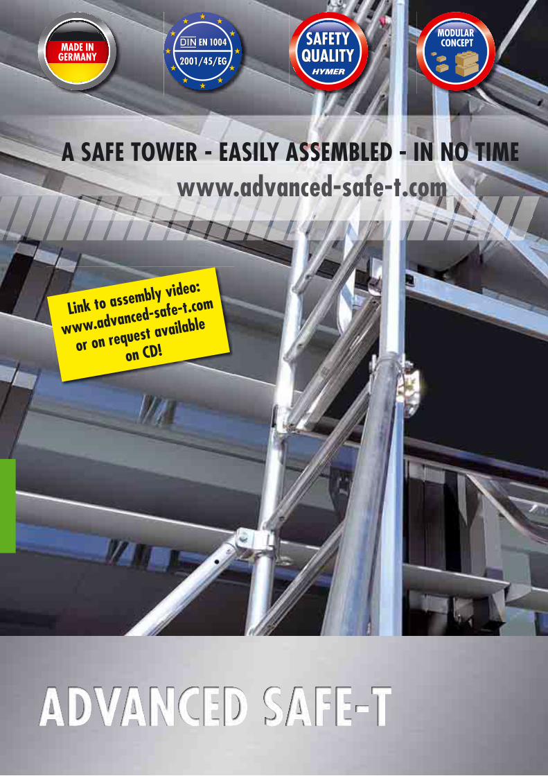
A SAFE TOWER - EASILY ASSEMBLED - IN NO TIME www.advanced-safe-t.com
Link to assembly video:
www.advanced-safe-t.com
or on request available
on CD!
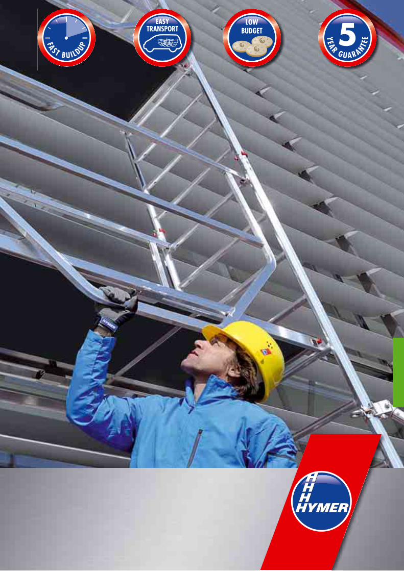

74
ADVANCED SAFE-T is of course certified to EN 1004. With ADVANCED SAFE-T, you are perfectly equipped to comply with the EU Directive 2001/45/EC.
Ideal for craftsmen and practical: ADVANCED SAFE-T offers maximum perfor-mance at a low price.
Lightweight and a small number of components with compact dimensions: It could not be more secure when erected or easier to transport.
ADVANCED SAFE-T has a modular design: You can quickly and easily determine the reach height you require by the number of modules.
ADVANCED SAFE-T with the new safety guardrail maximises safety for work at elevated locations.
Quality feature: Hymer-Leichtmetallbau offers an extended 5 year guarantee on ADVANCED SAFE-T.
ADVANCED SAFE-T is completely produced in Germany.
ADVANCED SAFE-T sets completely new standardsThe EU Directive 2001/45/EC is applicable for occupational safety law. It provides that wherever previously it was permitted to work with ladders, from now on mobile towers must be used, with a few exceptions.Hymer-Leichtmetallbau has now reacted to this situation with two innovative mobile towers for indoor and outdoor use which bridge the gap between ladders and scaffolding:ADVANCED SAFE-T
ADVANCED SAFE-T offers many advantages
components being missing at the construction site and therefore being omitted.
dimensions which fit into almost every commercial vehicle (estate car/transporter).
of the cost/benefit ratio.
CLEAR THE STAGE FOR NEW DIMENSIONS
THE ADVANCED SAFE-T MOBILE TOWER

75Link to assembly video: www.advanced-safe-t.com
A strong duo for all eventualities The new mobile tower is available in two different basic versions:
preferably in the interior, at reach heights of 3 m, 5 m and 7 m.
uneven ground, at reach heights of 3 m, 5 m, 7 m, 9 m and 11 m*.
All modules build consistently on each other Both types of ADVANCED SAFE-T are available in modules which build on one another so as to be able to reach different reach heights. Thus, the specialist dealer and skilled trade business has even more advantages:
At any time, the skilled tradesman can extend his Advanced Safe-T with further modules to increase the maximum reach height of his tower.
2 min 4 min 6 min 10 min8 min 12 min
In only 12 minutes from 0 to 7 m: A real alternative to ladders comprising just a few sections which can be mounted very easily, safely and quickly.
The newly developed safety guardrail attached from below provides indispen-sable side protection during assembly and dismantling. The safety guardrail is simply latched into the tower board and locked via self-locking hooks.
ddduuuooo AAAA sstrrrrooooonnnglf lll
eeeee nn n n nn nnnnThehehe nnnnnnnnabsabsababbbbsabllsabsabsasasaasable le e
sisimsimsimsimisimmplyplyply
* According to EN 1004, reach heights of 10 m and more are permissible only in the interior.
THE ADVANCED SAFE-T MOBILE TOWER
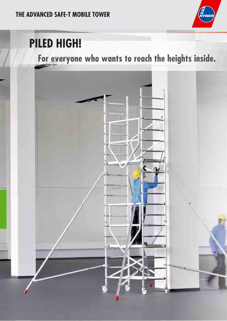
76
THE ADVANCED SAFE-T MOBILE TOWER
7676767676767676767676767676767676767677676767676676776767677667
PILED HIGH! For everyone who wants to reach the heights inside.
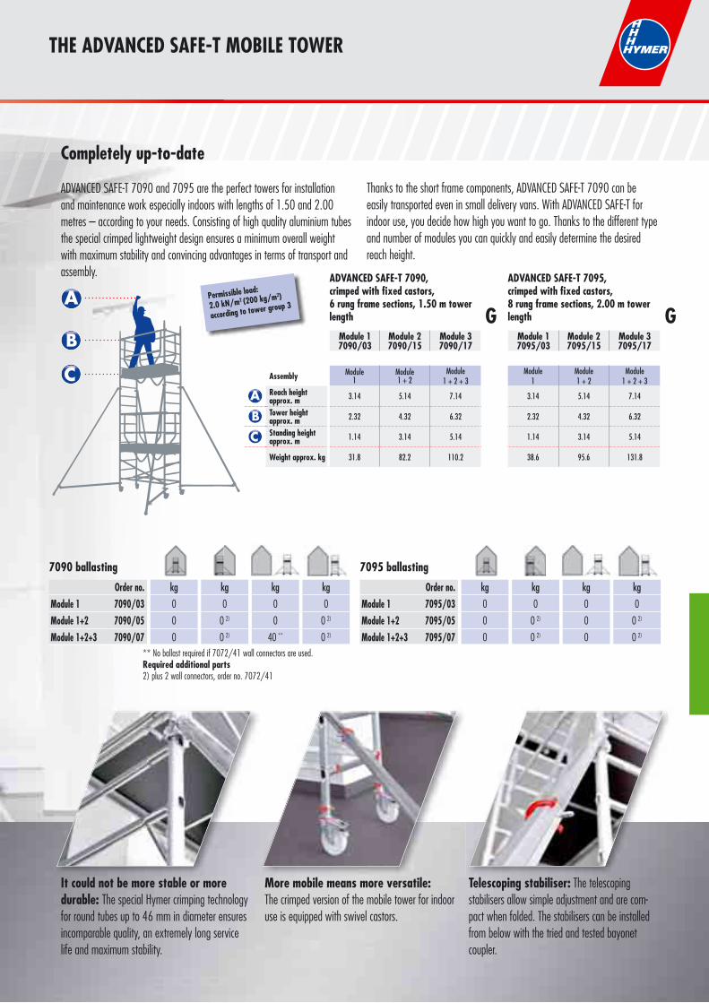
77
THE ADVANCED SAFE-T MOBILE TOWER
It could not be more stable or more durable: The special Hymer crimping technology for round tubes up to 46 mm in diameter ensures incomparable quality, an extremely long service life and maximum stability.
More mobile means more versatile: The crimped version of the mobile tower for indoor use is equipped with swivel castors.
Telescoping stabiliser: The telescoping stabilisers allow simple adjustment and are com-pact when folded. The stabilisers can be installed from below with the tried and tested bayonet coupler.
Permissible load:
2.0 kN/m2 (200 kg/m2)
according to tower group 3
Assembly Module1
Module 1 + 2
Module 1 + 2 + 3
Module1
Module1 + 2
Module1 + 2 + 3
Reach height approx. m 3.14 5.14 7.14 3.14 5.14 7.14
Tower height approx. m 2.32 4.32 6.32 2.32 4.32 6.32
Standing height approx. m 1.14 3.14 5.14 1.14 3.14 5.14
Weight approx. kg 31.8 82.2 110.2 38.6 95.6 131.8
Module 1 7090/03
Module 27090/15
Module 37090/17
ADVANCED SAFE-T 7095, crimped with fixed castors, 8 rung frame sections, 2.00 m tower length
Module 1 7095/03
Module 27095/15
Module 37095/17
G G
7090 ballasting
Order no.Module 1 7090/03Module 1+2 7090/05Module 1+2+3 7090/07
kg
0
0 2)
0 2)
kg
0
0
40 **
kg
0
0 2)
0 2)
kg
0
0
0
7095 ballasting
Order no.Module 1 7095/03Module 1+2 7095/05Module 1+2+3 7095/07
kg
0
0 2)
0 2)
kg
0
0
0
kg
0
0 2)
0 2)
kg
0
0
0
Thanks to the short frame components, ADVANCED SAFE-T 7090 can be easily transported even in small delivery vans. With ADVANCED SAFE-T for indoor use, you decide how high you want to go. Thanks to the different type and number of modules you can quickly and easily determine the desired reach height.
ADVANCED SAFE-T 7090, crimped with fixed castors, 6 rung frame sections, 1.50 m tower length
Completely up-to-date
ADVANCED SAFE-T 7090 and 7095 are the perfect towers for installation and maintenance work especially indoors with lengths of 1.50 and 2.00 metres – according to your needs. Consisting of high quality aluminium tubes the special crimped lightweight design ensures a minimum overall weight with maximum stability and convincing advantages in terms of transport and assembly.
** No ballast required if 7072/41 wall connectors are used.Required additional parts2) plus 2 wall connectors, order no. 7072/41
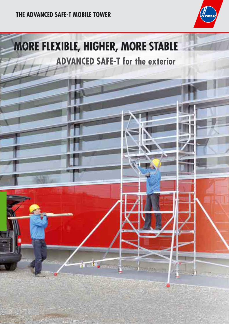
78
THE ADVANCED SAFE-T MOBILE TOWER
7878787878787877777787878787878787878787878787878787877777878787878787877877887787778787877787777778877878788787878787877787878787787877877877777878787777877878777777878778778778888887878877888878787878877878888787788887788877
MORE FLEXIBLE, HIGHER, MORE STABLE ADVANCED SAFE-T for the exterior
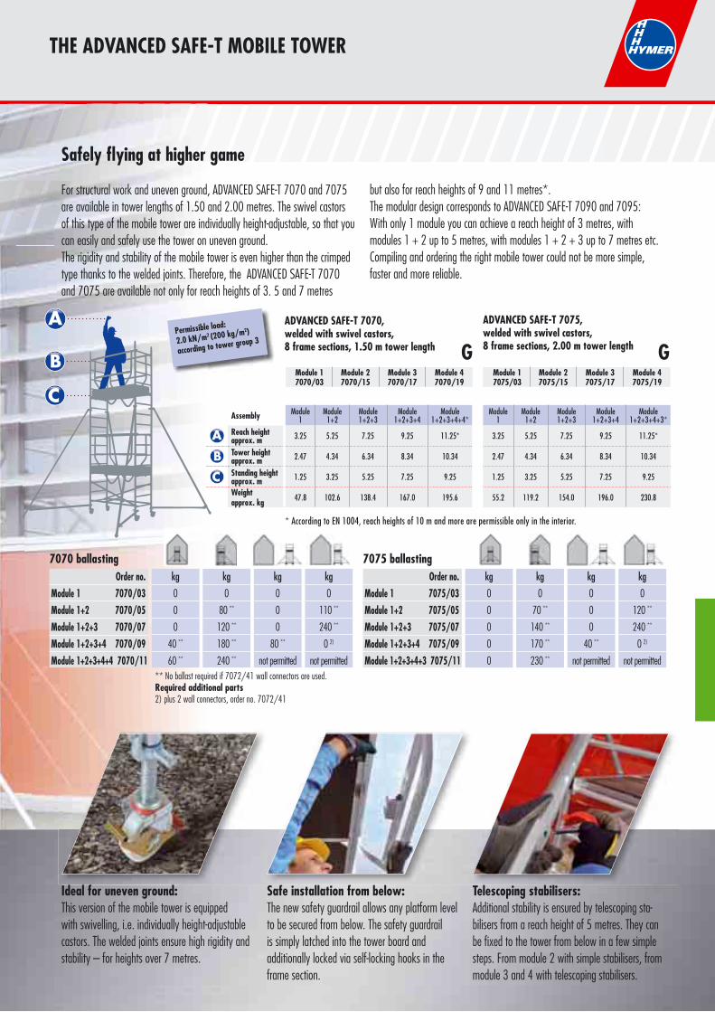
79
THE ADVANCED SAFE-T MOBILE TOWER
Ideal for uneven ground: This version of the mobile tower is equipped with swivelling, i.e. individually height-adjustable castors. The welded joints ensure high rigidity and stability – for heights over 7 metres.
Safe installation from below: The new safety guardrail allows any platform level to be secured from below. The safety guardrail is simply latched into the tower board and additionally locked via self-locking hooks in the frame section.
Telescoping stabilisers: Additional stability is ensured by telescoping sta-bilisers from a reach height of 5 metres. They can be fixed to the tower from below in a few simple steps. From module 2 with simple stabilisers, from module 3 and 4 with telescoping stabilisers.
dddd ll fff dddddd ff lll ff bbb ll lll bbbb ll
Permissible load:
2.0 kN/m2 (200 kg/m2)
according to tower group 3
Assembly Module1
Module 1+2
Module 1+2+3
Module 1+2+3+4
Module1+2+3+4+4*
Module1
Module1+2
Module1+2+3
Module 1+2+3+4
Module 1+2+3+4+3*
Reach height approx. m 3.25 5.25 7.25 9.25 11.25* 3.25 5.25 7.25 9.25 11.25*
Tower height approx. m 2.47 4.34 6.34 8.34 10.34 2.47 4.34 6.34 8.34 10.34
Standing height approx. m 1.25 3.25 5.25 7.25 9.25 1.25 3.25 5.25 7.25 9.25
Weight approx. kg 47.8 102.6 138.4 167.0 195.6 55.2 119.2 154.0 196.0 230.8
ADVANCED SAFE-T 7070,welded with swivel castors, 8 frame sections, 1.50 m tower length
Module 1 7070/03
Module 2 7070/15
Module 3 7070/17
Module 4 7070/19
ADVANCED SAFE-T 7075,welded with swivel castors, 8 frame sections, 2.00 m tower length
Module 1 7075/03
Module 2 7075/15
Module 3 7075/17
Module 4 7075/19
G G
Order no.Module 1 7070/03Module 1+2 7070/05Module 1+2+3 7070/07Module 1+2+3+4 7070/09Module 1+2+3+4+4 7070/11
kg
0
80 **
120 **
180 **
240 **
kg
0
0
0
80 **
not permitted
kg
0
110 **
240 **
0 2)
not permitted
7070 ballastingkg
0
0
0
40 **
60 **
Order no.Module 1 7075/03Module 1+2 7075/05Module 1+2+3 7075/07Module 1+2+3+4 7075/09Module 1+2+3+4+3 7075/11
kg
0
70 **
140 **
170 **
230 **
kg
0
0
0
40 **
not permitted
kg
0
120 **
240 **
0 2)
not permitted
7075 ballastingkg
0
0
0
0
0** No ballast required if 7072/41 wall connectors are used.Required additional parts2) plus 2 wall connectors, order no. 7072/41
Safely flying at higher game
For structural work and uneven ground, ADVANCED SAFE-T 7070 and 7075 are available in tower lengths of 1.50 and 2.00 metres. The swivel castors of this type of the mobile tower are individually height-adjustable, so that you can easily and safely use the tower on uneven ground.The rigidity and stability of the mobile tower is even higher than the crimped type thanks to the welded joints. Therefore, the ADVANCED SAFE-T 7070 and 7075 are available not only for reach heights of 3. 5 and 7 metres
but also for reach heights of 9 and 11 metres*.The modular design corresponds to ADVANCED SAFE-T 7090 and 7095: With only 1 module you can achieve a reach height of 3 metres, with modules 1 + 2 up to 5 metres, with modules 1 + 2 + 3 up to 7 metres etc. Compiling and ordering the right mobile tower could not be more simple, faster and more reliable.
* According to EN 1004, reach heights of 10 m and more are permissible only in the interior.
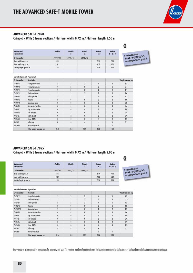
80
THE ADVANCED SAFE-T MOBILE TOWER
Every tower is accompanied by instructions for assembly and use. The required number of additional parts for fastening to the wall or ballasting may be found in the ballasting tables in the catalogue.
ADVANCED SAFE-T 7090 Crimped / With 6 frame sections / Platform width 0.72 m / Platform length 1.50 m
Modules and combinations
Module 1
Module 2
Module3
Module1 + 2
Module1 + 2 + 3
Order number 7090/03 7090/15 7090/17
Reach height approx. m 3.14 5.14 7.14
Tower height approx. m 2.32 4.32 6.32
Standing height approx. m 1.14 3.14 5.14
Individual elements / parts list
Order number Description Weight approx. kg
70794/22 6 rung frame section 2 2 2 4 6 3.2
70094/23 4 rung frame section 0 2 0 2 2 2.1
70894/01 2 rung frame section 2 0 0 2 2 1.1
70894/24 Platform with entry 1 1 1 2 3 7.6
7090/29 Safety guardrail 2 2 2 4 6 3.2
70901/27 Diagonal 2 0 0 2 2 1.0
70894/28 Aluminium brace 2 0 0 2 2 0.8
7070/35 Base section stabiliser 0 4 0 4 4 4.6
7070/37 Exp. section stabiliser 0 0 4 0 4 1.8
70094/25 Side toeboard 0 2 0 2 2 2.4
7072/26 End toeboard 0 2 0 2 2 0.9
7072/50 Castor Ø 125 4 0 0 4 4 1.2
007760 Safety peg 8 8 4 16 20 0.1
0095688 Instruction manual 1 1 1 1 1
Total weight approx. kg 31.8 50.4 28.0 82.2 110.2
Permissible load:
2.0 kN/m2 (200 kg/m2)
according to tower group 3
G
ADVANCED SAFE-T 7095 Crimped / With 8 frame sections / Platform width 0.72 m / Platform length 2.00 m
Modules and combinations
Module1
Module 2
Module 3
Module1 + 2
Module 1 + 2 + 3
Order number 7095/03 7095/15 7095/17
Reach height approx. m 3.14 5.14 7.14
Tower height approx. m 2.32 4.32 6.32
Standing height approx. m 1.14 3.14 5.14
Individual elements / parts list
Order number Description Weight approx. kg
70094/22 8 rung frame section 2 2 2 4 6 4.2
7095/24 Platform with entry 1 1 1 2 3 11.8
7095/29 Safety guardrail 2 2 2 4 6 4.2
70902/27 Diagonal 2 0 0 2 2 1.2
700942/28 Aluminium brace 2 0 0 2 2 1.2
7070/35 Base section stabiliser 0 4 0 4 4 4.6
7070/37 Exp. section stabiliser 0 0 4 0 4 1.8
7071/25 Side toeboard 0 2 0 2 2 3.9
7072/26 End toeboard 0 2 0 2 2 0.9
7072/50 Castor Ø 125 4 0 0 4 4 1.2
007760 Safety peg 4 4 4 8 12 0.1
0095687 Instruction manual 1 1 1 1 1
Total weight approx. kg 38.6 57.0 36.2 95.6 131.8
Permissible load:
2.0 kN/m2 (200 kg/m2)
according to tower group 3
G
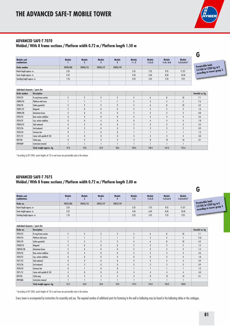
81
Modules and combinations
Module1
Module 2
Module 3
Module 4
Module 1 + 2
Module 1+2+3
Module 1+2+ 3+4
Module 1+2+3+4+4*
Order number 7070/03 7070/15 7070/17 7070/19
Reach height approx. m 3.25 5.25 7.25 9.25 11.25 *
Tower height approx. m 2.47 4.34 6.34 8.34 10.34
Standing height approx. m 1.25 3.25 5.25 7.25 9.25
Individual elements / parts list
Order number Description Gewicht ca. kg
7070/22 8 rung frame section 2 2 2 2 4 6 8 10 7.1
70894/24 Platform with entry 1 1 1 1 2 3 4 5 7.6
7090/29 Safety guardrail 2 2 2 2 4 6 8 10 3.2
70901/27 Diagonal 2 0 0 0 2 2 2 2 1.0
70894/28 Aluminium brace 2 0 0 0 2 2 2 2 0.8
7070/35 Base section stabiliser 0 4 0 0 4 4 4 4 4.6
7070/37 Exp. section stabiliser 0 0 4 0 0 4 4 4 1.8
70094/25 Side toeboard 0 2 0 0 2 2 2 2 2.4
7072/26 End toeboard 0 2 0 0 2 2 2 2 0.9
7070/44 Entrance bar 0 1 0 0 1 1 1 1 1.2
7071/51 Castor with spindle Ø 150 4 0 0 0 4 4 4 4 4.0
007760 Safety peg 0 4 4 4 4 8 12 16 0.1
0095689 Instruction manual 1 1 1 1 1 1 1 1
Total weight approx. kg 47.8 54.8 35.8 28.6 102.6 138.4 167.0 195.6
THE ADVANCED SAFE-T MOBILE TOWER
ADVANCED SAFE-T 7070 Welded / With 8 frame sections / Platform width 0.72 m / Platform length 1.50 m
ADVANCED SAFE-T 7075 Welded / With 8 frame sections / Platform width 0.72 m / Platform length 2.00 m
* According to EN 1004, reach heights of 10 m and more are permissible only in the interior.
Permissible load:
2.0 kN/m2 (200 kg/m2)
according to tower group 3
G
Modules and combinations
Module1
Module2
Module3
Module4
Module1+2
Module1+2+3
Module 1+2+3+4
Module 1+2+3+4+3*
Order no. 7075/03 7075/15 7075/17 7075/19
Reach height approx. m 3.25 5.25 7.25 9.25 11.25 *
Tower height approx. m 2.47 4.34 6.34 8.34 10.34
Standing height approx. m 1.25 3.25 5.25 7.25 9.25
Individual elements / parts list
Order no. Description Gewicht ca. kg
7070/22 8 rung frame section 2 2 2 2 4 6 8 10 7.1
7095/24 Platform with entry 1 1 1 1 2 3 4 5 11.8
7095/29 Safety guardrail 2 2 2 2 4 6 8 10 4.2
70902/27 Diagonal 2 0 0 0 2 2 2 2 1.2
700942/28 Aluminium brace 2 0 0 0 2 2 2 2 1.2
7070/35 Base section stabiliser 0 4 0 0 4 4 4 4 4.6
7070/37 Exp. section stabiliser 0 0 0 4 0 0 4 4 1.8
7071/25 Side toeboard 0 2 0 0 2 2 2 2 3.9
7072/26 End toeboard 0 2 0 0 2 2 2 2 0.9
7070/44 Entrance bar 0 1 0 0 1 1 1 1 1.2
7071/51 Castor with spindle Ø 150 4 0 0 0 4 4 4 4 4.0
007760 Safety peg 0 4 4 4 4 8 12 16 0.1
0095686 Instruction manual 1 1 1 1 1 1 1 1
Total weight approx. kg 55.2 64.0 34.8 42.0 119.2 154.0 196.0 230.8
Permissible load:
2.0 kN/m2 (200 kg/m2)
according to tower group 3
G
Every tower is accompanied by instructions for assembly and use. The required number of additional parts for fastening to the wall or ballasting may be found in the ballasting tables in the catalogue.
* According to EN 1004, reach heights of 10 m and more are permissible only in the interior.
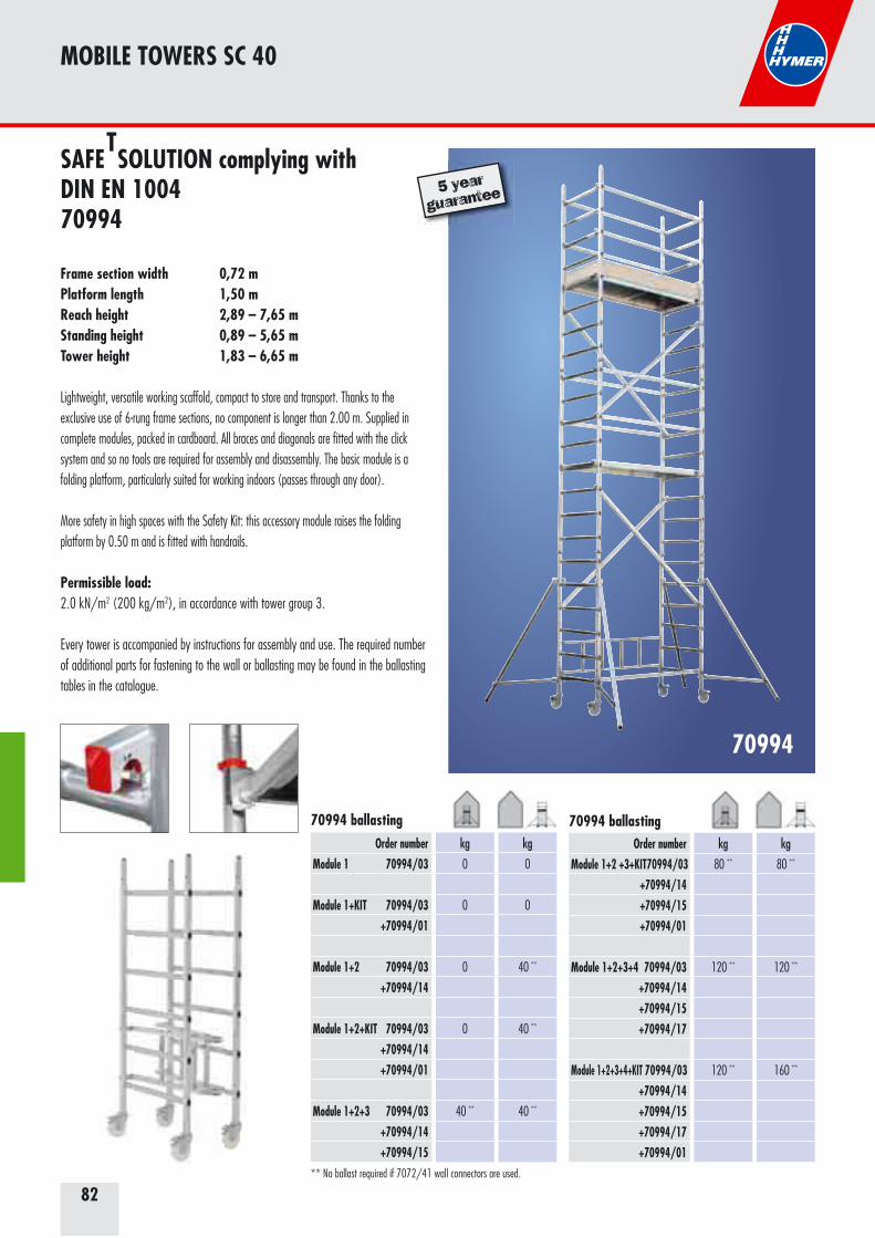
82
MOBILE TOWERS SC 40
SAFE SOLUTION complying with DIN EN 100470994
Frame section width 0,72 mPlatform length 1,50 mReach height 2,89 – 7,65 mStanding height 0,89 – 5,65 mTower height 1,83 – 6,65 m
Lightweight, versatile working scaffold, compact to store and transport. Thanks to the exclusive use of 6-rung frame sections, no component is longer than 2.00 m. Supplied in complete modules, packed in cardboard. All braces and diagonals are fitted with the click system and so no tools are required for assembly and disassembly. The basic module is a folding platform, particularly suited for working indoors (passes through any door).
More safety in high spaces with the Safety Kit: this accessory module raises the folding platform by 0.50 m and is fitted with handrails.
Permissible load: 2.0 kN/m2 (200 kg/m2), in accordance with tower group 3.
Every tower is accompanied by instructions for assembly and use. The required number of additional parts for fastening to the wall or ballasting may be found in the ballasting tables in the catalogue.
T
5 year
guarantee
70994
70994 ballasting
Order numberModule 1+2 +3+KIT 70994/03 +70994/14 +70994/15 +70994/01
Module 1+2+3+4 70994/03 +70994/14 +70994/15 +70994/17
Module 1+2+3+4+KIT 70994/03 +70994/14 +70994/15 +70994/17 +70994/01
kg
80 **
120 **
160 **
70994 ballastingkg
80 **
120 **
120 **
Order numberModule 1 70994/03
Module 1+KIT 70994/03 +70994/01
Module 1+2 70994/03 +70994/14
Module 1+2+KIT 70994/03 +70994/14 +70994/01
Module 1+2+3 70994/03 +70994/14 +70994/15
kg
0
0
40 **
40 **
40 **
kg
0
0
0
0
40 **
** No ballast required if 7072/41 wall connectors are used.
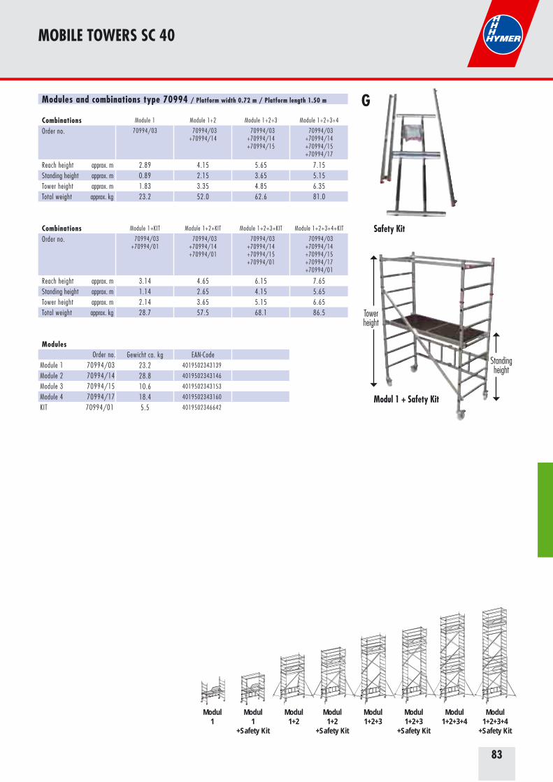
83
GModules and combinations type 70994 / Platform width 0.72 m / Platform length 1.50 m
Combinations Module 1 Module 1+2 Module 1+2+3 Module 1+2+3+4
Order no. 70994/03 70994/03+70994/14
70994/03+70994/14+70994/15
70994/03+70994/14+70994/15+70994/17
Reach height approx. m 2.89 4.15 5.65 7.15Standing height approx. m 0.89 2.15 3.65 5.15Tower height approx. m 1.83 3.35 4.85 6.35Total weight approx. kg 23.2 52.0 62.6 81.0
Combinations Module 1+KIT Module 1+2+KIT Module 1+2+3+KIT Module 1+2+3+4+KIT
Order no. 70994/03 +70994/01
70994/03+70994/14+70994/01
70994/03+70994/14+70994/15+70994/01
70994/03+70994/14+70994/15+70994/17+70994/01
Reach height approx. m 3.14 4.65 6.15 7.65Standing height approx. m 1.14 2.65 4.15 5.65Tower height approx. m 2.14 3.65 5.15 6.65Total weight approx. kg 28.7 57.5 68.1 86.5
Modules Order no. Gewicht ca. kg EAN-CodeModule 1 70994/03 23.2 4019502343139
Module 2 70994/14 28.8 4019502343146
Module 3 70994/15 10.6 4019502343153
Module 4 70994/17 18.4 4019502343160
KIT 70994/01 5.5 4019502346642
MOBILE TOWERS SC 40
Modul 1 + Safety Kit
Towerheight
Standingheight
Safety Kit
Modul Modul Modul Modul Modul Modul Modul Modul1 1 1+2 1+2 1+2+3 1+2+3 1+2+3+4 1+2+3+4
+Safety Kit +Safety Kit +Safety Kit +Safety Kit

84
7074
Mobile tower complying with DIN EN 10047074
Frame section width 0.72 mPlatform length 2.00 mReach height 3.25 – 11.25 mStanding height 1.25 – 9.25 mTower height 2.47 – 10.35 m
Mobile tower in tried-and-tested Hymer modular system. Can be assembled and dismantled without tools easily, quickly and hence economically.With 4 outriggers as standard from reach height of 4.25 m.Outriggers are easy to fit on the frame sections using clamping fittings. Swinging two outriggers to one side allows the wall to be approached closely.Stable castors, 150 mm in diameter with spindle. The spindle sits centrally on the castor and does not project outwards.Precise adjustment to local floor conditions is made possible by height-adjustable castors.Working platforms with non-slip surfaces.Outstanding price/performance ratio makes it very economical.
Permissible load: 2.0 kN/m2 (200 kg/m2), in accordance with tower group 3.
Every tower is accompanied by instructions for assembly and use. The required number of additional parts for fastening to the wall or ballasting may be found in the ballasting tables in the catalogue.
MOBILE TOWERS SC 40
5 year
guarantee
Order no.7074/03 7074/04 7074/057074/06 7074/07 7074/087074/09 7074/10 7074/11
kg
0
50 **
80 **
110 **
140 **
180 **
220 **
260 **
300 **
kg
0
0
0
0
0
40 **
100 **
not permitted
not permitted
kg
0
50 **
90 **
130 **
180 **
250 **
0 2)
not permitted
not permitted
kg
0
0
0
0
0
40 **
40 **
60 **
80 **
7074 ballasting
** No ballast required if 7072/41 wall connectors are used.Required additional parts2) plus 2 wall connectors, order no. 7072/41
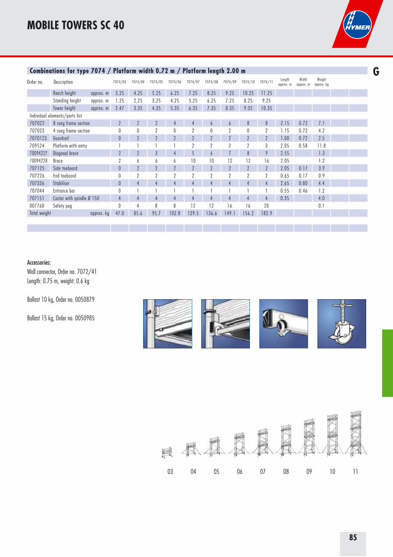
85
MOBILE TOWERS SC 40
Accessories: Wall connector, Order no. 7072/41Length: 0.75 m, weight: 0.6 kg
Ballast 10 kg, Order no. 0050879
Ballast 15 kg, Order no. 0050985
GCombinations for type 7074 / Platform width 0.72 m / Platform length 2.00 m
Order no. Description 7074/03 7074/04 7074/05 7074/06 7074/07 7074/08 7074/09 7074/10 7074/11Length
approx. mWidth
approx. mWeight
approx. kg
Reach height approx. m 3.25 4.25 5.25 6.25 7.25 8.25 9.25 10.25 11.25Standing height approx. m 1.25 2.25 3.25 4.25 5.25 6.25 7.25 8.25 9.25Tower height approx. m 2.47 3.35 4.35 5.35 6.35 7.35 8.35 9.35 10.35
Individual elements/parts list707022 8 rung frame section 2 2 2 4 4 6 6 8 8 2.15 0.72 7.1707023 4 rung frame section 0 0 2 0 2 0 2 0 2 1.15 0.72 4.27070123 Guardrail 0 2 2 2 2 2 2 2 2 1.00 0.72 2.5709524 Platform with entry 1 1 1 1 2 2 2 2 3 2.05 0.58 11.870094227 Diagonal brace 2 2 3 4 5 6 7 8 9 2.55 1.370094228 Brace 2 6 6 6 10 10 12 12 16 2.05 1.2707125 Side toeboard 0 2 2 2 2 2 2 2 2 2.05 0.17 3.9707226 End toeboard 0 2 2 2 2 2 2 2 2 0.65 0.17 0.9707336 Stabiliser 0 4 4 4 4 4 4 4 4 2.65 0.80 4.4707044 Entrance bar 0 1 1 1 1 1 1 1 1 0.55 0.46 1.2707151 Castor with spindle Ø 150 4 4 4 4 4 4 4 4 4 0.35 4.0007760 Safety peg 0 4 8 8 12 12 16 16 20 0.1Total weight approx. kg 47.0 85.6 95.7 102.8 129.5 136.6 149.1 156.2 182.9
04 06 07 08 09 10 110503

86
MOBILE TOWERS SC 60
6071
Example of use on stairs.
5 year
guarantee
03 06 08 09 10 11 12 1304 0705
Order no.6371/036371/046371/056371/066371/076371/086371/096371/106371/116371/126371/13
kg
0
20 *
60 *
80 *
100 *
120 *
140 *
160 *
200 *
220 *
240 *
kg
0
0
0
0
0
0
0
not permitted
not permitted
not permitted
not permitted
kg
0
40 *
80 *
120 *
160 1) *
0 1)
0 1)
not permitted
not permitted
not permitted
not permitted
6371ballasting
6071ballasting
* No ballast required if 6071/41 wall connectors are used.Required additional parts1) plus 2 wall connectors, order no. 6071/413) plus 2 stabiliser bar extensions, order no. 6072/344) plus 1 long side stabiliser bar, order no. 6071/43
Order no.6071/046071/056071/066071/076071/086071/096071/106071/116071/126071/13
kg
0
20 *
40 4) *
60 4) *
80 4) *
60 4) *
80 4) *
100 4) *
100 4) *
120 4) *
kg
0
0
0 3)
0 3)
80 3)
120
not permitted
not permitted
not permitted
not permitted
kg
0
20 3) *
40 3) 4) *
80 3) 4) *
120 3) 4) *
160 4) *
nicht zulässig
not permitted
not permitted
not permitted
6371
Mobile tower complying with DIN EN 10046371/6071
Frame section width 0.80 mPlatform length 2.95 mReach height 3.40 – 13.40 m / 4.60 – 13.60 mStanding height 1.40 – 11.40 m / 2.60 – 11.60 mTower height 2.40 – 12.40 m / 3.60 – 12.60 m
Safe to assemble and dismantle thanks to the use of one stage per level. Scaffold sections can easily be passed from one level to the next.
Permissible load: 3.0 kN (300 kg) distributed load, corresponds to 2.0 kN/m2 (200 kg/m2) according to tower group 3, EN 1004.
Every tower is accompanied by instructions for assembly and use. The required number of additional parts for fastening to the wall or ballasting may be found in the ballasting tables in the catalogue.
Required additional elements: Ballast 10 kg, order no. 0050879 Ballast 15 kg, order no. 0050985 Wall connector, order no. 6071/41 Longitudinal stabiliser bar, order no. 6071/43 Stabiliser, order no. 6371/36
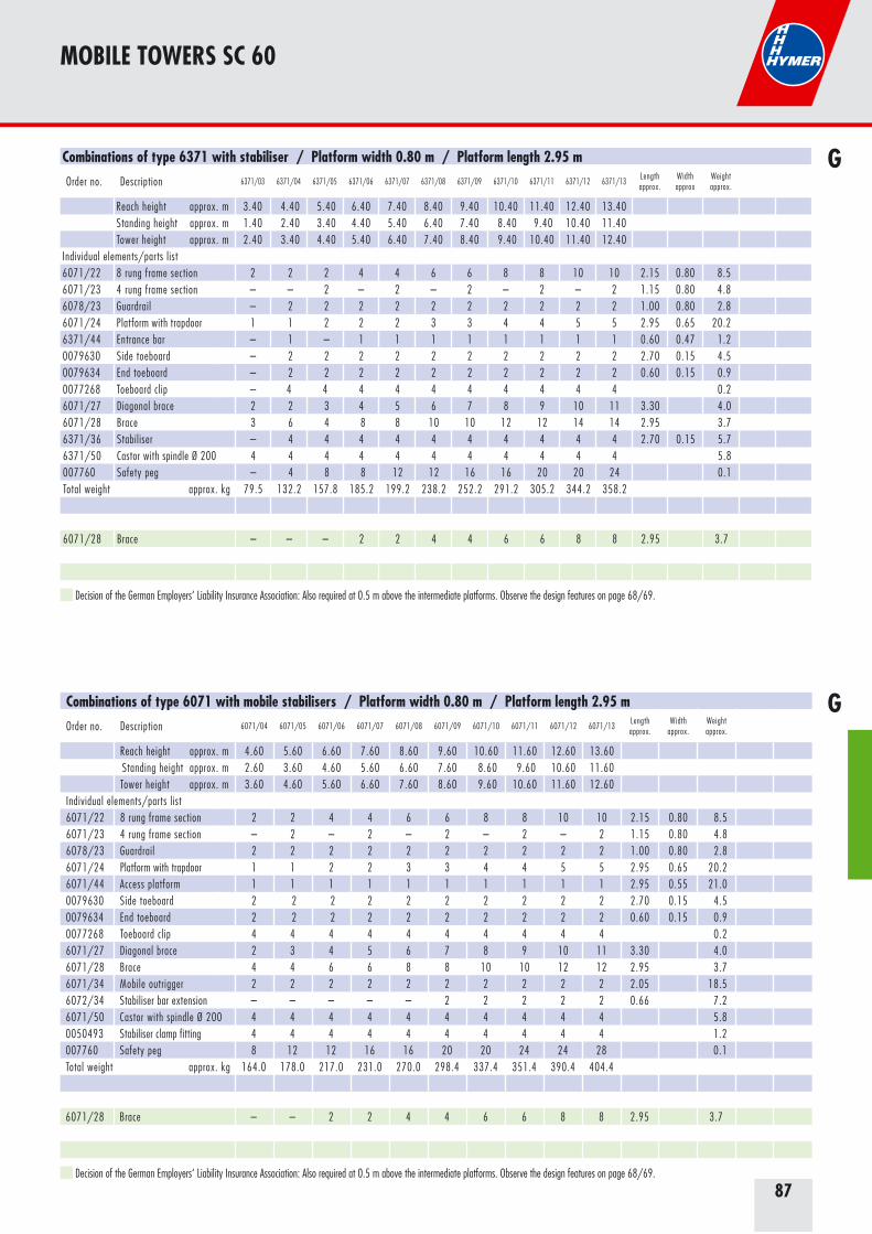
87
MOBILE TOWERS SC 60
Combinations of type 6371 with stabiliser / Platform width 0.80 m / Platform length 2.95 m
Order no. Description 6371/03 6371/04 6371/05 6371/06 6371/07 6371/08 6371/09 6371/10 6371/11 6371/12 6371/13Lengthapprox.
Widthapprox
Weightapprox.
Reach height approx. m 3.40 4.40 5.40 6.40 7.40 8.40 9.40 10.40 11.40 12.40 13.40Standing height approx. m 1.40 2.40 3.40 4.40 5.40 6.40 7.40 8.40 9.40 10.40 11.40Tower height approx. m 2.40 3.40 4.40 5.40 6.40 7.40 8.40 9.40 10.40 11.40 12.40
Individual elements/parts list 6071/22 8 rung frame section 2 2 2 4 4 6 6 8 8 10 10 2.15 0.80 8.56071/23 4 rung frame section – – 2 – 2 – 2 – 2 – 2 1.15 0.80 4.86078/23 Guardrail – 2 2 2 2 2 2 2 2 2 2 1.00 0.80 2.86071/24 Plat form with trapdoor 1 1 2 2 2 3 3 4 4 5 5 2.95 0.65 20.26371/44 Entrance bar – 1 – 1 1 1 1 1 1 1 1 0.60 0.47 1.20079630 Side toeboard – 2 2 2 2 2 2 2 2 2 2 2.70 0.15 4.50079634 End toeboard – 2 2 2 2 2 2 2 2 2 2 0.60 0.15 0.90077268 Toeboard clip – 4 4 4 4 4 4 4 4 4 4 0.26071/27 Diagonal brace 2 2 3 4 5 6 7 8 9 10 11 3.30 4.06071/28 Brace 3 6 4 8 8 10 10 12 12 14 14 2.95 3.76371/36 Stabiliser – 4 4 4 4 4 4 4 4 4 4 2.70 0.15 5.76371/50 Castor with spindle Ø 200 4 4 4 4 4 4 4 4 4 4 4 5.8007760 Safety peg – 4 8 8 12 12 16 16 20 20 24 0.1Total weight approx. kg 79.5 132.2 157.8 185.2 199.2 238.2 252.2 291.2 305.2 344.2 358.2
6071/28 Brace – – – 2 2 4 4 6 6 8 8 2.95 3.7
Combinations of type 6071 with mobile stabilisers / Platform width 0.80 m / Platform length 2.95 m
Order no. Description 6071/04 6071/05 6071/06 6071/07 6071/08 6071/09 6071/10 6071/11 6071/12 6071/13Lengthapprox.
Widthapprox.
Weightapprox.
Reach height approx. m 4.60 5.60 6.60 7.60 8.60 9.60 10.60 11.60 12.60 13.60Standing height approx. m 2.60 3.60 4.60 5.60 6.60 7.60 8.60 9.60 10.60 11.60Tower height approx. m 3.60 4.60 5.60 6.60 7.60 8.60 9.60 10.60 11.60 12.60
Individual elements/parts list6071/22 8 rung frame section 2 2 4 4 6 6 8 8 10 10 2.15 0.80 8.56071/23 4 rung frame section – 2 – 2 – 2 – 2 – 2 1.15 0.80 4.86078/23 Guardrail 2 2 2 2 2 2 2 2 2 2 1.00 0.80 2.86071/24 Platform with trapdoor 1 1 2 2 3 3 4 4 5 5 2.95 0.65 20.26071/44 Access platform 1 1 1 1 1 1 1 1 1 1 2.95 0.55 21.00079630 Side toeboard 2 2 2 2 2 2 2 2 2 2 2.70 0.15 4.50079634 End toeboard 2 2 2 2 2 2 2 2 2 2 0.60 0.15 0.90077268 Toeboard clip 4 4 4 4 4 4 4 4 4 4 0.26071/27 Diagonal brace 2 3 4 5 6 7 8 9 10 11 3.30 4.06071/28 Brace 4 4 6 6 8 8 10 10 12 12 2.95 3.76071/34 Mobile outrigger 2 2 2 2 2 2 2 2 2 2 2.05 18.56072/34 Stabiliser bar extension – – – – – 2 2 2 2 2 0.66 7.26071/50 Castor with spindle Ø 200 4 4 4 4 4 4 4 4 4 4 5.80050493 Stabiliser clamp fitting 4 4 4 4 4 4 4 4 4 4 1.2007760 Safety peg 8 12 12 16 16 20 20 24 24 28 0.1Total weight approx. kg 164.0 178.0 217.0 231.0 270.0 298.4 337.4 351.4 390.4 404.4
6071/28 Brace – – 2 2 4 4 6 6 8 8 2.95 3.7
G
G
Decision of the German Employers‘ Liability Insurance Association: Also required at 0.5 m above the intermediate platforms. Observe the design features on page 68/69.
Decision of the German Employers‘ Liability Insurance Association: Also required at 0.5 m above the intermediate platforms. Observe the design features on page 68/69.
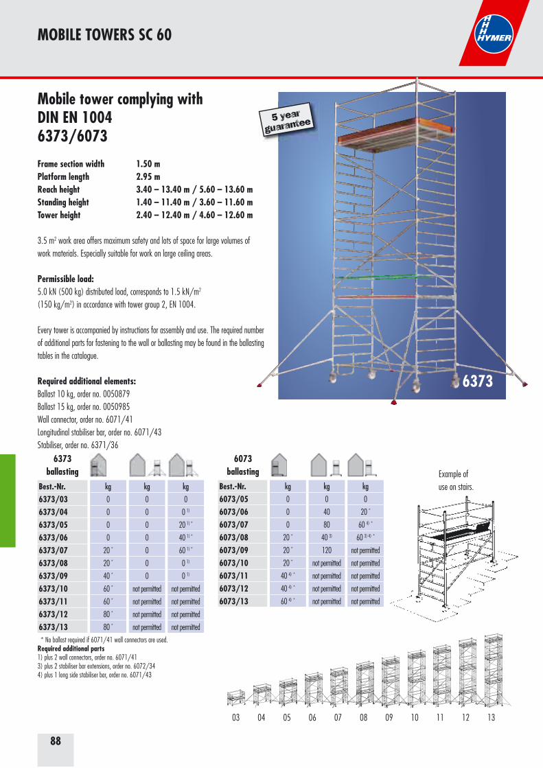
88
Mobile tower complying with DIN EN 10046373/6073
Frame section width 1.50 mPlatform length 2.95 mReach height 3.40 – 13.40 m / 5.60 – 13.60 mStanding height 1.40 – 11.40 m / 3.60 – 11.60 mTower height 2.40 – 12.40 m / 4.60 – 12.60 m
3.5 m2 work area offers maximum safety and lots of space for large volumes of work materials. Especially suitable for work on large ceiling areas.
Permissible load: 5.0 kN (500 kg) distributed load, corresponds to 1.5 kN/m2
(150 kg/m2) in accordance with tower group 2, EN 1004.
Every tower is accompanied by instructions for assembly and use. The required number of additional parts for fastening to the wall or ballasting may be found in the ballasting tables in the catalogue.
Required additional elements: Ballast 10 kg, order no. 0050879 Ballast 15 kg, order no. 0050985 Wall connector, order no. 6071/41 Longitudinal stabiliser bar, order no. 6071/43 Stabiliser, order no. 6371/36
MOBILE TOWERS SC 60
Example of use on stairs.
5 year
guarantee
03 06 08 09 10 11 12 1304 0705
Best.-Nr.6373/036373/046373/056373/066373/076373/086373/096373/106373/116373/126373/13
kg
0
0
0
0
20 *
20 *
40 *
60 *
60 *
80 *
80 *
kg
0
0
0
0
0
0
0
not permitted
not permitted
not permitted
not permitted
kg
0
0 1)
20 1) *
40 1) *
60 1) *
0 1)
0 1)
not permitted
not permitted
not permitted
not permitted
* No ballast required if 6071/41 wall connectors are used.Required additional parts1) plus 2 wall connectors, order no. 6071/413) plus 2 stabiliser bar extensions, order no. 6072/344) plus 1 long side stabiliser bar, order no. 6071/43
Best.-Nr.6073/056073/066073/076073/086073/096073/106073/116073/126073/13
kg
0
0
0
20 *
20 *
20 *
40 4) *
40 4) *
60 4) *
kg
0
40
80
40 3)
120
not permitted
not permitted
not permitted
not permitted
kg
0
20 *
60 4) *
60 3) 4) *
not permitted
not permitted
not permitted
not permitted
not permitted
6373
6373ballasting
6073ballasting
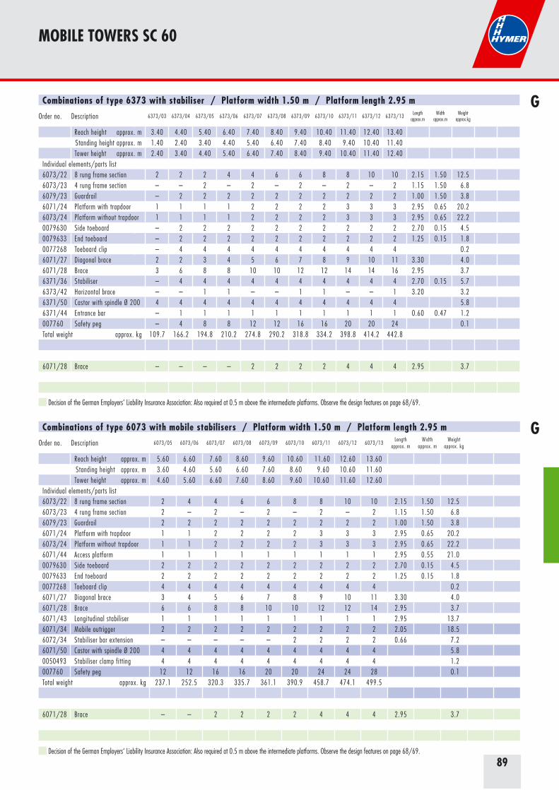
89
Combinations of type 6373 with stabiliser / Platform width 1.50 m / Platform length 2.95 m
Order no. Description 6373/03 6373/04 6373/05 6373/06 6373/07 6373/08 6373/09 6373/10 6373/11 6373/12 6373/13 Lengthapprox.m
Widthapprox.m
Weightapprox.kg
Reach height approx. m 3.40 4.40 5.40 6.40 7.40 8.40 9.40 10.40 11.40 12.40 13.40Standing height approx. m 1.40 2.40 3.40 4.40 5.40 6.40 7.40 8.40 9.40 10.40 11.40Tower height approx. m 2.40 3.40 4.40 5.40 6.40 7.40 8.40 9.40 10.40 11.40 12.40
Individual elements/parts list6073/22 8 rung frame section 2 2 2 4 4 6 6 8 8 10 10 2.15 1.50 12.56073/23 4 rung frame section – – 2 – 2 – 2 – 2 – 2 1.15 1.50 6.86079/23 Guardrail – 2 2 2 2 2 2 2 2 2 2 1.00 1.50 3.86071/24 Platform with trapdoor 1 1 1 1 2 2 2 2 3 3 3 2.95 0.65 20.26073/24 Platform without trapdoor 1 1 1 1 2 2 2 2 3 3 3 2.95 0.65 22.20079630 Side toeboard – 2 2 2 2 2 2 2 2 2 2 2.70 0.15 4.50079633 End toeboard – 2 2 2 2 2 2 2 2 2 2 1.25 0.15 1.80077268 Toeboard clip – 4 4 4 4 4 4 4 4 4 4 0.26071/27 Diagonal brace 2 2 3 4 5 6 7 8 9 10 11 3.30 4.06071/28 Brace 3 6 8 8 10 10 12 12 14 14 16 2.95 3.76371/36 Stabiliser – 4 4 4 4 4 4 4 4 4 4 2.70 0.15 5.76373/42 Horizontal brace – – 1 1 – – 1 1 – – 1 3.20 3.26371/50 Castor with spindle Ø 200 4 4 4 4 4 4 4 4 4 4 4 5.86371/44 Entrance bar – 1 1 1 1 1 1 1 1 1 1 0.60 0.47 1.2007760 Safety peg – 4 8 8 12 12 16 16 20 20 24 0.1Total weight approx. kg 109.7 166.2 194.8 210.2 274.8 290.2 318.8 334.2 398.8 414.2 442.8
6071/28 Brace – – – – 2 2 2 2 4 4 4 2.95 3.7
Combinations of type 6073 with mobile stabilisers / Platform width 1.50 m / Platform length 2.95 m
Order no. Description 6073/05 6073/06 6073/07 6073/08 6073/09 6073/10 6073/11 6073/12 6073/13Length
approx. mWidth
approx. mWeight
approx. kg
Reach height approx. m 5.60 6.60 7.60 8.60 9.60 10.60 11.60 12.60 13.60Standing height approx. m 3.60 4.60 5.60 6.60 7.60 8.60 9.60 10.60 11.60Tower height approx. m 4.60 5.60 6.60 7.60 8.60 9.60 10.60 11.60 12.60
Individual elements/parts list6073/22 8 rung frame section 2 4 4 6 6 8 8 10 10 2.15 1.50 12.56073/23 4 rung frame section 2 – 2 – 2 – 2 – 2 1.15 1.50 6.86079/23 Guardrail 2 2 2 2 2 2 2 2 2 1.00 1.50 3.86071/24 Platform with trapdoor 1 1 2 2 2 2 3 3 3 2.95 0.65 20.26073/24 Platform without trapdoor 1 1 2 2 2 2 3 3 3 2.95 0.65 22.26071/44 Access platform 1 1 1 1 1 1 1 1 1 2.95 0.55 21.00079630 Side toeboard 2 2 2 2 2 2 2 2 2 2.70 0.15 4.50079633 End toeboard 2 2 2 2 2 2 2 2 2 1.25 0.15 1.80077268 Toeboard clip 4 4 4 4 4 4 4 4 4 0.26071/27 Diagonal brace 3 4 5 6 7 8 9 10 11 3.30 4.06071/28 Brace 6 6 8 8 10 10 12 12 14 2.95 3.76071/43 Longitudinal stabiliser 1 1 1 1 1 1 1 1 1 2.95 13.76071/34 Mobile outrigger 2 2 2 2 2 2 2 2 2 2.05 18.56072/34 Stabiliser bar extension – – – – – 2 2 2 2 0.66 7.26071/50 Castor with spindle Ø 200 4 4 4 4 4 4 4 4 4 5.80050493 Stabiliser clamp fitting 4 4 4 4 4 4 4 4 4 1.2007760 Safety peg 12 12 16 16 20 20 24 24 28 0.1Total weight approx. kg 237.1 252.5 320.3 335.7 361.1 390.9 458.7 474.1 499.5
6071/28 Brace – – 2 2 2 2 4 4 4 2.95 3.7
MOBILE TOWERS SC 60
G
G
Decision of the German Employers‘ Liability Insurance Association: Also required at 0.5 m above the intermediate platforms. Observe the design features on page 68/69.
Decision of the German Employers‘ Liability Insurance Association: Also required at 0.5 m above the intermediate platforms. Observe the design features on page 68/69.
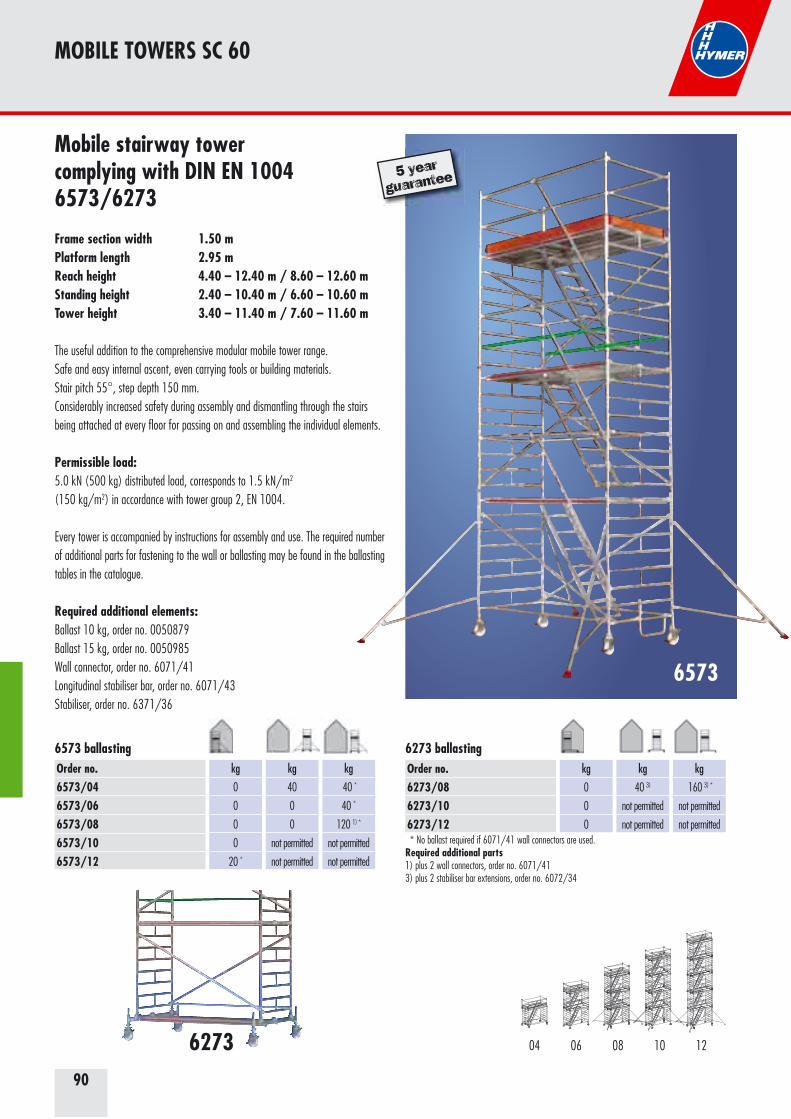
90
Mobile stairway tower complying with DIN EN 10046573/6273
Frame section width 1.50 mPlatform length 2.95 mReach height 4.40 – 12.40 m / 8.60 – 12.60 m Standing height 2.40 – 10.40 m / 6.60 – 10.60 mTower height 3.40 – 11.40 m / 7.60 – 11.60 m
The useful addition to the comprehensive modular mobile tower range.Safe and easy internal ascent, even carrying tools or building materials.Stair pitch 55°, step depth 150 mm.Considerably increased safety during assembly and dismantling through the stairs being attached at every floor for passing on and assembling the individual elements.
Permissible load: 5.0 kN (500 kg) distributed load, corresponds to 1.5 kN/m2
(150 kg/m2) in accordance with tower group 2, EN 1004.
Every tower is accompanied by instructions for assembly and use. The required number of additional parts for fastening to the wall or ballasting may be found in the ballasting tables in the catalogue.
Required additional elements: Ballast 10 kg, order no. 0050879 Ballast 15 kg, order no. 0050985 Wall connector, order no. 6071/41 Longitudinal stabiliser bar, order no. 6071/43 Stabiliser, order no. 6371/36
6573
MOBILE TOWERS SC 60
6273
5 year
guarantee
* No ballast required if 6071/41 wall connectors are used.Required additional parts1) plus 2 wall connectors, order no. 6071/413) plus 2 stabiliser bar extensions, order no. 6072/34
Order no.6573/046573/066573/086573/106573/12
kg
0
0
0
0
20 *
kg
40
0
0
not permitted
not permitted
kg
40 *
40 *
120 1) *
not permitted
not permitted
6573 ballastingOrder no.6273/086273/106273/12
kg
0
0
0
kg
40 3)
not permitted
not permitted
kg
160 3) *
not permitted
not permitted
6273 ballasting
06 08 1004 12
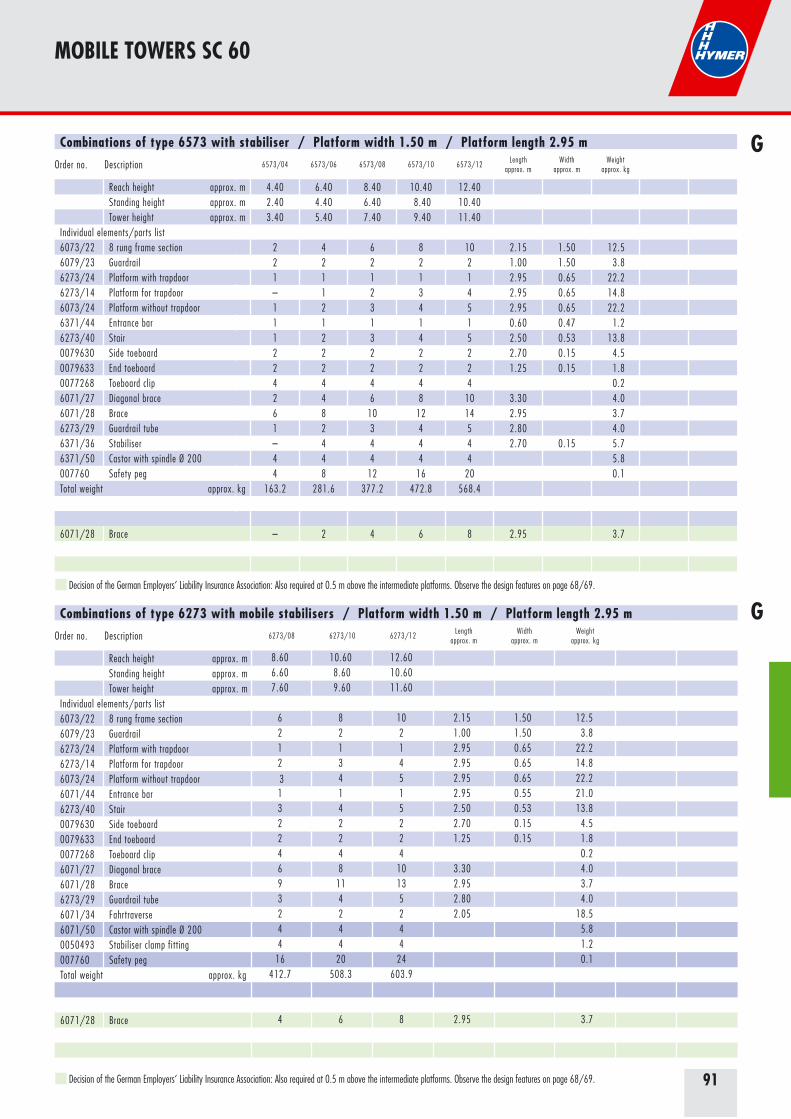
91
Combinations of type 6573 with stabiliser / Platform width 1.50 m / Platform length 2.95 m
Order no. Description 6573/04 6573/06 6573/08 6573/10 6573/12Length
approx. mWidth
approx. mWeight
approx. kg
Reach height approx. m 4.40 6.40 8.40 10.40 12.40Standing height approx. m 2.40 4.40 6.40 8.40 10.40Tower height approx. m 3.40 5.40 7.40 9.40 11.40
Individual elements/parts list6073/22 8 rung frame section 2 4 6 8 10 2.15 1.50 12.56079/23 Guardrail 2 2 2 2 2 1.00 1.50 3.86273/24 Platform with trapdoor 1 1 1 1 1 2.95 0.65 22.26273/14 Platform for trapdoor – 1 2 3 4 2.95 0.65 14.86073/24 Platform without trapdoor 1 2 3 4 5 2.95 0.65 22.26371/44 Entrance bar 1 1 1 1 1 0.60 0.47 1.26273/40 Stair 1 2 3 4 5 2.50 0.53 13.80079630 Side toeboard 2 2 2 2 2 2.70 0.15 4.50079633 End toeboard 2 2 2 2 2 1.25 0.15 1.80077268 Toeboard clip 4 4 4 4 4 0.26071/27 Diagonal brace 2 4 6 8 10 3.30 4.06071/28 Brace 6 8 10 12 14 2.95 3.76273/29 Guardrail tube 1 2 3 4 5 2.80 4.06371/36 Stabiliser – 4 4 4 4 2.70 0.15 5.76371/50 Castor with spindle Ø 200 4 4 4 4 4 5.8007760 Safety peg 4 8 12 16 20 0.1Total weight approx. kg 163.2 281.6 377.2 472.8 568.4
6071/28 Brace – 2 4 6 8 2.95 3.7
Combinations of type 6273 with mobile stabilisers / Platform width 1.50 m / Platform length 2.95 m
Order no. Description 6273/08 6273/10 6273/12Length
approx. mWidth
approx. mWeight
approx. kg
Reach height approx. m 8.60 10.60 12.60
Standing height approx. m 6.60 8.60 10.60
Tower height approx. m 7.60 9.60 11.60
Individual elements/parts list6073/22 8 rung frame section 6 8 10 2.15 1.50 12.5
6079/23 Guardrail 2 2 2 1.00 1.50 3.8
6273/24 Platform with trapdoor 1 1 1 2.95 0.65 22.2
6273/14 Platform for trapdoor 2 3 4 2.95 0.65 14.8
6073/24 Platform without trapdoor 3 4 5 2.95 0.65 22.2
6071/44 Entrance bar 1 1 1 2.95 0.55 21.0
6273/40 Stair 3 4 5 2.50 0.53 13.8
0079630 Side toeboard 2 2 2 2.70 0.15 4.5
0079633 End toeboard 2 2 2 1.25 0.15 1.8
0077268 Toeboard clip 4 4 4 0.2
6071/27 Diagonal brace 6 8 10 3.30 4.0
6071/28 Brace 9 11 13 2.95 3.7
6273/29 Guardrail tube 3 4 5 2.80 4.0
6071/34 Fahrtraverse 2 2 2 2.05 18.5
6071/50 Castor with spindle Ø 200 4 4 4 5.8
0050493 Stabiliser clamp fitting 4 4 4 1.2
007760 Safety peg 16 20 24 0.1
Total weight approx. kg 412.7 508.3 603.9
6071/28 Brace 4 6 8 2.95 3.7
MOBILE TOWERS SC 60
G
G
Decision of the German Employers‘ Liability Insurance Association: Also required at 0.5 m above the intermediate platforms. Observe the design features on page 68/69.
Decision of the German Employers‘ Liability Insurance Association: Also required at 0.5 m above the intermediate platforms. Observe the design features on page 68/69.
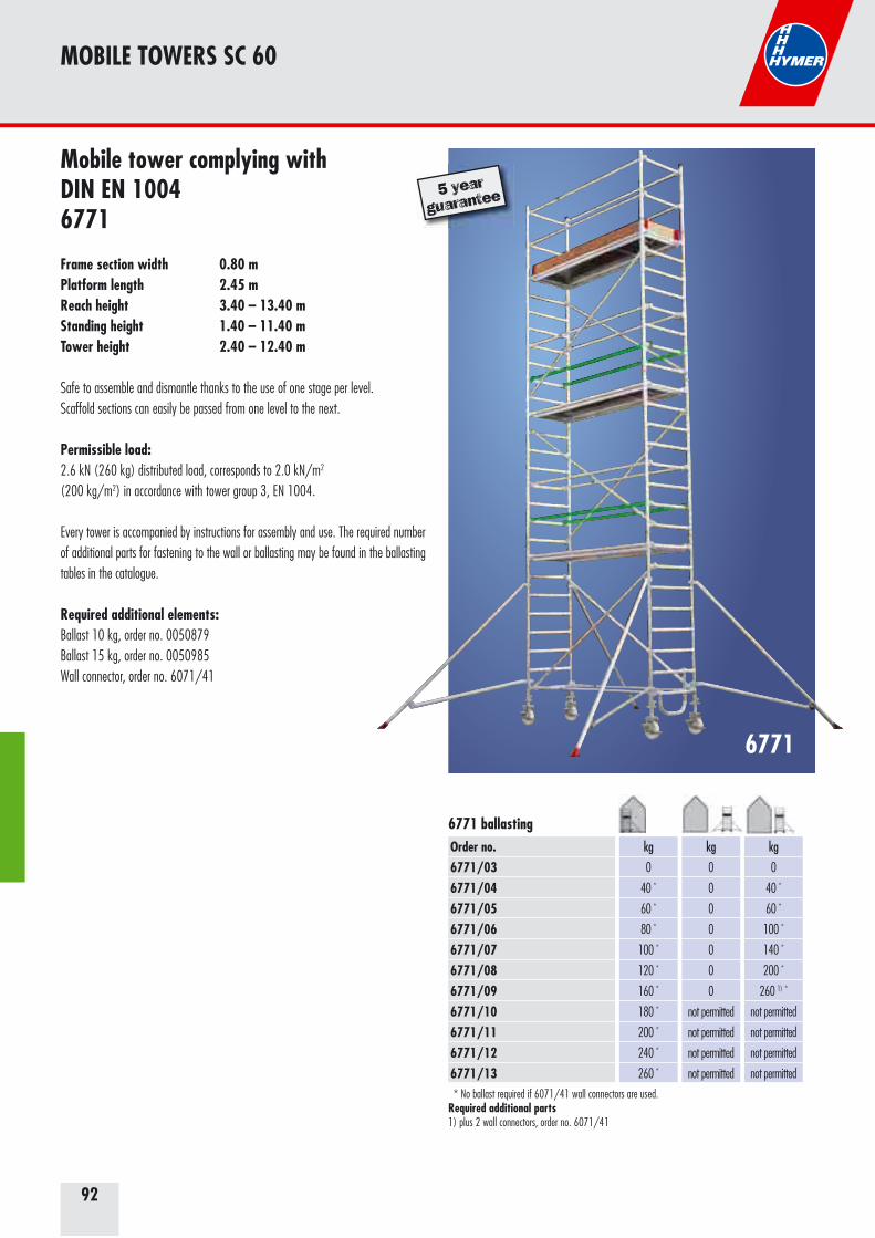
92
Mobile tower complying with DIN EN 10046771
Frame section width 0.80 mPlatform length 2.45 mReach height 3.40 – 13.40 mStanding height 1.40 – 11.40 m Tower height 2.40 – 12.40 m
Safe to assemble and dismantle thanks to the use of one stage per level. Scaffold sections can easily be passed from one level to the next.
Permissible load: 2.6 kN (260 kg) distributed load, corresponds to 2.0 kN/m2 (200 kg/m2) in accordance with tower group 3, EN 1004.
Every tower is accompanied by instructions for assembly and use. The required number of additional parts for fastening to the wall or ballasting may be found in the ballasting tables in the catalogue.
Required additional elements: Ballast 10 kg, order no. 0050879 Ballast 15 kg, order no. 0050985 Wall connector, order no. 6071/41
6771
MOBILE TOWERS SC 60
5 year
guarantee
Order no.6771/036771/046771/056771/066771/076771/086771/096771/106771/116771/126771/13
kg
0
40 *
60 *
80 *
100 *
120 *
160 *
180 *
200 *
240 *
260 *
kg
0
0
0
0
0
0
0
not permitted
not permitted
not permitted
not permitted
kg
0
40 *
60 *
100 *
140 *
200 *
260 1) *
not permitted
not permitted
not permitted
not permitted
* No ballast required if 6071/41 wall connectors are used.Required additional parts1) plus 2 wall connectors, order no. 6071/41
6771 ballasting

93
Combinations of type 6771 with stabiliser / Platform width 0.80 m / Platform length 2.45 m
Order no. Description 6771/03 6771/04 6771/05 6771/06 6771/07 6771/08 6771/09 6771/10 6771/11 6771/12 6771/13Length
approx. mWidth
approx. mWeight
approx. kg
Reach height approx. m 3.40 4.40 5.40 6.40 7.40 8.40 9.40 10.40 11.40 12.40 13.40Standing height approx. m 1.40 2.40 3.40 4.40 5.40 6.40 7.40 8.40 9.40 10.40 11.40Tower height approx. m 2.40 3.40 4.40 5.40 6.40 7.40 8.40 9.40 10.40 11.40 12.40
Individual elements/parts list6071/22 8 rung frame section 2 2 2 4 4 6 6 8 8 10 10 2.15 0.80 8.56071/23 4 rung frame section – – 2 – 2 – 2 – 2 – 2 1.15 0.80 4.86078/23 Guardrail – 2 2 2 2 2 2 2 2 2 2 1.00 0.80 2.86771/24 Platform with trapdoor 1 1 2 2 2 3 3 4 4 5 5 2.40 0.65 16.56371/44 Entrance bar – 1 – 1 1 1 1 1 1 1 1 0.60 0.47 1.20079631 Side toeboard – 2 2 2 2 2 2 2 2 2 2 2.20 0.15 3.50079634 End toeboard – 2 2 2 2 2 2 2 2 2 2 0.60 0.15 0.90077268 Toeboard clip – 4 4 4 4 4 4 4 4 4 4 0.26771/27 Diagonal brace 2 2 3 4 5 6 7 8 9 10 11 2.90 3.36378/27 Brace 3 6 4 8 8 10 10 12 12 14 14 2.45 2.56371/36 Stabiliser – 4 4 4 4 4 4 4 4 4 4 2.70 0.15 5.76371/50 Castor with spindle Ø 200 4 4 4 4 4 4 4 4 4 4 4 5.8007760 Safety peg – 4 8 8 12 12 16 16 20 20 24 0.1Total weight approx. kg 70.8 117.9 141.5 163.4 176.7 208.9 222.2 254.4 267.7 299.9 313.2
6378/27 Brace – – – 2 2 4 4 6 6 8 8 2.45 2.5
MOBILE TOWERS SC 60
G
Example of use on stairs.
Decision of the German Employers‘ Liability Insurance Association: Also required at 0.5 m above the intermediate platforms. Observe the design features on page 68/69.
03 06 08 09 10 11 12 1304 0705
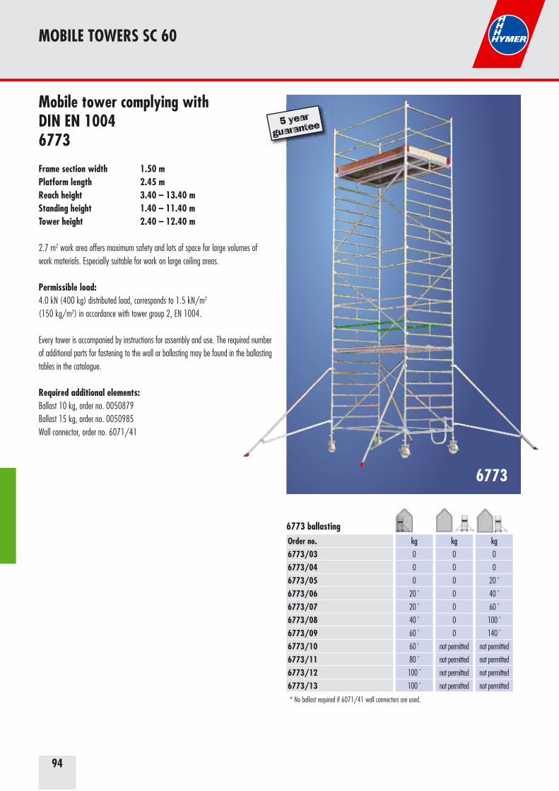
94
Mobile tower complying with DIN EN 10046773
Frame section width 1.50 mPlatform length 2.45 mReach height 3.40 – 13.40 mStanding height 1.40 – 11.40 m Tower height 2.40 – 12.40 m
2.7 m2 work area offers maximum safety and lots of space for large volumes ofwork materials. Especially suitable for work on large ceiling areas.
Permissible load: 4.0 kN (400 kg) distributed load, corresponds to 1.5 kN/m2
(150 kg/m2) in accordance with tower group 2, EN 1004.
Every tower is accompanied by instructions for assembly and use. The required number of additional parts for fastening to the wall or ballasting may be found in the ballasting tables in the catalogue.
Required additional elements: Ballast 10 kg, order no. 0050879 Ballast 15 kg, order no. 0050985 Wall connector, order no. 6071/41
6773
MOBILE TOWERS SC 60
5 year
guarantee
Order no.6773/036773/046773/056773/066773/076773/086773/096773/106773/116773/126773/13
kg
0
0
0
20 *
20 *
40 *
60 *
60 *
80 *
100 *
100 *
kg
0
0
0
0
0
0
0
not permitted
not permitted
not permitted
not permitted
kg
0
0
20 *
40 *
60 *
100 *
140 *
not permitted
not permitted
not permitted
not permitted
6773 ballasting
* No ballast required if 6071/41 wall connectors are used.
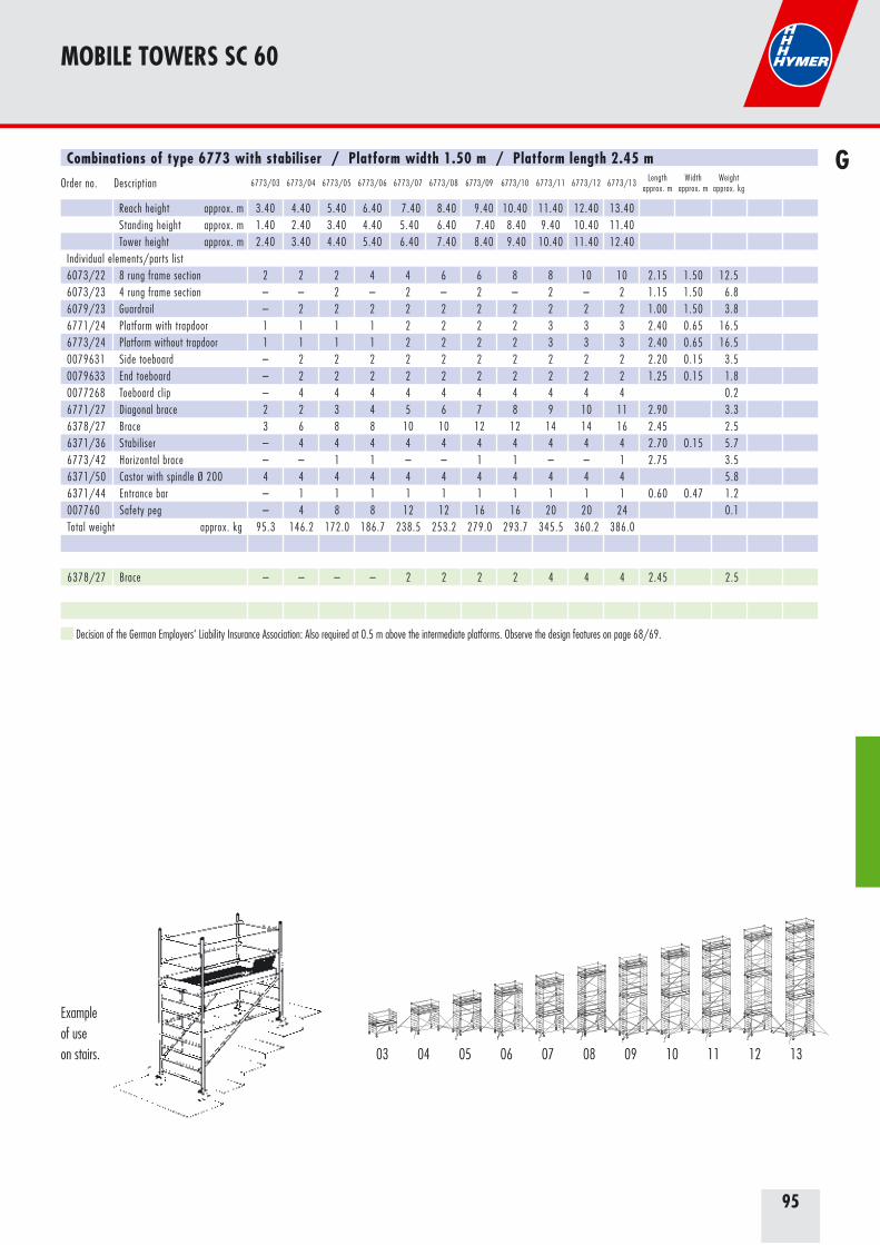
95
Combinations of type 6773 with stabiliser / Platform width 1.50 m / Platform length 2.45 m
Order no. Description 6773/03 6773/04 6773/05 6773/06 6773/07 6773/08 6773/09 6773/10 6773/11 6773/12 6773/13Length
approx. mWidth
approx. mWeight
approx. kg
Reach height approx. m 3.40 4.40 5.40 6.40 7.40 8.40 9.40 10.40 11.40 12.40 13.40Standing height approx. m 1.40 2.40 3.40 4.40 5.40 6.40 7.40 8.40 9.40 10.40 11.40Tower height approx. m 2.40 3.40 4.40 5.40 6.40 7.40 8.40 9.40 10.40 11.40 12.40
Individual elements/parts list6073/22 8 rung frame section 2 2 2 4 4 6 6 8 8 10 10 2.15 1.50 12.56073/23 4 rung frame section – – 2 – 2 – 2 – 2 – 2 1.15 1.50 6.86079/23 Guardrail – 2 2 2 2 2 2 2 2 2 2 1.00 1.50 3.86771/24 Platform with trapdoor 1 1 1 1 2 2 2 2 3 3 3 2.40 0.65 16.56773/24 Platform without trapdoor 1 1 1 1 2 2 2 2 3 3 3 2.40 0.65 16.50079631 Side toeboard – 2 2 2 2 2 2 2 2 2 2 2.20 0.15 3.50079633 End toeboard – 2 2 2 2 2 2 2 2 2 2 1.25 0.15 1.80077268 Toeboard clip – 4 4 4 4 4 4 4 4 4 4 0.26771/27 Diagonal brace 2 2 3 4 5 6 7 8 9 10 11 2.90 3.36378/27 Brace 3 6 8 8 10 10 12 12 14 14 16 2.45 2.56371/36 Stabiliser – 4 4 4 4 4 4 4 4 4 4 2.70 0.15 5.76773/42 Horizontal brace – – 1 1 – – 1 1 – – 1 2.75 3.56371/50 Castor with spindle Ø 200 4 4 4 4 4 4 4 4 4 4 4 5.86371/44 Entrance bar – 1 1 1 1 1 1 1 1 1 1 0.60 0.47 1.2007760 Safety peg – 4 8 8 12 12 16 16 20 20 24 0.1Total weight approx. kg 95.3 146.2 172.0 186.7 238.5 253.2 279.0 293.7 345.5 360.2 386.0
6378/27 Brace – – – – 2 2 2 2 4 4 4 2.45 2.5
MOBILE TOWERS SC 60
G
Example of useon stairs.
Decision of the German Employers‘ Liability Insurance Association: Also required at 0.5 m above the intermediate platforms. Observe the design features on page 68/69.
03 06 08 09 10 11 12 1304 0705
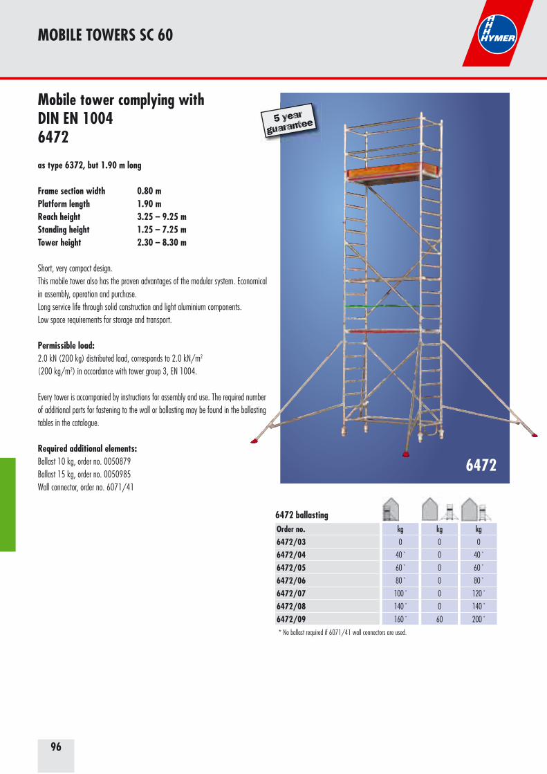
96
Mobile tower complying with DIN EN 10046472
as type 6372, but 1.90 m long
Frame section width 0.80 mPlatform length 1.90 mReach height 3.25 – 9.25 mStanding height 1.25 – 7.25 m Tower height 2.30 – 8.30 m
Short, very compact design.This mobile tower also has the proven advantages of the modular system. Economical in assembly, operation and purchase.Long service life through solid construction and light aluminium components.Low space requirements for storage and transport.
Permissible load:2.0 kN (200 kg) distributed load, corresponds to 2.0 kN/m2 (200 kg/m2) in accordance with tower group 3, EN 1004.
Every tower is accompanied by instructions for assembly and use. The required number of additional parts for fastening to the wall or ballasting may be found in the ballasting tables in the catalogue.
Required additional elements: Ballast 10 kg, order no. 0050879 Ballast 15 kg, order no. 0050985 Wall connector, order no. 6071/41
6472
MOBILE TOWERS SC 60
5 year
guarantee
Order no.6472/036472/046472/056472/066472/076472/086472/09
kg
0
40 *
60 *
80 *
100 *
140 *
160 *
kg
0
0
0
0
0
0
60
kg
0
40 *
60 *
80 *
120 *
140 *
200 *
6472 ballasting
* No ballast required if 6071/41 wall connectors are used.
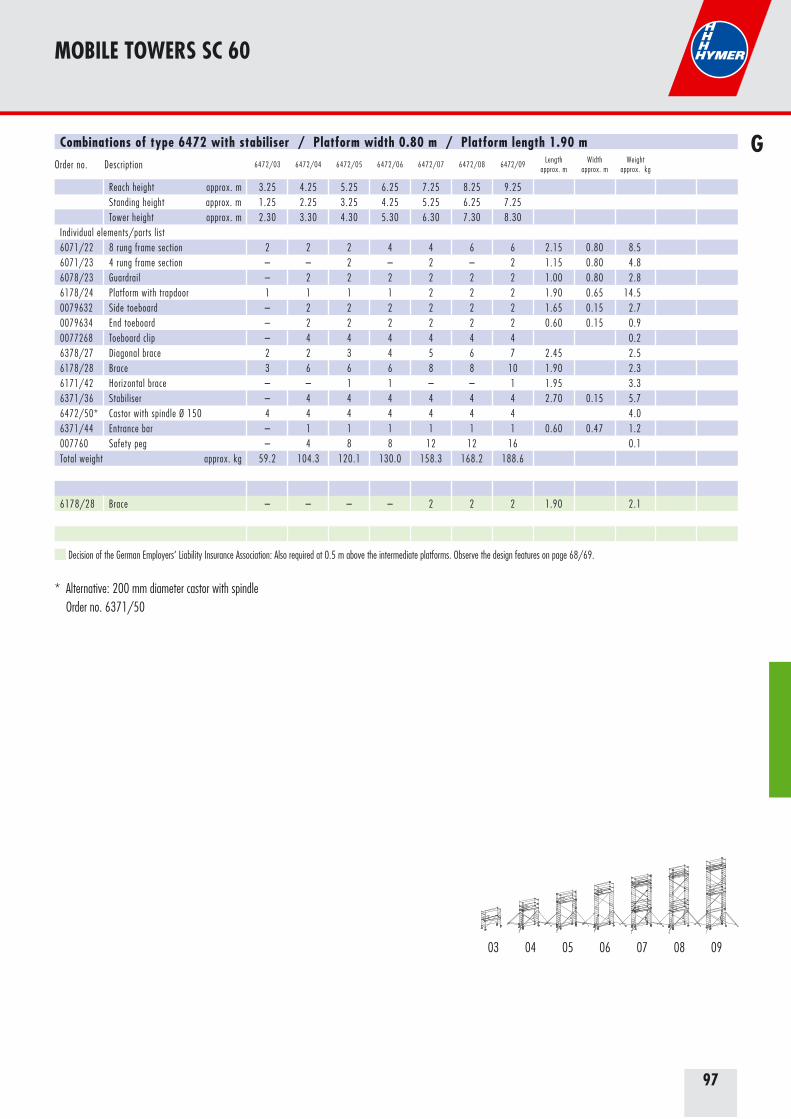
97
Combinations of type 6472 with stabiliser / Platform width 0.80 m / Platform length 1.90 m
Order no. Description 6472/03 6472/04 6472/05 6472/06 6472/07 6472/08 6472/09Length
approx. mWidth
approx. mWeight
approx. kg
Reach height approx. m 3.25 4.25 5.25 6.25 7.25 8.25 9.25Standing height approx. m 1.25 2.25 3.25 4.25 5.25 6.25 7.25Tower height approx. m 2.30 3.30 4.30 5.30 6.30 7.30 8.30
Individual elements/parts list6071/22 8 rung frame section 2 2 2 4 4 6 6 2.15 0.80 8.56071/23 4 rung frame section – – 2 – 2 – 2 1.15 0.80 4.86078/23 Guardrail – 2 2 2 2 2 2 1.00 0.80 2.86178/24 Platform with trapdoor 1 1 1 1 2 2 2 1.90 0.65 14.50079632 Side toeboard – 2 2 2 2 2 2 1.65 0.15 2.70079634 End toeboard – 2 2 2 2 2 2 0.60 0.15 0.90077268 Toeboard clip – 4 4 4 4 4 4 0.26378/27 Diagonal brace 2 2 3 4 5 6 7 2.45 2.56178/28 Brace 3 6 6 6 8 8 10 1.90 2.36171/42 Horizontal brace – – 1 1 – – 1 1.95 3.36371/36 Stabiliser – 4 4 4 4 4 4 2.70 0.15 5.76472/50* Castor with spindle Ø 150 4 4 4 4 4 4 4 4.06371/44 Entrance bar – 1 1 1 1 1 1 0.60 0.47 1.2007760 Safety peg – 4 8 8 12 12 16 0.1Total weight approx. kg 59.2 104.3 120.1 130.0 158.3 168.2 188.6
6178/28 Brace – – – – 2 2 2 1.90 2.1
* Alternative: 200 mm diameter castor with spindle Order no. 6371/50
MOBILE TOWERS SC 60
G
Decision of the German Employers‘ Liability Insurance Association: Also required at 0.5 m above the intermediate platforms. Observe the design features on page 68/69.
03 06 08 0904 0705
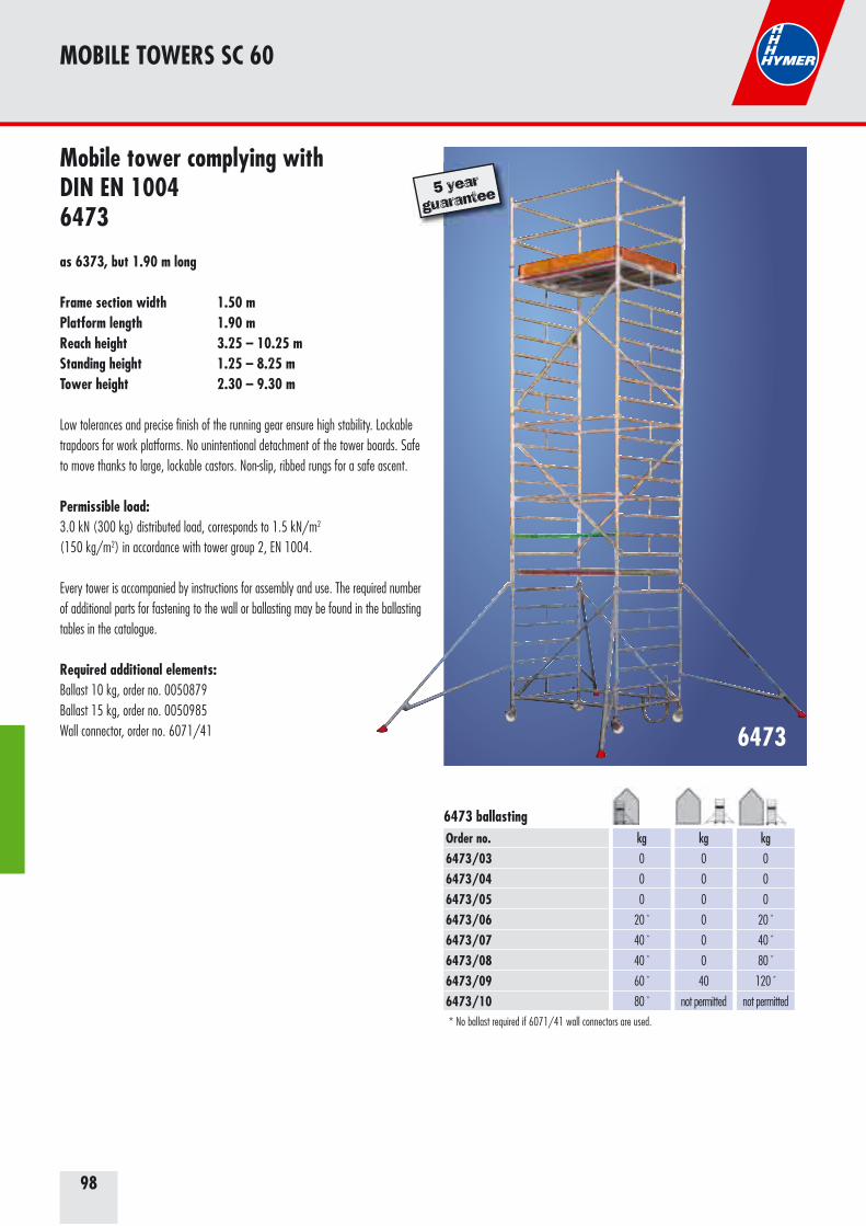
98
Mobile tower complying with DIN EN 10046473
as 6373, but 1.90 m long
Frame section width 1.50 mPlatform length 1.90 mReach height 3.25 – 10.25 mStanding height 1.25 – 8.25 m Tower height 2.30 – 9.30 m
Low tolerances and precise finish of the running gear ensure high stability. Lockable trapdoors for work platforms. No unintentional detachment of the tower boards. Safe to move thanks to large, lockable castors. Non-slip, ribbed rungs for a safe ascent.
Permissible load: 3.0 kN (300 kg) distributed load, corresponds to 1.5 kN/m2 (150 kg/m2) in accordance with tower group 2, EN 1004.
Every tower is accompanied by instructions for assembly and use. The required number of additional parts for fastening to the wall or ballasting may be found in the ballasting tables in the catalogue.
Required additional elements: Ballast 10 kg, order no. 0050879 Ballast 15 kg, order no. 0050985 Wall connector, order no. 6071/41 6473
MOBILE TOWERS SC 60
5 year
guarantee
Order no.6473/036473/046473/056473/066473/076473/086473/096473/10
kg
0
0
0
20 *
40 *
40 *
60 *
80 *
kg
0
0
0
0
0
0
40
not permitted
kg
0
0
0
20 *
40 *
80 *
120 *
not permitted
6473 ballasting
* No ballast required if 6071/41 wall connectors are used.
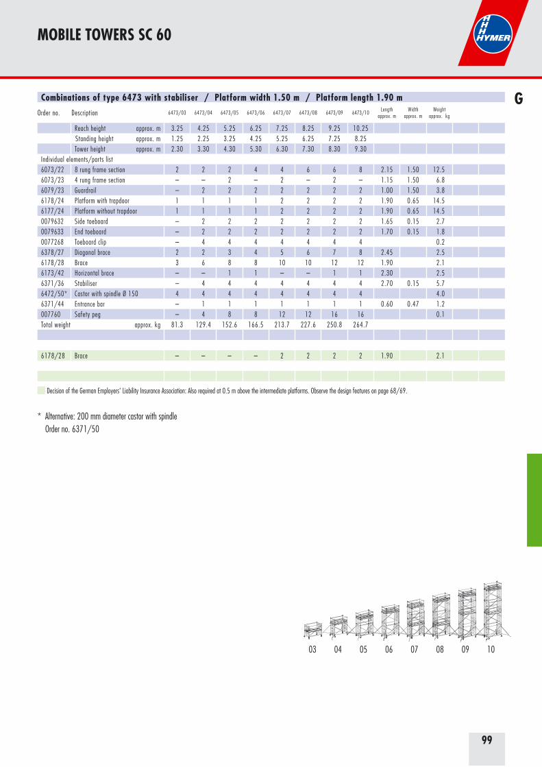
99
Combinations of type 6473 with stabiliser / Platform width 1.50 m / Platform length 1.90 m
Order no. Description 6473/03 6473/04 6473/05 6473/06 6473/07 6473/08 6473/09 6473/10Length
approx. mWidth
approx. mWeight
approx. kg
Reach height approx. m 3.25 4.25 5.25 6.25 7.25 8.25 9.25 10.25Standing height approx. m 1.25 2.25 3.25 4.25 5.25 6.25 7.25 8.25Tower height approx. m 2.30 3.30 4.30 5.30 6.30 7.30 8.30 9.30
Individual elements/parts list6073/22 8 rung frame section 2 2 2 4 4 6 6 8 2.15 1.50 12.56073/23 4 rung frame section – – 2 – 2 – 2 – 1.15 1.50 6.86079/23 Guardrail – 2 2 2 2 2 2 2 1.00 1.50 3.86178/24 Platform with trapdoor 1 1 1 1 2 2 2 2 1.90 0.65 14.56177/24 Platform without trapdoor 1 1 1 1 2 2 2 2 1.90 0.65 14.50079632 Side toeboard – 2 2 2 2 2 2 2 1.65 0.15 2.70079633 End toeboard – 2 2 2 2 2 2 2 1.70 0.15 1.80077268 Toeboard clip – 4 4 4 4 4 4 4 0.26378/27 Diagonal brace 2 2 3 4 5 6 7 8 2.45 2.56178/28 Brace 3 6 8 8 10 10 12 12 1.90 2.16173/42 Horizontal brace – – 1 1 – – 1 1 2.30 2.56371/36 Stabiliser – 4 4 4 4 4 4 4 2.70 0.15 5.76472/50* Castor with spindle Ø 150 4 4 4 4 4 4 4 4 4.06371/44 Entrance bar – 1 1 1 1 1 1 1 0.60 0.47 1.2007760 Safety peg – 4 8 8 12 12 16 16 0.1Total weight approx. kg 81.3 129.4 152.6 166.5 213.7 227.6 250.8 264.7
6178/28 Brace – – – – 2 2 2 2 1.90 2.1
* Alternative: 200 mm diameter castor with spindle Order no. 6371/50
MOBILE TOWERS SC 60
G
Decision of the German Employers‘ Liability Insurance Association: Also required at 0.5 m above the intermediate platforms. Observe the design features on page 68/69.
03 06 08 09 1004 0705

100
Mobile stairway tower complying with DIN EN 10046576
as 6573, but 1.90 m long
Frame section width 1.50 mPlatform length 1.90 mReach height 4.25 – 14.25 mStanding height 2.25 – 12.25 m Tower height 3.30 – 13.30 m
This mobile tower also has the proven advantages of the modular system. Economical in assembly, operation and purchase.Short, very compact design.Long service life through solid construction and light aluminium components.
Permissible load: 3.0 kN (300 kg) distributed load, corresponds to 1.5 kN/m2 (150 kg/m2) in accordance with tower group 2, EN 1004.
Every tower is accompanied by instructions for assembly and use. The required number of additional parts for fastening to the wall or ballasting may be found in the ballasting tables in the catalogue.
Required additional elements: Ballast 10 kg, order no. 0050879 Ballast 15 kg, order no. 0050985 Wall connector, order no. 6071/41
6576
MOBILE TOWERS SC 60
5 year
guarantee
Best.-Nr.6576/046576/066576/086576/106576/126576/14
kg
0
0
20 *
40 *
60 *
100 *
kg
0
0
40
not permitted
not permitted
not permitted
kg
0
20 *
100 *
not permitted
not permitted
not permitted
6576 ballasting
* No ballast required if 6071/41 wall connectors are used.
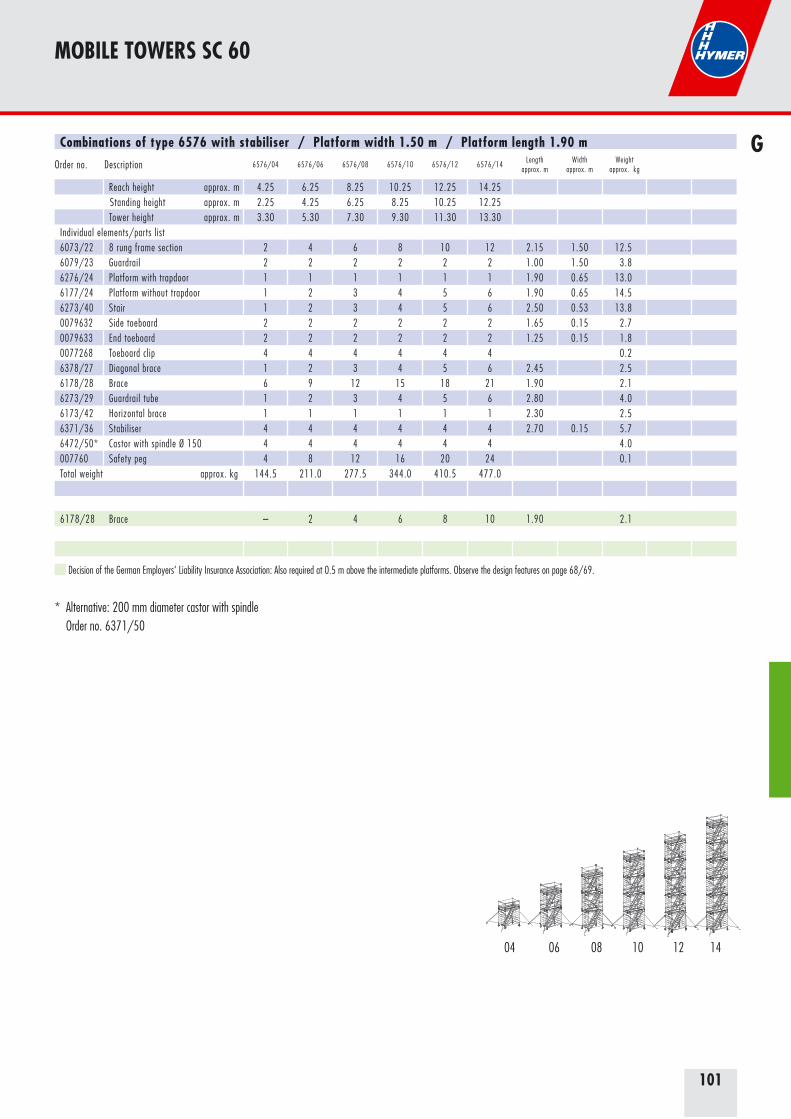
101
Combinations of type 6576 with stabiliser / Platform width 1.50 m / Platform length 1.90 m
Order no. Description 6576/04 6576/06 6576/08 6576/10 6576/12 6576/14Length
approx. mWidth
approx. mWeight
approx. kg
Reach height approx. m 4.25 6.25 8.25 10.25 12.25 14.25Standing height approx. m 2.25 4.25 6.25 8.25 10.25 12.25Tower height approx. m 3.30 5.30 7.30 9.30 11.30 13.30
Individual elements/parts list6073/22 8 rung frame section 2 4 6 8 10 12 2.15 1.50 12.56079/23 Guardrail 2 2 2 2 2 2 1.00 1.50 3.86276/24 Platform with trapdoor 1 1 1 1 1 1 1.90 0.65 13.06177/24 Platform without trapdoor 1 2 3 4 5 6 1.90 0.65 14.56273/40 Stair 1 2 3 4 5 6 2.50 0.53 13.80079632 Side toeboard 2 2 2 2 2 2 1.65 0.15 2.70079633 End toeboard 2 2 2 2 2 2 1.25 0.15 1.80077268 Toeboard clip 4 4 4 4 4 4 0.26378/27 Diagonal brace 1 2 3 4 5 6 2.45 2.56178/28 Brace 6 9 12 15 18 21 1.90 2.16273/29 Guardrail tube 1 2 3 4 5 6 2.80 4.06173/42 Horizontal brace 1 1 1 1 1 1 2.30 2.56371/36 Stabiliser 4 4 4 4 4 4 2.70 0.15 5.76472/50* Castor with spindle Ø 150 4 4 4 4 4 4 4.0007760 Safety peg 4 8 12 16 20 24 0.1Total weight approx. kg 144.5 211.0 277.5 344.0 410.5 477.0
6178/28 Brace – 2 4 6 8 10 1.90 2.1
* Alternative: 200 mm diameter castor with spindle Order no. 6371/50
MOBILE TOWERS SC 60
G
Decision of the German Employers‘ Liability Insurance Association: Also required at 0.5 m above the intermediate platforms. Observe the design features on page 68/69.
06 08 10 12 1404
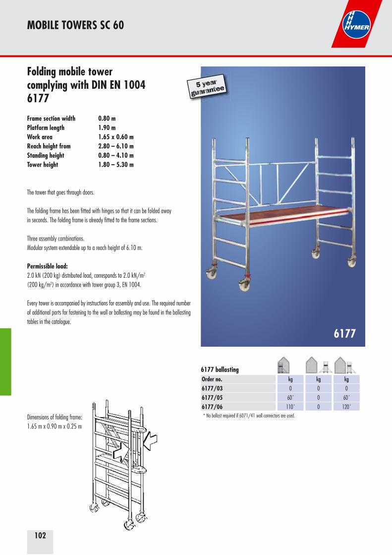
102
Folding mobile tower complying with DIN EN 10046177
Frame section width 0.80 mPlatform length 1.90 mWork area 1.65 x 0.60 mReach height from 2.80 – 6.10 mStanding height 0.80 – 4.10 mTower height 1.80 – 5.30 m
The tower that goes through doors.
The folding frame has been fitted with hinges so that it can be folded awayin seconds. The folding frame is already fitted to the frame sections.
Three assembly combinations.Modular system extendable up to a reach height of 6.10 m.
Permissible load: 2.0 kN (200 kg) distributed load, corresponds to 2.0 kN/m2 (200 kg/m2) in accordance with tower group 3, EN 1004.
Every tower is accompanied by instructions for assembly and use. The required number of additional parts for fastening to the wall or ballasting may be found in the ballasting tables in the catalogue.
6177
Dimensions of folding frame:1.65 m x 0.90 m x 0.25 m
MOBILE TOWERS SC 60
5 year
guarantee
Order no. 6177/036177/056177/06
kg
0
60 *
110 *
kg
0
0
0
kg
0
60 *
120 *
6177 ballasting
* No ballast required if 6071/41 wall connectors are used.
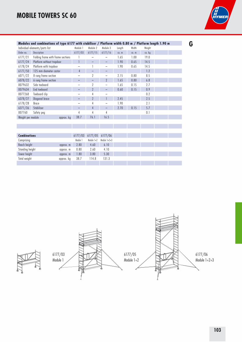
103
Modules and combinations of type 6177 with stabiliser / Platform width 0.80 m / Platform length 1.90 m Individual elements/parts list Module 1 Module 2 Module 3 Length Width Weight
Order no. Description 6177/03 6177/15 6177/16 ca. m ca. m ca. kg
6177/21 Folding frame with frame sections 1 – – 1.65 1.00 19.06177/24 Platform without trapdoor 1 – – 1.90 0.65 14.56178/24 Platform with trapdoor – 1 – 1.90 0.65 14.56177/50 125 mm diameter castor 4 – – 1.26071/22 8 rung frame section – 2 – 2.15 0.80 8.56078/22 6 rung frame section – – 2 1.65 0.80 6.80079632 Side toeboard – 2 – 1.65 0.15 2.70079634 End toeboard – 2 – 0.60 0.15 0.90077268 Toeboard clip – 4 – 0.26378/27 Diagonal brace – 2 1 2.45 2.56178/28 Brace – 4 – 1.90 2.16371/36 Stabiliser – 4 – 2.70 0.15 5.7007760 Safety peg 4 4 4 0.1
Weight per module approx. kg 38.7 76.1 16.5
Combinations 6177/03 6177/05 6177/06Comprising Module 1 Module 1+2 Module 1+2+3
Reach height approx. m 2.80 4.60 6.10Standing height approx. m 0.80 2.60 4.10Tower height approx. m 1.80 3.80 5.30Total weight approx. kg 38.7 114.8 131.3
MOBILE TOWERS SC 60
G
6177/03Module 1
6177/05Module 1+2
6177/06Module 1+2+3
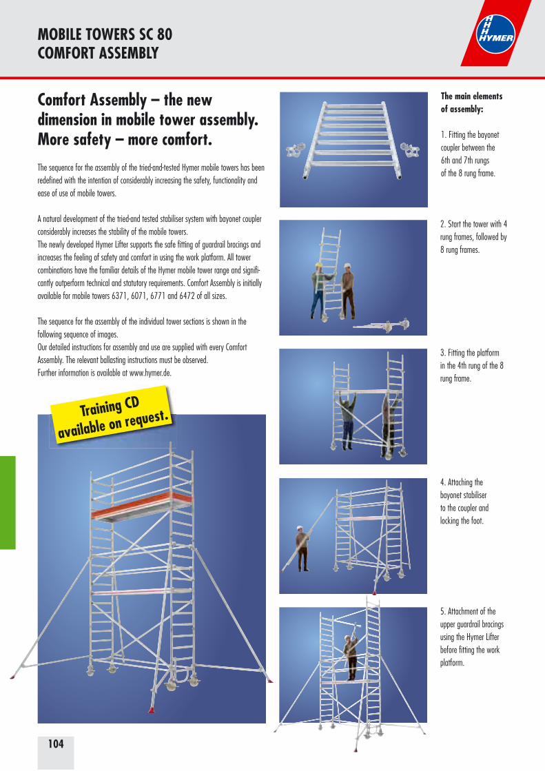
104
MOBILE TOWERS SC 80COMFORT ASSEMBLY
Comfort Assembly – the new dimension in mobile tower assembly.More safety – more comfort.The sequence for the assembly of the tried-and-tested Hymer mobile towers has been redefined with the intention of considerably increasing the safety, functionality and ease of use of mobile towers.
A natural development of the tried-and tested stabiliser system with bayonet coupler considerably increases the stability of the mobile towers.The newly developed Hymer Lifter supports the safe fitting of guardrail bracings and increases the feeling of safety and comfort in using the work platform. All tower combinations have the familiar details of the Hymer mobile tower range and signifi-cantly outperform technical and statutory requirements. Comfort Assembly is initially available for mobile towers 6371, 6071, 6771 and 6472 of all sizes.
The sequence for the assembly of the individual tower sections is shown in the following sequence of images.Our detailed instructions for assembly and use are supplied with every Comfort Assembly. The relevant ballasting instructions must be observed.Further information is available at www.hymer.de.
Training CD
available on request.
The main elementsof assembly:
1. Fitting the bayonetcoupler between the6th and 7th rungsof the 8 rung frame.
4. Attaching thebayonet stabiliserto the coupler andlocking the foot.
3. Fitting the platform in the 4th rung of the 8 rung frame.
2. Start the tower with 4 rung frames, followed by 8 rung frames.
5. Attachment of the upper guardrail bracings using the Hymer Lifter before fitting the work platform.
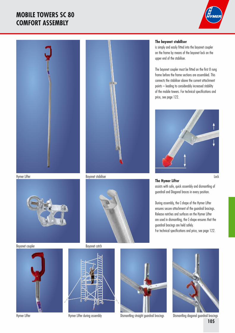
105
MOBILE TOWERS SC 80COMFORT ASSEMBLY
The bayonet stabiliseris simply and easily fitted into the bayonet coupleron the frame by means of the bayonet lock on the upper end of the stabiliser.
The bayonet coupler must be fitted on the first 8 rung frame before the frame sections are assembled. This connects the stabiliser above the current attachment points – leading to considerably increased stability of the mobile towers. For technical specifications and price, see page 122.
The Hymer Lifterassists with safe, quick assembly and dismantling of guardrail and Diagonal braces in every position.
During assembly, the C-shape of the Hymer Lifter ensures secure attachment of the guardrail bracings. Release notches and surfaces on the Hymer Lifter are used in dismantling, the C-shape ensures that the guardrail bracings are held safely.For technical specifications and price, see page 122.
Hymer Lifter Hymer Lifter during assembly Dismantling straight guardrail bracings Dismantling diagonal guardrail bracings
Bayonet coupler Bayonet catch
LockHymer Lifter Bayonet stabiliser
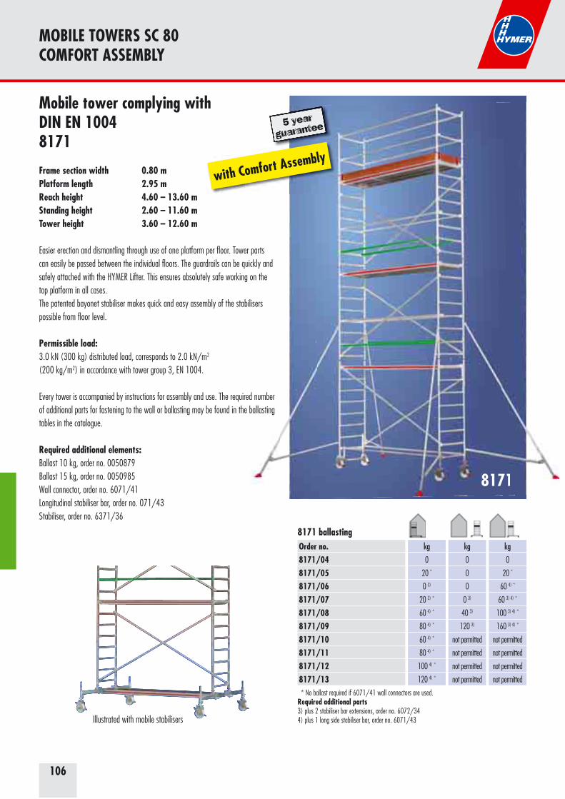
106
8171
5 year
guarantee
MOBILE TOWERS SC 80COMFORT ASSEMBLY
8171
5 year
guarantee
Mobile tower complying with DIN EN 10048171
Frame section width 0.80 mPlatform length 2.95 mReach height 4.60 – 13.60 mStanding height 2.60 – 11.60 mTower height 3.60 – 12.60 m
Easier erection and dismantling through use of one platform per floor. Tower parts can easily be passed between the individual floors. The guardrails can be quickly and safely attached with the HYMER Lifter. This ensures absolutely safe working on the top platform in all cases.The patented bayonet stabiliser makes quick and easy assembly of the stabilisers possible from floor level.
Permissible load: 3.0 kN (300 kg) distributed load, corresponds to 2.0 kN/m2 (200 kg/m2) in accordance with tower group 3, EN 1004.
Every tower is accompanied by instructions for assembly and use. The required number of additional parts for fastening to the wall or ballasting may be found in the ballasting tables in the catalogue.
Required additional elements: Ballast 10 kg, order no. 0050879 Ballast 15 kg, order no. 0050985 Wall connector, order no. 6071/41 Longitudinal stabiliser bar, order no. 071/43 Stabiliser, order no. 6371/36
Illustrated with mobile stabilisers
with Comfort Assembly
Order no.8171/048171/058171/068171/078171/088171/098171/108171/118171/128171/13
kg
0
20 *
0 3)
20 3) *
60 4) *
80 4) *
60 4) *
80 4) *
100 4) *
120 4) *
kg
0
0
0
0 3)
40 3)
120 3)
not permitted
not permitted
not permitted
not permitted
kg
0
20 *
60 4) *
60 3) 4) *
100 3) 4) *
160 3) 4) *
not permitted
not permitted
not permitted
not permitted
* No ballast required if 6071/41 wall connectors are used.Required additional parts3) plus 2 stabiliser bar extensions, order no. 6072/344) plus 1 long side stabiliser bar, order no. 6071/43
8171 ballasting

107
G
MOBILE TOWERS SC 80COMFORT ASSEMBLY
Example of use on stairs.
Combinations of type 8171 with mobile outrigger / Platform width 0.80 m / Platform length 2.95 m
Order no. Description 8171/04 8171/05 8171/06 8171/07 8171/08 8171/09 8171/10 8171/11 8171/12 8171/13Lengthapprox.
Widthapprox.
Weightapprox.
Reach height approx. m 4.60 5.60 6.60 7.60 8.60 9.60 10.60 11.60 12.60 13.60Standing height approx. m 2.60 3.60 4.60 5.60 6.60 7.60 8.60 9.60 10.60 11.60Tower height approx. m 3.60 4.60 5.60 6.60 7.60 8.60 9.60 10.60 11.60 12.60
Individual elements/parts list 6071/22 8 rung frame section 2 4 4 6 6 8 8 10 10 12 2.15 0.80 8.56071/23 4 rung frame section 2 – 2 – 2 – 2 – 2 – 1.15 0.80 4.86071/24 Plat form with trapdoor 1 2 2 3 3 4 4 5 5 6 2.95 0.65 20.26071/46 Step-up bar 1 1 1 1 1 1 1 1 1 1 1.40079630 Side toeboard 2 2 2 2 2 2 2 2 2 2 2.70 0.15 4.50079634 End toeboard 2 2 2 2 2 2 2 2 2 2 0.60 0.15 0.90077268 Toeboard clip 4 4 4 4 4 4 4 4 4 4 0.26071/27 Diagonal brace 2 3 4 5 6 7 8 9 10 11 3.30 4.06071/28 Brace 4 6 6 8 8 10 10 12 12 14 2.95 3.76071/34 Mobile outrigger 2 2 2 2 2 2 2 2 2 2 2.05 18.56072/34 Stabiliser bar extension – – – – – – 2 2 2 2 0.66 7.26071/43 Longitudinal stabiliser 2 2 2 2 2 2 2 2 2 2 2.95 13.76071/50 Castor with spindle Ø 200 4 4 4 4 4 4 4 4 4 4 5.80050493 Stabiliser clamp fitting 4 4 4 4 4 4 4 4 4 4 1.2007760 Safety peg 8 8 12 12 16 16 20 20 24 24 0.1605199 Hymer Lifter 1 1 1 1 1 1 1 1 1 1 1.80 0.8Total weight approx. kg 176.6 215.6 229.6 268.6 282.6 321.6 350.0 389.0 403.0 442.0
6071/28 Brace – 2 2 4 4 6 6 8 8 10 2.95 3.7
Decision of the German Employers‘ Liability Insurance Association: Also required at 0.5 m above the intermediate platforms. Observe the design features on page 68/69.
Bayonet coupler Bayonet catch
Bayonet stabiliser Hymer LifterLock
06 08 09 10 11 12 1304 0705
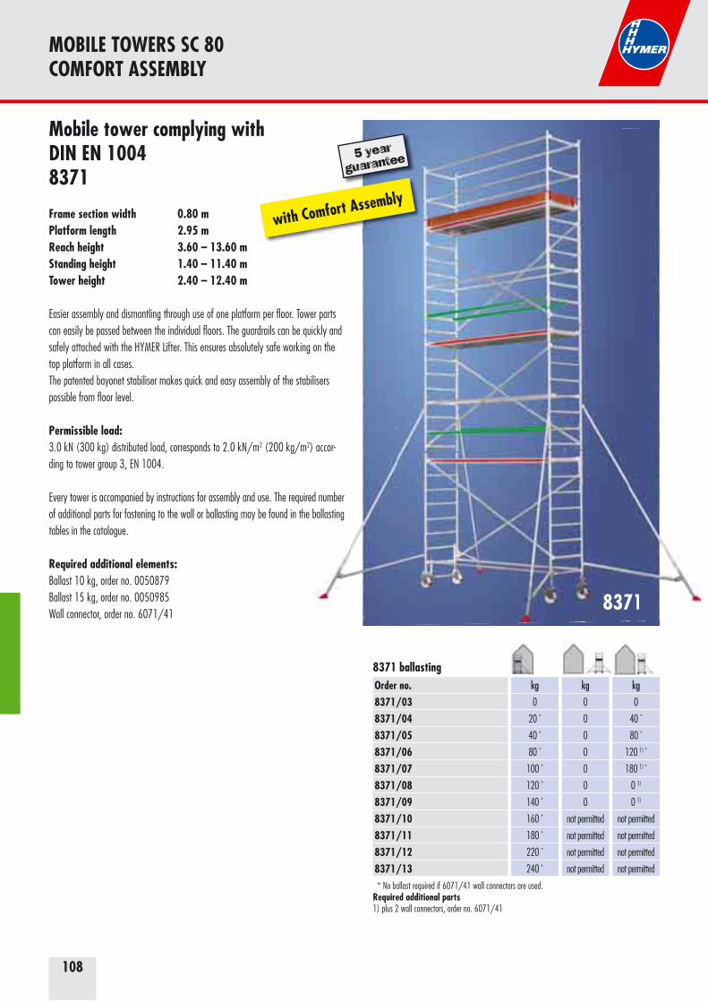
108
8371
MOBILE TOWERS SC 80COMFORT ASSEMBLY
8371
Mobile tower complying with DIN EN 10048371
Frame section width 0.80 mPlatform length 2.95 mReach height 3.60 – 13.60 mStanding height 1.40 – 11.40 mTower height 2.40 – 12.40 m
Easier assembly and dismantling through use of one platform per floor. Tower parts can easily be passed between the individual floors. The guardrails can be quickly and safely attached with the HYMER Lifter. This ensures absolutely safe working on the top platform in all cases.The patented bayonet stabiliser makes quick and easy assembly of the stabilisers possible from floor level.
Permissible load: 3.0 kN (300 kg) distributed load, corresponds to 2.0 kN/m2 (200 kg/m2) accor-ding to tower group 3, EN 1004.
Every tower is accompanied by instructions for assembly and use. The required number of additional parts for fastening to the wall or ballasting may be found in the ballasting tables in the catalogue.
Required additional elements: Ballast 10 kg, order no. 0050879 Ballast 15 kg, order no. 0050985 Wall connector, order no. 6071/41
5 year
guarantee
with Comfort Assembly
* No ballast required if 6071/41 wall connectors are used.Required additional parts1) plus 2 wall connectors, order no. 6071/41
Order no.8371/038371/048371/058371/068371/078371/088371/098371/108371/118371/128371/13
kg
0
20 *
40 *
80 *
100 *
120 *
140 *
160 *
180 *
220 *
240 *
kg
0
0
0
0
0
0
0
not permitted
not permitted
not permitted
not permitted
kg
0
40 *
80 *
120 1) *
180 1) *
0 1)
0 1)
not permitted
not permitted
not permitted
not permitted
8371 ballasting
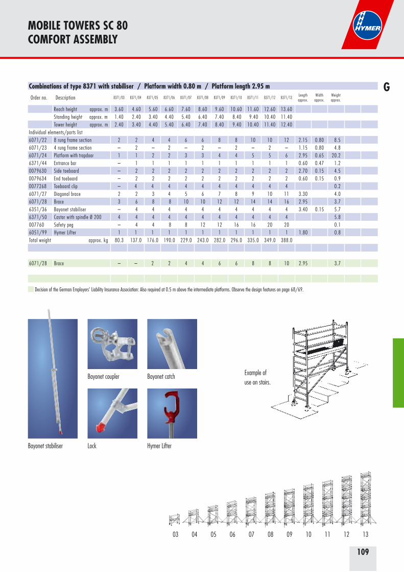
109
MOBILE TOWERS SC 80COMFORT ASSEMBLY
G
Example of use on stairs.
Combinations of type 8371 with stabiliser / Platform width 0.80 m / Platform length 2.95 m
Order no. Description 8371/03 8371/04 8371/05 8371/06 8371/07 8371/08 8371/09 8371/10 8371/11 8371/12 8371/13Lengthapprox.
Widthapprox.
Weightapprox.
Reach height approx. m 3.60 4.60 5.60 6.60 7.60 8.60 9.60 10.60 11.60 12.60 13.60Standing height approx. m 1.40 2.40 3.40 4.40 5.40 6.40 7.40 8.40 9.40 10.40 11.40Tower height approx. m 2.40 3.40 4.40 5.40 6.40 7.40 8.40 9.40 10.40 11.40 12.40
Individual elements/parts list 6071/22 8 rung frame section 2 2 4 4 6 6 8 8 10 10 12 2.15 0.80 8.56071/23 4 rung frame section – 2 – 2 – 2 – 2 – 2 – 1.15 0.80 4.86071/24 Plat form with trapdoor 1 1 2 2 3 3 4 4 5 5 6 2.95 0.65 20.26371/44 Entrance bar – 1 1 1 1 1 1 1 1 1 1 0.60 0.47 1.20079630 Side toeboard – 2 2 2 2 2 2 2 2 2 2 2.70 0.15 4.50079634 End toeboard – 2 2 2 2 2 2 2 2 2 2 0.60 0.15 0.90077268 Toeboard clip – 4 4 4 4 4 4 4 4 4 4 0.26071/27 Diagonal brace 2 2 3 4 5 6 7 8 9 10 11 3.30 4.06071/28 Brace 3 6 8 8 10 10 12 12 14 14 16 2.95 3.76351/36 Bayonet stabiliser – 4 4 4 4 4 4 4 4 4 4 3.40 0.15 5.76371/50 Castor with spindle Ø 200 4 4 4 4 4 4 4 4 4 4 4 5.8007760 Safety peg – 4 4 8 8 12 12 16 16 20 20 0.16051/99 Hymer Lifter 1 1 1 1 1 1 1 1 1 1 1 1.80 0.8Total weight approx. kg 80.3 137.0 176.0 190.0 229.0 243.0 282.0 296.0 335.0 349.0 388.0
6071/28 Brace – – 2 2 4 4 6 6 8 8 10 2.95 3.7
Decision of the German Employers‘ Liability Insurance Association: Also required at 0.5 m above the intermediate platforms. Observe the design features on page 68/69.
03 06 08 09 10 11 12 1304 0705
Bayonet coupler Bayonet catch
Bayonet stabiliser Hymer LifterLock

110
8771
MOBILE TOWERS SC 80COMFORT ASSEMBLY
8771
Mobile tower complying with DIN EN 10048771
Frame section width 0.80 mPlatform length 2.45 mReach height 3.40 – 13.40 mStanding height 1.40 – 11.40 mTower height 2.40 – 12.40 m
Easier assembly and dismantling through use of one platform per floor. Tower parts can easily be passed between the individual floors. The guardrails can be quickly and safely attached with the HYMER Lifter. This ensures absolutely safe working on the top platform in all cases.The patented bayonet stabiliser makes quick and easy assembly of the stabilisers possible from floor level.
Permissible load: 2.6 kN (260 kg) distributed load, corresponds to 2.0 kN/m2 (200 kg/m2) in accordance with tower group 3, EN 1004.
Every tower is accompanied by instructions for assembly and use. The required number of additional parts for fastening to the wall or ballasting may be found in the ballasting tables in the catalogue.
Required additional elements: Ballast 10 kg, order no. 0050879 Ballast 15 kg, order no. 0050985 Wall connector, order no. 6071/41
5 year
guarantee
with Comfort Assembly
* No ballast required if 6071/41 wall connectors are used.Required additional parts1) plus 2 wall connectors, order no. 6071/41
Order no.8771/038771/048771/058771/068771/078771/088771/098771/108771/118771/128771/13
kg
0
40 *
60 *
80 *
100 *
120 *
160 *
180 *
200 *
220 *
240 *
kg
0
0
0
0
0
0
0
not permitted
not permitted
not permitted
not permitted
kg
0
40 *
60 *
100 *
160 *
220 *
240 1) *
not permitted
not permitted
not permitted
not permitted
8771 ballasting

111
MOBILE TOWERS SC 80COMFORT ASSEMBLY
GCombinations of type 8771 with stabiliser / Platform width 0.80 m / Platform length 2.45 m
Order no. Description 8771/03 8771/04 8771/05 8771/06 8771/07 8771/08 8771/09 8771/10 8771/11 8771/12 8771/13Length
approx. mWidth
approx. mWeight
approx. kg
Reach height approx. m 3.40 4.40 5.40 6.40 7.40 8.40 9.40 10.40 11.40 12.40 13.40Standing height approx. m 1.40 2.40 3.40 4.40 5.40 6.40 7.40 8.40 9.40 10.40 11.40Tower height approx. m 2.40 3.40 4.40 5.40 6.40 7.40 8.40 9.40 10.40 11.40 12.40
Individual elements/parts list 6071/22 8 rung frame section 2 2 4 4 6 6 8 8 10 10 12 2.15 0.80 8.56071/23 4 rung frame section – 2 – 2 – 2 – 2 – 2 – 1.15 0.80 4.86771/24 Plat form with trapdoor 1 1 2 2 3 3 4 4 5 5 6 2.40 0.65 16.56371/44 Entrance bar – 1 1 1 1 1 1 1 1 1 1 0.60 0.47 1.20079631 Side toeboard – 2 2 2 2 2 2 2 2 2 2 2.20 0.15 3.50079634 End toeboard – 2 2 2 2 2 2 2 2 2 2 0.60 0.15 0.90077268 Toeboard clip – 4 4 4 4 4 4 4 4 4 4 0.26771/27 Diagonal brace 2 2 3 4 5 6 7 8 9 10 11 2.90 3.36378/27 Brace 3 6 8 8 10 10 12 12 14 14 16 2.45 2.56351/36 Bayonet stabiliser – 4 4 4 4 4 4 4 4 4 4 3.40 0.15 5.76371/50 Castor with spindle Ø 200 4 4 4 4 4 4 4 4 4 4 4 5.8007760 Safety peg – 4 4 8 8 12 12 16 16 20 20 0.16051/99 Hymer Lifter 1 1 1 1 1 1 1 1 1 1 1 1.80 0.8Total weight approx. kg 71.6 122.7 154.9 168.2 200.4 213.7 245.9 259.2 291.4 304.7 336.9
6378/27 Brace – – 2 2 4 4 6 6 8 8 10 2.45 2.5
Decision of the German Employers‘ Liability Insurance Association: Also required at 0.5 m above the intermediate platforms. Observe the design features on page 68/69.
03 06 08 09 10 11 12 1304 0705
Example of use on stairs.
Bayonet coupler Bayonet catch
Bayonet stabiliser Hymer LifterLock
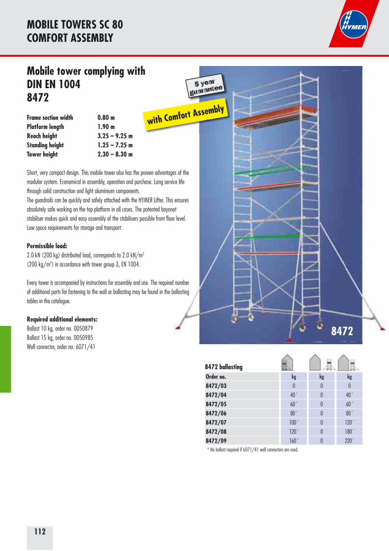
112
8472
MOBILE TOWERS SC 80COMFORT ASSEMBLY
8472
Mobile tower complying with DIN EN 10048472
Frame section width 0.80 mPlatform length 1.90 mReach height 3.25 – 9.25 mStanding height 1.25 – 7.25 mTower height 2.30 – 8.30 m
Short, very compact design. This mobile tower also has the proven advantages of the modular system. Economical in assembly, operation and purchase. Long service life through solid construction and light aluminium components.The guardrails can be quickly and safely attached with the HYMER Lifter. This ensures absolutely safe working on the top platform in all cases. The patented bayonet stabiliser makes quick and easy assembly of the stabilisers possible from floor level.Low space requirements for storage and transport.
Permissible load: 2.0 kN (200 kg) distributed load, corresponds to 2.0 kN/m2 (200 kg/m2) in accordance with tower group 3, EN 1004.
Every tower is accompanied by instructions for assembly and use. The required number of additional parts for fastening to the wall or ballasting may be found in the ballasting tables in the catalogue.
Required additional elements: Ballast 10 kg, order no. 0050879 Ballast 15 kg, order no. 0050985 Wall connector, order no. 6071/41
with Comfort Assembly
5 year
guarantee
* No ballast required if 6071/41 wall connectors are used.
Order no.8472/038472/048472/058472/068472/078472/088472/09
kg
0
40 *
60 *
80 *
100 *
120 *
160 *
kg
0
0
0
0
0
0
0
kg
0
40 *
60 *
80 *
120 *
180 *
220 *
8472 ballasting
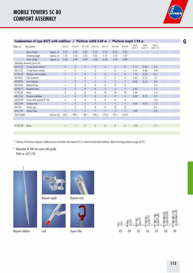
113
MOBILE TOWERS SC 80COMFORT ASSEMBLY
GCombinations of type 8472 with stabiliser / Platform width 0.80 m / Platform length 1.90 m
Order no. Description 8472/03 8472/04 8472/05 8472/06 8472/07 8472/08 8472/09Length
approx. mWidth
approx. mWeight
approx. kg
Reach height approx. m 3.25 4.25 5.25 6.25 7.25 8.25 9.25Standing height approx. m 1.25 2.25 3.25 4.25 5.25 6.25 7.25Tower height approx. m 2.30 3.30 4.30 5.30 6.30 7.30 8.30
Individual elements/parts list6071/22 8 rung frame section 2 2 4 4 6 6 8 2.15 0.80 8.56071/23 4 rung frame section – 2 – 2 – 2 – 1.15 0.80 4.86178/24 Platform with trapdoor 1 1 2 2 3 3 4 1.90 0.65 14.50079632 Side toeboard – 2 2 2 2 2 2 1.65 0.15 2.70079634 End toeboard – 2 2 2 2 2 2 0.60 0.15 0.90077268 Toeboard clip – 4 4 4 4 4 4 0.26378/27 Diagonal brace 2 2 3 4 5 6 7 2.45 2.56178/28 Brace 3 6 8 8 10 10 10 1.90 2.36351/36 Bayonet stabiliser – 4 4 4 4 4 4 3.40 0.15 5.76472/50* Castor with spindle Ø 150 4 4 4 4 4 4 4 4.06371/44 Entrance bar – 1 1 1 1 1 1 0.60 0.47 1.2007760 Safety peg – 4 4 8 8 12 12 0.16051/99 Hymer Lifter 1 1 1 1 1 1 1 1.80 0.8Total weight approx. kg 60.2 109.1 138.1 150.6 179.6 192.1 216.5
6178/28 Brace – – 2 2 4 4 6 1.90 2.1
Decision of the German Employers‘ Liability Insurance Association: Also required at 0.5 m above the intermediate platforms. Observe the design features on page 68/69.
* Alternative: Ø 200 mm castor with spindle Order no. 6371/50
03 06 08 0904 0705
Bayonet coupler Bayonet catch
Bayonet stabiliser Hymer LifterLock
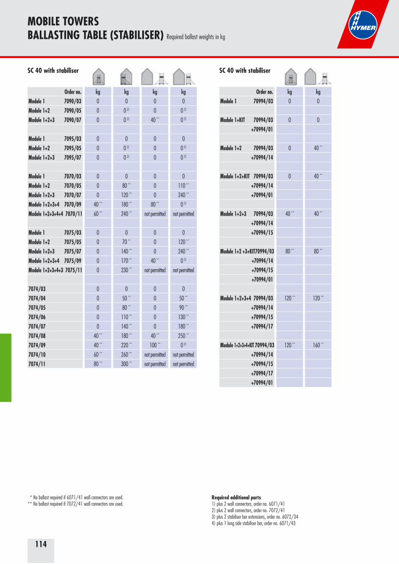
114
MOBILE TOWERSBALLASTING TABLE (STABILISER) Required ballast weights in kg
Order no.Module 1 7090/03Module 1+2 7090/05Module 1+2+3 7090/07
Module 1 7095/03Module 1+2 7095/05Module 1+2+3 7095/07
Module 1 7070/03Module 1+2 7070/05Module 1+2+3 7070/07Module 1+2+3+4 7070/09Module 1+2+3+4+4 7070/11
Module 1 7075/03Module 1+2 7075/05Module 1+2+3 7075/07Module 1+2+3+4 7075/09Module 1+2+3+4+3 7075/11
7074/03 7074/04 7074/057074/06 7074/07 7074/087074/09 7074/10 7074/11
kg
0
0 2)
0 2)
0
0 2)
0 2)
0
80 **
120 **
180 **
240 **
0
70 **
140 **
170 **
230 **
0
50 **
80 **
110 **
140 **
180 **
220 **
260 **
300 **
kg
0
0
40 **
0
0
0
0
0
0
80 **
not permitted
0
0
0
40 **
not permitted
0
0
0
0
0
40 **
100 **
not permitted
not permitted
kg
0
0 2)
0 2)
0
0 2)
0 2)
0
110 **
240 **
0 2)
not permitted
0
120 **
240 **
0 2)
not permitted
0
50 **
90 **
130 **
180 **
250 **
0 2)
not permitted
not permitted
SC 40 with stabiliser
kg
0
0
0
0
0
0
0
0
0
40 **
60 **
0
0
0
0
0
0
0
0
0
0
40 **
40 **
60 **
80 **
Order no.Module 1 70994/03
Module 1+KIT 70994/03 +70994/01
Module 1+2 70994/03 +70994/14
Module 1+2+KIT 70994/03 +70994/14 +70994/01
Module 1+2+3 70994/03 +70994/14 +70994/15
Module 1+2 +3+KIT 70994/03 +70994/14 +70994/15 +70994/01
Module 1+2+3+4 70994/03 +70994/14 +70994/15 +70994/17
Module 1+2+3+4+KIT 70994/03 +70994/14 +70994/15 +70994/17 +70994/01
kg
0
0
40 **
40 **
40 **
80 **
120 **
160 **
SC 40 with stabiliser
kg
0
0
0
0
40 **
80 **
120 **
120 **
Required additional parts1) plus 2 wall connectors, order no. 6071/412) plus 2 wall connectors, order no. 7072/413) plus 2 stabiliser bar extensions, order no. 6072/344) plus 1 long side stabiliser bar, order no. 6071/43
* No ballast required if 6071/41 wall connectors are used.** No ballast required if 7072/41 wall connectors are used.
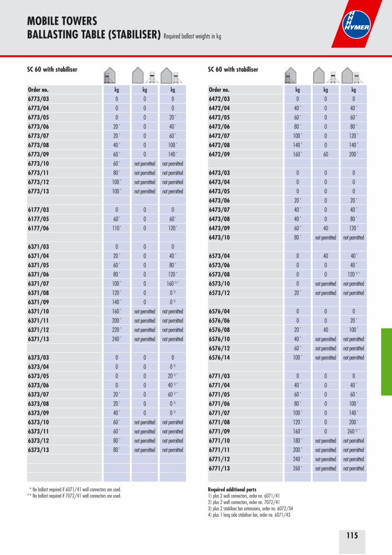
115
Order no.6773/036773/046773/056773/066773/076773/086773/096773/106773/116773/126773/13
6177/036177/056177/06
6371/036371/046371/056371/066371/076371/086371/096371/106371/116371/126371/13
6373/036373/046373/056373/066373/076373/086373/096373/106373/116373/126373/13
kg
0
0
0
20 *
20 *
40 *
60 *
60 *
80 *
100 *
100 *
0
60 *
110 *
0
20 *
60 *
80 *
100 *
120 *
140 *
160 *
200 *
220 *
240 *
0
0
0
0
20 *
20 *
40 *
60 *
60 *
80 *
80 *
kg
0
0
0
0
0
0
0
not permitted
not permitted
not permitted
not permitted
0
0
0
0
0
0
0
0
0
0
not permitted
not permitted
not permitted
not permitted
0
0
0
0
0
0
0
not permitted
not permitted
not permitted
not permitted
kg
0
0
20 *
40 *
60 *
100 *
140 *
not permitted
not permitted
not permitted
not permitted
0
60 *
120 *
0
40 *
80 *
120 *
160 1) *
0 1)
0 1)
not permitted
not permitted
not permitted
not permitted
0
0 1)
20 1) *
40 1) *
60 1) *
0 1)
0 1)
not permitted
not permitted
not permitted
not permitted
SC 60 with stabiliser
MOBILE TOWERSBALLASTING TABLE (STABILISER) Required ballast weights in kg
Order no.6472/036472/046472/056472/066472/076472/086472/09
6473/036473/046473/056473/066473/076473/086473/096473/10
6573/046573/066573/086573/106573/12
6576/046576/066576/086576/106576/126576/14
6771/036771/046771/056771/066771/076771/086771/096771/106771/116771/126771/13
kg
0
40 *
60 *
80 *
100 *
140 *
160 *
0
0
0
20 *
40 *
40 *
60 *
80 *
0
0
0
0
20 *
0
0
20 *
40 *
60 *
100 *
0
40 *
60 *
80 *
100 *
120 *
160 *
180 *
200 *
240 *
260 *
kg
0
0
0
0
0
0
60
0
0
0
0
0
0
40
not permitted
40
0
0
not permitted
not permitted
0
0
40
not permitted
not permitted
not permitted
0
0
0
0
0
0
0
not permitted
not permitted
not permitted
not permitted
kg
0
40 *
60 *
80 *
120 *
140 *
200 *
0
0
0
20 *
40 *
80 *
120 *
not permitted
40 *
40 *
120 1) *
not permitted
not permitted
0
20 *
100 *
not permitted
not permitted
not permitted
0
40 *
60 *
100 *
140 *
200 *
260 1) *
not permitted
not permitted
not permitted
not permitted
SC 60 with stabiliser
Required additional parts1) plus 2 wall connectors, order no. 6071/412) plus 2 wall connectors, order no. 7072/413) plus 2 stabiliser bar extensions, order no. 6072/344) plus 1 long side stabiliser bar, order no. 6071/43
* No ballast required if 6071/41 wall connectors are used.** No ballast required if 7072/41 wall connectors are used.
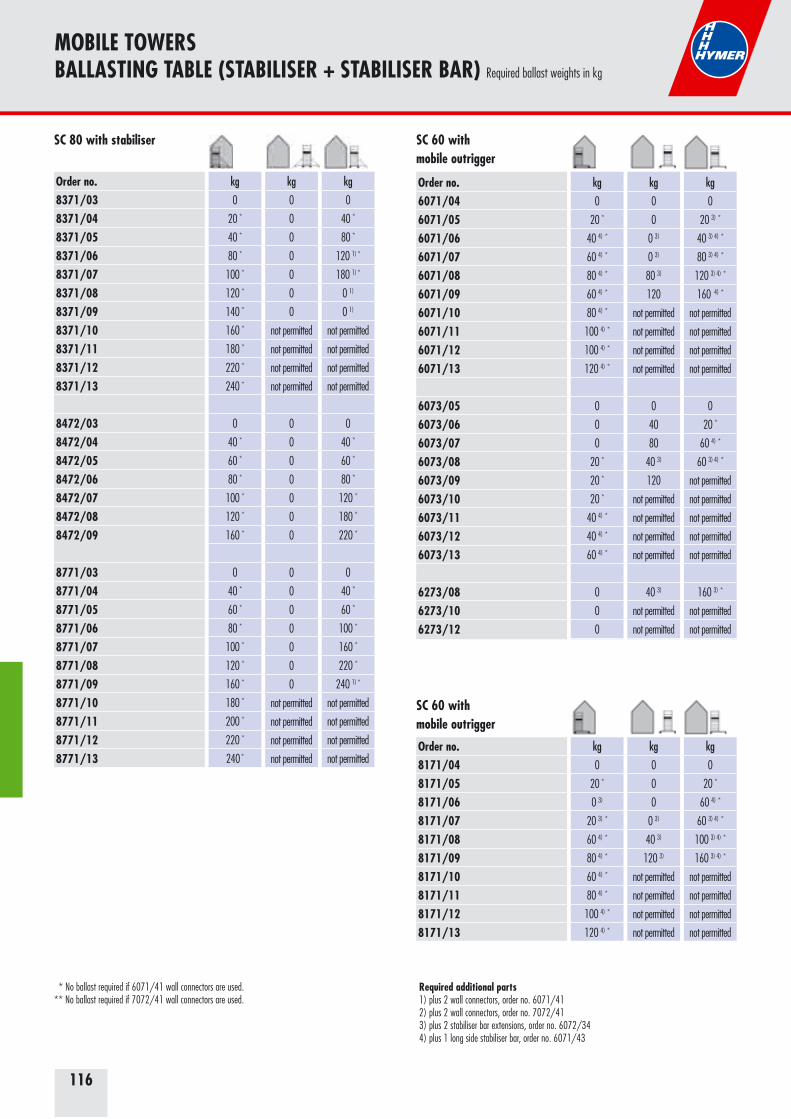
116
MOBILE TOWERSBALLASTING TABLE (STABILISER + STABILISER BAR) Required ballast weights in kg
Order no.6071/046071/056071/066071/076071/086071/096071/106071/116071/126071/13
6073/056073/066073/076073/086073/096073/106073/116073/126073/13
6273/086273/106273/12
kg
0
20 *
40 4) *
60 4) *
80 4) *
60 4) *
80 4) *
100 4) *
100 4) *
120 4) *
0
0
0
20 *
20 *
20 *
40 4) *
40 4) *
60 4) *
0
0
0
kg
0
0
0 3)
0 3)
80 3)
120
not permitted
not permitted
not permitted
not permitted
0
40
80
40 3)
120
not permitted
not permitted
not permitted
not permitted
40 3)
not permitted
not permitted
kg
0
20 3) *
40 3) 4) *
80 3) 4) *
120 3) 4) *
160 4) *
not permitted
not permitted
not permitted
not permitted
0
20 *
60 4) *
60 3) 4) *
not permitted
not permitted
not permitted
not permitted
not permitted
160 3) *
not permitted
not permitted
Order no.8171/048171/058171/068171/078171/088171/098171/108171/118171/128171/13
kg
0
20 *
0 3)
20 3) *
60 4) *
80 4) *
60 4) *
80 4) *
100 4) *
120 4) *
kg
0
0
0
0 3)
40 3)
120 3)
not permitted
not permitted
not permitted
not permitted
kg
0
20 *
60 4) *
60 3) 4) *
100 3) 4) *
160 3) 4) *
not permitted
not permitted
not permitted
not permitted
SC 60 with mobile outrigger
SC 60 with mobile outrigger
Order no.8371/038371/048371/058371/068371/078371/088371/098371/108371/118371/128371/13
8472/038472/048472/058472/068472/078472/088472/09
8771/038771/048771/058771/068771/078771/088771/098771/108771/118771/128771/13
kg
0
20 *
40 *
80 *
100 *
120 *
140 *
160 *
180 *
220 *
240 *
0
40 *
60 *
80 *
100 *
120 *
160 *
0
40 *
60 *
80 *
100 *
120 *
160 *
180 *
200 *
220 *
240 *
kg
0
0
0
0
0
0
0
not permitted
not permitted
not permitted
not permitted
0
0
0
0
0
0
0
0
0
0
0
0
0
0
not permitted
not permitted
not permitted
not permitted
kg
0
40 *
80 *
120 1) *
180 1) *
0 1)
0 1)
not permitted
not permitted
not permitted
not permitted
0
40 *
60 *
80 *
120 *
180 *
220 *
0
40 *
60 *
100 *
160 *
220 *
240 1) *
not permitted
not permitted
not permitted
not permitted
SC 80 with stabiliser
Required additional parts1) plus 2 wall connectors, order no. 6071/412) plus 2 wall connectors, order no. 7072/413) plus 2 stabiliser bar extensions, order no. 6072/344) plus 1 long side stabiliser bar, order no. 6071/43
* No ballast required if 6071/41 wall connectors are used.** No ballast required if 7072/41 wall connectors are used.
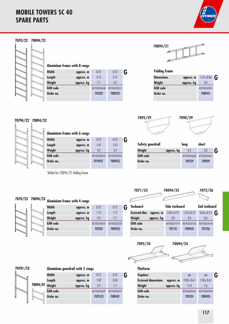
117
MOBILE TOWERS SC 40 SPARE PARTS
Width approx. mLength approx. mWeight approx. kgEAN codeOrder no.
0.72
2.15
7.1
4019502345638
707022
0.72
2.17
4.2
4019502325517
7009422
G
TrapdoorExternal dimensions approx. mWeight approx. kgEAN codeOrder no.
yes
2.08 x 0.61
11.8
4019502346475
709524
yes
1.58 x 0.61
7.6
4019502342958
7089424
Platform
External dim. approx. mWeight approx. kgEAN codeOrder no.
2.03 x 0.17
3,9
4019502314719
707125
1.53 x 0.17
2,4
4019502347106
7009425
0.66 x 0.15
0,6
4019502318144
707226
Toeboard
70094/22
7095/24
7071/25
Width approx. mLength approx. mWeight approx. kgEAN codeOrder no.
0.72
1.67
3.2
4019502343122
7079422 *
0.72
1.67
3.2
4019502347465
7089422
Dimensions approx. mWeight approx. kgEAN codeOrder no.
1.57 x 0.36
4.4
4019502342941
7089421
Folding frame
70894/22
70894/21
Width approx. mLength approx. mWeight approx. kgEAN codeOrder no.
0.72
1.15
4.2
4019502345614
707023
0.72
1.17
2.1
4019502325524
7009423
70094/23
Width approx. mLength approx. mWeight approx. kgEAN codeOrder no.
0.72
1.02
2.5
4019502345607
7070123
0.72
0.53
1.1
4019502345591
7089401
Aluminium guardrail with 2 rungs70701/23
Weight approx. kgEAN codeOrder no.
4.2
4019502346468
709529
3.2
4019502346451
709029
Safety guardrail long short
Side toeboard End toeboard
7072/26
70894/24
7070/22
7070/23
70894/01
70094/25
7090/297095/29
Aluminium frame with 8 rungs
Aluminium frame with 6 rungs
Aluminium frame with 4 rungs
G
G
G G
G
G
G
70794/22 *
* Drilled for 70894/21 folding frame
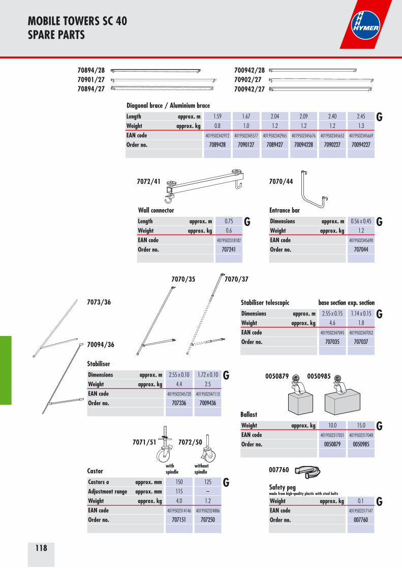
118
Length approx. mWeight approx. kgEAN codeOrder no.
0.75
0.6
4019502318182
707241
Wall connector
7072/41
MOBILE TOWERS SC 40 SPARE PARTS
Weight approx. kgEAN codeOrder no.
0.1
4019502317147
007760
007760
Dimensions approx. mWeight approx. kgEAN codeOrder no.
0.56 x 0.45
1.2
4019502345690
707044
Entrance bar
7070/44
Dimensions approx. mWeight approx. kgEAN codeOrder no.
2.55 x 0.15
4.6
4019502347045
707035
1.14 x 0.15
1.8
4019502347052
707037
Stabiliser telescopic base section exp. section
Weight approx. kgEAN codeOrder no.
10.0
4019502317031
0050879
15.0
4019502317048
0050985
Ballast
0050879 0050985
700942/27
700942/2870902/27
70894/27
70894/2870901/27
Length approx. mWeight approx. kgEAN codeOrder no.
1.59
0.8
4019502342972
7089428
1.67
1.0
4019502345577
7090127
2.04
1.2
4019502342965
7089427
2.09
1.2
4019502345676
70094228
2.40
1.2
4019502345652
7090227
2.45
1.3
4019502345669
70094227
Diagonal brace / Aluminium brace
G
7070/377070/35
G G
G
G
GSafety peg made from high-quality plastic with steel bolts
Dimensions approx. mWeight approx. kgEAN codeOrder no.
2.55 x 0.10
4.4
4019502345720
707336
1.72 x 0.10
2.5
4019502347113
7009436
Stabiliser
70094/36
7073/36
G
Castors ø approx. mmAdjustment range approx. mmWeight approx. kgEAN codeOrder no.
150
115
4.0
4019502314146
707151
125
–
1.2
4019502324886
707250
Castorwithout spindle
with spindle
7072/507071/51
G

119
MOBILE TOWERS SC 60/SC 80 SPARE PARTS
Width approx. mLength approx. mWeight approx. kgEAN codeOrder no.
0.80
1.15
4.8
4019502311145
607123
1.50
1.15
6.8
4019502311534
607323
Width approx. mLength approx. mWeight approx. kgEAN codeOrder no.
0.80
1.00
2.8
4019502311756
607823
1.50
1.00
3.8
4019502311787
607923
Aluminium frame with 4 rungs
Aluminium guardrail with 2 rungs
6071/23
6078/23
Width approx. mLength approx. mWeight approx. kgEAN codeOrder no.
0.80
1.65
6.8
4019502311749
607822
GAluminium frame with 6 rungs
6078/22
6073/23
6079/23
G
G
Width approx. mLength approx. mWeight approx. kgEAN codeOrder no.
0.80
2.15
8.5
4019502311138
607122
1.50
2.15
12.5
4019502311527
607322
Aluminium frame with 8 rungs
6071/22 6073/22
G
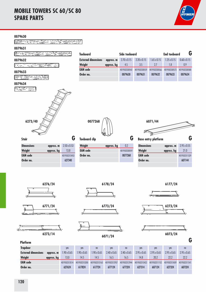
120
MOBILE TOWERS SC 60/SC 80 SPARE PARTS
External dimensions approx. mWeight approx. kgEAN codeOrder no.
2.70 x 0.15
4.5
4019502330542
0079630
2.20 x 0.15
3.5
4019502330559
0079631
1.65 x 0.15
2.7
4019502330566
0079632
1.25 x 0.15
1.8
4019502330573
0079633
0.60 x 0.15
0.9
4019502330580
0079634
GToeboard Side toeboard End toeboard
0079630
0079631
0079632
0079633
0079634
Dimensions approx. mWeight approx. kgEAN codeOrder no.
2.50 x 0.53
13.8
4019502313453
627340
Dimensions approx. mWeight approx. kgEAN codeOrder no.
2.95 x 0.55
21.0
4019502311329
607144
Weight approx. kgEAN codeOrder no.
0.2
4019502330597
0077268
GGGStair Toeboard clip Base entry platform
6273/40 0077268
TrapdoorExternal dimensions approx. mWeight approx. kgEAN codeOrder no.
yes
1.90 x 0.65
13.0
4019502313514
627624
yes
1.90 x 0.65
14.5
4019502313200
617824
no
1.90 x 0.65
14.5
4019502313163
617724
yes
2.40 x 0.65
16.5
4019502312937
677124
no
2.40 x 0.65
16.5
4019502312944
677324
yes
2.95 x 0.65
14.8
4019502313422
627314
yes
2.95 x 0.65
20.2
4019502311152
607124
yes
2.95 x 0.65
22.2
4019502313439
627324
no
2.95 x 0.65
22.2
4019502311541
607324
Platform
6178/246276/24 6177/24
6771/24 6773/24
6071/24
6273/24
6273/14 6073/24
G
6071/44
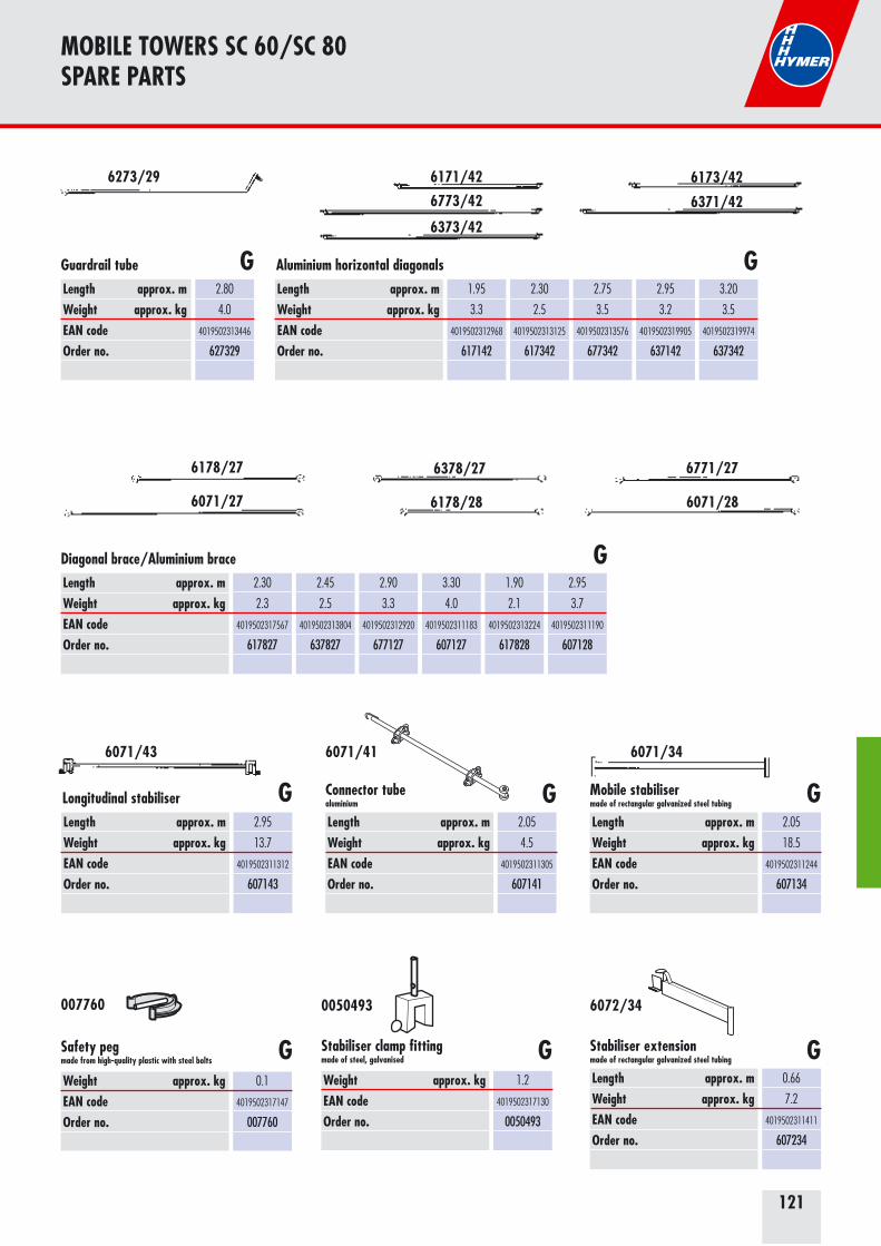
121
MOBILE TOWERS SC 60/SC 80 SPARE PARTS
Length approx. mWeight approx. kgEAN codeOrder no.
2.80
4.0
4019502313446
627329
Guardrail tube
Length approx. mWeight approx. kgEAN codeOrder no.
1.95
3.3
4019502312968
617142
2.30
2.5
4019502313125
617342
2.75
3.5
4019502313576
677342
2.95
3.2
4019502319905
637142
3.20
3.5
4019502319974
637342
Aluminium horizontal diagonalsG G
Length approx. mWeight approx. kgEAN codeOrder no.
2.30
2.3
4019502317567
617827
2.45
2.5
4019502313804
637827
2.90
3.3
4019502312920
677127
3.30
4.0
4019502311183
607127
1.90
2.1
4019502313224
617828
2.95
3.7
4019502311190
607128
Diagonal brace/Aluminium brace G
6273/29 6173/426171/42
6371/426773/42
6373/42
Weight approx. kgEAN codeOrder no.
0.1
4019502317147
007760
Safety peg made from high-quality plastic with steel bolts G
Length approx. mWeight approx. kgEAN codeOrder no.
2.95
13.7
4019502311312
607143
Longitudinal stabiliser G
Length approx. mWeight approx. kgEAN codeOrder no.
0.66
7.2
4019502311411
607234
Stabiliser extension made of rectangular galvanized steel tubing G
Length approx. mWeight approx. kgEAN codeOrder no.
2.05
18.5
4019502311244
607134
Mobile stabiliser made of rectangular galvanized steel tubing G
Weight approx. kgEAN codeOrder no.
1.2
4019502317130
0050493
Stabiliser clamp fitting made of steel, galvanised G
Length approx. mWeight approx. kgEAN codeOrder no.
2.05
4.5
4019502311305
607141
G
6771/276178/27
6071/286178/28
6378/27
6071/27
6071/43 6071/34
007760 0050493 6072/34
Connector tube aluminium
6071/41

122
MOBILE TOWERS SC 60/SC 80 SPARE PARTS
Dimensions approx. mWeight approx. kgEAN codeOrder no.
1.65 x 1.00
19.0
4019502313156
617721
GFolding framewith frame sections
Castors ø approx. mmAdjustment range approx. mmWeight approx. kgEAN codeOrder no.
200
220
5.8
4019502318717
637150
200
220
5.8
4019502311343
607150
150
115
4.0
4019502314146
647250
GCastor with spindle
Castors ø approx. mmWeight approx. kgEAN codeOrder no.
125
1.2
4019502342886
617750
Castor
6177/21
6371/50 6071/50
6472/50 6177/50
G
Dimensions approx. mWeight approx. kgEAN codeOrder no.
3.40 x 0.15
5.7
4019502335677
635136
Dimensions approx. mWeight approx. kgEAN codeOrder no.
2.70 x 0.15
5.7
4019502311367
637136
Stabiliser including coupler G
Length approx. mWeight approx. kgEAN codeOrder no.
1.80
0.8
4019502335684
605199
Hymer Lifter G
Dimensions approx. mWeight approx. kgEAN codeOrder no.
0.60 x 0.47
1.2
4019502318724
637144
Entrance bar
GBallast 0050879 0050985 6371/44
6051/996371/36
Weight approx. kgEAN codeOrder no.
1.4
4019502336117
607146
Entrance bar 6071/46
Weight approx. kgEAN codeOrder no.
10.0
4019502317031
0050879
15.0
4019502317048
0050985
G
G
Bayonet stabiliserincluding coupler G6351/36
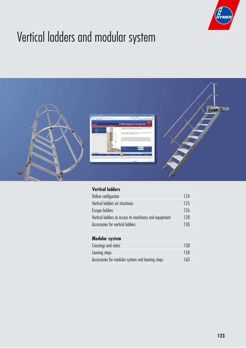
123
Vertical laddersOnline configurator 124Vertical ladders on structures 125Escape ladders 126Vertical ladders as access to machinery and equipment 128Accessories for vertical ladders 130
Modular system Crossings and stairs 138Leaning steps 158Accessories for modular system and leaning steps 160
Vertical ladders and modular system
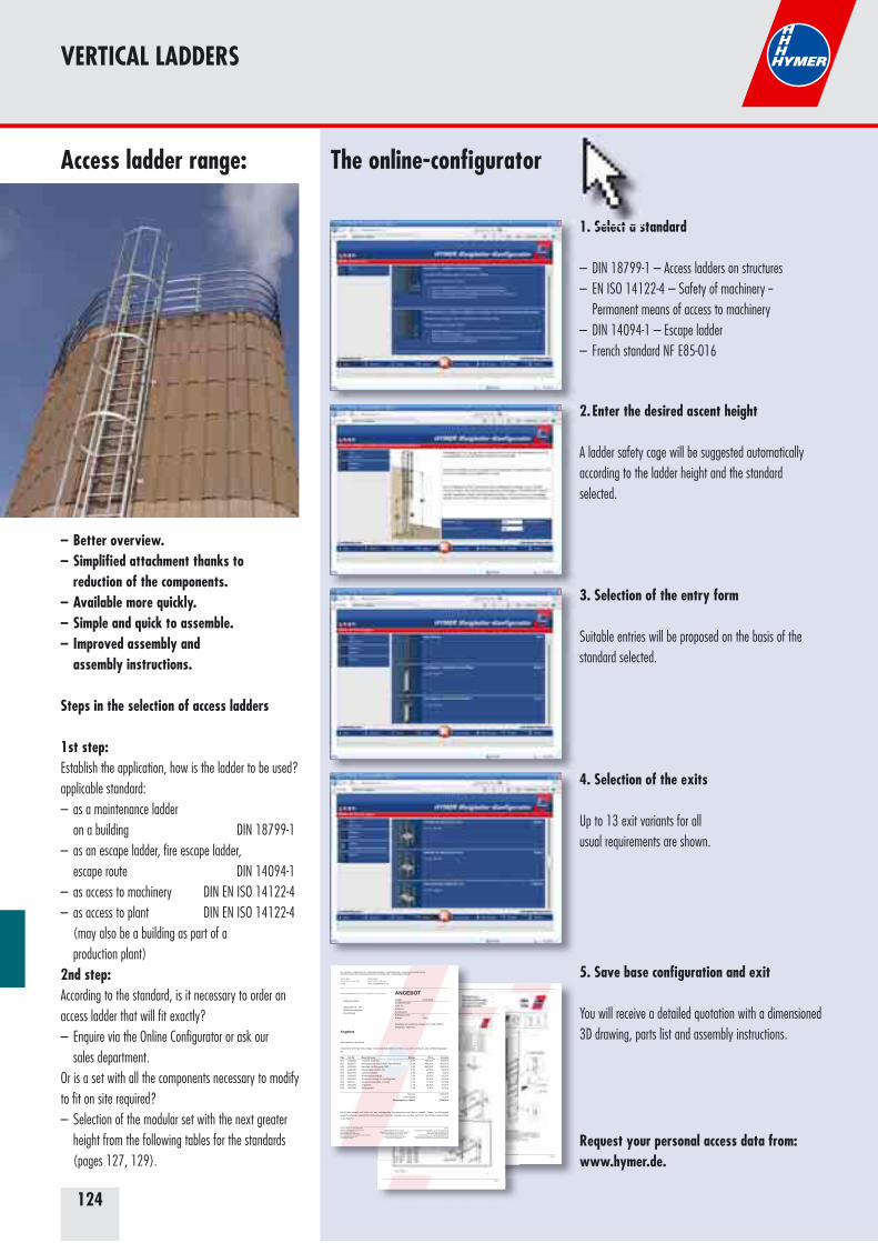
124
VERTICAL LADDERS
Access ladder range:
– Better overview.– Simplified attachment thanks to reduction of the components.– Available more quickly.– Simple and quick to assemble.– Improved assembly and assembly instructions.
Steps in the selection of access ladders
1st step: Establish the application, how is the ladder to be used? applicable standard:– as a maintenance ladder on a building DIN 18799-1– as an escape ladder, fire escape ladder, escape route DIN 14094-1– as access to machinery DIN EN ISO 14122-4– as access to plant DIN EN ISO 14122-4 (may also be a building as part of a production plant)2nd step: According to the standard, is it necessary to order an access ladder that will fit exactly?– Enquire via the Online Configurator or ask our sales department. Or is a set with all the components necessary to modify to fit on site required?– Selection of the modular set with the next greater height from the following tables for the standards (pages 127, 129).
1. Select a standard
– DIN 18799-1 – Access ladders on structures– EN ISO 14122-4 – Safety of machinery -- Permanent means of access to machinery– DIN 14094-1 – Escape ladder– French standard NF E85-016
2. Enter the desired ascent height
A ladder safety cage will be suggested automatically according to the ladder height and the standard selected.
4. Selection of the exits
Up to 13 exit variants for all usual requirements are shown.
3. Selection of the entry form
Suitable entries will be proposed on the basis of the standard selected.
5. Save base configuration and exit
You will receive a detailed quotation with a dimensioned 3D drawing, parts list and assembly instructions.
Request your personal access data from: www.hymer.de.
Seite 5
Seite 8
ALU-LEITERN · FAHRGERÜSTE · VERLADESCHIENEN · TAPEZIERTISCHE · SONDERKONSTRUKTIONENAUSRÜSTUNGEN UND KAROSSERIETEILE FÜR OMNIBUSSE · REISEMOBILZUBEHÖR
Unsere Ref.:Tel.: 0 75 22 / 7 00 - 150E-Mail:
Tobias ZodelFax: 0 75 22 / 7 00 - [email protected]
HYMER Leichtmetallbau GmbH & Co. KG · Postfach 1265 · D-88228 Wangen i. A.
Wolfgang Mach
Biberacher Str. 12488339 Bad WaldseeDeutschland
ANGEBOTDatum: 03.09.2009Kundennummer:Auftr.-Nr.:Referenz:Kommission:Auftragsanzahl: 1Rabatt: 0,0%
Steigleiter an baulichen Anlagen nach DIN 18799-1Steighöhe: 4000 mm
Angebot
Sehr geehrter Herr Mach,
wir danken Ihnen für Ihre Anfrage. Wunschgemäß bieten wir Ihnen zu unseren Verkaufs- und Lieferbedingungenan:
Pos Art.-Nr. Bezeichnung Menge Preis Gesamt001 0053966 Leiterteil 3640 mm 1.00 163,00 € 163,00 €002 0051637 Aufstiegsperre schwenkbar, abschließbar 1.00 456,00 € 456,00 €003 0053304 Ausstieg mit Übergang 1163 1.00 863,00 € 863,00 €004 0050139 Wandhaken 210mm Alu 6.00 13,50 € 81,00 €005 0077059 Lamellenstopfen 2.00 1,50 € 3,00 €006 0051600 Rückenschutzring kpl. 2.00 30,00 € 60,00 €007 0053324 Rückenschutzring für Ausstieg breit 1.00 40,00 € 40,00 €008 002342 Rückenschutzstrebe, C-Profil 4.05 17,50 € 87,50 €009 0053340 Zugstrebe 1.00 20,50 € 20,50 €010 0051566 Bodenwinkel 2.00 5,00 € 10,00 €
Summe 1784,00 €0,0% Rabatt 0,00 €
Gesamtpreis o. MwSt. 1784,00 €
Die Preise wurden auf Basis der uns vorliegenden Informationen und Skizzen erstellt. Sollten im Auftragsfallabweichende oder zusätzliche Anforderungen auftreten, behalten wir uns das Recht vor, die Preise entsprechendzu korrigieren.
Unsere Ust.Id.-Nr.: DE147359150 Seite 1HYMER Leichtmetallbau GmbH & Co. KG88239 Wangen-KäferhofenHandelsregister Ulm HRA 620636persönlich haftende Gesellschafterin: Hymer & LangVerwaltungsgesellschaft mbHSitz in Wangen/Allgäu
Handelsregister Ulm HRB 620571Geschäftsführer: Eberhard Lang u. Björn Hillesheim
88239 Wangen/Allgäu, Tel.: (0 75 22) 700 - 0Homepage www.hymer-alu.de
Zertifiziert nach DIN EN ISO 9001:2000Steuernummer: 91070/02371
Kreissparkasse Ravensburg, Kto. 211222 (BLZ 650 501 10)SWIFT / BIC-Code: SOLA DE S1RVBIBAN: DE77 6505 0110 0000 2112 22
Volksbank Wangen, Kto. 42422000 (BLZ 650 920 10)Deutsche Bank Ravensburg, Kto. 501 130 (BLZ 650 700 84)
Schweiz. Bankgesellschaft, St. Margarethen 592.136.01 B
Select a s
The online-configurator
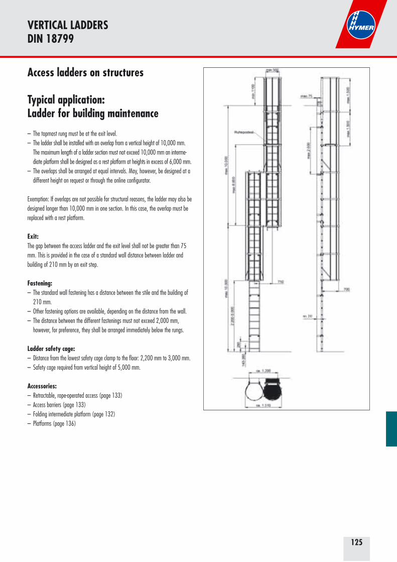
125
VERTICAL LADDERSDIN 18799
Access ladders on structures
Typical application: Ladder for building maintenance
– The topmost rung must be at the exit level.– The ladder shall be installed with an overlap from a vertical height of 10,000 mm. The maximum length of a ladder section must not exceed 10,000 mm an interme- diate platform shall be designed as a rest platform at heights in excess of 6,000 mm.– The overlaps shall be arranged at equal intervals. May, however, be designed at a different height on request or through the online configurator. Exemption: If overlaps are not possible for structural reasons, the ladder may also be designed longer than 10,000 mm in one section. In this case, the overlap must be replaced with a rest platform.
Exit: The gap between the access ladder and the exit level shall not be greater than 75 mm. This is provided in the case of a standard wall distance between ladder and building of 210 mm by an exit step.
Fastening: – The standard wall fastening has a distance between the stile and the building of 210 mm. – Other fastening options are available, depending on the distance from the wall. – The distance between the different fastenings must not exceed 2,000 mm, however, for preference, they shall be arranged immediately below the rungs.
Ladder safety cage:– Distance from the lowest safety cage clamp to the floor: 2,200 mm to 3,000 mm.– Safety cage required from vertical height of 5,000 mm.
Accessories: – Retractable, rope-operated access (page 133)– Access barriers (page 133)– Folding intermediate platform (page 132)– Platforms (page 136)
min. 200
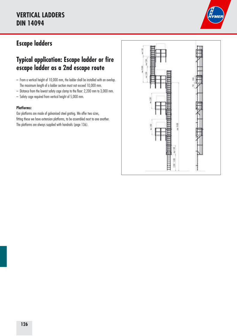
126
VERTICAL LADDERSDIN 14094
Escape ladders
Typical application: Escape ladder or fire escape ladder as a 2nd escape route
– From a vertical height of 10,000 mm, the ladder shall be installed with an overlap. The maximum length of a ladder section must not exceed 10,000 mm.– Distance from the lowest safety cage clamp to the floor: 2,200 mm to 3,000 mm.– Safety cage required from vertical height of 5,000 mm.
Platforms: Our platforms are made of galvanised steel grating. We offer two sizes, fitting these we have extension platforms, to be assembled next to one another. The platforms are always supplied with handrails (page 136).
min 1
.100
max 1
.500
max 1
0.000
min.
2.200
min.
2.200
min.
2.200
max 1
.500
2.200
bis 3
.000
max.
10.00
0
750
1000
–

127
Building/ascent height to [m]
Number of ladder sections [no.]1960 mm 2800 mm 3640 mm0051522 0053965 0053966
Overlap ** at height [m]
Quantityof wall faste-
nings
Quantityof safety cage
clamps *Order no.
up to 10 m, single section2.68 1 - - - 6 - 3185103.52 - 1 - - 8 - 3185134.64 2 - - - 8 - 318517
from an ascent height of 5 m including ladder safety cage beginning at a maximum of 3 m above the ground5.48 1 1 - - 10 3 + 1 3185206.60 3 - - - 10 4 + 1 3185247.44 2 1 - - 10 4 + 1 3185278.28 1 2 - - 12 5 + 1 3185309.12 - 3 - - 11 6 + 1 3185339.96 - 2 1 - 14 6 + 1 318536
from ascent height of 10 m, overlapped design10.80 5 1 - 5.54 20 7 + 1 31854812.20 - 5 - 6.10 20 9 + 1 31855313.88 - 3 2 6.94 22 10 + 1 31855915.56 - 1 4 7.78 24 11 + 1 318565
from ascent height of 16 m, overlapped design with additional resting platform17.80 - 7 - 8.90 24 13 + 1 31857319.48 1 3 3 9.74 28 14 + 1 318579
*) Standard safety cage clamps (order no. 0051600) and a safety cage clamp for the narrow exit (order no. 0054051) **) includes 1 fixed platform each (order no. 0051630), two 3/4 clamps (order no. 0053981) with connector (order no. 0053332)
VERTICAL LADDERSSET DIN 18799 / DIN 14094
AluminiumIncluded in scope of delivery: – Standard wall fastenings (order no. 0050139)– Adequate ladder flanges (order no. 0077209)– One straight narrow exit (order no. 0053291)– Narrow exit step (order no. 0054038)– Standard safety cage clamps (order no. 0051600) and a clamp fitting
the straight narrow exit (order no. 0054038) plus safety cage braces (order no. 002342) to be cut to length– One diagonal tie pair per ladder section (order no. 0053340)– From ascent height > 16 m one folding intermediate platform (order no.
0051635)
DIN 18799 / DIN 14094 access ladders
G
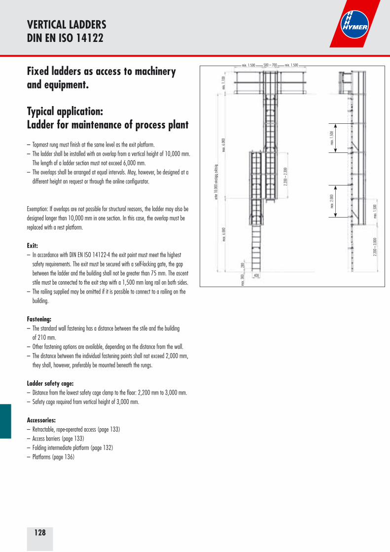
128
Fixed ladders as access to machinery and equipment.
Typical application: Ladder for maintenance of process plant
– Topmost rung must finish at the same level as the exit platform.– The ladder shall be installed with an overlap from a vertical height of 10,000 mm. The length of a ladder section must not exceed 6,000 mm. – The overlaps shall be arranged at equal intervals. May, however, be designed at a different height on request or through the online configurator.
Exemption: If overlaps are not possible for structural reasons, the ladder may also be designed longer than 10,000 mm in one section. In this case, the overlap must be replaced with a rest platform.
Exit: – In accordance with DIN EN ISO 14122-4 the exit point must meet the highest safety requirements. The exit must be secured with a self-locking gate, the gap between the ladder and the building shall not be greater than 75 mm. The ascent stile must be connected to the exit step with a 1,500 mm long rail on both sides.– The railing supplied may be omitted if it is possible to connect to a railing on the building.
Fastening: – The standard wall fastening has a distance between the stile and the building of 210 mm.– Other fastening options are available, depending on the distance from the wall. – The distance between the individual fastening points shall not exceed 2,000 mm, they shall, however, preferably be mounted beneath the rungs.
Ladder safety cage: – Distance from the lowest safety cage clamp to the floor: 2,200 mm to 3,000 mm.– Safety cage required from vertical height of 3,000 mm.
Accessories: – Retractable, rope-operated access (page 133)– Access barriers (page 133)– Folding intermediate platform (page 132)– Platforms (page 136)
max.
6.00
0
max.
1.50
0
min.
1.10
0ma
x. 6.
000
unter
10.
000
einzü
gig zu
lässig
2.20
0 –
2.30
0
max.
1.50
02.
200
– 3.
000
max.
300
280
400
min. 1.500 min. 1.500500 – 700
max.
2.00
0
VERTICAL LADDERSDIN EN ISO 14122
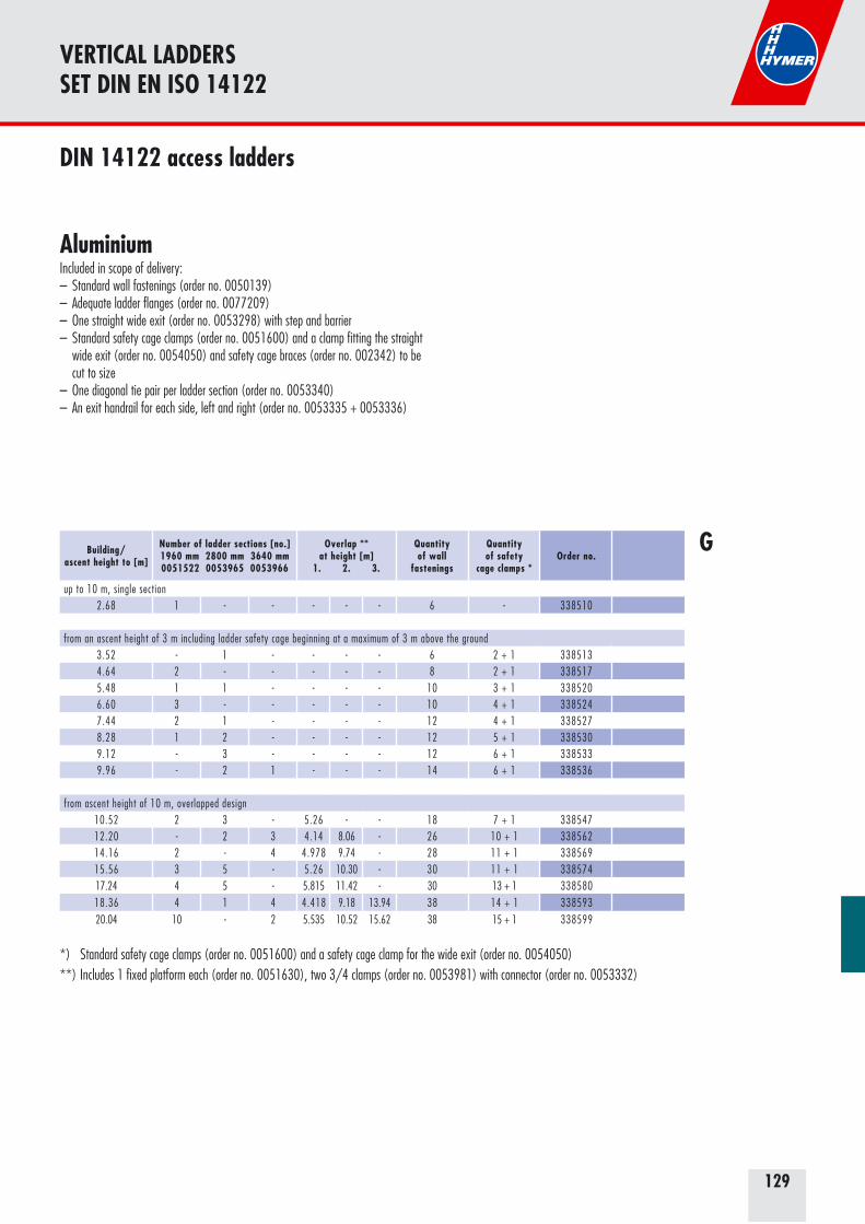
129
Building/ascent height to [m]
Number of ladder sections [no.]1960 mm 2800 mm 3640 mm0051522 0053965 0053966
Overlap ** at height [m]
1. 2. 3.
Quantityof wall
fastenings
Quantityof safety
cage clamps *Order no.
up to 10 m, single section2.68 1 - - - - - 6 - 338510
from an ascent height of 3 m including ladder safety cage beginning at a maximum of 3 m above the ground3.52 - 1 - - - - 6 2 + 1 3385134.64 2 - - - - - 8 2 + 1 3385175.48 1 1 - - - - 10 3 + 1 3385206.60 3 - - - - - 10 4 + 1 3385247.44 2 1 - - - - 12 4 + 1 3385278.28 1 2 - - - - 12 5 + 1 3385309.12 - 3 - - - - 12 6 + 1 3385339.96 - 2 1 - - - 14 6 + 1 338536
from ascent height of 10 m, overlapped design10.52 2 3 - 5.26 - - 18 7 + 1 33854712.20 - 2 3 4.14 8.06 - 26 10 + 1 33856214.16 2 - 4 4.978 9.74 - 28 11 + 1 33856915.56 3 5 - 5.26 10.30 - 30 11 + 1 33857417.24 4 5 - 5.815 11.42 - 30 13 + 1 33858018.36 4 1 4 4.418 9.18 13.94 38 14 + 1 33859320.04 10 - 2 5.535 10.52 15.62 38 15 + 1 338599
*) Standard safety cage clamps (order no. 0051600) and a safety cage clamp for the wide exit (order no. 0054050)**) Includes 1 fixed platform each (order no. 0051630), two 3/4 clamps (order no. 0053981) with connector (order no. 0053332)
VERTICAL LADDERSSET DIN EN ISO 14122
AluminiumIncluded in scope of delivery: – Standard wall fastenings (order no. 0050139)– Adequate ladder flanges (order no. 0077209)– One straight wide exit (order no. 0053298) with step and barrier– Standard safety cage clamps (order no. 0051600) and a clamp fitting the straight
wide exit (order no. 0054050) and safety cage braces (order no. 002342) to be cut to size
– One diagonal tie pair per ladder section (order no. 0053340)– An exit handrail for each side, left and right (order no. 0053335 + 0053336)
DIN 14122 access ladders
G
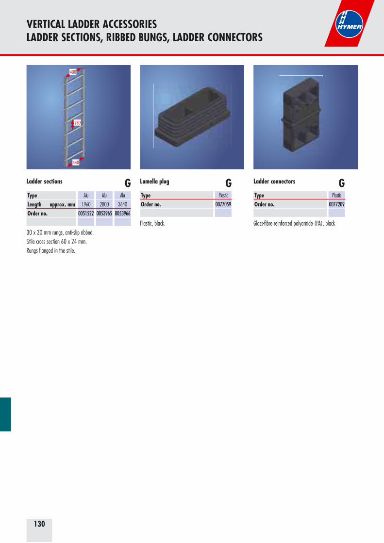
130
VERTICAL LADDER ACCESSORIES LADDER SECTIONS, RIBBED BUNGS, LADDER CONNECTORS
Plastic, black.
GTypeOrder no.
Plastic
0077059
Lamella plug
30 x 30 mm rungs, anti-slip ribbed.Stile cross section 60 x 24 mm. Rungs flanged in the stile.
TypeLength approx. mmOrder no.
Alu
1960
0051522
Alu
2800
0053965
Alu
3640
0053966
Ladder sections
448
280
400
Glass-fibre reinforced polyamide (PA), black
GTypeOrder no.
Plastic
0077209
Ladder connectorsG
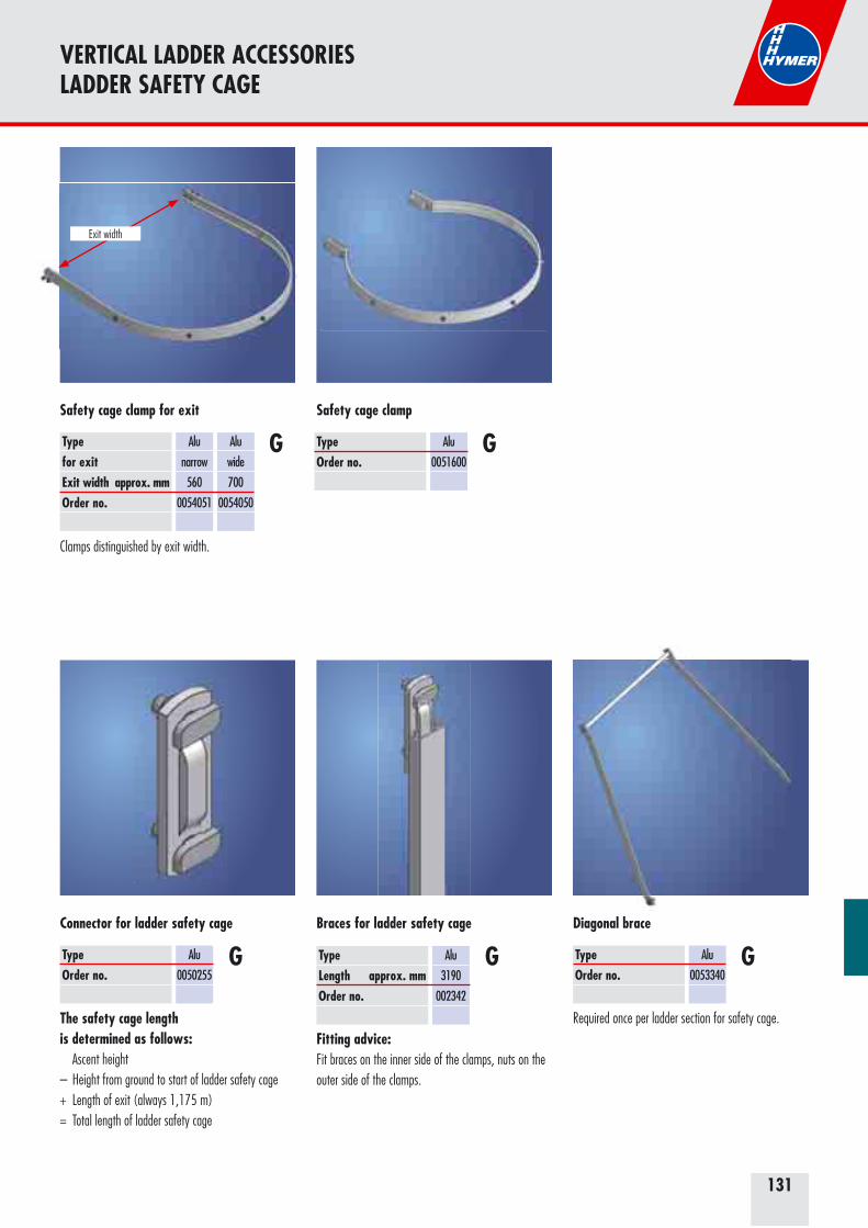
131
VERTICAL LADDER ACCESSORIESLADDER SAFETY CAGE
GTypeOrder no.
Alu
0050255
Connector for ladder safety cage
The safety cage length is determined as follows: Ascent height– Height from ground to start of ladder safety cage+ Length of exit (always 1,175 m)= Total length of ladder safety cage
GTypeOrder no.
Alu
0051600
Safety cage clamp
Required once per ladder section for safety cage.
GTypeOrder no.
Alu
0053340
Diagonal brace
Fitting advice:Fit braces on the inner side of the clamps, nuts on the outer side of the clamps.
TypeLength approx. mm Order no.
Alu
3190
002342
Braces for ladder safety cage
G
Clamps distinguished by exit width.
GTypefor exitExit width approx. mmOrder no.
Alu
narrow
560
0054051
Alu
wide
700
0054050
Safety cage clamp for exit
Exit width
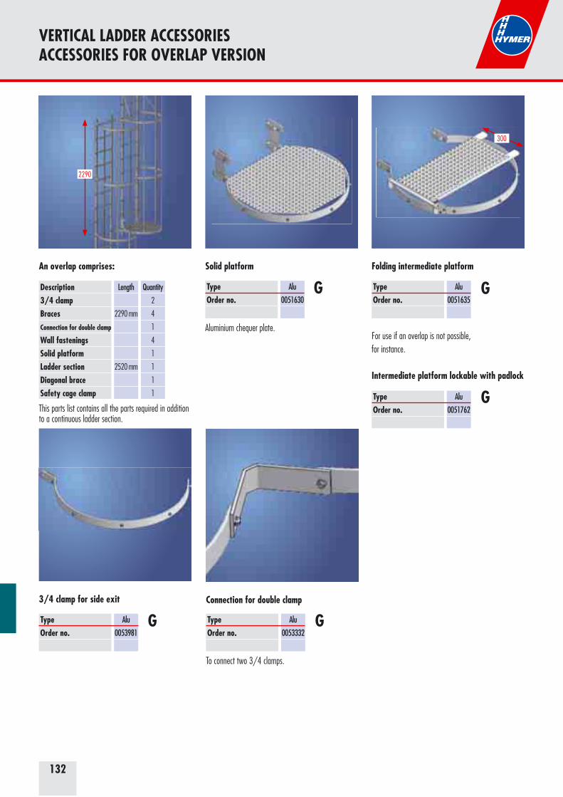
132
Solid platform
GTypeOrder no.
Alu
0051630
For use if an overlap is not possible, for instance.
Folding intermediate platform
GTypeOrder no.
Alu
0051635
300
GTypeOrder no.
Alu
0053981
3/4 clamp for side exit
To connect two 3/4 clamps.
GTypeOrder no.
Alu
0053332
Connection for double clamp
Description3/4 clampBracesConnection for double clamp
Wall fasteningsSolid platformLadder sectionDiagonal braceSafety cage clamp
Length
2290 mm
2520 mm
Quantity
2
4
1
4
1
1
1
1
An overlap comprises:
2290
This parts list contains all the parts required in addition to a continuous ladder section.
VERTICAL LADDER ACCESSORIESACCESSORIES FOR OVERLAP VERSION
Intermediate platform lockable with padlock
TypeOrder no.
Alu
0051762G
Aluminium chequer plate.
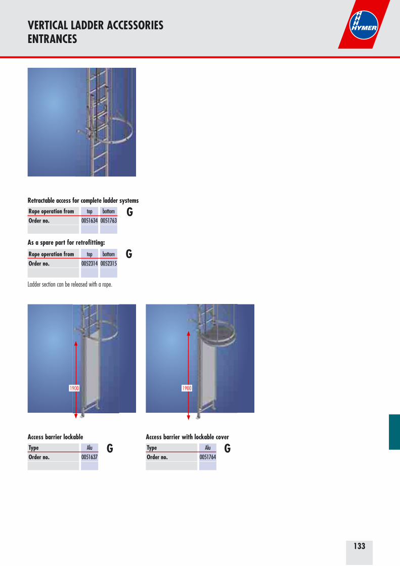
133
VERTICAL LADDER ACCESSORIES ENTRANCES
Access barrier lockable
GTypeOrder no.
Alu
0051637
1900
Access barrier with lockable cover
GTypeOrder no.
Alu
0051764
1900
Retractable access for complete ladder systems
GRope operation from Order no.
top
0051634
bottom
0051763
Rope operation from Order no.
top
0052314
bottom
0052315
As a spare part for retrofitting:
G
Ladder section can be released with a rope.

134
VERTICAL LADDER ACCESSORIESEXITS
DIN 18799-1 Structures: order additional exit step (order no. 0054038).DIN 14094 Escape ladders.
560 (700)
1180
TypeOrder no.
Alu
0053291
Alu widened
0053292
Straight exit
G
DIN 18799-1 Structures: order additional exit step (order no. 0054038).DIN 14094 Escape ladders.
1180
560
517
403
400
TypeOrder no.
Alu
0054054
Narrow exit with handrail
G
DIN 18799-1 Structures.DIN 14094 Escape ladders.
700 Länge
1180
687
400
TypeLength approx. mmOrder no.
Alu
725
0054056
Alu
950
0054057
Alu
1175
0054058
Exit with bridge
G
EN ISO 14122-4Access to plant and equipment.DIN 18799-1 Structures.DIN 14094 Escape ladders.
TypeLength approx. mmOrder no.
Alu
725
0054059
Alu
950
0054060
Alu
1175
0054061
Exit with bridge
G
700
1180
400
687
EN ISO 14122-4Access to plant and equipment.DIN 18799-1 Structures.DIN 14094 Escape ladders.
1180
700
400
150
TypeOrder no.
Alu
0053298
Wide straight exit
G
EN ISO 14122-4Access to plant and equipment.DIN 18799-1 Structures.DIN 14094 Escape ladders.
1180
700
403150
400
TypeOrder no.
Alu
0054055
Wide exit with handrail
G
134
BarrierBarrier
Guardrail
Exit step
Barrier
Guardrail
Exit step
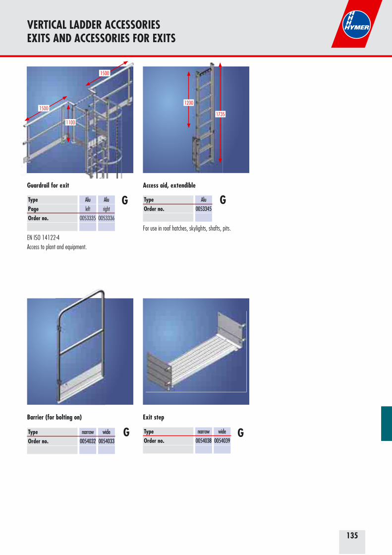
135
VERTICAL LADDER ACCESSORIESEXITS AND ACCESSORIES FOR EXITS
EN ISO 14122-4Access to plant and equipment.
TypePageOrder no.
Alu
left
0053335
Alu
right
0053336
Guardrail for exit
G
1500
1500
1100
TypeOrder no.
narrow
0054032
wide
0054033
Barrier (for bolting on)
G TypeOrder no.
narrow
0054038
wide
0054039
Exit step
G
For use in roof hatches, skylights, shafts, pits.
TypeOrder no.
Alu
0053345
Access aid, extendible
G
1735
1200

136
VERTICAL LADDER ACCESSORIESPLATFORMS
Platform with guardrail, small
GTypeOrder no.
Steel
0054040
800800
1100
Platform with guardrail, large
GTypeOrder no.
Steel
0054041
10001000
Extension platform with guardrail, small
GTypeOrder no.
Steel
0054042
800800
Extension platform with guardrail, large
GTypeOrder no.
Steel
0054043
1100
8001000
Galvanized steel grating platform.Galvanized steel guardrail.Width 800 mm, depth 800 mm.Can be used for all current standards.
Galvanized steel grating platform.Galvanized steel guardrail.Width 1,000 mm, depth 1,000 mm.Can be used for all current standards.
1100
Galvanized steel grating platform.Galvanized steel guardrail.Width 800 mm, depth 800 mm.Can be used for all current standards.
Galvanized steel grating platform.Galvanized steel guardrail.Width 800 mm, depth 1,000 mm.Can be used for all current standards.
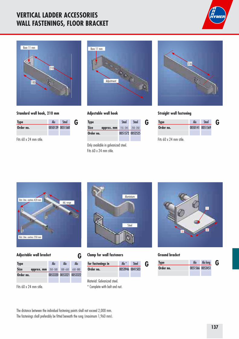
137
The distance between the individual fastening points shall not exceed 2,000 mm.The fastenings shall preferably be fitted beneath the rung (maximum 1,960 mm).
Fits 60 x 24 mm stile.
TypeOrder no.
Alu
0050139
Steel
0051568
Standard wall hook, 210 mm
G
180
210
Bore 11 mm
Only available in galvanized steel.Fits 60 x 24 mm stile.
TypeSize approx. mmOrder no.
Steel
155 - 245
0051572
Steel
250 - 350
0052525
Adjustable wall hook
G
Adjustment
Bore 11 mm
Fits 60 x 24 mm stile.
TypeOrder no.
Alu
0050141
Steel
0051569
Straight wall fastening
G
236
Material: Galvanized steel.* Complete with bolt and nut.
VERTICAL LADDER ACCESSORIESWALL FASTENINGS, FLOOR BRACKET
Fits 60 x 24 mm stile.
TypeSize approx. mmOrder no.
Alu
350 - 500
0053320
Alu
500 - 650
0053321
Alu
650 - 880
0053322
Adjustable wall bracket GTypeOrder no.
Ground bracket
GAlu
0051566
Alu long
0053451
6050
11
Adj. rangeDist. btw. centres 420 mm
Dist. btw. centres 250 mm
Gfor fastenings inOrder no.
Alu *
0053946
Clamp for wall fasteners
Steel
0041503
Aluminium
Steel
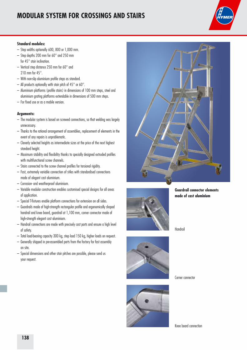
138
MODULAR SYSTEM FOR CROSSINGS AND STAIRS
Standard modules:– Step widths optionally 600, 800 or 1,000 mm.– Step depths 200 mm for 60° and 250 mm for 45° stair inclination.– Vertical step distance 250 mm for 60° and 210 mm for 45°.– With non-slip aluminium profile steps as standard.– All products optionally with stair pitch of 45° or 60°.– Aluminium platforms (profile stairs) in dimensions of 100 mm steps, steel and aluminium grating platforms extendable in dimensions of 500 mm steps.– For fixed use or as a mobile version.
Arguments:– The modular system is based on screwed connections, so that welding was largely unnecessary.– Thanks to the rational arrangement of assemblies, replacement of elements in the event of any repairs is unproblematic.– Cleverly selected heights as intermediate sizes at the price of the next highest standard height.– Maximum stability and flexibility thanks to specially designed extruded profiles with multifunctional screw channels.– Stairs connected to the screw channel profiles for torsional rigidity.– Fast, extremely variable connection of stiles with standardised connections made of elegant cast aluminium.– Corrosion- and weatherproof aluminium.– Variable modular construction enables customised special designs for all areas of application.– Special T-fixtures enable platform connections for extension on all sides.– Guardrails made of high-strength rectangular profile and ergonomically shaped handrail and knee board, guardrail at 1,100 mm, corner connector made of high-strength elegant cast aluminium.– Handrail connections are made with precisely cast parts and ensure a high level of safety.– Total load-bearing capacity 300 kg, step load 150 kg, higher loads on request.– Generally shipped in pre-assembled parts from the factory for fast assembly on site.– Special dimensions and other stair pitches are possible, please send us your request.
Handrail
Corner connector
Knee board connection
Guardrail connector elements made of cast aluminium
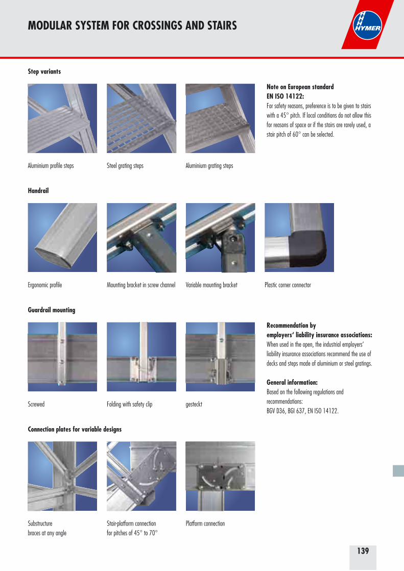
139
MODULAR SYSTEM FOR CROSSINGS AND STAIRS
Aluminium profile steps Steel grating steps Aluminium grating steps
Ergonomic profile Mounting bracket in screw channel Variable mounting bracket Plastic corner connector
Screwed Folding with safety clip gesteckt
Substructurebraces at any angle
Stair-platform connectionfor pitches of 45° to 70°
Platform connection
Step variants
Handrail
Guardrail mounting
Connection plates for variable designs
Note on European standardEN ISO 14122:For safety reasons, preference is to be given to stairs with a 45° pitch. If local conditions do not allow this for reasons of space or if the stairs are rarely used, a stair pitch of 60° can be selected.
Recommendation by employers‘ liability insurance associations:When used in the open, the industrial employers‘ liability insurance associations recommend the use of decks and steps made of aluminium or steel gratings.
General information:Based on the following regulations andrecommendations: BGV D36, BGI 637, EN ISO 14122.

140
The HYMER modular system One system – many solid, fast solutions
The Hymer modular system offers all partners the capability of meeting meet their requirements for individual solutions in ladder technology in a cost-effective, compact and fast way. Fixed stairs, mobile stairs with a platform or bridging stairs can be produced with the Hymer modular system in a very short time.
The following solutions are available:
Fast, time-saving product configuration with special online software.
Ask your HYMER consultant for further information.
Customised solutions possible on request
[email protected] +49 7522 700385
45° – 60°
45° – 60°
45° – 60°
MODULAR SYSTEM FOR CROSSINGS AND STAIRS
Fixed stairs: – From 45° – 60° stair pitch.– Handrail one side/both sides. – Step width 600, 800, 1,000 mm.– Different height variants possible.
Stairs with a platform: – From 45° – 60° stair pitch.– Handrail one side/both sides. – Step width 600, 800, 1,000 mm.– Platform length 500 – 2,500 mm (beyond this, additional support must be planned depending on the height and length of the platform). – Different height variants possible.
Fixed bridging stairs– From 45° – 60° stair pitch– Handrail one side/both sides – Step width 600, 800, 1,000 mm– Bridge length 500 – 2,500 mm (beyond this, additional support must be planned depending on the height and length of the bridging section). – Different height variants possible.
H max
H min
L maxL min
H max
H min
L max
H max
H min
L max
LW max
L max
L min
L min
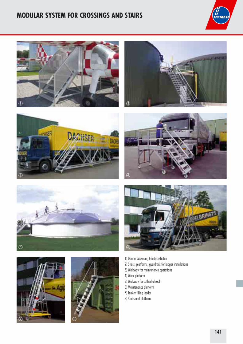
141
MODULAR SYSTEM FOR CROSSINGS AND STAIRS
� �
��
��
�
1) Dornier Museum, Friedrichshafen2) Stairs, platforms, guardrails for biogas installations3) Walkway for maintenance operations4) Work platform5) Walkway for cathedral roof6) Maintenance platform7) Tanker filling ladder8) Stairs and platform
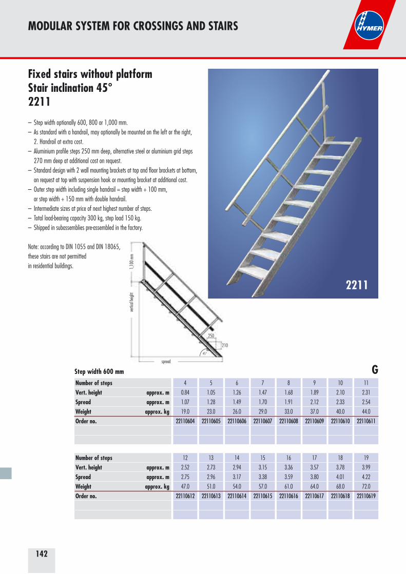
142
210
250
spread
vertic
al he
ight
1,10
0 mm
45°
MODULAR SYSTEM FOR CROSSINGS AND STAIRS
2211
Fixed stairs without platform Stair inclination 45°2211
– Step width optionally 600, 800 or 1,000 mm.– As standard with a handrail, may optionally be mounted on the left or the right, 2. Handrail at extra cost.– Aluminium profile steps 250 mm deep, alternative steel or aluminium grid steps 270 mm deep at additional cost on request.– Standard design with 2 wall mounting brackets at top and floor brackets at bottom, on request at top with suspension hook or mounting bracket at additional cost.– Outer step width including single handrail = step width + 100 mm, or step width + 150 mm with double handrail.– Intermediate sizes at price of next highest number of steps.– Total load-bearing capacity 300 kg, step load 150 kg.– Shipped in subassemblies pre-assembled in the factory.
Note: according to DIN 1055 and DIN 18065, these stairs are not permitted in residential buildings.
Number of stepsVert. height approx. mSpread approx. mWeight approx. kgOrder no.
4
0.84
1.07
19.0
22110604
5
1.05
1.28
23.0
22110605
6
1.26
1.49
26.0
22110606
7
1.47
1.70
29.0
22110607
8
1.68
1.91
33.0
22110608
9
1.89
2.12
37.0
22110609
10
2.10
2.33
40.0
22110610
11
2.31
2.54
44.0
22110611
Step width 600 mm
Number of stepsVert. height approx. mSpread approx. mWeight approx. kgOrder no.
12
2.52
2.75
47.0
22110612
13
2.73
2.96
51.0
22110613
14
2.94
3.17
54.0
22110614
15
3.15
3.38
57.0
22110615
16
3.36
3.59
61.0
22110616
17
3.57
3.80
64.0
22110617
18
3.78
4.01
68.0
22110618
19
3.99
4.22
72.0
22110619
G
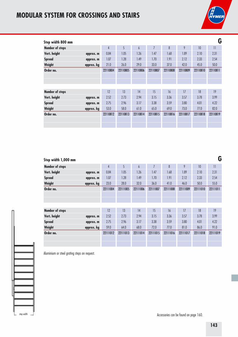
143
MODULAR SYSTEM FOR CROSSINGS AND STAIRS
Number of stepsVert. height approx. mSpread approx. mWeight approx. kgOrder no.
4
0.84
1.07
21.0
22110804
5
1.05
1.28
26.0
22110805
6
1.26
1.49
29.0
22110806
7
1.47
1.70
33.0
22110807
8
1.68
1.91
37.0
22110808
9
1.89
2.12
42.0
22110809
10
2.10
2.33
45.0
22110810
11
2.31
2.54
50.0
22110811
Step width 800 mm
Number of stepsVert. height approx. mSpread approx. mWeight approx. kgOrder no.
12
2.52
2.75
53.0
22110812
13
2.73
2.96
58.0
22110813
14
2.94
3.17
61.0
22110814
15
3.15
3.38
65.0
22110815
16
3.36
3.59
69.0
22110816
17
3.57
3.80
73.0
22110817
18
3.78
4.01
77.0
22110818
19
3.99
4.22
82.0
22110819
Number of stepsVert. height approx. mSpread approx. mWeight approx. kgOrder no.
4
0.84
1.07
23.0
22111004
5
1.05
1.28
28.0
22111005
6
1.26
1.49
32.0
22111006
7
1.47
1.70
36.0
22111007
8
1.68
1.91
41.0
22111008
9
1.89
2.12
46.0
22111009
10
2.10
2.33
50.0
22111010
11
2.31
2.54
55.0
22111011
Step width 1,000 mm
Number of stepsVert. height approx. mSpread approx. mWeight approx. kgOrder no.
12
2.52
2.75
59.0
22111012
13
2.73
2.96
64.0
22111013
14
2.94
3.17
68.0
22111014
15
3.15
3.38
72.0
22111015
16
3.36
3.59
77.0
22111016
17
3.57
3.80
81.0
22111017
18
3.78
4.01
86.0
22111018
19
3.99
4.22
91.0
22111019
G
G
step width Accessories can be found on page 160.
Aluminium or steel grating steps on request.
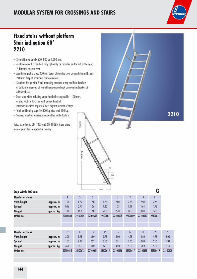
144
spread
verti
cal h
eight
1,10
0 mm
200
250
60°
MODULAR SYSTEM FOR CROSSINGS AND STAIRS
2210
Fixed stairs without platform Stair inclination 60°2210
– Step width optionally 600, 800 or 1,000 mm.– As standard with a handrail, may optionally be mounted on the left or the right, 2. Handrail at extra cost.– Aluminium profile steps 200 mm deep, alternative steel or aluminium grid steps 240 mm deep at additional cost on request.– Standard design with 2 wall mounting brackets at top and floor brackets at bottom, on request at top with suspension hook or mounting bracket at additional cost.– Outer step width including single handrail = step width + 100 mm, or step width + 150 mm with double handrail.– Intermediate sizes at price of next highest number of steps.– Total load-bearing capacity 300 kg, step load 150 kg.– Shipped in subassemblies pre-assembled in the factory.
Note: according to DIN 1055 and DIN 18065, these stairs are not permitted in residential buildings.
Number of stepsVert. height approx. mSpread approx. mWeight approx. kgOrder no.
4
1.00
0.76
13.0
22100604
5
1.25
0.91
16.0
22100605
6
1.50
1.06
19.0
22100606
7
1.75
1.20
22.0
22100607
8
2.00
1.35
25.0
22100608
9
2.25
1.49
28.0
22100609
10
2.50
1.64
31.0
22100610
11
2.75
1.78
34.0
22100611
12
3.00
1.93
36.0
22100612
Step width 600 mm
Number of stepsVert. height approx. mSpread approx. mWeight approx. kgOrder no.
13
3.25
2.07
39.0
22100613
14
3.50
2.22
43.0
22100614
15
3.75
2.36
46.0
22100615
16
4.00
2.51
48.0
22100616
17
4.25
2.65
51.0
22100617
18
4.50
2.80
54.0
22100618
19
4.75
2.95
57.0
22100619
20
5.00
3.09
60.0
22100620
G
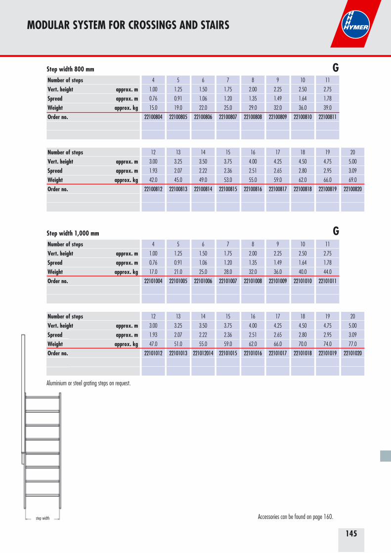
145
MODULAR SYSTEM FOR CROSSINGS AND STAIRS
Number of stepsVert. height approx. mSpread approx. mWeight approx. kgOrder no.
4
1.00
0.76
15.0
22100804
5
1.25
0.91
19.0
22100805
6
1.50
1.06
22.0
22100806
7
1.75
1.20
25.0
22100807
8
2.00
1.35
29.0
22100808
9
2.25
1.49
32.0
22100809
10
2.50
1.64
36.0
22100810
11
2.75
1.78
39.0
22100811
Step width 800 mm
Number of stepsVert. height approx. mSpread approx. mWeight approx. kgOrder no.
12
3.00
1.93
42.0
22100812
13
3.25
2.07
45.0
22100813
14
3.50
2.22
49.0
22100814
15
3.75
2.36
53.0
22100815
16
4.00
2.51
55.0
22100816
17
4.25
2.65
59.0
22100817
18
4.50
2.80
62.0
22100818
19
4.75
2.95
66.0
22100819
20
5.00
3.09
69.0
22100820
Number of stepsVert. height approx. mSpread approx. mWeight approx. kgOrder no.
4
1.00
0.76
17.0
22101004
5
1.25
0.91
21.0
22101005
6
1.50
1.06
25.0
22101006
7
1.75
1.20
28.0
22101007
8
2.00
1.35
32.0
22101008
9
2.25
1.49
36.0
22101009
10
2.50
1.64
40.0
22101010
11
2.75
1.78
44.0
22101011
Step width 1,000 mm
Number of stepsVert. height approx. mSpread approx. mWeight approx. kgOrder no.
12
3.00
1.93
47.0
22101012
13
3.25
2.07
51.0
22101013
14
3.50
2.22
55.0
221012014
15
3.75
2.36
59.0
22101015
16
4.00
2.51
62.0
22101016
17
4.25
2.65
66.0
22101017
18
4.50
2.80
70.0
22101018
19
4.75
2.95
74.0
22101019
20
5.00
3.09
77.0
22101020
Spread Weight Order no.
G
G
step width Accessories can be found on page 160.
Aluminium or steel grating steps on request.
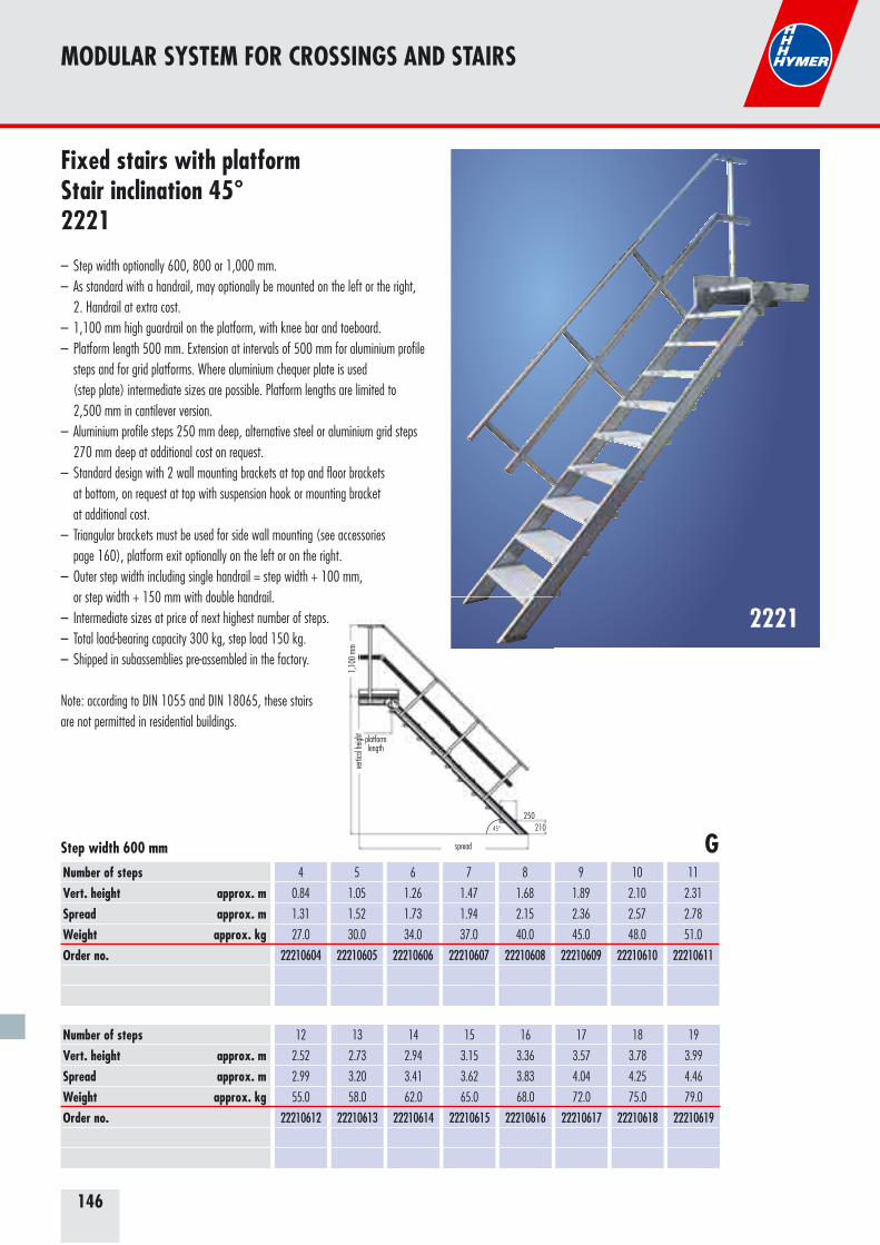
146
MODULAR SYSTEM FOR CROSSINGS AND STAIRS
2221
Fixed stairs with platform Stair inclination 45°2221
– Step width optionally 600, 800 or 1,000 mm.– As standard with a handrail, may optionally be mounted on the left or the right, 2. Handrail at extra cost.– 1,100 mm high guardrail on the platform, with knee bar and toeboard.– Platform length 500 mm. Extension at intervals of 500 mm for aluminium profile steps and for grid platforms. Where aluminium chequer plate is used (step plate) intermediate sizes are possible. Platform lengths are limited to 2,500 mm in cantilever version.– Aluminium profile steps 250 mm deep, alternative steel or aluminium grid steps 270 mm deep at additional cost on request.– Standard design with 2 wall mounting brackets at top and floor brackets at bottom, on request at top with suspension hook or mounting bracket at additional cost.– Triangular brackets must be used for side wall mounting (see accessories
page 160), platform exit optionally on the left or on the right.– Outer step width including single handrail = step width + 100 mm, or step width + 150 mm with double handrail.– Intermediate sizes at price of next highest number of steps.– Total load-bearing capacity 300 kg, step load 150 kg.– Shipped in subassemblies pre-assembled in the factory.
Note: according to DIN 1055 and DIN 18065, these stairs are not permitted in residential buildings.
Number of stepsVert. height approx. mSpread approx. mWeight approx. kgOrder no.
4
0.84
1.31
27.0
22210604
5
1.05
1.52
30.0
22210605
6
1.26
1.73
34.0
22210606
7
1.47
1.94
37.0
22210607
8
1.68
2.15
40.0
22210608
9
1.89
2.36
45.0
22210609
10
2.10
2.57
48.0
22210610
11
2.31
2.78
51.0
22210611
12
2.52
2.99
55.0
22210612
Step width 600 mm
Number of stepsVert. height approx. mSpread approx. mWeight approx. kgOrder no.
13
2.73
3.20
58.0
22210613
14
2.94
3.41
62.0
22210614
15
3.15
3.62
65.0
22210615
16
3.36
3.83
68.0
22210616
17
3.57
4.04
72.0
22210617
18
3.78
4.25
75.0
22210618
19
3.99
4.46
79.0
22210619
G250
spread
vertic
al he
ight
platform length
1,10
0 mm
21045°
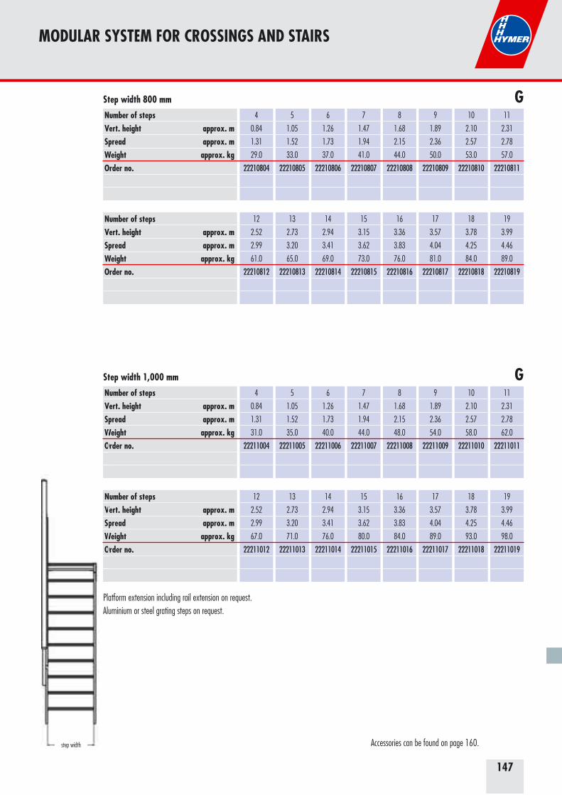
147
MODULAR SYSTEM FOR CROSSINGS AND STAIRS
Number of stepsVert. height approx. mSpread approx. mWeight approx. kgOrder no.
12
2.52
2.99
61.0
22210812
13
2.73
3.20
65.0
22210813
14
2.94
3.41
69.0
22210814
15
3.15
3.62
73.0
22210815
16
3.36
3.83
76.0
22210816
17
3.57
4.04
81.0
22210817
18
3.78
4.25
84.0
22210818
19
3.99
4.46
89.0
22210819
Step width 800 mm
Number of stepsVert. height approx. mSpread approx. mWeight approx. kgOrder no.
4
0.84
1.31
29.0
22210804
5
1.05
1.52
33.0
22210805
6
1.26
1.73
37.0
22210806
7
1.47
1.94
41.0
22210807
8
1.68
2.15
44.0
22210808
9
1.89
2.36
50.0
22210809
10
2.10
2.57
53.0
22210810
11
2.31
2.78
57.0
22210811
Number of stepsVert. height approx. mSpread approx. mWeight approx. kgOrder no.
4
0.84
1.31
31.0
22211004
5
1.05
1.52
35.0
22211005
6
1.26
1.73
40.0
22211006
7
1.47
1.94
44.0
22211007
8
1.68
2.15
48.0
22211008
9
1.89
2.36
54.0
22211009
10
2.10
2.57
58.0
22211010
11
2.31
2.78
62.0
22211011
Step width 1,000 mm
Number of stepsVert. height approx. mSpread approx. mWeight approx. kgOrder no.
12
2.52
2.99
67.0
22211012
13
2.73
3.20
71.0
22211013
14
2.94
3.41
76.0
22211014
15
3.15
3.62
80.0
22211015
16
3.36
3.83
84.0
22211016
17
3.57
4.04
89.0
22211017
18
3.78
4.25
93.0
22211018
19
3.99
4.46
98.0
22211019
WO
NVSWO
G
G
step width Accessories can be found on page 160.
Platform extension including rail extension on request.Aluminium or steel grating steps on request.
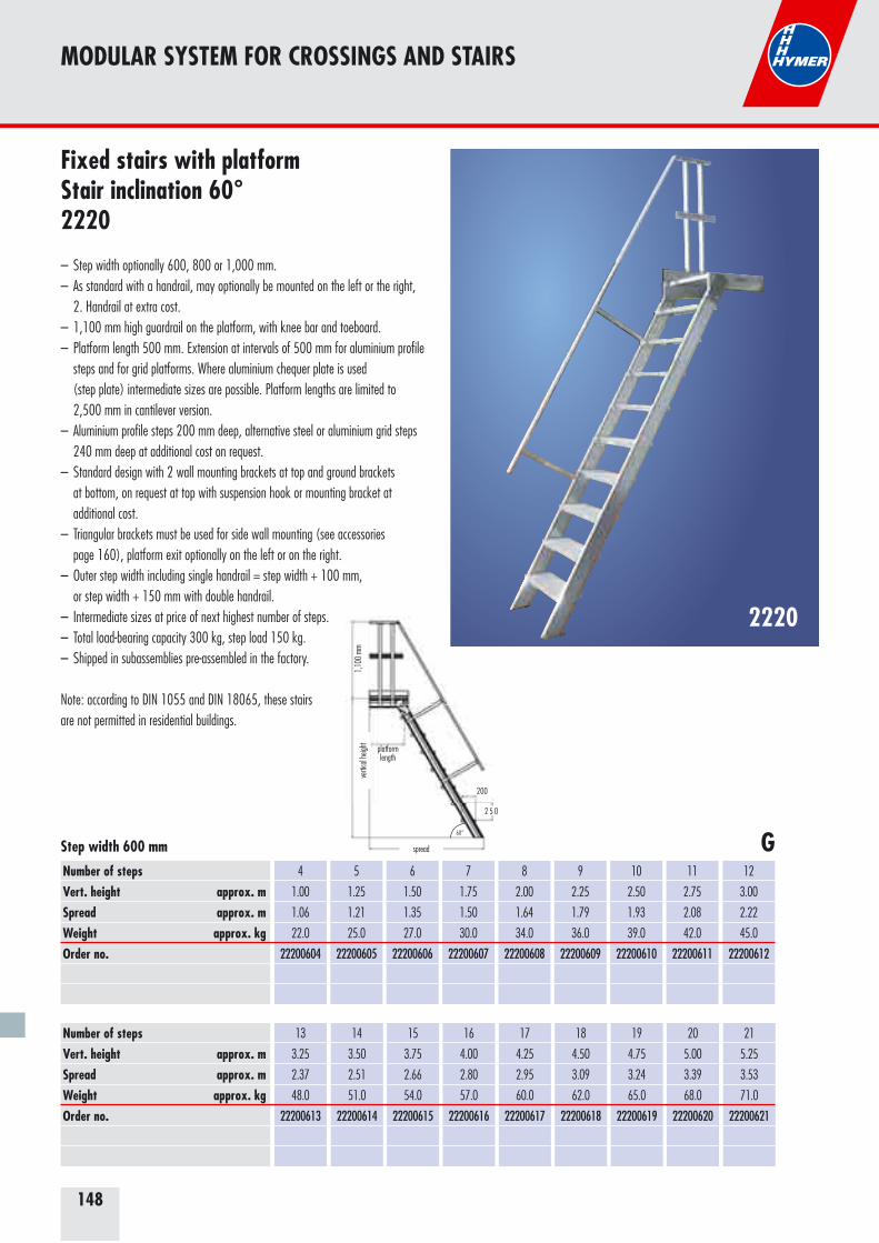
148
200
spread
vertic
al he
ight
1,10
0 mm
platformlength
2 5 0
60°
2220
Fixed stairs with platform Stair inclination 60°2220
– Step width optionally 600, 800 or 1,000 mm.– As standard with a handrail, may optionally be mounted on the left or the right, 2. Handrail at extra cost.– 1,100 mm high guardrail on the platform, with knee bar and toeboard.– Platform length 500 mm. Extension at intervals of 500 mm for aluminium profile steps and for grid platforms. Where aluminium chequer plate is used (step plate) intermediate sizes are possible. Platform lengths are limited to 2,500 mm in cantilever version.– Aluminium profile steps 200 mm deep, alternative steel or aluminium grid steps 240 mm deep at additional cost on request.– Standard design with 2 wall mounting brackets at top and ground brackets at bottom, on request at top with suspension hook or mounting bracket at additional cost.– Triangular brackets must be used for side wall mounting (see accessories
page 160), platform exit optionally on the left or on the right.– Outer step width including single handrail = step width + 100 mm, or step width + 150 mm with double handrail.– Intermediate sizes at price of next highest number of steps.– Total load-bearing capacity 300 kg, step load 150 kg.– Shipped in subassemblies pre-assembled in the factory.
Note: according to DIN 1055 and DIN 18065, these stairs are not permitted in residential buildings.
Number of stepsVert. height approx. mSpread approx. mWeight approx. kgOrder no.
4
1.00
1.06
22.0
22200604
5
1.25
1.21
25.0
22200605
6
1.50
1.35
27.0
22200606
7
1.75
1.50
30.0
22200607
8
2.00
1.64
34.0
22200608
9
2.25
1.79
36.0
22200609
10
2.50
1.93
39.0
22200610
11
2.75
2.08
42.0
22200611
12
3.00
2.22
45.0
22200612
13
3.25
2.37
48.0
22200613
Step width 600 mm
Number of stepsVert. height approx. mSpread approx. mWeight approx. kgOrder no.
14
3.50
2.51
51.0
22200614
15
3.75
2.66
54.0
22200615
16
4.00
2.80
57.0
22200616
17
4.25
2.95
60.0
22200617
18
4.50
3.09
62.0
22200618
19
4.75
3.24
65.0
22200619
20
5.00
3.39
68.0
22200620
21
5.25
3.53
71.0
22200621
G
MODULAR SYSTEM FOR CROSSINGS AND STAIRS
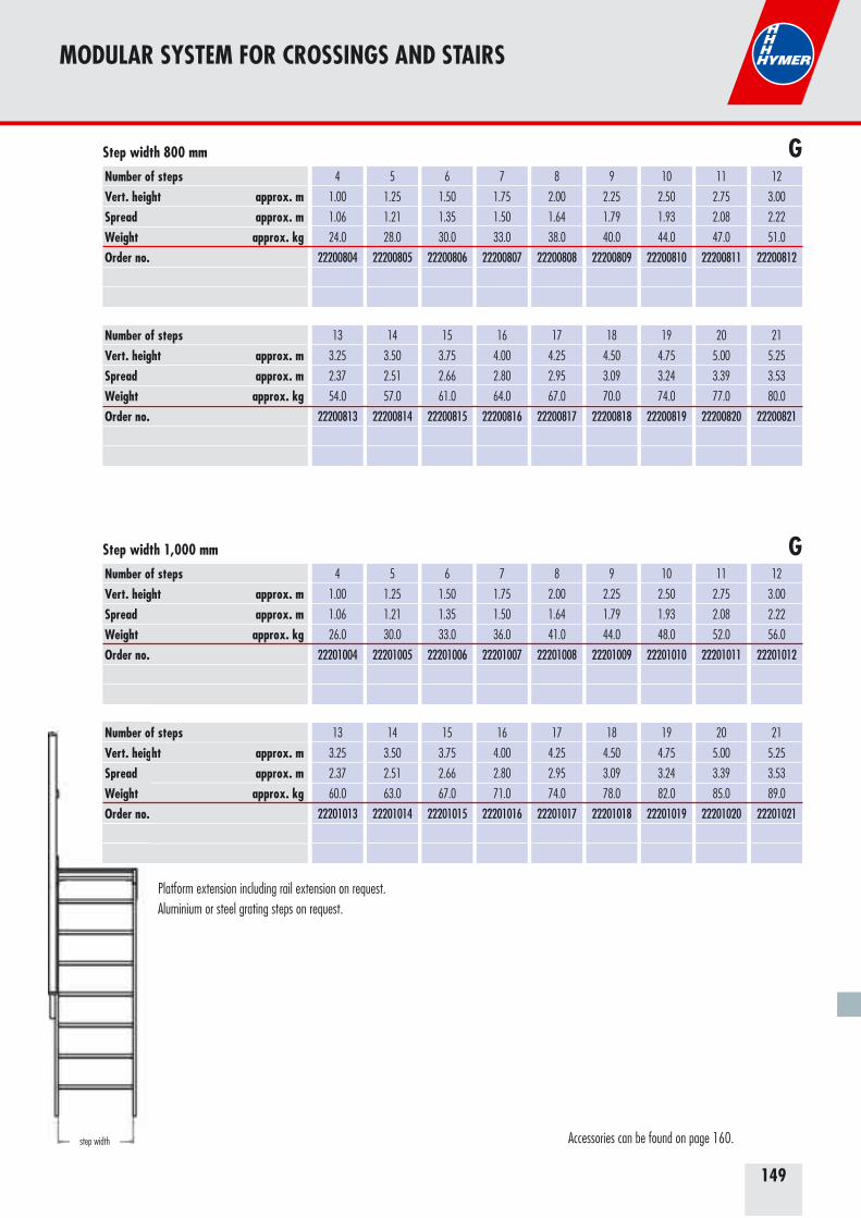
149
Number of stepsVert. height approx. mSpread approx. mWeight approx. kgOrder no.
13
3.25
2.37
54.0
22200813
14
3.50
2.51
57.0
22200814
15
3.75
2.66
61.0
22200815
16
4.00
2.80
64.0
22200816
17
4.25
2.95
67.0
22200817
18
4.50
3.09
70.0
22200818
19
4.75
3.24
74.0
22200819
20
5.00
3.39
77.0
22200820
21
5.25
3.53
80.0
22200821
Step width 800 mm
Number of stepsVert. height approx. mSpread approx. mWeight approx. kgOrder no.
4
1.00
1.06
24.0
22200804
5
1.25
1.21
28.0
22200805
6
1.50
1.35
30.0
22200806
7
1.75
1.50
33.0
22200807
8
2.00
1.64
38.0
22200808
9
2.25
1.79
40.0
22200809
10
2.50
1.93
44.0
22200810
11
2.75
2.08
47.0
22200811
12
3.00
2.22
51.0
22200812
Number of stepsVert. height approx. mSpread approx. mWeight approx. kgOrder no.
4
1.00
1.06
26.0
22201004
5
1.25
1.21
30.0
22201005
6
1.50
1.35
33.0
22201006
7
1.75
1.50
36.0
22201007
8
2.00
1.64
41.0
22201008
9
2.25
1.79
44.0
22201009
10
2.50
1.93
48.0
22201010
11
2.75
2.08
52.0
22201011
12
3.00
2.22
56.0
22201012
Step width 1,000 mm
Number of stepsVert. height approx. mSpread approx. mWeight approx. kgOrder no.
13
3.25
2.37
60.0
22201013
14
3.50
2.51
63.0
22201014
15
3.75
2.66
67.0
22201015
16
4.00
2.80
71.0
22201016
17
4.25
2.95
74.0
22201017
18
4.50
3.09
78.0
22201018
19
4.75
3.24
82.0
22201019
20
5.00
3.39
85.0
22201020
21
5.25
3.53
89.0
22201021
Number oVert. heigSpread Weight Order no.
G
G
MODULAR SYSTEM FOR CROSSINGS AND STAIRS
step width Accessories can be found on page 160.
Platform extension including rail extension on request.Aluminium or steel grating steps on request.
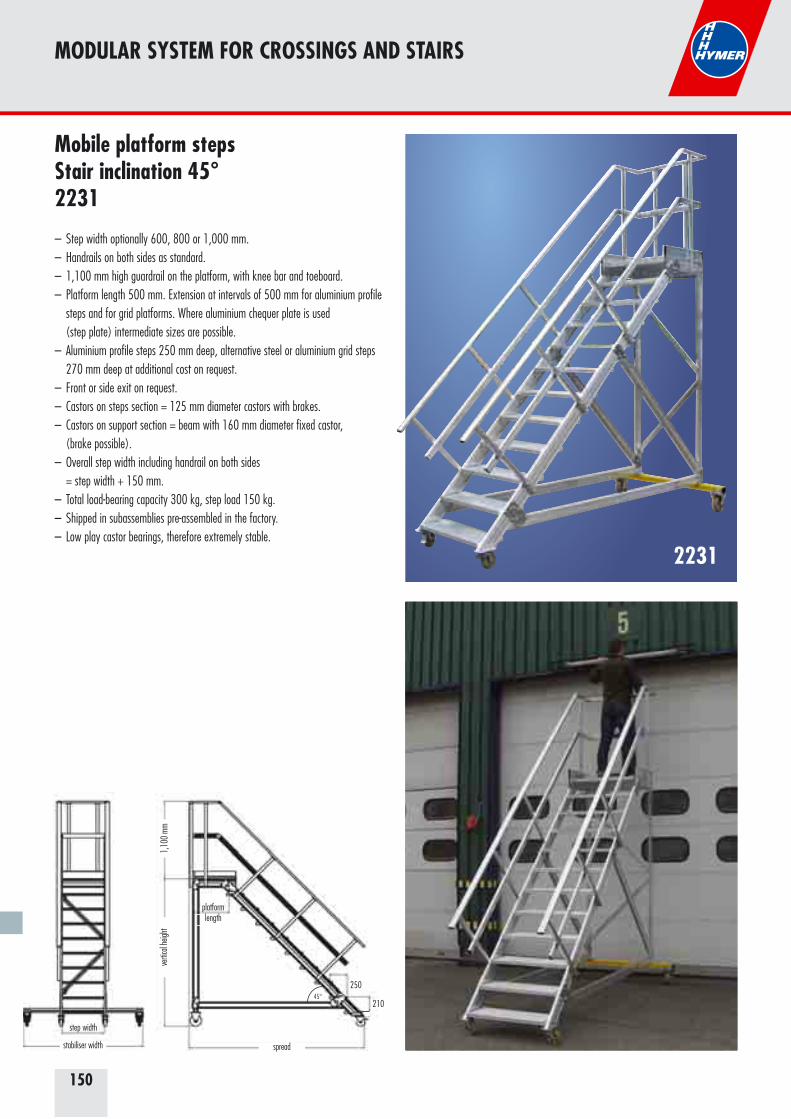
150
2231
Mobile platform steps Stair inclination 45°2231
– Step width optionally 600, 800 or 1,000 mm.– Handrails on both sides as standard.– 1,100 mm high guardrail on the platform, with knee bar and toeboard.– Platform length 500 mm. Extension at intervals of 500 mm for aluminium profile steps and for grid platforms. Where aluminium chequer plate is used (step plate) intermediate sizes are possible.– Aluminium profile steps 250 mm deep, alternative steel or aluminium grid steps 270 mm deep at additional cost on request.– Front or side exit on request.– Castors on steps section = 125 mm diameter castors with brakes.– Castors on support section = beam with 160 mm diameter fixed castor, (brake possible).– Overall step width including handrail on both sides
= step width + 150 mm.– Total load-bearing capacity 300 kg, step load 150 kg.– Shipped in subassemblies pre-assembled in the factory.– Low play castor bearings, therefore extremely stable.
MODULAR SYSTEM FOR CROSSINGS AND STAIRS
spread
vertic
al he
ight
1,10
0 mm
step width
platformlength
stabiliser width
45°210
250
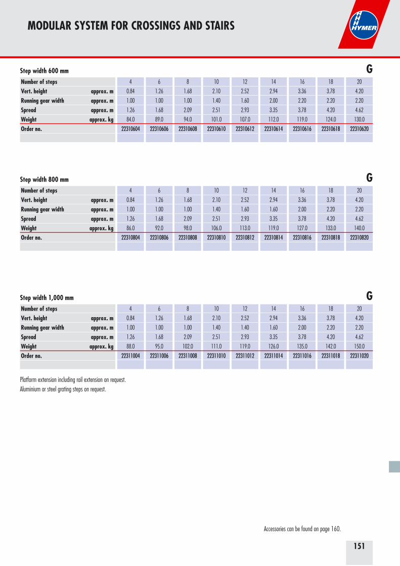
151
Number of stepsVert. height approx. mRunning gear width approx. mSpread approx. mWeight approx. kgOrder no.
4
0.84
1.00
1.26
84.0
22310604
6
1.26
1.00
1.68
89.0
22310606
8
1.68
1.00
2.09
94.0
22310608
10
2.10
1.40
2.51
101.0
22310610
12
2.52
1.60
2.93
107.0
22310612
14
2.94
2.00
3.35
112.0
22310614
16
3.36
2.20
3.78
119.0
22310616
18
3.78
2.20
4.20
124.0
22310618
20
4.20
2.20
4.62
130.0
22310620
Step width 600 mm
Number of stepsVert. height approx. mRunning gear width approx. mSpread approx. mWeight approx. kgOrder no.
4
0.84
1.00
1.26
88.0
22311004
6
1.26
1.00
1.68
95.0
22311006
8
1.68
1.00
2.09
102.0
22311008
10
2.10
1.40
2.51
111.0
22311010
12
2.52
1.40
2.93
119.0
22311012
14
2.94
1.60
3.35
126.0
22311014
16
3.36
2.00
3.78
135.0
22311016
18
3.78
2.20
4.20
142.0
22311018
20
4.20
2.20
4.62
150.0
22311020
Step width 1,000 mm
Number of stepsVert. height approx. mRunning gear width approx. mSpread approx. mWeight approx. kgOrder no.
4
0.84
1.00
1.26
86.0
22310804
6
1.26
1.00
1.68
92.0
22310806
8
1.68
1.00
2.09
98.0
22310808
10
2.10
1.40
2.51
106.0
22310810
12
2.52
1.60
2.93
113.0
22310812
14
2.94
1.60
3.35
119.0
22310814
16
3.36
2.00
3.78
127.0
22310816
18
3.78
2.20
4.20
133.0
22310818
20
4.20
2.20
4.62
140.0
22310820
Step width 800 mm G
G
G
MODULAR SYSTEM FOR CROSSINGS AND STAIRS
Accessories can be found on page 160.
Platform extension including rail extension on request.Aluminium or steel grating steps on request.
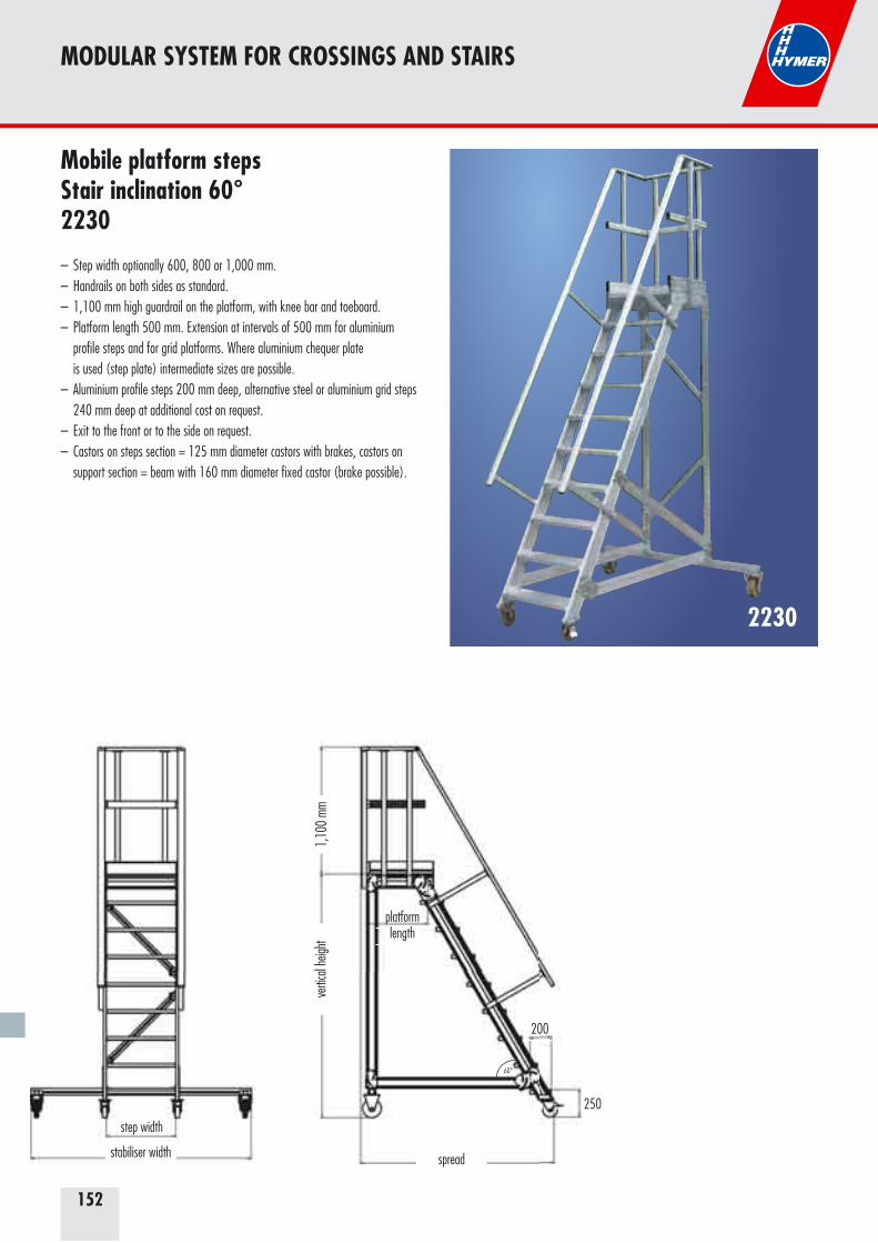
152
2230
Mobile platform steps Stair inclination 60°2230
– Step width optionally 600, 800 or 1,000 mm.– Handrails on both sides as standard.– 1,100 mm high guardrail on the platform, with knee bar and toeboard.– Platform length 500 mm. Extension at intervals of 500 mm for aluminium profile steps and for grid platforms. Where aluminium chequer plate is used (step plate) intermediate sizes are possible.– Aluminium profile steps 200 mm deep, alternative steel or aluminium grid steps 240 mm deep at additional cost on request.– Exit to the front or to the side on request.– Castors on steps section = 125 mm diameter castors with brakes, castors on support section = beam with 160 mm diameter fixed castor (brake possible).
MODULAR SYSTEM FOR CROSSINGS AND STAIRS
200
250
spread
vertic
al he
ight
1,10
0 mm
platformlength
step width
stabiliser width
60°
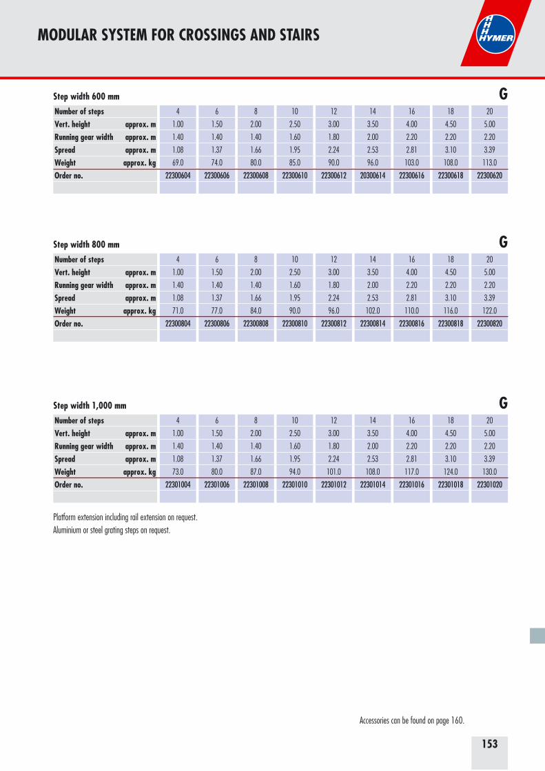
153
Number of stepsVert. height approx. mRunning gear width approx. mSpread approx. mWeight approx. kgOrder no.
4
1.00
1.40
1.08
69.0
22300604
6
1.50
1.40
1.37
74.0
22300606
8
2.00
1.40
1.66
80.0
22300608
10
2.50
1.60
1.95
85.0
22300610
12
3.00
1.80
2.24
90.0
22300612
14
3.50
2.00
2.53
96.0
20300614
16
4.00
2.20
2.81
103.0
22300616
18
4.50
2.20
3.10
108.0
22300618
20
5.00
2.20
3.39
113.0
22300620
Step width 600 mm
Number of stepsVert. height approx. mRunning gear width approx. mSpread approx. mWeight approx. kgOrder no.
4
1.00
1.40
1.08
73.0
22301004
6
1.50
1.40
1.37
80.0
22301006
8
2.00
1.40
1.66
87.0
22301008
10
2.50
1.60
1.95
94.0
22301010
12
3.00
1.80
2.24
101.0
22301012
14
3.50
2.00
2.53
108.0
22301014
16
4.00
2.20
2.81
117.0
22301016
18
4.50
2.20
3.10
124.0
22301018
20
5.00
2.20
3.39
130.0
22301020
Step width 1,000 mm
Number of stepsVert. height approx. mRunning gear width approx. mSpread approx. mWeight approx. kgOrder no.
4
1.00
1.40
1.08
71.0
22300804
6
1.50
1.40
1.37
77.0
22300806
8
2.00
1.40
1.66
84.0
22300808
10
2.50
1.60
1.95
90.0
22300810
12
3.00
1.80
2.24
96.0
22300812
14
3.50
2.00
2.53
102.0
22300814
16
4.00
2.20
2.81
110.0
22300816
18
4.50
2.20
3.10
116.0
22300818
20
5.00
2.20
3.39
122.0
22300820
Step width 800 mm G
G
G
MODULAR SYSTEM FOR CROSSINGS AND STAIRS
Accessories can be found on page 160.
Platform extension including rail extension on request.Aluminium or steel grating steps on request.
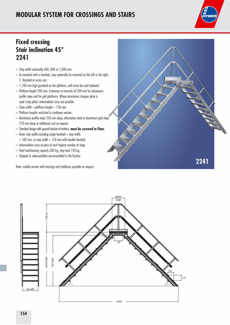
154
2241
Fixed crossing Stair inclination 45°2241
– Step width optionally 600, 800 or 1,000 mm.– As standard with a handrail, may optionally be mounted on the left or the right, 2. Handrail at extra cost.– 1,100 mm high guardrail on the platform, with knee bar and toeboard.– Platform length 500 mm. Extension at intervals of 500 mm for aluminium profile steps and for grid platforms. Where aluminium chequer plate is used (step plate) intermediate sizes are possible.– Clear width = platform length – 150 mm– Platform lengths restricted in cantilever version.– Aluminium profile steps 250 mm deep, alternative steel or aluminium grid steps 270 mm deep at additional cost on request.– Standard design with ground bracket at bottom, must be screwed to floor.– Outer step width including single handrail = step width + 100 mm, or step width + 150 mm with double handrail– Intermediate sizes at price of next highest number of steps– Total load-bearing capacity 300 kg, step load 150 kg.– Shipped in subassemblies pre-assembled in the factory.
Note: mobile version with bracings and stabilisers possible on request.
MODULAR SYSTEM FOR CROSSINGS AND STAIRS
210
250
spread
vertic
al he
ight
1,10
0 mm
platformlength
step width
clear
heigh
t
45°45°
250

155
Number of stepsVert. height approx. m Clear height approx. mSpread approx. mWeight approx. kgOrder no.
3
0.63
0.50
1.65
36.0
22410603
4
0.84
0.71
2.07
42.0
22410604
5
1.05
0.92
2.49
49.0
22410605
6
1.26
1.13
2.91
56.0
22410606
7
1.47
1.34
3.33
63.0
22410607
8
1.68
1.55
3.75
72.0
22410608
9
1.89
1.76
4.17
78.0
22410609
10
2.10
1.97
4.59
85.0
22410610
11
2.31
2.18
5.01
92.0
22410611
Step width 600 mm
Number of stepsVert. height approx. m Clear height approx. mSpread approx. mWeight approx. kgOrder no.
3
0.63
0.50
1.65
39.0
22411003
4
0.84
0.71
2.07
48.0
22411004
5
1.05
0.92
2.49
54.0
22411005
6
1.26
1.13
2.91
62.0
22411006
7
1.47
1.34
3.33
70.0
22411007
8
1.68
1.55
3.75
80.0
22411008
9
1.89
1.76
4.17
87.0
22411009
10
2.10
1.97
4.59
95.0
22411010
11
2.31
2.18
5.01
103.0
22411011
Step width 1,000 mm
Number of stepsVert. height approx. m Clear height approx. mSpread approx. mWeight approx. kgOrder no.
3
0.63
0.50
1.65
38.0
22410803
4
0.84
0.71
2.07
44.0
22410804
5
1.05
0.92
2.49
52.0
22410805
6
1.26
1.13
2.91
59.0
22410806
7
1.47
1.34
3.33
67.0
22410807
8
1.68
1.55
3.75
76.0
22410808
9
1.89
1.76
4.17
83.0
22410809
10
2.10
1.97
4.59
90.0
22410810
11
2.31
2.18
5.01
98.0
22410811
Step width 800 mm G
G
G
MODULAR SYSTEM FOR CROSSINGS AND STAIRS
Accessories can be found on page 160.
Platform extension including rail extension on request.Aluminium or steel grating steps on request.
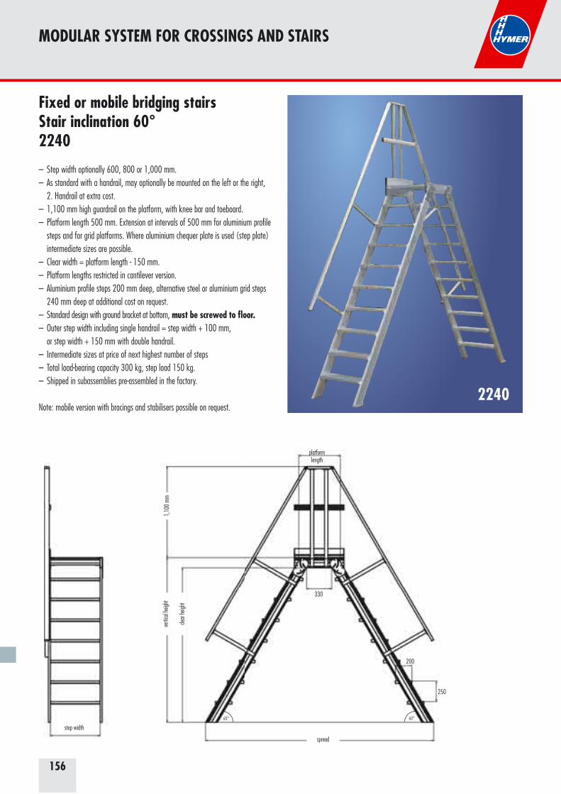
156
2240
Fixed or mobile bridging stairs Stair inclination 60°2240
– Step width optionally 600, 800 or 1,000 mm.– As standard with a handrail, may optionally be mounted on the left or the right, 2. Handrail at extra cost.– 1,100 mm high guardrail on the platform, with knee bar and toeboard.– Platform length 500 mm. Extension at intervals of 500 mm for aluminium profile steps and for grid platforms. Where aluminium chequer plate is used (step plate) intermediate sizes are possible.– Clear width = platform length - 150 mm.– Platform lengths restricted in cantilever version.– Aluminium profile steps 200 mm deep, alternative steel or aluminium grid steps 240 mm deep at additional cost on request.– Standard design with ground bracket at bottom, must be screwed to floor.– Outer step width including single handrail = step width + 100 mm, or step width + 150 mm with double handrail.– Intermediate sizes at price of next highest number of steps– Total load-bearing capacity 300 kg, step load 150 kg.– Shipped in subassemblies pre-assembled in the factory.
Note: mobile version with bracings and stabilisers possible on request.
MODULAR SYSTEM FOR CROSSINGS AND STAIRS
250
spread
vertic
al he
ight
1,10
0 mm
platformlength
step width
clear
heigh
t
200
60°60°
330

157
Number of stepsVert. height approx. m Clear height approx. mSpread approx. mWeight approx. kgOrder no.
3
0.75
0.62
1.31
28.0
22400603
4
1.00
0.87
1.60
33.0
22400604
5
1.25
1.12
1.89
39.0
22400605
6
1.50
1.37
2.18
45.0
22400606
7
1.75
1.62
2.46
50.0
22400607
8
2.00
1.87
2.75
57.0
22400608
9
2.25
2.12
3.04
63.0
22400609
10
2.50
2.37
3.33
68.0
22400610
11
2.75
2.62
3.62
74.0
22400611
Step width 600 mm
Number of stepsVert. height approx. m Clear height approx. mSpread approx. mWeight approx. kgOrder no.
3
0.75
0.62
1.31
31.0
22401003
4
1.00
0.87
1.60
37.0
22401004
5
1.25
1.12
1.89
44.0
22401005
6
1.50
1.37
2.18
52.0
22401006
7
1.75
1.62
2.46
56.0
22401007
8
2.00
1.87
2.75
64.0
22401008
9
2.25
2.12
3.04
71.0
22401009
10
2.50
2.37
3.33
77.0
22401010
11
2.75
2.62
3.62
84.0
22401011
Step width 1,000 mm
Number of stepsVert. height approx. m Clear height approx. mSpread approx. mWeight approx. kgOrder no.
3
0.75
0.62
1.31
30.0
22400803
4
1.00
0.87
1.60
35.0
22400804
5
1.25
1.12
1.89
42.0
22400805
6
1.50
1.37
2.18
48.0
22400806
7
1.75
1.62
2.46
53.0
22400807
8
2.00
1.87
2.75
61.0
22400808
9
2.25
2.12
3.04
67.0
22400809
10
2.50
2.37
3.33
73.0
22400810
11
2.75
2.62
3.62
79.0
22400811
Step width 800 mm G
G
G
MODULAR SYSTEM FOR CROSSINGS AND STAIRS
Accessories can be found on page 160.
Platform extension including rail extension on request.Aluminium or steel grating steps on request.
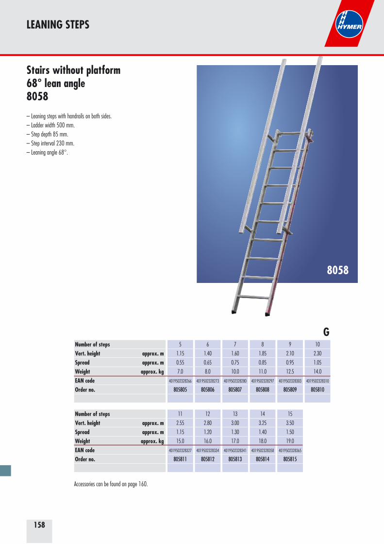
158
LEANING STEPS
8058
Stairs without platform 68° lean angle8058
– Leaning steps with handrails on both sides.– Ladder width 500 mm. – Step depth 85 mm. – Step interval 230 mm.– Leaning angle 68°.
Number of stepsVert. height approx. mSpread approx. mWeight approx. kgEAN codeOrder no.
5
1.15
0.55
7.0
4019502328266
805805
6
1.40
0.65
8.0
4019502328273
805806
7
1.60
0.75
10.0
4019502328280
805807
8
1.85
0.85
11.0
4019502328297
805808
9
2.10
0.95
12.5
4019502328303
805809
10
2.30
1.05
14.0
4019502328310
805810
11
2.55
1.15
15.0
4019502328327
805811
12
2.80
1.20
16.0
4019502328334
805812
13
3.00
1.30
17.0
4019502328341
805813
14
3.25
1.40
18.0
4019502328358
805814
15
3.50
1.50
19.0
4019502328365
805815
Number of stepsVert. height approx. mSpread approx. mWeight approx. kgEAN codeOrder no.
G
Accessories can be found on page 160.

159
LEANING STEPS
8060
Stairs with platform 68° lean angle 8060
– Leaning steps with handrails and guardrail.– Ladder width 500 mm. – Step depth 85 mm. – Step interval 230 mm.– Leaning angle 68°.
Number of stepsVert. height approx. mSpread approx. mWeight approx. kgEAN codeOrder no.
5
1.15
0.95
13.0
4019502328426
806005
6
1.40
1.00
14.0
4019502328433
806006
7
1.60
1.10
15.5
4019502328440
806007
8
1.85
1.20
16.5
4019502328457
806008
9
2.10
1.30
18.0
4019502328464
806009
10
2.30
1.40
19.0
4019502328471
806010
11
2.55
1.50
20.0
4019502328488
806011
12
2.80
1.60
21.0
4019502328495
806012
13
3.00
1.70
22.0
4019502328501
806013
14
3.25
1.80
23.0
4019502328518
806014
15
3.50
1.90
24.0
4019502328525
806015
Number of stepsVert. height approx. mSpread approx. mWeight approx. kgEAN codeOrder no.
G
Accessories can be found on page 160.
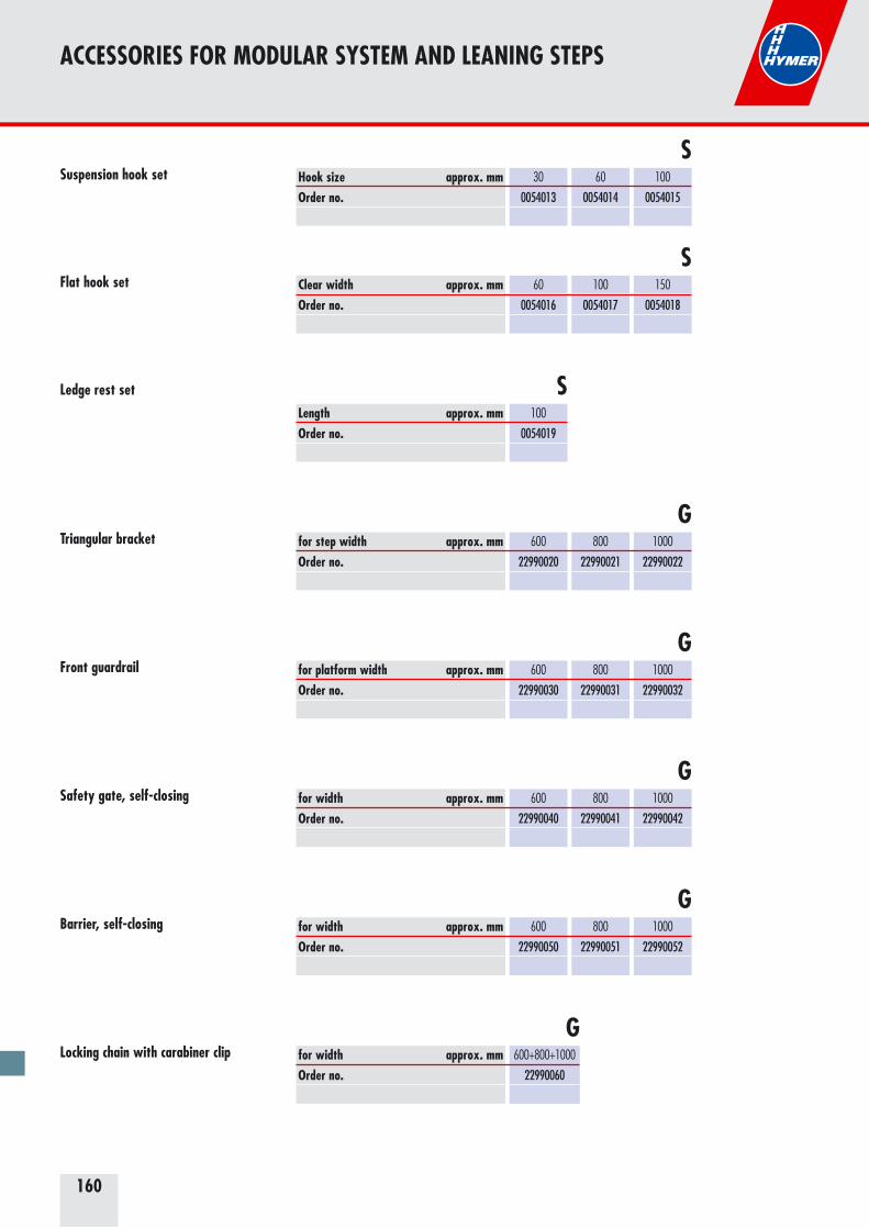
160
Hook size approx. mmOrder no.
30
0054013
60
0054014
100
0054015
Suspension hook set
Flat hook set
Ledge rest set
Triangular bracket
Front guardrail
Safety gate, self-closing
Barrier, self-closing
Locking chain with carabiner clip
Clear width approx. mmOrder no.
60
0054016
100
0054017
150
0054018
S
S
Length approx. mmOrder no.
100
0054019
S
for step width approx. mmOrder no.
600
22990020
800
22990021
1000
22990022
G
for platform width approx. mmOrder no.
600
22990030
800
22990031
1000
22990032
G
for width approx. mmOrder no.
600
22990040
800
22990041
1000
22990042
G
for width approx. mmOrder no.
600
22990050
800
22990051
1000
22990052
G
for width approx. mmOrder no.
600+800+1000
22990060
G
ACCESSORIES FOR MODULAR SYSTEM AND LEANING STEPS
161
Accessories 162
Spare parts 172
Quality features 178
Sales and delivery conditions 180
Index 182
Service
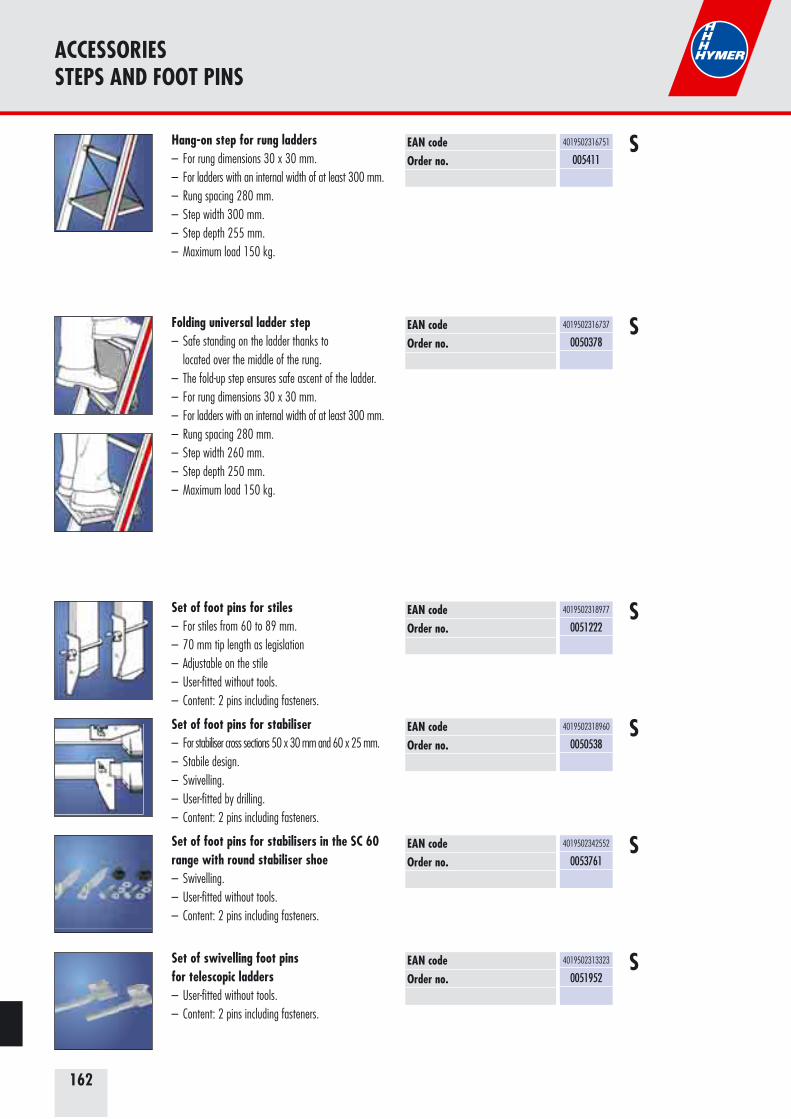
162
ACCESSORIESSTEPS AND FOOT PINS
EAN codeOrder no.
4019502316751
005411SHang-on step for rung ladders
– For rung dimensions 30 x 30 mm.– For ladders with an internal width of at least 300 mm.– Rung spacing 280 mm.– Step width 300 mm.– Step depth 255 mm.– Maximum load 150 kg.
EAN codeOrder no.
4019502316737
0050378
Folding universal ladder step– Safe standing on the ladder thanks to located over the middle of the rung.– The fold-up step ensures safe ascent of the ladder.– For rung dimensions 30 x 30 mm.– For ladders with an internal width of at least 300 mm.– Rung spacing 280 mm.– Step width 260 mm.– Step depth 250 mm.– Maximum load 150 kg.
S
EAN codeOrder no.
4019502318960
0050538
Set of foot pins for stabiliser – For stabiliser cross sections 50 x 30 mm and 60 x 25 mm.– Stabile design.– Swivelling.– User-fitted by drilling. – Content: 2 pins including fasteners.
EAN codeOrder no.
4019502318977
0051222
Set of foot pins for stiles– For stiles from 60 to 89 mm.– 70 mm tip length as legislation– Adjustable on the stile– User-fitted without tools.– Content: 2 pins including fasteners.
S
S
EAN codeOrder no.
4019502313323
0051952
Set of swivelling foot pins for telescopic ladders– User-fitted without tools.– Content: 2 pins including fasteners.
S
EAN codeOrder no.
4019502342552
0053761
Set of foot pins for stabilisers in the SC 60 range with round stabiliser shoe– Swivelling.– User-fitted without tools.– Content: 2 pins including fasteners.
S
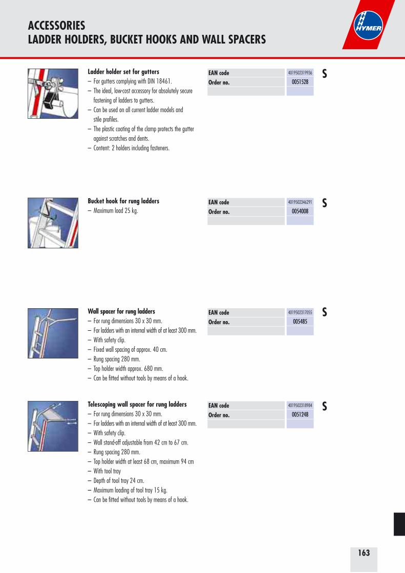
163
ACCESSORIES LADDER HOLDERS, BUCKET HOOKS AND WALL SPACERS
EAN codeOrder no.
4019502319936
0051528
Ladder holder set for gutters– For gutters complying with DIN 18461.– The ideal, low-cost accessory for absolutely secure fastening of ladders to gutters.– Can be used on all current ladder models and stile profiles.– The plastic coating of the clamp protects the gutter against scratches and dents. – Content: 2 holders including fasteners.
S
EAN codeOrder no.
4019502346291
0054008
Bucket hook for rung ladders – Maximum load 25 kg.
S
EAN codeOrder no.
4019502317055
005485
Wall spacer for rung ladders– For rung dimensions 30 x 30 mm.– For ladders with an internal width of at least 300 mm.– With safety clip.– Fixed wall spacing of approx. 40 cm.– Rung spacing 280 mm.– Top holder width approx. 680 mm.– Can be fitted without tools by means of a hook.
S
EAN codeOrder no.
4019502318984
0051248
Telescoping wall spacer for rung ladders– For rung dimensions 30 x 30 mm.– For ladders with an internal width of at least 300 mm.– With safety clip.– Wall stand-off adjustable from 42 cm to 67 cm.– Rung spacing 280 mm.– Top holder width at least 68 cm, maximum 94 cm– With tool tray– Depth of tool tray 24 cm.– Maximum loading of tool tray 15 kg.– Can be fitted without tools by means of a hook.
S
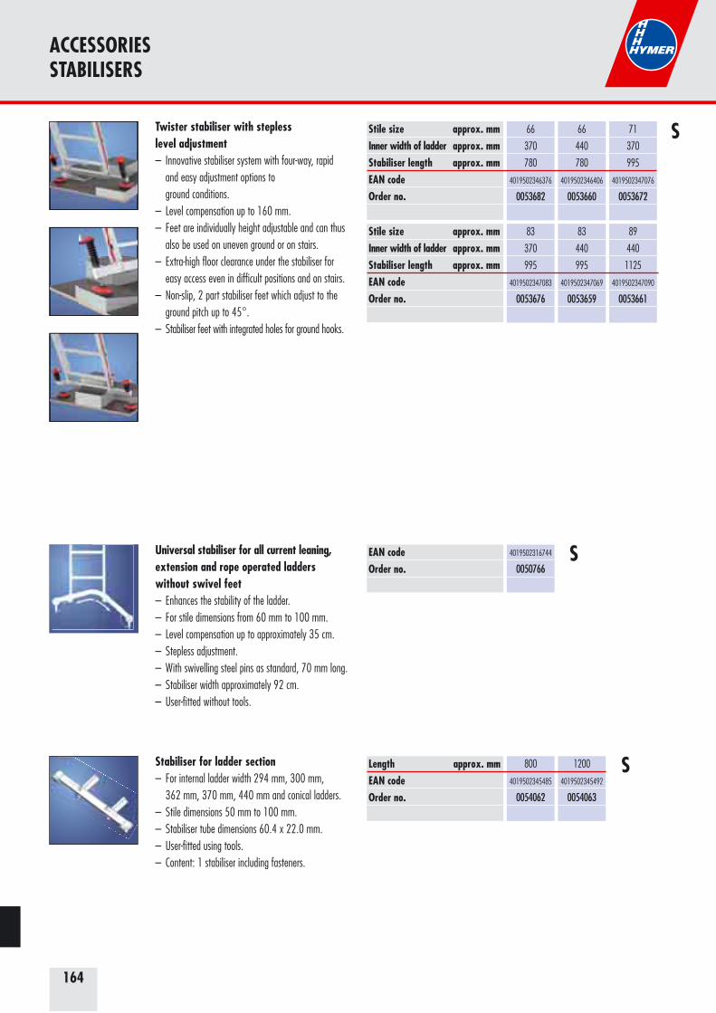
164
ACCESSORIESSTABILISERS
Twister stabiliser with stepless level adjustment– Innovative stabiliser system with four-way, rapid and easy adjustment options to ground conditions.– Level compensation up to 160 mm. – Feet are individually height adjustable and can thus also be used on uneven ground or on stairs.– Extra-high floor clearance under the stabiliser for easy access even in difficult positions and on stairs.– Non-slip, 2 part stabiliser feet which adjust to the ground pitch up to 45°. – Stabiliser feet with integrated holes for ground hooks.
EAN codeOrder no.
4019502316744
0050766
Universal stabiliser for all current leaning,extension and rope operated ladders without swivel feet– Enhances the stability of the ladder.– For stile dimensions from 60 mm to 100 mm.– Level compensation up to approximately 35 cm.– Stepless adjustment.– With swivelling steel pins as standard, 70 mm long.– Stabiliser width approximately 92 cm.– User-fitted without tools.
S
Stile size approx. mmInner width of ladder approx. mmStabiliser length approx. mmEAN codeOrder no.
Stile size approx. mmInner width of ladder approx. mmStabiliser length approx. mmEAN codeOrder no.
66
370
780
4019502346376
0053682
66
440
780
4019502346406
0053660
71
370
995
4019502347076
0053672
83
370
995
4019502347083
0053676
83
440
995
4019502347069
0053659
89
440
1125
4019502347090
0053661
S
Length approx. mmEAN codeOrder no.
800
4019502345485
0054062
1200
4019502345492
0054063
Stabiliser for ladder section– For internal ladder width 294 mm, 300 mm, 362 mm, 370 mm, 440 mm and conical ladders.– Stile dimensions 50 mm to 100 mm.– Stabiliser tube dimensions 60.4 x 22.0 mm.– User-fitted using tools.– Content: 1 stabiliser including fasteners.
S
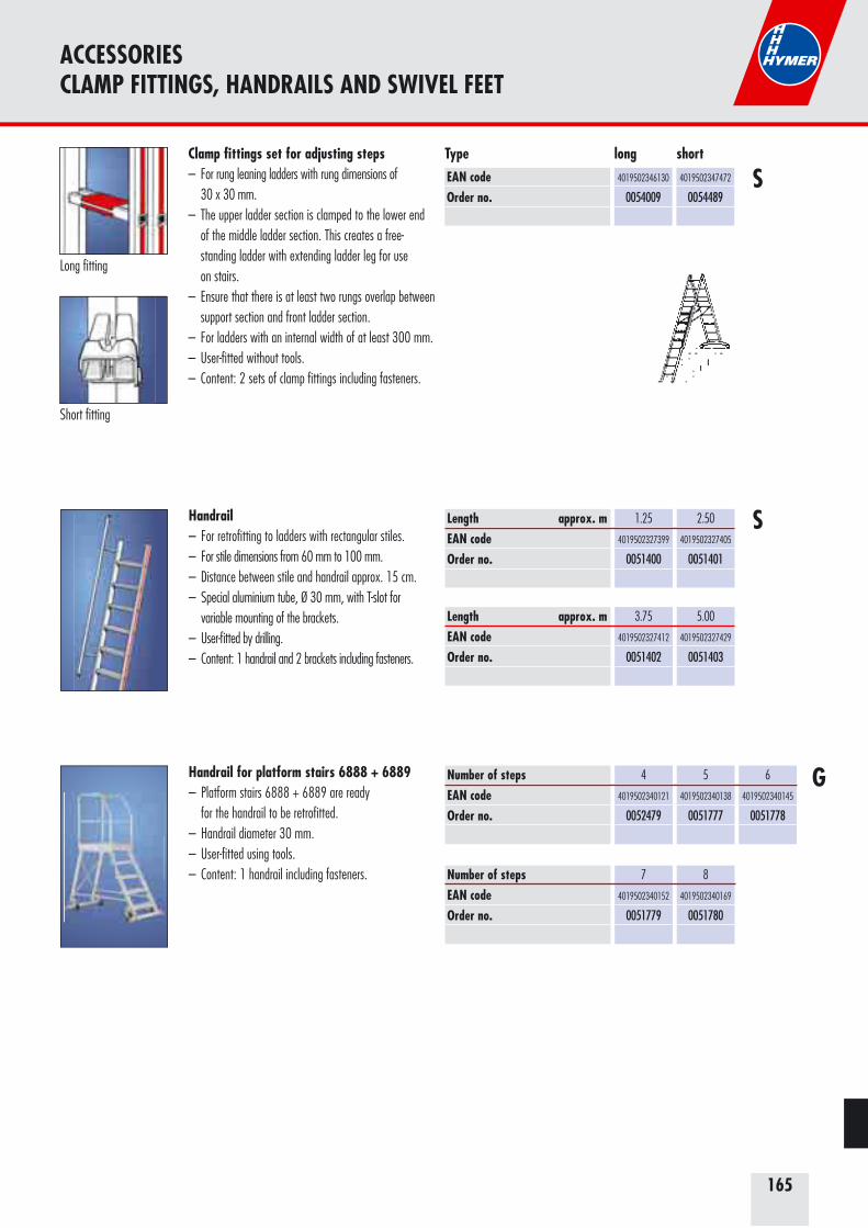
165
ACCESSORIESCLAMP FITTINGS, HANDRAILS AND SWIVEL FEET
EAN codeOrder no.
4019502346130
0054009
Clamp fittings set for adjusting steps– For rung leaning ladders with rung dimensions of 30 x 30 mm.– The upper ladder section is clamped to the lower end of the middle ladder section. This creates a free- standing ladder with extending ladder leg for use on stairs.– Ensure that there is at least two rungs overlap between support section and front ladder section.– For ladders with an internal width of at least 300 mm.– User-fitted without tools.– Content: 2 sets of clamp fittings including fasteners.
S
G
Length approx. mEAN codeOrder no.
Length approx. mEAN codeOrder no.
1.25
4019502327399
0051400
2.50
4019502327405
0051401
3.75
4019502327412
0051402
5.00
4019502327429
0051403
Handrail– For retrofitting to ladders with rectangular stiles.– For stile dimensions from 60 mm to 100 mm.– Distance between stile and handrail approx. 15 cm.– Special aluminium tube, Ø 30 mm, with T-slot for
variable mounting of the brackets.– User-fitted by drilling.– Content: 1 handrail and 2 brackets including fasteners.
Handrail for platform stairs 6888 + 6889– Platform stairs 6888 + 6889 are ready for the handrail to be retrofitted.– Handrail diameter 30 mm.– User-fitted using tools.– Content: 1 handrail including fasteners.
Number of steps EAN codeOrder no.
Number of steps EAN codeOrder no.
4
4019502340121
0052479
7
4019502340152
0051779
5
4019502340138
0051777
8
4019502340169
0051780
6
4019502340145
0051778
S
Long fitting
Short fitting
4019502347472
0054489
Type long short

166
ACCESSORIESFOOT EXTENSIONS
Universal foot extension set for free-standing rung ladders 4023+6023– Robust locking device.– Numerous possible uses on all stair types.– Continuously adjustable to 1,000 mm.– User-fitted without tools.– Content: 2 extensions including fasteners.
SStile size approx. mmAdjustment range approx. mm EAN codeOrder no.
60x24
1000
4019502316850
0050376
Foot extension for stabilisers– For all current rung leaning ladders with stabilisers.– For stile dimensions from 60 mm to 100 mm.– For stabiliser cross sections 50 x 30 mm and 60 x 25 mm.– Can be used with straight and curved stabilisers.– Adjustment range approximately 45 cm.– Stepless adjustment.– A spanner is required for first installation; then can be used without tools.– Content: 1 extension including fasteners.
Holmgröße ca. mmEAN-CodeBest.-Nr.
60 – 100
4019502326408
005650
S
Foot extension for timber rung standalone ladders, 7-1490 and 7-1410– Self-assembly without tools.– Content: 1 extension including fasteners.
EAN codeOrder no.
4019502347496
0079640
EAN codeOrder no.
4019502316874
0050302
Foot extension for telescopic ladders– Adjustment range approximately 45 cm.– Continuously adjustable from size 4 x 4.– Restrictions on use for size 4 x 3, i.e. cannot be pushed up. In this case, the foot extension must be removed.– User-fitted without tools.– Content: 1 extension including fasteners.
S
Stile size approx. mmEAN codeOrder no.
Stile size approx. mmEAN codeOrder no.
60
4019502316782
005550
66
4019502316799
005551
71
4019502316805
005552
100
4019502316829
005554
79/83
4019502316812
005553
89
4019502316843
0050149
Foot extension for rung ladders– For stile dimensions from 60 mm to 100 mm.– Adjustment range approximately 60 cm.– Stepless adjustment.– User-fitted without tools.– Content: 1 extension including fasteners.
S
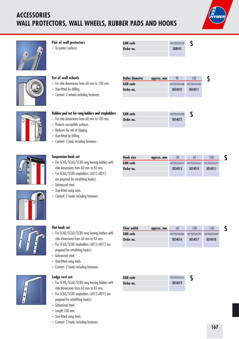
167
Suspension hook set– For SC40/SC60/SC80 rung leaning ladders with stile dimensions from 60 mm to 83 mm.– For SC60/SC80 stepladders (6012+8012
are prepared for retrofitting hooks).– Galvanized steel.– User-fitted using tools.– Content: 2 hooks including fasteners.
Hook size approx. mmEAN codeOrder no.
30
4019502345355
0054013
60
4019502345362
0054014
100
4019502345379
0054015
S
Flat hook set– For SC40/SC60/SC80 rung leaning ladders with stile dimensions from 60 mm to 83 mm.– For SC60/SC80 stepladders (6012+8012 are prepared for retrofitting hooks).– Galvanized steel.– User-fitted using tools.– Content: 2 hooks including fasteners.
Clear width approx. mmEAN codeOrder no.
60
4019502345386
0054016
100
4019502345393
0054017
150
4019502345409
0054018
S
Ledge rest set– For SC40/SC60/SC80 rung leaning ladders with stile dimensions from 60 mm to 83 mm.– For SC60/SC80 stepladders (6012+8012 are prepared for retrofitting hooks).– Galvanized steel.– Length 100 mm.– User-fitted using tools.– Content: 2 hooks including fasteners.
EAN codeOrder no.
4019502345416
0054019S
ACCESSORIESWALL PROTECTORS, WALL WHEELS, RUBBER PADS AND HOOKS
Roller diameter approx. mmEAN codeOrder no.
90
4019502345348
0054010
100
4019502346284
0054011
Set of wall wheels– For stile dimensions from 60 mm to 100 mm.– User-fitted by drilling.– Content: 2 wheels including fasteners.
S
Pair of wall protectors– To protect surfaces.
EAN codeOrder no.
4019502342378
008945S
EAN codeOrder no.
4019502345508
0054012
Rubber pad set for rung ladders and stepladders– For stile dimensions from 60 mm to 100 mm.– Protects susceptible surfaces.– Reduces the risk of slipping.– User-fitted by drilling.– Content: 2 pads including fasteners.
S

168
ACCESSORIESBAGS, SPRING CASTORS AND BRACES
Rigid brace set, detachable for 8024+8026– User-fitted by drilling and using tools.– Content: 2 braces including fasteners.
For typesNumber of stepsLength approx. mmEAN codeOrder no.
8024
2x2
259
4019502345843
0054020
8024
2x3
363
4019502345850
0054021
8024
2x4+2x5
550
4019502345867
0054022
8024
2x6+2x7
709
4019502345874
54023
For typesNumber of stepsLength approx. mmEAN codeOrder no.
8024
2x8+2x9+2x10
1009
4019502345881
0054024
8024
2x12
1329
4019502345898
0054025
For typesNumber of stepsLength approx. mmEAN codeOrder no.
8026
4+5
550
4019502345867
0054022
8026
6+7
709
4019502345874
0054023
8026
8+10
1009
4019502345881
0054024
8026
12+14
1329
4019502345898
0054025
S
EAN codeOrder no.
4019502345324
0054031SBag for wooden ladders
– Made from high-quality cotton.– Bag closed at the sides.– User-fitted using tools.– Content: 1 bag including fasteners.
EAN codeOrder no.
4019502345317
0054030SBag for aluminium ladders
– For rung dimensions 30 x 30 mm.– Made from high-quality cotton.– Bag closed at the sides.– User-fitted using hook-and-loop fastener.– Content: 1 bag.
Set of spring loaded castors, self-locking– On 8024+8026 only in conjunction with rigid braces.– Rigid braces on product as standard in the 8080– Castor diameter 50 mm.– User-fitted by drilling and using tools.– Content: 2 wheels including fasteners.
Spring-loaded castor type
EAN codeOrder no.
Spring-loaded castor type
EAN codeOrder no.
fixed
on the stile
4019502345805
0054026
swivelling
on the stile
4019502345812
0054027
fixed on
support section
4019502345829
0054028
swivelling on
support section
4019502345836
0054029
S
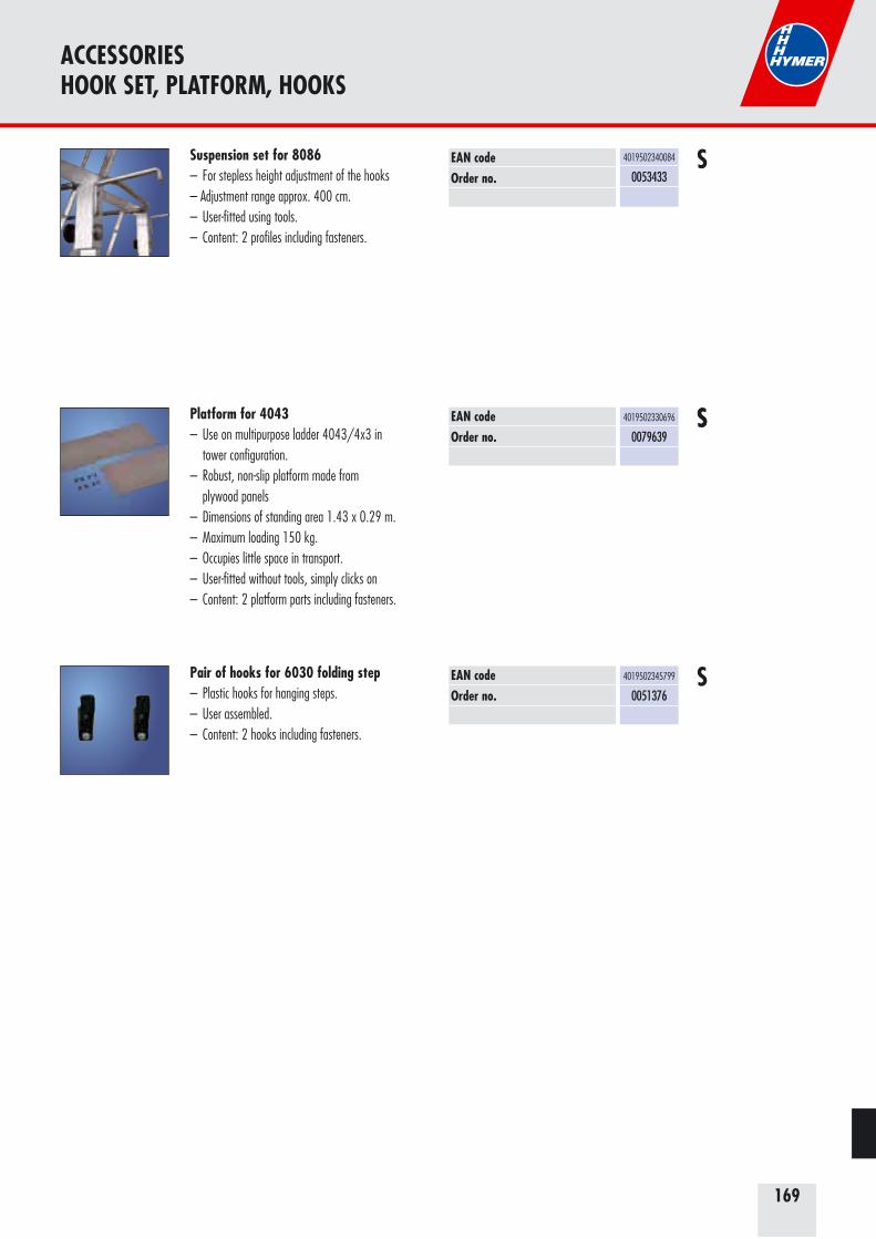
169
ACCESSORIESHOOK SET, PLATFORM, HOOKS
EAN codeOrder no.
4019502345799
0051376SPair of hooks for 6030 folding step
– Plastic hooks for hanging steps.– User assembled.– Content: 2 hooks including fasteners.
EAN codeOrder no.
4019502330696
0079639SSPlatform for 4043
– Use on multipurpose ladder 4043/4x3 in tower configuration.– Robust, non-slip platform made from plywood panels– Dimensions of standing area 1.43 x 0.29 m.– Maximum loading 150 kg.– Occupies little space in transport.– User-fitted without tools, simply clicks on– Content: 2 platform parts including fasteners.
Suspension set for 8086– For stepless height adjustment of the hooks– Adjustment range approx. 400 cm.– User-fitted using tools.– Content: 2 profiles including fasteners.
EAN codeOrder no.
4019502340084
0053433S
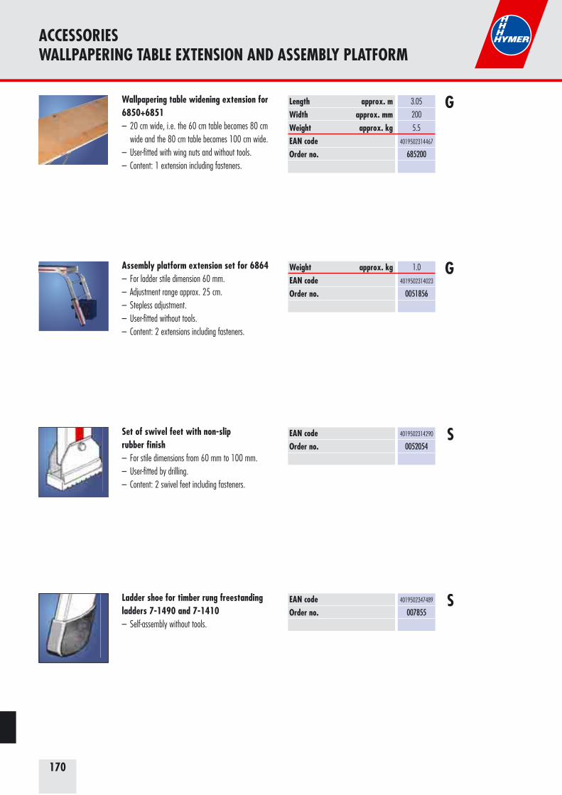
170
Assembly platform extension set for 6864– For ladder stile dimension 60 mm. – Adjustment range approx. 25 cm.– Stepless adjustment.– User-fitted without tools.– Content: 2 extensions including fasteners.
Weight approx. kgEAN codeOrder no.
1.0
4019502314023
0051856
G
Wallpapering table widening extension for 6850+6851– 20 cm wide, i.e. the 60 cm table becomes 80 cm wide and the 80 cm table becomes 100 cm wide.– User-fitted with wing nuts and without tools.– Content: 1 extension including fasteners.
Length approx. mWidth approx. mmWeight approx. kgEAN codeOrder no.
3.05
200
5.5
4019502314467
685200
G
ACCESSORIES WALLPAPERING TABLE EXTENSION AND ASSEMBLY PLATFORM
EAN codeOrder no.
EAN codeOrder no.
4019502314290
0052054
4019502347489
007855
Set of swivel feet with non-slip rubber finish– For stile dimensions from 60 mm to 100 mm.– User-fitted by drilling.– Content: 2 swivel feet including fasteners.
Ladder shoe for timber rung freestanding ladders 7-1490 and 7-1410– Self-assembly without tools.
S
S
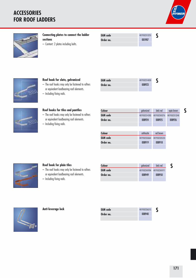
171
ACCESSORIES FOR ROOF LADDERS
Connecting plates to connect the ladder sections– Content: 2 plates including bolts.
Roof hook for slate, galvanized– The roof hooks may only be fastened to rafters or equivalent loadbearing roof elements.– Including fixing nails.
Roof hooks for tiles and pantiles– The roof hooks may only be fastened to rafters or equivalent loadbearing roof elements.– Including fixing nails.
Roof hook for plain tiles– The roof hooks may only be fastened to rafters or equivalent loadbearing roof elements.– Including fixing nails.
EAN codeOrder no.
EAN codeOrder no.
ColourEAN codeOrder no.
ColourEAN codeOrder no.
ColourEAN codeOrder no.
4019502313255
005907
4019502314030
008923
galvanized
4019502314283
008924
anthracite
4019502326064
008919
galvanized
4019502345904
008949
brick red
4019502343276
008925
red brown
4019502335233
008918
brick red
4019502345911
008950
sepia brown
4019502313248
008926
S
Anti-leverage lock EAN codeOrder no.
4019502336315
008940
S
S
S
S
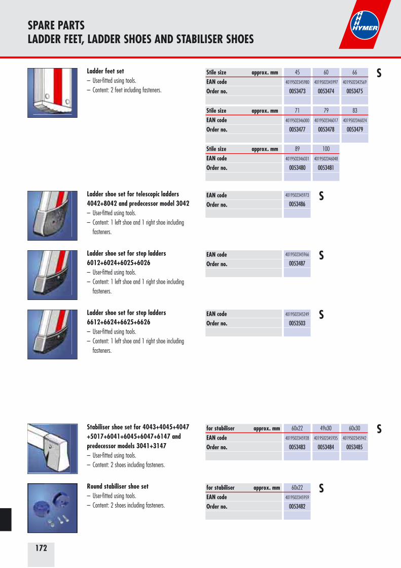
172
SPARE PARTSLADDER FEET, LADDER SHOES AND STABILISER SHOES
Stabiliser shoe set for 4043+4045+4047 +5017+6041+6045+6047+6147 and predecessor models 3041+3147 – User-fitted using tools.– Content: 2 shoes including fasteners.
for stabiliser approx. mmEAN codeOrder no.
60x22
4019502345928
0053483
49x30
4019502345935
0053484
60x30
4019502345942
0053485
S
Ladder shoe set for telescopic ladders 4042+8042 and predecessor model 3042– User-fitted using tools.– Content: 1 left shoe and 1 right shoe including fasteners.
EAN codeOrder no.
4019502345973
0053486S
Ladder shoe set for step ladders 6012+6024+6025+6026– User-fitted using tools.– Content: 1 left shoe and 1 right shoe including fasteners.
EAN codeOrder no.
4019502345966
0053487S
Ladder shoe set for step ladders 6612+6624+6625+6626– User-fitted using tools.– Content: 1 left shoe and 1 right shoe including fasteners.
EAN codeOrder no.
4019502345249
0053503S
Ladder feet set– User-fitted using tools.– Content: 2 feet including fasteners.
Stile size approx. mmEAN codeOrder no.
Stile size approx. mmEAN codeOrder no.
Stile size approx. mmEAN codeOrder no.
60
4019502345997
0053474
66
4019502342569
0053475
71
4019502346000
0053477
79
4019502346017
0053478
83
4019502346024
0053479
89
4019502346031
0053480
100
4019502346048
0053481
45
4019502345980
0053473
S
Round stabiliser shoe set– User-fitted using tools.– Content: 2 shoes including fasteners.
for stabiliser approx. mmEAN codeOrder no.
60x22
4019502345959
0053482
S
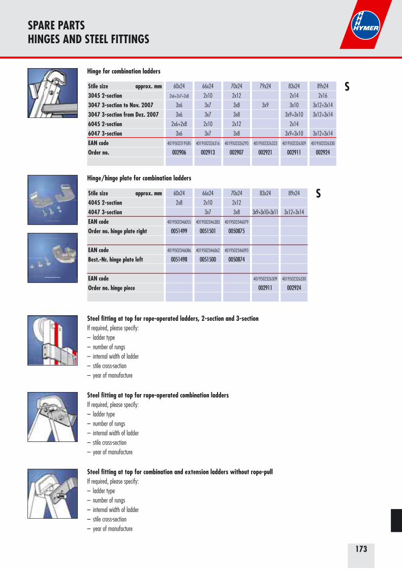
173
SPARE PARTSHINGES AND STEEL FITTINGS
Hinge for combination ladders
Stile size approx. mm3045 2-section3047 3-section to Nov. 20073047 3-section from Dez. 20076045 2-section6047 3-sectionEAN codeOrder no.
60x24
2x6+2x7+2x8
3x6
3x6
2x6+2x8
3x6
4019502319585
002906
66x24
2x10
3x7
3x7
2x10
3x7
4019502326316
002913
70x24
2x12
3x8
3x8
2x12
3x8
4019502326293
002907
79x24
3x9
4019502326323
002921
83x24
2x14
3x10
3x9+3x10
2x14
3x9+3x10
4019502326309
002911
89x24
2x16
3x12+3x14
3x12+3x14
3x12+3x14
4019502326330
002924
S
Hinge/hinge plate for combination ladders
Stile size approx. mm4045 2-section4047 3-sectionEAN codeOrder no. hinge plate right
EAN codeBest.-Nr. hinge plate left
EAN codeOrder no. hinge piece
60x24
2x8
4019502346055
0051499
4019502346086
0051498
66x24
2x10
3x7
4019502346383
0051501
4019502346062
0051500
70x24
2x12
3x8
4019502346079
0050875
4019502346093
0050874
83x24
3x9+3x10+3x11
4019502326309
002911
89x24
3x12+3x14
4019502326330
002924
S
Steel fitting at top for rope-operated ladders, 2-section and 3-sectionIf required, please specify:– ladder type– number of rungs– internal width of ladder– stile cross-section– year of manufacture
Steel fitting at top for rope-operated combination laddersIf required, please specify:– ladder type– number of rungs– internal width of ladder– stile cross-section– year of manufacture
Steel fitting at top for combination and extension ladders without rope-pullIf required, please specify:– ladder type– number of rungs– internal width of ladder– stile cross-section– year of manufacture
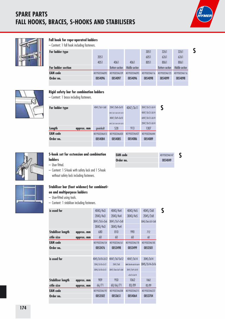
174
SPARE PARTSFALL HOOKS, BRACES, S-HOOKS AND STABILISERS
Fall hook for rope-operated ladders– Content: 1 fall hook including fasteners.
For ladder type
For ladder sectionEAN codeOrder no.
2051
4051
4019502346093
0054096
4061
Bottom section
4019502346109
0054097
4061
Middle section
4019502346093
0054096
3051
6051
8051
4019502346116
0054098
3261
6261
8061
Bottom section
4019502346123
0054099
3261
6261
8061
Middle section
4019502346116
0054098
S-hook set for extension and combination ladders – User fitted.– Content: 1 S-hook with safety lock and 1 S-hook without safety lock including fasteners.
EAN codeOrder no.
4019502346147
0054049
Stabiliser bar (foot widener) for combinati-on and multipurpose ladders– User-fitted using tools.– Content: 1 stabiliser including fasteners.
S
S
Rigid safety bar for combination ladders– Content: 1 brace including fasteners.
For ladder type
Length approx. mmEAN codeOrder no.
4047/3x7+3x8
gewinkelt
4019502346413
0054084
2047/3x8+3x10
3047/3x7+3x8+3x9+3x10
4047/3x9+3x10
6047/3x7+3x8+3x9+3x10
528
4019502346420
0054085
4047/3x11
913
4019502346437
0054086
3047/3x12+3x14
4047/3x12+3x14
6047/3x12+3x14
2047/3x12+3x14
1307
4019502346444
0054089
S
is used for
Stabiliser length approx. mmstile size approx. mmEAN codeOrder no.
4043/4x3
2043/4x3
3041/2x5+2x6
3043/4x3
680
60
4019502346154
0053476
4043/4x4
2043/4x4
3041/2x7+2x8
3043/4x4
810
60
4019502346161
0053498
4043/4x5
3043/4x5
990
60
4019502346178
0053499
4045/2x8
2045/2x8
3045/2x6+2x7+2x8
712
60
4019502346185
0053501
is used for
Stabiliser length approx. mmstile size approx. mmEAN codeOrder no.
4045/2x10+2x12
2045/2x10+2x12
3045/2x10+2x12
909
66/71
4019502346192
0053502
4047/3x7-3x12
2047/3x8
3047/3x6+3x7+3x8
950
60/66/71
4019502346208
0053651
4047/3x14
2047/3x10+3x12+3x14
3047/3x9+3x10
+3x12+3x14
1062
83/89
4019502346215
0054064
2045/2x14
3045/2x14+2x16
1062
83/89
4019502346222
0053704
S

175
SPARE PARTSSPREADER BRACE FUNCTION, NYLON ROPE, ROPE PULLEY BRACKET, HINGES, RUNG COVERS AND SPARE PARTS FOR TELESTEG
Rope pulley bracket set for rope operated ladders 4051+4061+6051+6147+6261+8051+8061– For rungs 30 x 30 mm.– Rope pulley, 70 mm diameter.
Pair of hinges for rung leaning ladders 4023+6023– Content: 2 hinge pairs including fasteners.
Stile size approx. mmEAN codeOrder no.
60
4019502345287
0054045
71
4019502345294
0054046
Rung cover set for telescopic ladders 4042+6042+8042+8044– Content: 2 covers for rungs with locking device and 10 covers for rungs without locking device.
EAN codeOrder no.
4019502343016
0054047
Cotter pin set for Telesteg 6859– Content: 2 cotter pins.
EAN codeOrder no.
4019502346239
0053500
Hook locking set for Telesteg 6859– Content: 1 latch hook and 1 spring.
EAN codeOrder no.
4019502346246
0053758
Telescoping locking set for Telesteg 6859– Content: 1 catch and 1 spring.
EAN codeOrder no.
4019502345270
0054044
Safety strapIf required, please specify:– Ladder type.– Number of rungs.– Stile cross-section.– Year of manufacture.
Nylon rope If required, please specify:– Ladder type.– Number of rungs.– Internal width of ladder.– Stile cross-section.– Year of manufacture.
EAN codeOrder no.
4019502345300
0054048S
S
S
G
G
G
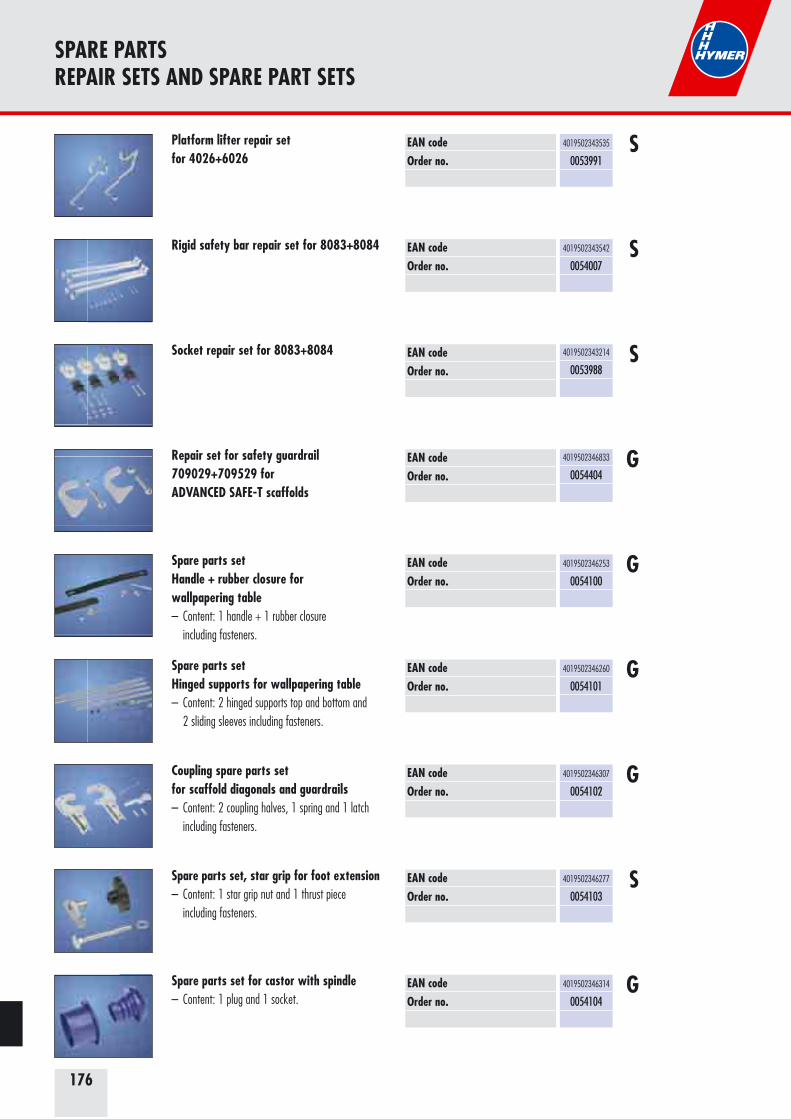
176
SPARE PARTSREPAIR SETS AND SPARE PART SETS
EAN codeOrder no.
4019502343535
0053991SPlatform lifter repair set
for 4026+6026
EAN codeOrder no.
4019502343542
0054007SRigid safety bar repair set for 8083+8084
SEAN codeOrder no.
4019502343214
0053988
Socket repair set for 8083+8084
EAN codeOrder no.
4019502346253
0054100GSpare parts set
Handle + rubber closure for wallpapering table– Content: 1 handle + 1 rubber closure including fasteners.
EAN codeOrder no.
4019502346260
0054101GSpare parts set
Hinged supports for wallpapering table– Content: 2 hinged supports top and bottom and 2 sliding sleeves including fasteners.
EAN codeOrder no.
4019502346307
0054102GCoupling spare parts set
for scaffold diagonals and guardrails– Content: 2 coupling halves, 1 spring and 1 latch including fasteners.
EAN codeOrder no.
4019502346277
0054103SSpare parts set, star grip for foot extension
– Content: 1 star grip nut and 1 thrust piece including fasteners.
EAN codeOrder no.
4019502346314
0054104GSpare parts set for castor with spindle
– Content: 1 plug and 1 socket.
GEAN codeOrder no.
4019502346833
0054404
Repair set for safety guardrail709029+709529 forADVANCED SAFE-T scaffolds
177
FOR YOUR NOTES
178
HYMER „MADE IN GERMANY“ QUALITY
Custom quality products
If you insist on Hymer, you insist on qualityHymer Leichtmetallbau also demonstrates compliance with the relevant standards and inspection regulations by internal inspections in accordance with the standards. We have established our own inspection laboratory to do this. Independent test institutes have certified our results. Our test certificate was issued on the basis of the German Equipment and Product Safety Law (GPSG).
Quality management systemHymer Leichtmetallbau is certified to EN ISO 9001:2008.The determination and implementation of customer requirements, product develop-ment, service and the qualification of our staff are the focus of this certification. We are continuously at work on developing ourselves in all areas beyond the quality management system.Our current certificates may be downloaded from our website www.hymer.de.
EN 131 – the standard for EuropeHymer Leichtmetallbau guarantees compliance with the standard throughout the range of ladders. All current Hymer ladders and mobile towers have been tested and carry the German GS “Safety Tested” mark.
The test methodsAll current ladders and mobile towers have been subjected to inspection voluntarily. The test methods applied by all institutions are based on EN 131 for ladders and EN 1004 for mobile towers. A certificate for all products tested by a test institute can be requested. It is not only our products, but also our manufacturing processes that are regularly audited by independent test institutes during the course of these GS inspections.
179
German quality productsHymer Leichtmetallbau is a member of the VDL – the German Association of Manu-facturers of Ladders and Mobile Towers. This, too, is a mark of quality.
Hymer Leichtmetallbau insists on safetyOne of the tests Hymer products are subjected to is the endurance test. The high qual-ity standard is demonstrated with an extraordinary guarantee for each product series.
Satisfied customers are our goal Hymer Leichtmetallbau stands by the quality of its products by offering long warran-ties. The aluminium ladders with the red stripe down the side guarantee simple and safe use. The quality of the seamlessly extrude profiles satisfies even the highest demands. Hymer products have won friends with their outstanding design. A perfect form with many innovative details.
HYMER „MADE IN GERMANY“ QUALITY
180
TERMS OF SALE AND DELIVERY
Terms of Sale and DeliveryAs at 15.11.2007
Terms of Sale and Delivery Our Terms of Sale and Delivery form part of all offers and contracts. Customer's purchasing conditions are only binding on us if they have been expressly confirmed by us in writing.
I. Offer and conclusion of contract 1. The order is only deemed to be accepted if it has been confirmed by us in writing. Until such time, our offer is subject to alteration. 2. Alterations or additions on the part of the customer compared to the original order and all supplemen-tary agreements reached by the parties to the contract with regard to the order also require our written confirmation in order to be valid. 3. To observe the written form, it is sufficient to make the additions, alterations or supplementary agreements reached available to the customer in the text in quoted but unsigned form. II. Delivery Goods are shipped at the expense and risk of the customer. The customer also bears the risk when carriage paid delivery is agreed. The customer is to arrange for insurance of the goods during transport at his expense. In the case of free delivery, the freight payment is to be regarded as an expense incurred on behalf of the customer. III. PackagingPackaging is invoiced at cost. Boxes returned carriage paid in perfect condition are credited at two thirds of the invoiced value unless otherwise agreed in writing.IV. Delivery time1. The agreed delivery time becomes binding as soon as all details of execution have been clarified and both parties agree on all conditions of the transaction. Their observance assumes the fulfilment of the contractual obligations of the customer.2. If the delivery period is exceeded, the customer shall to grant a reasonable grace period. Failure to complete delivery within the grace period constitutes a delay in delivery. Our liability for a delay in delivery in the case of simple negligence is limited to the net invoice value (excluding VAT, freight and packaging costs) of the delayed delivery/part shipment. 3. The delivery period is extended to a reasonable extent if we are prevented from effecting delivery on schedule due to unforeseeable circumstances which cannot be averted despite due care in the individual case and which demonstrably have a considerable effect on completion or delivery of the product or ser-vice. This also applies if the reason for prevention occurs under the same conditions with a subcontractor. Such grounds are, in particular, production outages, delays in the delivery of components and raw materi-als, strikes and lockouts. In such cases we are only liable to the customer for intent and gross negligence as described in paragraph 2, sentence 2. 4. If the delivery/performance becomes impossible, we will immediately inform the customer of this and reimburse payments already effected. We are then entitled to withdraw partially or fully from the contract. Our liability is limited in accordance with paragraph 3, sentence 4 in connection with paragraph 2, sentence 2. If we are not supplied by subcontractors to such an extent that we can meet our delivery obligations on schedule and/or in full, we are entitled to adapt our delivery/performance obligation and carry out part shipments if and in so far as the customer can be reasonably expected to accept them. V. Liability for defects We are liable for defects as follows: 1. Those parts or services which become unusable or the usefulness of which is considerably impaired wi-thin 12 months, calculated from the day of the passage of risk as a result of a circumstance which existed before the passage of risk, in particular due to faulty construction, defective material or poor workmanship are to be repaired or replaced at our discretion. The customer must report the detection of such defects in writing immediately after receipt of the goods at their destination. Claims under the warranty require that the customer correctly fulfil his due obligation of inspection and complaint in accordance with sections 377, 378 HGB (German Commercial Code). 2. The customer shall fulfil his contractual obligations, in particular the agreed payment conditions. Complaints do not entitle the customer not to fulfil his own contractual obligations, to offset charges or assert a right of retention unless the legitimacy of the complaint is recognised or finally decided with legal effect and without reservation.3. The customer shall grant us the necessary time and opportunity to eliminate defects using equitable discretion. If the customer definitively refuses a possible repair which he can reasonably be expected to accept, we are exempted from all liability for defects. If a reasonable period of additional time granted by the customer to eliminate defects is not observed by us or if the repair fails or is impossible, the customer
is entitled to the statutory warranty rights. 4. No warranty is given for damage which is due to natural wear, incorrect treatment, insufficient mainte-nance, excessive strain or use of unsuitable operating materials. 5. a) Incorrect alterations and repair work carried out on our goods/services by the customer or third parties exempt us from liability for consequences of this. b) Costs incurred by the customer as a result of the elimination of defects subject to guarantee by third parties are only reimbursed if elimination by the third party has been previously approved by us or could not be postponed for reasons of operational safety or to prevent further damage. c) Further claims of the customer against us and our vicarious agents are excluded if the repair has led to an elimination of the defect. d) If the customer asserts claims for compensation which do not constitute bodily injury and/or damage to health or loss of life, we are only liable for cases of intent and gross negligence. If we cannot be held re-sponsible for intentional violation of the contract, liability is limited to the foreseeable damage which may typically occur. This regulation also applies if we culpably violate typical, important contractual obligations.6. In the event of resale, the customer is obliged to agree guarantee conditions with his customer with the same content in so far as permissible by law. If he fails to do so, the customer has to exempt us accordingly in the event of assertion of claims by a third party. 7. Warranty declarations are not issued to the customer. Warranty liability to the end consumer remains unaffected. 8. If the customer receives erroneous assembly instructions, we are only obliged to supply correct assembly instructions and only if the error in the assembly instructions prevents correct assembly. VI. Further liability 1. Liability for compensation beyond that described in section V. is excluded, irrespective of the legal nature of the asserted claim. This comprises claims based on contract and tort. The limitation of liability does not apply to physical injury and damage to health or loss of life attributable to us. 2. Claims for compensation due to impossibility remain unaffected. The same applies if the liability is impe-rative based on the provisions of the product liability act. If compensation liability is restricted or excluded for us, this also applies to the legally permissible extent with regard to the liability of our employees and vicarious agents. VII. Exclusion of onward delivery to the USA, exemption from liabilityThe customer is not entitled to forward our goods directly or indirectly to the USA, US territories and Cana-da. If claims are asserted against us due to such a delivery to the USA, US territories and Canada based on warranty and/or product liability, the customer exempts us from all resulting claims. VIII. Reservation of title We reserve the right to ownership of the delivered goods until full payment of our claims from the business relationship, including any refinance bills or reverse bills of exchange. The customer is entitled to dispose of the delivered goods in the ordinary course of business. In addition, it is agreed: 1. Our ownership extends to the new products created by further processing of the conditional commodity. In the case of processing, connection or mixing with items which do not belong to us, we acquire co-ownership in accordance with sections 947, 948 BGB. No claims against us arise for the customer from processing the conditional commodity for us and from its storage. 2. From now on the customer assigns all claims from the sale of conditional commodities from our current or future deliveries of goods including bills of exchange and cheques to us to safeguard the relevant claims in accordance with paragraph 1. In the case of the resale of goods of which we have co-ownership in ac-cordance with paragraph 2, sentence 2, the assignment is restricted to the proportion of the claims which corresponds to our share of co-ownership. If a conditional commodity is sold together with other items for a total price, the assignment is restricted to the proportional amount of our invoice (including VAT) for the conditional commodity included in the sale. In the case of processing in the context of a contract for work performed, the claims for the proportional amount of our calculation (including VAT) for the conditional commodity also processed are already assigned to us now. 3. As long as the customer is prepared and able to correctly fulfil his obligations to us, he may dispose of the goods which we own in the ordinary course of business and collect the claims assigned to us himself. He may only carry out assignments as securities, pledges and assignments of claims, also in the way of a sale of claims, with our prior written commission; this also applies to export business. If we consider that the realisation of our claims is endangered, the buyer has to inform us at our request of the stocks of the conditional commodity and enable us to take them back, in addition, he has to inform his customers of the assignment and supply us with all necessary information and documents. When conditional commodities are taken back, a withdrawal from the contract only exists if this is expressly declared in writing. 4. If the value of the securities existing for us exceeds the claims to be secured by more than 20 %, we will also release appropriate securities ourselves or arrange for their release at our discretion at the request of the customer.
181
Guarantee conditionsThe quality management system introduced by Hymer Leichtmetallbau GmbH & Co. KG meets the requirements of ISO 9001:2008. All Hymer products are made of best quality materials and must meet the highest standards of quality. We can therefore offer a guarantee as follows:
1. Guarantee period Hymer SC 80 ladder range = 15 years Hymer SC 60 ladder range = 10 years Hymer SC 40 ladder range = 5 years
For all other product groups of the ladder and tower ranges, a guarantee period of 5 years applies, with a warranty period of 2 years for customer-specific solutions. We refer here to our guarantee details on the relevant product pages in this catalogue.
For all other ranges (e.g. commodities, ALU-PRO and Alpe), as well as products of the automotive enginee-ring sector, the statutory warranty rights apply.
2. Terms of guaranteea. The guarantee begins on the day of purchase. Invoices or receipts serve as proof of purchase. b. The guarantee is exclusively restricted to material defects of aluminium and steel parts.c. The guarantee does not cover the hinges on any ladders.d. The guarantee does not cover damage due to natural wear, incorrect treatment or modifications of the product. e. In the event of a warranty claim, we will repair or replace at our discretion. f. These guarantee conditions apply to all Hymer products listed under point 1 purchased after 01 April 2008.
3. ReturnThe guarantee holder shall return the product for inspection or general determination of the warranty case at his expense and risk to the place of fulfilment (Hymer-Leichtmetallbau, Wangen, Germany). If the guarantee claim is accepted, Hymer-Leichtmetallbau will reimburse the cost of the cheapest means of transport.
S = standard rangeG = equipment range
Written information on the products and images thereof may differ from the actual design in individual cases. Errors, and the right to make design modifications and vary prices in the case of changes in raw material prices remain reserved.
IX. Payment conditions 1. The invoice amounts are payable within 10 days with 2 % cash discount or after 30 days net unless otherwise agreed. 2. If different payment conditions become necessary for time reasons to those stated in our offers and order confirmations, these come into effect without the need for prior notice. 3. The retention of amounts owed to us due to any additional claims and offsetting with counter-claims are not permitted unless these claims are undisputed or decided with legal effect.4. If after conclusion of the contract there are doubts concerning the creditworthiness of the customer, we can make the continuation of the deliveries dependent on the immediate payment of the purchase price and outstanding claims. We can also demand immediate payment for invoice amounts not yet due and, if we have not yet delivered, payment before delivery. 5. If we accept bills of exchange, discount and bank charges are borne by the buyer.6. We accept no responsibility for punctual presentation and protests. Bill of exchange payments do not constitute cash payments. X. Obligations in the event of resale1. If advance payment has not yet been effected, our customer is obliged in accordance with the assignment agreed in paragraph IX. no. 6 to regard payments received for the goods resold by him as received for us and to pay them to us. He is also obliged at our request to send us a written declaration of assignment of his claim against his customer in the amount of the debt and a letter of notification to the customer involved without delay. We also assert the right to the goods commissioned by our customers with third parties.2. The customer has to include all product information, in particular operating instructions and assembly instructions, on delivery of the product purchased by the customer and submit them to the end customer. The customer is to obtain confirmation of receipt from the end customer. XI. Place of fulfilment place of jurisdiction, arbitration proceedings The place of fulfilment is Wangen. The place of jurisdiction for all disputes resulting from this contractual relationship is the District Court of Ravensburg. However, as the plaintiff we are also entitled at our discretion to bring an action at the court responsible for the registered seat of the defendant. The parties to the contract have the right to appeal to the court of arbitration of the Chamber of Industry and Commerce of Lake Constance-Upper Swabia (Germany) without recourse to the ordinary courts of law in accordance with the of the relevant valid rules of arbitration. XII. Binding nature of the contract In the event of legal ineffectiveness or changes of individual points of the provisions, the remainder of the contract remains binding. The parties to the contract will immediately replace an ineffective regulation with a new regulation which most closely reflects the economic purpose of the ineffective regulation. The contract is exclusively based on the valid law of the Federal Republic of Germany. XIII. The customer agrees to storage by us of company and personal data in the course of business transactions. (The currently valid Terms of Sale and Delivery can be viewed on our website and printed out at any time)
TERMS OF SALE AND DELIVERY
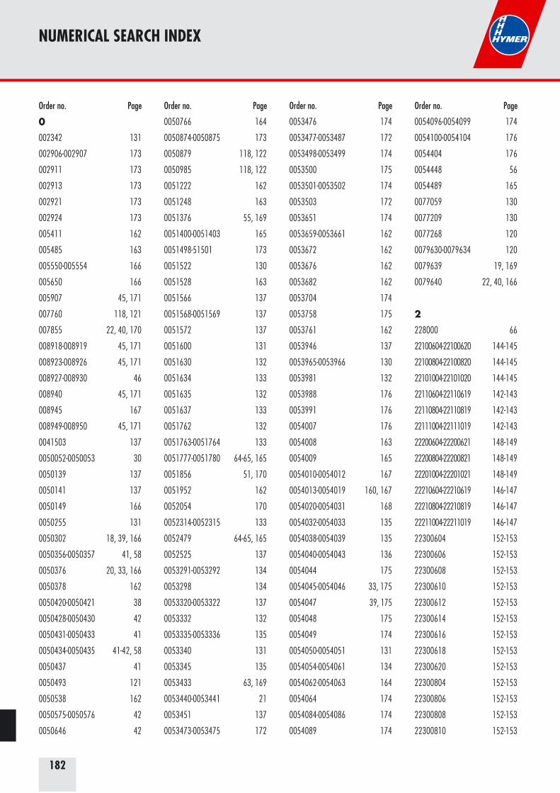
182
NUMERICAL SEARCH INDEX
0
002342 131
002906-002907 173
002911 173
002913 173
002921 173
002924 173
005411 162
005485 163
005550-005554 166
005650 166
005907 45, 171
007760 118, 121
007855 22, 40, 170
008918-008919 45, 171
008923-008926 45, 171
008927-008930 46
008940 45, 171
008945 167
008949-008950 45, 171
0041503 137
0050052-0050053 30
0050139 137
0050141 137
0050149 166
0050255 131
0050302 18, 39, 166
0050356-0050357 41, 58
0050376 20, 33, 166
0050378 162
0050420-0050421 38
0050428-0050430 42
0050431-0050433 41
0050434-0050435 41-42, 58
0050437 41
0050493 121
0050538 162
0050575-0050576 42
0050646 42
0050766 164
0050874-0050875 173
0050879 118, 122
0050985 118, 122
0051222 162
0051248 163
0051376 55, 169
0051400-0051403 165
0051498-51501 173
0051522 130
0051528 163
0051566 137
0051568-0051569 137
0051572 137
0051600 131
0051630 132
0051634 133
0051635 132
0051637 133
0051762 132
0051763-0051764 133
0051777-0051780 64-65, 165
0051856 51, 170
0051952 162
0052054 170
0052314-0052315 133
0052479 64-65, 165
0052525 137
0053291-0053292 134
0053298 134
0053320-0053322 137
0053332 132
0053335-0053336 135
0053340 131
0053345 135
0053433 63, 169
0053440-0053441 21
0053451 137
0053473-0053475 172
0053476 174
0053477-0053487 172
0053498-0053499 174
0053500 175
0053501-0053502 174
0053503 172
0053651 174
0053659-0053661 162
0053672 162
0053676 162
0053682 162
0053704 174
0053758 175
0053761 162
0053946 137
0053965-0053966 130
0053981 132
0053988 176
0053991 176
0054007 176
0054008 163
0054009 165
0054010-0054012 167
0054013-0054019 160, 167
0054020-0054031 168
0054032-0054033 135
0054038-0054039 135
0054040-0054043 136
0054044 175
0054045-0054046 33, 175
0054047 39, 175
0054048 175
0054049 174
0054050-0054051 131
0054054-0054061 134
0054062-0054063 164
0054064 174
0054084-0054086 174
0054089 174
0054096-0054099 174
0054100-0054104 176
0054404 176
0054448 56
0054489 165
0077059 130
0077209 130
0077268 120
0079630-0079634 120
0079639 19, 169
0079640 22, 40, 166
2
228000 66
22100604-22100620 144-145
22100804-22100820 144-145
22101004-22101020 144-145
22110604-22110619 142-143
22110804-22110819 142-143
22111004-22111019 142-143
22200604-22200621 148-149
22200804-22200821 148-149
22201004-22201021 148-149
22210604-22210619 146-147
22210804-22210819 146-147
22211004-22211019 146-147
22300604 152-153
22300606 152-153
22300608 152-153
22300610 152-153
22300612 152-153
22300614 152-153
22300616 152-153
22300618 152-153
22300620 152-153
22300804 152-153
22300806 152-153
22300808 152-153
22300810 152-153
Order no. Page Order no. Page Order no. Page Order no. Page
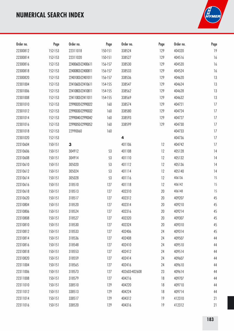
183
NUMERICAL SEARCH INDEX
22300812 152-153
22300814 152-153
22300816 152-153
22300818 152-153
22300820 152-153
22301004 152-153
22301006 152-153
22301008 152-153
22301010 152-153
22301012 152-153
22301014 152-153
22301016 152-153
22301018 152-153
22301020 152-153
22310604 150-151
22310606 150-151
22310608 150-151
22310610 150-151
22310612 150-151
22310614 150-151
22310616 150-151
22310618 150-151
22310620 150-151
22310804 150-151
22310806 150-151
22310808 150-151
22310810 150-151
22310812 150-151
22310814 150-151
22310816 150-151
22310818 150-151
22310820 150-151
22311004 150-151
22311006 150-151
22311008 150-151
22311010 150-151
22311012 150-151
22311014 150-151
22311016 150-151
22311018 150-151
22311020 150-151
22400603-22400611 156-157
22400803-22400811 156-157
22401003-22401011 156-157
22410603-22410611 154-155
22410803-22410811 154-155
22411003-22411011 154-155
22990020-22990022 160
22990030-22990032 160
22990040-22990042 160
22990050-22990052 160
22990060 160
3
304912 53
304914 53
305020 53
305024 53
305028 53
318510 127
318513 127
318517 127
318520 127
318524 127
318527 127
318530 127
318533 127
318536 127
318548 127
318553 127
318559 127
318565 127
318573 127
318579 127
338510 129
338513 129
338517 129
338520 129
338524 129
338527 129
338530 129
338533 129
338536 129
338547 129
338562 129
338569 129
338574 129
338580 129
338593 129
338599 129
4
401106 12
401108 12
401110 12
401112 12
401114 12
401116 12
401118 12
402310 20
402312 20
402314 20
402316 20
402320 20
402324 20
402406 24
402408 24
402410 24
402412 24
402414 24
402416 24
402603-402608 23
404216 18
404220 18
404224 18
404312 19
404316 19
404320 19
404516 16
404520 16
404524 16
404620 13
404624 13
404628 13
404632 13
404721 17
404724 17
404727 17
404730 17
404733 17
404736 17
404742 17
405128 14
405132 14
405136 14
405140 14
406136 15
406142 15
406148 15
409207 45
409210 45
409214 45
409307 45
409310 45
409314 45
409507 44
409510 44
409514 44
409607 44
409610 44
409614 44
409707 44
409710 44
409714 44
412310 21
412312 21
Order no. Page Order no. Page Order no. Page Order no. Page
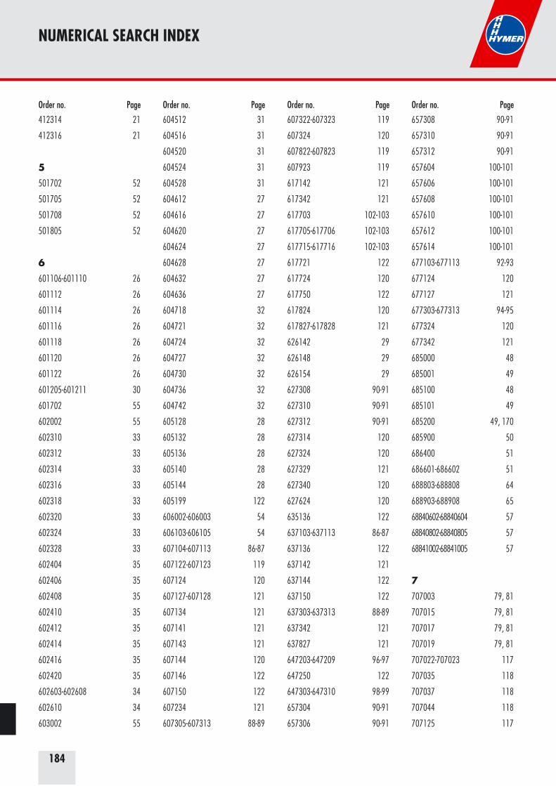
184
NUMERICAL SEARCH INDEX
412314 21
412316 21
5
501702 52
501705 52
501708 52
501805 52
6
601106-601110 26
601112 26
601114 26
601116 26
601118 26
601120 26
601122 26
601205-601211 30
601702 55
602002 55
602310 33
602312 33
602314 33
602316 33
602318 33
602320 33
602324 33
602328 33
602404 35
602406 35
602408 35
602410 35
602412 35
602414 35
602416 35
602420 35
602603-602608 34
602610 34
603002 55
604512 31
604516 31
604520 31
604524 31
604528 31
604612 27
604616 27
604620 27
604624 27
604628 27
604632 27
604636 27
604718 32
604721 32
604724 32
604727 32
604730 32
604736 32
604742 32
605128 28
605132 28
605136 28
605140 28
605144 28
605199 122
606002-606003 54
606103-606105 54
607104-607113 86-87
607122-607123 119
607124 120
607127-607128 121
607134 121
607141 121
607143 121
607144 120
607146 122
607150 122
607234 121
607305-607313 88-89
607322-607323 119
607324 120
607822-607823 119
607923 119
617142 121
617342 121
617703 102-103
617705-617706 102-103
617715-617716 102-103
617721 122
617724 120
617750 122
617824 120
617827-617828 121
626142 29
626148 29
626154 29
627308 90-91
627310 90-91
627312 90-91
627314 120
627324 120
627329 121
627340 120
627624 120
635136 122
637103-637113 86-87
637136 122
637142 121
637144 122
637150 122
637303-637313 88-89
637342 121
637827 121
647203-647209 96-97
647250 122
647303-647310 98-99
657304 90-91
657306 90-91
657308 90-91
657310 90-91
657312 90-91
657604 100-101
657606 100-101
657608 100-101
657610 100-101
657612 100-101
657614 100-101
677103-677113 92-93
677124 120
677127 121
677303-677313 94-95
677324 120
677342 121
685000 48
685001 49
685100 48
685101 49
685200 49, 170
685900 50
686400 51
686601-686602 51
688803-688808 64
688903-688908 65
68840602-68840604 57
68840802-68840805 57
68841002-68841005 57
7
707003 79, 81
707015 79, 81
707017 79, 81
707019 79, 81
707022-707023 117
707035 118
707037 118
707044 118
707125 117
Order no. Page Order no. Page Order no. Page Order no. Page
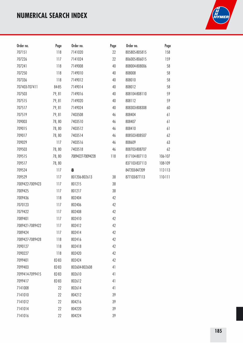
185
NUMERICAL SEARCH INDEX
707151 118
707226 117
707241 118
707250 118
707336 118
707403-707411 84-85
707503 79, 81
707515 79, 81
707517 79, 81
707519 79, 81
709003 78, 80
709015 78, 80
709017 78, 80
709029 117
709503 78, 80
709515 78, 80
709517 78, 80
709524 117
709529 117
7009422-7009423 117
7009425 117
7009436 118
7070123 117
7079422 117
7089401 117
7089421-7089422 117
7089424 117
7089427-7089428 118
7090127 118
7090227 118
7099401 82-83
7099403 82-83
7099414-7099415 82-83
7099417 82-83
7141008 22
7141010 22
7141012 22
7141014 22
7141016 22
7141020 22
7141024 22
7149008 40
7149010 40
7149012 40
7149014 40
7149016 40
7149020 40
7149024 40
7403508 46
7403510 46
7403512 46
7403514 46
7403516 46
7403518 46
70094227-70094228 118
8
801206-802613 38
801215 38
801217 38
802404 42
802406 42
802408 42
802410 42
802412 42
802414 42
802416 42
802418 42
802420 42
802424 42
802604-802608 41
802610 41
802612 41
802614 41
804212 39
804216 39
804220 39
804224 39
805805-805815 158
806005-806015 159
808004-808006 58
808008 58
808010 58
808012 58
808104-808110 59
808112 59
808303-808308 60
808404 61
808407 61
808410 61
808503-808507 62
808609 63
808703-808707 62
817104-807113 106-107
837103-837113 108-109
847203-847209 112-113
877103-877113 110-111
Order no. Page Order no. Page Order no. Page
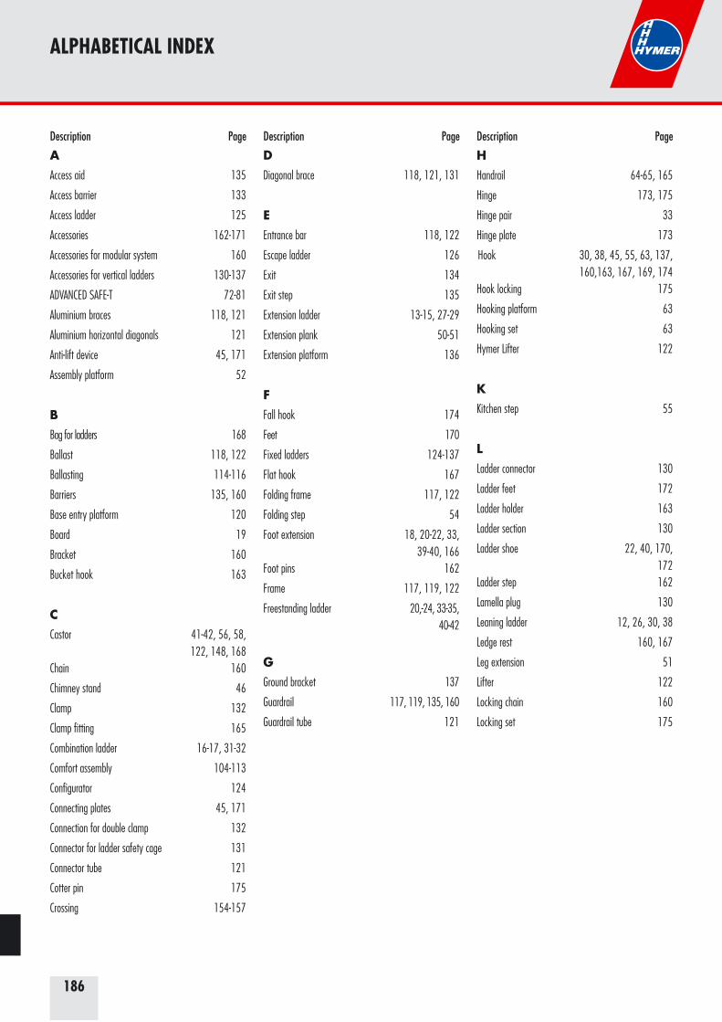
186
ALPHABETICAL INDEX
AAccess aid 135
Access barrier 133
Access ladder 125
Accessories 162-171
Accessories for modular system 160
Accessories for vertical ladders 130-137
ADVANCED SAFE-T 72-81
Aluminium braces 118, 121
Aluminium horizontal diagonals 121
Anti-lift device 45, 171
Assembly platform 52
BBag for ladders 168
Ballast 118, 122
Ballasting 114-116
Barriers 135, 160
Base entry platform 120
Board 19
Bracket 160
Bucket hook 163
CCastor 41-42, 56, 58,
122, 148, 168Chain 160
Chimney stand 46
Clamp 132
Clamp fitting 165
Combination ladder 16-17, 31-32
Comfort assembly 104-113
Configurator 124
Connecting plates 45, 171
Connection for double clamp 132
Connector for ladder safety cage 131
Connector tube 121
Cotter pin 175
Crossing 154-157
DDiagonal brace 118, 121, 131
EEntrance bar 118, 122
Escape ladder 126
Exit 134
Exit step 135
Extension ladder 13-15, 27-29
Extension plank 50-51
Extension platform 136
FFall hook 174
Feet 170
Fixed ladders 124-137
Flat hook 167
Folding frame 117, 122
Folding step 54
Foot extension 18, 20-22, 33, 39-40, 166
Foot pins 162
Frame 117, 119, 122
Freestanding ladder 20,-24, 33-35, 40-42
GGround bracket 137
Guardrail 117, 119, 135, 160
Guardrail tube 121
HHandrail 64-65, 165
Hinge 173, 175
Hinge pair 33
Hinge plate 173
Hook 30, 38, 45, 55, 63, 137, 160,163, 167, 169, 174
Hook locking 175
Hooking platform 63
Hooking set 63
Hymer Lifter 122
KKitchen step 55
LLadder connector 130
Ladder feet 172
Ladder holder 163
Ladder section 130
Ladder shoe 22, 40, 170, 172
Ladder step 162
Lamella plug 130
Leaning ladder 12, 26, 30, 38
Ledge rest 160, 167
Leg extension 51
Lifter 122
Locking chain 160
Locking set 175
Description Page Description Page Description Page
187
ALPHABETICAL INDEX
MMobile towers 68-122
Modular system 138-160
Multipurpose ladder 19
OOnline-configurator 124
Orchard ladder 53
Overlap 132
PPlatform 19, 52, 62-63,
117, 120, 132, 136, 169
Platform ladder 58-61
Platform step 150-153
RRepair sets 176
Rigid safety bar 174
Roof hook 45, 171
Roof ladders 44-46
Roofing products 44-46
Rope 175
Rope pulley 175
Rope-operated ladder 14-15, 28-29
Rubber pad 167
Rung cover set 39, 175
SSAFET SOLUTION 82
Safety cage clamp 131
Safety gate 160
Safety guardrail 117
Safety peg 118, 121
Safety step 54
Safety strap 175
Shoe 22, 40, 170
S-Hook 174
Spare parts 172-176
Spare parts for towers 117-122
Stabiliser 118, 121-122, 164, 172, 174
Stabiliser clamp fitting 121
Stabiliser extension 121
Stairs 120, 142-149, 158-159
Stairway tower 90, 100
Steel fitting 173
Step 54-56, 162
Step stand 56
Stocker's ladder 64-65
Suspension hook 30, 38, 160, 167, 169
TTanker filling ladder 66
Telescopic aluminium plank 51
Telescopic ladder 18, 39
Telesteg 50
Telestep 18, 39
Toeboard 117, 120
Toeboard clip 120
Twister 164
UUniversal foot extension 20, 33, 166
Universal stabiliser 164
VVertical ladders 124-137
W
Wall bracket 137
Wall connector 118
Wall fastening 137
Wall hook 137
Wall protector 167
Wall spacer 163
Wall wheels 167
Wallpapering table 48-49
Wallpapering table extension 49, 170
Window cleaner's ladder 52
Wooden ladder 22, 40, 46
Work platform 62
Description Page Description Page Description Page
188
Hymer-Leichtmetallbau GmbH & Co. KGKäferhofen 10, D-88239 Wangen/Allgäu, Tel. ++49 (0) 7522/700-0, Fax ++49 (0) 7522/[email protected], www.hymer.de