Embed Size (px)
Citation preview

2mm PLANER BN822Y
SAFETY AND OPERATING MANUAL
0.5
0 1
1.5
2.0
0


2mm PLANER BN822Y
GUARANTEE
This product carries a Screwfix Direct Ltd guarantee of 12 months. If your product develops a fault within this period, you should,in the first instance contact Screwfix Direct Ltd on Freephone 0500 41 41 41. If the fault occurs within the first 12 months, you may return the goods for a full refund or we will repair or replace the goods if you prefer. When repair is not practical or identical goods are not available, alternative goods of similar specification and quality will usually be provided but, failing this, you will be offered a partial or full refund depending on the time period since purchase.
This guarantee specifically excludes losses caused due to:- Fair wear and tear- Misuse or abuse- Lack of routine maintenance- Failure of consumable items (such as batteries)- Accidental damage- Cosmetic damage- Failure to follow manufacturer’s guidelines- Loss of use of the goods- Repairs attempted by anyone, unless authorised by Screwfix Direct Ltd.
This guarantee does not affect your statutory rights. This guarantee is only valid in the UK.
For further technical advice, spare parts or repair service (outside of guarantee) please contact the customer helpline number on 0845 607 6380.
Congratulations on your purchase of a power tool from Screwfix Direct Ltd. We want you to continue getting the best performance from it so this handbook includes information on safety, handling and care. Please retain this handbook in case you need to refer to any of the information in the future.
Your power tool comes with a 12-month guarantee,so should it develop a fault within this period contact Screwfix Direct Ltd on Freephone 0500 41 41 41.
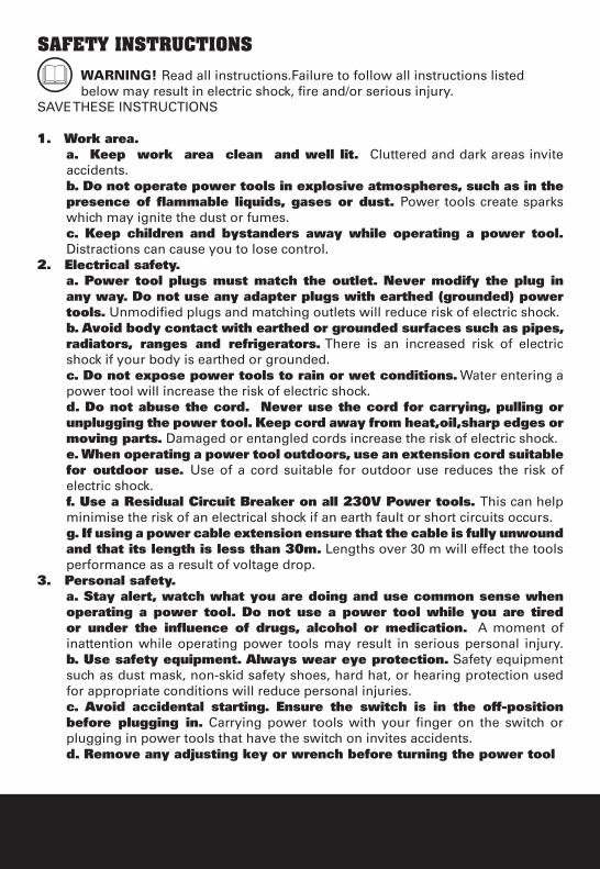
SAFETY INSTRUCTIONSWARNING! Read all instructions.Failure to follow all instructions listed below may result in electric shock, fire and/or serious injury.
SAVE THESE INSTRUCTIONS
1. Work area. a. Keep work area clean and well lit. Cluttered and dark areas invite accidents.b. Do not operate power tools in explosive atmospheres, such as in the presence of flammable liquids, gases or dust. Power tools create sparks which may ignite the dust or fumes.c. Keep children and bystanders away while operating a power tool. Distractions can cause you to lose control.
2. Electrical safety. a. Power tool plugs must match the outlet. Never modify the plug in any way. Do not use any adapter plugs with earthed (grounded) power tools. Unmodified plugs and matching outlets will reduce risk of electric shock.b. Avoid body contact with earthed or grounded surfaces such as pipes, radiators, ranges and refrigerators. There is an increased risk of electric shock if your body is earthed or grounded. c. Do not expose power tools to rain or wet conditions. Water entering a power tool will increase the risk of electric shock.d. Do not abuse the cord. Never use the cord for carrying, pulling or unplugging the power tool. Keep cord away from heat,oil,sharp edges or moving parts. Damaged or entangled cords increase the risk of electric shock.e. When operating a power tool outdoors, use an extension cord suitable for outdoor use. Use of a cord suitable for outdoor use reduces the risk of electric shock.f. Use a Residual Circuit Breaker on all 230V Power tools. This can help minimise the risk of an electrical shock if an earth fault or short circuits occurs.g. If using a power cable extension ensure that the cable is fully unwound and that its length is less than 30m. Lengths over 30 m will effect the tools performance as a result of voltage drop.
3. Personal safety.a. Stay alert, watch what you are doing and use common sense when operating a power tool. Do not use a power tool while you are tired or under the influence of drugs, alcohol or medication. A moment of inattention while operating power tools may result in serious personal injury.b. Use safety equipment. Always wear eye protection. Safety equipment such as dust mask, non-skid safety shoes, hard hat, or hearing protection used for appropriate conditions will reduce personal injuries.c. Avoid accidental starting. Ensure the switch is in the off-position before plugging in. Carrying power tools with your finger on the switch or plugging in power tools that have the switch on invites accidents.d. Remove any adjusting key or wrench before turning the power tool

2mm PLANER BN822Y
on. A wrench or a key left attached to a rotating part of the power tool may result in personal injury.e. Do not overreach. Keep proper footing and balance at all times. This enables better control of the power tool in unexpected situations.f. Dress properly. Do not wear loose clothing or jewellery. Keep your hair, clothing and gloves away from moving parts. Loose clothes, jewellery or long hair can be caught in moving parts.g. If devices are provided for the connection of dust extraction and collection facilities, ensure these are connected and properly used. Use of these devices can reduce dust-related hazards.
4. Power tool use and care.a. Do not force the power tool. Use the correct power tool for your application. The correct power tool will do the job better and safer at the rate for which it was designed.b. Do not use the power tool if the switch does not turn it on and off. Any power tool that cannot be controlled with the switch is dangerous and must be repaired.c. Disconnect the plug from the power source before making any adjustments, changing accessories, or storing power tools. Such preventive safety measures reduce the risk of starting the power tool accidentally.d. Store idle power tools out of the reach of children and do not allow persons unfamiliar with the power tool or these instructions to operate the power tool. Power tools are dangerous in the hands of untrained users.e. Maintain power tools. Check for misalignment or binding of moving parts, breakage of parts and any other condition that may affect the power tools operation. If damaged, have the power tool repaired before use. Poorly maintained power tools cause many accidents.f. Keep cutting tools sharp and clean. Properly maintained cutting tools with sharp cutting edges are less likely to bind and are easier to control.g. Use the power tool, accessories and tool bits etc., in accordance with these instructions and in the manner intended for the particular type of power tool, taking into account the working conditions and the work to be performed. Use of the power tool for operations different from intended could result in a hazardous situation.
5. Service.a. Have your power tool serviced by a qualified repair person using only identical replacement parts. This will ensure that the safety of the power tool is maintained.
HEALTH ADVICEWARNING! When drilling, sanding, sawing or grinding, dust particles will be produced. In some instances, depending on the materials you are working with,
this dust can be particularly harmful to you (e.g. lead from old gloss paint).You are advised to consider the risks associated with the materials you are working with and to reduce the risk of exposure. You should:
- Work in a well-ventilated area.
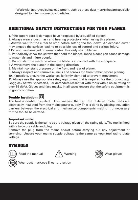
- Work with approved safety equipment, such as those dust masks that are specially designed to filter microscopic particles.
ADDITIONAL SAFETY INSTRUCTIONS FOR YOUR PLANER
1.If the supply cord is damaged have it replaced by a qualified person.2. Always wear a dust mask and hearing protectors when using this planer.3.Always wait for the cutter to stop before setting the tool down. An exposed cutter may engage the surface leading to possible loss of control and serious injury. 4.Do not use damaged or worn blades. Use only sharp blades.5. Periodically check the screws that hold the blades, loose blades can cause damage to materials and injure people.6. Do not start the machine when the blade is in contact with the workpiece. 7. Always move the planer in the cutting direction.8. Maintain constant pressure on the front and rear of planer. 9. Always inspect and remove all nails and screws etc from timber before planing.10. If possible, ensure the workpiece is firmly clamped to prevent movement.11. Always use the appropriate safety equipment that is required for the product. e.g. Goggles / Safety Spectacles, Ear defenders (essential with tools with a noise rating of over 85 dbA), Gloves and face masks. In all cases ensure that the safety equipment is in good condition.
Double insulation:The tool is double insulated. This means that all the external metal parts are electrically insulated from the mains power supply. This is done by placing insulation barriers between the electrical and mechanical components making it unnecessary for the tool to be earthed.
Important note:Be sure the supply is the same as the voltage given on the rating plate. The tool is fitted with a two-core cable and plug.Remove the plug from the mains socket before carrying out any adjustment or servicing. Unsure your mains supply voltage is the same as your tool rating plate voltage.
SYMBOLS
Read the manual Warning Wear gloves
Wear dust mask,eye & ear protection
2mm PLANER BN822Y
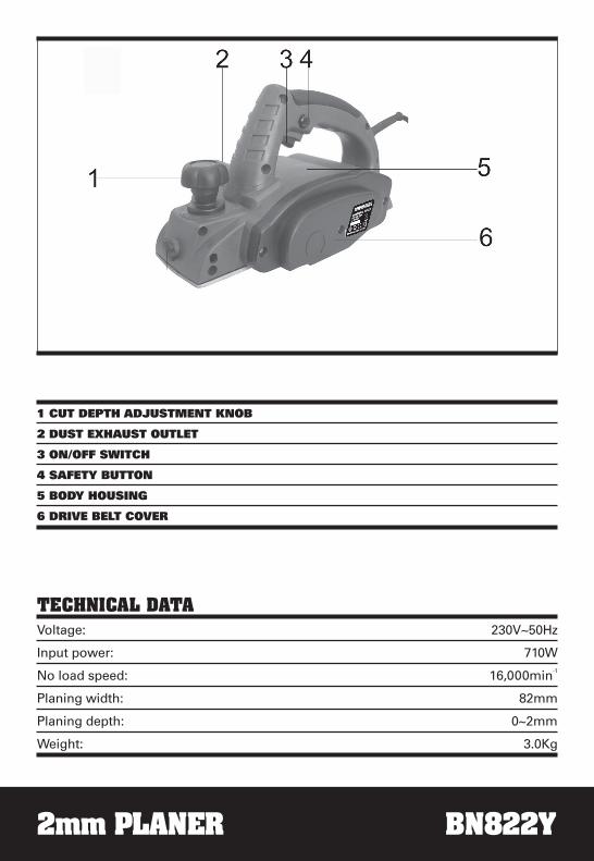
1 CUT DEPTH ADJUSTMENT KNOB
2 DUST EXHAUST OUTLET
3 ON/OFF SWITCH
4 SAFETY BUTTON
5 BODY HOUSING
6 DRIVE BELT COVER
TECHNICAL DATAVoltage: 230V~50Hz
Input power: 710W
No load speed: 16,000min-1
Planing width: 82mm
Planing depth: 0~2mm
Weight: 3.0Kg

ACCESSORIES
Dust bag: 1PCSpare belt: 1PCSpanner: 1pcAllen key: 1pcYour planer requires two 82mm blades and two blades are supplied ready fitted.
NOISE AND VIBRATION DATASound pressure level: 87dB (A)
Sound power level: 100dB (A)
Vibration level: 1.193m/s2
2mm PLANER BN822Y
Fig 4
Fig 5
Fig 3
Fig 2
Fig 6
OPERATING INSTRUCTIONS
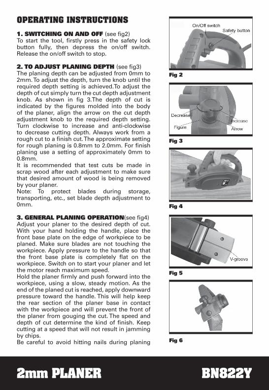
1. SWITCHING ON AND OFF (see fi g2)To start the tool, fi rstly press in the safety lock button fully, then depress the on/off switch. Release the on/off switch to stop.
2. TO ADJUST PLANING DEPTH (see fi g3)The planing depth can be adjusted from 0mm to 2mm. To adjust the depth, turn the knob until the required depth setting is achieved.To adjust the depth of cut simply turn the cut depth adjustment knob. As shown in fi g 3.The depth of cut is indicated by the fi gures molded into the body of the planer, align the arrow on the cut depth adjustment knob to the required depth setting.Turn clockwise to increase and anti-clockwise to decrease cutting depth. Always work from a rough cut to a fi nish cut. The approximate setting for rough planing is 0.8mm to 2.0mm. For fi nish planing use a setting of approximately 0mm to 0.8mm. It is recommended that test cuts be made in scrap wood after each adjustment to make sure that desired amount of wood is being removed by your planer.Note: To protect blades during storage, transporting, etc., set blade depth adjustment to 0mm.
3. GENERAL PLANING OPERATION(see fi g4)Adjust your planer to the desired depth of cut. With your hand holding the handle, place the front base plate on the edge of workpiece to be planed. Make sure blades are not touching the workpiece. Apply pressure to the handle so that the front base plate is completely fl at on the workpiece. Switch on to start your planer and let the motor reach maximum speed.Hold the planer fi rmly and push forward into the workpiece, using a slow, steady motion. As the end of the planed cut is reached, apply downward pressure toward the handle. This will help keep the rear section of the planer base in contact with the workpiece and will prevent the front of the planer from gouging the cut. The speed and depth of cut determine the kind of fi nish. Keep cutting at a speed that will not result in jamming by chips.Be careful to avoid hitting nails during planing
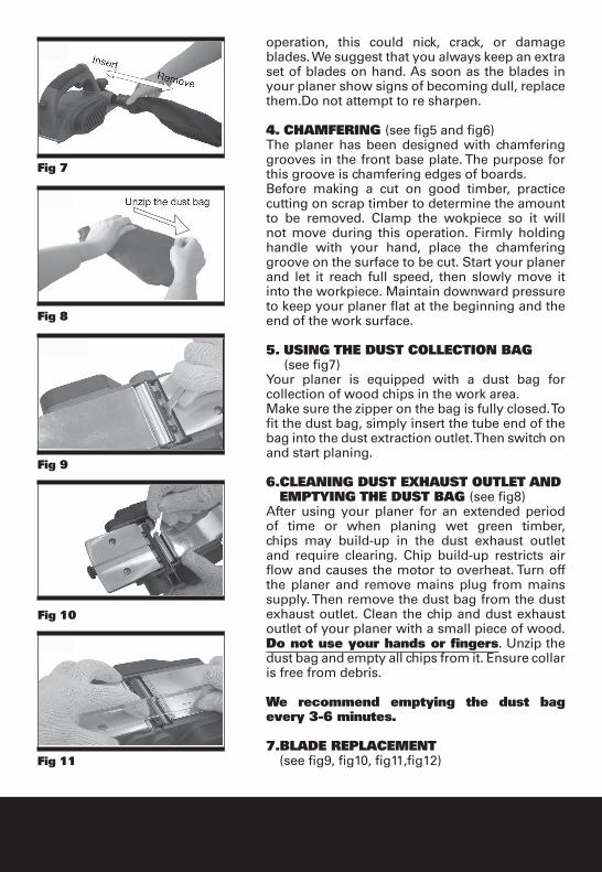
operation, this could nick, crack, or damage blades. We suggest that you always keep an extra set of blades on hand. As soon as the blades in your planer show signs of becoming dull, replace them.Do not attempt to re sharpen.
4. CHAMFERING (see fig5 and fig6) The planer has been designed with chamfering grooves in the front base plate. The purpose for this groove is chamfering edges of boards.Before making a cut on good timber, practice cutting on scrap timber to determine the amount to be removed. Clamp the wokpiece so it will not move during this operation. Firmly holding handle with your hand, place the chamfering groove on the surface to be cut. Start your planer and let it reach full speed, then slowly move it into the workpiece. Maintain downward pressure to keep your planer flat at the beginning and the end of the work surface.
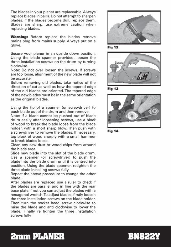
5. USING THE DUST COLLECTION BAG (see fig7)Your planer is equipped with a dust bag for collection of wood chips in the work area. Make sure the zipper on the bag is fully closed. To fit the dust bag, simply insert the tube end of the bag into the dust extraction outlet. Then switch on and start planing.
6.CLEANING DUST EXHAUST OUTLET AND EMPTYING THE DUST BAG (see fig8)After using your planer for an extended period of time or when planing wet green timber, chips may build-up in the dust exhaust outlet and require clearing. Chip build-up restricts air flow and causes the motor to overheat. Turn off the planer and remove mains plug from mains supply. Then remove the dust bag from the dust exhaust outlet. Clean the chip and dust exhaust outlet of your planer with a small piece of wood. Do not use your hands or fingers. Unzip the dust bag and empty all chips from it. Ensure collar is free from debris.
We recommend emptying the dust bag every 3-6 minutes.
7.BLADE REPLACEMENT (see fig9, fig10, fig11,fig12)
Fig 7
Fig 9
Fig 8
Fig 10
Fig 11
2mm PLANER BN822Y
The blades in your planer are replaceable. Always replace blades in pairs. Do not attempt to sharpen blades. If the blades become dull, replace them. Blades are sharp, use extreme caution when replacing blades.
Warning: Before replace the blades remove mains plug from mains supply. Always put on a glove.
Secure your planer in an upside down position. Using the blade spanner provided, loosen the three installation screws on the drum by turning clockwise.Note: Do not over loosen the screws. If screws are too loose, alignment of the new blade will not be accurate.Before removing old blades, take notice of the direction of cut as well as how the tapered edge of the old blades are oriented. The tapered edge of the new blades must be in the same orientation as the original blades.
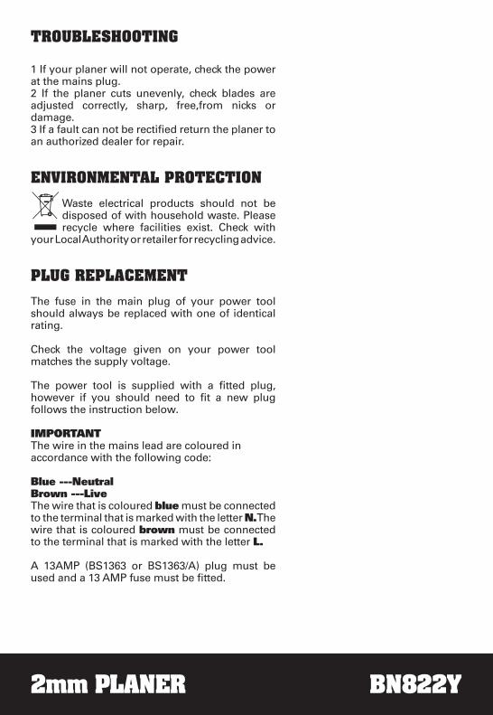
Using the tip of a spanner (or screwdriver) to push blade out of the drum and then remove.Note: If a blade cannot be pushed out of blade drum easily after loosening screws, use a block of wood to break the blade loose from the blade holder, with a short sharp blow. Then push with a screwdriver to remove the blades. If necessary, tap block of wood sharply with a small hammer to break blades loose.Clean any saw dust or wood chips from around the blade area.Slide new blade into the slot of the blade drum. Use a spanner (or screwdriver) to push the blade into the blade drum until it is centred into position. Using the blade spanner, retighten the three blade installing screws fully.Repeat the above procedure to change the other blade. After blades are replaced use a ruler to check if the blades are parallel and in line with the rear base plate.If not you can adjust the blades with a hexagonal wrench. To adjust blades, fi rstly loosen the three installation screws on the blade holder. Then turn the socket head screw clockwise to raise the blade and anti clockwise to lower the blade. Finally re tighten the three installation screws fully
Fig 12
Fig 13
Fig 14
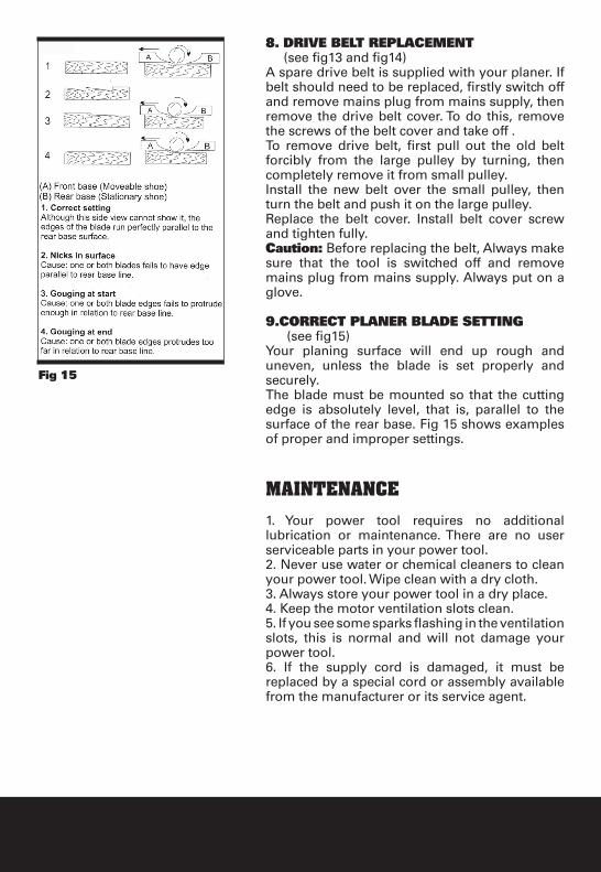
Fig 15
8. DRIVE BELT REPLACEMENT (see fig13 and fig14)A spare drive belt is supplied with your planer. If belt should need to be replaced, firstly switch off and remove mains plug from mains supply, then remove the drive belt cover. To do this, remove the screws of the belt cover and take off .To remove drive belt, first pull out the old belt forcibly from the large pulley by turning, then completely remove it from small pulley.Install the new belt over the small pulley, then turn the belt and push it on the large pulley.Replace the belt cover. Install belt cover screw and tighten fully.Caution: Before replacing the belt, Always make sure that the tool is switched off and remove mains plug from mains supply. Always put on a glove.
9.CORRECT PLANER BLADE SETTING (see fig15)Your planing surface will end up rough and uneven, unless the blade is set properly and securely. The blade must be mounted so that the cutting edge is absolutely level, that is, parallel to the surface of the rear base. Fig 15 shows examples of proper and improper settings.
MAINTENANCE
1. Your power tool requires no additional lubrication or maintenance. There are no user serviceable parts in your power tool.2. Never use water or chemical cleaners to clean your power tool. Wipe clean with a dry cloth.3. Always store your power tool in a dry place.4. Keep the motor ventilation slots clean.5. If you see some sparks flashing in the ventilation slots, this is normal and will not damage your power tool.6. If the supply cord is damaged, it must be replaced by a special cord or assembly available from the manufacturer or its service agent.
2mm PLANER BN822Y
TROUBLESHOOTING
1 If your planer will not operate, check the power at the mains plug.2 If the planer cuts unevenly, check blades are adjusted correctly, sharp, free,from nicks or damage. 3 If a fault can not be rectified return the planer to an authorized dealer for repair.
ENVIRONMENTAL PROTECTION
Waste electrical products should not be disposed of with household waste. Please recycle where facilities exist. Check with
your Local Authority or retailer for recycling advice.
PLUG REPLACEMENT
The fuse in the main plug of your power tool should always be replaced with one of identical rating.
Check the voltage given on your power tool matches the supply voltage.
The power tool is supplied with a fitted plug, however if you should need to fit a new plug follows the instruction below.
IMPORTANT The wire in the mains lead are coloured in accordance with the following code:
Blue ---NeutralBrown ---LiveThe wire that is coloured blue must be connected to the terminal that is marked with the letter N. The wire that is coloured brown must be connected to the terminal that is marked with the letter L.
A 13AMP (BS1363 or BS1363/A) plug must be used and a 13 AMP fuse must be fitted.

13 AMPFUSE
BROWNL (LIVE)
BLUEN (NEUTRAL)
OUTERSLEEVE CABLE GRIP

2mm PLANER BN822Y
Declaration of ConformityWe, Importer
Screwfix Direct LtdMead Avenue
Houndstone Business ParkYeovil
BA 22 8RT
Declare that the productPLANNERBN822Y
Complies with the essential health and safety requirements of the following directives:89/336 EEC, 93/68 EEC.–EMC Directive.
73/23 EEC, 93/68 EEC.–Low Voltage Directive98/37 EC.–Machinery Directive.
Standards and technical specifications referred to:EN 60745-1:2003/+A1:2003
EN 60745-2-14:2003EN 55014-1:2000/+A1:2001/+A2:2002
EN 55014-2:1997/+A1:2001EN 61000-3-2:2000
EN 61000-3-3:1995/+A1:2001
2005
Authorised Signatory
Date: 03/15/05
Signature:
Name: Peter HarriesScrewfix Direct Ltd Quality Manager