Embed Size (px)
Citation preview
WOOD SCREW (6)1/4-20 x 3”
Machine Screw (1)10-24 x 6mm
Machine Screws(3) Wall Anchor (1)
CP115388.07.13
©2013 Liberty Hardware Manufacturing Corporation, A MASCO COMPANY140 Business Park Drive • Winston-Salem, NC 27107www.libertyhardware.com • Made in China/Hecho en China/Fabriqué Chine1-800-542-3789
Safety Bar Installation Instructions
PARTS SUPPLIED:
Phillips Screw Driver
Safety glassesPencil
Drill 1-inch Drill Bit3/16-inch Drill Bit
Stud Finder
1-inch Carbide Tip Drill Bit5/16-inch Carbide Tip Drill Bit
3/8-inch Drive Ratchet
TOOLS REQUIRED:• 3/8-inch Power Drill• 1-inch drill bit or hole saw (carbide tip bit for hard surfaces like Ceramic Tile.• 3/16-inch Drill Bit (to drill pilot hole for installation of Lag screw into wood wall stud)• 5/16-inch Carbide Tip Drill Bit (if drilling through ceramic tile)• 7/16-inch HEX Socket with 3/8-inch Drive Ratchet• #2 Phillips screwdriver• Stud finder• Pencil• Safety glasses
ANCHOR REQUIREMENTS:• Requires a 3 1/2” space behind the wall and works in the following substrates:• 1/2” or 5/8” Drywall (ONLY use on 5/8” drywall for commercial applications)• 1/2” or 5/8” Drywall with Tile• 1/2” or 5/8” Drywall with Marble/Stone
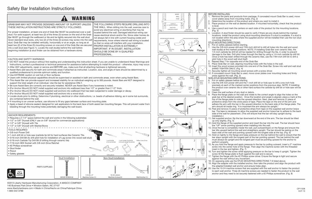
BEFORE INSTALLING:1. Remove the parts and products from package. If concealed mount Grab Bar is used, move
cover plates away from mounting holes. (Fig. 2)2. Determine the location of the product and where you want to install it.3. Place product on the wall at desired location. If mounted horizontally, check that the product
is level.4. Use a pencil and mark the centers on each side of the product for the mounting locations.
(Fig. 3)5. Location: A stud finder should be used to verify if there are any studs behind the marked
locations. Install the product using stud-mounting directions if a stud is available. If a stud is not located within the area where the supplied anchor will be installed then use the non-stud mounting directions.
STUD-MOUNTING DIRECTIONS:6. Put on safety glasses before starting.7. Use the 3/8-inch power drill and 7/64-inch drill bit to drill all holes into the wall and wood
wall stud(s) at the marked positions. NOTE: If installing Grab Bar over ceramic tiles, the 1/4-inch carbide tip drill bit will be needed for drilling through the tile, in order to prevent damage to the tiles. Drill pilot holes through the tiles by using a 1/4-inch carbide tip drill bit. Once a hole has been drilled through the ceramic tiles, use the 7/64-inch drill bit to drill a pilot hole in the wood wall stud itself.
8. Repeat Step 7 for opposite end of the Grab Bar.9. Place Grab Bar on wall, aligning mounting holes with the holes in the wall.10. Insert the wood screws provided into one end of the Grab Bar. Screw into wall and wall stud
(HAND TIGHTEN ONLY). (Fig. 4)11. Securely tighten all mounting wood screws with a screw driver.12. If concealed mount Grab Bar is used, move cover plates over mounting holes and firmly
press against the wall. (Fig. 2)NON-STUD MOUNTING DIRECTIONS:6. Put on safety glasses before starting.7. Use the 3/8-inch power drill and the 1-inch drill bit or hole saw to drill a one-inch hole
precisely at each of the marked center positions from the previous step. NOTE: If installing the product over ceramic tile or other hard surface the carbide tip drill bit or hole saw will be needed.
8. Clean the wall surface of any dust or debris.9. Place the flange plate on the wall and rotate to the correct angle to align the holes on the
grab bar at the desired position. Once the location and angle is aligned, place a mark at the top of the flange plate to note the upward direction. Next, peel and remove (1) piece of protective strips from the circle piece of tape. Place the tape on the end of the arm and adhere the arm with the bar in the upward direction to the back side of the flange plate. The arm should sit inside ring. *It is important the arm always be upright.*
10. Peel and remove (1) piece of protective strips from tape on the supplied wall anchor brace bar. The tape is necessary to allow the supplied wall anchor brace bar to adhere to the back side of the wall for placement. (This will ensure that the bar will stay upright during installation.)
11. Get supplied anchor, flip the bar downward at the end of the arm. The bar should be tilted up only slightly. (Fig. 5)
12. Hold the flange of the supplied anchor and insert the bar into the wall. The bar should have the “UP” arrow pointing upward when installing into the wall.
13. Once the bar is completely inside the wall, pull outward/back on the flange and ensure the bar tilts upward behind the wall and straightens upright. The bar should be resting on the back side of the wall and pointing upward with the longest side at the top. (Fig. 6)
14. Hold on tightly to the flange and keep pressure on the bar behind the wall to ensure that the bar stays upright with the longest part of the bar pointing upward. The bar behind the wall must always be upright and the longest part must be pointing upward for the anchor to perform properly.
15. As you hold the flange and apply pressure to the bar by pulling outward, insert a 3” machine screw into the center hole of the flange. Then align the machine screw with the threaded insert in the bar and tighten. (Fig. 7)
16. Turn and tighten the screw while applying pressure on the bar to keep it upright. Tighten the screw till the flange plate is flush against the wall and is secure.
17. Tighten the flange with the #2 Phillips screw driver. Ensure the flange is tight and secure against the wall without any movement.
18. On opposing side use the STUD-MOUNTING DIRECTIONS 7-9 listed above.19. Align the adapter with the installed anchor, then take the product and align the product with
the adapter/installed wall anchor and ensure holes align.20. Use the 10-24 machine screws that are supplied with the wall anchor to fasten the product
to each wall anchor. Three (3) machine screws are needed to fasten the product to the wall anchor and they need to be securely fastened with a #2 Phillips screwdriver. (Fig. 8)
THE FOLLOWING STEPS REQUIRE DRILLING INTO THE WALL. When drilling into the wall, exercise care to avoid any electrical wiring or plumbing that may be located behind the wall. Damaged electrical wiring can cause electrical shock and/or fire. Since older homes do not always fall in line with current housing codes and requirements, know where internal wall wiring is located so that no wires will interfere with your installation.PROPER INSTALLATION IS EXTREMELY IMPORTANT. IF IN DOUBT, INSTALLATION SHOULD BE DONE BY A QUALIFIED PROFESSIONAL.
GRAB BAR MAY NOT PROVIDE DESIGNED AMOUNT OF SUPPORT UNLESS THESE INSTALLATION INSTRUCTIONS ARE STRICTLY FOLLOWED.
For proper installation, at least one end of Grab Bar MUST be positioned over a wall stud. For solid support, at least two (2) of the three (3) screws on the end of the Grab Bar MUST go through the wallboard or tile and be tightly secured into the wall stud. Given standard stud sizes, only two (2) of the three (3) screws may screw into the wall stud. Grab Bar may be installed vertically, horizontally or at an angle, so long as at least two (2) of the three (3) mounting screws on one end of the Grab Bar are secured into a wall stud (see Figure 1). Locate the wall stud(s) behind the wall before beginning installation (a stud finder can be obtained from a hardware store).
Fig. 3
Fig. 5
Fig. 8
FRONT VIEWVERTICAL MOUNT
FRONT VIEWANGLE MOUNT
WOOD
WALL
STUD
NORMALLY16" CENTER-TO-CENTER
FRONT VIEW
HORIZONTAL MOUNTFig. 1
WALLBOARD
WALLBOARD
Fig. 4
EXPOSED MOUNT GRAB BAR CONCEALED MOUNT GRAB BAR
Fig. 2
Fig. 6
1 2 3
Fig. 7
1 2 3
Flange
Flange
Drywall
WOOD WALL STUD
WOOD WALL STUD
WOOD WALL STUD
TOP VIEWHORIZONTAL MOUNT
GRAB BAR
GRAB BAR
SIDE VIEWVERTICAL MOUNT
WOOD SCREW
Stud Installation Non-Stud Installation
Cover PlateMountingHoles
1 2 3
CAUTION AND SAFETY WARNINGS:• DO NOT install this product without first reading and understanding this instruction sheet. If you are unable to understand these Warnings and Instructions, contact a professional or technical personnel for assistance before attempting to install this product - otherwise, injury may occur.• After ANY adjustments, repair or service and BEFORE use, make sure that all attaching hardware is tightened securely.• Assist Bars add security for bath and commode areas if attached as instructed. Location, size, and angle of bars should be determined by a qualified professional to provide optimum safety and function.• Use EXTREME caution on wet tub or floor surfaces.• Users with limited physical capabilities should be supervised or assisted in bath and commode areas, even when using Assist Bars.• This Assist Bar can provide support and increased stability for an individual weighing up to 300 pounds. Assist Bars are NOT designed to support the total weight of an individual. Use the bar for assistance ONLY.• Be sure Assist Bars are correctly and securely installed. NEVER use Assist Bars if any looseness is noted.• (For Anchor Mount) DO NOT install supplied wall anchors into wallboard less than 1/2” or greater than 2 1/2” thick.• (For Anchor Mount) DO NOT install supplied wall anchors into wallboard that has been subjected to water damage or decay.• (For Anchor Mount) DO NOT install supplied wall anchors into a wood stud.• Locate studs prior to drilling. Determine if plumbing, electrical or other obstructions, i.e. beads of adhesive ribbing, as in some tub surrounds, are contained behind the wall.• If mounting to an uneven surface, use silicone to fill any gaps between surface and mounting plate.• Apply a bead of silicone sealant designed for wet applicators to the back face of both assist bar mounting flanges. This will prevent water from bleeding through the mounting holes potentially damaging the wall board.
VIS À BOIS (6) vis à métaux 1/4-20 de
3 po (7,62 cm) de longueur (1)Vis à métaux
10-24 x 6 mm (3) Ancrage mural (1)
CP115388.07.13
©2013 Liberty Hardware Manufacturing Corporation, A MASCO COMPANY140 Business Park Drive • Winston-Salem, NC 27107www.libertyhardware.com • Made in China/Hecho en China/Fabriqué Chine1-800-542-3789
Instructions d’installation de la bare de sécurité
PIÈCES FOURNIES:
RECOMMANDATIONS POUR LES ANCRAGES :Requiert un espace de 3½ po (8,9 cm) à l'arrière du mur et convient aux supports suivants:• cloison sèche de 1/2 ou 5/8 po (1,27 ou 1,59 cm) (montez UNIQUEMENT sur des cloisons sèches de 5/8 po dans les locaux commerciaux)• cloison sèche de 1/2 ou 5/8 po (1,27 ou 1,59 cm) recouverte de carreaux• cloison sèche de 1/2 ou 5/8 po (1,27 ou 1,59 cm) recouverte de marbre ou de pierre
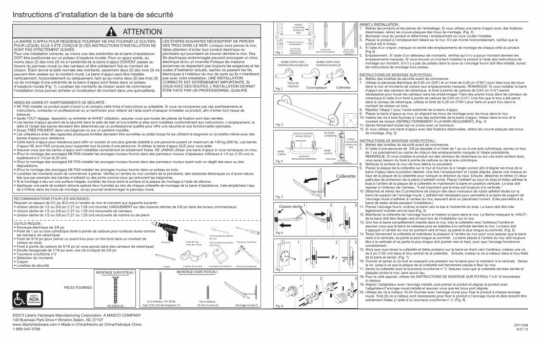
AVANT L'INSTALLATION :1. Retirez les produits et les pièces de l'emballage. Si vous utilisez une barre d'appui avec des fixations
dissimulées, retirez les couvre-plaques des trous de montage. (Fig. 2)2. Munissez-vous du produit et déterminez l'emplacement où vous voulez l'installer. 3. Placez le produit à l'emplacement désiré sur le mur. S'il est monté horizontalement, vérifiez que le
produit est à niveau.4. À l'aide d'un crayon, marquez le centre des emplacements de montage de chaque côté du produit. (Fig 3)5. Emplacement : À l'aide d'un détecteur de montants, vérifiez qu'il n'y a aucun montant derrière les
emplacements marqués. Si vous trouvez un montant installez le produit à l'aide des instructions de montage sur montant. S'il n'y a pas de poteau dans la zone où l'ancrage fourni doit être installé, suivez les instructions de montage hors poteau.
INSTRUCTIONS DE MONTAGE SUR POTEAU:6. Mettez des lunettes de sécurité avant de commencer. 7. Utilisez la perceuse électrique de 0,95 cm (3/8") et un foret de 0,28 cm (7/64") pour faire tous les trous
dans le mur et montants de cloison aux emplacements marqués. REMARQUE: Si vous installez la barre d'appui sur des carreaux de céramique, le foret à pointe de carbure de 0,64 cm (1/4") seront nécessaires pour trouer les carreaux sans les endommager. Faire des avants trous dans les carreaux de céramique à l'aide d'un foret à pointe de carbure de 0,64 cm (1/4"). Une fois que le trou a été percé dans le carreau de céramique, utilisez le foret de 0,28 cm (7/64") pour faire un avant trou dans le montant de cloison en bois.
8. Répétez l'étape 7 pour l'autre extrémité de la barre d'appui.9. Placez la barre d'appui au mur, en alignant les trous de montage avec les trous dans le mur.10. Insérez les vis à bois fournies à l'une des extrémités de la barre d'appui. Vissez dans le mur et le
montant de cloison (SERREZ FERMEMENT À LA MAIN SEULEMENT). (Fig. 4)11. Serrez fermement toutes les vis à bois avec un tournevis.12. Si vous utilisez une barre d'appui avec des fixations dissimulées, retirez les couvre-plaques des trous
de montage. (Fig. 2)
INSTRUCTIONS DE MONTAGE HORS POTEAU :6. Mettez des lunettes de sécurité avant de commencer. 7. À l'aide d'une perceuse de 3/8 po équipée d'un foret de 1 po ou d'une scie cylindrique, percez un trou
de 1 po précisément au centre de chacun des emplacements marqués à l'étape précédente. REMARQUE: Si vous installez le produit sur des carreaux de céramique ou sur une autre surface dure, vous aurez besoin du foret à pointe de carbure ou de la scie cylindrique.
8. Nettoyez la surface du mur de tous débris ou poussière.9. Placez la plaque de la collerette sur le mur et tournez-la à l'angle correct afin d'aligner les trous de la
barre d'appui dans la position désirée. Une fois l'emplacement et l'angle alignés, placez une marque en haut de la plaque de la collerette pour indiquer la direction du haut. Ensuite, détachez et retirez (1) deux pellicules de protection de la pièce d'adhésif ronde. Placez l'adhésif au bout du bras et faites adhérer le bras à l'arrière de la plaque de la collerette en maintenant la barre en position verticale. Le bras doit reposer à l'intérieur de l'anneau. *Il est important que le bras soit toujours à la verticale.*
10. Détachez et retirez les (1) protections de chacun des deux morceaux de ruban adhésif situés sur la barre de support de l'ancrage mural. L'adhésif est nécessaire pour permettre à la barre de support de l'ancrage mural d'adhérer à l'arrière du mur, assurant ainsi un placement correct. (Cela permettra à la barre de rester droite pendant l'installation.)
11. Prenez l'ancrage fourni, inclinez la barre vers le bas à l'extrémité du bras. La barre doit être très légèrement inclinée vers le haut (Fig. 5)
12. Maintenez la collerette de l'ancrage fourni et insérez la barre dans le mur. La flèche indiquant le «HAUT» de la barre doit être dirigée vers le haut lors de l'installation sur le mur.
13. Une fois la barre complètement insérée dans le mur, tirez la collerette vers l'extérieur/l'arrière et assurez-vous que la barre se redresse puis se stabilise à la verticale derrière le mur. La barre doit s'appuyer à l'arrière du mur en pointant vers le haut, sa partie la plus longue au sommet. (Fig. 6)
14. Tenez fermement la collerette et maintenez la pression à l'arrière du mur pour vous assurer que la barre reste à la verticale, sa partie la plus longue au sommet. La barre placée à l'arrière du mur doit toujours être à la verticale et sa partie la plus longue doit pointer vers le haut, pour que l'ancrage fonctionne correctement.
15. Alors que vous tenez la collerette et faites pression sur la barre en tirant vers l'extérieur, insérez une vis de 3 po (7,62 cm) dans le trou central de la collerette. Ensuite, insérez la vis à métaux dans le trou fileté de la barre et serrez. (Fig. 7)
16. Tournez et serrez la vis tout en exerçant une pression sur la barre pour la maintenir à la verticale. Serrez la vis jusqu'à ce que la plaque de la collerette soit fermement placée à fleur du mur.
17. Serrez la collerette avec le tournevis cruciforme n° 2. Assurez-vous que la collerette est bien serrée et plaquée contre le mur, sans aucun jeu.
18. Pour le côté opposé, utilisez les INSTRUCTIONS DE MONTAGE SUR POTEAU 7 à 9-10 énumérées ci-dessus.
19. Alignez l'adaptateur avec l'ancrage installé, puis prenez le produit et alignez le produit avec l'adaptateur/l'ancrage mural installé et assurez-vous que les trous sont alignés.
20. Utilisez les vis à métaux 10-24 fournies avec l'ancrage mural pour fixer le produit à chaque ancrage mural. Trois (3) vis à métaux sont nécessaires pour fixer le produit à l'ancrage mural et elles doivent être solidement fixées à l'aide d'un tournevis cruciforme n° 2. (Fig. 8)
LES ÉTAPES SUIVANTES NÉCESSITENT DE PERCER DES TROU DANS LE MUR. Lorsque vous percez le mur, faites attention d'éviter tout conduit électrique ou plomberie qui pourraient se trouver derrière le mur. Des fils électriques endommagés peuvent provoquer un choc électrique et/ou un incendie Puisque les maisons anciennes ne respectent pas toujours les exigences et les codes d'habitation actuels, sachez où passent les fils électriques à l'intérieur du mur de sorte qu'ils n'interfèrent pas avec votre installation. UNE INSTALLATION CORRECTE EST EXTRÊMEMENT IMPORTANTE. SI VOUS AVEZ DES DOUTES, L'INSTALLATION DEVRAIT ÊTRE FAITE PAR UN PROFESSIONNEL QUALIFIÉ.
LA BARRE D'APPUI POUR RÉSIDENCE POURRAIT NE PAS FOURNIR LE SOUTIEN POUR LEQUEL ELLE A ÉTÉ CONÇUE SI CES INSTRUCTIONS D'INSTALLATION NE SONT PAS STRICTEMENT SUIVIES.Pour une installation correcte, au moins une des extrémités de la barre d'assistance DOIT être positionnée sur un poteau d'ossature murale. Pour un appui solide, au moins deux (2) des trois (3) vis à l'extrémité de la barre d'appui DOIVENT passer au travers du panneau mural ou des carreaux et être solidement fixé au montant de cloison. Étant donné la taille normale des montants, seulement deux (2) des trois (3) vis peuvent être vissées sur le montant mural. La barre d'appui peut être installée verticalement, horizontalement ou obliquement, tant qu'au moins deux (2) des trois (3) vis de montage d'une extrémité de la barre d'appui sont fixées dans un poteau d'ossature murale (Fig. 1). Localisez les montants de cloison avant de commencer l'installation (vous pouvez acheter un localisateur de montant dans une quincaillerie).
Fig. 3
Fig. 5
Fig. 8
PANNEAU MURAL
PANNEAU MURAL
Fig. 4
Fig. 2
Fig. 6
1 2 3
Fig. 7
1 2 3
Collerette
ColleretteCouvreplaque
Cloison sèche
POTEAU D'OSSATURE MURALE EN BOIS
POTEAU D'OSSATURE MURALE EN
BOIS
VUE DE FACE INSTALLATION HORIZONTALE
BARRE D'APPUI
BARRE D'APPUI
VUE LATÉRALE INSTALLATION VERTICALE
VIS À BOIS SUPÉRIEURE
MONTAGE SUR POTEAU : MONTAGE HORS POTEAU :
MISES EN GARDE ET AVERTISSEMENTS DE SÉCURITÉ :• NE PAS installer ce produit avant d'avoir lu et compris cette fiche d'instructions au préalable. Si vous ne comprenez pas ces avertissements et instructions, contactez un professionnel ou un technicien pour obtenir de l'aide avant d'essayer d'installer ce produit, afin d'éviter tout risque de blessure. • Après TOUT réglage, réparation ou entretien et AVANT utilisation, assurez-vous que toutes les pièces de fixation sont bien serrées.• Les barres d'appui ajoutent de la sécurité dans la salle de bain et à la toilette si elles sont installées conformément aux instructions. L'emplacement, la taille et l'angle des barres devraient être déterminés par un professionnel qualifié pour offrir une sécurité et une fonctionnalité optimales.• Soyez TRÈS PRUDENT dans une baignoire ou sur un parterre mouillés.• Les utilisateurs avec des capacités physiques limitées devraient être surveillés ou aidés lorsqu'ils les utilisent la baignoire ou la toilette même avec des barres d'appui pour résidence.• Cette barre d'appui pour résidence peut offrir un soutien et une plus grande stabilité à une personne pesant un maximum de 136 kg (300 lb). Les barres d'appui NE sont PAS conçues pour supporter tout le poids d'une personne. N'utilisez la barre d'appui QUE pour vous aider.• Assurez-vous que les barres d'appui sont installées correctement et solidement fixées. NE JAMAIS utiliser une barre d'appui si vous remarquez un mou.• (Pour le montage des ancrages) NE PAS installer les ancrages muraux fournis dans des panneaux muraux d'épaisseur inférieure à 1/2 po (1,35 cm) ou supérieure à 2-1/2 po (6,35 cm). • (Pour le montage des ancrages) NE PAS installer les ancrages muraux fournis dans des panneaux muraux ayant subi un dégât des eaux ou des dégradations.• (Pour le montage des ancrages) NE PAS installer les ancrages muraux fournis dans un poteau en bois.• Localisez les montants avant de commencer à percer. Vérifiez si l'arrière du mur contient de la plomberie, des obstacles électriques ou d'autre nature, tels que par exemple des bandes d'adhésif ou des joints comme ceux qui entourent les baignoires. • Si le montage a lieu sur une surface inégale, comblez les trous entre la surface et la plaque de montage à l'aide de silicone. • Appliquez une perle de scellant silicone spécial lieux humides au dos de chaque collerette de montage de la barre d'assistance. Cela empêchera l'eau de s'infiltrer dans les trous de montage, ce qui pourrait endommager le panneau mural.
OUTILS REQUIS :• Perceuse électrique de 3/8 po• Foret de 1 po ou scie cylindrique (foret à pointe de carbure pour surfaces dures comme les carreaux de céramique) • Foret de 3/16 po (pour percer un avant-trou pour un tire-fond dans un montant de cloison en bois)• Foret à pointe de carbure de 5/16 po (si vous percez dans des carreaux de céramique)• Douille hexagonale de 7/16 po avec une clé à cliquet de 3/8 po• Tournevis cruciforme n°2• Détecteur de montants• Crayon• Lunettes de sécurité
Tournevis cruciforme
Lunettes de sécuritéCrayon
Perceuse Foret de 1 poForet de 3/16 po
Localisateur de montant 3/8-inch Drive Ratchet
Foret à pointe de carbure de 1 po
Foret à pointe de carbure de 5/16 po
ATTENTION
BARRE D'APPUI AVEC FIXATION DISSIMULÉE
BARRE D'APPUI AVEC FIXATION NON DISSIMULÉE
TROUS DEFIXATION
Fig. 1
POTEAU D'OSSATURE MURALE EN
BOIS
VUE DE FACE INSTALLATION HORIZONTALE
VUE DE FACEINSTALLATION OBLIQUE
VUE DE FACE INSTALLATION
VERTICALE
ENTRAXE DE 40,64 cm NORMALEMENT
1 2 3
TORNILLO PARA MADERA (6)tornillos maquinados
de ¼-20 de 3" de largo (1)Tornillo para metales
10-24 x 6 mm (3) Anclaje de pared (1)
CP115388.07.13
©2013 Liberty Hardware Manufacturing Corporation, A MASCO COMPANY140 Business Park Drive • Winston-Salem, NC 27107www.libertyhardware.com • Made in China/Hecho en China/Fabriqué Chine1-800-542-3789
Instrucciones de instalación de la barra de seguridad
PIEZAS SUMINISTRADAS:
REQUERIMIENTOS DEL ANCLAJE:Requiere un espacio de 8,9 cm (3½ pulgadas) detrás de la pared y se puede utilizar con los siguientes materiales:• 1/2” or 5/8” Drywall (ONLY use on 5/8” drywall for commercial applications)• 1/2” or 5/8” Drywall with Tile• 1/2” or 5/8” Drywall wit Marble/Stone
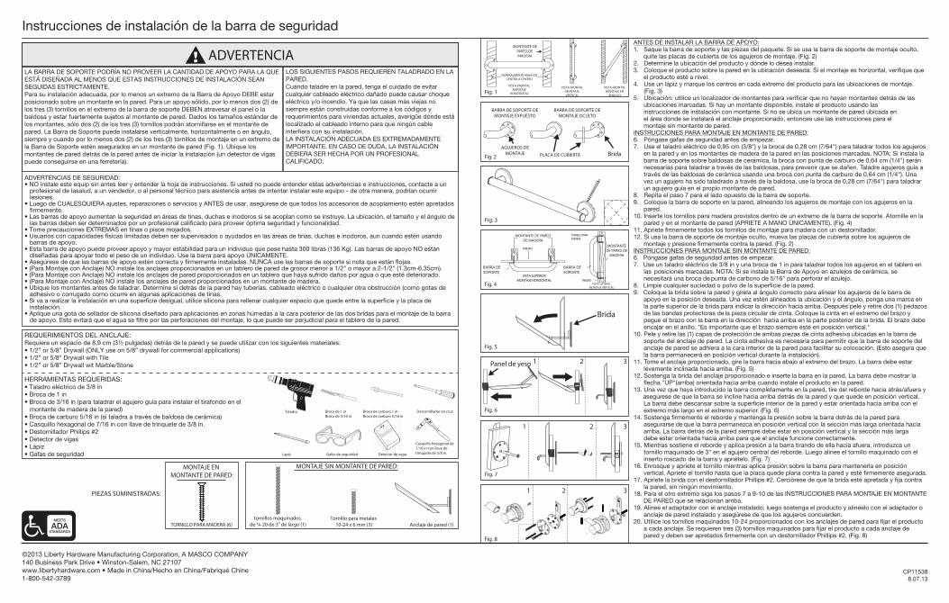
ANTES DE INSTALAR LA BARRA DE APOYO:1. Saque la barra de soporte y las piezas del paquete. Si se usa la barra de soporte de montaje oculto,
quite las placas de cubierta de los agujeros de montaje. (Fig. 2)2. Determine la ubicación del producto y dónde lo desea instalar.3. Coloque el producto sobre la pared en la ubicación deseada. Si el montaje es horizontal, verifique que
el producto esté a nivel.4. Use un lápiz y marque los centros en cada extremo del producto para las ubicaciones de montaje. (Fig. 3)5. Ubicación: utilice un localizador de montantes para verificar que no hayan montantes detrás de las
ubicaciones marcadas. Si hay un montante disponible, instale el producto usando las instrucciones de instalación con montante. Si no se ubica un montante de pared ubicada en el área donde se instalará el anclaje proporcionado, entonces use las instrucciones para el montaje sin montante de pared.
INSTRUCCIONES PARA MONTAJE EN MONTANTE DE PARED:6. Póngase gafas de seguridad antes de empezar.7. Use el taladro eléctrico de 0,95 cm (3/8") y la broca de 0,28 cm (7/64") para taladrar todos los agujeros
en la pared y en los montantes de madera de la pared en las posiciones marcadas. NOTA: Si instala la barra de soporte sobre baldosas de cerámica, la broca con punta de carburo de 0,64 cm (1/4") serán necesarias para taladrar a través de las baldosas, para prevenir que se dañen. Taladre agujeros guía a través de las baldosas de cerámica usando una broca con punta de carburo de 0,64 cm (1/4"). Una vez un agujero ha sido taladrado a través de la baldosa, use la broca de 0,28 cm (7/64") para taladrar un agujero guía en el propio montante de pared.
8. Repita el paso 7 para el lado opuesto de la barra de soporte.9. Coloque la barra de soporte en la pared, alineando los agujeros de montaje con los agujeros en la
pared.10. Inserte los tornillos para madera provistos dentro de un extremo de la barra de soporte. Atornille en la
pared y en el montante de pared (APRIETE A MANO ÚNICAMENTE). (Fig. 4)11. Apriete firmemente todos los tornillos de montaje para madera con un destornillador.12. Si usa la barra de soporte de montaje oculto, mueva las placas de cubierta sobre los agujeros de
montaje y presione firmemente contra la pared. (Fig. 2)INSTRUCCIONES PARA MONTAJE SIN MONTANTE DE PARED:6. Póngase gafas de seguridad antes de empezar.7. Use un taladro eléctrico de 3/8 in y una broca de 1 in para taladrar todos los agujeros en el tablero en
las posiciones marcadas. NOTA: Si se instala la Barra de Apoyo en azulejos de cerámica, se necesitará una broca de punta de carbono de 5/16" para perforar el azulejo.
8. Limpie cualquier suciedad o polvo de la superficie de la pared.9. Coloque la brida sobre la pared y gírela al ángulo correcto para alinear los agujeros de le barra de
apoyo en la posición deseada. Una vez estén alineados la ubicación y el ángulo, ponga una marca en la parte superior de la brida para indicar la dirección hacia arriba. Después pele y retire dos (1) pedazos de las bandas protectoras de la pieza circular de cinta. Coloque la cinta en el extremo del brazo y pegue el brazo con la barra en la dirección hacia arriba en la parte posterior de la brida. El brazo debe encajar en el anillo. *Es importante que el brazo siempre esté en posición vertical.*
10. Pele y retire las (1) capas de protección de ambas piezas de cinta adhesiva ubicadas en la barra de soporte del anclaje de pared. La cinta adhesiva es necesaria para permitir que la barra de soporte del anclaje de pared se adhiera a la cara interior de la pared para facilitar su colocación. (Esto asegura que la barra permanecerá en posición vertical durante la instalación).
11. Tome el anclaje proporcionado, gire la barra hacia abajo al extremo del brazo. La barra debe estar levemente inclinada hacia arriba. (Fig. 5)
12. Sostenga la brida del anclaje proporcionado e inserte la barra en la pared. La barra debe mostrar la flecha "UP"(arriba) orientada hacia arriba cuando instale el producto en la pared.
13. Una vez que haya introducido la barra completamente en la pared, tire del reborde hacia atrás/afuera y asegúrese de que la barra se incline hacia arriba detrás de la pared y que quede en posición vertical. La barra debe descansar sobre la superficie interior de la pared y estar orientada hacia arriba con el extremo más largo en el extremo superior. (Fig. 6)
14. Sostenga firmemente el reborde y mantenga la presión sobre la barra detrás de la pared para asegurarse de que la barra permanezca en posición vertical con la sección más larga orientada hacia arriba. La barra detrás de la pared siempre debe estar en posición vertical y la sección más larga debe estar orientada hacia arriba para que el anclaje funcione correctamente.
15. Mientras sostiene el reborde y aplica presión a la barra tirando de ella hacia afuera, introduzca un tornillo maquinado de 3" en el agujero central del reborde. Luego alinee el tornillo maquinado con el inserto roscado de la barra y apriételo. (Fig. 7)
16. Enrosque y apriete el tornillo mientras aplica presión sobre la barra para mantenerla en posición vertical. Apriete el tornillo hasta que la placa quede plana contra la pared y esté firmemente asegurada.
17. Apriete la brida con el destornillador Phillips #2. Cerciórese de que la brida esté apretada y fija contra la pared, sin ningún movimiento.
18. Para el otro extremo siga los pasos 7 a 9-10 de las INSTRUCCIONES PARA MONTAJE EN MONTANTE DE PARED que se relacionan arriba.
19. Alinee el adaptador con el anclaje instalado; luego sostenga el producto y alinéelo con el adaptador o anclaje de pared instalado y asegúrese de que los agujeros concuerden.
20. Utilice los tornillos maquinados 10-24 proporcionados con los anclajes de pared para fijar el producto a cada anclaje. Se requieren tres (3) tornillos maquinados para fijar el producto a cada anclaje de pared y deben ser apretados firmemente con un destornillador Phillips #2. (Fig. 8)
LOS SIGUIENTES PASOS REQUIEREN TALADRADO EN LA PARED.Cuando taladre en la pared, tenga el cuidado de evitar cualquier cableado eléctrico dañado puede causar choque eléctrico y/o incendio. Ya que las casas más viejas no siempre están construidas conforme a los códigos y requerimientos para viviendas actuales, averigüe dónde está localizado el cableado interno para que ningún cable interfiera con su instalación.LA INSTALACIÓN ADECUADA ES EXTREMADAMENTE IMPORTANTE. EN CASO DE DUDA, LA INSTALACIÓN DEBIERA SER HECHA POR UN PROFESIONAL CALIFICADO.
LA BARRA DE SOPORTE PODRÍA NO PROVEER LA CANTIDAD DE APOYO PARA LA QUE ESTÁ DISEÑADA AL MENOS QUE ESTAS INSTRUCCIONES DE INSTALACIÓN SEAN SEGUIDAS ESTRICTAMENTE.Para su instalación adecuada, por lo menos un extremo de la Barra de Apoyo DEBE estar posicionado sobre un montante en la pared. Para un apoyo sólido, por lo menos dos (2) de los tres (3) tornillos en el extremo de la barra de soporte DEBEN atravesar el panel o la baldosa y estar fuertemente sujetos al montante de pared. Dados los tamaños estándar de los montantes, sólo dos (2) de los tres (3) tornillos podrán atornillarse en el montante de pared. La Barra de Soporte puede instalarse verticalmente, horizontalmente o en ángulo, siempre y cuando por lo menos dos (2) de los tres (3) tornillos de montaje en un extremo de la Barra de Soporte estén asegurados en un montante de pared (Fig. 1). Ubique los montantes de pared detrás de la pared antes de iniciar la instalación (un detector de vigas puede conseguirse en una ferretería).
MONTAJE EN MONTANTE DE PARED:
MONTAJE SIN MONTANTE DE PARED:
ADVERTENCIAS DE SEGURIDAD:• NO instale este equip sin antes leer y entender la hoja de instrucciones. Si usted no puede entender estas advertencias e instrucciones, contacte a un profesional de lasalud, a un vendedor, o al personal técnico para asistencia antes de intentar instalar este equipo - de otra manera, podrían ocurrir lesiones.• Luego de CUALESQUIERA ajustes, reparaciones o servicios y ANTES de usar, asegúrese de que todos los accesorios de acoplamiento estén apretados firmemente.• Las barras de apoyo aumentan la seguridad en áreas de tinas, duchas e inodoros si se acoplan como se instruye. La ubicación, el tamaño y el ángulo de las barras deben ser determinados por un profesional calificado para proveer óptima seguridad y funcionalidad.• Tome precauciones EXTREMAS en tinas o pisos mojados.• Usuarios con capacidades físicas limitadas deben ser supervisados o ayudados en las áreas de tinas, duchas e inodoros, aun cuando estén usando barras de apoyo.• Esta barra de apoyo puede proveer apoyo y mayor estabilidad para un individuo que pese hasta 300 libras (136 Kg). Las barras de apoyo NO están diseñadas para apoyar todo el peso de un individuo. Use la barra para apoyo ÚNICAMENTE.• Asegúrese de que las barras de apoyo estén correcta y firmemente instaladas. NUNCA use las barras de soporte si nota que están flojas.• (Para Montaje con Anclaje) NO instale los anclajes proporcionados en un tablero de pared de grosor menor a 1/2" o mayor a 2-1/2" (1.3cm-6.35cm).• (Para Montaje con Anclaje) NO instale los anclajes de pared proporcionados en un tablero que haya sufrido daños por agua o que esté deteriorado.• (Para Montaje con Anclaje) NO instale los anclajes de pared proporcionados en un montante de madera.• Ubique los montantes antes de taladrar. Determine si detrás de la pared hay tuberías, cableado eléctrico o cualquier otra obstrucción (como gotas de adhesivo o corrugado como ocurre en algunas aplicaciones de tinas.• Si va a realizar la instalación en una superficie desigual, utilice silicona para rellenar cualquier espacio que quede entre la superficie y la placa de instalación.• Aplique una gota de sellador de silicona diseñado para aplicaciones en zonas húmedas a la cara posterior de las dos bridas para el montaje de la barra de apoyo. Esto evitará que el agua se filtre por las perforaciones del montaje, lo que puede ser perjudicial para el tablero de la pared.
Destornillador en cruz
Gafas de seguridadLapiz
Taladro Broca de 1 inBroca de 3/16 in
Detector de vigas
Broca de carburo 1 inBroca de carburo 5/16 in
Casquillo hexagonal de7/16 in con llave detrinquete de 3/8 in.
HERRAMIENTAS REQUERIDAS:• Taladro eléctrico de 3/8 in• Broca de 1 in• Broca de 3/16 in (para taladrar el agujero guía para instalar el tirafondo en el montante de madera de la pared)• Broca de carburo 5/16 in (si taladra a través de baldosa de cerámica)• Casquillo hexagonal de 7/16 in con llave de trinquete de 3/8 in.• Destornillador Phillips #2• Detector de vigas• Lápiz• Gafas de seguridad
ADVERTENCIA
Fig. 3
Fig. 7
1 2 3
Fig. 5
Brida
Fig. 6
1 2 3Panel de yeso
Fig. 1
MONTANTE DE PARED DE MADERA
VISTA FRONTALMONTAJE
HORIZONTAL
VISTA FRONTALMONTAJE EN
ÁNGULO
VISTA FRONTALMONTAJE VERTICAL
NORMALMENTE 40,64 CM CENTRO A CENTRO
Fig. 2 Brida
BARRA DE SOPORTE DE MONTAJE OCULTO
BARRA DE SOPORTE DE MONTAJE EXPUESTO
AGUJEROS DEMONTAJE PLACA DE CUBIERTA
TABLERO
TABLERO
Fig. 4
MONTANTE DE PARED DE MADERA
MONTANTE DE PARED DE
MADERA
VISTA SUPERIORMONTAJE HORIZONTAL
BARRA DE SOPORTE
BARRA DE SOPORTE
VISTA LATERALMONTAJE VERTICAL
TORNILLO PARAMADERA
Fig. 8
1 2 3