Embed Size (px)
Citation preview
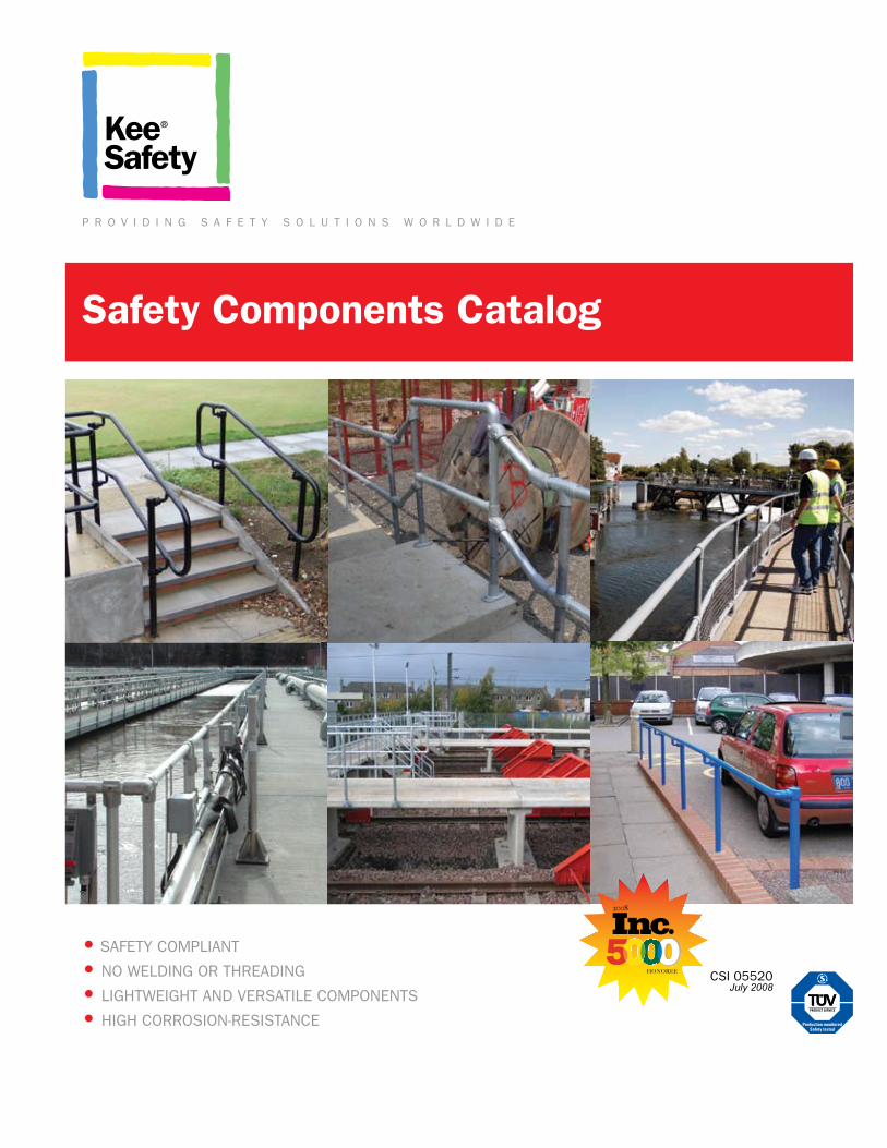
Safety Components Catalog
• safety compliant
• no welding or threading
• lightweight and versatile components
• high corrosion-resistance
csi 05520July 2008
p r o v i d i n g s a f e t y s o l u t i o n s w o r l d w i d e
2008
HONOREE
solutions
SafetyKee safety regularly monitors all new safety standards and directives to ensure the highest levels of safety. Kee safety understands the re-quirements laid out in today’s numerous safety bulletins: osha, iBc u.s. coast guard, ontario Building code, ansi, health and safety, eu direc-tives & cdm regulations to name just a few. either in the factory, on the construction site, or along the ada ramp, Kee safety solutions not only meet but exceed the current safety requirements for maximum protection.
QualityQuality is the overriding priority when manufacturing Kee safety components. it begins in the foundry where all fittings are manufac-tured and galvanized to iso standard Bs en iso 1461 and subject to stringent inspection upon completion. the components are tüv certified for strength, manufacturing quality and consistency.
Solutionsfrom simple protection for loading docks or walkways, to safety railings in aggressive coastal environments or the protection of road bridges and culverts, Kee safety can provide a strategic integrated safety solution to meet your safety requirements with absolute confidence.
Kee safety has been building and designing railings and the components used to create
rugged pipe structures for over 75 years. the simplicity in the design of these systems
is due to the modularity of its parts. whether you need to protect people, equipment,
or your on-site inventory, Kee safety provides the most cost effective safe solutions to
your barrier requirements. when you need a safe, reliable, durable and versatile barrier
system, there is only one company to think of: Kee safety.
railingsafetypre-galvanized cast iron
fittings for the construction of
steel tubular structures
components manufactured from
a high grade Aluminum Silicon
Magnesium Alloy for creating
lightweight tubular structures
barrier railing system designed
to meet ADA (Americans with
Disabilities Act) requirements
2 Safety Components Catalog
contentsTechnical & Specifying
Information
04
Kee Klamp Components
06
Kee lITe Components
24
Kee aCCeSS Components
32
accessories
36
pipe Choices
37
Building Compliant Railings
38
assembly and Installation
40
load Tables
44
Vibration Test
47
Gallery
48
Fax Inquiry Sheet
50
Kee pRojeCTS
51
USA 800.851.5181 CN 877.505.5003 3
tech + spec
pipe referencecomponent
inner dia (in.)nominal bore (in.) pipe outer dia (in.) tube outer dia (in.)
2 0.59 1/4 0.540 0.531
3 0.76 3/8 0.675 0.688
4 0.87 1/2 0.840 0.844
5 1.09 3/4 1.050 1.000
6 1.38 1 1.315 1.313
7 1.72 1-1/4 1.660 1.625
8 1.94 1-1/2 1.900 1.875
9 2.41 2 2.375 2.375
pipe for your StructureKee Klamp safety components are produced in a range of standard sizes to suit schedule 40 steel pipe, sizes 1/4” nominal bore to 2” nominal bore; also equivalent sizes of tubing in other materials.tubing of other specifications can be used, providing the outside diameter is compatible with schedule 40 pipe. pipe with a wall thickness of less than 1/8” can only be used in lightly loaded structure.
4 Safety Components Catalog
Galvanized Steelschedule 40 and schedule 80; size 1/4” to
2” ips; nominal mill lengths of 21’ cut to your
projects’ exact length requirements
powder Coatingdurable, corrosion preventing polyester coating
applied to already galvanized/anodized prod-
ucts; available in any ral color
aluminumalloy 6105-t5 with an anodized finish; size
range 3/4” to 2” ips; nominal mill lengths of
12’ and 24’ cut to your projects’ exact length
requirements
antimicrobial Coatingdefense against the growth of potentially harm-
ful invisible bacteria and fungi; this powder
coating can be applied in a wide range of ral
colors
Note:Kee Safety can provide general guidance on the use of the fittings detailed in
this catalog. However, the nature of the product means that the ultimate responsi-bility for selecting the correct fitting for an application rests with the customer.the customer should also ensure that any existing structure to which a Kee
Safety component is being secured is of sufficient strength to support both the weight of the Kee Safety construction and the imposed loads applied, including
wind loads, snow loads, and any other superimposed loads.
TÜV approvalKee safety components
are approved by tüv, eu-
rope’s leading indepen-
dent testing house. the
maximum load of each
fitting type is as stated
on the tüv certificate, a copy of which is avail-
able upon request. for an up-to-date tüv listing
see our website at www.keesafety.com.
7
1.72 in.
1.660 in.
1-1/4 in.6
1.38 in.
1.315 in.
1 in.5
1.09 in.
1.050 in.
3/4 in.3
0.76 in.
0.675 in.
3/8 in.
2
0.59 in.
0.540 in.
1/4 in.
4
0.87 in.
0.840 in.
1/2 in.
Specifying Components05 52 00 MetaL RaILINGSPaRt 1-1 GeNeRaL
1.1 scope1.2 related worK1.3 railing structural reQuirements1.4 suBmittals1.5 Quality assurance
PaRt 2-2 PRODUCtS2.1 manufacturer
a. manufacturer of handrail, guardrail or railing systems shall be the following except where otherwise noted on the drawings:
1. Kee safety, inc., Buffalo, ny, usa 1-800-851-51812. Kee safety, ltd., concord, on, canada 1-877-505-5003
2.2 systemsa. handrails and guardrails: provide pipe, Kee Klamp or Kee lite fittings, and acces-sories as indicated or required to match design indicated in the drawings.B.guardrails for hatches and openings: coordinate with section 07 72 00, and provide Kee hatch safety railing system consisting of a top rail, mid rail, and chain or swinging gate, with the hatch curb acting as the toe plate. extended railing system to a height of at least 42 inches (1067 mm) from the finished roof deck.c. roof edge guardrails: coordinate with section 07 72 00, and provide freestand-ing Kee guard roof edge protection system, including pipe railings, uprights, bases, counterweights and fittings.
2.3 metalsa. pipe
1. steel pipe: astm a 532. aluminum pipe: alloy 6105-t5 con-forming to astm B 221
B. fittings and castings:1. cast iron fittings or castings to com-ply with astm a 472. hot dip galvanized finish to comply with Bs en iso 14613. aluminum alloy fittings or castings conforming to astm a 356 t-64. Brackets, flanges, and anchors: cast or formed metal of same material and finish as supported rails.
2.4 other materials2.5 faBrication--general
PaRt 3-3 eXeCUtION3.1 eXamination and preparation3.2 installation3.3 JoB close out
A brief three part specification for Kee Safety components is shown above for quick reference. the full specification is available for download on the Kee Safety website at www.keesafety.com.
www.keesafety.com 5
Selecting Kee Safety Componentsevery fitting is illustrated and accompanied by a table of sizes and weights. each fitting has a simple numerical code reference, which is unique and differentiates it from every other fitting. the code defines the type of fitting and the pipe size or sizes it is designed to receive.
25
typepipe reference measurements (in.)
weight (lb.)a B C D e f
25-4 4 1.34 2.68 0.40
25-5 5 1.61 3.23 0.82
25-6 6 1.81 3.62 1.08
25-7 7 2.36 4.72 1.87
25-8 8 2.68 5.35 2.40
25-9 9 3.35 6.61 3.84
Three Socket Teemost commonly used as the 90° joint between the top rail and an intermedi-ate upright on safety railing. as there are two socket screws in the sleeve, this fitting can be used where a join is required in the horizontal pipe. the type 10 fitting can be used as an alternative when a join in the pipe is not required.
a
e
D
a
first number preceding the dash identifies the
component type
single digit following the dash defines pipe size. (two digits after the dash indicate that the fitting is designed to receive two sizes of pipe, and likewise
with three digits.) see below for pipe reference digits related to actual pipe dimensions.
each letter in drawing has a corresponding measurement
on table
letter corresponds with pipe reference
on table
component type, name, and description
2.41 in.
92 in.
2.375 in.
8
1.94 in.
1.900 in.
1-1/2 in.
Kee Klamp®
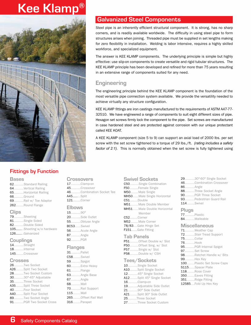
engineeringthe engineering principle behind the Kee Klamp component is the foundation of the most versatile pipe connection system available. we provide the versatility needed to achieve virtually any structure configuration.
Kee Klamp fittings are iron castings manufactured to the requirements of astm a47-77-32510. we have engineered a range of components to suit eight different sizes of pipe. hexagon set screws firmly lock the component to the pipe. set screws are manufactured in case hardened steel and are protected against corrosion with our unique protectant called Kee Koat.
a Kee Klamp component (size 5 to 9) can support an axial load of 2000 lbs. per set screw with the set screw tightened to a torque of 29 lbs./ft. (rating includes a safety factor of 2:1). this is normally obtained when the set screw is fully tightened using
Galvanized Steel Componentssteel pipe is an inherently efficient structural component. it is strong, has no sharp corners, and is readily available worldwide. the difficulty in using steel pipe to form structures arises when joining. threaded pipe must be supplied in set lengths making for zero flexibility in installation. welding is labor intensive, requires a highly skilled workforce, and specialized equipment.
the answer is Kee Klamp components. the underlying principle is simple but highly effective: use slip-on components to create versatile and rigid tubular structures. the Kee Klamp principle has been developed and refined for more than 75 years resulting in an extensive range of components suited for any need.
Bases62..........standard railing64..........vertical railing65..........horizontal railing66..........ground69..........rail w/ toe adaptor262........round flange
Clips79..........sheeting81..........single sided82..........double sided105........sheeting w/o hardware126........galvanized
Couplings14..........straight18..........internal145........crossover
Crosses26..........two socketa26........split two socket 28..........two socket custom30..........30°-45° adjustable35..........three socketa35........split three socket40..........four socketa40........split four socket89..........two socket angle91..........pgr two socket cross
Crossovers17..........clamp-on45..........crossover46..........combination socket teea45........split121........corner
elbows15..........90°20..........side outlet55..........obtuse angleBc53......swivel56..........acute angle87..........angle92..........pgr
Flanges31..........palletc58........swivel59..........spigot60..........extra heavy61..........flange63..........angle Base67..........angle68..........wall70..........rail support115........wall265........offset rail wall316........parapet
Swivel Socketsc50.........single combinationf50.........female singlem50........male singlemh50......male single horizontalc51........doublem51........male double membermh51......male double horizontal memberc52........cornerm52........male corner78/83....gate hinge setf151......gate fitting
Tab panelsp51.........offset double w/ slotp50.........offset sing. w/ slotp57.........single w/ slotp58.........double w/ csh
Tees/Sockets10..........single socketa10........split single socket12..........45° single socketa12........split 45° single socket16..........clamp-on19..........adjustable side outlet21..........90° side outleta21........split 90° side outlet25.........three socket27..........three socket custom
29..........30°-60° single socket46..........combination crossover86..........angle88..........three socket angle90..........pgr three socket93..........pedestrian guard rail114........swivel
plugs77..........plastic84..........malleable
miscellaneous71..........weather cap72..........stair tread support75..........collar76..........hook95..........pgr internal spigot97..........set screw98..........ratchet handle w/ Bits99..........hex Key100........plastic set screw capss115......spacer plate118........rose cover350........eaves fitting351........ridge fitting12585....fold up hex Key
Fittings by Function
6 Safety Components Catalog
www.keesafety.com 7
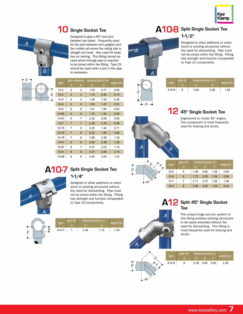
typepipe ref. measurements (in.)
weight (lb.)a D e f
12-5 5 1.46 2.83 1.38 0.66
12-6 6 1.73 3.35 1.38 0.95
12-7 7 2.17 3.70 1.58 1.56
12-8 8 2.36 4.25 1.58 2.02
e fD
45°
aa
12 45° Single Socket Tee engineered to create 45° angles. this component is most frequently used for bracing and struts.
typepipe ref. measurements (in.)
weight (lb.)a D e f
A12-8 8 2.36 4.80 2.05 2.36
a
a
D
e
f
45°
a12 Split 45° Single Socket Tee the unique hinge and pin system of this fitting enables existing structures to be easily extended without the need for dismantling. this fitting is most frequently used for bracing and struts.
10
typepipe reference measurements (in.)
weight (lb.)a B D e
10-2 2 2 1.00 0.77 0.04
10-3 3 3 1.13 0.94 0.15
10-4 4 4 1.36 1.20 0.29
10-5 5 5 1.63 1.47 0.51
10-6 6 6 1.81 1.84 0.64
10-65 6 5 1.75 1.42 0.55
10-67 6 7 2.20 2.06 0.95
10-7 7 7 2.38 2.16 0.99
10-75 7 5 2.25 1.44 0.71
10-76 7 6 2.25 1.80 0.95
10-78 7 8 2.88 2.38 1.39
10-8 8 8 2.69 2.38 1.28
10-87 8 7 2.47 2.03 1.10
10-9 9 9 3.31 2.88 2.14
10-98 9 8 2.94 2.50 1.43
Single Socket Tee designed to give a 90° butt joint between two pipes. frequently used for the joint between end uprights and the middle rail where the railing site is straight and level. also used for base ties on racking. this fitting cannot be used where through pipe is required to be joined within the fitting. type 25 should be used when a join in the pipe is necessary.
a
e
D
B
typepipe ref. measurements (in.)
weight (lb.)a D e
A10-7 7 2.36 1.10 1.26D
e
a
a
a10-7 Split Single Socket Tee
1-1/4"designed to allow additions or exten-sions to existing structures without the need for dismantling. pipe must not be joined within the fitting. fitting has strength and function comparable to type 10 components.
typepipe ref. measurements (in.)
weight (lb.)a D e
A10-8 8 3.46 2.36 1.59D
e
a
a
a10-8 Split Single Socket Tee
1-1/2"designed to allow additions or exten-sions to existing structures without the need for dismantling. pipe must not be joined within the fitting. fitting has strength and function comparable to type 10 components.
a
a
8 Safety Components Catalog
15
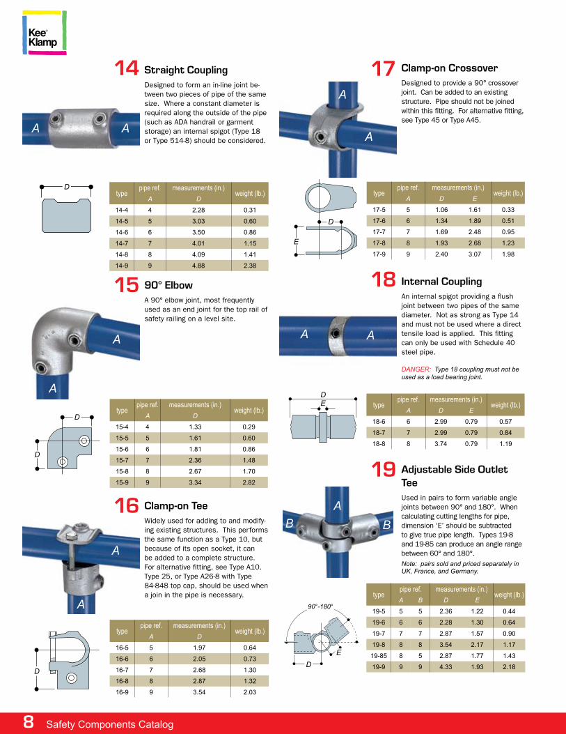
typepipe ref. measurements (in.)
weight (lb.)a D
15-4 4 1.33 0.29
15-5 5 1.61 0.60
15-6 6 1.81 0.86
15-7 7 2.36 1.48
15-8 8 2.67 1.70
15-9 9 3.34 2.82
90° elbowa 90° elbow joint, most frequently used as an end joint for the top rail of safety railing on a level site.
a
D
D
a
16
typepipe ref. measurements (in.)
weight (lb.)a D
16-5 5 1.97 0.64
16-6 6 2.05 0.73
16-7 7 2.68 1.30
16-8 8 2.87 1.32
16-9 9 3.54 2.03
Clamp-on Teewidely used for adding to and modify-ing existing structures. this performs the same function as a type 10, but because of its open socket, it can be added to a complete structure. for alternative fitting, see type a10. type 25, or type a26-8 with type 84-848 top cap, should be used when a join in the pipe is necessary.
a
a
D
17
typepipe ref. measurements (in.)
weight (lb.)a D e
17-5 5 1.06 1.61 0.33
17-6 6 1.34 1.89 0.51
17-7 7 1.69 2.48 0.95
17-8 8 1.93 2.68 1.23
17-9 9 2.40 3.07 1.98
Clamp-on Crossoverdesigned to provide a 90° crossover joint. can be added to an existing structure. pipe should not be joined within this fitting. for alternative fitting, see type 45 or type a45.
a
a
D
e
typepipe ref. measurements (in.)
weight (lb.)a B D e
19-5 5 5 2.36 1.22 0.44
19-6 6 6 2.28 1.30 0.64
19-7 7 7 2.87 1.57 0.90
19-8 8 8 3.54 2.17 1.17
19-85 8 5 2.87 1.77 1.43
19-9 9 9 4.33 1.93 2.18
19 adjustable Side outlet Tee used in pairs to form variable angle joints between 90° and 180°. when calculating cutting lengths for pipe, dimension ‘e’ should be subtracted to give true pipe length. types 19-8 and 19-85 can produce an angle range between 60° and 180°.Note: pairs sold and priced separately in UK, france, and Germany.
aBB
De
90°-180°
a
typepipe ref. measurements (in.)
weight (lb.)a D
14-4 4 2.28 0.31
14-5 5 3.03 0.60
14-6 6 3.50 0.86
14-7 7 4.01 1.15
14-8 8 4.09 1.41
14-9 9 4.88 2.38
14 Straight Coupling designed to form an in-line joint be-tween two pieces of pipe of the same size. where a constant diameter is required along the outside of the pipe (such as ada handrail or garment storage) an internal spigot (type 18 or type 514-8) should be considered.
D
a
e
18 Internal Couplingan internal spigot providing a flush joint between two pipes of the same diameter. not as strong as type 14 and must not be used where a direct tensile load is applied. this fitting can only be used with schedule 40 steel pipe.
DaNGeR: type 18 coupling must not be used as a load bearing joint.
a
Dtype
pipe ref. measurements (in.)weight (lb.)
a D e
18-6 6 2.99 0.79 0.57
18-7 7 2.99 0.79 0.84
18-8 8 3.74 0.79 1.19
a
www.keesafety.com 9
21
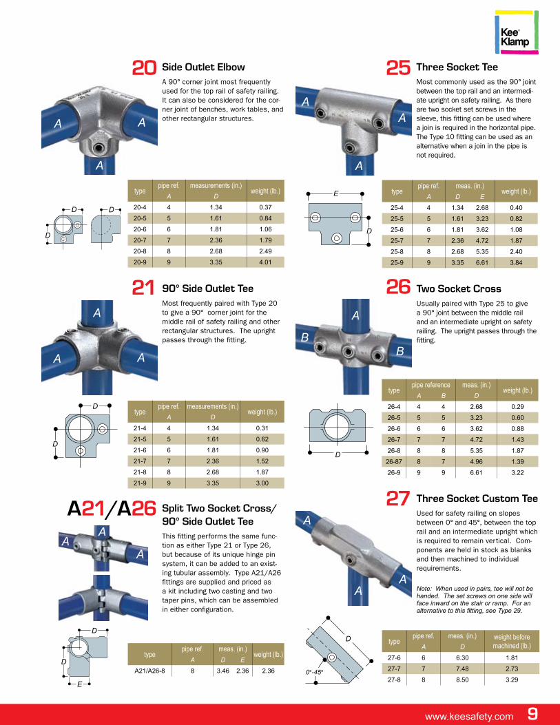
typepipe ref. measurements (in.)
weight (lb.)a D
21-4 4 1.34 0.31
21-5 5 1.61 0.62
21-6 6 1.81 0.90
21-7 7 2.36 1.52
21-8 8 2.68 1.87
21-9 9 3.35 3.00
90° Side outlet Teemost frequently paired with type 20 to give a 90° corner joint for the middle rail of safety railing and other rectangular structures. the upright passes through the fitting.
D
a
D
aa
20
typepipe ref. measurements (in.)
weight (lb.)a D
20-4 4 1.34 0.37
20-5 5 1.61 0.84
20-6 6 1.81 1.06
20-7 7 2.36 1.79
20-8 8 2.68 2.49
20-9 9 3.35 4.01
Side outlet elbowa 90° corner joint most frequently used for the top rail of safety railing. it can also be considered for the cor-ner joint of benches, work tables, and other rectangular structures.a
a
D D
D
a
25
typepipe ref. meas. (in.)
weight (lb.)a D e
25-4 4 1.34 2.68 0.40
25-5 5 1.61 3.23 0.82
25-6 6 1.81 3.62 1.08
25-7 7 2.36 4.72 1.87
25-8 8 2.68 5.35 2.40
25-9 9 3.35 6.61 3.84
Three Socket Teemost commonly used as the 90° joint between the top rail and an intermedi-ate upright on safety railing. as there are two socket set screws in the sleeve, this fitting can be used where a join is required in the horizontal pipe. the type 10 fitting can be used as an alternative when a join in the pipe is not required.
a
e
D
a
a
a
26 Two Socket Crossusually paired with type 25 to give a 90° joint between the middle rail and an intermediate upright on safety railing. the upright passes through the fitting.
typepipe reference meas. (in.)
weight (lb.)a B D
26-4 4 4 2.68 0.29
26-5 5 5 3.23 0.60
26-6 6 6 3.62 0.88
26-7 7 7 4.72 1.43
26-8 8 8 5.35 1.87
26-87 8 7 4.96 1.39
26-9 9 9 6.61 3.22
BB
D
27
typepipe ref. meas. (in.) weight before
machined (lb.)a D
27-6 6 6.30 1.81
27-7 7 7.48 2.73
27-8 8 8.50 3.29
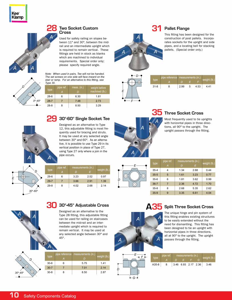
Three Socket Custom Teeused for safety railing on slopes between 0° and 45°, between the top rail and an intermediate upright which is required to remain vertical. com-ponents are held in stock as blanks and then machined to individual requirements.
Note: When used in pairs, tee will not be handed. the set screws on one side will face inward on the stair or ramp. for an alternative to this fitting, see Type 29.
a
D
0°-45°
aa
a21/a26
typepipe ref. meas. (in.)
weight (lb.)a D e
A21/A26-8 8 3.46 2.36 2.36
Split Two Socket Cross/ 90° Side outlet Teethis fitting performs the same func-tion as either type 21 or type 26, but because of its unique hinge pin system, it can be added to an exist-ing tubular assembly. type a21/a26 fittings are supplied and priced as a kit including two casting and two taper pins, which can be assembled in either configuration.
D
D
e
aa
a
10 Safety Components Catalog
a
35 Three Socket Crossmost frequently used to tie uprights with horizontal pipes in three direc-tions, all 90° to the upright. the upright passes through the fitting.
a
typepipe ref. measurements (in.)
weight (lb.)a D e
35-4 4 1.34 2.68 0.44
35-5 5 1.61 3.23 0.77
35-6 6 1.81 3.62 0.99
36-7 7 2.36 4.72 1.70
35-8 8 2.68 5.35 2.62
35-9 9 3.35 6.61 4.04
e
D
a
a
30
typepipe reference measurements (in.)
weight (lb.)a D
30-6 6 5.75 1.41
30-7 7 7.01 2.14
30-8 8 8.50 2.87
30°-45° adjustable Crossdesigned as an alternative to the type 28 fitting, this adjustable fitting can be used for railing on staircases between the mid-rail and an inter-mediate upright which is required to remain vertical. it may be used at any selected angle between 30° and 45°.
a
D
30°-45°
a
a
a35
typepipe ref. measurements (in.)
weight (lb.)a D e f G
A35-8 8 3.46 6.93 2.17 2.36 3.46
Split Three Socket Crossthe unique hinge and pin system of this fitting enables existing structures to be easily extended without the need for dismantling. this fitting has been designed to tie an upright with horizontal pipes in three directions, all at 90° to the upright. the upright passes through the fitting.
a
f
a a
a
e
G
D
29
typepipe ref. measurements (in.)
weight (lb.)a D e
29-6 6 3.23 2.52 0.97
29-7 7 3.66 2.91 1.39
29-8 8 4.02 2.68 2.14
30°-60° Single Socket Teedesigned as an alternative to type 12, this adjustable fitting is most fre-quently used for bracing and struts. it may be used at any selected angle between 30° and 60°. as an alterna-tive, it is possible to use type 29 in its vertical position in place of type 27, using type 27 only where a join in the pipe occurs.
D
e
30°-60°
a a
31
typepipe reference measurements (in.)
weight (lb.)a D e f
31-8 8 2.99 5 4.53 4.41
pallet Flangethis fitting has been designed for the construction of post pallets. incorpo-rates sockets for the upright and side pipes, and a locating bell for stacking pallets. (special order only.)
a
D
aa
e
f
28 Two Socket Custom Crossused for safety railing on slopes be-tween 11° and 30°, between the mid-rail and an intermediate upright which is required to remain vertical. these fittings are held in stock as blanks which are machined to individual requirements. special order only; please specify required angle.
a
typepipe ref. meas. (in.) weight before
machined (lb.)a D
28-6 6 6.30 1.81
28-7 7 7.48 2.73
28-8 8 8.50 3.29
Note: When used in pairs, tee will not be handed. the set screws on one side will face inward on the stair or ramp. For an alternative to this fitting, see type 30.
a a
D
0°-45°
www.keesafety.com 11
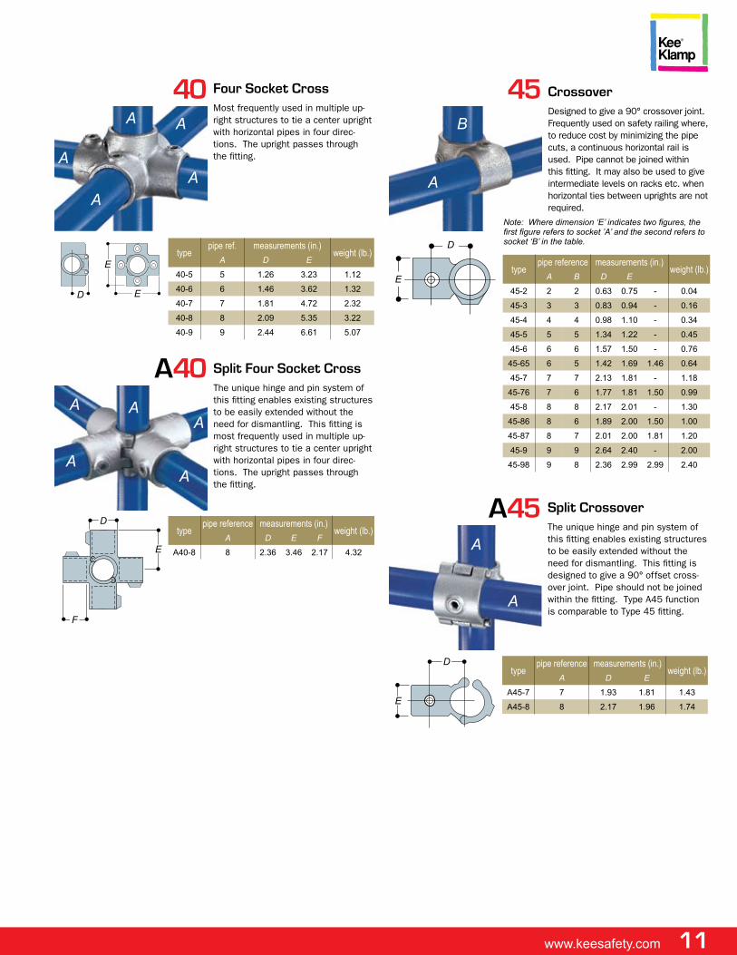
40
typepipe ref. measurements (in.)
weight (lb.)a D e
40-5 5 1.26 3.23 1.12
40-6 6 1.46 3.62 1.32
40-7 7 1.81 4.72 2.32
40-8 8 2.09 5.35 3.22
40-9 9 2.44 6.61 5.07
Four Socket Crossmost frequently used in multiple up-right structures to tie a center upright with horizontal pipes in four direc-tions. the upright passes through the fitting.
D
a
e
e
a
aa
a
a40
typepipe reference measurements (in.)
weight (lb.)a D e f
A40-8 8 2.36 3.46 2.17 4.32
Split Four Socket Crossthe unique hinge and pin system of this fitting enables existing structures to be easily extended without the need for dismantling. this fitting is most frequently used in multiple up-right structures to tie a center upright with horizontal pipes in four direc-tions. the upright passes through the fitting.
D
aa
aa
a
e
f
45
typepipe reference measurements (in.)
weight (lb.)a B D e
45-2 2 2 0.63 0.75 - 0.04
45-3 3 3 0.83 0.94 - 0.16
45-4 4 4 0.98 1.10 - 0.34
45-5 5 5 1.34 1.22 - 0.45
45-6 6 6 1.57 1.50 - 0.76
45-65 6 5 1.42 1.69 1.46 0.64
45-7 7 7 2.13 1.81 - 1.18
45-76 7 6 1.77 1.81 1.50 0.99
45-8 8 8 2.17 2.01 - 1.30
45-86 8 6 1.89 2.00 1.50 1.00
45-87 8 7 2.01 2.00 1.81 1.20
45-9 9 9 2.64 2.40 - 2.00
45-98 9 8 2.36 2.99 2.99 2.40
Crossover designed to give a 90° crossover joint. frequently used on safety railing where, to reduce cost by minimizing the pipe cuts, a continuous horizontal rail is used. pipe cannot be joined within this fitting. it may also be used to give intermediate levels on racks etc. when horizontal ties between uprights are not required.
a
D
Note: Where dimension ‘E’ indicates two figures, the first figure refers to socket ’A’ and the second refers to socket ‘B’ in the table.
e
B
a45
typepipe reference measurements (in.)
weight (lb.)a D e
A45-7 7 1.93 1.81 1.43
A45-8 8 2.17 1.96 1.74
Split Crossoverthe unique hinge and pin system of this fitting enables existing structures to be easily extended without the need for dismantling. this fitting is designed to give a 90° offset cross-over joint. pipe should not be joined within the fitting. type a45 function is comparable to type 45 fitting.
D
a
a
e
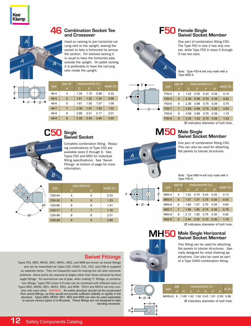
Swivel Fittingstypes f50, m50, mh50, m51, mh51, m52, and m58 are known as swivel fittings
and can be assembled as types c50, ch50, c51, c52, and c58 or supplied as separate items. they are frequently used for bracing but can also overcome
problems where joints are required at angles other than those achieved by fixed angle fittings. for economical use of pipe, when making 'c' fittings, or combina-
tion fittings, types f50 (sizes 5-9 only) can be combined with different sizes of types m50, mh50, m51, mh51, m52, and m58. f50-4 and m50-4 will only com-
bine with each other. warning: an entire structure should not be constructed from swivel fittings, as they would not provide sufficient stability or rigidity in the structure. types M50, MH50, M51, M52 and M58 can also be used separately to secure various types of in-fill panel. These fittings are not designed to take
bending moments.
12 Safety Components Catalog
m50 male SingleSwivel Socket memberone part of combination fitting c50. this can also be used for attaching flat panels to tubular structures.
Note: type M50-4 will only mate with a type f50-4.
a
e
typepipe ref. measurements (in.)
weight (lb.)a D e f Ø
M50-4 4 1.02 0.79 0.43 0.25 0.13
M50-5 5 1.57 1.57 0.75 0.39 0.53
M50-6 6 1.69 1.57 0.75 0.39 0.60
M50-7 7 1.89 1.85 0.75 0.39 0.79
M50-8 8 2.13 1.85 0.75 0.39 0.92
M50-9 9 2.44 2.05 0.75 0.39 1.19
D
f
Ø indicates diameter of bolt hole.
mH50
typepipe measurements (in.)
wt (lb.)a D e f G H Ø
MH50-6 6 1.69 1.42 1.50 0.43 1.81 0.39 0.66
male Single HorizontalSwivel Socket memberthis fitting can be used for attaching flat panels to tubular structures. spe-cially designed for retail shelving ap-plications. can also be used as part of a type ch50 combination fitting.
a
f
D
H
eG
Ø indicates diameter of bolt hole.
f
F50
typepipe ref measurements (in.)
weight (lb.)a D e f Ø
F50-4 4 1.42 0.55 0.43 0.26 0.15
F50-5 5 2.36 0.98 0.75 0.39 0.62
F50-6 6 2.36 0.98 0.75 0.39 0.75
F50-7 7 2.68 0.98 0.75 0.39 0.93
F50-8 8 2.99 0.98 0.75 0.39 1.15
F50-9 9 3.35 1.02 0.75 0.39 1.43
Female SingleSwivel Socket memberone part of combination fitting c50. the type f50 in size 4 has only one ear, while type f50 in sizes 5 through 9 has two ears.
Note: type f50-4 will only mate with a type M50-4.
e
a
D
Ø indicates diameter of bolt hole.
46 Combination Socket Teeand Crossoverused on racking to join horizontal car-rying rails to the upright, leaving the socket to take a horizontal tie across the section. for shelved racking it is usual to have the horizontal pipe outside the upright. on pallet racking it is preferable to have the carrying rails inside the upright.
a
e
typepipe ref. measurements (in.)
weight (lb.)a D e f
46-4 4 1.34 1.10 0.98 0.33
46-5 5 1.61 1.22 1.34 0.66
46-6 6 1.81 1.50 1.57 1.08
46-7 7 2.36 1.81 1.93 1.52
46-8 8 2.68 2.01 2.17 2.01
46-9 9 3.35 2.40 2.64 3.40
a a
f D
C50 SingleSwivel Socket complete combination fitting. reduc-ing combinations of type c50 are available sizes 5 through 9. see types f50 and m50 for individual fitting specifications. see ‘swivel fittings’ at bottom of page for more information.
a
85°
typepipe reference
weight (lb.)a B
C50-44 4 4 0.33
C50-55 5 5 1.23
C50-66 6 6 1.41
C50-77 7 7 1.76
C50-88 8 8 2.01
C50-99 9 9 2.69
B
85°
www.keesafety.com 13
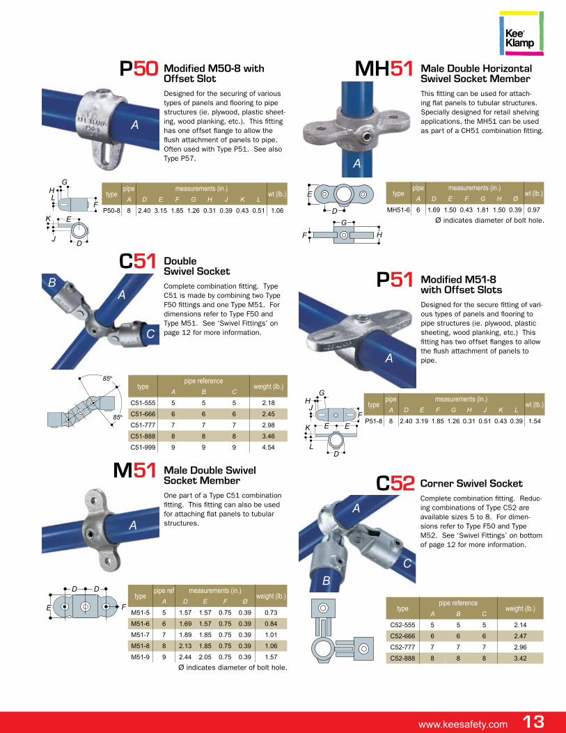
p50 modified m50-8 with offset Slotdesigned for the securing of various types of panels and flooring to pipe structures (ie. plywood, plastic sheet-ing, wood planking, etc.). this fitting has one offset flange to allow the flush attachment of panels to pipe. often used with type p51. see also type p57.
a
Gtype
pipe measurements (in.)wt (lb.)
a D e f G H J K L
P50-8 8 2.40 3.15 1.85 1.26 0.31 0.39 0.43 0.51 1.06f
D
e
J
K
LH
p51 modified m51-8with offset Slotsdesigned for the secure fitting of vari-ous types of panels and flooring to pipe structures (ie. plywood, plastic sheeting, wood planking, etc.) this fitting has two offset flanges to allow the flush attachment of panels to pipe.
f
a
typepipe measurements (in.)
wt (lb.)a D e f G H J K L
P51-8 8 2.40 3.19 1.85 1.26 0.31 0.51 0.43 0.39 1.54ee
DL
GHJ
K
C51 DoubleSwivel Socketcomplete combination fitting. type c51 is made by combining two type f50 fittings and one type m51. for dimensions refer to type f50 and type m51. see ‘swivel fittings’ on page 12 for more information.
B
typepipe reference
weight (lb.)a B C
C51-555 5 5 5 2.18
C51-666 6 6 6 2.45
C51-777 7 7 7 2.98
C51-888 8 8 8 3.46
C51-999 9 9 9 4.54
C
a
85°
85°
C52
typepipe reference
weight (lb.)a B C
C52-555 5 5 5 2.14
C52-666 6 6 6 2.47
C52-777 7 7 7 2.96
C52-888 8 8 8 3.42
Corner Swivel Socketcomplete combination fitting. reduc-ing combinations of type c52 are available sizes 5 to 8. for dimen-sions refer to type f50 and type m52. see ‘swivel fittings’ on bottom of page 12 for more information.
a
CB
m51 male Double Swivel Socket memberone part of a type c51 combination fitting. this fitting can also be used for attaching flat panels to tubular structures.a
Dtype
pipe ref measurements (in.)weight (lb.)
a D e f Ø
M51-5 5 1.57 1.57 0.75 0.39 0.73
M51-6 6 1.69 1.57 0.75 0.39 0.84
M51-7 7 1.89 1.85 0.75 0.39 1.01
M51-8 8 2.13 1.85 0.75 0.39 1.06
M51-9 9 2.44 2.05 0.75 0.39 1.57
D
e f
Ø indicates diameter of bolt hole.
mH51 male Double HorizontalSwivel Socket memberthis fitting can be used for attach-ing flat panels to tubular structures. specially designed for retail shelving applications, the mh51 can be used as part of a ch51 combination fitting.
a
D
typepipe measurements (in.)
wt (lb.)a D e f G H Ø
MH51-6 6 1.69 1.50 0.43 1.81 1.50 0.39 0.97
e
GHf
Ø indicates diameter of bolt hole.
14 Safety Components Catalog
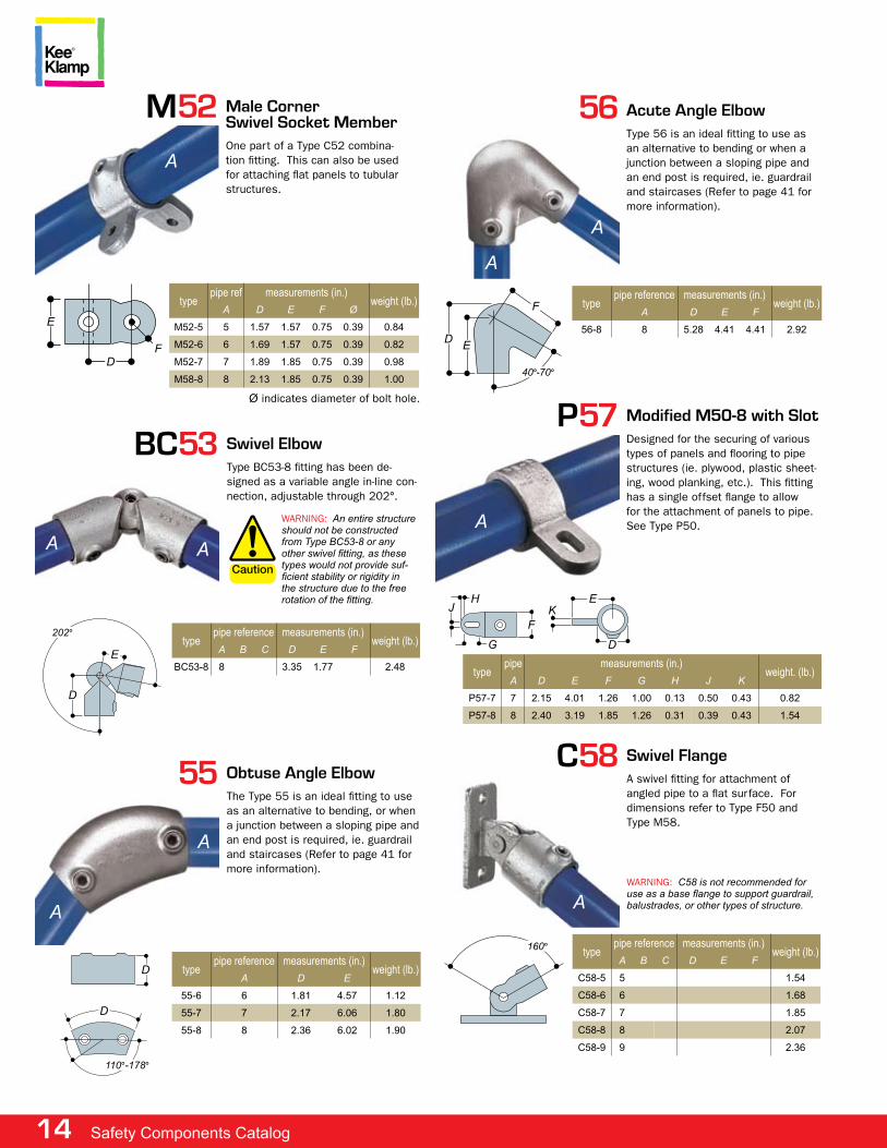
a
56 acute angle elbowtype 56 is an ideal fitting to use as an alternative to bending or when a junction between a sloping pipe and an end post is required, ie. guardrail and staircases (refer to page 41 for more information).
f typepipe reference measurements (in.)
weight (lb.)a D e f
56-8 8 5.28 4.41 4.41 2.92
a
eD
40°-70°
C58
typepipe reference measurements (in.)
weight (lb.)a B C D e f
C58-5 5 1.54
C58-6 6 1.68
C58-7 7 1.85
C58-8 8 2.07
C58-9 9 2.36
Swivel Flangea swivel fitting for attachment of angled pipe to a flat surface. for dimensions refer to type f50 and type m58.
warning: C58 is not recommended for use as a base flange to support guardrail, balustrades, or other types of structure.a
160°
m52
typepipe ref measurements (in.)
weight (lb.)a D e f Ø
M52-5 5 1.57 1.57 0.75 0.39 0.84
M52-6 6 1.69 1.57 0.75 0.39 0.82
M52-7 7 1.89 1.85 0.75 0.39 0.98
M58-8 8 2.13 1.85 0.75 0.39 1.00
male CornerSwivel Socket memberone part of a type c52 combina-tion fitting. this can also be used for attaching flat panels to tubular structures.
a
e
Df
Ø indicates diameter of bolt hole.
BC53
typepipe reference measurements (in.)
weight (lb.)a B C D e f
BC53-8 8 3.35 1.77 2.48
Swivel elbowtype Bc53-8 fitting has been de-signed as a variable angle in-line con-nection, adjustable through 202°.
a a
202°
e
D
warning: an entire structure should not be constructed from type BC53-8 or any other swivel fitting, as these types would not provide suf-ficient stability or rigidity in the structure due to the free rotation of the fitting.
55
typepipe reference measurements (in.)
weight (lb.)a D e
55-6 6 1.81 4.57 1.12
55-7 7 2.17 6.06 1.80
55-8 8 2.36 6.02 1.90
obtuse angle elbowthe type 55 is an ideal fitting to use as an alternative to bending, or when a junction between a sloping pipe and an end post is required, ie. guardrail and staircases (refer to page 41 for more information).
a
D
a
D
110°-178°
p57 modified m50-8 with Slotdesigned for the securing of various types of panels and flooring to pipe structures (ie. plywood, plastic sheet-ing, wood planking, etc.). this fitting has a single offset flange to allow for the attachment of panels to pipe. see type p50.a
typepipe measurements (in.)
weight. (lb.)a D e f G H J K
P57-7 7 2.15 4.01 1.26 1.00 0.13 0.50 0.43 0.82
P57-8 8 2.40 3.19 1.85 1.26 0.31 0.39 0.43 1.54
f
HJ
G
eK
D
www.keesafety.com 15
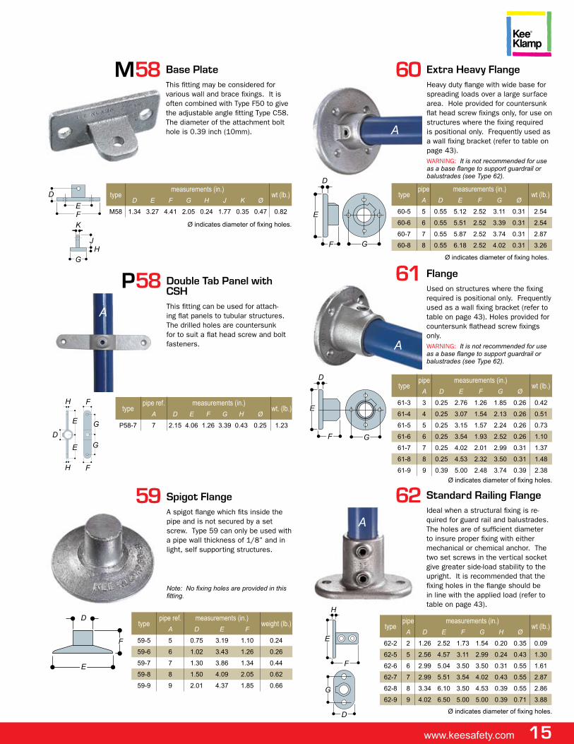
59
typepipe ref. measurements (in.)
weight (lb.)a D e f
59-5 5 0.75 3.19 1.10 0.24
59-6 6 1.02 3.43 1.26 0.26
59-7 7 1.30 3.86 1.34 0.44
59-8 8 1.50 4.09 2.05 0.62
59-9 9 2.01 4.37 1.85 0.66
Spigot Flangea spigot flange which fits inside the pipe and is not secured by a set screw. type 59 can only be used with a pipe wall thickness of 1/8” and in light, self supporting structures.
Note: No fixing holes are provided in this fitting.
e
f
D
61 Flangeused on structures where the fixing required is positional only. frequently used as a wall fixing bracket (refer to table on page 43). holes provided for countersunk flathead screw fixings only.warning: It is not recommended for use as a base flange to support guardrail or balustrades (see type 62).
a
Gf
D
e
typepipe measurements (in.)
wt (lb.)a D e f G Ø
61-3 3 0.25 2.76 1.26 1.85 0.26 0.42
61-4 4 0.25 3.07 1.54 2.13 0.26 0.51
61-5 5 0.25 3.15 1.57 2.24 0.26 0.73
61-6 6 0.25 3.54 1.93 2.52 0.26 1.10
61-7 7 0.25 4.02 2.01 2.99 0.31 1.37
61-8 8 0.25 4.53 2.32 3.50 0.31 1.48
61-9 9 0.39 5.00 2.48 3.74 0.39 2.38
Ø indicates diameter of fixing holes.
62
typepipe measurements (in.)
wt (lb.)a D e f G H Ø
62-2 2 1.26 2.52 1.73 1.54 0.20 0.35 0.09
62-5 5 2.56 4.57 3.11 2.99 0.24 0.43 1.30
62-6 6 2.99 5.04 3.50 3.50 0.31 0.55 1.61
62-7 7 2.99 5.51 3.54 4.02 0.43 0.55 2.87
62-8 8 3.34 6.10 3.50 4.53 0.39 0.55 2.86
62-9 9 4.02 6.50 5.00 5.00 0.39 0.71 3.88
Standard Railing Flangeideal when a structural fixing is re-quired for guard rail and balustrades. the holes are of sufficient diameter to insure proper fixing with either mechanical or chemical anchor. the two set screws in the vertical socket give greater side-load stability to the upright. it is recommended that the fixing holes in the flange should be in line with the applied load (refer to table on page 43).
a
D
G
f
e
H
Ø indicates diameter of fixing holes.
m58
typemeasurements (in.)
wt (lb.)D e f G H J K Ø
M58 1.34 3.27 4.41 2.05 0.24 1.77 0.35 0.47 0.82
Base platethis fitting may be considered for various wall and brace fixings. it is often combined with type f50 to give the adjustable angle fitting type c58. the diameter of the attachment bolt hole is 0.39 inch (10mm).
DefK
HJ
G
Ø indicates diameter of fixing holes.
p58 Double Tab panel with CSHthis fitting can be used for attach-ing flat panels to tubular structures. the drilled holes are countersunk for to suit a flat head screw and bolt fasteners.
typepipe ref. measurements (in.)
wt. (lb.)a D e f G H Ø
P58-7 7 2.15 4.06 1.26 3.39 0.43 0.25 1.23
fH
Ge
DGe
fH
a
60 extra Heavy Flangeheavy duty flange with wide base for spreading loads over a large surface area. hole provided for countersunk flat head screw fixings only, for use on structures where the fixing required is positional only. frequently used as a wall fixing bracket (refer to table on page 43).warning: It is not recommended for use as a base flange to support guardrail or balustrades (see type 62).
a
Gf
e
D
typepipe measurements (in.)
wt (lb.)a D e f G Ø
60-5 5 0.55 5.12 2.52 3.11 0.31 2.54
60-6 6 0.55 5.51 2.52 3.39 0.31 2.54
60-7 7 0.55 5.87 2.52 3.74 0.31 2.87
60-8 8 0.55 6.18 2.52 4.02 0.31 3.26
Ø indicates diameter of fixing holes.
16 Safety Components Catalog
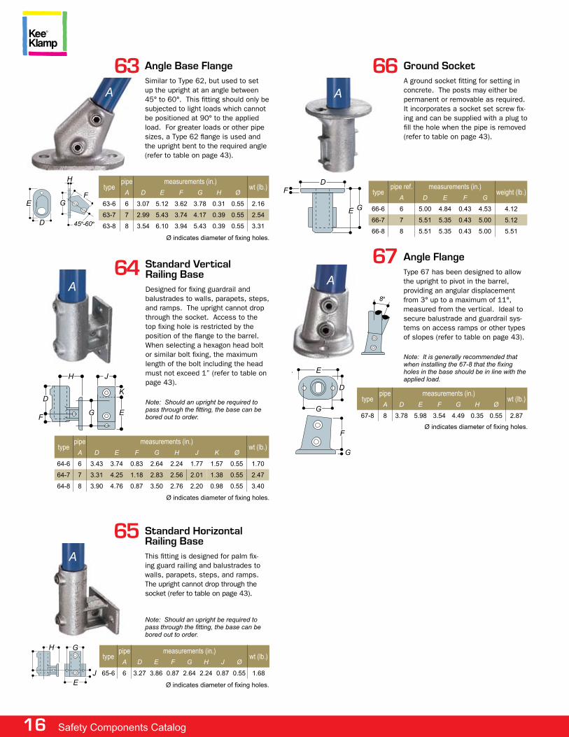
67 angle Flangetype 67 has been designed to allow the upright to pivot in the barrel, providing an angular displacement from 3° up to a maximum of 11°, measured from the vertical. ideal to secure balustrade and guardrail sys-tems on access ramps or other types of slopes (refer to table on page 43).
Note: It is generally recommended that when installing the 67-8 that the fixing holes in the base should be in line with the applied load.
a
Dtype
pipe measurements (in.)wt (lb.)
a D e f G H Ø
67-8 8 3.78 5.98 3.54 4.49 0.35 0.55 2.87
e
G
f
G
8°
Ø indicates diameter of fixing holes.
66
typepipe ref. measurements (in.)
weight (lb.)a D e f G
66-6 6 5.00 4.84 0.43 4.53 4.12
66-7 7 5.51 5.35 0.43 5.00 5.12
66-8 8 5.51 5.35 0.43 5.00 5.51
Ground Socketa ground socket fitting for setting in concrete. the posts may either be permanent or removable as required. it incorporates a socket set screw fix-ing and can be supplied with a plug to fill the hole when the pipe is removed (refer to table on page 43).
a
D
Ge
f
a64 Standard Vertical
Railing Basedesigned for fixing guardrail and balustrades to walls, parapets, steps, and ramps. the upright cannot drop through the socket. access to the top fixing hole is restricted by the position of the flange to the barrel. when selecting a hexagon head bolt or similar bolt fixing, the maximum length of the bolt including the head must not exceed 1” (refer to table on page 43).
Note: Should an upright be required to pass through the fitting, the base can be bored out to order.
H
typepipe measurements (in.)
wt (lb.)a D e f G H J K Ø
64-6 6 3.43 3.74 0.83 2.64 2.24 1.77 1.57 0.55 1.70
64-7 7 3.31 4.25 1.18 2.83 2.56 2.01 1.38 0.55 2.47
64-8 8 3.90 4.76 0.87 3.50 2.76 2.20 0.98 0.55 3.40
f
D
J
K
G e
Ø indicates diameter of fixing holes.
63 angle Base Flangesimilar to type 62, but used to set up the upright at an angle between 45° to 60°. this fitting should only be subjected to light loads which cannot be positioned at 90° to the applied load. for greater loads or other pipe sizes, a type 62 flange is used and the upright bent to the required angle (refer to table on page 43).
a
G
typepipe measurements (in.)
wt (lb.)a D e f G H Ø
63-6 6 3.07 5.12 3.62 3.78 0.31 0.55 2.16
63-7 7 2.99 5.43 3.74 4.17 0.39 0.55 2.54
63-8 8 3.54 6.10 3.94 5.43 0.39 0.55 3.31
f
H
e
D 45°-60°
Ø indicates diameter of fixing holes.
65 Standard HorizontalRailing Basethis fitting is designed for palm fix-ing guard railing and balustrades to walls, parapets, steps, and ramps. the upright cannot drop through the socket (refer to table on page 43).
Note: Should an upright be required to pass through the fitting, the base can be bored out to order.
a
e
typepipe measurements (in.)
wt (lb.)a D e f G H J Ø
65-6 6 3.27 3.86 0.87 2.64 2.24 0.87 0.55 1.68
GH
JØ indicates diameter of fixing holes.
www.keesafety.com 17
69
typepipe measurements (in.)
a D e f G H J K
69-6 6 5.12 2.95 3.07 3.74 2.28 0.59 0.39
69-7 7 5.71 3.15 3.54 3.82 2.28 0.79 0.39
69-8 8 6.30 3.54 3.54 4.41 2.28 0.79 0.39
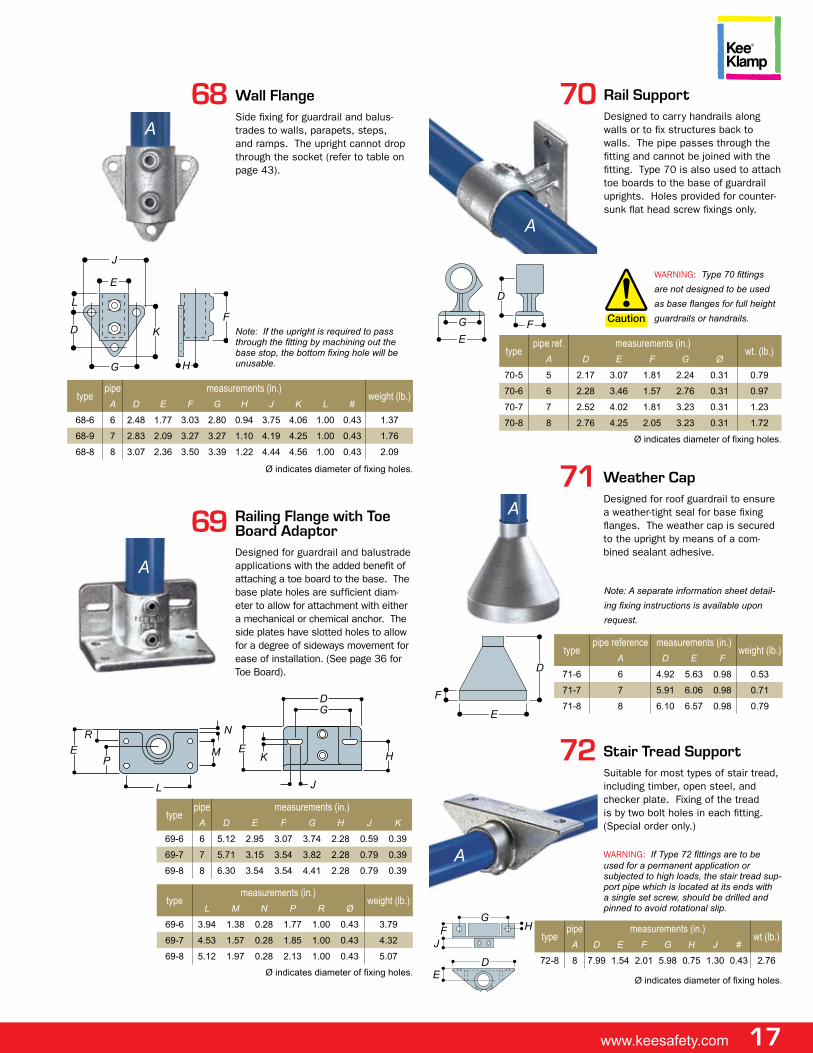
Railing Flange with Toe Board adaptordesigned for guardrail and balustrade applications with the added benefit of attaching a toe board to the base. the base plate holes are sufficient diam-eter to allow for attachment with either a mechanical or chemical anchor. the side plates have slotted holes to allow for a degree of sideways movement for ease of installation. (see page 36 for toe Board).
a
N
typemeasurements (in.)
weight (lb.)L M N P R Ø
69-6 3.94 1.38 0.28 1.77 1.00 0.43 3.79
69-7 4.53 1.57 0.28 1.85 1.00 0.43 4.32
69-8 5.12 1.97 0.28 2.13 1.00 0.43 5.07
M
L
Pe
Re
K
J
GD
H
Ø indicates diameter of fixing holes.
68 Wall Flangeside fixing for guardrail and balus-trades to walls, parapets, steps, and ramps. the upright cannot drop through the socket (refer to table on page 43).
Note: If the upright is required to pass through the fitting by machining out the base stop, the bottom fixing hole will be unusable.
a
f
typepipe measurements (in.)
weight (lb.)a D e f G H J K L #
68-6 6 2.48 1.77 3.03 2.80 0.94 3.75 4.06 1.00 0.43 1.37
68-9 7 2.83 2.09 3.27 3.27 1.10 4.19 4.25 1.00 0.43 1.76
68-8 8 3.07 2.36 3.50 3.39 1.22 4.44 4.56 1.00 0.43 2.09
H
K
G
e
J
D
L
Ø indicates diameter of fixing holes.
72 Stair Tread Supportsuitable for most types of stair tread, including timber, open steel, and checker plate. fixing of the tread is by two bolt holes in each fitting. (special order only.)
warning: If Type 72 fittings are to be used for a permanent application or subjected to high loads, the stair tread sup-port pipe which is located at its ends with a single set screw, should be drilled and pinned to avoid rotational slip.
a
G
typepipe measurements (in.)
wt (lb.)a D e f G H J #
72-8 8 7.99 1.54 2.01 5.98 0.75 1.30 0.43 2.76
f
De
HJ
Ø indicates diameter of fixing holes.
71
typepipe reference measurements (in.)
weight (lb.)a D e f
71-6 6 4.92 5.63 0.98 0.53
71-7 7 5.91 6.06 0.98 0.71
71-8 8 6.10 6.57 0.98 0.79
Weather Capdesigned for roof guardrail to ensure a weather-tight seal for base fixing flanges. the weather cap is secured to the upright by means of a com-bined sealant adhesive.
e
a
D
f
Note: a separate information sheet detail-ing fixing instructions is available upon request.
70 Rail Supportdesigned to carry handrails along walls or to fix structures back to walls. the pipe passes through the fitting and cannot be joined with the fitting. type 70 is also used to attach toe boards to the base of guardrail uprights. holes provided for counter-sunk flat head screw fixings only.
a
f
typepipe ref. measurements (in.)
wt. (lb.)a D e f G Ø
70-5 5 2.17 3.07 1.81 2.24 0.31 0.79
70-6 6 2.28 3.46 1.57 2.76 0.31 0.97
70-7 7 2.52 4.02 1.81 3.23 0.31 1.23
70-8 8 2.76 4.25 2.05 3.23 0.31 1.72
D
Ge
warning: Type 70 fittings are not designed to be used as base flanges for full height guardrails or handrails.
Ø indicates diameter of fixing holes.
18 Safety Components Catalog
79 Sheeting Clipthis fitting is used to attach profiled sheeting material to pipe. the fitting is supplied with the following hard-ware: one m6x50mm roofing bolt, on m6 square nut, and one m6 lock washer. BZp finish.
typepipe measurements (in.)
wt (lb.)a D e f G Ø
79-7 7 1.81 1.34 0.31 0.83 0.31 0.18
a
GD e
f
Ø indicates diameter of bolt hole.
81 Single Sided Clipfor attaching wire mesh in-fill. for economy it is possible to use type 81 clips without the safety attach-ment to secure various types of in-fill panels (ply-board, perspeX, etc. ) up to a thickness of 25/64”. all clips are supplied with hexagonal head fixing bolts, m6x35mm long and nut. the primary clip has a slot measuring 0.31 x 0.59 inches.
typepipe ref measurements (in.)
weight (lb.)a B D e f Ø
81-5 5 0.94 1.77 2.20 0.28 0.15
81-6 6 1.06 2.05 2.32 0.28 0.18
81-7 7 1.26 2.24 2.52 0.28 0.18
81-8 8 1.34 2.32 2.60 0.28 0.20
81-9 9 1.57 2.56 2.83 0.28 0.22
Note: For D and E dimensions the figures are given for the respective minimum and maximum dimensions allowed by the slotted hole.D
e
f
Ø indicates diameter of the safety attachment bolt hole.
78
typepipe reference measurements (in.)
weight (lb.)a D e Ø
78-5 5 1.18 1.02 0.46 0.46
78-6 6 1.30 1.02 0.55 0.55
78-7 7 1.50 1.02 0.57 0.57
78-8 8 1.61 1.02 0.62 0.62
eye Fittingused in conjunction with type 83 fit-ting for gate hinges.
a
D e
Ø indicates diameter of pivot hole.
75
typepipe reference measurements (in.)
weight (lb.)a D
75-4 4 0.91 0.11
75-5 5 1.02 0.29
75-6 6 1.02 0.29
75-7 7 1.02 0.33
75-8 8 1.02 0.42
Collarcommonly used to support another fitting if the latter is required to be left untightened, such as gate hinges. type 75 is also useful when the loading on a structure exceeds the maximum permitted slip load for a set screw, as it gives it additional support.
a
D
76
typepipe reference measurements (in.)
weight (lb.)a D e f
76-5 5 1.18 1.06 0.35 0.37
76-6 6 1.38 1.06 0.51 0.46
76-7 7 1.50 1.06 0.51 0.51
76-8 8 1.61 1.06 0.51 0.53
Hooka fitting normally used for attachment of chains.
a
e
D
f
77
typepipe reference
weight (lb.)a
77-4 4 0.002
77-5 5 0.009
77-6 6 0.015
77-7 7 0.035
77-8 8 0.044
77-9 9 0.05
plastic pluggrey plastic plug to fit open ended pipes. see also type 84.
Note: This fitting can be used with Sched-ule 40 or 80 pipe only
The Slope Range (86-89)the slope range of fittings consists of fitting types 86, 87, 88, 89. these fittings are designed to facilitate in-line railings with vertical posts on slopes with angles between 0 and 11. they can be used to construct railings on access ramps for people with disabilities when used in conjunction with the Kee lite type l160 fitting.
www.keesafety.com 19
typepipe reference
weight (lb.)a
84-5 5 0.11
84-6 6 0.22
84-7 7 0.26
84-8 8 0.37
84-9 9 0.64
84 malleable pluga metal drive-in plug which is difficult to remove when installed. for an alternative in plastic, see type 77.
Note: This fitting can only be used with Schedule 40 steel pipe.
86
typepipe ref. measurements (in.)
weight (lb.)a D
86-7 7 2.36 1.25
86-8 8 2.68 1.68
angle Teeused to join the middle rail to an up-right on a guardrail on a slope from 0° to 11°. pipe cannot be joined within this fitting.
D
a
a
11°
11°
87
typepipe reference measurements (in.)
weight (lb.)a D
87-7 7 2.36 1.80
87-8 8 2.68 1.98
angle elbowused to join the top rail to an end up-right on a guardrail on a slope from 0° to 11°. pipe cannot be joined within this fitting.
D
a
a
79°-101°
88
typepipe reference measurements (in.)
weight (lb.)a D e
88-7 7 2.36 5.67 2.16
88-8 8 2.68 6.22 2.73
Three Socket angle Teeused to join the top rail to an inter-mediate upright on a guardrail on a slope from 0° to 11°. as there are two socket set screws in the sleeve, this fitting can be used to join two ends of rail.
D
a
11°
aa
e
11°
82 Double Sided Clipfor attaching wire-mesh in-fill. for economy it is possible to use type 82 clips without the safety attach-ment, to secure various types of in-fill panels (ply-board, perspeX, etc.) up to a thickness of 25/64”. all clips are supplied with hexagonal head fixing bolts, m6x35mm long, and nut. the primary clip has a slot measuring 8mm x 15mm.
typepipe ref. measurements (in.)
weight (lb.)a D e f Ø
82-5 5 0.94 1.77 4.41 0.28 0.24
82-6 6 1.06 2.05 4.65 0.28 0.26
82-7 7 1.26 2.24 5.04 0.28 0.29
82-8 8 1.34 2.32 5.20 0.28 0.31
82-9 9 1.57 2.56 5.67 0.28 0.31
Note: For D and E dimensions the figures are given for the respective minimum and maximum dimensions allowed by the slotted hole.
D De e
f
Ø indicates diameter of the safety attachment bolt hole.
a
83 pin Fittingthis fitting is used in conjunction with type 78 for gate hinges.
typepipe ref. measurements (in.)
weight (lb.)a D e f Ø
83-5 5 1.18 1.02 1.50 0.51 0.44
83-6 6 1.30 1.02 1.50 0.51 0.55
83-7 7 1.50 1.02 1.50 0.51 0.64
83-8 8 1.61 1.02 1.50 0.51 0.66
Df
e
Ø
a
20 Safety Components Catalog
93 pGR Teetype 93 is used to join the mid-rail to an end post. (special order only).
e
a
a
D
typepipe refer- measurements (in.)
weight (lb.)a D e
93-8 8 3.90 3.54 2.65
95 pGR Internal Spigotinternal spigot designed to prevent sagging of bends when using the 90 to 95 range of fittings. (special order only).
typepipe reference
weight (lb.)a
95-8 8 1.01
92
typepipe reference measurements (in.)
weight (lb.)a D e
92-8 8 3.90 3.50 2.84
pGR elbowtype 92 is used to join the top rail to an end post. (special order only).
a
e
D
a
The pGR Range (90 to 95)these are known as pedestrian guardrail (pgr) fittings and are used as an
alternative to types 10, 15, 25, and 26 when the site is not straight and level.
there is sufficient play within the fitting to negotiate a slope up to 7 feet or a
radius greater than 20 feet, when the uprights are at 6-1/2 foot centers, using
straight pipe. they also allow damaged rails to be removed without dismantling
the adjacent structure. the 90 to 95 range of fittings is available in size 8.
special order only.
89
typepipe reference measurements (in.)
weight (lb.)a D
89-7 7 5.67 1.62
89-8 8 6.22 2.05
Two Socket angle Crossused to join the middle rail to an intermediate upright on a guardrail on a slope from 0 to 11. the upright passes through the fitting.
11°
a
D
11°
aa
90
typepipe reference measurements (in.)
weight (lb.)a B C D e f
90-8 8 3.90 3.46 3.90
pGR Three Socket Teetype 90 is used to join the top rail to an intermediate upright. (special order only).
e
a
a
D
91
typepipe reference measurements (in.)
weight (lb.)a D e
91-8 8 3.90 3.50 3.97
pGR Two Socket Crosstype 91 is used to join the mid-rail to an intermediate upright. (special order only).
a
e
D
a
a
www.keesafety.com 21
97
type to suit pipe sizes description
97-2 2 3 5/16” BSF
97-4 4 3/8” BSF
97-6 5 6 ISO 228 G1 1/4”
97-7 7 8 9 ISO 228 GI 3/8”
Set Screwssocket set screws are supplied in all Kee Klamp fittings as standard. Kee Koat, applied as standard throughout the Kee Klamp range, provides the set screws with up to four times the corrosion resistance of Bright Zinc plating.
100 plastic Set Screw Capgrey plastic set screw caps provide the perfect finishing touch to galva-nized Kee Klamp fittings. secure push-in-fit application.
e
D
typepipe reference measurements (in.)
weight (lb.)a B C D e f
93-8 8 3.90 3.54 2.65
114
typepipe ref. measurements (in.)
weight (lb.)a D e f
114-2 2 0.43 0.51 0.83 0.04
114-6 6 0.83 1.34 1.14 0.79
114-7 7 1.02 1.65 1.42 1.19
114-8 8 1.14 1.93 1.61 1.41
Swivel Teean internal swivel fitting, designed to accommodate varying angles on handrail for staircases, ramps, or bracing. used in conjunction with types 10, 15, 25, or 45. eliminates the need for specially drilled angle fitting type 27 and 28.
D
a
f
e
105 Sheeting Clip without Hardwarethis clip is used to attach profiled or flat sheeting. not supplied with hardware.
Note: For use where fixing required is positional only. Clip is not intended to bear substantial load.
D
a
typepipe measurements (in.)
wt (lb.)a D e f G Ø
105-6 6 1.26 1.57 0.51 1.97 0.35 0.31
105-7 7 1.50 1.57 0.51 1.97 0.35 0.35
105-8 8 1.57 1.57 0.51 1.97 0.35 0.40
105-9 9 1.89 1.57 0.51 1.97 0.35 0.51
e
f
G
Ø indicates diameter of bolt hole.
115 Wall Flangetype 115 is designed for palm fixing of guard rail and balustrades to walls, parapets, steps, and ramps. the upright cannot drop through the socket. packer plates, type s115, are available to allow the fitting to be positioned in channels, slots, and other offset areas.
e
a
typepipe measurements (in.)
wt (lb.)a D e f G H J Ø
115-6 6 5.91 3.94 1.18 3.54 2.56 0.39 0.55 2.34
115-7 7 5.91 3.94 1.38 3.54 2.56 0.39 0.55 2.71
115-8 8 5.91 3.94 1.61 3.54 2.56 0.39 0.55 3.13
D
G
f
H
J
Ø indicates diameter of fixing hole.
S115 packer plate for Type 115type s115 allows the type 115 fitting to be positioned in channels, slots, and other offset areas.
typemeasurements (in.)
wt. (lb.)D e f G Ø
S115 5.90 2.56 0.47 3.94 0.55 1.92
G
D
e
f
Ø indicates diameter of fixing hole.
22 Safety Components Catalog
262
typepipe ref. measurements (in.)
wt. (lb.)a D e f Ø
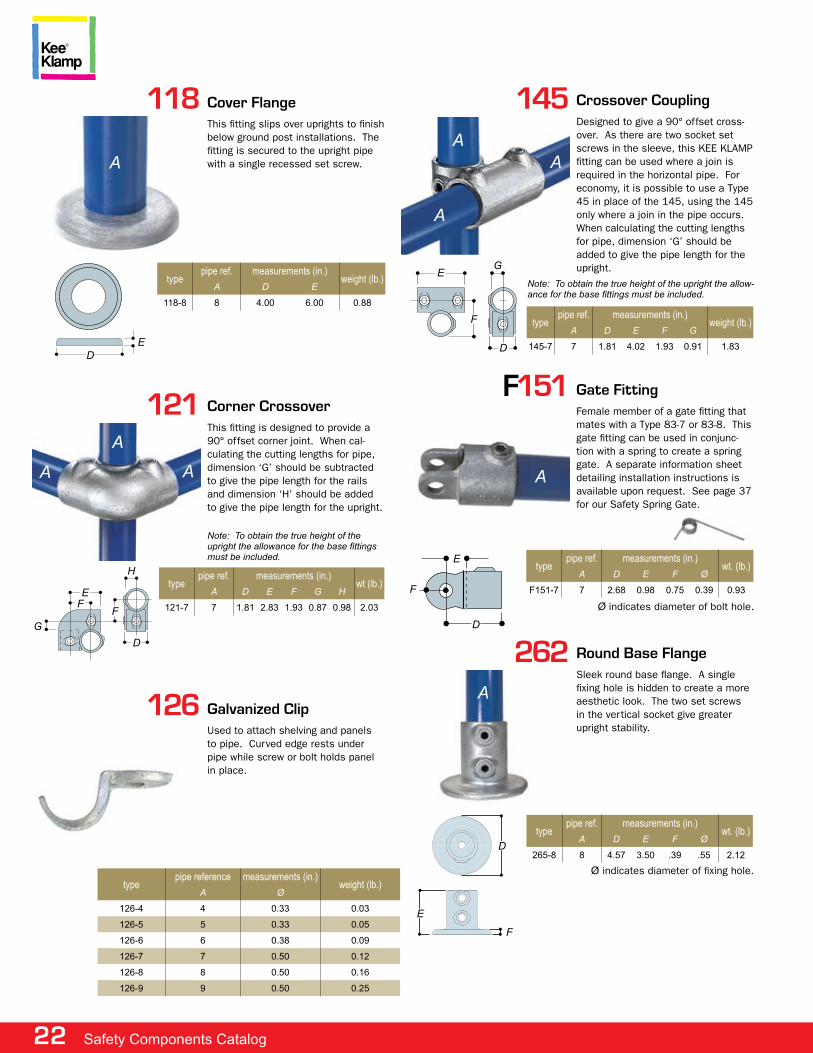
265-8 8 4.57 3.50 .39 .55 2.12
Round Base Flangesleek round base flange. a single fixing hole is hidden to create a more aesthetic look. the two set screws in the vertical socket give greater upright stability.
a
Ø indicates diameter of fixing hole.
D
e
f
145 Crossover Couplingdesigned to give a 90° offset cross-over. as there are two socket set screws in the sleeve, this Kee Klamp fitting can be used where a join is required in the horizontal pipe. for economy, it is possible to use a type 45 in place of the 145, using the 145 only where a join in the pipe occurs. when calculating the cutting lengths for pipe, dimension ‘g’ should be added to give the pipe length for the upright.
a
D
Note: to obtain the true height of the upright the allow-ance for the base fittings must be included.
a
a
typepipe ref. measurements (in.)
weight (lb.)a D e f G
145-7 7 1.81 4.02 1.93 0.91 1.83
f
eG
126 Galvanized Clipused to attach shelving and panels to pipe. curved edge rests under pipe while screw or bolt holds panel in place.
121
typepipe ref. measurements (in.)
wt (lb.)a D e f G H
121-7 7 1.81 2.83 1.93 0.87 0.98 2.03
Corner Crossoverthis fitting is designed to provide a 90° offset corner joint. when cal-culating the cutting lengths for pipe, dimension ‘g’ should be subtracted to give the pipe length for the rails and dimension ‘h’ should be added to give the pipe length for the upright.
Note: to obtain the true height of the upright the allowance for the base fittings must be included.
a
D
aa
ffe
H
G
118 Cover Flangethis fitting slips over uprights to finish below ground post installations. the fitting is secured to the upright pipe with a single recessed set screw.a
typepipe ref. measurements (in.)
weight (lb.)a D e
118-8 8 4.00 6.00 0.88
De
typepipe reference measurements (in.)
weight (lb.)a Ø
126-4 4 0.33 0.03
126-5 5 0.33 0.05
126-6 6 0.38 0.09
126-7 7 0.50 0.12
126-8 8 0.50 0.16
126-9 9 0.50 0.25
F151 Gate Fittingfemale member of a gate fitting that mates with a type 83-7 or 83-8. this gate fitting can be used in conjunc-tion with a spring to create a spring gate. a separate information sheet detailing installation instructions is available upon request. see page 37 for our safety spring gate.
a
typepipe ref. measurements (in.)
wt. (lb.)a D e f Ø
F151-7 7 2.68 0.98 0.75 0.39 0.93
D
e
fØ indicates diameter of bolt hole.
www.keesafety.com 23
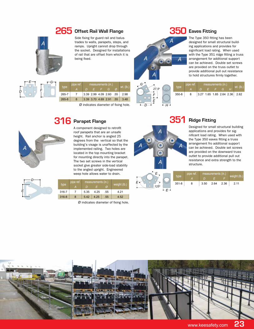
350
typepipe ref. measurements (in.)
wt. (lb.)a D e f G H
350-8 8 3.27 1.65 1.85 2.64 2.36 2.62
eaves Fittingthe type 350 fitting has been designed for small structural build-ing applications and provides for significant load rating. when used with the type 351 ridge fitting a truss arrangement for additional support can be achieved. double set screws are provided on the truss outlet to provide additional pull out resistance to hold structures firmly together.
G27.5°
a
a
a
a
HDe
f
351 Ridge Fittingdesigned for small structural building applications and provides for sig-nificant load rating. when used with the type 350 eaves fitting a truss arrangement fro additional support can be achieved. double set screws are provided on the downward truss outlet to provide additional pull out resistance and extra strength to the structure.a
etype
pipe ref. measurements (in.)weight (lb.)
a D e f
351-8 8 3.50 2.64 2.36 2.11
a
aa
e
e125°
316
typepipe ref. measurements (in.)
weight (lb.)a D e Ø
316-7 7 5.35 4.25 .55 4.21
316-8 8 5.42 4.25 .55 4.52
parapet Flangea component designed to retrofit roof parapets that are an unsafe height. rail anchor is angled 25 degrees from the vertical so that the building's visage is unaffected by the implemented railing. two holes are located in the top mounting bracket for mounting directly into the parapet. the two set screws in the vertical socket give greater side-load stability to the angled upright. engineered weep hole allows water to drain.
a
D
e
Ø indicates diameter of fixing hole.
265
typepipe ref. measurements (in.)
wt. (lb.)a D e f G Ø
265-7 7 3.39 2.99 4.09 2.60 .55 2.98
265-8 8 3.39 3.70 4.69 2.91 .55 3.48
offset Rail Wall Flangeside fixing for guard rail and balus-trades to walls, parapets, steps, and ramps. upright cannot drop through the socket. designed for installations of rail that are offset from which it is being fixed.
a
D
e
f
G
Ø indicates diameter of fixing hole.
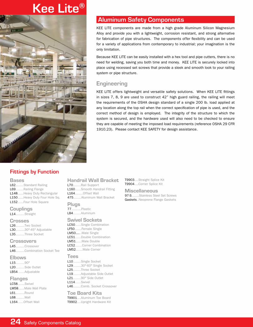
Kee lite®
engineeringKee lite offers lightweight and versatile safety solutions. when Kee lite fittings in sizes 7, 8, 9 are used to construct 42” high guard railing, the railing will meet the requirements of the osha design standard of a single 200 lb. load applied at any location along the top rail when the correct specification of pipe is used, and the correct method of design is employed. the integrity of the structure to which the system is secured, and the hardware used will also need to be checked to ensure they are capable of meeting the imposed load requirements (reference osha 29 cfr 1910.23). please contact Kee safety for design assistance.
aluminum Safety ComponentsKee lite components are made from a high grade aluminum silicon magnesium alloy and provide you with a lightweight, corrosion resistant, and strong alternative for fabrication of pipe structures. the components offer flexibility and can be used for a variety of applications from contemporary to industrial; your imagination is the only limitation.
Because Kee lite can be easily installed with a hex tool and pipe cutters, there is no need for welding, saving you both time and money. Kee lite is securely locked into place using recessed set screws that provide a sleek and smooth look to your railing system or pipe structure.
Basesl62........standard railingl69........railing flangel148......heavy duty rectangularl150......heavy duty four hole sq.l152......four hole square
Couplingsl14.........straight
Crossesl26.........two socketl30.........30°-45° adjustablel35.........three socket
Crossoversl45.........crossoverl46.........combination socket tee
elbowsl15.........90° l20.........side outletlB54.......adjustable
Flangeslc58.......swivellm58......male wall platel61.........roundl68.........walll164......offset wall
Handrail Wall Bracketl70........rail supportl160......smooth handrail fittingl164........offset wall475........aluminum wall Bracket
plugs77..........plasticl84........aluminum
Swivel Socketslc50......single combinationlf50.......female singlelm50......male singlelc51......double combinationlm51......male doublelc52.......corner combinationlm52.......male corner
Teesl10........single socketl29........30°-60° single socketl25........three socketl19........adjustable side outletl21........90° side outletl114......swivell46........comb. socket crossover
Toe Board Kitst9901....aluminum toe Boardt9902....upright hardware Kit
t9903....straight splice Kitt9904....corner splice Kit
miscellaneous97-s........stainless steel set screwsgaskets..neoprene flange gaskets
Fittings by Function
24 Safety Components Catalog
www.keesafety.com 25
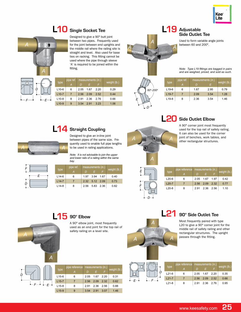
l10
typepipe ref. measurements (in.)
weight (lb.)a D e f
L10-6 6 2.05 1.67 2.20 0.29
L10-7 7 2.56 2.09 2.52 0.44
L10-8 8 2.91 2.36 2.76 0.66
L10-9 9 3.54 2.91 3.23 1.06
Single Socket Tee designed to give a 90° butt joint between two pipes. frequently used for the joint between end uprights and the middle rail where the railing site is straight and level. also used for base ties on racking. this fitting cannot be used where the pipe through sleeve ‘a’ is required to be joined within the fitting.a
a
f
D
e
l14
typepipe ref. measurements (in.)
weight (lb.)a D e f
L14-6 6 1.97 3.94 1.67 0.40
L14-7 7 2.32 5.12 2.09 0.73
L14-8 8 2.56 5.83 2.36 0.82
Straight Couplingdesigned to give an in-line joint between pipes of the same size. fre-quently used to enable full pipe lengths to be used in railing applications.
Note: It is not advisable to join the upper and lower rails of a railing within the same bay.
aa
f
D
e
l15
typepipe reference measurements (in.)
weight (lb.)a D e f
L15-6 6 2.05 1.67 2.20 0.31
L15-7 7 2.56 2.09 2.32 0.62
L15-8 8 2.91 2.36 2.56 0.88
L15-9 9 3.54 2.91 3.07 1.46
90° elbowa 90° elbow joint, most frequently used as an end joint for the top rail of safety railing on a level site.
a
a
f
D
e
60°-200°
l19
typepipe ref. measurements (in.)
weight (lb.)a D e
L19-6 6 1.67 2.95 0.79
L19-7 7 2.09 3.54 1.28
L19-8 8 2.36 3.54 1.46
adjustable Side outlet Teeused to form variable angle joints between 60 and 200°.
Note: Type L19 fittings are bagged in pairs and are weighed, priced, and sold as such.
aa
D
e
a
l20
typepipe reference measurements (in.)
weight (lb.)a D e f
L20-6 6 2.05 1.67 1.97 0.42
L20-7 7 2.56 2.09 2.32 0.77
L20-8 8 2.91 2.36 2.56 1.10
Side outlet elbow a 90° corner joint most frequently used for the top rail of safety railing. it can also be used for the corner joint of benches, work tables, and other rectangular structures.
a
a
f
D
e
a
l21
typepipe reference measurements (in.)
weight (lb.)a D e f
L21-6 6 2.05 1.67 2.20 0.35
L21-7 7 2.56 2.09 2.52 0.66
L21-8 8 2.91 2.36 2.76 0.95
90° Side outlet Tee most frequently paired with type l20 to give a 90° corner joint for the middle rail of safety railing and other rectangular structures. the upright passes through the fitting.a
a
f
D
e
a
26 Safety Components Catalog
l25 Three Socket Tee commonly used as the 90° joint between the top rail and an intermedi-ate upright on safety railing. as there are two socket set screws in the sleeve, this fitting can be used where a join is required in the horizontal pipe. the type l10 fitting can be used as an alternative when a join in the pipe is not required.
a
e
a
a
typepipe ref measurements (in.) weight (lb.)
a D e f G
L25-6 6 2.05 1.67 1.97 4.09 0.46
L25-7 7 2.56 2.09 2.32 5.12 0.77
L25-8 8 2.91 2.36 2.56 5.83 1.12
L25-9 9 3.54 2.91 3.07 7.09 1.81
G
D
f
l26 Two Socket Cross usually paired with type l25 to give a 90° joint between the middle rail and an intermediate upright on safety railing. the upright passes through the fitting.
a
a a
f
e
D typepipe reference measurements (in.)
weight (lb.)a D e f
L26-6 6 1.67 2.20 4.09 0.37
L26-7 7 2.09 2.52 5.12 0.62
L26-8 8 2.36 2.76 5.83 0.99
L26-9 9 2.91 3.23 7.09 1.46
l29 30°-60° Single Socket Tee this adjustable fitting is most fre-quently used for struts and braces. it can be used at any selected angle between 30° and 60°. suitable for connecting an angled staircase rail to a vertical upright.
a
a
G D
e
f typepipe measurements (in.)
weight (lb.)a D e f G
L29-7 7 3.23 3.74 1.06 2.07 0.70
L29-8 8 3.66 4.25 1.18 2.32 0.9030°-60°
l30 30°-45° adjustable Crossthis adjustable fitting can be used for railing on staircases between the mid-rail and intermediate upright which is required to remain vertical. it can be used at any selected angle between 30° and 45°.
a
a a
e
D
f
typepipe reference measurements (in.)
weight (lb.)a D e f
L30-7 7 8.46 2.07 2.13 1.15
L30-8 8 9.65 2.34 2.36 1.5230°-45°
l35 Three Socket Cross most frequently used to tie uprights with horizontal pipe in three direc-tions, all 90° to the upright. the upright passes through the fitting.
a
a
a
Gf
D
e
typepipe ref. measurements (in.)
weight (lb.)a D e f G
L35-6 6 2.20 4.09 2.05 1.67 0.68
l45 Crossoverdesigned to give a 90° offset cross-over joint. frequently used on safety railing utilizing a continuous horizontal rail, minimizing pipe cuts to reduce costs. type l45 may also be used to allow intermediate levels on racks.
Note: Pipe cannot be joined with this fitting.
a
a
e
D
typepipe reference measurements (in.)
weight (lb.)a B C D e f
L45-6 6 1.73 1.57 0.26
L45-7 7 2.13 1.97 0.68
L45-8 8 2.40 2.20 0.77
Swivel Fittingstypes lf50, lm50, lm51, lm52, and lm58 are known as swivel fittings and can
be assembled as types lc50, lc51, lc52, and lc58 or supplied as separate items. they are frequently used for bracing but can also overcome problems where joints are required at angles other than those achieved by fixed angle
fittings. when making 'c' fittings, or combination fittings, types lf50 can be combined with different sizes of type 'm' fittings, or male components. warning:
An entire structure should not be constructed from swivel fittings, as they would not provide sufficient stability or rigidity in the structure. Types LM50, LM51, LM52
and LM58 can also be used separately to secure various types of in-fill panel. These fittings are not designed to take bending moments.
www.keesafety.com 27
lm50 male Single Swivel Socket memberThe male portion of a swivel com-ponent combination. The fitting can also be used to attach flat panels to tubular structures.
a
e
D
f
G
l46 Combination Socket Tee and Crossover used on racking to join horizontal car-rying rails to the upright, leaving the socket to take a horizontal pipe out-side the upright. on pallet racking, it is preferable to have the carrying rails inside the upright.
a
aa
e
D
e f
HG
typepipe ref. measurements (in.)
wt. (lb.)a D e f G H
L46-6 6 1.67 1.57 2.05 1.73 1.97 0.42
lC50 Single Swivel Socketa complete combination swivel fitting, variable through 170°. see type lm50 and type lf50 for measure-ments.
Note: Swivel fittings are not designed to resist bending loads. a structure should not be designed entirely of swivel fittings as they will not provide sufficient stability for the structure.
a
B
typepipe reference
weight (lb.)a B
LC50-66 6 6 0.68
LC50-77 7 7 0.90
LC50-88 8 8 1.10
85°
lF50 Female Singe Swivel Socket member the female part of a swivel compo-nent combination.
a
f
D
G
e
typepipe measurements (in.)
weight (lb.)a D e f G
LF50-6 6 1.97 1.67 2.95 0.38 0.37
LF50-7 7 2.32 2.09 3.54 0.38 0.55
LF50-8 8 2.56 2.36 3.54 0.38 0.64
typepipe measurements (in.)
wt (lb.)a D e f G Ø
LM50-6 6 1.97 1.73 1.85 0.43 0.38 0.26
LM50-7 7 2.32 2.00 1.97 0.43 0.38 1.33
LM50-8 8 2.56 2.36 2.17 0.43 0.38 1.44
lC51 Double Swivel Socketcomplete combination fitting. reduc-ing combinations of type lc51 are available in sizes 6, 7, and 8. see type lm51 and type lf50 for mea-surements.
a
CB
85°
85°
typepipe reference
weight (lb.)a B C
L20-666 6 6 6 1.26
L20-777 7 7 7 1.61
L20-888 8 8 8 1.88
28 Safety Components Catalog
lC52
typepipe reference
weight (lb.)a B C
LC52-666 6 6 6 1.06
LC52-777 7 7 7 1.48
LC52-888 8 8 8 1.76
Corner Swivel Socketcomplete combination component. reducing combinations of type lc52 are available in sizes 6, 7 and 8. see type lm52 and type lf50 for measurements.
85°
85°
a
B C
lm52 male Corner Swivel Socket memberone half of a combination component. this component can also be used for at-taching flat panels to tubular structures.
typepipe ref. measurements (in.)
wt. (lb.)a D e f G H Ø
LM52-6 6 1.97 1.73 1.85 0.43 1.67 0.38 0.35
LM52-7 7 2.32 2.00 1.97 0.43 2.09 0.38 0.51
LM52-8 8 2.56 2.36 2.17 0.43 2.36 0.38 0.60
Ø indicates diameter of rivet holes.
a
D
G
e
f
H
lm58
typemeasurements (in.)
rivet hole di. (in)
fixing hole di.
(in.)wt. (lb.)
D e f G H Ø Ø
LM58 3.38 1.32 0.31 2.07 1.78 0.38 0.45 0.37
male Wall platethe male part of a swivel fitting for at-taching angled tubing to flat surfaces.
GD
H
e
f
lC58
typepipe reference measurements (in.)
weight (lb.)a Ø
LC58-6 6 0.45 0.74
LC58-7 7 0.45 1.93
LC58-8 8 0.45 1.46
Ø indicates diameter of fixing holes.
a
Swivel Flangea swivel fitting for attachment of angled pipe to a flat surface. see type lm58 and type lf50 for measurements.
Note: This fitting is not recommended for use as a base flange to support guardrail or balustrades.
lB54
typepipe ref. measurements (in.)
weight (lb.)a D e f
LB54-6 6 1.97 1.67 3.94 0.77
LB54-7 7 2.28 2.17 4.69 1.43
LB54-8 8 2.56 2.36 5.16 1.61
adjustable elbowa swivel fitting designed as an in-line vari-able angle connection, adjustable from 45° to 200°. nut and bolt included.
a
f
D e45°-200°
a
lm51 male Double SwivelSocket memberone half of a combination compo-nent. this component can also be used for attaching flat panels to tubular structures.
a
e
DG
fH
typepipe measurements (in.)
wt (lb.)a D e f G H Ø
LM51-6 6 1.97 1.73 1.85 0.43 1.67 0.38 0.35
LM51-7 7 2.32 2.00 1.97 0.43 2.09 0.38 0.51
LM51-8 8 2.56 2.36 2.17 0.43 2.36 0.38 0.60
www.keesafety.com 29
l62
typepipe measurements (in.)
wt. (lb.)a D e f G H J Ø
L62-6 6 1.97 3.54 0.35 3.50 5.04 2.95 0.55 0.77
L62-7 7 2.18 3.54 0.35 4.02 5.51 3.23 0.55 0.94
L62-8 8 2.43 3.54 0.35 4.53 6.30 3.31 0.55 0.71
Standard Railing Flangethe type l62 flange should always be used to fix down guardrail and balustrades. holes are of sufficient diameter to give a good fixing with either a mechanical or chemi-cal anchor. two set screws in the vertical socket give greater stability to the upright. it is recommended that the fixing holes in the flange be in-line with the applied load. the pipe is able to pass through the base of the fitting.
a
J
GH
D
ef
Ø indicates diameter of fixing holes.
l68 Wall Flangeside palm flange for fixing guardrail and balustrades to walls, parapets, steps and ramps. the upright cannot drop through the socket.
Note: If the upright is required to pass through the fitting by machining out the base stop, the bottom fixing hole becomes unusable.
typepipe measurements (in.)
wt. (lb.)a D e f G H J K Ø
L68-6 6 1.67 2.80 2.52 0.95 2.95 3.98 0.31 0.45 0.53
L68-7 7 2.09 3.39 3.15 1.10 3.50 4.45 0.31 0.45 0.77
L68-8 8 2.36 3.78 3.62 1.22 3.94 5.04 0.31 0.45 0.95
Ø indicates diameter of fixing holes.
a
De
f
H J
G
K
Ø indicates diameter of fixing holes.
I
l70
typepipe measurements (in.) wt.
(lb.)a D e f G H I J Ø
L70-6 6 2.36 3.62 1.97 1.97 1.77 2.68 0.39 0.31 0.44
L70-7 7 2.68 4.13 2.32 2.36 2.13 3.19 0.39 0.31 0.75
L70-8 8 2.95 4.53 2.56 2.60 2.36 3.58 0.39 0.31 0.99
Rail Supportthis fitting, with holes provided for coun-tersunk flat head screw fixings only, is designed to carry handrails along walls or to fix structures back to walls. the pipe passes through the fitting and cannot be joined within the fitting. type 70 is also used to attach toe boards to the base of guardrail uprights.
a
DH
e
J
f
G
l61
typepipe ref. measurements (in.)
wt. (lb.)a D e f G H Ø
L61-6 6 1.67 1.97 0.31 3.94 1.93 0.25 0.46
L61-7 7 2.09 2.17 0.31 4.33 2.40 0.25 0.64
L61-8 8 2.36 2.36 0.31 4.72 2.64 0.25 0.71
Flangethis flange, with holes provided for coun-tersunk head fixing screws only, is used in structures where the fixing required is positional only. frequently used as a wall fixing bracket.
Note: L61 is not recommended for use as a base flange to support guard rail or balus-trades. Use Type L152 flange if a base flange is needed.
H
D
f
a
Ø indicates diameter of fixing holes.
M
PG N
O
e
If
KLH J
l69
typepipe ref. measurements (in.)
weight (lb.)a D e f G H I J K L M N O P Ø
L69-7 7 0.39 0.59 5.71 3.15 3.15 3.78 2.28 0.79 0.45 4.53 1.57 0.31 2.16 0.45 1.41
L69-8 8 0.39 0.59 6.30 3.54 3.15 4.41 2.28 0.79 0.45 5.12 1.97 0.31 2.24 0.45 1.65
Railing Flange with Toe Board adapterthe l69 railing flange has been designed for guard rail and balustrades and allows at-tachment of a toe board to the base. the base plate holes are of sufficient diameter to allow for attachment with either a mechanical or chemical anchor, the side plates have slotted holes to allow for a degree of sideways movement for ease of installa-tion. a toe board designed for used with type l69 railing flange is available from Kee safety. (see page 36.)
a
Ø indicates diameter of fixing holes.
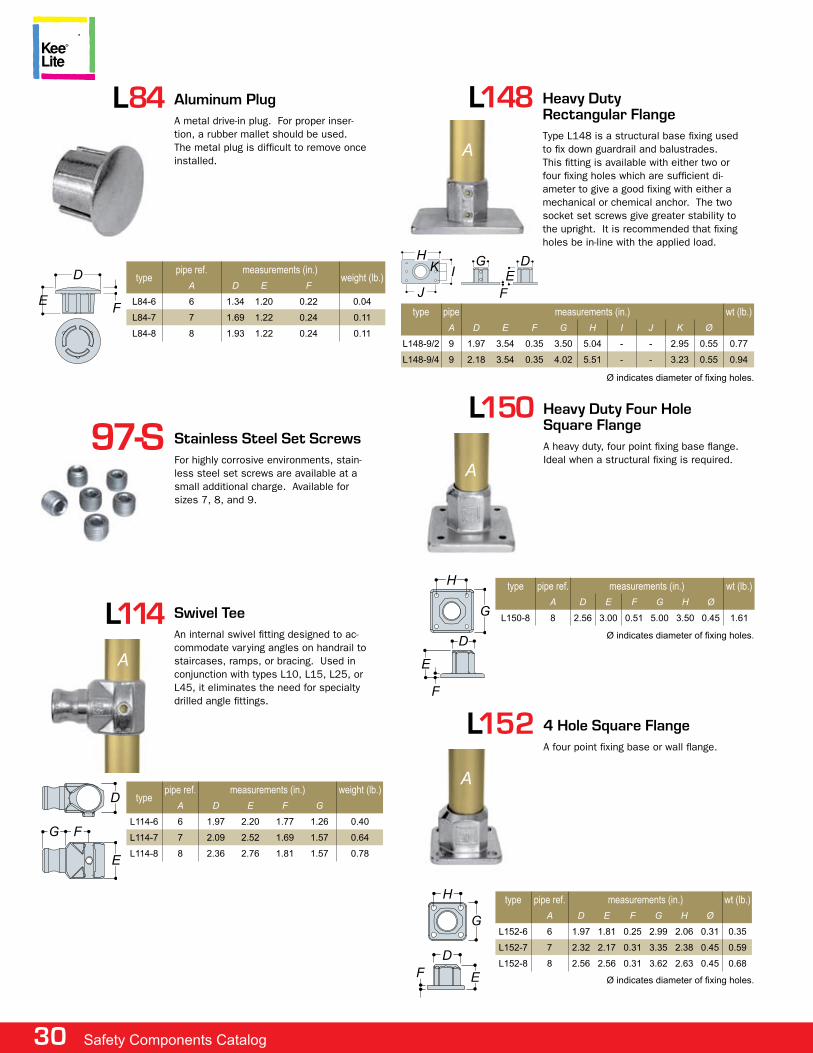
30 Safety Components Catalog
l114 Swivel Teean internal swivel fitting designed to ac-commodate varying angles on handrail to staircases, ramps, or bracing. used in conjunction with types l10, l15, l25, or l45, it eliminates the need for specialty drilled angle fittings.
typepipe ref. measurements (in.) weight (lb.)
a D e f G
L114-6 6 1.97 2.20 1.77 1.26 0.40
L114-7 7 2.09 2.52 1.69 1.57 0.64
L114-8 8 2.36 2.76 1.81 1.57 0.78
D
a
G f
e
Ø indicates diameter of fixing holes.
l148 Heavy Duty Rectangular Flangetype l148 is a structural base fixing used to fix down guardrail and balustrades. this fitting is available with either two or four fixing holes which are sufficient di-ameter to give a good fixing with either a mechanical or chemical anchor. the two socket set screws give greater stability to the upright. it is recommended that fixing holes be in-line with the applied load.
type pipe measurements (in.) wt (lb.)
a D e f G H I J K Ø
L148-9/2 9 1.97 3.54 0.35 3.50 5.04 - - 2.95 0.55 0.77
L148-9/4 9 2.18 3.54 0.35 4.02 5.51 - - 3.23 0.55 0.94
J
H G D
feIK
a
Heavy Duty Four Hole Square Flangea heavy duty, four point fixing base flange. ideal when a structural fixing is required.
l150
type pipe ref. measurements (in.) wt (lb.)
a D e f G H Ø
L150-8 8 2.56 3.00 0.51 5.00 3.50 0.45 1.61
a
Ø indicates diameter of fixing holes.D
e
f
G
H
l152 4 Hole Square Flangea four point fixing base or wall flange.
type pipe ref. measurements (in.) wt (lb.)
a D e f G H Ø
L152-6 6 1.97 1.81 0.25 2.99 2.06 0.31 0.35
L152-7 7 2.32 2.17 0.31 3.35 2.38 0.45 0.59
L152-8 8 2.56 2.56 0.31 3.62 2.63 0.45 0.68
Ø indicates diameter of fixing holes.
a
H
G
Def
Stainless Steel Set Screwsfor highly corrosive environments, stain-less steel set screws are available at a small additional charge. available for sizes 7, 8, and 9.
97-S
e
l84
typepipe ref. measurements (in.)
weight (lb.)a D e f
L84-6 6 1.34 1.20 0.22 0.04
L84-7 7 1.69 1.22 0.24 0.11
L84-8 8 1.93 1.22 0.24 0.11
aluminum pluga metal drive-in plug. for proper inser-tion, a rubber mallet should be used. the metal plug is difficult to remove once installed.
D
f
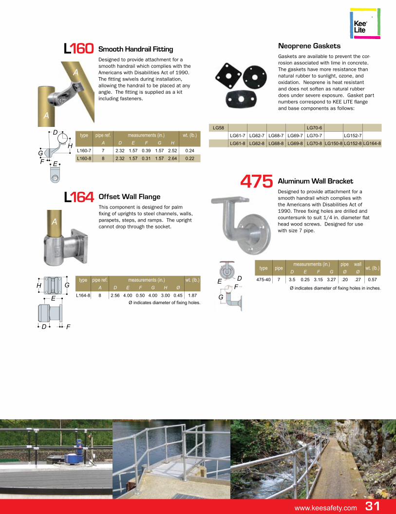
www.keesafety.com 31
l160 Smooth Handrail Fittingdesigned to provide attachment for a smooth handrail which complies with the americans with disabilities act of 1990. the fitting swivels during installation, allowing the handrail to be placed at any angle. the fitting is supplied as a kit including fasteners.
type pipe ref. measurements (in.) wt. (lb.)
a D e f G H
L160-7 7 2.32 1.57 0.39 1.57 2.52 0.24
L160-8 8 2.32 1.57 0.31 1.57 2.64 0.22
a
a
D
HGf e
Neoprene Gasketsgaskets are available to prevent the cor-rosion associated with lime in concrete. the gaskets have more resistance than natural rubber to sunlight, ozone, and oxidation. neoprene is heat resistant and does not soften as natural rubber does under severe exposure. gasket part numbers correspond to Kee lite flange and base components as follows:
LG58 LG70-6
LG61-7 LG62-7 LG68-7 LG69-7 LG70-7 LG152-7
LG61-8 LG62-8 LG68-8 LG69-8 LG70-8 LG150-8 LG152-8 LG164-8
l164
type pipe ref. measurements (in.) wt. (lb.)
a D e f G H Ø
L164-8 8 2.56 4.00 0.50 4.00 3.00 0.45 1.87
offset Wall Flangethis component is designed for palm fixing of uprights to steel channels, walls, parapets, steps, and ramps. the upright cannot drop through the socket.
H
a
G
e
D f
Ø indicates diameter of fixing holes.
475 aluminum Wall Bracketdesigned to provide attachment for a smooth handrail which complies with the americans with disabilities act of 1990. three fixing holes are drilled and countersunk to suit 1/4 in. diameter flat head wood screws. designed for use with size 7 pipe.
type pipemeasurements (in.) pipe wall
wt. (lb.)D e f G Ø Ø
475-40 7 3.5 0.25 3.15 3.27 .20 .27 0.57Def
GØ indicates diameter of fixing holes in inches.
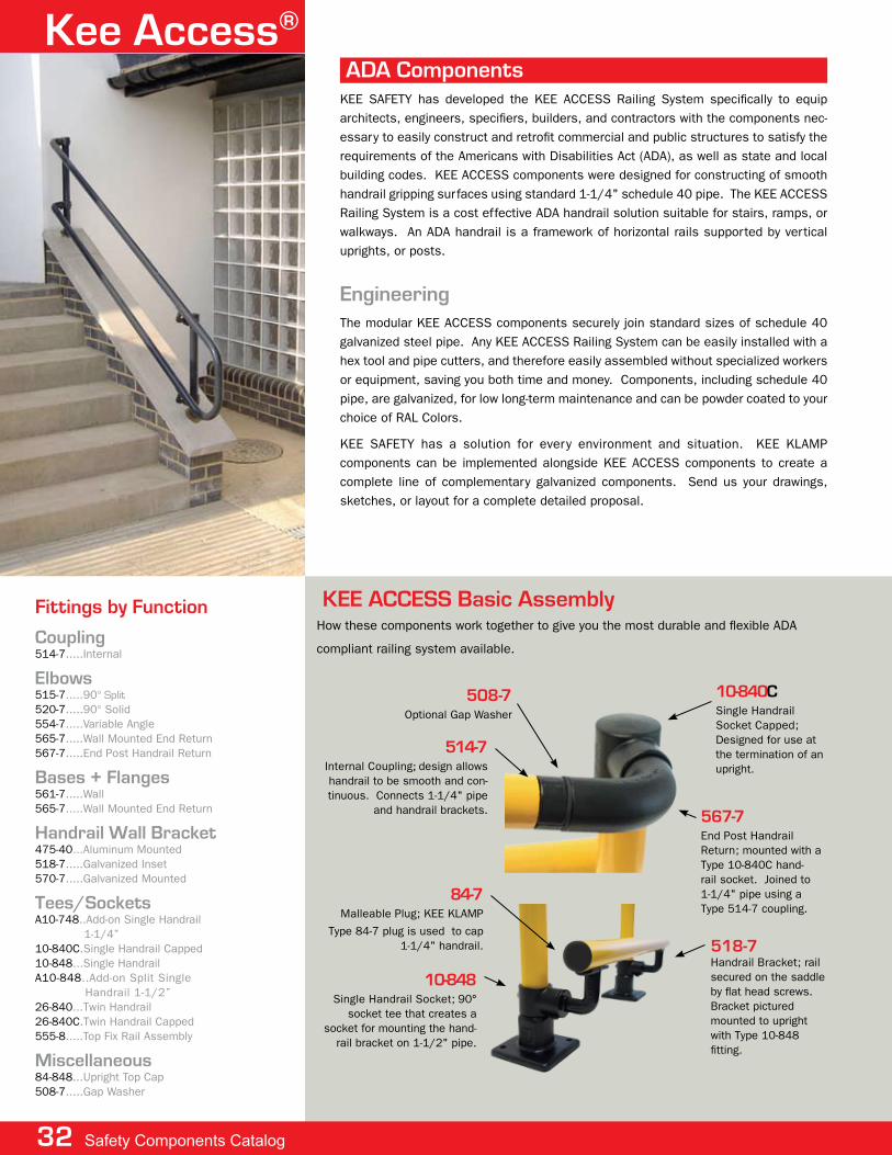
Kee access®
engineeringthe modular Kee access components securely join standard sizes of schedule 40 galvanized steel pipe. any Kee access railing system can be easily installed with a hex tool and pipe cutters, and therefore easily assembled without specialized workers or equipment, saving you both time and money. components, including schedule 40 pipe, are galvanized, for low long-term maintenance and can be powder coated to your choice of ral colors.
Kee safety has a solution for every environment and situation. Kee Klamp components can be implemented alongside Kee access components to create a complete line of complementary galvanized components. send us your drawings, sketches, or layout for a complete detailed proposal.
aDa ComponentsKee safety has developed the Kee access railing system specifically to equip architects, engineers, specifiers, builders, and contractors with the components nec-essary to easily construct and retrofit commercial and public structures to satisfy the requirements of the americans with disabilities act (ada), as well as state and local building codes. Kee access components were designed for constructing of smooth handrail gripping surfaces using standard 1-1/4" schedule 40 pipe. the Kee access railing system is a cost effective ada handrail solution suitable for stairs, ramps, or walkways. an ada handrail is a framework of horizontal rails supported by vertical uprights, or posts.
Coupling514-7.....internal
elbows515-7.....90° Split520-7.....90° solid554-7.....variable angle565-7.....wall mounted end return567-7.....end post handrail return
Bases + Flanges561-7.....wall565-7.....wall mounted end return
Handrail Wall Bracket475-40...aluminum mounted518-7.....galvanized inset570-7.....galvanized mounted
Tees/Socketsa10-748..add-on single handrail 1-1/4”10-840c.single handrail capped10-848...single handraila10-848..add-on split single handrail 1-1/2”26-840...twin handrail26-840c.twin handrail capped555-8.....top fix rail assembly
miscellaneous84-848...upright top cap508-7.....gap washer
Fittings by Function
32 Safety Components Catalog
10-840Csingle handrail socket capped; designed for use at the termination of an upright.
10-848single handrail socket; 90°
socket tee that creates a socket for mounting the hand-
rail bracket on 1-1/2" pipe.
84-7malleable plug; Kee Klamp
type 84-7 plug is used to cap 1-1/4" handrail.
508-7optional gap washer
567-7end post handrail return; mounted with a type 10-840c hand-rail socket. Joined to 1-1/4" pipe using a type 514-7 coupling.
Kee aCCeSS Basic assemblyhow these components work together to give you the most durable and flexible ada
compliant railing system available.
518-7handrail Bracket; rail secured on the saddle by flat head screws. Bracket pictured mounted to upright with type 10-848 fitting.
514-7internal coupling; design allows handrail to be smooth and con-tinuous. connects 1-1/4" pipe
and handrail brackets.
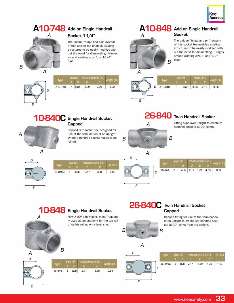
www.keesafety.com 33
a10-748
typepipe ref. measurements (in.)
weight (lb.)a B D e
A10-748 7 stub 2.99 2.09 0.62
add-on Single Handrail
Socket 1-1/4”the unique "hinge and pin" system of this socket tee enables existing structures to be easily modified with-out the need for dismantling. hinges around existing size 7, or 1-1/4" pipe.
a
B
10-840C
typepipe ref. measurements (in.)
wt. (lb.)a B D e
10-840C 8 stub 2.17 3.35 0.90
Single Handrail Socket Cappedcapped 90° socket tee designed for use at the termination of an upright where a handrail socket needs to be joined.
a
a
10-848 Single Handrail Socketnew a 90° elbow joint, most frequent-ly used as an end joint for the top rail of safety railing on a level site.
B
a
a10-848 add-on Single Handrail Socketthe unique "hinge and pin" system of this socket tee enables existing structures to be easily modified with-out the need for dismantling. hinges around existing size 8, or 1-1/2" pipe.
a
B
26-840
typepipe ref. measurements (in.)
weight (lb.)a B D e f
26-840 8 stub 2.17 1.89 4.33 0.97
Twin Handrail Socketfitting slips over upright to create to handrail sockets at 90° joints.
B
a
B
a
a
aa
e
D
e
D
typepipe ref. meas. (in.)
weight (lb.)a B D e
A10-848 8 stub 3.23 2.17 0.66
e
D
typepipe ref. measurements (in.)
weight (lb.)a B D e
10-848 8 stub 2.17 3.35 0.84
e
D
f
D
e
26-840C
type pipe ref. measurements (in.) wt. (lb.)
a B D e f
26-840C 8 stub 2.17 1.89 4.33 1.10
Twin Handrail Socket Cappedcapped fitting for use at the termination of an upright to create two handrail sock-ets at 90° joints from the upright.
a
B B
f
D
e
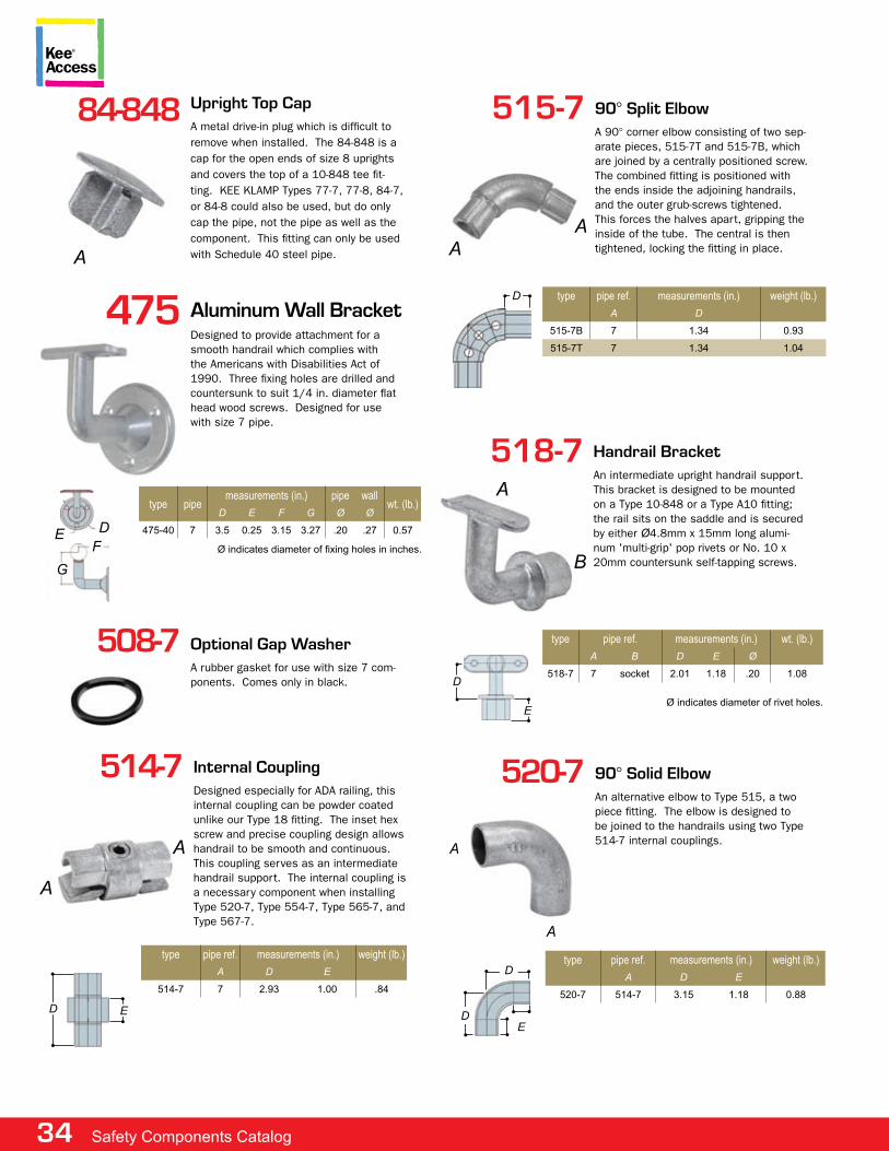
34 Safety Components Catalog
508-7 optional Gap Washera rubber gasket for use with size 7 com-ponents. comes only in black.
84-848 Upright Top Capa metal drive-in plug which is difficult to remove when installed. the 84-848 is a cap for the open ends of size 8 uprights and covers the top of a 10-848 tee fit-ting. Kee Klamp types 77-7, 77-8, 84-7, or 84-8 could also be used, but do only cap the pipe, not the pipe as well as the component. this fitting can only be used with schedule 40 steel pipe.a
515-7
type pipe ref. measurements (in.) weight (lb.)
a D
515-7B 7 1.34 0.93
515-7T 7 1.34 1.04
90° Split elbowa 90° corner elbow consisting of two sep-arate pieces, 515-7t and 515-7B, which are joined by a centrally positioned screw. the combined fitting is positioned with the ends inside the adjoining handrails, and the outer grub-screws tightened. this forces the halves apart, gripping the inside of the tube. the central is then tightened, locking the fitting in place.
aa
D
518-7
type pipe ref. measurements (in.) wt. (lb.)
a B D e Ø
518-7 7 socket 2.01 1.18 .20 1.08
Handrail Bracketan intermediate upright handrail support. this bracket is designed to be mounted on a type 10-848 or a type a10 fitting; the rail sits on the saddle and is secured by either Ø4.8mm x 15mm long alumi-num 'multi-grip' pop rivets or no. 10 x 20mm countersunk self-tapping screws.
a
B
eØ indicates diameter of rivet holes.
D
514-7
type pipe ref. measurements (in.) weight (lb.)
a D e
514-7 7 2.93 1.00 .84
Internal Couplingdesigned especially for ada railing, this internal coupling can be powder coated unlike our type 18 fitting. the inset hex screw and precise coupling design allows handrail to be smooth and continuous. this coupling serves as an intermediate handrail support. the internal coupling is a necessary component when installing type 520-7, type 554-7, type 565-7, and type 567-7.
a
a
eD
520-7 90° Solid elbowan alternative elbow to type 515, a two piece fitting. the elbow is designed to be joined to the handrails using two type 514-7 internal couplings.
type pipe ref. measurements (in.) weight (lb.)
a D e
520-7 514-7 3.15 1.18 0.88
a
De
D
a
475 aluminum Wall Bracketdesigned to provide attachment for a smooth handrail which complies with the americans with disabilities act of 1990. three fixing holes are drilled and countersunk to suit 1/4 in. diameter flat head wood screws. designed for use with size 7 pipe.
type pipemeasurements (in.) pipe wall
wt. (lb.)D e f G Ø Ø
475-40 7 3.5 0.25 3.15 3.27 .20 .27 0.57Def
GØ indicates diameter of fixing holes in inches.
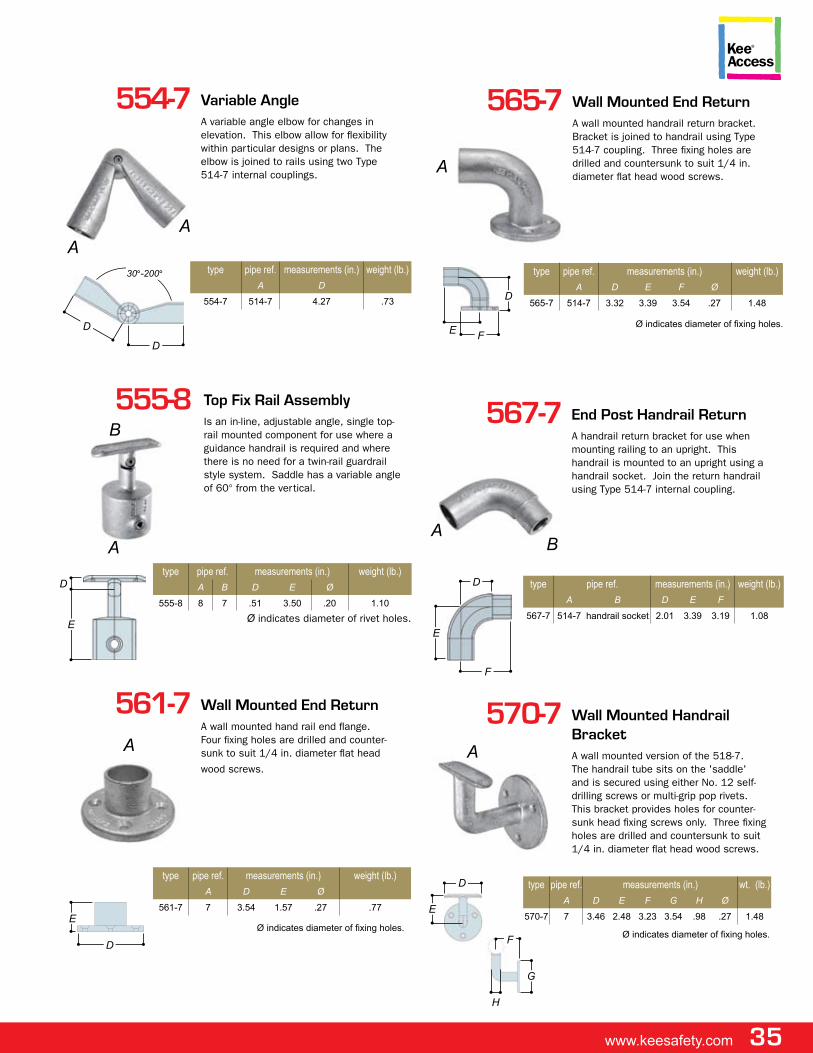
www.keesafety.com 35
555-8
type pipe ref. measurements (in.) weight (lb.)
a B D e Ø
555-8 8 7 .51 3.50 .20 1.10
Top Fix Rail assemblyis an in-line, adjustable angle, single top-rail mounted component for use where a guidance handrail is required and where there is no need for a twin-rail guardrail style system. saddle has a variable angle of 60° from the vertical.
a
B
Ø indicates diameter of rivet holes.
D
e
554-7
type pipe ref. measurements (in.) weight (lb.)
a D
554-7 514-7 4.27 .73
Variable anglea variable angle elbow for changes in elevation. this elbow allow for flexibility within particular designs or plans. the elbow is joined to rails using two type 514-7 internal couplings.
aa
D
D
30°-200°
565-7
type pipe ref. measurements (in.) weight (lb.)
a D e f Ø
565-7 514-7 3.32 3.39 3.54 .27 1.48
Wall mounted end Returna wall mounted handrail return bracket. Bracket is joined to handrail using type 514-7 coupling. three fixing holes are drilled and countersunk to suit 1/4 in. diameter flat head wood screws.
a
Ø indicates diameter of fixing holes.e
D
f
567-7
type pipe ref. measurements (in.) weight (lb.)
a B D e f
567-7 514-7 handrail socket 2.01 3.39 3.19 1.08
end post Handrail Returna handrail return bracket for use when mounting railing to an upright. this handrail is mounted to an upright using a handrail socket. Join the return handrail using type 514-7 internal coupling.
Ba
e
D
f
570-7
type pipe ref. measurements (in.) wt. (lb.)
a D e f G H Ø
570-7 7 3.46 2.48 3.23 3.54 .98 .27 1.48
Wall mounted Handrail Bracketa wall mounted version of the 518-7. the handrail tube sits on the 'saddle' and is secured using either no. 12 self-drilling screws or multi-grip pop rivets. this bracket provides holes for counter-sunk head fixing screws only. three fixing holes are drilled and countersunk to suit 1/4 in. diameter flat head wood screws.
a
Ø indicates diameter of fixing holes.
e
D
f
H
G
561-7
type pipe ref. measurements (in.) weight (lb.)
a D e Ø
561-7 7 3.54 1.57 .27 .77
Wall mounted end Returna wall mounted hand rail end flange. four fixing holes are drilled and counter-sunk to suit 1/4 in. diameter flat head
wood screws.
a
Ø indicates diameter of fixing holes.
D
e
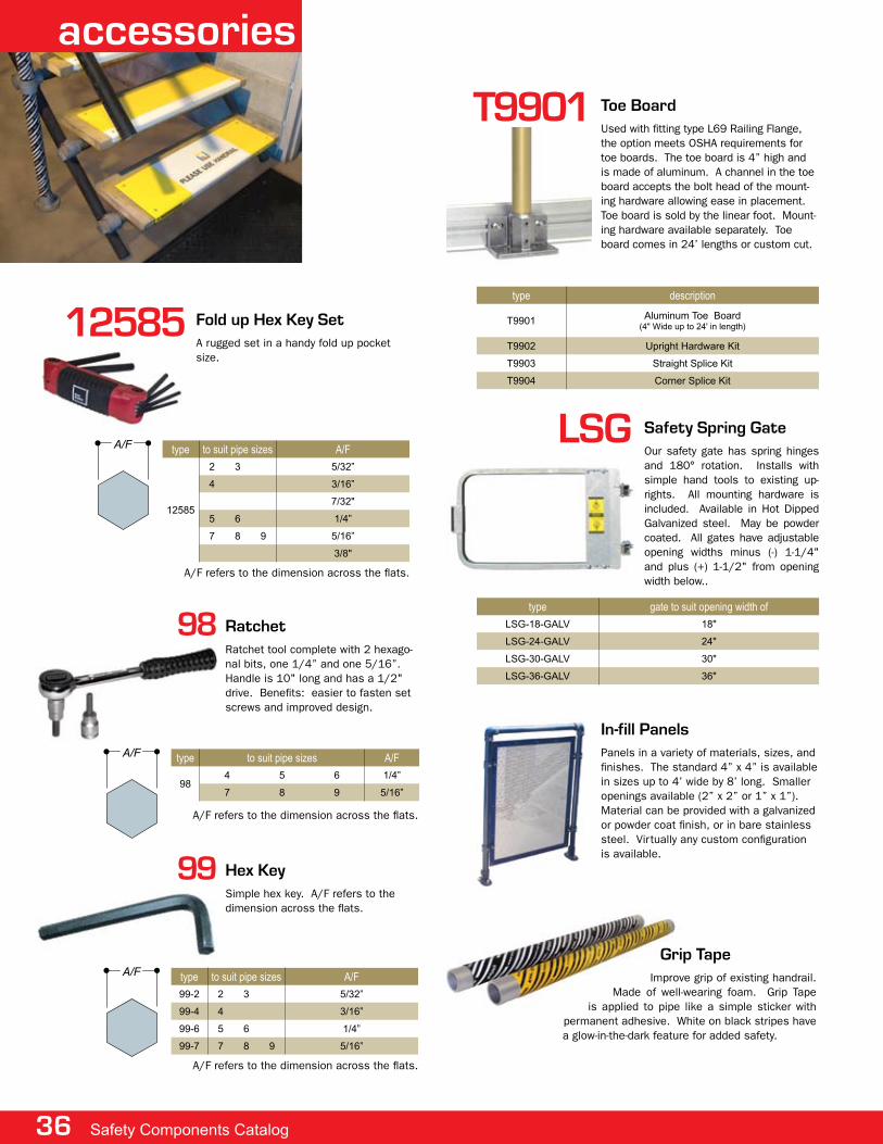
36 Safety Components Catalog
In-fill panelspanels in a variety of materials, sizes, and finishes. the standard 4” x 4” is available in sizes up to 4’ wide by 8’ long. smaller openings available (2” x 2” or 1” x 1”). material can be provided with a galvanized or powder coat finish, or in bare stainless steel. virtually any custom configuration is available.
Grip Tapeimprove grip of existing handrail.
made of well-wearing foam. grip tape is applied to pipe like a simple sticker with
permanent adhesive. white on black stripes have a glow-in-the-dark feature for added safety.
98
type to suit pipe sizes A/F
984 5 6 1/4”
7 8 9 5/16”
Ratchetratchet tool complete with 2 hexago-nal bits, one 1/4” and one 5/16”. handle is 10" long and has a 1/2" drive. Benefits: easier to fasten set screws and improved design.
a/f
a/f refers to the dimension across the flats.
99 Hex Keysimple hex key. a/f refers to the dimension across the flats.
type to suit pipe sizes A/F
99-2 2 3 5/32”
99-4 4 3/16”
99-6 5 6 1/4”
99-7 7 8 9 5/16”
a/f
a/f refers to the dimension across the flats.
accessories
Toe Boardused with fitting type l69 railing flange, the option meets osha requirements for toe boards. the toe board is 4” high and is made of aluminum. a channel in the toe board accepts the bolt head of the mount-ing hardware allowing ease in placement. toe board is sold by the linear foot. mount-ing hardware available separately. toe board comes in 24’ lengths or custom cut.
T9901
type description
T9901 Aluminum Toe Board(4" Wide up to 24' in length)
T9902 Upright Hardware Kit
T9903 Straight Splice Kit
T9904 Corner Splice Kit
12585 Fold up Hex Key Seta rugged set in a handy fold up pocket size.
type to suit pipe sizes A/F
12585
2 3 5/32”
4 3/16”
7/32"
5 6 1/4”
7 8 9 5/16”
3/8"
a/f
a/f refers to the dimension across the flats.
Safety Spring Gateour safety gate has spring hinges and 180° rotation. installs with simple hand tools to existing up-rights. all mounting hardware is included. available in hot dipped galvanized steel. may be powder coated. all gates have adjustable opening widths minus (-) 1-1/4" and plus (+) 1-1/2" from opening width below..
lSG
type gate to suit opening width of
LSG-18-GALV 18"
LSG-24-GALV 24"
LSG-30-GALV 30"
LSG-36-GALV 36"
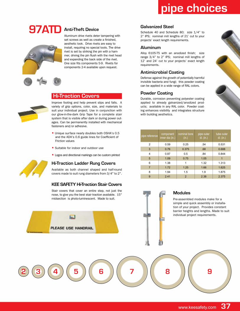
www.keesafety.com 37
65432 7 8 9
Galvanized Steelschedule 40 and schedule 80; size 1/4” to 2” ips; nominal mill lengths of 21’ cut to your projects’ exact length requirements.
aluminumalloy 6105-t5 with an anodized finish; size range 3/4” to 2” ips; nominal mill lengths of 12’ and 24’ cut to your projects’ exact length requirements.
antimicrobial Coatingdefense against the growth of potentially harmful invisible bacteria and fungi; this powder coating can be applied in a wide range of ral colors.
powder Coatingdurable, corrosion preventing polyester coating applied to already galvanized/anodized prod-ucts; available in any ral color. powder coat-ing enhances visibility and integrates structure with building aesthetics.
modulespre-assembled modules make for a simple and quick assembly or installa-tion of your project. provides constant barrier heights and lengths. made to suit individual project requirements.
pipe referencecomponent
inner dia (in.)nominal bore
(in.)pipe outer
di. (in.)tube outer
di. (in.)
2 0.59 0.25 .54 0.531
3 0.76 0.375 .68 0.688
4 0.87 0.5 .84 0.844
5 1.09 0.75 1.05 1
6 1.38 1 1.32 1.313
7 1.72 1.25 1.66 1.625
8 1.94 1.5 1.9 1.875
9 2.41 2 2.38 2.375
pipe choices
Hi-Traction Coversimprove footing and help prevent slips and falls. a variety of grip options, color, size, and materials to suit your individual project. use in conjunction with our glow-in-the-dark grip tape for a complete stair system that is visible after dark or during power out-ages. can be permanently installed with mechanical fasteners and/or adhesive.
• unique surface nearly doubles both osha's 0.5 and the ada's 0.6 guide lines for coefficient of friction values
• suitable for indoor and outdoor use
• logos and directional markings can be custom printed
Hi-Traction ladder Rung Coversavailable as both channel shaped and half-round covers made to suit rung diameters from 3/4" to 2".
Kee SaFeTy Hi-Traction Stair Coversstair covers that cover an entire step, not just the nose, to give you the best stair traction available. 15" midsection is photo-luminescent. made to suit.
anti-Theft Devicealuminum drive rivets deter tampering with set screws as well as create a finished, aesthetic look. drive rivets are easy to install, requiring no special tools. the drive rivet is set by striking the pin with a ham-mer, driving the pin flush with the rivet head and expanding the back side of the rivet. one size fits components 5-9. rivets for components 2-4 available upon request.
97aTD
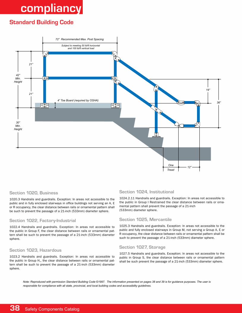
38 Safety Components Catalog
compliancy
Section 1020, Business1020.3 handrails and guardrails. exception: in areas not accessible to the public and in fully enclosed stairways in office buildings not serving an a, e or r occupancy, the clear distance between rails or ornamental pattern shall be such to prevent the passage of a 21-inch (533mm) diameter sphere.
Section 1022, Factory-Industrial1022.4 handrails and guardrails. exception: in areas not accessible to the public in group f, the clear distance between rails or ornamental pat-tern shall be such to prevent the passage of a 21-inch (533mm) diameter sphere.
Section 1023, Hazardous1023.2 handrails and guardrails. exception: in areas not accessible to the public in group h,, the clear distance between rails or ornamental pat-tern shall be such to prevent the passage of a 21-inch (533mm) diameter sphere.
Section 1024, Institutional1024.2.11 handrails and guardrails. exception: in areas not accessible to the public in group i restrained the clear distance between rails or orna-mental pattern shall prevent the passage of a 21-inch(533mm) diameter sphere.
Section 1025, mercantile1025.3 handrails and guardrails. exception: in areas not accessible to the public and fully enclosed stairways in group m, not serving a group a, e or r occupancy, the clear distance between rails or ornamental pattern shall be such to prevent the passage of a 21-inch (533mm) diameter sphere.
Section 1027, Storage1027.5 handrails and guardrails. exception: in areas not accessible to the public in group s, the clear distance between rails or ornamental pattern shall be such prevent the passage of a 21-inch (533mm) diameter sphere.
Note: Reproduced with permission Standard Building Code ©1997. the information presented on pages 38 and 39 is for guidance purposes. the user is responsible for compliance with all state, provincial, and local building codes and accessibility guidelines.
Standard Building Code
36”
tread12”
19”
30”Min.
Height
42”Min.
Height
21”
21”
72” Recommended Max. Post Spacing
Subject to meeting 50 lb/ft horizontal and 100 lb/ft vertical load
4” toe Board (required by OSHa)
One

30”Min.
Height
42”Min.
Height
72” Recommended Max. Post Spacing
Subject to meeting 50 lb./ft. horizontal and 100 lb/ft vertical load
4” dia. sphere shall not pass up to 34"
8” dia. sphere shall not pass
sphere 8” dia. shall not pass
34”
42”
www.keesafety.com 39
IBC/ICC
oSHa
International Building Code/International Code Council
oSHa Standard pipe Railing: 1910.23 Guarding floor and wall openings and holes
1013.1 Guards: Where Requiredguards shall be located along open-sided walking surfaces, mezzanines, industrial equipment platforms, stairways, ramps and landings which are located more than 30 inches (762 mm) above the floor or grade below. guards shall be adequate in strength and attachment in accordance with section 1607.7. where glass is used to provide a guard or as a portion of a guard system, the guard shall also comply with section 2407. guards shall also be located along glazed sides of stairways, ramps and landings that are located more than 30 inches (762 mm) above floor grade below where the glazing
provided does not meet the strength and attachments in section 1607.7.
1003.2.12.1 Guards: Heightguards shall form a protective barrier not less than 42 inches (1067 mm) high, mea-sured vertically above the leading edge of the tread, adjacent walking surface or adjacent seatboard.
Note: Information above is non-exhaustive. the user is responsible for compliance with all state, provincial, and local build-ing codes and accessibility guidelines. Please consult the most current publication of the following for complete IBC/ICC guidelines. Copyright 2006, International Code Council, Inc., Country Club Hills, Illinois. International Building Code 2006. Reproduced with permission. all rights reserved.
48”Min.
Height
42”Min.
Height
8’ Max. distance between posts when using size 8 pipe
4” Toe Board 1/4” or less above floor 30-42”Min.
Height
equal
equal
Min. 4 Risers
equal
equal
1910.23 (e)(1)a standard railing shall consist of top rail, intermediate rail, and posts, and shall have a vertical height of 42” nominal from upper surface of top rail to floor, platform, runway, or ramp level.
1910.23 (e) (ii)for pipe railings, posts, and top and intermediate railings shall be at least 1-1/2” nominal diameter with posts spaced not more than 8’ on centers.
1910.23 (e)(3)(iv)the anchoring of posts and framing of members for railings of all types shall be of such construction that the completed structure shall be capable of withstanding a load of at least 200 pounds applied in any direction at any point on the top rail.
1910.23 (e)(4)a standard toe board shall be 4” nominal in vertical height from its top edge to the level of the floor, plat-form, runway, or ramp. it shall be securely fastened in place and with not more than 1/4” clearance above floor level. (C)(4) the railing shall be provided with the toe board wherever, beneath open sides, (i) persons can pass, (ii) there is moving machinery, or (iii) there is equipment with which falling materials could create a hazard.
1003.2.12.2 Guards:openings limitationsopen guards shall have a balusters or orna-mental patterns such that a 4-inch-diameter (102 mm) sphere cannot pass through any opening up to a height of 34 inches (864 mm). from height of 34 inches (864 mm) to 42 inches (1067 mm) above the adjacent walking surfaces, a sphere 8 inches (203 mm) in diameter shall not pass.
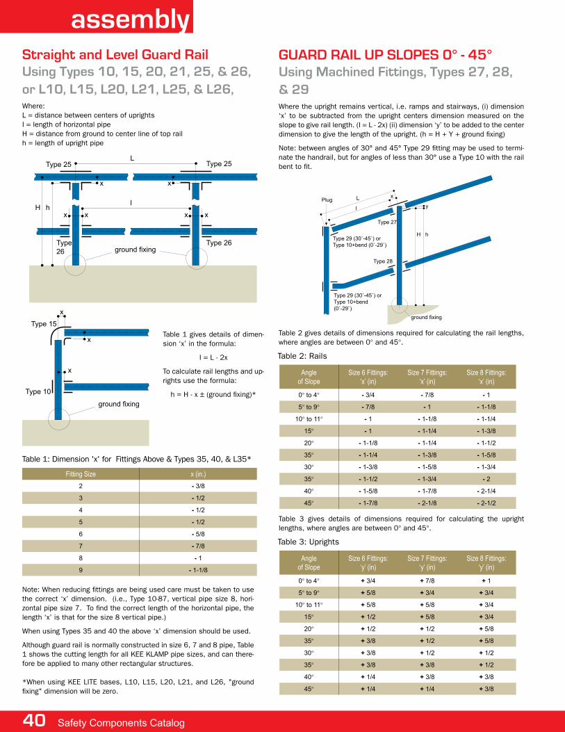
40 Safety Components Catalog
assemblyStraight and level Guard RailUsing Types 10, 15, 20, 21, 25, & 26, or l10, l15, l20, l21, l25, & l26,where:l = distance between centers of uprightsi = length of horizontal pipeh = distance from ground to center line of top railh = length of upright pipe
L
lH h
Type 25
Type 15
Type 10
Type
26
Type 26
Type 25
x x
x
x
x
x
x
x x
ground fixing
ground fixing
table 1 gives details of dimen-sion ‘x’ in the formula:
i = l - 2x
to calculate rail lengths and up-rights use the formula:
h = h - x ± (ground fixing)*
Fitting Size x (in.)
2 - 3/8
3 - 1/2
4 - 1/2
5 - 1/2
6 - 5/8
7 - 7/8
8 - 1
9 - 1-1/8
note: when reducing fittings are being used care must be taken to use the correct ‘x’ dimension. (i.e., type 10-87, vertical pipe size 8, hori-zontal pipe size 7. to find the correct length of the horizontal pipe, the length ‘x’ is that for the size 8 vertical pipe.)
when using types 35 and 40 the above ‘x’ dimension should be used.
although guard rail is normally constructed in size 6, 7 and 8 pipe, table 1 shows the cutting length for all Kee Klamp pipe sizes, and can there-fore be applied to many other rectangular structures.
*when using Kee lite bases, l10, l15, l20, l21, and l26, "ground fixing" dimension will be zero.
table 1: dimension 'x' for fittings above & types 35, 40, & l35*
GUaRD RaIl Up SlopeS 0° - 45°Using machined Fittings, Types 27, 28, & 29where the upright remains vertical, i.e. ramps and stairways, (i) dimension ‘x’ to be subtracted from the upright centers dimension measured on the slope to give rail length. (i = l - 2x) (ii) dimension ‘y’ to be added to the center dimension to give the length of the upright. (h = h + y + ground fixing)
note: between angles of 30° and 45° type 29 fitting may be used to termi-nate the handrail, but for angles of less than 30° use a type 10 with the rail bent to fit.
L x
l
Type 27
Type 29 (30˚-45˚) or
Type 10+bend (0˚-29˚)
Type 28
H h
y
ground fixing
Plug
Type 29 (30˚-45˚) or
Type 10+bend
(0˚-29˚)
Angleof Slope
Size 6 Fittings: ‘x’ (in)
Size 7 Fittings:‘x’ (in)
Size 8 Fittings:‘x’ (in)
0° to 4° - 3/4 - 7/8 - 1
5° to 9° - 7/8 - 1 - 1-1/8
10° to 11° - 1 - 1-1/8 - 1-1/4
15° - 1 - 1-1/4 - 1-3/8
20° - 1-1/8 - 1-1/4 - 1-1/2
35° - 1-1/4 - 1-3/8 - 1-5/8
30° - 1-3/8 - 1-5/8 - 1-3/4
35° - 1-1/2 - 1-3/4 - 2
40° - 1-5/8 - 1-7/8 - 2-1/4
45° - 1-7/8 - 2-1/8 - 2-1/2
table 2: rails
table 2 gives details of dimensions required for calculating the rail lengths, where angles are between 0° and 45°.
Angleof Slope
Size 6 Fittings:‘y’ (in)
Size 7 Fittings:‘y’ (in)
Size 8 Fittings:‘y’ (in)
0° to 4° + 3/4 + 7/8 + 1
5° to 9° + 5/8 + 3/4 + 3/4
10° to 11° + 5/8 + 5/8 + 3/4
15° + 1/2 + 5/8 + 3/4
20° + 1/2 + 1/2 + 5/8
35° + 3/8 + 1/2 + 5/8
30° + 3/8 + 1/2 + 1/2
35° + 3/8 + 3/8 + 1/2
40° + 1/4 + 3/8 + 3/8
45° + 1/4 + 1/4 + 3/8
table 3: uprights
table 3 gives details of dimensions required for calculating the upright lengths, where angles are between 0° and 45°.
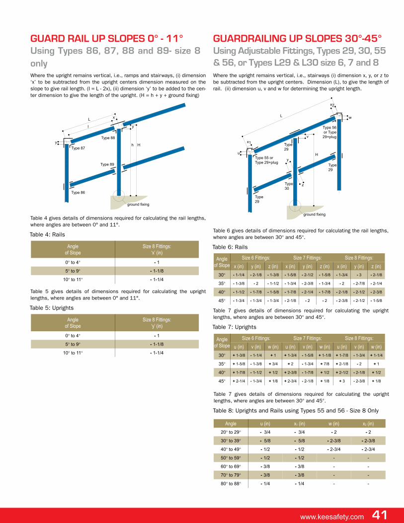
www.keesafety.com 41
GUaRD RaIl Up SlopeS 0° - 11°Using Types 86, 87, 88 and 89- size 8 onlywhere the upright remains vertical, i.e., ramps and stairways, (i) dimension ‘x’ to be subtracted from the upright centers dimension measured on the slope to give rail length. (i = l - 2x), (ii) dimension ‘y’ to be added to the cen-ter dimension to give the length of the upright. (h = h + y + ground fixing)
L
x2
w
v
y
zType
30
Type 55 or
Type 29+plug
Type
29
Type
29
Type 56
or Type
29+plug
Type
29
H
ground fixing
x1
u
Angleof Slope
Size 8 Fittings:‘x’ (in)
0° to 4° - 1
5° to 9° - 1-1/8
10° to 11° - 1-1/4
table 4: rails
table 4 gives details of dimensions required for calculating the rail lengths, where angles are between 0° and 11°.
Angleof Slope
Size 8 Fittings:‘y’ (in)
0° to 4° - 1
5° to 9° - 1-1/8
10° to 11° - 1-1/4
table 5: uprights
table 5 gives details of dimensions required for calculating the upright lengths, where angles are between 0° and 11°.
GUaRDRaIlING Up SlopeS 30°-45°Using adjustable Fittings, Types 29, 30, 55 & 56, or Types l29 & l30 size 6, 7 and 8where the upright remains vertical, i.e., stairways (i) dimension x, y, or z to be subtracted from the upright centers. dimension (l), to give the length of rail. (ii) dimension u, v and w for determining the upright length.
Lx
l
Type 87
Type 89
H
y
y
ground fixing
Type 86
Type 88
h
Angleof Slope
Size 6 Fittings: Size 7 Fittings: Size 8 Fittings:
x (in) y (in) z (in) x (in) y (in) z (in) x (in) y (in) z (in)
30° - 1-1/4 - 2-1/8 - 1-3/8 - 1-5/8 - 2-1/2 - 1-5/8 - 1-3/4 - 3 - 2-1/8
35° - 1-3/8 - 2 - 1-1/2 - 1-3/4 - 2-3/8 - 1-3/4 - 2 - 2-7/8 - 2-1/4
40° - 1-1/2 - 1-7/8 - 1-5/8 - 1-7/8 - 2-1/4 - 1-7/8 - 2-1/8 - 2-1/2 - 2-3/8
45° - 1-3/4 - 1-3/4 - 1-3/4 - 2-1/8 - 2 - 2 - 2-3/8 - 2-1/2 - 1-5/8
table 6: rails
table 6 gives details of dimensions required for calculating the rail lengths, where angles are between 30° and 45°.
Angle u (in) x1 (in) w (in) x2 (in)
20° to 29° - 3/4 - 3/4 - 2 - 2
30° to 39° - 5/8 - 5/8 - 2-3/8 - 2-3/8
40° to 49° - 1/2 - 1/2 - 2-3/4 - 2-3/4
50° to 59° - 1/2 - 1/2 - -
60° to 69° - 3/8 - 3/8 - -
70° to 79° - 3/8 - 3/8 - -
80° to 88° - 1/4 - 1/4 - -
table 7: uprights
table 7 gives details of dimensions required for calculating the upright lengths, where angles are between 30° and 45°.
Angleof Slope
Size 6 Fittings: Size 7 Fittings: Size 8 Fittings:
u (in) v (in) w (in) u (in) v (in) w (in) u (in) v (in) w (in)
30° + 1-3/8 - 1-1/4 + 1 + 1-3/4 - 1-5/8 + 1-1/8 + 1-7/8 - 1-3/4 + 1-1/4
35° + 1-5/8 - 1-3/8 + 3/4 + 2 - 1-3/4 + 7/8 + 2-1/8 - 2 + 1
40° + 1-7/8 - 1-1/2 + 1/2 + 2-3/8 - 1-7/8 + 1/2 + 2-1/2 - 2-1/8 + 1/2
45° + 2-1/4 - 1-3/4 + 1/8 + 2-3/4 - 2-1/8 + 1/8 + 3 - 2-3/8 + 1/8
table 8: uprights and rails using types 55 and 56 - size 8 only
table 7 gives details of dimensions required for calculating the upright lengths, where angles are between 30° and 45°.
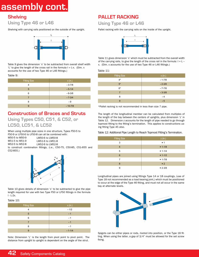
42 Safety Components Catalog
assembly cont.ShelvingUsing Type 46 or l46shelving with carrying rails positioned on the outside of the upright.
Fitting Size x (in.)
4 - 3-7/8
5 - 5-1/4
6 - 6-3/8
7 - 7-3/4
8 - 9
9 - 10-7/8
table 9:
palleT RaCKINGUsing Type 46 or l46pallet racking with the carrying rails on the inside of the upright.
L
l
table 11:
table 11 gives dimension ‘x’ which must be subtracted from the overall width of the carrying rails, to give the length of the cross rail in the formula: i = l – x. (dim. x accounts for the use of two type 46 or l46 fittings.)
table 12: additional pipe length to reach topmost fitting's termination.
table 9 gives the dimension ‘x’ to be subtracted from overall shelf width ‘l’ to give the length of the cross rail in the formula i = l-x. (dim. xaccounts for the use of two type 46 or l46 fittings.)
Construction of Braces and StrutsUsing Types C50, C51, & C52, or lC50, lC51, & lC52
L
x
x
l
Fitting Size x (in.)
4 - 1/2
5 - 1
6 - 1
7 - 1
8 - 1
9 - 1-1/4
table 10:
table 10 gives details of dimension ‘x’ to be subtracted to give the pipe length required for use with two type f50 or lf50 fittings in the formula l - l-2x.
note: dimension ‘l’ is the length from pivot point to pivot point. the distance from upright to upright is dependent on the angle of the strut.
Fitting Size x (in.)
4* - 1-7/8
5* - 2-3/8
6* - 7-7/8
7 - 3-3/8
8 - 4
9 - 5
the length of the longitudinal member can be calculated from multiples of the length of the bay between the centers of uprights, plus dimension ‘z’ in table 12. dimension z accounts for the length of pipe needed to go through topmost fitting to the fitting's termination. this applies to constructions us-ing fitting type 45 also.
*pallet racking is not recommended in less than size 7 pipe.
Fitting Size z (in.)
3 + 1
4 + 1-1/8
5 + 1-1/4
6 + 1-1/2
7 + 1-7/8
8 + 2
9 + 2-3/8
spigots can be either pipes or rods, riveted into position, or the type 18 fit-ting. when using the latter, a gap of 3/4” must be allowed for the set screw fixing.
when using multiple pipe sizes in one structure, types f50-5 tof50-9 or lf50-6 to lf50-8 can all be combined with:m50-5 to m50-9m51-5 to m51-9m52-5 to m52-8to construct combination fittings, (i.e., c50-75, c50-85, c51-655 and c52-855.)
lm50-6 to lm50-8lm51-6 to lm51-8lm52-6 to lm52-8
longitudinal pipes are joined using fittings type 14 or 18 couplings, (use of type 18 not recommended as a load bearing joint,) which must be positioned to occur at the edge of the type 46 fitting, and must not all occur in the same bay at alternate levels.
www.keesafety.com 43
Base and Wall Fixings*
x
xx
x
x
x
x
45 - 65
Flange Type x (in.)
59 - 3/8
60 - 3/8
61 - 1/4
62 - 1/4
67 - 1/4
table 13:
Constructing Circles and Trianglesslopes and radii present no problem to the Kee Klamp galvanized railing systems. fitting types 27, 28, 29, 30, c50, c51, c52, 55, 56, 86, 87, 88 and 89 and the 90 range pedestrian guard rail fittings are designed to allow for raked handrail while keeping the uprights vertical. pipe can be bent and radiused to suit most situations. also, true lengths have to be determined where braces and struts are being used.
to enable Kee safety to machine fittings and radius pipe some basic infor-mation is required, (e.g., angle of slope, arc lengths, etc.). we have provided simple formulas and work examples to help you solve individual problems.
machined fittingstypes 27 and 28 are held in stock as blanks. these are then machined to individual requirements. it is therefore essential when ordering that the required angle from the horizontal is stated. other pipe lengths need to be determined when using fitting types 29 and 30, c50, c51 and c52 and the 90 range pedestrian guard rail fittings.
worked exampleconsider the following concrete single flight staircase.
table 13 gives details of the ground fixing dimension ‘x’, to be subtracted from the height ‘h’ to give the length of the upright ‘h’.
table 14 gives details of the ground fixing dimension ‘x’, for type 63-6 only, to be subtracted to give the length of the upright for each angle condition.
Angle x (in.)
45° - 1-1/2
50° - 1-1/4
60° - 1
65° - 1/2
table 14:
x
xx
x
x
x
x
45 - 65
x
xx
x
x
x
x
45 - 65
x
xx
x
x
x
x
45 - 65
x
xx
x
x
x
x
45 - 65
x
xx
x
x
x
x
45 - 65
x
xx
x
x
x
x
45 - 65
L
I
H
L
C
H
I
A
B
h
xx
3° to 11°
type 59 type 60 type 61
type 62 type 63types 64, 65,
and l164
type 66
type 67 types 68 and l68
table 15 gives the dimension ‘x’ to be subtracted from the length of the upright for fittings, types 64, 65, 67, 68, l68, and l164.
Fitting Size x (in.)
6 - 1/4
7 - 1/4
8 - 1/4
table 15:
table 16 gives the ground fixing dimension ‘x’, to be added tothe upright member to allow for the setting into the socket type 66.
Fitting Size x (in.)
6 + 4-1/2
7 + 5
8 + 5
table 16:
whereh = vertical height from 1st nosing to last nosing.h = vertical height from ground level to 1st nosing.i = horizontal dimension from 1st nosing to last nosing.l = hypotenuse dimension (pitch line) from 1st nosing to last nosing.
Known Data Formula for Side and Angle
H & L I = √ (L2 - H2) Sin B = – C = 90° - B
L & I H = √ (L2 - I2) Sin C = – B = 90° - C
H & I H = √ (H2 - I2) Tan B = – C = 90° - B
HL
IL
IH
note: the table can be used to solve angles and true lengths for braces and struts.
step 1from a simple site survey or information from a working drawing, obtain the following dimensions.
note: for greater accuracy vertical dimensions should be taken by means of a dumpy level or a theodolite.
h = vertical height from the 1st nosing to the last (55 in).l = pitch line, the diagonal dimension from the 1st nosing to the last (96 in).
step 2from the table to determine angle B we use;sin B = 55 / 96, angle B = 35°
ramps can be dealt with in a similar way. most ramps have a stated gradient e.g. 1:12, for every 12 units traversed horizontally, 1 unit of vertical height is obtained.*when using Kee lite bases and flanges, "ground fixing" dimension (x)
will be zero, except when using flanges l164, l68, and lc58.
44 Safety Components Catalog
assembly cont.How to make jigs for Railing posts:Set-upstep 1: start with pre-cut pipe.
step 2: measure and locate fittings on first post only.
step 3: lay post horizontal, and insert two pieces of scrap pipe.this is all that’s involved in setting up your jig! from this point, duplicate posts can be produced by unskilled labor, without further measuring, at the rate of 20-30 posts per hour.
step 1: set top and middle fittings in place, unfastened, on the two pieces of scrap pipe.
Utilizing jigs for Railing posts:production
step 2: insert pre-cut pipe into fittings, then add flange.
step 3: simply tighten set screws, then lift off.
aluminum Racking load Tables
Span
Fitting Size
6 7 8 9
Pipe Size
1" N.B. 1-1/4" N.B. 1-1/2" N.B. 2" N.B.
1' 3081 3413 10369 17966
2' 984 2198 3494 7510
3' 438 975 1551 3337
3' 6" 321 717 1141 2453
4' 245 548 872 1877
4' 6" - 434 690 1483
5' - 352 557 1200
5' 6" - 291 462 992
6' - 243 386 833
6' 6" - 208 329 710
7' - 178 283 613
7' 6" - - 248 534
8' - - 217 469
9' - - 171 370
10' - - - 300
table 17: aluminum beam load table (lbs.)
the values in table 17 are an indication of a udl that a rack consisting of two support pipes can support.
for uneven load distributions the required tube size must be determined by standard bending moment and deflection calculations assuming the Kee lite joint to give a simply supported beam.
at loads greater than 1700 lbs.* consideration must be given to set screw slip. (*rating includes a safety factor of 2:1)
table reflects a safety factor of 2:1
www.keesafety.com 45
aluminum loads
Span
Fitting Size
6 7 8 9
Pipe Size
1" N.B. 1-1/4" N.B. 1-1/2" N.B. 2" N.B.
1' 5359 9201 11573 16274
1' 3" 3644 7651 10126 15418
1' 6" 2858 5811 8101 14639
1 '9" 1965 4358 6944 13082
2' 1107 3390 5381 11291
2' 3" 893 2808 4340 8487
2' 6" 714 1598 3761 7397
2' 9" 589 1307 2777 6073
3' 553 1113 2488 5295
3' 3" 464 1017 2198 4516
3' 6" 393 871 1157 4282
3' 9" - 774 1099 3504
4' - 726 868 3192
4' 3" - 678 839 2803
4' 6" - 629 787 1635
4' 9" - - 693 1323
5' - - 608 1227
5' 3" - - - 1168
5' 6" - - - 1027
5' 9" - - - 973
6' - - - 894
6' 3" - - - 814
6' 6" - - - 774
6' 9" - - - -
7' - - - -
table 18: load table (lbs.) - unfixed upright
Le
ng
th
Le
ng
th Le
ng
th
Load Load Load
table 18 gives an indication only of the safe load, in pounds, that may be carried between the above restraints by single schedule 40 pipe when used as uprights.
at loads greater than 1700 lbs.* consideration must be given to set screw slip. (*rating includes a safety factor of 2:1)
table reflects a safety factor of 2:1
table 19: load table (lbs.) - fixed uprights
Span
Fitting Size
6 7 8 9
Pipe Size
1" N.B. 1-1/4" N.B. 1-1/2" N.B. 2" N.B.
1' 7825 11138 13367 18299
1' 3" 7432 10557 13020 17909
1' 6" 6967 10412 12615 17754
1 '9" 5788 9685 12152 17286
2' 5288 9201 11573 16975
2' 3" 4430 8329 11284 16352
2' 6" 3859 7506 10589 15573
2' 9" 3037 6537 9143 15418
3' 2679 5714 7985 14561
3' 3" 2429 4939 7407 13627
3' 6" 2072 4261 6828 12848
3' 9" 1858 4068 5960 12069
4' - 3390 5497 11291
4' 3" - 3147 4918 10512
4' 6" - 2905 4340 8721
4' 9" - 2663 3935 8409
5' - 2373 3587 7631
5' 3" - 2179 3356 6852
5' 6" - - 3182 6073
5' 9" - - 2835 5606
6' - - 2604 5295
6' 3" - - - 5061
6' 6" - - - 4750
6' 9" - - - 4516
7' - - - 3971
7' 3" - - - 3815
7' 6" 3504
7' 9" - - - 3348
8' - - - -
8' 3" - - - -
Length
Length Length
Load Load Load
table 19 gives an indication only of the safe load, in lbs., thatmay be carried between the above restraints by single schedule40 pipes when used as uprights.
at loads greater than 1700 lbs.* consideration must be given to set screw slip. (*rating includes a safety factor of 2:1)
table reflects a safety factor of 2:1
46 Safety Components Catalog
galvanized loadsGalvanized Racking load Tables
Span
Fitting Size
5 6 7 8 9
Pipe Size
3/4" N.B. 1" N.B. 1-1/4" N.B. 1-1/2" N.B. 2" N.B.
1' 1658 3123 5516 7669 13180
2' 829 1562 2758 3834 6590
3' 553 1041 1838 2556 4393
3' 6" 474 892 1576 2191 3766
4' 414 781 1379 1917 3295
4' 6" 368 694 1226 1704 2929
5' 332 625 1103 1534 2636
5' 6" 302 568 1003 1394 2396
6' 277 520 919 1278 2197
6' 6" 255 481 849 1180 2028
7' 237 446 788 1096 1883
7' 6" 221 417 735 1023 1757
8' 207 390 690 959 1648
9' 184 347 613 852 1464
10' 166 313 551 767 1318
table 17: Beam load table (lbs.)
table 17 gives an indication only of the safe load, uniformly distributed, in pounds, that may be carried per shelf consisting of front and back pipes when used as continuous beams.
for uneven load distributions or single spans, the required pipe size must be determined by standard bending moment calculations assuming a Kee Klamp joint to give a simply supported beam.
at loads greater than 2000 lbs.* consideration must be given to set screw slip. (*rating includes a safety factor of 2:1)
table reflects a safety factor of 1.67:1
Span
Fitting Size
5 6 7 8 9
Pipe Size
3/4" N.B. 1" N.B. 1-1/4" N.B. 1-1/2" N.B. 2" N.B.
1' 1868 3243 4445 5238 7738
1' 3" 1633 2958 4213 4955 7398
1' 6" 1420 2673 3875 4650 7160
1 '9" 1213 2375 3630 4395 6785
2' 995 2108 3335 4138 6448
2' 3" 840 1813 3048 3883 6210
2' 6" 700 1583 2753 3570 5848
2' 9" 603 1395 2505 3243 5575
3' - 1220 2170 2985 5180
3' 3" - 1078 1993 2698 4863
3' 6" - 948 1810 2418 4525
3' 9" - - 1643 2250 4218
4' - - 1488 2065 3880
4' 3" - - 1313 1880 3675
4' 6" - - 1215 1698 3303
4' 9" - - - 1560 3123
5' - - - 1450 2918
5' 3" - - - - 2693
5' 6" - - - - 2523
5' 9" - - - - 2398
6' - - - - 2150
6' 3" - - - - 2048
6' 6" - - - - 1878
6' 9" - - - - -
7' - - - - -
table 18: load table (lbs.) - un-fixed upright
Le
ng
th
Le
ng
th Le
ng
th
Load Load Load
table 18 gives an indication only of the safe load, in pounds, that may be carried between the above restraints by single schedule 40 pipe when used as uprights.
at loads greater than 2000 lbs.* consideration must be given to set screw slip. (*rating includes a safety factor of 2:1)
table reflects a safety factor of 2:1
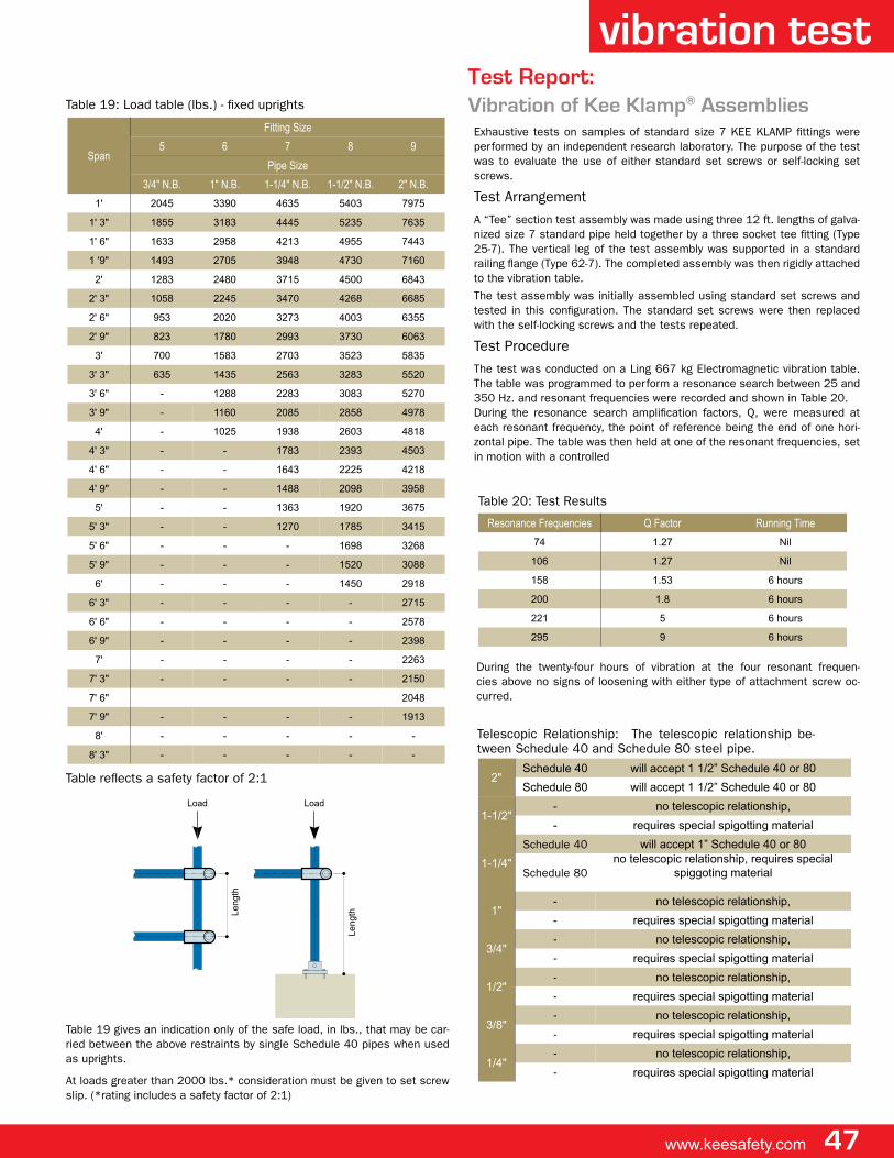
www.keesafety.com 47
table 19: load table (lbs.) - fixed uprights
Resonance Frequencies Q Factor Running Time
74 1.27 Nil
106 1.27 Nil
158 1.53 6 hours
200 1.8 6 hours
221 5 6 hours
295 9 6 hours
table 20: test results
exhaustive tests on samples of standard size 7 Kee Klamp fittings were performed by an independent research laboratory. the purpose of the test was to evaluate the use of either standard set screws or self-locking set screws.
test arrangement
a “tee” section test assembly was made using three 12 ft. lengths of galva-nized size 7 standard pipe held together by a three socket tee fitting (type 25-7). the vertical leg of the test assembly was supported in a standard railing flange (type 62-7). the completed assembly was then rigidly attached to the vibration table.
the test assembly was initially assembled using standard set screws and tested in this configuration. the standard set screws were then replaced with the self-locking screws and the tests repeated.
test procedure
the test was conducted on a ling 667 kg electromagnetic vibration table. the table was programmed to perform a resonance search between 25 and 350 hz. and resonant frequencies were recorded and shown in table 20.during the resonance search amplification factors, Q, were measured at each resonant frequency, the point of reference being the end of one hori-zontal pipe. the table was then held at one of the resonant frequencies, set in motion with a controlled
Span
Fitting Size
5 6 7 8 9
Pipe Size
3/4" N.B. 1" N.B. 1-1/4" N.B. 1-1/2" N.B. 2" N.B.
1' 2045 3390 4635 5403 7975
1' 3" 1855 3183 4445 5235 7635
1' 6" 1633 2958 4213 4955 7443
1 '9" 1493 2705 3948 4730 7160
2' 1283 2480 3715 4500 6843
2' 3" 1058 2245 3470 4268 6685
2' 6" 953 2020 3273 4003 6355
2' 9" 823 1780 2993 3730 6063
3' 700 1583 2703 3523 5835
3' 3" 635 1435 2563 3283 5520
3' 6" - 1288 2283 3083 5270
3' 9" - 1160 2085 2858 4978
4' - 1025 1938 2603 4818
4' 3" - - 1783 2393 4503
4' 6" - - 1643 2225 4218
4' 9" - - 1488 2098 3958
5' - - 1363 1920 3675
5' 3" - - 1270 1785 3415
5' 6" - - - 1698 3268
5' 9" - - - 1520 3088
6' - - - 1450 2918
6' 3" - - - - 2715
6' 6" - - - - 2578
6' 9" - - - - 2398
7' - - - - 2263
7' 3" - - - - 2150
7' 6" 2048
7' 9" - - - - 1913
8' - - - - -
8' 3" - - - - -
Length
Length Length
Load Load Load
table 19 gives an indication only of the safe load, in lbs., that may be car-ried between the above restraints by single schedule 40 pipes when used as uprights.
at loads greater than 2000 lbs.* consideration must be given to set screw slip. (*rating includes a safety factor of 2:1)
table reflects a safety factor of 2:1
Test Report:Vibration of Kee Klamp® assemblies
vibration test
during the twenty-four hours of vibration at the four resonant frequen-cies above no signs of loosening with either type of attachment screw oc-curred.
2"Schedule 40 will accept 1 1/2” Schedule 40 or 80
Schedule 80 will accept 1 1/2” Schedule 40 or 80
1-1/2"- no telescopic relationship,
- requires special spigotting material
1-1/4"
schedule 40 will accept 1” Schedule 40 or 80
schedule 80no telescopic relationship, requires special
spiggoting material
1"- no telescopic relationship,
- requires special spigotting material
3/4"- no telescopic relationship,
- requires special spigotting material
1/2"- no telescopic relationship,
- requires special spigotting material
3/8"- no telescopic relationship,
- requires special spigotting material
1/4"- no telescopic relationship,
- requires special spigotting material
telescopic relationship: the telescopic relationship be-tween schedule 40 and schedule 80 steel pipe.
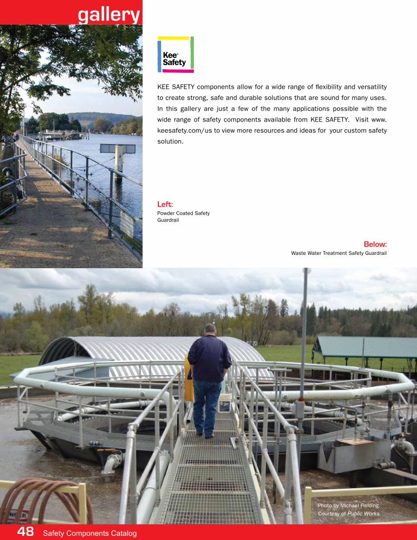
48 Safety Components Catalog
gallery
Kee safety components allow for a wide range of flexibility and versatility
to create strong, safe and durable solutions that are sound for many uses.
in this gallery are just a few of the many applications possible with the
wide range of safety components available from Kee safety. visit www.
keesafety.com/us to view more resources and ideas for your custom safety
solution.
left:powder coated safety guardrail
Below:waste water treatment safety guardrail
photo by michael fielding.
courtesy of Public Works.
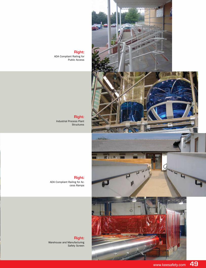
www.keesafety.com 49
Right:warehouse and manufacturing
safety screen
Right:industrial process plant
structures
Right:ada compliant railing for ac-
cess ramps
Right:ada compliant railing for
public access
50 Safety Components Catalog
fax inquiry
Fax your Technical Request to Kee SaFeTy in the USa at (716) 896-5695, or in Canada at (905) 669-4347 please check the following boxes as needed: o catalog request o technical advice o Quotationthe Kee proJects division provides the customer with the best possible service from product specification through purchase and delivery to installation advice. (* indicates required field.)
company name ___________________________________________________________________________________________________________
your name* __________________________________________________________ position ____________________________________________
street address ____________________________________________________________________________________________________________
city ________________________________________________________ state/prov ______ Zip/postal code ____________________________
telephone* _____________________________________________ ext. _________ fax ______________________________________________
email address* _______________________________________________ website __________________________________________________
please supply as much information as possible so we can properly process your request.
finish: o steel o stainless steel oaluminum opowder coated
size: o 6 (1") o 7 (1-1/4") o8 (1-1/2") o9 (2")
for railing: o inline o offset
number of horizontal rails: o 2 o 3 oother (please specify) :___________________________________________
ada: o yes o no
anti-slip required: o yes o no railing grip tape required: o yes o no
approximate length of run: ___________ft.
Use the space below to provide additional information or a sketch of your application. you can add any additional data sheets that may be useful. Number of pages faxed _________
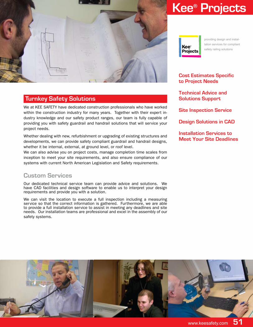
Cost estimates Specific to project Needs
Technical advice and Solutions Support
Site Inspection Service
Design Solutions in CaD
Installation Services to meet your Site Deadlines
providing design and instal-
lation services for compliant
safety railing solutions
we at Kee safety have dedicated construction professionals who have worked within the construction industry for many years. together with their expert in-dustry knowledge and our safety product ranges, our team is fully capable of providing you with safety guardrail and handrail solutions that will service your project needs.
whether dealing with new, refurbishment or upgrading of existing structures and developments, we can provide safety compliant guardrail and handrail designs, whether it be internal, external, at ground level, or roof level.we can also advise you on project costs, manage completion time scales from inception to meet your site requirements, and also ensure compliance of our systems with current north american legislation and safety requirements.
Custom Servicesour dedicated technical service team can provide advice and solutions. we have cad facilities and design software to enable us to interpret your design requirements and provide you with a solution.
we can visit the location to execute a full inspection including a measuring service so that the correct information is gathered. furthermore, we are able to provide a full installation service to assist in meeting any deadlines and site needs. our installation teams are professional and excel in the assembly of our safety systems.
Turnkey Safety Solutions
Kee® projects
www.keesafety.com 51
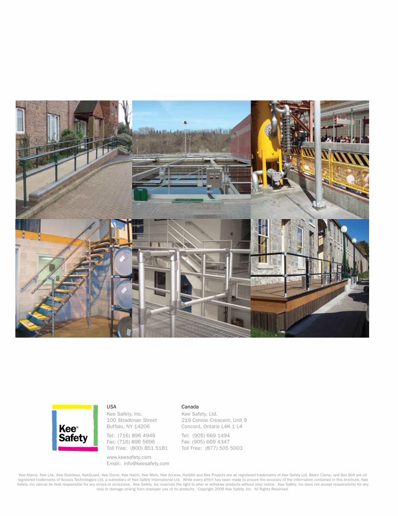
usaKee safety, inc.100 stradtman streetBuffalo, ny 14206
tel: (716) 896 4949fax: (716) 896 5696toll free: (800) 851 5181
www.keesafety.comemail: [email protected]
canadaKee safety, ltd.219 connie crescent, unit 9concord, ontario l4K 1 l4
tel: (905) 669 1494fax: (905) 669 4347toll free: (877) 505 5003
Kee Klamp, Kee lite, Kee stainless, Keeguard, Kee dome, Kee hatch, Kee mark, Kee access, KwikKit and Kee projects are all registered trademarks of Kee safety ltd, Beam clamp, and Box Bolt are all registered trademarks of access technologies ltd, a subsidiary of Kee safety international ltd. while every effort has been made to ensure the accuracy of the information contained in this brochure, Kee safety, inc cannot be held responsible for any errors or omissions. Kee safety, inc reserves the right to alter or withdraw products without prior notice. Kee safety, inc does not accept responsibility for any
loss or damage arising from improper use of its products. copyright 2008 Kee safety, inc. all rights reserved.