Embed Size (px)
Citation preview

ABB Jokab Safety Varlabergsvägen 11, SE-434 39 Kungsbacka, Sweden
www.abb.com/jokabsafety
Original instructions
Safety Contact Edges GE-Series, GP-Series

2TLC172229M0201 rev. B 2 www.abb.com/jokabsafety
2015-04-01
Read and understand this document
Please read and understand this document before using the products. Please consult your ABB JOKAB SAFETY
representative if you have any questions or comments.
WARRANTY
ABB JOKAB SAFETY’s exclusive warranty is that the products are free from defects in materials and workmanship for a period of one year (or other period if specified) from date of sale by ABB JOKAB SAFETY.
ABB JOKAB SAFETY MAKES NO WARRANTY OR REPRESENTATION, EXPRESSED OR IMPLIED, REGARDING NON-INFRINGEMENT, MERCHANTABILITY, OR FITNESS FOR PARTICULAR PURPOSE OF THE PRODUCTS, ANY BUYER OR USER ACKNOWLEDGES THAT THE BUYER OR USER ALONE HAS DETERMINED THAT THE PRODUCTS WILL SUITABLY MEET THE REQUIREMENTS OR THEIR INTENDED USE. ABB JOKAB SAFETY DISCLAIMS ALL OTHER WARRANTIES, EXPRESSED OR IMPLIED.
LIMITATIONS OF LIABILITY
ABB JOKAB SAFETY SHALL NOT BE RESPONSIBLE FOR SPECIAL, INDIRECT, OR CONSEQUENTIAL DAMAGES, LOSS OF PROFITS OR COMMERCIAL LOSS IN ANY WAY CONNECTED WITH THE PRODUCTS, WHETHER SUCH CLAIM IS BASED ON CONTRACT, WARRANTY, NEGLIGENCE, OR STRICT LIABILITY.
In no event shall responsibility of ABB JOKAB SAFETY for any act exceed the individual price of the product on which liability asserted.
IN NO EVENT SHALL JOKAB SAFETY BE RESPONSIBLE FOR WARRANTY, REPAIR, OR OTHER CLAIMS REGARDING THE PRODUCTS UNLESS JOKAB SAFETY’S ANALYSIS CONFIRMS THAT THE PRODUCTS WERE PROPERLY HANDLED, STORED, INSTALLED, AND MAINTAINED AND NOT SUBJECT TO ABUSE, MISUSE, OR INAPPROPRIATE MODIFICATION OR REPAIR.
SUITABILITY FOR USE
ABB JOKAB SAFETY shall not be responsible for conformity with any standards, codes, or regulations that apply to the combination of products in the customer’s application or use of the product. At the customer’s request, ABB JOKAB SAFETY will provide applicable third party certification documents identifying ratings and limitations of use that apply to the products. This information by itself is not sufficient for a complete determination of the suitability of the products in combination with the end product, machine, system, or other application or use.
The following are some examples of applications for which particular attention must be given. This is not intended to be an exhaustive list of all possible uses of the products, nor is it intended to imply that the uses listed may be suitable for the products:
Outdoor use, uses involving potential chemical contamination or electrical interference, or conditions or uses not described in this document.
Nuclear energy control systems, combustion systems, railroad systems, aviation systems, medical equipment, amusement machines, vehicles, and installations subject to separate industry or government regulations.
Systems, machines, and equipment that could present a risk to life or property.
Please know and observe all prohibitions of use applicable to the products.
NEVER USE THE PRODUCTS FOR AN APPLICATION INVOLVING SERIOUS RISK TO LIFE OR PROPERTY WITHOUT ENSURING THAT THE SYSTEM AS A WHOLE HAS BEEN DESIGNED TO ADDRESS THE RISKS, AND THAT THE JOKAB SAFETY PRODUCT IS PROPERLY RATED AND INSTALLED FOR THE INTENDED USE WITHIN THE OVERALL EQUIPMENT OR SYSTEM.
PERFORMANCE DATA
While every effort has been taken to ensure the accuracy of the information contained in this manual ABB JOKAB SAFETY cannot accept responsibility for errors or omissions and reserves the right to make changes and improvements without notice. Performance data given in this document is provided as a guide for the user in determining suitability and does not constitute a warranty. It may represent the result of JOKAB SAFETY’S test conditions, and the users must correlate it to actual application requirements. Actual performance is subject to the ABB JOKAB SAFETY Warranty and Limitations of Liability.

2TLC172229M0201 rev. B 3 www.abb.com/jokabsafety
2015-04-01
Table of Contents
1 Introduction ......................................................................................................................................... 4
Scope ............................................................................................................................................................................ 4
Audience ....................................................................................................................................................................... 4
Prerequisites ................................................................................................................................................................. 4
Special notes ................................................................................................................................................................. 4
2 Overview .............................................................................................................................................. 5
General description ....................................................................................................................................................... 5
Safety regulations ......................................................................................................................................................... 5
3 Installation and maintenance .............................................................................................................. 6
Contact Edge GE – General ......................................................................................................................................... 6
Assembly Instructions for the GE-series ....................................................................................................................... 6
Contact Edge GP – General ....................................................................................................................................... 13
Safety contact edge, construction ............................................................................................................................... 13
Safety contact strip SKS 18 ........................................................................................................................................ 13
Contact Edge GP – Installation ................................................................................................................................... 14
4 Connections ....................................................................................................................................... 16
Installation precautions ............................................................................................................................................... 18
Maintenance ................................................................................................................................................................ 18
5 Model overview .................................................................................................................................. 19
6 Technical data ................................................................................................................................... 21
7 EC Declaration of conformity ........................................................................................................... 25

2TLC172229M0201 rev. B 4 www.abb.com/jokabsafety
2015-04-01
1 Introduction
Scope
The purpose of these instructions is to describe the safety contact edges and to provide the necessary information
required for installation and use.
Audience
This document is intended for authorized installation personnel.
Prerequisites
It is assumed that the reader of this document has knowledge of the following:
Basic knowledge of ABB Jokab Safety products.
Knowledge of machine safety.
Special notes
Pay attention to the following special notes in the document:
Warning!
Danger of severe personal injury!
An instruction or procedure which, if not carried out correctly, may result in injury to the technician or other personnel.
Caution! Danger of damage to the equipment!
An instruction or procedure which, if not carried out correctly, may damage the equipment.
NB: Notes are used to provide important or explanatory information.

2TLC172229M0201 rev. B 5 www.abb.com/jokabsafety
2015-04-01
2 Overview
General description
Contact edges are used as protection against crushing injuries for example, moving machine parts or automatic doors.
This manual describes Contact edges with cast-in contact strips (GE) and Contact edges with contact strips SKS 18
(GP).
The contact edges GE consist of a rubber profile with a cast-in contact strip. They are made up simply using
connection plugs that are glued to the ends together with a terminal cap. The rubber profile is fitted on an aluminium
profile. The rubber profile is available in EPDM design.
The contact edges GP consist of a rubber profile with a safety contact strip, SKS 18, inside. The contact edge is fitted
on an aluminium profile. The rubber profile is available in EPDM or NBR.
Safety regulations
Warning!
Carefully read through this entire manual before using the device.
The devices shall be installed by a trained electrician following the Safety regulations, standards and the Machine
directive.
Failure to comply with instructions, operation that is not in accordance with the use prescribed in these instructions,
improper installation or handling of the device can affect the safety of people and the plant.
For installation and prescribed use of the product, the special notes in the instructions must be carefully observed and
the technical standards relevant to the application must be considered.
In case of failure to comply with the instructions or standards, especially when tampering with and/or modifying the
product, any liability is excluded.

2TLC172229M0201 rev. B 6 www.abb.com/jokabsafety
2015-04-01
3 Installation and maintenance
Contact Edge GE – General
Inside the contact edge there is a cast-in contact strip that consist of two conductive alternating surfaces on the inside
and a highly-effective insulation shell. There are two conductive wires in the contact surfaces that allow for low ohm
measurements even when the contact edge has an extended length. The cast-in contact strip is protected against
damage by the surrounding chamber. The cast end plugs ensure a permanent contact from the conductive surfaces in
the contact strip. A special flexible adhesive is used to make the connector ring watertight. Because of the contact
points, the safety contact edge has approximate 20 mm of inactive length at each end. Assembly of the contact edge
GE can be made by the customer or chosen to be manufactured by the ABB Jokab Safety factory.
Assembly Instructions for the GE-series
1. Cutting the safety-contact-edge
The contact edge is to be cut to correct length (cut measure). It is to be noted that the planes of section are
right-angled and smooth. The measure should be 25 mm shorter than the final dimension of the finished
contact edge (height of end caps). (A = Cut measure, B= Final measure)
1. Terminal cap 2. Rubber profile with integrated contact strip 3. Terminal resistor (Can be connection plug with
cable as well) 4. Connection plug 5. Aluminium profile
2TLC172229M0201 rev. B 7 www.abb.com/jokabsafety
2015-04-01
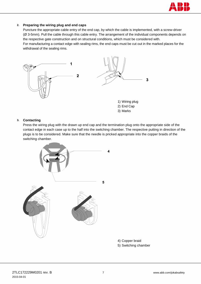
2. Preparing the wiring plug and end caps
Puncture the appropriate cable entry of the end cap, by which the cable is implemented, with a screw-driver
(Ø 3-5mm). Pull the cable through this cable entry. The arrangement of the individual components depends on
the respective gate construction and on structural conditions, which must be considered with.
For manufacturing a contact edge with sealing rims, the end caps must be cut out in the marked places for the
withdrawal of the sealing rims.
1) Wiring plug
2) End Cap
3) Marks
3. Contacting
Press the wiring plug with the drawn up end cap and the termination plug onto the appropriate side of the
contact edge in each case up to the half into the switching chamber. The respective putting in direction of the
plugs is to be considered. Make sure that the needle is pricked appropriate into the copper braids of the
switching chamber.
4) Copper braid
5) Switching chamber

2TLC172229M0201 rev. B 8 www.abb.com/jokabsafety
2015-04-01
4. Testing
Measure the plugger together with the contact edge with a commercial resistance measuring instrument. The resistance between blue-blue (out form each end) or brown-brown wire is to be as low as possible, not
exceeding 10 ohms. With no load on the safety edge, resistance between blue-brown wires (both
combinations) is to be as high as possible, not below 10.000 ohms. With loaded edge, the resistance should
be between 10–50 ohms.
The resistance will vary with pressure applied and distance from ends. Close to the ends, it may be possible to
achieve “contact” at a high force but this should not be considered as safe operation. Normally there will be a
”dead zone” approximately 20–30 mm from each end.
If the resistance values should not be correct, the wiring plugs must be removed and pressed in again.
5. Gluing the wall plugs
The ambient temperature during glueing should be between 10° and 30°C and the relative humidity between
40 and 70%. Coat the surfaces of the wiring plugs and the switching chamber which will be stuck together with
the CA-Primer. Provide the wiring plug all around with glue „Contact VA 250 black“. Immediately after that,
press the plug strongly into the switching chamber (if available by using the auxiliary tool). The steps are to be
repeated for the termination plug or connection plug in the other end.
6) Primer
7) Glue
8) Auxiliary tool

2TLC172229M0201 rev. B 9 www.abb.com/jokabsafety
2015-04-01
6. Gluing the end caps
Coat the surfaces of the contact edge and the end cap which will be stuck together with the CA-Primer. For an
accelerated adhesion the surfaces of the end cap can be coated additionally with an activator. Provide the front
surface and the circulating outline surface of the contact edge with glue „Contact VA 250 black“. Turn the end
cap over the contact edge and immediately press the cap evenly (Keep pressed, until the glue works). The
steps are to be repeated for the second cap.
9) Primer
10) Activator
11) Glue
7. Measuring the contact edge
Measure the finished manufactured contact edge as described under point 4.
8. Water drain
For a long life span of a vertical installed contact edge it is important to provide a water drain. For this the marked
lower water outlet is to be cut out. When horizontal assembling both openings should be cut out. Use a knife to
cut out the holes but wait until the glue has hardened enough (2–3 h).

2TLC172229M0201 rev. B 10 www.abb.com/jokabsafety
2015-04-01
Assembly instructions for GE-series
1. To facilitate installation of the safety contact edge, the aluminium C-profile may only be attached to even surfaces. If the safety contact edge is mounted in a bend, the radius must not be less than the specified minimum.
2. The aluminium C-profile must be fitted with countersunk screws or rivets. A diameter of 4 mm is sufficient. The holes of 4.5 mm must be evenly distributed over the entire length of the C-profile with distances between them not exceeding 300 mm. They have to be countersunk according to the screw size.
3. Pan- or round-head screws should not be used. Otherwise the connecting wire in the aluminum C-profile could be damaged.

2TLC172229M0201 rev. B 11 www.abb.com/jokabsafety
2015-04-01
4. In order to lead the connecting wire through the C-profile, an 8 mm hole has to be drilled in the
appropriate place. Carefully remove the burr from both sides.
5. The connecting wire and the 30 cm cable end with the integrated terminal resistor can be placed in the aluminium C-profile.
6. In order to make fitting the safety contact edge easier, the aluminium C-profile and the safety contact edge should be sprayed with soapy water. Once the soap suds have evaporated the contact edge is firmly fitted in the C-profile. NB! To prevent a subsequent slipping of the safety contact edge talcum powder, oils or similarly durable lubricants may not be used!

2TLC172229M0201 rev. B 12 www.abb.com/jokabsafety
2015-04-01
7. Safety contact edges with a c-base have to be clipsed with one side into the C-profile. Then press in
the complete C-base. Pulling or pushing the safety contact edge into the aluminium C-profile can cause damage to the contact edge and should be avoided at all costs.
8. Safety contact edges with a T-base have to be pushed into the aluminium C-profile.
NB! Any other methods of fastenings are only permitted on prior agreement with the manufacturer!

2TLC172229M0201 rev. B 13 www.abb.com/jokabsafety
2015-04-01
Contact Edge GP – General The safety contact strip, SKS 18, the actual contactor, is located inside the safety contact edge. The safety contact
strip consist of a homogeneous highly insulating outer EPDM material and has two internal conducting contact
surfaces. The conducting elastomer contains two copper wires that provide low-resistance detection even in lengths
exceeding 100 meters (NB! The contact edge GP series is only possible to make in max 6 meter length). Because of
the contact points, the safety contact edge has approximate 30 mm of inactive length at each end. To provide
protection against damage and to enable its proper use, the safety contact strip is inserted into the switching chamber
of the rubber contactor profile. The rubber profiles (EDPM or NBR) are then permanently sealed with a special elastic
adhesive and end caps to make them watertight. The safety contact edge is then pressed into the aluminium profile.
Assembly of the contact edge GP is always made by the ABB Jokab Safety factory.
Safety contact edge, construction
1) Rubber profile 2) SKS 18 3) Aluminium support profile, C-profile
Safety contact strip SKS 18
4) Conductive contact surface 5) Highly insulated outer material 6) Copper wire

2TLC172229M0201 rev. B 14 www.abb.com/jokabsafety
2015-04-01
Contact Edge GP – Installation
1. To facilitate installation of the safety contact edge, the aluminium C-profile may only be attached to even surfaces. If the safety contact edge is mounted in a bend, the radius must not be less than the specified minimum.
2. The aluminium C-profile must be fitted with countersunk screws or rivets. A diameter of 4 mm is sufficient. The holes of 4.5 mm must be evenly distributed over the entire length of the C-profile with distances between them not exceeding 300 mm. They have to be countersunk according to the screw size.
3. Pan- or round-head screws should not be used. Otherwise the connecting wire in the aluminum C-profile could be damaged.

2TLC172229M0201 rev. B 15 www.abb.com/jokabsafety
2015-04-01
4. In order to lead the connecting wire through the C-profile, an 8 mm hole has to be drilled in the
appropriate place. Carefully remove the burr from both sides.
5. The connecting wire and the 30 cm cable end with the integrated terminal resistor can be placed in the aluminium C-profile.
6. In order to make fitting the safety contact edge easier, the aluminium C-profile and the safety contact edge should be sprayed with soapy water. Once the soap suds have evaporated the contact edge is firmly fitted in the C-profile. NB! To prevent a subsequent slipping of the safety contact edge talcum powder, oils or similarly durable lubricants may not be used!
NB! Pulling or pushing the safety contact edge into the aluminium profile can cause damage to the contact edge and should be avoided at all costs. Any other proposed methods of adaptation should only be attempted after consultation with ABB Jokab Safety. Other methods of adaptation, unless approved by ABB Jokab Safety, may invalidate the warranty and may lead to incorrect device operation.

2TLC172229M0201 rev. B 16 www.abb.com/jokabsafety
2015-04-01
4 Connections
Contact edges must be connected to a suitable safety evaluation unit (e.g. ABB Jokab Safey safety relays RT6, RT7A/B, RT9, Vital with Tina 6A or Pluto safety-PLC). The safety evaluation unit monitors the functionality of the contact protection and detects any breaks or short-circuits in the lines. Several crush protection units can be connected in series while still retaining the same level of safety. When pressure is applied, the active surface of the contact area in the contact protection is closed and the safety output on the monitoring unit trips. A stop signal will be sent to the machine’s safety circuits preventing any dangerous movements. NB! If alternative units are used rather than the recommended ABB Jokab Safety relays, it is essential that the user checks their suitability before use. Failure to do so may result in incorrect operation and/or damage to the equipment and invalidate warranty.
Connection contact protection for safety relay RT6

2TLC172229M0201 rev. B 17 www.abb.com/jokabsafety
2015-04-01
Connection contact protection for safety controller Vital 1
Connection contact protection for safety PLC Pluto

2TLC172229M0201 rev. B 18 www.abb.com/jokabsafety
2015-04-01
Installation precautions
Warning! All the safety functions must be tested before starting up the system.
Maintenance
Warning! The safety functions and the mechanics shall be tested regularly.
Warning! In case of breakdown or damage to the product, contact the nearest ABB Jokab Safety Service Office or
reseller. Do not try to repair the product yourself since it may accidentally cause permanent damage to the product,
impairing the safety of the device which in turn could lead to serious injury to personnel.
Caution! ABB Jokab Safety will not accept responsibility for failure of the switch functions if the installation and
maintenance requirements shown in this sheet are not implemented. These requirements form part of the product
warranty.

2TLC172229M0201 rev. B 19 www.abb.com/jokabsafety
2015-04-01
5 Model overview
GE Contact edge
Ordering Contact Edge GE
When ordering a Contact Edge GE it's necessary to order every part specifically. Type of contact edge(in meter), aluminium profile(in meter), connection plugs(one for each end) and end caps(one for each end). If manufactured by ABB Jokab Safety another article need to be added. Always specify length of safety edge.Accessories for GE is ordered separately.
Article number Description
GE – Contact edge
2TLA076005R0200 Contact edge GE 25-25 EPDM, per metre
2TLA076005R0400 Contact edge GE 25-45 EPDM, per metre
Accessories/Cables
Article number Type
2TLA076002R0200 Al 25-14 aluminium profile
2TLA076005R4400 Connection plug with 2,5 m cable
2TLA076005R4500 Connection plug with 5 m cable
2TLA076005R4600 Connection plug with 10 m cable
2TLA076005R4700 Connection plug with resistor 8,2 Ω
2TLA076005R6100 End cap for GE25-45
2TLA076005R6200 End cap for GE25-25
2TLA076005R7600 Glueing set small 5 gr/5ml
2TLA076005R7700 Glueing set large 20 gr/10ml
2TLA076005R8500 Scissor
2TLA076005R8600 Plug insert tool
2TLA076008R0000 Production cost if GE contact edge assembled by ABB Jokab Safety
GE 25-25 (GE 225 TK) GE 25-40 (GE 245 TK)
NB! Measurements are in mm.
2TLC172229M0201 rev. B 20 www.abb.com/jokabsafety
2015-04-01
GP Contact edge
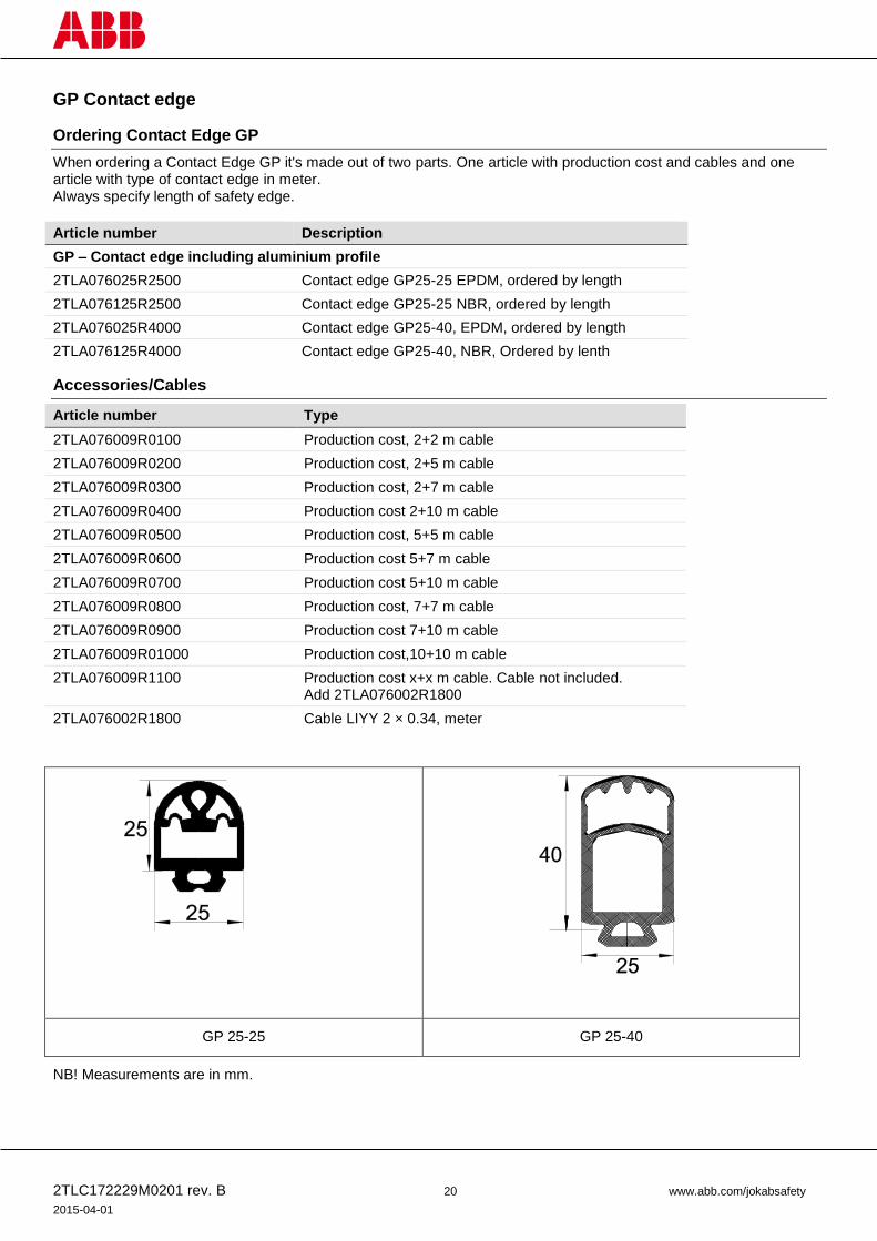
Ordering Contact Edge GP
When ordering a Contact Edge GP it's made out of two parts. One article with production cost and cables and one article with type of contact edge in meter. Always specify length of safety edge.
Article number Description
GP – Contact edge including aluminium profile
2TLA076025R2500 Contact edge GP25-25 EPDM, ordered by length
2TLA076125R2500 Contact edge GP25-25 NBR, ordered by length
2TLA076025R4000 Contact edge GP25-40, EPDM, ordered by length
2TLA076125R4000 Contact edge GP25-40, NBR, Ordered by lenth
Accessories/Cables
Article number Type
2TLA076009R0100 Production cost, 2+2 m cable
2TLA076009R0200 Production cost, 2+5 m cable
2TLA076009R0300 Production cost, 2+7 m cable
2TLA076009R0400 Production cost 2+10 m cable
2TLA076009R0500 Production cost, 5+5 m cable
2TLA076009R0600 Production cost 5+7 m cable
2TLA076009R0700 Production cost 5+10 m cable
2TLA076009R0800 Production cost, 7+7 m cable
2TLA076009R0900 Production cost 7+10 m cable
2TLA076009R01000 Production cost,10+10 m cable
2TLA076009R1100 Production cost x+x m cable. Cable not included. Add 2TLA076002R1800
2TLA076002R1800 Cable LIYY 2 × 0.34, meter
GP 25-25 GP 25-40
NB! Measurements are in mm.
2TLC172229M0201 rev. B 21 www.abb.com/jokabsafety
2015-04-01
6 Technical data
Manufacturer
Address ABB JOKAB SAFETY
Varlabergsvägen 11 S-434 91 Kungsbacka Sweden
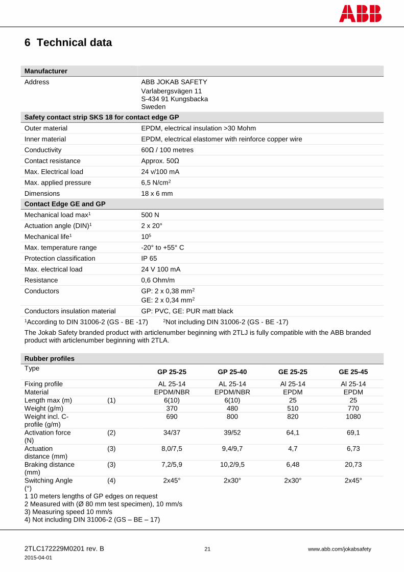
Safety contact strip SKS 18 for contact edge GP
Outer material EPDM, electrical insulation >30 Mohm
Inner material EPDM, electrical elastomer with reinforce copper wire
Conductivity 60Ω / 100 metres
Contact resistance Approx. 50Ω
Max. Electrical load 24 v/100 mA
Max. applied pressure 6,5 N/cm2
Dimensions 18 x 6 mm
Contact Edge GE and GP
Mechanical load max1 500 N
Actuation angle (DIN)1 2 x 20°
Mechanical life1 105
Max. temperature range -20° to +55° C
Protection classification IP 65
Max. electrical load 24 V 100 mA
Resistance 0,6 Ohm/m
Conductors GP: 2 x 0,38 mm2
GE: 2 x 0,34 mm2
Conductors insulation material GP: PVC, GE: PUR matt black
1According to DIN 31006-2 (GS - BE -17) 2Not including DIN 31006-2 (GS - BE -17)
The Jokab Safety branded product with articlenumber beginning with 2TLJ is fully compatible with the ABB branded product with articlenumber beginning with 2TLA.
Rubber profiles
Type GP 25-25 GP 25-40 GE 25-25 GE 25-45
Fixing profile AL 25-14 AL 25-14 Al 25-14 Al 25-14
Material EPDM/NBR EPDM/NBR EPDM EPDM
Length max (m) (1) 6(10) 6(10) 25 25
Weight (g/m) 370 480 510 770
Weight incl. C-profile (g/m)
690 800 820 1080
Activation force (N)
(2) 34/37 39/52 64,1 69,1
Actuation distance (mm)
(3) 8,0/7,5 9,4/9,7 4,7 6,73
Braking distance (mm)
(3) 7,2/5,9 10,2/9,5 6,48 20,73
Switching Angle (°)
(4) 2x45° 2x30° 2x30° 2x45°
1 10 meters lengths of GP edges on request 2 Measured with (Ø 80 mm test specimen), 10 mm/s 3) Measuring speed 10 mm/s 4) Not including DIN 31006-2 (GS – BE – 17)
2TLC172229M0201 rev. B 22 www.abb.com/jokabsafety
2015-04-01
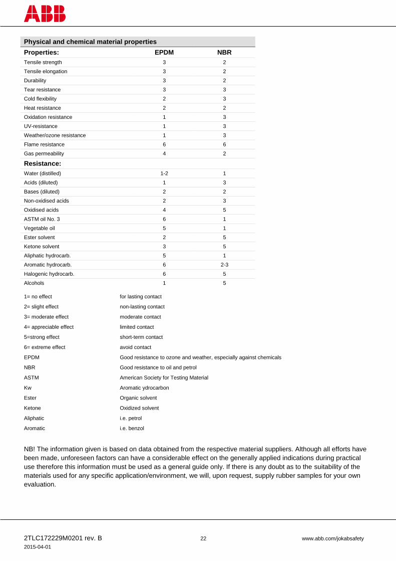
Physical and chemical material properties
Properties: EPDM NBR
Tensile strength 3 2
Tensile elongation 3 2
Durability 3 2
Tear resistance 3 3
Cold flexibility 2 3
Heat resistance 2 2
Oxidation resistance 1 3
UV-resistance 1 3
Weather/ozone resistance 1 3
Flame resistance 6 6
Gas permeability 4 2
Resistance:
Water (distilled) 1-2 1
Acids (diluted) 1 3
Bases (diluted) 2 2
Non-oxidised acids 2 3
Oxidised acids 4 5
ASTM oil No. 3 6 1
Vegetable oil 5 1
Ester solvent 2 5
Ketone solvent 3 5
Aliphatic hydrocarb. 5 1
Aromatic hydrocarb. 6 2-3
Halogenic hydrocarb. 6 5
Alcohols 1 5
1= no effect for lasting contact
2= slight effect non-lasting contact
3= moderate effect moderate contact
4= appreciable effect limited contact
5=strong effect short-term contact
6= extreme effect avoid contact
EPDM Good resistance to ozone and weather, especially against chemicals
NBR Good resistance to oil and petrol
ASTM American Society for Testing Material
Kw Aromatic ydrocarbon
Ester Organic solvent
Ketone Oxidized solvent
Aliphatic i.e. petrol
Aromatic i.e. benzol
NB! The information given is based on data obtained from the respective material suppliers. Although all efforts have
been made, unforeseen factors can have a considerable effect on the generally applied indications during practical
use therefore this information must be used as a general guide only. If there is any doubt as to the suitability of the
materials used for any specific application/environment, we will, upon request, supply rubber samples for your own
evaluation.

2TLC172229M0201 rev. B 23 www.abb.com/jokabsafety
2015-04-01
GE – Bending angles and radii The aluminum C-profile has to be prepared at the factory if it has to be bent.
GE – Bending angles for different assembly arrangements
Type A B C
GP 25-25 (GE 225 TK) 45° 20° 30°
GP 25-40 (GE 245 TK) 45° 10° 20°
GE – Bending radii for different assembly arrangements
Type Figure 2 Figure 3 Figure 4
GP 25-25 (GE 225 TK) 300 400 200
GP 25-40 (GE 245 TK) 400 500 200
Figure 1
Figure 2
Figure 3
Figure 4
1. Side view 2. Top view 3. Alu C-profile
2TLC172229M0201 rev. B 24 www.abb.com/jokabsafety
2015-04-01
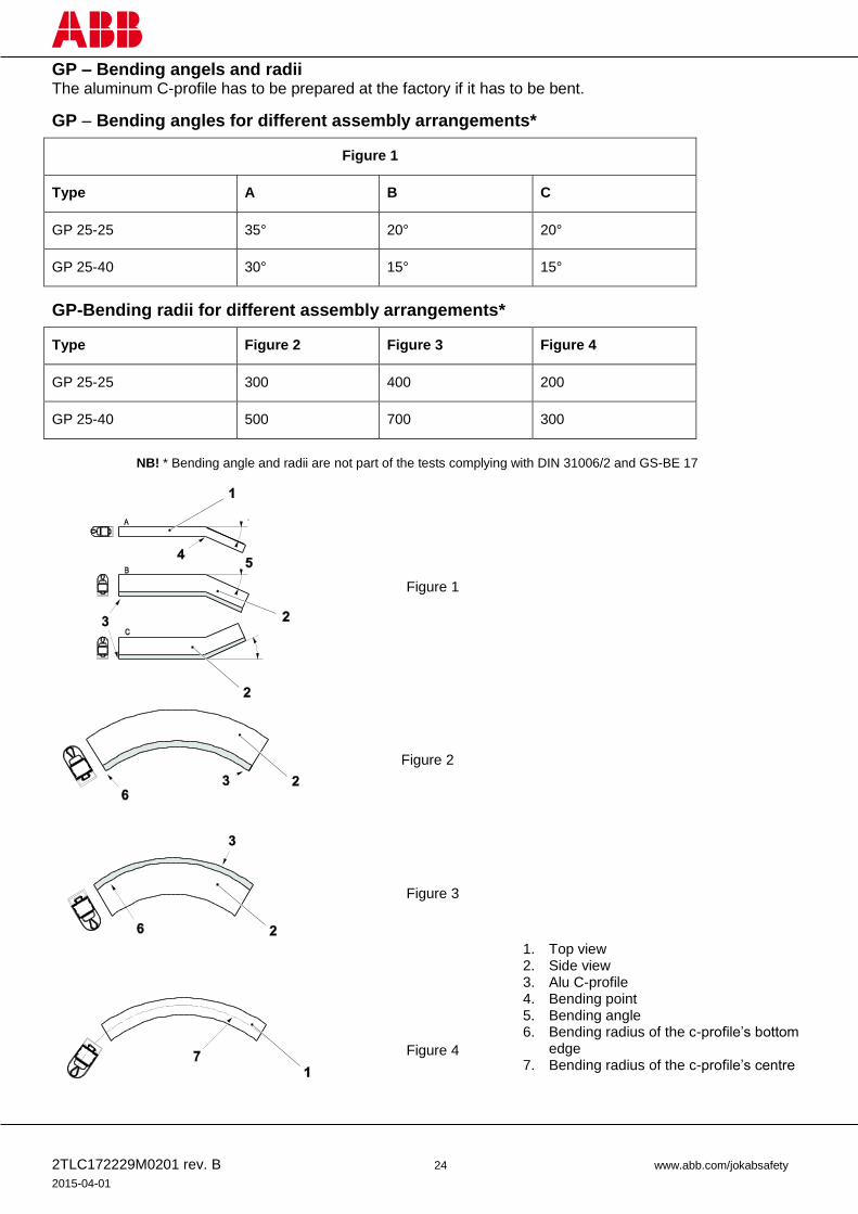
GP – Bending angels and radii The aluminum C-profile has to be prepared at the factory if it has to be bent.
GP – Bending angles for different assembly arrangements*
Figure 1
Type A B C
GP 25-25 35° 20° 20°
GP 25-40 30° 15° 15°
GP-Bending radii for different assembly arrangements*
Type Figure 2 Figure 3 Figure 4
GP 25-25 300 400 200
GP 25-40 500 700 300
Figure 1
Figure 2
Figure 3
Figure 4
1. Top view 2. Side view 3. Alu C-profile 4. Bending point 5. Bending angle 6. Bending radius of the c-profile’s bottom
edge 7. Bending radius of the c-profile’s centre
NB! * Bending angle and radii are not part of the tests complying with DIN 31006/2 and GS-BE 17

2TLC172229M0201 rev. B 25 www.abb.com/jokabsafety
2015-04-01
7 EC Declaration of conformity

2TLC172229M0201 rev. B 26 www.abb.com/jokabsafety
2015-04-01