Embed Size (px)
Citation preview
SIMATIC Safety Engineering in SIMATIC S7
________________________________________________________________________________________________________________
Preface
Overview of Fail-safe Systems
1Configurations and Help with Selection
2
Communication Options 3
Safety in F-Systems 4
Achievable Safety Classes with F-I/O
5
Configuring F-Systems 6
Programming F-Systems 7
Monitoring and Response Times of F-Systems
A
SIMATIC
Safety Engineering in SIMATIC S7
System Manual
08/2005 A5E00109529-04
Safety Guidelines This manual contains notices you have to observe in order to ensure your personal safety, as well as to prevent damage to property. The notices referring to your personal safety are highlighted in the manual by a safety alert symbol, notices referring only to property damage have no safety alert symbol. These notices shown below are graded according to the degree of danger.
Danger
indicates that death or severe personal injury will result if proper precautions are not taken.
Warning
indicates that death or severe personal injury may result if proper precautions are not taken.
Caution
with a safety alert symbol, indicates that minor personal injury can result if proper precautions are not taken.
Caution
without a safety alert symbol, indicates that property damage can result if proper precautions are not taken.
Notice
indicates that an unintended result or situation can occur if the corresponding information is not taken into account.
If more than one degree of danger is present, the warning notice representing the highest degree of danger will be used. A notice warning of injury to persons with a safety alert symbol may also include a warning relating to property damage.
Qualified Personnel The device/system may only be set up and used in conjunction with this documentation. Commissioning and operation of a device/system may only be performed by qualified personnel. Within the context of the safety notes in this documentation qualified persons are defined as persons who are authorized to commission, ground and label devices, systems and circuits in accordance with established safety practices and standards.
Prescribed Usage Note the following:
Warning
This device may only be used for the applications described in the catalog or the technical description and only in connection with devices or components from other manufacturers which have been approved or recommended by Siemens. Correct, reliable operation of the product requires proper transport, storage, positioning and assembly as well as careful operation and maintenance.
Trademarks All names identified by ® are registered trademarks of the Siemens AG. The remaining trademarks in this publication may be trademarks whose use by third parties for their own purposes could violate the rights of the owner.
Disclaimer of Liability We have reviewed the contents of this publication to ensure consistency with the hardware and software described. Since variance cannot be precluded entirely, we cannot guarantee full consistency. However, the information in this publication is reviewed regularly and any necessary corrections are included in subsequent editions.
Siemens AG Automation and Drives Postfach 48 48 90437 NÜRNBERG GERMANY
Order No.: A5E00109529-04 Edition 08/2005
Copyright © Siemens AG 2005. Technical data subject to change
Safety Engineering in SIMATIC S7 System Manual, 08/2005, A5E00109529-04 iii
Preface
Purpose of System Description This system description provides an overview of the S7 Distributed Safety and S7 F/FH Systems fail-safe automation systems. It identifies the similarities and differences between S7 Distributed Safety and S7 F/FH Systems and presents detailed technical information applicable to both S7 Distributed Safety and S7 F/FH Systems.
The system description helps you to decide which fail-safe system is best suited for your automation task. It is intended as starting information for decision makers and as a source of technical information on S7 Distributed Safety and S7 F/FH Systems fail-safe automation systems for service and commissioning personnel (e.g., detailed information on monitoring and response times of S7 Distributed Safety and S7 F/FH Systems is provided in the appendix).
Scope of System Description This system description applies to the S7 Distributed Safety, S7 F Systems, and S7 FH Systems fail-safe systems.
In addition, this system description addresses integration of the following fail-safe I/O devices in S7 Distributed Safety and S7 F/FH Systems:
• S7-300 fail-safe signal modules
• ET 200S fail-safe modules
• ET 200pro fail-safe modules
• ET 200eco fail-safe I/O module
• Fail-safe DP standard slaves / I/O standard devices
Preface
Safety Engineering in SIMATIC S7 iv System Manual, 08/2005, A5E00109529-04
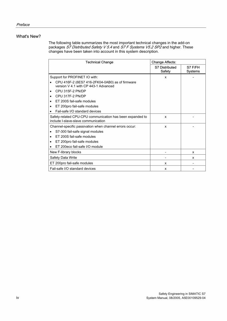
What's New? The following table summarizes the most important technical changes in the add-on packages S7 Distributed Safety V 5.4 and S7 F Systems V5.2 SP2 and higher. These changes have been taken into account in this system description.
Change Affects: Technical Change
S7 Distributed Safety
S7 F/FH Systems
Support for PROFINET IO with: • CPU 416F-2 (6ES7 416-2FK04-0AB0) as of firmware
version V 4.1 with CP 443-1 Advanced • CPU 315F-2 PN/DP • CPU 317F-2 PN/DP • ET 200S fail-safe modules • ET 200pro fail-safe modules • Fail-safe I/O standard devices
x -
Safety-related CPU-CPU communication has been expanded to include I-slave-slave communication
x -
Channel-specific passivation when channel errors occur: • S7-300 fail-safe signal modules • ET 200S fail-safe modules • ET 200pro fail-safe modules • ET 200eco fail-safe I/O module
x -
New F-library blocks - x Safety Data Write - x ET 200pro fail-safe modules x - Fail-safe I/O standard devices x -
Preface
Safety Engineering in SIMATIC S7 System Manual, 08/2005, A5E00109529-04 v
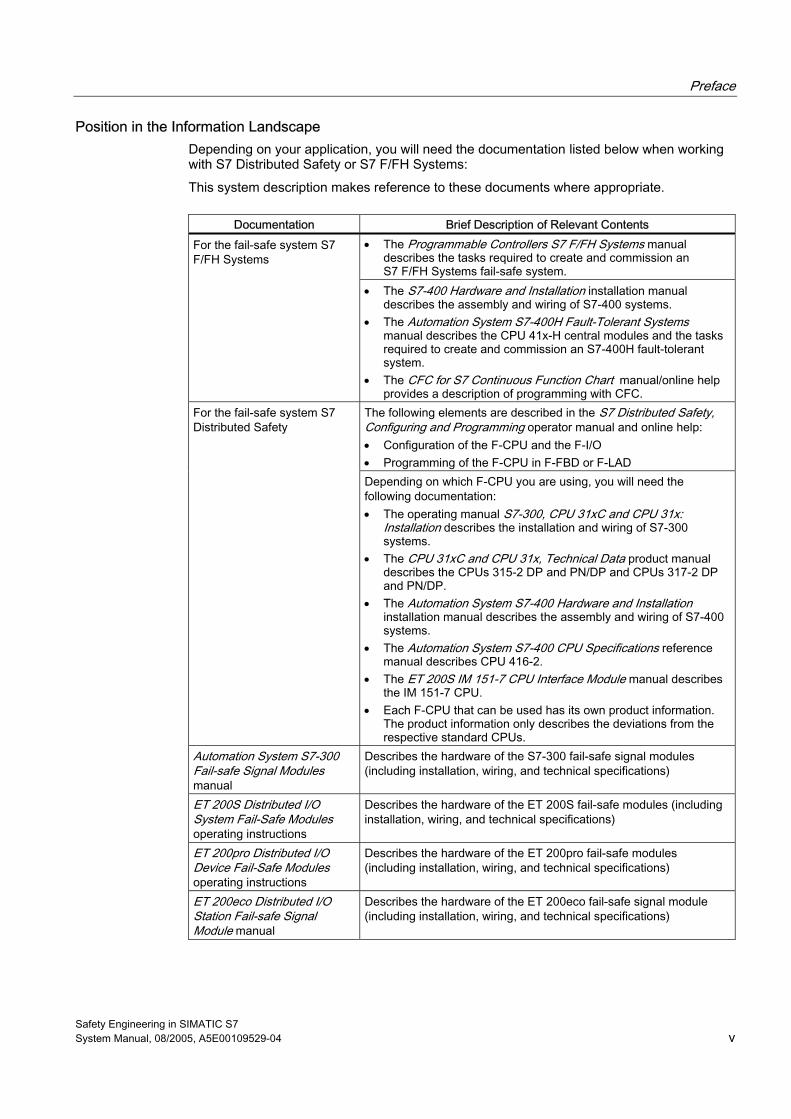
Position in the Information Landscape Depending on your application, you will need the documentation listed below when working with S7 Distributed Safety or S7 F/FH Systems:
This system description makes reference to these documents where appropriate.
Documentation Brief Description of Relevant Contents • The Programmable Controllers S7 F/FH Systems manual
describes the tasks required to create and commission an S7 F/FH Systems fail-safe system.
For the fail-safe system S7 F/FH Systems
• The S7-400 Hardware and Installation installation manual describes the assembly and wiring of S7-400 systems.
• The Automation System S7-400H Fault-Tolerant Systems manual describes the CPU 41x-H central modules and the tasks required to create and commission an S7-400H fault-tolerant system.
• The CFC for S7 Continuous Function Chart manual/online help provides a description of programming with CFC.
The following elements are described in the S7 Distributed Safety, Configuring and Programming operator manual and online help: • Configuration of the F-CPU and the F-I/O • Programming of the F-CPU in F-FBD or F-LAD
For the fail-safe system S7 Distributed Safety
Depending on which F-CPU you are using, you will need the following documentation: • The operating manual S7-300, CPU 31xC and CPU 31x:
Installation describes the installation and wiring of S7-300 systems.
• The CPU 31xC and CPU 31x, Technical Data product manual describes the CPUs 315-2 DP and PN/DP and CPUs 317-2 DP and PN/DP.
• The Automation System S7-400 Hardware and Installation installation manual describes the assembly and wiring of S7-400 systems.
• The Automation System S7-400 CPU Specifications reference manual describes CPU 416-2.
• The ET 200S IM 151-7 CPU Interface Module manual describes the IM 151-7 CPU.
• Each F-CPU that can be used has its own product information. The product information only describes the deviations from the respective standard CPUs.
Automation System S7-300 Fail-safe Signal Modules manual
Describes the hardware of the S7-300 fail-safe signal modules (including installation, wiring, and technical specifications)
ET 200S Distributed I/O System Fail-Safe Modules operating instructions
Describes the hardware of the ET 200S fail-safe modules (including installation, wiring, and technical specifications)
ET 200pro Distributed I/O Device Fail-Safe Modules operating instructions
Describes the hardware of the ET 200pro fail-safe modules (including installation, wiring, and technical specifications)
ET 200eco Distributed I/O Station Fail-safe Signal Module manual
Describes the hardware of the ET 200eco fail-safe signal module (including installation, wiring, and technical specifications)
Preface
Safety Engineering in SIMATIC S7 vi System Manual, 08/2005, A5E00109529-04
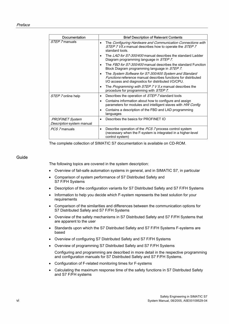
Documentation Brief Description of Relevant Contents STEP 7 manuals • The Configuring Hardware and Communication Connections with
STEP 7 V5.x manual describes how to operate the STEP 7 standard tools.
• The LAD for S7-300/400 manual describes the standard Ladder Diagram programming language in STEP 7.
• The FBD for S7-300/400 manual describes the standard Function Block Diagram programming language in STEP 7.
• The System Software for S7-300/400 System and Standard Functions reference manual describes functions for distributed I/O access and diagnostics for distributed I/O/CPU.
• The Programming with STEP 7 V 5.x manual describes the procedure for programming with STEP 7.
STEP 7 online help • Describes the operation of STEP 7 standard tools • Contains information about how to configure and assign
parameters for modules and intelligent slaves with HW Config • Contains a description of the FBD and LAD programming
languages PROFINET System Description system manual
• Describes the basics for PROFINET IO
PCS 7 manuals • Describe operation of the PCS 7 process control system (necessary when the F-system is integrated in a higher-level control system)
The complete collection of SIMATIC S7 documentation is available on CD-ROM.
Guide The following topics are covered in the system description:
• Overview of fail-safe automation systems in general, and in SIMATIC S7, in particular
• Comparison of system performance of S7 Distributed Safety and S7 F/FH Systems
• Description of the configuration variants for S7 Distributed Safety and S7 F/FH Systems
• Information to help you decide which F-system represents the best solution for your requirements
• Comparison of the similarities and differences between the communication options for S7 Distributed Safety and S7 F/FH Systems
• Overview of the safety mechanisms in S7 Distributed Safety and S7 F/FH Systems that are apparent to the user
• Standards upon which the S7 Distributed Safety and S7 F/FH Systems F-systems are based
• Overview of configuring S7 Distributed Safety and S7 F/FH Systems
• Overview of programming S7 Distributed Safety and S7 F/FH Systems
Configuring and programming are described in more detail in the respective programming and configuration manuals for S7 Distributed Safety and S7 F/FH Systems.
• Configuration of F-related monitoring times for F-systems
• Calculating the maximum response time of the safety functions in S7 Distributed Safety and S7 F/FH systems
Preface
Safety Engineering in SIMATIC S7 System Manual, 08/2005, A5E00109529-04 vii
Conventions The terms "safety engineering" and "fail-safe engineering" are used synonymously in this system description. The same applies to the terms "fail-safe" and "F-".
"Safety program" refers to the fail-safe portion of the user program and is used instead of "fail-safe user program," "F-program," etc.
"S7 Distributed Safety" and "S7 F System" in italics refer to the add-on packages for "S7 Distributed Safety" and "S7 F/FH Systems".
Additional Support For any unanswered questions about the use of products presented in this manual, contact your local Siemens representative: http://www.siemens.com/automation/partner
Training Center We offer courses to help you get started with the S7 automation system. Contact your regional training center or the central training center in D-90327 Nuremberg, Federal Republic of Germany.
Phone: +49 (911) 895-3200 http://www.sitrain.com
H/F Competence Center The H/F Competence Center in Nuremberg offers special workshops on SIMATIC S7 fail-safe and fault-tolerant automation systems. The H/F Competence Center can also provide assistance with onsite configuration, commissioning, and troubleshooting.
Phone: +49 (911) 895-4759
Fax: +49 (911) 895-5193
For questions about workshops, etc., contact: [email protected]
Technical Support Technical support is available for all A&D products
• using the Web form for a support request http://www.siemens.de/automation/support-request
• Phone: + 49 180 5050 222
• Fax: + 49 180 5050 223
You can find additional information about our technical support at http://www.siemens.de/automation/service
Preface
Safety Engineering in SIMATIC S7 viii System Manual, 08/2005, A5E00109529-04
Service & Support on the Internet In addition to our documentation, we offer our complete knowledge base on the Internet at: http://www.siemens.com/automation/service&support There, you will find the following information:
• Newsletters providing the latest information on your products
• Relevant documentation for your application via the search function in Service & Support
• A forum where users and experts from all over the world exchange ideas
• Our contacts database where you can find your local Automation & Drives representative
• Information on local service, repairs, and replacement parts and much more can be found under "Services."
Important Information for Preserving the Operational Safety of your System
Note The operators of systems with safety-related characteristics must adhere to operational safety requirements. The supplier is also obliged to comply with certain actions when monitoring the product. To keep you informed, a special newsletter is therefore available containing information on product developments and properties that are important (or potentially important) for operating systems where safety is an issue. By subscribing to the appropriate newsletter, you will ensure that you are always up-to-date and able to make changes to your system, when necessary. Go to the Internet address http://my.ad.siemens.de/myAnD/guiThemes2Select.asp?subjectID=2&lang=de
and register for the following newsletters: • SIMATIC S7-300 • SIMATIC S7-400 • Distributed I/O • SIMATIC Industrial Software
Select the "Updates" check box for each newsletter.
Safety Engineering in SIMATIC S7 System Manual, 08/2005, A5E00109529-04 ix
Table of contents Preface ...................................................................................................................................................... iii
1 Overview of Fail-safe Systems ............................................................................................................... 1-1
1.1 Introduction ................................................................................................................................ 1-1
1.2 Safety Integrated - the Integrated Safety Concept by Siemens ................................................ 1-2
1.3 Fail-safe Systems in SIMATIC S7.............................................................................................. 1-3 1.3.1 Areas of Application of S7 Distributed Safety and S7 F/FH Systems........................................ 1-5 1.3.2 Performance Characteristics of S7 Distributed Safety and S7 F/FH Systems .......................... 1-7
1.4 Components of S7 Distributed Safety and S7 F/FH Systems ................................................. 1-10 1.4.1 Hardware Components ............................................................................................................ 1-11 1.4.2 Software Components ............................................................................................................. 1-15
1.5 Guide to Working with F-Systems............................................................................................ 1-17
2 Configurations and Help with Selection .................................................................................................. 2-1
2.1 Introduction ................................................................................................................................ 2-1
2.2 Configuration of F-Systems ....................................................................................................... 2-2 2.2.1 S7 Distributed Safety Fail-safe System ..................................................................................... 2-2 2.2.2 S7 F Systems Fail-safe System................................................................................................. 2-5 2.2.3 S7 FH Systems Fail-safe and Fault-Tolerant System................................................................ 2-6 2.2.4 Coexistence of Standard and Fail-safe Components ................................................................ 2-7
2.3 Configuration Variants for Fail-safe Systems According to Availability Requirements.............. 2-9 2.3.1 Single-channel I/O (S7 Distributed Safety) .............................................................................. 2-10 2.3.2 Single-channel I/O (S7 F Systems).......................................................................................... 2-15 2.3.3 Single-channel Switched I/O (S7 FH Systems only)................................................................ 2-18 2.3.4 Redundant Switched I/O (S7 FH Systems Only) ..................................................................... 2-20
2.4 S7 Distributed Safety or S7 F/FH Systems – Selection Guide ................................................ 2-22
3 Communication Options ......................................................................................................................... 3-1 3.1 Introduction ................................................................................................................................ 3-1 3.2 Overview of Safety-Related Communication ............................................................................. 3-2
3.3 Communication between Standard User Program and Safety Program................................... 3-3 3.3.1 Communication between Standard User Program and Safety Program in
S7 Distributed Safety ................................................................................................................. 3-4 3.3.2 Communication between Standard User Program and Safety Program in
S7 F/FH Systems....................................................................................................................... 3-4
3.4 Communication between F-Runtime Groups............................................................................. 3-5
3.5 Communication between F-CPU and F-I/O ............................................................................... 3-6 3.5.1 Safety-Related Communication ................................................................................................. 3-6 3.5.2 Accessing F-I/O in S7 Distributed Safety................................................................................... 3-7 3.5.3 Safety-Related I-Slave-Slave Communication in Distributed Safety ......................................... 3-8 3.5.4 Accessing F-I/O in S7 F/FH Systems ...................................................................................... 3-10 3.5.5 Standard Communication ........................................................................................................ 3-11
Table of contents
Safety Engineering in SIMATIC S7 x System Manual, 08/2005, A5E00109529-04
3.6 Safety-Related CPU-CPU Communication.............................................................................. 3-13 3.6.1 S7 Distributed Safety: Safety-related Master-Master Communication .................................... 3-13 3.6.2 S7 Distributed Safety: Safety-related Master-I-Slave Communication .................................... 3-15 3.6.3 S7 Distributed Safety: Safety-Related I-Slave-I-Slave Communication .................................. 3-16 3.6.4 S7 Distributed Safety: Safety-Related Communication via S7 Connections ........................... 3-18 3.6.5 S7 F/FH Systems: Safety-Related Communication via S7 Connections................................. 3-20
4 Safety in F-Systems................................................................................................................................ 4-1
4.1 Introduction ................................................................................................................................ 4-1
4.2 Safety Mode ............................................................................................................................... 4-3
4.3 Fault Reactions .......................................................................................................................... 4-5
4.4 Restart of F-System ................................................................................................................... 4-6
4.5 Password Protection for F-Systems........................................................................................... 4-7
4.6 Acceptance Test of System ....................................................................................................... 4-7
4.7 Standards and Approvals........................................................................................................... 4-8
4.8 Safety Requirements................................................................................................................ 4-12
5 Achievable Safety Classes with F-I/O ..................................................................................................... 5-1
5.1 Introduction ................................................................................................................................ 5-1
5.2 Safety Functions for Achieving Safety Classes for F-I/O with Inputs ........................................ 5-2 5.2.1 1oo1 Evaluation for F-I/O with Digital Inputs.............................................................................. 5-3 5.2.2 1oo2 Evaluation for F-I/O with Inputs......................................................................................... 5-5
5.3 Safety Functions for Achieving Safety Classes for F-I/O with Outputs.................................... 5-12
6 Configuring F-Systems ........................................................................................................................... 6-1
6.1 Introduction ................................................................................................................................ 6-1
6.2 Configuring the F-CPU............................................................................................................... 6-2
6.3 Configuring the F-I/O.................................................................................................................. 6-4
6.4 Configuring Fail-safe DP Standard Slaves and Fail-safe I/O Standard Devices ....................... 6-5
7 Programming F-Systems ........................................................................................................................ 7-1
7.1 Introduction ................................................................................................................................ 7-1
7.2 Programming Languages for F-Systems ................................................................................... 7-3
7.3 Structure of the Safety Program in S7 Distributed Safety.......................................................... 7-4
7.4 Structure of Safety Program in S7 F/FH Systems ..................................................................... 7-9
A Monitoring and Response Times of F-Systems ......................................................................................A-1
A.1 Introduction ................................................................................................................................A-1
A.2 Configuring the Monitoring Times ..............................................................................................A-2
A.3 F-Related Monitoring Times for S7 Distributed Safety ..............................................................A-3 A.3.1 Minimum Monitoring Time for F-Cycle Time..............................................................................A-4 A.3.2 Minimum Monitoring Time for Safety-related Communication between the F-CPU and
F-I/O or between I-Slave and Slave via PROFIBUS DP............................................................A-5 A.3.3 Minimum Monitoring Time for Safety-Related Master-Master Communication .........................A-6 A.3.4 Minimum Monitoring Time for Safety-Related Master-I-Slave Communication.........................A-7 A.3.5 Minimum Monitoring Time for Safety-Related I-Slave-I-Slave Communication.........................A-7 A.3.6 Minimum Monitoring Time for Safety-Related Communication via S7 Connections .................A-7 A.3.7 Monitoring Time for Safety-Related Communication between F-Runtime Groups....................A-8
Table of contents
Safety Engineering in SIMATIC S7 System Manual, 08/2005, A5E00109529-04 xi
A.4 F-Related Monitoring Times for S7 F/FH Systems....................................................................A-8 A.4.1 Minimum Monitoring Time for F-Cycle Time..............................................................................A-9 A.4.2 Minimum Monitoring Time for Safety-Related Communication between F-CPU and
F-I/O .........................................................................................................................................A-11 A.4.3 Minimum Monitoring Time for Safety-Related Communication between F-CPUs...................A-13 A.4.4 Minimum Monitoring Time for Safety-Related Communication between F-Runtime Groups..A-14
A.5 Response Times of Safety Functions ......................................................................................A-15
Glossary ..................................................................................................................................... Glossary-1
Index................................................................................................................................................ Index-1
Tables
Table 1-1 Performance Characteristics of F-Systems ............................................................................... 1-7
Table 1-2 Memory Configuration of F-CPUs.............................................................................................. 1-9
Table 1-3 Hardware Components ............................................................................................................ 1-11
Table 1-4 Use of Interface Modules with ET 200S Fail-safe Modules..................................................... 1-13
Table 1-5 Optional Packages for Configuration and Programming ......................................................... 1-15
Table 1-6 Programming Languages......................................................................................................... 1-16
Table 1-7 Sequence of Steps Ranging from Selection of Hardware to Maintenance of F-Systems ....... 1-18
Table 2-1 Configuration Options for Fail-safe Systems According to Availability ...................................... 2-9
Table 2-2 Selection Citeria for an F-system............................................................................................. 2-22
Table 3-1 Communication Options............................................................................................................. 3-2
Table 3-2 Accessing F-I/O in S7 Distributed Safety................................................................................... 3-7
Table 3-3 Overview of Communication between F-CPUs ....................................................................... 3-13
Table 3-4 Safety-Related CPU-CPU Communication.............................................................................. 3-20
Table 4-1 Meaning of the risk parameters in accordance with IEC 61508-5 ........................................... 4-13
Table 4-2 Safety Integrity Level in Accordance with IEC 61508.............................................................. 4-13
Table 4-3 Probability Values for Individual Components of S7 Distributed Safety and S7 F/FH Systems..................................................................................................................... 4-15
Table 4-4 Calculation Example for the Contribution of the F-System to the Failure Probability of a Safety Function ................................................................................................................. 4-16
Table 5-1 Achievable Safety Classes for F-I/O with Digital Inputs ............................................................ 5-2
Table 5-2 Achievable Safety Classes for F-I/O with Analog Inputs ........................................................... 5-2
Table 5-3 Achievable Safety Classes for F-I/O with Outputs................................................................... 5-12
Table 7-1 Fail-safe Blocks of an F-Runtime Group.................................................................................... 7-6
Table 7-2 Fail-safe Blocks of the Distributed Safety F-Library (V1)........................................................... 7-7
Table 7-3 Fail-safe Blocks of Failsafe Blocks F-Library (V1_2) ............................................................... 7-10

Table of contents
Safety Engineering in SIMATIC S7 xii System Manual, 08/2005, A5E00109529-04
Safety Engineering in SIMATIC S7 System Manual, 08/2005, A5E00109529-04 1-1
Overview of Fail-safe Systems 11.1 1.1 Introduction
Objective of Safety Engineering The objective of safety engineering is to minimize danger to humans and the environment as much as possible through use of safety-oriented technical installations without restricting industrial production and the use of machines and chemical products any more than necessary.
What are Fail-safe Automation Systems? Fail-safe automation systems (F-systems) are used to control processes that can achieve a safe state immediately as a result of a shutdown. That is, F-systems control processes in which an immediate shutdown does not endanger humans or the environment.
Fail-safe systems go beyond conventional safety engineering to enable far-reaching intelligent systems that extend all the way to the electrical drives and measuring systems.
F-systems are used in systems with advanced safety requirements. Improved fault detection and localization in F-systems through detailed diagnostic information enables production to be resumed quickly following a safety-related interruption.
Overview This chapter provides an introduction to safety engineering in SIMATIC S7. S7 Distributed Safety and S7 F/FH Systems are introduced along with their areas of application. The important similarities and differences between the two fail-safe systems are also presented. In the last part of the chapter, we introduce the user to the basic procedure to be followed when working with the fail-safe systems S7 Distributed Safety and S7 F/FH Systems.
Overview of Fail-safe Systems 1.2 Safety Integrated - the Integrated Safety Concept by Siemens
Safety Engineering in SIMATIC S7 1-2 System Manual, 08/2005, A5E00109529-04
1.2 1.2 Safety Integrated - the Integrated Safety Concept by Siemens
Safety Integrated Safety Integrated is the integrated safety concept for automation and drives by Siemens.
Proven technologies and systems from automation engineering are used for safety engineering. Safety Integrated covers the entire chain of safety from sensors and actuators down to the controller, including safety-related communication over standard field buses.
In addition to their functional tasks, drives and controllers also take on safety tasks. A particular feature of Safety Integrated is that is ensures not only reliable safety, but also a high level of flexibility and productivity.
Safety-Related Input and Output Signals Safety-related input and output signals form the interface to the process. This enables, for example, direct connection of single-channel and two-channel I/O signals from devices such as emergency STOP buttons or light barriers. Safety-related signals are redundantly combined internally. Safety-related input signals are read redundantly (e.g., 2 times) and compared. The unified read result is passed on to the central processing unit in a fail-safe manner for further processing. Safety-related actuators are driven based on redundant ANDing without any additional action on the part of the user. Interconnection of the inputs and outputs is also greatly simplified. This eliminates the need for some of the individually mounted hardware switching devices, resulting in a simplified control cabinet design.
Fail-safe Distributed I/O Systems Implementation of fail-safe distributed I/O systems enables conventional safety engineering designs to be replaced by PROFIBUS DP components. This includes replacement of switching devices for emergency STOP, protective door monitors, two-hand operation, etc.
Advantages of Integrating Safety Engineering into Standard Automation Systems Integration of safety engineering into standard automation systems has the following important advantages:
• An automation system with integrated fail-safe engineering is more flexible than electromechanical solutions.
• Integration entails less complicated wiring solutions.
• Integration requires less engineering effort, as standard engineering tools are used for configuring and programming.
• Only one CPU is required, as safety-related sections of the program can be executed alongside standard sections in the CPU.
• Simple communication between safety-related and standard program components.
Overview of Fail-safe Systems 1.3 Fail-safe Systems in SIMATIC S7
Safety Engineering in SIMATIC S7 System Manual, 08/2005, A5E00109529-04 1-3
1.3 1.3 Fail-safe Systems in SIMATIC S7
What fail-safe systems are available in SIMATIC S7? Two fail-safe systems are available for integrating safety engineering into SIMATIC S7 automation systems:
1. The S7 Distributed Safety system is available to implement safety concepts for machine and operator protection (e.g., for emergency STOP devices for operation of machine tools and processing machinery) and the process industry (e.g., for protection functions for instrumentation and control protective devices and burners).
2. The fail-safe and, in particular, the optional S7 F/FH Systems fault-tolerant automation system is well-suited for process engineering and oil industry applications.
Fail-safe and Fault-Tolerant S7 FH Systems To increase availability of an automation system and, thus, to prevent process failures due to faults in the F-system, fail-safe S7 F Systems can be optionally equipped with a fault-tolerant feature (S7 FH Systems). Increased availability is achieved through component redundancy (power supply, central processing unit, communication, and I/O).
Achievable Safety Requirements S7 Distributed Safety and S7 F/FH Systems F-systems can satisfy the following safety requirements:
• Safety class (Safety Integrity Level) SIL1 to SIL3 in accordance with IEC 61508
• Category 2 to Category 4 in accordance with EN 954-1
Principle of Safety Functions in S7 Distributed Safety and S7 F/FH Systems Functional safety is implemented principally through safety functions in the software. Safety functions are executed by S7 Distributed Safety or S7 F/FH Systems to restore or maintain a safe state in a system when a dangerous event occurs. Safety functions are contained mainly in the following components:
• In the safety-related user program (safety program) in the fail-safe CPU (F-CPU)
• In the fail-safe inputs and outputs (F-I/O)
The F-I/O ensures safe processing of field information (emergency STOP buttons, light barriers, motor control). They have all of the required hardware and software components for safe processing, in accordance with the required safety class. The user only programs the user safety function.
The safety function for the process can be provided through a user safety function or a fault reaction function. In the event of a fault, if the F-system can no longer execute its actual user safety function, it executes the fault reaction function; for example, the associated outputs are deactivated, and the F-CPU switches to STOP mode, if necessary.
Overview of Fail-safe Systems 1.3 Fail-safe Systems in SIMATIC S7
Safety Engineering in SIMATIC S7 1-4 System Manual, 08/2005, A5E00109529-04
Example of User Safety Functions and Fault Reaction Functions In the event of overpressure, the F-system opens a valve (user safety function). If a dangerous fault occurs in the F-CPU, all outputs are deactivated (fault reaction function), whereby the valve is opened and the other actuators also attain a safe state. If the F-system is intact, only the valve would be opened.
PROFIBUS DP or PROFINET IO with PROFIsafe Bus Profile Safe communication between the safety program in the F-CPU and the fail-safe inputs and outputs takes place via the "standard" PROFIBUS DP or "standard" PROFINET IO with superimposed PROFIsafe safety profile. The user data of the safety function plus the safety measures are transmitted within a standard data frame.
Advantages:
• Because both standard and safety-related communication takes place on the standard PROFIBUS DP or standard PROFINET IO, no additional hardware components are required.
• Safety-related communication tasks can be solved without resorting to previous conventional solutions (such as permanent wiring of emergency stop devices) or special buses. This enables safety-related distributed applications, for example in automobile chassis construction with presses and robots, burner management, passenger transportation on cable railway, and process automation.
• Fail-safe DP standard slaves can be integrated in S7 Distributed Safety and S7 F/FH Systems F-systems (sensors/actuators with bus capability and safety devices of PROFIBUS partner companies that are DP standard slaves with PROFIsafe capability).
• Fail-safe I/O standard devices can be integrated in S7 Distributed Safety F-systems (sensors/actuators with bus capability and safety devices of PROFIBUS partner companies that are I/O standard devices with PROFIsafe capability).
Overview of Fail-safe Systems 1.3 Fail-safe Systems in SIMATIC S7
Safety Engineering in SIMATIC S7 System Manual, 08/2005, A5E00109529-04 1-5
1.3.1 Areas of Application of S7 Distributed Safety and S7 F/FH Systems
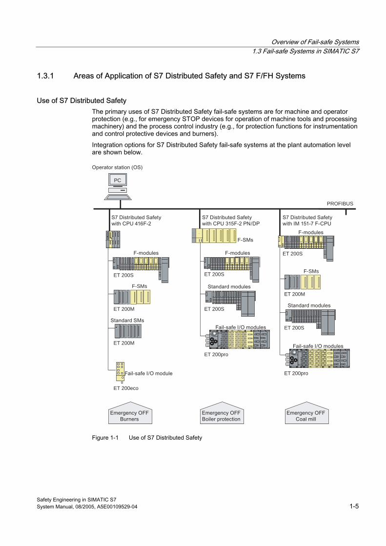
Use of S7 Distributed Safety The primary uses of S7 Distributed Safety fail-safe systems are for machine and operator protection (e.g., for emergency STOP devices for operation of machine tools and processing machinery) and the process control industry (e.g., for protection functions for instrumentation and control protective devices and burners).
Integration options for S7 Distributed Safety fail-safe systems at the plant automation level are shown below.
PROFIBUS
PC
ET 200SET 200M
ET 200M
ET 200S
F-SMs
ET 200S
ET 200S
ET 200pro
ET 200S
F-SMs
ET 200M
ET 200pro
ET 200eco
Figure 1-1 Use of S7 Distributed Safety
Overview of Fail-safe Systems 1.3 Fail-safe Systems in SIMATIC S7
Safety Engineering in SIMATIC S7 1-6 System Manual, 08/2005, A5E00109529-04
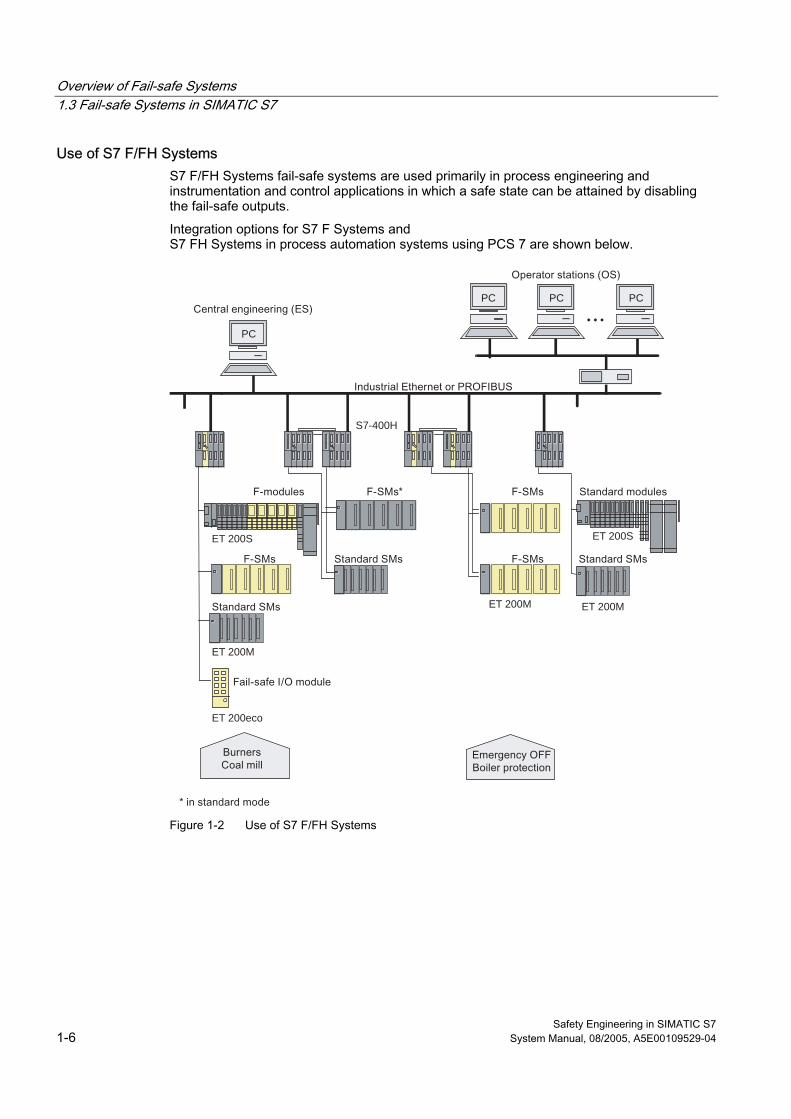
Use of S7 F/FH Systems S7 F/FH Systems fail-safe systems are used primarily in process engineering and instrumentation and control applications in which a safe state can be attained by disabling the fail-safe outputs.
Integration options for S7 F Systems and S7 FH Systems in process automation systems using PCS 7 are shown below.
PC
PC
• • •
PC PC
ET 200M
ET 200M ET 200M
ET 200S ET 200S
S7-400H
ET 200eco
Figure 1-2 Use of S7 F/FH Systems
Overview of Fail-safe Systems 1.3 Fail-safe Systems in SIMATIC S7
Safety Engineering in SIMATIC S7 System Manual, 08/2005, A5E00109529-04 1-7
1.3.2 Performance Characteristics of S7 Distributed Safety and S7 F/FH Systems
Common Characteristics of S7 Distributed Safety and S7 F/FH Systems S7 Distributed Safety and S7 F/FH Systems have the following important characteristics in common:
• Integration in S7-300 or S7-400 automation systems; the automation task determines the system design, and fail-safe engineering is integrated into the system
• Execution of standard control functions and protection functions on the same system (standard system with fail-safe capability, which eliminates the need for dedicated fail-safe solutions)
• Connection of distributed I/O via PROFIBUS DP with PROFIsafe
• Use of standard PROFIBUS components (copper and fiber-optic cable technology)
• Configuration integrated in STEP 7, same as for standard automation systems
• Creation of safety program using standard programming languages of STEP 7
• Flexible adaptation to the task requirements by providing a wide range of fail-safe I/O
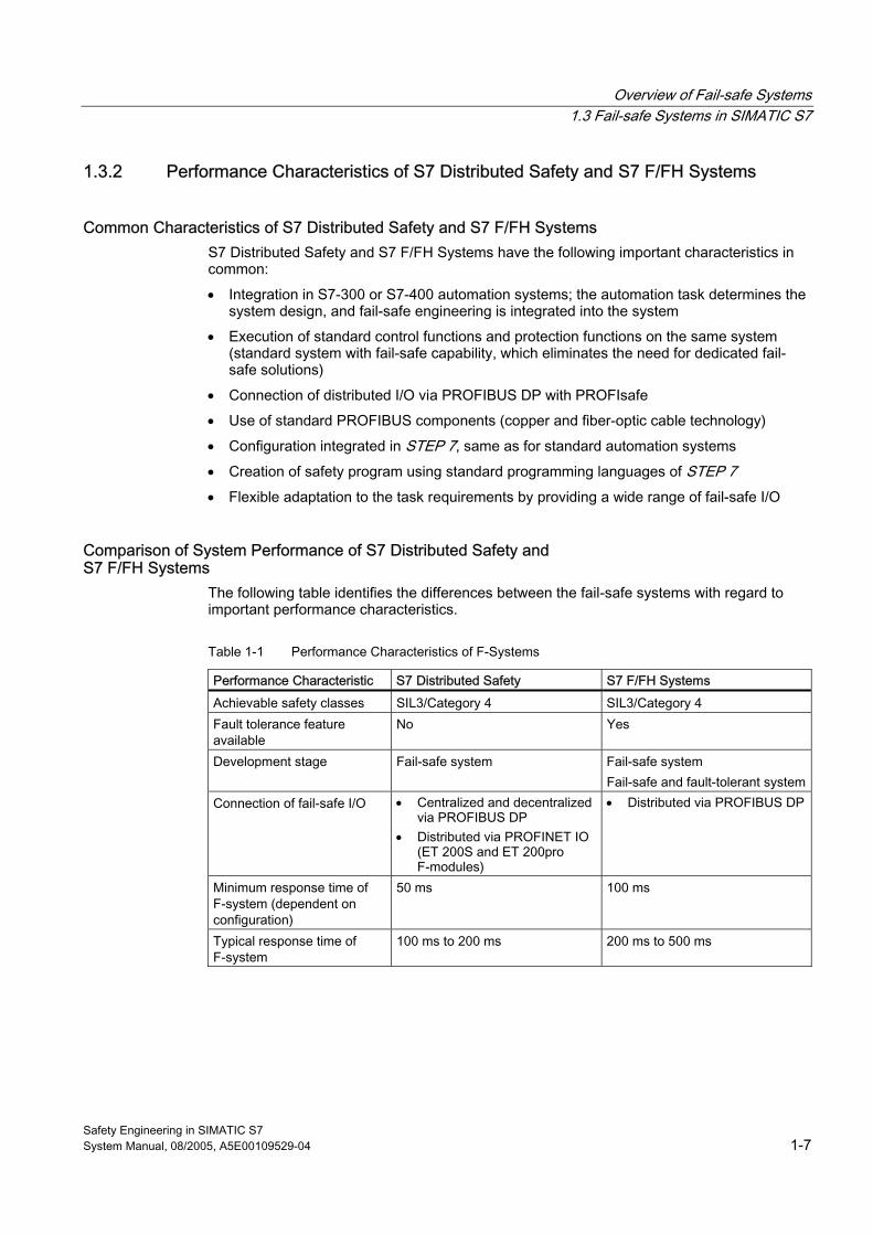
Comparison of System Performance of S7 Distributed Safety and S7 F/FH Systems
The following table identifies the differences between the fail-safe systems with regard to important performance characteristics.
Table 1-1 Performance Characteristics of F-Systems
Performance Characteristic S7 Distributed Safety S7 F/FH Systems Achievable safety classes SIL3/Category 4 SIL3/Category 4 Fault tolerance feature available
No Yes
Development stage Fail-safe system Fail-safe system Fail-safe and fault-tolerant system
Connection of fail-safe I/O • Centralized and decentralized via PROFIBUS DP
• Distributed via PROFINET IO (ET 200S and ET 200pro F-modules)
• Distributed via PROFIBUS DP
Minimum response time of F-system (dependent on configuration)
50 ms 100 ms
Typical response time of F-system
100 ms to 200 ms 200 ms to 500 ms
Overview of Fail-safe Systems 1.3 Fail-safe Systems in SIMATIC S7
Safety Engineering in SIMATIC S7 1-8 System Manual, 08/2005, A5E00109529-04
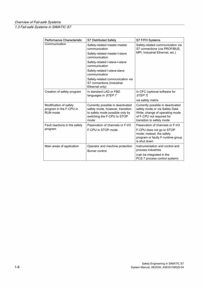
Performance Characteristic S7 Distributed Safety S7 F/FH Systems Communication Safety-related master-master
communication Safety-related master-I-slave communication Safety-related I-slave-I-slave communication Safety-related I-slave-slave communication Safety-related communication via S7 connections (Industrial Ethernet only)
Safety-related communication via S7 connections (via PROFIBUS, MPI, Industrial Ethernet, etc.)
Creation of safety program In standard LAD or FBD languages in STEP 7
In CFC (optional software for STEP 7) via safety matrix
Modification of safety program in the F-CPU in RUN mode
Currently possible in deactivated safety mode, however, transition to safety mode possible only by switching the F-CPU to STOP mode
Currently possible in deactivated safety mode or via Safety Data Write; change of operating mode of F-CPU not required for transition to safety mode
Fault reactions in the safety program
Passivation of channels or F-I/O F-CPU in STOP mode
Passivation of channels or F-I/O F-CPU does not go to STOP mode; instead, the safety program or faulty F-runtime group is shut down
Main areas of application Operator and machine protection Burner control
Instrumentation and control and process industries (can be integrated in the PCS 7 process control system)
Overview of Fail-safe Systems 1.3 Fail-safe Systems in SIMATIC S7
Safety Engineering in SIMATIC S7 System Manual, 08/2005, A5E00109529-04 1-9
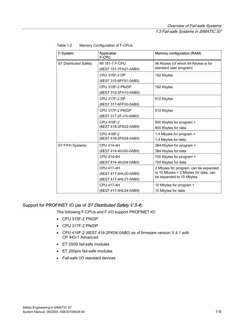
Table 1-2 Memory Configuration of F-CPUs
F-System Applicable F-CPU
Memory configuration (RAM)
IM 151-7 F-CPU (6ES7 151-7FA01-0AB0)
96 Kbytes (of which 64 Kbytes is for standard user program)
CPU 315F-2 DP (6ES7 315-6FF01-0AB0)
192 Kbytes
CPU 315F-2 PN/DP (6ES7 315-2FH10-0AB0)
192 Kbytes
CPU 317F-2 DP (6ES7 317-6FF00-0AB0)
512 Kbytes
CPU 317F-2 PN/DP (6ES7 317-2FJ10-0AB0)
512 Kbytes
CPU 416F-2 (6ES7 416-2FK02-0AB0)
800 Kbytes for program + 800 Kbytes for data
S7 Distributed Safety
CPU 416F-2 (6ES7 416-2FK04-0AB0)
1.4 Mbytes for program + 1.4 Mbytes for data
CPU 414-4H (6ES7 414-4HJ00-0AB0)
384 Kbytes for program + 384 Kbytes for data
CPU 414-4H (6ES7 414-4HJ04-0AB0)
700 Kbytes for program + 700 Kbytes for data
CPU 417-4H (6ES7 417-4HL00-0AB0) (6ES7 417-4HL01-0AB0)
2 Mbytes for program, can be expanded to 10 Mbytes + 2 Mbytes for data, can be expanded to 10 Mbytes
S7 F/FH Systems
CPU 417-4H (6ES7 417-4HL04-0AB0)
10 Mbytes for program + 10 Mbytes for data
Support for PROFINET IO (as of S7 Distributed Safety V 5.4): The following F-CPUs and F-I/O support PROFINET IO:
• CPU 315F-2 PN/DP
• CPU 317F-2 PN/DP
• CPU 416F-2 (6ES7 416-2FK04-0AB0) as of firmware version V 4.1 with CP 443-1 Advanced
• ET 200S fail-safe modules
• ET 200pro fail-safe modules
• Fail-safe I/O standard devices
Overview of Fail-safe Systems 1.4 Components of S7 Distributed Safety and S7 F/FH Systems
Safety Engineering in SIMATIC S7 1-10 System Manual, 08/2005, A5E00109529-04
1.4 1.4 Components of S7 Distributed Safety and S7 F/FH Systems
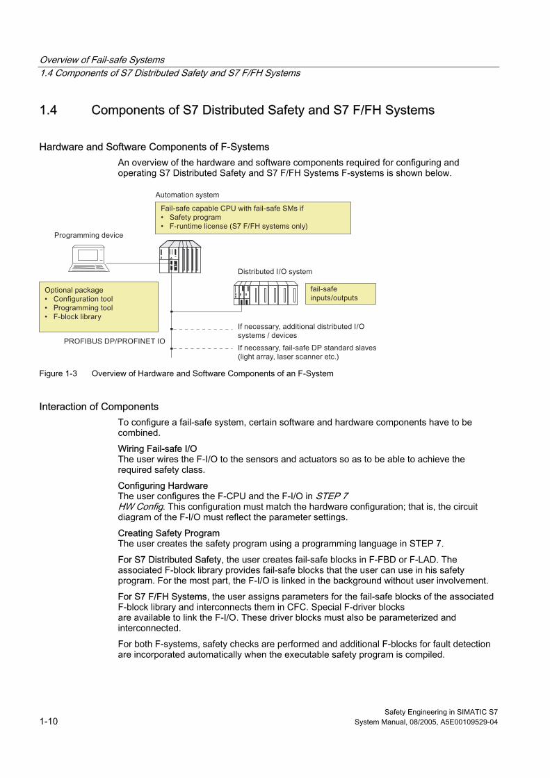
Hardware and Software Components of F-Systems An overview of the hardware and software components required for configuring and operating S7 Distributed Safety and S7 F/FH Systems F-systems is shown below.
Figure 1-3 Overview of Hardware and Software Components of an F-System
Interaction of Components To configure a fail-safe system, certain software and hardware components have to be combined.
Wiring Fail-safe I/O The user wires the F-I/O to the sensors and actuators so as to be able to achieve the required safety class.
Configuring Hardware The user configures the F-CPU and the F-I/O in STEP 7 HW Config. This configuration must match the hardware configuration; that is, the circuit diagram of the F-I/O must reflect the parameter settings.
Creating Safety Program The user creates the safety program using a programming language in STEP 7.
For S7 Distributed Safety, the user creates fail-safe blocks in F-FBD or F-LAD. The associated F-block library provides fail-safe blocks that the user can use in his safety program. For the most part, the F-I/O is linked in the background without user involvement.
For S7 F/FH Systems, the user assigns parameters for the fail-safe blocks of the associated F-block library and interconnects them in CFC. Special F-driver blocks are available to link the F-I/O. These driver blocks must also be parameterized and interconnected.
For both F-systems, safety checks are performed and additional F-blocks for fault detection are incorporated automatically when the executable safety program is compiled.
Overview of Fail-safe Systems 1.4 Components of S7 Distributed Safety and S7 F/FH Systems
Safety Engineering in SIMATIC S7 System Manual, 08/2005, A5E00109529-04 1-11
1.4.1 Hardware Components
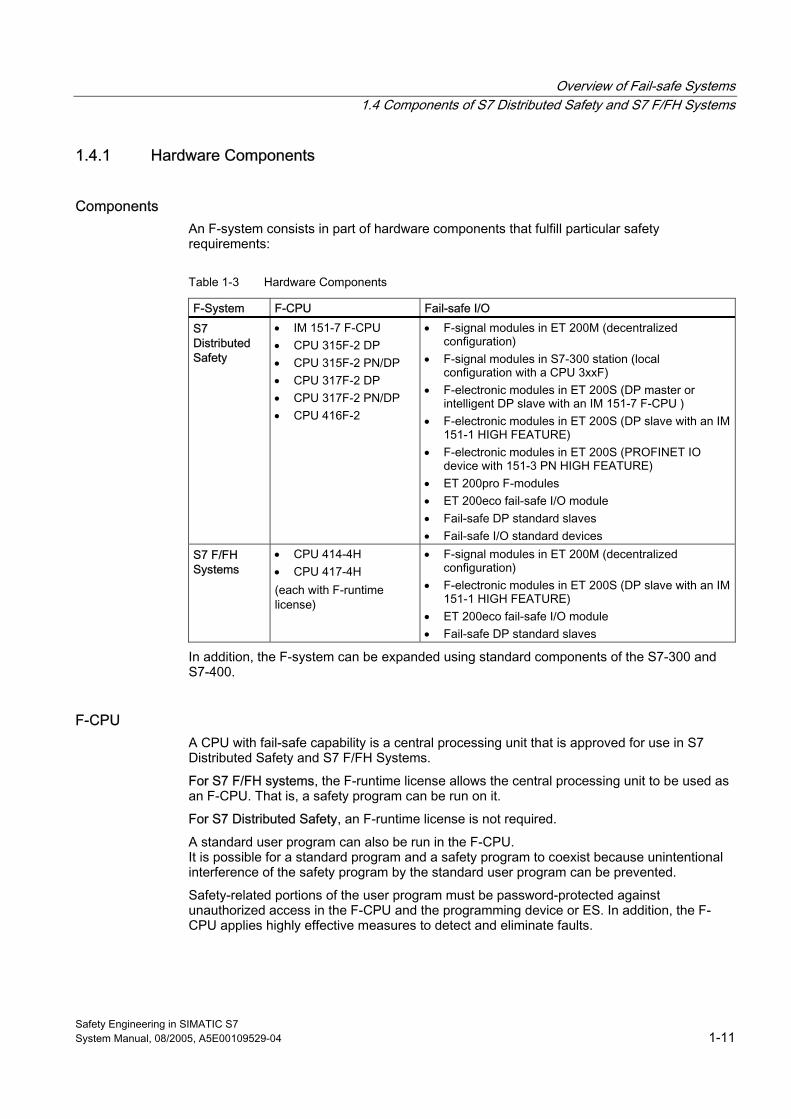
Components An F-system consists in part of hardware components that fulfill particular safety requirements:
Table 1-3 Hardware Components
F-System F-CPU Fail-safe I/O S7 Distributed Safety
• IM 151-7 F-CPU • CPU 315F-2 DP • CPU 315F-2 PN/DP • CPU 317F-2 DP • CPU 317F-2 PN/DP • CPU 416F-2
• F-signal modules in ET 200M (decentralized configuration)
• F-signal modules in S7-300 station (local configuration with a CPU 3xxF)
• F-electronic modules in ET 200S (DP master or intelligent DP slave with an IM 151-7 F-CPU )
• F-electronic modules in ET 200S (DP slave with an IM 151-1 HIGH FEATURE)
• F-electronic modules in ET 200S (PROFINET IO device with 151-3 PN HIGH FEATURE)
• ET 200pro F-modules • ET 200eco fail-safe I/O module • Fail-safe DP standard slaves • Fail-safe I/O standard devices
S7 F/FH Systems
• CPU 414-4H • CPU 417-4H (each with F-runtime license)
• F-signal modules in ET 200M (decentralized configuration)
• F-electronic modules in ET 200S (DP slave with an IM 151-1 HIGH FEATURE)
• ET 200eco fail-safe I/O module • Fail-safe DP standard slaves
In addition, the F-system can be expanded using standard components of the S7-300 and S7-400.
F-CPU A CPU with fail-safe capability is a central processing unit that is approved for use in S7 Distributed Safety and S7 F/FH Systems.
For S7 F/FH systems, the F-runtime license allows the central processing unit to be used as an F-CPU. That is, a safety program can be run on it.
For S7 Distributed Safety, an F-runtime license is not required.
A standard user program can also be run in the F-CPU. It is possible for a standard program and a safety program to coexist because unintentional interference of the safety program by the standard user program can be prevented.
Safety-related portions of the user program must be password-protected against unauthorized access in the F-CPU and the programming device or ES. In addition, the F-CPU applies highly effective measures to detect and eliminate faults.
Overview of Fail-safe Systems 1.4 Components of S7 Distributed Safety and S7 F/FH Systems
Safety Engineering in SIMATIC S7 1-12 System Manual, 08/2005, A5E00109529-04
Warning You can use the following F-CPUs in S7 Distributed Safety: IM 151-7 F-CPU, CPU 315F-2 DP, CPU 315F-2 PN/DP, CPU 317F-2 DP, CPU 317F-2 PN/DP and CPU 416F-2. Note that these F-CPUs cannot be used in S7 F/FH Systems.
You can use the following F-CPUs in S7 F/FH Systems: CPU 414-4H and CPU 417-4H. Note that these F-CPUs can not be used in S7 Distributed Safety.
Fail-safe I/O The following fail-safe I/O are available:
For S7 Distributed Safety and S7 F/FH Systems:
• S7-300 fail-safe signal modules (F-SMs)
• ET 200S fail-safe power and electronic modules (ET 200S F-modules)
• ET 200eco fail-safe I/O module (ET 200eco F-module)
• Fail-safe DP standard slaves
For S7 Distributed Safety:
• ET 200pro fail-safe electronic modules
• Fail-safe I/O standard device
S7-300 Fail-safe Signal Modules The following fail-safe signal modules (F-SMs) are available: • Fail-safe digital input modules:
– SM 326; DI 8 ☓ NAMUR, with diagnostic interrupt
– SM 326; DI 24 ☓ 24 VDC, with diagnostic interrupt • Fail-safe digital output modules:
– SM 326; DO 10 ☓ 24 VDC/2 A, with diagnostic interrupt
– SM 326; DO 8 ☓ 24 VDC/2 A, with diagnostic interrupt • Fail-safe analog input module: SM 336; AI 6 ☓ 13 bits, with diagnostic interrupt F-SMs can also be used as standard SMs with standard CPUs in standard applications. From a user standpoint, the F-SMs can be distinguished from most standard SMs in that they have diagnostic interrupt capability. In S7 Distributed Safety, the F-SMs can be operated as decentralized modules in ET 200M and as centralized modules in an S7-300 station. In S7 F/FH Systems, the F-SMs can generally be operated only in the ET 200M distributed I/O system. Exception: The SM 326; DO 8 ☓ DC 24V/2A can only be operated as a fail-safe signal module. You can, however, installed it centrally with all F-CPUs of the S7-300 spectrum with: • CPU 315F-2 DP (6ES7 315-6FF01-0AB0) beginning with firmware version V 2.0.9 and • CPU 315F-2 DP (6ES7 317-6FF00-0AB0) beginning with firmware version V 2.1.4. The module can be operated in a distributed configuration in in S7 Distributed Safety.
Overview of Fail-safe Systems 1.4 Components of S7 Distributed Safety and S7 F/FH Systems
Safety Engineering in SIMATIC S7 System Manual, 08/2005, A5E00109529-04 1-13
Restrictions on the Use of S7-300 Standard SMs The restrictions for fault-tolerant systems are applicable to the use of S7-300 standard SMs in S7 F/FH Systems (see Automation System S7-400H Fault-Tolerant Systems manual).
For the restrictions for S7-300 standard SMs in safety mode of F-SMs, refer to the Automation System S7-300 Fail-safe Signal Modules manual.
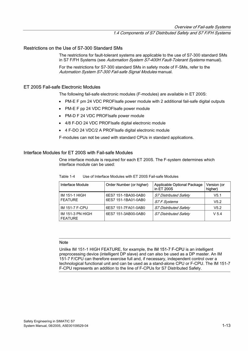
ET 200S Fail-safe Electronic Modules The following fail-safe electronic modules (F-modules) are available in ET 200S:
• PM-E F pm 24 VDC PROFIsafe power module with 2 additional fail-safe digital outputs
• PM-E F pp 24 VDC PROFIsafe power module
• PM-D F 24 VDC PROFIsafe power module
• 4/8 F-DO 24 VDC PROFIsafe digital electronic module
• 4 F-DO 24 VDC/2 A PROFIsafe digital electronic module
F-modules can not be used with standard CPUs in standard applications.
Interface Modules for ET 200S with Fail-safe Modules One interface module is required for each ET 200S. The F-system determines which interface module can be used:
Table 1-4 Use of Interface Modules with ET 200S Fail-safe Modules
Interface Module Order Number (or higher) Applicable Optional Package in ET 200S
Version (or higher)
S7 Distributed Safety V5.1 IM 151-1 HIGH FEATURE
6ES7 151-1BA00-0AB0 6ES7 151-1BA01-0AB0 S7 F Systems V5.2
IM 151-7 F-CPU 6ES7 151-7FA01-0AB0 S7 Distributed Safety V5.2 IM 151-3 PN HIGH FEATURE
6ES7 151-3AB00-0AB0 S7 Distributed Safety V 5.4
Note Unlike IM 151-1 HIGH FEATURE, for example, the IM 151-7 F-CPU is an intelligent preprocessing device (intelligent DP slave) and can also be used as a DP master. An IM 151-7 F/CPU can therefore exercise full and, if necessary, independent control over a technological functional unit and can be used as a stand-alone CPU or F-CPU. The IM 151-7 F-CPU represents an addition to the line of F-CPUs for S7 Distributed Safety.
Overview of Fail-safe Systems 1.4 Components of S7 Distributed Safety and S7 F/FH Systems
Safety Engineering in SIMATIC S7 1-14 System Manual, 08/2005, A5E00109529-04
ET 200pro Fail-safe Modules The following fail-safe electronic modules (F-modules for short) are available for an ET 200pro:
• 8/16 F-DI DC24V PROFIsafe Digital Electronic Module
• 4/8 F-DI/4 F-DO DC24V/2A PROFIsafe Digital Electronic Module
ET 200eco Fail-safe I/O Module The following fail-safe I/O modules (F-modules) are available in ET 200eco:
• 4/8 F-DI 24 VDC PROFIsafe
Fail-safe DP Standard Slaves Fail-safe DP standard slaves are standard slaves that are operated on PROFIBUS with the DP protocol and the PROFIsafe bus profile. Their behavior must comply with IEC 61784-1:2002 Ed1 CP 3/1 and the PROFIsafe bus profile.
Fail-safe DP standard slaves that are used in a mixed configurations on PROFIBUS DP and PROFINET IO after IE/PB links, must support the PROFIsafe bus profile in the V2 mode.
A GSD file is used to configure fail-safe DP standard slaves.
Fail-safe IO Standard Devices Fail-safe I/O standard slaves are standard devices that are operated on PROFINET with the I/O protocol and the PROFIsafe (V2 mode) bus profile. They must behave in accordance with IEC 61784-1:2002 Ed1 CP 3/3 and the PROFIsafe bus profile (V2 MODE). A GSDML file is used to configure them.
Overview of Fail-safe Systems 1.4 Components of S7 Distributed Safety and S7 F/FH Systems
Safety Engineering in SIMATIC S7 System Manual, 08/2005, A5E00109529-04 1-15
1.4.2 Software Components
Introduction The software components of an F-system include the following:
• Optional package on the programming device or ES for configuring and programming the F-system
• Safety program in the F-CPU
You also need the STEP 7 basic software on the programming device or ES for configuring and programming the standard automation system.
Für For S7 F/FH systems, you also need the CFC and S7-SCL add-on software for STEP 7 and, when applicable, PCS 7.
Optional Packages for Configuring and Programming F-Systems The two optional packages are available for configuring and programming F-systems as shown in the following table.
Table 1-5 Optional Packages for Configuration and Programming
Optional Package Order Number For F-System Scope S7 Distributed Safety
6ES7 833-1FC02-0YX0
S7 Distributed Safety
Configuration and programming software with F-block library for: • IM 151-7 F-CPU, CPU 315F-2 DP,
CPU 315F-2 PN/DP, CPU 317F-2 DP, CPU 317F-2 PN/DP, CPU 416F-2
• ET 200S F-modules • ET 200pro F-modules • ET 200eco F-module • S7-300 F-SMs • Fail-safe DP standard slaves • Fail-safe I/O standard devices
S7 F Systems 6ES7 833-1CC00-0YX0
S7 F/FH Systems
Configuration and programming software with F-block library for: • CPU 414-4H, CPU 417-4H • ET 200S F-modules • ET 200eco F-module • S7-300 F-SMs • Fail-safe DP standard slaves
The user receives the following with these optional packages:
• Support for configuring the F-I/O in STEP 7 with HW Config.
• F-library with fail-safe blocks for creating safety programs
• Support for creating the safety program and integrating fault detection functions in the safety program

Overview of Fail-safe Systems 1.4 Components of S7 Distributed Safety and S7 F/FH Systems
Safety Engineering in SIMATIC S7 1-16 System Manual, 08/2005, A5E00109529-04
Programming Language Different programming languages are used to create safety programs:
Table 1-6 Programming Languages
F-System Programming Language
Description
S7 Distributed Safety
F-LAD, F-FBD • The primary difference between the F-LAD and F-FBD programming languages and the standard LAD and FBD languages in STEP 7 lies in the limitations in the instruction set and data types.
• F-application blocks from the Distributed Safety F-library or custom F-libraries can be used.
S7 F/FH Systems
CFC • Use of optional CFC software in STEP 7 • Special F-blocks in the Failsafe Blocks F-library must be used.
Creating a Safety Program for S7 Distributed Safety The user creates safety programs with F-FBD or F-LAD in fail-safe FBs and FCs. The F-library provided contains F-application blocks that the user can incorporate into his safety program.
The user also has the option of creating his own F-libraries for S7 Distributed Safety (custom F-libraries).
Creating a Safety Program for S7 F/FH Systems The user creates safety programs with CFC by interconnecting fail-safe blocks in the F-library provided with the S7 F Systems optional package.
Additional Information For detailed information on configuring S7 Distributed Safety and S7 F/FH Systems, refer to "Configuring F-Systems". Programming of F-systems is described in "Programming F-Systems".
Overview of Fail-safe Systems 1.5 Guide to Working with F-Systems
Safety Engineering in SIMATIC S7 System Manual, 08/2005, A5E00109529-04 1-17
1.5 1.5 Guide to Working with F-Systems
Introduction This section describes the basic procedure for working with fail-safe systems. Only the relevant steps for F-systems that differ from the standard procedure are presented.
Planning tasks that depend on the process, such as creating a flowchart or process tag list, defining a structure, etc., are not described here.
Example Projects You will find introductory example projects for configuration and programming of:
• S7 Distributed Safety in S7 Distributed Safety Getting Started
• S7 Distributed Safety in S7 Distributed Safety Configuring and Programming manual
• S7 F/FH Systems in Programmable Controllers S7 F/FH manual
• S7 F/FH Systems in step7\Examples directory
Planning a System When planning a system, the planner specifies the applicable safety class (SIL/Category) for each required safety function based on a risk assessment. This is then used to determine the component requirements for implementing the safety functions (programmable logic controllers, sensors, actuators). These decisions influence additional activities such as hardware design, configuration, and programming.
Note A functional division of standard and safety functions is important for planning.
Overview of Fail-safe Systems 1.5 Guide to Working with F-Systems
Safety Engineering in SIMATIC S7 1-18 System Manual, 08/2005, A5E00109529-04
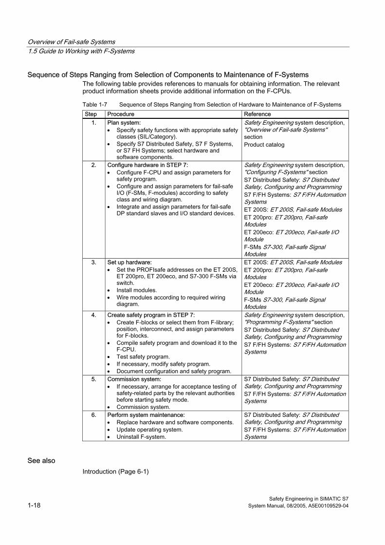
Sequence of Steps Ranging from Selection of Components to Maintenance of F-Systems The following table provides references to manuals for obtaining information. The relevant product information sheets provide additional information on the F-CPUs.
Table 1-7 Sequence of Steps Ranging from Selection of Hardware to Maintenance of F-Systems Step Procedure Reference
1.
Plan system: • Specify safety functions with appropriate safety
classes (SIL/Category). • Specify S7 Distributed Safety, S7 F Systems,
or S7 FH Systems; select hardware and software components.
Safety Engineering system description, "Overview of Fail-safe Systems" section Product catalog
2. Configure hardware in STEP 7: • Configure F-CPU and assign parameters for
safety program. • Configure and assign parameters for fail-safe
I/O (F-SMs, F-modules) according to safety class and wiring diagram.
• Integrate and assign parameters for fail-safe DP standard slaves and I/O standard devices.
Safety Engineering system description, "Configuring F-Systems" section S7 Distributed Safety: S7 Distributed Safety, Configuring and Programming S7 F/FH Systems: S7 F/FH Automation Systems ET 200S: ET 200S, Fail-safe Modules ET 200pro: ET 200pro, Fail-safe Modules ET 200eco: ET 200eco, Fail-safe I/O Module F-SMs S7-300, Fail-safe Signal Modules
3. Set up hardware: • Set the PROFIsafe addresses on the ET 200S,
ET 200pro, ET 200eco, and S7-300 F-SMs via switch.
• Install modules. • Wire modules according to required wiring
diagram.
ET 200S: ET 200S, Fail-safe Modules ET 200pro: ET 200pro, Fail-safe Modules ET 200eco: ET 200eco, Fail-safe I/O Module F-SMs S7-300, Fail-safe Signal Modules
4. Create safety program in STEP 7: • Create F-blocks or select them from F-library;
position, interconnect, and assign parameters for F-blocks.
• Compile safety program and download it to the F-CPU.
• Test safety program. • If necessary, modify safety program. • Document configuration and safety program.
Safety Engineering system description, "Programming F-Systems" section S7 Distributed Safety: S7 Distributed Safety, Configuring and Programming S7 F/FH Systems: S7 F/FH Automation Systems
5. Commission system: • If necessary, arrange for acceptance testing of
safety-related parts by the relevant authorities before starting safety mode.
• Commission system.
S7 Distributed Safety: S7 Distributed Safety, Configuring and Programming S7 F/FH Systems: S7 F/FH Automation Systems
6. Perform system maintenance: • Replace hardware and software components. • Update operating system. • Uninstall F-system.
S7 Distributed Safety: S7 Distributed Safety, Configuring and Programming S7 F/FH Systems: S7 F/FH Automation Systems
See also Introduction (Page 6-1)
Safety Engineering in SIMATIC S7 System Manual, 08/2005, A5E00109529-04 2-1
Configurations and Help with Selection 22.1 2.1 Introduction
Overview This chapter includes a description of the basic configuration of S7 Distributed Safety and S7 F/FH Systems fail-safe systems.
It also provides information about the configuration variants depending on the availability requirements of the F-system.
In the last part of the chapter, we present the main criteria used by customers to determine which fail-safe system - S7 Distributed Safety, S7 F Systems, or S7 FH Systems - is right for their automation task.
Additional Information For detailed information on the F-I/O, refer to:
• Automation System S7-300 Fail-safe Signal Modules manual
• ET 200S Distributed I/O System Fail-safe Modules manual
• ET 200pro Distributed I/O Device, Fail-safe Modules manual
• ET 200eco Distributed I/O Station Fail-safe I/O Module manual
Configurations and Help with Selection 2.2 Configuration of F-Systems
Safety Engineering in SIMATIC S7 2-2 System Manual, 08/2005, A5E00109529-04
2.2 2.2 Configuration of F-Systems
Basic Configurations This chapter describes the three basic configurations for F-systems:
• S7 Distributed Safety fail-safe system
• S7 F Systems fail-safe system
• S7 FH Systems fail-safe and fault-tolerant system
2.2.1 S7 Distributed Safety Fail-safe System
Components of S7 Distributed Safety System S7 Distributed Safety refers to a fail-safe automation system consisting of at least the following components:
• A central processing unit with fail-safe capability, such as CPU 315F-2 DP, on which a safety program is executed
• Fail-safe I/O, for example:
– Fail-safe signal modules (F-SMs) in a centralized configuration with CPU 315F-2 DP
– Fail-safe signal modules (F-SMs) in an ET 200M distributed I/O system
– Fail-safe modules in an ET 200S distributed I/O system
– Fail-safe modules in an ET 200pro distributed I/O device
– ET 200eco fail-safe I/O module
– Fail-safe DP standard slaves/standard I/O devices
Warning
You can use the following F-CPUs in S7 Distributed Safety: IM 151-7 F-CPU, CPU 315F-2 DP, CPU 315F-2 PN/DP, CPU 317F-2 DP, CPU 317F-2 PN/DP and CPU 416F-2. Note that these F-CPUs cannot be used in S7 F/FH Systems.
You can use the following F-CPUs in S7 F/FH Systems: CPU 414-4H and CPU 417-4H. Note that these F-CPUs can not be used in S7 Distributed Safety.
Configurations and Help with Selection 2.2 Configuration of F-Systems
Safety Engineering in SIMATIC S7 System Manual, 08/2005, A5E00109529-04 2-3
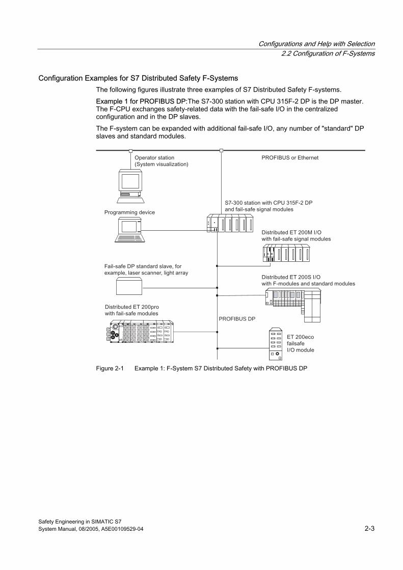
Configuration Examples for S7 Distributed Safety F-Systems The following figures illustrate three examples of S7 Distributed Safety F-systems.
Example 1 for PROFIBUS DP:The S7-300 station with CPU 315F-2 DP is the DP master. The F-CPU exchanges safety-related data with the fail-safe I/O in the centralized configuration and in the DP slaves.
The F-system can be expanded with additional fail-safe I/O, any number of "standard" DP slaves and standard modules.
PROFIBUS DP
Figure 2-1 Example 1: F-System S7 Distributed Safety with PROFIBUS DP
Configurations and Help with Selection 2.2 Configuration of F-Systems
Safety Engineering in SIMATIC S7 2-4 System Manual, 08/2005, A5E00109529-04
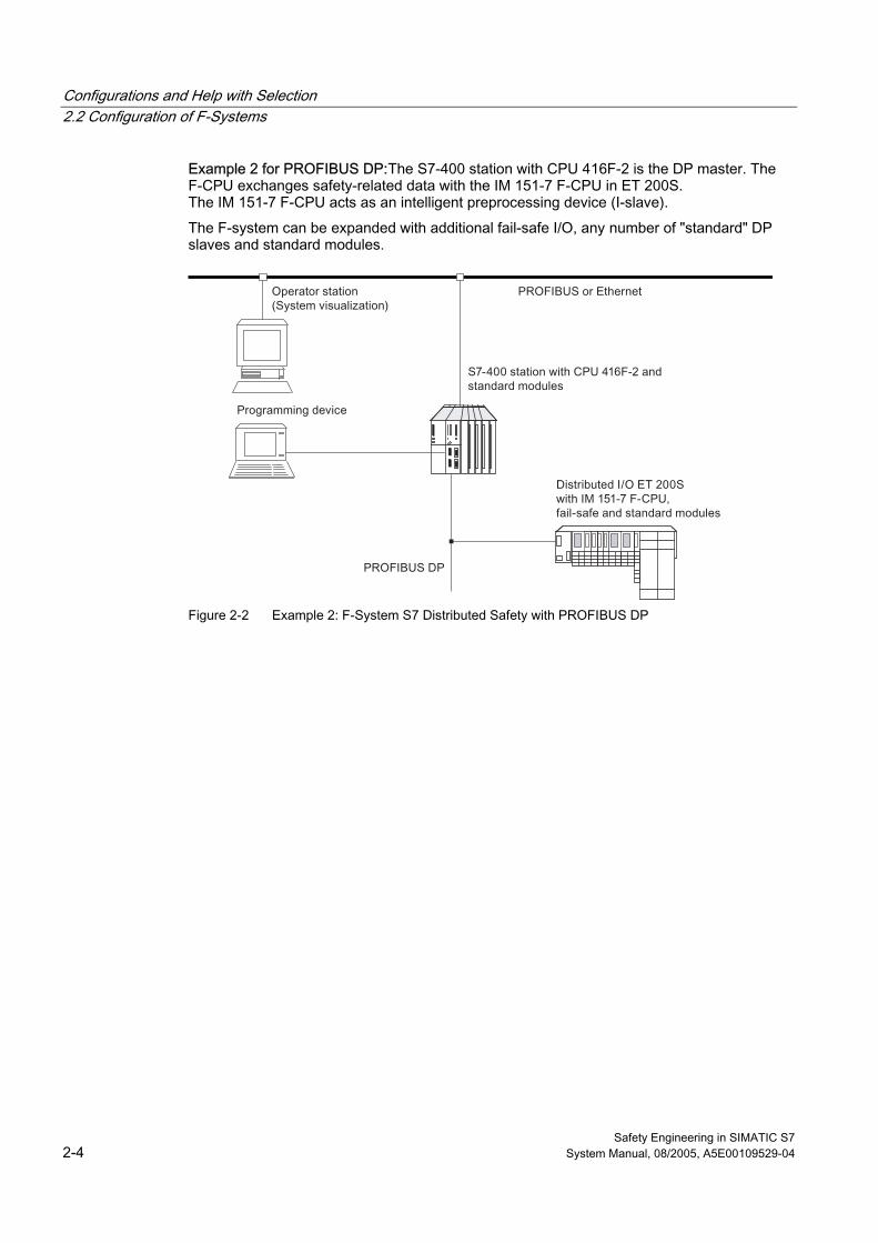
Example 2 for PROFIBUS DP:The S7-400 station with CPU 416F-2 is the DP master. The F-CPU exchanges safety-related data with the IM 151-7 F-CPU in ET 200S. The IM 151-7 F-CPU acts as an intelligent preprocessing device (I-slave).
The F-system can be expanded with additional fail-safe I/O, any number of "standard" DP slaves and standard modules.
Figure 2-2 Example 2: F-System S7 Distributed Safety with PROFIBUS DP
Configurations and Help with Selection 2.2 Configuration of F-Systems
Safety Engineering in SIMATIC S7 System Manual, 08/2005, A5E00109529-04 2-5
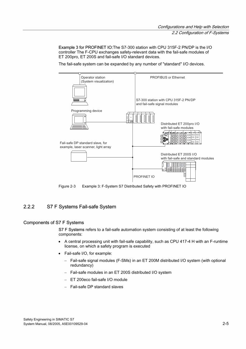
Example 3 for PROFINET IO:The S7-300 station with CPU 315F-2 PN/DP is the I/O controller The F-CPU exchanges safety-relevant data with the fail-safe modules of ET 200pro, ET 200S and fail-safe I/O standard devices.
The fail-safe system can be expanded by any number of "standard" I/O devices.
PROFINET IO
Figure 2-3 Example 3: F-System S7 Distributed Safety with PROFINET IO
2.2.2 S7 F Systems Fail-safe System
Components of S7 F Systems S7 F Systems refers to a fail-safe automation system consisting of at least the following components:
• A central processing unit with fail-safe capability, such as CPU 417-4 H with an F-runtime license, on which a safety program is executed
• Fail-safe I/O, for example:
– Fail-safe signal modules (F-SMs) in an ET 200M distributed I/O system (with optional redundancy)
– Fail-safe modules in an ET 200S distributed I/O system
– ET 200eco fail-safe I/O module
– Fail-safe DP standard slaves
Configurations and Help with Selection 2.2 Configuration of F-Systems
Safety Engineering in SIMATIC S7 2-6 System Manual, 08/2005, A5E00109529-04
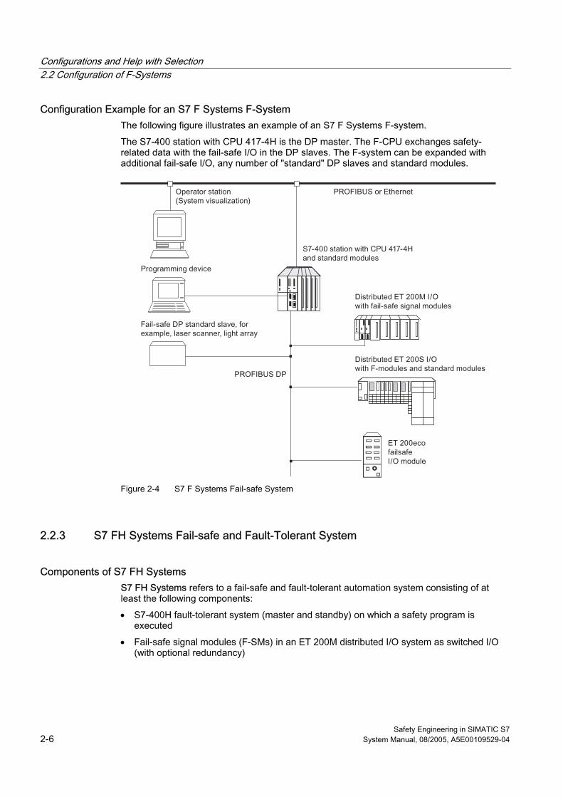
Configuration Example for an S7 F Systems F-System The following figure illustrates an example of an S7 F Systems F-system.
The S7-400 station with CPU 417-4H is the DP master. The F-CPU exchanges safety-related data with the fail-safe I/O in the DP slaves. The F-system can be expanded with additional fail-safe I/O, any number of "standard" DP slaves and standard modules.
Figure 2-4 S7 F Systems Fail-safe System
2.2.3 S7 FH Systems Fail-safe and Fault-Tolerant System
Components of S7 FH Systems S7 FH Systems refers to a fail-safe and fault-tolerant automation system consisting of at least the following components:
• S7-400H fault-tolerant system (master and standby) on which a safety program is executed
• Fail-safe signal modules (F-SMs) in an ET 200M distributed I/O system as switched I/O (with optional redundancy)
Configurations and Help with Selection 2.2 Configuration of F-Systems
Safety Engineering in SIMATIC S7 System Manual, 08/2005, A5E00109529-04 2-7
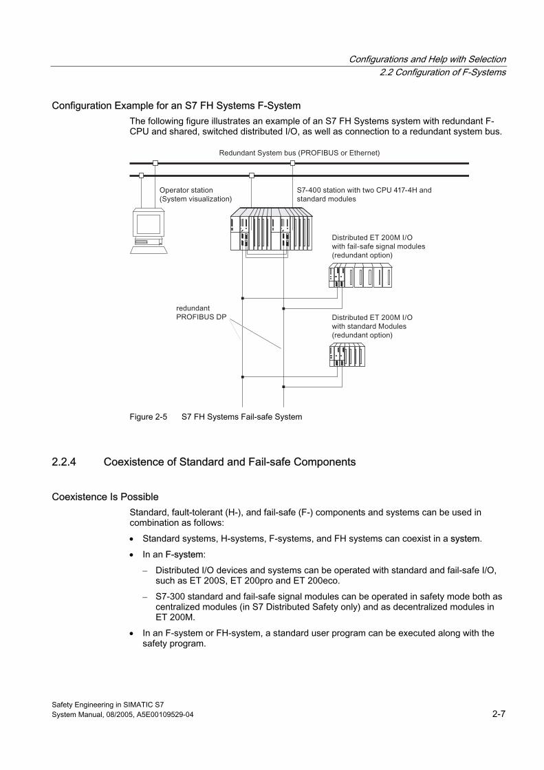
Configuration Example for an S7 FH Systems F-System The following figure illustrates an example of an S7 FH Systems system with redundant F-CPU and shared, switched distributed I/O, as well as connection to a redundant system bus.
Figure 2-5 S7 FH Systems Fail-safe System
2.2.4 Coexistence of Standard and Fail-safe Components
Coexistence Is Possible Standard, fault-tolerant (H-), and fail-safe (F-) components and systems can be used in combination as follows:
• Standard systems, H-systems, F-systems, and FH systems can coexist in a system.
• In an F-system:
– Distributed I/O devices and systems can be operated with standard and fail-safe I/O, such as ET 200S, ET 200pro and ET 200eco.
– S7-300 standard and fail-safe signal modules can be operated in safety mode both as centralized modules (in S7 Distributed Safety only) and as decentralized modules in ET 200M.
• In an F-system or FH-system, a standard user program can be executed along with the safety program.
Configurations and Help with Selection 2.2 Configuration of F-Systems
Safety Engineering in SIMATIC S7 2-8 System Manual, 08/2005, A5E00109529-04
Advantages Coexistence of F-components, H-components, and standard components has the following advantages: • It is possible to configure a totally integrated automation system that takes advantage of
standard CPU innovation. At the same time, fail-safe components are implemented independently of standard components such as FMs or CPs. The entire system is configured and programmed with standard tools such as HW Config, FBD, LAD, or CFC.
• The coexistence of standard and fail-safe program parts in one F-CPU reduces the cost of acceptance tests because program parts not required to be fail-safe can be swapped out to the standard user program. This reduces the size of the safety program, that is, the part of the program that must pass an acceptance test. Maintenance costs can also be reduced if as many functions as possible are moved to the standard user program, since the standard user program can be modified during operation.
Boundary Conditions for Coexistence
Warning For applications with safety class SIL2/Category 3 and lower, physical contact protection measures for standard components are sufficient (see the manuals for the F-CPU and F-I/O you are using). Applications with safety class SIL3/Category 4 require certain measures beyond physical contact protection to prevent hazardous overvoltages of F-circuits via the power supply and backplane bus, even in the event of a fault. Therefore, the following are provided for protection from backplane bus influence: • Safety protector for centralized and decentralized configuration of S7-300 F-SMs • For S7 F/FH Systems, PROFIBUS DP with fiber-optic cable design • ET 200S fail-safe modules and ET 200eco fail-safe I/O module exhibit a 250 VAC isolation
internally. To protect against influence by the power supply, configuration rules for power supplies, standard I/O, and fail-safe I/O are available (see Fail-safe I/O manuals).
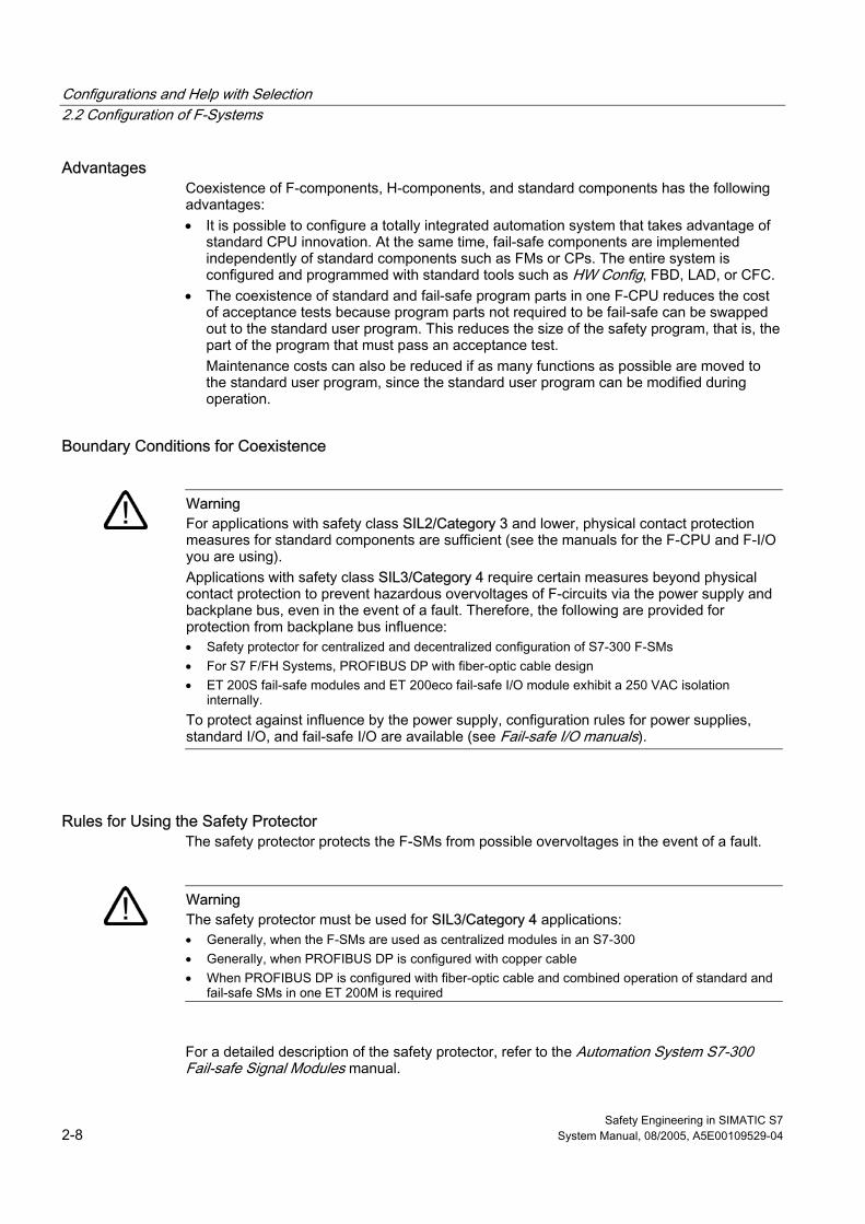
Rules for Using the Safety Protector The safety protector protects the F-SMs from possible overvoltages in the event of a fault.
Warning The safety protector must be used for SIL3/Category 4 applications: • Generally, when the F-SMs are used as centralized modules in an S7-300 • Generally, when PROFIBUS DP is configured with copper cable • When PROFIBUS DP is configured with fiber-optic cable and combined operation of standard and
fail-safe SMs in one ET 200M is required
For a detailed description of the safety protector, refer to the Automation System S7-300 Fail-safe Signal Modules manual.
Configurations and Help with Selection 2.3 Configuration Variants for Fail-safe Systems According to Availability Requirements
Safety Engineering in SIMATIC S7 System Manual, 08/2005, A5E00109529-04 2-9
2.3 2.3 Configuration Variants for Fail-safe Systems According to Availability Requirements
Options for Increasing Availability To increase availability of an automation system and, thus, to prevent process failures due to faults in the F-system, S7 F Systems fail-safe systems can be configured optionally as fault-tolerant systems (S7 FH Systems). This increased availability can be achieved by component redundancy (F-CPU, communication connections, and F-I/O).
For S7 F Systems, availability can be increased without fault-tolerant configuration. Fail-safe signal modules (F-SMs) can be used redundantly in one ET 200M or in several ET 200Ms.
The following section includes a description of how to achieve increased availability through redundancy of the F-CPU and F-I/O in S7 FH Systems.
Note Availability of the fail-safe CPUs in S7 Distributed Safety and S7 F Systems cannot be increased by using the "SW Redundancy" software package.
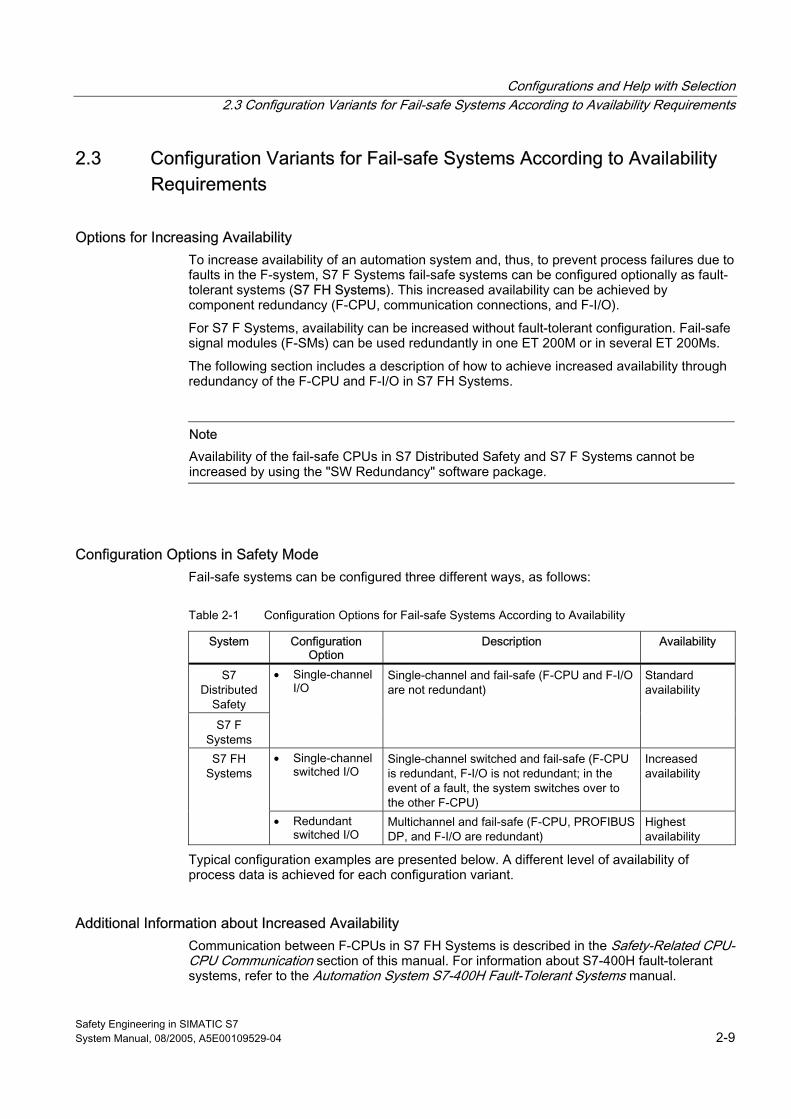
Configuration Options in Safety Mode Fail-safe systems can be configured three different ways, as follows:
Table 2-1 Configuration Options for Fail-safe Systems According to Availability
System Configuration Option
Description Availability
S7 Distributed
Safety
S7 F Systems
• Single-channel I/O
Single-channel and fail-safe (F-CPU and F-I/O are not redundant)
Standard availability
• Single-channel switched I/O
Single-channel switched and fail-safe (F-CPU is redundant, F-I/O is not redundant; in the event of a fault, the system switches over to the other F-CPU)
Increased availability
S7 FH Systems
• Redundant switched I/O
Multichannel and fail-safe (F-CPU, PROFIBUS DP, and F-I/O are redundant)
Highest availability
Typical configuration examples are presented below. A different level of availability of process data is achieved for each configuration variant.
Additional Information about Increased Availability Communication between F-CPUs in S7 FH Systems is described in the Safety-Related CPU-CPU Communication section of this manual. For information about S7-400H fault-tolerant systems, refer to the Automation System S7-400H Fault-Tolerant Systems manual.
Configurations and Help with Selection 2.3 Configuration Variants for Fail-safe Systems According to Availability Requirements
Safety Engineering in SIMATIC S7 2-10 System Manual, 08/2005, A5E00109529-04
Further information about PROFIBUS and Industrial Ethernet PROFIBUS or Industrial Ethernet is described in the SIMATIC NET hardware manuals PROFIBUS Networks and Industrial Twisted Pair and Fiber Optic Networks, respectively.
2.3.1 Single-channel I/O (S7 Distributed Safety)
Characteristics of Single-channel I/O In a single-channel configuration, fail-safe I/O are not redundant. The fail-safe I/O is addressed by one F-CPU.
Required Hardware Components for S7 Distributed Safety The hardware component requirements depend on whether the F-System is configured as a centralized system or as a decentralized system and whether the PROFIBUS DP is configured with a copper cable or a fiber-optic cable. The F-I/O is not redundant.
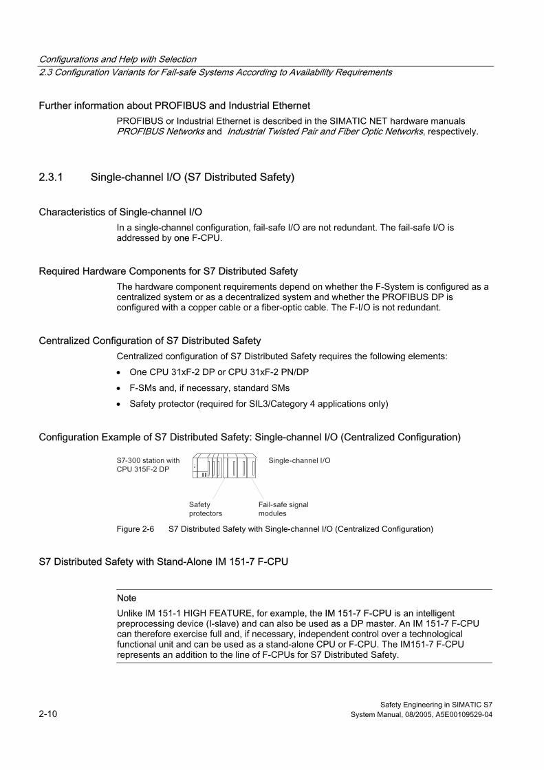
Centralized Configuration of S7 Distributed Safety Centralized configuration of S7 Distributed Safety requires the following elements:
• One CPU 31xF-2 DP or CPU 31xF-2 PN/DP
• F-SMs and, if necessary, standard SMs
• Safety protector (required for SIL3/Category 4 applications only)
Configuration Example of S7 Distributed Safety: Single-channel I/O (Centralized Configuration)
Figure 2-6 S7 Distributed Safety with Single-channel I/O (Centralized Configuration)
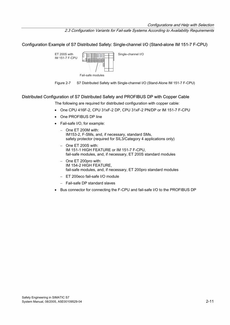
S7 Distributed Safety with Stand-Alone IM 151-7 F-CPU
Note Unlike IM 151-1 HIGH FEATURE, for example, the IM 151-7 F-CPU is an intelligent preprocessing device (I-slave) and can also be used as a DP master. An IM 151-7 F-CPU can therefore exercise full and, if necessary, independent control over a technological functional unit and can be used as a stand-alone CPU or F-CPU. The IM151-7 F-CPU represents an addition to the line of F-CPUs for S7 Distributed Safety.
Configurations and Help with Selection 2.3 Configuration Variants for Fail-safe Systems According to Availability Requirements
Safety Engineering in SIMATIC S7 System Manual, 08/2005, A5E00109529-04 2-11
Configuration Example of S7 Distributed Safety: Single-channel I/O (Stand-alone IM 151-7 F-CPU)
Figure 2-7 S7 Distributed Safety with Single-channel I/O (Stand-Alone IM 151-7 F-CPU)
Distributed Configuration of S7 Distributed Safety and PROFIBUS DP with Copper Cable The following are required for distributed configuration with copper cable:
• One CPU 416F-2, CPU 31xF-2 DP, CPU 31xF-2 PN/DP or IM 151-7 F-CPU
• One PROFIBUS DP line
• Fail-safe I/O, for example:
– One ET 200M with: IM153-2, F-SMs, and, if necessary, standard SMs, safety protector (required for SIL3/Category 4 applications only)
– One ET 200S with: IM 151-1 HIGH FEATURE or IM 151-7 F-CPU, fail-safe modules, and, if necessary, ET 200S standard modules
– One ET 200pro with: IM 154-2 HIGH FEATURE, fail-safe modules, and, if necessary, ET 200pro standard modules
– ET 200eco fail-safe I/O module
– Fail-safe DP standard slaves
• Bus connector for connecting the F-CPU and fail-safe I/O to the PROFIBUS DP
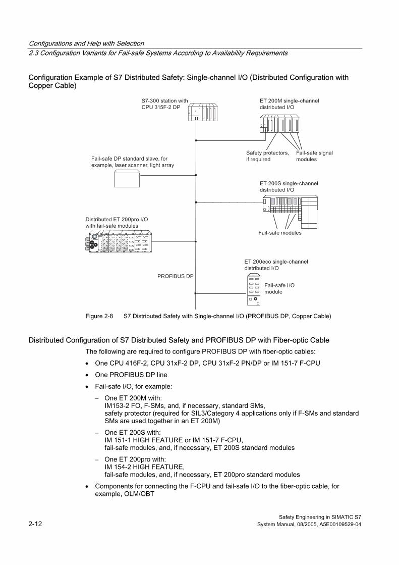
Configurations and Help with Selection 2.3 Configuration Variants for Fail-safe Systems According to Availability Requirements
Safety Engineering in SIMATIC S7 2-12 System Manual, 08/2005, A5E00109529-04
Configuration Example of S7 Distributed Safety: Single-channel I/O (Distributed Configuration with Copper Cable)
PROFIBUS DP
Figure 2-8 S7 Distributed Safety with Single-channel I/O (PROFIBUS DP, Copper Cable)
Distributed Configuration of S7 Distributed Safety and PROFIBUS DP with Fiber-optic Cable The following are required to configure PROFIBUS DP with fiber-optic cables:
• One CPU 416F-2, CPU 31xF-2 DP, CPU 31xF-2 PN/DP or IM 151-7 F-CPU
• One PROFIBUS DP line
• Fail-safe I/O, for example:
– One ET 200M with: IM153-2 FO, F-SMs, and, if necessary, standard SMs, safety protector (required for SIL3/Category 4 applications only if F-SMs and standard SMs are used together in an ET 200M)
– One ET 200S with: IM 151-1 HIGH FEATURE or IM 151-7 F-CPU, fail-safe modules, and, if necessary, ET 200S standard modules
– One ET 200pro with: IM 154-2 HIGH FEATURE, fail-safe modules, and, if necessary, ET 200pro standard modules
• Components for connecting the F-CPU and fail-safe I/O to the fiber-optic cable, for example, OLM/OBT
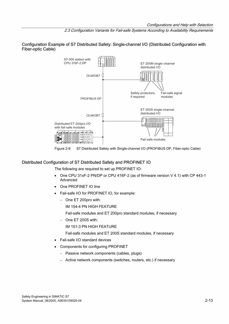
Configurations and Help with Selection 2.3 Configuration Variants for Fail-safe Systems According to Availability Requirements
Safety Engineering in SIMATIC S7 System Manual, 08/2005, A5E00109529-04 2-13
Configuration Example of S7 Distributed Safety: Single-channel I/O (Distributed Configuration with Fiber-optic Cable)
OLM/OBT
OLM/OBT
PROFIBUS DP
Figure 2-9 S7 Distributed Safety with Single-channel I/O (PROFIBUS DP, Fiber-optic Cable)
Distributed Configuration of S7 Distributed Safety and PROFINET IO The following are required to set up PROFINET IO:
• One CPU 31xF-2 PN/DP or CPU 416F-2 (as of firmware version V 4.1) with CP 443-1 Advanced
• One PROFINET IO line
• Fail-safe I/O for PROFINET IO, for example:
– One ET 200pro with:
IM 154-4 PN HIGH FEATURE
Fail-safe modules and ET 200pro standard modules, if necessary
– One ET 200S with:
IM 151-3 PN HIGH FEATURE
Fail-safe modules and ET 200S standard modules, if necessary
• Fail-safe I/O standard devices
• Components for configuring PROFINET
– Passive network components (cables, plugs)
– Active network components (switches, routers, etc.) if necessary
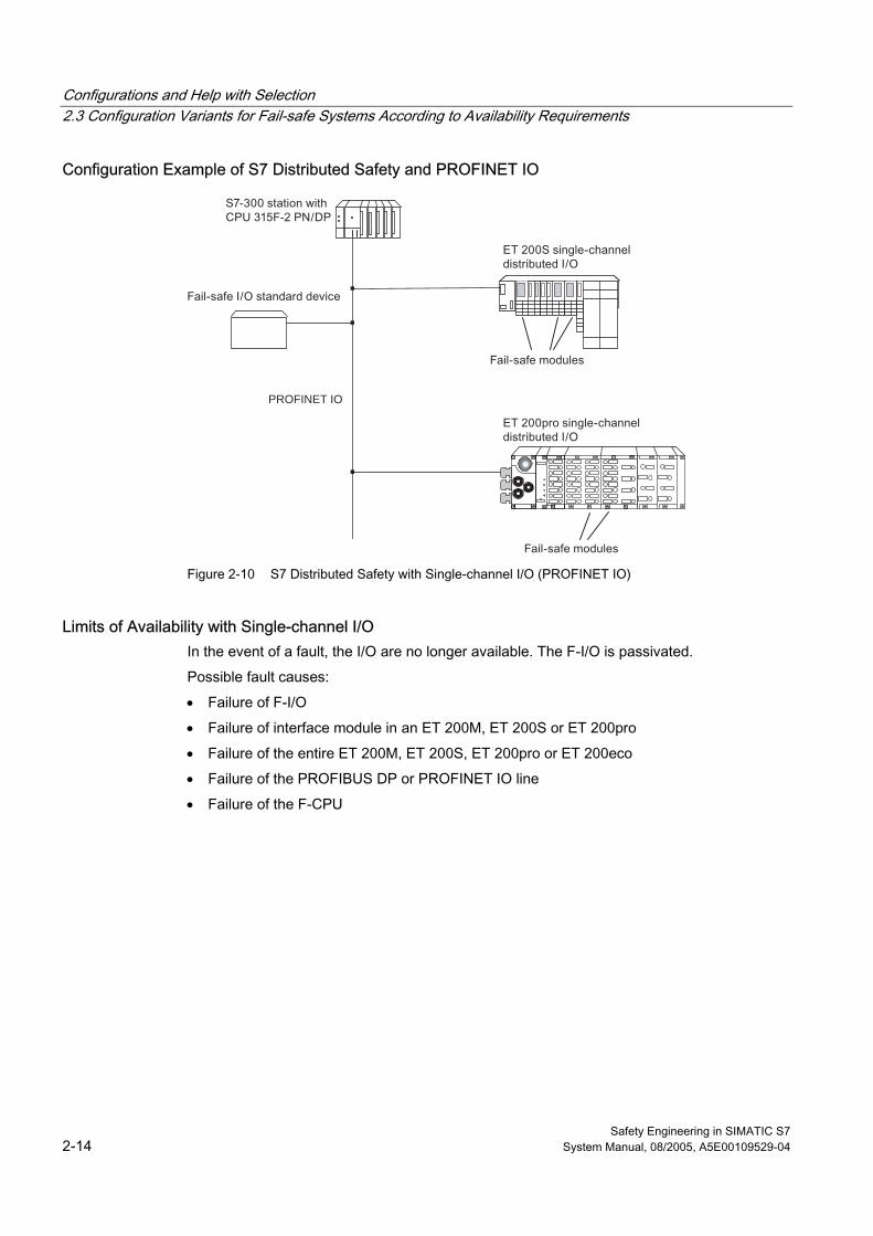
Configurations and Help with Selection 2.3 Configuration Variants for Fail-safe Systems According to Availability Requirements
Safety Engineering in SIMATIC S7 2-14 System Manual, 08/2005, A5E00109529-04
Configuration Example of S7 Distributed Safety and PROFINET IO
PROFINET IO
Figure 2-10 S7 Distributed Safety with Single-channel I/O (PROFINET IO)
Limits of Availability with Single-channel I/O In the event of a fault, the I/O are no longer available. The F-I/O is passivated.
Possible fault causes:
• Failure of F-I/O
• Failure of interface module in an ET 200M, ET 200S or ET 200pro
• Failure of the entire ET 200M, ET 200S, ET 200pro or ET 200eco
• Failure of the PROFIBUS DP or PROFINET IO line
• Failure of the F-CPU
Configurations and Help with Selection 2.3 Configuration Variants for Fail-safe Systems According to Availability Requirements
Safety Engineering in SIMATIC S7 System Manual, 08/2005, A5E00109529-04 2-15
2.3.2 Single-channel I/O (S7 F Systems)
What is single-channel I/O? In a single-channel configuration, fail-safe I/O are not redundant. The fail-safe I/O is addressed by one F-CPU.
Required Hardware Components for S7 F-Systems Which hardware components are required depends on whether PROFIBUS DP is configured with copper cable or fiber-optic cable. The F-I/O is not redundant.
S7 F Systems and PROFIBUS DP with Copper Cable The following are required to configure PROFIBUS DP with copper cable:
• One CPU 414-4H or CPU 417-4H
• One PROFIBUS DP line
• Fail-safe I/O, for example:
– One ET 200M with: IM153-2, F-SMs, and, if necessary, standard SMs, safety protector (required for SIL3/Category 4 applications only)
– One ET 200S with: IM 151-1 HIGH FEATURE, fail-safe modules, and, if necessary, ET 200S standard modules
– ET 200eco fail-safe I/O module
– Fail-safe DP standard slave
• Bus connector for connecting the F-CPU and fail-safe I/O to the PROFIBUS DP
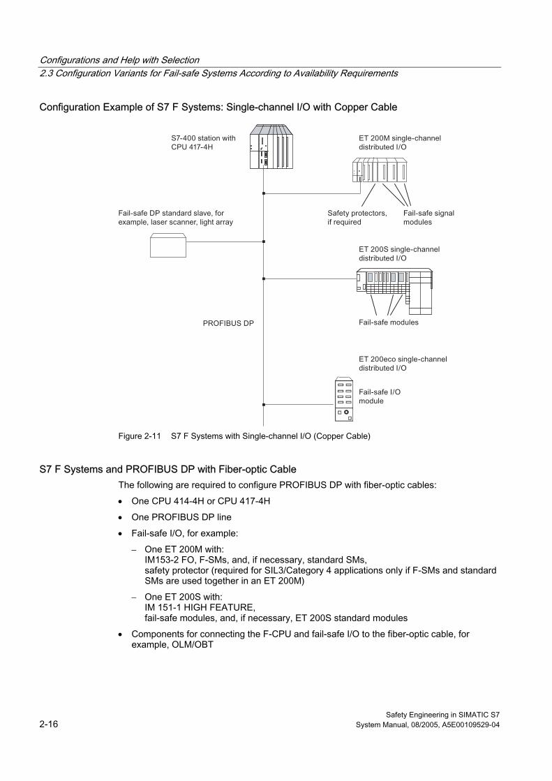
Configurations and Help with Selection 2.3 Configuration Variants for Fail-safe Systems According to Availability Requirements
Safety Engineering in SIMATIC S7 2-16 System Manual, 08/2005, A5E00109529-04
Configuration Example of S7 F Systems: Single-channel I/O with Copper Cable
Figure 2-11 S7 F Systems with Single-channel I/O (Copper Cable)
S7 F Systems and PROFIBUS DP with Fiber-optic Cable The following are required to configure PROFIBUS DP with fiber-optic cables:
• One CPU 414-4H or CPU 417-4H
• One PROFIBUS DP line
• Fail-safe I/O, for example:
– One ET 200M with: IM153-2 FO, F-SMs, and, if necessary, standard SMs, safety protector (required for SIL3/Category 4 applications only if F-SMs and standard SMs are used together in an ET 200M)
– One ET 200S with: IM 151-1 HIGH FEATURE, fail-safe modules, and, if necessary, ET 200S standard modules
• Components for connecting the F-CPU and fail-safe I/O to the fiber-optic cable, for example, OLM/OBT
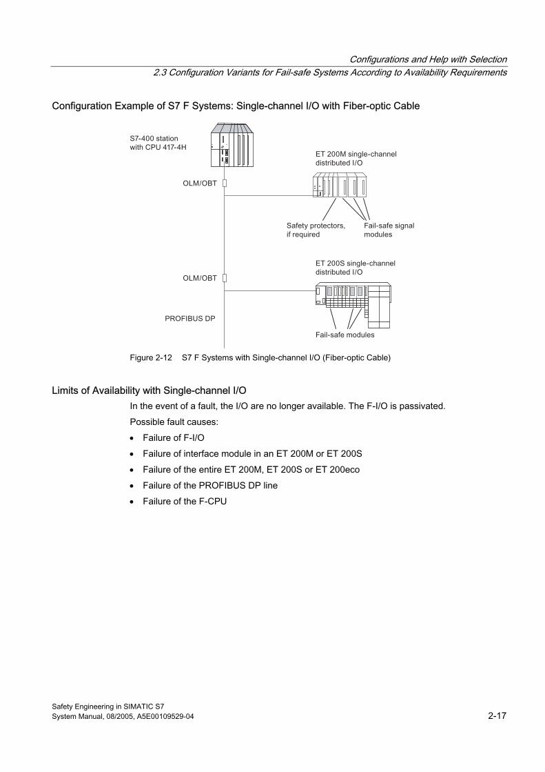
Configurations and Help with Selection 2.3 Configuration Variants for Fail-safe Systems According to Availability Requirements
Safety Engineering in SIMATIC S7 System Manual, 08/2005, A5E00109529-04 2-17
Configuration Example of S7 F Systems: Single-channel I/O with Fiber-optic Cable
Figure 2-12 S7 F Systems with Single-channel I/O (Fiber-optic Cable)
Limits of Availability with Single-channel I/O In the event of a fault, the I/O are no longer available. The F-I/O is passivated.
Possible fault causes:
• Failure of F-I/O
• Failure of interface module in an ET 200M or ET 200S
• Failure of the entire ET 200M, ET 200S or ET 200eco
• Failure of the PROFIBUS DP line
• Failure of the F-CPU
Configurations and Help with Selection 2.3 Configuration Variants for Fail-safe Systems According to Availability Requirements
Safety Engineering in SIMATIC S7 2-18 System Manual, 08/2005, A5E00109529-04
2.3.3 Single-channel Switched I/O (S7 FH Systems only)
Characteristics of Single-channel Switched I/O In a single-channel switched configuration, the F-I/O is not redundant. The F-I/O is addressed by two F-CPUs.
Only S7 FH Systems can have this configuration. F-I/O can only be used in ET 200M distributed I/O systems.
The ET 200M has a DP slave interface for each redundant PROFIBUS DP line, thus having a physical connection to both F-CPUs.
Required Hardware Components Which hardware components are required depends on whether PROFIBUS DP is configured with copper cable or fiber-optic cable.
The F-I/O is not redundant.
S7 FH Systems and PROFIBUS DP with Copper Cable The following are required to configure PROFIBUS DP with copper cable:
• Two CPU 414-4H or CPU 417-4H
• Two PROFIBUS DP lines
• One ET 200M with two (redundant) IM153-2 modules, each with a PROFIBUS DP interface
• Four bus connectors for connecting the two F-CPUs and the two IM153-2 or IM153-3 modules to PROFIBUS DP
• Non-redundant fail-safe signal modules and, if necessary, standard signal modules
• Safety protector (required for SIL3/Category 4 applications only)
S7 FH Systems and PROFIBUS DP with Fiber-optic Cable The following are required to configure PROFIBUS DP with fiber-optic cables:
• Two CPU 414-4H or CPU 417-4H
• Two PROFIBUS DP lines
• One ET 200M with two (redundant) IM153-2 FO modules, each with a PROFIBUS DP interface
• Two components for connecting the two F-CPUs to the fiber-optic cable, for example, OLM/OBT
• Non-redundant fail-safe signal modules and, if necessary, standard signal modules
• Safety protector (required for SIL3/Category 4 applications only, if
F-SMs and standard SMs are used together in an ET 200M)
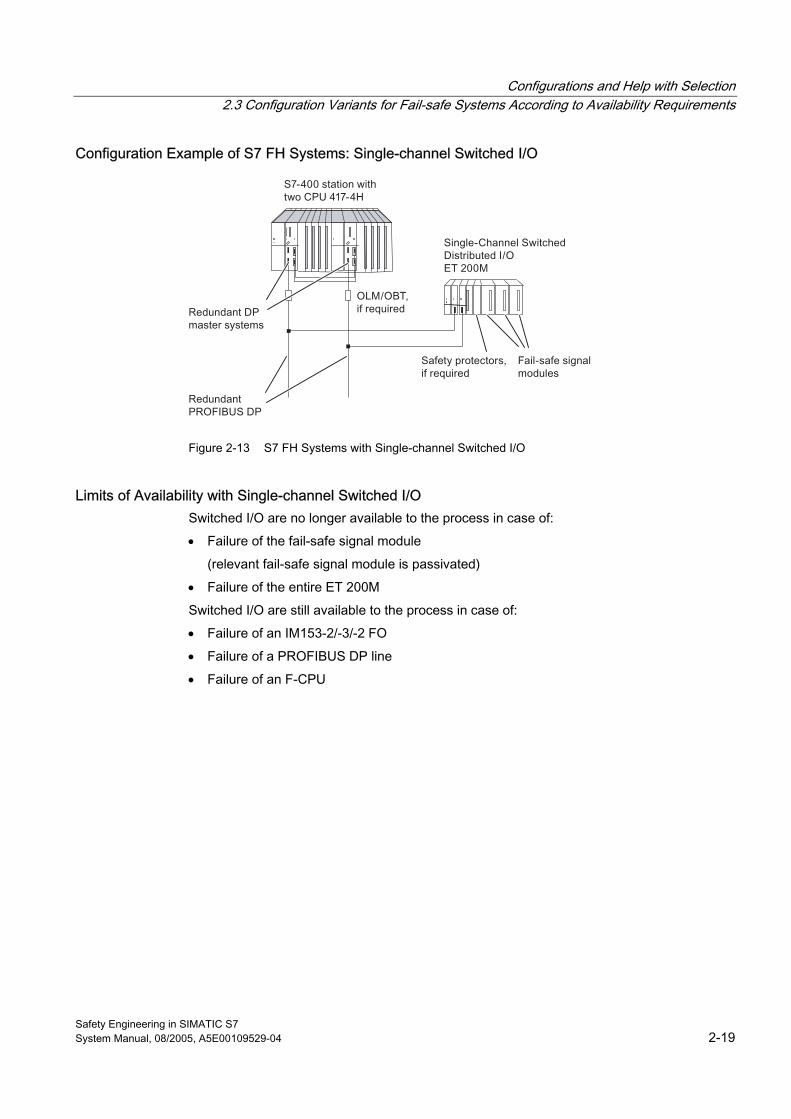
Configurations and Help with Selection 2.3 Configuration Variants for Fail-safe Systems According to Availability Requirements
Safety Engineering in SIMATIC S7 System Manual, 08/2005, A5E00109529-04 2-19
Configuration Example of S7 FH Systems: Single-channel Switched I/O
Figure 2-13 S7 FH Systems with Single-channel Switched I/O
Limits of Availability with Single-channel Switched I/O Switched I/O are no longer available to the process in case of:
• Failure of the fail-safe signal module
(relevant fail-safe signal module is passivated)
• Failure of the entire ET 200M
Switched I/O are still available to the process in case of:
• Failure of an IM153-2/-3/-2 FO
• Failure of a PROFIBUS DP line
• Failure of an F-CPU
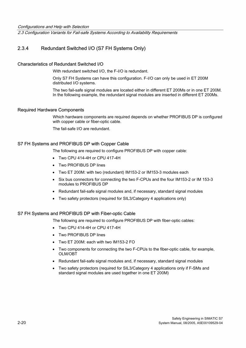
Configurations and Help with Selection 2.3 Configuration Variants for Fail-safe Systems According to Availability Requirements
Safety Engineering in SIMATIC S7 2-20 System Manual, 08/2005, A5E00109529-04
2.3.4 Redundant Switched I/O (S7 FH Systems Only)
Characteristics of Redundant Switched I/O With redundant switched I/O, the F-I/O is redundant.
Only S7 FH Systems can have this configuration. F-I/O can only be used in ET 200M distributed I/O systems.
The two fail-safe signal modules are located either in different ET 200Ms or in one ET 200M. In the following example, the redundant signal modules are inserted in different ET 200Ms.
Required Hardware Components Which hardware components are required depends on whether PROFIBUS DP is configured with copper cable or fiber-optic cable.
The fail-safe I/O are redundant.
S7 FH Systems and PROFIBUS DP with Copper Cable The following are required to configure PROFIBUS DP with copper cable:
• Two CPU 414-4H or CPU 417-4H
• Two PROFIBUS DP lines
• Two ET 200M: with two (redundant) IM153-2 or IM153-3 modules each
• Six bus connectors for connecting the two F-CPUs and the four IM153-2 or IM 153-3 modules to PROFIBUS DP
• Redundant fail-safe signal modules and, if necessary, standard signal modules
• Two safety protectors (required for SIL3/Category 4 applications only)
S7 FH Systems and PROFIBUS DP with Fiber-optic Cable The following are required to configure PROFIBUS DP with fiber-optic cables:
• Two CPU 414-4H or CPU 417-4H
• Two PROFIBUS DP lines
• Two ET 200M: each with two IM153-2 FO
• Two components for connecting the two F-CPUs to the fiber-optic cable, for example, OLM/OBT
• Redundant fail-safe signal modules and, if necessary, standard signal modules
• Two safety protectors (required for SIL3/Category 4 applications only if F-SMs and standard signal modules are used together in one ET 200M)
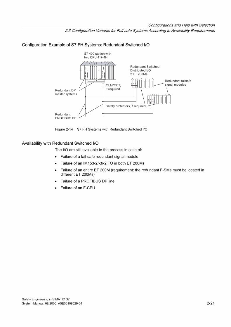
Configurations and Help with Selection 2.3 Configuration Variants for Fail-safe Systems According to Availability Requirements
Safety Engineering in SIMATIC S7 System Manual, 08/2005, A5E00109529-04 2-21
Configuration Example of S7 FH Systems: Redundant Switched I/O
Figure 2-14 S7 FH Systems with Redundant Switched I/O
Availability with Redundant Switched I/O The I/O are still available to the process in case of:
• Failure of a fail-safe redundant signal module
• Failure of an IM153-2/-3/-2 FO in both ET 200Ms
• Failure of an entire ET 200M (requirement: the redundant F-SMs must be located in different ET 200Ms)
• Failure of a PROFIBUS DP line
• Failure of an F-CPU
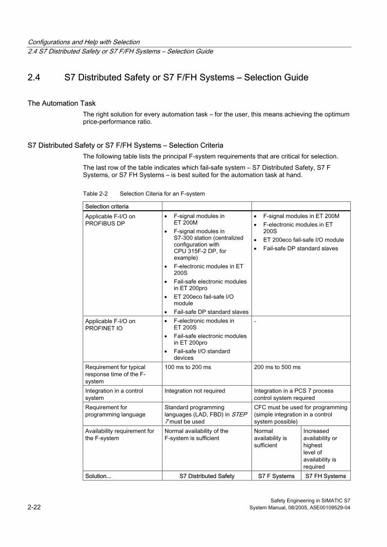
Configurations and Help with Selection 2.4 S7 Distributed Safety or S7 F/FH Systems – Selection Guide
Safety Engineering in SIMATIC S7 2-22 System Manual, 08/2005, A5E00109529-04
2.4 2.4 S7 Distributed Safety or S7 F/FH Systems – Selection Guide
The Automation Task The right solution for every automation task – for the user, this means achieving the optimum price-performance ratio.
S7 Distributed Safety or S7 F/FH Systems – Selection Criteria The following table lists the principal F-system requirements that are critical for selection.
The last row of the table indicates which fail-safe system – S7 Distributed Safety, S7 F Systems, or S7 FH Systems – is best suited for the automation task at hand.
Table 2-2 Selection Citeria for an F-system
Selection criteria Applicable F-I/O on PROFIBUS DP
• F-signal modules in ET 200M
• F-signal modules in S7-300 station (centralized configuration with CPU 315F-2 DP, for example)
• F-electronic modules in ET 200S
• Fail-safe electronic modules in ET 200pro
• ET 200eco fail-safe I/O module
• Fail-safe DP standard slaves
• F-signal modules in ET 200M • F-electronic modules in ET
200S • ET 200eco fail-safe I/O module • Fail-safe DP standard slaves
Applicable F-I/O on PROFINET IO
• F-electronic modules in ET 200S
• Fail-safe electronic modules in ET 200pro
• Fail-safe I/O standard devices
-
Requirement for typical response time of the F-system
100 ms to 200 ms 200 ms to 500 ms
Integration in a control system
Integration not required Integration in a PCS 7 process control system required
Requirement for programming language
Standard programming languages (LAD, FBD) in STEP 7 must be used
CFC must be used for programming (simple integration in a control system possible)
Availability requirement for the F-system
Normal availability of the F-system is sufficient
Normal availability is sufficient
Increased availability or highest level of availability is required
Solution... S7 Distributed Safety S7 F Systems S7 FH Systems
Configurations and Help with Selection 2.4 S7 Distributed Safety or S7 F/FH Systems – Selection Guide
Safety Engineering in SIMATIC S7 System Manual, 08/2005, A5E00109529-04 2-23
Requirements Satisfied by Both S7 Distributed Safety and S7 F/FH Systems There is no difference in the F-systems with regard to the following requirements. That is, S7 Distributed Safety and S7 F/FH Systems are equally applicable:
• Configuration is possible using copper or fiber-optic technology.
(Fiber-optic technology should be used in standard automation systems if large distances are to be spanned or if the system will be subjected to strong electromagnetic interference.)
• Safety classes SIL2/Category 3 and SIL3/Category 4 can be achieved.
System Configuration of F-System The limits for the system configuration of a fail-safe system are determined mainly by the F-CPU used. The memory configuration for all applicable F-CPUs is available in the "Memory Configuration of F-CPUs" table in "Performance Characteristics of S7 Distributed Safety and S7 F/FH Systems". Additional values are provided in the technical specifications for the F-CPU in the respective F-CPU manual.
You can find information about possible limitations for S7 FH Systems in the Automation System S7-400FH Fault-Tolerant Systems manual and in the readme file of the S7 H Systems optional package.
See also Performance Characteristics of S7 Distributed Safety and S7 F/FH Systems (Page 1-7)
S7 F Systems Fail-safe System (Page 2-5)
Configurations and Help with Selection 2.4 S7 Distributed Safety or S7 F/FH Systems – Selection Guide
Safety Engineering in SIMATIC S7 2-24 System Manual, 08/2005, A5E00109529-04
Safety Engineering in SIMATIC S7 System Manual, 08/2005, A5E00109529-04 3-1
Communication Options 33.1 3.1 Introduction
Overview This chapter presents the safety-related communication options in S7 Distributed Safety and S7 F/FH Systems and presents the similarities and differences between the two F-systems.
Additional Information Communication can take place between standard user programs exactly the same as in standard S7-300 and S7-400 automation systems and is not presented in this chapter. You will find a description in the STEP 7 manuals and in the hardware manuals for each CPU.
The user employs fail-safe blocks to some extent for safety-related communication. F-blocks and their handling are described in detail in the following references:
• For S7 Distributed Safety: S7 Distributed Safety Configuring and Programming manual
• For S7 F/FH Systems: Programmable Controllers S7 F/FH manual
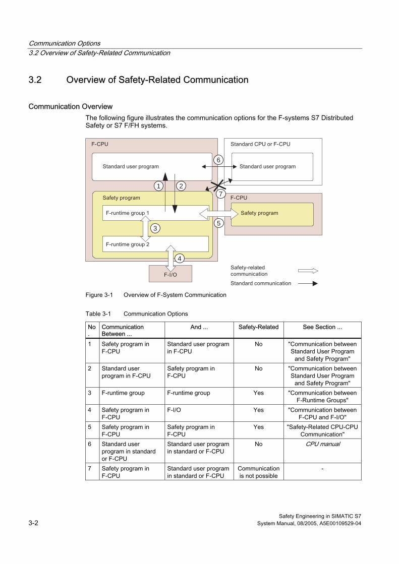
Communication Options 3.2 Overview of Safety-Related Communication
Safety Engineering in SIMATIC S7 3-2 System Manual, 08/2005, A5E00109529-04
3.2 3.2 Overview of Safety-Related Communication
Communication Overview The following figure illustrates the communication options for the F-systems S7 Distributed Safety or S7 F/FH systems.
4
6
7
53
21
Figure 3-1 Overview of F-System Communication
Table 3-1 Communication Options
No.
Communication Between ...
And ... Safety-Related See Section ...
1 Safety program in F-CPU
Standard user program in F-CPU
No "Communication between Standard User Program
and Safety Program" 2 Standard user
program in F-CPU Safety program in F-CPU
No "Communication between Standard User Program
and Safety Program" 3 F-runtime group F-runtime group Yes "Communication between
F-Runtime Groups" 4 Safety program in
F-CPU F-I/O Yes "Communication between
F-CPU and F-I/O" 5 Safety program in
F-CPU Safety program in F-CPU
Yes "Safety-Related CPU-CPU Communication"
6 Standard user program in standard or F-CPU
Standard user program in standard or F-CPU
No CPU manual
7 Safety program in F-CPU
Standard user program in standard or F-CPU
Communication is not possible
-
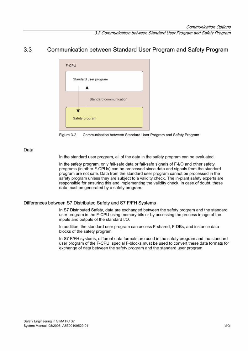
Communication Options 3.3 Communication between Standard User Program and Safety Program
Safety Engineering in SIMATIC S7 System Manual, 08/2005, A5E00109529-04 3-3
3.3 3.3 Communication between Standard User Program and Safety Program
Figure 3-2 Communication between Standard User Program and Safety Program
Data In the standard user program, all of the data in the safety program can be evaluated.
In the safety program, only fail-safe data or fail-safe signals of F-I/O and other safety programs (in other F-CPUs) can be processed since data and signals from the standard program are not safe. Data from the standard user program cannot be processed in the safety program unless they are subject to a validity check. The in-plant safety experts are responsible for ensuring this and implementing the validity check. In case of doubt, these data must be generated by a safety program.
Differences between S7 Distributed Safety and S7 F/FH Systems In S7 Distributed Safety, data are exchanged between the safety program and the standard user program in the F-CPU using memory bits or by accessing the process image of the inputs and outputs of the standard I/O.
In addition, the standard user program can access F-shared, F-DBs, and instance data blocks of the safety program.
In S7 F/FH systems, different data formats are used in the safety program and the standard user program of the F-CPU; special F-blocks must be used to convert these data formats for exchange of data between the safety program and the standard user program.
Communication Options 3.3 Communication between Standard User Program and Safety Program
Safety Engineering in SIMATIC S7 3-4 System Manual, 08/2005, A5E00109529-04
3.3.1 Communication between Standard User Program and Safety Program in S7 Distributed Safety
Data Transfer from the Safety Program to the Standard User Program The standard user program can read out all of the data in the safety program directly, since the data exist in standard format in F-DBs, instance DBs, the F-shared DB, and the process image.
Memory bits can also be written in the safety program to enable intermediate results of the safety program to be used by the standard user program without having to pass through F-data blocks. However, these memory bits are only available for processing by the standard user program and cannot be read in the safety program itself.
The process output image (PIQ) of the standard I/O can be written to, for example, for display purposes. These values cannot be read in the safety program, either.
Data Transfer from the Standard User Program to the Safety Program To process data from the standard user program in the safety program, memory bits from the standard user program or signals from the standard I/O can be read using the process input image (PII). Because these data are unsafe, the user must perform additional process-specific validity checks in the safety program to ensure that no hazardous situations can arise.
To facilitate the validity check, all signals from the standard user program that are evaluated in the safety program are included when the safety program is printed out. Addresses in the safety program that come from the standard user program are highlighted.
3.3.2 Communication between Standard User Program and Safety Program in S7 F/FH Systems
Different Data Formats The standard user program and safety program use different data formats. Safety-related F-data types are used in the safety program. Standard data types are used in the standard user program.
In an F-CPU in S7 F/FH systems, the user employs special conversion blocks for the data exchange.
Data Transfer from the Safety Program to the Standard User Program If data from the safety program are to be processed further in the standard user program, e.g., for monitoring, then an F_Fdata type_data type data conversion block must be connected between the two programs in CFC to convert F-data types to standard data types. This block can be found in the Failsafe Blocks F-library.
The F_Fdata type_data type blocks must be called in the standard user program (CFC, standard runtime group).
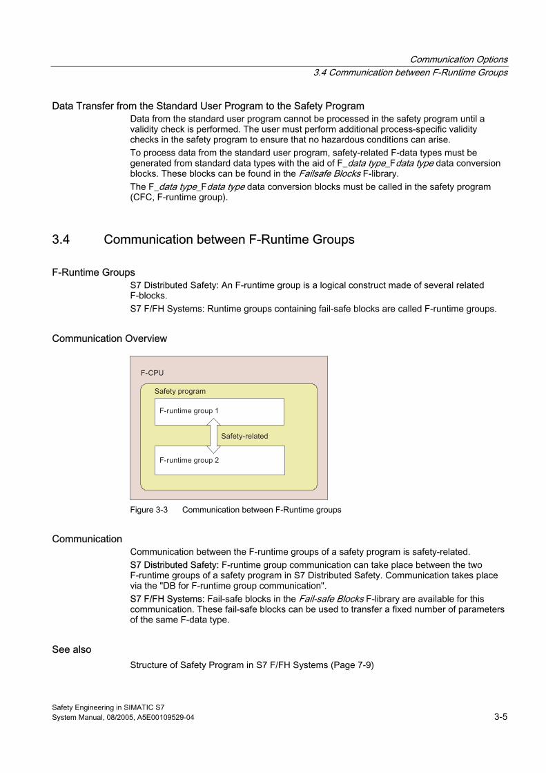
Communication Options 3.4 Communication between F-Runtime Groups
Safety Engineering in SIMATIC S7 System Manual, 08/2005, A5E00109529-04 3-5
Data Transfer from the Standard User Program to the Safety Program Data from the standard user program cannot be processed in the safety program until a validity check is performed. The user must perform additional process-specific validity checks in the safety program to ensure that no hazardous conditions can arise. To process data from the standard user program, safety-related F-data types must be generated from standard data types with the aid of F_data type_Fdata type data conversion blocks. These blocks can be found in the Failsafe Blocks F-library. The F_data type_Fdata type data conversion blocks must be called in the safety program (CFC, F-runtime group).
3.4 3.4 Communication between F-Runtime Groups
F-Runtime Groups S7 Distributed Safety: An F-runtime group is a logical construct made of several related F-blocks. S7 F/FH Systems: Runtime groups containing fail-safe blocks are called F-runtime groups.
Communication Overview
Figure 3-3 Communication between F-Runtime groups
Communication Communication between the F-runtime groups of a safety program is safety-related. S7 Distributed Safety: F-runtime group communication can take place between the two F-runtime groups of a safety program in S7 Distributed Safety. Communication takes place via the "DB for F-runtime group communication". S7 F/FH Systems: Fail-safe blocks in the Fail-safe Blocks F-library are available for this communication. These fail-safe blocks can be used to transfer a fixed number of parameters of the same F-data type.
See also Structure of Safety Program in S7 F/FH Systems (Page 7-9)
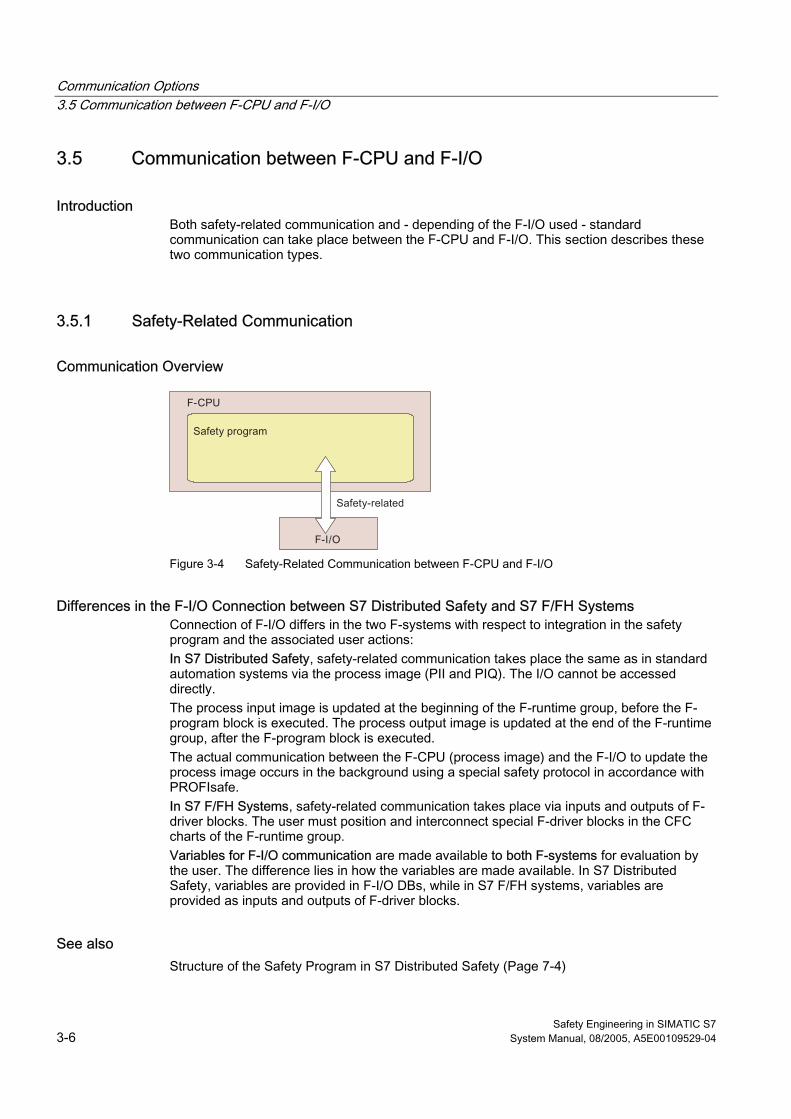
Communication Options 3.5 Communication between F-CPU and F-I/O
Safety Engineering in SIMATIC S7 3-6 System Manual, 08/2005, A5E00109529-04
3.5 3.5 Communication between F-CPU and F-I/O
Introduction Both safety-related communication and - depending of the F-I/O used - standard communication can take place between the F-CPU and F-I/O. This section describes these two communication types.
3.5.1 Safety-Related Communication
Communication Overview
Figure 3-4 Safety-Related Communication between F-CPU and F-I/O
Differences in the F-I/O Connection between S7 Distributed Safety and S7 F/FH Systems Connection of F-I/O differs in the two F-systems with respect to integration in the safety program and the associated user actions: In S7 Distributed Safety, safety-related communication takes place the same as in standard automation systems via the process image (PII and PIQ). The I/O cannot be accessed directly. The process input image is updated at the beginning of the F-runtime group, before the F-program block is executed. The process output image is updated at the end of the F-runtime group, after the F-program block is executed. The actual communication between the F-CPU (process image) and the F-I/O to update the process image occurs in the background using a special safety protocol in accordance with PROFIsafe. In S7 F/FH Systems, safety-related communication takes place via inputs and outputs of F-driver blocks. The user must position and interconnect special F-driver blocks in the CFC charts of the F-runtime group. Variables for F-I/O communication are made available to both F-systems for evaluation by the user. The difference lies in how the variables are made available. In S7 Distributed Safety, variables are provided in F-I/O DBs, while in S7 F/FH systems, variables are provided as inputs and outputs of F-driver blocks.
See also Structure of the Safety Program in S7 Distributed Safety (Page 7-4)
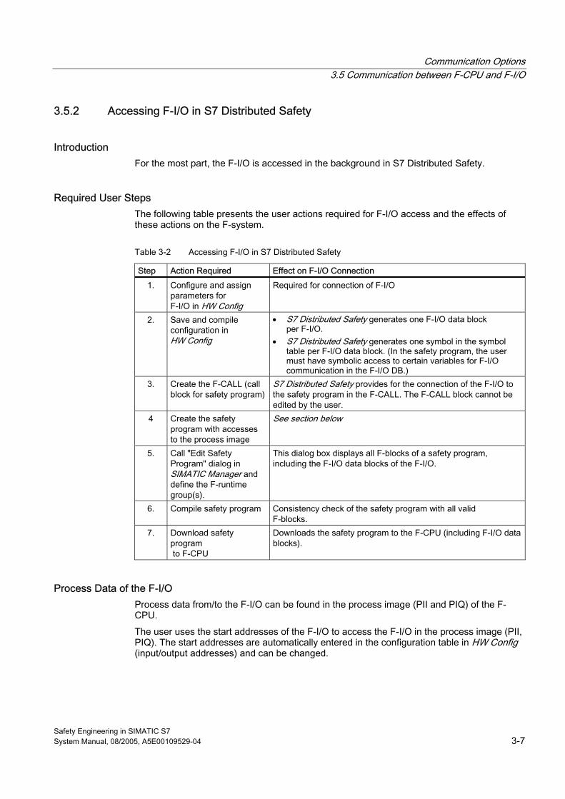
Communication Options 3.5 Communication between F-CPU and F-I/O
Safety Engineering in SIMATIC S7 System Manual, 08/2005, A5E00109529-04 3-7
3.5.2 Accessing F-I/O in S7 Distributed Safety
Introduction For the most part, the F-I/O is accessed in the background in S7 Distributed Safety.
Required User Steps The following table presents the user actions required for F-I/O access and the effects of these actions on the F-system.
Table 3-2 Accessing F-I/O in S7 Distributed Safety
Step Action Required Effect on F-I/O Connection 1. Configure and assign
parameters for F-I/O in HW Config
Required for connection of F-I/O
2. Save and compile configuration in HW Config
• S7 Distributed Safety generates one F-I/O data block per F-I/O.
• S7 Distributed Safety generates one symbol in the symbol table per F-I/O data block. (In the safety program, the user must have symbolic access to certain variables for F-I/O communication in the F-I/O DB.)
3. Create the F-CALL (call block for safety program)
S7 Distributed Safety provides for the connection of the F-I/O to the safety program in the F-CALL. The F-CALL block cannot be edited by the user.
4 Create the safety program with accesses to the process image
See section below
5. Call "Edit Safety Program" dialog in SIMATIC Manager and define the F-runtime group(s).
This dialog box displays all F-blocks of a safety program, including the F-I/O data blocks of the F-I/O.
6. Compile safety program Consistency check of the safety program with all valid F-blocks.
7. Download safety program to F-CPU
Downloads the safety program to the F-CPU (including F-I/O data blocks).
Process Data of the F-I/O Process data from/to the F-I/O can be found in the process image (PII and PIQ) of the F-CPU.
The user uses the start addresses of the F-I/O to access the F-I/O in the process image (PII, PIQ). The start addresses are automatically entered in the configuration table in HW Config (input/output addresses) and can be changed.
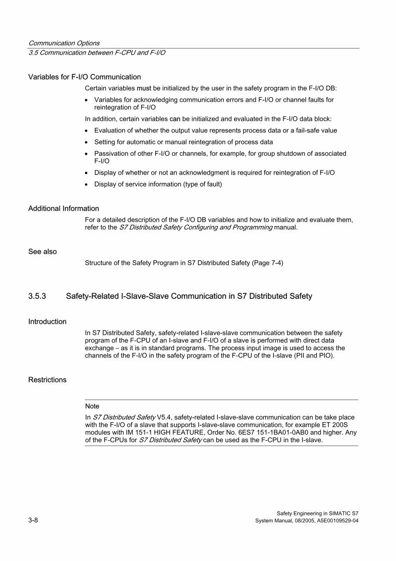
Communication Options 3.5 Communication between F-CPU and F-I/O
Safety Engineering in SIMATIC S7 3-8 System Manual, 08/2005, A5E00109529-04
Variables for F-I/O Communication Certain variables must be initialized by the user in the safety program in the F-I/O DB:
• Variables for acknowledging communication errors and F-I/O or channel faults for reintegration of F-I/O
In addition, certain variables can be initialized and evaluated in the F-I/O data block:
• Evaluation of whether the output value represents process data or a fail-safe value
• Setting for automatic or manual reintegration of process data
• Passivation of other F-I/O or channels, for example, for group shutdown of associated F-I/O
• Display of whether or not an acknowledgment is required for reintegration of F-I/O
• Display of service information (type of fault)
Additional Information For a detailed description of the F-I/O DB variables and how to initialize and evaluate them, refer to the S7 Distributed Safety Configuring and Programming manual.
See also Structure of the Safety Program in S7 Distributed Safety (Page 7-4)
3.5.3 Safety-Related I-Slave-Slave Communication in S7 Distributed Safety
Introduction In S7 Distributed Safety, safety-related I-slave-slave communication between the safety program of the F-CPU of an I-slave and F-I/O of a slave is performed with direct data exchange – as it is in standard programs. The process input image is used to access the channels of the F-I/O in the safety program of the F-CPU of the I-slave (PII and PIO).
Restrictions
Note In S7 Distributed Safety V5.4, safety-related I-slave-slave communication can be take place with the F-I/O of a slave that supports I-slave-slave communication, for example ET 200S modules with IM 151-1 HIGH FEATURE, Order No. 6ES7 151-1BA01-0AB0 and higher. Any of the F-CPUs for S7 Distributed Safety can be used as the F-CPU in the I-slave.
Communication Options 3.5 Communication between F-CPU and F-I/O
Safety Engineering in SIMATIC S7 System Manual, 08/2005, A5E00109529-04 3-9
Communication Overview
Figure 3-5 S7 Distributed Safety: Safety-related I-Slave-Slave Communication
I-Slave-Slave Communication In safety-related I-slave-slave communication, F-I/O are accessed the same as standard I/O using the process image (PII and PIO). The I/O cannot be accessed directly. The channels of an F-I/O can only be accessed from one F-runtime group.
Required User Steps The user performs the following steps for safety-related I-slave-slave communication:
1. Configure I-slave and slave in HW Config.
2. Configure the DP master system in HW Config.
3. Connect the I-slave to the slave.
4. Set the address areas for data exchange in HW Config in the "Object Properties" dialog of the I-slave.
5. Once the safety program has been created, generate and download it to the F-CPU of the I-slave.
Further Information For detailed information on configuring safety-related I-slave-slave communication, refer to the S7 Distributed Safety Configuring and Programming manual.
Communication Options 3.5 Communication between F-CPU and F-I/O
Safety Engineering in SIMATIC S7 3-10 System Manual, 08/2005, A5E00109529-04
3.5.4 Accessing F-I/O in S7 F/FH Systems
Access via F-Driver Blocks In S7 F/FH Systems, the F-I/O is accessed via F-driver blocks, which must be positioned and interconnected by the user in some cases. One F-module driver per F-I/O and one F-channel driver for each F-I/O input and output channel used are required.
F-Module Driver The F-module driver takes over the PROFIsafe communication between the safety program and the F-I/O. It is automatically positioned and interconnected in the safety program.
F-Channel Drivers F-channel drivers provide process data in a safe data format. They must be positioned and interconnected in the safety program by the user.
Required User Steps The user must perform the following steps to connect the F-I/O:
1. Select appropriate F-channel drivers from the Failsafe Blocks F-library and position them in the safety program.
2. Interconnect the F-channel drivers.
3. Once the safety program has been created, compile and download it to the F-CPU.
Process Data of the F-I/O Process data can be found as follows:
• Process data from the F-I/O (input channels), at an output of the associated F-channel driver
• Process data to the F-I/O (output channels), at an input of the associated F-channel driver
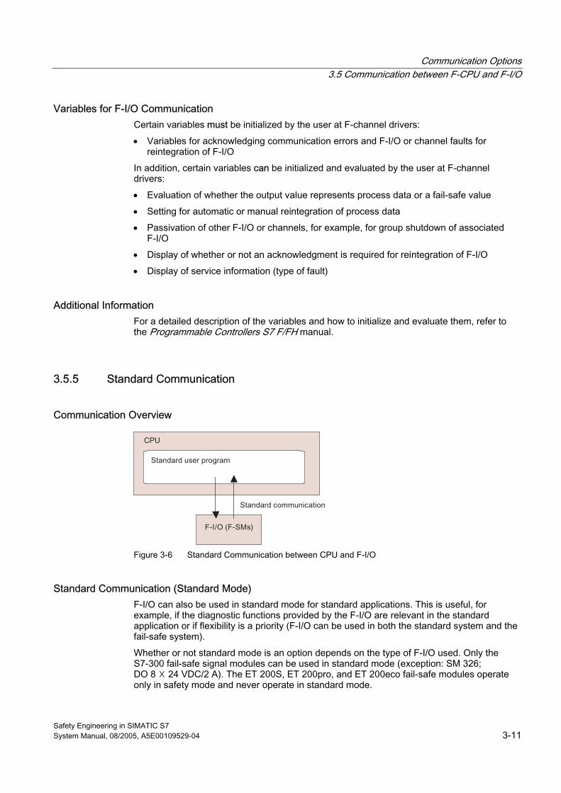
Communication Options 3.5 Communication between F-CPU and F-I/O
Safety Engineering in SIMATIC S7 System Manual, 08/2005, A5E00109529-04 3-11
Variables for F-I/O Communication Certain variables must be initialized by the user at F-channel drivers:
• Variables for acknowledging communication errors and F-I/O or channel faults for reintegration of F-I/O
In addition, certain variables can be initialized and evaluated by the user at F-channel drivers:
• Evaluation of whether the output value represents process data or a fail-safe value
• Setting for automatic or manual reintegration of process data
• Passivation of other F-I/O or channels, for example, for group shutdown of associated F-I/O
• Display of whether or not an acknowledgment is required for reintegration of F-I/O
• Display of service information (type of fault)
Additional Information For a detailed description of the variables and how to initialize and evaluate them, refer to the Programmable Controllers S7 F/FH manual.
3.5.5 Standard Communication
Communication Overview
Figure 3-6 Standard Communication between CPU and F-I/O
Standard Communication (Standard Mode) F-I/O can also be used in standard mode for standard applications. This is useful, for example, if the diagnostic functions provided by the F-I/O are relevant in the standard application or if flexibility is a priority (F-I/O can be used in both the standard system and the fail-safe system).
Whether or not standard mode is an option depends on the type of F-I/O used. Only the S7-300 fail-safe signal modules can be used in standard mode (exception: SM 326; DO 8 ☓ 24 VDC/2 A). The ET 200S, ET 200pro, and ET 200eco fail-safe modules operate only in safety mode and never operate in standard mode.
Communication Options 3.5 Communication between F-CPU and F-I/O
Safety Engineering in SIMATIC S7 3-12 System Manual, 08/2005, A5E00109529-04
Mechanisms in Standard Mode The mechanisms commonly used in standard automation systems can be used for standard operation between the CPU and S7-300 fail-safe signal modules. These include:
• Direct access
• Access via the process image
• In CFC, access via channel drivers of the PCS 7 Drivers library (S7 F/FH Systems only)
• Reading out diagnostic data records
Reading Out Diagnostic Data as in Standard Mode Diagnostic information from fail-safe signal modules ET 200S and ET 200pro, and the ET 200eco fail-safe I/O module is not relevant for safety. As in standard mode, diagnostic data record transfers are used to transfer this information to the F-CPU and enter it in the diagnostic buffer of the F-CPU and F-SMs acyclically.
Diagnostic data can be read out by the user with STEP 7 as follows:
• From the diagnostic buffer of the F-CPU and F-SMs
• As slave diagnostics of the ET 200S, ET 200pro and ET 200eco fail-safe modules
• In the standard user program with SFC 59 (F-SMs only)
Reading Out Diagnostic Data in Safety Mode of F-SMs When F-SMs are operated in safety mode, the diagnostic data records of the F-SMs can also be read out to the standard user program with SFC 59.
Additional special module diagnostic blocks are available for S7 F/FH systems for this purpose. These blocks automatically generate messages, for example, to WinCC, and are used mainly in conjunction with PCS 7 (see Programmable Controllers S7 F/FH manual).
Communication Options 3.6 Safety-Related CPU-CPU Communication
Safety Engineering in SIMATIC S7 System Manual, 08/2005, A5E00109529-04 3-13
3.6 3.6 Safety-Related CPU-CPU Communication
Introduction Both S7 Distributed Safety and S7 F/FH Systems allow safety-related communication between safety programs in different F-CPUs. However, the communication mechanisms for each are different:
Table 3-3 Overview of Communication between F-CPUs
F-System Communication via ... Communication between ...
PROFIBUS DP DP master/DP master
PROFIBUS DP DP-master/I-slave
PROFIBUS DP I-slave/I-slave
PROFINET IO I/O Controller / I/O Devices
S7 Distributed Safety
Industrial Ethernet (configured S7 connections)
Not relevant
S7 F/FH Systems Via PROFIBUS, MPI, Industrial Ethernet, etc: Configured standard or fault-tolerant S7 connections
Not relevant
3.6.1 S7 Distributed Safety: Safety-related Master-Master Communication
DP/DP Coupler In S7 Distributed Safety, a DP/DP coupler (order number 6ES7 158-0AD01-0XA0) must be used for safety-related communication between safety programs in different F-CPUs (DP masters).
Each F-CPU is linked to the DP/DP coupler via its PROFIBUS DP interface.
Communication Options 3.6 Safety-Related CPU-CPU Communication
Safety Engineering in SIMATIC S7 3-14 System Manual, 08/2005, A5E00109529-04
Communication Overview
Figure 3-7 S7 Distributed Safety: Safety-related master-master communication
Master-Master Communication Safety-related communication takes place with the aid of two fail-safe application blocks: the F_SENDDP block for sending data and the F_RCVDP block for receiving data. These blocks are called by the user in the respective safety program of the F-CPU. They can be used to transfer a fixed number of fail-safe data of data types BOOL and INT in a fail-safe manner.
Required User Steps The user performs the following steps for safety-related master-master communication:
1. Set up hardware with a DP/DP coupler
2. Configure the DP/DP coupler in HW Config
3. Call F_SENDDP and F_RCVDP from the Distributed Safety F-library in the safety program of the respective F-CPU
4. Assign parameters for F_SENDDPs and F_RCVDPs
5. Once the safety programs have been created, compile and download them to the appropriate F-CPU
Additional Information For information on the DP/DP coupler, refer to the documentation for the DP/DP coupler and the SIMATIC NET, PROFIBUS Networks manual. For detailed information on configuring and programming safety-related
master-master communication, refer to the S7 Distributed Safety Configuring and Programming manual.
See also Structure of the Safety Program in S7 Distributed Safety (Page 7-4)
Communication Options 3.6 Safety-Related CPU-CPU Communication
Safety Engineering in SIMATIC S7 System Manual, 08/2005, A5E00109529-04 3-15
3.6.2 S7 Distributed Safety: Safety-related Master-I-Slave Communication
Introduction In S7 Distributed Safety, safety-related CPU-CPU communication between the safety program of the F-CPU for the DP master and the safety program(s) of the F-CPU(s) for one or more I-slaves takes place over master-slave connections, as in standard systems.
Communication Overview
Figure 3-8 S7 Distributed Safety: Safety-related master-I-slave communication
Master-I-Slave Communication Safety-related communication takes place with the aid of two fail-safe application blocks: the F_SENDDP block for sending data and the F_RCVDP block for receiving data. These blocks are called by the user in the respective safety program of the F-CPU. They can be used to transfer a fixed number of fail-safe data of data types BOOL and INT in a fail-safe manner.
Required User Steps The user should carry out the following steps for safety-related master-I-slave communication:
1. Configure I-slave in HW Config
2. Configure the DP master system in HW Config
3. Connect the I-slave to the DP master
4. Set the address areas for data exchange in HW Config
5. Call F_SENDDP and F_RCVDP from the Distributed Safety F-library in the safety programs of the F-CPU for the DP master and I-slave
6. Assign parameters for F_SENDDPs and F_RCVDPs
7. Once the safety programs have been created, compile and download them to the appropriate F-CPU.
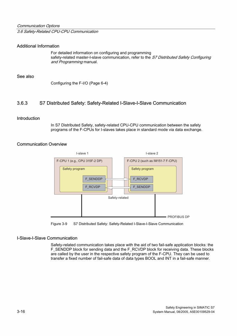
Communication Options 3.6 Safety-Related CPU-CPU Communication
Safety Engineering in SIMATIC S7 3-16 System Manual, 08/2005, A5E00109529-04
Additional Information For detailed information on configuring and programming safety-related master-I-slave communication, refer to the S7 Distributed Safety Configuring and Programming manual.
See also Configuring the F-I/O (Page 6-4)
3.6.3 S7 Distributed Safety: Safety-Related I-Slave-I-Slave Communication
Introduction In S7 Distributed Safety, safety-related CPU-CPU communication between the safety programs of the F-CPUs for I-slaves takes place in standard mode via data exchange.
Communication Overview
Figure 3-9 S7 Distributed Safety: Safety-Related I-Slave-I-Slave Communication
I-Slave-I-Slave Communication Safety-related communication takes place with the aid of two fail-safe application blocks: the F_SENDDP block for sending data and the F_RCVDP block for receiving data. These blocks are called by the user in the respective safety program of the F-CPU. They can be used to transfer a fixed number of fail-safe data of data types BOOL and INT in a fail-safe manner.
Communication Options 3.6 Safety-Related CPU-CPU Communication
Safety Engineering in SIMATIC S7 System Manual, 08/2005, A5E00109529-04 3-17
Required User Steps The user performs the following steps for safety-related I-slave-I-slave communication:
1. Configure I-slaves in HW Config
2. Configure the DP master system in HW Config
3. Connect the I-slaves to the DP master
4. Set the address areas for data exchange in HW Config
5. Call F_SENDDP and F_RCVDP from the Distributed Safety F-library in the safety programs of the F-CPUs for the relevant I-slaves
6. Assign parameters for F_SENDDPs and F_RCVDPs
7. Once the safety programs have been created, compile and download them to the appropriate F-CPU
Additional Information For detailed information on configuring and programming safety-related I-slave-I-slave communication, refer to the S7 Distributed Safety Configuring and Programming manual.
See also Configuring the F-I/O (Page 6-4)
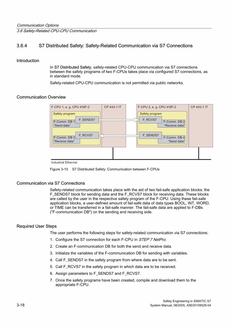
Communication Options 3.6 Safety-Related CPU-CPU Communication
Safety Engineering in SIMATIC S7 3-18 System Manual, 08/2005, A5E00109529-04
3.6.4 S7 Distributed Safety: Safety-Related Communication via S7 Connections
Introduction In S7 Distributed Safety, safety-related CPU-CPU communication via S7 connections between the safety programs of two F-CPUs takes place via configured S7 connections, as in standard mode.
Safety-related CPU-CPU communication is not permitted via public networks.
Communication Overview
Figure 3-10 S7 Distributed Safety: Communication between F-CPUs
Communication via S7 Connections Safety-related communication takes place with the aid of two fail-safe application blocks: the F_SENDS7 block for sending data and the F_RCVS7 block for receiving data. These blocks are called by the user in the respective safety program of the F-CPU. Using these fail-safe application blocks, a user-defined amount of fail-safe data of data types BOOL, INT, WORD, or TIME can be transferred in a fail-safe manner. The fail-safe data are applied to F-DBs ("F-communication DB") on the sending and receiving side.
Required User Steps The user performs the following steps for safety-related communication via S7 connections:
1. Configure the S7 connection for each F-CPU in STEP 7 NetPro.
2. Create an F-communication DB for both the send and receive data.
3. Initialize the variables of the F-communication DB for sending with variables.
4. Call F_SENDS7 in the safety program from where data are to be sent.
5. Call F_RCVS7 in the safety program in which data are to be received.
6. Assign parameters to F_SENDS7 and F_RCVS7.
7. Once the safety programs have been created, compile and download them to the appropriate F-CPU.
Communication Options 3.6 Safety-Related CPU-CPU Communication
Safety Engineering in SIMATIC S7 System Manual, 08/2005, A5E00109529-04 3-19
Limitations for S7 Distributed Safety
Note In Distributed Safety, S7 connections are generally allowed via Industrial Ethernet only!
Safety-related communication via S7 connections can take place to and from the following CPUs: • CPU 315F-2 PN/DP (only via PN interface of the CPU) • CPU 317F-2 PN/DP (only via PN interface of the CPU) • CPU 416F-2 as of firmware version V 4.0
Additional Information You can find information on configuring S7 connections in the STEP 7 online help.
For detailed information on configuring and programming safety-related communication via S7 connections, refer to the S7 Distributed Safety Configuring and Programming manual.
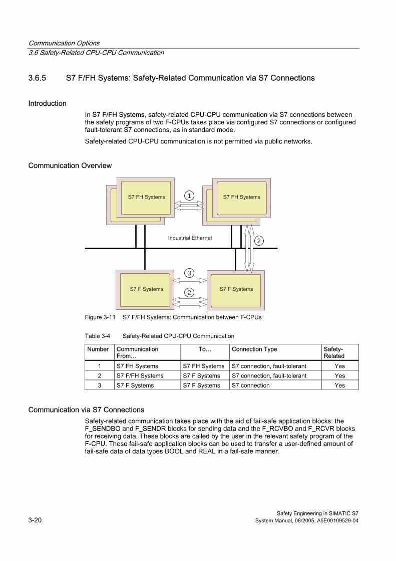
Communication Options 3.6 Safety-Related CPU-CPU Communication
Safety Engineering in SIMATIC S7 3-20 System Manual, 08/2005, A5E00109529-04
3.6.5 S7 F/FH Systems: Safety-Related Communication via S7 Connections
Introduction In S7 F/FH Systems, safety-related CPU-CPU communication via S7 connections between the safety programs of two F-CPUs takes place via configured S7 connections or configured fault-tolerant S7 connections, as in standard mode.
Safety-related CPU-CPU communication is not permitted via public networks.
Communication Overview
1
2
2
3
Figure 3-11 S7 F/FH Systems: Communication between F-CPUs
Table 3-4 Safety-Related CPU-CPU Communication
Number Communication From…
To… Connection Type Safety-Related
1 S7 FH Systems S7 FH Systems S7 connection, fault-tolerant Yes 2 S7 F/FH Systems S7 F Systems S7 connection, fault-tolerant Yes 3 S7 F Systems S7 F Systems S7 connection Yes
Communication via S7 Connections Safety-related communication takes place with the aid of fail-safe application blocks: the F_SENDBO and F_SENDR blocks for sending data and the F_RCVBO and F_RCVR blocks for receiving data. These blocks are called by the user in the relevant safety program of the F-CPU. These fail-safe application blocks can be used to transfer a user-defined amount of fail-safe data of data types BOOL and REAL in a fail-safe manner.
Communication Options 3.6 Safety-Related CPU-CPU Communication
Safety Engineering in SIMATIC S7 System Manual, 08/2005, A5E00109529-04 3-21
Required User Steps The user performs the following steps for safety-related communication via S7 connections:
1. Configure the S7 connection for each F-CPU in STEP 7.
2. In the safety program of the respective F-CPU, select fail-safe blocks for CPU-CPU communication from the Fail-safe Blocks F-library and then interconnect and assign parameters for them.
3. Once the safety programs have been created, compile and download them to the appropriate F-CPU.
Additional Information You can find information on configuring the possible connection types in the STEP 7 online help.
For detailed information on configuring and programming safety-related communication via S7 connections, refer to the Programmable Controllers S7 F/FH manual.
See also Structure of Safety Program in S7 F/FH Systems (Page 7-9)

Communication Options 3.6 Safety-Related CPU-CPU Communication
Safety Engineering in SIMATIC S7 3-22 System Manual, 08/2005, A5E00109529-04
Safety Engineering in SIMATIC S7 System Manual, 08/2005, A5E00109529-04 4-1
Safety in F-Systems 44.1 4.1 Introduction
Overview The safety mechanisms in S7 Distributed Safety and S7 F/FH Systems F-systems are essentially the same. Safety mechanisms visible to the user are presented in this chapter, including:
• Safety mode
• Fault reactions
• Restart of F-system
• Password protection for F-systems
Differences between S7 Distributed Safety and S7 F/FH Systems are individually noted.
An overview of the standards, approvals, and safety requirements met by S7 Distributed Safety and S7 F/FH Systems is presented in "Standards and Approvals."
Additional Information The configuring and programming manuals for S7 Distributed Safety and S7 F/FH systems present information on working with the safety mechanisms and provide more detailed information, where applicable.
Standard behavior is described in the STEP 7 manuals and hardware manuals and is not covered in this manual.
Safety in F-Systems 4.1 Introduction
Safety Engineering in SIMATIC S7 4-2 System Manual, 08/2005, A5E00109529-04
Safety in F-Systems
Warning S7 Distributed Safety and S7 F/FH Systems F-systems are used to control processes that can achieve a safe state immediately as a result of a shutdown.
S7 Distributed Safety and S7 F/FH Systems can only be used for controlling processes in which an immediate shutdown does not pose a danger to persons or the environment.
Safety in F-systems is guaranteed through the following:
• Integrated safety functions for fault detection and fault reaction
• F-system access protection
Safety Functions The safety functions for fault detection and fault reaction are contained mainly in the safety program and the F-I/O. These functions are implemented by suitable fail-safe blocks and supported by the hardware and operating system of the F-CPU.
Access Protection Access to F-systems is protected by assigning passwords for the F-CPU and the safety program. Access protection is described in more detail in the following manuals:
• For S7 Distributed Safety: S7 Distributed Safety Configuring and Programming manual
• For S7 F/FH Systems: Programmable Controllers S7 F/FH manual
Warning
To protect against unauthorized F-system hardware modifications, appropriate measures must be taken, such as: • Installation in a locked cabinet • Using an adhesive label to protect the Micro Memory card or Flash card of the F-CPU
See also Standards and Approvals (Page 4-8)
Safety Requirements (Page 4-12)
Safety in F-Systems 4.2 Safety Mode
Safety Engineering in SIMATIC S7 System Manual, 08/2005, A5E00109529-04 4-3
4.2 4.2 Safety Mode
Safety Mode In safety mode, the safety functions for fault detection and fault reaction are activated in the following:
• Fail-safe I/O
• Safety program of the F-CPU
Safety Mode of F-I/O For S7-300 fail-safe signal modules, the "Safety mode" parameter setting in HW Config determines whether the modules are operated in standard mode (used as S7-300 standard signal modules except for SM 326; DO 8 ☓ 24 VDC/2 A) or in safety mode.
ET 200S, ET 200pro and ET 200eco fail-safe modules can only be used in safety mode.
Safety Mode of Safety Program The safety program runs in the F-CPU in safety mode. This means that all safety mechanisms for fault detection and fault reaction are activated. The safety program cannot be modified during operation in safety mode.
Safety mode of the safety program in the F-CPU can be deactivated and reactivated occasionally. So-called "deactivated safety mode" enables the safety program to be tested online and changed as needed while the F-CPU is in RUN mode.
For S7 Distributed Safety, you can switch back to safety mode only after an operating mode change from RUN to STOP to RUN.
For S7 F/FH systems, an operating mode change is not needed to return to safety mode.
Safety Message Frame In safety mode, data are transmitted consistently between the F-CPU and F-I/O in a safety message frame. The safety message frame in accordance with PROFIsafe consists of the following:
• Process data (user data)
• Status byte/control byte (coordination data for safety mode)
• Sequence number
• CRC signature
Safety-related CPU-CPU communication also takes place using a safety message frame similar to PROFIsafe. The following information on monitoring time, sequence number, and CRC signature is also applicable.
Safety in F-Systems 4.2 Safety Mode
Safety Engineering in SIMATIC S7 4-4 System Manual, 08/2005, A5E00109529-04
Monitoring Time and Sequence Number The F-CPU assigns a sequence number to the F-I/O for time monitoring of the message frame update in the PROFIsafe protocol.
A valid, current safety message frame with a valid sequence number must be received by the F-CPU and the F-I/O within an assignable monitoring time.
If a valid sequence number is not detected within the monitoring time, the F-I/O is passivated.
CRC (Cyclic Redundancy Check) Signature A CRC signature contained in the safety message frame protects the validity of the process data in the safety message frame, the accuracy of the assigned address references, and the safety-relevant parameters.
If a CRC signature error occurs during communication between the F-CPU and F-I/O, e.g., due to intermittent electromagnetic interference, the F-I/O is passivated.
See also Introduction (Page 3-13)
Fault Reactions (Page 4-5)
Configuring the Monitoring Times (Page A-2)
Safety in F-Systems 4.3 Fault Reactions
Safety Engineering in SIMATIC S7 System Manual, 08/2005, A5E00109529-04 4-5
4.3 4.3 Fault Reactions
Safe State The basic principle behind the safety concept is the existence of a safe state for all process variables. For digital F-I/O, this is the value "0", for example. This applies to both sensors and actuators.
Fault Reactions in the F-CPU and Operating System The F-CPU and the operating system react to faults in S7 Distributed Safety and S7 F/FH Systems the same way as in standard S7-300 and S7-400 systems. In addition, fault reactions are triggered in the safety program in F-systems.
Fault Reactions in the Safety Program All of the fault reactions in the safety program cause the process variables to go to a safe state. Specifically, the fault reactions are: • S7 Distributed Safety: F-CPU goes to STOP mode.
This state can only be overridden by restarting the F-system. • S7 F/FH Systems:Complete shutdown of safety program or, alternatively, shutdown of
faulty F-run-time group using the F_SHUTDN F-block. The F-CPU does not go to STOP mode. The standard user program is not affected by the shutdown. Once faults are eliminated, the safety program or F-run-time group must be restarted. This restart is implemented after user acknowledgment in the F_SHUTDN block.
• Passivation of F-I/O/Channels of an F-I/O. I/O faults or communication errors cause the affected F-I/O or channels of the F-I/O to be passivated; the F-CPU does not go to STOP mode. Once faults are eliminated, the F-I/O or channels of the F-I/O must be reintegrated (depassivation). Reintegration (switchover from fail-safe values to process data) occurs automatically or, alternatively, after mandatory acknowledgment by the user.
Standard diagnostic and message functions can also be implemented in response to a detected fault. In S7 FH Systems, a master-reserve switchover is triggered when the master goes to STOP mode.
Fault Reactions in F-I/O If an F-I/O detects a fault, it switches the relevant channel or all channels to the safe state. That is, the channels of this F-I/O are passivated. The F-I/O signals the detected fault to the F-CPU. In addition, the fault is signaled to the safety program in the F-CPU via a safety message frame. Once the fault is eliminated, the F-I/O must be reintegrated (depassivation) (see "Fault Reactions in Safety Program").
See also Standard Communication (Page 3-11)
Restart of F-System (Page 4-6)
Safety in F-Systems 4.4 Restart of F-System
Safety Engineering in SIMATIC S7 4-6 System Manual, 08/2005, A5E00109529-04
4.4 4.4 Restart of F-System
F-System Operating Modes The operating modes of S7 Distributed Safety and S7 F/FH Systems differ from those of standard systems only in terms of the restart characteristics and the behavior in HOLD mode.
Restart Characteristics When an F-CPU is switched from STOP to RUN mode, the standard user program restarts in the usual way. When the safety program is restarted, the following data blocks are initialized with values from the load memory:
• For S7 Distributed Safety: all data blocks with the F-attribute
• For S7 F/FH Systems: all data blocks
This occurs analogously to a cold restart. As a result, saved error information is lost.
The F-system automatically reintegrates the F-I/O. In contrast to the standard user program, restart OBs (OB 100 to OB 102) cannot be used in the safety program.
Restart Protection A data handling error or an internal fault can also trigger a safety program restart with the values from the load memory. If your process does not allow such a startup, you must program a restart/startup protection in the safety program: Process data outputs must be blocked until manually enabled. The process data output block must not be released until it is safe to do so and faults have been corrected.
HOLD Mode HOLD mode is not supported for S7 Distributed Safety and S7 F/FH Systems. If a HOLD request stops execution of the user program, this state can only be overridden by a restart (cold restart or warm restart).
Safety in F-Systems 4.5 Password Protection for F-Systems
Safety Engineering in SIMATIC S7 System Manual, 08/2005, A5E00109529-04 4-7
4.5 4.5 Password Protection for F-Systems
Two Passwords In addition to the standard password for the F-CPU or CPU, F-systems require a password for the safety program.
The password for the F-CPU protects the F-systems from unauthorized downloads to the F-CPU from the engineering system (ES) or programming device (PG).
The password for the safety program protects from unauthorized changes to the configuration and parameter settings of the F-CPU and F-I/O.
Assigning Passwords The user assigns the password for the F-CPU in the "Protection" tab in HW Config when assigning parameters for the F-CPU.
The user assigns the password for the safety program when programming/configuring the safety program. Accordingly, a dialog box is displayed automatically when the safety program is compiled the first time.
4.6 4.6 Acceptance Test of System
Who Performs the Acceptance Test? As a general rule, the acceptance test is performed by independent experts.
Support when Preparing for Acceptance Test When a system undergoes an acceptance test, all standards relevant to the specific application must be checked for compliance.
The following special STEP 7functions are available in SIMATIC Manager to aid the user in checking for proper use of the F-system:
• Compare safety programs
• Print safety programs
All data relevant to the acceptance test of the F-system can be accessed in SIMATIC Manager and printed as needed.
User Actions Actions that are undertaken by the user to prepare the system for the acceptance test depend on the F-system that is used. For this reason, the procedures are described in the relevant configuring and programming manuals for S7 Distributed Safety and S7 F/FH systems under "System Acceptance Test."
Safety in F-Systems 4.7 Standards and Approvals
Safety Engineering in SIMATIC S7 4-8 System Manual, 08/2005, A5E00109529-04
4.7 4.7 Standards and Approvals
Safety Certificate Copies of the Safety Certificate (TÜV Certificate) for the fail-safe components of S7 Distributed Safety and S7 F/FH Systems as well as the Report on the Certificate and Annex 1 of the Report on the Certificate
"Safety-Related Programmable System SIMATIC S7 Distributed Safety" and
"Safety-Related Programmable Systems SIMATIC S7 F/FH Systems (formerly S7-400F and S7-400FH)" are available upon request from:
Ms. Petra Bleicher A&D AS RD ST Type Test Fax No. 49 9621 80 3146 e-mail: [email protected]
Note Annex 1 of the Report on the Certificate contains permissible version numbers and signatures for fail-safe components of S7 Distributed Safety and S7 F/FH Systems that are required to be checked during an acceptance test.
The Report on the Certificate contains the current requirements that must be met when S7 Distributed Safety or S7 F/FH Systems are used.
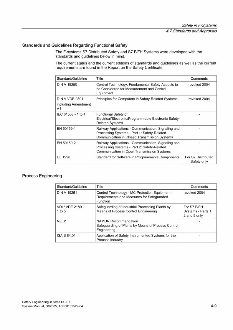
Safety in F-Systems 4.7 Standards and Approvals
Safety Engineering in SIMATIC S7 System Manual, 08/2005, A5E00109529-04 4-9
Standards and Guidelines Regarding Functional Safety The F-systems S7 Distributed Safety and S7 F/FH Systems were developed with the standards and guidelines below in mind.
The current status and the current editions of standards and guidelines as well as the current requirements are found in the Report on the Safety Certificate.
Standard/Guideline Title Comments DIN V 19250 Control Technology; Fundamental Safety Aspects to
be Considered for Measurement and Control Equipment
revoked 2004
DIN V VDE 0801 including Amendment A1
Principles for Computers in Safety-Related Systems revoked 2004
IEC 61508 - 1 to 4 Functional Safety of Electrical/Electronic/Programmable Electronic Safety-Related Systems
-
EN 50159-1 Railway Applications - Communication, Signaling and Processing Systems - Part 1: Safety-Related Communication in Closed Transmission Systems
-
EN 50159-2 Railway Applications - Communication, Signaling and Processing Systems - Part 2: Safety-Related Communication in Open Transmission Systems
-
UL 1998 Standard for Software in Programmable Components For S7 Distributed Safety only
Process Engineering
Standard/Guideline Title Comments DIN V 19251 Control Technology - MC Protection Equipment -
Requirements and Measures for Safeguarded Function
revoked 2004
VDI / VDE 2180 - 1 to 5
Safeguarding of Industrial Processing Plants by Means of Process Control Engineering
For S7 F/FH Systems - Parts 1, 2 and 5 only
NE 31 NAMUR Recommendation Safeguarding of Plants by Means of Process Control Engineering
-
ISA S 84.01 Application of Safety Instrumented Systems for the Process Industry
-
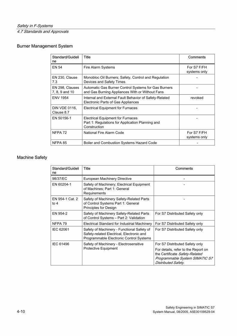
Safety in F-Systems 4.7 Standards and Approvals
Safety Engineering in SIMATIC S7 4-10 System Manual, 08/2005, A5E00109529-04
Burner Management System
Standard/Guideline
Title Comments
EN 54 Fire Alarm Systems For S7 F/FH systems only
EN 230, Clause 7.3
Monobloc Oil Burners; Safety, Control and Regulation Devices and Safety Times
-
EN 298, Clauses 7, 8, 9 and 10
Automatic Gas Burner Control Systems for Gas Burners and Gas Burning Appliances With or Without Fans
-
ENV 1954 Internal and External Fault Behavior of Safety-Related Electronic Parts of Gas Appliances
revoked
DIN VDE 0116, Clause 8.7
Electrical Equipment for Furnaces -
EN 50156-1 Electrical Equipment for Furnaces Part 1: Regulations for Application Planning and Construction
-
NFPA 72 National Fire Alarm Code For S7 F/FH systems only
NFPA 85 Boiler and Combustion Systems Hazard Code -
Machine Safety
Standard/Guideline
Title Comments
98/37/EC European Machinery Directive - EN 60204-1 Safety of Machinery; Electrical Equipment
of Machines; Part 1: General Requirements
-
EN 954-1 Cat. 2 to 4
Safety of Machinery Safety-Related Parts of Control Systems Part 1: General Principles for Design
-
EN 954-2 Safety of Machinery Safety-Related Parts of Control Systems – Part 2: Validation
For S7 Distributed Safety only
NFPA 79 Electrical Standard for Industrial Machinery For S7 Distributed Safety only IEC 62061 Safety of Machinery - Functional Safety of
Safety-related Electrical, Electronic and Programmable Electronic Control Systems
For S7 Distributed Safety only
IEC 61496 Safety of Machinery - Electrosensitive Protective Equipment
For S7 Distributed Safety only For details, refer to the Report on the Certificate Safety-Related Programmable System SIMATIC S7 Distributed Safety.
Safety in F-Systems 4.7 Standards and Approvals
Safety Engineering in SIMATIC S7 System Manual, 08/2005, A5E00109529-04 4-11
Presses
Standard/Guideline
Title Comments
EN 692 Mechanical Presses For S7 Distributed Safety only EN 693 Werkzeugmaschinen Pressen
(Machine tools presses) For S7 Distributed Safety only
EN 12622 Werkzeugmaschinen von Werkzeugmaschinen Gesenkbiegepressen(Machine tools of Machine tools press brakes)
For S7 Distributed Safety only
Standards and Guidelines Regarding Miscellaneous Properties
Standard/Guideline
Title Comments
IEC 61131-2 Programmable Controllers - Equipment Requirements and Tests 89/336/EEC
-
EN 50178 Electronic Equipment for Use in Power Installations - EN 60068 Environmental Testing - EN 55011 Limits and Methods of Measurement of Radio
Disturbance Characteristics of Industrial, Scientific and Medical (ISM) Radio-Frequency Equipment
revoked
EN 50081-2 Electromagnetic Compatibility; Generic Emission Standard; Part 2: Industrial Environment
revoked
EN 50082-2 Electromagnetic Compatibility - Generic Immunity Standard; Part 2: Industrial Environment
For S7 F/FH systems only
EN 61000-6-2 EN 61000-6-4
EMC Generic Standards – Immunity for Industrial Environments
-
73/23/EEC European Low Voltage Directive - 93/68/EEC European EMC Directive - UL 508 Industrial Control Equipment -
Note The environmental-related requirements for F-CPUs and the F-I/O must be adhered to (see technical specifications in the applicable manuals).
Safety in F-Systems 4.8 Safety Requirements
Safety Engineering in SIMATIC S7 4-12 System Manual, 08/2005, A5E00109529-04
4.8 4.8 Safety Requirements
Standardized Safety Requirements The following safety requirements can be met with S7 Distributed Safety and S7 F/FH Systems F-systems:
• Safety class (Safety Integrity Level) SIL1 to SIL3 in accordance with IEC 61508
• Category 2 to Category 4 in accordance with EN 954-1
Determining the Safety Integrity Level in Accordance with IEC 61508-5 The qualitative methods of the risk graphs enable the safety integrity level for a safety-related system to be determined based on knowledge of the risk factors involved:
Figure 4-1 Risk Graphs in Accordance with IEC 61508-5
S Starting point of the analysis for risk reduction C Risk parameter for the effect F Risk parameter for the frequency and exposure time P Risk parameter for possibility of avoiding dangerous occurrence W Probability of occurrence of undesirable event --- No safety requirements a No special safety requirements b A single electrical/electronic/programmable electronic
system is not sufficient. 1, 2, 3, 4 Safety integrity level
Safety in F-Systems 4.8 Safety Requirements
Safety Engineering in SIMATIC S7 System Manual, 08/2005, A5E00109529-04 4-13
Risk Parameters Risk parameters have the following meaning in accordance with DIN V 61508-5:
Table 4-1 Meaning of the risk parameters in accordance with IEC 61508-5
Parameter Meaning Effect (C ) CA Minor injury CB Major irreversible injury to one or more persons; fatality of a person CC Multiple fatalities CD Large number of fatalities Frequency and exposure time in hazardous area (F) FA Exposed to hazardous area seldom to often FB Exposed to hazardous area more often to continuous Possibility of avoiding dangerous occurrence (P) PA Possible under certain circumstances PB Almost impossible Probability of the undesirable event (W) W1 Very low W2 Low W3 Relatively high
Safety Integrity Level in Accordance with IEC 61508 For each "Safety Integrity Level“ (SIL), IEC 61508 defines the target measure to be the probability of failure of a safety function assigned to a fail-safe system.
Table 4-2 Safety Integrity Level in Accordance with IEC 61508
Safety Integrity Level
Operation in Low Demand Mode Low demand mode (average probability of failure on demand)
Operation in High Demand or Continuous Mode High demand/continuous mode (probability of a dangerous failure per hour)
4 ≥ 10-5 to < 10-4 ≥ 10-9 to < 10-8 3 ≥ 10-4 to < 10-3 ≥ 10-8 to < 10-7 2 ≥ 10-3 to < 10-2 ≥ 10-7 to < 10-6 1 ≥ 10-2 to < 10-1 ≥ 10-6 to < 10-5
Safety in F-Systems 4.8 Safety Requirements
Safety Engineering in SIMATIC S7 4-14 System Manual, 08/2005, A5E00109529-04
Explanations for Table In general, actuators and sensors are the largest contributor to the failure probabilities in the above table.
In all cases, the safety function encompasses the entire chain from information acquisition to information processing to the intended action.
The devices involved, such as an S7 F/FH Systems F-system, sensors, and actuators, must collectively comply with the SIL or Category determined during the risk assessment.
If control functions and associated protection functions are implemented together in S7 Distributed Safety or S7 F/FH Systems, operation is in high demand mode or continuous mode.
Risk Analysis in Accordance with IEC 61508 As shown in the following figure, an F-system prevents potential dangers or reduces them to a tolerable level through appropriate organizational and technical measures.
Figure 4-2 Risk Analysis in Accordance with IEC 61508
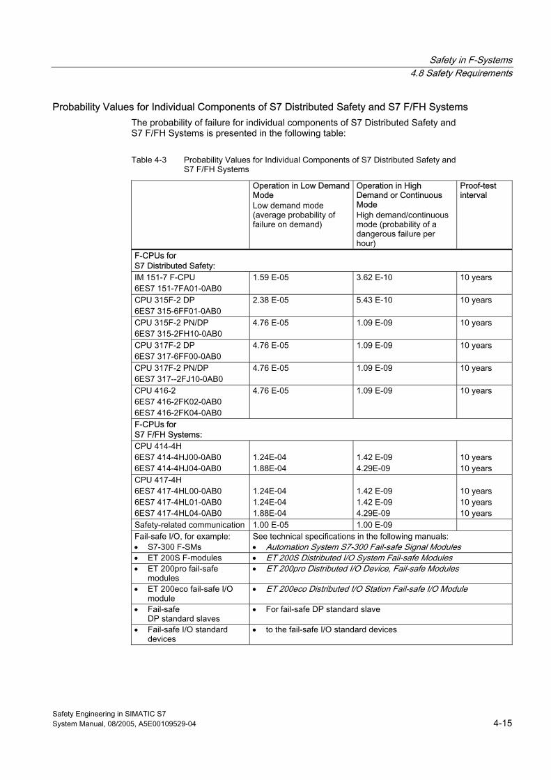
Safety in F-Systems 4.8 Safety Requirements
Safety Engineering in SIMATIC S7 System Manual, 08/2005, A5E00109529-04 4-15
Probability Values for Individual Components of S7 Distributed Safety and S7 F/FH Systems The probability of failure for individual components of S7 Distributed Safety and S7 F/FH Systems is presented in the following table:
Table 4-3 Probability Values for Individual Components of S7 Distributed Safety and S7 F/FH Systems
Operation in Low Demand Mode Low demand mode (average probability of failure on demand)
Operation in High Demand or Continuous Mode High demand/continuous mode (probability of a dangerous failure per hour)
Proof-test interval
F-CPUs for S7 Distributed Safety: IM 151-7 F-CPU 6ES7 151-7FA01-0AB0
1.59 E-05 3.62 E-10 10 years
CPU 315F-2 DP 6ES7 315-6FF01-0AB0
2.38 E-05 5.43 E-10 10 years
CPU 315F-2 PN/DP 6ES7 315-2FH10-0AB0
4.76 E-05 1.09 E-09 10 years
CPU 317F-2 DP 6ES7 317-6FF00-0AB0
4.76 E-05 1.09 E-09 10 years
CPU 317F-2 PN/DP 6ES7 317--2FJ10-0AB0
4.76 E-05 1.09 E-09 10 years
CPU 416-2 6ES7 416-2FK02-0AB0 6ES7 416-2FK04-0AB0
4.76 E-05 1.09 E-09 10 years
F-CPUs for S7 F/FH Systems: CPU 414-4H 6ES7 414-4HJ00-0AB0 6ES7 414-4HJ04-0AB0
1.24E-04 1.88E-04
1.42 E-09 4.29E-09
10 years 10 years
CPU 417-4H 6ES7 417-4HL00-0AB0 6ES7 417-4HL01-0AB0 6ES7 417-4HL04-0AB0
1.24E-04 1.24E-04 1.88E-04
1.42 E-09 1.42 E-09 4.29E-09
10 years 10 years 10 years
Safety-related communication 1.00 E-05 1.00 E-09 Fail-safe I/O, for example: • S7-300 F-SMs
See technical specifications in the following manuals: • Automation System S7-300 Fail-safe Signal Modules
• ET 200S F-modules • ET 200S Distributed I/O System Fail-safe Modules • ET 200pro fail-safe
modules • ET 200pro Distributed I/O Device, Fail-safe Modules
• ET 200eco fail-safe I/O module
• ET 200eco Distributed I/O Station Fail-safe I/O Module
• Fail-safe DP standard slaves
• For fail-safe DP standard slave
• Fail-safe I/O standard devices
• to the fail-safe I/O standard devices
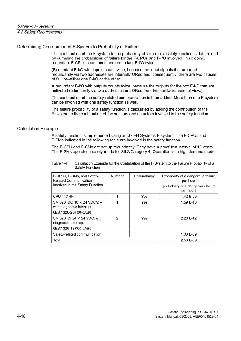
Safety in F-Systems 4.8 Safety Requirements
Safety Engineering in SIMATIC S7 4-16 System Manual, 08/2005, A5E00109529-04
Determining Contribution of F-System to Probability of Failure The contribution of the F-system to the probability of failure of a safety function is determined by summing the probabilities of failure for the F-CPUs and F-I/O involved. In so doing, redundant F-CPUs count once and redundant F-I/O twice.
(Redundant F-I/O with inputs count twice, because the input signals that are read redundantly via two addresses are internally ORed and, consequently, there are two causes of failure--either one F-I/O or the other.
A redundant F-I/O with outputs counts twice, because the outputs for the two F-I/O that are activated redundantly via two addresses are ORed from the hardware point of view.)
The contribution of the safety-related communication is then added. More than one F-system can be involved with one safety function as well.
The failure probability of a safety function is calculated by adding the contribution of the F-system to the contribution of the sensors and actuators involved in the safety function.
Calculation Example A safety function is implemented using an S7 FH Systems F-system. The F-CPUs and F-SMs indicated in the following table are involved in the safety function.
The F-CPU and F-SMs are set up redundantly. They have a proof-test interval of 10 years. The F-SMs operate in safety mode for SIL3/Category 4. Operation is in high demand mode:
Table 4-4 Calculation Example for the Contribution of the F-System to the Failure Probability of a Safety Function
F-CPUs, F-SMs, and Safety-Related Communication Involved in the Safety Function
Number Redundancy Probability of a dangerous failure per hour
(probability of a dangerous failure per hour)
CPU 417-4H 1 Yes 1.42 E-09 SM 326; DO 10 ☓ 24 VDC/2 A with diagnostic interrupt 6ES7 326-2BF00-0AB0
1 Yes 1.59 E-10
SM 326; DI 24 ☓ 24 VDC, with diagnostic interrupt 6ES7 326-1BK00-0AB0
2 Yes 2.28 E-12
Safety-related communication 1.00 E-09 Total 2.58 E-09
Safety Engineering in SIMATIC S7 System Manual, 08/2005, A5E00109529-04 5-1
Achievable Safety Classes with F-I/O 55.1 5.1 Introduction
Overview This chapter presents the options available for achieving safety classes SIL2/Category 3 and SIL3/Category 4 with fail-safe I/O in S7 Distributed Safety and S7 F/FH Systems. The information relates to the F-I/O of the SIMATIC S7 product family, that is, S7-300 F-SMs, F-modules ET 200S and ET 200pro, and the ET 200eco fail-safe I/O module.
Additional Information The F-I/O used determines whether the options described can be implemented in your application. For information on this, refer to the following manuals for the specific F-I/O:
• For S7-300 F-SMs: Automation System S7-300 Fail-safe Signal Modules manual
• For ET 200S fail-safe modules: ET 200S Distributed I/O System Fail-safe Modules manual
• For ET 200pro fail-safe modules: ET 200pro Distributed I/O Device Fail-safe Modules manual
• For the ET 200eco fail-safe module: ET 200eco Distributed I/O Station Fail-safe I/O Module manual
Achieving the Safety Class for F-I/O with Inputs The required safety class is achieved for F-I/O with inputs as follows:
• Internally, using test circuits and automatic tests
• Externally, by the type of sensor evaluation, that is, the wiring of the sensor determines safety class SIL2/Category 3 or SIL3/Category 4
Achieving the Safety Class for F-I/O with Outputs The required safety class is achieved for F-I/O with outputs as follows:
• Internally, using test circuits and automatic tests
• Externally, by the prescribed interconnection of the actuator In addition, it may be necessary to have test signals from the process read by the F-I/O and evaluated by the safety program.
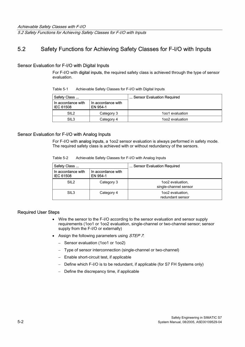
Achievable Safety Classes with F-I/O 5.2 Safety Functions for Achieving Safety Classes for F-I/O with Inputs
Safety Engineering in SIMATIC S7 5-2 System Manual, 08/2005, A5E00109529-04
5.2 5.2 Safety Functions for Achieving Safety Classes for F-I/O with Inputs
Sensor Evaluation for F-I/O with Digital Inputs For F-I/O with digital inputs, the required safety class is achieved through the type of sensor evaluation.
Table 5-1 Achievable Safety Classes for F-I/O with Digital Inputs
Safety Class ... In accordance with IEC 61508
In accordance with EN 954-1
... Sensor Evaluation Required
SIL2 Category 3 1oo1 evaluation SIL3 Category 4 1oo2 evaluation
Sensor Evaluation for F-I/O with Analog Inputs For F-I/O with analog inputs, a 1oo2 sensor evaluation is always performed in safety mode. The required safety class is achieved with or without redundancy of the sensors.
Table 5-2 Achievable Safety Classes for F-I/O with Analog Inputs
Safety Class ... In accordance with IEC 61508
In accordance with EN 954-1
... Sensor Evaluation Required
SIL2 Category 3 1oo2 evaluation, single-channel sensor
SIL3 Category 4 1oo2 evaluation, redundant sensor
Required User Steps • Wire the sensor to the F-I/O according to the sensor evaluation and sensor supply
requirements (1oo1 or 1oo2 evaluation, single-channel or two-channel sensor; sensor supply from the F-I/O or externally)
• Assign the following parameters using STEP 7:
– Sensor evaluation (1oo1 or 1oo2)
– Type of sensor interconnection (single-channel or two-channel)
– Enable short-circuit test, if applicable
– Define which F-I/O is to be redundant, if applicable (for S7 FH Systems only)
– Define the discrepancy time, if applicable
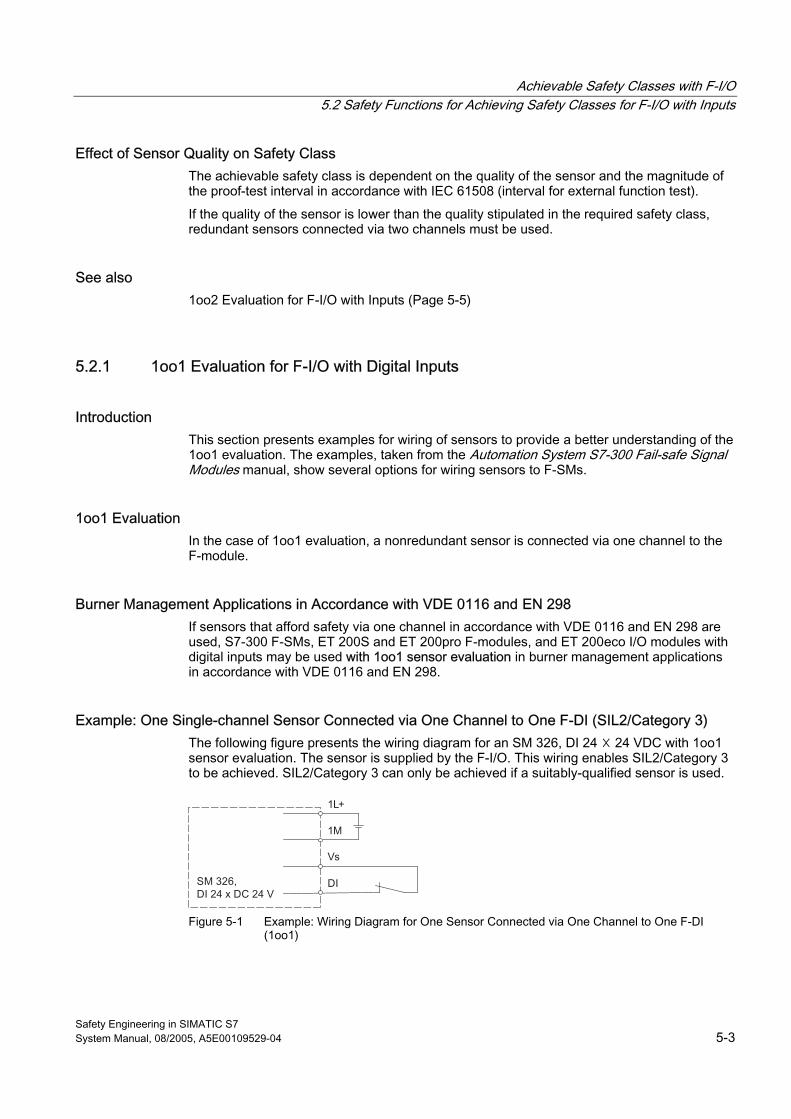
Achievable Safety Classes with F-I/O 5.2 Safety Functions for Achieving Safety Classes for F-I/O with Inputs
Safety Engineering in SIMATIC S7 System Manual, 08/2005, A5E00109529-04 5-3
Effect of Sensor Quality on Safety Class The achievable safety class is dependent on the quality of the sensor and the magnitude of the proof-test interval in accordance with IEC 61508 (interval for external function test).
If the quality of the sensor is lower than the quality stipulated in the required safety class, redundant sensors connected via two channels must be used.
See also 1oo2 Evaluation for F-I/O with Inputs (Page 5-5)
5.2.1 1oo1 Evaluation for F-I/O with Digital Inputs
Introduction This section presents examples for wiring of sensors to provide a better understanding of the 1oo1 evaluation. The examples, taken from the Automation System S7-300 Fail-safe Signal Modules manual, show several options for wiring sensors to F-SMs.
1oo1 Evaluation In the case of 1oo1 evaluation, a nonredundant sensor is connected via one channel to the F-module.
Burner Management Applications in Accordance with VDE 0116 and EN 298 If sensors that afford safety via one channel in accordance with VDE 0116 and EN 298 are used, S7-300 F-SMs, ET 200S and ET 200pro F-modules, and ET 200eco I/O modules with digital inputs may be used with 1oo1 sensor evaluation in burner management applications in accordance with VDE 0116 and EN 298.
Example: One Single-channel Sensor Connected via One Channel to One F-DI (SIL2/Category 3) The following figure presents the wiring diagram for an SM 326, DI 24 ☓ 24 VDC with 1oo1 sensor evaluation. The sensor is supplied by the F-I/O. This wiring enables SIL2/Category 3 to be achieved. SIL2/Category 3 can only be achieved if a suitably-qualified sensor is used.
Figure 5-1 Example: Wiring Diagram for One Sensor Connected via One Channel to One F-DI
(1oo1)
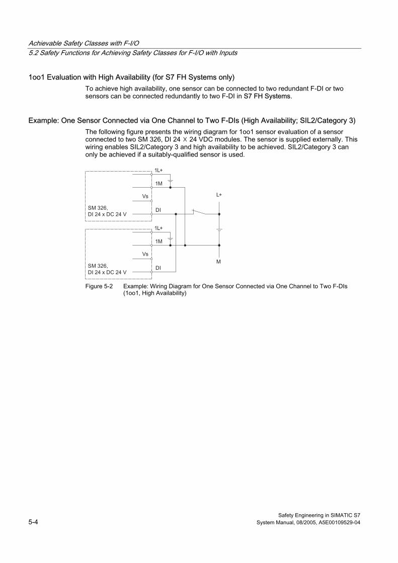
Achievable Safety Classes with F-I/O 5.2 Safety Functions for Achieving Safety Classes for F-I/O with Inputs
Safety Engineering in SIMATIC S7 5-4 System Manual, 08/2005, A5E00109529-04
1oo1 Evaluation with High Availability (for S7 FH Systems only) To achieve high availability, one sensor can be connected to two redundant F-DI or two sensors can be connected redundantly to two F-DI in S7 FH Systems.
Example: One Sensor Connected via One Channel to Two F-DIs (High Availability; SIL2/Category 3) The following figure presents the wiring diagram for 1oo1 sensor evaluation of a sensor connected to two SM 326, DI 24 ☓ 24 VDC modules. The sensor is supplied externally. This wiring enables SIL2/Category 3 and high availability to be achieved. SIL2/Category 3 can only be achieved if a suitably-qualified sensor is used.
Figure 5-2 Example: Wiring Diagram for One Sensor Connected via One Channel to Two F-DIs
(1oo1, High Availability)
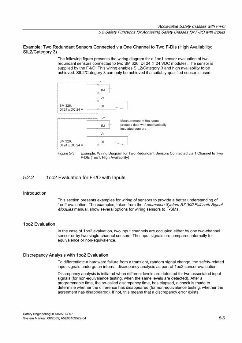
Achievable Safety Classes with F-I/O 5.2 Safety Functions for Achieving Safety Classes for F-I/O with Inputs
Safety Engineering in SIMATIC S7 System Manual, 08/2005, A5E00109529-04 5-5
Example: Two Redundant Sensors Connected via One Channel to Two F-DIs (High Availability; SIL2/Category 3)
The following figure presents the wiring diagram for a 1oo1 sensor evaluation of two redundant sensors connected to two SM 326, DI 24 ☓ 24 VDC modules. The sensor is supplied by the F-I/O. This wiring enables SIL2/Category 3 and high availability to be achieved. SIL2/Category 3 can only be achieved if a suitably-qualified sensor is used.
Figure 5-3 Example: Wiring Diagram for Two Redundant Sensors Connected via 1 Channel to Two
F-DIs (1oo1, High Availability)
5.2.2 1oo2 Evaluation for F-I/O with Inputs
Introduction This section presents examples for wiring of sensors to provide a better understanding of 1oo2 evaluation. The examples, taken from the Automation System S7-300 Fail-safe Signal Modules manual, show several options for wiring sensors to F-SMs.
1oo2 Evaluation In the case of 1oo2 evaluation, two input channels are occupied either by one two-channel sensor or by two single-channel sensors. The input signals are compared internally for equivalence or non-equivalence.
Discrepancy Analysis with 1oo2 Evaluation To differentiate a hardware failure from a transient, random signal change, the safety-related input signals undergo an internal discrepancy analysis as part of 1oo2 sensor evaluation.
Discrepancy analysis is initiated when different levels are detected for two associated input signals (for non-equivalence testing, when the same levels are detected). After a programmable time, the so-called discrepancy time, has elapsed, a check is made to determine whether the difference has disappeared (for non-equivalence testing: whether the agreement has disappeared). If not, this means that a discrepancy error exists.
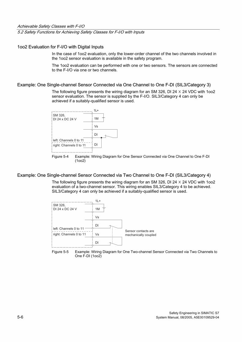
Achievable Safety Classes with F-I/O 5.2 Safety Functions for Achieving Safety Classes for F-I/O with Inputs
Safety Engineering in SIMATIC S7 5-6 System Manual, 08/2005, A5E00109529-04
1oo2 Evaluation for F-I/O with Digital Inputs In the case of 1oo2 evaluation, only the lower-order channel of the two channels involved in the 1oo2 sensor evaluation is available in the safety program.
The 1oo2 evaluation can be performed with one or two sensors. The sensors are connected to the F-I/O via one or two channels.
Example: One Single-channel Sensor Connected via One Channel to One F-DI (SIL3/Category 3) The following figure presents the wiring diagram for an SM 326, DI 24 ☓ 24 VDC with 1oo2 sensor evaluation. The sensor is supplied by the F-I/O. SIL3/Category 4 can only be achieved if a suitably-qualified sensor is used.
Figure 5-4 Example: Wiring Diagram for One Sensor Connected via One Channel to One F-DI
(1oo2)
Example: One Single-channel Sensor Connected via Two Channel to One F-DI (SIL3/Category 4) The following figure presents the wiring diagram for an SM 326, DI 24 ☓ 24 VDC with 1oo2 evaluation of a two-channel sensor. This wiring enables SIL3/Category 4 to be achieved. SIL3/Category 4 can only be achieved if a suitably-qualified sensor is used.
Figure 5-5 Example: Wiring Diagram for One Two-channel Sensor Connected via Two Channels to
One F-DI (1oo2)
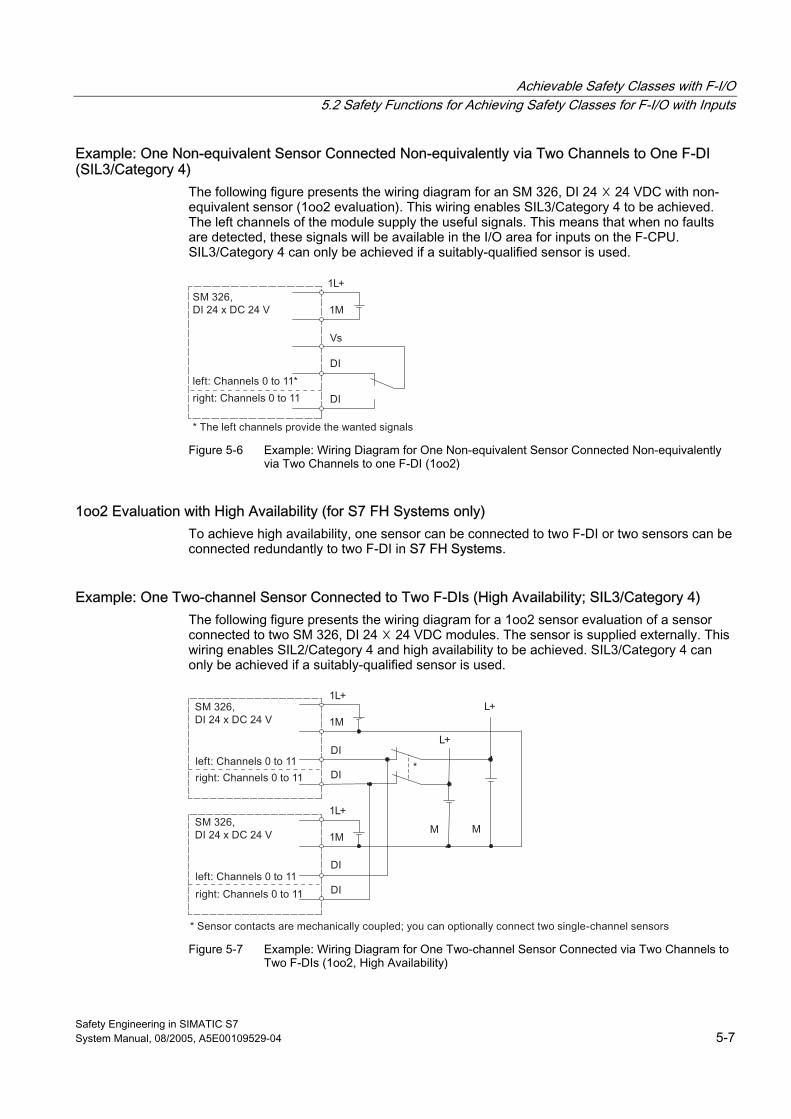
Achievable Safety Classes with F-I/O 5.2 Safety Functions for Achieving Safety Classes for F-I/O with Inputs
Safety Engineering in SIMATIC S7 System Manual, 08/2005, A5E00109529-04 5-7
Example: One Non-equivalent Sensor Connected Non-equivalently via Two Channels to One F-DI (SIL3/Category 4)
The following figure presents the wiring diagram for an SM 326, DI 24 ☓ 24 VDC with non-equivalent sensor (1oo2 evaluation). This wiring enables SIL3/Category 4 to be achieved. The left channels of the module supply the useful signals. This means that when no faults are detected, these signals will be available in the I/O area for inputs on the F-CPU. SIL3/Category 4 can only be achieved if a suitably-qualified sensor is used.
Figure 5-6 Example: Wiring Diagram for One Non-equivalent Sensor Connected Non-equivalently
via Two Channels to one F-DI (1oo2)
1oo2 Evaluation with High Availability (for S7 FH Systems only) To achieve high availability, one sensor can be connected to two F-DI or two sensors can be connected redundantly to two F-DI in S7 FH Systems.
Example: One Two-channel Sensor Connected to Two F-DIs (High Availability; SIL3/Category 4) The following figure presents the wiring diagram for a 1oo2 sensor evaluation of a sensor connected to two SM 326, DI 24 ☓ 24 VDC modules. The sensor is supplied externally. This wiring enables SIL2/Category 4 and high availability to be achieved. SIL3/Category 4 can only be achieved if a suitably-qualified sensor is used.
Figure 5-7 Example: Wiring Diagram for One Two-channel Sensor Connected via Two Channels to
Two F-DIs (1oo2, High Availability)
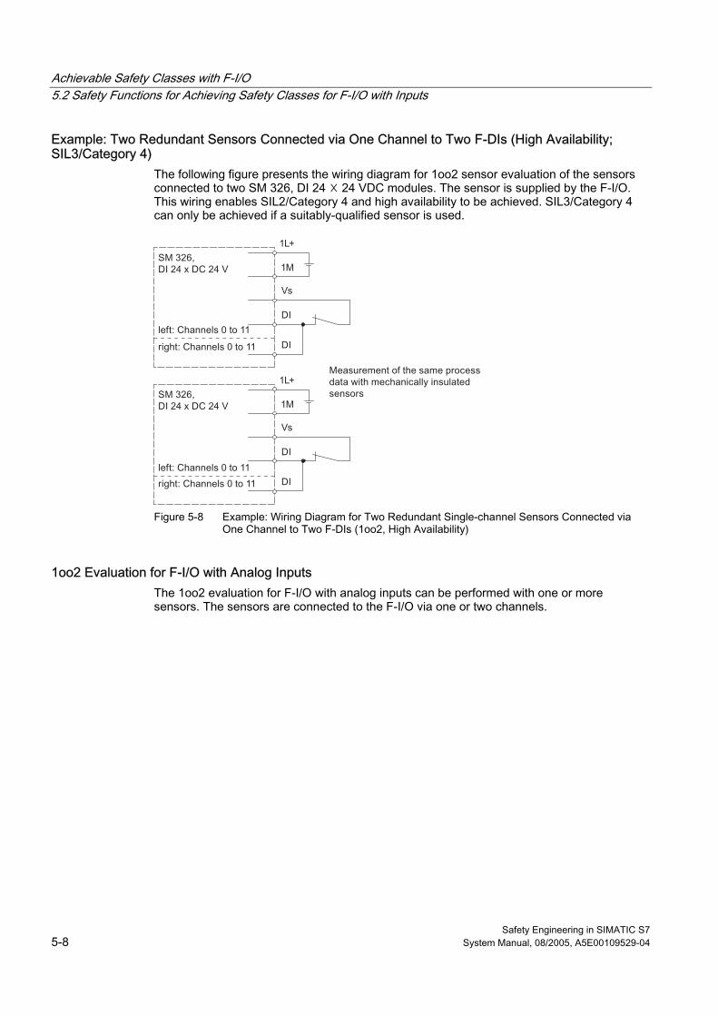
Achievable Safety Classes with F-I/O 5.2 Safety Functions for Achieving Safety Classes for F-I/O with Inputs
Safety Engineering in SIMATIC S7 5-8 System Manual, 08/2005, A5E00109529-04
Example: Two Redundant Sensors Connected via One Channel to Two F-DIs (High Availability; SIL3/Category 4)
The following figure presents the wiring diagram for 1oo2 sensor evaluation of the sensors connected to two SM 326, DI 24 ☓ 24 VDC modules. The sensor is supplied by the F-I/O. This wiring enables SIL2/Category 4 and high availability to be achieved. SIL3/Category 4 can only be achieved if a suitably-qualified sensor is used.
Figure 5-8 Example: Wiring Diagram for Two Redundant Single-channel Sensors Connected via
One Channel to Two F-DIs (1oo2, High Availability)
1oo2 Evaluation for F-I/O with Analog Inputs The 1oo2 evaluation for F-I/O with analog inputs can be performed with one or more sensors. The sensors are connected to the F-I/O via one or two channels.
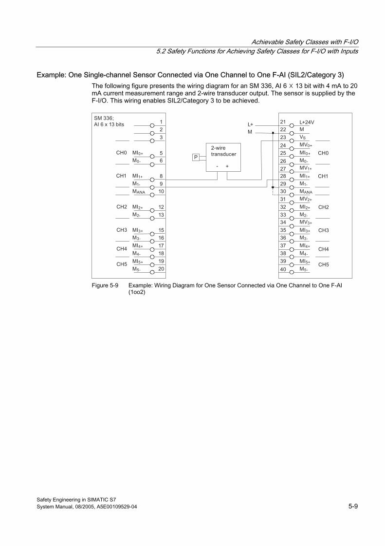
Achievable Safety Classes with F-I/O 5.2 Safety Functions for Achieving Safety Classes for F-I/O with Inputs
Safety Engineering in SIMATIC S7 System Manual, 08/2005, A5E00109529-04 5-9
Example: One Single-channel Sensor Connected via One Channel to One F-AI (SIL2/Category 3) The following figure presents the wiring diagram for an SM 336, AI 6 ☓ 13 bit with 4 mA to 20 mA current measurement range and 2-wire transducer output. The sensor is supplied by the F-I/O. This wiring enables SIL2/Category 3 to be achieved.
Figure 5-9 Example: Wiring Diagram for One Sensor Connected via One Channel to One F-AI
(1oo2)
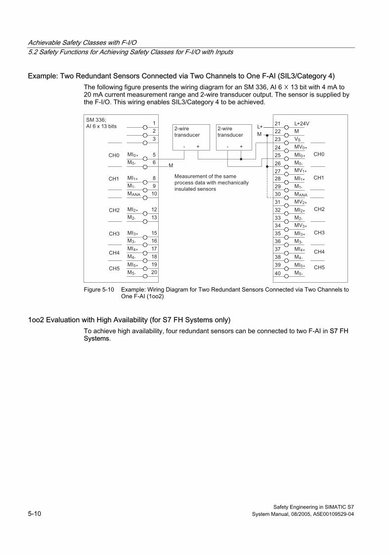
Achievable Safety Classes with F-I/O 5.2 Safety Functions for Achieving Safety Classes for F-I/O with Inputs
Safety Engineering in SIMATIC S7 5-10 System Manual, 08/2005, A5E00109529-04
Example: Two Redundant Sensors Connected via Two Channels to One F-AI (SIL3/Category 4) The following figure presents the wiring diagram for an SM 336, AI 6 ☓ 13 bit with 4 mA to 20 mA current measurement range and 2-wire transducer output. The sensor is supplied by the F-I/O. This wiring enables SIL3/Category 4 to be achieved.
Figure 5-10 Example: Wiring Diagram for Two Redundant Sensors Connected via Two Channels to
One F-AI (1oo2)
1oo2 Evaluation with High Availability (for S7 FH Systems only) To achieve high availability, four redundant sensors can be connected to two F-AI in S7 FH Systems.
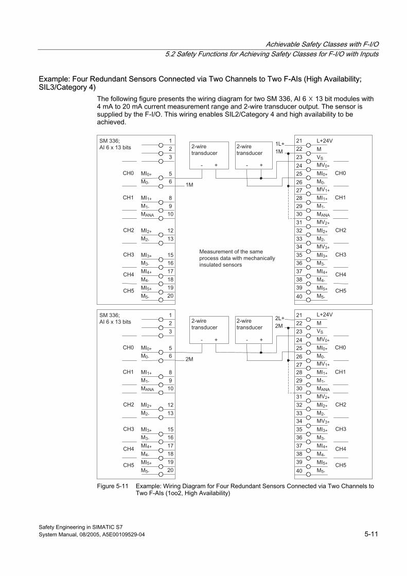
Achievable Safety Classes with F-I/O 5.2 Safety Functions for Achieving Safety Classes for F-I/O with Inputs
Safety Engineering in SIMATIC S7 System Manual, 08/2005, A5E00109529-04 5-11
Example: Four Redundant Sensors Connected via Two Channels to Two F-AIs (High Availability; SIL3/Category 4)
The following figure presents the wiring diagram for two SM 336, AI 6 ☓ 13 bit modules with 4 mA to 20 mA current measurement range and 2-wire transducer output. The sensor is supplied by the F-I/O. This wiring enables SIL2/Category 4 and high availability to be achieved.
Figure 5-11 Example: Wiring Diagram for Four Redundant Sensors Connected via Two Channels to
Two F-AIs (1oo2, High Availability)
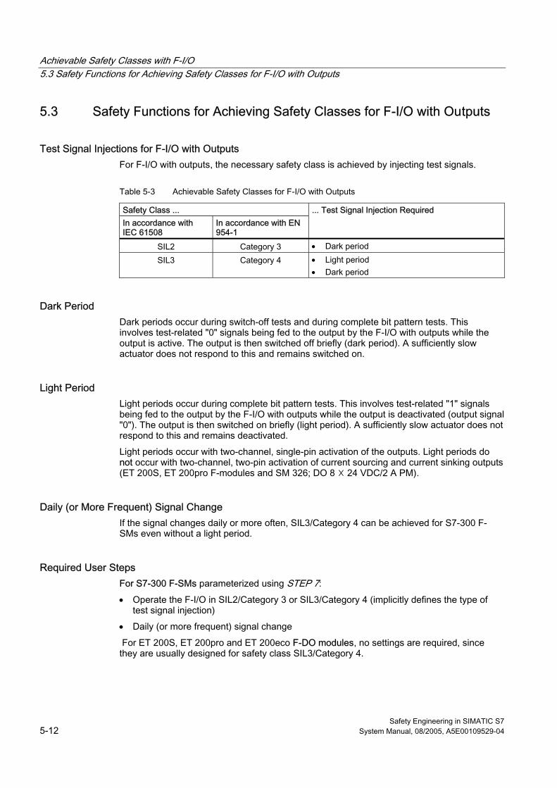
Achievable Safety Classes with F-I/O 5.3 Safety Functions for Achieving Safety Classes for F-I/O with Outputs
Safety Engineering in SIMATIC S7 5-12 System Manual, 08/2005, A5E00109529-04
5.3 5.3 Safety Functions for Achieving Safety Classes for F-I/O with Outputs
Test Signal Injections for F-I/O with Outputs For F-I/O with outputs, the necessary safety class is achieved by injecting test signals.
Table 5-3 Achievable Safety Classes for F-I/O with Outputs
Safety Class ... In accordance with IEC 61508
In accordance with EN 954-1
... Test Signal Injection Required
SIL2 Category 3 • Dark period SIL3 Category 4 • Light period
• Dark period
Dark Period Dark periods occur during switch-off tests and during complete bit pattern tests. This involves test-related "0" signals being fed to the output by the F-I/O with outputs while the output is active. The output is then switched off briefly (dark period). A sufficiently slow actuator does not respond to this and remains switched on.
Light Period Light periods occur during complete bit pattern tests. This involves test-related "1" signals being fed to the output by the F-I/O with outputs while the output is deactivated (output signal "0"). The output is then switched on briefly (light period). A sufficiently slow actuator does not respond to this and remains deactivated.
Light periods occur with two-channel, single-pin activation of the outputs. Light periods do not occur with two-channel, two-pin activation of current sourcing and current sinking outputs (ET 200S, ET 200pro F-modules and SM 326; DO 8 ☓ 24 VDC/2 A PM).
Daily (or More Frequent) Signal Change If the signal changes daily or more often, SIL3/Category 4 can be achieved for S7-300 F-SMs even without a light period.
Required User Steps For S7-300 F-SMs parameterized using STEP 7:
• Operate the F-I/O in SIL2/Category 3 or SIL3/Category 4 (implicitly defines the type of test signal injection)
• Daily (or more frequent) signal change
For ET 200S, ET 200pro and ET 200eco F-DO modules, no settings are required, since they are usually designed for safety class SIL3/Category 4.
Safety Engineering in SIMATIC S7 System Manual, 08/2005, A5E00109529-04 6-1
Configuring F-Systems 66.1 6.1 Introduction
F-I/O Configured Same as in Standard System S7 Distributed Safety and S7 F/FH Systems fail-safe systems are configured in basically the same way as standard S7-300 and S7-400 stations. The only difference is that the object properties for the fail-safe components (F-CPU and F-I/O) include some special tabs.
F-Components Requiring Configuration by User The following hardware components must be configured:
• F-CPU, such as CPU 315F-2 DP
• F-I/O, such as:
– ET 200S fail-safe modules
– ET 200pro fail-safe modules
– ET 200eco fail-safe I/O module
– Fail-safe S7-300 signal modules (for centralized configuration near the F-CPU or decentralized configuration in ET 200M)
– Fail-safe DP standard slaves/standard I/O devices
Overview This chapter provides an overview for configuring the components of an F-system. Minor differences between S7 Distributed Safety and S7 F/FH Systems are individually noted.
Additional Information You can find detailed information about configuring the hardware in the STEP 7 online help. For specific rules and detailed example projects for configuring and programming F-systems, refer to:
• For S7 Distributed Safety: Getting Started S7 Distributed Safety manual
• For S7 Distributed Safety: S7 Distributed Safety Configuring and Programming manual
• For S7 F/FH Systems: Programmable Controllers S7 F/FH manual
• For S7 F/FH Systems: step7\Examples directory
Configuring F-Systems 6.2 Configuring the F-CPU
Safety Engineering in SIMATIC S7 6-2 System Manual, 08/2005, A5E00109529-04
6.2 6.2 Configuring the F-CPU
Configuration The F-CPU is listed in the hardware catalog of HW Config along with the other S7-300 and S7-400 CPUs.
The F-CPU is configured according to the same scheme used for standard CPUs. Once the F-CPU has been placed in the configuration table, you can access the configuration dialog by selecting the Edit > Object Properties menu command or by double-clicking the F-CPU.
In the "Protection" tab, you must configure the protection level for the F-CPU.
The S7 Distributed Safety CPU also has a specific tab for F-properties called "F Parameters"; this tab is not included for S7 F/FH systems.
Example of Configuring an F-CPU for S7 Distributed Safety The "F Parameters" tab for a CPU 315F-2 DP is shown below.
S7 Distributed Safety automatically assigns the PROFIsafe addresses. The "Base for PROFIsafe addresses" information is required for internal management of the PROFIsafe addresses of the F-system. PROFIsafe addresses are used to uniquely identify the source and destination.
In addition, the user reserves CPU resources (F-data areas, F function blocks, and F local data) for the safety program. These resources cannot be used in the safety program or the standard user program (reserved for automatically added F-blocks).
The parameters are explained in the context-sensitive online help for the tab and in the S7 Distributed Safety Configuring and Programming manual.
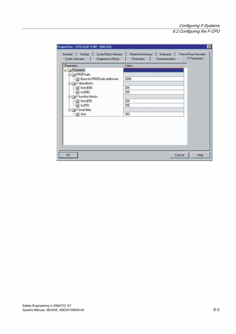
Configuring F-Systems 6.2 Configuring the F-CPU
Safety Engineering in SIMATIC S7 System Manual, 08/2005, A5E00109529-04 6-3
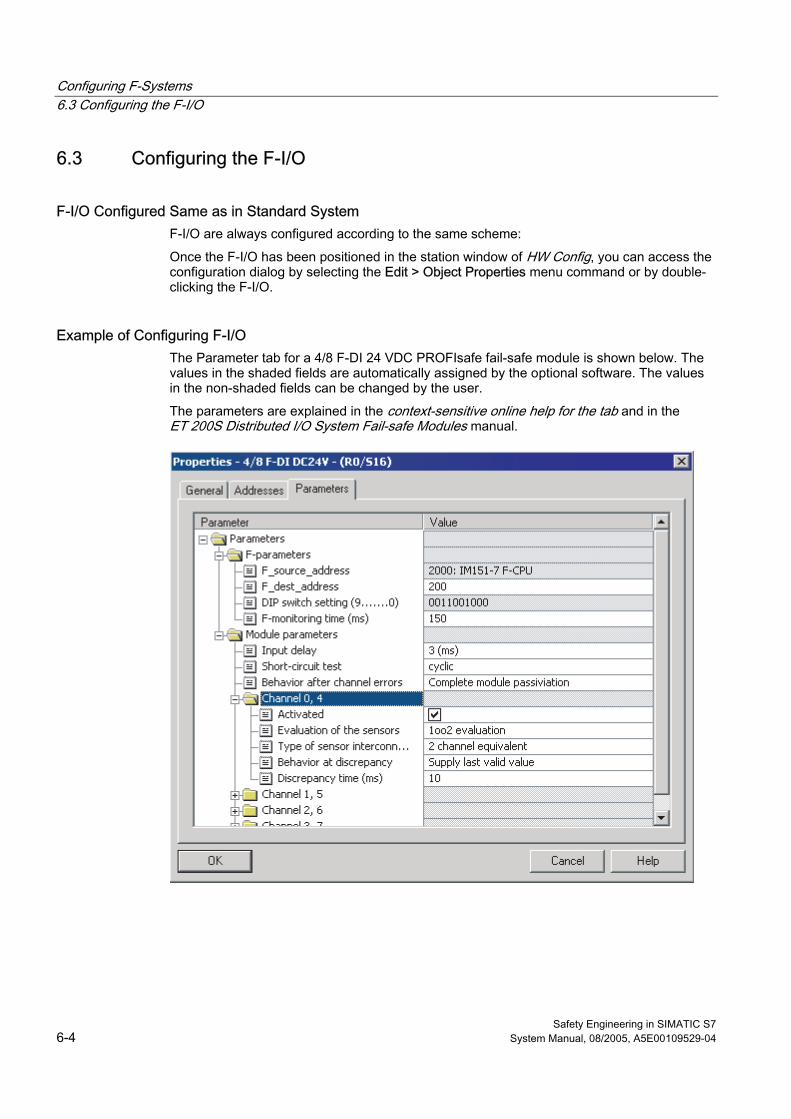
Configuring F-Systems 6.3 Configuring the F-I/O
Safety Engineering in SIMATIC S7 6-4 System Manual, 08/2005, A5E00109529-04
6.3 6.3 Configuring the F-I/O
F-I/O Configured Same as in Standard System F-I/O are always configured according to the same scheme:
Once the F-I/O has been positioned in the station window of HW Config, you can access the configuration dialog by selecting the Edit > Object Properties menu command or by double-clicking the F-I/O.
Example of Configuring F-I/O The Parameter tab for a 4/8 F-DI 24 VDC PROFIsafe fail-safe module is shown below. The values in the shaded fields are automatically assigned by the optional software. The values in the non-shaded fields can be changed by the user.
The parameters are explained in the context-sensitive online help for the tab and in the ET 200S Distributed I/O System Fail-safe Modules manual.
Configuring F-Systems 6.4 Configuring Fail-safe DP Standard Slaves and Fail-safe I/O Standard Devices
Safety Engineering in SIMATIC S7 System Manual, 08/2005, A5E00109529-04 6-5
6.4 6.4 Configuring Fail-safe DP Standard Slaves and Fail-safe I/O Standard Devices
Requirements In order to use fail-safe DP standard slaves with S7 Distributed Safety, the standard slaves must be on the PROFIBUS-DP and support the PROFIsafe bus profile. Fail-safe DP standard slaves that are used in a mixed configurations on PROFIBUS DP and PROFINET IO after IE/PB links, must support the PROFIsafe bus profile in the V2 mode.
In order to use fail-safe standard I/O devices with S7 Distributed Safety, the standard devices must be on the PROFINET IO and support the PROFIsafe bus profile in V2 mode.
Configuration with GSD/GSDML Files As is the case in a standard system, the basis for configuring fail-safe DP standard slaves/standard I/O devices is the specification of the device in the GSD/GSDML file (Generic Station Description/Generic Station Description Markup Language).
All the properties of a DP standard slave are saved in a GSD file. Standard I/O device properties are saved in the GSDML file. For fail-safe DP standard slaves/standard I/O devices, portions of the specification are ensured by a CRC.
GSD and GSDML files are supplied by the device manufacturers. The user imports the GSD/GSDML files into his project (see STEP 7 online help). Once the fail-safe DP standard slave / IO standard devices imported, it can be selected from the hardware catalog of HW Config.
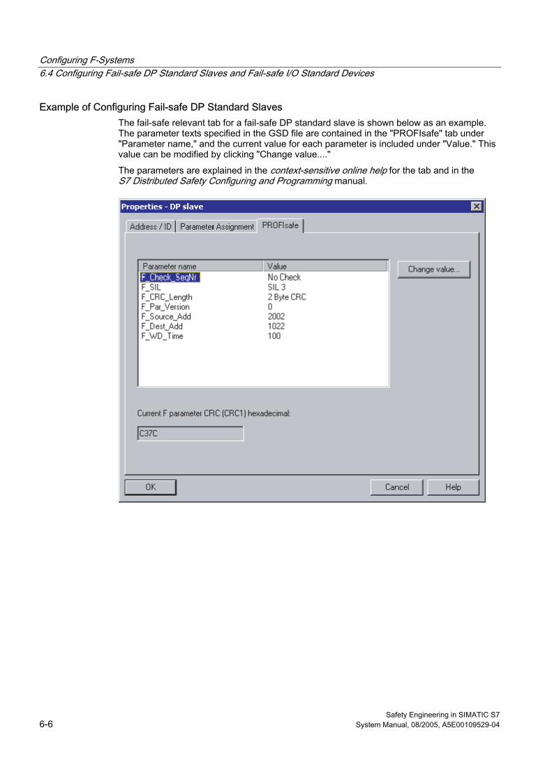
Configuring F-Systems 6.4 Configuring Fail-safe DP Standard Slaves and Fail-safe I/O Standard Devices
Safety Engineering in SIMATIC S7 6-6 System Manual, 08/2005, A5E00109529-04
Example of Configuring Fail-safe DP Standard Slaves The fail-safe relevant tab for a fail-safe DP standard slave is shown below as an example. The parameter texts specified in the GSD file are contained in the "PROFIsafe" tab under "Parameter name," and the current value for each parameter is included under "Value." This value can be modified by clicking "Change value...."
The parameters are explained in the context-sensitive online help for the tab and in the S7 Distributed Safety Configuring and Programming manual.
Safety Engineering in SIMATIC S7 System Manual, 08/2005, A5E00109529-04 7-1
Programming F-Systems 77.1 7.1 Introduction
Programming with Standard Programming Languages S7 Distributed Safety and S7 F/FH Systems fail-safe systems are programmed using standard programming languages of STEP 7.
Overview This chapter describes the program structure and the elements of the safety program.
The structure of the safety programs is described separately for S7 Distributed Safety and S7 F/FH Systems since there are fundamental differences in programming of the two systems.
Additional Information The procedure for programming the safety program is described in detail in the following manuals:
• For S7 Distributed Safety: S7 Distributed Safety Configuring and Programming manual
• For S7 F/FH Systems: Programmable Controllers S7 F/FH manual
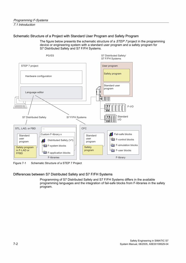
Programming F-Systems 7.1 Introduction
Safety Engineering in SIMATIC S7 7-2 System Manual, 08/2005, A5E00109529-04
Schematic Structure of a Project with Standard User Program and Safety Program The figure below presents the schematic structure of a STEP 7 project in the programming device or engineering system with a standard user program and a safety program for S7 Distributed Safety and S7 F/FH Systems.
Figure 7-1 Schematic Structure of a STEP 7 Project
Differences between S7 Distributed Safety and S7 F/FH Systems Programming of S7 Distributed Safety and S7 F/FH Systems differs in the available programming languages and the integration of fail-safe blocks from F-libraries in the safety program.
Programming F-Systems 7.2 Programming Languages for F-Systems
Safety Engineering in SIMATIC S7 System Manual, 08/2005, A5E00109529-04 7-3
7.2 7.2 Programming Languages for F-Systems
User Program in the F-CPU The user program in the F-CPU typically consists of a standard user program and a safety program. The standard user program is created in STEP 7 using standard programming languages such as STL, LAD, or FBD or the CFC programming language.
For S7 Distributed Safety, the safety program is programmed in F-FBD or F-LAD. For S7 F/FH systems, fail-safe blocks of an F-library are interconnected in CFC.
The safety program also includes fail-safe blocks for error detection and error response that are automatically amended by the add-on software. This ensures that failures and faults are detected and an appropriate response is triggered so that the F-system either stops in the safe state or goes to a safe state.
S7 Distributed Safety: F-FBD and F-LAD Programming Languages The F-FBD and F-LAD programming languages correspond in principle to the standard FBD/LAD languages. The standard FBD/LAD Editor in STEP 7 is used for programming.
The primary difference between the F-FBD and F-LAD programming languages and their standard counterparts lies in the limitations in the instruction set and data types and in the address areas that can be used.
S7 F/FH Systems: Programming Language CFC The safety program is created in individual Continuous Function Charts (CFC) from fail-safe blocks that are supplied in an F-library with the S7 F-Systems optional package.
F-Block Libraries The S7 Distributed Safety and S7 F Systems optional packages include the following for programming F-systems:
• For S7 Distributed Safety: Distributed Safety F-library (V1)
• For S7 F/FH Systems: Fail-safe Blocks F-library (V1_2)
The F-libraries are located in the step7/s7libs directory.
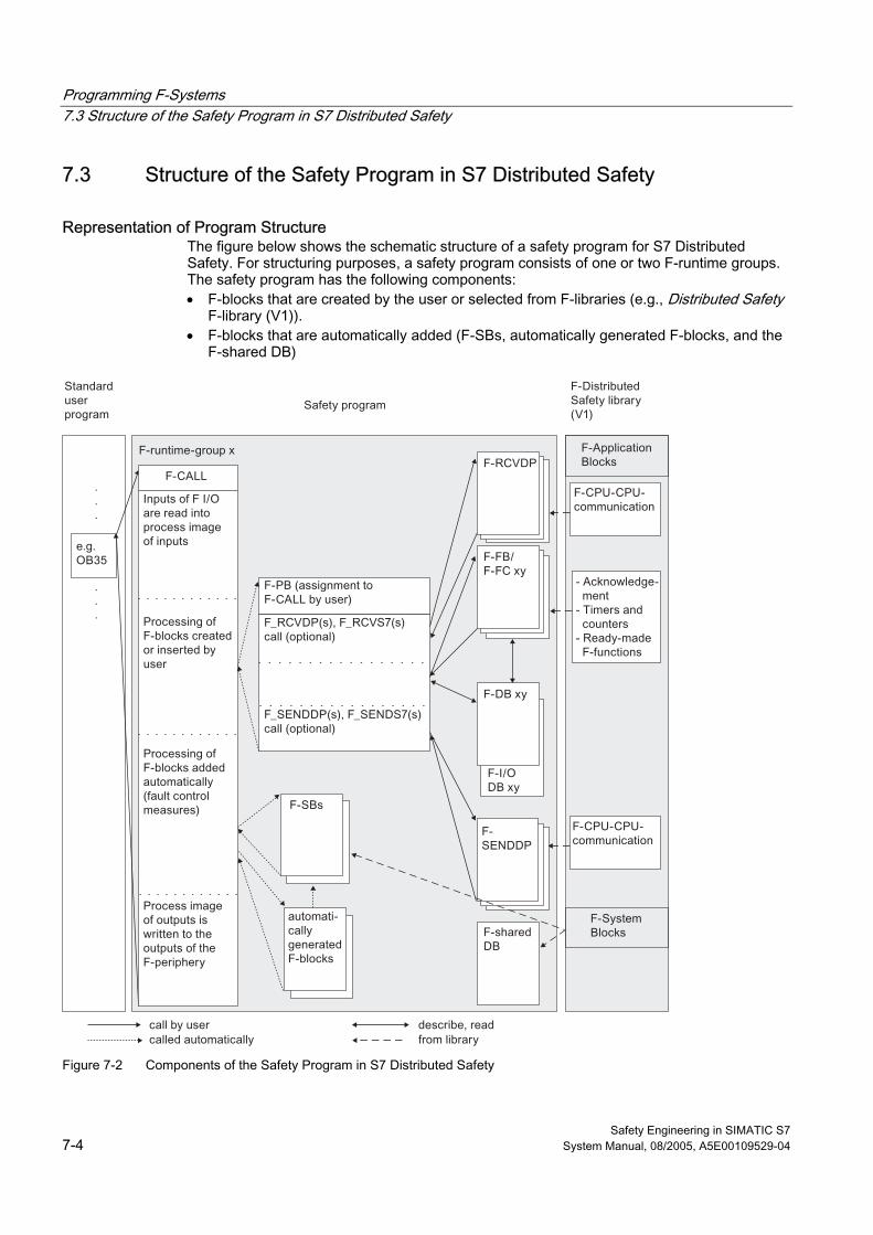
Programming F-Systems 7.3 Structure of the Safety Program in S7 Distributed Safety
Safety Engineering in SIMATIC S7 7-4 System Manual, 08/2005, A5E00109529-04
7.3 7.3 Structure of the Safety Program in S7 Distributed Safety
Representation of Program Structure The figure below shows the schematic structure of a safety program for S7 Distributed Safety. For structuring purposes, a safety program consists of one or two F-runtime groups. The safety program has the following components: • F-blocks that are created by the user or selected from F-libraries (e.g., Distributed Safety
F-library (V1)). • F-blocks that are automatically added (F-SBs, automatically generated F-blocks, and the
F-shared DB)
Figure 7-2 Components of the Safety Program in S7 Distributed Safety
Programming F-Systems 7.3 Structure of the Safety Program in S7 Distributed Safety
Safety Engineering in SIMATIC S7 System Manual, 08/2005, A5E00109529-04 7-5
Description of Program Structure The safety program is accessed by calling F-CALL from the standard user program. F-CALL is called in an OB, preferably in a time interrupt OB (e.g., OB 35).
The advantage of time interrupt OBs is that they interrupt the cyclic program execution in OB 1 of the standard user program at fixed time intervals. That is, the safety program is called and run at fixed time intervals in a time interrupt OB.
Once the safety program is executed, the standard user program resumes.
Structure of the Safety Program in F-Runtime Groups To make it easier to handle, a safety program is formed from one or two "F-runtime groups." An F-runtime group is a logical construct made of several related F-blocks.
An F-runtime group in the safety program for S7 Distributed Safety consists of:
• One F-CALL F-call block
• One F-program block (an F-FB/F-FC assigned to the F-CALL)
• Additional F-FBs or F-FCs programmed using F-FBD or F-LAD, as needed
• One or more F-DBs, as needed
• F-I/O DBs
• F-blocks of the Distributed Safety F-library (V1)
• F-blocks from custom F-libraries
• F-system blocks
• Automatically generated F-blocks
If the user divides his safety program into two F-runtime groups, portions of the safety program (one F-runtime group) can be executed in a faster priority class, thereby achieving faster safety circuits with short response times.
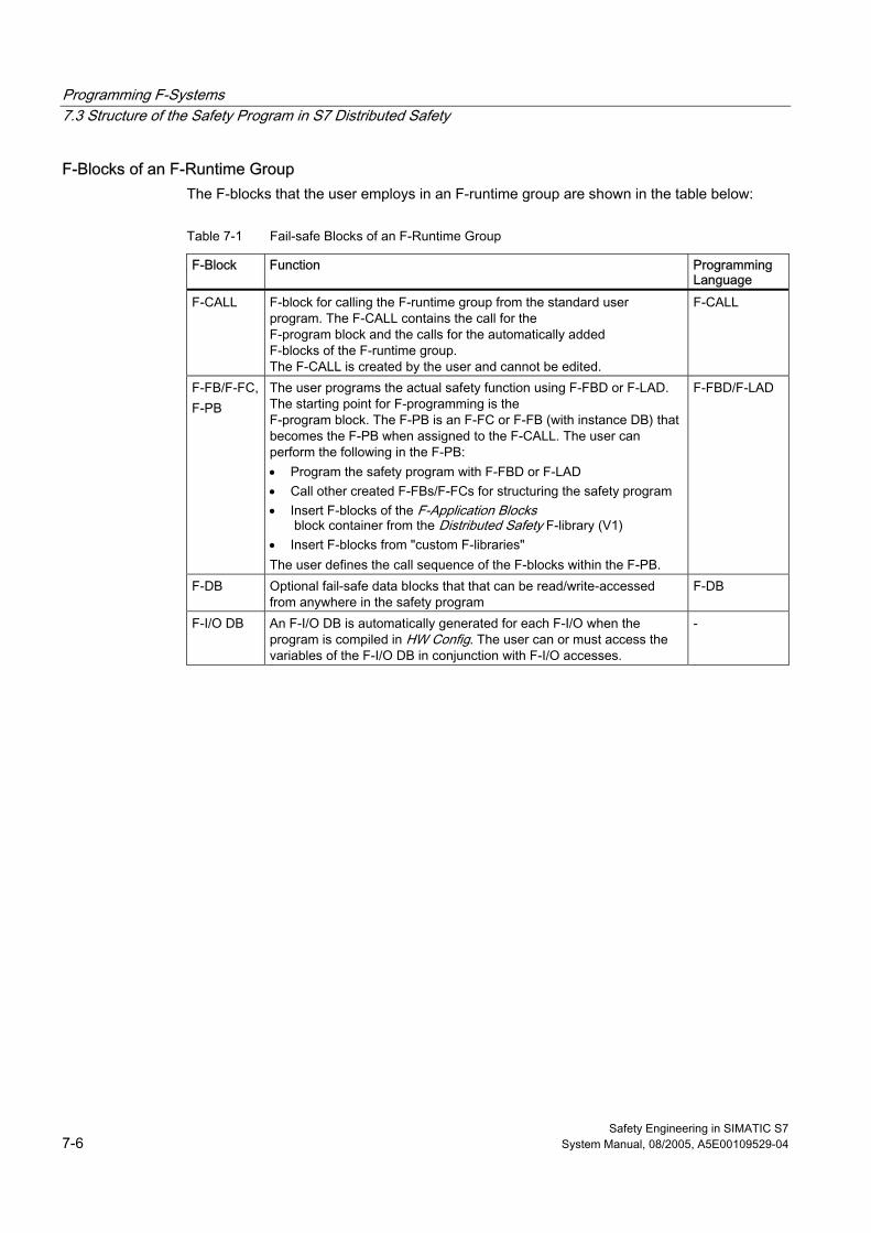
Programming F-Systems 7.3 Structure of the Safety Program in S7 Distributed Safety
Safety Engineering in SIMATIC S7 7-6 System Manual, 08/2005, A5E00109529-04
F-Blocks of an F-Runtime Group The F-blocks that the user employs in an F-runtime group are shown in the table below:
Table 7-1 Fail-safe Blocks of an F-Runtime Group
F-Block Function Programming Language
F-CALL F-block for calling the F-runtime group from the standard user program. The F-CALL contains the call for the F-program block and the calls for the automatically added F-blocks of the F-runtime group. The F-CALL is created by the user and cannot be edited.
F-CALL
F-FB/F-FC,F-PB
The user programs the actual safety function using F-FBD or F-LAD. The starting point for F-programming is the F-program block. The F-PB is an F-FC or F-FB (with instance DB) that becomes the F-PB when assigned to the F-CALL. The user can perform the following in the F-PB: • Program the safety program with F-FBD or F-LAD • Call other created F-FBs/F-FCs for structuring the safety program • Insert F-blocks of the F-Application Blocks
block container from the Distributed Safety F-library (V1) • Insert F-blocks from "custom F-libraries" The user defines the call sequence of the F-blocks within the F-PB.
F-FBD/F-LAD
F-DB Optional fail-safe data blocks that that can be read/write-accessed from anywhere in the safety program
F-DB
F-I/O DB An F-I/O DB is automatically generated for each F-I/O when the program is compiled in HW Config. The user can or must access the variables of the F-I/O DB in conjunction with F-I/O accesses.
-
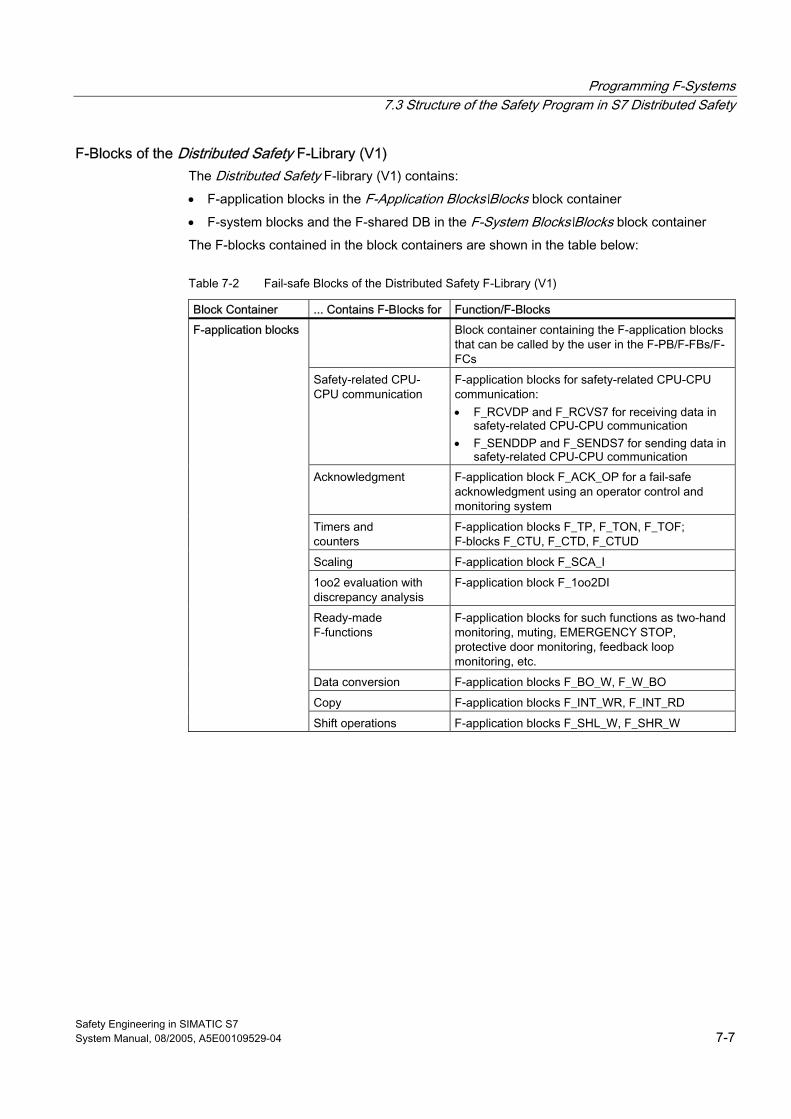
Programming F-Systems 7.3 Structure of the Safety Program in S7 Distributed Safety
Safety Engineering in SIMATIC S7 System Manual, 08/2005, A5E00109529-04 7-7
F-Blocks of the Distributed Safety F-Library (V1) The Distributed Safety F-library (V1) contains:
• F-application blocks in the F-Application Blocks\Blocks block container
• F-system blocks and the F-shared DB in the F-System Blocks\Blocks block container
The F-blocks contained in the block containers are shown in the table below:
Table 7-2 Fail-safe Blocks of the Distributed Safety F-Library (V1)
Block Container ... Contains F-Blocks for Function/F-Blocks Block container containing the F-application blocks
that can be called by the user in the F-PB/F-FBs/F-FCs
Safety-related CPU-CPU communication
F-application blocks for safety-related CPU-CPU communication: • F_RCVDP and F_RCVS7 for receiving data in
safety-related CPU-CPU communication • F_SENDDP and F_SENDS7 for sending data in
safety-related CPU-CPU communication Acknowledgment F-application block F_ACK_OP for a fail-safe
acknowledgment using an operator control and monitoring system
Timers and counters
F-application blocks F_TP, F_TON, F_TOF; F-blocks F_CTU, F_CTD, F_CTUD
Scaling F-application block F_SCA_I
1oo2 evaluation with discrepancy analysis
F-application block F_1oo2DI
Ready-made F-functions
F-application blocks for such functions as two-hand monitoring, muting, EMERGENCY STOP, protective door monitoring, feedback loop monitoring, etc.
Data conversion F-application blocks F_BO_W, F_W_BO
Copy F-application blocks F_INT_WR, F_INT_RD
F-application blocks
Shift operations F-application blocks F_SHL_W, F_SHR_W
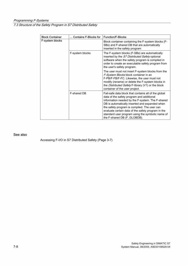
Programming F-Systems 7.3 Structure of the Safety Program in S7 Distributed Safety
Safety Engineering in SIMATIC S7 7-8 System Manual, 08/2005, A5E00109529-04
Block Container ... Contains F-Blocks for Function/F-Blocks Block container containing the F-system blocks (F-
SBs) and F-shared DB that are automatically inserted in the safety program
F-system blocks The F-system blocks (F-SBs) are automatically inserted by the S7 Distributed Safety optional software when the safety program is compiled in order to create an executable safety program from the user's safety program. The user must not insert F-system blocks from the F-System Blocks block container in an F-PB/F-FB/F-FC. Likewise, the user must not modify (rename) or delete the F-system blocks in the Distributed Safety F-library (V1) or the block container of the user project.
F-system blocks
F-shared DB Fail-safe data block that contains all of the global data of the safety program and additional information needed by the F-system. The F-shared DB is automatically inserted and expanded when the safety program is compiled. The user can evaluate certain data of the safety program in the standard user program using the symbolic name of the F-shared DB (F_GLOBDB).
See also Accessing F-I/O in S7 Distributed Safety (Page 3-7)
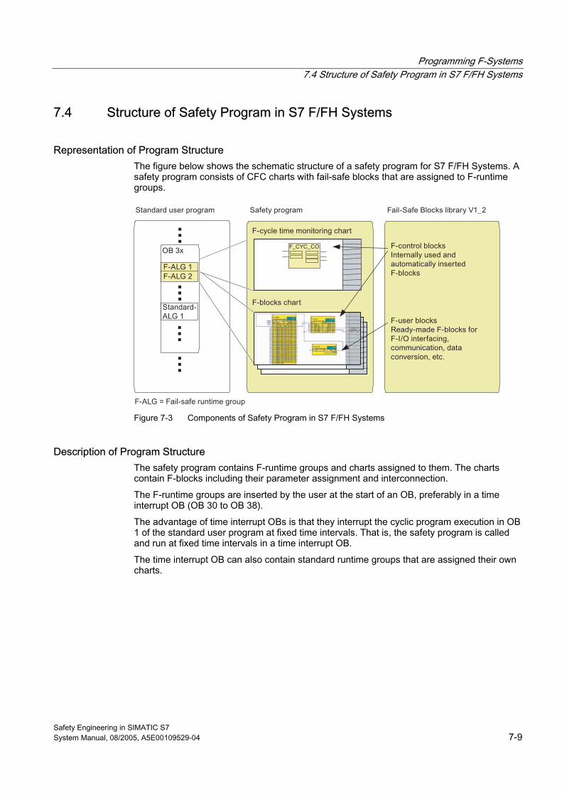
Programming F-Systems 7.4 Structure of Safety Program in S7 F/FH Systems
Safety Engineering in SIMATIC S7 System Manual, 08/2005, A5E00109529-04 7-9
7.4 7.4 Structure of Safety Program in S7 F/FH Systems
Representation of Program Structure The figure below shows the schematic structure of a safety program for S7 F/FH Systems. A safety program consists of CFC charts with fail-safe blocks that are assigned to F-runtime groups.
Figure 7-3 Components of Safety Program in S7 F/FH Systems
Description of Program Structure The safety program contains F-runtime groups and charts assigned to them. The charts contain F-blocks including their parameter assignment and interconnection.
The F-runtime groups are inserted by the user at the start of an OB, preferably in a time interrupt OB (OB 30 to OB 38).
The advantage of time interrupt OBs is that they interrupt the cyclic program execution in OB 1 of the standard user program at fixed time intervals. That is, the safety program is called and run at fixed time intervals in a time interrupt OB.
The time interrupt OB can also contain standard runtime groups that are assigned their own charts.
Programming F-Systems 7.4 Structure of Safety Program in S7 F/FH Systems
Safety Engineering in SIMATIC S7 7-10 System Manual, 08/2005, A5E00109529-04
Continuous Function Charts (CFC) of Safety Program At least two continuous function charts (CFC) are needed for the safety program as follows:
• One chart for F-cycle time monitoring for each time interrupt OB with F-runtime groups (automatically inserted by S7 F Systems in a separate F-runtime group in the safety program when the safety program is compiled)
• One or more charts for the remaining F-blocks of the safety program
The user selects the F-blocks from the "F-User Blocks" block container of the Failsafe Blocks F-library, inserts them in a chart, assigns parameters for them, and interconnects them to other F-blocks.
Fail-safe Blocks of Failsafe Blocks F-Library (V1_2) The Failsafe Blocks F-library (V1_2) contains the following block containers:
• F-user blocks
• F-control blocks
• F-simulation blocks
The F-blocks contained in the block containers are shown in the table below:
Table 7-3 Fail-safe Blocks of Failsafe Blocks F-Library (V1_2)
Block Container ... Contains F-Blocks Function Block container containing the
F-blocks that the user can place in the CFC, assign parameters for, and interconnect.
F-drivers • F_CH_DI • F_CH_AI • F_CH_DO
Channel drivers for the input and output signals of the F-I/O
Conversion F-blocks for data conversion between the standard user program and safety program
• F_BO_FBO • F_I_FI • F_R_FR • F_TI_FTI
Conversion of standard data types to F-data types
• F_FBO_BO • F_FI_I • F_FR_R • F_FTI_TI
Conversion of F-data types to standard data types
• F_FR_FI Conversion of F-data type to F-data type
• F_CHG_R • F_CHG_BO
Safety Data Write
F-user blocks
F_QUITES Fail-safe acknowledgment via an operator control and monitoring system
Programming F-Systems 7.4 Structure of Safety Program in S7 F/FH Systems
Safety Engineering in SIMATIC S7 System Manual, 08/2005, A5E00109529-04 7-11
Block Container ... Contains F-Blocks Function F-system blocks • F_S_BO, F_S_R • F_S_BO, F_S_R
Communication between F-runtime groups
• F_START Signals a cold start or a restart (warm restart)
• F_PSG_M Division in selective runtime groups Communication • F_SENDBO, F_SENDR • F_RCVBO, F_RCVR
F-blocks for safety-related CPU-CPU communication
F-user blocks
Mathematical standard functions F-blocks for mathematical standard functions such as arithmetic, logic, multiplexing, etc.
F-control blocks • F_CYC_CO • F_M_AI6 • F_M_DI24 • F_M_DI8 • F_M_DO10 • F_M_DO8 • F_PLK • F_PLK_O • F_SHUTDN • F_CHG_WS • ...
Block container containing F-blocks that are called and inserted by S7 F Systems when the safety program is compiled, in order to generate an executable safety program from the user's safety program. The user must not insert F-blocks of the F-control block in the safety program. Likewise, the F-blocks must not be modified (renamed) or deleted in the Failsafe Blocks F-library (V1_2) or the block container of the user project.
F-simulation blocks Simulation blocks During offline simulation with PLCSim, the F-blocks of the safety program are overwritten by identically-named simulation blocks from the Failsafe Blocks F-library (V1_2). These F-blocks are suitable for simulation purposes only and must not be downloaded to the F-CPU.

Programming F-Systems 7.4 Structure of Safety Program in S7 F/FH Systems
Safety Engineering in SIMATIC S7 7-12 System Manual, 08/2005, A5E00109529-04
Safety Engineering in SIMATIC S7 System Manual, 08/2005, A5E00109529-04 A-1
A Monitoring and Response Times of F-Systems AA.1 A.1 Introduction
Overview This chapter provides the following information for S7 Distributed Safety and S7 F/FH Systems:
• F-related monitoring times that must be configured
• Rules to be followed when specifying monitoring times
• Formulas to be used when calculating F-specific minimum monitoring times and where to find the necessary time information
• Location where F-related monitoring times are to be entered
• Rules to be followed with calculating the maximum response time of a safety function
Support for Calculations To assist you in approximating the F-specific minimum monitoring times and maximum response times for your F-system, Microsoft Excel files are available for each F-system as follows:
• For S7 Distributed Safety an Excel calculation file is available in the Internet at: http://support.automation.siemens.com/WW/view/en/11669702/133100
• For S7 F/FH Systems: in ...\Siemens\STEP7\S7BIN\S7ftimeb.xls directory
Additional Information The monitoring and response times for the standard portion are calculated in S7 Distributed Safety and S7 F/FH Systems in exactly the same way as for standard S7-300 and S7-400 automation systems and are not addressed here. For a description of this calculation, refer to the hardware manuals for the CPUs.
Monitoring and Response Times of F-Systems A.2 Configuring the Monitoring Times
Safety Engineering in SIMATIC S7 A-2 System Manual, 08/2005, A5E00109529-04
A.2 A.2 Configuring the Monitoring Times
Configuring the Monitoring Times for F-Systems Monitoring times for the safety program are configured similarly in S7 Distributed Safety and S7 F/FH Systems. That is, in some cases you enter the monitoring times as F-block parameters and in STEP 7 dialogs, as described in the following sections. For monitoring communication between the F-CPU and F-I/O, you configure the monitoring times in HW Config in the object properties dialog for the applicable F-modules, F-SMs, fail-safe DP standard slaves or fail-safe I/O standard devices.
Rules for Configuring Monitoring Times When configuring monitoring times, you must take into account the availability as well as the safety of the F-system as follows:
• Availability: To ensure that the temporal monitoring is not triggered when there is no error, the monitoring times selected must be sufficiently long.
• Safety: To ensure that the process safety time is not exceeded, the monitoring times selected must be sufficiently short.
Warning
In order for pulses to be reliably detected, the time interval between two signal changes (pulse duration) must be greater than the corresponding monitoring time.
General Procedure for Configuring Monitoring Times Use the following procedure for configuring monitoring times:
1. Configure the standard or H-system. Refer to the applicable hardware manuals and online help systems for needed information.
2. Configure the specific monitoring times of the F-system with respect to availability. Approximation formulas for calculating the minimum monitoring time are presented below in the respective sections on monitoring times or in the following:
– For S7 Distributed Safety an Excel calculation file is available in the Internet at: http://support.automation.siemens.com/WW/view/en/11669702/133100 .
– For S7 F/FH Systems: in ...\Siemens\STEP7\S7BIN\S7ftimeb.xls directory
3. Use these MS Excel files to calculate the maximum response time and ensure that the process safety time is not exceeded. If necessary, reduce the specific monitoring times of the F-system.
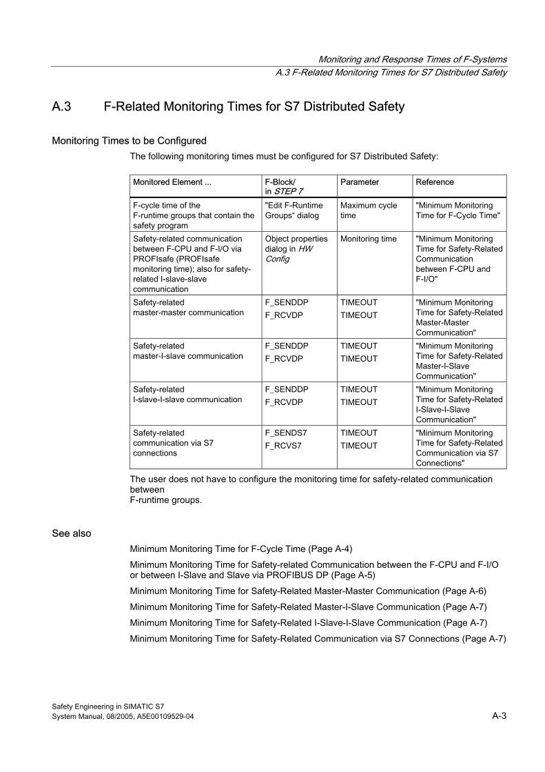
Monitoring and Response Times of F-Systems A.3 F-Related Monitoring Times for S7 Distributed Safety
Safety Engineering in SIMATIC S7 System Manual, 08/2005, A5E00109529-04 A-3
A.3 A.3 F-Related Monitoring Times for S7 Distributed Safety
Monitoring Times to be Configured The following monitoring times must be configured for S7 Distributed Safety:
Monitored Element ... F-Block/
in STEP 7 Parameter Reference
F-cycle time of the F-runtime groups that contain the safety program
"Edit F-Runtime Groups“ dialog
Maximum cycle time
"Minimum Monitoring Time for F-Cycle Time"
Safety-related communication between F-CPU and F-I/O via PROFIsafe (PROFIsafe monitoring time); also for safety-related I-slave-slave communication
Object properties dialog in HW Config
Monitoring time "Minimum Monitoring Time for Safety-Related Communication between F-CPU and F-I/O"
Safety-related master-master communication
F_SENDDP F_RCVDP
TIMEOUT TIMEOUT
"Minimum Monitoring Time for Safety-Related Master-Master Communication"
Safety-related master-I-slave communication
F_SENDDP F_RCVDP
TIMEOUT TIMEOUT
"Minimum Monitoring Time for Safety-Related Master-I-Slave Communication"
Safety-related I-slave-I-slave communication
F_SENDDP F_RCVDP
TIMEOUT TIMEOUT
"Minimum Monitoring Time for Safety-Related I-Slave-I-Slave Communication"
Safety-related communication via S7 connections
F_SENDS7 F_RCVS7
TIMEOUT TIMEOUT
"Minimum Monitoring Time for Safety-Related Communication via S7 Connections"
The user does not have to configure the monitoring time for safety-related communication between F-runtime groups.
See also Minimum Monitoring Time for F-Cycle Time (Page A-4)
Minimum Monitoring Time for Safety-related Communication between the F-CPU and F-I/O or between I-Slave and Slave via PROFIBUS DP (Page A-5)
Minimum Monitoring Time for Safety-Related Master-Master Communication (Page A-6)
Minimum Monitoring Time for Safety-Related Master-I-Slave Communication (Page A-7)
Minimum Monitoring Time for Safety-Related I-Slave-I-Slave Communication (Page A-7)
Minimum Monitoring Time for Safety-Related Communication via S7 Connections (Page A-7)
Monitoring and Response Times of F-Systems A.3 F-Related Monitoring Times for S7 Distributed Safety
Safety Engineering in SIMATIC S7 A-4 System Manual, 08/2005, A5E00109529-04
A.3.1 Minimum Monitoring Time for F-Cycle Time
Maximum Cycle Time Parameter The monitoring time for the F-cycle time can be specified in the "Edit F-Runtime Groups" dialog.
To ensure that monitoring of F-cycle time does not respond when no faults are present causing the F-CPU to go to STOP mode, the "maximum cycle time" parameter setting must be greater than the maximum cycle time of the associated OB.
Extending the Maximum Cycle Time Using CiR: If "Configuration in RUN (CiR)" is used, the maximum cycle time is extended by the lesser of the following two values:
• CiR synchronization time of F-CPU
The CiR synchronization time of the F-CPU is the sum of the CiR synchronization times for all DP master systems that are to be changed simultaneously. The CiR synchronization time of a DP master system is displayed in HW Config in the Properties dialog for the relevant CiR object.
• Upper limit of CiR synchronization time
The default value for the upper limit is 1 s. You can increase or decrease this value according to your requirements by calling SFC 104 "CiR".
Additional Information on CiR and Maximum Cycle Time • STEP 7 online help: "System Changes during Operation Using CiR" • SIMATIC System Software for S7-300/400 System and Standard Functions manual
• For instructions on determining the maximum cycle time, refer to the manual for the F-CPU you are using
Determining Runtime of the Safety Program The runtime of the safety program can be calculated with the aid of an Excel file. The Excel file is available on the Internet at http://support.automation.siemens.com/WW/view/en/11669702/133100.

Monitoring and Response Times of F-Systems A.3 F-Related Monitoring Times for S7 Distributed Safety
Safety Engineering in SIMATIC S7 System Manual, 08/2005, A5E00109529-04 A-5
A.3.2 Minimum Monitoring Time for Safety-related Communication between the F-CPU and F-I/O or between I-Slave and Slave via PROFIBUS DP
PROFIsafe Monitoring Time TPSTO To ensure that monitoring does not respond when no faults are present, the selected PROFIsafe monitoring time TPSTO must be sufficiently large:
TPSTO > TCImax + TFPROG + 2 ☓ TDP_DLY + 2 ☓ TTR + 2 ☓ TSlave + TACK
Definition of Times
Time Definition Reference
TCImax Maximum cycle time of relevant OB
"Minimum Monitoring Time for F-Cycle Time"
TFPROG Maximum runtime of safety program1
-
TDP_DLY Additional DP time delay of a PROFIBUS CP (communications processor)
In HW Config: Object properties for CP, "Operating Mode" tab
TTR Maximum target rotation time for the DP master system (relevant for distributed F-I/O only)
In HW Config: Object properties for DP master system, Bus parameters
TSlave Only relevant for distributed F-I/O in ET 200M, ET 200S and ET 200pro: Maximum response time of distributed I/O system, that is, maximum delay by the IM and its backplane bus
Refer to the manuals for F-I/O to learn about how to calculate these times.
TACK Maximum acknowledgment time of F-I/O (for F-SMs: in safety mode)
You can find this time in the technical specifications of the manuals for the fail-safe modules or SMs.
1 Only relevant for fail-safe I/O with inputs or outputs
Check to Determine If Configured PROFIsafe Monitoring Time Is Too Short Refer to the information in the corresponding section on "Minimum Monitoring Time for Safety-Related Communication between F-CPU and F-I/O" for S7 F/FH systems.
Communication between F-CPU and F-I/O via PROFINET IO Use the Microsoft Excel file provided with S7 Distributed Safety to calculate the minimum monitoring time for PROFINET IO. The Excel file is available on the Internet under the contribution ID 19138505 at http://support.automation.siemens.com/WW/view/en/11669702/133100.
Read also the comments in the Excel file.
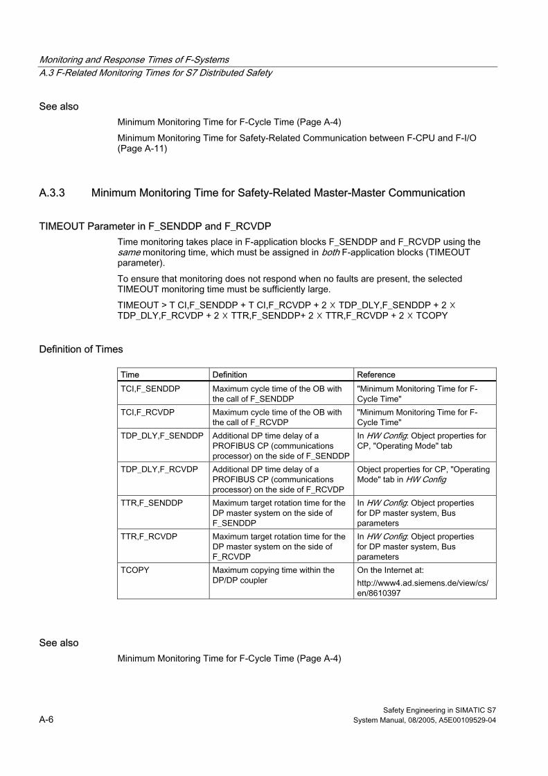
Monitoring and Response Times of F-Systems A.3 F-Related Monitoring Times for S7 Distributed Safety
Safety Engineering in SIMATIC S7 A-6 System Manual, 08/2005, A5E00109529-04
See also Minimum Monitoring Time for F-Cycle Time (Page A-4)
Minimum Monitoring Time for Safety-Related Communication between F-CPU and F-I/O (Page A-11)
A.3.3 Minimum Monitoring Time for Safety-Related Master-Master Communication
TIMEOUT Parameter in F_SENDDP and F_RCVDP Time monitoring takes place in F-application blocks F_SENDDP and F_RCVDP using the same monitoring time, which must be assigned in both F-application blocks (TIMEOUT parameter).
To ensure that monitoring does not respond when no faults are present, the selected TIMEOUT monitoring time must be sufficiently large.
TIMEOUT > T CI,F_SENDDP + T CI,F_RCVDP + 2 ☓ TDP_DLY,F_SENDDP + 2 ☓ TDP_DLY,F_RCVDP + 2 ☓ TTR,F_SENDDP+ 2 ☓ TTR,F_RCVDP + 2 ☓ TCOPY
Definition of Times
Time Definition Reference
TCI,F_SENDDP Maximum cycle time of the OB with the call of F_SENDDP
"Minimum Monitoring Time for F-Cycle Time"
TCI,F_RCVDP Maximum cycle time of the OB with the call of F_RCVDP
"Minimum Monitoring Time for F-Cycle Time"
TDP_DLY,F_SENDDP Additional DP time delay of a PROFIBUS CP (communications processor) on the side of F_SENDDP
In HW Config: Object properties for CP, "Operating Mode" tab
TDP_DLY,F_RCVDP Additional DP time delay of a PROFIBUS CP (communications processor) on the side of F_RCVDP
Object properties for CP, "Operating Mode" tab in HW Config
TTR,F_SENDDP Maximum target rotation time for the DP master system on the side of F_SENDDP
In HW Config: Object properties for DP master system, Bus parameters
TTR,F_RCVDP Maximum target rotation time for the DP master system on the side of F_RCVDP
In HW Config: Object properties for DP master system, Bus parameters
TCOPY Maximum copying time within the DP/DP coupler
On the Internet at: http://www4.ad.siemens.de/view/cs/en/8610397
See also Minimum Monitoring Time for F-Cycle Time (Page A-4)
Monitoring and Response Times of F-Systems A.3 F-Related Monitoring Times for S7 Distributed Safety
Safety Engineering in SIMATIC S7 System Manual, 08/2005, A5E00109529-04 A-7
A.3.4 Minimum Monitoring Time for Safety-Related Master-I-Slave Communication
TIMEOUT Parameter in F_SENDDP and F_RCVDP Time monitoring takes place in F-application blocks F_SENDDP and F_RCVDP using the same monitoring time, which must be assigned in both F-application blocks (TIMEOUT parameter).
To ensure that monitoring does not respond when no errors are present, the selected TIMEOUT monitoring time must be sufficiently large.
TIMEOUT > T CI,F_SENDDP + T CI,F_RCVDP + 2 x TDP_DLY + 2 x TTR
Definition of Times
Time Definition Reference TCI,F_SENDDP Maximum cycle time of the OB with the
call of F_SENDDP "Minimum Monitoring Time for F-Cycle Time"
TCI,F_RCVDP Maximum cycle time of the OB with the call of F_RCVDP
"Minimum Monitoring Time for F-Cycle Time"
TDP_DLY Additional DP time delay of a PROFIBUS CP (communications processor)
Object Properties of CP, "Operating Mode" tab in HW Config
TTR Maximum target rotation time for the DP master system
In HW Config: Object Properties for DP master system, Bus parameters
A.3.5 Minimum Monitoring Time for Safety-Related I-Slave-I-Slave Communication The information provided in "Minimum Monitoring Time for Safety-Related Master-I-Slave Communication" applies here.
A.3.6 Minimum Monitoring Time for Safety-Related Communication via S7 Connections
TIMEOUT Parameter in F_SENDS7 and F_RCVS7 Time monitoring takes place in F-application blocks F_SENDS7 and F_RCVS7 using the same monitoring time, which must be assigned in both F-application blocks (TIMEOUT parameter).
To ensure that monitoring does not respond when no errors are present, the selected TIMEOUT monitoring time must be sufficiently large.
Use the Microsoft Excel file provided with S7 Distributed Safety to determine a recommended TIMEOUT monitoring time for PROFINET IO. The Excel file is available on the Internet under the contribution ID 19138505 at http://support.automation.siemens.com/WW/view/en/11669702/133100.
Monitoring and Response Times of F-Systems A.4 F-Related Monitoring Times for S7 F/FH Systems
Safety Engineering in SIMATIC S7 A-8 System Manual, 08/2005, A5E00109529-04
A.3.7 Monitoring Time for Safety-Related Communication between F-Runtime Groups The monitoring time for safety-related communication between F-runtime groups is determined automatically from the values for the "maximum cycle time" ("Edit F-Runtime Groups" dialog).
Monitoring time = Maximum cycle time of the 1st F-runtime group + maximum cycle time of the 2nd F-runtime group
A.4 A.4 F-Related Monitoring Times for S7 F/FH Systems
Monitoring Times to be Configured The following monitoring times must be configured for S7 F/FH Systems:
Monitored Element ... F-Block/
in HW Config Parameter Reference ...
F-cycle time of the time interrupt OB that contains the safety program
F_CYC_CO MAX_CYC "Minimum Monitoring Time for F-Cycle Time"
Safety-related communication between F-CPU and F-I/O via PROFIsafe (PROFIsafe monitoring time)
Object properties dialog in HW Config
"Monitoring time" "Minimum Monitoring Time for Safety-Related Communication between F-CPU and F-I/O"
Safety-related communication between F-CPUs
F_RCVR, F_RCVBO F_SENDR, F_SENDBO
TIMEOUT "Minimum Monitoring Time for Safety-Related Communication between F-CPUs"
Safety-related communication between F-runtime groups
F_R_R F_R_BO
TIMEOUT "Minimum Monitoring Time for Safety-Related Communication between F-Runtime Groups"
See also Minimum Monitoring Time for F-Cycle Time (Page A-9)
Minimum Monitoring Time for Safety-Related Communication between F-CPU and F-I/O (Page A-11)
Minimum Monitoring Time for Safety-Related Communication between F-CPUs (Page A-13)
Minimum Monitoring Time for Safety-Related Communication between F-Runtime Groups (Page A-14)
Monitoring and Response Times of F-Systems A.4 F-Related Monitoring Times for S7 F/FH Systems
Safety Engineering in SIMATIC S7 System Manual, 08/2005, A5E00109529-04 A-9
A.4.1 Minimum Monitoring Time for F-Cycle Time
MAX_CYC Parameter in F_CYC_CO The monitoring time is assigned in the MAX_CYC input parameter of F-block F_CYC_CO. The F_CYC_CO F-block is automatically inserted by S7 F Systems in a separate F-runtime group in the safety program when the safety program is compiled. When the F_CYC_CO block is positioned, a dialog box is displayed for entering the MAX_CYC parameter.
To ensure that monitoring does not respond when no errors are present, the selected MAX_CYC must be greater than the maximum cycle time of the associated TCImax time interrupt OB:
MAX_CYC > TCImax
The maximum cycle time of the associated TCImax time interrupt OB is at least as large as the configured cycle time of the TCI time interrupt OB . In S7 FH Systems, the maximum disabling time for priority classes > 15 (TP15) must also be taken into account when updating.
Extending the Maximum Cycle Time Using CiR: If "Configuration in RUN (CiR)" is used, the maximum cycle time is extended by the lesser of the following two values:
• CiR synchronization time of F-CPU
The CiR synchronization time of the F-CPU is the sum of the CiR synchronization times for all DP master systems that are to be changed simultaneously. The CiR synchronization time of a DP master system is displayed in HW Config in the properties dialog for the relevant CiR object.
• Upper limit of CiR synchronization time
The default value for the upper limit is 1 s. You can increase or decrease this value according to your requirements by calling SFC 104 "CiR".
Thus, the following approximation formulas are applicable:
Formula Where? TCImax ≈ TCI + MIN(TCiR; 2500)2 In S7 F-Systems TCImax ≈ MAX (TCI; TP15)1 + MIN(TCiR; 2500)2 In S7 FH Systems with time interrupt OB
with special handling TCImax ≈ TCI + TP15 + MIN(TCiR; 2500)2 In S7 FH Systems with time interrupt OB
without special handling 1Use the greater of the two values 2Use the lesser of the two values
Monitoring and Response Times of F-Systems A.4 F-Related Monitoring Times for S7 F/FH Systems
Safety Engineering in SIMATIC S7 A-10 System Manual, 08/2005, A5E00109529-04
Definition of Times
Time Definition Reference TCI Configured cycle time for the time interrupt
OB In HW Config: Object properties for CPU, "Time interrupt, Type"
TP15 Maximum lockout time for priority classes > 15
In HW Config: Object properties for CPU, "H-parameters"
TCiR CiR synchronization time of F-CPU: Sum of CiR synchronization times for all DP master systems that are to be changed simultaneously.
In HW Config: Object properties for CiR object If CiR is not used, enter "0" in the formulas.
Time Interrupt OB with Special Handling A "time interrupt OB" with special handling is an H-parameter of the F-CPU in S7 FH Systems. This parameter includes the number of the time interrupt OB that is called specially when the operating system updates the reserve once all interrupts are disabled. In general, the number entered is the highest priority time interrupt OB to which F-blocks of the safety program are assigned in CFC.
Note To ensure that monitoring of the maximum disabling time for priority classes > 15 is enabled, you must assign a value to this parameter in the "H-Parameters" tab of the object properties for the CPU in HW Config.
Further Information on CiR • STEP 7 online help: "System Changes during Operation Using CiR"
• SIMATIC System Software for S7-300/400 System and Standard Functions manual
• Programmable Controllers S7 F/FH manual
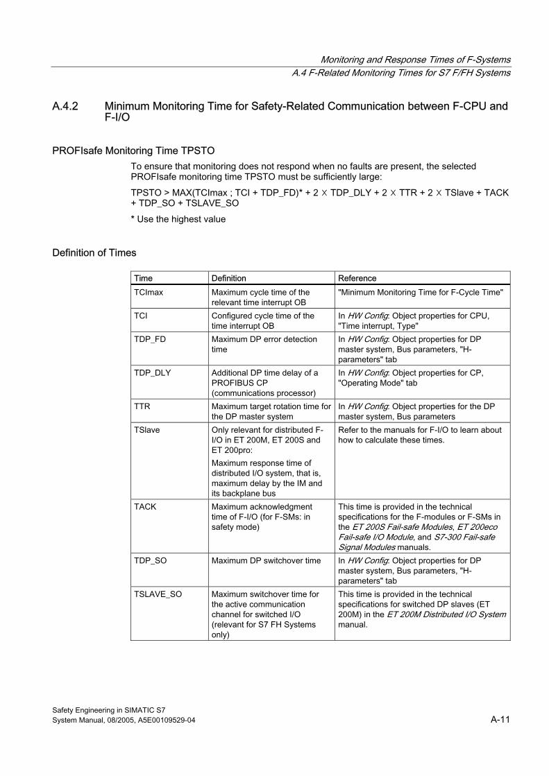
Monitoring and Response Times of F-Systems A.4 F-Related Monitoring Times for S7 F/FH Systems
Safety Engineering in SIMATIC S7 System Manual, 08/2005, A5E00109529-04 A-11
A.4.2 Minimum Monitoring Time for Safety-Related Communication between F-CPU and F-I/O
PROFIsafe Monitoring Time TPSTO To ensure that monitoring does not respond when no faults are present, the selected PROFIsafe monitoring time TPSTO must be sufficiently large:
TPSTO > MAX(TCImax ; TCI + TDP_FD)* + 2 ☓ TDP_DLY + 2 ☓ TTR + 2 ☓ TSlave + TACK + TDP_SO + TSLAVE_SO
* Use the highest value
Definition of Times
Time Definition Reference TCImax Maximum cycle time of the
relevant time interrupt OB "Minimum Monitoring Time for F-Cycle Time"
TCI Configured cycle time of the time interrupt OB
In HW Config: Object properties for CPU, "Time interrupt, Type"
TDP_FD Maximum DP error detection time
In HW Config: Object properties for DP master system, Bus parameters, "H-parameters" tab
TDP_DLY Additional DP time delay of a PROFIBUS CP (communications processor)
In HW Config: Object properties for CP, "Operating Mode" tab
TTR Maximum target rotation time for the DP master system
In HW Config: Object properties for the DP master system, Bus parameters
TSlave Only relevant for distributed F-I/O in ET 200M, ET 200S and ET 200pro: Maximum response time of distributed I/O system, that is, maximum delay by the IM and its backplane bus
Refer to the manuals for F-I/O to learn about how to calculate these times.
TACK Maximum acknowledgment time of F-I/O (for F-SMs: in safety mode)
This time is provided in the technical specifications for the F-modules or F-SMs in the ET 200S Fail-safe Modules, ET 200eco Fail-safe I/O Module, and S7-300 Fail-safe Signal Modules manuals.
TDP_SO Maximum DP switchover time In HW Config: Object properties for DP master system, Bus parameters, "H-parameters" tab
TSLAVE_SO Maximum switchover time for the active communication channel for switched I/O (relevant for S7 FH Systems only)
This time is provided in the technical specifications for switched DP slaves (ET 200M) in the ET 200M Distributed I/O System manual.
Monitoring and Response Times of F-Systems A.4 F-Related Monitoring Times for S7 F/FH Systems
Safety Engineering in SIMATIC S7 A-12 System Manual, 08/2005, A5E00109529-04
Check to Determine If Configured PROFIsafe Monitoring Time Is Too Short
Note During commissioning of the F-system, you can perform a check in safety mode to determine whether the configured PROFIsafe monitoring time is too short. This check is useful if you want to ensure that the configured monitoring time exceeds the minimum monitoring time by a sufficient amount. In this way, you can avoid any sporadic monitoring time errors.
Procedure: 1. Insert an F-I/O (one that will not be needed later for system operation).
2. Assign a shorter monitoring time for this F-I/O than for the F-I/O of the system.
3. If the added F-I/O fails and the "monitoring time for safety message frame exceeded" diagnostic is signaled, you have fallen below the minimum possible PROFIsafe monitoring time.
4. Increase the monitoring time for the added F-I/O just to the point where it no longer fails. This monitoring time corresponds approximately to the minimum possible monitoring time.
Conditions:
The F-I/O to be inserted and the F-I/O whose PROFIsafe monitoring time is to be checked must have the following properties in common: • They must be inserted in the same rack • Stations must be on the same DP subnet • They must be addressed by F-driver blocks in the same F-runtime group
Tip:
It may be useful to leave the added F-I/O in place for systems that will be modified or expanded during operation after commissioning. This F-I/O will then provide an early warning in the event of changes in the time behavior, enabling you to avoid a process shutdown triggered by the F-I/O in the process.
See also Minimum Monitoring Time for F-Cycle Time (Page A-9)
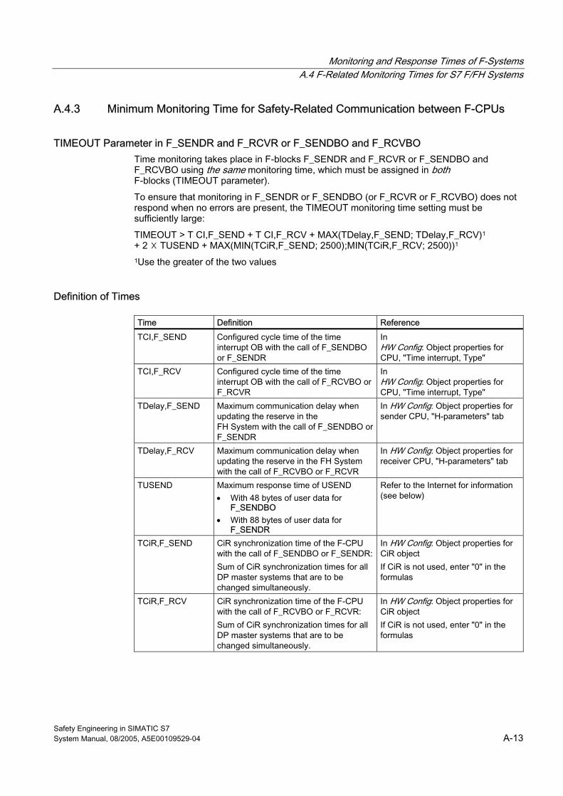
Monitoring and Response Times of F-Systems A.4 F-Related Monitoring Times for S7 F/FH Systems
Safety Engineering in SIMATIC S7 System Manual, 08/2005, A5E00109529-04 A-13
A.4.3 Minimum Monitoring Time for Safety-Related Communication between F-CPUs
TIMEOUT Parameter in F_SENDR and F_RCVR or F_SENDBO and F_RCVBO Time monitoring takes place in F-blocks F_SENDR and F_RCVR or F_SENDBO and F_RCVBO using the same monitoring time, which must be assigned in both F-blocks (TIMEOUT parameter).
To ensure that monitoring in F_SENDR or F_SENDBO (or F_RCVR or F_RCVBO) does not respond when no errors are present, the TIMEOUT monitoring time setting must be sufficiently large:
TIMEOUT > T CI,F_SEND + T CI,F_RCV + MAX(TDelay,F_SEND; TDelay,F_RCV)1 + 2 ☓ TUSEND + MAX(MIN(TCiR,F_SEND; 2500);MIN(TCiR,F_RCV; 2500))1 1Use the greater of the two values
Definition of Times
Time Definition Reference TCI,F_SEND Configured cycle time of the time
interrupt OB with the call of F_SENDBO or F_SENDR
In HW Config: Object properties for CPU, "Time interrupt, Type"
TCI,F_RCV Configured cycle time of the time interrupt OB with the call of F_RCVBO or F_RCVR
In HW Config: Object properties for CPU, "Time interrupt, Type"
TDelay,F_SEND Maximum communication delay when updating the reserve in the FH System with the call of F_SENDBO or F_SENDR
In HW Config: Object properties for sender CPU, "H-parameters" tab
TDelay,F_RCV Maximum communication delay when updating the reserve in the FH System with the call of F_RCVBO or F_RCVR
In HW Config: Object properties for receiver CPU, "H-parameters" tab
TUSEND Maximum response time of USEND • With 48 bytes of user data for
F_SENDBO • With 88 bytes of user data for
F_SENDR
Refer to the Internet for information (see below)
TCiR,F_SEND CiR synchronization time of the F-CPU with the call of F_SENDBO or F_SENDR: Sum of CiR synchronization times for all DP master systems that are to be changed simultaneously.
In HW Config: Object properties for CiR object If CiR is not used, enter "0" in the formulas
TCiR,F_RCV CiR synchronization time of the F-CPU with the call of F_RCVBO or F_RCVR: Sum of CiR synchronization times for all DP master systems that are to be changed simultaneously.
In HW Config: Object properties for CiR object If CiR is not used, enter "0" in the formulas
Monitoring and Response Times of F-Systems A.4 F-Related Monitoring Times for S7 F/FH Systems
Safety Engineering in SIMATIC S7 A-14 System Manual, 08/2005, A5E00109529-04
Determining TUSEND A tool for calculating the TUSEND value is available online at the Internet address below (article ID 1651770):
http://www4.ad.siemens.de/view/cs/en/1651770
Note To enable monitoring of the maximum communication delay when the reserve is updated in S7 FH Systems, you must assign a value to this parameter in HW Config, Object properties for the CPU, "H-Parameters" tab.
Simultaneous updating in both F-CPUs is not assumed.
A.4.4 Minimum Monitoring Time for Safety-Related Communication between F-Runtime Groups
TIMEOUT Parameter in F_R_BO or F_R_R Time monitoring takes place in F-blocks F_R_BO or F_R_R and is assigned in the TIMEOUT input parameter.
To ensure that time monitoring does not respond when no faults are present, the selected TIMEOUT monitoring time must be at least as large as the greater of the two maximum time interrupt cycle times for F_S_R or F_S_BO and F_R_R or F_R_BO:
TIMEOUT > MAX (TClmax, F_S; TCImax, F_R)1 1TIMEOUT > than the greater of the two values
Definition of Times
Time Definition Reference TCImax, F_S Maximum cycle time of the time interrupt OB
with the call of F_S_BO or F_S_R see "Minimum Monitoring Times for F-Cycle Time"
TCImax, F_R Maximum cycle time of the time interrupt OB with the call of F_R_BO or F_R_R
see "Minimum Monitoring Times for F-Cycle Time"
See also Minimum Monitoring Time for F-Cycle Time (Page A-9)
Monitoring and Response Times of F-Systems A.5 Response Times of Safety Functions
Safety Engineering in SIMATIC S7 System Manual, 08/2005, A5E00109529-04 A-15
A.5 A.5 Response Times of Safety Functions
Definition of Response Time The response time starts with the detection of an input signal and ends with the modification of a gated output signal.
Fluctuation Range The actual response time lies between a minimum and maximum response time. You must always take the maximum response time into account in your system configuration.
Rules for Maximum Response Time of a Safety Function The maximum response time of a safety function must be less than the process safety time of the process.
Definition of Process Safety Time The process safety time is the time interval during which the process can be left on its own without causing injury to operating personnel or damage to the environment.
Within the process safety time, any type of F-system process control is tolerated. That is, during this time, the F-system can control its process incorrectly or it can even exercise no control at all. The process safety time of a process depends on the process type and must be determined on a case-by-case basis.
Procedure for Response Time Calculation A formula is available for calculating the maximum response time of a safety function:
• For S7 Distributed Safety on the Internet at http://support.automation.siemens.com/WW/view/en/11669702/133100.
• For S7 F/FH Systems: in ...\Siemens\STEP7\S7BIN\S7ftimeb.xls directory
Use one of these MS Excel files to calculate the maximum response time of the safety function and ensure that the process safety time is not exceeded. If necessary, reduce the specific F-system monitoring times (see "F-Related Monitoring Times for S7 Distributed Safety" and "F-Related Monitoring Times for S7 F/FH Systems").

Monitoring and Response Times of F-Systems A.5 Response Times of Safety Functions
Safety Engineering in SIMATIC S7 A-16 System Manual, 08/2005, A5E00109529-04
Safety Engineering in SIMATIC S7 System Manual, 08/2005, A5E00109529-04 Glossary-1
Glossary
1oo1 evaluation -> 1oo1 Evaluation
1oo1 Evaluation 1oo1 evaluation is a type of -> sensor evaluation in which one sensor is connected via one channel to the ->F-I/O.
1oo2 evaluation -> 1oo2 Evaluation
1oo2 Evaluation 1oo2 evaluation is a type of -> sensor evaluation in which two input channels are occupied, either by one two-channel sensor or two single-channel sensors. The input signals are compared internally for equivalence or non-equivalence.
Access Protection -> Fail-safe systems must be protected from dangerous, unauthorized access. Access protection for -> F-systems is implemented through assignment of two passwords (for the -> F-CPU and the -> safety program).
Actuators Actuators can be power relays or contactors for switching on loads, or they can be loads themselves (for example, directly controlled solenoid valves).
Automatically Generated F-Blocks S7 Distributed Safety: These -> F-blocks are generated automatically when the -> safety program is compiled and are called, if necessary, to generate an executable safety program from the user's safety program.
Availability Availability is the probability that a system is functional at a specific point in time. Availability can be increased through -> redundancy (for example, by using redundant F-I/O and/or by using multiple -> sensors at the same measuring point).
Glossary
Safety Engineering in SIMATIC S7 Glossary-2 System Manual, 08/2005, A5E00109529-04
Category Category in accordance with EN 954-01
-> S7 Distributed Safety and S7 F/FH Systems fail-safe systems can be used in-> safety mode up to Category 4.
CFC Continuous Function Chart
1. CFC is a function chart with graphical interconnection of technological functions (blocks).
2. CFC provides a software package (CFC editor) for technology-oriented, graphics-based configuration of an automation task. CFC is used to create an overall software structure (continuous function chart) from ready-made blocks.
Channel Fault A channel fault is a channel-related fault, such as a wire break or a short circuit.
Channel-selective Passivation With this type of passivation, only the affected channel is passivated when a -> channel fault occurs. If a fault occurs in the -> F-I/O, all channels of the F-I/O are passivated.
CiR CiR (Configuration in RUN) refers to a system modification during operation. A system modification in RUN mode by means of CiR enables configuration changes to be made in RUN mode in portions of the system with distributed I/O. The process is thereby halted for a brief, assignable time period. The process inputs retain their last value during this time period.
Continuous Function Chart (CFC) A continuous function chart consists of up to 26 subcharts containing 6 pages each. Functions (blocks) are interconnected and parameterized on a continous function chart.
Control System A control system is a system that combines and displays higher-level functions of individual distributed control systems.
CRC Cyclic Redundancy Check -> CRC signature
CRC Signature The validity of the process data in the -> safety message frame, the accuracy of the assigned address references, and the safety-related parameters are protected via a CRC signature contained in the safety message frame.
Glossary
Safety Engineering in SIMATIC S7 System Manual, 08/2005, A5E00109529-04 Glossary-3
Custom F-Libraries F-libraries created by the user containing F-FBs, F-FCs, and application templates (network templates).
Dark Period Dark periods occur during switch-off tests and during complete bit pattern tests. Test-related 0 signals are switched from the fail-safe output module to the output bit while the output is active. The output is then switched off briefly (dark period). A sufficiently slow actuator does not respond to this and remains switched on.
Deactivated Safety Mode Deactivated safety mode refers to the temporary deactivation of -> safety mode for test purposes, commissioning, etc.
Whenever safety mode is deactivated, the safety of the system must be ensured by other organizational measures, such as operational monitoring and manual safety shutdown.
Depassivation -> Reintegration
Discrepancy Analysis Discrepancy analysis for equivalence or non-equivalence is used for fail-safe inputs to detect errors based on the timing of two signals with the same functionality. The discrepancy analysis starts when different levels (when checking for non-equivalence: the same level) are detected for two related input signals. A check is made to determine whether the difference (when checking for non-equivalence: the match) has disappeared after expiration of a specified time known as the discrepancy time. If not, this means that a discrepancy error exists.
There are two types of discrepancy analyses for fail-safe input modules:
• In the case of -> 1oo2 evaluation:
The discrepancy analysis is carried out between the two input signals of the -> 1oo2 evaluation in the fails-safe input module.
• In the case of redundant I/O (S7 FH systems only):
The discrepancy analyses is carried out between the two input signals of the redundant input modules by the fail-safe driver blocks of the S7 F Systems optional software.
Discrepancy Time Discrepancy time is a period of time assigned for the -> discrepancy analysis. If the discrepancy time is set too high, the fault detection time and the -> fault reaction time are extended unnecessarily. If the discrepancy time is set too low, availability is decreased unnecessarily because a discrepancy error is detected when, in reality, no error exists.
Glossary
Safety Engineering in SIMATIC S7 Glossary-4 System Manual, 08/2005, A5E00109529-04
DP/DP Coupler The DP/DP coupler is a device for coupling two PROFIBUS DP subnets required for -> safety-related master-master communication between -> safety programs in different -> F-CPUs in S7 Distributed Safety.
Two (or more) F-CPUs are involved in safety-related master-master communication via a DP/DP coupler. Each F-CPU is linked to the DP/DP coupler via its PROFIBUS DP interface.
ES Engineering System (ES): An engineering system is a PC-based configuration system that enables convenient, visual adaptation of the process control system to the task at hand.
Expert A system is generally approved, that is, the safety acceptance test of the system is usually carried out by an independent expert (for example, from TÜV).
Fail-safe DP Standard Slaves Fail-safe DP standard slaves are standard slaves that are operated on PROFIBUS with the DP protocol. Their behavior must comply with IEC 61784-1:2002 Ed1 CP 3/1 and the PROFIsafe bus profile. A GSD file is used to configure fail-safe DP standard slaves.
Fail-safe I/O Module A fail-safe I/O module is an ET 200eco I/O module that can be used for safety-related operation (in -> safety mode) in S7 Distributed Safety or S7 F/FH Systems fail-safe systems. This I/O module is equipped with integrated -> safety functions.
These modules are equipped with integrated -> safety functions.
Fail-safe IO Standard Devices Fail-safe IO standard devices are standard devices that are operated on PROFINET with the IO protocol. They respond according to the standard IEC 61784-1:2002 Ed1 CP 3/3 and the PROFIsafe bus profile in V2 mode. A GSDML file is used to configure them.
Fail-safe Modules ET 200S and und ET 200pro modules that can be used for safety-related operation (-> safety mode) in the ET 200S distributed I/O system or the ET 200pro distributed I/O device. These modules are equipped with integrated -> safety functions.
Fail-safe Systems Fail-safe systems (F-systems) are systems that remain in a safe state or immediately switch to another safe state when certain failures occur.
Glossary
Safety Engineering in SIMATIC S7 System Manual, 08/2005, A5E00109529-04 Glossary-5
F-Application Blocks S7 Distributed Safety: Block container in the Distributed Safety F-library containing F-application blocks.
F-blocks (F-FBs, F-FCs) with ready made functions in the Distributed Safety F-library. The F-application blocks can be called by the user in the -> F-PB and in additional -> F-FBs and -> F-FCs.
F-Attribute S7 Distributed Safety: All -> F-blocks associated with the -> safety program have an F-attribute (identified in the "Safety Program" dialog by an "F" in the F-block symbol). Once the -> safety program has been compiled successfully, only the blocks of the -> safety program have an F-attribute.
Fault Reaction Function -> User safety function
Fault Reaction Time The maximum fault reaction time for an F-system is the time between the occurrence of any fault and a safe reaction at all affected fail-safe outputs. For the overall F-System: The maximum fault reaction time is the time between the occurrence of any fault in any F-I/O and a safe reaction at the associated fail-safe output.
For inputs: The maximum fault reaction time is the time between the occurrence of the fault and the safe response on the backplane bus.
For digital outputs: The maximum fault reaction time is the time between the occurrence of the fault and the safe response at the digital output.
F-Blocks Fail-safe blocks of the -> safety program
F-CALL S7 Distributed Safety: "F-call block" for the -> safety program. The F-CALL is created by the user as an FC in the "F-CALL" programming language; "F-CALL" cannot be edited. The F-CALL calls the -> F-runtime group from the -> standard user program. It contains the call for the -> F-PB and the calls for the automatically added F-blocks (-> F-SBs, -> automatically generated F-blocks, -> F-shared DB) of the F-runtime group.
F-Channel Drivers S7 F/FH Systems: F-channel drivers provide process data in a safe format. The user must position and interconnect the F-channel drivers in the -> safety program.
F-Communication DBs S7 Distributed Safety: Fail-safe data blocks used for safety-related CPU-CPU communication via S7 connections.
Glossary
Safety Engineering in SIMATIC S7 Glossary-6 System Manual, 08/2005, A5E00109529-04
F-Control Blocks S7 F/FH Systems: Block container of the Failsafe Blocks F-library, which contains the -> F-blocks that are automatically called/added during compiling of the -> safety program in order to generate an executable safety program from the safety program programmed by the user.
F-CPU An F-CPU is a central processing unit with fail-safe capability that is permitted for use in S7 Distributed Safety/S7 F/FH Systems. For S7 F/FH systems, the F-Runtime license allows the central processing unit to be used as an F-CPU. That is, it can execute a safety program. For S7 Distributed Safety, an F-Runtime license is not required. A -> standard user program can also be run in the F-CPU.
F-Data Type S7 F/FH Systems: A -> standard user program and -> safety program use different data formats. Safety-related F-data types are used in the safety program.
F-DBs S7 Distributed Safety: Optional fail-safe data blocks that can be read and written to within the entire -> safety program.
F-Driver Block The F-driver block is used for inputting/outputting AS values from/to the -> F-I/O. It forms the software interface to the process, converts the physical values to process data (and vice-versa), and also provides information about the availability of the hardware addressed.
In S7 F/FH Systems, -> safety-related communication takes place using inputs and outputs of F-driver blocks. The user must position and interconnect special F-driver blocks in -> continuous function charts (CFC) of the -> F-runtime group.
F-FBD Programming language for -> safety programs in S7 Distributed Safety. The standard FBD/LAD Editor in STEP 7 is used for programming.
F-FBs S7 Distributed Safety: Fail-safe function blocks (with instance DBs), in which the user programs the -> safety program in -> F-FBD or -> F-LAD.
F-FCs S7 Distributed Safety: Fail-safe FCs, in which the user programs the -> safety program in -> F-FBD or -> F-LAD.
Glossary
Safety Engineering in SIMATIC S7 System Manual, 08/2005, A5E00109529-04 Glossary-7
F-I/O F-I/O is a group designation for fail-safe inputs and outputs available in SIMATIC S7 for integration in S7 Distributed Safety and S7 F/FH Systems fail-safe systems. The following F-I/O are available:
• -> ET 200eco fail-safe I/O module
• S7-300 fail-safe signal modules (-> F-SMs)
• -> Fail-safe modules ET 200S and ET 200pro (ET 200pro for S7 Distributed Safety only)
• -> Fail-safe DP standard slaves (for S7 Distributed Safety only)
• -> Fail-safe IO standard devices (for S7 Distributed Safety only)
F-I/O DB S7 Distributed Safety: Fail-safe data block for -> F-I/O in an -> F-CPU in S7 Distributed Safety. An F-I/O DB is automatically generated for each F-I/O when the program is compiled in HW Config. The F-I/O DB contains variables that the user can evaluate in the -> safety program, or that he can or must write to:
• For reintegration of the F-I/O following communication errors, F-I/O faults, or channel faults
• If the F-I/O must be passivated as a result of particular states of the safety program (for example, group passivation)
• For reassigning parameters of -> fail-safe DP standard slaves
• In order to evaluate whether fail-safe values or process data are output
F-LAD -> F-FBD
F-Module Driver S7 F/FH Systems: The F-module driver ensures -> PROFIsafe communication between the -> safety program and the -> F-I/O. It is automatically positioned and interconnected in the safety program.
F-Modules -> Fail-safe modules
F-PB S7 Distributed Safety: "Introductory F-block" for fail-safe programming of the -> safety program. The F-PB is an -> F-FB or -> F-FC that the user assigns to the -> F-CALL of the -> F-runtime group.
The F-PB contains the F-FBD or F-LAD safety program, any calls of additional -> F-FBs/F-FCs for program structuring, and any F-application blocks from the -> F-Application Blocks block container of the Distributed Safety F-library.
Glossary
Safety Engineering in SIMATIC S7 Glossary-8 System Manual, 08/2005, A5E00109529-04
F-Runtime Group When the -> safety program is created, the -> F-blocks cannot be inserted directly into tasks/OBs; rather, they must be inserted into F-runtime groups. The safety program consists of one or two F-runtime group (S7 Distributed Safety) or several F-runtime groups (S7 F/FH systems).
F-Runtime License -> F-CPU
F-SBs S7 Distributed Safety: Fail-safe system blocks that are automatically called/inserted when the -> safety program is compiled in order to create an executable safety program from the user's safety program.
F-Shared DB S7 Distributed Safety: Fail-safe data block that contains all of the global data of the -> safety program and additional information needed by the F-system. When the -> safety program is compiled, the F-shared DB is automatically inserted and expanded. Using the symbolic name of the F-shared DB (F_GLOBDB), the user can evaluate certain data from the -> safety program in the -> standard user program.
F-Simulation Blocks S7 F/FH Systems: Block container of the Failsafe Blocks library that contains simulation blocks. During offline simulation with -> PLCSim, the -> F-blocks of the -> safety program are overwritten by simulation blocks from the F-library with the same name.
F-SMs F-SMs are signal modules of S7-300 that can be used for safety-related operation (in -> safety mode) in S7 Distributed Safety or S7 F/FH Systems fail-safe systems. These modules are equipped with integrated -> safety functions.
F-System Blocks S7 Distributed Safety: Block container of the Distributed Safety library containing the -> F-SBs and the -> F-shared DB.
-> F-SB
F-Systems -> Fail-safe systems
Glossary
Safety Engineering in SIMATIC S7 System Manual, 08/2005, A5E00109529-04 Glossary-9
F-User Blocks S7 F/FH Systems: Block container of Failsafe Blocks library containing the -> F-blocks that the user can position, assign parameters to, and interconnect in -> continuous function charts (CFC).
Light Period Light periods occur during complete bit pattern tests. Test-related "1" signals are switched from the fail-safe output module to the output bit while the output is deactivated (output signal "0"). The output is then switched on briefly (light period). A sufficiently slow actuator does not respond to this and remains switched off.
Master-Reserve Switchover In S7 FH Systems, a master-reserve switchover is triggered when the master goes to STOP mode. That is, the system switches from the master CPU to the reserve CPU.
MSR Instrumentation and control technology
Non-equivalent Sensor A non-equivalent -> sensor is a reversing switch that is connected (via two channels) to two inputs of an -> F-I/O in -> fail-safe systems (for -> 1oo2 evaluation of sensor signals).
OBT Optical Bus Terminal (OBT): Equipment used to connect an individual PROFIBUS DP device without an integrated optical interface or an RS 485 segment to the optical PROFIBUS DP.
OLM Optical Link Module (OLM): Equipment used for fiber-optic interfacing to convert electrical signals into optical signals and vice versa.
OP Operator Panel (OP): A programmable HMI device used to operate and monitor machines and systems.
OS Operator Station (OS): A configurable operator station used to operate and monitor machines and systems.
Glossary
Safety Engineering in SIMATIC S7 Glossary-10 System Manual, 08/2005, A5E00109529-04
Passivation If an -> F-I/O detects a fault, it switches either the affected channel or all channels to a -> safe state; that is, the channels of this F-I/O are passivated. The F-I/O reports the detected fault to the -> CPU via the slave diagnostics.
For an F-I/O with inputs, if passivation occurs, the F-system provides fail-safe values for the -> safety program instead of the process data pending at the fail-safe inputs.
For an I/O with outputs, if passivation occurs, the F-system transfers fail-safe values (0) to the fail-safe outputs instead of the output values provided by the safety program.
PCS 7 PCS 7 is a process control system based on selected SIMATIC components that have been optimized for use in a control system. In addition, there are functional enhancements to ensure availability of control-system-specific system behavior and functions required in a process and instrumentation control system from engineering to operation.
Process Safety Time The process safety time is the time interval during which the process can be left on its own without causing injury to operating personnel or damage to the environment.
Within the process safety time, any type of F-system process control is tolerated. That is, during this time, the -> F-system can control its process incorrectly or it can even exercise no control at all. The process safety time depends on the process type and must be determined on a case-by-case basis.
PROFINET IO Within the framework of PROFINET, PROFINET IO is a communication concept for the implementation of modular, distributed applications.
PROFINET IO allows you to create automation solutions familiar from PROFIBUS.
PROFINET IO is implemented based on both the PROFINET standard for automation devices and the STEP 7 engineering tool.
This means that you have the same application view in STEP 7, regardless of whether you are configuring PROFINET or PROFIBUS devices. Programming your user program is essentially the same for PROFINET IO and PROFIBUS DP if you use the expanded blocks and system status lists for PROFINET IO.
PROFINET IO Controller A PROFINET IO controller is a device that is addressed via the connected IO device. That is: that the IO controller exchanges input and output signals with assigned field devices. The IO controller is often the controller on which the automation program runs.
PROFINET IO Device A PROFINET IO device is a decentralized field device that is assigned to one of the IO controllers (e.g., remote IO, valve terminals, frequency converters, switches)
Glossary
Safety Engineering in SIMATIC S7 System Manual, 08/2005, A5E00109529-04 Glossary-11
PROFINET IO Supervisor A PG/PC or HMI device used for commissioning and diagnostics.
PROFINET IO controller with assigned PROFINET IO devices.
PROFIsafe Safety-related PROFIBUS DP/PA and PROFINET IO bus profile for communication between the -> safety program and the -> F-I/O in an -> F-system.
PROFIsafe Address Every -> F-I/O has a PROFIsafe address. The PROFIsafe address must be configured in STEP 7 HW Config and set via a switch on the fail-safe I/O.
PROFIsafe Monitoring Time Minimum monitoring time for safety-related communication between F-CPU and F-I/O
Programming Device (PG) Programming device: Programming devices (PGs) are compact personal computers especially made for use in an industrial setting. A programming device (PG) is fully equipped for programming SIMATIC automation systems.
Proof-test Interval The proof-test interval is the time period after which a component must be put into fail-safe state. That is, it is replaced by an unused component or it is proven to be completely fault-free.
Redundancy, Availability-enhancing Availability-enhancing redundancy refers to redundancy of components with the aim of ensuring that components continue to function even in the event of hardware faults.
Redundancy, Safety-enhancing Safety-enhancing redundancy refers to redundancy of components with the aim of detecting hardware faults by means of comparison; for example, -> 1oo2 evaluation in -> F-I/O.
Redundant Switched I/O Redundant switched I/O is a configuration variant of S7 FH Systems in -> safety mode to increase availability. -> F-CPU, PROFIBUS DP, and -> F-I/O are redundant. In the event of a fault, the F-I/O is no longer available.
Glossary
Safety Engineering in SIMATIC S7 Glossary-12 System Manual, 08/2005, A5E00109529-04
Reintegration Once a fault has been eliminated, the -> F-I/O must be reintegrated (depassivated). The reintegration (switching from fail-safe values to process data) is performed automatically or, alternatively, only after a mandatory user acknowledgment in the safety program.
For an F-I/O with inputs, the process data pending at the fail-safe inputs are provided again for the -> safety program after reintegration. For an F-I/O with outputs, the F-system transfers the output values provided in the safety program to the fail-safe outputs again.
Restart of F-System When an -> F-CPU transitions from STOP to RUN, the -> standard user program restarts as usual. When the -> safety program restarts, data blocks are initialized with values from the load memory as follows:
• S7 Distributed Safety: all data blocks with -> F-attribute
• S7 F/FH Systems: all data blocks
• This occurs analogously to a cold restart. As a result, saved fault information is lost. The -> F-system performs an automatic -> reintegration of the -> F-I/O. In contrast to the standard user program, the startup OBs (OB 100 to 102) cannot be used in the safety program.
S7-PLCSIM S7-PLCSIM allows you to test and edit your program in a simulated automation system on your programming device or PC. Since the simulation takes place completely in STEP 7, you do not need any hardware (CPU, I/O).
Safe State The basic principle of the safety concept in an -> F-system is the existence of a safe state for all process variables. For digital F-I/O, this is the value "0", for example.
Safety Class Safety Integrity Level (SIL) in accordance with IEC 61508 and EN 50129. The higher the Safety Integrity Level the more rigid the measures for prevention of systematic faults and for management of systematic faults and hardware failures.
-> S7 Distributed Safety and S7 F/FH Systems fail-safe systems can be used in -> safety mode up to SIL3.
Safety Function Safety function is a mechanism built into the -> F-CPU and -> F-I/O that allows them to be used in -> S7 Distributed Safety or S7 F/FH Systems fail-safe systems.
In accordance with IEC 61508: Function implemented by a safety device in order to maintain the system in a -> safe state or to place it into a safe state in the event of a particular fault (-> user safety function).
Glossary
Safety Engineering in SIMATIC S7 System Manual, 08/2005, A5E00109529-04 Glossary-13
Safety Message Frame In -> safety mode, data are transferred in a safety message frame between the -> F-CPU and the -> F-I/O or, in safety-related CPU-to-CPU communication, between the F-CPUs.
Safety Mode 1. Safety mode is the operating mode of the -> F-I/O that allows -> safety-related
communication using -> safety message frames. -> Fail-safe modules ET 200S, ET 200pro und ET 200eco are designed for safety mode only. -> F-SMs S7-300 can be used in -> standard mode or safety mode (except SM 326; DO 8 × DC 24V/2A).
2. Operating mode of the -> safety program. In safety mode of the safety program, all safety mechanisms for fault detection and fault reaction are activated. In safety mode, the safety program cannot be modified during operation. Safety mode can be deactivated by the user (-> deactivated safety mode).
Safety Program The safety program is a safety-related user program.
Safety Protector The safety protector protects the -> F-SMs from possible overvoltages in the event of a fault. The safety protector must be used for SIL3/Cat.4 applications:
• Generally, when PROFIBUS DP is configured with copper cable
• When PROFIBUS DP is configured with fiber-optic cable and combined operation of standard signal modules and -> F-SMs in one ET 200M is required
Safety-related Communication Safety-related communication is communication used to exchange fail-safe data.
Sensor Evaluation There are two types of sensor evaluation:
• -> 1oo1 evaluation – Sensor signal is read out once
• -> 1oo2 evaluation – The sensor signal is read twice by the same -> F I/O and compared internally.
Sensors Sensors are used for exact measurement of paths, positions, velocities, rotational speeds, masses, etc.
Glossary
Safety Engineering in SIMATIC S7 Glossary-14 System Manual, 08/2005, A5E00109529-04
Sequence Number Time-monitoring of the message-frame update in the PROFIsafe protocol is performed through the transfer of a sequence number from the -> F-CPU to the -> F-I/O. A valid, current -> safety message frame with a valid sequence number must be received by the F-CPU and the F-I/O within an assignable monitoring time. If a valid sequence number is not detected within the monitoring time, the F-I/O is passivated.
Single-channel I/O Single-channel I/O is a configuration variant of S7 Distributed Safety/S7 F Systems in -> safety mode. The -> F-CPU and -> F-I/O are not redundant. In the event of a fault, the F-I/O is no longer available.
Single-channel Switched I/O Single-channel switched I/O are a configuration variant of S7 FH Systems in -> safety mode to increase availability. The -> F-CPU is redundant and the -> F-I/O is not redundant; in the event of a fault, the system switches over to the other F-CPU. In the event of a fault, the F-I/O is no longer available.
Standard Communication Standard communication is communication used to exchange non-safety-related data.
Standard Mode In standard mode of -> F-I/O, -> safety-related communication using -> safety message frames is not possible; only -> standard communication is possible in this operating mode.
-> S7-300 F-SMs can be used in standard mode or -> safety mode. -> Fail-safe modules ET 200S, ET 200pro und ET 200eco are designed for safety mode only.
Standard User Program The standard user program is a non-safety-related user program.
Test Signals For -> F-I/O with outputs, the required -> safety class is achieved by injecting test signals (-> light period, -> dark period).
User Safety Function The -> safety function for the process can be provided through a user safety function or a fault reaction function. The user only programs the user safety function. If the -> F-system can no longer execute its actual user safety function, it executes the fault reaction function; for example, the associated outputs are deactivated, and the -> F-CPU switches to STOP mode, if necessary.
Glossary
Safety Engineering in SIMATIC S7 System Manual, 08/2005, A5E00109529-04 Glossary-15
Validity Check The validity check checks the signals for validity. It must be ensured that a process data element lies within the limits specified by the user.
In -> F-systems: The user must perform a validity check in the -> safety program to ensure that dangerous conditions cannot arise when data are transferred from a -> standard user program to a safety program.
WinCC WinCC is an industry and technology-neutral system for visualization and control tasks in production and process automation.
WinCC offers industry-standard function modules for graphics representation, messaging, archiving, and logging functions. WinCC ensures high availability with its powerful process interfacing, rapid image updating, and reliable data archiving.

Glossary
Safety Engineering in SIMATIC S7 Glossary-16 System Manual, 08/2005, A5E00109529-04
Safety Engineering in SIMATIC S7 System Manual, 08/2005, A5E00109529-04 Index-1
Index
1 1oo1 evaluation, 5-2, 5-3 1oo2 evaluation, 5-2, 5-5
A Acceptance test
of system, 4-7 Access
to F-I/O, 3-7, 3-10 Access protection, 4-2, 4-7 Acknowledgment
of errors, 3-8, 3-11 Annex 1, 4-8 Application block
F_RCVDP, 3-14, 3-15 F_SENDDP, 3-14, 3-15
Application template Graphics-based, 7-7
Approvals, 4-8 Area of application
S7 Distributed Safety, 1-5 S7 F/FH Systems, 1-6
Automation system Fail-safe, see F-system, 1-1
Availability, 1-7 Increasing, 2-9, 5-4, 5-7, 5-10 Limits with redundant switched I/O, 2-21 Limits with single-channel I/O, 2-14, 2-17 Limits with single-channel switched I/O, 2-19 of F-system, 2-22
B Burner management, 1-5
C Category (Cat.), 2-8, 5-1
Achievable, 1-3, 2-23, 4-12, 5-2, 5-12
Central module, see F-CPU, 1-11 Certificate, 4-8 CFC, 1-16, 3-4, 7-3 Chart, see CFC, 7-9 CiR, A-4, A-9 Coexistence
of fail-safe and standard components, 2-7 Cold restart, 4-6 Collection, vi Combining
of fail-safe and standard components, 2-7 Communication
between F-CPU and F-I/O, 3-6 between F-CPUs, 1-8, 3-13 between F-runtime groups, 3-5 between standard user program and safety program, 3-3 between standard user programs, 3-1 F-blocks for (S7 F/FH systems), 7-11 Monitoring time for, A-5, A-6, A-7, A-11, A-13, A-14 Safety-related, 3-2 Safety-related I-slave-slave communication, 3-8 Standard communication between CPU and F-I/O, 3-11 via S7 connections (Distributed Safety, 3-18 via S7 connections (S7 Distributed Safety, A-7 via S7 connections (S7 F/FH systems, 3-20
Configuration Centralized, 2-10 Distributed, 2-11, 2-13 of F-systems, 2-1 of STEP 7 project, 7-2 S7 Distributed Safety, 2-2 S7 F Systems, 2-5 S7 FH Systems, 2-6
Configuration example S7 Distributed Safety, 2-3 S7 F Systems, 2-6 S7 FH Systems, 2-7
Configuration in RUN, see CiR, A-4, A-9 Configuration options
Depending on availability, 2-9
Index
Safety Engineering in SIMATIC S7 Index-2 System Manual, 08/2005, A5E00109529-04
Configuration variants of F-systems, 2-1
Configuring F-CPU, 6-2 F-I/O, 6-4 Monitoring time, A-2 of F-systems, 6-1 of hardware, 1-10
Continuous Function Chart (CFC), 7-9, 7-10 Continuous mode, 4-13 Control system, 2-22 Conventions
in the system description, vii Conversion
F-blocks (S7 F/FH Systems), 7-10 Conversion block, 3-4 Copper, 2-23
PROFIBUS DP in, 2-15, 2-18, 2-20 CPU 315F-2 DP
Configuring, 6-2 CRC, 4-4 Cycle time
Monitoring time for, A-4, A-9
D Dark period, 5-12 Data block, 3-3 Data conversion, 3-4 Data exchange
between safety program and standard user program, 3-3
Data format, 3-3, 3-4 Data transfer
from standard user program, 3-4, 3-5 from the safety program, 3-4
Data type, 3-4, 3-14, 3-15, 7-3 Deactivated safety mode, 4-3 Demand mode, 4-13, 4-15 Development stage, 1-7 Diagnostic buffer, 3-12 Diagnostic data, 3-12 Diagnostic data record, 3-12 Diagnostic function, 3-11 Direct access, 3-12 Discrepancy analysis, 5-5 Discrepancy time, 5-5 Distributed I/O
Fail-safe, 1-2 Distributed Safety
Library, 7-3, 7-7 Documentation
Additional, v
Documentation packages Order number, v
DP master, 2-3, 2-6, 2-7 DP slave, 2-3, 2-6, 2-7 DP, see Distributed I/O, 1-2 DP/DP coupler, 3-13
E EM 4/8 F-DI 24 VDC
Configuring, 6-4 Emergency STOP devices, 1-5 Error acknowledgment, 3-8, 3-11 ET 200M, 1-12
Restrictions, 1-13 ET 200pro
Fail-safe modules, 1-14 ET 200S
Fail-safe modules, 1-13, 1-14
F F_Application Blocks, 7-7 F_F data type_data type, 3-4 F_RCVDP, 3-14, 3-15, 3-16, 7-7 F_RCVS7, 3-18 F_SENDDP, 3-14, 3-15, 3-16, 7-7 F_SENDS7, 3-18 Fail-safe automation system, see F-system, 1-1 Fail-safe blocks
Library, 3-10, 7-10 Failsafe Blocks
Library, 7-3 Fail-safe distributed I/O, 1-2 Fail-safe DP standard slave, 1-14
Configuring, 6-5 Fail-safe I/O standard devices, 1-14
Configuring, 6-5 Fail-safe I/O, see F-I/O, 1-10 Fail-safe modules, see F-modules, 1-13, 1-14 Fail-safe signal modules, 3-11 Fail-safe signal modules, see F-SM, 1-12 Fail-safe system, see F-system, 1-1 Fail-safe value, 3-8, 3-11 Fault reaction
in F-CPU and operating system, 4-5 in safety program, 1-8, 2-22, 4-5
Fault reaction function, 1-4 Fault-tolerant and fail-safe system, 1-3 Fault-tolerant S7 connections, 3-20
Index
Safety Engineering in SIMATIC S7 System Manual, 08/2005, A5E00109529-04 Index-3
F-block, 7-4 F_F data type_data type, 3-4 for conversion (S7 F/FH Systems), 7-10 Mathematical standard functions (S7 F/FH Systems), 7-11
F-blocks of Distributed Safety library, 7-7 of Failsafe Blocks library, 7-10
F-CALL, 7-6 F-call block, see F-CALL, 7-6 F-channel driver, 3-10 F-channel drivers, 3-10, 7-10 F-control blocks, 7-11 F-CPU, 1-11
Configuring, 6-2 Fault reaction, 4-5 Password for, 4-7
F-CPUs Communication between, 1-8, 3-13
F-cycle time Monitoring time for, A-4, A-9
F-data block, see F-DB, 7-6 F-data type, 3-4 F-DB, 7-6 F-driver block, 3-6, 3-10 F-FB, 7-6 F-FBD, 1-16, 7-3 F-FC, 7-6 F-I/O, 1-10, 1-12
Access, 3-7, 3-10 Applicable, 2-22 Configuring, 6-4 Connection, 1-7, 3-6 Group shutdown, 3-8, 3-11 in safety mode, 4-3 Process data of, 3-7, 3-10
F-I/O DB, 3-8 Fiber-optic cables, 2-8, 2-23
PROFIBUS DP, 2-12, 2-16, 2-18, 2-20 F-LAD, 1-16, 7-3 F-Library, see Library, 3-10 F-module driver, 3-10 F-modules
ET 200pro, 1-14 ET 200S, 1-13, 1-14, 3-11
F-PB, 7-6 F-program block, see F-PB, 7-6 F-runtime group, 3-5, 7-4, 7-5, 7-9
Maximum cycle time, A-8 F-runtime license, 1-11 F-shared DB, 3-3, 3-4, 7-8 F-simulation blocks, 7-11 F-SM, 1-12
Restrictions, 1-13
F-system Available, 1-3 Communication options, see Communication, 3-2 Components, 1-10 Configuring, 2-1, 6-1 Monitoring time, A-1 Operating modes, 4-6 Programming, 7-1 Response time, A-1 Safety in, 4-2 Selection criteria, 2-22 System configuration, 2-23
F-system block, see F-SB, 7-8 F-system blocks, 7-8 FUP, siehe F-FUP, 1-16 F-user blocks, 7-10, 7-11 F-user program, see Safety program, 1-10
G Group shutdown
of F-I/O, 3-8, 3-11 GSD file, 6-5 GSDML file, 6-5 Guide
through system description, vi Guidelines, 4-9
H H/F Competence Center, vii Hardware
Configuring, 1-10 Hardware components
of F-system, 1-11 HOLD, 4-6 HOLD mode, see HOLD, 4-6 Hotline, vii
I I/O connection, 1-7 IEC 61508, 4-13, 4-14 IEC 61508-5, 4-12 Input signals
Safety-related, 1-2 Instance data block, 3-3, 3-8 Instrumentation and control, 1-6 Interface modules
for ET 200S, 1-13
Index
Safety Engineering in SIMATIC S7 Index-4 System Manual, 08/2005, A5E00109529-04
I-slave-I-slave communication, A-7 I-Slave-I-Slave communication, 3-16
K KOP, siehe F-KOP, 1-16
L Library, 3-10
Distributed Safety, 7-3, 7-7 Fail-safe blocks, 7-10 Failsafe Blocks, 7-3 PCS 7 drivers, 3-12
Light period, 5-12
M Machine protection, 1-5 Main areas of application, 1-8 Master-I-slave communication, 3-15, A-7 Master-master communication, 3-14 Master-reserve switchover, 4-5 Mathematical standard functions
F-blocks for (S7 F/FH Systems), 7-11 Maximum cycle time of the F-runtime group, A-8 Memory bits, 3-3, 3-4 Monitoring time, 4-4, A-1
Communication between F-CPU and F-I/O, A-11 Communication between F-CPUs, A-6, A-7, A-13 Configuring, A-2 for communication between F-CPU and F-I/O, A-5 for communication between F-runtime groups, A-14 for communication between I-slaves, A-7 for communication between I-slaves and slaves, A-5 for communication via S7 connections, A-7 for F-cycle time, A-4, A-9 S7 Distributed Safety, A-3 S7 F/FH Systems, A-8 Safety-related master-master communication, A-6
N Network template, see Application template, 7-7 Networks
Public, 3-18, 3-20
Non-equivalence, 5-5 Non-equivalent sensor, 5-7
O OB 1, 7-5, 7-9 OB 100, 4-6 OB 102, 4-6 OB 30 to OB 38
Time interrupt OB, 7-9 OB 35
Time interrupt OB, 7-5 Operating mode change, see RUN, 4-3 Operating modes
of F-system, 4-6 Operating system
Fault reaction, 4-5 Optional package, 1-15 Order numbers
Documentation packages, v DP/DP coupler, 3-13
Organization block, see OB, 4-6 Output signals
Safety-related, 1-2 Overvoltages
Protection from, 2-8
P Passivation, 3-8, 3-11, 4-5 Password, 1-11, 4-2, 6-2
for F-CPU, 4-7 for safety program, 4-7
PCS 7, 1-6, 3-12 PCS 7 drivers
Library, 3-12 Personnel protection, 1-5 Planning
of system, 1-17 PLCSim, 7-11 Probability
of failure of safety function, 4-13 Probability of failure, 4-13
of components of F-systems, 4-15 Process data, 3-8, 3-11, 4-4 Process engineering, 1-6 Process image, 3-3, 3-4, 3-6, 3-7, 3-12 Process industry, 1-5 Process safety time, A-15 PROFIBUS DP, 1-4, 2-3, 3-13
in copper cable technology, 2-15, 2-18, 2-20 in fiber-optic cables, 2-12, 2-16, 2-18, 2-20
PROFINET IO, 1-4, 1-9, 2-3
Index
Safety Engineering in SIMATIC S7 System Manual, 08/2005, A5E00109529-04 Index-5
PROFIsafe, 4-4 Address, 6-2
PROFIsafe bus profile, 1-4 Programming
of F-system, 7-1 Programming language, 1-8, 1-16, 2-22, 7-3 Proof-test interval, 4-15 Protection
from overvoltages, 2-8 Purpose of system description, iii
R Redundancy, 1-3, 2-7, 2-9 Redundant sensor, 5-2 Redundant switched I/O, 2-9, 2-20
Limits of availability, 2-21 References
Additional, v Reintegration, 4-5 Resources
of F-CPU for safety program, 6-2 Response time, A-15
of F-system, 1-7, A-1 Restart, 4-6 Restart OB, 4-6 Restart protection, 4-6 Risk analysis
In accordance with IEC 61508, 4-14 Risk parameters, 4-13 RUN
Modifying safety program, 4-3 RUN mode
Modifying safety program, 1-8 RUN mode, see RUN, 4-3 Runtime
of safety program, A-4 Runtime group, see F-runtime group, 3-5
S S7 connections
Communication via (S7 Distributed Safety), 3-18 Communication via (S7 F/FH Systems), 3-20
S7 Distributed Safety, 1-3, 1-15 Area of application, 1-5 Centralized configuration, 2-10 Components, 2-2 Configuration, 2-2 Configuration example, 2-3 Distributed configuration, 2-11, 2-13 F-related monitoring times, A-3 Probability of failure of components, 4-15
PROFIBUS DP, 2-11 PROFINET IO, 2-13 Program structure, 7-4 S7 connections, A-7 System performance, 1-7
S7 F Systems, 1-15 Components, 2-5 Configuration, 2-5 Configuration example, 2-6
S7 F/FH Systems, 1-3 Area of application, 1-6 F-related monitoring times, A-8 Probability of failure of components, 4-15 Program structure, 7-9 System performance, 1-7
S7 FH Systems, 2-9 Components, 2-6 Configuration, 2-6 Configuration example, 2-7
S7-300 Fail-safe signal modules, 1-12 Fail-safe signal modules Restrictions, 1-13
Safe state, 1-1, 4-5 Safety
in F-systems, 4-2 Safety certificate, 4-8 Safety class, 2-8, 2-23, 5-1
Achievable, 1-3, 1-7, 2-23, 4-12, 5-12 Effect of sensor quality, 5-3
Safety engineering Advantages of integration, 1-2 Integrated, 1-2 Objective, 1-1
Safety function Calculating response time, A-15 Probability of failure, 4-13
Safety functions, 4-2 Principle of, 1-3
Safety Integrated, 1-2 Safety integrity level, 4-12
Achievable, 5-2 Safety Integrity Level
In accordance with IEC 61508, 4-13 Safety mechanisms, 4-1 Safety message frame, 4-3 Safety mode, 3-11
Deactivated, 4-3 of F-I/O, 4-3 of safety program, 4-3
Index
Safety Engineering in SIMATIC S7 Index-6 System Manual, 08/2005, A5E00109529-04
Safety program Communication between F-CPU and F-I/O, 3-6 Communication between F-CPUs, 3-13 Communication between F-runtime groups, 3-5 Communication for standard user program, 3-3 CPU resources for, 6-2 Creating, 1-10 Determining runtime, A-4 Effect on restart characteristics, 4-6 Fault reaction in, 1-8, 4-5 in safety mode, 4-3 Modifying, 1-8 Password for, 4-7 Program structure (S7 Distributed Safety), 7-4 Program structure (S7 F/FH Systems), 7-9 Programming language, 1-16
Safety protector, 2-8 Safety requirements, 4-12 Safety-related communication, see Communication, 3-2 Scope of system description, iii See F-SB, 7-8, 7-11 Selection criteria
for an F-system, 2-22 Sensor
Redundant, 5-2 Single-channel, 5-2 Two-channel, 5-2
Sensor evaluation, 5-1, 5-2 Sensor quality
Effect on safety class, 5-3 Sequence number, 4-3 Sequence of steps
for working with F-systems, 1-18 Service, vii Service information, 3-8, 3-11 SFC 59, 3-12 Signals
Safety-related, 1-2 Single-channel I/O, 2-9, 2-10, 2-15
Limits of availability, 2-14, 2-17 Single-channel sensor, 5-2 Single-channel switched I/O, 2-9, 2-18
Limits of availability, 2-19 Slave diagnostics, 3-12 Software components
of F-system, 1-15 Software redundancy
Software package, 2-9
Standard mode, 3-11 Standard modules, 2-3, 2-6, 2-7 Standard user program, 1-11
Communication between CPU and F-I/O, 3-11 Standards, 4-8, 4-9 STEP 7 project
Schematic structure, 7-2 STOP
of F-CPU, 4-5 STOP mode, see STOP, 4-5 Subnet, 3-13 Support, vii
Additional, vii PROFINET IO, 1-9
System Acceptance test, 4-7 Planning, 1-17
System configuration of F-system, 2-23
System description Contents, vi
System performance of F-systems, 1-7
T Test signals, 5-1, 5-12 Time interrupt OB, 7-5, 7-9 Training center, vii Two-channel sensor, 5-2 Typical response time of F-system, 2-22
U User safety function, 1-4
V Validity check, 3-4, 3-5 Variables
for F-I/O communication, 3-8, 3-11
W Warm restart, 4-6 What's new?, iv WinCC, 3-12
SIMATIC S7 Distributed Safety: feedbackA5E00297771-03
Siemens AG
A&D AS SM IDPostfach 1963D-92209 Amberg
Telefax: +49(9621)80-3103mailto:[email protected]
Your Feedback as regards the S7 Distributed Safety
Dear SIMATIC user,
Our goal is to provide you information with a high degree of quality and usability, and to continuouslyimprove the SIMATIC documentation for you. To achieve this goal, we require your feedback andsuggestions. Please take a few minutes to fill out this questionnaire and return it to me by Fax, e-mail orby post.
We are giving out three presents every month in a raffle among the senders. Which present would youlike to have?
SIMATIC Manual Collection Automation Value Card Laser pointer
Dr. Thomas Rubach,Head of Information & Documentation
General Questions
1. Are you familiar with the SIMATIC ManualCollection?
yes no
2. Have you ever downloaded manuals from theinternet?
yes no
3. Do you use Getting Starteds?
yes no
if yes, which:
4. How much experience do you have with theS7 Distributed Safety?
Expert
Experienced user
Advanced user
Beginner
Your Address:
Name:
Company:
Position:
Street:
Postal code / Place:
Email:
Phone:
Fax:
SIMATIC S7 Distributed Safety: feedbackA5E00297771-03
Please specify the documents, for which you want to answer the questions below:
A: Manual S7 Distributed Safety, D: Manual ET 200eco, Distributed I/O Configuring and Programming Fail-Safe I/O Module
B: Manual S7-300, Fail-Safe E: System DescriptionSignal Modules Safety Engineering in SIMATIC S7
C: Manual ET 200S, Distributed I/O SystemFail-Safe Modules
1. In which project phase do you use thisdocument frequently?
Information Assembly
Planning Commissioning
Configuration Maintenance & Service
Programming others:
2. Finding the required information in thedocument:
� How quickly can you find the desired information inthe document?
immediately not at all
after a brief after a long search search
� Which search method do you prefer?
Table of contents Index
Full-text search others:
� Which supplements/improvements would you like in order to help you find the required information quickly?
3. Your judgement of the document as regardscontent.
� How satisfied are you with this document
Totally satisfied not very satisfied
Very satisfied not satisfied
Satisfied
� Were able to find the required information?
yes no
which was not:
4. What is the scope of the information?
Just right
Not enough - which topic:
Too detailed – which topic:
5. Is the information easy to understand (texts,figures, tables)?
yes no
if no, which was not:
6. Are examples important to you?
no, of less importance
yes, important –were the examplesenough?
yes no
if no, on which topic:
7. What are your suggestions as regards thecontents of the document?
Thank you for your cooperation
F: Getting StartedS7 Distributed Safety
G: ET 200pro Distributed I/O Device -Fail-Safe Modules