Embed Size (px)
Citation preview
Safety Evaluation Report
With Open Items Related to the License Renewal of Diablo Canyon Nuclear Power Plant, Units 1 and 2
Docket Nos. 50-275 and 50-323
Pacific Gas and Electric Company
U.S. Nuclear Regulatory Commission
Office of Nuclear Reactor Regulation
January 2011

iii
ABSTRACT
This safety evaluation report (SER) documents the technical review of the Diablo Canyon Nuclear Power Plant (DCPP), Units 1, and 2, license renewal application (LRA) by the U.S. Nuclear Regulatory Commission (NRC) staff (the staff). By letter dated November 23, 2009, Pacific Gas & Electric Company (PG&E or the applicant) submitted the LRA in accordance with Title 10 of the Code of Federal Regulations, Part 54, “Requirements for Renewal of Operating Licenses for Nuclear Power Plants.” PG&E requests renewal of the DCPP operating licenses (Facility Operating License Numbers DPR-80 and DPR-82) for a period of 20 years beyond the current expiration dates at midnight on November 2, 2024, for Unit 1, and August 26, 2025, for Unit 2.
DCPP is located approximately 12 miles west southwest of San Luis Obispo, CA. The NRC issued the construction permits on April 23, 1968, for Unit 1, and December 9, 1970, for Unit 2. The NRC issued the operating licenses on November 2, 1984, for DCPP Unit 1, and on August 26, 1985, for DCPP Unit 2. DCPP Units 1 and 2 employ a pressurized water reactor (PWR) design with a dry ambient containment. Westinghouse Electric Corporation supplied the nuclear steam supply system. PG&E designed and constructed the balance of the plant with assistance from Bechtel. The licensed power output of each unit is 3,411 megawatt thermal with a gross electrical output of approximately 1,120 megawatt electric.
This SER presents the status of the staff’s review of information submitted through December 13, 2010, which was the cutoff date for consideration in the SER, unless otherwise noted. The staff identified eight open items and two confirmatory item that must be resolved before the staff will make a final determination on the LRA. SER Sections 1.5 and 1.6, for open items and confirmatory items, respectively, summarize these items. The staff will present its final conclusion on the LRA review in an update to this SER.

iv
v
TABLE OF CONTENTS
ABSTRACT ................................................................................................................................... iii
LIST OF TABLES ........................................................................................................................ xiii
ABBREVIATIONS ....................................................................................................................... xv
SECTION 1 INTRODUCTION AND GENERAL DISCUSSION ............................................... 1-1 1.1 Introduction ......................................................................................................... 1-1 1.2 License Renewal Background ............................................................................ 1-2
1.2.1 Safety Review ...................................................................................... 1-3 1.2.2 Environmental Review ......................................................................... 1-4
1.3 Principal Review Matters .................................................................................... 1-4 1.4 Interim Staff Guidance ........................................................................................ 1-6 1.5 Summary of Open Items .................................................................................... 1-6 1.6 Summary of Confirmatory Items ....................................................................... 1-11 1.7 Summary of Proposed License Conditions ...................................................... 1-12
SECTION 2 STRUCTURES AND COMPONENTS SUBJECT TO AGING MANAGEMENT REVIEW ......................................................................................................................... 2-1 2.1 Scoping and Screening Methodology ................................................................. 2-1
2.1.1 Introduction .......................................................................................... 2-1 2.1.2 Summary of Technical Information in the Application.......................... 2-1 2.1.3 Scoping and Screening Program Review ............................................ 2-2
2.1.3.1 Implementation Procedures and Documentation Sources for Scoping and Screening ....................................................... 2-3
2.1.3.2 Quality Controls Applied to License Renewal Application Development ....................................................................... 2-5
2.1.3.3 Training ............................................................................... 2-5 2.1.3.4 Conclusion of Scoping and Screening Program Review ..... 2-6
2.1.4 Plant Systems, Structures, and Components Scoping Methodology .. 2-6 2.1.4.1 Application of the Scoping Criteria in Title 10, Part 54.4(a)(1)
of the Code of Federal Regulations ..................................... 2-6 2.1.4.2 Application of the Scoping Criteria in Title 10, Part 54.4(a)(2)
of the Code of Federal Regulations ................................... 2-12 2.1.4.3 Application of the Scoping Criteria in Title 10, Part 54.4(a)(3)
of the Code of Federal Regulations ................................... 2-21 2.1.4.4 Plant Level Scoping of Systems and Structures ............... 2-24 2.1.4.5 Mechanical Component Scoping ....................................... 2-26 2.1.4.6 Structural Component Scoping ......................................... 2-27 2.1.4.7 Electrical Component Scoping .......................................... 2-28 2.1.4.8 Conclusion for Scoping Methodology ................................ 2-29 2.1.5 Screening Methodology ..................................................... 2-29 2.1.5.1 General Screening Methodology ....................................... 2-29 2.1.5.2 Mechanical Component Screening ................................... 2-31 2.1.5.3 Structural Component Screening ...................................... 2-32 2.1.5.4 Electrical Component Screening ....................................... 2-33 2.1.5.5 Conclusion for Screening Methodology ............................. 2-34
2.1.6 Summary of Evaluation Findings ....................................................... 2-35
vi
2.2 Plant Level Scoping Results ............................................................................. 2-35 2.2.1 Introduction ........................................................................................ 2-35 2.2.2 Summary of Technical Information in the Application........................ 2-35 2.2.3 Staff Evaluation ................................................................................. 2-35 2.2.4 Conclusion ......................................................................................... 2-37
2.3 Scoping and Screening Results: Mechanical Systems .................................... 2-37 2.3.1 Reactor Vessel, Internals, and Reactor Coolant System................... 2-44
2.3.1.1 Reactor Vessel and Internals ............................................ 2-45 2.3.1.2 Reactor Coolant System ................................................... 2-46 2.3.1.3 Pressurizer ........................................................................ 2-47 2.3.1.4 Steam Generators ............................................................. 2-48 2.3.1.5 Reactor Core ..................................................................... 2-49
2.3.2 Engineered Safety Features .............................................................. 2-50 2.3.2.1 Safety Injection System ..................................................... 2-50 2.3.2.2 Containment Spray System ............................................... 2-51 2.3.2.3 Residual Heat Removal System ........................................ 2-52 2.3.2.4 Containment Heating, Ventilation, and Air Conditioning
System .............................................................................. 2-53 2.3.3 Auxiliary Systems .............................................................................. 2-54
2.3.3.1 Cranes and Fuel Handling System .................................... 2-55 2.3.3.2 Spent Fuel Pool Cooling System ....................................... 2-56 2.3.3.3 Saltwater and Chlorination System ................................... 2-56 2.3.3.4 Component Cooling Water System ................................... 2-58 2.3.3.5 Makeup Water System ...................................................... 2-59 2.3.3.6 Nuclear Steam Supply Sampling System .......................... 2-63 2.3.3.7 Compressed Air System .................................................... 2-65 2.3.3.8 Chemical and Volume Control System .............................. 2-68 2.3.3.9 Miscellaneous Heating, Ventilation, and Air Conditioning
Systems ............................................................................. 2-69 2.3.3.10 Control Room Heating, Ventilation, and Air Conditioning
System .............................................................................. 2-70 2.3.3.11 Auxiliary Building Heating, Ventilation, and Air Conditioning
System .............................................................................. 2-71 2.3.3.12 Fire Protection System ...................................................... 2-72 2.3.3.13 Diesel Generator Fuel Oil System ..................................... 2-77 2.3.3.14 Diesel Generator System .................................................. 2-78 2.3.3.15 Lube Oil System ................................................................ 2-81 2.3.3.16 Gaseous Radwaste System .............................................. 2-81 2.3.3.17 Liquid Radwaste System ................................................... 2-82 2.3.3.18 Miscellaneous Systems in Scope Only for Criterion Title 10,
Part 54.4(a)(2) of the Code of Federal Regulations .......... 2-83 2.3.3.19 Oily Water and Turbine Sump System .............................. 2-85
2.3.4 Steam and Power Conversion Systems ............................................ 2-86 2.3.4.1 Turbine Steam Supply System .......................................... 2-87 2.3.4.2 Auxiliary Steam System .................................................... 2-88 2.3.4.3 Feedwater System ............................................................ 2-89 2.3.4.4 Condensate System .......................................................... 2-91 2.3.4.5 Auxiliary Feedwater System .............................................. 2-92
2.4 Scoping and Screening Results: Structures ..................................................... 2-93 2.4.1 Containment Building ........................................................................ 2-94
2.4.1.1 Summary of Technical Information in the Application ....... 2-94 2.4.1.2 Staff Evaluation ................................................................. 2-94
vii
2.4.1.3 Conclusion ......................................................................... 2-95 2.4.2 Control Room .................................................................................... 2-95
2.4.2.1 Summary of Technical Information in the Application ....... 2-95 2.4.2.2 Staff Evaluation ................................................................. 2-95 2.4.2.3 Conclusion ......................................................................... 2-96
2.4.3 Auxiliary Building ............................................................................... 2-96 2.4.3.1 Summary of Technical Information in the Application ....... 2-96 2.4.3.2 Staff Evaluation ................................................................. 2-96 2.4.3.3 Conclusion ......................................................................... 2-97
2.4.4 Turbine Building ................................................................................. 2-97 2.4.4.1 Summary of Technical Information in the Application ....... 2-97 2.4.4.2 Staff Evaluation ................................................................. 2-97 2.4.4.3 Conclusion ......................................................................... 2-98
2.4.5 Radwaste Storage Facilities .............................................................. 2-98 2.4.5.1 Summary of Technical Information in the Application ....... 2-98 2.4.5.2 Staff Evaluation ................................................................. 2-98 2.4.5.3 Conclusion ......................................................................... 2-99
2.4.6 Pipeway Structure ............................................................................. 2-99 2.4.6.1 Summary of Technical Information in the Application ....... 2-99 2.4.6.2 Staff Evaluation ................................................................. 2-99 2.4.6.3 Conclusion ......................................................................... 2-99
2.4.7 Diesel Fuel Oil Pump Vaults and Structures.................................... 2-100 2.4.7.1 Summary of Technical Information in the Application ..... 2-100 2.4.7.2 Staff Evaluation ............................................................... 2-100 2.4.7.3 Conclusion ....................................................................... 2-101
2.4.8 230 Kilovolt Switchyard, 500 Kilovolt Switchyard, and Electrical Foundations and Structures ............................................................ 2-101 2.4.8.1 Summary of Technical Information in the Application ..... 2-101 2.4.8.2 Staff Evaluation ............................................................... 2-101 2.4.8.3 Conclusion ....................................................................... 2-102
2.4.9 Fuel Handling Building ..................................................................... 2-102 2.4.9.1 Summary of Technical Information in the Application ..... 2-102 2.4.9.2 Staff Evaluation ............................................................... 2-102 2.4.9.3 Conclusion ....................................................................... 2-103
2.4.10 Intake Structure and Intake Control Building ................................... 2-103 2.4.10.1 Summary of Technical Information in the Application ..... 2-103 2.4.10.2 Staff Evaluation ............................................................... 2-104 2.4.10.3 Conclusion ....................................................................... 2-104
2.4.11 Earthwork and Yard Structures ....................................................... 2-105 2.4.11.1 Summary of Technical Information in the Application ..... 2-105 2.4.11.2 Staff Evaluation ............................................................... 2-105 2.4.11.3 Conclusion ....................................................................... 2-105
2.4.12 Discharge Structure ......................................................................... 2-105 2.4.12.1 Summary of Technical Information in the Application ..... 2-105 2.4.12.2 Staff Evaluation ............................................................... 2-106 2.4.12.3 Conclusion ....................................................................... 2-106
2.4.13 Outdoor Water Storage Tank Foundations and Encasements ........ 2-106 2.4.13.1 Summary of Technical Information in the Application ..... 2-106 2.4.13.2 Staff Evaluation ............................................................... 2-106 2.4.13.3 Conclusion ....................................................................... 2-106
2.4.14 Supports .......................................................................................... 2-107 2.4.14.1 Summary of Technical Information in the Application ..... 2-107
viii
2.4.14.2 Staff Evaluation ............................................................... 2-107 2.4.14.3 Conclusion ....................................................................... 2-108
2.5 Scoping and Screening Results: Electrical and Instrumentation and Control Systems .......................................................................................................... 2-108 2.5.1 Electrical Component Groups .......................................................... 2-109
2.5.1.1 Summary of Technical Information in the Application ..... 2-109 2.5.1.2 Staff Evaluation ............................................................... 2-110 2.5.1.3 Conclusion ....................................................................... 2-111
2.6 Conclusion for Scoping and Screening .......................................................... 2-111
SECTION 3 AGING MANAGEMENT REVIEW RESULTS ...................................................... 3-1 3.0 Applicant’s Use of the Generic Aging Lessons Learned Report ......................... 3-1
3.0.1 Format of the License Renewal Application ........................................ 3-2 3.0.1.1 Overview of Table 1s ........................................................... 3-2 3.0.1.2 Overview of Table 2s ........................................................... 3-3
3.0.2 Staff’s Review Process ........................................................................ 3-4 3.0.2.1 Review of Aging Management Programs ............................ 3-4 3.0.2.2 Review of Aging Management Review Results ................... 3-5 3.0.2.3 Final Safety Analysis Report Supplement ........................... 3-6 3.0.2.4 Documentation and Documents Reviewed ......................... 3-6
3.0.3 Aging Management Programs ............................................................. 3-7 3.0.3.1 Aging Management Programs Consistent with the Generic
Aging Lessons Learned Report ........................................... 3-9 3.0.3.2 Aging Management Programs Consistent with the Generic
Aging Lessons Learned Report with Exceptions or Enhancements .................................................................. 3-67
3.0.3.3 Aging Management Programs Not Consistent with or Not Addressed in the Generic Aging Lessons Learned
Report .............................................................................. 3-162 3.0.4 QA Program Attributes Integral to Aging Management Programs ... 3-173
3.0.4.1 Summary of Technical Information in the Application ..... 3-173 3.0.4.2 Staff Evaluation ............................................................... 3-174 3.0.4.3 Conclusion ....................................................................... 3-175
3.1 Aging Management of Reactor Vessel, Internals and Reactor Coolant System ........................................................................................................... 3-175
3.1.1 Summary of Technical Information in the Application...................... 3-175 3.1.2 Staff Evaluation ............................................................................... 3-175
3.1.2.1 AMR Results Consistent with the GALL Report .............. 3-192 3.1.2.2 AMR Results Consistent with the GALL Report for Which
Further Evaluation Is Recommended .............................. 3-199 3.1.2.3 AMR Results Not Consistent with or Not Addressed in the
GALL Report ................................................................... 3-220 3.1.3 Conclusion ....................................................................................... 3-223
3.2 Aging Management of Engineered Safety Features Systems ........................ 3-223 3.2.1 Summary of Technical Information in the Application...................... 3-223 3.2.2 Staff Evaluation ............................................................................... 3-223
3.2.2.1 AMR Results Consistent with the GALL Report .............. 3-232 3.2.2.2 AMR Results Consistent with the GALL Report for Which
Further Evaluation Is Recommended .............................. 3-235
ix
3.2.2.3 AMR Results Not Consistent with or Not Addressed in the GALL Report ................................................................... 3-243
3.2.3 Conclusion ....................................................................................... 3-246 3.3 Aging Management of Auxiliary Systems ....................................................... 3-247
3.3.1 Summary of Technical Information in the Application...................... 3-247 3.3.2 Staff Evaluation ............................................................................... 3-247
3.3.2.1 AMR Results Consistent with the GALL Report .............. 3-262 3.3.2.2 AMR Results Consistent with the GALL Report for Which
Further Evaluation Is Recommended .............................. 3-275 3.3.2.3 AMR Results Not Consistent with or Not Addressed in the
GALL Report ................................................................... 3-297 3.3.3 Conclusion ....................................................................................... 3-327
3.4 Aging Management of Steam and Power Conversion Systems ..................... 3-327 3.4.1 Summary of Technical Information in the Application...................... 3-328 3.4.2 Staff Evaluation ............................................................................... 3-328
3.4.2.1 AMR Results Consistent with the GALL Report .............. 3-335 3.4.2.2 AMR Results Consistent with the GALL Report for Which
Further Evaluation Is Recommended .............................. 3-339 3.4.2.3 AMR Results Not Consistent with or Not Addressed in the
GALL Report ................................................................... 3-350 3.4.3 Conclusion ....................................................................................... 3-357
3.5 Aging Management of Containments, Structures, and Component Supports 3-357 3.5.1 Summary of Technical Information in the Application...................... 3-358 3.5.2 Staff Evaluation ............................................................................... 3-358
3.5.2.1 AMR Results Consistent with the GALL Report .............. 3-369 3.5.2.2 AMR Results Consistent with the GALL Report for Which
Further Evaluation Is Recommended .............................. 3-372 3.5.2.3 AMR Results Not Consistent with or Not Addressed in the
GALL Report ................................................................... 3-386 3.5.3 Conclusion ....................................................................................... 3-392
3.6 Aging Management of Electrical and Instrumentation and Controls Systems 3-393 3.6.1 Summary of Technical Information in the Application...................... 3-393 3.6.2 Staff Evaluation ............................................................................... 3-394
3.6.2.1 AMR Results Consistent with the GALL Report .............. 3-396 3.6.2.2 AMR Results Consistent with the GALL Report for Which
Further Evaluation Is Recommended .............................. 3-398 3.6.2.3 AMR Results Not Consistent with or Not Addressed in the
GALL Report ................................................................... 3-401 3.6.3 Conclusion ....................................................................................... 3-402
3.7 Conclusion for Aging Management Review Results ....................................... 3-403
SECTION 4 TIME-LIMITED AGING ANALYSES .................................................................... 4-1 4.1 Identification of Time Limited Aging Analyses .................................................... 4-1
4.1.1 Summary of Technical Information in the Application.......................... 4-1 4.1.2 Staff Evaluation ................................................................................... 4-3
4.1.2.1 Evaluation of the Applicant’s Identification of TLAAs .......... 4-3 4.1.2.2 Evaluation of the Applicant’s Identification of those
Exemptions in the CLB that are Based on TLAAs ............... 4-4 4.1.3 Conclusion ........................................................................................... 4-5
4.2 Reactor Vessel Neutron Embrittlement .............................................................. 4-5 4.2.1 Reactor Vessel Fluence ...................................................................... 4-6
x
4.2.1.1 Summary of Technical Information in the Application ......... 4-6 4.2.1.2 Staff Evaluation ................................................................... 4-6 4.2.1.3 FSAR Supplement ............................................................... 4-7 4.2.1.4 Conclusion ........................................................................... 4-7
4.2.2 Pressurized Thermal Shock ................................................................ 4-8 4.2.2.1 Summary of Technical Information in the Application ......... 4-8 4.2.2.2 Staff Evaluation ................................................................... 4-8 4.2.2.3 FSAR Supplement ............................................................. 4-11 4.2.2.4 Conclusion ......................................................................... 4-12
4.2.3 Charpy Upper Shelf Energy ............................................................... 4-12 4.2.3.1 Summary of Technical Information in the Application ....... 4-12 4.2.3.2 Staff Evaluation ................................................................. 4-12 4.2.3.3 FSAR Supplement ............................................................. 4-14 4.2.3.4 Conclusion ......................................................................... 4-14
4.2.4 Pressure Temperature Limits ............................................................ 4-14 4.2.4.1 Summary of Technical Information in the Application ....... 4-14 4.2.4.2 Staff Evaluation ................................................................. 4-15 4.2.4.3 FSAR Supplement ............................................................. 4-15 4.2.4.4 Conclusion ......................................................................... 4-15
4.3 Metal Fatigue .................................................................................................... 4-15 4.3.1 DCPP Fatigue Management Program ............................................... 4-16
4.3.1.1 Summary of Technical Information in the Application ....... 4-16 4.3.1.2 Staff Evaluation ................................................................. 4-17 4.3.1.3 Conclusion ......................................................................... 4-33
4.3.2 ASME Section III Class A Fatigue Analysis of Vessels, Piping, and Components ...................................................................................... 4-33 4.3.2.1 Reactor Pressure Vessel, Nozzles, and Studs .................. 4-33 4.3.2.2 Reactor Vessel Closure Heads and Associated Components ...................................................................... 4-35 4.3.2.3 Reactor Coolant Pump Pressure Boundary Components . 4-37 4.3.2.4 Pressurizer and Pressurizer Nozzles ................................ 4-40 4.3.2.5 Steam Generator ASME III Class 1, Class 2 Secondary Side,
and Feedwater Nozzle Fatigue Analyses .......................... 4-43 4.3.2.6 Absence of a TLAA for Reactor Coolant System Boundary
Valves ................................................................................ 4-46 4.3.2.7 Reactor Coolant Pressure Boundary Piping ...................... 4-50 4.3.2.8 Absence of Supplemental Fatigue Analysis TLAAs in
Response to Bulletin 88 08 for Intermittent Thermal Cycles Due to Thermal Cycle Driven Interface Valve Leaks and Similar Cyclic Phenomena ................................................ 4-51
4.3.2.9 Bulletin 88 11 Revised Fatigue Analysis of the Pressurizer Surge Line for Thermal Cycling and Stratification ............. 4-52
4.3.2.10 Absence of TLAA for Thermal Embrittlement of Cast Austenitic Stainless Steel Reactor Coolant Pumps ........... 4-53
4.3.2.11 Absence of a Cumulative Fatigue Usage Factor TLAA to Determine High Energy Line Break Locations .................. 4-56
4.3.2.12 TLAAs in Fatigue Crack Growth Assessments and Fracture Mechanics Stability Analyses for Leak Before Break Elimination of Dynamic Effects of Primary Loop Piping Failures .............................................................................. 4-57
4.3.3 Fatigue Analyses of the Reactor Pressure Vessel Internals.............. 4-58 4.3.3.1 Summary of Technical Information in the Application ....... 4-58
xi
4.3.3.2 Staff Evaluation ................................................................. 4-60 4.3.3.3 FSAR Supplement ............................................................. 4-64 4.3.3.4 Conclusion ......................................................................... 4-65
4.3.4 Effects of the Reactor Coolant System Environment on Fatigue Life of Piping and Components .................................................................... 4-65 4.3.4.1 Summary of Technical Information in the Application ....... 4-65 4.3.4.2 Staff Evaluation ................................................................. 4-66 4.3.4.3 FSAR Supplement ............................................................. 4-70 4.3.4.4 Conclusion ......................................................................... 4-70
4.3.5 Assumed Thermal Cycle Count for Allowable Secondary Stress Range Reduction Factor in ANSI B31.1 Piping ............................................. 4-70 4.3.5.1 Summary of Technical Information in the Application ....... 4-70 4.3.5.2 Staff Evaluation ................................................................. 4-71 4.3.5.3 FSAR Supplement ............................................................. 4-71 4.3.5.4 Conclusion ......................................................................... 4-72
4.3.6 Fatigue Design and Analysis of Class IE Electrical Raceway Support Angle Fittings for Seismic Events ...................................................... 4-72 4.3.6.1 Summary of Technical Information in the Application ....... 4-72 4.3.6.2 Staff Evaluation ................................................................. 4-72 4.3.6.3 FSAR Supplement ............................................................. 4-73 4.3.6.4 Conclusion ......................................................................... 4-73
4.4 Environmental Qualification of Electrical Equipment ........................................ 4-74 4.4.1 Summary of Technical Information in the Application........................ 4-74 4.4.2 Staff Evaluation ................................................................................. 4-74 4.4.3 FSAR Supplement ............................................................................. 4-75 4.4.4 Conclusion ......................................................................................... 4-75
4.5 Concrete Containment Tendon Prestress Analyses ......................................... 4-75 4.5.1 Summary of Technical Information in the Application........................ 4-75 4.5.2 Staff Evaluation ................................................................................. 4-75 4.5.3 FSAR Supplement ............................................................................. 4-75 4.5.4 Conclusion ......................................................................................... 4-75
4.6 Containment Concrete, Liner, and Penetrations .............................................. 4-76 4.6.1 Absence of TLAA for Containment Concrete and Liner Plate ........... 4-76
4.6.1.1 Summary of Technical Information in the Application ....... 4-76 4.6.1.2 Staff Evaluation ................................................................. 4-76 4.6.1.3 FSAR Supplement ............................................................. 4-77 4.6.1.4 Conclusion ......................................................................... 4-77
4.6.2 Design Cycles for Containment Penetrations .................................... 4-77 4.6.2.1 Summary of Technical Information in the Application ....... 4-77 4.6.2.2 Staff Evaluation ................................................................. 4-78 4.6.2.3 FSAR Supplement ............................................................. 4-80 4.6.2.4 Conclusion ......................................................................... 4-80
4.7 Other Plant Specific TLAA ................................................................................ 4-80 4.7.1 Crane Load Cycle Limits ................................................................... 4-80
4.7.1.1 Summary of Technical Information in the Application ....... 4-80 4.7.1.2 Staff Evaluation ................................................................. 4-82 4.7.1.3 FSAR Supplement ............................................................. 4-83 4.7.1.4 Conclusion ......................................................................... 4-83
4.7.2 TLAAs Supporting Repair of Alloy 600 Materials .............................. 4-83 4.7.2.1 Summary of Technical Information in the Application ....... 4-83 4.7.2.2 Staff Evaluation ................................................................. 4-83 4.7.2.3 FSAR Supplement ............................................................. 4-86
xii
4.7.2.4 Conclusion ......................................................................... 4-86 4.7.3 Absence of a TLAA for Reactor Vessel Underclad Cracking Analyses ............................................................................................ 4-86
4.7.3.1 Summary of Technical Information in the Application ....... 4-86 4.7.3.2 Staff Evaluation ................................................................. 4-86 4.7.3.3 FSAR Supplement ............................................................. 4-88 4.7.3.4 Conclusion ......................................................................... 4-88
4.7.4 Reactor Coolant Pump Flywheel Fatigue Crack Growth Analysis ..... 4-88 4.7.4.1 Summary of Technical Information in the Application ....... 4-88 4.7.4.2 Staff Evaluation ................................................................. 4-88 4.7.4.3 FSAR Supplement ............................................................. 4-90 4.7.4.4 Conclusion ......................................................................... 4-90
4.7.5 Inservice Flaw Growth Analyses that Demonstrate Structural Stability for 40 Years ....................................................................................... 4-90 4.7.5.1 Summary of Technical Information in the Application ....... 4-90 4.7.5.2 Staff Evaluation ................................................................. 4-90 4.7.5.3 FSAR Supplement ............................................................. 4-99 4.7.5.4 Conclusion ......................................................................... 4-99
4.8 TLAAs Supporting 10 CFR 50.12 Exemptions .............................................. 4-100 4.8.1 Summary of Technical Information in the Application...................... 4-100 4.8.2 Staff Evaluation ............................................................................... 4-100 4.8.3 FSAR Supplement ........................................................................... 4-101 4.8.4 Conclusion ....................................................................................... 4-101
4.9 Conclusion for TLAAs ..................................................................................... 4-102
SECTION 5 REVIEW BY THE ADVISORY COMMITTEE ON REACTOR SAFEGUARDS .... 5-1
SECTION 6 CONCLUSION ..................................................................................................... 6-1
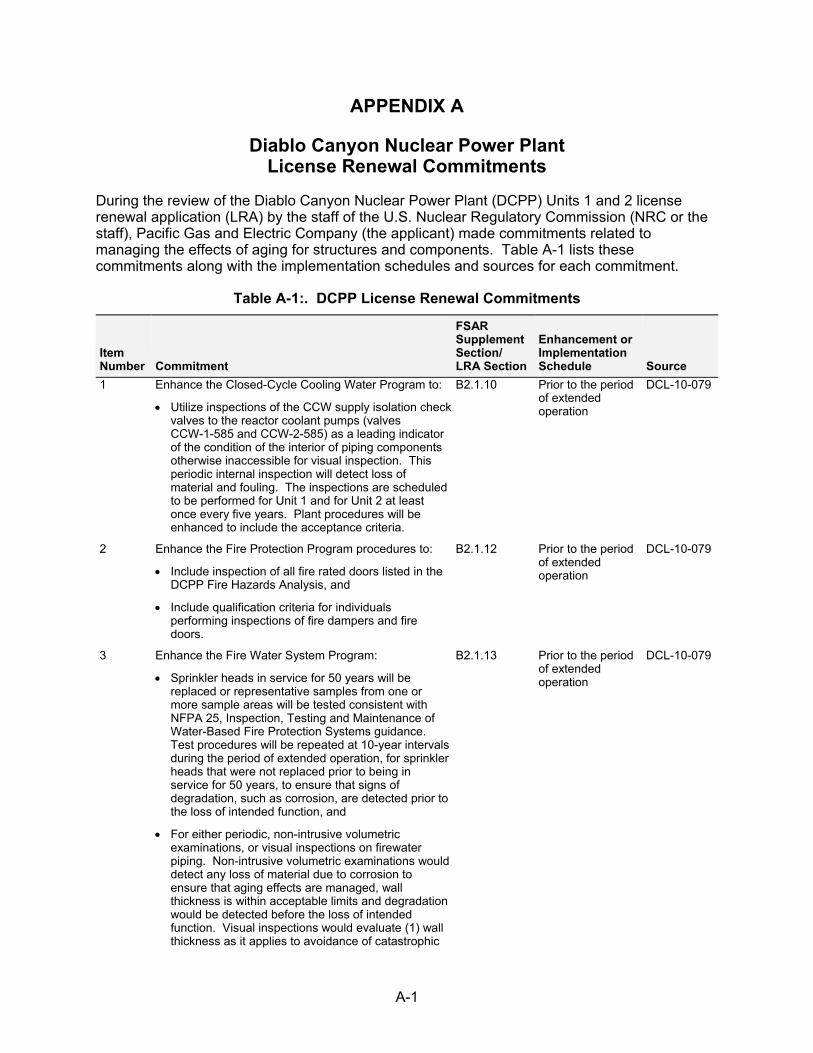
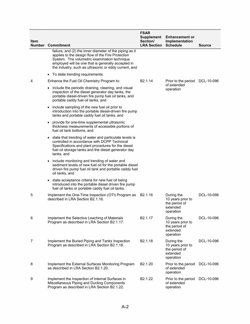
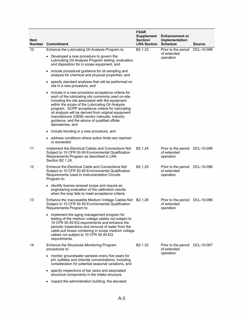
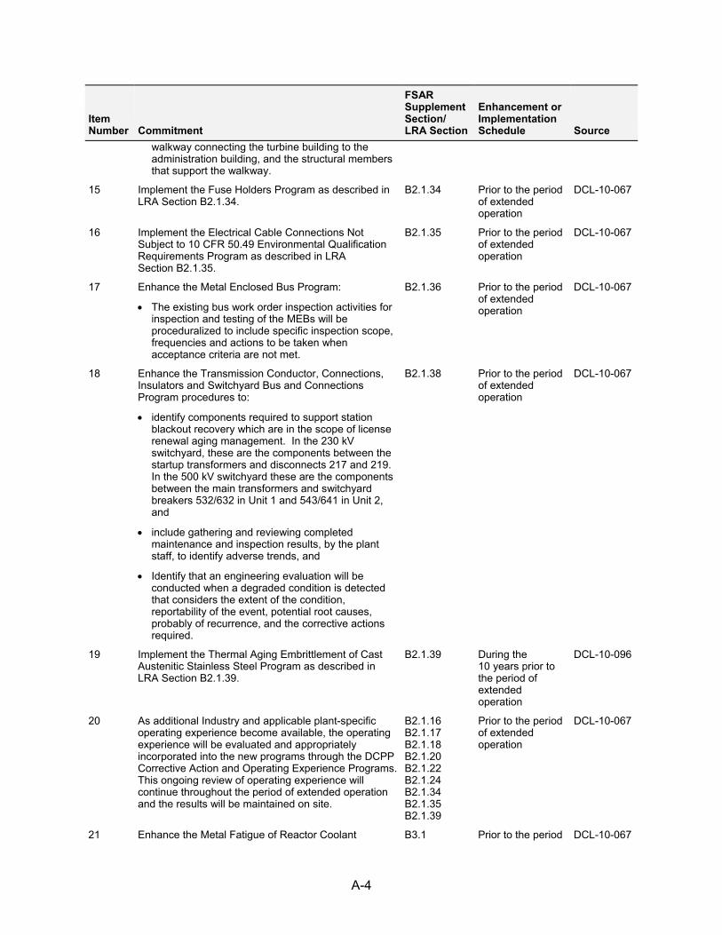
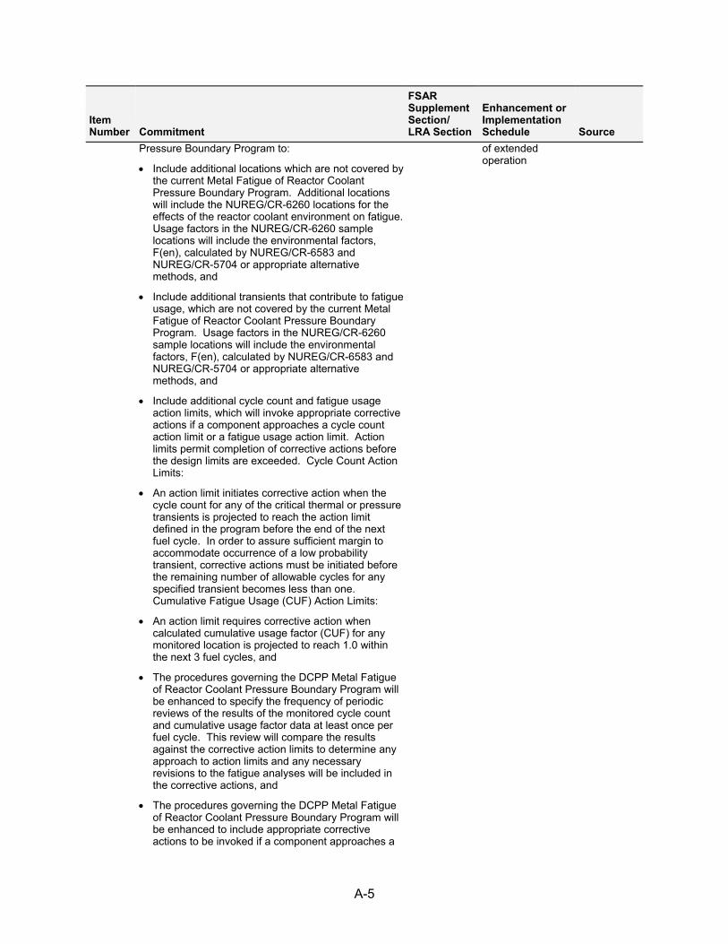
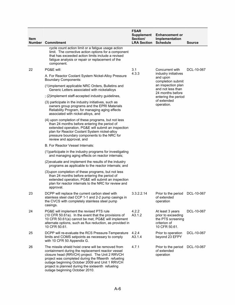
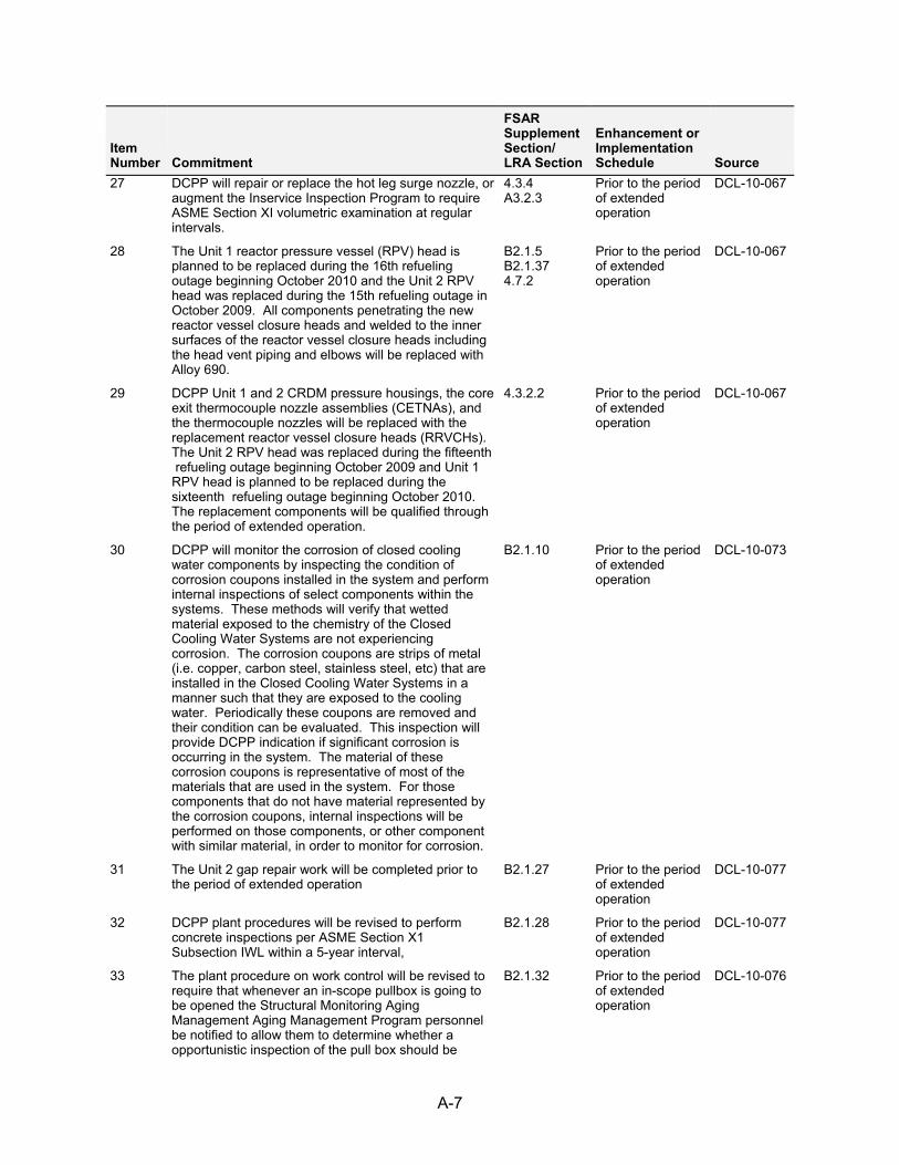
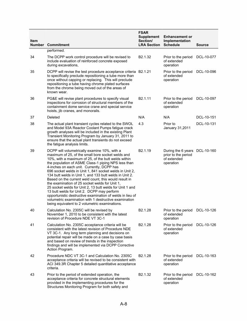
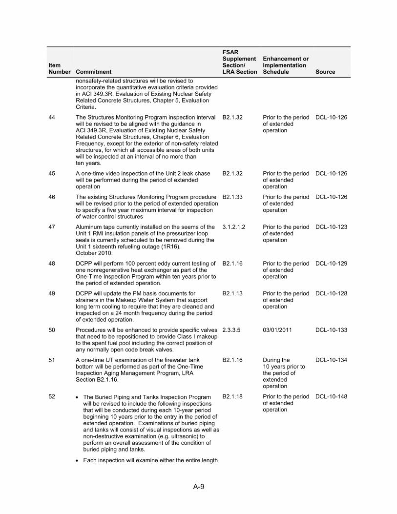
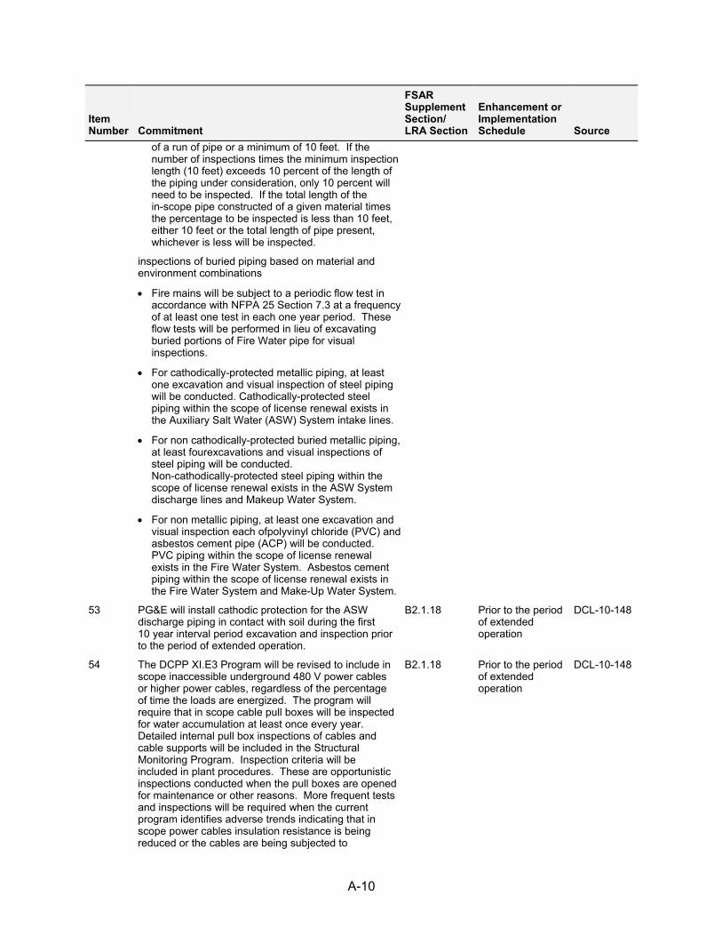
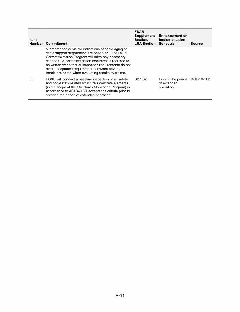
Appendix A DIABLO CANYON NUCLEAR POWER PLANT LICENSE RENEWAL COMMITMENTS ........................................................................................................... A-1
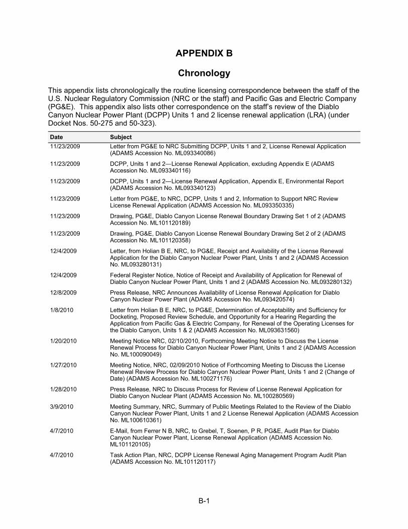
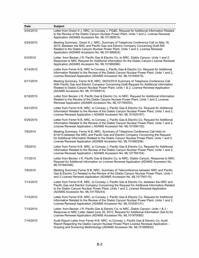
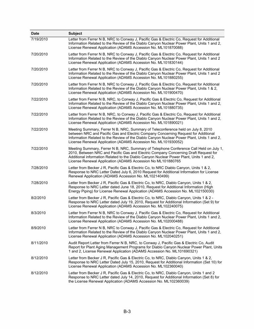
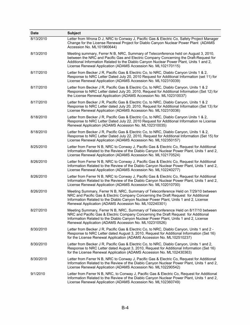
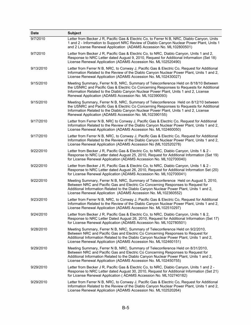
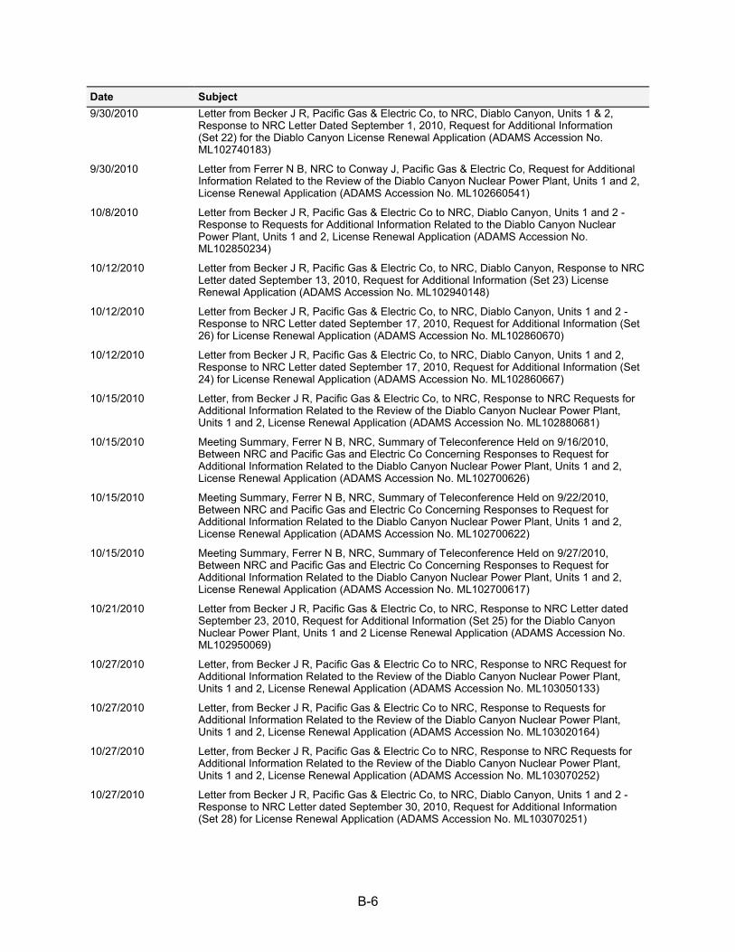
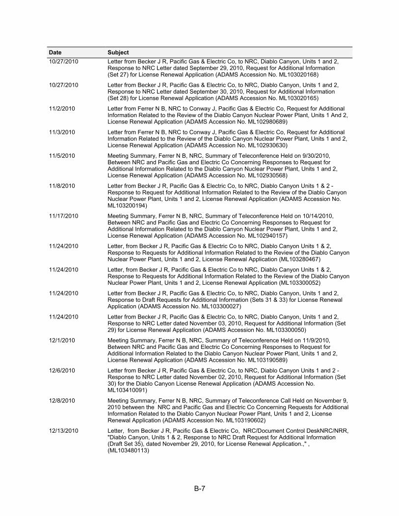
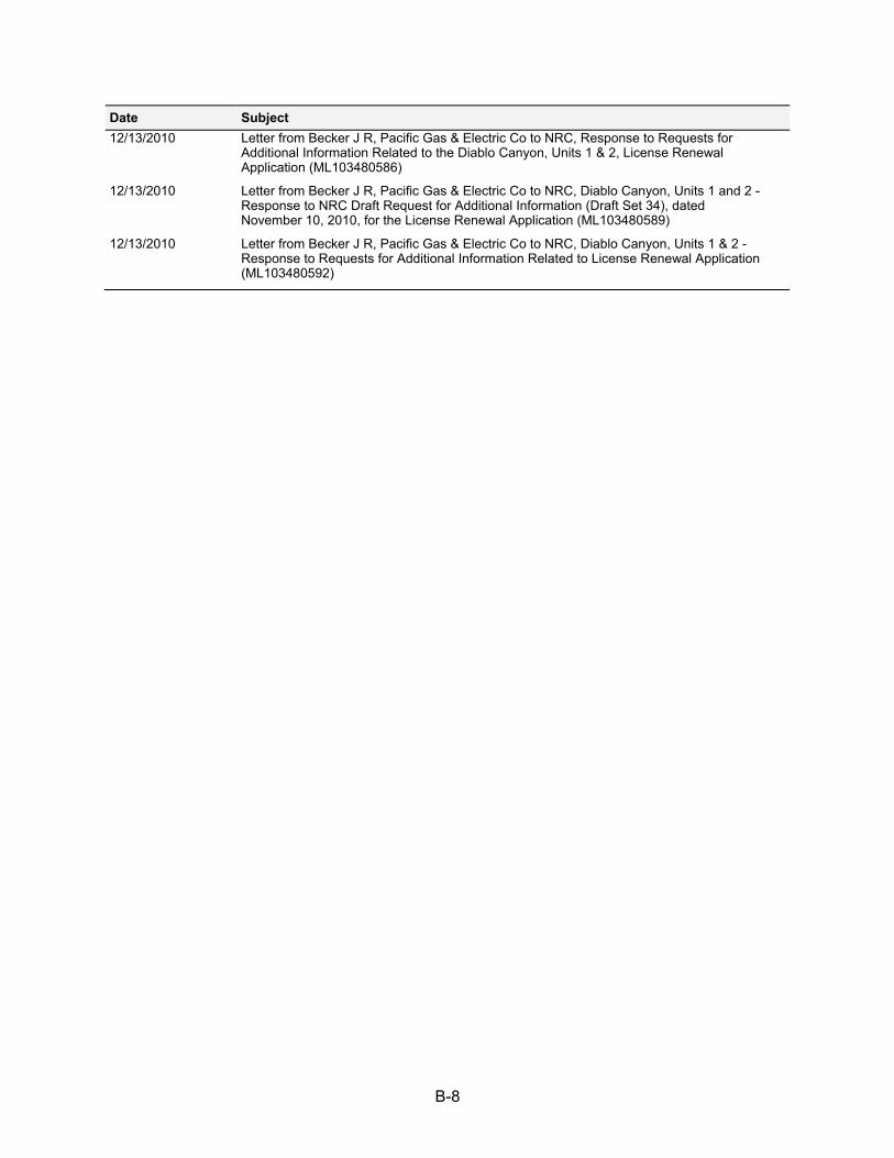
Appendix B CHRONOLOGY ................................................................................................... B-1
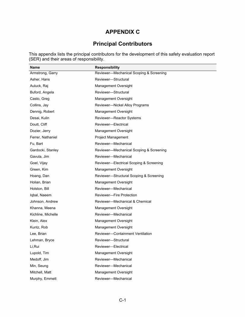
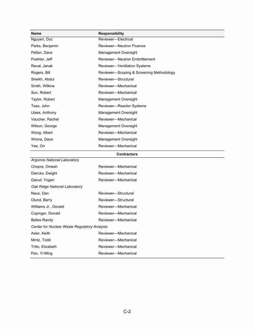
Appendix C PRINCIPAL CONTRIBUTORS ............................................................................ C-1
Appendix D REFERENCES .................................................................................................... D-1
xiii
LIST OF TABLES
Table 1.4-1 Current Interim Staff Guidance ............................................................................. 1-6
Table 3.0-1 Aging Management Programs .............................................................................. 3-7
Table 3.1-1 Staff Evaluation for Reactor Vessel, Reactor Vessel Internals and Reactor Coolant System Components in the GALL Report .................................................................. 3-176
Table 3.2-1 Staff Evaluation for Engineered Safety Features Systems Components in the GALL Report .............................................................................................................. 3-224
Table 3.3-1 Staff Evaluation for Auxiliary System Components in the GALL Report ........... 3-248
Table 3.4-1 Staff Evaluation for Steam and Power Conversion Systems Components in the GALL Report .............................................................................................................. 3-329
Table 3.5-1 Staff Evaluation for Structures and Component Supports Components in the GALL Report ........................................................................................................................ 3-359
Table 3.6-1 Staff Evaluation for Electrical and Instrumentation and Controls in the GALL Report ........................................................................................................................ 3-394

xiv
xv
ABBREVIATIONS
ACI American Concrete Institute ACP asbestos cement pipe ACRS Advisory Committee on Reactor Safeguards AERM aging effect requiring management AISE Association of Iron and Steel Engineers AMP aging management program AMR aging management review AMSAC ATWS mitigation system actuation circuitry ANSI American National Standards Institute APCSB auxiliary and power conversion systems branch ART adjusted reference temperature ASCE American Society of Civil Engineers ASM American Society for Metals ASME American Society of Mechanical Engineers ASTM American Society for Testing and Materials ASW auxiliary salt water ATS Applied Technology Services ATWS anticipated transient without scram BIT boron injection tank BTP Branch Technical Position BWR boiling water reactor CAP Corrective Action Program CASS cast austentic stainless steel CBF cycle based fatigue CCW component cooling water CE civil engineering CEA control element assembly CEOG Combustion Engineering Owner’s Group CETNA core exit thermocouple nozzle assembly CFCS containment fan cooler system CFCU containment fan cooling units CFR Code of Federal Regulations CISI containment inservice inspection CLB current licensing basis CO2 carbon dioxide COMS Cold Overpressure Mitigation System CRD control rod drive CRDM control rod drive mechanism
xvi
CRGT control rod guide tube CSS containment spray system CST condensate storage tank Cu copper CUF cumulative usage factors CVCS chemical and volume control system CWC circulating water conduits DBA design basis accident DBE design basis event DE design basis earthquake DCPP Diablo Canyon Power Plant DCWC discharge circulating water conduits DDE double design basis earthquake DE design engineering DECW diesel engine jacket cooling water EAF Environmentally-assisted fatigue ECCS emergency core cooling system ECT eddy current testing EFPY effective full power years EOCI Electric Overhead Crane Institute EOL end of life EOLE end of license extended EPA Environmental Protection Agency EPRI Electric Power Research Institute EQ environmental qualification ES engineering services ESF engineered safety feature F(en) environmental factor FERC Federal Energy Regulatory Commission FHB fuel handling building FIV flow-induced vibration FRN Federal Register Notice FSAR final safety analysis report FW feedwater FWSTT fire water storage and transfer tank GALL Generic Aging Lessons Learned GEIS Generic Environmental Impact Statement GL generic letter
xvii
GSI general safety issue HELB high-energy line break HEPA high-efficiency particulate air HVAC heating, ventilation, and air conditioning I&C instrumentation and controls IASCC Irradiation-assisted stress corrosion cracking IEEE Institute of Electrical and Electronics Engineers IGSCC intergranular stress corrosion cracking ILRT integrated leak rate test IN Information Notice IPA integrated plant assessment ISG interim staff guidance ISI inservice inspection ISO phase isolated phase kV kilovolt LBB leak-before-break LCO limiting conditions for operation LLRT local leak rate tests LOCA loss-of-coolant accident LRA license renewal application LRAAI license renewal applicant action item LTOP low temperature over pressurization protection LTR long term rate LTW long-term weight MEB metal enclosed bus MeV mega electron-volt MIC microbiologically influenced corrosion MRP Materials Reliability Program MSLB main steam line break MWt megawatt NaOH sodium hydroxide NDE nondestructive examination NEI Nuclear Energy Institute NFPA National Fire Protection Association Ni nickel NPS nominal pipe size
xviii
NRC U.S. Nuclear Regulatory Commission NS nuclear services NSSS nuclear steam supply system OBE operational basis earthquake OEM original equipment manufacturer OOS out of specification P&ID piping and instrumentation diagram PEP plant engineering procedure PG&E Pacific Gas & Electric PM preventative maintenance PORV power operated relief valves PRT pressurizer relief tank P-T pressure-temperature PTLR pressure-temperature limits report PTS pressurized thermal shock PVC polyvinyl chloride PWR pressurized water reactor PWSCC primary water stress corrosion cracking QA quality assurance RAI request for additional information RCCA rod cluster control assembly RCP reactor coolant pump RCPB reactor coolant pressure boundary RCS reactor coolant system RG Regulatory Guide RHR residual heat removal RI-ISI risk-informed inservice inspection RO refueling outage RPE responsible professional engineer RPV reactor pressure vessel RRVCH replacement reactor vessel closure head RTD resistance temperature detector RV reactor vessel RVI reactor vessel internals RVID reactor vessel integrity database RWST refueling water storage tank SAS spray additive system
xix
SBO station blackout SC structure and component SCC stress corrosion cracking SER safety evaluation report SF safety factor SFP spent fuel pool SG steam generator SGRP Steam Generator Replacement Project SI safety injection SISI seismically induced system interaction SOC statement of consideration SOV solenoid operating valve SRP-LR Standard Review Plan for Review of License Renewal SRRF stress range reduction factor SSC system, structure, or component SSE safe shutdown earthquake STR short term rate STW short-term weight TLAA time-limited aging analysis TS Technical Specification UFSAR updated final safety analysis report USAR updated safety analysis report USE upper shelf energy UT ultrasonic testing WCAP Westinghouse Commercial Atomic Power WOG Westinghouse Owners Group

xx
1-1
SECTION 1
1.0 INTRODUCTION AND GENERAL DISCUSSION
1.1 Introduction
This document is a safety evaluation report (SER) on the license renewal application (LRA) for Diablo Canyon Nuclear Power Plant (DCPP) Units 1 and 2, as filed by Pacific Gas and Electric Company (PG&E or the applicant). By letter dated November 23, 2009, PG&E submitted its application to the U.S. Nuclear Regulatory Commission (NRC) for renewal of the DCPP Units 1 and 2 operating licenses for an additional 20 years. The NRC staff (the staff) prepared this report to summarize the results of its safety review of the LRA for compliance with Title 10, Part 54, “Requirements for Renewal of Operating Licenses for Nuclear Power Plants,” of the Code of Federal Regulations (10 CFR Part 54). The NRC project manager for the license renewal review is Nathaniel Ferrer. Mr. Ferrer may be contacted by telephone at 301-415-1045, or by electronic mail at [email protected]. Alternatively, written correspondence may be sent to the following address:
Division of License Renewal US Nuclear Regulatory Commission Washington, D.C. 20555-0001 Attention: Nathaniel Ferrer, Mail Stop O11-F1
In its November 23, 2009, submission letter, the applicant requested renewal of the operating licenses issued under Section 104b (Operating License No. DPR-80 and DPR-82) of the Atomic Energy Act of 1954, as amended, for DCPP for a period of 20 years beyond the current expirations at midnight on November 2, 2024, for Unit 1, and at midnight on August 26, 2025, for Unit 2. DCPP is located approximately 12 miles west southwest of San Luis Obispo, CA. The NRC issued the construction permits on April 23, 1968, for Unit 1 and on December 9, 1970, for Unit 2. The NRC issued the operating licenses on November 2, 1984, for Unit 1 and on August 26, 1985, for Unit 2. DCPP employs a pressurized water reactor design with a dry ambient containment. Westinghouse Electric Corporation supplied the nuclear steam supply system. PG&E designed and constructed the balance of the plant with assistance from Bechtel. The licensed power output of each unit is 3,411 megawatt thermal with a gross electrical output of approximately 1,120 megawatt electric. The final safety analysis report (FSAR) contains details of the plant and the site.
The license renewal process consists of two concurrent reviews, a technical review of safety issues and an environmental review. The NRC regulations in 10 CFR Part 54 and 10 CFR Part 51, “Environmental Protection Regulations for Domestic Licensing and Related Regulatory Functions,” respectively, set forth requirements for these reviews. The safety review for the DCPP license renewal is based on the applicant’s LRA and on its responses to the staff’s requests for additional information (RAIs). The applicant supplemented the LRA and provided clarifications through its responses to the staff’s RAIs in audits, meetings, and docketed correspondence. Unless otherwise noted, the staff reviewed and considered information submitted through December 13, 2010. The staff reviewed information received after that date depending on the stage of the safety review and the volume and complexity of the information. The public may view the LRA and all pertinent information and materials, including the FSAR, at the NRC Public Document Room, located on the first floor of One White Flint North, 11555 Rockville Pike, Rockville, MD 20852-2738 (301-415-4737/800-397-4209). The LRA may also be viewed at the San Luis Obispo Public Library, 995 Palm Street, San Luis Obispo, CA 93401,
1-2
and at the Paso Robles Public Library, 1000 Spring Street, Paso Robles, CA 93446. In addition, the public may find the LRA, as well as materials related to the license renewal review, on the NRC Web site at http://www.nrc.gov.
This SER summarizes the results of the staff’s safety review of the LRA and describes the technical details considered in evaluating the safety aspects of the units' proposed operation for an additional 20 years beyond the term of the current operating licenses. The staff reviewed the LRA in accordance with NRC regulations and the guidance in NUREG-1800, Revision 1, “Standard Review Plan for Review of License Renewal Applications for Nuclear Power Plants” (SRP-LR), dated September 2005.
SER Sections 2 through 4 address the staff’s evaluation of license renewal issues considered during the review of the application. SER Section 5 is reserved for the report of the Advisory Committee on Reactor Safeguards (ACRS). The conclusions of this SER are in Section 6.
SER Appendix A is a table showing the applicant’s commitments for renewal of the operating licenses. SER Appendix B is a chronology of the principal correspondence between the staff and the applicant regarding the LRA review. SER Appendix C is a list of principal contributors to the SER and Appendix D is a bibliography of the references in support of the staff’s review.
In accordance with 10 CFR Part 51, the staff will prepare a draft, plant-specific supplement to NUREG-1437, “Generic Environmental Impact Statement for License Renewal of Nuclear Plants (GEIS).” This supplement will discuss the environmental considerations for license renewal for DCPP. The staff is scheduled to issue the draft, plant-specific GEIS Supplement in February 2011. The final, plant-specific GEIS Supplement is scheduled to be issued in October 2011.
1.2 License Renewal Background
Pursuant to the Atomic Energy Act of 1954, as amended, and NRC regulations, operating licenses for commercial power reactors are issued for 40 years and can be renewed for up to 20 additional years. The original 40-year license term was selected based on economic and antitrust considerations rather than on technical limitations; however, some individual plant and equipment designs may have been engineered for an expected 40-year service life.
In 1982, the staff anticipated interest in license renewal and held a workshop on nuclear power plant aging. This workshop led the NRC to establish a comprehensive program plan for nuclear plant aging research. From the results of that research, a technical review group concluded that many aging phenomena are readily manageable and pose no technical issues precluding life extension for nuclear power plants. In 1986, the staff published a request for comment on a policy statement that would address major policy, technical, and procedural issues related to license renewal for nuclear power plants.
In 1991, the staff published 10 CFR Part 54, the License Renewal Rule (Volume 56, page 64943, of the Federal Register (56 FR 64943), dated December 13, 1991). The staff participated in an industry-sponsored demonstration program to apply 10 CFR Part 54 to a pilot plant and to gain the experience necessary to develop implementation guidance. To establish a scope of review for license renewal, 10 CFR Part 54 defined age-related degradation unique to license renewal. However, during the demonstration program, the staff found that adverse aging effects on plant systems and components are managed during the period of initial license and that the scope of the review did not allow sufficient credit for management programs, particularly the implementation of 10 CFR 50.65, “Requirements for Monitoring the Effectiveness of Maintenance at Nuclear Power Plants,” which regulates management of
1-3
plant-aging phenomena. As a result of this finding, the staff amended 10 CFR Part 54 in 1995. As published May 8, 1995, in 60 FR 22461, amended 10 CFR Part 54 establishes a regulatory process that is simpler, more stable, and more predictable than the previous 10 CFR Part 54. In particular, as amended, 10 CFR Part 54 focuses on the management of adverse aging effects rather than on the identification of age-related degradation unique to license renewal. The staff made these rule changes to ensure that important systems, structures, and components (SSCs) will continue to perform their intended functions during the period of extended operation. In addition, the amended 10 CFR Part 54 clarifies and simplifies the integrated plant assessment process to be consistent with the revised focus on passive, long-lived structures and components (SCs).
Concurrent with these initiatives, the staff pursued a separate rulemaking effort (61 FR 28467, June 5, 1996) and amended 10 CFR Part 51 to focus the scope of the review of environmental impacts of license renewal in order to fulfill NRC responsibilities under the National Environmental Policy Act of 1969.
1.2.1 Safety Review
License renewal requirements for power reactors are based on two key principles:
(1) The regulatory process is adequate to ensure that the licensing bases of all currently operating plants maintain an acceptable level of safety with the possible exceptions of the detrimental aging effects on the functions of certain SSCs, as well as a few other safety-related issues, during the period of extended operation.
(2) The plant-specific licensing basis must be maintained during the renewal term in the same manner and to the same extent as during the original licensing term.
In implementing these two principles, 10 CFR 54.4, “Scope,” defines the scope of license renewal as including those SSCs that (1) are safety-related, (2) whose failure could affect safety-related functions, or (3) are relied on to demonstrate compliance with the NRC’s regulations for fire protection, environmental qualification (EQ), pressurized thermal shock (PTS), anticipated transient without scram (ATWS), and station blackout (SBO).
Pursuant to 10 CFR 54.21(a), a license renewal applicant must review all SSCs within the scope of 10 CFR Part 54 to identify SCs subject to an aging management review (AMR). Those SCs subject to an AMR perform an intended function without moving parts or without change in configuration or properties and are not subject to replacement based on a qualified life or specified time period. Pursuant to 10 CFR 54.21(a), a license renewal applicant must demonstrate that the aging effects will be managed such that the intended function(s) of those SCs will be maintained consistent with the current licensing basis (CLB) for the period of extended operation. However, active equipment is considered to be adequately monitored and maintained by existing programs. In other words, detrimental aging effects that may affect active equipment can be readily identified and corrected through routine surveillance, performance monitoring, and maintenance. Surveillance and maintenance programs for active equipment, as well as other maintenance aspects of plant design and licensing basis, are required throughout the period of extended operation.
Pursuant to 10 CFR 54.21(d), the LRA is required to include an FSAR supplement with a summary description of the applicant’s programs and activities for managing aging effects and an evaluation of time-limited aging analyses (TLAAs) for the period of extended operation.
License renewal also requires TLAA identification and updating. During the plant design phase, certain assumptions about the length of time the plant can operate are incorporated into design
1-4
calculations for several plant SSCs. In accordance with 10 CFR 54.21(c)(1), the applicant must either show that these calculations will remain valid for the period of extended operation, project the analyses to the end of the period of extended operation, or demonstrate that the aging effects on these SSCs will be adequately managed for the period of extended operation.
In 2005, the NRC revised Regulatory Guide (RG) 1.188, “Standard Format and Content for Applications to Renew Nuclear Power Plant Operating Licenses.” This RG endorses Nuclear Energy Institute (NEI) 95-10, Revision 6, “Industry Guideline for Implementing the Requirements of 10 CFR Part 54 - The License Renewal Rule,” issued in June 2005. NEI 95-10 details an acceptable method of implementing 10 CFR Part 54. The staff also used the SRP-LR to review the LRA.
In the LRA, the applicant used the process defined in NUREG-1801, Revision 1, “Generic Aging Lessons Learned (GALL) Report,” dated September 2005. The GALL Report summarizes staff-approved aging management programs (AMPs) for many SCs subject to an AMR. If an applicant commits to implementing these staff-approved AMPs, the time, effort, and resources for LRA review can be greatly reduced, improving the efficiency and effectiveness of the license renewal review process. The GALL Report summarizes the aging management evaluations, programs, and activities credited for managing aging for most of the SCs used throughout the industry. The report is also a quick reference for both applicants and staff reviewers to AMPs and activities that can manage aging adequately during the period of extended operation.
1.2.2 Environmental Review
Part 51 of 10 CFR contains regulations on environmental protection. In December 1996, the staff revised the environmental protection regulations to facilitate the environmental review for license renewal. The staff prepared the GEIS to document its evaluation of possible environmental impacts associated with nuclear power plant license renewals. For certain types of environmental impacts, the GEIS contains generic findings that apply to all nuclear power plants and are codified in Appendix B, “Environmental Effect of Renewing the Operating License of a Nuclear Power Plant,” to Subpart A, “National Environmental Policy Act - Regulations Implementing Section 102(2),” of 10 CFR Part 51. Pursuant to 10 CFR 51.53(c)(3)(i), a license renewal applicant may incorporate these generic findings in its environmental report. In accordance with 10 CFR 51.53(c)(3)(ii), an environmental report also must include analyses of environmental impacts that must be evaluated on a plant-specific basis (i.e., Category 2 issues).
In accordance with the National Environmental Policy Act of 1969 and 10 CFR Part 51, the staff reviewed the plant-specific environmental impacts of license renewal, including whether there was new and significant information not considered in the GEIS. As part of its scoping process, the staff held a public meeting on March 3, 2010, in San Luis Obispo, CA, to identify plant-specific environmental issues. The staff will prepare a draft, plant-specific supplement to the GEIS, which will document the results of the environmental review and make a preliminary recommendation as to the license renewal action. The staff will hold another public meeting to discuss the draft, plant-specific supplement to the GEIS.
1.3 Principal Review Matters
Part 54 of 10 CFR describes the requirements for renewal of operating licenses for nuclear power plants. The staff’s technical review of the LRA was in accordance with NRC guidance and 10 CFR Part 54 requirements. Section 54.29, “Standards for Issuance of a Renewed License,” of 10 CFR sets forth the license renewal standards. This SER describes the results of the staff’s safety review.
1-5
Pursuant to 10 CFR 54.19(a), the NRC requires a license renewal applicant to submit general information, which the applicant provided in LRA Section 1. The staff reviewed LRA Section 1 and finds that the applicant has submitted the required information.
Pursuant to 10 CFR 54.19(b), the NRC requires that the LRA include “conforming changes to the standard indemnity agreement, 10 CFR 140.92, Appendix B, to account for the expiration term of the proposed renewed license.” On this issue, the applicant stated the following in the LRA:
Indemnity Agreement No. B-75 states in Article VII that the agreement shall terminate at the time of expiration of that license specified in Item 3 of the attachment. Amendment No. 7 to Indemnity Agreement No. B-75 was issued as part of the Unit 1 full power license DPR-80 on November 2, 1984. Amendment No. 8 to Indemnity Agreement No. B-75 was issued as part of the Unit 2 full power license DPR-82 on April 25, 1985. Neither of these amendments had an expiration date specified in Item 3. Therefore no conforming changes to the indemnity agreement are deemed necessary as part of this application. Should the license numbers be changed by the NRC upon issuance of the renewed license, PG&E requests that NRC amend the indemnity agreement to include conforming changes to Item 3 of the attachment and other affected sections of the agreement.
The staff intends to maintain the original license numbers upon issuance of the renewed licenses, if approved. Therefore, conforming changes to the indemnity agreement need not be made, and the 10 CFR 54.19(b) requirements have been met.
Pursuant to 10 CFR 54.21, “Contents of Application - Technical Information,” the NRC requires that the LRA contain: (a) an integrated plant assessment, (b) a description of any CLB changes during the staff’s review of the LRA, (c) an evaluation of TLAAs, and (d) an FSAR supplement. LRA Sections 3 and 4 and Appendix B address the license renewal requirements of 10 CFR 54.21(a), (b), and (c). LRA Appendix A satisfies the license renewal requirements of 10 CFR 54.21(d).
Pursuant to 10 CFR 54.21(b), the NRC requires that, each year following submission of the LRA and at least three months before the scheduled completion of the staff’s review, the applicant submit an LRA amendment identifying any CLB changes to the facility that affect the contents of the LRA, including the FSAR supplement. By letter dated December 29, 2010, the applicant submitted an LRA update which summarizes the CLB changes that have occurred during the staff’s review of the LRA. This submission satisfies 10 CFR 54.21(b) requirements and is still under staff review.
Pursuant to 10 CFR 54.22, “Contents of Application - Technical Specifications,” the NRC requires that the LRA include changes or additions to the technical specifications (TS) that are necessary to manage aging effects during the period of extended operation. The applicant did not use Appendix D, thus indicating that no changes to the DCPP TS are required to support the LRA. This adequately addresses the 10 CFR 54.22 requirement.
The staff evaluated the technical information required by 10 CFR 54.21 and 10 CFR 54.22 in accordance with NRC regulations and SRP-LR guidance. SER Sections 2 through 4 document the staff’s evaluation of the LRA technical information.
As required by 10 CFR 54.25, “Report of the Advisory Committee on Reactor Safeguards,” the ACRS will issue a report documenting its evaluation of the staff’s LRA review and SER. SER
1-6
Section 5 is reserved for the ACRS report when it is issued. SER Section 6 documents the findings required by 10 CFR 54.29.
1.4 Interim Staff Guidance
License renewal is a living program. The staff, industry, and other interested stakeholders gain experience and develop lessons learned with each renewed license. The lessons learned address the staff’s performance goals of maintaining safety, improving effectiveness and efficiency, reducing regulatory burden, and increasing public confidence. Interim staff guidance (ISG) is documented for use by the staff, industry, and other interested stakeholders until incorporated into such license renewal guidance documents as the SRP-LR and GALL Report.
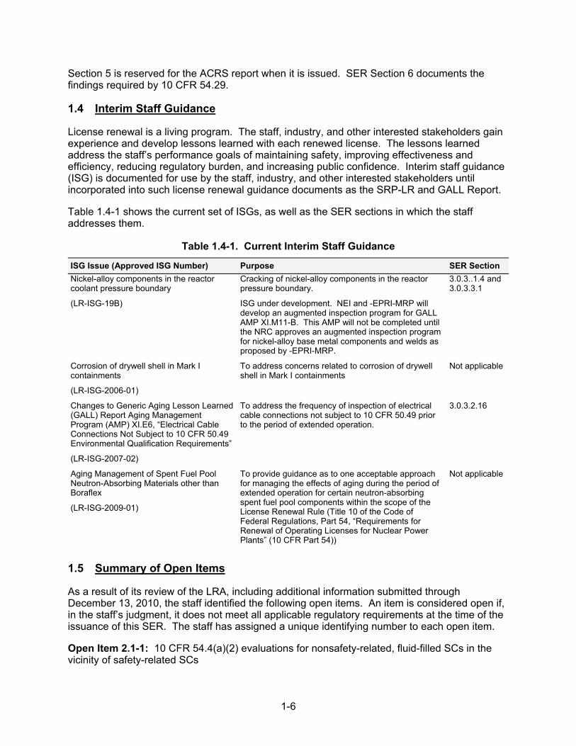
Table 1.4-1 shows the current set of ISGs, as well as the SER sections in which the staff addresses them.
Table 1.4-1. Current Interim Staff Guidance
ISG Issue (Approved ISG Number) Purpose SER Section
Nickel-alloy components in the reactor coolant pressure boundary
(LR-ISG-19B)
Cracking of nickel-alloy components in the reactor pressure boundary.
ISG under development. NEI and -EPRI-MRP will develop an augmented inspection program for GALL AMP XI.M11-B. This AMP will not be completed until the NRC approves an augmented inspection program for nickel-alloy base metal components and welds as proposed by -EPRI-MRP.
3.0.3..1.4 and 3.0.3.3.1
Corrosion of drywell shell in Mark I containments
(LR-ISG-2006-01)
To address concerns related to corrosion of drywell shell in Mark I containments
Not applicable
Changes to Generic Aging Lesson Learned (GALL) Report Aging Management Program (AMP) XI.E6, “Electrical Cable Connections Not Subject to 10 CFR 50.49 Environmental Qualification Requirements”
(LR-ISG-2007-02)
To address the frequency of inspection of electrical cable connections not subject to 10 CFR 50.49 prior to the period of extended operation.
3.0.3.2.16
Aging Management of Spent Fuel Pool Neutron-Absorbing Materials other than Boraflex
(LR-ISG-2009-01)
To provide guidance as to one acceptable approach for managing the effects of aging during the period of extended operation for certain neutron-absorbing spent fuel pool components within the scope of the License Renewal Rule (Title 10 of the Code of Federal Regulations, Part 54, “Requirements for Renewal of Operating Licenses for Nuclear Power Plants” (10 CFR Part 54))
Not applicable
1.5 Summary of Open Items
As a result of its review of the LRA, including additional information submitted through December 13, 2010, the staff identified the following open items. An item is considered open if, in the staff’s judgment, it does not meet all applicable regulatory requirements at the time of the issuance of this SER. The staff has assigned a unique identifying number to each open item.
Open Item 2.1-1: 10 CFR 54.4(a)(2) evaluations for nonsafety-related, fluid-filled SCs in the vicinity of safety-related SCs
1-7
During its review of how the applicant evaluated nonsafety-related, fluid-filled SCs in the vicinity of safety-related SCs, the staff determined that additional information was necessary in several areas. The staff reviewed the applicant's responses and determined that applicant had not satisfactorily resolved the staff's general concern that if certain nonsafety-related, fluid-filled SCs whose failure could prevent satisfactory accomplishment of any of the functions of safety-related SCs (within the scope of license renewal) then they are required to be included within the scope of license renewal. The resolution of this issue is tracked as Open Item 2.1-1. See SER Sections 2.1.4.1.2, 2.3, 2.3.3.7.
Open Item 2.3-1: 10 CFR 54.4(a)(2) evaluations for nonsafety-related fluid-filled SCs directly attached to safety-related SCs
The staff noted that on several license renewal boundary drawings, specifically in the compressed air system, the applicant shows nonsafety-related piping directly attached to safety-related piping, which was not included within the scope of license renewal. In a letter dated May 24, 2010, the staff issued an RAI requesting that applicant justify why it excluded the nonsafety-related piping attached to safety-related solenoid valves (SOVs), in the compressed air system. In its responses, the applicant stated that it excluded the nonsafety-related piping from scope of license renewal based on the guidance in NEI 95-10, Section 5.2.3.1 of Appendix F. The staff finds the applicant’s supplemental response unacceptable because the applicant did not provide justification for why NEI 95-10, Section 5.2.3.1 of Appendix F is applicable to the SOVs. The resolution of this issue is tracked as Open Item 2.3-1. See SER Section 2.3.
Open Item 2.3.3.14-1: Endpoint establishment for the diesel air start unloader line
The staff noted that, without an appropriate endpoint established between the safety-related (air start lines from the diesel generator air start receiver) and nonsafety-related SCs (air compressor) interface, the pressure boundary function would be compromised for the diesel generator system. By letter dated May 24, 2010, the staff issued an RAI, requesting that the applicant clarify its methodology used to determine an endpoint of safety-related piping where positive isolation does not exist. In its responses, the applicant stated that the tubing associated with the unloader line as nonsafety-related, quarter-inch diameter, stainless steel tubing from the isolation valve to the compressor, and that the tubing does not perform the intended function of pressure boundary. The applicant stated that the nonsafety-related portion of the tubing is credited with the intended function of “structural support.” Based on its review, the staff finds the applicant’s response unacceptable because the the unloader lines are part of the pressure boundary, and the applicant has not identified the compressor as an appropriate endpoint for the pressure boundary of the unloader line. The resolution of this issue is tracked as Open Item 2.3.3.14-1. See SER Section 2.3.3.14.
Open Item 3.0.3.2.12-1: Flux Thimble Tube Inspection Program
RAI B2.1.21-1: The staff noted that the Flux Thimble Tube Inspection Program does not include any uncertainty allowances in the through wall depth acceptance criterion. The staff noted that this is not consistent with the recommendation to include appropriate allowances for instrument measurement and wear scar geometry uncertainties, as documented in NRC Bulletin 88-09 or in the “monitoring and trending” program element of GALL AMP XI.M37. By letter dated December 20, 2010, the staff issued an RAI, requesting that the applicant justify not including an appropriate NDE measurement and wear scar geometry uncertainties in the wear projection basis or accounting for them in the acceptance criterion. This resolution of this issue is tracked as part of Open Item 3.0.3.1.12-1. See SER Section 3.0.3.2.12.
1-8
RAI B2.1.21-2: By letter dated July 14, 2010, the staff asked the applicant to provide a basis for why it considered the "incremental wear" and "cumulative wear" projection methods for the Flux Thimble Tube Inspection Program capable of conservatively projecting the amount of wear in a thimble tube to the next scheduled thimble tube inspection outage. The staff also asked the applicant to give its basis for adding each of the additional corrective actions that were discussed in the “operating experience” program element and explain what the corrective actions were intended to prevent and what they would accomplish if carried out.
In its response, the applicant provided an apparent cause analysis of the degradation that had occurred in the Unit 2 L13 thimble tube from the time it was replaced during Unit 2, tenth refueling outage, to when the tube had leaked in 2006. It also gave a detailed response on the basis for the additional corrective actions taken in response to the Unit 2 L13 thimble tube leakage in 2006. However, the applicant’s responses did not resolve the staff’s concerns regarding if the program is capable of detecting wear in a thimble tube before the occurrence of a through wall leak.
By letter dated December 20, 2010, the staff issued a follow-up RAI, requesting that the applicant identify the quality activities that are taken to find and confirm the apparent cause of age related degradation that is detected in a flux thimble tube. The staff also asked the applicant to give its basis for concluding that the Flux Thimble Tube Inspection Program will be capable of detecting degradation in a flux thimble before the occurrence of a through wall failure. The resolution of this issue is tracked as part of Open Item 3.0.3.1.12-1. See SER Section 3.0.3.1.12.
Open Item 3.0.3.2.8-1: Buried Piping and Tanks Inspection Program
By letter dated August 3, 2010, the staff issued an RAI requesting that the applicant explain how it will incorporate the recent industry operating experience into its Buried Piping and Tanks Inspection Program.
In it responses dated August 30, 2010, and November 24, 2010, the applicant stated that given recent industry operating experience, the Buried Piping and Tanks Inspection Program will include a risk assessment that will include factors such as consequences of leakage, conditions affecting risk for corrosion, hazards posed by the fluid contained in the piping, soil resistivity, drainage, presence of cathodic protection and the type of coating. The applicant also provided details on how much of the buried, in-scope piping is cathodically protected, and details of its inspections methods. Based on its review, the staff found the response to RAI B2.1.18-2 incomplete for the following reasons:
The LRA states that there are buried copper valves in the make-up water system. The applicant’s response did not address how the aging effect for these valves will be managed.
The applicant did not state how many feet of steel pipe are in the make-up water valve pit.
The resolution of this issue is tracked as Open Item 3.0.3.2.8-1. See SER Section 3.0.3.2.8.
Open Item 4.1-1: Time-limited aging analyses identification
RAI 4.1-6: The staff determined that the information and basis in LRA Section 4.3.2.6 does not give the staff a sufficient basis for verifying that there do not need to be any TLAAs identified for the reactor coolant pressure boundary valves. By letter dated December 20, 2010, the staff issued an RA, requesting further clarification on why the LRA did not identify any cumulative
1-9
usage factor (CUF) or similar analyses as TLAAs for ASME Code Class 1 valves in the reactor coolant pressure boundary. The resolution of this issue is tracked as part of Open Item 4.1-1. See SER Section 4.3.2.6.2.
RAI 4.1-7: The staff noted that the applicant’s conclusion that the CUF calculation for the baffle and former bolts no longer serve a safety basis and do not need to be identified as a TLAA for the plant is not valid. By letter dated December 20, 2010, the staff issued an RAI, requesting that the applicant clarify why the CUF calculation for the baffle and former bolts does not meet 10 CFR 54.3(a)(4) and to explain why the CUF analysis for the baffle and former bolts does not need to be identified as a TLAA. The resolution of this issue is tracked as part of Open Item 4.1-1. See SER Section 4.3.3.2.3
Open Item 4.3-1: Metal Fatigue
RAI 4.3-1: The staff determined that use of cycle counting against the transients in the leak before break (LBB) methodology is not accounted for under an applicable enhancement of the program in LRA Commitment No. 21 or defined in the applicant’s CLB. By letter dated December 20, 2010, the staff issued an RAI 4.3-1, requesting that the applicant give its basis for proposing use of cycle counting against the LBB. The resolution of this issue is tracked as part of Open Item 4.3-1. See SER Section 4.3.1.2.1.
RAI 4.3-4: In its response to RAI 4.3-4, the applicant clarified that the “auxiliary spray during cooldown” transient is within the scope of the Metal Fatigue of Reactor Coolant Pressure Boundary Program. The staff noted that the applicant’s response only stated that the “auxiliary spray during cooldown” transient was within the scope of the Metal Fatigue of Reactor Coolant Pressure Boundary Program but did not justify why the transient was omitted from the scope of LRA Table 4.3-2. The staff was not able to determine if the “auxiliary spray during cooldown” transient would be projected to exceed the number of occurrences assumed for the transient prior to reaching the end of the period of extended operation. By letter dated December 20, 2010, the staff issued a follow-up RAI 4.3-4, requesting that the applicant provide the LRA Table 4.3.2 values for the “auxiliary spray during cooldown” transient. The resolution of this issue is tracked as part of Open Item 4.3-1. SEE SER Section 4.3.1.2.2.
RAI 4.3-5: The staff noted that the applicant's response to RAI 4.3-5 provided its bases and the data that were used for derivation to the long term rate (LTR) and long term weight (LTW) and the short term rate (STR) and short term weight (STW) used in the 60 year projections for the DCPP design transients. However, the staff still could not determine how the 2.15 safety factor (SF) was factored into the cycle data and the LTR, LTW, STR, and STW values for these transients. In a letter dated December 20, 2010, the staff issued a follow-up RAI, requesting that the applicant give additional clarification on how the 2.15 SF related to the cycle data and the LTR, LTW, STR, and STW values for these charging system transients. The resolution of this issue is tracked as part of Open Item 4.3-1. See SER Section 4.3.1.2.2.
RAI 4.3-10: The staff noted that Revision 19 of FSAR Table 5.2-4 still notes the unit loading and unloading at 5 percent per minute transients and the steady state fluctuations transient as applicable transients within the requirements of Technical Specification (TS) 5.5.5. By letter dated December 20, 2010, the staff issued an RAI, requesting that the applicant explain why the monitoring of the unit loading and unloading transients and the steady state fluctuation transient could be omitted without accounting for it in FSAR Section 5.2 or FSAR Table 5.2-4 and the applicant’s cycle counting procedure. The resolution of this issue is tracked as part of Open Item 4.3-1. See SER Section 4.3.3.2.1.
1-10
RAI 4.3-12: The staff noted that the applicant’s response to RAI 4.3-12 identifies that cumulative fatigue damage is an applicable aging effect for ASME Code Class 2 or 3 or ANSI B31.1 piping, piping components and pipe fittings in the remaining engineered safety features systems. The staff also noted that the applicant did not include the applicable AMR item for the containment spray system. By letter dated December 20, 2010, the staff issued a follow-up RAI, requesting that the applicant justify why it did not include AMR items on cumulative fatigue damage for piping, piping components, and piping elements in the containment spray system that were designed to either ASME Section III requirements for Class 2 or 3 components or to ANSI B31.1 requirements. The resolution of this issue is tracked as part of Open Item 4.3-1. See SER Section 3.2.2.2.1.
RAI 4.3-13: The staff noted that the applicant dispositioned the CUF values for the 2009 replacement Unit 2 upper reactor vessel (RV) closure head components, and its control rod driver mechanism (CRDM) and core exit thermocouple nozzle assemblies (CETNA) nozzle components, in accordance with 10 CFR 54.21(c)(1)(i) without providing any supporting CUF values to demonstrate continued validity for the period of extended operation. The staff also noted that the applicant dispositioned the Unit 1 upper RV closure head components, and its CRDM and CETNA nozzle components, in accordance with 10 CFR 54.21(c)(1)(i). By letter dated December 20, 2010, the staff issued an RAI, requesting that the applicant provide the CUF values of record for the Units 1 and 2 upper RV closure heads and CETNA and CRDM penetration nozzle components. Alternatively, the staff requested justification for dispositioning the TLAA in accordance with 10 CFR 54.21(c)(1)(i) without submitting the CUF values for the components. The resolution of this issue is part of Open Item 4.3-1. See SER Section 4.3.2.2.2.
RAI 4.3-14: The staff noted that the applicant stated that it will use its Metal Fatigue of Reactor Coolant Pressure Boundary Program to disposition the CUF analyses of record for the upper core plate and lower core plate components, in accordance with 10 CFR 54.21(c)(1)(iii). The staff also noted that the applicant identified the transients that were analyzed in the existing 50year design basis calculations for the upper core plate and lower core plate components along with the existing design basis limits on assumed cycles for the transients. However, based on the applicant’s CUF evaluations for the upper core plates and lower core plates, the staff was not able to determine if bounding meant that the number of assumed transient cycles were greater or less than the existing design basis limits. By letter dated December 20, 2010, the staff issued an RAI, requesting clarification on whether the Metal Fatigue of Reactor Coolant Pressure Boundary Program would be counting the transients for the upper core plates and lower core plates based on a comparison of the design transient limits in FSAR Table 5.2-4 or those in the updated CUF analyses. The resolution of this issue is tracked as part of Open Item 4.3-1. See SER Section 4.3.2.10.2.
RAI 4.3-15: The staff noted that, in LRA Tables 4.3-3 and 4.3-6, the applicant reported that the RV and pressurizer components had CUFs that were greater than those used for the pressurizer or RV locations used in the applicant's environmentally-assisted fatigue (EAF) analysis evaluation. The staff noted that the applicant did not include these component locations for EAF calculations. By letter dated December 20, 2010, the staff issued an RAI, requesting that the applicant clarify if it had considered additional reactor coolant pressure boundary (RCPB) components for inclusion in the EAF analyses. The resolution of this issue is tracked as part of Open Item 4.3-1. See SER Section 3.0.3.2.19.
The staff noted that, although the applicant's assumption to use an assumed dissolved oxygen concentration of less than 0.05 parts per million (ppm) yields a conservative environmental factor (Fen) results for stainless steel components, lowering the dissolved oxygen concentration in the RCS coolant has the opposite effect on carbon steel and low alloy steel components. By
1-11
letter dated December 20, 2010, the staff issued an RAI, requesting that the applicant justify the use of an assumed dissolved oxygen concentration of less than 0.05 ppm and a Fen of 2.46, for the low alloy steel RCPB components, was considered to be sufficiently conservative. The resolution of this issue is part of Open Item 4.3-1. See SER Section 4.3.4.2.
RAI 4.3-16: The staff noted that the number of occurrences assumed for the double design basis earthquake and Hosgri earthquake seismic events in LRA Section 4.3.6 were the same as those assumed for the design basis. However, in FSAR Table 5.2-4, the design basis assumes 20 occurrences of the design basis earthquake (DE) event under the seismic design basis, whereas LRA Section 4.3.6 reports the design basis assumes 5 occurrence of the DE event. By letter dated December 20, 2010, the staff issued an RAI, requesting that the applicant explain the difference in the two values that were reported assumed occurrences of the DE seismic event. The resolution of this issue is tracked as part of Open Item 4.3-1. See SER Section 4.3.6.2.
Open Item 4.7.5-1: Flaw Growth Evaluation for RHR piping Weld WIC-95
The staff noted that the non-destructive examination results provided by the applicant cannot discriminate between a near-surface and surface-connected flaw in weld WIC-95; therefore, the flaw cannot be characterized as embedded in the pipe wall thickness. In addition, based on the proximity rule of the ASME Code, Section IWA-3300, the applicant should assume the flaw is connected to the inside surface. The staff noted that the applicant’s flaw evaluation as shown in the response to RAI 4.7.5-2, dated December 6, 2010, did not consider the flaw growth due to stress corrosion cracking. This resolution of this issue is tracked as Open Item 4.7.5-1. See SER Section 4.7.5.
1.6 Summary of Confirmatory Items
As a result of its review of the LRA, including additional information submitted through December 13, 2010, the staff identified the following confirmatory item. An item is considered confirmatory if the staff and the applicant have reached a satisfactory resolution but the applicant has not yet formally submitted the resolution. The staff has assigned a unique identifying number to each confirmatory item.
Confirmatory Item 3.0.3.2.14-1: Inaccessible Medium Voltage Cables Not Subject to 10 CFR 50.49 Environmental Qualification Requirements Program
The staff noted that the applicant failed to provide adequate explanation for the basis to maintain power cables testing at least once every 10 years. The staff also noted that the applicant will not perform inspection of run boxes after events which can cause elevated level of water; however, the applicant did not provide sufficient details of the pull box configuration to justify why these inspections would not be necessary. During a conference call held on December 8, 2010, the applicant stated that it will change the cable testing frequency to at least once every 6 years and will confirm to the staff that all of the in-scope pull boxes have a sump pump installed or have a drainage path to a sump pump. The staff finds this acceptable upon confirmation of cable testing frequency revision from at least once every 10 years to at least once every 6 years and description of pull box drainage path configurations. The resolution of issue is tracked as Confirmatory Item 3.0.3.2.14-1. See SER Section 3.0.3.2.14.
Confirmatory Item 3.0.3.2.18-1: Structures Monitoring Program
In its response to an RAI, the applicant committed to performing a one-time video inspection of the Unit 2 leak chase during the period of extended operation. However, the staff was not clear
1-12
when, during the period of extended operation, the applicant would perform the inspection. During a teleconference held on January 4, 2010, the applicant stated that it will perform the inspection within 1 year prior to entering the period of extended operation, and will supplement its response to clarify this issue. This issue is pending receipt of the applicant's submittal of additional information, and is identified as Confirmatory Item 3.0.3.2.18-1. See SER Section 3.0.3.2.18-1
1.7 Summary of Proposed License Conditions
Following the staff’s review of the LRA, including subsequent information and clarifications from the applicant, the staff identified 3 proposed license conditions.
The first license condition requires the applicant to include the FSAR supplement required by 10 CFR 54.21(d) in the next FSAR update, required by 10 CFR 50.71(e), following the issuance of the renewed licenses.
The second license condition requires future activities described in the FSAR supplement to be completed prior to the period of extended operation.
The third license condition requires that all capsules in the reactor vessel that are removed and tested meet the requirements of American Society for Testing and Materials (ASTM) E 185-82 to the extent practicable for the configuration of the specimens in the capsule. Any changes to the capsule withdrawal schedule, including spare capsules, must be approved by the staff prior to implementation. All capsules placed in storage must be maintained for future insertion. Any changes to storage requirements must be approved by the staff, as required by 10 CFR Part 50, Appendix H.
2-1
SECTION 2
2.0 STRUCTURES AND COMPONENTS SUBJECT TO AGING MANAGEMENT REVIEW
2.1 Scoping and Screening Methodology
2.1.1 Introduction
Title 10, Section 54.21, “Contents of Application—Technical Information,” of the Code of Federal Regulations (10 CFR 54.21) requires an integrated plant assessment (IPA) for each license renewal application (LRA). The IPA must list and identify all of the structures, systems, and components (SSCs) within the scope of license renewal in accordance with 10 CFR 54.4 and all structures and components (SCs) subject to an aging management review (AMR) in accordance with 10 CFR 54.21.
LRA Section 2.1, “Scoping and Screening Methodology,” describes the scoping and screening methodology used to identify the SSCs at the Diablo Canyon Power Plant (DCPP) Unit 1 and Unit 2 within the scope of license renewal and the SCs subject to an AMR. The staff reviewed the scoping and screening methodology of Pacific Gas and Electric Company (PG&E or the applicant) to determine whether it meets the scoping requirements of 10 CFR 54.4(a) and the screening requirements of 10 CFR 54.21.
In developing the scoping and screening methodology for the LRA, the applicant stated that it considered the requirements of 10 CFR Part 54, “Requirements for Renewal of Operating Licenses for Nuclear Power Plants,” (the Rule), statements of consideration for the Rule, and the guidance of Nuclear Energy Institute (NEI) 95-10, Revision 6, “Industry Guideline for Implementing the Requirements of 10 CFR Part 54 - The License Renewal Rule,” dated June 2005 (NEI 95-10).
2.1.2 Summary of Technical Information in the Application
LRA Sections 2 and 3 state the technical information required by 10 CFR 54.4 and 54.21(a). LRA Section 2.1 describes the process for identifying SSCs meeting the license renewal scoping criteria of 10 CFR 54.4(a) and the process for identifying SCs subject to an AMR, as required by 10 CFR 54.21(a)(1). The applicant provided the results of the process for identifying such SCs in the following LRA sections:
Section 2.2, “Plant Level Scoping Results”
Section 2.3, “Scoping and Screening Results: Mechanical Systems”
Section 2.4, “Scoping and Screening Results: Structures”
Section 2.5, “Scoping and Screening Results: Electrical and Instrumentation and Control (I&C) Systems”
LRA Section 3, “Aging Management Review Results,” states the applicant’s aging management results in the following LRA sections:
Section 3.1, “Aging Management of Reactor Vessel, Internals, and Reactor Coolant System”
2-2
Section 3.2, “Aging Management of Engineered Safety Features Systems”
Section 3.3, “Aging Management of Auxiliary Systems”
Section 3.4, “Aging Management of Steam and Power Conversion Systems”
Section 3.5, “Aging Management of Containments, Structures, and Component Supports”
Section 3.6, “Aging Management of Electrical and Instrumentation and Controls”
LRA Section 4, “Time-Limited Aging Analyses,” states the applicant’s evaluation of time-limited aging analyses.
2.1.3 Scoping and Screening Program Review
The staff evaluated the LRA scoping and screening methodology in accordance with the guidance in Section 2.1, “Scoping and Screening Methodology,” of NUREG-1800, Revision 1, “Standard Review Plan for Review of License Renewal Applications for Nuclear Power Plants” (SRP-LR), dated September 2005. The following regulations form the basis for the acceptance criteria for the scoping and screening methodology review:
10 CFR 54.4(a) as to identification of plant SSCs within the scope of the Rule
10 CFR 54.4(b) as to identification of the intended functions of plant systems and structures within the scope of the Rule
10 CFR 54.21(a)(1) and 10 CFR 54.21(a)(2) as to the methods used by the applicant to identify plant SCs subject to an AMR
As part of the review of the applicant’s scoping and screening methodology, the staff reviewed the activities described in the following sections of the LRA using the guidance contained in the SRP-LR:
Section 2.1—to ensure that the applicant described a process for identifying SSCs within the scope of license renewal in accordance with 10 CFR 54.4(a)
Section 2.2—to ensure that the applicant described a process for identifying SCs subject to an AMR in accordance with 10 CFR 54.21(a)(1) and 10 CFR 54.21(a)(2)
In addition, the staff carried out a scoping and screening methodology audit at DCPP, located in Avila Beach, CA, near San Luis Obispo, CA, during the week of March 15–18, 2010. The audit focused on ensuring that the applicant had developed and implemented adequate guidance to carry out the scoping and screening of SSCs in accordance with the methodologies described in the LRA and the requirements of the Rule. The staff reviewed implementation of the technical position papers describing the applicant’s scoping and screening methodology. The staff had detailed discussions with the applicant on the implementation and control of the license renewal program and reviewed the administrative control documentation used by the applicant during the scoping and screening process, the quality practices used by the applicant to develop the LRA, and the training and qualification of the LRA development team.
The staff evaluated the quality attributes of the applicant’s aging management program (AMP) activities described in Appendix A, “Final Safety Analysis Report Supplement,” and Appendix B, “Aging Management Programs,” of the LRA. On a sampling basis, the staff performed a system review of the emergency diesel generators, auxiliary feedwater, and the main steam systems, including a review of the scoping and screening results reports and supporting design documentation used to develop the reports. The purpose of the staff’s review was to ensure
2-3
that the applicant had appropriately implemented the methodology outlined in the administrative controls and to verify that the results are consistent with the current licensing basis (CLB) documentation.
2.1.3.1 Implementation Procedures and Documentation Sources for Scoping and Screening
The staff reviewed the applicant's scoping and screening implementing procedures, as documented in the scoping and screening methodology audit trip report, dated July 16, 2010, to verify that the process used to identify SCs subject to an AMR is consistent with the SRP-LR. Additionally, the staff reviewed the scope of CLB documentation sources and the process used by the applicant to ensure that applicant’s commitments, as documented in the CLB, were appropriately considered and that the applicant adequately implemented its procedural guidance during the scoping and screening process.
2.1.3.1.1 Summary of Technical Information in the Application
In LRA Section 2.1, the applicant addressed the following information sources for the license renewal scoping and screening process:
CLB documents engineering drawings technical position papers plant equipment database Q-List
2.1.3.1.2 Staff Evaluation
Scoping and Screening Implementation Procedures. The staff reviewed the applicant’s scoping and screening methodology implementing procedures, including license renewal guidelines, documents, and reports, as documented in the audit trip report, to ensure the guidance is consistent with the requirements of the Rule, the SRP-LR, and NEI 95-10. The staff finds that the overall process used to implement the 10 CFR Part 54 requirements described in the implementing procedures and AMRs is consistent with the Rule, the SRP-LR, and industry guidance.
The applicant’s implementing procedures contain guidance for determining plant SSCs within the scope of the Rule and for determining which SCs within the scope of license renewal are subject to an AMR. During the review of the implementing procedures, the staff focused on the consistency of the detailed procedural guidance with information in the LRA, including the implementation of NRC staff positions documented in the SRP-LR and the information in the applicant’s responses, dated June 18, 2010, to the staff’s requests for additional information (RAIs) dated May 24, 2010.
After reviewing the LRA and supporting documentation, the staff determined that the scoping and screening methodology implementing procedures are consistent with the methodology description provided in LRA Section 2.1. The applicant’s methodology is sufficiently detailed to provide concise guidance on the scoping and screening implementation process to be followed during the LRA activities.
Sources of Current Licensing Basis Information. The staff reviewed the scope and depth of the applicant's CLB review to verify that the methodology is sufficiently comprehensive to identify SSCs within the scope of license renewal as well as SCs requiring an AMR. Pursuant to
2-4
10 CFR 54.3(a), the CLB is the set of NRC requirements applicable to a specific plant and a licensee's written commitments for ensuring compliance with, and operation within, applicable NRC requirements and the plant-specific design bases that are docketed and in effect. The CLB includes applicable NRC regulations, orders, license conditions, exemptions, technical specifications, and design-basis information (documented in the most recent FSAR). The CLB also includes licensee commitments remaining in effect that were made in docketed licensing correspondence, such as licensee responses to NRC bulletins, generic letters, enforcement actions, and licensee commitments documented in NRC safety evaluations or licensee event reports.
During the audit, the staff reviewed pertinent CLB information sources used by the applicant including the FSAR supplement, and design basis information. In addition, the applicant’s license renewal process identified additional sources of plant information pertinent to the scoping and screening process, including the plant equipment database, position papers, analyses, license renewal boundary drawings, and reports. The staff confirmed that the applicant’s detailed license renewal program guidelines specified the use of the CLB source information in developing scoping evaluations.
The plant equipment database, CLB, Q-List, and plant drawings were the applicant’s primary repository for system identification and component safety classification information. During the audit, the staff reviewed the applicant’s administrative controls for the plant equipment database, design basis information, and other information sources used to verify system information. Plant administrative procedures describe these controls and govern their implementation. Based on a review of the administrative controls and a sample of the system classification information contained in the applicable DCPP documentation, the staff noted that the applicant has established adequate measures to control the integrity and reliability of DCPP system identification and safety classification data. Therefore, the staff determined that the information sources used by the applicant during the scoping and screening process provided a sufficiently controlled source of system and component data to support scoping and screening evaluations.
During the staff’s review of the applicant’s CLB evaluation process, the applicant explained the incorporation of updates to the CLB and the process used to ensure that they adequately incorporate those updates into the license renewal process. The staff determined that LRA Section 2.1 provided a description of the CLB and related documents used during the scoping and screening process that is consistent with the guidance contained in the SRP-LR.
In addition, the staff reviewed the implementing procedures and results reports used to support identification of SSCs that the applicant relied on to demonstrate compliance with the safety-related criteria, nonsafety-related criteria, and the regulated events criteria in accordance with 10 CFR 54.4(a). The applicant’s license renewal program guidelines provided a listing of documents used to support scoping and screening evaluations. The staff noted that these design documentation sources are useful for ensuring that the initial scope of SSCs, identified by the applicant, was consistent with the plant's CLB.
2.1.3.1.3 Conclusion
Based on its review of LRA Section 2.1, the detailed scoping and screening implementing procedures and the results from the scoping and screening audit, the staff concludes that the applicant's scoping and screening methodology considers CLB information in a manner consistent with the Rule, the SRP-LR, and NEI 95-10 guidance and, therefore, is acceptable.
2-5
2.1.3.2 Quality Controls Applied to License Renewal Application Development
2.1.3.2.1 Staff Evaluation
The staff reviewed the quality assurance controls used to ensure that the applicant adequately carried out scoping and screening methodologies described in the LRA. The applicant applied the following quality assurance processes during the LRA development:
The applicant developed written procedures, guidelines, and position papers to direct implementation of the scoping and screening methodology, control LRA development, and describe training requirements and documentation.
Contractor staff prepared and checked draft LRA-related documents, which were examined by the applicant’s team in a series of reviews—including reviews by the project engineer, senior reactor operator (a subject matter expert), independent technical reviewer—for owner acceptance.
Self-assessment teams, led by independent experts, examined the LRA in the period before application submittal. These assessments included evaluating contractor readiness for submittal and various portions of the LRA.
An industry peer group and plant review committee reviewed the draft LRA.
The applicant addressed and resolved the comments received through the review and assessment processes. The applicant applied configuration controls on the various draft reports and LRA versions.
The applicant used their corrective action processes to track and capture any identified issues for resolution.
The staff reviewed the applicant’s written procedures and documentation of assessment activities and determined that the applicant had developed adequate procedures to control the LRA development and assess the results of the activities.
2.1.3.2.2 Conclusion
Based on its review of pertinent LRA development guidance, discussion with the applicant’s license renewal staff, review of the applicant’s documentation of the activities performed to assess the quality of the LRA, the staff concludes that the applicant’s quality assurance activities provide assurance that LRA development activities were performed in accordance with the applicant’s license renewal program requirements.
2.1.3.3 Training
2.1.3.3.1 Staff Evaluation
The staff reviewed the applicant’s training process for consistent and appropriate guidelines and methodology for the scoping and screening activities.
The staff reviewed the applicant’s training process to ensure the applicant applied guidelines and methodology for the scoping and screening activities in a consistent and appropriate manner. As outlined in the implementing procedures, the applicant requires training for all personnel participating in the development of the LRA and uses only trained and qualified personnel to prepare the scoping and screening implementing procedures. The training included the following activities:
2-6
The applicant required training for the license renewal project personnel, which followed written guidance.
The applicant provided initial orientation training and overview of license renewal processes to all license renewal project personnel regardless of previous experience.
The required training included self-study activities with follow-up discussions with project leads. The applicant captured and documented the training of license renewal project personnel in indoctrination records.
The applicant provided mentoring for new license renewal project personnel by staff with previous license renewal experience.
The staff reviewed the applicant’s written procedures and, on a sampling basis, reviewed completed qualification, training records, and completed checklists for some of the applicant’s license renewal personnel. The staff determined that the applicant had developed and implemented adequate procedures to control the training of personnel performing LRA activities.
2.1.3.3.2 Conclusion
On the basis of discussions with the applicant’s license renewal project personnel responsible for the scoping and screening process and its review of selected documentation in support of the process, the staff concludes that the applicant’s personnel are adequately trained to implement the scoping and screening methodology described in the applicant’s implementing procedures and the LRA.
2.1.3.4 Conclusion of Scoping and Screening Program Review
On the basis of a review of information provided in LRA Section 2.1, a review of the applicant’s detailed scoping and screening implementing procedures, discussions with the applicant’s license renewal personnel, and the results from the scoping and screening methodology audit, the staff concludes that the applicant’s scoping and screening program is consistent with the SRP-LR and the requirements of 10 CFR Part 54 and, therefore, is acceptable.
2.1.4 Plant Systems, Structures, and Components Scoping Methodology
LRA Section 2.1 describes the applicant’s methodology used to scope SSCs in accordance with the requirements of 10 CFR 54.4(a). The LRA states that the scoping process categorized the entire plant in terms of major systems and structures with respect to license renewal. According to the LRA, major systems and structures were evaluated against criteria provided in 10 CFR 54.4 (a)(1), (2), and (3) to determine whether the system or structure should be considered within the scope of license renewal. The LRA states that that the scoping process identified the SSCs that are safety-related and perform or support an intended function for responding to a design basis event (DBE); are nonsafety-related but their failure could prevent accomplishment of a safety related function; or support a specific requirement for one of the five regulated events applicable to license renewal. LRA Section 2.1.1, “Introduction,” states that the scoping methodology used by DCPP is consistent with 10 CFR Part 54 and with the industry guidance contained in NEI 95-10.
2.1.4.1 Application of the Scoping Criteria in Title 10, Part 54.4(a)(1) of the Code of Federal Regulations
2.1.4.1.1 Summary of Technical Information in the Application
LRA Section 2.1.2.1, “Title 10 CFR 54.4(a)(1) – Safety-Related,” states the following:
2-7
10 CFR 54.4(a)(1) requires that plant SSCs within the scope of license renewal include safety-related SSCs which are those relied upon to remain functional during and following design-basis events (as defined in 10 CFR 50.49(b)(1)) to ensure the following functions:
(i) The integrity of the reactor coolant pressure boundary;
(ii) The capability to shutdown the reactor and maintain it in a safe shutdown condition; or,
(iii) The capability to prevent or mitigate the consequences of accidents which could result in potential offsite exposure comparable to those referred to in 50.34(a)(1), 50.67(b)(2), or 100.11, as applicable.
DCPP Design and Quality Group Classifications
Design and quality group classifications for SSCs are described in the FSAR, the Q-List or in design basis documents such as engineering drawings, evaluations, or calculations. The design and quality classifications for individual components are documented on engineering drawings and the Q-List, and are documented in the plant equipment database.
…The FSAR provides a description and definitions of the classifications for SSCs based on design class, seismic category, and quality assurance classifications.
DCPP specific definitions for design and quality classifications in the FSAR, Q List, and maintenance rule program are not inconsistent with the definition of safety-related provided in 10 CFR 54.4(a)(1). The following terms and classification designations are used in DCPP procedures, Q-List, and CLB documents.
Safety-Related - Those SSCs that are to remain functional during and after a design basis event to ensure reactor coolant pressure boundary integrity, capability to shutdown the reactor and maintain it in safe shutdown conditions, or capability to prevent or mitigate the consequences of accidents comparable to 10 CFR Part 100 guidelines.
Design Class I - Plant features important to safety, including plant features required to assure: (1) the integrity of the reactor coolant pressure boundary, (2) the capability to shut down the reactor and maintain it in a safe shutdown condition, or (3) the capability to prevent or mitigate the consequences of accidents which could result in potential offsite exposures comparable to the guideline exposures of 10 CFR Part 100. With respect to instrumentation, only those instruments designated as Design Class 1A, 1B, or 1C and Quality Group Q are considered safety-related.
QA [quality assurance] Class 'Q' - Equipment and structures to which the QA provisions of Appendix B to 10 CFR 50 apply for design, procurement, and construction. All SSCs designated as 'Q' are also Design Class I.
For the purposes of scoping and screening, all SSCs identified as Design Class I, safety-related, or QA Class 'Q' have been used to identify SSCs satisfying one or
2-8
more of the criteria of 10 CFR 54.4(a)(1) and included within the scope of license renewal.
FSAR Section 3.2.1 states that plant features important to safety are those necessary to ensure (1) the integrity of the reactor coolant pressure boundary, (2) the capability to shut down the reactor and maintain it in a safe shutdown condition, or (3) the capability to prevent or mitigate the consequences of accidents that could result in potential offsite exposures comparable to the guideline exposures of 10 CFR Part 100.
Design Basis Events
The FSAR and procedures governing safety-related and important to safety design classifications refer to design basis events (DBEs) while 10 CFR 54.4(a)(1) is more specific referring to design basis events as defined in 10 CFR 50.49(b)(1)…As part of the scoping methodology, a position paper was prepared to confirm that all applicable design basis events were considered. The FSAR identifies the DCPP DBEs.
…The FSAR review identified the set of DBEs and confirmed that the DCPP license renewal process had evaluated the associated SSCs consistent with the criteria of the Rule.
Exposure Guidelines
The exposure guidelines used for DCPP license renewal are the same as 10 CFR 54.4 with the exception of the guidelines cited for off-site exposures. In addition to the guidelines of 10 CFR Part 100, 10 CFR 54.4(a)(1)(iii) references the dose guidelines of 10 CFR 50.34(a)(1) and 10 CFR 50.67(b)(2). The guidelines of 10 CFR 50.34(a)(1) are applicable to facilities seeking a construction permit and are therefore not applicable to DCPP license renewal. The exposure guidelines of 10 CFR 50.67(b)(2) address the use of alternate source terms. Except for the fuel handling accident analysis, DCPP has not implemented the alternate source term guidelines of 10 CFR 50.67(b)(2). Therefore the guidelines of 10 CFR 50.67(b)(2) are applicable only by exception, through specific license amendments, under the DCPP CLB. A review of the systems and components that are credited in the fuel handling accident analysis was performed to ensure the applicable systems and components were included in the scope of license renewal. Therefore, use of the DCPP safety related design classification designators are consistent with 10 CFR 54.4(a)(1) scoping criteria.
2.1.4.1.2 Staff Evaluation
Pursuant to 10 CFR 54.4(a)(1), the applicant must consider safety-related SSCs relied upon to remain functional during and following a DBE to ensure the following functions:
the integrity of the reactor coolant pressure boundary
the ability to shut down the reactor and maintain it in a safe shutdown condition
the capability to prevent or mitigate the consequences of accidents that could result in potential offsite exposures comparable to those referred to in 10 CFR 50.34(a)(1), 10 CFR 50.67(b)(2), or 10 CFR 100.11.
2-9
With regard to identification of DBEs, SRP-LR Section 2.1.3, “Review Procedures,” states the following:
The set of DBEs as defined in the Rule is not limited to Chapter 15 (or equivalent) of the [Updated Final Safety Analysis Report] UFSAR. Examples of DBEs that may not be described in this chapter include external events, such as floods, storms, earthquakes, tornadoes, or hurricanes, and internal events, such as a high energy line break. Information regarding DBEs as defined in 10 CFR 50.49(b)(1) may be found in any chapter of the facility UFSAR, the Commission's regulations, NRC orders, exemptions, or license conditions within the CLB. These sources should also be reviewed to identify SSCs relied upon to remain functional during and following DBEs (as defined in 10 CFR 50.49(b)(1)) to ensure the functions described in 10 CFR 54.4(a)(1).
During the audit, the applicant stated that it evaluated the types of events listed in NEI 95-10 (i.e., anticipated operational occurrences, design basis accidents (DBAs), external events, and natural phenomena) that are applicable to DCPP. The staff reviewed the applicant’s basis documents, which described all design basis conditions in the CLB and addressed all events defined by 10 CFR 50.49(b)(1) and 10 CFR 54.4(a)(1). The DCPP FSAR and basis documents discussed events such as internal and external flooding, tornados, and missiles. The staff noted that the applicant’s evaluation of DBEs is consistent with the SRP-LR.
The applicant performed scoping of SSCs for the 10 CFR 54.4(a)(1) criterion in accordance with the license renewal implementing procedures that provide guidance for the preparation, review, verification, and approval of the scoping evaluations to ensure the adequacy of the results of the scoping process. The staff reviewed the implementing procedures governing the applicant’s evaluation of safety-related SSCs and sampled the applicant’s reports of the scoping results to ensure that the applicant applied the methodology in accordance with the implementing procedures. In addition, the staff discussed the methodology and results with the applicant's personnel who were responsible for these evaluations.
The staff reviewed the applicant’s evaluation of the Rule and CLB definitions pertaining to 10 CFR 54.4(a)(1) and determined that the DCPP CLB definition of safety-related and the applicable quality classifications, safety-related, Design Class I, and QA Class “Q” met the definition of safety-related specified in the Rule. The staff reviewed a sample of the license renewal scoping results for the auxiliary feedwater, emergency diesel generators, main steam systems, and the turbine building to provide additional assurance that the applicant adequately implemented their scoping methodology with respect to 10 CFR 54.4(a)(1). The staff verified that the applicant developed the scoping results for each of the sampled systems consistently with the methodology, identified the SSCs credited for performing intended functions, and adequately described the basis for the results as well as the intended functions. The staff also confirmed that the applicant identified, and used pertinent engineering and licensing information to identify, the SSCs required to be within the scope of license renewal in accordance with 10 CFR 54.4(a)(1) criteria.
The staff determined that additional information would be required to complete the review of the applicant’s scoping methodology. By letter dated May 24, 2010, the staff issued RAI 2.1-1, which states the following:
During the scoping and screening methodology audit, performed on site March 15-18, 2010, the staff determined that the applicant had certain components within the scope of license renewal, identified as safety-related in the component database, but that had been evaluated and determined to not
2-10
support a license renewal intended function corresponding to the requirements of 10 CFR 54.4(a)(1). The staff requests that the applicant provide a description of the process used to perform this evaluation.
The applicant responded to RAI 2.1-1 by letter dated June 18, 2010, which states the following:
As discussed in LRA Section 2.1.1.1, various documentation sources were used during the scoping and screening process for safety-related systems, structures, and components. The sources included the plant equipment database, approved engineering documents and the Q-List to identify safety-related components.
While conducting the scoping and screening process, inconsistencies between component classifications in the plant equipment database and the expected classifications were found based on comparison to adjacent components and/or approved engineering documents. Corrective action documents were created for inconsistencies to track the determination of the appropriate component classification in the plant equipment database. Pending resolution of the corrective action evaluation of the component classification, components classified as safety related in either the plant component database or engineering documents were included in the scope of license renewal per 10 CFR 54.4(a)(1) unless the equipment was determined to be abandoned. If the component was evaluated through the corrective action process and it was established that the component was not safety related and did not provide any other license renewal intended function then the component was screened as not within the scope of license renewal.
Abandoned equipment identified as safety-related in the plant equipment database was treated as nonsafety related where it had no safety-related intended function and was evaluated under 10 CFR 54.4(a)(2). Where the abandoned equipment performs a pressure boundary function, it is included within the scope of license renewal per 10 CFR 54.4(a)(1).
Therefore, a review of this issue concluded that use of this methodology did not preclude the identification of SSCs that should have been included within the scope of license renewal in accordance with 10 CFR 54.4(a). The review concluded that no additional scoping evaluations were required to be performed to address the 10 CFR 54.4(a) criteria.
In reviewing the applicant’s response, the staff finds that the applicant did not provide an appropriate evaluation of nonsafety-related SCs with the potential to adversely interact with SCs within the scope of license renewal under 10 CFR 54.4(a)(1) inside the turbine building. The staff identified the nonsafety-related SCs near the control room pressurization system (CRPS) as an example of where these SCs could potentially affect the safety-related CRPS in an adverse manner. By letter dated September 17, 2010, the staff issued RAI 2.1-1 (follow-up), asking the applicant to provide an evaluation of the nonsafety-related SCs in the vicinity of safety-related SCs in the turbine building and provide justification for excluding SCs, in accordance with the methodology as stated in the LRA Section 2.1.2.2, from the scope of license renewal.
In its response dated October 12, 2010, the applicant identified nonsafety-related, fluid-filled SCs in the diesel generator (DG) rooms, the component cooling water (CCW) rooms, the 125 VDC battery rooms, and the 4 kV switchgear room. The applicant provided the following
2-11
evaluations for the nonsafety-related, fluid-filled SCs near the safety-related SCs in these locations:
Nonsafety-related, fluid-filled SCs were evaluated near the instrument tubing for pressure transmitters that provide redundant first stage impulse pressure input from the high pressure turbine to the reactor trip circuit, and input to the main steam dump control circuitry and input to anticipated transient without scram (ATWS) mitigation system actuation circuitry (AMSAC). This instrument tubing is located in the turbine building from the transmitters located in the CCW heat exchanger rooms up to the high-pressure turbines. The applicant determined that the spray from the failure of nonsafety-related, fluid-filled SCs onto the tubing would not impact the AMSAC’s safety intended function, since the affected tubing would induce the AMSAC to initiate a reactor trip due to loss of pressure. Therefore, the applicant excluded the nonsafety-related, fluid-filled SCs near the instrument tubing from scope of license renewal.
Nonsafety-related, fluid-filled SCs were evaluated near the emergency diesel generator (EDG) exhaust lines that exit through the top of the EDG rooms in the turbine building. The applicant evaluated the nonsafety-related, fluid-filled SCs for any impact on the exhaust lines that could block the flow path from the EDGs. The applicant indicated in its response that the high energy SCs in the turbine building will be age managed, which includes those located near the exhaust lines to prevent the possibility of damage by pipe whip or jet impingement. The applicant determined that failure of other nonsafety-related, fluid-filled SCs onto the exhaust lines would not prevent the safety function of the EDGs. Therefore, these SCs are excluded from the scope of license renewal. The applicant also stated that the exhaust lines are subject to periodic external surfaces monitoring to ensure that effects of aging on external surfaces are managed.
Nonsafety-related, fluid-filled SCs were evaluated near the safety-related HVAC supply and exhaust ducts for the vital 480 V switchyard rooms. The HVAC supply and exhaust ducts provide a directed flow path for supply and exhaust ventilation air to and from the vital 480 V switchgear rooms. The applicant evaluated all the nonsafety-related, fluid-filled SCs for any impact on the HVAC ducts that could block the flow path. The applicant indicated in its response that the high energy SCs in the turbine building will be age managed, which includes those located near the HVAC ducts to prevent the possibility of damage by pipe whip or jet impingement. The applicant determined that the failure of the other nonsafety-related, fluid-filled SCs would not block the flow path sufficiently to have a significant impact on the safety function of the ducts. Therefore, these nonsafety-related SCs are excluded from scope of license renewal. The applicant also indicated that the HVAC ducts are subject to periodic external surfaces monitoring to ensure that the effects of aging on the external surfaces will be managed.
Nonsafety-related, fluid-filled SCs were evaluated near the CRPS system and components, which includes supply fans, valves, instrumentation and pipe duct. The applicant specifically identified and evaluated the fire water system piping, service water system piping, and a small head tank near the CRPS pipe duct. The applicant excluded these nonsafety-related SCs from the scope of license renewal due to the design of the CRPS pipe duct, which can operate in the environment in which it is located. The applicant referenced Section 5.2.3.2 of NEI 95-10, Rev. 6, Appendix F, as its basis for excluding the nonsafety-related SCs near the CRPS pipe duct. The applicant also stated that the CRPS pipe duct is designed to withstand the pressures of a high-energy line break event.
Based on its review, the staff finds part of the applicant’s supplemental response to RAI 2.1-1 acceptable. The applicant did identify additional nonsafety-related, fluid-filled SCs near safety-
2-12
related SCs in the turbine building. The staff finds the applicant’s justification for excluding nonsafety-related SCs near the instrument tubing for the pressure transmitters and EDG exhaust lines to be adequate since the failure of those fluid-filled SCs would not prevent the intended functions of the safety-related SCs. The staff also finds the applicant’s evaluation of the nonsafety-related, fluid-filled SCs near the CRPS pipe duct to be adequate. However, regarding the applicant’s evaluation of the nonsafety-related, fluid-filled SCs near the HVAC supply and exhaust ducts and the additional CRPS components, the staff finds the applicant’s response unacceptable. For the HVAC supply and exhaust ducts in the 480 V switchgear rooms, the applicant did not provide an adequate 10 CFR 54.4(a)(2) evaluation to specifically justify why the nonsafety-related, fluid-filled piping near the exhaust ducts would not impact (e.g., water intrusion through duct opening) the intended function of the ducts. Also regarding the CRPS, although the applicant evaluated the nonsafety-related, fluid-filled SCs near the CRPS pipe duct, the applicant did not provide a 10 CFR 54.4(a)(2) evaluation for the nonsafety-related, fluid-filled SCs near the CRPS supply fans, controls, and instrumentation. The resolution of this issue is tracked as Open Item 2.1-1.
2.1.4.1.3 Conclusion
On the basis of its review of systems (on a sampling basis), discussions with the applicant, and review of the applicant's scoping process the staff concludes, with the exception of Open Item 2.1-1, that the applicant's methodology for identifying systems and structures is consistent with the SRP-LR and 10 CFR 54.4(a)(1), and therefore, is acceptable.
2.1.4.2 Application of the Scoping Criteria in Title 10, Part 54.4(a)(2) of the Code of Federal Regulations
2.1.4.2.1 Summary of Technical Information in the Application
LRA Section 2.1.2.2, “Title 10 CFR 54.4(a)(2) - Non-Safety Related Affecting Safety-Related,” states the following:
10 CFR 54.4(a)(2) requires that plant SSCs within the scope of license renewal include all nonsafety-related SSCs whose failure could prevent satisfactory accomplishment of any of the functions identified for safety-related SSCs. The guidance provided in NEI 95-10, Appendix F was used to develop the methodology for scoping to the criterion of 10 CFR 54.4(a)(2).
The methodology includes identification of nonsafety-related SSCs that are connected to safety-related SSCs and nonsafety-related SSCs that could spatially interact with safety-related SSCs. Determination and identification of any other SSCs satisfying criterion 10 CFR 54.4(a)(2) was completed as described below based on review of applicable CLB documents, plant specific and industry operating experience, and by system and structure functional evaluations.
...
Functional Support for Safety-Related SSCs 10 CFR 54.4(a)(1) Functions
The FSAR and other CLB documents were reviewed for every plant system or structure, to determine whether the system or structure was credited with supporting satisfactory accomplishment of a safety-related function. Nonsafety-related systems or structures credited in CLB documents with
2-13
providing functional or structural support for the accomplishment of a safety-related function were classified as satisfying the criterion of 10 CFR 54.4(a)(2) and were included within the scope of license renewal.
The DCPP Operating Licenses include a condition to implement the Seismically Induced System Interaction (SISI) Program to ensure that SSCs required for safe shutdown of the plant as well as certain accident mitigating systems will not be impaired from performing their safety function as a result of seismically induced interactions when subjected to a seismic event of severity up to and including the postulated 7.5M Hosgri event. The SISI program identifies both safety-related and nonsafety-related SSCs that are required for safe shutdown of the plant as well and for mitigation of certain accidents. A review of the SISI Program documents was performed to ensure that all such components were included in the scope of license renewal.
Nonsafety-related SSCs directly connected to safety related SSCs
Nonsafety-related SSCs that are directly connected to a safety-related SSC were included within the scope of license renewal to ensure structural integrity of the safety-related SSC up to the first seismic anchor or equivalent anchor past the safety/nonsafety interface. In cases where seismic anchors were not available to serve as the license renewal boundary, the following methods as provided for in NEI 95-10, Appendix F, were utilized to establish the license renewal boundary:
A base-mounted component…
A flexible connection…
A free end of nonsafety-related piping, such as a drain pipe that ends at an open floor drain.
…
A point where buried piping exits the ground...
Nonsafety-related piping runs that are connected at both ends to safety-related piping include the entire run of nonsafety-related piping.
A smaller branch line where the moment of inertia ratio of the larger piping to the smaller piping is such that the smaller branch line does not impose loads on the larger piping and does not support the larger piping.
A combination of restraints or supports such that the nonsafety-related piping and associated structures and components attached to safety-related piping is included in scope up to a boundary point that encompasses two supports in each of three orthogonal directions.
A large piece of plant equipment (e.g., a heat exchanger) or a series of supports that have been evaluated as part of a plant-specific design analysis to ensure that forces and moments are restrained in three orthogonal directions.
Nonsafety-related SSCs with the potential for spatial interaction with safety related SSCs
Nonsafety-related SSCs which are not connected to safety-related piping and/or which are not required for structural integrity, but have a spatial relationship such
2-14
that their potential failure could adversely impact the performance of the intended function of a safety-related SSC, were included in the scope of license renewal per NEI 95-10, Appendix F. DCPP applied both the preventative and mitigative options for 10 CFR 54.4(a)(2) scoping.
The preventative option as implemented at DCPP is based on an approach for scoping of nonsafety-related SSCs having potential spatial interaction with safety-related SSCs. Potential spatial interaction is evaluated for any SSC in proximity to active or passive safety-related SSCs. The structures of concern for potential spatial interaction were identified based on the review of the CLB to determine which structures contained safety-related SSCs.
Nonsafety-related systems and components that contain fluid or steam, and are located inside structures that contain safety-related SSCs are included in scope for potential spatial interaction under criterion 10 CFR 54.4(a)(2).
High-energy lines located inside primary containment are included within the scope of license renewal. High-energy lines located outside primary containment are included within the scope of license renewal if their failure could adversely impact any safety-related SSCs.
...
DCPP applied the mitigative option for 10 CFR 54.4(a)(2) scoping of certain SSCs located in the turbine building. The mitigative option was applied to exclude certain SSCs from the 10 CFR 54.4(a)(2) scope where the only potential interaction with a safety-related SSC was fluid spray onto conduit containing safety-related electrical cables. These cables are protected by solid pipe conduit that is in scope as a structural component.
Supports for nonsafety-related SSCs are included in scope to prevent adverse interaction with safety-related SSCs.
2.1.4.2.2 Staff Evaluation
Pursuant to 10 CFR 54.4(a)(2), the applicant must consider all nonsafety-related SSCs whose failure could prevent the satisfactory accomplishment of safety-related functions for SSCs relied on to remain functional during and following a DBE to ensure the following:
the integrity of the reactor coolant pressure boundary
the ability to shut down the reactor and maintain it in a safe shutdown condition
the capability to prevent or mitigate the consequences of accidents that could result in potential offsite exposures comparable to those referred to in 10 CFR 50.34(a)(1), 10 CFR 50.67(b)(2), or 10 CFR 100.11
Regulatory Guide 1.188, Revision 1, endorses the use of NEI 95-10, Revision 6. NEI 95-10, Appendix F, discusses the staff’s position on 10 CFR 54.4(a)(2) scoping criteria including nonsafety-related SSCs typically identified in the CLB; consideration of missiles, cranes, flooding, and high-energy line breaks (HELBs); nonsafety-related SSCs connected to safety-related SSCs; nonsafety-related SSCs in proximity to safety-related SSCs; and mitigative and preventative options related to nonsafety-related and safety-related SSCs interactions.
2-15
In addition, the staff’s position (as discussed in NEI 95-10) is that applicants should not consider hypothetical failures but rather should base their evaluation on the plant’s CLB, engineering judgment and analyses, and relevant operating experience. NEI 95-10 further describes operating experience as all documented plant-specific and industry-wide experience that can be used to determine the plausibility of a failure. Documentation would include NRC generic communications and event reports, plant-specific condition reports, industry reports such as safety operational event reports, and engineering evaluations. The staff reviewed LRA Section 2.1.2.2 in which the applicant described the scoping methodology for nonsafety-related SSCs pursuant to 10 CFR 54.4(a)(2). In addition, the staff reviewed the applicant’s implementing document and results report, which documented the guidance and corresponding results of the applicant’s scoping review pursuant to 10 CFR 54.4(a)(2). The applicant stated that it performed the review in accordance with the guidance contained in NEI 95-10, Revision 6, Appendix F.
Nonsafety-Related SSCs Required to Perform a Function that Supports a Safety-Related SSC. The staff determined that the applicant reviewed nonsafety-related SSCs required to remain functional to support a safety-related function for inclusion within the scope of license renewal in accordance with 10 CFR 54.4(a)(2). The staff reviewed the evaluating criteria discussed in LRA Section 2.1.2.2 and the applicant’s 10 CFR 54.4(a)(2) implementing document. The staff confirmed that the applicant had reviewed the FSAR, plant drawings, plant equipment database, and other CLB documents to find the nonsafety-related systems and structures that function to support a safety-related system whose failure could prevent the performance of a safety-related intended function. Accordingly, the staff finds that the applicant carried out an acceptable method for including nonsafety-related systems that support safety-related intended functions, within the scope of license renewal as required by 10 CFR 54.4(a)(2).
Nonsafety-Related SSCs Directly Connected to Safety-Related SSCs. The staff confirmed that the applicant had reviewed nonsafety-related SSCs, directly connected to SSCs, for inclusion within the scope of license renewal in accordance with 10 CFR 54.4(a)(2). The staff reviewed the evaluating criteria discussed in LRA Section 2.1.2.2 and the applicant’s 10 CFR 54.4(a)(2) implementing document. The applicant reviewed the safety-related to nonsafety-related interfaces for each mechanical system in order to identify the nonsafety-related components located between the safety to nonsafety-related interface and license renewal structural boundary.
The staff determined that in order to identify the nonsafety-related SSCs connected to safety-related SSCs and required to be structurally sound to maintain the integrity of the safety-related SSCs, the applicant used a combination of the following to identify the portion of nonsafety-related piping systems to include within the scope of license renewal:
seismic anchors
equivalent anchors
bounding conditions described in NEI 95-10, Appendix F (base-mounted component, flexible connection, inclusion to the free end of nonsafety-related piping, a point where buried piping exits the ground, or inclusion of the entire piping run and a smaller branch line where the moment of inertia does not impose loads on the larger line)
Nonsafety-Related SSCs with the Potential for Spatial Interaction with Safety-Related SSCs. The staff confirmed that nonsafety-related SSCs with the potential for spatial interaction with safety-related SSCs had been reviewed by the applicant for inclusion within the scope of license renewal in accordance with 10 CFR 54.4(a)(2). The staff reviewed the evaluating criteria discussed in the LRA Section 2.1.2.2 and the applicant’s 10 CFR 54.4(a)(2) implementing
2-16
procedure. The applicant considered physical impacts (pipe whip, jet impingement) harsh environments, flooding, spray, and leakage when evaluating the potential for spatial interactions between nonsafety-related systems and safety-related SSCs. The staff further confirmed that the applicant evaluated the interaction between nonsafety-related and safety-related SSCs that are located in the same structure.
LRA Section 2.1.2.2 and the applicant’s implementing document state that the applicant included mitigative features when considering the affect of nonsafety-related SSCs on safety-related SSCs for occurrences discussed in the CLB. The staff reviewed the applicant’s CLB information, primarily contained in the FSAR, related to missiles, crane load drops, flooding, and HELBs. The staff determined that the applicant also considered the features designed to protect safety-related SSCs from the effects of these occurrences through the use of mitigating features such as floor drains and curbs. The staff confirmed that the applicant included the mitigating features within the scope of license renewal in accordance with 10 CFR 54.4(a)(2).
LRA Section 2.1.2.2 and the applicant’s implementing document state that the applicant used a preventive approach (with the exception of certain portions of the turbine building), which considered the affect of nonsafety-related SSCs contained in the same space as safety-related SSCs. The staff determined that the applicant evaluated all nonsafety-related SSCs containing liquid or steam and located in structures containing safety-related SSCs. In addition, the staff determined that following the identification of the applicable mechanical systems, the applicant identified its corresponding structures for potential spatial interaction based on a review of the CLB and plant walkdowns. Nonsafety-related systems and components that contain liquid or steam and are located inside structures that contain safety-related SSCs were included within the scope of license renewal, unless the applicant evaluated the structure and determined it not to contain safety-related SSCs. The staff also determined that, based on plant- and industry-operating experience, the applicant excluded the nonsafety-related SSCs containing air or gas from the scope of license renewal, with the exception of portions that are attached to safety-related SSCs and required for structural support. The staff confirmed that those nonsafety-related SSCs determined to contain liquid or steam and located within a space containing safety-related SSCs were included within the scope of license renewal in accordance with 10 CFR 54.4(a)(2). An exception to this approach was in the turbine building in which the applicant excluded certain nonsafety-related SSCs from scope based on a mitigating feature. The only safety-related SSCs that the nonsafety-related SSCs could interact with were safety-related cables enclosed in solid conduit. The applicant included the conduit within the scope of license renewal as a mitigating feature with the structural components.
The staff determined that additional information would be required to complete the review of the applicant’s scoping methodology.
By letter dated May 24, 2010, the staff issued RAI 2.1-2(a), which states the following:
During the scoping and screening methodology audit, performed on-site March 15-18, 2010, the staff reviewed the LRA and 10 CFR 54.4(a)(2) implementing procedures. The staff determined that the applicant had not documented a review of nonsafety-related SSCs, attached to, or which could spatially interact with, the turbine building, intake structure and raw water reservoirs, which had been included within the scope of license renewal in accordance with 10 CFR 54.4(a)(1), to determine whether the nonsafety-related SSCs should be included within the scope of license renewal in accordance with 10 CFR 54.4(a)(2).
2-17
The applicant responded to RAI 2.1-2(a) by letter dated June 18, 2010, which states the following:
The turbine building, the intake structure, and the earthwork and yard structures, which include the raw water reservoir, are Design Class 2 structures that support, shelter, and protect Design Class 1 SSCs. The functions of these structures are consistent with 10 CFR 54.4(a)(2) criteria. The descriptions of these structures have been revised to indicate that they are within the scope license renewal for 10 CFR 54.4(a)(2) but not within the scope of license renewal for 10 CFR 54.4(a)(1). Therefore no 10 CFR 54.4(a)(2) review to identify nonsafety-related SSC that have the potential to spatially interact with SSCs within the scope of license renewal under 10 CFR 54.4(a)(1), is required for these structures.
The staff reviewed the applicant’s response to RAI 2.1-2(a) and determined that the applicant performed an evaluation that concluded that the Design Class 2, nonsafety-related turbine building, intake structure, and raw water reservoirs do not perform safety-related intended functions that would require them to be within the scope of license renewal in accordance with 10 CFR 54.4(a)(1). The staff determined that these structures house safety-related SSCs and, therefore, the structure’s failure could affect the ability of safety-related SSCs to perform safety-related intended functions. The applicant appropriately included the structures within the scope of license renewal in accordance with 10 CFR 54.4(a)(2). The staff’s concern identified in RAI 2.1-2(a) is resolved.
By letter dated May 24, 2010, the staff issued RAI 2.1-2(b), which states the following:
During the scoping and screening methodology audit, performed on-site March 15-18, 2010, the staff reviewed the LRA and the 10 CFR 54.4(a)(2) implementing procedures and performed a walkdown of the turbine building. The staff determined that the applicant had not documented a review of nonsafety-related SSCs located within the turbine building that had the potential to spatially interact with SSCs included within the scope of license renewal in accordance with 10 CFR 54.4(a)(1), to determine whether the nonsafety-related SSCs should be included within the scope of license renewal in accordance with 10 CFR 54.4(a)(2).
The applicant responded to RAI 2.1-2(b) by letter dated June 18, 2010, which states the following:
PG&E performed the 10 CFR 54.4(a)(2) evaluation based on plant drawings supplemented by walkdowns of specific areas. As a result of a lesson learned from another plant's recent audit in the industry, PG&E determined that more comprehensive walkdowns were prudent to confirm the plant-document reviews. PG&E initiated additional walkdowns prior to the NRC Scoping and Screening Methodology audit conducted in March 2010. These walkdowns identified additional components that should have been included in the scope of license renewal. In the March 2010 audit entrance meeting, PG&E identified the need to include these additional components in the scope of license renewal and stated that PG&E was in the process of making the necessary revisions to the license renewal application. The NRC audit team identified other components that should be considered for inclusion. PG&E evaluated the other components identified by the NRC audit team, completed its follow-up to the earlier walkdowns performed by PG&E, and performed additional walkdowns to
2-18
evaluate the extent of conditions raised from the NRC's observations. As a result, additional components have been included in the scope of license renewal in accordance with 10 CFR 54.4(a)(2).
The staff reviewed the applicant’s RAI response to RAI 2.1-2 and supplemental information pertaining to high energy nonsafety-related SCs in the turbine building. The staff concluded that the applicant applied its evaluation of nonsafety-related SCs inconsistently throughout the LRA, and the staff documented various examples in follow-up RAIs. The staff provided follow-up RAIs to the applicant by letters dated September 13 and 17, 2010, to address the applicant’s general application of its scoping methodology related to nonsafety-related fluid-filled components. The staff identified the following issues regarding the applicant’s evaluation of the nonsafety-related fluid-filled components:
In its June 18, 2010, response to RAI 2.1-2, the applicant added the sanitary sewage system as part of LRA Section 2.3.3.18 for miscellaneous systems in scope for license renewal under 10 CFR 54.4(a)(2). However, the response did not provide the staff with enough information to determine if the applicant had added the correct components to the scope of license renewal in the revised LRA Table 2.3.3-18. By letter dated September 13, 2010, the staff issued RAI 2.1-2 (follow-up), asking the applicant to provide supplemental information to identify the license renewal boundary for the sanitary system.
In its supplemental response dated October 12, 2010, the applicant clarified the portion of the sanitary sewage system that is within the scope of license renewal for 10 CFR 54.4(a)(2). The applicant stated that sanitary sewer piping, which extends down through the turbine building floor and into the Unit 2 EDG-2-3 DG room, is the only portion of the sanitary sewage system that is within the scope of license renewal for 10 CFR 54.4(a)(2). The applicant revised LRA Section 2.3.3.18 as part of its response to include this description of the license renewal boundary for the sanitary sewage system.
Based on its review, the staff finds the applicant’s response to this portion of RAI 2.1-2 acceptable. The applicant clarified the license renewal scoping boundary for the sanitary sewage system. The staff confirmed that the additional description for the sanitary sewage system for LRA Section 2.3.3.18 was included in the October 12, 2010, supplemental response. Therefore, the staff’s concern described in this part of RAI 2.1-2 is resolved.
The staff reviewed revised license renewal boundary drawings related to the service cooling water system and identified a heat exchanger missing from the LRA Table 2.3.3-18 that was shown in scope on the revised license renewal drawing. By letter dated September 13, 2010, the staff issued RAI 2.1-2 (follow-up), asking the applicant to justify the exclusion of the heat exchanger from the scope of license renewal.
In its supplemental response dated October 12, 2010, the applicant clarified that the heat exchanger was previously removed from the system through a plant modification and was incorrectly depicted on a LRA drawing as being within the scope of license renewal. The applicant revised the license renewal boundary drawing to remove the heat exchanger. The applicant also clarified in its response that the portions of service cooling water piping, which is indicated on a service cooling water license renewal boundary drawing as within the scope of license renewal for 10 CFR 54.4(a)(2), is located in the EDG 2-3 DG room and in the CCW heat exchanger room.
2-19
Based on its review, the staff finds the applicant’s response to this portion of RAI 2.1-2 acceptable. The applicant clarified the components within the scope of license renewal for 10 CFR 54.4(a)(2) for the service cooling water system. The staff confirmed that the revision was made to the service cooling water license renewal boundary drawing and, no other changes were needed to the LRA sections. Therefore, the staff’s concern described in this part of RAI 2.1-2 is resolved.
In its June 18, 2010, response to RAI 2.1-2, the applicant amended the LRA by including a small segment for the extraction steam piping in scope for license renewal under 10 CFR 54.4(a)(2) on a license renewal boundary drawing for the extraction steam system. In addition, the applicant included two segments of service water piping to the scope of license renewal under 10 CFR 54.4 (a)(2), inside the diesel generator room. However, the piping and components between these two segments of piping were not included into scope. Based upon the information provided, the staff cannot determine if the applicant appropriately identified the spatial interaction boundaries. By letter dated September 17, 2010, the staff issued RAI 2.1-2 (follow-up), asking the applicant to provide an evaluation of the spatial interaction boundaries of the abovementioned extraction steam piping that were included in scope of licensing renewal based on the applicant’s evaluation of nonsafety-related SSCs with spatial interaction potential to safety-related SCs.
In its supplemental response dated October 12, 2010, the applicant stated that for the extraction steam system, a portion of steam piping that is located in the CCW system heat exchanger room as within the scope of license renewal for 10 CFR 54.4(a)(2). The applicant further stated that additional portions of the extraction steam system were added to the scope of license renewal, as part of an amendment, submitted by letter dated July 28, 2010. These additional portions included the section of piping described above.
Based on its review, the staff finds the applicant’s response to this portion of RAI 2.1-2 acceptable. The applicant clarified the components within the scope of license renewal for 10 CFR 54.4(a)(2) for the extraction steam system. The staff confirmed that no other changes were needed to the LRA. Therefore, the staff’s concern described in this part of RAI 2.1-2 is resolved.
In its July 28, 2010, supplemental response to RAI 2.1-2, the applicant provided an evaluation of high energy systems in the turbine building that should be included in the scope of license renewal because they interact with safety-related cable in the turbine building. However, the staff observed on revised license renewal boundary drawings, that certain nonsafety-related fluid-filled SCs, which are attached to the high-energy lines, were excluded from scope of license renewal. By letter dated September 17, 2010, the staff issued RAI 2.1-2 (follow up), which provided examples of these nonsafety-related SCs, and requested the applicant address their exclusion from the scope of license renewal under 10 CFR 54.4(a)(2).
In its supplemental response dated October 12, 2010, the applicant clarified that the condensate system consisted of moderate energy SCs and were not included within the scope of license renewal. The applicant had provided a number of condensate system license renewal boundary drawings in the July 28, 2010 supplement letter, erroneously depicting the highlighted SCs as being in scope for 10 CFR 54.4(a)(2). The applicant removed the license renewal boundary drawings from its references section of the condensate system scoping report. The applicant also stated that high energy piping in the condensate system depicted on a few license renewal boundary drawings were correctly identified as being within the scope of license renewal for 10 CFR 54.4(a)(2).
2-20
Based on its review, the staff finds the applicant’s response to this portion of RAI 2.1-2 acceptable. The staff confirmed that the SCs previously identified in the applicant’s response, dated July 28, 2010, were removed from scope of license renewal because they were moderate energy sources. Therefore, the staff’s concern described in this part of RAI 2.1-2 is resolved.
Based on its review of the applicant’s supplemental responses, the staff finds the applicant’s response to RAI 2.1-2 acceptable. The applicant clarified its application of the spatial interaction scoping methodology for nonsafety-related fluid-filled SCs located in the turbine building as identified in the follow-up RAIs. The staff confirmed that the applicant revised the affected license renewal boundary drawings and LRA sections as appropriate. Therefore, the staff’s concerns as described in RAI 2.1-2 are resolved.
By letter dated May 24, 2010, the staff issued RAI 2.1-3, which states the following:
During the scoping and screening methodology audit, performed on-site March 15-18, 2010, the staff discussed consideration of the results of the seismic analysis which identifies both safety-related and nonsafety-related SSCs that perform a function to bring the units to safe shutdown during a seismic event. The specific seismic event is related to the Hosgri fault and is addressed as part of the DCPP current licensing basis. The staff determined that the applicant had not completed the review of nonsafety-related SSCs required to support safe-shutdown, as identified in the seismic analysis, to be included within the scope of license renewal in accordance with 10 CFR 54.4(a)(2).
The applicant responded to RAI 2.1-3 by letter dated June 18, 2010, which states the following:
PG&E reviewed the Design Class 2 SSCs that are part of the current Hosgri licensing basis and determined that additional SSCs should have been included within the scope of license renewal in accordance with 10 CFR 54.4(a). The review concluded that these items had been appropriately identified for inclusion within the scope of license renewal as part of the Hosgri licensing basis but due to an oversight some of these components were inadvertently omitted from the LRA. These SSCs have been added to the LRA and included in the revised portions of the applicable LRA Tables
The staff determined that at the time of the performance of the scoping and screening methodology audit, the applicant had not completed its review of SSCs to be considered for inclusion within the scope of license renewal in accordance with the DCPP CLB. The applicant subsequently completed its review of the CLB, identified all SSCs credited to meet the DBE response, and appropriately included them within the scope of license renewal in accordance with 10 CFR 54.4. However, the staff was unclear of how the evaluation was performed to include additional Hosgri-related SSCs within the scope of license renewal. The staff explained its concerns to the applicant in a conference call held on August 5, 2010. During the call, the applicant agreed to supplement its response. The staff's evaluation and resolution of RAI 2.1-3 is documented in the affected auxiliary system sections of SER Section 2.3
2.1.4.2.3 Conclusion
Based on its review of the applicant's scoping process, discussions with the applicant during the audit, and review of the information provided in the response to RAIs 2.1-2 and 2.1-3, the staff concludes that the applicant's methodology for identifying and including nonsafety-related SSCs, that could affect the performance of safety-related SSCs within the scope of license
2-21
renewal, is consistent with the scoping criteria of 10 CFR 54.4(a)(2), and, therefore, is acceptable.
2.1.4.3 Application of the Scoping Criteria in Title 10, Part 54.4(a)(3) of the Code of Federal Regulations
2.1.4.3.1 Summary of Technical Information in the Application
LRA Section 2.1.2.3, “Title 10 CFR 54.4(a)(3) - Regulated Events,” states the following:
10 CFR 54.4(a)(3) requires that plant SSCs within the scope of license renewal include all SSCs relied on in safety analyses or plant evaluations to perform a function that demonstrates compliance with the regulations for fire protection (10 CFR 50.48), [environmental qualification] EQ (10 CFR 50.49), [pressurized thermal shock] PTS (10 CFR 50.61), [anticipated transient without scram] ATWS (10 CFR 50.62), and [station blackout] SBO (10 CFR 50.63).
Position papers were prepared to provide input to the SSC scoping process. The purpose of these position papers was to evaluate the DCPP CLB relative to the regulated events, identify the systems and structures that are relied upon to demonstrate compliance with each of these regulations, and document the results of this review. Guidance provided by the position papers was used during system and structure scoping to identify system and structure intended functions for Criterion (a)(3), and again during component scoping as necessary to determine which components are credited in the regulated events. SSCs credited in the regulated events have been classified as satisfying criterion 10 CFR 54.4(a)(3) and have been identified as within the scope of license renewal.
Fire Protection. LRA Section 2.1.2.3.1, “Fire Protection,” describes scoping of systems and structures relied on in safety analyses or plant evaluations to perform a function that demonstrates compliance with the fire protection criterion. LRA Section 2.1.2.3.1 states the following:
The DCPP CLB for fire protection consists of General Design Criterion 3 as set forth in 10 CFR 50 Appendix A, FSAR Appendix 9.5B, Table B-1, Comparison of DCPP to Appendix A of [Branch Technical Position] BTP [Auxiliary and Power Conversion Systems Branch] APCSB 9.5- 1, 10 CFR 50, Appendix R, licensing conditions 2.C.(5) and 2.C.(4), and Design Criteria Memorandum S-18, Fire Protection System. These documents and document sections identify the features required for DCPP to demonstrate compliance with 10 CFR 50.48. 10 CFR 50.48(a) requires that operating nuclear power plants have a fire protection plan that satisfies Criterion 3 of 10 CFR 50, Appendix A. DCPP uses the information in 10 CFR 50.48(b) to determine the acceptable content of the required fire protection plan.
Based on the requirements of 10 CFR 50.48(b), the fire protection plan is based on Appendix R and Appendix A to BTP APCSB 9.5-1. The requirement to comply with the requirements of Appendix R is a result of a commitment stated in the Unit 1 and Unit 2 operating licenses. The position paper summarizes the results of a detailed review performed on the fire protection program documents demonstrating compliance with the requirements of 10 CFR 50.48 for the plant. The position paper provides a list of systems and structures credited in the fire
2-22
protection program documents. SSCs classified as satisfying criterion 10 CFR 50.48 were identified as within the scope of license renewal.
Environmental Qualification. LRA Section 2.1.2.3.2, “Environmental Qualification (EQ),” describes scoping of systems and structures relied on in safety analyses or plant evaluations to perform a function in compliance with the EQ criterion. LRA Section 2.1.2.3.2 states the following:
FSAR Section 3.11 states that 10 CFR 50.49 is the governing regulation for the DCPP EQ program. PG&E has certified its compliance with this regulation as required by NRC Generic Letter 84-24, Certification of Compliance to 10 CFR 50.49, Environmental Qualification of Electric Equipment Important to Safety for Nuclear Power Plants. The scope of the DCPP EQ program is limited to plant areas exposed to harsh environmental conditions following a DBA or during normal operation. The EQ position paper provides a list of systems that include EQ components. Components within the scope of the DCPP EQ program which demonstrate compliance with 10 CFR 50.49 and the systems containing those components were classified as satisfying criterion 10 CFR 54.4(a)(3) and were identified as within the scope of license renewal.
Pressurized Thermal Shock. LRA Section 2.1.2.3.3, “Pressurized Thermal Shock (PTS),” describes scoping of systems and structures relied on in safety analyses or plant evaluations to perform a function in compliance with the PTS criterion. LRA Section 2.1.2.3.3 states the following:
A position paper was developed to review the licensing basis for PTS at DCPP. For DCPP, the only component within the scope of the license renewal rule for pressurized thermal shock is the reactor vessel. The calculation of nil-ductility transition reference temperature RTPTS is a time-limited aging analysis (TLAA) as defined by 10 CFR 54.3(a) and is addressed separately in Section 4.2.
Anticipated Transient Without Scram. LRA Section 2.1.2.3.4, “Anticipated Transients Without Scram (ATWS),” describes scoping of systems and structures relied on in safety analyses or plant evaluations to perform a function in compliance with the ATWS criterion. LRA Section 2.1.2.3.4 states the following:
The effects of anticipated transients with failure to trip are not considered in the DCPP design bases. In accordance with the final ATWS rule (10 CFR 50.62), ATWS Mitigation System Actuation Circuitry (AMSAC) is installed at DCPP. ATWS equipment required by 10 CFR 50.62 and addressed by the Westinghouse Owner’s Group ATWS Licensing Topical Report is described in FSAR Section 7.6.1.4, ATWS Mitigation System Actuation Circuitry (AMSAC). ATWS SSCs are within the scope of license renewal as satisfying the criteria of 10 CFR 54.4(a)(3).
Station Blackout. LRA Section 2.1.2.3.5, “Station Blackout (SBO),” describes the scoping of systems and structures relied on in safety analyses or plant evaluations to perform a function in compliance with the SBO criterion. LRA Section 2.1.2.3.5 states the following:
The DCPP SBO analysis is discussed in FSAR Section 8.3.1.6. The SBO recovery path is identified in the Station Blackout Recovery Path. A position paper was created to summarize the results of a review of the SBO documentation for DCPP. The position paper identifies the SSCs credited with
2-23
coping and recovering from a SBO. The SSCs identified in the SBO position paper were used in scoping evaluations to identify SSCs that demonstrate compliance with 10 CFR 50.63. SSCs classified as satisfying criterion 10 CFR 54.4(a)(3) related to SBO were identified as within the scope of license renewal.
2.1.4.3.2 Staff Evaluation
The staff reviewed the applicant’s approach to identifying SSCs, in accordance with 10 CFR 54.4(a)(3), relied on to perform functions meeting the requirements of the Commission's regulations regarding fire protection, EQ, ATWS, PTS, and SBO. As part of this review, the staff discussed the applicant's methodology, reviewed the license renewal boundary drawings, reviewed the position papers, and the LRA for the development and approach taken to complete the scoping process for these regulated safety systems, and finally evaluated SSCs (on a sampling basis) included within the scope of license renewal pursuant to 10 CFR 54.4(a)(3).
The staff confirmed that the applicant’s process, as described in LRA Section 2.1.2.3, “Title 10 CFR 54.4(a)(3) – Regulated Events,” and implementing procedures were used to identify DCPP SSCs within the scope of license renewal pursuant to 10 CFR 54.4(a)(3). The applicant evaluated the DCPP CLB to identify all SSCs that perform functions addressed in 10 CFR 54.4(a)(3) and then included these SSCs within the scope of license renewal as documented in the specific DCPP regulated event(s) position papers. The staff determined that these position paper results reference the information sources used for determining the SSCs credited for compliance with the events listed in the specified regulations for the applicable license renewal regulated events.
Fire Protection. The staff determined that the applicant’s fire protection scoping document had identified SSCs in the scope of license renewal required for fire protection. DCPP used CLB documents to identify the SSCs within the scope of license renewal for fire protection. The primary CLB document for DCPP is the FSAR, Appendix 9.5-1, Table 1, “Comparison of DCPP to Appendix A of Branch Technical Position (BTP) Auxiliary and Power Conversion Systems Branch (APCSB) 9.5-1.” The staff reviewed the source documents used by the applicant to identify SSCs within the scope of license renewal in accordance with 10 CFR 54.4(a)(3) for fire protection. The documents included the FSAR and the DCPP Fire Protection Plan that summarizes the licensing bases for the DCPP Fire Protection Program. The staff reviewed, on a sampling basis, the scoping results in conjunction with the LRA and the CLB information to validate the methodology for including the appropriate SSCs within the scope of license renewal. The staff determined that the applicant’s scoping included SSCs that perform intended functions to meet the requirements of 10 CFR 50.48. Based on its review of the CLB documents and the sample review, the staff determined that the applicant’s scoping methodology is adequate for including SSCs credited in performing fire protection functions within the scope of license renewal.
Environmental Qualification. The staff confirmed that the applicant’s EQ scoping document required the inclusion of safety-related electrical equipment, nonsafety-related electrical equipment whose failure under postulated environmental conditions could prevent satisfactory accomplishments of safety functions of the safety-related equipment, and certain post accident monitoring equipment as defined in 10 CFR 50.49(b)(1), (b)(2), and (b)(3). The staff determined that the applicant used the CLB, as described in the DCPP FSAR as well as its DCPP EQ program manual, to identify SSCs necessary to meet the requirements of 10 CFR 50.49. The staff reviewed the LRA, implementing procedures, scoping results reports, and EQ position paper system list to verify that the applicant identified SSCs within the scope of license renewal
2-24
that meet EQ requirements. Based on its review, the staff determined that the applicant’s scoping methodology is adequate for identifying EQ SSCs within the scope of license renewal.
Pressurized Thermal Shock. The staff confirmed that the applicant’s PTS scoping document included the applicant’s scoping methodology which used DCPP CLB information to review the activities performed to meet 10 CFR 50.61, “PTS Rule.” The applicant stated that the reactor vessel is the only component within the scope of the license renewal rule for PTS. The staff reviewed the basis document and the position paper and determined that the methodology was appropriate for identifying SSCs with functions credited for complying with the PTS regulation and within the scope of license renewal. The staff finds that the scoping results included the systems and structures that perform intended functions to meet the requirements of 10 CFR 50.61. The staff determined that the applicant’s scoping methodology was adequate for including SSCs credited in meeting PTS requirements within the scope of license renewal.
Anticipated Transient Without Scram. The staff determined that the applicant’s ATWS scoping document included the plant systems credited for ATWS mitigation based on review of the DCPP CLB and the plant equipment database. The staff reviewed these documents and the LRA, in conjunction with the scoping results, to validate the methodology for identifying ATWS systems and structures that are within the scope of license renewal. The staff determined that the scoping results included systems and structures that perform intended functions meeting 10 CFR 50.62 requirements. The staff determined that the applicant’s scoping methodology is adequate for identifying SSCs with functions credited for complying with the ATWS regulation.
Station Blackout. The staff determined that the applicant’s SBO scoping document included SSCs, determined from the DCPP CLB, that the applicant identified were associated with coping and safe shutdown of the plant following an SBO event by reviewing plant-specific SBO calculations, the FSAR, drawings, modifications, the plant equipment database, and plant procedures. The staff reviewed, on a sampling basis, these documents and the LRA, in conjunction with the scoping results, to validate the applicant’s methodology. The staff finds that the scoping results included systems and structures that perform intended functions meeting 10 CFR 50.63 requirements. The staff determined that the applicant’s scoping methodology is adequate for identifying SSCs credited in complying with the SBO regulation within the scope of license renewal.
2.1.4.3.3 Conclusion
On the basis of the sample reviews, discussion with the applicant, review of the LRA, and review of the implementing procedures and reports, the staff concludes that the applicant’s methodology for identifying systems and structures meets the scoping criteria pursuant to 10 CFR 54.4(a)(3) and, therefore, is acceptable.
2.1.4.4 Plant-Level Scoping of Systems and Structures
2.1.4.4.1 Summary of Technical Information in the Application
LRA Section 2.1, “Scoping and Screening Methodology,” states the following:
This section of the application provides a description of the methodology, and bases therefore, used to identify and list structures and components at DCPP that are within the scope of license renewal and subject to an AMR.
DCPP Unit 1 and Unit 2 are constructed of similar materials with similar environments. Therefore the system and component information presented
2-25
typically applies to both units. However, design differences exist between Unit 1 and Unit 2. Those design differences that impact aging management for each unit are identified.
LRA Section 2.1.1, “Introduction,” states the following:
The first step in the integrated plant assessment (IPA) process identified the plant SSCs within the scope of 10 CFR 54. This step is called scoping. For those SSCs identified to be within the scope of the license renewal rule, the second step of the IPA process then identified and listed the structures and components that are subject to an AMR. This step of the process is called screening.
The scoping and screening steps have been performed consistent with the requirements of 10 CFR 54, the Statements of Consideration supporting the license renewal rule, and the guidance provided in NEI 95-10, Industry Guideline for Implementing the Requirements of 10 CFR Part 54 - The License Renewal Rule. Section 2.1.1.1 provides a discussion of the documentation used to perform scoping and screening.
LRA Section 2.1.3, “Scoping Methodology,” states the following:
Scoping of the DCPP SSCs was performed to the criteria of 10 CFR 54.4(a) to identify those SSCs within the scope of the license renewal rule. The following sections describe the methodology used for scoping. Separate discussions of mechanical system scoping methodology, structures scoping methodology, and electrical and I&C system scoping methodology are provided.
2.1.4.4.2 Staff Evaluation
The staff reviewed the applicant’s methodology for performing the scoping of plant systems and components to ensure consistency with 10 CFR 54.4. The methodology used to determine the systems and components within the scope of license renewal was documented in implementing procedures and scoping results reports for systems. The scoping process defined the plant in terms of systems and structures. Specifically, the implementing procedures identified the systems and structures that are subject to 10 CFR 54.4 review, described the processes for capturing the results of the review, and determined if the system or structure performed intended functions consistent with the criteria of 10 CFR 54.4(a). The applicant completed the process for all systems and structures to ensure that the entire plant was addressed.
The applicant documented the results of the plant level scoping process in accordance with the implementing procedures. The applicant provided the results in the systems and structures documents and reports, which contained the following information:
a description of the structure or system a listing of functions performed by the system or structure identification of intended functions the 10 CFR 54.4(a) scoping criteria met by the system or structure references the basis for the classification of the system or structure intended functions
The staff reviewed a sampling of the documents and reports and concluded that the applicant's scoping results contained an appropriate level of detail to document the scoping process.
2-26
2.1.4.4.3 Conclusion
Based on its review of the LRA, site guidance documents, and a sampling of system scoping results reviewed during the audit, the staff concludes that the applicant’s methodology for identifying SSCs within the scope of license renewal, and their intended functions, is consistent with the requirements of 10 CFR 54.4 and, therefore, is acceptable.
2.1.4.5 Mechanical Component Scoping
2.1.4.5.1 Summary of Technical Information in the Application
LRA Section 2.1.3.1 states, “[a] list of mechanical systems was developed using the plant equipment database and system plant numbering procedures and is documented in a technical position paper. These mechanical systems were evaluated to each of the criteria of 10 CFR 54.4(a).” LRA Section 2.1.3.1 further states, in part, the following:
Component Level Scoping
System components are uniquely identified by the combination of plant name, unit, system name, system identification, component descriptions, and component types. Unless otherwise noted, components are evaluated with their respective plant system.
A component was determined to be in scope if that component was needed to fulfill a system intended function meeting the safety-related criteria of 10 CFR 54.4(a)(1), the nonsafety-related affecting safety-related criterion of 10 CFR 54.4(a)(2), and/or if the component was needed to support the criteria of 10 CFR 54.4(a)(3) for regulated events. The results of the component scoping are documented.
The license renewal boundary drawing for each in-scope system was reviewed to identify those components within the system required to support the system intended functions…
2.1.4.5.2 Staff Evaluation
The staff evaluated LRA Section 2.1.3.1 and the guidance in the implementing procedures and reports to perform the review of the mechanical component scoping process. The project documents and reports provided instructions for identifying the evaluation boundaries. The staff reviewed the implementing procedures and the CLB documents associated with mechanical component scoping and finds that the guidance and CLB source information noted above were acceptable to identify mechanical components and support structures in mechanical systems that are within the scope of license renewal. The staff had detailed discussions with the applicant's license renewal project personnel and reviewed documentation pertinent to the scoping process. The staff assessed whether the applicant appropriately applied the scoping methodology outlined in the LRA and implementing procedures and whether the scoping results were consistent with CLB requirements. The staff determined that the applicant's procedure was consistent with the description provided in LRA Section 2.1.3.1 and the guidance contained in the SRP-LR, Section 2.1, and it was adequately implemented.
On a sampling basis, the staff reviewed the applicant's scoping reports for the auxiliary feedwater, emergency diesel generators, and main steam systems mechanical component types that met the scoping criteria of 10 CFR 54.4. The staff also reviewed the implementing
2-27
procedures and discussed the methodology and results with the applicant. The staff verified that the applicant found and used pertinent engineering and licensing information in order to determine the portions of the auxiliary feedwater, emergency diesel generators, main steam systems, and the system’s mechanical component types required to be within the scope of license renewal. As part of the review process, the staff evaluated each system’s intended functions, the basis for inclusion of the intended function, and the process used to identify each of the system component types. The staff verified that the applicant identified and highlighted system piping and instrumentation diagrams (P&IDs) to develop the license renewal boundaries in accordance with the procedural guidance. Additionally, the staff determined that the applicant independently verified the results in accordance with the governing procedures. The staff confirmed that the applicant had license renewal personnel knowledgeable about the system, and these personnel performed independent reviews of the marked-up drawings to ensure accurate identification of system intended functions. In addition, the applicant performed additional cross-discipline verification and independent reviews of the resultant highlighted drawings before final approval of the scoping effort.
2.1.4.5.3 Conclusion
On the basis of its review of the LRA, scoping implementing procedures, and the sampling system review of mechanical scoping results, the staff concludes that the applicant’s methodology for identifying mechanical components within the scope of license renewal is in accordance with the requirements of 10 CFR 54.4 and, therefore, is acceptable.
2.1.4.6 Structural Component Scoping
2.1.4.6.1 Summary of Technical Information in the Application
LRA Section 2.1.3.2, “Structure Scoping Methodology,” states, in part, the following:
…For in-scope structures, structural components that are required to support the intended functions of the structure were identified and documented. Some individual structural components fabricated from the same material and exposed to the same environment were evaluated as a generic component, such as "structural steel" to represent all of the carbon steel beams and columns in a given building. For each in-scope structure, all of the structural components were evaluated and a determination was made as to whether the structural component was required to support the intended functions of the structure. Structural components that support the intended functions of the structure were included within the scope of license renewal.
2.1.4.6.2 Staff Evaluation
The staff evaluated LRA Section 2.1.3.2 and the guidance in the implementing procedures and reports to perform the review of the structural scoping process. The project documents and reports provided instructions for identifying the evaluation boundaries. The staff reviewed the applicant’s approach to identifying structures relied upon to perform the functions described in 10 CFR 54.4(a). As part of this review, the staff discussed the methodology with the applicant, reviewed the documentation developed to support the review, and evaluated the scoping results for a sample structure (turbine building) that was identified within the scope of license renewal. The staff determined that the applicant had identified and developed a list of plant structures and the structures intended functions through a review of plant equipment database, FSAR, drawings, and walkdowns. Each structure that the applicant identified was evaluated against the criteria of 10 CFR 54.4(a)(1), (a)(2), and (a)(3).
2-28
The staff reviewed selected portions of the plant equipment database, CLB information, drawings, and implementing procedures to verify the adequacy of the applicant's methodology. The staff reviewed the applicant’s methodology for identifying structures meeting the scoping criteria as defined in the rule. The staff also reviewed the scoping methodology implementing procedures and discussed the methodology and results with the applicant. In addition, the staff reviewed, on a sampling basis, the applicant’s scoping reports to include information contained in the source documentation for the turbine building, to verify that the application of the methodology would provide the results documented in the LRA.
The staff verified that the applicant found and used pertinent engineering and licensing information in order to determine that the turbine building was required to be included within the scope of license renewal. As part of the review process, the staff evaluated the intended functions identified for the turbine building and the structural components within, the basis for inclusion of the intended function, and the process used to identify each of the component types.
2.1.4.6.3 Conclusion
On the basis of its review of information in the LRA, scoping implementation procedures, and a sampling review of structural scoping results for the turbine building, the staff concludes that the applicant’s methodology for identification of the structural components within the scope of license renewal is in accordance with the requirements of 10 CFR 54.4 and, therefore, is acceptable.
2.1.4.7 Electrical Component Scoping
2.1.4.7.1 Summary of Technical Information in the Application
LRA Section 2.1.3.3, “Electrical and I&C System Scoping Methodology” states, in part, the following:
…During scoping the installed electrical components were identified by reviewing documents such as plant drawings and databases. Additionally, industry documents, such as NEI 95-10, provide a list of typical electrical components found in nuclear power plants. These lists were reviewed against engineering information for the plant to determine which electrical component types are installed at DCPP. The electrical component types installed at DCPP but not listed in the plant equipment database were evaluated as generic components for evaluation during component screening.
2.1.4.7.2 Staff Evaluation
The staff evaluated LRA Section 2.1.3.3 and the guidance contained in the implementing procedures and reports to perform the review of the electrical scoping process. The staff reviewed the applicant’s approach to identifying electrical and I&C SSCs relied upon to perform the functions described in 10 CFR 54.4(a). The staff reviewed portions of the documentation used by the applicant to perform the electrical scoping process including the FSAR, plant equipment database, CLB documentation, documents, procedures, drawings, specifications, and codes and standards.
The staff noted that after the applicant performed scoping of electrical and I&C components, the applicant categorized the in-scope electrical components into electrical component types. Component types include similar electrical and I&C components with common characteristics.
2-29
The applicant identified component-level intended functions of the component types such as cable, connections, fuse holders, terminal blocks, high-voltage transmission conductor, connections and insulators, metal enclosed bus, switchyard bus, and connections.
As part of this review, the staff discussed the methodology with the applicant, reviewed the implementing procedures developed to support the review, and evaluated the scoping results for a sample of SSCs that the applicant identified as within the scope of license renewal. The staff determined that the applicant included electrical and I&C components and electrical and I&C components contained in mechanical or structural systems within the scope of license renewal on a commodity basis.
2.1.4.7.3 Conclusion
On the basis of its review of information contained in the LRA, scoping implementing procedures, scoping bases documents, and a sampling review of electrical scoping results, the staff concludes that the applicant’s methodology for the scoping of electrical components within the scope of license renewal is in accordance with the requirements of 10 CFR 54.4, and therefore, is acceptable.
2.1.4.8 Conclusion for Scoping Methodology
On the basis of its review of the LRA, implementing procedures, and a sampling review of scoping results, the staff concludes that the applicant's scoping methodology is consistent with the guidance contained in the SRP-LR and identified those SSCs that are within the scope of license renewal in accordance with 10 CFR 54.4(a)(1)–(3). The staff concluded that the applicant’s methodology is consistent with the requirements of 10 CFR 54.4(a), and, therefore, is acceptable.
2.1.5 Screening Methodology
2.1.5.1 General Screening Methodology
2.1.5.1.1 Summary of Technical Information in the Application
LRA Section 2.1.4, “Screening Methodology,” and its subsections, describe the screening process that identifies the SCs within the scope of license renewal that are subject to an AMR. Section 2.1.4 states, in part, the following:
Screening is the process of identifying and listing the structures and components that are subject to an AMR. This section, and the accompanying subsections for mechanical systems, structures, and electrical and instrument and control systems, describes the process used to perform screening for DCPP.
The structures and components categorized as within the scope of license renewal were screened against the criteria of 10 CFR 54.21(a)(1)(i) and (1)(ii) to determine whether they are subject to AMR...
Title 10 CFR 54.21 states that the structures and components subject to an AMR shall encompass those structures and components within the scope of the license renewal rule if they perform an intended function, as described in 10 CFR 54.4, without moving parts or without a change in configuration or properties; and are not subject to replacement based on a qualified life or specified time period. The word “passive” is used in the screening process for all
2-30
components that perform intended functions without moving parts, or a change in configuration or properties. All components that are not “passive” are known as “active”. The word “long-lived” is used in the screening process for all components that are not subject to replacement based on qualified life or specific time period.
NEI 95-10, Appendix B, Typical Structure, Component and Commodity Groupings and Active/Passive Determinations for the Integrated Plant Assessment, provides industry guidance for screening structures and components. The guidance provided in NEI 95-10, Appendix B, has been incorporated into the DCPP license renewal screening process…
2.1.5.1.2 Staff Evaluation
Pursuant to 10 CFR 54.21, each LRA must contain an IPA that identifies SCs within the scope of license renewal that are subject to an AMR. The IPA must identify components that perform an intended function without moving parts or a change in configuration or properties (passive) as well as components that are not subject to periodic replacement based on a qualified life or specified time period (long-lived). In addition, the IPA must include a description and justification of the methodology used to determine the passive and long-lived SCs and a demonstration that the effects of aging on those SCs will be adequately managed so that the intended function(s) will be maintained under all design conditions imposed by the plant specific CLB for the period of extended operation.
The staff reviewed the methodology used by the applicant to identify the mechanical and structural components and electrical commodity groups within the scope of license renewal that should be subject to an AMR. The applicant implemented a process for determining which SCs were subject to an AMR in accordance with the requirements of 10 CFR 54.21(a)(1). In LRA Section 2.1.4, the applicant discusses these screening activities as they related to the component types and commodity groups within the scope of license renewal.
The staff determined that the screening process evaluated the component types and commodity groups, included within the scope of license renewal, to determine which ones were long-lived and passive and, therefore, subject to an AMR. The staff reviewed LRA Section 2.3, “Scoping and Screening Results: Mechanical Systems,” LRA Section 2.4, “Scoping and Screening Results: Structures,” and LRA Section 2.5, “Scoping and Screening Results: Electrical and Instrumentation and Controls Systems.” These sections of the LRA provided the results of the process used to identify component types and commodity groups subject to an AMR. The staff also reviewed, on a sampling basis, the screening results reports for the auxiliary feedwater, emergency diesel generators, main steam systems, and the turbine building.
The applicant provided the staff with a detailed discussion of the processes used for each discipline and provided administrative documentation that described the screening methodology. Safety Evaluation Report (SER) Sections 2.1.5.2, 2.1.5.3, and 2.1.5.4 documents the staff’s review of the applicant’s specific methodology for mechanical, electrical, and structural.
2.1.5.1.3 Conclusion
On the basis of a review of the LRA, the implementing procedures, and a sampling of screening results, the staff concludes that the applicant’s screening methodology was consistent with the guidance contained in the SRP-LR and was capable of identifying passive, long-lived components in-scope of license renewal that are subject to an AMR. The staff concludes that
2-31
the applicant’s process for determining which component types and commodity groups subject to an AMR is consistent with the requirements of 10 CFR 54.21, and therefore, is acceptable.
2.1.5.2 Mechanical Component Screening
2.1.5.2.1 Summary of Technical Information in the Application
LRA Section 2.1.4.1 and its subsections state:
After a mechanical system component was categorized as in scope, the classification as an active or passive component was determined based on evaluation of the component description and type. The active/passive component determinations documented in NEI 95-10, Appendix B, provided guidance for this activity. In-scope components that were determined to be passive and long-lived were documented as subject to AMR.
Each component that was identified as subject to an AMR was evaluated to determine its component intended function(s). The component intended function(s) was identified based on an evaluation of the component type and the way(s) in which the component supports the system intended functions. The results of the component screening were documented.
During the screening process, components that were identified as short-lived were eliminated from the AMR process and the basis for the classification as short-lived was documented. Other in-scope passive components were identified as subject to an AMR.
Consumables were considered in the process for determining the structures and components subject to an AMR. Consumables comprise the following four categories: (1) packing, gaskets, component seals, O-rings; (2) structural sealants; (3) oil, grease, and component filters; (4) system filters, fire extinguishers, fire hoses, and air packs. Consumables were considered as short-lived if replaced based on the guidelines of NEI 95-10, Table 4.1-2, Treatment of Consumables and NUREG-1800, Table 2.1-3, Specific Staff Guidance on Screening.
Thermal insulation was treated as a passive, long-lived component during the scoping and screening process. For systems where it has an intended function, insulation was considered within the scope of license renewal and subject to AMR, and is included as a component type in each appropriate in-scope system.
2.1.5.2.2 Staff Evaluation
The staff reviewed the mechanical screening methodology discussed and documented in LRA Section 2.1.4.1, the implementing procedures, the scoping and screening reports, and the license renewal boundary drawings. The staff determined that the mechanical system screening process began with the results from the scoping process and that the applicant reviewed each system evaluation boundary as depicted on the P&IDs to identify passive and long-lived components. Additionally, the staff determined that the applicant identified all passive and long-lived components that perform or support an intended function within the system evaluation boundaries and determined those components to be subject to an AMR. The applicant documented the results of the review in the scoping and screening reports, which
2-32
contain information such as the information sources reviewed and the component intended functions.
The staff verified that the applicant established mechanical system evaluation boundaries for each system within the scope of license renewal and determined the boundaries by mapping the system-intended function boundary onto P&IDs. The staff confirmed that the applicant reviewed the components within the system-intended function boundary to determine if the component supported the system-intended function. The applicant reviewed those components that supported the system-intended function to determine if the component was passive and long-lived and, therefore, subject to an AMR.
The staff reviewed selected portions of the FSAR, plant equipment database, CLB documentation, implementing procedures, drawings, specifications, and selected scoping and screening reports. The staff had detailed discussions with the applicant’s license renewal team and reviewed documentation pertinent to the screening process. The staff also performed a walkdown of portions of the selected systems with plant engineers to verify documentation. The staff assessed whether the applicant appropriately carried out the mechanical screening methodology, outlined in the LRA and procedures, and whether the scoping results were consistent with CLB requirements. During the scoping and screening methodology audit, the staff discussed the screening methodology with the applicant and, on a sampling basis, reviewed the applicant’s screening reports for the auxiliary feedwater, emergency diesel generators, and main steam systems to verify proper implementation of the screening process. Based on these audit activities, the staff did not find any discrepancies between the methodology documented and the implementation results.
2.1.5.2.3 Conclusion
On the basis of its review of the LRA, selected portions of the FSAR, the plant equipment database, CLB documentation, implementing procedures, drawings, specifications and selected scoping and screening reports, and a sample of the auxiliary feedwater, emergency diesel generators and main steam systems, the staff concludes that the applicant’s methodology for identification of mechanical components within the scope of license renewal and subject to an AMR is in accordance with the requirements of 10 CFR 54.21(a)(1), and therefore, is acceptable.
2.1.5.3 Structural Component Screening
2.1.5.3.1 Summary of Technical Information in the Application
LRA Section 2.1.4.2, states the following:
Structures and structural components typically perform their functions without moving parts and without a change in configuration or properties. When a structure or structural component was determined to be in scope of license, the structure screening methodology classified the component as active or passive. Active components do not require aging management. This is consistent with guidance found in NEI 95-10, Appendix B. During the structural screening process, the intended function(s) of passive structural components were documented. In the structure screening process, an evaluation was made to determine whether in-scope structural components were subject to replacement based on a qualified time period. If an in-scope structural component was determined to be subject to replacement based on a qualified time period, the component was identified as short-lived and was excluded from an AMR. In
2-33
such a case, the basis for determining that the structural component was short-lived was documented…
2.1.5.3.2 Staff Evaluation
The staff reviewed the structural screening methodology discussed and documented in LRA Sections 2.1.4.2, the implementing procedures, the scoping and screening reports, and the license renewal structures drawing. The staff reviewed the applicant’s methodology for identifying structural components that are subject to an AMR, as required in 10 CFR 54.21(a)(1). The staff confirmed that the applicant reviewed the structures included within the scope of license renewal and identified the passive, long-lived components with component-level intended functions and determined those components to be subject to an AMR.
The staff reviewed selected portions of the FSAR, structure system information, and scoping and screening reports that the applicant had used to perform the structural scoping and screening. The staff also reviewed, on a sampling basis, screening activities that documented the structures and components within the scope of license renewal. The staff had detailed discussions with the applicant’s license renewal team and reviewed documentation pertinent to the screening process to determine if the applicant appropriately carried out the screening methodology outlined in the LRA and implementing procedures and if the scoping results were consistent with CLB requirements.
During the scoping and screening methodology audit, the staff reviewed, on a sampling basis, the applicant’s screening reports for the turbine building to verify proper implementation of the screening process. Based on these on-site review activities, the staff did not find any discrepancies between the methodology documented and the implementation results.
2.1.5.3.3 Conclusion
On the basis of its review of information contained in the LRA, implementing procedures, the plant equipment data base, and a sampling of the turbine building screening results, the staff concludes that the applicant’s methodology for identification of structural components within the scope of license renewal and subject to an AMR is in accordance with the requirements of 10 CFR 54.21(a)(1), and therefore, is acceptable.
2.1.5.4 Electrical Component Screening
2.1.5.4.1 Summary of Technical Information in the Application
LRA Section 2.1.4.3, “Electrical and I&C System Component Screening Methodology,” states the following:
The in-scope electrical components were categorized as “active” or “passive” based on the determinations documented in NEI 95-10, Appendix B. The screening of electrical and I&C components used the spaces approach which is consistent with the guidance in NEI 95-10. The spaces approach to AMR is based on areas where bounding environmental conditions are identified. The bounding environmental conditions are applied during AMR to evaluate the aging effects on passive electrical component types that are located within the bounding area. Use of the spaces approach for AMR of electrical component types eliminates the need to associate electrical and I&C components with specific systems that are within the scope of license renewal. The passive
2-34
long-lived electrical and I&C components that perform an intended function without moving parts or without change in configuration or properties were grouped into component types such as cable, connections, fuse holders, terminal blocks, high voltage transmission conductor, connections and insulators, metal enclosed bus, switchyard bus and connections. Component-level intended function(s) were determined for each in-scope passive electrical component group and documented. The passive in-scope electrical component types were documented as subject to an AMR…
2.1.5.4.2 Staff Evaluation
The staff reviewed the applicant’s methodology used for electrical component screening in LRA Section 2.1.4.3 as well as the applicant’s implementing procedures, bases documents, and electrical AMR reports. The staff confirmed that the applicant used the screening process described in these documents, along with the information contained in NEI 95-10, Appendix B, and the SRP-LR, to identify the electrical and I&C components subject to an AMR.
The staff determined that the applicant identified commodity groups that were found to meet the passive criteria in accordance with NEI 95-10. In addition, the staff determined that the applicant evaluated the identified, passive commodities to determine whether they were subject to replacement based on a qualified life or specified time period (short-lived) or not subject to replacement based on a qualified life or specified time period (long-lived). The applicant determined that the remaining passive, long-lived components were subject to an AMR.
The staff performed a review to determine if the applicant appropriately carried out the screening methodology outlined in the LRA and implementing procedures and if the scoping results were consistent with CLB requirements. During the scoping and screening methodology audit, the staff reviewed selected screening reports and discussed the reports with the applicant to verify proper implementation of the screening process. Based on these on-site review activities, the staff did not find any discrepancies between the methodology documented and the implementation results.
2.1.5.4.3 Conclusion
On the basis of its review of the LRA the screening implementation procedures, selected portions of the FSAR, plant equipment database, CLB documentation, drawings, specifications and selected scoping and screening reports, discussion with the applicant, and a sample of the results of the screening methodology, the staff concludes that the applicant’s methodology for identification of electrical components within the scope of license renewal and subject to an AMR is in accordance with the requirements of 10 CFR 54.21(a)(1), and therefore, is acceptable.
2.1.5.5 Conclusion for Screening Methodology
On the basis of its review of the LRA, the screening implementing procedures, discussions with the applicant’s staff, and a sample review of screening results, the staff concludes that the applicant's screening methodology was consistent with the guidance contained in the SRP-LR and identified those passive, long-lived components within the scope of license renewal that are subject to an AMR. The staff concludes that the applicant’s methodology is consistent with the requirements of 10 CFR 54.21(a)(1), and therefore, is acceptable.
2-35
2.1.6 Summary of Evaluation Findings
Based on its review of the information presented in LRA Section 2.1, the supporting information in the scoping and screening implementing procedures and reports, the information presented during the scoping and screening methodology audit, discussions with the applicant, sample system reviews, and RAI responses, the staff confirms that the applicant’s scoping and screening methodology is consistent with the requirements of 10 CFR 54.4 and 10 CFR 54.21(a)(1). The staff also concludes that the applicant’s description and justification of its scoping and screening methodology are adequate to meet the requirements of 10 CFR 54.21(a)(1). From this review, the staff concludes that the applicant’s methodology for identifying systems and structures within the scope of license renewal and SCs requiring an AMR is acceptable.
2.2 Plant-Level Scoping Results
2.2.1 Introduction
In LRA Section 2.1, the applicant described the methodology for identifying SSCs within the scope of license renewal. In LRA Section 2.2, the applicant used the scoping methodology to determine which SSCs must be included within the scope of license renewal. The staff reviewed the plant-level scoping results to determine whether the applicant properly identified the following:
all systems and structures relied upon to mitigate DBEs, as required by 10 CFR 54.4(a)(1)
systems and structures, the failure of which could prevent satisfactory accomplishment of any safety-related functions, as required by 10 CFR 54.4(a)(2)
systems and structures relied on in safety analyses or plant evaluations to perform functions required by regulations referenced in 10 CFR 54.4(a)(3)
2.2.2 Summary of Technical Information in the Application
In LRA Table 2.2-1, the applicant listed plant mechanical, electrical, and instrument and control systems and structures within the scope of license renewal. Based on the DBEs considered in the plant’s CLB, other CLB information relating to nonsafety-related systems and structures, and certain regulated events, the applicant identified plant-level systems and structures within the scope of license renewal as defined by 10 CFR 54.4.
2.2.3 Staff Evaluation
In LRA Section 2.1, the applicant described its methodology for identifying systems and structures within the scope of license renewal and subject to an AMR. The staff reviewed the scoping and screening methodology, and SER Section 2.1 provides its evaluation. To verify that the applicant properly implemented its methodology, the staff’s review focused on the implementation results shown in LRA Table 2.2-1 to confirm that there were no omissions of plant-level systems and structures within the scope of license renewal.
The staff determined whether the applicant properly identified the systems and structures within the scope of license renewal in accordance with 10 CFR 54.4. The staff reviewed selected systems and structures that the applicant did not identify as within the scope of license renewal to verify whether the systems and structures have any intended functions requiring their inclusion within the scope of license renewal. The staff carried out its review of the applicant’s
2-36
implementation in accordance with the guidance in SRP-LR Section 2.2, “Plant-Level Scoping Results.”
The staff found areas in LRA Section 2.2 for which additional information was necessary to complete its review of the applicant’s plant-level scoping results. The applicant responded to the staff’s RAIs as discussed below. In addition to the RAI responses, the applicant made changes to the LRA to include additional SSCs in the scope of license renewal. The following list is a summary of the changes made to LRA Table 2.2-1 that reflect the SSCs that the applicant added to scope:
extraction steam and heater drip sanitary sewage turbine generator associated systems oily water and turbine sump administration building elevated walkway CCW heat exchanger room
During its review, the staff noted piping containing nitrogen and hydrogen gas highlighted on the LRA drawings, which showed that the piping is within the scope of license renewal under 10 CFR 54.4(a)(2). Based on the staff’s evaluation, the highlighted piping shows that components from within the nitrogen and hydrogen system as within the scope of license renewal under 10 CFR 54.4(a)(2). However, the staff noted that the nitrogen and hydrogen system was not included within the scope of license renewal. By letter dated May 24, 2010, the staff issued RAI 2.2-1, asking the applicant to justify the exclusion of the nitrogen and hydrogen system from the scope of license renewal.
By letter dated June 18, 2010, the applicant responded to RAI 2.2-1, stating that there is piping containing the nitrogen and hydrogen directly attached to safety-related piping. However, the piping is included in the scope of license renewal under the system to which it is attached. The reason given was that the applicant terminated the nitrogen and hydrogen system boundary before the portion of piping that is included within the scope of license renewal as structurally attached piping.
Based on its review, the staff finds the applicant’s response to RAI 2.2-1 acceptable. The applicant justified the inclusion of the attached piping containing nitrogen and hydrogen within the scope of license renewal with the system the gas supported. Therefore, no piping within the system boundary of the nitrogen and hydrogen system needed to be included within the scope of license renewal. The staff’s concern described in RAI 2.2-1 is resolved.
During the scoping and screening methodology audit at DCPP, the staff noted a personnel walkway from the turbine building to the administration building is located directly over the diesel exhaust piping. The applicant explained during the audit that the walkway was designed with features that would prevent the walkway from affecting the diesel exhaust system in an adverse manner. However, the walkway was not included within the scope of license renewal. By letter dated May 24, 2010, the staff issued RAI 2.2-2, asking the applicant to justify its exclusion of the walkway structure from the scope of license renewal.
By letter dated June 18, 2010, the applicant responded to RAI 2.2-2, stating that the walkway and the administration building were both added into the scope of license renewal in accordance with 10 CFR 54.4(a)(2) as nonsafety-related structures that could prevent the satisfactory operation of the diesel exhaust safety function. The applicant also revised LRA Tables 2.2-1 and 2.4-4 and LRA Section 2.2.4 to include both structures.
2-37
Based on its review, the staff finds the applicant’s response to RAI 2.2-2 acceptable. The applicant added the walkway and the administration building into the scope of license renewal and performed an AMR. The staff also confirmed the revisions made in the June 18, 2010, letter to reflect the additional structures being added within the scope of license renewal. Therefore, the staff’s concern described in RAI 2.2-2 is resolved.
2.2.4 Conclusion
The staff reviewed LRA Section 2.2, RAI responses, and FSAR supporting information to determine whether the applicant failed to identify any systems and structures within the scope of license renewal. The staff finds no such omissions. Based on its review, the staff concludes that the applicant has adequately identified, in accordance with 10 CFR 54.4, the systems and structures within the scope of license renewal.
2.3 Scoping and Screening Results: Mechanical Systems
This section documents the staff’s review of the applicant’s scoping and screening results for mechanical systems. Specifically, this section discusses the following:
reactor vessel, internals, and reactor coolant system (RCS) engineered safety features (ESFs) auxiliary systems steam and power conversion systems
In accordance with the requirements of 10 CFR 54.21(a)(1), the applicant must list passive, long-lived SCs within the scope of license renewal and subject to an AMR. To verify that the applicant properly carried out its methodology, the staff’s review focused on the implementation results. This focus allowed the staff to confirm that there were no omissions of mechanical system components that meet the scoping criteria and are subject to an AMR.
The staff’s evaluation of the information in the LRA was the same for all mechanical systems. The objective was to determine if the applicant identified, in accordance with 10 CFR 54.4, components and supporting structures for mechanical systems that appear to meet the license renewal scoping criteria. Similarly, the staff evaluated the applicant’s screening results to verify that all passive, long-lived components were subject to an AMR in accordance with 10 CFR 54.21(a)(1).
The staff performed its evaluation using the evaluation methods described here and the guidance in SRP-LR Section 2.3. The staff also took into account (where applicable) the system functions(s) described in the FSAR. The objective was to determine if the applicant identified, in accordance with 10 CFR 54.4, components and supporting structures for mechanical systems that meet the license renewal scoping criteria. Similarly, the staff evaluated the applicant’s screening results to verify that all passive, long-lived components were subject to an AMR in accordance with 10 CFR 54.21(a)(1).
In its scoping evaluation, the staff reviewed the applicable LRA sections and license renewal boundary drawings, focusing on components that the applicant did not identify as within the scope of license renewal. The staff reviewed relevant licensing basis documents, including the FSAR, for each mechanical system to determine if the applicant omitted from the scope of license renewal components with intended functions delineated under 10 CFR 54.4(a). The staff also reviewed the licensing basis documents to determine if the LRA specified all intended functions delineated under 10 CFR 54.4(a). The staff asked for additional information to resolve any omissions or discrepancies found.
2-38
After its review of the scoping results, the staff evaluated the applicant’s screening results. For those SCs with license renewal intended functions, the staff sought to determine if the functions are performed with moving parts or a change in configuration or properties, or if the SCs are subject to replacement after a qualified life or specified period, as described in 10 CFR 54.21(a)(1). For those meeting neither of these criteria, the staff sought to confirm that these SCs were subject to an AMR, as required by 10 CFR 54.21(a)(1). The staff asked for additional information to resolve any omissions or discrepancies found.
The staff noted that on several license renewal boundary drawings, specifically in the compressed air system, the applicant shows nonsafety-related piping directly attached to safety-related piping, which was not placed within the scope of license renewal. The applicant stated, in LRA Section 2.1.2.2, that its methodology follows NEI 95-10 for scoping the nonsafety-related piping directly attached to safety-related piping. The applicant included nonsafety-related SCs that are directly connected to safety-related SCs within the scope of license renewal to ensure the structural integrity of the safety-related SC up to the first seismic anchor or equivalent anchor past the safety-related and nonsafety-related interface. In a letter dated May 24, 2010, the staff issued RAI 2.3-1, asking the applicant to justify why it excluded the nonsafety-related piping attached to safety-related solenoid valves (SOVs) in the compressed air system.
In its June 18, 2010 response, the applicant clarified its applicability of the methodology in LRA Section 2.1.2.2 to describe how the nonsafety-related piping would not prevent the safety function of the safety-related SOVs. The applicant also referenced NEI 95-10, Section 5.2.3.1 of Appendix F to establish its justification for excluding the nonsafety-related piping from scope of license renewal. NEI 95-10, Section 5.2.3.1 of Appendix F discusses that nonsafety-related SCs can be attached to safety-related components as long as the nonsafety-related SCs failure causes the safety-related SC to attain its fail-safe state. The applicant considers the nonsafety-related piping attached to the safety-related SOVs described in the RAI as being excluded from scope of license renewal.
Based on its initial review, the staff found the applicant’s response to RAI 2.3-1 unacceptable. The applicant addressed the nonsafety-related piping as not having an effect on the pressure boundary function for the safety-related SOVs. However, the applicant did not address the structural integrity of the nonsafety-related piping attached to the safety-related SOVs. Additionally, NEI 95-10, Appendix F, Section 5, is titled “Non-Safety SSCs Not Directly Connected to Safety-Related SSC”; and is applicable to non-safety SSCs that are not directly connected to safety-related SSCs, or are connected downstream of the first equivalent anchor. The applicant did not provide justification for why this section of NEI 95-10 is applicable to the SOVs. During a teleconference held on August 5, 2010, the staff asked that the applicant supply supplemental information that includes an evaluation of the nonsafety-related piping directly attached to safety-related SCs. The applicant agreed to supply a supplemental response to RAI 2.3-1.
In its supplemental response dated October 15, 2010, the applicant provided additional justification for its exclusion of the nonsafety-related piping, which is attached to safety-related piping, from the scope of license renewal past the SOVs for the compressed air system. The applicant repeated its reference to NEI 95-10, Section 5.2.3.1 of Appendix F to support its justification.
Based on its review, the staff finds the applicant’s supplemental response to RAI 2.3-1 unacceptable. The applicant did not provide justification for why NEI 95-10, Section 5.2.3.1 of Appendix F is applicable to the SOVs. The resolution of this issue is tracked as Open Item 2.3-1.
2-39
The staff noted that the applicant did not identify the guard piping that surrounds the hydrogen piping in the auxiliary building as being within the scope of license renewal in the LRA. The guard pipe is directly attached to the safety-related volume control tank and is credited as a mitigating feature for fire protection in the FSAR. Since the guard pipe has an intended function that supports fire protection as indicated in the CLB, the guard pipe should have been included within the scope of license renewal. In a letter dated May 24, 2010, the staff issued RAI 2.3-2, asking the applicant to justify the exclusion of the hydrogen line guard pipe in the auxiliary building from scope of license renewal.
In its June 18, 2010, response, the applicant stated that the guard pipe for the hydrogen supply piping to the volume control tank in the auxiliary building should have been included within the scope of license renewal under 10 CFR 54.4(a)(3) with a fire barrier component intended function. The applicant revised the LRA Table 2.3.3-8 and the associated license renewal boundary drawing.
Based on its initial review, the staff found the applicant’s response to RAI 2.3-2, related to the guard pipe, acceptable. The staff evaluated the changes to the LRA Table 2.3.3-8 and the license renewal boundary drawing and confirmed that the guard pipe was placed within the scope of license renewal. However, the staff observed an additional discrepancy on the license renewal boundary drawings for Units 1 and 2 regarding the manual regulator, an open diaphragm valve, and closed diaphragm valve. The Unit 2 components are within the scope of license renewal under 10 CFR 54.4(a)(2), but they are omitted from the scope of license renewal for Unit 1. By letter dated September 13, 2010, the staff issued RAI 2.3-2 (follow-up), asking the applicant to justify the exclusion of the above Unit 1 components from the scope of license renewal.
In its response dated October 12, 2010, the applicant clarified that the manual regulator, an open diaphragm valve, and closed diaphragm valve are within the scope of license renewal for 10 CFR 54.4(a)(2) for Unit 2 because of the location of the seismic support on the piping containing these components. The piping is attached to a safety-related valve on the volume control tank, and the components are within the scope of license renewal for 10 CFR 54.4(a)(2) for structural integrity. For Unit 1, the components are excluded from the scope of license renewal since the seismic support is located between the components and the volume control tank.
Based on its review, the staff finds the applicant’s supplemental information to RAI 2.3-2 acceptable. The applicant clarified the scoping boundary for the components near the guard pipe for both units. The staff confirmed that the seismic anchor flags on both license renewal boundary drawings were appropriately placed according to the applicant’s RAI response. Therefore, the staff’s concern described in RAI 2.3-2 is resolved.
The staff indentified fluid-filled components not included within the scope of license renewal located inside structures that contained safety-related components (e.g., diesel generator rooms and the CCW cubicle). The fluid-filled components are traps and floor drains. In addition, the staff noted that the applicant listed the oily water and turbine sump system in the LRA as not being within the scope of license renewal. However, the staff identified the above floor drain lines that are associated with the oily water and turbine sump system during the audit walkdown. In a letter dated May 24, 2010, the staff issued RAI 2.3-3, asking the applicant to review its methods in evaluating nonsafety-related, fluid-filled components located in structures containing safety-related SSCs and confirm the inclusion of all required fluid-filled components within the scope of license renewal.
2-40
In its response dated June 18, 2010, the applicant explained that personnel performed additional walkdowns at DCPP to confirm that it correctly applied the methods for addressing nonsafety-related, fluid-filled components in locations where safety-related SCs exist. As a result of the additional walkdowns, the applicant revised its assessment of the traps located in the diesel generator rooms and added them within the scope of license renewal under 10 CFR 54.4(a)(2). The applicant noted these traps, with the component intended function of filter, on the revised LRA Table 2.3.3-14. The applicant also included in its RAI response that the oily water and turbine sump system is within the scope of license renewal under 10 CFR 54.4(a)(2) due to the floor drain lines that are routed through the diesel generator rooms and the CCW cubicle. The applicant also revised the LRA to include Section 2.3.3.19 and LRA Table 2.3.3-19 for the oily water and turbine sump system.
Based on its initial review, the staff found the applicant’s response to RAI 2.3-3 unacceptable. The staff reviewed the applicant’s assessment of portions of the oily water and turbine sump system within the scope of license renewal under 10 CFR 54.4(a)(2). After reviewing the associated license renewal boundary drawings for the system, the staff observed that the underground manholes for electrical systems and fuel oil transfer pump vaults could be susceptible to spatial interaction from additional nonsafety-related, fluid-filled components not included within the scope of license renewal. By letter dated September 13, 2010, the staff issued RAI 2.3-3 (follow-up), asking the applicant to evaluate the additional nonsafety-related, fluid-filled components near the underground manholes and fuel oil pump vaults.
In its response dated October 12, 2010, the applicant stated that the underground manholes do not have any safety-related components, therefore it excluded any nonsafety-related, fluid-filled SCs from the scope of license renewal in those locations. The applicant also stated that the drain piping and its components are located near electrical pull boxes and the safety-related components in the fuel oil transfer pump vaults. However, the applicant stated that this drain piping and its components are “oriented” in a way such that the fluids cannot spray onto the safety-related cables or conduits. The applicant later stated in its response that drain piping and back water valves for the fuel oil transfer pump vaults were included within the scope of license renewal for 10 CFR 54.4(a)(2).
Based on its review, the staff finds the applicant’s supplemental response to RAI 2.3-3 (follow-up) unacceptable. The applicant did not provide an adequate evaluation for the nonsafety-related, fluid-filled SCs, drain pipe, sump pump, and discharge piping located inside the electrical pull boxes to indicate why those SCs are excluded from scope of license renewal. The applicant uses the term “oriented” in such a way that fluid-filled components cannot affect the safety-related components. The applicant did not clearly define or explain the term “oriented.” This resolution of this issue is part of Open Item 2.1-1.
The staff noted that the applicant was not clear on its usage of the mitigative approach, as described in NEI 95-10, to exclude certain nonsafety-related SCs in the turbine building from scope of license renewal. These nonsafety-related SCs are located near safety-related cables in the turbine building. In a letter dated May 24, 2010, the staff issued RAI 2.3-4, asking the applicant to supply a summary of the basis for why the conduit is adequate to protect the safety-related cables in the turbine building.
In letter dated June 18, 2010, the applicant responded to RAI 2.3-4 to justify its basis for identifying the conduit as a means of protecting the safety-related cables from failures of nonsafety-related SCs that comprise moderate energy sources. The applicant’s basis included the following:
2-41
The conduit is seismically supported, classified as Design Class I in the FSAR, and included in the scope of license renewal in accordance with 10 CFR 54.4(a)(1) and 10 CFR 54.4(a)(2). The conduit is also robust with sections screwed tightly together.
The safety-related conduit is designed to withstand the effects of moderate energy piping spray with no effect on the function of the safety-related cable.
The safety-related conduit is routed above the maximum flood level in the turbine building.
The applicant also discussed in this RAI response that personnel re-evaluated the nonsafety-related, fluid-filled SCs in the turbine building under the preventive option as described in NEI 95-10, and included additional high-energy, nonsafety-related, fluid-filled SCs within the scope of license renewal in accordance with 10 CFR 54.4(a)(2). The applicant submitted supplemental information on July 28, 2010, which provided the following systems with high-energy, nonsafety-related SCs:
extraction steam and heater drip turbine generator and associated system secondary sampling turbine steam supply auxiliary steam feedwater condensate systems
Based on its review, the staff finds the applicant’s response to RAI 2.3-4 acceptable. The staff finds the applicant’s basis was adequate in using the mitigative option to exclude nonsafety-related SCs containing moderate energy sources that are located near the safety-related cables. The applicant also indicated that it re-evaluated all nonsafety-related SCs in the turbine building near the safety-related cables under the preventative option and placed additional high-energy nonsafety-related SCs in scope of license renewal for 10 CFR 54.4(a)(2). The staff evaluated the systems with the high energy nonsafety-related SCs as described in the applicant’s July 28, 2010, supplemental response and confirmed that those additional nonsafety-related SCs were appropriately added to the scope of license renewal in accordance with 10 CFR 54.4(a)(2). Therefore, the staff’s concern described in RAI 2.3-4 is resolved.
The staff noted that the applicant did not provide the system intended function of long-term cooling for the condensate system in the LRA system description. The applicant also excluded an additional flow path from the raw water reservoir, a structure part of the earthwork and yard structures, to the auxiliary feedwater pumps on the license renewal boundary drawings. In a letter dated May 24, 2010, the staff issued RAI 2.3-5, asking the applicant to identify the SCs required to perform the long-term cooling function, in the event the condensate storage tank (CST) is depleted, and indicate if they are within the scope of license renewal.
In a letter dated June 18, 2010, the applicant responded by clarifying the long-term cooling paths in plant auxiliary systems that are used in the event the CST is depleted. These systems include the condensate, fire protection, and makeup water. The applicant revised the associated systems' LRA sections along with LRA tables to include additional components that perform the long term cooling component intended function for each of those systems. The applicant also revised the LRA to show that the raw water reservoir performs a long term cooling structural intended function.
Based on its initial review, the staff found the applicant’s response to RAI 2.3-5 unacceptable. The staff observed that for SCs that were already within the scope of license renewal for a
2-42
previous intended function (i.e., strainers in the makeup water system with the leakage boundary function); however, the applicant did not identify additional intended function for those SCs to support the long term cooling function for that system. By letter dated September 13, 2010, the staff issued RAI 2.3-5 (follow-up), asking the applicant to verify that all SCs located in the above systems, that are in the long term cooling path, are correctly identified with all of the associated component intended functions.
In its response dated October 12, 2010, the applicant stated that strainers in the makeup water system have an additional intended function to support long term cooling and committed (Commitment No. 49) to periodically clean and inspect them with preventative maintenance (PM) activities. The applicant also stated in its response that the other components in the long term cooling flow paths will be evaluated to ensure additional components and intended functions are managed by the Fire Water System Program.
Based on its review, the staff finds the applicant’s supplemental response to RAI 2.3-5 acceptable. The applicant clarified that the components, including the strainers, have the additional intended function of long term cooling and will be managed by the Fire Water System Program. The staff confirmed that the applicant included the commitment to update the PM basis documents for strainers in the makeup water system that support long term cooling to require that they are cleaned and inspected during the period of extended operation. Therefore, the staff’s concern described in RAI 2.3-5 is resolved.
The staff noted that the applicant included the component type “thermowell” in certain systems such as safety injection (SI) and CCW. However, the applicant did not list thermowells in LRA tables of other systems, such as spent fuel pool (SFP) cooling, service cooling water, feedwater, and auxiliary feedwater. The applicant was unclear in describing how it designated “thermowells” in the LRA for particular component types in the AMR tables. In a letter dated May 24, 2010, the staff issued RAI 2.3-6, asking the applicant to clarify its methodology for determining which component types it identified in the AMR tables, specifically “thermowells,” and which component types it included as “piping” for the corresponding systems’ AMR tables.
In a letter dated June 18, 2010, the applicant responded to RAI 2.3-6 by stating its usage of an approach consistent with NEI 95-10 to select component types included as piping components. During a teleconference on August 5, 2010, between the staff and applicant, the applicant further clarified that it included thermowells under the component type “piping” when the thermowells were the same material as the piping; hence, the thermowells are covered by the same AMR as the piping. When a thermowell is a different material than the piping, the applicant used a separate line item in the AMR tables.
Based on its review, the staff finds the applicant’s response to RAI 2.3-6 acceptable. The staff confirmed that the applicant’s methodology is consistent with the guidance in NEI 95-10, ensuring that thermowells are maintained with the proper AMP. Therefore, the staff’s concern described in RAI 2.3-6 is resolved.
The staff identified nonsafety-related, fluid-filled components in systems that were not included within the scope of license renewal in accordance with 10 CFR 54.4(a)(2) for spatial interaction in areas where safety-related SSCs are located. The staff noted that the exclusion of these components conflicted with the applicant’s methodology described in LRA Section 2.1.2.2. The staff also noted that during the scoping and screening methodology audit, the applicant discussed that all nonsafety-related, fluid-filled components located in the auxiliary building are within the scope of license renewal in accordance with 10 CFR 54.4(a)(2) due to spatial interaction. The staff noted examples, in both the saltwater and chlorination system and nuclear steam supply sampling system, in which the applicant excluded nonsafety-related, fluid-filled
2-43
components from the scope of license renewal. In a letter dated July 20, 2010, the staff issued RAI 2.3-7, asking the applicant to justify its methodology for excluding the fluid-filled piping and components with the potential to affect the functions of safety-related SSCs due to spatial interaction. The staff also asked that the applicant justify the exclusion of the components noted in the examples found in the two systems.
In a letter dated August 17, 2010, the applicant responded by referencing its June 18, 2010, response to RAI 2.1-2, in which the applicant included additional nonsafety-related, fluid-filled piping for the saltwater and chlorination system within the scope of license renewal. The applicant also clarified that the auxiliary saltwater system fluid-filled piping not within the scope of license renewal was due to the concrete wall separating the nonsafety-related, fluid-filled piping from the safety-related SSCs. Therefore, the nonsafety-related, fluid-filled piping was not required to be within the scope of license renewal since it would not have any spatial affect on the safety-related SSCs. The applicant addressed the nuclear steam supply sampling system in its response by revising LRA Table 2.3.3-6 to include the fluid-filled components within the scope of license renewal under 10 CFR 54.4(a)(2).
Based on its review, the staff finds the applicant’s response to RAI 2.3-7 acceptable. For the saltwater and chlorination system, the staff finds that the applicant adequately justified excluding portions of nonsafety-related, fluid-filled piping from scope of license renewal because of the concrete wall that separates the nonsafety-related piping from the safety-related SCs. The staff confirmed that the applicant revised the LRA to include additional nonsafety-related, fluid-filled SCs that were previously excluded from the scope of license renewal. The staff also reviewed the revised LRA sections for the saltwater and chlorination system and nuclear steam supply sampling system to confirm that the additional nonsafety-related, fluid-filled SCs were included in scope for license renewal under 10 CFR 54.4(a)(2). Therefore, the staff’s concern as described in RAI 2.3-7 for the above systems is resolved.
The staff found several systems with the following drawing continuation issues:
Continuation from one drawing to another could not be established.
Drawing numbers or locations for continuations were not identified and could not be located where identified.
The continuation drawing was not provided.
Piping expected to be within the scope of license renewal based on one drawing led to a different conclusion on a connecting drawing.
In a letter dated July 20, 2010, the staff issued RAI 2.3-8, which provided examples in the following systems in order for the applicant to resolve the corresponding continuation issues:
makeup water system diesel generator system gaseous radwaste system liquid radwaste system turbine steam supply system
The staff asked the applicant to supply sufficient information for the continuation issues listed above to permit the staff to review all portions of the systems within the license renewal boundary.
In a letter dated August 17, 2010, the applicant responded to RAI 2.3-8 and clarified the continuation issues identified for each above system. The applicant specifically indicated that
2-44
the nonsafety-related piping identified by the staff on a LRA drawing for the makeup water system should have been included in scope of license renewal. The applicant revised the LRA drawing to show the nonsafety-related piping within the scope of license renewal in accordance with 10 CFR 54.4(a)(2). The applicant described the other continuation issues for the above systems as drawing errors or provided clarification on the license renewal boundaries. Although the applicant revised some of the LRA drawings as part of its response to clarify the license renewal boundaries, other than within the makeup water system, no additional SCs were required to be added to the scope of license renewal and no other changes were made to the LRA.
Based on its review, the staff finds the applicant’s response to RAI 2.3-8 acceptable. The staff confirmed that the makeup water system was revised in the applicant’s response to include the additional nonsafety-related piping that was previously excluded from the scope of license renewal. The staff also confirmed the applicant’s clarification of the continuation issues and that the applicant’s revisions to the LRA drawings identified the appropriate license renewal boundary for each system. Therefore, the staff’s concern described in RAI 2.3-8 is resolved.
The staff found components that were highlighted on system license renewal boundary drawings as being within the scope of license renewal, but it did not find the associated component types in the associated LRA tables for those systems. In a letter dated July 20, 2010, the staff issued RAI 2.3-9 and provided examples in the following systems:
makeup water system (expansion joints) diesel generator system (turbochargers and aftercoolers) lube oil system (oilers)
The staff asked the applicant to justify the exclusion of the components for the above systems with a specific intended function from an AMR.
In a letter dated August 17, 2010, the applicant responded by stating that for the makeup water system, the expansion joints were not included within the scope of license renewal because the expansion joints are inspected annually and replaced on a 10-year frequency. The applicant also stated that the turbochargers and aftercoolers are assigned to other component types in the system LRA and AMR tables. The turbochargers are listed as the component type “turbine” and the aftercoolers are listed as the component type “heat exchanger (Diesel Generator Intercooler).” The applicant further stated that the CCW cooling water pump motor lubricators (oilers) in the lube oil system are listed as the component type “piping component,” which is already included in LRA Table 2.3.3-15.
Based on its review, the staff finds the applicant’s response to RAI 2.3-9 acceptable. The staff confirmed that the applicant clarified the identification of the components for the above systems in the LRA and AMR tables. The staff also confirmed that the component types described in the applicant’s response are adequately addressed by appropriate AMRs for the above systems. Therefore, the staff’s concern described in RAI 2.3-9 is resolved.
2.3.1 Reactor Vessel, Internals, and Reactor Coolant System
LRA Section 2.3.1 identifies the reactor vessel, internals, and RCS SCs subject to an AMR for license renewal. The applicant described the supporting SCs of the reactor vessel, internals, and RCS in the following LRA sections:
Section 2.3.1.1, “Reactor Vessel and Internals” Section 2.3.1.2, “Reactor Coolant System”
2-45
Section 2.3.1.3, “Pressurizer” Section 2.3.1.4, “Steam Generators” Section 2.3.1.5, “Reactor Core”
The staff’s findings on review of LRA Sections 2.3.1.1–2.3.1.5 are provided in SER Sections 2.3.1.1–2.3.1.5, respectively.
2.3.1.1 Reactor Vessel and Internals
2.3.1.1.1 Summary of Technical Information in the Application
LRA Section 2.3.1.1 describes the reactor vessel and internals. Summaries of each follow.
The reactor vessel is a cylindrical vessel with a welded hemispherical bottom head and a removable, bolted, and flanged hemispherical upper head. The vessel contains the core, core supporting structures, control rods, and other parts directly associated with the core. The top head also has penetrations for the control rod drive mechanisms (CRDMs) and the head vent pipe. The O-ring leak monitoring tube penetrations are in the vessel flange. Reactor coolant flows through the vessel inlet and outlet nozzles located in a horizontal plane just below the reactor vessel flange but above the top of the core. The vessel is supported by pads on the bottom of each of these six nozzles. The bottom head of the vessel contains penetration nozzles for connection and entry of the nuclear incore instrumentation.
The reactor internals consist of the lower core support structure, the upper core support structure, and the incore instrumentation support structure. The reactor internals provide various functions such as supporting the core, maintaining fuel alignment, limiting fuel assembly movement, maintaining alignment between fuel assemblies and CRDMs, directing coolant flow past the fuel elements, directing coolant flow to the pressure vessel head, providing gamma and neutron shielding, and guiding incore instrumentation.
The lower core support structure includes the baffle and former plates, core barrel assembly, thermal shield, lower core plates, core support casting, support columns, secondary core support, energy absorbers, tie plates, manway cover, and support ring. There is a thermal shield installed in Unit 1, while Unit 2 has neutron shield panels. There is a core support forging installed in Unit 2, while Unit 1 has a core support casting.
The intended functions of the reactor vessel and internals component types within the scope of license renewal include the following:
serves as a pressure boundary for containing reactor coolant
provides a barrier against the release of radioactivity
supports and contains the reactor core and core support structures
provides support, orientation, guidance, and protection of the reactor controls and instrumentation
mitigates thermal shock
directs the main flow of coolant through the core
provides for secondary flows for cooling of the reactor vessel and internals
maintains fuel alignment and limits fuel assembly movement
provides gamma and neutron shielding
2-46
FSAR Sections 4.1, 4.2.2, 5.1, and 5.4.1.4 provide additional details of the reactor vessel and internals.
LRA Table 2.3.1-1 lists the component types subject to an AMR.
2.3.1.1.2 Staff Evaluation
The staff reviewed LRA Section 2.3.1.1 and the FSAR using the evaluation methodology described in SER Section 2.3 and the guidance in SRP-LR Section 2.3.
During its review, the staff evaluated the system functions described in the LRA and FSAR to verify that the applicant has not omitted from the scope of license renewal any components with intended functions delineated under 10 CFR 54.4(a). The staff then reviewed those components that the applicant has included as within the scope of license renewal to verify that the applicant has not omitted any passive and long-lived components subject to an AMR in accordance with the requirements of 10 CFR 54.21(a)(1).
2.3.1.1.3 Conclusion
The staff reviewed the LRA and FSAR to determine whether the applicant failed to identify any SSCs within the scope of license renewal. The staff finds no such omissions. In addition, the staff’s review determined whether the applicant failed to identify any components subject to an AMR. The staff finds no such omissions. On the basis of its review, the staff concludes that the applicant has adequately identified the reactor vessel and internals components within the scope of license renewal, as required by 10 CFR 54.4(a), and those subject to an AMR, as required by 10 CFR 54.21(a)(1).
2.3.1.2 Reactor Coolant System
2.3.1.2.1 Summary of Technical Information in the Application
The RCS transfers the heat generated in the reactor core to the steam generators, where steam is produced to drive the turbine generator and provides a pressure boundary barrier for containing the coolant under all anticipated temperature and pressure conditions and for limiting the release of radioactivity. The RCS consists of four similar heat transfer loops connected in parallel to the reactor vessel. Each loop contains an identical reactor coolant pump, a steam generator, and interconnecting piping to various auxiliary or safety systems. The RCS also includes a pressurizer, interconnecting piping, pressurizer safety and relief valves, pressurizer relief tank (PRT), and instrumentation that provide operational pressure control. The system circulates borated pressurized water, which acts as a neutron moderator and a neutron absorber. A reactor vessel head vent system is provided for the removal of non-condensable gases and for additional letdown capability from the RCS.
The intended functions of RCS component types within the scope of license renewal include the following:
serves as a pressure boundary and limits the release of fission products
provides RCS pressure control and limits pressure transients
provides the borated water used as the core neutron moderator and reflector, and for chemical shim control
provides a containment isolation function
2-47
provides for the removal of non-condensable gases and for additional letdown capability from the RCS using the reactor vessel head vent system
LRA Table 2.3.1-2 lists the components types subject to an AMR.
2.3.1.2.2 Staff Evaluation
The staff reviewed LRA Section 2.3.1.2 and the FSAR using the evaluation methodology described in SER Section 2.3 and the guidance in SRP-LR Section 2.3.
During its review, the staff evaluated the system functions described in the LRA and FSAR to verify that the applicant has not omitted from the scope of license renewal any components with intended functions delineated under 10 CFR 54.4(a). The staff then reviewed those components that the applicant has identified as within the scope of license renewal to verify that the applicant has not omitted any passive and long-lived components subject to an AMR in accordance with the requirements of 10 CFR 54.21(a)(1).
2.3.1.2.3 Conclusion
The staff reviewed the LRA and FSAR to determine whether the applicant failed to identify any SSCs within the scope of license renewal. The staff finds no such omissions. In addition, the staff’s review determined whether the applicant failed to identify any components subject to an AMR. The staff finds no such omissions. On the basis of its review, the staff concludes that the applicant has adequately identified the RCS components within the scope of license renewal, as required by 10 CFR 54.4(a), and those subject to an AMR, as required by 10 CFR 54.21(a)(1).
2.3.1.3 Pressurizer
2.3.1.3.1 Summary of Technical Information in the Application
The pressurizer is a vertical, cylindrical vessel with hemispherical top and bottom heads. It is constructed of carbon steel, with austenitic stainless steel cladding on all surfaces exposed to the reactor coolant. The surge line nozzle and removable electric heaters are installed in the bottom head. A thermal sleeve minimizes stresses in the surge line nozzle. The spray nozzle and the relief and safety valve connections are located in the top head of the vessel. Automatically controlled air-operated valves modulate spray flow.
An open manual bypass valve around the power-operated spray valves ensures that the pressurizer liquid is homogeneous with the coolant and prevents excessive cooling of the spray piping. The pressurizer flashes water to steam and generates steam by automatic actuation of the heaters to keep the pressure above the minimum allowable limit during an outsurge. During an insurge, the spray system, fed by two cold legs, condenses steam in the vessel to prevent the pressurizer pressure from reaching the set point of the power-operated relief valves for normal design transients. During an insurge high-water level, the heaters are energized to heat the subcooled surge water that enters the pressurizer from the RCS.
The intended functions of the pressurizer component types within the scope of license renewal include the following:
serves as a pressure boundary provides RCS pressure control limits pressure transients
FSAR Sections 5.1 and 5.5.9 provide additional details for the pressurizer.
2-48
LRA Table 2.3.1-3 lists the components types subject to an AMR.
2.3.1.3.2 Staff Evaluation
The staff reviewed LRA Section 2.3.1.3 and the FSAR using the evaluation methodology described in SER Section 2.3 and the guidance in SRP-LR Section 2.3.
During its review, the staff evaluated the system functions described in the LRA and FSAR to verify that the applicant has not omitted from the scope of license renewal any components with intended functions delineated under 10 CFR 54.4(a). The staff then reviewed those components that the applicant has identified as within the scope of license renewal to verify that the applicant has not omitted any passive and long-lived components subject to an AMR in accordance with the requirements of 10 CFR 54.21(a)(1).
2.3.1.3.3 Conclusion
The staff reviewed the LRA and FSAR to determine whether the applicant failed to identify any SSCs within the scope of license renewal. The staff finds no such omissions. In addition, the staff’s review determined whether the applicant failed to identify any components subject to an AMR. The staff finds no such omissions. On the basis of its review, the staff concludes that the applicant has adequately identified the pressurizer components within the scope of license renewal, as required by 10 CFR 54.4(a), and those subject to an AMR, as required by 10 CFR 54.21(a)(1).
2.3.1.4 Steam Generators
2.3.1.4.1 Summary of Technical Information in the Application
The steam generators are vertical shell and U-tube evaporators with integral moisture separating equipment. The reactor coolant flows through inverted Alloy 690 thermally treated U-tubes, entering and leaving through the nozzles located in the hemispherical bottom head of the steam generator. Steam is generated on the shell side and flows upward through the moisture separators to the outlet nozzle at the top of the vessel. A vertical partition plate, extending from the head to the tubesheet, divides the head into inlet and outlet chambers.
The intended functions of the steam generator component types within the scope of license renewal include the following:
serves as a pressure boundary and limits the release of fission products provides RCS heat removal through steam generation provides assured source of steam for turbine driven auxiliary feed pump
FSAR Sections 5.1.1, 5.5.2, and 6.5 provide additional details for the steam generators.
LRA Table 2.3.1-4 lists the components types subject to an AMR.
2.3.1.4.2 Staff Evaluation
The staff reviewed LRA Section 2.3.1.4 and the FSAR using the evaluation methodology described in SER Section 2.3 and the guidance in SRP-LR Section 2.3.
During its review, the staff evaluated the system functions described in the LRA and FSAR to verify that the applicant has not omitted from the scope of license renewal any components with intended functions delineated under 10 CFR 54.4(a). The staff then reviewed those
2-49
components that the applicant has identified as within the scope of license renewal to verify that the applicant has not omitted any passive and long-lived components subject to an AMR in accordance with the requirements of 10 CFR 54.21(a)(1).
2.3.1.4.3 Conclusion
The staff reviewed the LRA and FSAR to determine whether the applicant failed to identify any SSCs within the scope of license renewal. The staff finds no such omissions. In addition, the staff’s review determined whether the applicant failed to identify any components subject to an AMR. The staff finds no such omissions. On the basis of its review, the staff concludes that the applicant has adequately identified the steam generator components within the scope of license renewal, as required by 10 CFR 54.4(a), and those subject to an AMR, as required by 10 CFR 54.21(a)(1).
2.3.1.5 Reactor Core
2.3.1.5.1 Summary of Technical Information in the Application
The reactor core consists of 193 fuel assemblies arranged in a pattern that approximates a right circular cylinder. Each fuel assembly contains a 17 by 17 rod array composed of 264 fuel rods, 24-rod cluster control assembly (RCCA) guide tubes, and an incore instrumentation thimble. Spacer grids and top and bottom nozzles hold each rod in place. The fuel rods are constructed of zirconium alloy tubing containing uranium dioxide fuel pellets.
The center position in the assembly is reserved for incore instrumentation, and the remaining 24 positions in the array are equipped with guide thimbles joined to the grids and the top and bottom nozzles. Depending on assembly position in the core, the guide thimbles are used as core locations for RCCAs, neutron source assemblies, and burnable absorber rods (if used).
The bottom nozzle is a box-like structure that serves as a bottom structural element of the fuel assembly and directs the coolant flow to the assembly. The top nozzle assembly functions as the upper structural element of the fuel assembly in addition to providing a partial protective housing for the RCCA or other components. Each RCCA consists of a group of individual absorber rods fastened at the top end to a common hub or spider assembly.
The intended function of the reactor core component types within the scope of license renewal includes the following:
meets heat transfer performance requirements in all modes serves as a fission product barrier provides reactivity control
FSAR Sections 4.1, 4.2, and 4.3.2.1 provides additional details for the reactor core.
LRA Table 2.3.1-5 indicates there are no components types subject to an AMR.
2.3.1.5.2 Staff Evaluation
The staff reviewed LRA Section 2.3.1.5 and the FSAR using the evaluation methodology described in SER Section 2.3 and the guidance in SRP-LR Section 2.3.
During its review, the staff evaluated the system functions described in the LRA and FSAR to verify that the applicant has not omitted from the scope of license renewal any components with intended functions delineated under 10 CFR 54.4(a). The staff then reviewed those
2-50
components that the applicant has identified as within the scope of license renewal to verify that the applicant has not omitted any passive and long-lived components subject to an AMR in accordance with the requirements of 10 CFR 54.21(a)(1).
2.3.1.5.3 Conclusion
The staff reviewed the LRA and FSAR to determine whether the applicant failed to identify any SSCs within the scope of license renewal. The staff finds no such omissions. In addition, the staff’s review determined whether the applicant failed to identify any components subject to an AMR. The staff finds no such omissions. On the basis of its review, the staff concludes that the applicant has adequately identified the reactor core components within the scope of license renewal, as required by 10 CFR 54.4(a), and those subject to an AMR, as required by 10 CFR 54.21(a)(1).
2.3.2 Engineered Safety Features
LRA Section 2.3.2 identifies the ESF SCs subject to an AMR.
The applicant described the supporting SCs of the ESFs in the following LRA sections:
Section 2.3.2.1, “Safety Injection System”
Section 2.3.2.2, “Containment Spray System”
Section 2.3.2.3, “Residual Heat Removal System”
Section 2.3.2.4, “Containment HVAC System”
The staff’s findings on review of LRA Sections 2.3.2.1–2.3.2.4 are in SER Sections 2.3.2.1–2.3.2.4, respectively.
2.3.2.1 Safety Injection System
2.3.2.1.1 Summary of Technical Information in the Application
The SI system provides emergency cooling to the reactor core as a part of the emergency core cooling system (ECCS). The ECCS consists of three separate subsystems: centrifugal charging (high head), SI (intermediate head), and residual heat removal (RHR) (low head). Each subsystem consists of two redundant, 100-percent capacity trains. The ECCS also includes four accumulators (one on each RCS loop) and the refueling water storage tank (RWST).
The SI system consists of accumulators, SI pumps, RWST, and associated piping and valves. Four accumulators, filled with borated water and pressurized with nitrogen gas, are connected to the four cold legs.
The SI system has two phases of operation—the injection phase and the recirculation phase. The injection phase provides emergency core cooling and additional negative reactivity following actuation. The SI pumps take their suction from the RWST during the injection mode. The recirculation phase provides long-term, post-accident cooling by recirculating water from the containment sump. The suction of the SI pumps switches to the containment sumps in the recirculation mode. The suction flow path is from the containment sumps, through the RHR heat exchangers to the SI pumps, and then into the hot legs or cold legs.
The SI system also includes the containment recirculation sump liner, the containment sump screens, the debris curb, and trash racks. The containment sumps provide the suction source
2-51
for the ECCS pumps during recirculation mode. The containment sump screens debris curb and trash racks to prevent debris from entering the ECCS pump suctions to ensure adequate pump suction head.
The intended functions of SI system component types within the scope of license renewal include the following:
provides source of emergency core cooling in response to a loss-of-coolant accident (LOCA)
forms part of the RCS pressure boundary
provides isolation against potential radioactive leakage into the RWST
provides containment isolation function
provides protection against over-pressurization and rupture of ECCS low pressure piping
provides mechanical support for safety-related SSCs
LRA Table 2.3.2-1 lists the SI component types subject to an AMR.
2.3.2.1.2 Staff Evaluation
The staff reviewed LRA Section 2.3.2.1, the FSAR, and license renewal boundary drawings using the evaluation methodology described in SER Section 2.3 and the guidance in SRP-LR Section 2.3.
During its review, the staff evaluated the system functions described in the LRA and FSAR to verify that the applicant has not omitted from the scope of license renewal any components with intended functions delineated under 10 CFR 54.4(a). The staff then reviewed those components that the applicant has identified as within the scope of license renewal to verify that the applicant has not omitted any passive and long-lived components subject to an AMR in accordance with the requirements of 10 CFR 54.21(a)(1).
2.3.2.1.3 Conclusion
The staff reviewed the LRA and FSAR to determine whether the applicant failed to identify any SSCs within the scope of license renewal. The staff finds no such omissions. In addition, the staff’s review determined whether the applicant failed to identify any components subject to an AMR. The staff finds no such omissions. On the basis of its review, the staff concludes that the applicant has adequately identified the SI system components within the scope of license renewal, as required by 10 CFR 54.4(a), and those subject to an AMR, as required by 10 CFR 54.21(a)(1).
2.3.2.2 Containment Spray System
2.3.2.2.1 Summary of Technical Information in the Application
LRA Section 2.3.2.2 describes the containment spray system (CSS), which, as part of the overall ECCS, removes heat from the containment following a LOCA or main steam line break (MSLB) to reduce the containment ambient temperature and pressure. The CSS also delivers sodium hydroxide from the spray additive system (SAS) to mix with the borated spray water for pH control to promote absorption of airborne iodine from the containment atmosphere should this fission product be released in an accident. The CSS contains safety-related components relied upon to remain functional during and following DBEs. The failure of nonsafety-related
2-52
SSCs in the CSS potentially could prevent the satisfactory accomplishment of a safety-related function. In addition, the CSS supports fire protection and EQ. LRA Table 2.3.2-2 lists containment spray system component types subject to an AMR.
2.3.2.2.2 Staff Evaluation
The staff reviewed LRA Section 2.3.2.2 and the FSAR using the evaluation methodology described in SER Section 2.3 and the guidance in SRP-LR Section 2.3.
During its review, the staff evaluated the system functions described in the LRA and FSAR to verify that the applicant has not omitted from the scope of license renewal any components with intended functions delineated under 10 CFR 54.4(a). The staff then reviewed those components that the applicant has identified as within the scope of license renewal to verify that the applicant has not omitted any passive and long-lived components subject to an AMR in accordance with the requirements of 10 CFR 54.21(a)(1).
2.3.2.2.3 Conclusion
The staff reviewed the LRA, FSAR, and drawings to determine whether the applicant failed to identify any SSCs within the scope of license renewal. The staff finds no such omissions. In addition, the staff’s review determined whether the applicant failed to identify any components subject to an AMR. The staff finds no such omissions. On the basis of its review, the staff concludes that the applicant has adequately identified the CSS components within the scope of license renewal, as required by 10 CFR 54.4(a), and those subject to an AMR, as required by 10 CFR 54.21(a)(1).
2.3.2.3 Residual Heat Removal System
2.3.2.3.1 Summary of Technical Information in the Application
The RHR system removes decay heat with long-term recirculation capability in post accident conditions and provides SI. The system is also used for shutdown cooling in non-accident conditions to remove decay heat.
The RHR system consists of two redundant trains. Each train includes a containment recirculation sump, RHR pump, heat exchanger, and associated valves and piping. Suction paths are provided from the RWST for SI flow and from the containment recirculation sumps for long-term post-LOCA decay heat removal. Suction is taken from the hot leg of reactor coolant loop for normal cooling. Each train is provided with a discharge path to both the hot and cold legs. The RHR pump can also discharge through the containment spray nozzles during the recirculation phase following a LOCA.
The intended functions of RHR system component types within the scope of license renewal include the following:
forms a part of the RCS pressure boundary
provides protection against over-pressurization and rupture of ECCS low pressure piping that could result in a LOCA
provides borated water for RCS makeup in LOCA conditions
removes decay heat in post-accident and normal shutdown conditions
ensures that containment integrity is maintained in single failure scenarios
2-53
LRA Table 2.3.2-3 lists the components subject to an AMR.
2.3.2.3.2 Staff Evaluation
The staff reviewed LRA Section 2.3.2.3 and the FSAR using the evaluation methodology described in SER Section 2.3 and the guidance in SRP-LR Section 2.3.
During its review, the staff evaluated the system functions described in the LRA and FSAR to verify that the applicant has not omitted from the scope of license renewal any components with intended functions delineated under 10 CFR 54.4(a). The staff then reviewed those components that the applicant has listed as within the scope of license renewal to verify that the applicant has not omitted any passive and long-lived components subject to an AMR in accordance with the requirements of 10 CFR 54.21(a)(1).
2.3.2.3.3 Conclusion
The staff reviewed the LRA and FSAR to determine whether the applicant failed to identify any SSCs within the scope of license renewal. The staff finds no such omissions. In addition, the staff’s review determined whether the applicant failed to identify any components subject to an AMR. The staff finds no such omissions. On the basis of its review, the staff concludes that the applicant has adequately identified the RHR system components within the scope of license renewal, as required by 10 CFR 54.4(a), and those subject to an AMR, as required by 10 CFR 54.21(a)(1).
2.3.2.4 Containment Heating, Ventilation, and Air Conditioning System
2.3.2.4.1 Summary of Technical Information in the Application
LRA Section 2.3.3.4 describes the containment heating, ventilation, and air conditioning (HVAC) system, which maintains temperature and pressure within the containment at acceptable levels for equipment operation and personnel access at power for inspection, maintenance, and testing. The containment HVAC systems include the following components:
containment fan cooler system (CFCS) containment purge system CRDM exhaust system containment hydrogen control system iodine removal system pressure relief line vacuum relief line incore instrument room cooling system
The containment HVAC system contains safety-related components relied upon to remain functional during and following DBEs. The failure of nonsafety-related SSCs in the containment atmosphere control system potentially could prevent the satisfactory accomplishment of a safety-related function. In addition, the containment HVAC system supports EQ. LRA Table 2.3.3-4 lists containment HVAC system component types subject to an AMR.
2.3.2.4.2 Staff Evaluation
The staff reviewed LRA Section 2.3.2.4 and the FSAR using the evaluation methodology described in SER Section 2.3 and the guidance in SRP-LR Section 2.3.
2-54
During its review, the staff evaluated the system functions described in the LRA and FSAR to verify that the applicant has not omitted from the scope of license renewal any components with intended functions delineated under 10 CFR 54.4(a). The staff then reviewed those components that the applicant has included within the scope of license renewal to verify that the applicant has not omitted any passive and long-lived components subject to an AMR in accordance with the requirements of 10 CFR 54.21(a)(1).
The staff noted that LRA Tables 2.3.2-4 and 3.2.2-04 identify an AMR line item for a stainless steel separator with an internal ventilation atmosphere. However, during the material/environment verification audit walkdown, the applicant stated that this piece of equipment was not installed. By letter dated July 20, 2010, the staff issued RAI 2.3.2.4-1, asking the applicant to clarify if there are moisture separators installed in the Unit 1 containment fan coolers and whether they are subject to an AMR.
In its August 17, 2010, response, the applicant stated that it revised LRA Tables 2.3.2-4 and 3.2.2-4 to reflect that the moisture separators have been removed from the plant. Based on its review, the staff finds the applicant's response to RAI 2.3.2.4-1 acceptable because the applicant amended the LRA to reflect that the moisture separators have been removed from the plant. The staff's concern described in RAI 2.3.2.4-1 is resolved.
2.3.2.4.3 Conclusion
The staff reviewed the LRA, FSAR, and drawings to determine whether the applicant failed to identify any SSCs within the scope of license renewal. The staff finds no such omissions. In addition, the staff’s review determined whether the applicant failed to identify any components subject to an AMR. The staff finds no such omissions. On the basis of its review, the staff concludes that the applicant has adequately identified the containment HVAC system components within the scope of license renewal, as required by 10 CFR 54.4(a), and those subject to an AMR, as required by 10 CFR 54.21(a)(1).
2.3.3 Auxiliary Systems
LRA Section 2.3.3 identifies the auxiliary systems SCs subject to an AMR for license renewal.
The applicant described the supporting SCs of the auxiliary systems in the following LRA sections:
Section 2.3.3.1, “Cranes and Fuel Handling System”
Section 2.3.3.2, “Spent Fuel Pool Cooling System”
Section 2.3.3.3, “Saltwater and Chlorination System”
Section 2.3.3.4, “Component Cooling Water System”
Section 2.3.3.5, “Makeup Water System”
Section 2.3.3.6, “Nuclear Steam Supply Sampling System”
Section 2.3.3.7, “Compressed Air System”
Section 2.3.3.8, “Chemical and Volume Control System”
Section 2.3.3.9, “Miscellaneous HVAC Systems”
Section 2.3.3.10, “Control Room HVAC System”
2-55
Section 2.3.3.11, “Auxiliary Building HVAC System”
Section 2.3.3.12, “Fire Protection System”
Section 2.3.3.13, “Diesel Generator Fuel Oil System”
Section 2.3.3.14, “Diesel Generator System”
Section 2.3.3.15, “Lube Oil System”
Section 2.3.3.16, “Gaseous Radwaste System”
Section 2.3.3.17, “Liquid Radwaste System”
Section 2.3.3.18, “Miscellaneous Systems In Scope ONLY for Criterion 10 CFR 54.4(a)(2)”
Section 2.3.3.19, “Oily Water and Turbine Sump System" (added by letter dated June 18, 2010)
The staff’s findings on review of LRA Sections 2.3.3.1–2.3.3.19 are in SER Sections 2.3.3.1–2.3.3.19, respectively.
2.3.3.1 Cranes and Fuel Handling System
2.3.3.1.1 Summary of Technical Information in the Application
LRA Section 2.3.3.1 describes the cranes and fuel handling system that provides lifting and maneuvering capability in various buildings and facilitates handling new and spent fuel assemblies during refueling, fuel transfer, and cask loading operations. The cranes and fuel handling system consists of cranes, crane-rails, hoists, elevators, monorails, trolleys, and lifting and handling devices.
The failure of the nonsafety-related SSCs in the cranes and fuel handling system could potentially prevent the satisfactory accomplishment of a safety-related function. LRA Table 2.3.3-1 lists the components subject to an AMR for the cranes and fuel handling system by component type and intended function.
2.3.3.1.2 Staff Evaluation
The staff reviewed LRA Section 2.3.3.1 and license renewal boundary drawings using the evaluation methodology described in SER Section 2.3 and the guidance in SRP-LR Section 2.3.
During its review, the staff evaluated the system functions described in the LRA to verify that the applicant has not omitted from the scope of license renewal any components with intended functions delineated under 10 CFR 54.4(a). The staff then reviewed those components that the applicant has included as within the scope of license renewal to verify that the applicant has not omitted any passive and long-lived components subject to an AMR in accordance with the requirements of 10 CFR 54.21(a)(1).
2.3.3.1.3 Conclusion
The staff reviewed the LRA and FSAR to determine whether the applicant failed to identify any SSCs within the scope of license renewal. The staff finds no such omissions. In addition, the staff’s review determined whether the applicant failed to identify any components subject to an AMR. The staff finds no such omissions. On the basis of its review, the staff concludes that the applicant has adequately identified the cranes and fuel handling system components within the
2-56
scope of license renewal, as required by 10 CFR 54.4(a), and those subject to an AMR, as required by 10 CFR 54.21(a)(1).
2.3.3.2 Spent Fuel Pool Cooling System
2.3.3.2.1 Summary of Technical Information in the Application
LRA Section 2.3.3.2 describes the SFP cooling system that removes decay heat from fuel stored in the SFP by transferring heat through the SFP heat exchanger to the CCW system. The system contains new fuel racks, spent fuel racks, and cask pit storage cask restraint fixtures, as well as the refueling water purification subsystem that maintains water clarity and purity. The permanent spent fuel racks credit soluble boron in the SFP rather than boron-absorbing panels.
The SFP cooling system contains safety-related components relied upon to remain functional during and following DBEs. The failure of portions the nonsafety-related SSCs in the system potentially could prevent the satisfactory accomplishment of a safety-related function. LRA Table 2.3.3-2 lists the components subject to an AMR for the SFP cooling system by component type and intended function.
2.3.3.2.2 Staff Evaluation
The staff reviewed LRA Section 2.3.3.2, the FSAR, and a license renewal boundary drawing using the evaluation methodology described in SER Section 2.3 and the guidance in SRP-LR Section 2.3.
During its review, the staff evaluated the system functions described in the LRA and FSAR to verify that the applicant has not omitted from the scope of license renewal any components with intended functions delineated under 10 CFR 54.4(a). The staff then reviewed those components that the applicant has included as within the scope of license renewal to verify that the applicant has not omitted any passive and long-lived components subject to an AMR in accordance with the requirements of 10 CFR 54.21(a)(1).
2.3.3.2.3 Conclusion
The staff reviewed the LRA, FSAR, and drawings to determine whether the applicant failed to identify any SSCs within the scope of license renewal. The staff finds no such omissions. In addition, the staff’s review determined whether the applicant failed to identify any components subject to an AMR. The staff finds no such omissions. On the basis of its review, the staff concludes that the applicant has adequately identified the SFP cooling system components within the scope of license renewal, as required by 10 CFR 54.4(a), and those subject to an AMR, as required by 10 CFR 54.21(a)(1).
2.3.3.3 Saltwater and Chlorination System
2.3.3.3.1 Summary of Technical Information in the Application
LRA Section 2.3.3.3 describes the saltwater and chlorination system, which consists of the auxiliary saltwater (ASW) and circulating saltwater subsystems, each of which has an associated chlorination and dechlorination system.
The ASW system contains two Design Class I trains with crosstie capability for each unit. The system supplies cooling water from the ultimate heat sink, the Pacific Ocean, to the CCW heat exchangers. Each train contains a pump, the tube side of a CCW heat exchanger, and
2-57
associated piping. The circulating water system consists of two pumps per unit and associated piping.
The chlorination and dechlorination systems are located externally from the ASW and circulating saltwater systems, and they control biofouling and corrosion in the CCW heat exchanger and main condenser tubes.
The saltwater chlorination system contains safety-related components relied upon to remain functional during and following DBEs. The failure of portions the nonsafety-related SSCs in the system could potentially prevent the satisfactory accomplishment of a safety-related function. In addition, portions of the system support fire protection and SBO requirements. LRA Table 2.3.3-3 lists the components subject to an AMR for the saltwater chlorination system by component type and intended function.
2.3.3.3.2 Staff Evaluation
The staff reviewed LRA Section 2.3.3.3, the FSAR, and a license renewal boundary drawing using the evaluation methodology described in SER Section 2.3 and the guidance in SRP-LR Section 2.3.
During its review, the staff evaluated the system functions described in the LRA and FSAR to verify that the applicant has not omitted from the scope of license renewal any components with intended functions delineated under 10 CFR 54.4(a). The staff then reviewed those components that the applicant has included as within the scope of license renewal to verify that the applicant has not omitted any passive and long-lived components subject to an AMR in accordance with the requirements of 10 CFR 54.21(a)(1).
The staff identified the saltwater and chlorination system as one of the LRA systems with applicability to the staff’s generic inquiry to the applicant’s scoping and screening methodology for mechanical systems described in RAI 2.3-7, issued by letter dated July 20, 2010. SER Section 2.3 documents the staff’s evaluation and resolution to RAI 2.3-7.
The staff noted piping components on the license renewal boundary drawings for the saltwater and chlorination system that the applicant did not highlight as within the scope of license renewal. The piping appeared to be a discharge path that is directly connected to the safety-related piping for the system and discharges into the ocean. In a letter dated July 20, 2010, the staff issued RAI 2.3.3.3-1, asking the applicant to justify the exclusion of this piping that makes up the discharge path from scope of license renewal.
In a letter dated August 17, 2010, the applicant responded by clarifying that the piping in question is the discharge structure, which is within the scope of license renewal under 10 CFR 54.4(a)(2). The applicant also supplied additional details describing how the discharge structure functions at that portion of the saltwater and chlorination system.
Based on its review, the staff finds the applicant’s response to RAI 2.3.3.3-1 acceptable. The staff confirmed that the applicant supplied the necessary additional details on the discharge structure and accounted for it being within the scope of license renewal in its initial assessment. Therefore, the staff’s concern described in RAI 2.3.3.3-1 is resolved.
2.3.3.3.3 Conclusion
The staff reviewed the LRA, FSAR, RAI responses, and drawings to determine whether the applicant failed to identify any SSCs within the scope of license renewal. The staff finds no
2-58
such omissions. In addition, the staff’s review determined whether the applicant failed to identify any components subject to an AMR. The staff finds no such omissions. On the basis of its review, the staff concludes that the applicant has adequately identified the saltwater and chlorination system components within the scope of license renewal, as required by 10 CFR 54.4(a), and those subject to an AMR, as required by 10 CFR 54.21(a)(1).
2.3.3.4 Component Cooling Water System
2.3.3.4.1 Summary of Technical Information in the Application
LRA Section 2.3.3.4 describes the CCW system, which provides cooling to vital and non-vital components in all plant operating modes. The system contains three parallel loops, two redundant vital service loops that provide cooling to ESF equipment and post-LOCA sample cooler, and one non-vital service loop. The CCW system contains pumps, heat exchangers, an internally baffled surge tank, chemical addition tanks, valves, and associated piping.
The CCW system contains safety-related components relied upon to remain functional during and following DBEs. The failure of portions of the nonsafety-related SSCs in the system could potentially prevent the satisfactory accomplishment of a safety-related function. In addition, portions of the system support fire protection, EQ, and SBO requirements. LRA Table 2.3.3-4 lists the components subject to an AMR for the CCW system by component type and intended function.
2.3.3.4.2 Staff Evaluation
The staff reviewed LRA Section 2.3.3.4, FSAR, and a license renewal boundary drawing using the evaluation methodology described in SER Section 2.3 and the guidance in SRP-LR Section 2.3.
During its review, the staff evaluated the system functions described in the LRA and FSAR to verify that the applicant has not omitted from the scope of license renewal any components with intended functions delineated under 10 CFR 54.4(a). The staff then reviewed those components that the applicant has included as within the scope of license renewal to verify that the applicant has not omitted any passive and long-lived components subject to an AMR in accordance with the requirements of 10 CFR 54.21(a)(1).
The staff noted, during its review of the applicant’s response to RAI 2.3.3.6-1 for the nuclear steam supply sampling system that the applicant revised the heat exchangers supplied from the CCW system from being within the scope of license renewal under 10 CFR 54.4(a)(1) to 10 CFR 54.4(a)(2). However, there was no explanation for the revision. SER Section 2.3.3.6-1 documents the staff’s evaluation of the applicant’s response to RAI 2.3.3.6-1 for the nuclear steam supply sampling system. Based on the staff’s assessment of RAI 2.3.3.6-1, the heat exchangers were appropriately identified as within the scope of license renewal for 10 CFR 54.4(a)(2), and no other components for the CCW system were impacted by the revised classification of the piping supplying the heat exchangers.
The staff also reviewed the applicant’s responses to RAI 2.1-3 dated June 18 and October 15, 2010, regarding components identified as seismically induced systems interactions (SISI) targets that could affect safety-related components needed for safe shutdown and accident mitigation after a postulated Hosgri event. The applicant included Design Class II components associated with the CCW system and listed them in LRA Table 2.3.3-4 with the intended function of structural support. The staff did not identify any other additional concerns
2-59
with the applicant’s scoping and screening of the CCW system. Therefore, the staff’s concern described in RAI 2.1-3, related to the CCW system, is resolved.
2.3.3.4.3 Conclusion
The staff reviewed the LRA, FSAR, RAI responses, and drawing to determine whether the applicant failed to identify any SSCs within the scope of license renewal. The staff finds no such omissions. In addition, the staff’s review determined whether the applicant failed to identify any components subject to an AMR. The staff finds no such omissions. On the basis of its review, the staff concludes that the applicant has adequately identified the CCW system components within the scope of license renewal, as required by 10 CFR 54.4(a), and those subject to an AMR, as required by 10 CFR 54.21(a)(1).
2.3.3.5 Makeup Water System
2.3.3.5.1 Summary of Technical Information in the Application
LRA Section 2.3.3.5 describes the makeup water system, which supplies makeup water for normal reactor coolant operation, secondary system makeup, fire water, and miscellaneous plant uses. The system includes CSTs, fire water and transfer tank, and associated piping.
The makeup water system contains safety-related components relied upon to remain functional during and following DBEs. The failure of portions of the nonsafety-related SSCs in the system potentially could prevent the satisfactory accomplishment of a safety-related function. In addition, portions of the system support fire protection and SBO requirements. LRA Table 2.3.3-5 lists the components subject to an AMR for the makeup water system by component type and intended function.
2.3.3.5.2 Staff Evaluation
The staff reviewed LRA Section 2.3.3.5, the FSAR, and a license renewal boundary drawing using the evaluation methodology described in SER Section 2.3 and the guidance in SRP-LR Section 2.3.
During its review, the staff evaluated the system functions described in the LRA and FSAR to verify that the applicant has not omitted from the scope of license renewal any components with intended functions delineated under 10 CFR 54.4(a). The staff then reviewed those components that the applicant has included as within the scope of license renewal to verify that the applicant has not omitted any passive and long-lived components subject to an AMR in accordance with the requirements of 10 CFR 54.21(a)(1).
The staff noted the makeup water system as one of the LRA systems with applicability to the staff’s generic inquiry to the applicant’s scoping and screening methodology for mechanical systems, as described in RAI 2.3-5, dated May 24, 2010, and RAIs 2.3-8 and 2.3-9, dated July 20, 2010. SER Section 2.3 documents the staff’s evaluations and resolutions to RAIs 2.3-5, 2.3-8, and 2.3-9.
The staff noted that the applicant depicted the fire water tank inside the safety-related primary water transfer storage tank as within the scope of license renewal under 10 CFR 54.4(a)(3) for fire protection. However, the applicant’s methodology, described in LRA Section 2.1.2.1, stated that Design Class I components are within the scope of license renewal under 10 CFR 54.4(a)(1). The staff noted that in the FSAR, the fire water tank is classified as a Design Class I component. The staff also noted that the applicant did not identify additional
2-60
piping attached to the fire water tank as within the scope of license renewal. By letter dated July 20, 2010, the staff issued RAI 2.3.3.5-1, asking the applicant to justify the exclusion of the fire water tank from the scope of license renewal for 10 CFR 54.4(a)(1) and the exclusion of the attached piping to the fire water tank.
In a letter dated August 17, 2010, the applicant responded by stating that the fire water tank is within the scope of license renewal under 10 CFR 54.4(a)(3). In addition, the piping and valves that were previously excluded were added within the scope of license renewal to provide appropriate endpoints to piping within the scope of license renewal for 10 CFR 54.4(a)(3) that is attached to the fire water tank.
Based on its initial review, the staff found the applicant’s response to RAI 2.3.3.5-1 unacceptable. The staff’s evaluation of the FSAR classification of the fire water tank contradicts the applicant’s usage of its methodology for Design Class I components. The staff explained its concerns to the applicant in a conference call held on August 31, 2010. The applicant agreed to supplement its response to RAI 2.3.3.5-1 to address the staff's concerns.
In its supplemental response dated October 27, 2010, the applicant indicated that design changes were made to the fire water storage and transfer tank to eliminate reliance on them for additional feedwater supply. The safety-related intended function was removed by License Amendments No. 204 and No. 205, as approved by the staff on March 30, 2009. The applicant also identified a long-term cooling function for the fire water storage and transfer tank and revised LRA Section 2.3.3.5 as part of its response to indicate that the fire water storage and transfer tank is within the scope of license renewal for 10 CFR 54.4(a)(2). The applicant also clarified the scoping boundary of the nonsafety-related piping from the fire water storage and transfer tank by stating that it included the piping in the scope of license renewal for 10 CFR 54.4(a)(3) from the fire water storage and transfer tank up to and including the first nonsafety-related isolation valve.
Based on its review, the staff finds the applicant’s supplemental response to RAI 2.3.3.5-1 acceptable. The applicant clarified why the fire water storage and transfer tank was excluded from the scope of license renewal for 10 CFR 54.4(a)(1) and revised LRA Section 2.3.3.5 to indicate that the fire water storage and transfer tank was in scope for 10 CFR 54.4(a)(2) and (a)(3). The applicant also clarified the scoping boundary of the piping attached to the fire water storage and transfer tank. The staff confirmed that the applicant made the revisions to the LRA and the scoping boundary for the piping was identified in accordance with 10 CFR 54.4(a)(2) and (a)(3). Therefore, the staff’s concern described in RAI 2.3.3.5-1 is resolved.
In a letter dated July 20, 2010, the staff issued RAI 2.3.3.5-2 and described a couple of scenarios based on the depiction of piping attached to the CST on license renewal boundary drawings for the makeup water system. In the RAI, the staff expressed its concern that if the piping attached to the CST were to be structurally compromised, the CST could potentially drain down below its reserved safety-related level. The staff asked that the applicant supply additional information to verify that the piping connected to the CST was located above the reserve’s capacity level where the safety-related inventory would not be affected and that it performed a scoping evaluation for the attached piping up to a closed isolation valve from the CST. The staff also asked for verification of an emergency procedure to prevent loss of safety-related inventory in the CST.
In a letter dated August 17, 2010, the applicant responded by discussing the internal plenums that it installed for all nonsafety-related CST connections to maintain the safety-related inventory in the CST. The applicant revised the LRA Table 2.3.3-5 to include a tank component to represent the internal plenums. The applicant also stated that it evaluated the CST and the
2-61
attached piping with the SISI criteria to ensure that the piping attached to the CST could withstand a seismic event without failure to the CST. The applicant further stated that the design features of the CST ensure that the tank maintains the safety-related inventory; therefore, an emergency procedure to isolate the attached piping is not required.
Based on its review, the staff finds the applicant’s response to RAI 2.3.3.5-2 acceptable. The staff confirmed that the applicant supplied the necessary details on the design configuration of the CST and its attached piping to clarify why the safety-related inventory of the CST would be able to withstand a seismic event. The staff also confirmed that the applicant revised the LRA Table 2.3.3-5 to indicate the tank component that represents the internal plenums that allows the CST to maintain its safety-related intended function. Therefore, the staff’s concern described in RAI 2.3.3.5-2 is resolved.
In a letter dated July 20, 2010, the staff issued RAI 2.3.3.5-3, regarding nonsafety-related piping attached to the east and west raw water reservoirs, which the applicant did not highlight as within the scope of license renewal on the license renewal boundary drawing. The staff asked the applicant to justify the exclusion of the piping from being within the scope of license renewal in accordance with 10 CFR 54.4(a)(3).
In a letter dated August 17, 2010, the applicant responded by explaining that the nonsafety-related piping should have been highlighted within the scope of license renewal under 10 CFR 54.4(a)(3) for fire protection. The applicant also clarified that it designated the east and west raw water reservoirs as structural components, but they are also within the scope of license renewal for fire protection.
Based on its review, the staff finds the applicant’s response to RAI 2.3.3.5-3 acceptable. The staff confirmed that the applicant added the piping attached to the reservoirs into the scope for license renewal and revised the license renewal boundary drawing for makeup water system to reflect the in-scope piping. Therefore, the staff’s concern described in RAI 2.3.3.5-3 is resolved.
In a letter dated July 20, 2010, the staff issued RAI 2.3.3.5-4, which provided several examples in which the applicant did not establish appropriate seismic endpoints beyond the interfaces between directly-attached, safety-related and nonsafety-related SCs. The staff asked that the applicant justify its methodology for establishing seismic anchors on directly-attached, nonsafety-related piping to safety-related piping for the makeup water system and justify the exclusion of the piping examples included in the RAI up to appropriate anchors.
In a letter dated August 17, 2010, the applicant responded by supplying a brief explanation of the scoping methodology used to determine appropriate endpoints beyond the safety-related and nonsafety-related SCs interfaces.
Based on its initial review, the staff found the applicant’s response to RAI 2.3.3.5-4 unacceptable. The applicant failed to address how it applied this methodology to the piping examples provided in RAI 2.3.3.5-4. The staff explained its concerns to the applicant during conference call held on August 31, 2010. The applicant agreed to provide a supplemental response to RAI 2.3.3.5-4 addressing how it established these appropriate seismic anchors for the piping examples provided by the staff.
In its response dated October 27, 2010, the applicant clarified the locations on the CST and fire water storage and transfer tank, which were evaluated for seismic anchors. The applicant described in its supplemental response to RAI 2.3.3.5-1 that License Amendments Nos. 204 and 205 removed the safety-intended function of the fire water storage and transfer tank. The applicant stated that the associated piping attached to the fire water storage and transfer tank
2-62
did not require seismic anchors because the fire water storage and transfer tank are within the scope of license renewal for 10 CFR 54.4(a)(3) and not (a)(1). The applicant stated that it took exception to the scoping methodology for three portions of nonsafety-related piping attached downstream from the CST because of the internal plenums installed at the CST for those three portions of piping. The applicant followed its scoping methodology for nozzle 3 of the CST out to the first equivalent anchor on the attached nonsafety-related piping. The applicant stated in its response that the design of the internal plenums would allow the CST to maintain its usable volume despite the failure of the attached piping.
Based on its review, the staff finds the applicant’s supplemental information to RAI 2.3.3.5-4 acceptable. The applicant clarified the exclusion of seismic anchors for the piping attached to the fire water storage and transfer tank. The staff reviewed the applicant’s seismic evaluation of the internal plenums and the attached nonsafety-related piping in the supplemental information related to Amendments Nos. 204 and 205. The staff confirmed that the design of the internal plenums at the three nozzle locations on the CST is adequate for the applicant to take exception to its scoping methodology for establishing an endpoint past the safety-related/nonsafety-interface on the attached nonsafety-related piping from the CST. The staff also confirmed that this is the only instance in which the applicant has taken exception to its scoping methodology for nonsafety-related piping attached to safety-related SCs. Therefore, the staff’s concern described in RAI 2.3.3.5-4 is resolved.
In a letter dated July 20, 2010, the staff issued RAI 2.3.3.5-5, which discussed a license renewal boundary drawing involving makeup water piping to the SFP and the CCW surge tank that eventually is attached to the condenser polisher demineralizers downstream. The applicant depicted the nonsafety-related piping near the condenser polisher demineralizers as not being within the scope of license renewal. The failure of this piping could affect the pressure boundary function of the makeup water system. The staff asked that the applicant justify its exclusion of this piping to the condenser polisher demineralizers from scope of license renewal and include including any procedural mitigation methods.
In a letter dated August 17, 2010, the applicant responded by supplying a discussion of the piping that comes from makeup water to the CCW surge tank as being non-seismic and used for normal operation. The applicant also discussed a procedure to address the manual alignment of the makeup water from the CST to the CCW system after a safe shutdown earthquake at the site. The implementation of this procedure would isolate the non-seismic piping in question from the CCW surge tank.
Based on its initial review, the staff found the applicant’s response to RAI 2.3.3.5-5 unacceptable. The applicant did not discuss how it would arrange this manual alignment for the SFP in its response. The staff explained its concerns to the applicant in a conference call held on August 31, 2010. The applicant agreed to provide a supplemental response to RAI 2.3.3.5-5 addressing the SFP portion of the makeup water system.
In its response dated October 27, 2010, the applicant stated that the procedural mitigation methods to align the makeup water to the SFP are provided in a plant operating procedure. The applicant committed (Commitment No. 50) to enhance the procedure to indicate the specific valves that need to be repositioned to provide Design Class I makeup water to the SFP.
Based on its review, the staff finds the applicant’s supplemental response to RAI 2.3.3.5-5 acceptable. The applicant clarified the procedure currently used to align makeup water to the SFP and committed to providing enhancements to the procedure to specify the valves needed to make the alignment. The staff confirmed that the applicant revised Table A4-1 stating the
2-63
commitment to enhance this procedure. Therefore, the staff’s concern described in RAI 2.3.3.5-5 is resolved.
The staff also reviewed the applicant’s responses to RAI 2.1-3 dated June 18 and October 15, 2010, regarding the components identified as SISI targets that could affect safety-related components needed for safe shutdown and accident mitigation after a postulated Hosgri event. The applicant included Design Class II components associated with the makeup water system and listed them in LRA Table 2.3.3-5 with the intended function of structural support. Therefore, the staff’s concern described in RAI 2.1-3, related to the makeup water system, is resolved
2.3.3.5.3 Conclusion
The staff reviewed the LRA, FSAR, RAI responses, and drawings to determine whether the applicant failed to identify any SSCs within the scope of license renewal. The staff finds no such omissions. In addition, the staff’s review determined whether the applicant failed to identify any components subject to an AMR. The staff finds no such omissions. On the basis of its review, the staff concludes that the applicant has adequately identified the makeup water system components within the scope of license renewal, as required by 10 CFR 54.4(a), and those subject to an AMR, as required by 10 CFR 54.21(a)(1).
2.3.3.6 Nuclear Steam Supply Sampling System
2.3.3.6.1 Summary of Technical Information in the Application
LRA Section 2.3.3.6 describes the nuclear steam supply sampling system that supplies representative samples for analyses, which give chemical and radiochemical conditions and guidance for the reactor coolant, RHR, and chemical and volume control systems (CVCS). The system consists of a sampling sink, sampling lines, valves, and heat exchangers.
The nuclear steam supply sampling system contains safety-related components relied upon to remain functional during and following DBEs. The failure of portions of the nonsafety-related SSCs in the system could potentially prevent the satisfactory accomplishment of a safety-related function. In addition, portions of the system support EQ requirements. LRA Table 2.3.3-6 lists the components subject to an AMR for the nuclear steam supply sampling system by component type and intended function.
2.3.3.6.2 Staff Evaluation
The staff reviewed LRA Section 2.3.3.6, the FSAR, and a license renewal boundary drawing using the evaluation methodology described in SER Section 2.3 and the guidance in SRP-LR Section 2.3.
During its review, the staff evaluated the system functions described in the LRA and FSAR to verify that the applicant has not omitted from the scope of license renewal any components with intended functions delineated under 10 CFR 54.4(a). The staff then reviewed those components that the applicant has included within the scope of license renewal to verify that the applicant has not omitted any passive and long-lived components subject to an AMR in accordance with the requirements of 10 CFR 54.21(a)(1).
The staff noted the nuclear steam supply sampling system as one of the LRA systems with applicability to the staff’s generic inquiry to the applicant’s scoping and screening methodology for mechanical systems as described in RAI 2.3-7, issued by letter dated July 20, 2010. SER Section 2.3 describes the staff’s evaluation and resolution of RAI 2.3-7.
2-64
By letter dated July 20, 2010, the staff issued RAI 2.3.3.6-1, which asked about the nonsafety-related piping attached to heat exchangers, which are highlighted within the scope of license renewal under 10 CFR 54.4(a)(1) on a license renewal boundary drawing for the nuclear steam supply sampling system. The applicant did not highlight the attached piping as within the scope of license renewal beyond the interface of the safety-related and nonsafety-related SCs. The staff asked that the applicant justify the exclusion of the attached piping to the heat exchangers from scope of license renewal.
In a letter dated August 17, 2010, the applicant responded by revising the scoping of the heat exchangers on the license renewal boundary drawings for the nuclear steam supply sampling system as being within the scope of license renewal under 10 CFR 54.4(a)(2), as opposed to 10 CFR 54.4(a)(1). The staff noted that the CCW system supplies these heat exchangers.
Based on its initial review, the staff found the applicant’s response to RAI 2.3.3.6-1 unacceptable. The applicant failed to clarify why the heat exchangers were reclassified as nonsafety-related and within the scope of license renewal under 10 CFR 54.4(a)(2). The staff explained its concerns to the applicant in a conference call held on August 31, 2010. The applicant agreed to provide a supplemental response to RAI 2.3.3.6-1 discussing the evaluation of these heat exchangers.
In its supplemental response dated October 27, 2010, the applicant stated that the license renewal boundary drawings were revised to identify a code break in the CCW system piping from Design Class I to Design Class II. The applicant provided the revised license renewal boundary drawings for the nuclear steam supply sampling steam to depict the code break. By revising to Design Class II at the code break in the CCW piping, the heat exchangers were revised to be within the scope of license renewal for 10 CFR 54.4(a)(2) instead of (a)(1).
Based on its review, the staff finds the applicant’s supplemental information to RAI 2.3.3.6-1 acceptable. The applicant clarified the scoping designation for the CCW piping that is connected to the heat exchangers. After reviewing the revised license renewal boundary drawings, the staff confirmed that the location of the code break on the CCW system piping does place the heat exchangers within the scope of license renewal for 10 CFR 54.4(a)(2). Therefore, the staff’s concern described in RAI 2.3.3.6-1 is resolved.
The staff noted that on a license renewal boundary drawing, the applicant did not highlight piping from the isolation valve that leads to the gaseous radwaste vent header as within the scope of license renewal. However, on the continuation license renewal boundary drawing, the applicant shows the piping within the scope of license renewal in accordance with 10 CFR 54.4(a)(2). By dated August 9, 2010, the staff issued RAI 2.3.3.6-2, asking the applicant to justify its exclusion of the non-highlighted piping section from the scope of license renewal.
In a letter dated September 7, 2010, the applicant responded by clarifying that it revised the license renewal boundary drawing to show the continuation piping in question as within the scope for license renewal under 10 CFR 54.4(a)(2). The applicant also explained that it posted a base-mounted equipment flag at the containment air sample panel to designate the panel as the seismic anchor for the piping.
Based on its initial review, the staff found the applicant’s response to RAI 2.3.3.6-2 unacceptable. The staff disagrees with the applicant’s designation of the containment air sample panel as a base-mounted component to establish the seismic anchor for the piping. The staff explained its concern in a teleconference between the staff and applicant on September 30, 2010. The staff asked that the applicant give additional justification for
2-65
designating the containment air sample panel as base-mounted equipment. The applicant agreed to supply additional information to RAI 2.3.3.6-2.
In its response dated October 27, 2010, the applicant stated that the base-mounted equipment flag at the containment air sample panel on the revised license renewal boundary drawing was removed since the applicant revised the seismic endpoints for the attached piping. The applicant described the piping as tubing, which does not provide the structural integrity intended function. The applicant revised the seismic anchor flags on the revised license renewal boundary drawings for the nuclear steam supply sampling system.
Based on its review, the staff finds the applicant’s supplemental response to RAI 2.3.3.6-2 acceptable. The applicant removed the base-mounted equipment designation and revised the appropriate seismic endpoints for the tubing. The staff confirmed that the seismic endpoints were revised on the license renewal boundary drawings for the nuclear steam supply sampling system. Therefore, the staff’s concern described in RAI 2.3.3.6-2 is resolved.
The staff also reviewed the applicant’s responses to RAI 2.1-3 dated June 18 and October 15, 2010, regarding the components identified as SISI targets that could affect safety-related components needed for safe shutdown and accident mitigation after a postulated Hosgri event. The applicant included Design Class II components associated with the nuclear steam supply sampling system and listed them in LRA Table 2.3.3-6 with the intended function of structural support. Therefore, the staff’s concern described in RAI 2.1-3, as related to the nuclear steam supply sampling system, is resolved
2.3.3.6.3 Conclusion
The staff reviewed the LRA, FSAR, RAI responses, and drawings to determine whether the applicant failed to identify any SSCs within the scope of license renewal. The staff finds no such omissions. In addition, the staff’s review determined whether the applicant failed to identify any components subject to an AMR. The staff finds no such omissions. On the basis of its review, the staff concludes that the applicant has adequately identified the nuclear steam supply sampling system components within the scope of license renewal, as required by 10 CFR 54.4(a), and those subject to an AMR, as required by 10 CFR 54.21(a)(1).
2.3.3.7 Compressed Air System
2.3.3.7.1 Summary of Technical Information in the Application
LRA Section 2.3.3.7 describes the compressed air system, which provides compressed air for process control systems and station service during normal operating conditions. The backup air and nitrogen supply system supplies motive force to operate certain air-operated components during a loss of compressed air system.
The compressed air system contains safety-related components relied upon to remain functional during and following DBEs. The failure of portions of the nonsafety-related SSCs in the system potentially could prevent the satisfactory accomplishment of a safety-related function. In addition, portions of the system support EQ requirements. LRA Table 2.3.3-7 lists the components subject to an AMR for the compressed air system by component type and intended function.
2-66
2.3.3.7.2 Staff Evaluation
The staff reviewed LRA Section 2.3.3.7, the FSAR, and a license renewal boundary drawing using the evaluation methodology described in SER Section 2.3 and the guidance in SRP-LR Section 2.3.
During its review, the staff evaluated the system functions described in the LRA and FSAR to verify that the applicant has not omitted from the scope of license renewal any components with intended functions delineated under 10 CFR 54.4(a). The staff then reviewed those components that the applicant has included as within the scope of license renewal to verify that the applicant has not omitted any passive and long-lived components subject to an AMR in accordance with the requirements of 10 CFR 54.21(a)(1).
In a letter dated July 20, 2010, the staff issued RAI 2.3.3.7-1, which discussed two sets of SOVs (SV-516A and SV-516B; SV-526A and SV-526B) along with the tubing between each pair that the applicant did not highlight as within the scope of license renewal on the license renewal boundary drawings for the compressed air system. SV-516B and SV-526B are both connected to safety-related tubing, which leads to safety-related SOVs leading back to the backup air supply tanks. The staff asked that the applicant justify its exclusion of the SOVs, as well as the tubing between both sets of SOVs, from the scope of license renewal. The staff also requested the applicant review the compressed air system to assure a proper endpoint was established.
In a letter dated August 17, 2010, the applicant responded by giving a description of the safety-related SOVs (SV-516E and SV-526E), which provide the pressure boundary intended function between the safety-related backup air supply tanks and the normal instrument air system. The applicant explained that the safety-related SOVs could act as a pressure boundary in the event of loss of air pressure in the normal instrument air system.
Based on its initial review, the staff found the applicant’s response to RAI 2.3.3.7-1 unacceptable. The applicant did not satisfactorily justify how it established the license renewal boundary with SOVs SV-516A, SV-516B, SV-526A, and SV-526B as proper endpoints. The staff explained its concerns to the applicant during a conference call held on August 31, 2010. The applicant agreed to supply an additional response to RAI 2.3.3.7-1 discussing its reasons for establishing the safety-related SOVs as seismic anchors.
In its supplemental response dated October 27, 2010, the applicant stated that SOVs SV-526E and SV-516E could act as pressure boundaries for the normal instrument air system when they are positioned to direct flow from the safety-related backup air tanks. The applicant also stated that the seismic anchors at SOVs SV-526B and SV-516B correctly represent the design configuration of these SOVs serving as appropriate seismic endpoints past the code break on the piping, and this portion of the system is not relied on as part of the safety-related pressure boundary.
Based on its review, the staff finds the applicant’s supplemental response to RAI 2.3.3.7-1 acceptable. The applicant clarified the appropriate seismic endpoints for the SOVs. The staff confirmed that the applicant’s description of SOVs SV-526B and SV-516B as seismic endpoints is appropriate based on the applicant's description of the components that have the intended function of pressure boundary. The applicant properly established the license renewal boundary for this portion of the system. Therefore, the staff’s concern described in RAI 2.3.3.7-1 is resolved.
In a letter dated August 9, 2010, the staff issued RAI 2.3.3.7-2, which discussed that the applicant did not depict the backup nitrogen supply to the letdown isolation valves as within the
2-67
scope of license renewal on the license renewal boundary drawings for the compressed air system. The staff noted that the letdown isolation valves, as safety-related components, are served by backup gas; therefore, backup gas components should also be included within the scope of license renewal. The staff asked that the applicant justify the exclusion of the backup air to the letdown isolation valves from scope of license renewal.
In a letter dated September 7, 2010, the applicant clarified the function of the letdown isolation valves in the event of loss of instrument air. The letdown isolation valves fail closed and will use the backup air and nitrogen supply system to bring the plant from hot standby to cold shutdown using normal letdown and that normal letdown is not required to be in service during this plant evolution.
Based on its review, the staff finds the applicant’s response to RAI 2.3.3.7-2 acceptable. The applicant clarified that the backup air and nitrogen supply system does not need to be included within the scope of license renewal because it does not support the safety-related function of the letdown isolation valves. The staff confirmed that the letdown isolation valves are able to perform its safety-related function independent of the backup air and nitrogen system; therefore, the backup air and nitrogen system does not need to be included within the scope of license renewal. The staff’s concern described in RAI 2.3.3.7-2 is resolved.
In a letter dated August 9, 2010, the staff issued RAI 2.3.3.7-3, which asked about water traps and oil filters depicted in compressed air system license renewal boundary drawings as not being within the scope of license renewal. The staff described its concern that the applicant did not provide adequate justification for why the nonsafety-related, fluid-filled components were not included within the scope of license renewal. The staff asked that the applicant justify the exclusion of these components from the scope of license renewal.
In a letter dated September 7, 2010, the applicant responded by explaining that the compressed air system did not contain oil, and it did not find nonsafety-related, fluid-filled SCs in the vicinity of safety-related SCs that are within the scope of license renewal under 10 CFR 54.4(a)(1). The applicant described the filters found in the compressed air system as being air particulate filters. The applicant also described the water traps in its response as being able to disperse a small amount of the accumulated liquid to its surroundings and the only safety-related SCs in the vicinity are safety-related cables, which are protected by the conduit for all energy sources less than the high-energy criteria.
Based on its review, the staff finds the applicant’s response to RAI 2.3.3.7-3 unacceptable. The applicant did not give a complete assessment of the oil filter and water traps in its RAI response. The staff found a component labeled “oil filter” during its review of the compressed air system license renewal boundary drawings. In addition, the applicant did not provide an evaluation of a complete failure of the water traps in the compressed air system and its affect on the safety-related SCs. During the September 30, 2010, teleconference, the staff asked that the applicant supply additional information in response to the above inquiries. The applicant agreed to supply additional information discussing the oil filters and water traps in question.
In its supplemental response dated November 8, 2010, the applicant clarified that the oil filters located on the LRA drawings for compressed air system do not contain oil. The applicant further clarified that the compressed air system utilizes non-lubricated compressors, and the oil filters were installed as part of a conservative design for any future installation of lubricated compressors. The applicant described the water traps as being small components that spray a small amount of accumulated liquid into the environment.
2-68
Based on its review, the staff finds the applicant’s supplemental response to RAI 2.3.3.7-3 unacceptable. The applicant did not provide an adequate 10 CFR 54.4(a)(2) evaluation of the water traps to indicate how much accumulation can occur in the water traps and whether the water traps could fail in such a fashion in which significant fluid loss could impact the safety-related components in the compressed air system. The resolution of this issue is tracked as Open Item 2.1-1.
2.3.3.7.3 Conclusion
The staff reviewed the LRA, FSAR, RAI responses, and drawings to determine whether the applicant failed to identify any SSCs within the scope of license renewal. With the exception of Open Item 2.1-1, the staff finds no such omissions. In addition, the staff’s review determined whether the applicant failed to identify any components subject to an AMR. With the exception of Open Item 2.1-2, the staff finds no such omissions. On the basis of its review, the staff concludes, with the exception of Open Item 2.1-1, that the applicant has adequately identified the compressed air system components within the scope of license renewal, as required by 10 CFR 54.4(a), and those subject to an AMR, as required by 10 CFR 54.21(a)(1).
2.3.3.8 Chemical and Volume Control System
2.3.3.8.1 Summary of Technical Information in the Application
The CVCS is a support system for the RCS during all normal modes of plant operation. Charging and letdown flows maintain a programmed water level in the pressurizer and is used in the control of water chemistry conditions, activity level, and soluble chemical neutron absorber concentration. The CVCS also supplies seal water injection flow to the reactor coolant pumps. Portions of the system contain borated water at higher concentration than the RCS for use in maintaining reactor shutdown margin.
The CVCS consists of three charging pumps, a letdown heat exchanger, an excess letdown heat exchanger, a regenerative heat exchanger, a volume control tank, and associated pumps, piping, valves, and filters. The CVCS also includes demineralizer vessels and chemical tanks associated with control of water chemistry of the RCS. The system includes provisions for recycling reactor grade water and boric acid.
The intended functions of CVCS component types within the scope of license renewal include the following:
maintains RCS pressure boundary maintains water inventory in the RCS varies boron concentration for reactivity control supplies water to the reactor coolant pump seals for cooling and sealing purposes provides containment isolation for containment penetrations provides pumps for high-head SI
LRA Table 2.3.3-8 lists the component types that require AMR.
2.3.3.8.2 Staff Evaluation
The staff reviewed LRA Section 2.3.3.8 and the FSAR using the evaluation methodology described in SER Section 2.3 and the guidance in SRP-LR Section 2.3.
2-69
During its review, the staff evaluated the system functions described in the LRA and FSAR to verify that the applicant has not omitted from the scope of license renewal any components with intended functions delineated under 10 CFR 54.4(a). The staff then reviewed those components that the applicant has included as within the scope of license renewal to verify that the applicant has not omitted any passive and long-lived components subject to an AMR in accordance with the requirements of 10 CFR 54.21(a)(1).
2.3.3.8.3 Conclusion
The staff reviewed the LRA and FSAR to determine whether the applicant failed to identify any SSCs within the scope of license renewal. The staff finds no such omissions. In addition, the staff’s review determined whether the applicant failed to identify any components subject to an AMR. The staff finds no such omissions. On the basis of its review, the staff concludes that the applicant has adequately identified the CVCS components within the scope of license renewal, as required by 10 CFR 54.4(a), and those subject to an AMR, as required by 10 CFR 54.21(a)(1).
2.3.3.9 Miscellaneous Heating, Ventilation, and Air Conditioning Systems
2.3.3.9.1 Summary of Technical Information in the Application
LRA Section 2.3.3.9 describes the miscellaneous HVAC systems, which include the following subsystems within the scope of license renewal:
vital 4 Kilovolt (kV) switchgear rooms and cable spreading room ventilation diesel generator room ventilation ASW pump room ventilation technical support center HVAC
The vital 4 kV switchgear rooms and cable spreading room ventilation subsystem is Design Class I and provides ventilation for three trains of 4.16 kV switchgear. Each train contains a supply fan, supply duct, and a vent stack. The system draws outside air and supplies it by fans to the associated switchgear and cable spreading rooms and then exhausts to the turbine building operating floor.
The diesel generator ventilation subsystem is Design Class I and supplies ventilation for the diesel generator compartment, cools the diesel generator, and absorbs surface heat losses from the diesel engine. The system uses the engine-driven fans, which supply cooling air to the diesel radiators to draw air through the compartment and through the radiator and exhaust it outside the compartment.
The ASW pump room ventilation subsystem is Design Class I and maintains the ASW pump motors within acceptable temperature limits. There are separate ventilation systems, with coaxial supply and exhaust safeguard ducts and exhaust fans for each ASW pump motor.
The technical support center HVAC subsystem is Design Class II and consists of a roughing filter, air conditioning unit, fan, damper, duct heater, charcoal, and high-efficiency particulate air (HEPA) filters. During normal operation, a single makeup air fan supplies air. During radiological accident mode operation, air is introduced and passed through HEPA and charcoal filters for cleanup purposes. The pressurization air is passed through a duct heater before passing through the HEPA and charcoal filters in this mode.
2-70
The miscellaneous HVAC systems contain safety-related components relied upon to remain functional during and following DBEs. The failure of portions the nonsafety-related SSCs in the system potentially could prevent the satisfactory accomplishment of a safety-related function. In addition, portions of the system support fire protection and SBO requirements. LRA Table 2.3.3-9 lists the components subject to an AMR for the miscellaneous HVAC systems by component type and intended function.
2.3.3.9.2 Staff Evaluation
The staff reviewed LRA Section 2.3.3.9 and the FSAR using the evaluation methodology described in SER Section 2.3 and the guidance in SRP-LR Section 2.3.
During its review, the staff evaluated the system functions described in the LRA and FSAR to verify that the applicant has not omitted from the scope of license renewal any components with intended functions delineated under 10 CFR 54.4(a). The staff then reviewed those components that the applicant has included as within the scope of license renewal to verify that the applicant has not omitted any passive and long-lived components subject to an AMR in accordance with the requirements of 10 CFR 54.21(a)(1).
2.3.3.9.3 Conclusion
The staff reviewed the LRA, FSAR, and drawings to determine whether the applicant failed to identify any SSCs within the scope of license renewal. The staff finds no such omissions. In addition, the staff’s review determined whether the applicant failed to identify any components subject to an AMR. The staff finds no such omissions. On the basis of its review, the staff concludes that the applicant has adequately identified miscellaneous HVAC systems components within the scope of license renewal, as required by 10 CFR 54.4(a), and those subject to an AMR, as required by 10 CFR 54.21(a)(1).
2.3.3.10 Control Room Heating, Ventilation, and Air Conditioning System
2.3.3.10.1 Summary of Technical Information in the Application
LRA Section 2.3.3.10 describes the control room HVAC system, which provides ventilation, cooling, and protection for personnel and equipment in the control room. The system serves the control room, shift manager’s office, crew briefing room, instrument safeguard room, plant process computer room, kitchen area, lavatory area, the 154-foot elevation of the auxiliary building, and the technical support center. The system is comprised of supply fans, cooling coils, exhaust fans, filter booster fans, filter units, filter unit pre-heaters, pressurization fans, refrigeration units, louver isolation plates, ducts, and dampers.
The control room HVAC system contains safety-related components relied upon to remain functional during and following DBEs. The failure of portions of the nonsafety-related SSCs in the system could potentially prevent the satisfactory accomplishment of a safety-related function. In addition, portions of the system support fire protection, EQ, and SBO requirements. LRA Table 2.3.3-10 lists the components subject to an AMR for the control room HVAC system by component type and intended function.
2.3.3.10.2 Staff Evaluation
The staff reviewed LRA Section 2.3.3.10 and the FSAR using the evaluation methodology described in SER Section 2.3 and the guidance in SRP-LR Section 2.3.
2-71
During its review, the staff evaluated the system functions described in the LRA and FSAR to verify that the applicant has not omitted from the scope of license renewal any components with intended functions delineated under 10 CFR 54.4(a). The staff then reviewed those components that the applicant has included as within the scope of license renewal to verify that the applicant has not omitted any passive and long-lived components subject to an AMR in accordance with the requirements of 10 CFR 54.21(a)(1).
2.3.3.10.3 Conclusion
The staff reviewed the LRA, FSAR, and drawings to determine whether the applicant failed to identify any SSCs within the scope of license renewal. The staff finds no such omissions. In addition, the staff’s review determined whether the applicant failed to identify any components subject to an AMR. The staff finds no such omissions. On the basis of its review, the staff concludes that the applicant has adequately identified the control room HVAC system components within the scope of license renewal, as required by 10 CFR 54.4(a), and those subject to an AMR, as required by 10 CFR 54.21(a)(1).
2.3.3.11 Auxiliary Building Heating, Ventilation, and Air Conditioning System
2.3.3.11.1 Summary of Technical Information in the Application
LRA Section 2.3.3.11 describes the auxiliary building HVAC system, which maintains the temperature of the ESF pump motors within acceptable limits, provides heating and ventilation to the auxiliary building, and provides a flowpath for one train of the containment purge system. The system consists of the main auxiliary building HVAC, miscellaneous auxiliary building HVAC, and the fuel handling heating and ventilation system.
The auxiliary building HVAC system contains safety-related components relied upon to remain functional during and following DBEs. The failure of portions of the nonsafety-related SSCs in the system could potentially prevent the satisfactory accomplishment of a safety-related function. In addition, portions of the system support fire protection, EQ, and SBO requirements. LRA Table 2.3.3-11 lists the components subject to an AMR for the auxiliary building HVAC system by component type and intended function.
2.3.3.11.2 Staff Evaluation
The staff reviewed LRA Section 2.3.3.11 and the FSAR using the evaluation methodology described in SER Section 2.3 and the guidance in SRP-LR Section 2.3.
During its review, the staff evaluated the system functions described in the LRA and FSAR to verify that the applicant has not omitted from the scope of license renewal any components with intended functions delineated under 10 CFR 54.4(a). The staff then reviewed those components that the applicant has included as within the scope of license renewal to verify that the applicant has not omitted any passive and long-lived components subject to an AMR in accordance with the requirements of 10 CFR 54.21(a)(1).
2.3.3.11.3 Conclusion
The staff reviewed the LRA, FSAR, and drawings to determine whether the applicant failed to identify any SSCs within the scope of license renewal. The staff finds no such omissions. In addition, the staff’s review determined whether the applicant failed to identify any components subject to an AMR. The staff finds no such omissions. On the basis of its review, the staff concludes that the applicant has adequately identified the auxiliary building HVAC system
2-72
components within the scope of license renewal, as required by 10 CFR 54.4(a), and subject to an AMR, as required by 10 CFR 54.21(a)(1).
2.3.3.12 Fire Protection System
2.3.3.12.1 Summary of Technical Information in the Application
LRA Section 2.3.3.12 describes the fire protection systems, which minimizes the effects of fire on SSCs important to safety to ensure that a fire will not compromise the ability to achieve safe shutdown of the plant. The fire protection systems and components include a 300,000-gallon storage tank, two motor-driven pumps, hydrants, hose stations, underground power block loop, an interconnected fire water distribution system, wet-pipe sprinklers, deluge valves, carbon dioxide (CO2) systems, post indicating valves, and piping. There is also a 5,000,000-gallon raw water storage reservoir that pressurizes the outdoor fire water loop via gravity fed piping, which is evaluated as part of the earthwork and yard structures.
The air-operated containment fire water isolation valves are safety related components at the containment penetration and are included in the fire protection systems based on the criterion of 10 CFR 54.4(a)(1). Most portions of the fire protection system are in scope of license renewal as nonsafety related SSCs based on the criterion of 10 CFR 54.4(a)(2), i.e., non-safety-related SSCs whose failure could prevent satisfactory accomplishment of safety related functions. In addition, other portions of the fire protection system are in scope of license renewal based on 10 CFR 54.4(a)(3)–Regulated Events. LRA Table 2.3.3-12 lists the components subject to an AMR for the fire protection system by component type and intended function.
2.3.3.12.2 Staff Evaluation
The staff reviewed LRA Section 2.3.3.12, the FSAR, and a license renewal boundary drawing using the evaluation methodology described in SER Section 2.3 and the guidance in SRP-LR Section 2.3.
During its review, the staff evaluated the system functions described in the LRA and FSAR to verify that the applicant had not omitted from the scope of license renewal any components with intended functions delineated under 10 CFR 54.4(a). The staff then reviewed those components that the applicant had included as within the scope of license renewal to verify that the applicant had not omitted any passive and long-lived components subject to an AMR in accordance with the requirements of 10 CFR 54.21(a)(1).
The staff also reviewed the following DCPP, Units 1 and 2, fire protection CLB documents listed in the DCPP, Units 1 and 2, Operating License Conditions 2.C(5) and 2.C(4), respectively:
NUREG-0675, Supplement 8, “Safety Evaluation Report related to the operation of Diablo Canyon Nuclear Power Plant, Units 1 and 2,” dated November 15, 1978
NUREG-0675, Supplement 9, “Safety Evaluation Report related to the operation of Diablo Canyon Nuclear Power Plant, Units 1 and 2,” dated June 1980
NUREG-0675, Supplement 13, “Safety Evaluation Report related to the operation of Diablo Canyon Nuclear Power Plant, Units 1 and 2,” dated April 1981
NUREG-0675, Supplement 23, “Safety Evaluation Report related to the operation of Diablo Canyon Nuclear Power Plant, Units 1 and 2,” dated June 1984
NUREG-0675, Supplement 27, “Safety Evaluation Report related to the operation of Diablo Canyon Nuclear Power Plant, Units 1 and 2,” dated July 1984
2-73
NUREG-0675, Supplement 31, “Safety Evaluation Report related to the operation of Diablo Canyon Nuclear Power Plant, Units 1 and 2,” dated April 1985
NUREG-0675, Supplement 32, “Safety Evaluation Report related to the operation of Diablo Canyon Nuclear Power Plant, Units 1 and 2,” dated September 1987
This review included DCPP, Units 1 and 2, commitments to 10 CFR 50.48, “Fire protection” (i.e., approved fire protection program), as provided in the responses to Appendix A to the BTP, APCSB, 9.5-1, “Guidelines for Fire Protection for Nuclear Power Plants,” as documented in the DCPP, Units 1 and 2, FSAR, Appendix 9.5B.
During its review of LRA Section 2.3.3.12, the staff found areas in which additional information was necessary to complete its review of the applicant’s scoping and screening results. The applicant responded to the staff’s RAIs as discussed below.
The staff noted that license renewal boundary drawing LR-DCPP-18-106718-02 shows several fire water suppression systems associated with various transformers (e.g., main, auxiliary, and standby and startup transformers) as not within the scope of license renewal. Section 9.6.1 on page 9-8 of NUREG-0675, Supplement 8, “Safety Evaluation Report Related to the Operation of Diablo Canyon Nuclear Power Plant, Units 1 and 2,” dated November 15, 1978, states that: “Special protection water system are provided for the fire hazards which exist in the areas around the plant. Examples of these are dry pipe deluge spray system for main transformers, auxiliary transformers…” In letter dated July 6, 2010, the staff issued RAI 2.3.3.12-1, asking that the applicant verify that the fire water suppression systems associated with various transformers are within the scope of license renewal in accordance with 10 CFR 54.4(a) and subject to an AMR in accordance with 10 CFR 54.21(a)(1). If they are excluded from the scope of license renewal and not subject to an AMR, the staff asked that the applicant justify the exclusion.
In letter dated July 28, 2010, the applicant responded by stating the following:
Final Safety Analysis Report Section 9.5.1.2.4 indicates that water spray deluge systems are provided in the power block for the following:
1. Main transformers
2. Auxiliary transformers
3. Standby/startup transformers
These water spray deluge systems have been added to the scope of license renewal in accordance with 10 CFR 54.4(a)(3). See revised License Renewal Application Table 3.3.2-12.
The staff reviewed the applicant's response to RAI 2.3.3.12-1, which confirmed that the water suppression systems associated with various transformers have been included in the scope of license renewal and are subject to an AMR. Therefore, the staff’s concern described in RAI 2.3.3.12-1 is resolved.
The staff noted that license renewal boundary drawing LR-DCPP-18-106718-03 shows a jockey pump and its associated components as not within the scope of license renewal. The jockey pump and its associated components appear to have fire protection intended functions required for compliance with 10 CFR 50.48 as stated in 10 CFR 54.4. In letter dated July 6, 2010, the staff issued RAI 2.3.3.12-2, asking the applicant to verify that the jockey pump and its
2-74
associated components are within the scope of license renewal in accordance with 10 CFR 54.4(a) and subject to an AMR in accordance with 10 CFR 54.21(a)(1). If they are excluded from the scope of license renewal and not subject to an AMR, the staff asked that the applicant justify the exclusion.
In letter dated July 28, 2010, the applicant responded by stating the following:
The jockey pumps, which are depicted on license renewal boundary drawing LR-DCPP-18-106718-03, are associated with pressurizing the Patton Flats south fire water loop that is not within the scope of license renewal. Therefore, the jockey pumps have no intended function and are not within the scope of license renewal.
The staff reviewed the applicant response to RAI 2.3.3.12-2 and verified that the jockey pumps in question are not part of the fire protection water loop. The fire water system at DCPP is common to both units and consists of a 4.5 million-gallon reservoir, a 300,000-gallon fire water tank, a yard loop with sectionalizing isolation valves, and two electric motor-driven pumps. The 4.5 million-gallon reservoir is the primary means of pressurizing the fire water system by hydrostatic pressure. The applicant does not credit the jockey pumps for the fire water system for any fire protection intended function. Therefore, the applicant properly excluded these pumps from the scope of license renewal, and they are not subject to an AMR. The staff’s concern described in RAI 2.3.3.12-2 is resolved.
In letter dated July 6, 2010, the staff issued RAI 2.3.3.12-3, asking that the applicant verify if various fire protection piping, valves, hose connections, drains, and a portion of the CO2 suppression system that are shown in various license renewal boundary drawings are within the scope of license renewal in accordance with 10 CFR 54.4(a). The staff further asked that if they are excluded from the scope of license renewal and not subject to an AMR, the applicant justify the exclusion.
In its response dated July 28, 2010, the applicant provided scoping and screening results for the fire protection system components in question, in license renewal boundary drawing LR-DCPP-18-106718-07, by stating the following:
LRA Drawing LR-DCPP-18-106718-07, the fire protection piping, valves, hose connections, and drains described in for RAI 2.3.3.12-3 as located in Units 1 and 2 containment structures are actually located in the Units 1 and 2 turbine building. Therefore, the components shown on LR-DCPP-18-106718-07, that are not highlighted in green, have no fire protection function and are not within the scope of license renewal.
Based on its review, the staff finds the applicant’s response as acceptable because the fire protection components in question do not have a license renewal intended function and, therefore, are appropriately excluded from the scope of license renewal and are not subject to an AMR.
For fire water system drains on license renewal LR-DCPP-18-106718-08, the applicant stated the following:
On LRA Drawing LR-DCPP-1 8-106718-08, Rev 1, the fire water drains described in RAI 2.3.3.12-3 as located in the Unit 1 turbine building, and not highlighted in green, are not needed for fire protection piping to perform its intended function. Therefore, they are not within the scope of license renewal.
2-75
In areas within the turbine building where there is no possibility of spatial interaction with safety-related components, fire water drain piping performs no license renewal intended function and is therefore not within the scope of license renewal. Fire water drain valves are within the scope of license renewal only if they are connected to in-scope fire water piping.
Based on its review, the staff finds the applicant’s response acceptable because it indicated that fire water drains perform no license renewal intended function within the Unit 1 turbine building under 10 CFR 54.4(a)(2). Further, the applicant indicated that fire water drain valves are within the scope of license renewal and subject to an AMR if they are connected to in-scope fire water piping.
For fire water system drains on license renewal LR-DCPP-18-106718-09, the applicant stated the following:
On LRA Drawing LR-DCPP-1 8-106718-09, Rev 1, the fire water drains described in RAI 2.3.3,12-3 as located in the Unit 2 turbine building, and not highlighted in green, are not needed for fire protection piping to perform its intended function. Therefore, they are not within the scope of license renewal. In areas within the turbine building where there is no possibility of spatial interaction with safety-related components, fire water drain piping performs no license renewal intended function and is therefore not within the scope of license renewal. Fire water drain valves are within the scope of license renewal only if they are connected to in-scope fire water piping.
Based on its review, the staff finds the applicant’s response acceptable because it indicated that fire water drains perform no license renewal intended function within the Unit 2 turbine building under 10 CFR 54.4(a)(2). Further, the applicant indicated that the only fire water drain valves are within the scope of license renewal and subject to an AMR if they are connected to in-scope fire water piping.
For the CO2 fire suppression system on license renewal LR-DCPP-18-106718-11, the applicant stated the following:
On LRA Drawing LR-DCPP-1 8-106718-11, a portion of the carbon dioxide (CO2) fire suppression system described in RAI 2.3.3.12-3 as shown at coordinates A114 and B1315, and not highlighted in green, is used for main generator purge, which is not a fire protection function. The CO2 system has an interconnection between fire protection and main generator purge sub-systems and is isolated from the fire protection system by valve 0-83 at drawing coordinate B-1 12. Therefore, this portion of the CO2 system is not within the scope of license renewal.
Based on its review, the staff finds the applicant’s response acceptable because it clarified that the portion of the CO2 system in question is not part of fire suppression system; it is used for main generator purge. Therefore, it is appropriately excluded from the scope of license renewal and not subject to an AMR.
For fire hose connections on license renewal boundary drawing LR-DCPP-18-106718-06, the applicant stated the following:
On LRA Drawing LR-DCPP-18-106718-16, Rev 1, Fire hose connections FW-3-11-1, FW-3-12-1, FW-3-13-2, and FW-3-14-2 described in RAI 2.3.3.12-3
2-76
as located in the intake structure, and that are not highlighted in green, do perform a fire protection intended function and are therefore within the scope of license renewal. The boundary drawing has been revised (Rev 1) and by letter dated June 18, 2010, the questioned components have been included within the scope of license renewal, and an aging evaluation has been, completed.
Based on its review, the staff finds the applicant’s response acceptable because it indicated that fire protection system and components in question have been added to the scope of license renewal and are subject to an AMR.
Based on its review, the staff found the applicant’s response to RAI 2.3.3.12-3 acceptable because it resolved the staff’s concerns about scoping and screening of fire protection system components listed in the RAI.
The staff noted that license renewal boundary drawing LR-DCPP-18-106718-12 shows Units 1 and 2 CO2 fire hose reels highlighted as within the scope of license renewal for the following areas:
vital 4 kV bus “F,” elevation 119 feet exciter field breaker room, elevation 119 feet [isolated] ISO phase bus room, elevation 107 feet 4 kV vital cable spreading room, elevation 107 feet 4 and 12 kV switchgear room, elevation 85 feet
However, the FSAR, Section 2.5.1.2.6.1, “Low Pressure CO2,” states that manually initiated low-pressure CO2 hose reels of 100-foot length are provided only for the following areas:
12 kV switchgear rooms 4.16 kV switchgear rooms 4.16 kV Cable Spreading Rooms 25 kV Potential Transformer Area 480 V Switchgear Room 125 Vdc Battery and Inverter Rooms Electric Load Center Room
In letter dated July 6, 2010, the staff issued RAI 2.3.3.12-4 and asked that the applicant clarify this discrepancy.
In a letter dated July 28, 2010, the applicant responded to RAI 2.3.3.12-4 and stated the following:
RAI 2.3.3.12-4 requests clarification of an apparent discrepancy between Units 1 and 2 CO2 fire hose reel locations highlighted on license renewal boundary drawing LR-DCPP 18-106718-12 (as within the scope of license renewal) and the FSAR description of the CO2 fire hose reel locations. FSAR Section 9.5.1.2.6.1, “Low Pressure CO2,” states that manually initiated low pressure CO2 hose reels of 100 foot length are provided for the following areas:
12 kV Switchgear Rooms
4.16 kV Switchgear Rooms
4.16 kV Cable Spreading Rooms
2-77
25 kV Potential Transformer Area
480 V Switchgear Room
125 Vdc Battery and Inverter Rooms
Electric Load Center Room
There are multiple CO2 hose reels that can reach the areas listed in the FSAR. Some of these hose reels provide protection for areas beyond those in which the hose reels are located. The reels are typically arranged (with the exception of the 12 kV switchgear room) in diagonally opposite areas for the covered areas listed in the FSAR…
The applicant also supplied a table indicating which hose reel serviced each of the FSAR reference areas in question.
The staff reviewed the applicant's response to RAI 2.3.3.12-4. The applicant clarified the apparent discrepancy between license renewal boundary drawing LR-DCPP 18-106718-12 and the FSAR, Section 2.5.1.2.6.1. The applicant explained that the FSAR listed multiple areas covered by the CO2 hose reels and provided their locations and protected areas. However, the RAI response did not provide the CO2 fire hose reel location for 25 kV potential transformer area; therefore, by the letter dated September 30, 2010, the staff issued a follow-up RAI and asked the applicant to note the location of the CO2 fire hose reel location for 25 kV potential transformer area.
In its response, dated October 27, 2010, the applicant explained that the location of the CO2 fire hose reel for the 25 kV potential transformer area is located in the isolated phase bus room.
Based on its review, the staff finds the applicant's supplemental response to RAI 2.3.3.12-4 acceptable because it clarified the staff concern about the location of the CO2 fire hose reel location for 25 kV potential transformer area. The staff’s concern described in RAI 2.3.3.12-4is resolved.
2.3.3.12.3 Conclusion
The staff reviewed the LRA, FSAR, RAI responses, and drawings to determine whether the applicant failed to identify any fire protection systems and components within the scope of license renewal. The staff finds no such omissions. In addition, the staff’s review determined whether the applicant failed to identify any components subject to an AMR. The staff finds no such omissions. Based on its review, the staff concludes that the applicant has adequately identified the fire protection system components within the scope of license renewal, as required by 10 CFR 54.4(a), and subject to an AMR, as required by 10 CFR 54.21(a)(1).
2.3.3.13 Diesel Generator Fuel Oil System
2.3.3.13.1 Summary of Technical Information in the Application
LRA Section 2.3.3.13 describes the diesel generator fuel oil system, which provides fuel for the emergency diesel generators. The system is comprised of underground fuel oil storage tanks, transfer pumps, piping, valves, and instrumentation. The system has two redundant trains, each of which can supply fuel oil to any of the three diesel generators in each unit.
The diesel generator fuel oil system contains safety-related components relied upon to remain functional during and following DBEs. The failure of portions of the nonsafety-related SSCs in
2-78
the system could potentially prevent the satisfactory accomplishment of a safety-related function. In addition, portions of the system support fire protection and SBO requirements. LRA Table 2.3.3-13 lists the components subject to an AMR for the diesel generator fuel oil system by component type and intended function.
2.3.3.13.2 Staff Evaluation
The staff reviewed LRA Section 2.3.3.13, the FSAR, and license renewal boundary drawings using the evaluation methodology described in SER Section 2.3 and the guidance in SRP-LR Section 2.3.
During its review, the staff evaluated the system functions described in the LRA and FSAR to verify that the applicant has not omitted from the scope of license renewal any components with intended functions delineated under 10 CFR 54.4(a). The staff then reviewed those components that the applicant has included as within the scope of license renewal to verify that the applicant has not omitted any passive and long-lived components subject to an AMR in accordance with the requirements of 10 CFR 54.21(a)(1).
2.3.3.13.3 Conclusion
The staff reviewed the LRA, FSAR, and drawings to determine whether the applicant failed to identify any SSCs within the scope of license renewal. The staff finds no such omissions. In addition, the staff’s review determined whether the applicant failed to identify any components subject to an AMR. The staff finds no such omissions. On the basis of its review, the staff concludes that the applicant has adequately identified the diesel generator fuel oil system components within the scope of license renewal, as required by 10 CFR 54.4(a), and those subject to an AMR, as required by 10 CFR 54.21(a)(1).
2.3.3.14 Diesel Generator System
2.3.3.14.1 Summary of Technical Information in the Application
LRA Section 2.3.3.14 describes the diesel generator system, which is a standby power source to the 4.16 kV bus for operation of emergency systems and ESFs during and following reactor shutdown with no offsite power available. There are three diesel generators available for each unit. Each diesel generator system is comprised of a diesel fuel oil, engine fuel oil, starting, combustion air intake and ventilation, cooling, and lubrication subsystem.
The diesel generator system contains safety-related components relied upon to remain functional during and following DBEs. The failure of portions of the nonsafety-related SSCs in the system potentially could prevent the satisfactory accomplishment of a safety-related function. In addition, portions of the system support fire protection and SBO requirements. LRA Table 2.3.3-14 lists the components subject to an AMR for the diesel generator system by component type and intended function.
2.3.3.14.2 Staff Evaluation
The staff reviewed LRA Section 2.3.3.14, the FSAR, and license renewal boundary drawing using the evaluation methodology described in SER Section 2.3 and the guidance in SRP-LR Section 2.3.
During its review, the staff evaluated the system functions described in the LRA and FSAR to verify that the applicant has not omitted from the scope of license renewal any components with
2-79
intended functions delineated under 10 CFR 54.4(a). The staff then reviewed those components that the applicant has included as within the scope of license renewal to verify that the applicant has not omitted any passive and long-lived components subject to an AMR in accordance with the requirements of 10 CFR 54.21(a)(1).
The staff identified the diesel generator system as one of the systems with applicability to the staff’s generic inquiry to the applicant’s scoping and screening methodology for mechanical systems described in RAIs 2.3-8 and 2.3-9, issued by letter dated July 20, 2010. SER Section 2.3 documents the staff’s evaluations and resolutions of RAIs 2.3-8 and 2.3-9.
In a letter dated May 24, 2010, the staff issued RAI 2.3.3.14-1, which describes the staff’s concern that without an appropriate endpoint established between the safety-related (air start lines from the diesel generator air start receiver) and nonsafety-related SCs (air compressor) interface, the pressure boundary function would be compromised for the diesel generator system. The staff asked the applicant to clarify its methodology used to determine an endpoint of safety-related piping where positive isolation does not exist, such as a closed isolation valve, to preserve the integrity of the pressure boundary. The staff also asked the applicant to review how it applied its methodology for other systems where endpoints were designated.
In its response dated June 18, 2010, the applicant described how the methodology was used to determine endpoints for LRA systems that included pressure boundary system intended functions. The applicant determined the endpoints for pressure boundary intended function for all systems by locating the design classification break in the line and continued beyond the point as nonsafety-related pipe with an intended function of leakage boundary to a closed isolation valve, tank, or safety-related SSC. The applicant revised the intended function of the compressor unloader line for license renewal as structurally attached. The applicant did not find any other systems that needed to be revised in similar fashion as the diesel generator system.
Based on its initial review, the staff found the applicant’s response to RAI 2.3.3.14-1 unacceptable. The applicant did not apply its scoping methodology to the compressor unloader line. The applicant failed to justify in its response why it revised the compressor unloader line from having a leakage boundary intended function to a structural integrity function. The staff explained its concerns to the applicant during a conference call held on August 5, 2010. The applicant agreed to supplement its response to RAI 2.3.3.14-1 to address the staff's concern about the removal of the pressure boundary intended function of the compressor unloader lines.
In its supplemental response dated October 15, 2010, the applicant identified the tubing associated with the unloader line as nonsafety-related, quarter-inch diameter, stainless steel tubing from the isolation valve to the compressor. The applicant stated that this tubing does not perform the intended function of pressure boundary, which is why the intended function for pressure boundary was removed. The applicant stated that the nonsafety-related portion of the tubing is credited with the intended function of “structural support” in LRA Table 2.3.3-14.
Based on its review, the staff finds the applicant’s supplemental response to RAI 2.3.3.14-1 unacceptable. The applicant describes a scoping methodology acceptable to the staff, however, the applicant did not follow its prescribed methodology when determining the intended function of the SCs and the required endpoint for the compressor unloader lines. Additionally, since the isolation valve to the air receiver is open, then the unloader lines are an integral part of the pressure boundary, and the applicant has not identified the compressor as an appropriate endpoint for the pressure boundary of the unloader line. This RAI is tracked as Open Item 2.3.3.14-1.
2-80
The staff noted that the applicant inconsistently depicted seismic endpoint flags on license renewal boundary drawings for the diesel generator system. The applicant selected particular components for the base-mounted equipment criteria, as discussed in NEI 95-10. However, the staff observed, during the scoping and screening audit, that these components, such as the after filter, did not qualify as base-mounted equipment appropriate for seismic endpoints. By letter dated May 24, 2010, the staff issued RAI 2.3.3.14-2, asking that the applicant clarify the methodology used in the establishment of the after filter as an endpoint. The staff also asked that the applicant evaluate if that methodology was used for other systems within the scope of license renewal to determine seismic endpoints and to justify those endpoints.
In a letter dated June 18, 2010, the applicant responded by clarifying how the methodology for determination of a seismic endpoint for structural integrity to the first rugged (base-mounted) component was consistent with NEI 95-10, Appendix F. The applicant explained that components designated as base-mounted equipment for seismic anchors or equivalent anchors have been identified through use of stress calculations and walkdowns. The applicant mistakenly labeled the after filter as base-mounted equipment without verifying that it was anchored rigidly. The applicant revised LRA Table 2.3.3-14 and license renewal boundary drawings to reflect the appropriate seismic endpoints.
Based on its initial review, the staff found the applicant’s response to RAI 2.3.3.14-2 unacceptable. The staff found additional examples on license renewal boundary drawings for other systems in which the applicant inconsistently applied the seismic endpoint flag for base-mounted equipment. The staff explained its concerns to the applicant during a conference call held on August 5, 2010. The applicant agreed to provide a supplemental response to RAI 2.3.3.14-2 to address the staff's concern.
In its supplemental response dated October 15, 2010, the applicant clarified the appropriate seismic endpoints for the examples provided in the staff’s RAI. The applicant stated that it incorrectly labeled the seismic endpoints in the examples and provided the correct designations for each example as part of its response. The applicant also revised the associated license renewal boundary drawings to depict the corrected seismic endpoint flags.
Based on its review, the staff finds the applicant’s supplemental response to RAI 2.3.3.14-2 acceptable. The applicant clarified the seismic endpoints in the examples provided by the staff and revised the license renewal boundary drawings to show the correct seismic endpoint flags. The staff confirmed the applicant revised the seismic endpoint flags by reviewing the revised LRA drawings associated with those examples. Therefore, the staff’s concern described in RAI 2.3.3.14-2 is resolved.
2.3.3.14.3 Conclusion
The staff reviewed the LRA, FSAR, RAI responses, and drawings to determine whether the applicant failed to identify any SSCs within the scope of license renewal. With the exception of Open Item 2.3.3.14-1, the staff finds no such omissions. In addition, the staff’s review determined whether the applicant failed to identify any components subject to an AMR. With the exception of Open Item 2.3.3.14-1, the staff finds no such omissions. On the basis of its review, the staff concludes, pending resolution of Open Item 2.3.3.14-1, that the applicant has adequately identified the diesel generator system components within the scope of license renewal, as required by 10 CFR 54.4(a), and those subject to an AMR, as required by 10 CFR 54.21(a)(1).
2-81
2.3.3.15 Lube Oil System
2.3.3.15.1 Summary of Technical Information in the Application
LRA Section 2.3.3.15 describes the lube oil system, which provides oil to the feedwater pump turbine, main turbine-generator, and miscellaneous large moter-driven pumps for both vital auxiliaries and steam and power plant auxiliaries.
The lube oil system contains safety-related components relied upon to remain functional during and following DBEs. Portions of the system support ATWS requirements. LRA Table 2.3.3-15 lists the components subject to an AMR for the lube oil system by component type and intended function.
2.3.3.15.2 Staff Evaluation
The staff reviewed LRA Section 2.3.3.15, the FSAR, and a license renewal boundary drawing using the evaluation methodology described in SER Section 2.3 and the guidance in SRP-LR Section 2.3.
During its review, the staff evaluated the system functions described in the LRA and FSAR to verify that the applicant has not omitted from the scope of license renewal any components with intended functions delineated under 10 CFR 54.4(a). The staff then reviewed those components that the applicant has included as within the scope of license renewal to verify that the applicant has not omitted any passive and long-lived components subject to an AMR in accordance with the requirements of 10 CFR 54.21(a)(1).
The staff identified the lube oil system as one of the LRA systems with applicability to the staff’s generic inquiry to the applicant’s scoping and screening methodology for mechanical systems as described in RAI 2.3-9, issued by dated July 20, 2010. SER Section 2.3 documents the staff’s evaluation and resolution of RAI 2.3-9.
2.3.3.15.3 Conclusion
The staff reviewed the LRA, FSAR, RAI responses, and drawings to determine whether the applicant failed to identify any SSCs within the scope of license renewal. The staff finds no such omissions. In addition, the staff’s review determined whether the applicant failed to identify any components subject to an AMR. The staff finds no such omissions. On the basis of its review, the staff concludes that the applicant has adequately identified the lube oil system components within the scope of license renewal, as required by 10 CFR 54.4(a), and those subject to an AMR, as required by 10 CFR 54.21(a)(1).
2.3.3.16 Gaseous Radwaste System
2.3.3.16.1 Summary of Technical Information in the Application
LRA Section 2.3.3.16 describes the gaseous radwaste system, which collects, stores, and releases radioactive gaseous wastes generated during plant operation. Each unit has a vent header and surge tank for waste gas collection. The surge tanks feed waste gases into waste gas compressors and then through moisture separators and pressure control valves into gas decay tanks. Gas decay tanks hold gaseous radwaste before release to the environment through a radiation monitor.
The gaseous radwaste system contains safety-related components relied upon to remain functional during and following DBEs. The failure of portions of the nonsafety-related SSCs in
2-82
the system could potentially prevent the satisfactory accomplishment of a safety-related function. LRA Table 2.3.3-16 lists the components subject to an AMR for the gaseous radwaste system by component type and intended function.
2.3.3.16.2 Staff Evaluation
The staff reviewed LRA Section 2.3.3.16, the FSAR, and a license renewal boundary drawing using the evaluation methodology described in SER Section 2.3 and the guidance in SRP-LR Section 2.3.
During its review, the staff evaluated the system functions described in the LRA and FSAR to verify that the applicant has not omitted from the scope of license renewal any components with intended functions delineated under 10 CFR 54.4(a). The staff then reviewed those components that the applicant has included as within the scope of license renewal to verify that the applicant has not omitted any passive and long-lived components subject to an AMR in accordance with the requirements of 10 CFR 54.21(a)(1).
The staff noted the gaseous radwaste system as one of the LRA systems with applicability to the staff’s generic inquiry to the applicant’s scoping and screening methodology for mechanical systems as described in RAI 2.3-8, issued by letter dated July 20, 2010. SER Section 2.3 documents the staff’s evaluation and resolution of RAI 2.3-8.
The staff also reviewed the applicant’s responses to RAI 2.1-3 dated June 18 and October 15, 2010, regarding the components identified as SISI targets that could affect safety-related components needed for safe shutdown and accident mitigation after a postulated Hosgri event. The applicant included Design Class II components associated with the gaseous radwaste system and listed them on LRA Table 2.3.3-16 with the intended function of structural support. The staff did not identify any additional concerns with the applicant’s scoping and screening of the gaseous radwaste system for license renewal. Therefore, the staff’s concern described in RAI 2.1-3, related to the gaseous radwaste system, is resolved.
2.3.3.16.3 Conclusion
The staff reviewed the LRA, FSAR, RAI responses, and drawings to determine whether the applicant failed to identify any SSCs within the scope of license renewal. The staff finds no such omissions. In addition, the staff’s review determined whether the applicant failed to identify any components subject to an AMR. The staff finds no such omissions. On the basis of its review, the staff concludes that the applicant has adequately identified the gaseous radwaste system components within the scope of license renewal, as required by 10 CFR 54.4(a), and those subject to an AMR, as required by 10 CFR 54.21(a)(1).
2.3.3.17 Liquid Radwaste System
2.3.3.17.1 Summary of Technical Information in the Application
LRA Section 2.3.3.17 describes the liquid radwaste system, which collects and processes radioactive liquid waste to reduce activity to environmentally acceptable levels. The system is comprised of the equipment drain, floor drain, chemical drain, laundry, hot shower, laundry and distillate, and demineralizer regenerant subsystems.
The liquid radwaste system contains safety-related components relied upon to remain functional during and following DBEs. The failure of portions of the nonsafety-related SSCs in the system potentially could prevent the satisfactory accomplishment of a safety-related function. In
2-83
addition, portions of the system support fire protection and EQ requirements. LRA Table 2.3.3-17 lists the components subject to an AMR for the liquid radwaste system by component type and intended function.
2.3.3.17.2 Staff Evaluation
The staff reviewed LRA Section 2.3.3.17, the FSAR, and a license renewal boundary drawing using the evaluation methodology described in SER Section 2.3 and the guidance in SRP-LR Section 2.3.
During its review, the staff evaluated the system functions described in the LRA and FSAR to verify that the applicant has not omitted from the scope of license renewal any components with intended functions delineated under 10 CFR 54.4(a). The staff then reviewed those components that the applicant has included as within the scope of license renewal to verify that the applicant has not omitted any passive and long-lived components subject to an AMR in accordance with the requirements of 10 CFR 54.21(a)(1).
The staff noted the liquid radwaste system as one of the LRA systems with applicability to the staff’s generic inquiry to the applicant’s scoping and screening methodology for mechanical systems as described in RAI 2.3-8, issued by letter dated July 20, 2010. SER Section 2.3 documents the staff’s evaluation and resolution of RAI 2.3-8.
The staff also reviewed the applicant’s responses to RAI 2.1-3 dated June 18 and October 15, 2010, regarding the components identified as SISI targets that could affect safety-related components needed for safe shutdown and accident mitigation after a postulated Hosgri event. The applicant included Design Class II components associated with the liquid radwaste system and listed them in LRA Table 2.3.3-17 with the intended function of structural support. The staff did not identify any other additional concerns with the applicant’s scoping and screening of the liquid radwaste system for license renewal. Therefore, the staff’s concern described in RAI 2.1-3, related to the liquid radwaste system, is resolved.
2.3.3.17.3 Conclusion
The staff reviewed the LRA, FSAR, RAI responses, and drawings to determine whether the applicant failed to identify any SSCs within the scope of license renewal. The staff finds no such omissions. In addition, the staff’s review determined whether the applicant failed to identify any components subject to an AMR. The staff finds no such omissions. On the basis of its review, the staff concludes that the applicant has adequately identified the liquid radwaste system components within the scope of license renewal, as required by 10 CFR 54.4(a), and those subject to an AMR, as required by 10 CFR 54.21(a)(1).
2.3.3.18 Miscellaneous Systems in Scope Only for Criterion Title 10, Part 54.4(a)(2) of the Code of Federal Regulations
2.3.3.18.1 Summary of Technical Information in the Application
LRA Section 2.3.3.18 describes miscellaneous systems within the scope of license renewal based on the criterion of 10 CFR 54.4(a)(2), which the applicant identified using the applicant’s methodology described in LRA Section 2.1.2.2. The applicant added radiation monitoring (mechanical), secondary sampling, service cooling water, and solid radwaste systems solely based on the criterion of 10 CFR 54.4(a)(2).
2-84
The failure of portions of the nonsafety-related SSCs in the systems potentially could prevent the satisfactory accomplishment of a safety-related function. LRA Table 2.3.3-18 lists the components subject to an AMR for the miscellaneous systems in scope only for criterion of 10 CFR 54.4(a)(2) by component type and intended function.
2.3.3.18.2 Staff Evaluation
The staff reviewed LRA Section 2.3.3.18, the FSAR, and a license renewal boundary drawing using the evaluation methodology described in SER Section 2.3 and the guidance in SRP-LR Section 2.3.
During its review, the staff evaluated the system functions described in the LRA and FSAR to verify that the applicant has not omitted from the scope of license renewal any components with intended functions delineated under 10 CFR 54.4(a). The staff then reviewed those components that the applicant has included as within the scope of license renewal to verify that the applicant has not omitted any passive and long-lived components subject to an AMR in accordance with the requirements of 10 CFR 54.21(a)(1).
The staff reviewed the applicant’s supplement information, submitted by letter dated July 28, 2010, on nonsafety-related, high-energy components in the turbine building. The applicant included additional nonsafety-related, fluid-filled SCs related to the sanitary sewage, extraction steam, and turbine generator and associated systems within the scope of license renewal under 10 CFR 54.4(a)(2) for spatial interaction with safety-related SCs. The staff confirmed that the applicant included the high-energy SCs within the scope of license renewal.
The staff noted the sanitary sewage and extraction steam systems as LRA systems with applicability to the staff’s generic inquiry to the applicant’s scoping and screening methodology as described in a RAI 2.1-2 (follow-up), issued by letter dated September 13, 2010. SER Section 2.1 documents the staff’s evaluation and resolution of RAI 2.1-2.
The staff noted that LRA Tables 2.3.3-18 and 3.3.2-18 identify an AMR line item for isothermal bath heat exchanger (ITB chiller) with the material and internal environment listed as copper alloy and dried gas, respectively. However, during the material/environment verification audit walkdown, the applicant stated that this piece of equipment was abandoned in place for both units. By letter dated July 20, 2010, the staff issued RAI 2.3.3.18-1, asking the applicant to clarify if the ITB chiller is subject to an AMR.
In its August 17, 2010, response, the applicant stated that it revised LRA Tables 2.3.3-18 and 3.3.2-18 to reflect that the ITB chiller is abandoned in place. Based on its review, the staff finds the applicant's response to RAI 2.3.3.18-1 acceptable because the applicant amended the LRA to reflect that the ITB chiller is abandoned in place. The staff's concern described in RAI 2.3.3.18-1 is resolved.
The staff found piping on license renewal boundary drawings for the radiation monitoring system that the applicant did not highlight as within the scope of license renewal beyond the spatial interaction flags. By letter dated July 20, 2010, the staff issued RAI 2.3.3.18-2, describing its concern about the applicant not identifying an appropriate seismic anchor beyond the safety-related and nonsafety-related interface at the license renewal boundary drawing locations. The staff asked that the applicant justify its exclusion of the piping to an appropriate seismic anchor. The staff also asked that the applicant review the attached piping to containment isolation valves to assure a proper endpoints were established.
2-85
In a letter dated August 17, 2010, the applicant responded by indicating that it revised the containment air sample panel, attached to the piping in question, on the license renewal boundary drawings to be shown as the seismic anchors for the piping. However, in its response for RAI 2.3.3.6-2, as described in SER Section 2.3.3.6.2, the applicant depicted the seismic anchor for the containment air sample panel as base-mounted equipment.
Based on its initial review, the staff found the applicant’s response to RAI 2.3.3.18-2 unacceptable. As described in the staff’s assessment of RAI 2.3.3.6-2, the applicant failed to justify designating the containment air sample panel as base-mounted equipment. During a September 30, 2010, teleconference, the staff explained its concerns to the applicant. The applicant agreed to supplement its response to 2.3.3.18-2 to address the staff's concerns.
In its supplemental response dated November 8, 2010, the applicant clarified the seismic anchors for the piping connected to the containment air sample panel. As discussed in RAI 2.3.3.6-2, the base-mounted equipment designation at the containment air sample panel was removed because the applicant identified the seismic anchor for the piping outside of the containment air sample panel. The applicant revised the seismic equivalent flag on the license renewal boundary drawings for the radiation monitor system to indicate the correct seismic endpoints for the piping.
Based on its review, the staff finds the applicant’s supplemental response to RAI 2.3.3.18-2 acceptable. The applicant clarified the correct seismic endpoints for the air sample supply and return piping connected to the containment air sample panel. The staff confirmed that the revisions were made to the license renewal boundary drawings associated with the nuclear steam supply sampling system and radiation monitoring system respectively. Therefore, the staff’s concern described in RAI 2.3.3.18-2 is resolved.
2.3.3.18.3 Conclusion
The staff reviewed the LRA, FSAR, RAI responses, and drawings to determine whether the applicant failed to identify any SSCs within the scope of license renewal. The staff finds no such omissions. In addition, the staff’s review determined whether the applicant failed to identify any components subject to an AMR. The staff finds no such omissions. On the basis of its review, the staff concludes that the applicant has adequately identified miscellaneous systems components within the scope of license renewal, as required by 10 CFR 54.4(a)(2), and those subject to an AMR, as required by 10 CFR 54.21(a)(1).
2.3.3.19 Oily Water and Turbine Sump System
2.3.3.19.1 Summary of Technical Information in the Application
By letter dated June 18, 2010, the applicant revised the LRA and added the oily water and turbine sump system to the scope of license renewal. LRA Section 2.3.3.19, as amended, describes the oily water and turbine sump system. The system’s sumps collect and store waste water from the power block and yard drains. The waste handling and treatment subsystem receives water from the sumps and can store, treat, recirculate, filter, sample, and discharge the water. The system consists of a common oily water separator for separating oil and floating material originating from the turbine building sumps.
The failure of portions of the nonsafety-related SSCs in the system could potentially prevent the satisfactory accomplishment of a safety-related function. In addition, portions of the system support fire protection requirements. LRA Table 2.3.3-19, as amended, lists the components
2-86
subject to an AMR for the oily water and turbine sump system by component type and intended function.
2.3.3.19.2 Staff Evaluation
The staff reviewed LRA Section 2.3.3.19, the FSAR, and a license renewal boundary drawing using the evaluation methodology described in SER Section 2.3 and the guidance in SRP-LR Section 2.3.
During its review, the staff evaluated the system functions described in the LRA and FSAR to verify that the applicant has not omitted from the scope of license renewal any components with intended functions delineated under 10 CFR 54.4(a). The staff then reviewed those components that the applicant has included as within the scope of license renewal to verify that the applicant has not omitted any passive and long-lived components subject to an AMR in accordance with the requirements of 10 CFR 54.21(a)(1).
The staff noted the oily water and turbine sump system as one of the LRA systems with applicability to the staff’s generic inquiry to the applicant’s scoping and screening methodology for mechanical systems, as described in RAI 2.3-3, issued by letter dated July 20, 2010. SER Section 2.3 documents the staff’s evaluation and resolution of RAI 2.3-3.
As described in RAI 2.3-3, the staff asked about the applicant’s assessment of the sump pumps and piping in the underground manholes for electrical systems and fuel oil transfer pump vaults. The applicant did not provide an adequate 10 CFR 54.4(a)(2) evaluation for the nonsafety-related SCs in the vicinity of the electrical pull boxes and fuel oil transfer pump vaults. The resolution of this issue is tracked as part of Open Item 2.1-1.
2.3.3.19.3 Conclusion
The staff reviewed the LRA, FSAR, RAI response, and drawings to determine whether the applicant failed to identify any SSCs within the scope of license renewal. With the exception of Open Item 2.1-1, the staff finds no such omissions. In addition, the staff’s review determined whether the applicant failed to identify any components subject to an AMR. With the exception of Open Item 2.1-1, the staff finds no such omissions. On the basis of its review, the staff concludes, with the exception of Open Item 2.1-1, that the applicant has adequately identified miscellaneous systems components within the scope of license renewal, as required by 10 CFR 54.4(a)(2), and those subject to an AMR, as required by 10 CFR 54.21(a)(1).
2.3.4 Steam and Power Conversion Systems
LRA Section 2.3.4 lists the steam and power conversion systems SCs subject to an AMR for license renewal.
The applicant described the supporting SCs of the steam and power conversion systems in the following LRA sections:
Section 2.3.4.1, “Turbine Steam Supply System” Section 2.3.4.2, “Auxiliary Steam System” Section 2.3.4.3, “Feedwater System” Section 2.3.4.4, “Condensate System” Section 2.3.4.5, “Auxiliary Feedwater System”
2-87
The staff’s findings on review of LRA Sections 2.3.4.1–2.3.4.5 are in SER Sections 2.3.4.1–2.3.4.5, respectively.
2.3.4.1 Turbine Steam Supply System
2.3.4.1.1 Summary of Technical Information in the Application
LRA Section 2.3.4.1 describes the turbine steam supply system, which conveys the steam from the nuclear steam supply system to the turbine generator, turbine-driven feedwater pumps, turbine-driven auxiliary feed pump, condenser steam dumps, and the auxiliary steam system. The system consists of four main steam lines, each equipped with a power-operated atmospheric relief valve, five spring-loaded safety valves, and one main steam isolation valve and check valve. The system also includes the turbine generator, the condenser steam dump subsystem, and the steam generator blowdown subsystem.
The turbine steam supply system contains safety-related components relied upon to remain functional during and following DBEs. The failure of portions of the nonsafety-related SSCs in the system potentially could prevent the satisfactory accomplishment of a safety-related function. In addition, portions of the system support fire protection, EQ, ATWS, and SBO requirements. LRA Table 2.3.4-1 lists the components subject to an AMR for the turbine steam supply system by component type and intended function.
2.3.4.1.2 Staff Evaluation
The staff reviewed LRA Section 2.3.4.1, the FSAR, and a license renewal boundary drawing using the evaluation methodology described in SER Section 2.3 and the guidance in SRP-LR Section 2.3.
During its review, the staff evaluated the system functions described in the LRA and FSAR to verify that the applicant has not omitted from the scope of license renewal any components with intended functions delineated under 10 CFR 54.4(a). The staff then reviewed those components that the applicant has included as within the scope of license renewal to verify that the applicant has not omitted any passive and long-lived components subject to an AMR in accordance with the requirements of 10 CFR 54.21(a)(1).
The staff reviewed the applicant’s supplement information, dated on July 28, 2010, about nonsafety-related, high-energy components in the turbine building. The applicant included additional nonsafety-related, fluid-filled SCs related to the turbine steam supply system within the scope of license renewal in accordance with 10 CFR 54.4(a)(2) for spatial interaction with the safety-related cables. The staff confirmed that the applicant included the high-energy SCs within the scope of license renewal.
The staff noted the turbine steam supply system as one of the LRA systems with applicability to the staff’s generic inquiry to the applicant’s scoping and screening methodology for mechanical systems, as described in RAI 2.3-8, issued by letter dated July 20, 2010. SER Section 2.3 documents the staff’s evaluation and resolution of RAI 2.3-8.
The staff noted that on a license renewal boundary drawing for the turbine steam supply system, the main steam piping inside the auxiliary building boundary was not included within the scope of license renewal past spatial interaction flags. The staff observed during the scoping and screening audit that the main steam piping passed into an ancillary structure between the turbine building and the auxiliary building. The staff concluded that the main steam piping downstream of the spatial interaction flag and into the ancillary structure between the turbine
2-88
building and auxiliary building should be within the scope of license renewal under 10 CFR 54.4(a)(2) for spatial interaction. By letter dated May 24, 2010, the staff issued RAI 2.3.4.1-1, asking that the applicant evaluate whether the nonsafety-related main steam piping downstream of the spatial interaction flag should be included within the scope of license renewal under 10 CFR 54.4(a)(2).
In a letter dated June 18, 2010, the applicant clarified that the main steam piping that enters the ancillary structure between the turbine building and auxiliary building does not communicate with the environment on the side of the auxiliary building and was evaluated as part of the turbine building. The spatial interaction flags shown on the main steam piping are the endpoints, where the main steam piping exits the auxiliary building and enters the ancillary structure between the turbine building and the auxiliary building. The piping is within the scope of license renewal under 10 CFR 54.4(a)(2) for structural integrity until the piping reaches the seismic anchor inside the turbine building wall.
Based on its review, the staff finds the applicant’s response to RAI 2.3.4.1-1 acceptable. The staff confirmed that the spatial and structural integrity boundaries noted by the applicant were appropriate for the main steam piping in question. The staff also confirmed that the applicant did not have to revise or add additional nonsafety-related SCs to the scope of license renewal in its response since the main steam piping was already within the scope of license renewal under 10 CFR 54.4(a)(2). Therefore, the staff’s concern described in RAI 2.3.4.1-1 is resolved.
The staff also reviewed the applicant’s responses to RAI 2.1-3 dated June 18 and October 15, 2010, regarding the components identified as SISI targets that could affect safety-related components needed for safe shutdown and accident mitigation after a postulated Hosgri event. The applicant included Design Class II components associated with the turbine steam supply system and listed them in LRA Table 2.3.4-1 with the intended function of structural support. Therefore, the staff’s concern described in RAI 2.1-3, related to the turbine steam supply sampling system is resolved.
2.3.4.1.3 Conclusion
The staff reviewed the LRA, FSAR, RAI response, and drawings to determine whether the applicant failed to identify any SSCs within the scope of license renewal. The staff finds no such omissions. In addition, the staff’s review determined whether the applicant failed to identify any components subject to an AMR. The staff finds no such omissions. On the basis of its review, the staff concludes that the applicant has adequately identified the turbine steam supply system components within the scope of license renewal, as required by 10 CFR 54.4(a), and those subject to an AMR, as required by 10 CFR 54.21(a)(1).
2.3.4.2 Auxiliary Steam System
2.3.4.2.1 Summary of Technical Information in the Application
LRA Section 2.3.4.2 describes the auxiliary steam system, which supplies steam to various pieces of equipment and plant locations. During normal operation, steam is supplied by either unit via pressure reducing valves. During refueling, outages, or startup, an auxiliary boiler is capable of supplying steam. The system consists of two auxiliary boilers, pumps, receivers, tanks, piping, and valves.
The auxiliary steam system contains safety-related components relied upon to remain functional during and following DBEs. The failure of portions of the nonsafety-related SSCs in the system potentially could prevent the satisfactory accomplishment of a safety-related function. In
2-89
addition, portions of the system support EQ requirements. LRA Table 2.3.4-2 lists the components subject to an AMR for the auxiliary steam system by component type and intended function.
2.3.4.2.2 Staff Evaluation
The staff reviewed LRA Section 2.3.4.2, the FSAR, and license renewal boundary drawings using the evaluation methodology described in SER Section 2.3 and the guidance in SRP-LR Section 2.3.
During its review, the staff evaluated the system functions described in the LRA and FSAR to verify that the applicant has not omitted from the scope of license renewal any components with intended functions delineated under 10 CFR 54.4(a). The staff then reviewed those components that the applicant has included as within the scope of license renewal to verify that the applicant has not omitted any passive and long-lived components subject to an AMR in accordance with the requirements of 10 CFR 54.21(a)(1).
The staff reviewed the applicant’s supplement information, dated on July 28, 2010, on nonsafety-related, high-energy components in the turbine building. The applicant included additional nonsafety-related, fluid-filled SCs related to the auxiliary steam system within the scope of license renewal in accordance with 10 CFR 54.4(a)(2) for spatial interaction with the safety-related cables. The staff confirmed that the applicant included the high-energy SCs within the scope of license renewal.
The staff also reviewed the applicant’s responses to RAI 2.1-3 dated June 18 and October 15, 2010, regarding the components identified as SISI targets that could affect safety-related components needed for safe shutdown and accident mitigation after a postulated Hosgri event. The applicant included Design Class II components associated with the auxiliary steam system and listed them in LRA Table 2.3.4-2 with the intended function of structural support. Therefore, the staff’s concern described in RAI 2.1-3, related to the auxiliary steam system is resolved.
2.3.4.2.3 Conclusion
The staff reviewed the LRA, FSAR, supplemental information, and drawings to determine whether the applicant failed to identify any SSCs within the scope of license renewal. The staff finds no such omissions. In addition, the staff’s review determined whether the applicant failed to identify any components subject to an AMR. The staff finds no such omissions. On the basis of its review, the staff concludes that the applicant has adequately identified the auxiliary steam system components within the scope of license renewal, as required by 10 CFR 54.4(a), and those subject to an AMR, as required by 10 CFR 54.21(a)(1).
2.3.4.3 Feedwater System
2.3.4.3.1 Summary of Technical Information in the Application
LRA Section 2.3.4.3 describes the feedwater system, which receives condensate from the condensate pumps and heater drain tanks pump and delivers it to the steam generators at required temperature and pressure. The system contains two half-capacity, turbine-driven feedwater pumps with common suction and discharge manifolds. The pumps discharge through high-pressure heaters to the each of the four steam generators through lines penetrating containment. Each line contains flow regulating valves, flow venturis, isolation valves, bypass regulating valves, and a check valve located outside containment.
2-90
The feedwater system contains safety-related components relied upon to remain functional during and following DBEs. The failure of portions of the nonsafety-related SSCs in the system potentially could prevent the satisfactory accomplishment of a safety-related function. In addition, portions of the system fire protection, EQ, and SBO requirements. LRA Table 2.3.4-3 lists the components subject to an AMR for the feedwater system by component type and intended function.
2.3.4.3.2 Staff Evaluation
The staff reviewed LRA Section 2.3.4.3 using the evaluation methodology described in SER Section 2.3 and the guidance in SRP-LR Section 2.3.
During its review, the staff evaluated the system functions described in the LRA to verify that the applicant has not omitted from the scope of license renewal any components with intended functions delineated under 10 CFR 54.4(a). The staff then reviewed those components that the applicant has included as within the scope of license renewal to verify that the applicant has not omitted any passive and long-lived components subject to an AMR in accordance with the requirements of 10 CFR 54.21(a)(1).
The staff reviewed the applicant’s supplement information, dated on July 28, 2010, about nonsafety-related, high-energy components in the turbine building. The applicant included additional nonsafety-related, fluid-filled SCs related to the feedwater system within the scope of license renewal under 10 CFR 54.4(a)(2) for spatial interaction with the safety-related cables. The staff confirmed that the applicant included the high-energy SCs within the scope of license renewal.
In a letter dated May 24, 2010, the staff issued RAI 2.3.4.3-1, which noted on a license renewal boundary drawing for the feedwater system that the applicant highlighted tubing connecting the safety-related flow elements to the safety-related flow transmitters as within the scope of license renewal under 10 CFR 54.4(a)(2). However, the staff determined that the tubing and valves should have been included within the scope of license renewal under 10 CFR 54.4(a)(1) since they are required to perform a safety function as part of the safety-related flow elements and transmitters. The staff asked that the applicant clarify whether the associated tubing between the two safety-related components is also safety-related, to identify the path of the tubing, and to perform an evaluation along the tubing path in accordance with 10 CFR 54.4(a)(2) to include the flow transmitters as necessary.
In a letter dated June 18, 2010, the applicant responded by explaining that the tubing between the safety-related flow elements and flow transmitters was revised to be within the scope of license renewal under10 CFR 54.4(a)(1). The tubing is located in the same room as the safety-related instruments, and the applicant already evaluated nonsafety-related SCs as within the scope of license renewal.
Based on its review, the staff finds the applicant’s response to RAI 2.3.4.3-1 acceptable. The applicant revised the scoping of the tubing between the flow elements and flow transmitters to 10 CFR 54.4(a)(1). Therefore, the staff’s concern described in RAI 2.3.4.3-1 relative to the feedwater system is resolved.
The staff also reviewed the applicant’s responses to RAI 2.1-3 dated June 18 and October 15, 2010, regarding the components identified as SISI targets that could affect safety-related components needed for safe shutdown and accident mitigation after a postulated Hosgri event. The applicant included Design Class II components associated with the feedwater system and were listed them in LRA Table 2.3.4-3 with the intended function of structural support.
2-91
Therefore, the staff’s concern described in RAI 2.1-3, related to the feedwater system is resolved.
2.3.4.3.3 Conclusion
The staff reviewed the LRA, FSAR, RAI responses, and drawings to determine whether the applicant failed to identify any SSCs within the scope of license renewal. The staff finds no such omissions. In addition, the staff’s review determined whether the applicant failed to identify any components subject to an AMR. The staff finds no such omissions. On the basis of its review, the staff concludes that the applicant has adequately identified the feedwater system components within the scope of license renewal, as required by 10 CFR 54.4(a), and those subject to an AMR, as required by 10 CFR 54.21(a)(1).
2.3.4.4 Condensate System
2.3.4.4.1 Summary of Technical Information in the Application
LRA Section 2.3.4.4 describes the condensate system, which collects the condensate from the exhaust steam of the main turbines, feedwater pump turbines, and steam cycle drains in to the main condenser hotwell and delivers deaerated water from there to the suction of the main feedwater pumps. The condenser hotwell can also provide water to the fire water system or auxiliary feedwater system for long-term cooling. The system contains the main condenser, condensate demineralizers, three half-capacity condensate pumps, and three condensate booster pumps.
The failure of portions of the nonsafety-related SSCs in the system potentially could prevent the satisfactory accomplishment of a safety-related function. In addition, portions of the system support fire protection requirements. LRA Table 2.3.4-4 lists the components subject to an AMR for the condensate system by component type and intended function.
2.3.4.4.2 Staff Evaluation
The staff reviewed LRA Section 2.3.4.4, the FSAR, and license renewal boundary drawings using the evaluation methodology described in SER Section 2.3 and the guidance in SRP-LR Section 2.3.
During its review, the staff evaluated the system functions described in the LRA and FSAR to verify that the applicant has not omitted from the scope of license renewal any components with intended functions delineated under 10 CFR 54.4(a). The staff then reviewed those components that the applicant has included as within the scope of license renewal to verify that the applicant has not omitted any passive and long-lived components subject to an AMR in accordance with the requirements of 10 CFR 54.21(a)(1).
The staff reviewed the applicant’s supplement information, dated on July 28, 2010, about nonsafety-related, high-energy components in the turbine building. The applicant included additional nonsafety-related, fluid-filled SCs related to the condensate system within the scope of license renewal under 10 CFR 54.4(a)(2) for spatial interaction with the safety-related cables. The staff confirmed that the applicant included the high-energy SCs within the scope of license renewal. The staff did not find any additional concerns with the applicant’s scoping and screening of the condensate system for license renewal.
2-92
2.3.4.4.3 Conclusion
The staff reviewed the LRA, FSAR, supplemental information, and drawings to determine whether the applicant failed to identify any SSCs within the scope of license renewal. The staff finds no such omissions. In addition, the staff’s review determined whether the applicant failed to identify any components subject to an AMR. The staff finds no such omissions. On the basis of its review, the staff concludes that the applicant has adequately identified the condensate system components within the scope of license renewal, as required by 10 CFR 54.4(a), and those subject to an AMR, as required by 10 CFR 54.21(a)(1).
2.3.4.5 Auxiliary Feedwater System
2.3.4.5.1 Summary of Technical Information in the Application
LRA Section 2.3.4.5 describes the auxiliary feedwater system, which serves as a backup system to the main feedwater system. This system ensures the continuity of the heat sink capabilities of the steam generators during startup, cooldown, and emergency conditions. The auxiliary feedwater pumps draw feedwater from the CST and discharge to the feedwater system piping and steam generators. The system contains two motor-driven auxiliary feedwater pumps and one turbine-driven auxiliary feedwater pump to ensure the required feedwater flow to the steam generators is available, as well as piping and valves.
The auxiliary feedwater system contains safety-related components relied upon to remain functional during and following DBEs. The failure of portions of the nonsafety-related SSCs in the system potentially could prevent the satisfactory accomplishment of a safety-related function. In addition, portions of the system support fire protection, EQ, ATWS, and SBO requirements. LRA Table 2.3.4-5 lists the components subject to an AMR for the auxiliary feedwater system by component type and intended function.
2.3.4.5.2 Staff Evaluation
The staff reviewed LRA Section 2.3.4.5 and license renewal boundary drawings using the evaluation methodology described in SER Section 2.3 and the guidance in SRP-LR Section 2.3.
During its review, the staff evaluated the system functions described in the LRA to verify that the applicant has not omitted from the scope of license renewal any components with intended functions delineated under 10 CFR 54.4(a). The staff then reviewed those components that the applicant has included as within the scope of license renewal to verify that the applicant has not omitted any passive and long-lived components subject to an AMR in accordance with the requirements of 10 CFR 54.21(a)(1).
The staff identified a heat exchanger for the mechanical governor oil cooler shown within the scope of license renewal under 10 CFR 54.4(a)(1) on a license renewal boundary drawing. However, the applicant did not list the heat exchanger in LRA Table 2.3.4-5. By letter dated May 24, 2010, the staff issued RAI 2.3.4.3-2 and asked the applicant to justify the exclusion of the heat exchanger for the mechanical governor oil cooler from LRA Table 2.3.4-5.
In a letter dated June 18, 2010, the applicant responded by stating that the heat exchanger for the mechanical governor oil cooler is within the scope of license renewal and subject to an AMR. The applicant revised LRA Table 2.3.4-5 to include the heat exchanger.
Based on its review, the staff finds the applicant’s response to RAI 2.3.4.3-2 acceptable. The staff confirmed that the applicant included the heat exchanger for the mechanical governor oil in
2-93
the revised LRA table for the auxiliary feedwater system. Therefore, the staff’s concern described in RAI 2.3.4.3-2 is resolved.
2.3.4.5.3 Conclusion
The staff reviewed the LRA, RAI responses, and drawings to determine whether the applicant failed to identify any SSCs within the scope of license renewal. The staff finds no such omissions. In addition, the staff’s review determined whether the applicant failed to identify any components subject to an AMR. The staff finds no such omissions. On the basis of its review, the staff concludes that the applicant has adequately identified the auxiliary feedwater system components within the scope of license renewal, as required by 10 CFR 54.4(a), and those subject to an AMR, as required by 10 CFR 54.21(a)(1).
2.4 Scoping and Screening Results: Structures
This section documents the staff’s review of the applicant’s scoping and screening results for structures. Specifically, this section describes the following structures:
containment building control room auxiliary building turbine building radwaste building pipeway structure diesel fuel oil pump vaults and structures 230 kV switchyard, 500 kV switchyard, and electrical foundations and structures fuel handling building (FHB) intake structure and intake control building earthwork and yard structures discharge structure outdoor water storage tank foundations and encasements supports
In accordance with the requirements of 10 CFR 54.21(a)(1), the applicant must list passive, long-lived SCs within the scope of license renewal and subject to an AMR. To verify that the applicant properly carried out its methodology, the staff’s review focused on the implementation results. This focus allowed the staff to confirm that it did not omit any SCs that meet the scoping criteria and are subject to an AMR.
The staff’s evaluation of the information in the LRA was the same for all structures. The objective was to determine whether the applicant has identified, in accordance with 10 CFR 54.4, components and supporting structures for structures that appear to meet the license renewal scoping criteria. Similarly, the staff evaluated the applicant’s screening results to verify that all passive, long-lived SCs were subject to an AMR in accordance with 10 CFR 54.21(a)(1).
In its scoping evaluation, the staff reviewed the applicable LRA sections, focusing on components that the applicant did not include as within the scope of license renewal. The staff reviewed relevant licensing basis documents, including the FSAR, for each structure to determine whether the applicant has omitted from the scope of license renewal components with intended functions delineated under 10 CFR 54.4(a). The staff also reviewed the licensing basis documents to determine whether the LRA specified all intended functions delineated
2-94
under 10 CFR 54.4(a). The staff asked for additional information to resolve any omissions or discrepancies.
After its review of the scoping results, the staff evaluated the applicant’s screening results. For those SCs with intended functions, the staff sought to determine if the functions are performed with moving parts or a change in configuration or properties or if the SCs are subject to replacement after a qualified life or specified period, as described in 10 CFR 54.21(a)(1). For those meeting neither of these criteria, the staff sought to confirm that these SCs were subject to an AMR, as required by 10 CFR 54.21(a)(1). The staff asked for additional information to resolve any omissions or discrepancies.
2.4.1 Containment Building
2.4.1.1 Summary of Technical Information in the Application
In LRA Section 2.4.1, the applicant described the containment building as a safety-related, Design Class I structure. It is a steel-lined, reinforced concrete building of cylindrical shape with a hemispherical dome roof that completely encloses the reactor and RCS. The containment building foundation is a reinforced concrete circular mat founded on bedrock, and seismic gaps minimize any interaction between the containment building and other structures. The applicant also stated that the reactor containment ensures that essentially no leakage of radioactive materials to the environment would result, even if gross failure of the RCS were to occur simultaneously with the Hosgri earthquake or an earthquake of intensity twice the maximum postulated.
The major structural components of the containment building included the following:
steel liner plate penetrations containment building internal structures containment recirculation sump
LRA Table 2.4-1 lists the components subject to an AMR for the containment building by component type and intended function.
2.4.1.2 Staff Evaluation
The staff reviewed LRA Section 2.4.1 and the FSAR using the evaluation methodology described in SER Section 2.4 and the guidance in SRP-LR Section 2.4.
During its review, the staff evaluated the structural component functions described in the LRA and FSAR to verify that the applicant has not omitted from the scope of license renewal any SCs with intended functions delineated under 10 CFR 54.4(a). The staff then reviewed those SCs that the applicant has included as within the scope of license renewal to verify that the applicant has not omitted any passive and long-lived SCs subject to an AMR in accordance with the requirements of 10 CFR 54.21(a)(1).
During its review of LRA Section 2.4, the staff noted areas in which additional information was necessary to complete its review of the applicant’s scoping and screening results. The staff noted that LRA Section 2.4, Table 2.4-1 does not include fire barrier seals, which appear to have fire protection intended functions required for compliance with 10 CFR 50.48. In letter dated July 6, 2010, the staff issued RAI 2.4-1, asking that the applicant verify if the above components are within the scope of license renewal within the identified structure and subject to
2-95
an AMR. If they are excluded from the scope of license renewal and not subject to an AMR, the staff asked that the applicant justify the exclusion.
In a letter dated July 28, 2010, the applicant responded to RAI 2.4-1 and stated, in part, the following:
There are no fire barrier seals within the scope of license renewal and subject to an AMR in the containment building. The DCPP FSAR, Appendix 9.5A, “Fire Hazards Analysis,” describes the fire protection evaluation for the containment building as Fire Areas 1 and 9. This evaluation documents no fire barrier seals as being credited for performing a fire barrier function in the containment building.
In reviewing its response to RAI 2.4-1, the staff found that the applicant confirmed that it does not credit any fire barrier seals for performing fire barrier function in the containment building. Based on its review, the staff finds the applicant’s response to RAI 2.4-1 acceptable because it clarified that fire barrier assemblies and components in question are not relied upon to perform a fire barrier function. The staff’s concern described in RAI 2.4-1 is resolved.
2.4.1.3 Conclusion
The staff reviewed the LRA, FSAR, and RAI response to determine whether the applicant failed to identify any SCs within the scope of license renewal. The staff finds no such omissions. In addition, the staff’s review determined whether the applicant failed to identify any SCs subject to an AMR. The staff finds no such omissions. On the basis of its review, the staff concludes that the applicant has adequately identified the containment building SCs within the scope of license renewal, as required by 10 CFR 54.4(a), and those subject to an AMR, as required by 10 CFR 54.21(a)(1).
2.4.2 Control Room
2.4.2.1 Summary of Technical Information in the Application
In LRA Section 2.4.3, the applicant described the auxiliary building as a Design Class I shear wall structure, comprised primarily of reinforced concrete, with a reinforced concrete roof. The foundation of the auxiliary building is a reinforced concrete basemat divided between three elevations, all of which are founded on bedrock. The applicant also stated that the auxiliary building is within the scope of license renewal based on the criteria of 10 CFR 54.4(a)(1). The building shelters and protects nonsafety-related SSCs whose failure could prevent performance of a safety-related function, so it is also within the scope of license renewal based on the criterion of 10 CFR 54.4(a)(2). Finally, the applicant stated that the portions of the auxiliary buildings support fire protection, ATWS, and SBO requirements based on the criteria of 10 CFR 54.4(a)(3).
LRA Table 2.4-2 lists the components subject to an AMR for the control room by component type and intended function.
2.4.2.2 Staff Evaluation
The staff reviewed LRA Section 2.4.2 and the FSAR using the evaluation methodology described in SER Section 2.4 and the guidance in SRP-LR Section 2.4.
2-96
During its review, the staff evaluated the structural component functions described in the LRA and FSAR to verify that the applicant has not omitted from the scope of license renewal any SCs with intended functions delineated under 10 CFR 54.4(a). The staff then reviewed those SCs that the applicant has included as within the scope of license renewal to verify that the applicant has not omitted any passive and long-lived SCs subject to an AMR in accordance with the requirements of 10 CFR 54.21(a)(1).
2.4.2.3 Conclusion
The staff reviewed the LRA and FSAR to determine whether the applicant failed to identify any SCs within the scope of license renewal. The staff finds no such omissions. In addition, the staff’s review determined whether the applicant failed to identify any SCs subject to an AMR. The staff finds no such omissions. On the basis of its review, the staff concludes that the applicant has adequately identified the control room SCs within the scope of license renewal, as required by 10 CFR 54.4(a), and those subject to an AMR, as required by 10 CFR 54.21(a)(1).
2.4.3 Auxiliary Building
2.4.3.1 Summary of Technical Information in the Application
In LRA Section 2.4.3, the applicant described the auxiliary building as a Design Class I, shear wall structure, comprised primarily of reinforced concrete, with a reinforced concrete roof. The foundation of the auxiliary building is a reinforced concrete basemat divided between three elevations, all of which are founded on bedrock. The applicant also stated that the auxiliary building is within the scope of license renewal based on the criteria of 10CFR 54.4(a)(1), and the auxiliary building shelters and protects nonsafety-related SSCs whose failure could prevent performance of a safety-related function. Therefore, it is within the scope of license renewal based on the criterion of 10 CFR 54.4(a)(2). The applicant further stated that the portions of the auxiliary buildings support fire protection, ATWS, and SBO requirements based on the criteria of 10 CFR 54.4(a)(3).
LRA Table 2.4-3 lists the components subject to an AMR for the auxiliary building by component type and intended function.
2.4.3.2 Staff Evaluation
The staff reviewed LRA Section 2.4.3 and the FSAR using the evaluation methodology described in SER Section 2.4 and the guidance in SRP-LR Section 2.4.
During its review, the staff evaluated the structural component functions described in the LRA and FSAR to verify that the applicant has not omitted from the scope of license renewal any SCs with intended functions delineated under 10 CFR 54.4(a). The staff then reviewed those SCs that the applicant has included as within the scope of license renewal to verify that the applicant has not omitted any passive and long-lived SCs subject to an AMR in accordance with the requirements of 10 CFR 54.21(a)(1).
During its review of LRA Section 2.4, the staff noted areas in which additional information was necessary to complete its review of the applicant’s scoping and screening results. The staff noted that LRA Section 2.4, Table 2.4-3 does not include fire barrier coatings and wraps, which appear to have fire protection intended functions required for compliance with 10 CFR 50.48. In letter dated July 6, 2010, the staff issued RAI 2.4-1, asking that the applicant verify whether the above components are within the scope of license renewal within the identified structure and
2-97
subject to an AMR. If they are excluded from the scope of license renewal and not subject to an AMR, the staff asked that the applicant justify the exclusion.
In a letter dated July 28, 2010, the applicant responded to RAI 2.4-1 and stated, in part, the following:
Fire barrier coatings and wraps are within the scope of license renewal and subject to an AMR in the auxiliary building. Component type fire barrier coatings/wraps have been added to LRA Table 2.4-3, Section 3.5.2.1.3, and Table 3.5.2-3. See revised LRA Section 3.5.2.1.3, Tables 2.4-3 and 3.5.2-3 in Enclosure 2.
In reviewing its response to RAI 2.4-1, the staff found that the applicant confirmed that it credits fire barrier coatings and wraps for fire barrier functions in the auxiliary building. The applicant added component type, fire barrier coatings and wraps to LRA Table 2.4-3 and Section 3.5.2.1.3, LRA Table 3.5.2-3. Based on its review, the staff finds the applicant’s response to RAI 2.4-1 acceptable because it clarified that fire barrier assemblies and components in question were added to the scope of license renewal and subject to an AMR. The staff’s concern described in RAI 2.4-1 is resolved.
2.4.3.3 Conclusion
The staff reviewed the LRA, FSAR, and RAI response to determine whether the applicant failed to identify any SCs within the scope of license renewal. The staff finds no such omissions. In addition, the staff’s review determined whether the applicant failed to identify any SCs subject to an AMR. The staff finds no such omissions. On the basis of its review, the staff concludes that the applicant has adequately identified the auxiliary building SCs within the scope of license renewal, as required by 10 CFR 54.4(a), and those subject to an AMR, as required by 10 CFR 54.21(a)(1).
2.4.4 Turbine Building
2.4.4.1 Summary of Technical Information in the Application
In LRA Section 2.4.4, as amended by letter dated June 18, 2010, the applicant stated that the turbine building, the administration building, and the elevated walkway between these structures were evaluated jointly. The turbine building is a reinforced concrete shear wall structure with a structural steel moment resisting and braced frame superstructure. Reinforced concrete pedestals, which are structurally isolated from the building floors, support the turbines. The applicant also stated that the foundation mat rests on base rock or on lean concrete fill, which is placed between the base rock and the bottom of the mat. The applicant further stated that the turbine building contains Design Class I SSCs to include the CCW heat exchangers, emergency diesel generators, 4.16 kV vital switchgear, and control room pressurization system.
2.4.4.2 Staff Evaluation
The staff reviewed LRA Section 2.4.4 and the FSAR using the evaluation methodology described in SER Section 2.4 and the guidance in SRP-LR Section 2.4.
During its review, the staff evaluated the structural component functions described in the LRA and FSAR to verify that the applicant has not omitted from the scope of license renewal any SCs with intended functions delineated under 10 CFR 54.4(a). The staff then reviewed those SCs that the applicant has included as within the scope of license renewal to verify that the
2-98
applicant has not omitted any passive and long-lived SCs subject to an AMR in accordance with the requirements of 10 CFR 54.21(a)(1).
During its review of the LRA Section 2.4.4, the staff found an area in which additional information was necessary to complete the evaluation of the applicant’s scoping and screening results for the turbine building.
By letter dated May 24, 2010, the staff issued RAI 2.4.4-1, asking the applicant to supply additional information to confirm the inclusion, or justify the exclusion, of the roof and roofing membrane, since it was not clear if it was included in LRA Table 2.4-4 and within the scope of license renewal and subject to an AMR.
In its response dated June 18, 2010, the applicant revised Table 2.4-4, “Turbine Building,” and added the roof membrane and roofing panel and changed the metal siding to metal roofing and siding with the intended function as a shelter and protection. The staff finds the applicant’s response acceptable, since the applicant added roof membrane and roofing panel to the scope of license renewal and changed the metal siding to metal roofing and siding. Therefore, the staff’s concern described in RAI 2.4.4-1 is resolved.
2.4.4.3 Conclusion
The staff reviewed the LRA, FSAR, and RAI responses to determine whether the applicant failed to identify any SCs within the scope of license renewal. The staff finds no such omissions. In addition, the staff’s review determined whether the applicant failed to identify any SCs subject to an AMR. The staff finds no such omissions. On the basis of its review, the staff concludes that the applicant has adequately identified the turbine building SCs within the scope of license renewal, as required by 10 CFR 54.4(a), and those subject to an AMR, as required by 10 CFR 54.21(a)(1).
2.4.5 Radwaste Storage Facilities
2.4.5.1 Summary of Technical Information in the Application
In LRA Section 2.4.5, the applicant described the radwaste storage facilities as rectangular reinforced concrete structures that include both the solid radwaste storage facility and the radwaste storage building. They house the nonsafety-related equipment, they are partially buried, and they are supported on compacted backfill and rock. The applicant also stated that the radwaste storage facilities physically support and protect the systems and components that are required to support fire protection requirements and are within the scope of license renewal based on the criteria of 10CFR 54.4(a)(3).
LRA Table 2.4-5 lists the components subject to an AMR for the radwaste storage facilities by component type and intended function.
2.4.5.2 Staff Evaluation
The staff reviewed LRA Section 2.4.5 and the FSAR using the evaluation methodology described in SER Section 2.4 and the guidance in SRP-LR Section 2.4.
During its review, the staff evaluated the structural component functions described in the LRA and FSAR to verify that the applicant has not omitted from the scope of license renewal any SCs with intended functions delineated under 10 CFR 54.4(a). The staff then reviewed those SCs that the applicant has included as within the scope of license renewal to verify that the
2-99
applicant has not omitted any passive and long-lived SCs subject to an AMR in accordance with the requirements of 10 CFR 54.21(a)(1).
2.4.5.3 Conclusion
The staff reviewed the LRA and FSAR to determine whether the applicant failed to identify any SCs within the scope of license renewal. The staff finds no such omissions. In addition, the staff’s review determined whether the applicant failed to identify any SCs subject to an AMR. The staff finds no such omissions. On the basis of its review, the staff concludes that the applicant has adequately identified the radwaste storage facilities SCs within the scope of license renewal, as required by 10 CFR 54.4(a), and those subject to an AMR, as required by 10 CFR 54.21(a)(1).
2.4.6 Pipeway Structure
2.4.6.1 Summary of Technical Information in the Application
In LRA Section 2.4.6, the applicant described the pipeway structure as an open steel frame structure attached to the outside of the containment shell, auxiliary building, and turbine building. The pipeway structure supports portions of the main turbine steam supply, feedwater system, auxiliary feedwater system, and main steam safety and relief valves. The connections between the pipeway structure and the auxiliary and turbine buildings are provided with slotted holes, oriented such that horizontal motions cannot be transmitted between the structures. The applicant further stated that the pipeway structure is within the scope of license renewal based on the criteria of 10 CFR 54.4(a)(1), 10 CFR 54.4(a)(2), and 10 CFR 54.4(a)(3).
LRA Table 2.4-6 lists the components subject to an AMR for the pipeway structure by component type and intended function.
2.4.6.2 Staff Evaluation
The staff reviewed LRA Section 2.4.6 and the FSAR using the evaluation methodology described in SER Section 2.4 and the guidance in SRP-LR Section 2.4.
During its review, the staff evaluated the structural component functions described in the LRA and FSAR to verify that the applicant has not omitted from the scope of license renewal any SCs with intended functions delineated under 10 CFR 54.4(a). The staff then reviewed those SCs that the applicant has included as within the scope of license renewal to verify that the applicant has not omitted any passive and long-lived SCs subject to an AMR in accordance with the requirements of 10 CFR 54.21(a)(1).
2.4.6.3 Conclusion
The staff reviewed the LRA and FSAR to determine whether the applicant failed to identify any SCs within the scope of license renewal. The staff finds no such omissions. In addition, the staff’s review determined whether the applicant failed to identify any SCs subject to an AMR. The staff finds no such omissions. On the basis of its review, the staff concludes that the applicant has adequately identified the pipeway structure SCs within the scope of license renewal, as required by 10 CFR 54.4(a), and those subject to an AMR, as required by 10 CFR 54.21(a)(1).
2-100
2.4.7 Diesel Fuel Oil Pump Vaults and Structures
2.4.7.1 Summary of Technical Information in the Application
In LRA Section 2.4.7, the applicant described the diesel fuel oil pump vaults and structures, which include the pump vaults, pipe trenches, and the diesel fuel oil tank foundations. The vaults and trenches have reinforced concrete covers and steel hatches flushed at ground level. Concrete curbing prevents water intrusion into the vaults, and the vaults and trenches are supported either on compacted backfill or by reinforced concrete grade beams and drilled concrete piles, which extend down to bedrock. The applicant further stated that the diesel fuel oil pump vaults and structures are within the scope of license renewal based on the criteria of 10 CFR 54.4(a)(1), 10 CFR 54.4(a)(2), and 10 CFR 54.4(a)(3).
LRA Table 2.4-7 lists the components subject to an AMR for diesel fuel oil pump vaults and structures by component type and intended function.
2.4.7.2 Staff Evaluation
The staff reviewed LRA Section 2.4.7 and the FSAR using the evaluation methodology described in SER Section 2.4 and the guidance in SRP-LR Section 2.4.
During its review, the staff evaluated the structural component functions described in the LRA and FSAR to verify that the applicant has not omitted from the scope of license renewal any SCs with intended functions delineated under 10 CFR 54.4(a). The staff then reviewed those SCs that the applicant has included as within the scope of license renewal to verify that the applicant has not omitted any passive and long-lived SCs subject to an AMR in accordance with the requirements of 10 CFR 54.21(a)(1).
During its review of LRA Section 2.4, the staff found areas in which additional information was necessary to complete its review of the applicant’s scoping and screening results. The staff noted that LRA Section 2.4, Table 2.4-7 does not include fire barrier coatings, which appear to have fire protection intended functions required for compliance with 10 CFR 50.48. In letter dated July 6, 2010, the staff issued RAI 2.4-1, asking that the applicant verify if the above components are within the scope of license renewal within the identified structure and subject to an AMR. If they are excluded from the scope of license renewal and not subject to an AMR, the staff asked that the applicant justify the exclusion.
In a letter dated July 28, 2010, the applicant responded to RAI 2.4-1 and stated, in part, the following:
There are no fire barrier coatings within the scope of license renewal and subject to an AMR in the diesel fuel oil pump vaults and structures. The DCPP FSAR, Appendix 9.5A, "Fire Hazards Analysis," describes the fire protection evaluation for the diesel fuel oil pump vaults and structures as Fire Areas 35-A and 35-B. This evaluation documents no fire barrier coatings as being credited for performing a fire barrier function in the diesel fuel oil pump vaults and structures.
In reviewing its response to RAI 2.4-1, the staff found that the applicant confirmed that it does not credit any fire barrier coatings concrete for fire barrier functions in the diesel fuel oil pump vaults and structures. Based on its review, the staff finds the applicant’s response acceptable because it clarified that fire barrier assemblies and components in question are not relied upon to perform a fire barrier function. The staff’s concern described in RAI 2.4-1 is resolved.
2-101
2.4.7.3 Conclusion
The staff reviewed the LRA, FSAR, and RAI response to determine whether the applicant failed to identify any SCs within the scope of license renewal. The staff finds no such omissions. In addition, the staff’s review determined whether the applicant failed to identify any SCs subject to an AMR. The staff finds no such omissions. On the basis of its review, the staff concludes that the applicant has adequately identified the diesel fuel oil pump vaults and structures SCs within the scope of license renewal, as required by 10 CFR 54.4(a), and those subject to an AMR, as required by 10 CFR 54.21(a)(1).
2.4.8 230 Kilovolt Switchyard, 500 Kilovolt Switchyard, and Electrical Foundations and Structures
2.4.8.1 Summary of Technical Information in the Application
In LRA Section 2.4.8, the applicant described the 230 kV switchyard, 500 kV switchyard, and electrical foundations and structures, which consist of the foundations for the main, auxiliary (TVA11 and TVA21), and startup transformers, as reinforced concrete pads founded on compacted soil. Outdoor switchgear in the 500 kV switchyard, all equipment from the main and auxiliary transformers up to, and including, the first circuit breakers in the 500 kV switchyard, and all equipment from the startup transformers up to, and including, the 230 kV line intermediate circuit breakers are supported on reinforced concrete pads founded on compacted soil. The applicant also stated that the control buildings for the 230 kV switchyard and the 500 kV switchyard are steel structures with metal siding, built-up roofs, and slab-on-grade floors. The applicant further stated that all of the transmission towers up to the first circuit breakers in the 500 kV switchyard and towers supporting the transmission lines to the 230 kV line intermediate circuit breakers are steel towers. The transmission towers are founded on concrete bases of various configurations, with some supported on compacted soil and others directly on bedrock. The applicant further stated that the electrical cables from the transformers are installed in buried concrete duct banks. Manholes are provided along these duct banks for cable installation and access.
LRA Table 2.4-8 lists the components subject to an AMR for the 230 kV switchyard, 500 kV switchyard, and electrical foundations and structures by component type and intended function.
2.4.8.2 Staff Evaluation
The staff reviewed LRA Section 2.4.8 and the FSAR using the evaluation methodology described in SER Section 2.4 and the guidance in SRP-LR Section 2.4.
During its review, the staff evaluated the structural component functions described in the LRA and FSAR to verify that the applicant has not omitted from the scope of license renewal any SCs with intended functions delineated under 10 CFR 54.4(a). The staff then reviewed those SCs that the applicant has included as within the scope of license renewal to verify that the applicant has not omitted any passive and long-lived SCs subject to an AMR in accordance with the requirements of 10 CFR 54.21(a)(1).
During its review of LRA Section 2.4, the staff found areas in which additional information was necessary to complete its review of the applicant’s scoping and screening results. The staff noted that LRA Section 2.4, Table 2.4-8 does not include fire barrier coatings, which appear to have fire protection intended functions required for compliance with 10 CFR 50.48. In letter dated July 6, 2010, the staff issued RAI 2.4-1, asking that the applicant verify if the above components are within the scope of license renewal within the identified structure and subject to
2-102
an AMR. If they are excluded from the scope of license renewal and not subject to an AMR, the staff asked that the applicant justify the exclusion.
In a letter dated July 28, 2010, the applicant responded to RAI 2.4-1 and stated, in part, the following:
There are no fire barrier coatings within the scope of license renewal and subject to an AMR in the 230kV Switchyard, 500 kV Switchyard, and electrical foundations and structures. The DCPP FSAR, Appendix 9.5A, “Fire Hazards Analysis,” describes the fire protection evaluation for the 230 kV switchyard, 500 kV switchyard, and electrical foundations and structures as Fire Areas 28 and 29. This evaluation documents no fire barrier coatings as being credited for performing a fire barrier function in the 230 kV switchyard, 500 kV switchyard, and electrical foundations and structures.
In reviewing its response to RAI 2.4-1, the staff found that the applicant confirmed that it does not credit any fire barrier coatings for fire barrier functions in the 230 kV and 500 kV switchyard and electrical foundation and structures. Based on its review, the staff finds the applicant’s response acceptable because it clarified that fire barrier assemblies and components in question are not relied upon to perform a fire barrier function. The staff’s concern described in RAI 2.4-1 is resolved.
2.4.8.3 Conclusion
The staff reviewed the LRA, FSAR, and RAI response to determine whether the applicant failed to identify any SCs within the scope of license renewal. The staff finds no such omissions. In addition, the staff’s review determined whether the applicant failed to identify any SCs subject to an AMR. The staff finds no such omissions. On the basis of its review, the staff concludes that the applicant has adequately identified the 230 kV switchyard, 500 kV switchyard, and electrical foundations and structures SCs within the scope of license renewal, as required by 10 CFR 54.4(a), and those subject to an AMR, as required by 10 CFR 54.21(a)(1).
2.4.9 Fuel Handling Building
2.4.9.1 Summary of Technical Information in the Application
In LRA Section 2.4.9, the applicant described the FHB as located in the auxiliary building, and the FHB encompasses all elevations, from the foundation to the roof. The FHB is bounded on the north, south, and west sides by the auxiliary building. The applicant further stated that the auxiliary building evaluation addresses all structural SSCs associated with the auxiliary building that are not included with the control room and FHBs.
LRA Table 2.4-9 lists the components subject to an AMR for the FHB by component type and intended function.
2.4.9.2 Staff Evaluation
The staff reviewed LRA Section 2.4.9 and the FSAR using the evaluation methodology described in SER Section 2.4 and the guidance in SRP-LR Section 2.4.
During its review, the staff evaluated the structural component functions described in the LRA and FSAR to verify that the applicant has not omitted from the scope of license renewal any SCs with intended functions delineated under 10 CFR 54.4(a). The staff then reviewed those
2-103
SCs that the applicant has included as within the scope of license renewal to verify that the applicant has not omitted any passive and long-lived SCs subject to an AMR in accordance with the requirements of 10 CFR 54.21(a)(1).
During its review of LRA Section 2.4, the staff found areas in which additional information was necessary to complete its review of the applicant’s scoping and screening results. The staff noted that LRA Section 2.4, Table 2.4-9 does not include fire barrier coatings, which appear to have fire protection intended functions required for compliance with 10 CFR 50.48. In letter dated July 6, 2010, the staff issued RAI 2.4-1, asking that the applicant verify if the above components are within the scope of license renewal within the identified structure and subject to an AMR. If they are excluded from the scope of license renewal and not subject to an AMR, the staff asked that the applicant justify the exclusion.
In a letter dated July 28, 2010, the applicant responded to RAI 2.4-1 and stated, in part, the following:
There are no fire barrier coatings within the scope of license renewal and subject to an AMR in the fuel handling building (FHB). The DCPP FSAR, Appendix 9.5A, “Fire Hazards Analysis,” describes the fire protection evaluation for the FHB as Fire Areas (Zones) 3-Q-1 (All), AB-1 (Zone 3-Q-2), FB-1 (Zone 31), V-1 (Zone 3-P-3), 3-T-1 (All), AB-1 (Zone 3-T-2), and FB-2 (Zone 32). This evaluation documents no fire barrier coatings as being credited for performing a fire barrier function in the FHB.
In reviewing its response to RAI 2.4-1, the staff found that the applicant confirmed that it does not credit any fire barrier coatings for fire barrier functions in the FHB. Based on its review, the staff finds the applicant’s response acceptable because it clarified that fire barrier assemblies and components in question are not relied upon to perform a fire barrier function. The staff’s concern described in RAI 2.4-1 is resolved.
2.4.9.3 Conclusion
The staff reviewed the LRA, FSAR, and RAI response to determine whether the applicant failed to identify any SCs within the scope of license renewal. The staff finds no such omissions. In addition, the staff’s review determined whether the applicant failed to identify any SCs subject to an AMR. The staff finds no such omissions. On the basis of its review, the staff concludes that the applicant has adequately identified the FHB SCs within the scope of license renewal, as required by 10 CFR 54.4(a), and those subject to an AMR, as required by 10 CFR 54.21(a)(1).
2.4.10 Intake Structure and Intake Control Building
2.4.10.1 Summary of Technical Information in the Application
In LRA Section 2.4.10, the applicant described the intake structure and intake control building as reinforced concrete structures. The top level of the intake structure is a reinforced concrete slab, while the roof of the intake control building is a roofing membrane over concrete on steel decking. The applicant also stated that the intake structure is backfilled by rock on three sides and has water on the fourth (western) side, and concrete mat foundations, founded on rock, support these structures. The applicant further stated that the intake structure houses and supports components of the circulating water system, ASW system, bio-lab and seawater reverse osmosis pumps, including the bar racks and travel screening system components, electrical, I&C, and HVAC systems.
2-104
LRA Table 2.4-10 lists the components subject to an AMR for the intake structure and intake control building by component type and intended function.
2.4.10.2 Staff Evaluation
The staff reviewed LRA Section 2.4.10 and the FSAR using the evaluation methodology described in SER Section 2.4 and the guidance in SRP-LR Section 2.4.
During its review, the staff evaluated the structural component functions described in the LRA and FSAR to verify that the applicant has not omitted from the scope of license renewal any SCs with intended functions delineated under 10 CFR 54.4(a). The staff then reviewed those SCs that the applicant has included as within the scope of license renewal to verify that the applicant has not omitted any passive and long-lived SCs subject to an AMR in accordance with the requirements of 10 CFR 54.21(a)(1).
During its review of LRA Section 2.4, the staff found areas in which additional information was necessary to complete its review of the applicant’s scoping and screening results. The staff noted that LRA Section 2.4, Table 2.4-10 does not include fire barrier seals and coatings, which appear to have fire protection intended functions required for compliance with 10 CFR 50.48. In letter dated July 6, 2010, the staff issued RAI 2.4-1, asking that the applicant verify if the above components are within the scope of license renewal within the identified structure and subject to an AMR. If they are excluded from the scope of license renewal and not subject to an AMR, the staff asked that the applicant justify the exclusion.
In a letter dated July 28, 2010, the applicant responded to RAI 2.4-1 and stated, in part, the following:
There are no fire barrier seals or fire barrier coatings within the scope of license renewal and subject to an AMR in the intake structure and intake control building. The DCPP FSAR, Appendix 9.5A, "Fire Hazards Analysis," describes the fire protection evaluation for the intake structure and intake control building as Fire Areas 30-A-1, 30-A-2, 30-A-3, 30-A-4, and IS-1 (Zone 30-A-5). This evaluation documents no fire barrier seals or fire barrier coatings as being credited for performing a fire barrier function in the intake structure and intake control building.
In reviewing its response to RAI 2.4-1, the staff found that the applicant confirmed that it does not credit any fire barrier seals and coatings for fire barrier functions in the intake structure and intake control building. Based on its review, the staff finds the applicant’s response acceptable because it clarified that fire barrier assemblies and components in question are not relied upon to perform a fire barrier function. The staff’s concern described in RAI 2.4-1 is resolved.
2.4.10.3 Conclusion
The staff reviewed the LRA and FSAR to determine whether the applicant failed to identify any SCs within the scope of license renewal. The staff finds no such omissions. In addition, the staff’s review determined whether the applicant failed to identify any SCs subject to an AMR. The staff finds no such omissions. On the basis of its review, the staff concludes that the applicant has adequately identified the intake structure and intake control building SCs within the scope of license renewal, as required by 10 CFR 54.4(a), and those subject to an AMR, as required by 10 CFR 54.21(a)(1).
2-105
2.4.11 Earthwork and Yard Structures
2.4.11.1 Summary of Technical Information in the Application
In LRA Section 2.4.11, the applicant described the earthwork and yard structures which include the circulating water conduits, ASW vacuum breaker vaults, ASW thrust blocks and anchors, raw water storage reservoirs, east and west breakwaters, and the earth slopes east of the auxiliary building and over the ASW line east of the intake structure. The applicant also stated that the breakwater structures, constructed of precast reinforced concrete blocks and rip-rap, protect the intake structure from tsunami loads.
LRA Table 2.4-11 lists the components subject to an AMR for the earthwork and yard structures by component type and intended function.
2.4.11.2 Staff Evaluation
The staff reviewed LRA Section 2.4.11 and the FSAR using the evaluation methodology described in SER Section 2.4 and the guidance in SRP-LR Section 2.4.
During its review, the staff evaluated the structural component functions described in the LRA and FSAR to verify that the applicant has not omitted from the scope of license renewal any SCs with intended functions delineated under 10 CFR 54.4(a). The staff then reviewed those SCs that the applicant has included as within the scope of license renewal to verify that the applicant has not omitted any passive and long-lived SCs subject to an AMR in accordance with the requirements of 10 CFR 54.21(a)(1).
2.4.11.3 Conclusion
The staff reviewed the LRA and FSAR to determine whether the applicant failed to identify any SCs within the scope of license renewal. The staff finds no such omissions. In addition, the staff’s review determined whether the applicant failed to identify any SCs subject to an AMR. The staff finds no such omissions. On the basis of its review, the staff concludes that the applicant has adequately identified the earthwork and yard structures SCs within the scope of license renewal, as required by 10 CFR 54.4(a), and those subject to an AMR, as required by 10 CFR 54.21(a)(1).
2.4.12 Discharge Structure
2.4.12.1 Summary of Technical Information in the Application
In LRA Section 2.4.12, the applicant described the discharge structure as a massive energy-dissipating device located in the coastal bluff west of the power block that supplies a release path for the ASW discharge lines, steam generator blowdown tanks, and the turbine building sump. The applicant also stated that the discharge structure is divided into two chambers, one for each unit, that are open to the ocean under all conditions. The two ASW return lines for each unit discharge into the chamber of that unit. It is a concrete structure with the base slab of the discharge structure keyed into and poured on sound rock, and where possible, the walls were formed directly against sound rock. The applicant further stated that the discharge structure provides structural support, shelter, and protection for nonsafety-related SSCs whose failure could prevent performance of a safety-related function; therefore, it is within the scope of license renewal based on the criterion of 10 CFR 54.4(a)(2).
2-106
2.4.12.2 Staff Evaluation
The staff reviewed LRA Section 2.4.12 and the FSAR using the evaluation methodology described in SER Section 2.4 and the guidance in SRP-LR Section 2.4.
During its review, the staff evaluated the structural component functions described in the LRA and FSAR to verify that the applicant has not omitted from the scope of license renewal any SCs with intended functions delineated under 10 CFR 54.4(a). The staff then reviewed those SCs that the applicant has included as within the scope of license renewal to verify that the applicant has not omitted any passive and long-lived SCs subject to an AMR in accordance with the requirements of 10 CFR 54.21(a)(1).
2.4.12.3 Conclusion
The staff reviewed the LRA and FSAR to determine whether the applicant failed to identify any SCs within the scope of license renewal. The staff finds no such omissions. In addition, the staff’s review determined whether the applicant failed to identify any SCs subject to an AMR. The staff finds no such omissions. On the basis of its review, the staff concludes that the applicant has adequately identified the discharge structure SCs within the scope of license renewal, as required by 10 CFR 54.4(a), and those subject to an AMR, as required by 10 CFR 54.21(a)(1).
2.4.13 Outdoor Water Storage Tank Foundations and Encasements
2.4.13.1 Summary of Technical Information in the Application
In LRA Section 2.4.13, the applicant described the outdoor water storage tank foundations and encasements which support and protect the RWST, the CST, and the fire water storage and transfer tank (FWSTT). There are two RWSTs and two CSTs, one for unit of the plant. The FWSTT, which serves both units, comprises two concentric cylindrical steel tanks connected by a common dome roof. The applicant also stated that the tanks are encased in concrete for structural support and missile protection, and they are supported on concrete fill down to bed rock and anchored with rock anchors.
LRA Table 2.4-13 lists the components subject to an AMR for the outdoor water storage tank foundations and encasements by component type and intended function.
2.4.13.2 Staff Evaluation
The staff reviewed LRA Section 2.4.13 and the FSAR using the evaluation methodology described in SER Section 2.4 and the guidance in SRP-LR Section 2.4.
During its review, the staff evaluated the structural component functions described in the LRA and FSAR to verify that the applicant has not omitted from the scope of license renewal any SCs with intended functions delineated under 10 CFR 54.4(a). The staff then reviewed those SCs that the applicant has included as within the scope of license renewal to verify that the applicant has not omitted any passive and long-lived SCs subject to an AMR in accordance with the requirements of 10 CFR 54.21(a)(1).
2.4.13.3 Conclusion
The staff reviewed the LRA and FSAR to determine whether the applicant failed to identify any SCs within the scope of license renewal. The staff finds no such omissions. In addition, the staff’s review determined whether the applicant failed to identify any SCs subject to an AMR.
2-107
The staff finds no such omissions. On the basis of its review, the staff concludes that the applicant has adequately identified the outdoor water storage tank foundations and encasements SCs within the scope of license renewal, as required by 10 CFR 54.4(a), and those subject to an AMR, as required by 10 CFR 54.21(a)(1).
2.4.14 Supports
2.4.14.1 Summary of Technical Information in the Application
In LRA Section 2.4.14, the applicant stated that supports are integral parts of all systems and many of these supports are not uniquely identified with component identification numbers. However, the applicant stated that support characteristics such as design, materials of construction, environments, and anticipated stressors are similar; therefore, the applicant evaluates supports for mechanical and electrical components as commodities across system boundaries.
The applicant addressed the following structural supports for mechanical components in the LRA:
supports for ASME Class 1 piping and components
supports for ASME Class 2 and Class 3 piping and components
supports for Heat Vent and Air Conditioner (HVAC) ducts, tube track, instrument tubing, instruments, and non-ASME piping and components.
The applicant addressed the following electrical components and supports in the LRA:
cable trays and supports conduit and supports electrical panels and enclosures instrument panels and racks
The applicant further stated that the following RCS component supports are included with the ASME Class 1 piping and component commodity group:
reactor vessel supports pressurizer supports steam generators reactor coolant pump supports
The applicant also stated that supports have safety-related components relied upon to remain functional during and following DBEs. The failure of nonsafety-related SSCs in the supports could prevent the satisfactory accomplishment of a safety-related function. In addition, the supports support fire protection, PTS, and SBO.
LRA Table 2.4-14 identifies the components subject to an AMR for the supports by component type and intended function.
2.4.14.2 Staff Evaluation
The staff reviewed LRA Section 2.4.14 and the FSAR using the evaluation methodology described in SER Section 2.4 and the guidance in SRP-LR Section 2.4.
2-108
During its review, the staff evaluated the structural component functions described in the LRA and FSAR to verify that the applicant has not omitted from the scope of license renewal any SCs with intended functions delineated under 10 CFR 54.4(a). The staff then reviewed those SCs that the applicant has included as within the scope of license renewal to verify that the applicant has not omitted any passive and long-lived SCs subject to an AMR in accordance with the requirements of 10 CFR 54.21(a)(1).
2.4.14.3 Conclusion
The staff reviewed the LRA and FSAR to determine whether the applicant failed to identify any SCs within the scope of license renewal. The staff finds no such omissions. In addition, the staff’s review determined whether the applicant failed to identify any SCs subject to an AMR. The staff finds no such omissions. On the basis of its review, the staff concludes that the applicant has adequately identified the supports within the scope of license renewal, as required by 10 CFR 54.4(a), and those subject to an AMR, as required by 10 CFR 54.21(a)(1).
2.5 Scoping and Screening Results: Electrical and Instrumentation and Control Systems
This section documents the staff’s review of the applicant’s scoping and screening results for electrical and I&C systems. Specifically, this section discusses electrical and I&C component commodity groups.
In accordance with the requirements of 10 CFR 54.21(a)(1), the applicant must list passive, long-lived SCs within the scope of license renewal and subject to an AMR. To verify that the applicant properly carried out its methodology, the staff's review focused on the implementation results. This focus allowed the staff to confirm that there were no omissions of electrical and I&C system components that meet the scoping criteria and are subject to an AMR.
The staff’s evaluation of the information in the LRA was the same for all electrical and I&C systems. The objective was to determine if the applicant has identified, in accordance with 10 CFR 54.4, components and supporting structures for electrical and I&C systems that appear to meet the license renewal scoping criteria. Similarly, the staff evaluated the applicant’s screening results to verify that all passive, long-lived components were subject to an AMR in accordance with 10 CFR 54.21(a)(1).
In its scoping evaluation, the staff reviewed the applicable LRA sections, focusing on components that the applicant did not include as within the scope of license renewal. The staff reviewed relevant licensing basis documents, including the FSAR, for each electrical and I&C system to determine if the applicant has omitted from the scope of license renewal components with intended functions delineated under 10 CFR 54.4(a). The staff also reviewed the licensing basis documents to determine if the LRA specified all intended functions delineated under 10 CFR 54.4(a). The staff asked for additional information to resolve any omissions or discrepancies.
After its review of the scoping results, the staff evaluated the applicant’s screening results. For those SCs with intended functions, the staff sought to determine if the functions are performed with moving parts or a change in configuration or properties or if the SCs are subject to replacement after a qualified life or specified period, as described in 10 CFR 54.21(a)(1). For those meeting neither of these criteria, the staff sought to confirm that these SCs were subject to an AMR, as required by 10 CFR 54.21(a)(1). The staff asked for additional information to resolve any omissions or discrepancies.
2-109
2.5.1 Electrical Component Groups
2.5.1.1 Summary of Technical Information in the Application
LRA Section 2.5 describes the electrical and I&C systems and components. Interface of these components with mechanical or civil and structural components and active electrical components with passive mechanical functions are covered in the mechanical or civil and structural sections. The scoping method includes identifying the electrical and I&C systems and their design functions and reviewing them against criteria contained in 10 CFR 54.4. Those electrical and I&C components that the applicant included as being within the scope of license renewal have been grouped by the licensee into component commodity groups. The applicant applied the screening criteria in 10 CFR 54.21 (a)(1)(i) and 10 CFR 54.21 (a)(1)(ii) to this list of component commodity groups to identify those that perform their intended functions without moving parts or without a change in configuration or properties and to remove the component commodity groups that are subject to replacement based on a qualified life or specified time period. The following list identifies the component commodity groups that require an AMR and their intended functions:
cable connections (metallic parts)—provide electrical continuity
connectors (exposed to borated water)—provide electrical continuity
fuse holders (not part of a larger assembly)—provide electrical continuity and insulation
high voltage insulators (those associated with the power feeds from the switchyard to the plant)—provide electrical insulation and structural support
insulated cable and connections (include the following)—provide electrical continuity and insulation:
– electrical cables and connections not subject to 10 CFR 50.49 EQ requirements
– electrical cables and connections used in instrumentation circuits not subject to 10 CFR 50.49 EQ requirements that are sensitive to reduction in conductor insulation resistance
– inaccessible medium-voltage electrical cables not subject to 10 CFR 50.49 EQ requirements
metal enclosed buses (include the following to support the restoration of offsite power to meet the SBO requirements)—provide electrical continuity, expansion and separation, and structural support:
– non-segregated phase bus
– isolated phase bus
switchyard bus and connections (those associated with the power feeds from the switchyard to the plant)—provide electrical continuity
terminal blocks (not part of a larger assembly)—provide electrical insulation
transmission conductors and connections—provide electrical continuity
lightning rods (those mounted on the reactor containment building)—protect the containment structure, and personnel and components within, from lightning strikes
The applicant evaluated electrical equipment analyzed for 10 CFR 50.49 EQ requirements as a TLAA, as described in LRA Section 4.4. All primary containment electrical penetrations are
2-110
EQ-qualified. The EQ Program, which is evaluated as a TLAA, manages electrical continuity of penetrations.
Grounding conductors and cable tie wraps do not meet the criteria of 10 CFR 54.4(a) and are not within the scope of license renewal.
2.5.1.2 Staff Evaluation
The staff reviewed LRA Section 2.5 and FSAR Sections 7 and 8, using the evaluation methodology described in SER Section 2.5 and the guidance in SRP-LR Section 2.5, “Scoping and Screening Results: Electrical and Instrumentation and Controls Systems.”
During its review, the staff evaluated the system functions described in the LRA and FSAR to verify that the applicant has not omitted from the scope of license renewal any components with intended functions delineated under 10 CFR 54.4(a). The staff then reviewed those components that the applicant has included as within the scope of license renewal to verify that the applicant has not omitted any passive and long-lived components subject to an AMR in accordance with the requirements of 10 CFR 54.21(a)(1).
General Design Criteria 17 of 10 CFR Part 50, Appendix A, requires that two physically independent circuits supply electric power from the transmission network to the onsite electric distribution system to minimize the likelihood of their simultaneous failure. In addition, the staff noted that the guidance provided by letter dated April 1, 2002, “Staff Guidance on Scoping of Equipment Relied on to Meet the Requirements of the Station Blackout Rule (10 CFR 50.63) for License Renewal (10 CFR 54.4(a)(3)),” and later incorporated in SRP-LR Section 2.5.2.1.1, stated the following:
For purposes of the license renewal rule, the staff has determined that the plant system portion of the offsite power system that is used to connect the plant to the offsite power source should be included within the scope of the rule. This path typically includes switchyard circuit breakers that connect to the offsite system power transformers (startup transformers), the transformers themselves, the intervening overhead or underground circuits between circuit breaker and transformer and transformer and onsite electrical system, and the associated control circuits and structures. Ensuring that the appropriate offsite power system long-lived passive SSCs that are part of this circuit path are subject to an AMR will assure that the bases underlying the SBO requirements are maintained over the period of extended license.
The applicant included the plant system portion of the offsite power system from the onsite safety-related 4.16 kV buses up to and including 230 kV and 500 kV switchyard breakers as shown in Figure 2.1-2 of the application. This path includes associated transformers, isolated phase buses, overhead transmission lines, disconnects, switchyard breakers and switchyard breaker control cables, and connections within the scope of license renewal. Consequently, the staff concludes that the scoping is consistent with the guidance issued on April 1, 2002.
By letter dated July 15, 2010, the staff issued RAI 2.5-1, asking that the applicant justify why Section 2.5 of the LRA does not include elements such as resistance temperature detectors (RTDs), sensors, thermocouples, and transducers in the list of components and commodity groups subject to an AMR if a pressure boundary is applicable. In its response dated August 12, 2010, the applicant stated that it evaluates instrument and control components with mechanical functions such as flow elements, flow indicators, flow orifices, and sight gauges in their respective mechanical systems. RTDs, sensors, thermocouples, transducers, and various
2-111
elements at DCPP do not have a pressure boundary since they are not in-line components. The applicant evaluated thermowells, or mounting brackets that may provide a pressure boundary for the sensing devices, as part of the piping system. Therefore, an AMR for RTDs, sensors, thermocouples, transducers, and various elements is not required in accordance with 10 CFR 54.4(a). The staff finds the applicant’s response to RAI 2.5-1 acceptable because the it clarifies that the components of concern are either within the scope of license renewal under their respective mechanical systems, or they are not relied upon as a pressure boundary. Therefore, the staff’s concern described in RAI 2.5-1 is resolved.
2.5.1.3 Conclusion
The staff reviewed the LRA, FSAR, and RAI response to determine whether the applicant failed to identify any SSCs within the scope of license renewal. The staff finds no such omissions. In addition, the staff’s review determined whether the applicant failed to identify any SCs subject to an AMR. The staff finds no such omissions. On the basis of its review, the staff concludes that the applicant has adequately identified the electrical and I&C components within the scope of license renewal, as required by 10 CFR 54.4(a), and those subject to an AMR, as required by 10 CFR 54.21(a)(1).
2.6 Conclusion for Scoping and Screening
The staff reviewed the information in LRA Section 2, “Scoping and Screening Methodology for Identifying Structures and Components Subject to Aging Management Review and Implementation Results” and determines that the applicant's scoping and screening methodology was consistent with 10 CFR 54.21(a)(1) and the staff's positions on the treatment of safety-related and nonsafety-related SSCs within the scope of license renewal and on SCs subject to an AMR is consistent with the requirements of 10 CFR 54.4 and 10 CFR 54.21(a)(1).
On the basis of its review, the staff concludes, with the exception of Open Items 2.1-1, 2.3-1, and 2.3.3.14-1, that the applicant has adequately identified those systems and components within the scope of license renewal, as required by 10 CFR 54.4(a), and those subject to an AMR, as required by 10 CFR 54.21(a)(1).
The staff concludes, with the exception of Open Items 2.1-1, 2.3-1, and 2.3.3.14-1, that there is reasonable assurance that the applicant will continue to conduct the activities authorized by the renewed licenses in accordance with the CLB and any changes to the CLB in order to comply with 10 CFR 54.21(a)(1), in accordance with the Atomic Energy Act of 1954, as amended, and NRC regulations.

2-112
3-1
SECTION 3
3.0 AGING MANAGEMENT REVIEW RESULTS
This section of the safety evaluation report (SER) evaluates aging management programs (AMPs) and aging management reviews (AMRs) for Diablo Canyon Nuclear Power Plant (DCPP) Units 1 and 2, by the staff of the U.S. Nuclear Regulatory Commission (NRC or the staff). In Appendix B of its license renewal application (LRA), Pacific Gas and Electric Company (PG&E or the applicant) described the 42 AMPs that it relies on to manage or monitor the aging of passive, long-lived structures and components (SCs).
In LRA Section 3, the applicant provided the results of the AMRs for those SCs noted in LRA Section 2 as within the scope of license renewal and subject to an AMR.
3.0 Applicant’s Use of the Generic Aging Lessons Learned Report
In preparing its LRA, the applicant credited NUREG-1801, Revision 1, “Generic Aging Lessons Learned (GALL) Report,” dated September 2005. The GALL Report contains the staff’s generic evaluation of the existing plant programs and documents the technical basis for determining where existing programs are adequate without modification and where existing programs should be augmented for the period of extended operation. The evaluation results documented in the GALL Report show that many of the existing programs are adequate to manage the aging effects for particular license renewal SCs. The GALL Report also contains recommendations on specific areas for which existing programs should be augmented for license renewal. An applicant may reference the GALL Report in its LRA to demonstrate that its programs correspond to those reviewed and approved in the report.
The purpose of the GALL Report is to provide a summary of staff-approved AMPs to manage or monitor the aging of SCs subject to an AMR. If an applicant commits to implementing these staff-approved AMPs, it will greatly reduce the time, effort, and resources for LRA review and improve the efficiency and effectiveness of the license renewal review process. The GALL Report also serves as a quick reference for applicants and staff reviewers to AMPs and activities that the staff has determined will adequately manage or monitor aging during the period of extended operation.
The GALL Report identifies the following:
systems, structures, and components (SSCs)
SC materials
environments to which the SCs are exposed
aging effects of the materials and environments
AMPs credited with managing or monitoring the aging effects
recommendations for further applicant evaluations of aging management for certain component types
To determine if use of the GALL Report would improve the efficiency of LRA review, the staff conducted a demonstration of the GALL Report process in order to model the format and content of safety evaluations based on it. The results of the demonstration project confirmed
3-2
that the GALL Report process will improve the efficiency and effectiveness of LRA review while maintaining the staff’s focus on public health and safety. NUREG-1800, Revision 1, “Standard Review Plan for Review of License Renewal Applications for Nuclear Power Plants” (SRP-LR), dated September 2005, was prepared based on both the GALL Report model and lessons learned from the demonstration project.
The staff’s review was in accordance with Title 10, Part 54, of the Code of Federal Regulations (10 CFR Part 54), “Requirements for Renewal of Operating Licenses for Nuclear Power Plants,” and the guidance of the SRP-LR and the GALL Report.
In addition to its review of the LRA, the staff conducted an onsite audit of AMPs, during the weeks of April 12 and April 26, 2010. The staff designed the onsite audit and review for maximum efficiency of its LRA review. The applicant can respond to questions and the staff can readily evaluate the applicant’s responses. This audit reduces the need for formal correspondence between the staff and the applicant and improves review efficiency.
3.0.1 Format of the License Renewal Application
The applicant submitted an application that follows the standard LRA format agreed to by the staff and the Nuclear Energy Institute (NEI) by letter dated April 7, 2003. This revised LRA format incorporates lessons learned from the staff’s reviews of the previous five LRAs, which used a format developed from information gained during a staff-NEI demonstration project conducted to evaluate the use of the GALL Report in the LRA review process.
The organization of LRA Section 3 parallels that of SRP-LR Chapter 3. LRA Section 3 presents AMR results information in the following two table types:
(1) Table 1s: Table 3.x.1—where “3” indicates the LRA section number, “x” indicates the subsection number from the GALL Report, and “1” indicates that this table type is the first in LRA Section 3
(2) Table 2s: Table 3.x.2-y—where “3” indicates the LRA section number, “x” indicates the subsection number from the GALL Report, “2” indicates that this table type is the second in LRA Section 3, and “y” indicates the system table number
The content of the previous LRAs and of the DCPP application is essentially the same. The intent of the revised format of the DCPP LRA was to modify the tables in LRA Section 3 to supply additional information that would help in the staff’s review. In its Table 1s, the applicant summarized the portions of the application that it considered to be consistent with the GALL Report. In its Table 2s, the applicant noted the linkage between the scoping and screening results in LRA Section 2 and the AMRs in LRA Section 3.
3.0.1.1 Overview of Table 1s
Each Table 1 compares, in summary, how the facility aligns with the corresponding tables in the GALL Report. The tables are essentially the same as Tables 1–6 in the GALL Report, except that an “Item Number” column replaces the “Type” column, and a “Discussion” column replaces the “Item Number in GALL” column. The “Item Number” column is a means for the staff reviewer to cross-reference Table 2s with Table 1s. In the “Discussion” column, the applicant supplied clarifying information. The following are examples of information that might be contained within this column:
further evaluation recommended—information or reference to where that information is located
3-3
the name of a plant-specific program
exceptions to GALL Report assumptions
discussion of how the line is consistent with the corresponding line item in the GALL Report when the consistency may not be obvious
discussion of how the item is different from the corresponding line item in the GALL Report (e.g., when an exception is taken to a GALL Report AMP)
The format of each Table 1 allows the staff to align a specific row in the table with the corresponding GALL Report table row so that the consistency can be checked easily.
3.0.1.2 Overview of Table 2s
Each Table 2 provides the detailed results of the AMRs for components noted in LRA Section 2 as subject to an AMR. The LRA has a Table 2 for each of the systems or structures within a specific system grouping (e.g., reactor coolant system (RCS), engineered safety features (ESF), auxiliary systems, etc.). For example, the ESF group has tables specific to the safety injection system, containment spray system, residual heat removal system, and containment heating, ventilation, and air conditioning (HVAC) system. Each Table 2 consists of the following columns:
Component Type—The first column lists LRA Section 2 component types subject to an AMR in alphabetical order.
Intended Function—The second column notes the license renewal intended functions including abbreviations, where applicable, for the listed component types. LRA Table 2.1-1 has the definitions and abbreviations of intended functions.
Material—The third column lists the particular construction material(s) for the component type.
Environment—The fourth column lists the environments to which the component types are exposed. LRA Tables 3.0-1, 3.0-2, and 3.0-3 show internal and external service environments with a list of these environments.
Aging Effect Requiring Management (AERM)—The fifth column lists AERMs. As part of the AMR process, the applicant determined any AERMs for each combination of material and environment.
Aging Management Program—The sixth column lists the AMPs that the applicant uses to manage the identified aging effects.
NUREG-1801 Volume 2 Item—The seventh column lists the GALL Report item(s) noted in the LRA as similar to the AMR results. The applicant compared each combination of component type, material, environment, AERM, and AMP in LRA Table 2 with the GALL Report items. If there are no corresponding items in the GALL Report, the applicant leaves the column blank in order to identify the AMR results in the LRA tables corresponding to the items in the GALL Report tables.
Table 1 Item—The eighth column lists the corresponding summary item number from LRA Table 1. If the applicant notes in each LRA Table 2 AMR results consistent with the GALL Report, the Table 1 line item summary number should be listed in LRA Table 2. If there is no corresponding item in the GALL Report, column eight is left blank. In this manner, the information from the two tables can be correlated.
3-4
Notes—The ninth column lists the corresponding notes used to identify how the information in each Table 2 aligns with the information in the GALL Report. An NEI work group developed the notes, identified by letters, and they will be used in future LRAs. Any plant-specific notes identified by numbers supply additional information about the consistency of the line item with the GALL Report.
3.0.2 Staff’s Review Process
The staff conducted three types of evaluations of the AMRs and AMPs:
(1) For items that the applicant stated were consistent with the GALL Report, the staff conducted either an audit or a technical review to determine consistency.
(2) For items that the applicant stated were consistent with the GALL Report with exceptions, enhancements, or both, the staff conducted either an audit or a technical review of the item to determine consistency. In addition, the staff conducted either an audit or a technical review of the applicant’s technical justifications for the exceptions or the adequacy of the enhancements.
The SRP-LR states that an applicant may take one or more exceptions to specific GALL AMP elements; however, any deviation from or exception to the GALL AMP should be described and justified. Therefore, the staff considers exceptions as being portions of the GALL AMP that the applicant does not intend to carry out.
In some cases, an applicant may choose an existing plant program that does not meet all the program elements defined in the GALL AMP. However, the applicant may make a commitment to augment the existing program to satisfy the GALL AMP prior to the period of extended operation. Therefore, the staff considers these augmentations or additions to be enhancements. Enhancements include, but are not limited to, activities needed to ensure consistency with the GALL Report recommendations. Enhancements may expand, but not reduce, the scope of an AMP.
(3) For other items, the staff conducted a technical review to verify conformance with 10 CFR 54.21(a)(3) requirements.
Staff audits and technical reviews of the applicant’s AMPs and AMRs determine if the applicant can adequately manage the aging effects on SCs to maintain their intended function(s), consistent with the plant’s current licensing basis (CLB), for the period of extended operation, as required by 10 CFR Part 54.
3.0.2.1 Review of Aging Management Programs
For AMPs for which the applicant claimed consistency with the GALL AMPs, the staff conducted either an audit or a technical review to verify the claim. For each AMP with one or more deviations, the staff evaluated each deviation to determine if the deviation was acceptable and if the modified AMP would adequately manage the aging effect(s) for which it was credited. For AMPs not evaluated in the GALL Report, the staff performed a full review to determine their adequacy. The staff evaluated the AMPs against the following 10 program elements defined in SRP-LR Appendix A.
(1) Scope of the Program—Scope of the program should include the specific SCs subject to an AMR for license renewal.
(2) Preventive Actions—Preventive actions should prevent or mitigate aging degradation.
(3) Parameters Monitored or Inspected—Parameters monitored or inspected should be linked to the degradation of the particular structure or component intended function(s).
3-5
(4) Detection of Aging Effects—Detection of aging effects should occur before there is a loss of structure or component intended function(s). This includes aspects such as method or technique (i.e., visual, volumetric, surface inspection), frequency, sample size, data collection, and timing of new/one-time inspections to ensure the timely detection of aging effects.
(5) Monitoring and Trending—Monitoring and trending should provide predictability of the extent of degradation as well as timely corrective or mitigative actions.
(6) Acceptance Criteria—Acceptance criteria, against which the need for corrective action will be evaluated, should ensure that the structure or component intended function(s) are maintained under all CLB design conditions during the period of extended operation.
(7) Corrective Actions—Corrective actions, including root cause determination and prevention of recurrence, should be timely.
(8) Confirmation Process—Confirmation process should ensure that preventive actions are adequate and that appropriate corrective actions have been completed and are effective.
(9) Administrative Controls—Administrative controls should provide for a formal review and approval process.
(10) Operating Experience—Operating experience of the AMP, including past corrective actions resulting in program enhancements or additional programs, should provide objective evidence to support the conclusion that the effects of aging will be adequately managed so that the SC intended function(s) will be maintained during the period of extended operation.
SER Section 3.0.3 documents details of the staff’s audit evaluation of program elements 1–6.
The staff reviewed the applicant’s quality assurance (QA) program and documented its evaluations in SER Section 3.0.4. The staff’s evaluation of the QA program included assessment of the “corrective actions,” “confirmation process,” and “administrative controls” program elements.
The staff also reviewed the information on the “operating experience” program element (element 10) for each program and documented its evaluation in SER Section 3.0.3.
3.0.2.2 Review of Aging Management Review Results
Each LRA Table 2 contains information concerning whether or not the AMRs noted by the applicant align with the GALL Report AMRs. For a given AMR in a Table 2, the staff reviewed the intended function, material, environment, AERM, and AMP combination for a particular system component type. Item numbers in column seven of the LRA, “NUREG-1801 Vol. 2 Item,” correlate to an AMR combination as identified in the GALL Report. The staff also conducted onsite audits to verify these correlations. A blank in column seven indicates that the applicant was unable to find an appropriate correlation in the GALL Report. The staff also conducted a technical review of combinations not consistent with the GALL Report. The next column, “Table 1 Item,” refers to a number indicating the correlating row in Table 1.
For component groups evaluated in the GALL Report for which the applicant claimed consistency with the report and for which it does not recommend further evaluation, the staff’s audit and review determined if the plant-specific components of these GALL Report component groups were bounded by the GALL Report evaluation.
3-6
The applicant noted for each AMR line item how the information in the tables aligns with the information in the GALL Report. The staff audited those AMRs with notes A through E indicating how the AMR is consistent with the GALL Report.
Note A indicates that the AMR line item is consistent with the GALL Report for component, material, environment, and aging effect. In addition, the AMP is consistent with the GALL Report AMP. The staff audited these line items to verify consistency with the GALL Report and validity of the AMR for the site-specific conditions.
Note B indicates that the AMR line item is consistent with the GALL Report for component, material, environment, and aging effect. In addition, the AMP takes some exceptions to the GALL Report AMP. The staff audited these line items to verify consistency with the GALL Report and verified that the identified exceptions to the GALL Report AMPs have been reviewed and accepted. The staff also determined if the applicant’s AMP was consistent with the GALL Report AMP and if the AMR was valid for the site-specific conditions.
Note C indicates that the component for the AMR line item, although different from, is consistent with the GALL Report for material, environment, and aging effect. In addition, the AMP is consistent with the GALL Report AMP. This note indicates that the applicant was unable to find a listing of some system components in the GALL Report; however, the applicant noted in the GALL Report a different component with the same material, environment, aging effect, and AMP as the component under review. The staff audited these line items to verify consistency with the GALL Report. The staff also determined if the AMR line item of the different component was applicable to the component under review and if the AMR was valid for the site-specific conditions.
Note D indicates that the component for the AMR line item, although different from, is consistent with the GALL Report for material, environment, and aging effect. In addition, the AMP takes some exceptions to the GALL Report AMP. The staff audited these line items to verify consistency with the GALL Report. The staff verified if the AMR line item of the different component was applicable to the component under review and if the identified exceptions to the GALL Report AMPs have been reviewed and accepted. The staff also determined if the applicant’s AMP was consistent with the GALL Report AMP and if the AMR was valid for the site-specific conditions.
Note E indicates that the AMR line item is consistent with the GALL Report for material, environment, and aging effect, but credits a different AMP. The staff audited these line items to verify consistency with the GALL Report. The staff also determined if the credited AMP would manage the aging effect consistently with the GALL Report AMP and if the AMR was valid for the site-specific conditions.
3.0.2.3 Final Safety Analysis Report Supplement
Consistent with the SRP-LR for the AMRs and AMPs that it reviewed, the staff also reviewed the Final Safety Analysis Report (FSAR) Supplement, which summarizes the applicant’s programs and activities for managing aging effects for the period of extended operation, as required by 10 CFR 54.21(d).
3.0.2.4 Documentation and Documents Reviewed
In its review, the staff used the LRA, LRA supplements, the SRP-LR, and the GALL Report.
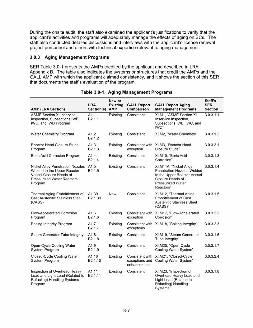
3-7
During the onsite audit, the staff also examined the applicant’s justifications to verify that the applicant’s activities and programs will adequately manage the effects of aging on SCs. The staff also conducted detailed discussions and interviews with the applicant’s license renewal project personnel and others with technical expertise relevant to aging management.
3.0.3 Aging Management Programs
SER Table 3.0-1 presents the AMPs credited by the applicant and described in LRA Appendix B. The table also indicates the systems or structures that credit the AMPs and the GALL AMP with which the applicant claimed consistency, and it shows the section of this SER that documents the staff’s evaluation of the program.
Table 3.0-1. Aging Management Programs
AMP (LRA Section) LRA Section(s)
New or Existing AMP
GALL Report Comparison
GALL Report Aging Management Programs
Staff’s SER Section
ASME Section XI Inservice Inspection, Subsections IWB, IWC, and IWD Program
A1.1 B2.1.1
Existing Consistent XI.M1, “ASME Section XI Inservice Inspection, Subsections IWB, IWC, and IWD”
3.0.3.1.1
Water Chemistry Program A1.2 B2.1.2
Existing Consistent XI.M2, “Water Chemistry“ 3.0.3.1.2
Reactor Head Closure Studs Program
A1.3 B2.1.3
Existing Consistent with exception
XI.M3, “Reactor Head Closure Studs”
3.0.3.2.1
Boric Acid Corrosion Program A1.4 B2.1.4
Existing Consistent XI.M10, “Boric Acid Corrosion”
3.0.3.1.3
Nickel-Alloy Penetration Nozzles Welded to the Upper Reactor Vessel Closure Heads of Pressurized Water Reactors Program
A1.5 B2.1.5
Existing Consistent XI.M11A, “Nickel-Alloy Penetration Nozzles Welded to the Upper Reactor Vessel Closure Heads of Pressurized Water Reactors”
3.0.3.1.4
Thermal Aging Embrittlement of Cast Austenitic Stainless Steel (CASS)
A1.39 B2.1.39
New Consistent XI.M12, “Thermal Aging Embrittlement of Cast Austenitic Stainless Steel (CASS)”
3.0.3.1.5
Flow-Accelerated Corrosion Program
A1.6 B2.1.6
Existing Consistent with exception
XI.M17, “Flow-Accelerated Corrosion”
3.0.3.2.2
Bolting Integrity Program A1.7 B2.1.7
Existing Consistent with exceptions
XI.M18, “Bolting Integrity” 3.0.3.2.3
Steam Generator Tube Integrity A1.8 B2.1.8
Existing Consistent XI.M19, “Steam Generator Tube Integrity”
3.0.3.1.6
Open-Cycle Cooling Water System Program
A1.9 B2.1.9
Existing Consistent XI.M20, “Open-Cycle Cooling Water System”
3.0.3.1.7
Closed-Cycle Cooling Water System Program
A1.10 B2.1.10
Existing Consistent with exceptions and enhancement
XI.M21, “Closed-Cycle Cooling Water System”
3.0.3.2.4
Inspection of Overhead Heavy Load and Light Load (Related to Refueling) Handling Systems Program
A1.11 B2.1.11
Existing Consistent XI.M23, “Inspection of Overhead Heavy Load and Light Load (Related to Refueling) Handling Systems”
3.0.3.1.8
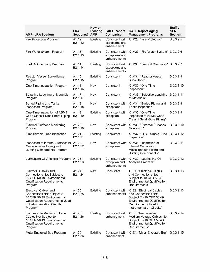
3-8
AMP (LRA Section) LRA Section(s)
New or Existing AMP
GALL Report Comparison
GALL Report Aging Management Programs
Staff’s SER Section
Fire Protection Program A1.12 B2.1.12
Existing Consistent with exceptions and enhancement
XI.M26, “Fire Protection” 3.0.3.2.5
Fire Water System Program A1.13 B2.1.13
Existing Consistent with exceptions and enhancements
XI.M27, “Fire Water System” 3.0.3.2.6
Fuel Oil Chemistry Program A1.14 B2.1.14
Existing Consistent with exceptions and enhancements
XI.M30, “Fuel Oil Chemistry" 3.0.3.2.7
Reactor Vessel Surveillance Program
A1.15 B2.1.15
Existing Consistent XI.M31, “Reactor Vessel Surveillance”
3.0.3.1.9
One-Time Inspection Program A1.16 B2.1.16
New Consistent XI.M32, “One-Time Inspection”
3.0.3.1.10
Selective Leaching of Materials Program
A1.17 B2.1.17
New Consistent XI.M33, “Selective Leaching of Materials”
3.0.3.1.11
Buried Piping and Tanks Inspection Program
A1.18 B2.1.18
New Consistent with exceptions
XI.M34, “Buried Piping and Tanks Inspection”
3.0.3.2.8
One-Time Inspection of ASME Code Class 1 Small-Bore Piping Program
A1.19 B2.1.19
Existing Consistent with exception
XI.M35, “One-Time Inspection of ASME Code Class 1 Small-Bore Piping”
3.0.3.2.9
External Surfaces Monitoring Program
A1.20 B2.1.20
New Consistent with exception
XI.M36, ”External Surfaces Monitoring"
3.0.3.2.10
Flux Thimble Tube Inspection A1.21 B2.1.21
Existing Consistent XI.M37, “Flux Thimble Tube Inspection”
3.0.3.1.12
Inspection of Internal Surfaces in Miscellaneous Piping and Ducting Components Program
A1.22 B2.1.22
New Consistent with exceptions
XI.M38, “Inspection of Internal Surfaces in Miscellaneous Piping and Ducting Components”
3.0.3.2.11
Lubricating Oil Analysis Program A1.23 B2.1.23
Existing Consistent with exception and enhancements
XI.M39, “Lubricating Oil Analysis Program”
3.0.3.2.12
Electrical Cables and Connections Not Subject to 10 CFR 50.49 Environmental Qualification Requirements Program
A1.24 B2.1.24
New Consistent XI.E1, “Electrical Cables and Connections Not Subject to 10 CFR 50.49 Environmental Qualification Requirements”
3.0.3.1.13
Electrical Cables and Connections Not Subject to 10 CFR 50.49 Environmental Qualification Requirements Used in Instrumentation Circuits Program
A1.25 B2.1.25
Existing Consistent with enhancements
XI.E2, “Electrical Cables and Connections Not Subject To 10 CFR 50.49 Environmental Qualification Requirements Used in Instrumentation Circuits”
3.0.3.2.13
Inaccessible Medium Voltage Cables Not Subject to 10 CFR 50.49 Environmental Qualification Requirements Program
A1.26 B2.1.26
Existing Consistent with enhancement
XI.E3, “Inaccessible Medium-Voltage Cables Not Subject To 10 CFR 50.40 Environmental Qualification Requirements”
3.0.3.2.14
Metal Enclosed Bus Program A1.36 B2.1.36
Existing Consistent with enhancement
XI.E4, “Metal Enclosed Bus” 3.0.3.2.15
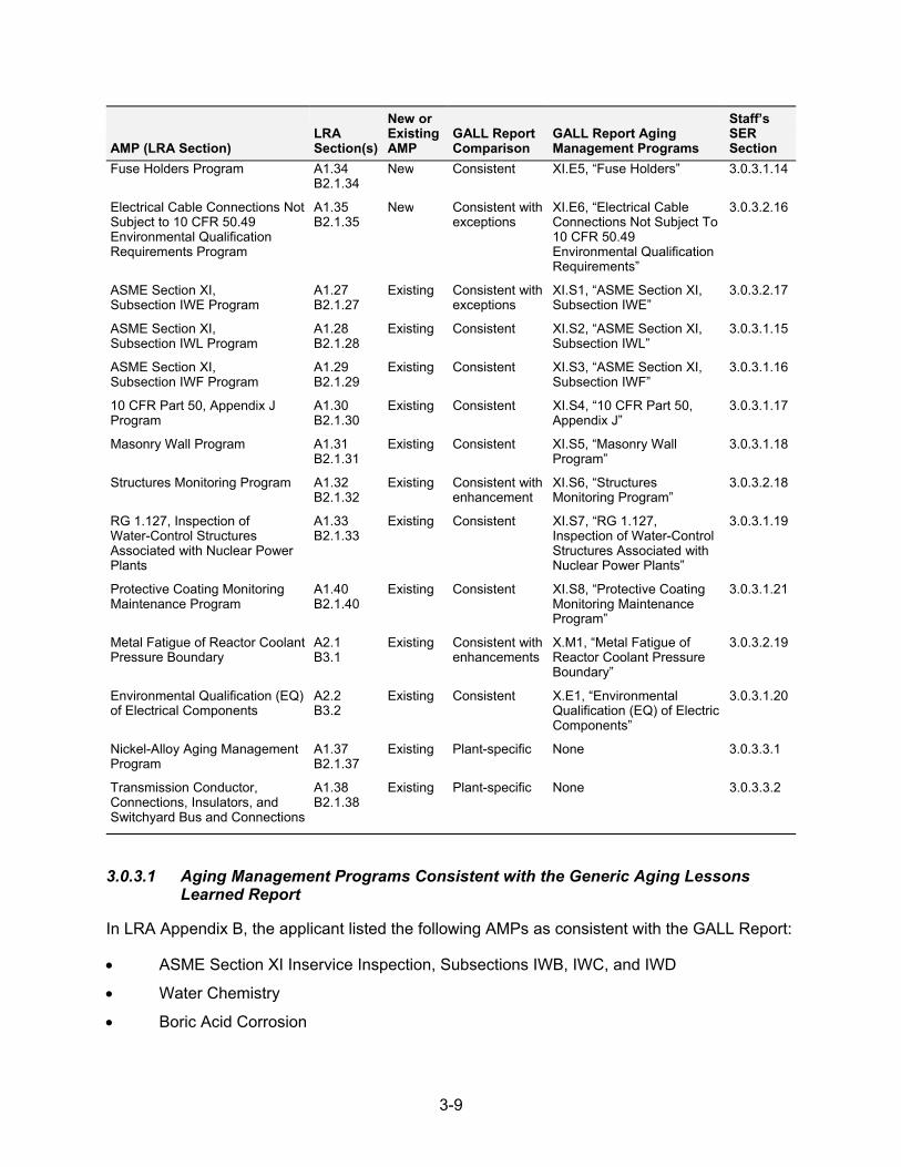
3-9
AMP (LRA Section) LRA Section(s)
New or Existing AMP
GALL Report Comparison
GALL Report Aging Management Programs
Staff’s SER Section
Fuse Holders Program A1.34 B2.1.34
New Consistent XI.E5, “Fuse Holders” 3.0.3.1.14
Electrical Cable Connections Not Subject to 10 CFR 50.49 Environmental Qualification Requirements Program
A1.35 B2.1.35
New Consistent with exceptions
XI.E6, “Electrical Cable Connections Not Subject To 10 CFR 50.49 Environmental Qualification Requirements”
3.0.3.2.16
ASME Section XI, Subsection IWE Program
A1.27 B2.1.27
Existing Consistent with exceptions
XI.S1, “ASME Section XI, Subsection IWE”
3.0.3.2.17
ASME Section XI, Subsection IWL Program
A1.28 B2.1.28
Existing Consistent XI.S2, “ASME Section XI, Subsection IWL”
3.0.3.1.15
ASME Section XI, Subsection IWF Program
A1.29 B2.1.29
Existing Consistent XI.S3, “ASME Section XI, Subsection IWF”
3.0.3.1.16
10 CFR Part 50, Appendix J Program
A1.30 B2.1.30
Existing Consistent XI.S4, “10 CFR Part 50, Appendix J”
3.0.3.1.17
Masonry Wall Program A1.31 B2.1.31
Existing Consistent XI.S5, “Masonry Wall Program”
3.0.3.1.18
Structures Monitoring Program A1.32 B2.1.32
Existing Consistent with enhancement
XI.S6, “Structures Monitoring Program”
3.0.3.2.18
RG 1.127, Inspection of Water-Control Structures Associated with Nuclear Power Plants
A1.33 B2.1.33
Existing Consistent XI.S7, “RG 1.127, Inspection of Water-Control Structures Associated with Nuclear Power Plants”
3.0.3.1.19
Protective Coating Monitoring Maintenance Program
A1.40 B2.1.40
Existing Consistent XI.S8, “Protective Coating Monitoring Maintenance Program”
3.0.3.1.21
Metal Fatigue of Reactor Coolant Pressure Boundary
A2.1 B3.1
Existing Consistent with enhancements
X.M1, “Metal Fatigue of Reactor Coolant Pressure Boundary”
3.0.3.2.19
Environmental Qualification (EQ) of Electrical Components
A2.2 B3.2
Existing Consistent X.E1, “Environmental Qualification (EQ) of Electric Components”
3.0.3.1.20
Nickel-Alloy Aging Management Program
A1.37 B2.1.37
Existing Plant-specific None 3.0.3.3.1
Transmission Conductor, Connections, Insulators, and Switchyard Bus and Connections
A1.38 B2.1.38
Existing Plant-specific None 3.0.3.3.2
3.0.3.1 Aging Management Programs Consistent with the Generic Aging Lessons Learned Report
In LRA Appendix B, the applicant listed the following AMPs as consistent with the GALL Report:
ASME Section XI Inservice Inspection, Subsections IWB, IWC, and IWD
Water Chemistry
Boric Acid Corrosion

3-10
Nickel-Alloy Penetration Nozzles Welded to the Upper Reactor Vessel Closure Heads of Pressurized Water Reactors
Thermal Aging Embrittlement of Cast Austenitic Stainless Steel (CASS)
Steam Generator Tube Integrity
Open-Cycle Cooling Water System
Inspection of Overhead Heavy Load and Light Load (Related to Refueling) Handling Systems
Reactor Vessel Surveillance
One-Time Inspection
Selective Leaching of Materials
Flux Thimble Tube Inspection
Electrical Cables and Connections Not Subject to 10 CFR 50.49 Environmental Qualification Requirements
Fuse Holders
ASME Section XI, Subsection IWL
ASME Section XI, Subsection IWF
10 CFR Part 50, Appendix J
Masonry Wall Program
RG 1.127, Inspection of Water-Control Structures Associated with Nuclear Power Plants
Protective Coating and Monitoring Maintenance
Environmental Qualification (EQ) of Electrical Components
3.0.3.1.1 ASME Section XI Inservice Inspection, Subsections IWB, IWC, and IWD
Summary of Technical Information in the Application. In LRA Section B2.1.1, the applicant described the existing ASME Section XI Inservice Inspection, Subsections IWB, IWC, and IWD Program as consistent with GALL AMP XI.M1, “ASME Section XI Inservice Inspection, Subsections IWB, IWC, and IWD.” The applicant stated that the inspections under this program manage cracking, loss of fracture toughness, and loss of material in Class 1, 2, and 3 piping and components within the scope of license renewal. The applicant further stated that the program includes periodic visual, surface, volumetric examinations, and leakage tests of ASME Code Class 1, 2, and 3 pressure-retaining components listed in ASME Section XI Tables IWB-2500-1, IWC-2500-1, and IWD-2500-1, respectively. The applicant also stated that it is following Inspection Program B as allowed by the ASME Code and includes the respective requirements for scheduling the examinations and tests for Class 1, 2, and 3 components. The applicant noted two of its other AMPs, Reactor Head Closure Studs Program and ASME Section XI, Subsection IWF Program, supplement this AMP. Further, the applicant stated that it evaluates every indication, dispositions identified flaws or indications according to the applicable ASME Code acceptance criteria, and revises the scope of inspection based on the results. The applicant also stated that it reexamines the allowable flaws or indications and relevant conditions left in service during subsequent inspections.
3-11
Staff Evaluation. During its audit and review, the staff reviewed the applicant’s claim of consistency with the GALL Report. The staff also reviewed the plant conditions to determine if they are bounded by the conditions for which the GALL Report was evaluated.
The staff compared elements one through six of the applicant’s program to the corresponding elements of GALL AMP XI.M1. As discussed in the Audit Report, the staff confirmed that each element of the applicant’s program is consistent with the corresponding element of GALL AMP XI.M1, with the exception of the “detection of aging effects” and “acceptance criteria” program elements, and the program description. For items related to these, the staff determined the need for additional clarification, which resulted in the issuance of requests for additional information (RAIs).
LRA Section B2.1.1 states, “[i]n conformance with 10 CFR 50.55a(g)(4)(ii), the DCPP ISI Program is updated each successive 120-month inspection interval to comply with the requirements of the latest edition of the ASME Code specified 12 months before the start of the inspection interval.” It was not clear to the staff if the applicant was referring to the statements of consideration (SOC) for the update of 10 CFR 50.55a to justify use of a more recent edition of the ASME Code. By letter dated June 14, 2010, the staff issued RAI B2.1.3-1, asking that the applicant supply information to clarify if the ASME Code edition, to be incorporated by the applicant for the future 120-month inspection interval during the period of extended operation, would be the ASME Section XI Code editions and addenda, as modified and limited in the 10 CFR 50.55a rule, that are considered acceptable in the Federal Register Notice (FRN) for future 10 CFR 50.55a amendments.
In its response dated July 7, 2010, the applicant stated, in part, that “…for the future 120-month lSI intervals, which will be implemented during the period of extended operation, PG&E will incorporate the editions and addenda of the ASME Code that will be endorsed for use in 10 CFR 50.55a (as modified and subject to any limitations in rule) and be acceptable for the license renewal as referenced in the Statements of Consideration on the update of 10 CFR 50.55a and published in the Federal Register.”
Based on its review, the staff finds the applicant’s response to RAI B2.1.3-1 acceptable because it clarifies the proper referencing of the applicable ASME Code editions and applicant’s usage of future 10 CFR 50.55a amendments as required by 10 CFR 50.55a, and clarified by the FRN. The staff’s concern described in RAI B2.1.3-1 is resolved.
In LRA Section B2.1.1, the applicant stated that it evaluates every indication; however, the acceptance standards IWD-3400 and IWD-3500 and the flaw evaluation standard IWD-3600, in the case of Class 3 components, are not included in LRA Section B2.1.1. The staff noted that this omission is not consistent with the “acceptance criteria” program element of GALL AMP XI.M1, which states, in part, that any indication or relevant conditions of degradation detected are evaluated for Class 3 components. It was not clear to the staff if, or how, the applicant was evaluating Class 3 components differently from these standards. In addition, the staff noted that the inspections of Class 1 small-bore piping including socket welds are covered under the “detection of aging effects” program element of GALL AMP XI.M1. However, this coverage was not apparent in the applicant’s ASME Section XI Inservice Inspection, Subsections IWB, IWC, and IWD Program. The staff noted that some of this may be covered by the applicant under its One-Time Inspection of ASME Code Class 1 Small-Bore Piping Program, but this was not referenced in LRA Section B2.1.1. By letter dated June 14, 2010, the staff issued RAI B2.1.1-1, asking that the applicant explain how the “program description” includes the use of acceptance and evaluation standards for Class 3 components. The staff also requested that the applicant explain which AMP covers or supplements the inspections of
3-12
Class 1 small-bore piping and socket welds. The staff also asked that the applicant justify the use of this program.
In its response dated July 7, 2010, the applicant amended LRA Section B2.1.1 to explicitly incorporate the acceptance standards IWD-3400 and IWD-3500 and the flaw evaluation standard IWD-3600 for Class 3 components.
The applicant also clarified that the detection of aging effects for Class 1 small-bore piping is described in LRA Section B2.1.19, “One-Time Inspection of ASME Code Class 1 Small-Bore Piping Program,” implemented as part of the fourth interval of its Inservice Inspection (lSI) Program. Based on the clarifications, the staff’s stated concerns about the “detection of aging effects” program element are resolved.
Based on its review, the staff finds the applicant’s response to RAI B2.1.1-1 acceptable because it addressed the omission in the LRA and amended it so that it is consistent with the “acceptance criteria” program element of GALL AMP XI.M1. The applicant also clarified that the recommendation of inspecting Class 1 small-bore piping in the “detection of aging effects” program element will be performed under its One-Time Inspection of ASME Code Class 1 Small-Bore Piping Program. The staff’s concern described in RAI B2.1.1-1 is resolved.
Based on its audit and review of the applicant’s responses to the RAIs B2.1.1-1 and B2.1.3-1, the staff finds that elements one through six of the applicant’s ASME Section XI Inservice Inspection, Subsections IWB, IWC, and IWD Program are consistent with the corresponding program elements of GALL AMP XI.M1 and, therefore, are acceptable.
Operating Experience. LRA Section B2.1.1 summarizes operating experience related to the ASME Section XI Inservice Inspection, Subsections IWB, IWC, and IWD Program. The applicant stated that it evaluates the results of inspections and carries out corrective actions to ensure the program operability through prompt identification and documentation of the relevant conditions. The applicant further stated that its review of the second 10-year ISI Interval Summary Reports showed that no age-related Code repairs or Code replacements were required for continued service of the components under ASME Section XI Tables IWB-2500-1, IWC-2500-1, and IWD-2500-1.
The staff reviewed operating experience information, in the application and during the audit, to determine if the applicant reviewed the applicable aging effects and industry and plant-specific operating experience. As discussed in the Audit Report, the staff conducted an independent search of the plant-specific operating experience information to determine if the applicant had adequately incorporated and evaluated operating experience related to this program. During its review, the staff found operating experience showing that the applicant’s program may not be effective in adequately managing aging effects during the period of extended operation. The staff determined the need for additional clarification, which resulted in the issuance of an RAI.
LRA Section B2.1.1 notes an instance of intergranular stress corrosion cracking (IGSCC) in accumulator nozzles, identified in 1987 [in the first 10-year ISI Interval], stating that all nozzles were inspected and those with unacceptable indications were (subsequently, in the Unit 1, fifth refueling outage (RO) and Unit 2, fifth RO) weld-repaired or replaced with nozzles made of a new material.
The staff noted that the applicant carried out corrective actions; however, the applicant included only the visual examination for replaced parts but not an ultrasonic (UT) examination, as in the case for original parts, in its long-term inspection plan. By letter dated June 14, 2010, the staff issued RAI B2.1.1-2 asking that the applicant justify why it only performs a visual inspection on
3-13
the replaced nozzles and underskirt piping, and not UT, as part of the long-term inspection plan for aging management.
In its response dated July 7, 2010, the applicant stated that the original nozzles were made of Type 304 stainless steel with partial penetration welds that were subject to vessel heat treatment. The applicant stated these conditions are quite likely to have produced the sensitized microstructure susceptible to the IGSCC incidence along with the higher propensity for crack initiation due to partial penetration and likely contaminants during their initial fabrication and testing. The applicant also indicated that, in subsequent outages, it inspected all original nozzles by detailed volumetric and surface examinations with corrective actions including replacements. The applicant stated that the replacements were made of more crack-resistant 304L grade material with fillet weld geometry under controlled conditions to minimize contaminants. The staff finds this to be reasonable for assuring that the major causal factors for IGSCC in the original nozzles are not present in the replacements; therefore, enhanced inspections beyond those required by the ASME Code are not needed. Nonetheless, the applicant has continued to perform UT inspections on the remaining original nozzles.
Based on its review, the staff finds the applicant’s response to RAI B2.1.1-2 acceptable based on the combination of design changes that reduced susceptibility to cracking and the inspection strategy carried out by the applicant for original and replaced parts. The staff’s concern described in RAI B2.1.1-2 is resolved.
Based on its audit and review of the application and review of the applicant’s response to RAI B2.1.1-2, the staff finds that operating experience related to the applicant’s program for this AMP shows that the applicant can adequately manage the effects of aging on SSCs within the scope of this AMP and that implementation of the program has resulted in the applicant taking corrective actions. The staff confirmed that the “operating experience” program element satisfies the criteria in SRP-LR Section A.1.2.3.10 and, therefore, the staff finds this program element acceptable.
FSAR Supplement. LRA Section A1.1 supplies the FSAR supplement for the ASME Section XI Inservice Inspection, Subsections IWB, IWC, and IWD Program. The staff reviewed this FSAR supplement description of the program against the recommended description for this type of program as described in SRP-LR Table 3.1-2. The staff determines that the information in the FSAR supplement is an adequate summary description of the program, as required by 10 CFR 54.21(d).
Conclusion. On the basis of its review of the applicant’s ASME Section XI Inservice Inspection, Subsections IWB, IWC, and IWD Program, the staff finds all program elements consistent with the GALL Report. The staff concludes that the applicant has demonstrated that the effects of aging will be adequately managed so that the intended function(s) will be maintained consistent with the CLB for the period of extended operation, as required by 10 CFR 54.21(a)(3). The staff also reviewed the FSAR supplement for this AMP and concludes that it provides an adequate summary description of the program, as required by 10 CFR 54.21(d).
3.0.3.1.2 Water Chemistry
Summary of Technical Information in the Application. LRA Section B2.1.2 describes the existing Water Chemistry Program as consistent with GALL AMP XI.M2, “Water Chemistry.” The applicant stated that its Water Chemistry Program is consistent with Electric Power Research Institute (EPRI) Technical Report (TR)-105714, PWR Primary Water Chemistry Guidelines, Revision 6, and EPRI TR-102134, PWR Secondary Water Chemistry Guidelines, Revision 7, for the primary and secondary chemical environments, respectively. The applicant
3-14
also stated that its Water Chemistry Program manages loss of material due to general, pitting, and crevice corrosion as well as stress corrosion cracking (SCC) in the primary and secondary water systems using the following principles:
limiting the concentration of chemical species known to cause corrosion
adding chemicals which inhibit degradation by influencing pH and dissolved oxygen levels
The applicant further stated that it will perform a one-time inspection of a representative group of components in low flow areas to verify the effectiveness of the Water Chemistry Program in these low flow areas.
Staff Evaluation. During its audit, the staff reviewed the applicant’s claim of consistency with the GALL Report. The staff also reviewed the plant conditions to determine if they are bounded by the conditions for which the GALL Report was evaluated.
The staff compared elements one through six of the applicant’s program to the corresponding elements of GALL AMP XI.M2. As discussed in the Audit Report, the staff confirmed that these elements are consistent with the corresponding elements of GALL AMP XI.M2. Based on its audit, the staff finds that elements one through six of the applicant’s Water Chemistry Program are consistent with the corresponding program elements of GALL AMP XI.M2 and, therefore, are acceptable.
Operating Experience. LRA Section B2.1.2 summarizes operating experience related to the Water Chemistry Program. The applicant stated that it has had only transient out-of-specification (OOS) chemistry parameters in the primary water system, and evaluations determined the transient events did not have any negative long-term effects on plant components. The applicant provided several plant-specific examples of operating experience related to secondary water system chemistry control, of which two are summarized below.
The applicant stated that during the period from May 1999–March 2005, it detected OOS dissolved oxygen in the condensate systems during routine sampling. The applicant determined that the cause of the OOS dissolved oxygen was from air-in leakage from the condensate booster pump boots and the main feedwater pump turbine exhaust boots. The applicant also stated that it implemented a nitrogen supply to the condenser and condensate pump suction piping and installed mechanical seals on the main feedwater pump turbine exhausts as a corrective action. The applicant further stated that since these corrective actions were completed, no OOS dissolved oxygen problems have been reported for the condensate system.
The applicant stated that during the period from March 1997–January 2001, it detected OOS hydrazine levels in the Units 1 and 2 feedwater systems, using routine sampling. The applicant also stated that it found the cause of the OOS hydrazine to be nitrogen binding in the pump suction lines, and it modified the configuration of the suction piping to vent the suction lines back to the hydrazine day tank as a corrective action. The applicant further stated that since the corrective action was completed, no OOS hydrazine problem reports attributable to nitrogen gas binding have been made.
The staff reviewed operating experience information, in the application and during the audit, to determine if the applicable aging effects and industry and plant-specific operating experience were reviewed by the applicant and are evaluated in the GALL Report. As discussed in the Audit Report, the staff conducted an independent search of the plant-specific operating experience information to determine if the applicant had adequately incorporated and evaluated
3-15
operating experience related to this program. During its review, the staff found no operating experience to indicate that the applicant’s program would not be effective in adequately managing aging effects during the period of extended operation.
Based on its audit and review of the application, the staff finds that operating experience related to the applicant’s program demonstrates that it can adequately manage the detrimental effects of aging on SSCs within the scope of the program and that implementation of the program has resulted in the applicant taking corrective actions. The staff confirmed that the “operating experience” program element satisfies the criteria in SRP-LR Section A.1.2.3.10 and, therefore, the staff finds it acceptable.
FSAR Supplement. LRA Section A1.2 supplies the FSAR supplement for the Water Chemistry Program. The staff reviewed this FSAR supplement description of the program and notes that it conforms to the recommended description for this type of program, as described in SRP-LR Tables 3.1-2, 3.2-2, 3.3-2, 3.4-2, and 3.5-2. The staff determines that the information in the FSAR supplement is an adequate summary description of the program, as required by 10 CFR 54.21(d).
Conclusion. On the basis of its review of the applicant’s Water Chemistry Program, the staff finds all program elements consistent with the GALL Report. The staff concludes that the applicant has demonstrated that the effects of aging will be adequately managed so that the intended function(s) will be maintained consistent with the CLB for the period of extended operation, as required by 10 CFR 54.21(a)(3). The staff also reviewed the FSAR supplement for this AMP and concludes that it provides an adequate summary description of the program, as required by 10 CFR 54.21(d).
3.0.3.1.3 Boric Acid Corrosion
Summary of Technical Information in the Application. LRA Section B2.1.4 describes the existing Boric Acid Corrosion Program as consistent with GALL AMP XI.M10, “Boric Acid Corrosion.” The applicant stated that the program monitors in-scope components that are susceptible to boric acid corrosion and ensures that corrosion caused by leaking treated borated water or reactor coolant does not lead to degradation of the leakage source or adjacent SCs in the leakage path. The applicant also stated that the program includes provisions to inspect for evidence of leakage, evaluate the leakage source and surrounding area, and initiate corrective actions.
Staff Evaluation. During its audit, the staff reviewed the applicant’s claim of consistency with the GALL Report. The staff also reviewed the plant conditions to determine if they are bounded by the conditions for which the GALL Report was evaluated.
The staff compared elements one through six of the applicant’s program to the corresponding element of GALL AMP XI.M10. As discussed in the Audit Report, the staff confirmed that these elements are consistent with the corresponding elements of GALL AMP XI.M10. Based on its audit, the staff finds that elements one through six of the applicant’s Boric Acid Corrosion Program are consistent with the corresponding program elements of GALL AMP XI.M10 and, therefore, are acceptable.
Operating Experience. LRA Section B2.1.4 summarizes operating experience related to the Boric Acid Corrosion Program. The applicant stated that its inspections of the RV head, which were performed in accordance with the NRC’s first revised Order EA-03-009, found minor localized dry boric acid deposits on small valve packing glands and seals above the reactor head. According to the applicant, it corrected these minor leaks and did not find leakage from
3-16
pressure-retaining components above the reactor head. The applicant also stated that it found no evidence of boron, corrosion products, head material wastage or leaking, or cracked nozzles. The applicant further stated that it conducted Quality Verification assessments in 2003, 2005, and 2007 to examine the program effectiveness, implementation of industry guidance, and other program metrics and incorporated the recommendations generated in these assessments to improve the program. The applicant concluded by stating that adherence to established guidelines for systematic prevention, detection, monitoring, and corrective action demonstrates that the Boric Acid Corrosion Program will adequately manage the effects of aging to maintain the intended functions of SCs during the period of extended operation.
The staff reviewed operating experience information, in the application during the audit, to determine if the applicable aging effects and industry and plant-specific operating experience were reviewed by the applicant and are evaluated in the GALL Report. As discussed in the Audit Report, the staff conducted an independent search of the plant-specific operating experience information to determine if the applicant had adequately incorporated and evaluated operating experience related to this program. During its review, the staff found no operating experience to indicate that the applicant’s program would not be effective in adequately managing aging effects during the period of extended operation.
Based on its audit and review of the application, the staff finds that operating experience related to the applicant’s program demonstrates that the applicant can adequately manage the detrimental effects of aging on SSCs within the scope of the program and implementation of the program has resulted in the applicant taking corrective actions. The staff confirmed that the “operating experience” program element satisfies the criteria in SRP-LR Section A.1.2.3.10 and, therefore, the staff finds it acceptable.
FSAR Supplement. LRA Section A1.4 supplies the FSAR supplement for the Boric Acid Corrosion Program. The staff reviewed this FSAR supplement description of the program and notes that it conforms to the recommended description for this type of program, as described in SRP-LR Tables 3.1-2, 3.2-2, 3.3-2, 3.4-2, 3.5-2, and 3.6-2. The staff determines that the information in the FSAR supplement is an adequate summary description of the program, as required by 10 CFR 54.21(d).
Conclusion. On the basis of its review of the applicant’s Boric Acid Corrosion Program, the staff finds all program elements consistent with the GALL Report. The staff concludes that the applicant has demonstrated that the effects of aging will be adequately managed so that the intended function(s) will be maintained consistent with the CLB for the period of extended operation, as required by 10 CFR 54.21(a)(3). The staff also reviewed the FSAR supplement for this AMP and concludes that it provides an adequate summary description of the program, as required by 10 CFR 54.21(d).
3.0.3.1.4 Nickel-Alloy Penetration Nozzles Welded to the Upper Reactor Vessel Closure Heads of Pressurized Water Reactors
Summary of Technical Information in the Application. LRA Section B2.1.5 describes the Nickel-Alloy Penetration Nozzles Welded to the Upper Reactor Vessel Closure Heads of Pressurized Water Reactors Program that manages cracking due to primary water stress corrosion cracking (PWSCC) and loss of material due to boric acid wastage for nickel-alloy components in the upper reactor pressure vessel head. The program meets the GALL Report recommendation to have a plant-specific program for managing nickel-alloy materials to comply with the applicable NRC publications and industry guidelines.
3-17
The applicant noted that this program is an existing program that is consistent with GALL AMP XI.M11A, “Nickel-Alloy Penetration Nozzles Welded to the Upper Reactor Closure Heads of Pressurized Water Reactors.” In addition, the applicant noted that the Unit 2 RPV head was replaced during the October 2009 RO, and the Unit 1 RPV head is scheduled for replacement during the October 2010 RO. The staff noted that the Unit 1 RPV head was replaced as scheduled.
Staff Evaluation. The staff reviewed the applicant’s claim of consistency with the GALL Report. The staff also reviewed the plant conditions to determine whether they are bounded by the conditions for which the GALL Report was evaluated.
The staff compared elements one through six of the applicant’s program to the corresponding elements of GALL AMP XI.M11A. The staff confirmed that these elements are consistent with the corresponding elements of GALL AMP XI.M11A. Based on its review, the staff finds that elements one through six of the applicant’s Nickel-Alloy Penetration Nozzles Welded to the Upper Reactor Vessel Closure Heads of Pressurized Water Reactors Program are consistent with the corresponding program elements of GALL AMP XI.M11A and, therefore, acceptable.
The applicant made one change from the requirements of GALL AMP XI.M11A in regards to the implementation of the requirements of 10 CFR 50.55a(g)(6)(ii)(D) and ASME Code Case N-729-1 in lieu of the First Revised NRC Order EA-03-009, dated February 20, 2004 (Order). This is consistent with the current regulatory requirements for upper head penetration inspection as discussed in the following paragraphs.
From February 20, 2004, through December 31, 2008, the NRC regulatory requirement for reactor pressure vessel head inspections was contained under Order EA-03-009. Under this Order, a plant’s particular susceptibility to PWSCC was measured and ranked into High, Moderate, Low or Replaced categories. The Replaced category was for those plants that had their heads replaced. The other three categories were mainly based on a calculation of the head’s time at operating temperature.
On August 6, 2004, the NRC Commission, through a Staff Requirements Memorandum issued SECY-04-115, “Rulemaking Plan to Incorporate First Revised Order EA-03-009 Requirements into 10 CFR 50.55a,” directed the staff to evaluate anticipated ASME Code reactor pressure vessel inspection requirements for incorporation into 10 CFR 50.55a. Thereafter NRC staff participated in the development of ASME Code Case N-729. ASME Code Case N-729-1, revision 1 to the original N-729, was developed as the ASME Code consensus standard for the long-term inspection program of reactor pressure vessel heads and their associated penetration nozzles. 10 CFR 50.55a(g)(6)(ii)(D), effective by December 31, 2008, required the use of ASME Code Case N-729-1, as conditioned by the NRC, in lieu of the Order to define the requirements for reactor vessel head inspections.
The GALL Report, Vol. 2, Revision 1, which includes GALL AMP XI.M11A, was issued in September 2005, while upper head inspections were covered under the requirements of the Order. GALL AMP XI.M11A recommends compliance with the Order or any subsequent NRC requirements that may be established to supersede the requirements of the Order. As the current regulatory requirements have changed from the Order to the those listed under 10 CFR 50.55a(g)(6)(ii)(D) for the long-term inspection program for upper reactor pressure vessel heads, the staff noted that compliance with the new regulatory requirements under 10 CFR 50.55a(g)(6)(ii)(D) is consistent with the recommendations of GALL AMP XI.M11A.
Given the above basis for review of compliance with the intent of GALL AMP XI.M11A, the staff reviewed the applicant’s program to ensure compliance with the current long-term inspection
3-18
requirements for the upper reactor pressure vessel head. The applicant stated its program implemented ASME Code Case N-729-1 in accordance with 10 CFR 50.55a(g)(6)(ii)(D) and the NRC conditions of 10 CFR 50.55a(g)(6)(ii)(D)(2) through (6). These inspection requirements are applicable to both the previous and replaced upper reactor pressure vessel heads at both units.
Operating Experience. LRA Section B2.1.5 summarizes operating experience related to the applicant’s Nickel-Alloy Penetration Nozzles Welded to the Upper Reactor Vessel Closure Heads of Pressurized Water Reactors Program. The applicant stated that the Unit 2 RPV head was replaced during the October 2009 RO, and the Unit 1 RPV head is scheduled for replacement during the October 2010 RO. The staff noted that the Unit 1 RPV head was replaced as scheduled. The replacement heads contain penetration nozzles and associated welds made from Alloy 690 materials that are more resistant to PWSCC than the Alloy 600 materials used in the previous heads.
The staff reviewed operating experience information in the application to determine whether the applicable aging effects and industry and plant-specific operating experience were reviewed by the applicant and are evaluated in the GALL Report. During its review, the staff found no operating experience to indicate that the applicant’s program would not be effective in adequately managing aging effects during the period of extended operation.
Based on its review of the application, the staff finds that operating experience related to the applicant’s program demonstrates that it can adequately manage the detrimental effects of aging on SSCs within the scope of the program and that implementation of the program has resulted in the applicant taking corrective actions. The staff confirms that the “operating experience” program element satisfies the criterion in SRP-LR Section A.1.2.3.10 and, therefore, the staff finds it acceptable.
FSAR Supplement. In LRA Section A1.5, the applicant provided the FSAR supplement for the Nickel-Alloy Penetration Nozzles Welded to the Upper Reactor Vessel Closure Heads of Pressurized Water Reactors Program. The staff reviewed this FSAR supplement description of the program and notes that it conforms to the recommended description for this type of program as described in SRP-LR Table 3.1-2. The staff determines that the FSAR supplement contains an adequate summary description of the program, as required by 10 CFR 54.21(d).
Conclusion. On the basis of its review of the applicant’s Nickel-Alloy Penetration Nozzles Welded to the Upper Reactor Vessel Closure Heads of Pressurized Water Reactors Program, the staff finds all program elements consistent with the GALL Report. The staff concludes that the applicant has demonstrated that the effects of aging will be adequately managed so that the intended function(s) will be maintained consistent with the CLB for the period of extended operation, as required by 10 CFR 54.21(a)(3). The staff also reviewed the FSAR supplement for this AMP and concludes that it provides an adequate summary description of the program, as required by 10 CFR 54.21(d).
3.0.3.1.5 Thermal Aging Embrittlement of Cast Austenitic Stainless Steel
Summary of Technical Information in the Application. In LRA Section B2.1.39, the applicant described the new Thermal Aging Embrittlement of Cast Austenitic Stainless Steel (CASS) Program as consistent with GALL AMP XI.M12, “Thermal Aging Embrittlement of Cast Austenitic Stainless Steel (CASS).” The Thermal Aging Embrittlement of CASS Program manages embrittlement of susceptible CASS components due to thermal aging. The applicant stated that the program will be used to determine the susceptibility of CASS components to thermal aging embrittlement based on casting method, molybdenum content, and percent
3-19
ferrite. The Thermal Aging Embrittlement of CASS Program does not prevent degradation due to aging effects but provides measures for monitoring thermal aging embrittlement to detect the degradation before loss of intended function of the CASS components.
The applicant stated that for potentially susceptible components, aging management is accomplished through an enhanced volumetric examination that will be demonstrated to be adequate for CASS inspection in accordance with criteria identified in the ASME Section XI, Appendix VIII, or a component-specific flaw tolerance evaluation according to EPRI TR-106092, Appendix B guidelines. Additional inspection or evaluations to demonstrate that the CASS material has adequate fracture toughness will not be required for components that have been determined to not be susceptible to thermal aging embrittlement. The applicant stated further that flaws detected must be dispositioned in accordance with the acceptance criteria of the ASME Section XI. If a detected flaw size does not meet the acceptance criteria following a flaw evaluation, the applicant will repair or replace the degraded components in accordance with the ASME Section XI, IWA-4000. According to the applicant, the Thermal Aging Embrittlement of CASS Program is a new program and will be implemented as part of the ASME Section XI ISI program. The required inspections will be completed within the 10-year period prior to the period of extended operation.
Staff Evaluation. GALL AMP XI.M12 establishes the criteria for determining whether a supplemental flaw tolerance assessment or volumetric or enhanced VT-1 visual inspection techniques should be credited to manage reduction of fracture toughness due to thermal aging embrittlement in CASS RCS piping, piping components, or piping elements (including CASS valve bodies and CASS pump casings). The staff’s letter of May 19, 2000, “Thermal Aging Embrittlement of Cast Austenitic Stainless Steel Components,” provides criteria for determining whether a particular CASS material is susceptible to thermal aging embrittlement and describes aging management strategies for these materials. GALL AMP XI.M12 incorporated by reference the May 19, 2000, letter.
The CASS components that are within the scope of the AMP are described in LRA Table 3.1.2-2. The staff finds that the program elements in the Thermal Aging Embrittlement of CASS Program are consistent with the program element criteria recommended in GALL AMP XI.M12. However, the staff asked the applicant to clarify the following issues.
The staff noted that UT has not yet been qualified in accordance with the ASME Section XI, Appendix VIII, for the examination of CASS material. By letter dated August 26, 2010, the staff issued RAI B2.1.39-1, asking the applicant to discuss how CASS components will be inspected.
By letter dated September 24, 2010, the applicant responded, stating that the CASS components that are in scope of the Thermal Aging Embrittlement of CASS Program are currently pressure tested every refueling outage per the current ASME Section XI edition in effect. Current inspection practices will continue during the period of extended operation as required per the ASME Code editions in effect during the period of extended operation. In addition, for CASS components within the scope of license renewal that are determined to be susceptible to the aging effect of thermal embrittlement, aging management will be accomplished through either qualified volumetric examination, if one is demonstrated to be adequate for CASS inspection in accordance with criteria identified in ASME Section XI, Appendix VIII, or a component-specific flaw tolerance evaluation will be performed. This AMP is a new program and if a viable volumetric examination method is developed, it will be implemented as part of the ASME Section XI ISI Program. Additional inspection or evaluations to demonstrate that the material has adequate fracture toughness will not be required for components that have been determined to not be susceptible to thermal aging embrittlement.
3-20
The staff finds that the applicant will implement a qualified UT method or flaw tolerance evaluation to manage the aging of the CASS components. This is consistent with the guidance in GALL AMPXI.M12, and, therefore, is acceptable. The applicant has committed (Commitment No. 19) to implement the Thermal Aging Embrittlement of CASS Program during the 10 years prior to the period of extended operation. The staff finds this commitment acceptable because early implementation of the subject program will provide the opportunity for any potential inadequacy or deficiencies of the AMP to be identified and corrected early, before the plant enters into the period of extended operation. If the applicant chooses to use the flaw tolerance evaluation as part of the Thermal Aging Embrittlement of CASS Program to manage the aging of the CASS components, the staff will review the flaw tolerance evaluation methodology to determine its acceptability when it is available for staff review. The staff’s concern described in RAI B2.1.39-1 is resolved.
The staff noted that the CASS components may not be examined under the risk-informed ISI program. By letter dated August 26, 2010, the staff issued RAI B2.1.39-2, request 1, asking if the applicant has implemented the risk-informed lSI program and how the CASS components will be inspected under it.
By letter dated September 24, 2010, the applicant responded, stating that for the current 10-year lSI interval, it has implemented the risk-informed lSI Program for piping welds. The applicant stated further that current inspection practices (pressure tests) will continue during the period of extended operation as required by the ASME Code editions in effect during the period of extended operation. In addition, regardless of whether the ASME Code lSI Program for the period of extended operation is risk-informed for CASS components within the scope of license renewal that are determined to be susceptible to the aging effect of thermal embrittlement, aging management will be accomplished through a qualified volumetric examination, if one becomes available, once every 10 years. Alternatively, a component-specific flaw tolerance evaluation will be performed.
The staff finds that regardless of whether the ISI program is risk-informed or not, the CASS components will be managed and monitored for aging-related degradation; therefore, the applicant's approach is acceptable. The staff’s concern described in RAI B2.1.39-2 is resolved.
Operating Experience. In LRA Section B2.1.39, the applicant stated that AMP B2.1.39 is a new program. Therefore, plant-specific operating experience to verify the effectiveness of the program is not available. In its operating experience review, the applicant did not identify any thermal aging embrittlement in the DCPP reactor coolant system. The applicant stated that as additional industry and applicable plant-specific operating experience become available, the operating experience will be evaluated and appropriately incorporated into the AMP through the corrective action program (CAP) and Operating Experience Program. This ongoing review of operating experience will continue throughout the period of extended operation, and the results will be maintained onsite. This process will enhance the effectiveness of this new AMP by incorporating applicable operating experience and performing self assessments of the program.
The staff reviewed operating experience information in the application to determine whether the applicable aging effects and industry and plant-specific operating experience were reviewed by the applicant and are evaluated in the GALL Report. During its review, the staff found no operating experience to indicate that the applicant’s program would not be effective in adequately managing aging effects during the period of extended operation.
Based on its review of the application, the staff finds that operating experience related to the applicant’s program demonstrates that it can adequately manage the detrimental effects of aging on SSCs within the scope of the program and that implementation of the program has
3-21
resulted in the applicant taking corrective actions. The staff confirmed that the “operating experience” program element satisfies the criterion in SRP-LR Section A.1.2.3.10 and, therefore, the staff finds it acceptable.
FSAR Supplement. In LRA Section A1.39, the applicant provided the FSAR supplement for the Thermal Aging Embrittlement of CASS Program. The staff reviewed this FSAR supplement description of the program and notes that it conforms to the recommended description for this type of program as described in SRP-LR Table 3.1-2. The staff determines that the FSAR supplement contains an adequate summary description of the program, as required by 10 CFR 54.21(d).
Conclusion. On the basis of its review of the applicant’s Thermal Aging Embrittlement of CASS Program, the staff finds all program elements consistent with the GALL Report. The staff concludes that the applicant has demonstrated that the effects of aging will be adequately managed so that the intended function(s) will be maintained consistent with the CLB for the period of extended operation, as required by 10 CFR 54.21(a)(3). The staff also reviewed the FSAR supplement for this AMP and concludes that it provides an adequate summary description of the program, as required by 10 CFR 54.21(d).
3.0.3.1.6 Steam Generator Tube Integrity
Summary of Technical Information in the Application. LRA Section B2.1.8 describes the existing Steam Generator Tube Integrity Program as consistent with GALL AMP XI.M19, “Steam Generator Tube Integrity.” The applicant stated that the Steam Generator Tube Integrity Program manages the aging of steam generator (SG) tubes, plugs, and tube supports.
The applicant stated the following:
The program includes the preventive measures, inspections, degradation assessment, condition monitoring, operational assessment, tube plugging, and leakage monitoring activities necessary to manage potential steam generator tube degradation, including mechanically induced phenomena, such as wear and impingement damage. The aging management measures employed includes nondestructive examinations [NDEs], visual inspection, sludge removal, tube plugging, in-situ pressure testing and maintaining the chemistry environment by removal of impurities and addition of chemicals to control pH and oxygen. NDE inspection scope and frequency, and primary to secondary leak rate monitoring are conducted consistent with the requirements of DCPP Units 1 and 2 Technical Specifications [TS] and NEI 97-06, Steam Generator Program Guidelines. Tube structural integrity limits are applied consistent with Regulatory Guide [RG] 1.121, Bases for Plugging Degraded PWR Steam Generator Tubes, August 1976.
Staff Evaluation. During its audit, the staff reviewed the applicant’s claim of consistency with the GALL Report. The staff also reviewed the plant conditions to determine if they are bounded by the conditions for which the GALL Report was evaluated.
The staff compared elements one through six of the applicant’s program to the corresponding elements of GALL Report XI.M19. As discussed in the Audit Report, the staff confirmed that these elements are consistent with the corresponding elements of GALL AMP XI.M19. However, the staff did find the need for clarification of the program description, in which the applicant stated that the tubing and secondary internals are not susceptible to corrosion due to advanced material design. By letter dated June 14, 2010, the staff issued RAI B2.1.8-1 asking that the applicant clarify this statement to indicate that the tube and secondary internals are
3-22
more corrosion resistant than in earlier SG designs. In its response dated July 7, 2010, the applicant revised the program description. The staff found the revised description acceptable, because it accurately describes the corrosion resistance of Alloy 690 materials; therefore, the issue described in RAI B2.1.8-1 is resolved. During the audit, the staff also requested a number of clarifications pertaining to plant procedures. As described in the Audit Report, the applicant agreed to these clarifications and initiated appropriate procedure changes.
Operating Experience. LRA Section B2.1.8 summarizes operating experience related to the Steam Generator Tube Integrity Program. The applicant replaced the original SGs in Units 1 and 2 in 2009 and 2008, respectively. The original SGs in both units were replaced with Westinghouse Model D54 SGs with thermally-treated Alloy 690 tubes. The applicant stated that the operating experience findings for this program identified no unique plant-specific operating experience; therefore, DCPP operating experience is consistent with the GALL Report. The applicant also stated that as additional industry and applicable plant-specific operating experience become available, it will evaluate and appropriately incorporate this experience into the program through the Corrective Action and Operating Experience Programs. The applicant further stated that the ongoing review of operating experience will continue throughout the period of extended operation, the results will be maintained onsite, and this process will confirm the effectiveness of this AMP by incorporating applicable operating experience and performing self-assessments of the program. The applicant included the following as part of the operating experience:
All degradation indications to date are from wear (fretting) due to loose parts, tube supports, anti-vibration bars, and manufacturing or handling anomalies. The tubing and secondary internals in these units are not susceptible to corrosion due to advanced material design.
The staff reviewed operating experience information, in the application and during the audit, to determine if the applicable aging effects and industry and plant-specific operating experience were reviewed by the applicant and are evaluated in the GALL Report. During its review, the staff found no operating experience to indicate that the applicant’s program would not be effective in adequately managing aging effects during the period of extended operation.
The staff confirmed that the applicant addressed operating experience identified after issuance of the GALL Report. Based on its audit and review of the application, the staff finds that operating experience related to the applicant’s program demonstrates that it can adequately manage the detrimental effects of aging on SSCs within the scope of the program and implementation of this program has resulted in the applicant taking corrective actions. The staff confirmed that the “operating experience” program element satisfies the criteria in SRP-LR Section A.1.2.3.10, and the staff finds it acceptable.
FSAR Supplement. LRA Section A1.8 provides the FSAR supplement for the Steam Generator Tube Integrity Program. The staff reviewed this FSAR supplement description of the program and notes that it conforms to the recommended description for this type of program as described in SRP-LR Table 3.1-2. The staff determines that the information in the FSAR supplement is an adequate summary description of the program, as required by 10 CFR 54.21(d).
Conclusion. On the basis of its review of the applicant’s Steam Generator Tube Integrity Program, the staff finds all program elements consistent with the GALL Report. The staff concludes that the applicant has demonstrated that the effects of aging will be adequately managed so that the intended function(s) will be maintained consistent with the CLB for the period of extended operation, as required by 10 CFR 54.21(a)(3). The staff also reviewed the
3-23
FSAR supplement for this AMP and concludes that it provides an adequate summary description of the program, as required by 10 CFR 54.21(d).
3.0.3.1.7 Open-Cycle Cooling Water System
Summary of Technical Information in the Application. LRA Section B2.1.9 describes the existing Open-Cycle Cooling Water System Program, as consistent with GALL AMP XI.M20, “Open-Cycle Cooling Water System.” The applicant stated that this program manages cracking, loss of material, and reduction of heat transfer for components exposed to the raw water from the auxiliary saltwater (ASW) system. The applicant also stated that the program includes surveillance and control techniques to manage aging effects caused by biofouling, corrosion, erosion, failure of protective coatings, and silting. The applicant further stated that these surveillances include periodic visual inspection and NDEs, and the program is consistent with the commitments established in responses to NRC Generic Letter (GL) 89-13.
Staff Evaluation. During its audit, the staff reviewed the applicant’s claim of consistency with the GALL Report. The staff also reviewed the plant conditions to determine if they are bounded by the conditions for which the GALL Report was evaluated.
The staff compared elements one through six of the applicant’s program to the corresponding elements of GALL AMP XI.M20. As discussed in the Audit Report, the staff confirmed that each element of the applicant’s program is consistent with the corresponding element of GALL AMP XI.M20, with the exception of the “detection of aging effects” program element. For this element, the staff identified the need for additional clarification, which resulted in the issuance of an RAI.
GALL AMP XI.M20 recommends that the program includes inspections for detecting degraded material condition but does not specifically address cracking. The applicant’s Open-Cycle Cooling Water System Program describes how the applicant will find cracking in coatings through visual inspections, but it does not discuss how the applicant will manage cracking in the titanium tubing and valves. By letter dated August 26, 2010, the staff issued RAI B2.1.9 asking that the applicant supply information as to how it will manage cracking in titanium tubing through the Open-Cycle Cooling Water System Program.
In its response dated September 22, 2010, the applicant stated that the only in-scope titanium components are small instrument tubing and associated valves in the auxiliary saltwater system. The applicant also stated that cracking in these components was not likely because titanium was well suited to the relatively low and constant operating temperatures and pressures of the system. However, the applicant further stated that cracking would appear as surface cracking, which would be detectable through visual inspections. The applicant also committed (Commitment No. 37) to revise the External Surfaces Monitoring Program to include visual inspections of the in-scope components to inspect for cracking and leakage. In an effort to confirm that cracking in the titanium components could be identified through the External Surfaces Monitoring Program, the NRC staff held a conference call with the applicant on November 9, 2010, requesting confirmation for the type of visual inspections being proposed. The applicant agreed to supplement its response to RAI B2.1.9.
In its supplemental response dated November 24, 2010, the applicant stated that it had conducted further investigation into the specific material grades for the titanium components in the auxiliary saltwater system and had determined that they were not susceptible to cracking in the raw water operating environment because the specific material grades for the titanium components are AMS 4943 or ASTM B 338 GR 1. Based on its findings, the applicant concluded there were no aging effects on the titanium components requiring aging
3-24
management, and deleted Commitment No. 37 to enhance the External Surfaces Monitoring Program to include visual inspections of the titanium tubing components in the auxiliary saltwater system. Based on its review, the staff finds the applicant’s supplemental response to RAI B2.1.9 acceptable because, based on Corrosion of Titanium and Titanium Alloys, Corrosion: Materials Volume 13B, ASM Handbook, 2005, the specified material grades of titanium were not susceptible to cracking in the low-temperature, low-pressure environment of the auxiliary saltwater system. The staff’s concern described in RAI B2.1.9 is resolved.
Based on its audit and review of the applicant’s response to RAI B2.1.9, the staff finds that elements one through six of the applicant’s Open-Cycle Cooling Water System Program are consistent with the corresponding program elements of GALL AMP XI.M20 and, therefore, acceptable.
Operating Experience. LRA Section B2.1.9 summarizes operating experience related to the Open-Cycle Cooling Water System Program. The applicant stated that biofouling and microbiologically-induced corrosion (MIC) had been observed in the ASW system, with the majority being biofouling of the tube side of component cooling water (CCW) and service cooling water heat exchangers. The applicant continued by stating that the ASW system is continuously chlorinated to control these problems, and the applicant verifies the effectiveness of this control during system inspections and through performance testing of the CCW heat exchangers. In addition, the applicant stated that routine inspections had found corrosion in valves in the ASW system and that, in each instance, the applicant performed corrective actions and returned the valves to service. The applicant further stated that it experienced general corrosion of steel components and carried out corrective actions for repair or replacement.
The staff reviewed operating experience information, in the application and during the audit, to determine if the applicable aging effects and industry and plant-specific operating experience were reviewed by the applicant and are evaluated in the GALL Report. As discussed in the Audit Report, the staff conducted an independent search of the plant-specific operating experience information to determine if the applicant had adequately incorporated and evaluated operating experience related to this program. During its review, the staff found no operating experience to show that the applicant’s program would not be effective in adequately managing aging effects during the period of extended operation.
Based on its audit and review of the application, the staff finds that operating experience related to the applicant’s program demonstrates that it can adequately manage the detrimental effects of aging on SSCs within the scope of the program and implementation of the program has resulted in the applicant taking corrective actions. The staff confirmed that the “operating experience” program element satisfies the criteria in SRP-LR Section A.1.2.3.10 and, therefore, the staff finds it acceptable.
FSAR Supplement. LRA Section A1.9 supplies the FSAR supplement for the Open-Cycle Cooling Water System Program. The staff reviewed this FSAR supplement description of the program and notes that it conforms to the recommended description for this type of program, as described in SRP-LR Tables 3.2-2, 3.3-2, and 3.4-2. The staff determines that the information in the FSAR supplement is an adequate summary description of the program, as required by 10 CFR 54.21(d).
Conclusion. On the basis of its review of the applicant’s Open-Cycle Cooling Water System Program, the staff finds all program elements consistent with the GALL Report. The staff concludes that the applicant has demonstrated that the effects of aging will be adequately managed so that the intended function(s) will be maintained consistent with the CLB for the period of extended operation, as required by 10 CFR 54.21(a)(3). The staff also reviewed the
3-25
FSAR supplement for this AMP and concludes that it provides an adequate summary description of the program, as required by 10 CFR 54.21(d).
3.0.3.1.8 Inspection of Overhead Heavy Load and Light Load (Related to Refueling) Handling Systems
Summary of Technical Information in the Application. LRA Section B2.1.11 describes the existing Inspection of Overhead Heavy Load and Light Load (Related to Refueling) Handling Systems Program as consistent with GALL AMP XI.M23, “Inspection of Overhead Heavy Load and Light Load (Related to Refueling) Handling Systems.” The applicant stated that this program manages the loss of material for all in-scope cranes, trolley and hoist structural components, fuel handling equipment, and applicable rails. The applicant also stated that activities under this program include periodic visual inspections of components to assess conditions such as loss of material due to corrosion and visible signs of rail wear. For systems that handle heavy loads, which could directly or indirectly cause a release of radioactive material, the applicant stated that the program inspection requirements are consistent with the guidance in NUREG-0612, “Control of Heavy Loads at Nuclear Power Plants.” For other in-scope cranes, the applicant stated that the program inspection requirements are consistent with applicable industry standards, such as the Crane Manufacturers Association of America, Inc. Specification No. 70, “Specifications for Electric Overhead Traveling Cranes,” and American National Standards Institute (ANSI) B30.11, “Monorails and Underhung Cranes.”
Staff Evaluation. During its audit, the staff reviewed the applicant’s claim of consistency with the GALL Report. The staff also reviewed the plant conditions to determine if they are bounded by the conditions for which the GALL Report was evaluated.
The staff compared elements one through six of the applicant’s program to the corresponding elements of GALL AMP XI.M23. As discussed in the Audit Report, the staff confirmed that each element of the applicant’s program is consistent with the corresponding element of GALL AMP XI.M23, with the exception of the “detection of aging effects” program element. For this element, the staff determined the need for additional clarification, which resulted in the issuance of an RAI.
The “detection of aging effects” program element of GALL AMP XI.M23 states that crane rails and structural components are visually inspected on a routine basis for degradation; however, during its audit, the staff reviewed the implementing procedures associated with the applicant’s Inspection of Overhead Heavy Load and Light Load (Related to Refueling) Handling Systems Program and found that the procedures associated with the containment dome service crane and special service hoists, jib cranes, and monorails specify periodic visual inspections but do not include specific provisions to detect corrosion of structural members.
By letter dated July 19, 2010, the staff issued RAI B2.1.11-1 asking the applicant to either explain if it will enhance procedures to specify visual inspections for corrosion of structural members of the containment dome service crane and special service hoists, jib cranes, and monorails or justify how it will adequately manage the effects of aging on these components during the period of extended operation.
In its response dated August 2, 2010, the applicant committed (Commitment No. 36) to revise plant procedures to specify visual inspections for corrosion of structural members of the containment dome service crane and special service hoists, jib cranes, and monorails. The staff finds the applicant’s response acceptable because when the commitment is carried out before the period of extended operation, it will enhance the program, making it consistent with the
3-26
recommendations in GALL AMP XI.M23. The staff’s concern described in RAI B2.1.11-1 is resolved.
Based on its audit and review of the applicant’s response to RAI B2.1.11-1, the staff finds that elements one through six of the applicant’s Overhead Heavy Load and Light Load (Related to Refueling) Handling Systems Program are consistent with the corresponding program elements of GALL AMP XI.M23 and, therefore, are acceptable.
Operating Experience. LRA Section B2.1.11 summarizes operating experience related to the Overhead Heavy Load and Light Load (Related to Refueling) Handling Systems Program. The applicant stated that it has not found any occurrences of rail wear on components within the scope of the program. The applicant found one instance of corrosion on the intake structure gantry crane. The applicant explained that this crane is the only one located outside, which makes it more susceptible to corrosion. The applicant stated that corrective actions related to this instance included repair of the corrosion and installation of an enclosure around the trolley.
The staff reviewed operating experience information, in the application and during the audit, to determine if the applicant reviewed the applicable aging effects and industry and plant-specific operating experience. As discussed in the Audit Report, the staff conducted an independent search of the plant-specific operating experience information to determine if the applicant had adequately incorporated and evaluated operating experience related to this program. During its review, the staff found no operating experience to show that the applicant’s program would not be effective in adequately managing aging effects during the period of extended operation.
Based on its audit and review of the application, the staff finds that operating experience related to the applicant’s program demonstrates that it can adequately manage the detrimental effects of aging on SSCs within the scope of the program and that implementation of the program has resulted in the applicant taking corrective actions. The staff confirmed that the “operating experience” program element satisfies the criteria in SRP-LR Section A.1.2.3.10 and, therefore, the staff finds it acceptable.
FSAR Supplement. LRA Section A1.11 supplies the FSAR supplement for the Overhead Heavy Load and Light Load (Related to Refueling) Handling Systems Program. The staff reviewed this FSAR supplement description of the program and notes that it conforms to the recommended description for this type of program as described in SRP-LR Table 3.3-2.
The staff also noted that the applicant committed (Commitment No. 36) to revise procedures for the Overhead Heavy Load and Light Load (Related to Refueling) Handling Systems Program prior to entering the period of extended operation. Specifically, the applicant committed to revise plant procedures to specify visual inspections for corrosion of structural members of the containment dome service crane and special service hoists, jib cranes, and monorails. The staff determines that the information in the FSAR supplement is an adequate summary description of the program, as required by 10 CFR 54.21(d).
Conclusion. On the basis of its review of the applicant’s Overhead Heavy Load and Light Load (Related to Refueling) Handling Systems Program, the staff determines that those program elements for which the applicant claimed consistency with the GALL Report are consistent. In addition, the staff reviewed the enhancement and confirmed that its implementation prior to the period of extended operation would make the existing AMP consistent with the GALL Report AMP to which it was compared. The staff concludes that the applicant has demonstrated that the effects of aging will be adequately managed so that the intended function(s) will be maintained consistent with the CLB for the period of extended operation, as required by 10 CFR 54.21(a)(3). The staff also reviewed the FSAR supplement for this AMP and concludes
3-27
that it provides an adequate summary description of the program, as required by 10 CFR 54.21(d).
3.0.3.1.9 Reactor Vessel Surveillance
Summary of Technical Information in the Application. LRA Section B2.1.15 describes the existing Reactor Vessel Surveillance Program as consistent with GALL AMP XI.M31, "Reactor Vessel Surveillance." The applicant stated that the Reactor Vessel Surveillance Program is consistent with American Society for Testing and Materials (ASTM) E 185-70 for Unit 1 and ASTM E 185-73 for Unit 2. In addition, the testing program and reporting conform to requirements of 10 CFR Part 50, Appendix H, Reactor Vessel Material Surveillance Program Requirements. The applicant also stated that for Unit 1 it expects the last capsule to be withdrawn during the current operating term after it has accumulated a fluence equivalent to 60 years of operation. The remaining five standby capsules, which have low lead factors, will remain inside the RV throughout the vessel lifetime and will be available for future testing. The applicant further stated that there are no capsules remaining in the Unit 2 RV. It removed all capsules because high lead factors produced exposures comparable to the fluence expected at the end of the period of extended operation. Finally, the applicant stated that it currently uses ex-vessel monitoring dosimetry, which consists of four gradient chains with activation foils outside the RV, which will be used to monitor the neutron fluence environment within the beltline region.
The applicant provided a general description of the use of both industry and plant-specific operating experience in the Reactor Vessel Surveillance Program. The applicant stated that the plant-specific operating experience findings for this program showed no unique plant-specific operating experience; therefore, DCPP operating experience is consistent with the GALL Report. The applicant provided a summary of the neutron fluence, pressurized thermal shock (PTS), and upper shelf energy (USE) evaluations, which account for data from the surveillance program.
Staff Evaluation. During its review, the staff evaluated the applicant's claim of consistency with GALL AMP XI.M31.
GALL AMP XI.M31 provides eight criteria for an acceptable Reactor Vessel Surveillance Program. The criteria and the associated staff evaluation for each follow:
(1) The extent of reactor vessel embrittlement for upper-shelf energy and pressure temperature limits for 60 years is projected in accordance with the NRC Regulatory Guide (RG) 1.99, Rev. 2, “Radiation Embrittlement of Reactor Vessel Materials.” When using RG 1.99, Rev. 2, an applicant has a choice of the following:
(a) Neutron Embrittlement Using Chemistry Tables
An applicant may use the tables in RG 1.99, Rev. 2, to project the extent of reactor vessel neutron embrittlement for the period of extended operation based on material chemistry and neutron fluence. This is described as Regulatory Position 1 in the RG.
(b) Neutron Embrittlement Using Surveillance Data
When credible surveillance data is available, the extent of reactor vessel neutron embrittlement for the period of extended operation may be projected according to Regulatory Position 2 in RG 1.99, Rev. 2, based on best fit of the surveillance data. The credible data could be collected during the current operating term.
3-28
The applicant may have a plant-specific program or an integrated surveillance program during the period of extended operation to collect additional data.
As clarified by the response to RAI 4.2.2-3, for the projection of USE and RTNDT, the applicant is using RG 1.99, Revision 2, Regulatory Position 1, as documented in SER Section 4.2, for all materials except the Unit 2 surveillance weld material which is used in intermediate shell axial welds 2-201A, B, and C. For the the Unit 2 surveillance weld material which is used in intermediate shell axial welds 2 201A, B, and C, RG.199, Revision 2, Regulatory Position 2 was used. For the weld material, the surveillance data was only employed for the projection of USE. Although credible surveillance data is available for the Unit 2 intermediate shell plate B5454-1, Position 1, was used since the prediction using Position 1 was more limiting. (See Section 4.2.2 and 4.3.2 of this report for additional detail.)
Therefore, since the applicant is using RG 1.99, Revision 2, Positions 1 or 2, to predict embrittlement, DCPP’s program is consistent with GALL with respect to Criterion 1.
(2) An applicant that determines embrittlement by using the RG 1.99, Rev. 2, tables (see item 1(a), above) uses the applicable limitations in Regulatory Position 1.3 of the RG. The limits are based on material properties, temperature, material chemistry, and fluence.
Although not all this information is included in the LRA, the staff reviewed the most recent surveillance capsule reports for Unit 1 and Unit 2 and the FSAR to confirm that the Reactor Vessel Surveillance Program meets the limitations of RG 1.99, Revision 2, with respect to material properties and irradiation temperature. The staff was able to verify that the material chemistry fluence and irradiation temperature met RG 1.99, Position 1.3, using the information supplied by the applicant in the LRA. Therefore, the Reactor Vessel Surveillance Program is consistent with GALL with respect to Criterion 2.
(3) An applicant that determines embrittlement by using surveillance data (see item 1(b),above) defines the applicable bounds of the data, such as cold leg operating temperature and neutron fluence. These bounds are specific for the referenced surveillance data. For example, the plant-specific data could be collected within a smaller temperature range than that in the RG.
The applicant is using RG 1.99, Rev. 2, Position 2, to predict embrittlement only for the Unit 2 intermediate shell axial welds 2-201A, B, and C. The Reactor Vessel Surveillance Program for Units 1 and 2 uses surveillance data only from Units 1 and 2 so the cold leg temperature (and thus the irradiation temperature) for the surveillance specimens should be essentially the same as the RV. Additionally, the withdrawal schedule for the capsules meets the ASTM E 185 recommendations, thus ensuring that the fluence received by the surveillance specimens is representative of the fluence for the RV at the end of the period of extended operation. Therefore, the staff finds that the surveillance data will not be used outside the applicable bounds of the data; thus, the Reactor Vessel Surveillance Program is consistent with GALL with respect to Criterion 3.
(4) All pulled and tested capsules, unless discarded before August 31, 2000, are placed in storage. (Note: These specimens are saved for future reconstitution use, in case the surveillance program is reestablished.)
The applicant stated, in LRA Section B2.1.15, that the Reactor Vessel Surveillance Program provides guidance for removal and testing or storage of material specimen capsules, and it stored all capsules that have been withdrawn. The staff noted that a new license condition will require that all capsules placed in storage be maintained for future insertion, and any changes
3-29
to storage requirements must be approved by the staff. Therefore, the Reactor Vessel Surveillance Program is consistent with GALL with respect to Criterion 4.
(5) If an applicant has a surveillance program that consists of capsules with a projected fluence of less than the 60-year fluence at the end of 40 years, at least one capsule is to remain in the reactor vessel and is tested during the period of extended operation. The applicant may either delay withdrawal of the last capsule or withdraw a standby capsule during the period of extended operation to monitor the effects of long-term exposure to neutron irradiation.
Units 1 and 2 both have several capsules with low lead factors that will remain in the RV during the period of extended operation. However, each unit has a capsule that will receive equal or greater to the 60-year RV neutron fluence that will be withdrawn prior to 40 years. Therefore, Criterion 6 is applicable rather than Criterion 5.
(6) If an applicant has a surveillance program that consists of capsules with a projected fluence exceeding the 60-year fluence at the end of 40 years, the applicant withdraws one capsule at an outage in which the capsule receives a neutron fluence equivalent to the 60-year fluence and tests the capsule in accordance with the requirements of ASTM E 185. Any capsules that are left in the reactor vessel provide meaningful metallurgical data (i.e., the capsule fluence does not significantly exceed the vessel fluence at an equivalent of 60 years). For example, in a reactor with a lead factor of 3, after 20 years the capsule test specimens would have received a neutron exposure equivalent to what the reactor vessel would see in 60 years; thus, the capsule is to be removed because further exposure would not provide meaningful metallurgical data. Other standby capsules are removed and placed in storage. These standby capsules (and archived test specimens available for reconstitution) would be available for reinsertion into the reactor if additional license renewals are sought (e.g., 80 years of operation). If all surveillance capsules have been removed, operating restrictions are to be established to ensure that the plant is operated under conditions to which the surveillance capsules were exposed. The exposure conditions of the reactor vessel are monitored to ensure that they continue to be consistent with those used to project the effects of embrittlement to the end of license. If the reactor vessel exposure conditions (neutron flux, spectrum, irradiation temperature, etc.) are altered, then the basis for the projection to 60 years is reviewed, and, if deemed appropriate, an active surveillance program is re-instituted. Any changes to the reactor vessel exposure conditions and the potential need to re-institute a vessel surveillance program is discussed with the NRC staff prior to changing the plant's licensing basis.
The applicant stated that for Unit 1 it expects to withdraw the last capsule during the current operating term after it has accumulated a fluence equivalent to 60 years of operation. The remaining five standby capsules, which have low lead factors, will remain inside the RV throughout the vessel lifetime and will be available for future testing.
For Unit 1, the latest surveillance capsule withdrawal schedule was submitted by the applicant by letter dated March 12, 2008, and approved by a staff safety evaluation dated September 24, 2008. This schedule proposed that capsule B, with a lead factor of 3.46, will be withdrawn at 21.9 effective full power years (EFPY). The proposed schedule shows four capsules to be left in the RV, all with lead factors around 1.3. By letter dated August 26, 2010, the staff issued RAI B2.1.15-1, asking the applicant to clarify the number of surveillance capsules to remain in the Unit 1 RV during the period of extended operation. In its September 22, 2010, response, the applicant clarified that four surveillance capsules will remain in the Unit 1 RV after the 16th RO. The applicant also stated in this response that capsule B was a supplementary capsule inserted after Unit 1 had accumulated 5.86 EFPY and would be
3-30
withdrawn when Unit 1 had operated for an estimated 21.71 EFPY. Therefore, multiplying the EFPY of exposure of the capsule by the lead factor, the total EFPY that this capsule will have accumulated at withdrawal will be (21.71-5.86)x3.46=54.84 EFPY. Since this EFPY value is just over one times the end of license extended (EOLE) RV fluence, this meets the criterion from ASTM E 185-82 that the last capsule withdrawn receive a fluence between one and two times the peak end of life (EOL) RV fluence. Since the capsules remaining in the vessel have low lead factors, they could still provide metallurgically-meaningful data if withdrawn close to EOLE or could be withdrawn and reinserted in higher lead factor location if necessary. Therefore, the staff finds that the capsules to remain in the vessel could provide metallurgically-meaningful data if necessary, and RAI B2.1.15-1 is resolved. By letter dated October 22, 2010, the applicant revised LRA Section A1.15 to reflect that four, not five, standby capsules will remain in the Unit 1 RV during the period of extended operation.
For Unit 2, the most recent capsule withdrawn, capsule V, had a fast neutron fluence of 2.41x10¹⁹ n/cm2 (E > 1 MeV), which is comparable to the peak neutron fluence predicted for the beltline region of 2.32x10¹⁹ n/cm2 (E > 1 MeV), reported by the applicant in LRA Table 4.2-5. The capsule fluence is within 5 percent of the predicted EOLE RV neutron fluence, and thus meets the criteria from ASTM E 185-82 that the last capsule withdrawn receive a fluence between one and two times the peak EOL vessel fluence. No capsules will remain in the RV during the period of extended operation.
Since a capsule receiving a fluence equal to the 60-year RV fluence will be withdrawn prior to 40 years for both units, and all capsules remaining in the RV could potentially be used to provide metallurgically-meaningful data, the staff finds the Reactor Vessel Surveillance Program is consistent with the GALL for Criterion 6.
(7) Applicants without in-vessel capsules use alternative dosimetry to monitor neutron fluence during the period of extended operation, as part of the aging management program (AMP) for reactor vessel neutron embrittlement.
Unit 2 has no surveillance capsules left in the RV. Since both units' RVs have ex-vessel dosimetry installed, the Reactor Vessel Surveillance Program is consistent with GALL with respect to Criterion 7.
(8) The applicant may choose to demonstrate that the materials in the inlet, outlet, and safety injection nozzles are not controlling, so that such materials need not be added to the material surveillance program for the license renewal term.
The reactor vessel monitoring program provides that, if future plant operations exceed the limitations or bounds specified in items 2 or 3, above (as applicable), such as operating at a lower cold leg temperature or higher fluence, the impact of plant operation changes on the extent of reactor vessel embrittlement will be evaluated, and the NRC will be notified. An applicant without capsules in its reactor vessel is to propose reestablishing the reactor vessel surveillance program to assess the extent of embrittlement. This program will consist of (a) capsules from item 6 above, (b) reconstitution of specimens from item 4 above, and/or (c) capsules made from any available archival materials, or (d) some combination of the three previous options. This program could be a plant-specific program or an integrated surveillance program.
No nozzle materials are included in the materials listed in LRA Tables 4.2-4 or 4.2-5 as extended beltline materials (those that will exceed the threshold fluence of 1x10¹⁷ n/cm2 (E > 1 MeV) during the period of extended operation). Therefore, by letter dated July 20, 2010, the staff issued RAI 3.1.2.2.3-1, asking the applicant to justify why no nozzle materials need to be added to the Reactor Vessel Surveillance Program for the license renewal term.
3-31
In response to RAI 3.1.2.2.3-1, dated August 17, 2010, the applicant stated that the latest fluence analysis for the RV demonstrated that all the nozzles and nozzle-to-shell welds were predicted to receive a neutron fluence less than 1x10¹⁷ n/cm2 (E > 1 MeV) through 60 EFPY and, therefore, were not included in the surveillance program. The applicant did not perform any projections of RTPTS for any of the nozzle materials. The staff performed a bounding estimate of the maximum RTNDT for the nozzle materials assuming a fluence of 1x10¹⁷ n/cm2 (E > 1 MeV). If the copper and nickel content is unknown, 10 CFR 50.61 requires that a copper content of 0.35 weight percent and a nickel content of 1.0 weight percent be assumed. Using these chemistry values, a conservative unirradiated RTNDT of 50 °F, and an appropriate margin term, the maximum estimated RTPTS for the nozzle materials would be 125 °F, which is still much less than the RTPTS of the controlling materials. SER Section 4.2 documents the staff's evaluation of PTS.
Based on the information on the neutron fluence supplied by the applicant, supported by the staff’s estimate, the staff finds acceptable the applicant’s position that the Unit 1s and 2 RV nozzle and nozzle-to-vessel weld materials do not need to be included in the surveillance program because it is extremely unlikely that these materials could become the limiting materials for PTS given the projected neutron fluence. The staff, therefore, finds that RAI 3.1.2.2.3-1 is resolved.
Since the staff verified that nozzle materials will not become limiting based on the information supplied by the applicant, the staff finds that the Reactor Vessel Surveillance Program is consistent with the GALL with respect to Criterion 8.
Based on comparison of the applicant’s Reactor Vessel Surveillance Program to the eight criteria in GALL AMP XI.M31, the staff finds that the Reactor Vessel Surveillance Program is consistent with the recommended criteria for an acceptable Reactor Vessel Surveillance Program, and is, therefore, acceptable.
Operating Experience. Three surveillance capsules have been withdrawn and tested from Unit 1 and four surveillance capsules have been withdrawn and tested from Unit 2. The applicant’s evaluations of RV neutron fluence, PTS, and USE account for operating experience. SER Section 4.2 documents the staff’s review of these evaluations. The staff noted that, in general, the Reactor Vessel Surveillance Program data for Unit 1 and Unit 2 did not meet the credibility criteria of RG 1.99, Rev. 2 and 10 CFR 50.61, so that the RV surveillance data was not used to perform the embrittlement predictions for the RV beltline materials. However, the dosimetry data from the surveillance program is accounted for in the neutron fluence projections for the Unit 1 and Unit 2 RVs.
The staff confirmed that the “operating experience” program element satisfies the criterion defined in the GALL Report and in SRP-LR Section A.1.2.3.10. The staff finds this program element acceptable.
FSAR Supplement. In LRA Section A1.15, the applicant provided the FSAR supplement for the Reactor Vessel Surveillance Program. The staff reviewed this section and determines that the FSAR supplement contains an adequate summary description of the program, as required by 10 CFR 54.21(d).
Conclusion. On the basis of its review of the applicant’s Reactor Vessel Surveillance Program, the staff finds all program elements consistent with the GALL Report. The staff concludes that the applicant has demonstrated that the effects of aging will be adequately managed so that the intended function(s) will be maintained consistent with the CLB for the period of extended operation, as required by 10 CFR 54.21(a)(3). The staff also reviewed the FSAR supplement
3-32
for this AMP and concludes that it provides an adequate summary description of the program, as required by 10 CFR 54.21(d).
3.0.3.1.10 One-Time Inspection
Summary of Technical Information in the Application. LRA Section B2.1.16 describes the new One-Time Inspection Program as consistent with GALL AMP XI.M32, “One-Time Inspection.” The applicant stated that this program verifies the effectiveness of its existing Water Chemistry, Fuel Oil Chemistry, and Lubricating Oil Analysis Programs. The applicant also stated that the aging effects to be evaluated by this program are loss of material, cracking, and reduction of heat transfer. The applicant will conduct the inspections consistent with ASME Section XI and 10 CFR Part 50, Appendix B requirements. The applicant further stated that it will base sampling on an assessment of materials of fabrication, environment, plausible aging effects and mechanisms, and operating experience. It will carry out the inspections during the 10 years prior to the period of extended operation.
Staff Evaluation. During its audit, the staff reviewed the applicant’s claim of consistency with the GALL Report. The staff also reviewed the plant conditions to determine if they are bounded by the conditions for which the GALL Report was evaluated.
The staff compared elements one through six of the applicant’s program to the corresponding elements of GALL AMP XI.M32. As discussed in the Audit Report, the staff confirmed that each element of the applicant’s program is consistent with the corresponding element of GALL AMP XI.M32, with the exception of the “detection of aging effects” element. For this element, the staff determined the need for additional clarification, which resulted in the issuance an RAI.
The staff noted that the GALL AMP XI.M32 “detection of aging effects” program element states that the inspection includes a representative sample and, where practical, focuses on the bounding or lead components most susceptible to aging. The applicant’s One-Time Inspection Program description states that sampling will be conducted using an engineered sampling technique for each material and environment group based on criteria such as the longest service period, most severe operating conditions, lowest design margins, lowest or stagnant flow conditions, high flow conditions, and highest temperature. The staff also noted that the applicant’s existing One-Time Inspection of ASME Code Class 1 Small-bore Piping Program states that location selection is based on guidelines provided in EPRI TR 112657, “Revised Risk Informed Inservice Evaluation Procedure,” which addresses required sample sizes. However, the One-Time Inspection Program did not include a similar description or characterization. By letter dated June 14, 2010, the staff issued RAI B2.1.16-1 asking that the applicant supply additional details of the sampling procedure to be used, including if it uses a risk-informed or similar methodology or an alternative form of probabilistic or statistical sampling to select the number, types, and locations of the components to be inspected under this program.
In its response dated July 7, 2010, the applicant stated that it uses a risk-informed methodology by identifying the material and environment combination most susceptible to the aging mechanism of concern. In addition, the applicant supplied the specific sample sizes for the applicable aging effects associated with the Water Chemistry, Fuel Oil Chemistry, and Lubricating Oil Analysis Programs. However, the applicant did not supply the methods it used to determine the number of samples for each aging effect in the three programs. The staff explained its concerns to the applicant during a conference call held on September 2, 2010, as documented in a call summary dated September 28, 2010. During the call, the applicant agreed to supplement its response to RAI B2.1.16-1. In its supplemental response dated October 27, 2010, the applicant stated that it will conduct a ten percent inspection of the most
3-33
susceptible locations (e.g., stagnant flow, low points) for each in-scope system to verify the effectiveness of (a) the Water Chemistry Program in managing loss of material, and cracking of stainless steel components exposed to an environment greater than 140 °F, and (b) the Fuel Oil Chemistry Program in managing loss of material. The applicant also stated that it would inspect one heat exchanger per in-scope system that is (a) exposed to treated water and being managed by the Water Chemistry Program for fouling of heat exchanger tubes, and (b) exposed to lubricating oil and being managed by the Lubricating Oil Analysis Program for loss of material. The applicant further stated that it will perform a 100 percent eddy current test of stainless steel tubes in one of the nonregenerative heat exchangers. The staff's concern described in RAI B2.1.16-1 is resolved.
Based on its audit and review of the applicant’s response to RAI B2.1.16-1, the staff finds that elements one through six of the applicant’s One-Time Inspection Program are consistent with the corresponding program elements of GALL AMP XI.M32 and, therefore, are acceptable.
Operating Experience. LRA Section B2.1.16 summarizes operating experience related to the One-Time Inspection Program. The applicant stated that its review of operating experience did not find any age-related degradation affecting system operability associated with components managed by the Water Chemistry, Fuel Oil Chemistry, or Lubricating Oil Analysis Programs. The applicant also stated that one-time inspections will use ASME Code NDE techniques which are consistent with industry practice and have been proven effective in detecting aging effects prior to loss of intended function. The applicant further stated that its ASME Section XI ISI Program has identified industry aging effects, and the operating experience findings for this program are consistent with the GALL Report.
The staff reviewed operating experience information, in the application and during the audit, to determine if the applicable aging effects and industry and plant-specific operating experience were reviewed by the applicant and are evaluated in the GALL Report. As discussed in the Audit Report, the staff conducted an independent search of the plant-specific operating experience information to determine if the applicant had adequately incorporated and evaluated operating experience related to this program. During its review, the staff found no operating experience to indicate that the applicant’s program would not be effective in adequately managing aging effects during the period of extended operation. The staff also noted that the applicant committed (Commitment No. 20) to evaluate and appropriately incorporate additional industry and applicable plant-specific operating experience into this new program through its Corrective Action and Operating Experience Programs.
Based on its audit and review of the application, the staff finds that operating experience related to the applicant’s program demonstrates that it can adequately manage the detrimental effects of aging on SSCs within the scope of the program and implementation of the program has resulted in the applicant taking corrective actions. The staff confirmed that the “operating experience” program element satisfies the criteria in SRP-LR Section A.1.2.3.10 and, therefore, the staff finds it acceptable.
FSAR Supplement. LRA Section A1.16 supplies the FSAR supplement for the One-Time Inspection Program. The staff reviewed this FSAR supplement description of the program and notes that it conforms to the recommended description for this type of program as described in SRP-LR Tables 3.1-2, 3.2-2, 3.3-2, and 3.4-2. The staff also noted that the applicant committed (Commitment No. 5) to implement the new One-Time Inspection Program during the 10 years prior to entering the period of extended operation for managing aging of applicable components. The staff determines that the information in the FSAR supplement is an adequate summary description of the program, as required by 10 CFR 54.21(d).
3-34
Conclusion. On the basis of its review of the applicant’s One-Time Inspection Program, the staff finds all program elements consistent with the GALL Report. The staff concludes that the applicant has demonstrated that the effects of aging will be adequately managed so that the intended function(s) will be maintained consistent with the CLB for the period of extended operation, as required by 10 CFR 54.21(a)(3). The staff also reviewed the FSAR supplement for this AMP and concludes that it provide an adequate summary description of the program, as required by 10 CFR 54.21(d).
3.0.3.1.11 Selective Leaching of Materials
Summary of Technical Information in the Application. LRA Section B2.1.17 describes the new Selective Leaching of Materials Program as consistent with GALL AMP XI.M33, “Selective Leaching of Materials.” The applicant described the Selective Leaching of Materials Program as one that manages the loss of material due to selective leaching for brass (greater than 15 percent zinc), gray cast iron, and aluminum-bronze (greater than 8 percent aluminum) components, which are exposed to raw water. The applicant stated that its program includes a one-time visual inspection and hardness measurement, or other industry-accepted inspection techniques of selected components that may be susceptible to selective leaching. Further, the applicant stated that if evidence of selective leaching was discovered, it would perform evaluations to determine the need for an expanded sample size and would determine if follow-up evaluations would be required to ensure component functionality is maintained throughout the period of extended operation.
Staff Evaluation. During its audit, the staff reviewed the applicant’s claim of consistency with the GALL Report. The staff also reviewed the plant conditions to determine if they are bounded by the conditions for which the GALL Report was evaluated.
The staff compared elements one through six of the applicant’s program to the corresponding elements of GALL AMP XI.M33. As discussed in the Audit Report, the staff confirmed that each element of the applicant’s program is consistent with the corresponding element of GALL AMP XI.M33, with the exception of the “parameters monitored or inspected” program element. For this element, the staff determined the need for additional clarification, which resulted in the issuance of RAIs.
GALL AMP XI.M33 recommends that the program includes a one-time visual and hardness measurement of selected components that may be susceptible to selective leaching to determine if loss of material due to selective leaching is occurring. In addition, if an unacceptable inspection finding occurs, the GALL Report recommends an expansion of the inspection sample size and location. The DCPP Selective Leaching of Materials Program was ambiguous about whether an expansion of sample size and scope will occur if an unacceptable inspection finding occurs. By letter dated June 14, 2010, the staff issued RAI B2.1.17-1 asking that the applicant clarify if an expansion of sample size and scope will occur if an unacceptable inspection finding occurs.
In its response dated July 7, 2010, the applicant stated that it has revised LRA Sections A1.17 and B2.1.17 to clarify that if evidence of selective leaching is discovered in the implementation of the program, an engineering evaluation will determine the extent of expansion of the sample size and locations for additional inspections and evaluations. Based on its review, the staff finds the applicant’s response to RAI B2.1.17-1 acceptable because the applicant has clarified that an engineering evaluation will determine the extent of expansion of inspection sample size and locations that makes the applicant’s program consistent with GALL AMP XI.M33. The staff’s concern described in RAI B2.1.17-1 is resolved.
3-35
During its review, the staff also noted that additional information was required for the “scope of program” program element. Due to the uncertainty in determining the most susceptible locations and the potential for aging to occur in other locations, the staff noted that large sample sizes may be required in order to adequately confirm an aging effect is not occurring. The applicant’s Selective Leaching of Materials Program did not include specific information regarding how the selected set of components to be sampled or the sample size will be determined. Therefore, by email dated November 29, 2010, the staff issued draft RAI B2.17-2, requesting that the applicant provide specific information regarding how the population of components to be sampled will be determined and the size of the sample of components that will be inspected. During a conference call held on December 1, 2010, the staff clarified its concerns in the draft RAI, and the applicant agreed to respond and address the staff's concerns.
In its response dated December 13, 2010, the applicant stated that the Selective Leaching of Materials Program includes components constructed from gray cast iron and copper alloys (containing greater than 15 percent zinc or greater than 8 percent aluminum) exposed to raw water, treated water, closed cooling water, ground water, water-contaminated fuel oil, or water-contaminated lubricating oil. The applicant also stated that it will establish a sample size of 20 percent of the population, with a maximum sample of 25 component inspections per unit, for each material and environment combination. The applicant further stated that the representative sample will focus on those components most susceptible to aging due to time in-service, severity of operating conditions, and lowest design margin, and that the one-time inspection will be conducted within the 5-year period prior to the period of extended operation. The staff finds the applicant’s response acceptable because the applicant’s sample selection will be based on the most susceptible material and environment combinations and will include an appropriately large sample size to confirm whether aging is occurring. The staff’s concern described in draft RAI B.2.17-2 is resolved.
Based on its audit and review of the applicant’s RAI responses, the staff finds that elements one through six of the applicant’s Selective Leaching of Materials Program are consistent with the corresponding program elements of GALL AMP XI.M33 and, therefore, are acceptable.
Operating Experience. LRA Section B2.1.17 summarizes operating experience related to the Selective Leaching of Materials Program. The applicant stated that because the Selective Leaching of Materials Program is a new program, DCPP has no plant-specific operating experience to demonstrate the program effectiveness.
However, the applicant stated that it had limited operational experience relevant to the subject of selective leaching. This experience is related to a response to NRC Information Notice (IN) 94-59, “Accelerated De-alloying of Cast Aluminum-Bronze Valves Caused by Microbiologically-Induced Corrosion,” which documented an evaluation performed to identify selective leaching. The applicant stated that the evaluation concluded that its uses of biocide injection, periodic inspection, and cleaning had maintained potentially-affected components operable.
The applicant also stated that in 1997, it found signs of selective leaching in three ASW system valves. The applicant stated that in response to this observation, it installed polished counterweights and housings to slow the rate of de-alloying. Further, the applicant stated that it has performed visual inspections of the valves every 18 months since it found the issue, and it has found no further leaching in this system.
The staff reviewed operating experience information, in the application and during the audit, to determine if the applicable aging effects and industry and plant-specific operating experience were reviewed by the applicant and are evaluated in the GALL Report. As discussed in the
3-36
Audit Report, the staff conducted an independent search of the plant-specific operating experience information to determine if the applicant had adequately incorporated and evaluated operating experience related to this program.
During its review, the staff found no operating experience to show that the applicant’s program would not be effective in adequately managing aging effects during the period of extended operation.
Based on its audit and review of the application and review of the applicant’s responses to RAIs, the staff finds that operating experience related to the applicant’s program demonstrates that it can adequately manage the detrimental effects of aging on SSCs within the scope of the program and that implementation of the program has resulted in the applicant taking corrective actions. The staff confirmed that the “operating experience” program element satisfies the criteria in SRP-LR Section A.1.2.3.10 and, therefore, the staff finds it acceptable.
FSAR Supplement. LRA Section A1.17 supplies the FSAR supplement for the Selective Leaching of Materials Program. The staff reviewed this FSAR supplement description of the program and notes that it conforms to the recommended description for this type of program as described in SRP-LR Tables 3.2-2, 3.3-2, and 3.4-2. The staff also noted that the applicant committed (Commitment No. 6) to implement the new Selective Leaching of Materials Program prior to entering the period of extended operation for managing aging of applicable components.
The staff determines that the information in the FSAR supplement is an adequate summary description of the program, as required by 10 CFR 54.21(d).
Conclusion. On the basis of its review of the applicant’s Selective Leaching of Materials Program, the staff finds all program elements consistent with the GALL Report. The staff concludes that the applicant has demonstrated that the effects of aging will be adequately managed so that the intended function(s) will be maintained consistent with the CLB for the period of extended operation, as required by 10 CFR 54.21(a)(3). The staff also reviewed the FSAR supplement for this AMP and concludes that it provides an adequate summary description of the program, as required by 10 CFR 54.21(d).
3.0.3.1.12 Flux Thimble Tube Inspection
Summary of Technical Information in the Application. LRA Section B2.1.21 describes the existing Flux Thimble Tube Inspection Program as consistent with GALL AMP XI.M37, “Flux Thimble Tube Inspection.” The applicant stated that the program manages loss of material of the flux thimble tube wall of all such tubes forming part of the RCS pressure boundary. The applicant further stated that the program uses eddy current testing (ECT) to inspect, monitor, and measure the wall loss. The applicant also stated that, while the program does not prevent “degradation due to aging effects,” it provides measures for inspection and evaluation to detect the degradation prior to loss of intended function. Additionally, the applicant stated that the program implements the recommendations of NRC Bulletin 88-09, “Thimble Tube Thinning in Westinghouse Reactors.”
The applicant noted the scope of program includes all flux thimble tubes for inspection during each RO. The applicant also noted that the inspection-based wall thickness measurements are trended and wear rates calculated to project the remaining wall before the next RO. The applicant compares measured and projected wear against established acceptance criteria. The applicant further stated that if, for a given thimble tube, the criteria are exceeded, then the program implements corrective actions to reposition, cap, or replace the thimble tube. The
3-37
applicant also noted that the program may adjust inspection frequency based on the operating experience and recommendations from the Westinghouse Owners Group (WOG).
Staff Evaluation. During its audit, the staff reviewed the applicant’s claim of consistency with the GALL Report. The staff also reviewed the plant conditions to determine if they are bounded by the conditions for which the GALL Report was evaluated. In its audit and review, the staff reviewed the applicant’s on-site documentation supporting the applicant’s conclusion that the program is consistent with the GALL Report. The staff also interviewed the applicant’s technical staff and reviewed the LRA.
The staff compared elements one through six of the applicant’s program to the corresponding elements of GALL AMP XI.M37. As discussed in the Audit Report, the staff confirmed that each element of the applicant’s program is consistent with the corresponding element of GALL AMP XI.M37, with the exception of the “scope of program,” “monitoring and trending,” and “acceptance criteria” program elements. For these elements, the staff determined the need for additional clarification, which resulted in the issuance of RAIs.
The staff also reviewed the “corrective actions” program element due to the changes in the program’s “corrective actions” that the applicant carried out in response to a flux thimble tube leak that occurred in 2006. The Operating Experience section, below, documents further discussion by the staff.
During the audit of the basis document procedure for this program, the staff noted a discrepancy in the reference documents. In particular, it was not evident to the staff what the proper reference for the NDE eddy current testing (ECT) procedure should be, relative to the “scope of program” element. The staff also noted that the basis document procedure did not sufficiently discuss the program’s measures for accounting for ECT instrument and thimble tube geometric uncertainties, as is recommended in the “acceptance criteria” program element in GALL AMP XI.M37.
By letter dated July 14, 2010, the staff issued RAI B2.1.21-1 asking the applicant to clarify and confirm the proper NDE procedure that is referenced by the basis document procedure for this program. The staff also asked the applicant to clarify how it accounts for instrument and thimble tube wear scar geometry uncertainties in either the “detection of aging effects,” “monitoring and trending,” or “acceptance criteria” program elements, as is recommended by GALL AMP XI.M37 and NRC Bulletin 88-09. In addition, the staff asked the applicant to clarify if (and, if so, how) it accounts for proximity effect uncertainties for supports near the thimble tubes in the program's ECT depth reading estimate methods.
In its response dated August 12, 2010, the applicant clarified that, in 1990, it performed an updated flux thimble tube calculation and assessment of its flux thimble tubes. The applicant stated that, in this calculation, it re-established a 68 percent through-wall depth as the updated acceptance criterion for the Flux Thimble Tube Inspection Program. The applicant clarified that the updated acceptance criterion included a 10 percent allowance to account for instrument measurement uncertainty. The applicant also stated that, in January 1991, Westinghouse Electric Company issued its generic methodology and assessment criteria for flux thimble tubes and established an 80 percent through-wall wear acceptance criterion for Westinghouse flux thimble tubes. The applicant stated that the Westinghouse acceptance criterion included appropriate measures to account for NDE measurement and wear scar uncertainties in its generic acceptance criterion limit. The applicant clarified that in February 1991, it adjusted the acceptance criterion for its Flux Thimble Tube Inspection Program to remove the 10 percent instrument measurement and wear scar uncertainty from the program’s 68 percent through-wall depth acceptance criterion, and this adjustment was based on the conservatism in the flux
3-38
thimble tube through-wall wear acceptance criterion, as recommended in Westinghouse Commercial Atomic Power (WCAP)-12866, and on its confirmation of the accuracy of flux thimble tube inspection results from the Unit 1, 4th RO.
The staff noted in the applicant’s response that the applicant eliminated the application or accounting for any source of measurement uncertainty and wear rate estimation uncertainty in the program elements for the AMP. The staff noted that both NRC Bulletin 88-09 and GALL AMP XI.M37 recommend that instrument measurement and wear scar geometry uncertainties be accounted for in Westinghouse-design Flux Thimble Tube Inspection Program. The staff also noted Westinghouse Class 2 Proprietary Report review of WCAP-12866 does include an uncertainty allowance for the wall thickness acceptance criterion appropriate for the tube collapse margin that is recommended in the generic report.
The staff noted that the current Flux Thimble Tube Program does not include any uncertainty allowances in the through-wall depth acceptance criterion, even though the applicant established the acceptance criterion to a value that is more conservative than recommended for these types of programs in the generic Westinghouse report for tube collapse. The staff noted that this is not consistent with the recommendation to include appropriate allowances for instrument measurement and wear scar geometry uncertainties, as documented in NRC Bulletin 88-09 or in the “monitoring and trending” program element of GALL AMP XI.M37. In addition, the staff noted that the elimination of appropriate instrument measurement and wear scar uncertainties may be non-conservative based on flux thimble tube wear data from Unit 2 L13 thimble tube, obtained during the Unit 2, 11th, 12th, and 13th ROs. The staff also noted that this specific tube leaked within 4 months of returning to power operations out of the Unit 2, 13th RO. Specifically, the staff noted that the wear data obtained from the inspections of Unit 2 tube L13 during the Unit 2, 11th, 12th, and 13th ROs, shows that the wear may be occurring at an increasingly non-linear rate. The staff finds that the elimination of appropriate instrument measurement uncertainties and wear scar uncertainties is not consistent with the staff’s recommendations in NRC Bulletin 88-09 and GALL AMP XI.M37, and it may not be conservative based on the applicant’s plant-specific operating experience.
By letter dated December 20, 2010, the staff issued follow-up RAI B2.1.21-1 (follow-up), asking that the applicant, in light of the plant-specific operating experience for Unit 2 thimble tube L13, justify not including an appropriate NDE measurement and wear scar geometry uncertainties in the wear projection basis or accounting for them in the acceptance criterion to provide adequate margin of safety to ensure that the integrity of the RCS pressure boundary is maintained. The staff also asked the applicant to give its basis for not identifying its “lack of appropriate uncertainty” basis as an exception to the “acceptance criteria” program element in GALL AMP XI.M37. This resolution of this RAI is tracked as Open Item 3.0.3.1.12-1.
Based on its audit and review of the applicant’s responses to RAIs, the staff finds that, pending resolution of this Open Item 3.0.3.1.12-1, elements one through six of the applicant’s Flux Thimble Tube Inspection Program are consistent with the corresponding program elements of GALL AMP XI.M37 and, therefore, are acceptable.
Operating Experience. LRA Section B2.1.21 summarizes operating experience related to the Flux Thimble Tube Inspection Program. The applicant stated that results of inspections, implemented in response to NRC Bulletin 88-09, showed some flux thimble tube loss of material in each inspection campaign and found no unique plant-specific operating experience. The applicant further stated that the plant’s corrective actions to these inspection results included repositioning 32 thimble tubes, capping 6 thimble tubes, and replacing 36 thimble tubes.
The applicant noted that, in 2006, a thimble tube in Unit 2 had a through-wall failure.
3-39
The applicant also stated that, after the 2006 failure, it revised the “corrective actions” program element for the Flux Thimble Tube Inspection Program to add the following corrective actions in order to reduce the probability that an event like the one occurring in 2006 would occur at the facility:
The applicant added a corrective action calling it to cap or replace a thimble tube which exhibits a wear rate greater than 25 percent per year or has had 2 wear scars exhibiting greater than 40 percent through-wall degradation.
The applicant added a corrective action to cap or isolate a thimble tube, which is chrome-plated and has been repositioned greater than 8 inches.
The staff reviewed operating experience information, in the application and during the audit, to determine if the applicant reviewed the applicable aging effects and industry and plant-specific operating experience, as recommended in the GALL Report. As discussed in the Audit Report, the staff conducted an independent search of the plant-specific operating experience information to determine if the applicant had adequately incorporated and evaluated operating experience related to this program. During its review, the staff found operating experience which could show that the “monitoring and trending,” “acceptance criteria,” and “corrective actions” program elements for the applicant’s program may not be effective in adequately managing flux thimble tube aging effects during the period of extended operation. The staff determined the need for additional clarification, which resulted in the issuance of RAIs.
Specifically, the staff noted that the “monitoring and trending” program element of GALL AMP XI.M37 recommends that the wall thickness measurements should be trended and wear rates should be calculated that have been technically justified as conservative estimates. The staff noted that the “acceptance criteria” program element in GALL AMP XI.M37 recommends, in part, that the acceptance criteria for these types of programs should do the following:
be technically justified to provide an adequate margin of safety to maintain the integrity of the RCS pressure
include allowances for factors such as instrument uncertainty, uncertainties in wear scar geometry, and other potential inaccuracies, as applicable, to the inspection methodology chosen for use in the program
justify any acceptance criteria that are different from those previously documented in NRC acceptance letters for the applicant’s response to Bulletin 88-09
The staff noted that the “corrective actions” program element in GALL AMP XI.M37, in part, allows for repositioning of a flux thimble tube as a potential corrective action if warranted by analysis.
The staff noted that the applicant currently applies a plant-specific, linear-based projection methodology for wear trending. However, with respect to the report of a through-wall leak that occurred in the Unit 2 L13 flux thimble tube in 2006, the staff noted that the tube developed a leak within three months of returning to power operations during Unit 2 Operating Cycle 14. The staff also noted that the original tube in the plant design had been replaced during the Unit 2, 11th RO, and the replacement tube (i.e., the tube that leaked) had been repositioned twice prior to Unit 2 Operating Cycle 14. The staff noted that one reposition occurred during the Unit 2, 12th RO, when an approximately 30 percent through-wall wear was detected in the tube using the program’s ECT methods and a second reposition in the Unit 2, 13th RO, when approximately 46 percent through-wall wear was detected in the tube. Thus, the staff noted that the applicant’s operating experience discussion did not adequately explain why a leak had
3-40
occurred in the tube so soon after returning to power during Unit 2 Operating Cycle 14 and after repositioning the tube during the Unit 2, 13th RO.
The staff also noted that the amount of through-wall degradation detected during the Unit 2, 12th RO, (approximately 30 percent through-wall wear) and during the Unit 2, 13th RO, (approximately 46 percent through-wall wear) could be an indication that the conditions in the tube were worsening or progressing at an increasingly non-linear rate. As a result, the staff was of the opinion that the applicant would have to justify that the “monitoring and trending,” “acceptance criteria,” and “corrective actions” program elements of the Flux Thimble Tube Inspection Program would be capable of detecting and correcting through-wall degradation in a flux thimble tube before any reduction of a tube's wall thickness below the minimum acceptable wall thickness that would be specified in the design code for the thimble tube. The staff was also of the opinion that the “monitoring and trending” program element activities would also need to conservatively account for the possibility of increasingly non-linear wear rates or else demonstrate that this type of phenomenon was not occurring in any of the flux thimble tubes.
By letter dated July 14, 2010, the staff issued RAI B2.1.21-2 asking the applicant to provide a basis for why it considered the "incremental wear" and "cumulative wear" projection methods for the Flux Thimble Tube Inspection Program capable of conservatively projecting the amount of wear in a thimble tube to the next scheduled thimble tube inspection outage, especially if wear rates in the thimble tubes had the potential to increase non-linearly over time.
By letter dated July 14, 2010, the staff issued RAI B2.1.21-3 asking that the applicant give its basis for adding each of the additional corrective actions that were discussed in the “operating experience” program element and explain what the corrective actions were intended to prevent and what they would accomplish if carried out. The staff also asked the applicant to justify why it considered the “detection of aging effects,” “monitoring and trending,” “acceptance criteria,” and “corrective actions” program elements, when taken into account of each other, sufficient and capable of ensuring that the program will be capable of detecting wear in the flux thimble tube and of taking corrective action before the occurrence of a full through-wall flux thimble tube failure.
In its response to RAIs B2.1.21-2 and B2.1.21-3, dated August 12, 2010, the applicant provided an apparent cause analysis of the degradation that had occurred in the Unit 2 L13 thimble tube from the time it was replaced with a partially chromium-banded tube during Unit 2, 10th RO, to when the tube had leaked in 2006 during Unit 2 operating cycle 14 for RAI B2.21-2. In its response to RAI B2.1.21-3, the applicant gave a detailed response on the basis for the additional corrective actions taken in response to the Unit 2 L13 thimble tube leakage in 2006. The applicant also supplied details regarding whether these corrective actions would need to be amended based on the requests that the applicant had received from the staff in RAIs B2.1.21-2 and B2.1.21-3.
The staff noted that the RCS leakage requirements are required by the limiting conditions for operation (LCO) and surveillance requirements in TS 3.4.13, “RCS Operational Leakage.” The staff noted that the TS requirements in TS 3.4.13 do not prevent the applicant from having a reactor coolant pressure boundary (RCPB) leak. However, the staff noted that TS 3.4.13 requirements ensure that, if RCS leakage occurs and the source is known, the applicant will take appropriate steps to place the affected reactor in “cold shutdown” operations within 36 hours. The staff also noted that the Flux Thimble Tube Inspection Program, recommended for Westinghouse-designed PWRs, complies with recommendations in NRC Bulletin 88-09 and GALL AMP XI.M37. Furthermore, these recommendations assure the applicant will detect degradation in a Westinghouse-design flux thimble tube before a failure occurs.
3-41
The staff reviewed the applicant’s responses to RAI B2.1.21-2 and RAI B2.1.21-3. The staff noted that in the applicant’s response to RAI B2.1.21-2, the applicant established that the increasing non-linear degradation in the Unit 2 L13 thimble tube resulted from the program permitting more than one repositioning of a flux thimble tube. The staff noted that the applicant stated that multiple repositionings of the Unit 2 L13 flux thimble tube resulted in the tube being placed back in service with multiple wears, which resulted in increasing flow-induced vibrations in the tube, tube destabilization, and increasing non-linear progressing wear in the tube. The staff noted that in the applicant’s response to RAI B2.1.21-3, the applicant explained that it will amend the “corrective actions” program element of the Flux Thimble Tube Inspection Program to prevent more than one repositioning of a thimble as a corrective action for detected degradation in a thimble tube. Furthermore, any further degradation that was detected in a “corrected,” repositioned thimble tube would require the thimble tube to be capped or replaced.
The staff noted that the applicant’s supporting assessment showed that the multiple repositionings of Unit 2 L13 thimble tube was the apparent cause for the tube to vibrate more rigorously over time and, thus, to wear more rapidly. The staff also noted that the applicant’s responses established the applicant’s position that increasing non-linear wear is not an issue for the applicant’s procedures, as revised, because it will prevent more than one repositioning of a thimble tube as a corrective action.
The staff also noted that the wear history of Unit 2 L13 thimble tube demonstrated increasing non-linear wear before the first repositioning during the Unit 2, 12th RO, and the tube leaked four months after repositioning a second time during the Unit 2, 13th RO. The applicant indicated that it detected approximately 11 percent through-wall wear in the tube after inspecting Unit 2 L13 thimble tube during the Unit 2, 11th RO. The applicant left the tube in service without corrective action at that time. The applicant explained that it detected approximately 30 percent through-wall wear in the tube after inspecting the tube during the Unit 2, 12th RO, when the tube was repositioned the first time as a corrective action. Prior to the tube leakage event, the applicant’s program permitted a tube to be left in service without corrective action up to 68 percent through-wall wear. The applicant modified its acceptance criterion for a thimble after the Unit 2 L13 thimble tube leakage event, as defined in the “operating experience” program element in LRA Section B2.1.21 and in response to RAI B2.1.21-3. The staff noted that in its response to RAI B2.121-2, the applicant explained that there were several other tubes in Unit 1 that it had repositioned multiple times (i.e., Unit 1 thimble tubes E9, F14, H13, and H15), and the applicant did not see any occurrence of pressure boundary leakage from these tubes.
The staff also noted that in the applicant’s response to RAI B2.1.21-2, the applicant explained that wear was the age-related degradation mechanism that was in the Unit 2 L13 thimble tube, which was verified only by Westinghouse. The staff noted that in Turkey Point Preliminary Notification PNO-II-89-008A, the licensee for the facility reported that cracking led to a leak in one of the Turkey Point Unit 3 thimble tubes. As a result, the staff noted that this preliminary notification indicates that wear may not be the only degradation mechanism for Westinghouse design flux thimble tubes. Thus, the staff noted that the applicant did not address the steps that Westinghouse took to rule out cracking as a degradation mechanism in the Unit 2 L13 thimble tube and did not demonstrate that cracking had not occurred in Unit 2 L13 thimble tube or resulted in its failure. The staff noted that the applicant’s responses to RAIs B2.1.21-2 and B2.1.21-3 did not resolve the staff’s concerns on if the program, as amended by letter dated August 12, 2010, is capable of detecting wear in a thimble tube before the occurrence of a through-wall leak.
By letter dated December 20, 2010, the staff issued RAI B2.1.21-2 (follow-up), asking the applicant to identify the quality activities that are taken to find and confirm the apparent cause of age-related degradation that is detected in a flux thimble tube. Furthermore, the staff asked the
3-42
applicant to identify the quality activities taken to find all age-related degradation effects and mechanisms that have been detected in the flux thimble tubes to date. Specifically, the staff asked the applicant to identify all aging effects and mechanisms that contributed to the degradation in Unit 2 L3 flux thimble tube over time (i.e., as detected during the Unit 2, 11th, 12th, and 13th ROs) and discuss the quality activities that were done to confirm the apparent cause of the degradation, the rapid progression of the degradation mechanism that led to the leak in 2006, and to rule out others. The staff also asked the applicant to give its basis for concluding that the “monitoring and trending” activities, “acceptance criteria” and “corrective action” criteria for the Flux Thimble Tube Inspection Program will be capable of detecting degradation in a flux thimble before the occurrence of a through-wall failure. The resolution of this RAI is tracked as Open Item 3.0.3.1.12-1.
The staff also noted that the “corrective actions” program element for the Flux Thimble Tube Inspection Program currently permits the applicant to perform more than one repositioning of a flux thimble tube, which would leave more than one worn area (more than one wear-related flaw) in a degraded thimble tube in service. However, it is not evident to the staff if the “monitoring and trending” program element for the Flux Thimble Tube Inspection Program would apply applicable flaw proximity rules in ASME Section XI, Article IWA-3000, or similar provisions for thimble tubes that would have multiple wear scars left in service.
By letter dated July 14, 2010, the staff issued RAI B2.1.21-4, asking that the applicant clarify if the current “monitoring and trending” program element applied ASME Section XI proximity rules or similar considerations for tubes that are repositioned more than once and that leave multiple wear scars in service.
In its response dated August 12, 2010, the applicant stated the following:
As discussed in the response to Request for Additional Information B2.1.21-2 and B2.1.21-3, PG&E will revise the test procedure acceptance criteria to specifically preclude repositioning a tube more than once without capping or replacing. This will preclude repositioning a tube having chrome plated surfaces from the chrome being moved out of the areas of known wear. PG&E anticipates revising this procedure prior to Unit 1 sixteenth refueling outage (1R16), which is starting in October 2010. This procedure will be revised prior to entering the period of extended operation. See revised License Renewal Application, Table A4-1, "License Renewal Commitments," in Enclosure 2.
Based on its review, the staff finds the applicant’s response to RAI B2.1.21-4 acceptable because the applicant is committed (Commitment No. 35) to procedurally prevent multiple repositioning of a tube, which would significantly reduce the need for consideration of proximity rules of assessing multiple indications. Based on this review, the staff finds that the applicant’s amended basis will ensure that the "monitoring and trending” evaluation activities are adequate because the change in the “corrective actions” program element will prevent any tube from remaining in service with more than one detected degraded area. The staff’s concern described in RAI B2.1.21-4 is resolved.
Based on its audit and review of the application and RAI responses, the staff finds that operating experience related to the applicant’s program demonstrates that it can adequately manage the detrimental effects of aging on SSCs within the scope of the program and implementation of the program has resulted in the applicant taking corrective actions, pending acceptable resolution of Open Item 3.0.3.1.12-1. The staff confirmed that the “operating experience” program element satisfies the criterion in SRP-LR Section A.1.2.3.10 and, therefore, the staff finds it acceptable.
3-43
FSAR Supplement. LRA Section A1.21 supplies the FSAR supplement for the Flux Thimble Tube Inspection Program. The staff reviewed this FSAR supplement description of the program against the recommended description for this type of program as described in SRP-LR Table 3.1-2.
SRP-LR Table 3.1-2 supplies the recommended FSAR supplement for Flux Thimble Tube Inspection Programs. The staff noted that NRC Bulletin 88-09 permits an applicant for a Westinghouse-design PWR facility to re-baseline the inspection frequency for its flux thimble tubes based on the use of actual plant-specific wear data, which is reflected in the staff’s recommended FSAR supplement in the SRP-LR. The staff also noted that neither NRC Bulletin 88-09 nor the SRP-LR account for the possibility that generic vendor or owner’s group recommendations may be used as an acceptable basis for re-baselining the inspection frequency for a Westinghouse plant’s flux thimble tubes. The provision in LRA Section A1.21, permitting thimble tube inspection frequency adjustment based upon items such as operating experience and recommendations from the WOG, does not conform to any of the “monitoring and trending” recommendations for Flux Thimble Tube Programs in NRC Bulletin 88-09, the GALL Report, or the SRP-LR. By letter dated August 26, 2010, the staff issued RAI B2.1.21-5, asking the applicant to explain why the FSAR supplement incorporates a “monitoring and trending” option that would permit the applicant to use WOG recommendations to adjust the inspection frequency criterion for the plant’s flux thimble tubes. The staff also asked the applicant to justify this option when it does not appear to be consistent with either the staff’s recommendations in NRC Bulletin 88-09 or the “monitoring and trending” program element recommendations in GALL AMP XI.M37.
In its response dated September 22, 2010, the applicant amended the program description for LRA Section B2.1.21, to add the following program description basis:
The examination frequency may be adjusted based on plant specific wear projections. Re-baselining of the examination frequency will be justified using plant-specific wear-rate data unless prior NRC acceptance for the re-baselining was received. If design changes are made to use more wear-resistant thimble tube materials (e.g., chrome-plated stainless steel) sufficient inspections will be conducted at an adequate inspection frequency, as described above, for new materials.
The staff noted that this change would prevent any re-baselining on vendor recommendations, which could apply an averaging of industry wear data and, instead, would permit the applicant to re-baseline its program only on the plant-specific results of the thimble tubes. The staff also noted that this amendment ensures that the applicant will inspect the thimble tubes on a plant-specific basis, even if a thimble tube is replaced with one that is fabricated of a more wear-resistant material.
Based on its review, the staff finds the applicant’s response to RAI B2.1.21-5 acceptable because the applicant’s amendment ensures that it will do any inspection frequency re-baselining only on the results of plant-specific inspections. It also ensures that it will perform the appropriate justified inspections on the flux thimble tubes, even for those thimble tubes that are replaced with more wear-resistant materials. Further, the applicant’s response is consistent with the recommendations in NRC Bulletin 88-09 and the "monitoring and trending" program element in GALL AMP XI.M37, “Flux Thimble Tube Inspection.” The staff’s concern described in RAI B2.1.21-5 is resolved.
The staff determines that the information in the FSAR supplement is an adequate summary description of the program, as required by 10 CFR 54.21(d).
3-44
Conclusion. On the basis of its review of the applicant's Flux Thimble Tube Inspection Program, the staff finds all program elements are consistent with the GALL Report. The staff concludes, with the exception of Open Item 3.0.3.1.12-1, that the applicant has demonstrated that the effects of aging will be adequately managed so that the intended function(s) will be maintained consistent with the CLB for the period of extended operation, as required by 10 CFR 54.21(a)(3). The staff also reviewed the FSAR supplement for this AMP and concludes that it provides an adequate summary description of the program, as required by 10 CFR 54.21(d).
3.0.3.1.13 Electrical Cables and Connections Not Subject to 10 CFR 50.49 Environmental Qualification Requirements
Summary of Technical Information in the Application. LRA Section B2.1.24 describes the new Electrical Cables and Connections Not Subject to 10 CFR 50.49 Environmental Qualification (EQ) Requirements Program as consistent with GALL AMP XI.E1, “Electrical Cables and Connections Not Subject to 10 CFR 50.49 Environmental Qualification Requirements.” The applicant stated that the Electrical Cables and Connections Not Subject to 10 CFR 50.49 EQ Requirements Program evaluates cables, connections, and terminal blocks in adverse localized environments for aging effects. The applicant also stated that it will use plant walkdowns to find potential adverse localized environments based on screening limits for the limiting cable, connection, or terminal block type.
Staff Evaluation. During its audit, the staff reviewed the applicant’s claim of consistency with the GALL Report. The staff also reviewed the plant conditions to determine if they are bounded by the conditions for which the GALL Report was evaluated.
While reviewing the applicant’s basis documents, the staff was unclear as to whether or not the applicant inspected all accessible cables and connections installed in adverse localized environments. By letter dated June 14, 2010, the staff issued RAI B2.1.24-1, asking the applicant to clarify if it will inspect all accessible cables and connections installed in adverse localized environments. In its response dated July 7, 2010, the applicant replied that rather than performing an inspection of a representative sample of in-scope cables and connections, it will inspect all accessible cables, connections, and terminal blocks that are identified within adverse localized environments. The staff accepts the applicant’s response because the response clarified the applicant’s intent to inspect all accessible cables, connections, and terminal blocks within adverse localized environments. The staff’s concern in RAI B2.1.24-1 is resolved.
The staff compared elements one through six of the applicant’s program to the corresponding elements of GALL AMP XI.E1. As discussed in the Audit Report, the staff confirmed that these elements are consistent with the corresponding elements of GALL AMP XI.E1. Based on its audit, the staff finds that elements one through six of the applicant’s Electrical Cables and Connections Not Subject to 10 CFR 50.49 EQ Requirements Program are consistent with the corresponding program elements of GALL AMP XI.E1 and, therefore, are acceptable.
Operating Experience. LRA Section B2.1.24 summarizes operating experience related to Electrical Cables and Connections Not Subject to 10 CFR 50.49 EQ Requirements Program.
The staff reviewed operating experience information, in the application and during the audit, to determine if the applicant reviewed the applicable aging effects and industry and plant-specific operating experience. As discussed in the Audit Report, the staff conducted an independent search of the plant-specific operating experience information to determine if the applicant had adequately incorporated and evaluated operating experience related to this program.

3-45
During its review, the staff found no operating experience to show that the applicant’s program would not be effective in adequately managing aging effects during the period of extended operation.
Based on its audit and review of the application, the staff finds that operating experience related to the applicant’s program demonstrates that it can adequately manage the detrimental effects of aging on SSCs within the scope of the program and implementation of the program has resulted in the applicant taking corrective actions. The staff confirmed that the “operating experience” program element satisfies the criteria in SRP-LR Section A.1.2.3.10 and, therefore, the staff finds it acceptable.
FSAR Supplement. LRA Section A1.24 supplies the FSAR supplement for the Electrical Cables and Connections Not Subject to 10 CFR 50.49 EQ Requirements Program. The staff reviewed this FSAR supplement description of the program and noted that it conforms to the recommended description for this type of program as described in SRP-LR Table 3.6-2. The staff also noted that the applicant committed (Commitment No. 11) to implement the new Electrical Cables and Connections Not Subject to 10 CFR 50.49 EQ Requirements Program prior to entering the period of extended operation for managing aging of applicable components. The staff determines that the information in the FSAR supplement is an adequate summary description of the program, as required by 10 CFR 54.21(d).
Conclusion. On the basis of its review of the applicant’s Electrical Cables and Connections Not Subject to 10 CFR 50.49 EQ Requirements Program, the staff finds all program elements consistent with the GALL Report. The staff concludes that the applicant has demonstrated that the effects of aging will be adequately managed so that the intended function(s) will be maintained consistent with the CLB for the period of extended operation, as required by 10 CFR 54.21(a)(3). The staff also reviewed the FSAR supplement for this AMP and concludes that it provides an adequate summary description of the program, as required by 10 CFR 54.21(d).
3.0.3.1.14 Fuse Holders
Summary of Technical Information in the Application. LRA Section B2.1.34 describes the new Fuse Holders Program as consistent with GALL AMP XI.E5, “Fuse Holders.” The applicant stated that the Fuse Holders Program manages thermal fatigue, mechanical fatigue, vibration, chemical contamination, and corrosion of the metallic portions of fuse holders to ensure that fuse holders located outside of active devices and within the scope of license renewal are capable of performing their intended function. The applicant also stated that fuse holders will be tested for deterioration of the metallic clamps by using thermography with acceptance criteria based on the temperature rise above the reference temperature. The applicant further stated that fuse holder testing will be done at least every 10 years, with the first test completed prior to the period of extended operation. The applicant also noted in the LRA that it does not frequently remove or replace fuses within the scope of license renewal.
Staff Evaluation. During its audit, the staff reviewed the applicant’s claim of consistency with the GALL Report. The staff also reviewed the plant conditions to determine if they are bounded by the conditions for which the GALL Report was evaluated.
The staff compared elements one through six of the applicant’s program to the corresponding elements of GALL AMP XI.E5. As discussed in the Audit Report, the staff confirmed that these elements are consistent with the corresponding elements of GALL AMP XI.E5. Based on its audit, the staff finds that elements one through six of the applicant’s Fuse Holders Program are
3-46
consistent with the corresponding program elements of GALL AMP XI.E5 and, therefore, are acceptable.
Operating Experience. LRA Section B2.1.34 summarizes operating experience related to the Fuse Holders Program. The applicant’s Fuse Holders Program operating experience evaluation states that it is a new program, therefore, plant-specific operating experience to verify the effectiveness of the program is not available. The applicant referred to industry-operating experience in the GALL Report as being the basis for the program. The applicant stated that a review of plant-specific operating experience (action requests) identified instances of loose or corroded fuse holders. The applicant also stated that no occurrences involved in-scope fuse holders. The applicant further stated that as additional industry and applicable plant-specific operating experience become available, it will evaluate and appropriately incorporate the operating experience into the program through the CAP and Operating Experience Program. The applicant stated that it will confirm the effectiveness of the program through the incorporation of applicable operating experience and through self-assessments of the program.
The staff reviewed operating experience information, in the application and during the audit, to determine if the applicant reviewed the applicable aging effects and industry and plant-specific operating experience. As discussed in the Audit Report, the staff conducted an independent search of the plant-specific operating experience information to determine if the applicant had adequately incorporated and evaluated operating experience related to this program. In addition, the staff confirmed that the applicant addressed operating experience identified after issuance of the GALL Report.
During its review, the staff found no operating experience to show that the applicant’s program would not be effective in adequately managing aging effects during the period of extended operation.
Based on its audit and review of the application, the staff finds that operating experience related to the applicant’s program demonstrates that it can adequately manage the detrimental effects of aging on SSCs within the scope of the program and has resulted in the applicant taking corrective action. The staff confirmed that the “operating experience” program element satisfies the criteria in SRP-LR Section A.1.2.3.10 and, therefore, the staff finds it acceptable.
FSAR Supplement. LRA Section A1.34 supplies the FSAR supplement for the Fuse Holders Program. The staff reviewed this FSAR supplement description of the program and notes that it conforms to the recommended description for this type of program as described in SRP-LR Table 3.6-2. The staff also noted that the applicant committed (Commitment No. 15) to implement the new Fuse Holders Program prior to entering the period of extended operation for managing aging of applicable components. The staff determines that the information in the FSAR supplement is an adequate summary description of the program, as required by 10 CFR 54.21(d).
Conclusion. On the basis of its review of the applicant’s Fuse Holders Program, the staff finds all program elements consistent with the GALL Report. The staff concludes that the applicant has demonstrated that the effects of aging will be adequately managed so that the intended function(s) will be maintained consistent with the CLB for the period of extended operation, as required by 10 CFR 54.21(a)(3). The staff also reviewed the FSAR supplement for this AMP and concludes that it provides an adequate summary description of the program, as required by 10 CFR 54.21(d).
3-47
3.0.3.1.15 ASME Section XI, Subsection IWL Program
Summary of Technical Information in the Application. LRA Section B2.1.28 describes the existing ASME Section XI, Subsection IWL Program as consistent with GALL AMP XI.S2, “ASME Section XI, Subsection IWL.” According to the applicant, the ASME Section XI, Subsection IWL Program manages cracking due to expansion, loss of bond, and loss of material (spalling, scaling) and provides an approach for aging management of the conventionally-reinforced concrete containment buildings for Units 1 and 2. The design of these containment buildings does not include post-tensioned tendons. The ASME Section XI, Subsection IWL inspections are done in order to find and manage containment concrete aging effects that could result in loss of intended function. Included in this inspection program are the accessible surfaces of the containment exterior concrete.
Staff Evaluation. During its audit, the staff reviewed the applicant’s claim of consistency with the GALL Report. The staff also reviewed the plant conditions to determine if they are bounded by the conditions for which the GALL Report was evaluated.
The staff compared elements one through six of the applicant’s program to the corresponding elements of GALL AMP XI.S2. As discussed in the Audit Report, the staff confirmed that these elements are consistent with the corresponding elements of GALL AMP XI.S2, with the exception of the “detection of aging effects” and “acceptance criteria” program elements. For these elements, the staff determined the need for additional clarification, which resulted in the issuance of RAIs.
GALL AMP XI.S2, under the “acceptance criteria” program element, recommends acceptance criteria for concrete containments provided in ASME Section XI, Subsection IWL-3000. The GALL Report further states that quantitative acceptance criteria based on the "Evaluation Criteria" in Chapter 5 of American Concrete Institute (ACI) 349.3R may also be used to augment the qualitative assessment of the responsible engineer. The evaluation criteria in ACI 349.3R provides acceptance without further evaluation (first tier), acceptance after review (second tier), and conditions requiring further evaluation (third tier). The applicant stated that its ASME Section XI, Subsection IWL Program also uses a three-tiered acceptance process similar to that described in ACI 349.3R-96, as noted in a DCPP procedure. However, the threshold for third tier engineering evaluations provided in the DCPP procedure is less stringent than the threshold provided in ACI 349.3R. By letter dated June 21, 2010, the staff issued RAI B2.1.28-1 asking that the applicant give the basis for the third tier acceptance criteria described in the DCPP procedure.
In its response dated July 19, 2010, the applicant stated that Procedure NDE VT 3C-1 contains a three-tiered acceptance process which was developed for acceptance of the containment concrete surface conditions. The criteria for the first two tiers are based on the requirements of ACI 349.3R-96, Sections 5.1 and 5.2. The criteria for the third tier are based on the results of the engineering evaluation performed in PG&E Calculation No. 2305C, Revision 2 for determining threshold levels (acceptable for continued operability). All indications exceeding the first tier criteria are identified, located, measured, and recorded for acceptance by the responsible professional engineer (RPE) using the second tier acceptance criteria, or for further evaluation by the RPE. All indications exceeding the second tier criteria are evaluated for continued operability by the RPE using the third tier criteria and any supplemental tests or measurement results. The applicant further stated that Procedure NDE VT 3C-1 has been revised by removing the third tier criteria from the procedure to provide clarification as to exactly when a corrective action document is required and to prevent any confusion as to what indications are acceptable under design basis versus acceptability for continued operation.
3-48
The staff finds the revision to Procedure NDE VT 3C-1 to remove third tier criteria for concrete inspection acceptable because it is consistent with the "Evaluation Criteria" in Chapter 5 of ACI 349.3R, making the applicant’s program consistent with GALL AMP XI.S2. However, the staff is concerned about the use of a crack width limit of 0.025 in. instead of 0.015 in. specified in ACI 349.3R. In addition, the staff is also concerned about the lack of consistency between Calculation No. 2305C, Revision 2 and Revision 3 of the Procedure NDE VT 3C-1 regarding the use of different tiers for inspection. Furthermore, Calculation No. 2305C does not have separate concrete acceptance criteria for justification for continued operation and long-term operation of the plant. By letter dated September 1, 2010, the staff issued RAI B2.1.28-1 (follow-up) to resolve these issues.
In its response dated September 30, 2010, the applicant stated that Calculation No. 2305C, Revision 2 was prepared in accordance with Procedure NDE VT 3C 1, Revision 2. The applicant committed (Commitment No. 40) to revise Calculation No. 2305C by November 1, 2010, to be consistent with the latest revision of Procedure NDE VT 3C 1. In addition, the applicant committed (Commitment No. 41) to revise the criteria for Calculation No. 2305C to be consistent with the latest revision of Procedure NDE VT 3C-1, and to make any long-term planning and decisions on potential repair on a case-by-case basis and based on review of trends in the inspection findings and implement via the DCPP CAP. The applicant further stated that Procedure NDE VT 3C 1 and Calculation No. 2305C acceptance criteria will be revised to be consistent with ACI 349.3R Chapter 5 detailed quantitative acceptance criteria with the exception that for the first tier the allowable crack width of 0.015 in. (per ACI 349.3, Section 5.1) is increased to 0.025 in. for areas not around penetrations and embedments. The applicant noted that ACI 349.3R-96 does not address the evaluation requirements for concrete containment vessels, however, its quantitative requirements are generally used as guidelines in the absence of any other applicable code. The applicant provided the following justification for the increase in allowable crack width for areas not around penetrations and embedments:
It is applicable only to areas of the containment that are relatively less stressed and have a large margin of safety (not around penetrations/openings and embedments).
ACI 349, Section 7.7.1 states that the typical minimum concrete cover for concrete exposed to earth or weather (for No. 18 bar) is 2". ACI 224R 01, Table 4.1 (Guide to reasonable crack widths, reinforced concrete under service loads), discusses what reasonable crack widths may be for typically reinforced concrete structures with typical minimum concrete covers. ACI 224R 01, Table 4.1 states that a reasonable crack width for concrete exposed to humidity, moist air and soil is 0.012".
Based on review of ACI 224R 01, Table 4.1 and Section 4.4 (Tolerable crack widths versus exposure conditions in reinforced concrete) and ACI 349, Section 7.7.1, it is reasonable to conclude that an acceptable crack width of 0.012" corresponds to a typical minimum concrete cover of 2" and is considered more than adequate to prevent water from reaching the embedded reinforcement. By extrapolating the ratio of crack width size to minimum concrete cover, the expected acceptable crack width corresponding to a minimum concrete cover of 5" would be about 0.030".
At DCPP, the nominal concrete cover for reinforcement in the containment cylinder wall and dome is slightly greater than 5" (per PG&E design drawings). Therefore, the use of a crack width limit of 0.025" (< 0.030") is justified.
3-49
The applicant also stated that other inspection attributes per Procedure NDE VT 3C 1 will ensure that any indications of anomalies beyond the first tier limits related to any degradation other than the size of the crack width are identified and recorded for further review by the responsible engineer.
The staff reviewed the applicant's response to the RAI B2.1.28-1 (follow-up) concerning the use of acceptable crack width of 0.025 inch, and finds it unacceptable. The applicant’s justification for a crack width of 0.030 for 5-inch concrete cover is based on the assumption that the crack width is directly proportional to the concrete cover. This assumption is not correct because the crack width is controlled by both the rebar spacing and concrete cover. In addition, the staff review of various industry codes and standards, including ACI 350, ACI 224, British Standard 8007, Japanese Specifications JSCE-SP-1, and Chinese Specification JTJ-073, did not find acceptable crack width comparable to 0.025 inch. During a conference call held on November 18, 2010, the staff explained its concerns to the applicant. The applicant agreed to supplement its response to RAI B2.1.28-1 (follow-up).
In its supplemental response dated December 13, 2010, the applicant amended its previous commitment (Commitment No. 42) and agreed to revise procedure NDE VT 3C-1 and Calculation No. 2305C acceptance criteria to make it consistent with ACI 349.3R Chapter 5 detailed quantitative acceptance criteria. The staff finds the containment concrete inspection acceptance criteria described in the revised Commitment No. 42 acceptable because it is consistent with the recommendations of GALL AMP XI.S2, “ASME Section XI, Subsection IWL.” The staff concern described in RAI B.2.28-1 is resolved.
GALL AMP XI.S2, under the “detection of aging effects” program element recommends that the frequency and scope of examinations specified in 10 CFR 50.55a and Subsection IWL ensure that aging effects will be detected before they compromise the design-basis requirements. IWL-2400 specifies the frequency of inspection. In the LRA, the applicant states that each unit is examined on an alternating 10-year cycle as specified in IWL-2421, and visual examinations of 100 percent of the accessible surfaces on the concrete shells will be completed on 10-year cycles for each unit (one unit every 5 years). However, the 2001 Edition of ASME Section XI, Subsection IWL-2410(a) states that concrete shall be examined in accordance with IWL-2510 at 1, 3, and 5 years following the completion of the containment Structural Integrity Test CC-6000 and every 5 years thereafter. By letter dated June 21, 2010, the staff issued RAI B2.1.28-3 requesting that the applicant describe the basis for selecting the 10-year inspection frequency for each unit and the impact of the 10-year inspection frequency on the Unit 1 and Unit 2 containment AMP, including detection of aging effects.
In its response dated July 19, 2010, the applicant stated that due to an incorrect interpretation of ASME Section XI, Subsections IWL-2410 and IWL-2421, the Unit 1 containment concrete inspection, per Subsection IWL, was not performed in the outage closest to 2005 as required. The applicant further stated that this issue was entered into the plant CAP for resolution and that it does not apply to Unit 2 because the examinations for Unit 2 were completed as required. Although the Unit 1 inspection was not conducted as required, significant testing of the containment structure has been performed in the surveillance interval, including the integrated leak rate test (ILRT) and the containment structural integrity test. There were no adverse indications found during the performed tests. The applicant also stated that based on Subsection IWL inspection findings and local leak rate testing and ILRT results to date, using a 10-year IWL inspection frequency has been adequate to maintain the containment structural safety function. In addition, the applicant stated that the procedures will be revised to perform concrete inspections per ASME Section XI, Subsection IWL within a 5-year interval.
3-50
The staff finds the “detection of aging effects” program element acceptable because the applicant will revise its procedures so they are consistent with the ISI schedule in ASME Section XI, Subsection IWL. This revision will make the applicant’s program consistent with the recommendations in GALL AMP XI.S2. The staff’s concern described in RAI B2.1.28-3 is resolved.
Based on its audit and review of the applicant’s responses to RAIs B2.1.28-1 and B2.1.28-3, the staff finds that elements one through six of the applicant’s ASME Section XI, Subsection IWL Program are consistent with the corresponding program elements of GALL AMP XI.S2 and, therefore, are acceptable.
Operating Experience. LRA Section B2.1.28 summarizes operating experience related to the ASME Section XI, Subsection IWL Program. According to the applicant, the most recent Unit 1 and Unit 2 IWL inspections were completed in April 2001 and August 2006, respectively. The reports for these inspections concluded that the condition of the Unit 1 and Unit 2 containment concrete appear structurally sound, and there is no apparent loss of structural capacity. Based on inspection results, the applicant concluded that no repairs were required, no unacceptable conditions existed, and all structures and structural components are acceptable to maintain their functions in all events.
The staff reviewed operating experience information, in the application and during the audit, to determine if the applicant reviewed the applicable aging effects and industry and plant-specific operating experience. As discussed in the Audit Report, the staff conducted an independent search of the plant-specific operating experience information to determine if the applicant had adequately incorporated and evaluated operating experience related to this program.
During its review, the staff found operating experience which could show that the applicant’s program may not be effective in adequately managing aging effects during the period of extended operation. The staff determined the need for additional clarification, which resulted in the issuance of an RAI.
In LRA Section B2.1.28, the applicant stated that it evaluates DCPP operating experience and carries out corrective actions to ensure that it maintains the components of the ASME Section XI, Subsection IWL Program. However, during its audit, the staff reviewed structural concrete surface examination data for Units 1 and 2. These data indicate that concrete surface conditions at hundreds of locations for each unit exceeded the second tier evaluation criteria described in ACI 349.3R. In addition, at more than 10 locations, the surface condition exceeded the DCPP inspection criteria for third tier indications. Although the applicant determined that there is no apparent loss of structural capacity as part of its process, the applicant requested that Nuclear Services/Engineering Services/Design Engineering/Civil Engineering (NS/ES/DE/CE) assess the results of the examination for acceptance and evaluation. By letter dated June 21, 2010, the staff issued RAI B2.1.28-2 asking that the applicant supply the following information:
a summary of the information in the Notifications issued by the responsible engineer for the third tier gross indications that exceeded the threshold limitations for Units 1 and 2
a summary of acceptance and evaluation results for assessments performed by NS/ES/DE/CE for the third tier gross indications that exceeded the threshold limitations for Units 1 and 2
details of remedial and corrective actions that the applicant plans to carry out to address aging management of tier two indications and areas of third tier degradation that do not conform to ACI 349.3R guidance during the period of extended operation
3-51
In its response dated July 19, 2010, the applicant stated that concrete examinations were performed to meet ISI requirements and that the first interval inspections of Units 1 and 2 were performed from August 2000–July 2001. The second interval inspections for Unit 2 were performed from April 2006–August 2006. The examinations consisted of a visual examination of 100 percent of the accessible exterior concrete surface of the containment structure. PG&E Calculation No. 2305C, Revision 2 lists all tier three indications for Units 1 and 2, and all indications found during the ISIs were acceptable and will not have an adverse effect on the structural integrity of the containment shell for both units. The applicant further stated that the condition of the Units 1 and 2 concrete containments are structurally sound and meet the DCPP design-basis requirements. PG&E Calculation No. 2305C, Revision 2 supplies acceptance and evaluation results for assessments for the third tier gross indications that exceeded the threshold limitations for Units 1 and 2. The applicant further stated that all tier two indications and areas of third tier degradation were evaluated using the guidance of ACI 349.3R-96, as acceptable, and as having no adverse effects on the structural integrity of the Units 1 and 2 containments. In accordance with ACI 349.3R-96, repair or replacement was deemed not necessary, as it was determined that the as-found conditions of the structure do not adversely affect the licensing bases-intended function. The applicant will continue to monitor these indications and areas as part of ASME Section XI, Subsection IWL inspections.
The staff reviewed the applicant’s response to RAI B.1.28-2 and found it acceptable because Calculation No. 2305C, Revision 2 documents and evaluates the results of Units 1 and 2 containment visual examinations recorded from August 2000 through July 2001 and April 2006 through August 2006 inspections that exceeded tier one acceptance criteria. The applicant also concluded, in Calculation No. 2305C, Revision 2, that all as-found tier two and tier three indications were acceptable and do not affect the structural integrity of the Units 1 and 2 containment concrete. The staff’s concern described in RAI B2.1.28-2 is resolved.
Based on its audit and review of the application, and review of the applicant’s response to RAI B2.1.28-2, the staff finds that operating experience related to the applicant’s program demonstrates that it can adequately manage the detrimental effects of aging on SSCs within the scope of the program and that implementation of the program has resulted in the applicant taking corrective actions. The staff confirmed that the “operating experience” program element satisfies the criteria in SRP-LR Section A.1.2.3.10 and, therefore, the staff finds it acceptable.
FSAR Supplement. LRA Section A1.28 supplies the FSAR supplement for the ASME Section XI, Subsection IWL Program. The staff reviewed this FSAR supplement description of the program and notes that it conforms to the recommended description for this type of program as described in SRP-LR Table 3.5-2. The staff determines that the information in the FSAR supplement is an adequate summary description of the program, as required by 10 CFR 54.21(d).
Conclusion. On the basis of its review of the applicant’s ASME Section XI, Subsection IWL Program, the staff finds all program elements consistent with the GALL Report. The staff concludes that the applicant has demonstrated that the effects of aging will be adequately managed so that the intended function(s) will be maintained consistent with the CLB for the period of extended operation, as required by 10 CFR 54.21(a)(3). The staff also reviewed the FSAR supplement for this AMP and concludes that it provides an adequate summary description of the program, as required by 10 CFR 54.21(d).
3.0.3.1.16 ASME Section XI, Subsection IWF Program
Summary of Technical Information in the Application. LRA Section B2.1.29 describes the existing ASME Section XI, Subsection IWF Program as consistent with GALL AMP XI.S3,
3-52
“ASME Section XI, Subsection IWF.” According to the applicant, its ASME Section XI, Subsection IWF Program manages loss of material, cracking, and loss of mechanical function that could result in loss of intended function for supports for Class 1, 2, and 3 piping and components. There are no Class MC supports at DCPP. Supports for Class 1, 2, and 3 piping and components are selected for examination per the requirements of ASME Section XI, Subsection IWF, and Article IWF-3400 specifies the acceptance standards. In addition, the scope of the inspection for supports is based on class and total population, as defined in Table IWF-2500-1. The applicant also stated that its ASME Section XI, Subsection IWF Program provides a systematic method for periodic examination of supports for Class 1, 2, and 3 piping and components. The primary inspection method is visual examination, and the complete inspection scope is repeated every 10-year inspection interval. The applicant further stated that the visual VT-3 examinations are conducted in accordance with ASME Section XI, Subsection IWF requirements to determine the general mechanical and structural condition of components and their supports. VT-3 inspectors are qualified in accordance with ASME Section XI, 2001 Edition with 2002 and 2003 Addenda.
Staff Evaluation. During its audit, the staff reviewed the applicant’s claim of consistency with the GALL Report. The staff also reviewed the plant conditions to determine if they are bounded by the conditions for which the GALL Report was evaluated.
The staff compared elements one through six of the applicant’s program to the corresponding elements of GALL AMP XI.S3. As discussed in the Audit Report, the staff confirmed that these elements are consistent with the corresponding elements of GALL AMP XI.S3. Based on its audit, the staff finds that elements one through six of the applicant’s ASME Section XI, Subsection IWF AMP are consistent with the corresponding program elements of GALL AMP XI.S3 and, therefore, are acceptable.
Operating Experience. LRA Section B2.1.29 summarizes operating experience related to the ASME Section XI, Subsection IWF Program. According to the applicant, performance of ISIs, in accordance with plant procedures, has confirmed that the supports for Class 1, 2, and 3 piping and components are capable of performing their intended functions, and a review of plant-specific operating experience has not found any program adequacy or implementation issues with the applicant’s ASME Section XI, Subsection IWF Program. In addition, the applicant stated that it evaluates industry-operating experience for relevancy to DCPP and takes and documents appropriate actions. The applicant also stated that operating experience findings for this program found no unique plant-specific operating experience; therefore, DCPP operating experience is consistent with the GALL Report. Based on these results, the applicant concluded that its ASME Section XI, Subsection IWF Program is effective in monitoring ASME Code Class 1, 2, and 3 component supports and detecting aging effects before the loss of intended function. To support this conclusion, the applicant stated that a review of the 1R13, 1R14, 1R15, 2R13, and 2R14 outage summary reports concluded that required IWF inspections were performed on Class 1, 2, and 3 supports just before or during those outages. The applicant stated that all inspection results were found to be acceptable. No repair work was needed, and no reexaminations were required.
In LRA Section B2.1.29, the applicant further stated that the ASME Section XI, Subsection IWF Program at DCPP is updated to account for industry operating experience. ASME Section XI is also revised every three years, and addenda are issued in the interim, which allows the code to be updated to reflect industry operating experience. The requirement to update the ASME Section XI, Subsection IWF Program to reference more recent editions of ASME Section XI at the end of each inspection interval ensures the ASME Section XI, Subsection IWF Program reflects enhancements due to operating experience that have been incorporated into ASME Section XI. Therefore, the applicant concluded that the
3-53
ASME Section XI, Subsection IWF Program has been effective in ensuring that the supports for Class 1, 2, and 3 piping and components will continue to operate within the CLB to maintain the intended functions of the SCs during the period of extended operation.
The staff reviewed operating experience information, in the application and during the audit, to determine if the applicant reviewed the applicable aging effects and industry and plant-specific operating experience. As discussed in the Audit Report, the staff conducted an independent search of the plant-specific operating experience information to determine if the applicant had adequately incorporated and evaluated operating experience related to this program.
During its review, the staff found operating experience that could show that the applicant’s program may not be effective in adequately managing aging effects during the period of extended operation. The staff determined the need for additional clarification, which resulted in the issuance of RAI B2.1.29-1.
In LRA Section B2.1.29, the applicant stated that the ASME Section XI, Subsection IWF Program is updated to account for industry operating experience. However, it is not clear from the LRA that IN 2009-04, “Age-Related Constant Support Dedgradation,” related to constant supports was considered in the operating experience. By letter dated June 21, 2010, the staff issued RAI B2.1.29-1 asking that the applicant explain if it considered the age-related degradation mechanism described in IN 2009-04 at DCPP. In its response dated July 19, 2010, the applicant noted the following four differences among the events observed in IN 2009-04 and DCPP:
(1) DCPP does not have any constant supports on main steam or feedwater lines inside the containment.
(2) The only constant supports inside the containment are in the Unit 1 pressurizer on safety injection lines downstream of pressurizer relief valves. There are no constant supports in the Unit 2 pressurizer.
(3) Constant supports in the pressurizer are blocked during every RO for refurbishment of relief valves. To date, no wear of linkages or decrease in support performance due to vibration has been noticed.
(4) The Unit 1 main steam lead has one constant support on the Design Class I, Code Class E portion of the piping, but no significant vibration was noticed.
The applicant also stated that walkdowns and visual inspections of all constant supports outside the containment were performed in April 2010 for Units 1 and 2 to check for any wear on constant support linkages due to vibration. All supports appeared to be in good condition with no obvious wear on linkages. Vibration levels at these locations were judged to be extremely small. In addition, an evaluation of IN 2009-04 for constant supports concluded that DCPP constant piping supports are not experiencing excessive wear due to cyclic loading.
The staff reviewed the applicant’s response to RAI B.1.29-1 and found it acceptable because the applicant verified that DCPP's constant piping supports are not experiencing excessive wear due to cyclic loading, which makes the applicant’s program consistent with GALL AMP XI.S3. The staff’s concern described in RAI B2.1.29-1 is resolved.
Based on its audit and review of the application, and review of the applicant’s response to RAI B2.1.29-1, the staff finds that operating experience related to the applicant’s program demonstrates that it can adequately manage the effects of aging on SSCs within the scope of the program and implementation of the program has resulted in the applicant taking corrective
3-54
actions. The staff confirmed that the “operating experience” program element satisfies the criteria in SRP-LR Section A.1.2.3.10 and, therefore, the staff finds it acceptable.
FSAR Supplement. LRA Section A1.29 supplies the FSAR supplement for the ASME Section XI, Subsection IWF Program. The staff reviewed this FSAR supplement description of the program and notes that it conforms to the recommended description for this type of program, as described in SRP-LR Table 3.5-2. The staff determines that the information in the FSAR supplement is an adequate summary description of the program, as required by 10 CFR 54.21(d).
Conclusion. On the basis of its review of the applicant’s ASME Section XI, Subsection IWF Program, the staff finds all program elements consistent with the GALL Report. The staff concludes that the applicant has demonstrated that the effects of aging will be adequately managed so that the intended function(s) will be maintained consistent with the CLB for the period of extended operation, as required by 10 CFR 54.21(a)(3). The staff also reviewed the FSAR supplement for this AMP and concludes that it provides an adequate summary description of the program, as required by 10 CFR 54.21(d).
3.0.3.1.17 10 CFR Part 50, Appendix J
Summary of Technical Information in the Application. LRA Section B2.1.30 describes the existing 10 CFR Part 50, Appendix J Program as consistent with GALL AMP XI.S4, “10 CFR Part 50, Appendix J.” According to the applicant, its 10 CFR Part 50, Appendix J Program manages loss of sealing, leakage through the containment, loss of leak tightness, and loss of material. The program detects pressure boundary degradation in the reactor containment and all systems and components penetrating the primary containment that are covered under the Appendix J Program. The program includes the steel liner of the concrete containment and its integral attachments, as well as welds, gaskets, seals, and bolted connections for the primary containment pressure boundary access points. The applicant also stated that the program consists of tests performed in accordance with the regulations and guidance provided in 10 CFR Part 50, Appendix J, Primary Reactor Containment Leakage Testing for Water-Cooled Power Reactors (Option B); RG 1.163, Performance-Based Containment Leak-Testing Program; NEI 94-01, Industry Guideline for Implementing Performance-Based Option of 10 CFR Part 50, Appendix J; and ANSI/ANS 56.8-1994, Containment System Leakage Testing Requirements. The applicant further stated that it performs containment leak rate tests in accordance with 10 CFR Part 50, Appendix J, Option B to assure that leakage through the reactor containment and systems and components penetrating the primary containment do not exceed allowable leakage limits specified in the TS. In addition, the applicant performs periodic surveillance of reactor containment penetrations and isolation valves so that proper maintenance and repairs are made during the service life of the containment and the systems and components that penetrate the primary containment.
LRA Section B2.1.30 also states that the applicant performs an ILRT during a period of reactor shutdown at the frequency specified in 10 CFR Part 50, Appendix J, Option B. In addition, the applicant performs local leak rate tests (LLRT) on isolation valves and containment access penetrations at frequencies that comply with the requirements of 10 CFR Part 50, Appendix J, Option B. The applicant further stated that its 10 CFR Part 50, Appendix J Program does not prevent degradation due to aging effects but provides measures for monitoring to detect the degradation prior to the loss of intended function. The 10 CFR Part 50, Appendix J Program determines when corrective actions are required and adjustments are made to the frequency of the leakage tests based upon leak rate performance of both overall containment and individual penetrations. The applicant concluded by stating that this is consistent with the guidance provided in NEI 94-01, Revision 0.
3-55
Staff Evaluation. During its audit, the staff reviewed the applicant’s claim of consistency with the GALL Report. The staff also reviewed the plant conditions to determine if they are bounded by the conditions for which the GALL Report was evaluated.
The staff compared elements one through six of the applicant’s program to the corresponding elements of GALL AMP XI.S4. As discussed in the Audit Report, the staff confirmed that these elements are consistent with the corresponding elements of GALL AMP XI.S4. Based on its audit, the staff finds that elements one through six of the applicant’s 10 CFR Part 50, Appendix J Program are consistent with the corresponding program elements of GALL AMP XI.S4, with the exception of the “detection of aging effects” program element. For this element, the staff determined the need for additional clarification, which resulted in the issuance of an RAI.
Within onsite documentation reviewed by the staff during the audit, the applicant stated that “DCPP’s Containment Inservice Inspection (CISI) Program performs visual inspections of the containment concrete surfaces and steel liner plate inside containment in accordance with ASME Section XI, subsections IWE and IWL.” In addition, the applicant stated that “[v]isual inspections of containment concrete surfaces outside containment and steel liner plate inside containment are required by 10 CFR 50, Appendix J to be performed prior to any Type A test.” According to LRA Section B2.1.28, the most recent Unit 1 and 2 ASME Section XI, Subsection IWL inspections were completed in April 2001 and August 2006, respectively. Because the applicant stated in LRA Section B2.1.30 that the most recent Type A tests for Units 1 and 2 were performed on March 17, 2009, and April 4, 2008, respectively, it is not clear from review of LRA Sections B2.1.28 and B2.1.30 if containment concrete surfaces were inspected in accordance with ASME Section XI, Subsection IWL requirements before the most recent Type A test for each unit. By letter dated June 21, 2010, the staff issued RAI B2.1.30-1 asking the applicant to confirm that the procedures for Type A test comply with the requirements of 10 CFR Part 50, Appendix J, which requires a general visual examination of the accessible interior and exterior surfaces of the containment system for structural deterioration prior to each Type A test. GALL Report AMP XI.S4, “10 CFR Part 50, Appendix J,” recommends the use of 10 CFR Part 50, Appendix J for detecting age-related degradation of containment. In its response dated July 19, 2010, the applicant stated the following:
As discussed in the response to RAI B2.1.28-3, due to an incorrect interpretation of ASME Section XI paragraphs, IWL-2410 and IWL-2421, the Unit 1 containment concrete inspection per Subsection IWL was not performed in the outage closest to 2005, as required. This issue was entered into the Diablo Canyon Power Plant (DCPP) corrective action program for resolution. DCPP procedures will be revised to perform concrete inspections per ASME Section XI Subsection IWL within a 5-year interval.
DCPP procedures for visual inspection of the containment steel liner plate, comply with the requirements of 10 CFR 50 Appendix J, further ensuring that proper and timely examinations will be conducted prior to each Type A test. Appropriately, the next scheduled inspection for Unit 1 is during the October 2010 refueling outage (1R16). Unit 2 examinations have been performed and progressed on the required schedule.
The staff finds this program acceptable because the applicant will revise procedures to perform concrete inspections, in accordance with ASME Section XI, Subsection IWL requirements, within a 5-year interval. This revision makes the applicant’s program consistent with GALL AMP XI.S4. The staff’s concern described in RAI B2.1.30-1 is resolved.
3-56
Operating Experience. LRA Section B2.1.30 summarizes operating experience related to the 10 CFR Part 50, Appendix J Program. According to the applicant, a review of 10 years of operating experience confirmed that the overall leakage total remains within established TS limits and well below the acceptance criteria. However, individual valves on occasion exceed the leakage acceptance test values, and the applicant repairs them in accordance with the program. The most recent Type A tests for Units 1 and 2 were performed on March 17, 2009, and April 4, 2008, respectively. These test results are consistent with corresponding results from the past several outages with no negative trends found. The latest Type A test results for Units 1 and 2 are well below 50 percent of the allowable limit. The leakage test data from the last three Type B and C tests for Units 1 and 2 represent less than 20 percent of the allowable limits. The applicant concluded by stating that continued implementation of the 10 CFR Part 50, Appendix J Program provides reasonable assurance that it will manage aging effects such that the systems and components within the scope of this program will continue to perform their intended functions consistent with the CLB for the period of extended operation.
The staff reviewed operating experience information, in the application and during the audit, to determine if the applicant reviewed the applicable aging effects and industry and plant-specific operating experience. As discussed in the Audit Report, the staff conducted an independent search of the plant-specific operating experience information to determine if the applicant had adequately incorporated and evaluated operating experience related to this program.
Based on its audit and review of the application, the staff finds that operating experience related to the applicant’s program demonstrates that it can adequately manage the detrimental effects of aging on SSCs within the scope of the program and implementation of the program has resulted in the applicant taking corrective actions. The staff confirmed that the “operating experience” program element satisfies the criteria in SRP-LR Section A.1.2.3.10 and, therefore, the staff finds it acceptable.
FSAR Supplement. LRA Section A1.30 supplies the FSAR supplement for the 10 CFR Part 50, Appendix J Program. The staff reviewed this FSAR supplement description of the program and notes that it conforms to the recommended description for this type of program, as described in SRP-LR Table 3.5-2. The staff determines that the information in the FSAR supplement is an adequate summary description of the program, as required by 10 CFR 54.21(d).
Conclusion. On the basis of its review of the applicant’s 10 CFR Part 50, Appendix J Program, the staff finds all program elements consistent with the GALL Report. The staff concludes that the applicant has demonstrated that the effects of aging will be adequately managed so that the intended function(s) will be maintained consistent with the CLB for the period of extended operation, as required by 10 CFR 54.21(a)(3). The staff also reviewed the FSAR supplement for this AMP and concludes that it provides an adequate summary description of the program, as required by 10 CFR 54.21(d).
3.0.3.1.18 Masonry Wall Program
Summary of Technical Information in the Application. LRA Section B2.1.31 describes the existing Masonry Wall Program as being consistent with GALL AMP XI.S5, “Masonry Wall Program.” According to the LRA, the applicant’s Masonry Wall Program is carried out as part of the Structures Monitoring Program, and it monitors masonry walls in the auxiliary building and turbine building that are within scope of license renewal based on guidance supplied by NRC Bulletin 80-11 and IN 87-67. The LRA states that the applicant monitors masonry walls for significant cracking, missing or broken blocks, penetration deterioration, discoloration, or efflorescence. Other attributes monitored include aging effects on structural steel restraint systems of the masonry walls for loose, missing, or damaged fasteners; cracked welds;
3-57
excessive deflections; or corrosion. Anchorages are monitored for corrosion of baseplate or anchors or cracked, separated, or missing concrete or grout pads. The applicant schedules inspections to result in total observation of all accessible areas in both units over a maximum 10-year interval (measured from the date of the baseline or prior routine observation). The applicant stated that this frequency of inspections ensures that there is no loss of intended function between inspections. Based on the evaluation of the rate of observed degradation, the severity of the environmental condition, or for SSCs assigned to goal setting category, the design structural engineer or civil coordinator may schedule inspections at a closer interval. In addition, the civil coordinator may request special inspections subsequent to an unusual transient or event (in conjunction with any inspections required by other plant procedures). The applicant further stated that the design structural engineer, civil coordinator, or their designee reviews all potential problems found during the inspections. Based on a review of the inspection results and an evaluation of any deficiency or degraded conditions against the acceptance criteria, the design structural engineer classifies the condition of the structure as acceptable, acceptable with deficiencies, or unacceptable.
Staff Evaluation. During its audit, the staff reviewed the applicant’s claim of consistency with the GALL Report. The staff also reviewed the plant conditions to determine if they are bounded by the conditions for which the GALL Report was evaluated.
The staff compared elements one through six of the applicant’s program to the corresponding elements of GALL AMP XI.S5. As discussed in the Audit Report, the staff confirmed that each element of the applicant’s program is consistent with the corresponding element of GALL AMP XI.S5. Based on its audit, the staff finds that elements one through six of the applicant’s Masonry Wall Program are consistent with the corresponding elements of GALL AMP XI.S5 and, therefore, are acceptable.
Operating Experience. LRA Section B2.1.31 summarizes operating experience related to the applicant’s Masonry Wall Program. The LRA states that baseline inspections of masonry walls were completed in 1997, with the walls found to be in good condition and maintaining their intended function. Reported degradation incidences included voids or holes in block walls and cracks in block walls. Corrective action documents were initiated for walls showing deficiencies to ensure further degradation did not continue to impact wall function, and the walls were repaired. No significant degradation was observed. In 2009, the first cycle of periodic follow-up inspections was performed with no significant degradation of masonry walls found. The applicant stated that any issues previously addressed during the baseline inspections were inspected and tracked, with deficiencies detected during the Maintenance Rule inspections documented in the CAP.
The staff reviewed operating experience information, in the application and during the audit, to determine if the applicant reviewed the applicable aging effects and industry and plant-specific operating experience. As discussed in the Audit Report, the staff conducted an independent search of the plant-specific operating experience information to determine if the applicant had adequately incorporated and evaluated operating experience related to this program. During the field walkdown with the applicant’s technical staff, no significant cracking, voids, or other forms of degradation were observed in the masonry walls. As an example, in the auxiliary building the staff observed that the applicant had performed lateral wall strengthening in which a vertical steel plate and a base plate were added to stiffen the wall against out-of-plane bending. During its review, the staff found no operating experience to indicate that the applicant’s program would not be effective in adequately managing aging effects during the period of extended operation.
3-58
Based on its audit and review of the application, the staff finds that operating experience related to the applicant’s program demonstrates that it can adequately manage the detrimental effects of aging on SSCs within the scope of the program and the implementation of the program has resulted in the applicant taking corrective actions. The staff confirmed that the “operating experience” program element satisfies the criteria in SRP-LR Section A.1.2.3.10 and, therefore, the staff finds it acceptable.
FSAR Supplement. LRA Section A1.31 supplies the FSAR supplement for the Masonry Wall Program. The staff reviewed this FSAR supplement description of the program and notes that it conforms to the recommended description for this type of program, as described in SRP-LR Table 3.5-2. The staff determined that the information in the FSAR supplement is an adequate summary description of the program, as required by 10 CFR 54.21(d).
Conclusion. On the basis of its review of the applicant’s Masonry Wall Program, the staff finds all program elements consistent with the GALL Report. The staff concludes that the applicant has demonstrated that the effects of aging will be adequately managed so that the intended function(s) will be maintained consistent with the CLB for the period of extended operation, as required by 10 CFR 54.21(a)(3). The staff also reviewed the FSAR supplement for this AMP and concludes that it provides an adequate summary description of the program, as required by 10 CFR 54.21(d).
3.0.3.1.19 RG 1.127, Inspection of Water-Control Structures Associated with Nuclear Power Plants
Summary of Technical Information in the Application. LRA Section B2.1.33 describes the existing RG 1.127, Inspection of Water-Control Structures Associated with Nuclear Power Plants Program as consistent with GALL AMP XI.S7, “RG 1.127, Inspection of Water-Control Structures Associated with Nuclear Power Plants.” The applicant’s RG 1.127, Inspection of Water-Control Structures Associated with Nuclear Power Plants Program is carried out as part of the Structures Monitoring Program and manages cracking, loss of material, loss of form, loss of bond, loss of strength, and increase in porosity and permeability due to extreme environmental conditions and the effects of natural phenomena.
The applicant stated in the LRA that water-control structures included within the scope of the Structures Monitoring Program include the intake and discharge structures, circulating water conduits (CWCs), earth slopes over the auxiliary saltwater (ASW) pipes, east and west breakwaters, and raw water reservoirs. The applicant also stated that its program complies with RG 1.127, which requires an inspection frequency of 5 years and manages aging by providing measures for monitoring that detect the effects of aging before the loss of intended function. The applicant further stated that engineering evaluates any evidence of aging effects to ensure the safety and adequacy of water-control structures by promptly detecting and correcting aging effects that deviate from the original specifications. Subsequent inspections include a comparison of previous reports to current conditions.
Staff Evaluation. During its audit, the staff reviewed the applicant’s claim of consistency with the GALL Report. The staff also reviewed the plant conditions to determine if they are bounded by the conditions for which the GALL Report was evaluated.
The staff compared elements one through six of the applicant’s program to the corresponding elements of GALL AMP XI.S7. As discussed in the Audit Report, the staff confirmed that these elements are consistent with the corresponding elements of GALL AMP XI.S7. Based on its audit, the staff finds that elements one through six of the applicant’s RG 1.127, Inspection of
3-59
Water-Control Structures Associated with Nuclear Power Plants Program are consistent with the corresponding program elements of GALL AMP XI.S7 and, therefore, are acceptable.
Operating Experience. LRA Section B2.1.33 summarizes operating experience related to the RG 1.127, Inspection of Water-Control Structures Associated with Nuclear Power Plants Program. According to the applicant, it currently monitors and inspects the intake and discharge structures and the intake CWCs in accordance with DCPP procedures on refueling cycle intervals. Intake structure concrete degradation has been limited to locations above the water level (i.e., mean sea level), with the highest concentration of degradation occurring within the “splash zone,” where the structure is not constantly submerged. Monitoring of submerged concrete (i.e., below mean sea level) during periodic dewatering activities has found negligible evidence of degradation. The applicant also stated that the intake and discharge CWCs are in acceptable condition and recent inspections have found no increase of concrete degradation. However, minor concrete repairs were made to the exterior incline wall of the discharge structure in early 2002.
The applicant stated in the LRA that inspection of the earth slope (earth cover) over the buried ASW piping started in April 1999 on a three-year interval, and there is no indication that earth cover has been lost. The applicant also stated that the east and west breakwaters are currently being inspected on an annual basis in accordance with a plant surveillance procedure. Routine monthly surveillance during the fall, winter, and early spring allow any breakwater degradation to be detected early and remedial action to be taken, if required. To date, no adverse settlement, displacement, or degradation has been observed on either breakwater. The applicant further stated that raw water reservoirs, 1A and 1B, are inspected in accordance with reoccurring maintenance plans and procedures to monitor for any conditions that may impose operational constraints on the system. Attributes of the inspection included surveillance of shoreline conditions, sedimentation growth, liner conditions, and leakage potentials. The reservoirs are monitored on a 5-year (maximum) interval. The monitoring of the raw water reservoirs showed that the overall condition is good, but some liner repairs have been done.
The staff reviewed operating experience information, in the application and during the audit to determine if the applicant reviewed the applicable aging effects and industry and plant-specific operating experience. As discussed in the Audit Report, the staff conducted an independent search of the plant-specific operating experience information to determine if the applicant had adequately incorporated and evaluated operating experience related to this program.
During its review, the staff found operating experience which could show that the applicant’s program may not be effective in adequately managing aging effects during the period of extended operation. The staff determined the need for additional clarification, which resulted in the issuance of RAIs.
In LRA Section B2.1.33, the applicant stated that since 1996, the intake structure was placed in Maintenance Rule, Goal Setting (a)(1) status twice. Each occurrence further showed the adverse impacts of a harsh saltwater environment on concrete degradation. The applicant explained that with the current refurbishment program and procedural controls in place, the intake structure is expected to resume monitoring under Maintenance Rule (a)(2) status by 2010. However, it is not clear to the staff how the applicant quantifies the adverse impacts. In addition, it is not clear how the current refurbishment program will be able to manage the aging during the period of extended operation. By letter dated June 21, 2010, the staff issued RAI B2.1.33-1 asking that the applicant supply the following:
an explanation as to how it quantifies the adverse impacts, including delaminations in the concrete at the intake structure
3-60
a summary of the evaluations and assessments that it performs to determine the scope of the refurbishment program
details of the current refurbishment program and an explanation as to how it will help in aging management during the period of extended operation
a description of how the current refurbishment program differs from the two previous repairs performed since 1996
an explanation as to how the applicant’s RG 1.127, Inspection of Water Control Structures Associated with Nuclear Power Plants AMP will adequately manage aging during the period of extended operation in the absence of a formal commitment to refurbish the intake structure
In its response dated July 19, 2010, the applicant stated that concrete experts and technicians from its Applied Technology Services (ATS) Department inspect and document areas of concrete degradation. Degraded conditions, including delaminations, are documented on drawings of the intake structure. These drawings are updated following each refueling outage and used to assess the conditions against design and licensing basis criteria and for trending purposes. The drawings are part of inspection reports prepared by ATS. The applicant also stated that it developed a refurbishment plan and documented this plan in the CAP based on a general assessment of the condition of the structure including review of maintenance rule data files and various inspection reports. This plan includes concrete repairs and installation of cathodic protection anodes at various locations including the seawall and seawall refuse sump overflow opening, travelling screen forebays, circulating water conduits, ASW pump vaults, the top deck, and the intake structure pump deck.
The applicant further responded to RAI B2.1.33-1 by stating that the refurbishment plan differs because some of the repair methods are different from the previous repair methods. The current program uses encapsulated zinc anodes rather than zinc strips to provide galvanic protection because vendor documentation and studies have shown this type of anode provides better protection of the rebar and resists passivation better than the zinc strips. In addition, embedded galvanic anodes will be installed to protect sound concrete in the more inaccessible areas of the structure and limit the progression of corrosion of the reinforcing steel in these areas. This method was used in traveling screen forebays because they are extremely difficult to access.
The staff reviewed the applicant’s response and found a portion of the applicant’s response acceptable because it explained how it quantifies degradation and how it identified portions of the intake structure for refurbishment. However, the staff is still unclear how the refurbishment will assure that the applicant will effectively manage aging in the period of extended operation. To address this issue, the staff held a conference call with the applicant on August 12, 2010. During the conference call, the applicant explained that future inspections, in accordance with the RG 1.127 AMP, will provide assurance that the structures can perform their intended function. The staff was still not clear that the applicant’s program included that appropriate inspection frequency; therefore, by letter dated September 1, 2010, the staff issued RAI B2.1.33-1 (follow-up). The resolution of this issue is discussed below, along with the other B2.1.33 RAI responses.
In LRA Section B2.1.33, the applicant stated that some minor concrete repairs to the exterior incline wall of the discharge structure were performed in early 2002. In addition, during a walkdown, the staff noted concrete delaminations on the top slab of the discharge structure. However, the applicant stated in LRA Section B2.1.33 that the discharge structure is in an
3-61
acceptable condition. By letter dated June 21, 2010, the staff issued RAI B2.1.33-2 asking that the applicant supply the following information:
an explanation of how it inspects and documents the concrete inside the discharge structure and if the inspection includes use of NDE techniques
the history and details of repairs performed in the discharge structure and how these repairs are expected to prevent further degradation during the period of extended operation
the applicant’s plans to repair or remove the delaminations in the discharge structure
In its response dated July 19, 2010, the applicant stated that it performs and documents the inspections in accordance with Procedure TS1.ID4, “Saltwater Systems Aging Management Program” for all accessible areas of the discharge structure. The applicant also stated that it will continue to use NDE techniques, including hammer sound testing and impact echo testing, as required in the future. The applicant further stated that it partially inspected accessible interior surfaces of the discharge structure in 1991 and 1999, and these inspections included visual inspection of the concrete above the waterline. Based on these inspections, which found only minor defects, the applicant determined that no repairs were necessary and that the discharge structure was structurally sound.
In response to RAI B2.1.33-2, the applicant also stated that it repaired the exterior surface of the discharge structure incline wall in 2004, and this portion of the structure is near the lower exterior and is subjected to harsh wetting and drying, which greatly accelerates corrosion. This repair used embedded anodes to protect the reinforcing steel in both the sound and unsound portions of the concrete and to extend the service life of the concrete. After the repair of the exterior surface of the incline wall, the applicant performed impact echo testing to determine if any delaminations existed on the inside surface of the incline wall. These results allowed the applicant to determine that no additional repairs were necessary. The applicant further responded to RAI B2.1.33-2 by stating that there are no current plans to install a cathodic protection system for the discharge structure. The typical repair method has been to remove the delaminated sections of concrete, clean and add or splice rebar, if deemed necessary, and place new sound concrete. To help protect the repairs, anodes are used to limit further corrosion of the reinforcing steel.
The staff reviewed the applicant’s response and found a portion of the applicant’s response acceptable because it explained how it inspects the discharge structure and provided historic results. However, the staff is still unclear what inspection interval the applicant will use for the discharge structure during the period of extended operation. Therefore, by letter dated September 1, 2010, the staff issued RAI B2.1.33-1 (follow-up), requesting clarification regarding the inspection frequency. The resolution of this issue is discussed below, along with the other B2.1.33 RAI responses.
In LRA Section B2.1.33, the applicant stated that the discharge circulating water conduits (DCWC) concrete is not visible for detailed examination due to marine growth found on the interior wall surface, and it is developing a schedule to remove marine growth to enhance the monitoring process. By letter dated June 21, 2010, the staff issued RAI B2.1.33-3 asking that the applicant supply the following information:
the date of the last DCWC interior concrete surface inspection conducted in accordance with ACI 349.3R requirements
the current inspection frequency for DCWC interior concrete surfaces
3-62
an explanation of how the program will effectively manage aging of the DCWC interior concrete during the period of extended operation if marine growth is not removed
the inspection method used to inspect DCWC interior concrete surfaces that are covered with marine growth
In its response dated July 19, 2010, the applicant stated that it last inspected the circulating water discharge conduits for Units 1 and 2 in May 2002 and May 2001, respectively. These inspections involved examination of accessible sections of the circulating water discharge conduits in accordance with PG&E administrative procedure TS1.ID4, “Saltwater Systems Aging Management Program,” and PG&E Plant Engineering Procedure (PEP) C-17.14, “Concrete Surveillance Program for the Saltwater Systems.” These procedures consider the guidance of ACI 349.3R-96 and establish frequencies based on the aggressiveness of environmental conditions and physical conditions of the plant structures. The applicant further stated that PEP C-17.14 uses ACI 349.3R as guidance and the inspection criteria are consistent with its requirements. The applicant also stated that according to TS1.ID4, Section 4.2.2, submerged SSCs that are not continuously under water should be inspected once every planned RO for that unit; however, discretion on inspection frequency is left up to the system engineer based on prior material conditions and the significance of the structure so long as it does not exceed the inspection intervals as set forth in the Civil Maintenance Rule Program (currently set at 10 years). However, the inspection frequency noted in LRA Section B2.1.33 is 5 years.
The applicant further responded to RAI B2.1.33-3 by stating that it performed inspections to evaluate the engineering concrete properties of the discharge conduits during the Unit 2, 10th RO and the Unit 1, 11th RO. These inspections were conducted in accordance with the inspection program established for submerged and non-submerged areas, TS1.ID4, “Saltwater Systems Aging Management Program”; TS1.NE2, “Structural Monitoring Program”; MA 1.NE1, “Maintenance Rule Monitoring Program - Civil Implementation”; and PEP C-17.14, “Concrete Surveillance Program for the Intake Structure.” The applicant also stated that inspections of the discharge conduits involved a visual inspection of the concrete and sounding for delaminations of sections that were scraped of marine life. The next inspection on the discharge conduits is planned for May 2011 during the Unit 2, 16th RO, and for May 2012 during the Unit 1, 17th RO. These inspections will require removal of the marine growth. The applicant stated that it will perform subsequent inspections in accordance with TS1.ID4 requirements. To ensure that it will adequately manage the aging of the discharge conduits for the period of extended operation, the applicant will perform inspection of the discharge conduits prior to the period of extended operation in accordance with applicable requirements. Sample sections of accessible portions of the discharge conduits will be scraped of marine growth before inspection. Future inspections will require removal of marine growth before inspection. These sample inspections are considered adequate to demonstrate that the discharge structure is capable of performing its intended license renewal function.
In its response dated July 19, 2010, the applicant discussed past inspections of the intake structure, discharge structure, and discharge conduits in its responses to RAIs B2.1.33-1, B2.1.33-2, and B2.1.33-3. However, it is unclear to the staff that the structures were inspected on a 5-year interval, as recommended by GALL AMP XI.S7, and if different inspection frequencies will be used for different structures or portions of structures. By letter dated September 1, 2010, the staff issued RAI B2.1.33-3 (follow-up), asking the applicant to note the inspection frequency that will be used for water-control structures during the period of extended operation and to identify each structure and inspection frequency combination if different frequencies will be used for different structures or portions of structures.
3-63
In its supplemental response dated September 30, 2010, the applicant stated that the water control structures are currently inspected at an interval of no more than 10 years. The applicant further stated that a 5-year maximum inspection interval will be used for water-control structures during the period of extended operation. The staff reviewed the applicant’s response and found it acceptable because it is consistent with the water-control structures' inspection interval guidance found in industry standards (e.g., ACI 349.3R). The staff’s concern described in RAI B2.1.33-1 (follow-up), regarding the inspection interval for all in-scope water-control structures, is resolved.
In its response dated July 19, 2010, the applicant further responded to RAI B2.1.33-3 by explaining that portions of the discharge conduits are inaccessible for inspection due to marine growth. The response also discussed inspections in 2001 and 2002 for Units 2 and 1, respectively, with the next inspections scheduled for 2011 and 2012, for Units 2 and 1, respectively. The response further stated that these inspections will require removal of marine growth. However, it is unclear to the staff which portions of the discharge structures are inaccessible for inspection due to marine growth, how frequently the marine growth is removed, when it is removed, and what portion of the inaccessible area is made accessible. By letter dated September 1, 2010, the staff issued RAI B2.1.33-3 (follow-up) asking the applicant to explain the inspection frequency and method that will be used to inspect the portions of the discharge conduit that are inaccessible due to marine growth.
In its supplemental response dated September 30, 2010, the applicant stated that during the upcoming inspections, marine growth will be removed from all accessible areas of the discharge conduits. The applicant explained that the results of the inspections will be used to develop requirements for future inspections, including the interval (not to exceed 5 years) and the extent and frequency of marine growth removal. The staff reviewed the applicant’s response and noted that it outlines plans to remove the marine growth and inspect all accessible discharge conduit concrete. The applicant also explained that the frequency of future inspections will not exceed 5 years and that the extent of marine growth removal for future inspections will be established based on previous inspection findings and operating experience. The staff finds the response acceptable because the applicant will visually inspect accessible concrete with a frequency of 5 years or less and will determine the amount of marine growth removal necessary based on previous inspection results and operating experience. The staff’s concern described in RAI B2.1.33-3 (follow-up), regarding marine growth, is resolved.
Based on its audit and review of the application, and review of the applicant’s responses to RAIs B2.1.33-1, B2.1.33-2, and B2.1.33-3 and follow up RAIs, the staff finds that operating experience related to the applicant’s program demonstrates that it can adequately manage the detrimental effects of aging on SSCs within the scope of the program and implementation of the program has resulted in the applicant taking corrective actions. The staff confirmed that the “operating experience” program element satisfies the criteria in SRP-LR Section A.1.2.3.10 and, therefore, the staff finds it acceptable.
FSAR Supplement. LRA Section A1.33 supplies the FSAR supplement for the RG 1.127, Inspection of Water-Control Structures Associated with Nuclear Power Plants Program. The staff reviewed this FSAR supplement description of the program and notes that it conforms to the recommended description for this type of program, as described in SRP-LR Table 3.5-2. The staff determines that the information in the FSAR supplement is an adequate summary description of the program, as required by 10 CFR 54.21(d).
Conclusion. On the basis of its review of the applicant’s RG 1.127, Inspection of Water-Control Structures Associated with Nuclear Power Plants Program, the staff finds all program elements consistent with the GALL Report. The staff concludes that the applicant has demonstrated that
3-64
the effects of aging will be adequately managed so that the intended function(s) will be maintained consistent with the CLB for the period of extended operation, as required by 10 CFR 54.21(a)(3). The staff also reviewed the FSAR supplement for this AMP and concludes that it provides an adequate summary description of the program, as required by 10 CFR 54.21(d).
3.0.3.1.20 Environmental Qualification (EQ) of Electrical Components
Summary of Technical Information in the Application. LRA, Section B3.2 describes the existing Environmental Qualification (EQ) of Electrical Components Program as consistent with GALL AMP X.E1, “Environmental Qualification (EQ) of Electrical Components.” The applicant stated that the EQ of Electrical Components Program manages component thermal, radiation, and cyclic aging through the use of aging evaluations based on the methods noted in 10 CFR 50.49(f) and RG 1.89 Revision 1. The applicant also stated that, as required by 10 CFR 50.49, components subject to EQ but not qualified for the entire current license term are to be refurbished, replaced, or have their qualification extended prior to reaching the aging limits established in the evaluation. Aging evaluations for environmentally-qualified components that specify a qualification of at least 40 years are identified as time-limited aging analyses (TLAAs) for license renewal.
Staff Evaluation. During its audit, the staff reviewed the applicant’s claim of consistency with the GALL Report. The staff also reviewed the plant conditions to determine if they are bounded by the conditions for which the GALL Report was evaluated. As part of SG replacement and license renewal, the applicant updated EQ calculations for EQ electrical equipment. The staff reviewed a sample of these calculations to ensure that the design change adequately accounted for SG replacement and the extended qualified life for license renewal.
The staff compared elements one through six of the applicant’s program to the corresponding elements of GALL AMP X.E1. As discussed in the Audit Report, the staff confirmed that each element of the applicant’s program is consistent with the corresponding element of GALL AMP X.E1. Based on its audit, the staff finds that elements one through six of the EQ of Electrical Components Program are consistent with the corresponding program elements of GALL AMP X.E1 and, therefore, are acceptable. The staff also finds that the updated EQ calculations for electrical equipment, subject to EQ requirements, are acceptable because they reflect the temperature and radiation design changes as a result of SG replacement.
Operating Experience. LRA Section B3.2 summarizes operating experience related to the EQ of Electrical Components Program. The applicant stated its program is an existing program, which carries out preventive activities to ensure that the qualified life of components within the scope of the program is maintained through the period of extended operation. The applicant also stated that the effects of aging are effectively managed by objective evidence that demonstrates that aging effects and mechanisms are adequately managed.
In 2002, a Unit 2 manual reactor trip occurred due to inadvertent feedwater isolation to the SG. A blown fuse on a solenoid-operated valve power supply resulted in failure of the solenoid-operated valve power supply lead insulation due to thermal aging degradation. The applicant revised EQ calculation, reviewed other EQ calculations, and reevaluated preventive maintenance frequencies. In 2003, during review of EQ files, the applicant identified that the thermal aging analysis for the containment fan cooling unit (CFCU) motor cables was not conservative. The applicant took corrective actions, including revising the qualified life of the cables from 40 years to 24.3 years and reviewing other EQ files for similar issues. The applicant stated these examples demonstrate that its program addresses changing plant
3-65
conditions and indentifies and incorporates corrective actions and EQ of Electrical Components Program improvements.
The staff reviewed the operating experience in the application and during the audit to determine if the applicant reviewed the applicable aging effects and industry and plant-specific operating experience were as evaluated in the GALL Report. As discussed in the Audit Report, the staff conducted an independent search of the plant-specific operating experience information to determine if the applicant had adequately incorporated and evaluated operating experience related to this program. During its review, the staff found no operating experience to show that the applicant’s program would not be effective in adequately managing aging effects during the period of extended operation.
Based on its audit and review of the application, the staff finds that operating experience related to the applicant’s program demonstrates that it can adequately manage the detrimental effects of aging on SSCs within the scope of the program and implementation of the program has resulted in the applicant taking corrective actions. The staff confirmed that the “operating experience” program element satisfies the criteria in SRP-LR Section A.1.2.3.10 and, therefore, the staff finds it acceptable.
FSAR Supplement. LRA Section A2.2 supplies the FSAR supplement for the EQ of Electrical Components Program. The staff reviewed this FSAR supplement description of the program and notes that, in conjunction with the LRA Section 4.4, it conforms to the recommended description for this type of program as described in SRP-LR Table 4.4-1 and 4.4-2. The staff determines that the information in the FSAR supplement is an adequate summary description of the program, as required by 10 CFR 54.21(d).
Conclusion. On the basis of its review of the applicant’s EQ of Electrical Components Program, the staff finds all program elements consistent with the GALL Report. The staff concludes that the applicant has demonstrated that the effects of aging will be adequately managed so that the intended function(s) will be maintained consistent with the CLB for the period of extended operation, as required by 10 CFR 54.21(a)(3). The staff also reviewed the FSAR supplement for this AMP and concludes that it provides an adequate summary description of the program, as required by 10 CFR 54.21(d).
3.0.3.1.21 Protective Coating Monitoring and Maintenance Program
Summary of Technical Information in the Application. The LRA, as amended by letter dated August 17, 2010, describes, in LRA Section B2.1.40, the existing Protective Coating Monitoring and Maintenance Program as consistent with GALL AMP XI.S8, “Protective Coating Monitoring and Maintenance Program.” The applicant stated that the Protective Coating Monitoring and Maintenance Program is an existing program that manages cracking, blistering, flaking, peeling, and delamination of Service Level I coatings subjected to indoor air in the containment structure. The applicant’s Protective Coating Monitoring and Maintenance Program was found to be comparable with RG 1.54, Rev. 0, and the staff accepted the applicant’s response to GL 98-04 in 1999. In the GALL Report, AMP XI.S8 notes that a program developed in accordance with RG 1.54, Rev. 0, and GL 98-04 is acceptable as an AMP for license renewal.
Staff Evaluation. The applicant did not include the Protective Coating Monitoring and Maintenance Program as one of its AMPs with its initial LRA submittal. During its audit, the staff noted the lack of a program for managing aging of Service Level 1 coatings in containment. By letter dated July 20, 2010, the staff issued RAI B2-1, asking the applicant to justify why Service Level 1 coatings were not included within the scope of license renewal and subject to an AMR.
3-66
In its response dated August 17, 2010, the applicant submitted LRA Section B2.1.40, which the applicant claims is consistent with the GALL Report. The staff has reviewed the applicant’s claim of consistency with the GALL Report and has also reviewed the plant conditions to determine if they are bounded by the conditions for which the GALL Report was evaluated.
The staff compared the elements one through six of the applicant’s program to the corresponding elements of GALL AMP XI.S8. The staff confirmed that these elements are consistent with the corresponding elements of GALL AMP XI.S8. Based on its audit, the staff finds that the elements of the applicant’s Protective Coating Monitoring and Maintenance Program are consistent with the corresponding program elements of GALL AMP XI.S8 and, therefore, are acceptable.
Operating Experience. LRA Section B2.1.40 summarizes operating experience related to the Protective Coating Monitoring and Maintenance Program. The applicant provided the following examples of operating experience as objective evidence that the Protective Coating Monitoring and Maintenance Program will assure that intended function(s) will remain consistent with the CLB for the period of extended operation:
The most recent inspections of coatings inside Units 1 and 2 containments were performed during the fifteenth refueling outages, 1R15 and 2R15 (February 2009 and October 2009) by a Level III qualified coatings inspector in accordance with Diablo Canyon Power Plant Modification Installation Procedure MIP-CT-2.0, "Coating Quality Monitoring Program (DCP 210)." Coating deficiencies identified on any structure or equipment during 1R15 and 2R15 have been documented in DCPP's Corrective Action Program (CAP).
Coating Condition Summary for Units 1 and 2 Containments
The following summarizes the evaluations conducted by the Applied Technology Services Coatings Engineer/Level III Coatings Inspector on the findings reported by the coatings monitoring personnel:
The plant health code for safety-related coatings for both units was Green. The majority of coatings inside the Unit 1 and Unit 2 containments are in good condition. As a result of the Steam Generator Replacement Project (SGRP), 912.5 sq ft of unqualified coatings were removed from inside the Unit 1 containment. Less than 0.1 percent of the areas of liner plate coating deficiencies were identified from containment liner coatings walkdowns for both units. Normal mode of deficiencies was mechanical damage averaging ¼ inch to ½ inch diameter in size. This was based on the form of the damage and activities performed in the areas where the damage located. The defect areas were cleaned and coated prior to the end of 1R15 and 2R15, respectively. A total of 3 sq ft cluster of liner plate coatings was found cracked and delaminated at 185 ft and 195 ft elevations in Unit 1. The loose coatings were removed without repair. Two square feet of the three square foot area were left as bare steel after cleaning. This area will require continuous monitoring. Coatings on component cooling water (CCW) piping lines behind [containment fan cooling units (CFCU's) were found to show cracks and delaminations. The defected areas were repaired prior to the end of 1R15 and 2R15. Approximately 56 sq ft of coatings on the exterior of CCW pipes were identified to be deficient in 1R15 without treatment and repair. It was counted as unqualified coatings.
1R15 and 2R15 Inspection Findings
3-67
General walk-through and specific visual inspections of coated structures and equipment inside the containment were conducted by qualified coatings inspectors. All coated surfaces of steel and concrete were closely examined from accessible 91 ft, 115 ft, and 140 ft elevations for visible defects such as blistering, cracking, rusting, peeling or delamination. Any identified visual defect in the coating was documented for each coated item. Notifications were initiated for further evaluation of these defective areas. Any defective coating with potential to fail and generate debris was either removed or reported as unqualified to be included in the 'unqualified coatings log.' Coating repair was recommended where necessary and prioritized.
The staff reviewed operating experience information in the application to determine if the applicable aging effects and industry and plant-specific operating experience were reviewed by the applicant and are evaluated in the GALL Report. The staff conducted an independent search of the plant-specific operating experience information to determine if the applicant had adequately incorporated and evaluated operating experience related to this program. During its review, the staff found no operating experience to indicate that the applicant’s program would not be effective in adequately managing aging effects during the period of extended operation. Based on its review of the application, the staff finds that operating experience related to the applicant’s program demonstrates that it can adequately manage the detrimental effects of aging on SSCs within the scope of the program and that implementation of the program has resulted in the applicant taking corrective actions. The staff confirmed that the “operating experience” program element satisfies the criteria in SRP-LR Section A.1.2.3.10 and, therefore, the staff finds it acceptable.
FSAR Supplement. LRA Section A.1.40 supplies the FSAR supplement for the Protective Coating Monitoring and Maintenance Program. The staff reviewed this FSAR supplement description of the program and notes that it conforms to the recommended description for this type of program, as described in SRP-LR Table 3.5-2. The staff finds that the information in the FSAR supplement is an adequate summary description of the program, as required by 10 CFR 54.21(d).
Conclusion. On the basis of its review of the applicant’s Protective Coating Monitoring and Maintenance Program, the staff finds all program elements consistent with the GALL Report. The staff concludes that the applicant has demonstrated that the effects of aging will be adequately managed so that the intended function(s) will be maintained consistent with the CLB for the period of extended operation, as required by 10 CFR 54.21(a)(3). The staff also reviewed the FSAR supplement for this AMP and concludes that it provides an adequate summary description of the program, as required by 10 CFR 54.21(d).
3.0.3.2 Aging Management Programs Consistent with the Generic Aging Lessons Learned Report with Exceptions or Enhancements
In LRA Appendix B, the applicant stated that the following AMPs are, or will be, consistent with the GALL Report, with exceptions or enhancements:
Reactor Head Closure Studs
Flow-Accelerated Corrosion
Bolting Integrity
Closed-Cycle Cooling Water System
3-68
Fire Protection
Fire Water System
Fuel Oil Chemistry
Buried Piping and Tanks Inspection
One-Time Inspection of ASME Code Class 1 Small-Bore Piping
External Surfaces Monitoring Program
Inspection of Internal Surfaces in Miscellaneous Piping and Ducting Components
Lubricating Oil Analysis
Electrical Cables and Connections Not Subject to 10 CFR 50.49 Environmental Qualification Requirements Used in Instrumentation Circuits
Inaccessible Medium Voltage Cables Not Subject to 10 CFR 50.49 Environmental Qualification Requirements
Metal Enclosed Bus
Electrical Cable Connections Not Subject to 10 CFR 50.49 Environmental Qualification Requirements
ASME Section XI, Subsection IWE
Structures Monitoring Program
Metal Fatigue of Reactor Coolant Pressure Boundary
For AMPs that the applicant claimed are consistent with the GALL Report, with exception(s) and/or enhancement(s), the staff performed an audit and review to confirm that those attributes or features of the program, for which the applicant claimed consistency with the GALL Report, were indeed consistent. The staff also reviewed the exception(s) and/or enhancement(s) to the GALL Report to determine if they were acceptable and adequate. The following sections document the results of the staff’s audits and reviews.
3.0.3.2.1 Reactor Head Closure Studs
Summary of Technical Information in the Application. LRA Section B2.1.3 describes the existing Reactor Head Closure Studs Program as consistent, with exceptions, with GALL AMP XI.M3, “Reactor Head Closure Studs.” The applicant stated that the Reactor Head Closure Studs Program manages cracking and loss of material by providing visual and volumetric examinations of RV flange stud hole threads, reactor head closure studs, nuts, and washers in accordance with ASME Section XI, Table IWB-2500-1 (2001 Edition including the 2002 and 2003 Addenda) once every 10 years and visual inspection of the RV flange closure during RCS leakage testing. The applicant also stated that it does these inspections during ROs. The applicant further stated that preventive measures include coating the studs, nuts, and washers after inspection and storing in protective racks after removal, as recommended in RG 1.65, “Material[s] and Inspection[s] for Reactor Vessel Closure Studs.” In addition, the applicant stated that RV flange holes are plugged with water tight plugs during cavity flooding, and these methods ensure the holes, studs, nuts, and washers are protected from borated water during cavity flooding.
3-69
Staff Evaluation. During its audit, the staff reviewed the applicant’s claim of consistency with the GALL Report. The staff also reviewed the plant conditions to determine if they are bounded by the conditions for which the GALL Report was evaluated.
The staff compared elements one through six of the applicant’s program to the corresponding elements of GALL AMP XI.M3, “Reactor Head Closure Studs.” As discussed in the Audit Report, the staff confirmed that each element of the applicant’s program for which the applicant claimed consistency with the GALL Report, is indeed consistent with the corresponding element of GALL AMP XI.M3.
The staff also reviewed the portions of the “detection of aging effects” and “preventive actions” program elements associated with the exceptions to determine if the program will be adequate to manage the aging effects for which it is credited. The staff’s evaluation of these exceptions follows.
Exception 1. LRA Section B2.1.3 states an exception to program element “detection of aging effects.” The applicant stated that the current ISI Program for the third interval implements ASME Section XI, Subsection IWB (2001 edition including the 2002 and 2003 addenda), which requires only visual and volumetric examinations in accordance with ASME Section XI Subsection IWA-2000. The applicant also indicated that GALL AMP XI.M3, in addition to visual and volumetric examinations, also specifies surface examinations using magnetic particle, liquid penetration, or eddy current examinations to show the presence of surface discontinuities and flaws.
In its review of this exception, the staff noted that in the “detection of aging effects” program element of GALL AMP XI.M3, the description of examination Category B-G-1 for pressure-retaining bolting greater than 2 inches in diameter in RVs is based on the 1995 edition of ASME Section XI, which specifies volumetric examination of studs in place or surface and volumetric examination of studs when removed. The staff noted that the ASME Code inspection requirements for reactor pressure vessel (RPV) head closure studs have evolved between the 1995 Edition and the 2001 Edition of ASME Section XI, which has made the inspection requirements less prescriptive with regard to the conditions of inspections and allows flexibility with respect to the type of examination. The staff also noted that the use of ASME Section XI, 2001 Edition, inclusive of 2002 and 2003 Addenda, is consistent with the program description in GALL AMP XI.M3. During the audit, the staff further noted that although the applicant’s current ASME Section XI ISI, Subsections IWB, IWC, and IWD Program requires volumetric examination of the closure studs and does not include surface examination, the applicant’s procedures for UT examination specify that as a supplemental examination, a magnetic particle or liquid penetrant examination should be performed in the localized area of the indication for further confirmation, if possible.
In its review, the staff also noted that RG 1.147, Revision 15, “Inservice Inspection Code Case Acceptability, ASME Section XI, Division 1,” has approved the use of ASME Code Case N-652-1. The staff further noted that cracking would initiate on the outside diameter of the closure studs, and ASME Code Case N-652-1 provides an alternative to Examination Category B-G-1, indicating that either a surface or volumetric examination is acceptable when the closure studs are removed for examination.
In its review of the exception to GALL AMP XI.M3, the staff further noted that LRA Section B2.1.9 states, “[t]he future 120-month inspection interval for DCPP will incorporate the then-current requirements specified in the version of the ASME Code incorporated into 10 CFR 50.55a twelve months before the start of the inspection interval.” LRA Appendix A, Section A1.3 also states, “DCPP is required to update its Section XI ISI program and use the
3-70
ASME Code Edition consistent with the provisions of 10 CFR 50.55a during the period of extended operation.”
In its review, the staff further noted that GALL Report Volume 2, Chapter I, “Application of the ASME Code,” states that the NRC SOC associated with the adoption of new editions and addenda of the ASME Code in 10 CFR 50.55a discusses the adequacy of the newer edition and addendum as they relate to the GALL Report. The GALL Report also states that the information contained in these SOCs may provide a reasonable basis for exception relating to use of editions or addenda of the ASME Code that are not the same as identified in the GALL Report. In addition, the staff noted that the SOCs associated with staff’s determination on the acceptable editions and addenda of the ASME Code are issued on the update of the regulations in 10 CFR 50.55a, which are published as a notification in the Federal Register. The staff further noted that it is not clear if the applicant’s statement in the LRA, regarding the future 120-month inspection interval, refers to the SOCs associated with the update of the regulations in 10 CFR 50.55a in order to justify the applicant’s use of a more recent edition of the ASME Section XI when the plant enters the period of extended operation.
Therefore, by letter dated June 14, 2010, the staff issued RAI B2.1.3-1, asking the applicant to clarify if its statement quoted from the LRA means that for the future 120-month ISI intervals, which will be implemented during the period of extended operation, the applicant will incorporate the editions and addenda of the ASME Code that will be endorsed for use in 10 CFR 50.55a (as modified and subject to any limitations in the regulations) and be acceptable for the license renewal as referenced in the SOC on the update of 10 CFR 50.55a and published in the Federal Register.
By letter dated July 07, 2010, the applicant responded to the RAI. SER Section 3.0.3.1.1, for the ASME Section XI ISI, Subsections IWB, IWC, and IWD Program, includes a summary of the RAI response and a detailed discussion of the staff’s review of this issue. The staff finds the applicant’s response to RAI B2.1.3 1 acceptable because it clarifies the proper referencing of the applicable ASME Code editions and applicant’s usage of future 10 CFR 50.55a amendments as required by 10 CFR 50.55a, and clarified by the FRN. The staff’s concern described in RAI B2.1.3-1 is resolved.
Based on this review, the staff finds this exception to the Reactor Head Closure Studs Program acceptable because it is consistent with the requirements of ASME Section XI, 2001 Edition including 2002 and 2003 Addenda, that is recommended in the program description of GALL AMP XI.M3, and it is also consistent with the guidelines described in RG 1.147, Revision 15.
Exception 2. During the audit, the applicant also proposed an exception to the “preventive actions” program element of GALL AMP XI.M3. As described in the Audit Report, the applicant indicated that the tensile strength of four of the heats used in fabricating the studs exceeded the maximum tensile strength limit of 1,172 MPa (170 ksi) specified in RG 1.65, October 1973. During the audit, the applicant also confirmed that the studs were fabricated in 1965 before RG 1.65 was issued in 1973. The applicant further explained that because only heat and charge numbers are marked on the studs, and there is significant variation in tensile properties within a heat and charge of the material, it is not likely that the applicant is able to identify which stud from a given heat has tensile strength greater than 1,172 MPa (170 ksi).
During the audit, the staff also noted that in addition to the tensile strength exceeding 1,172 MPa, the yield strength of these heats of material exceeded 1,034 MPa (150 ksi). The staff further noted that for the worst heat, the ultimate and yield strength levels were in the ranges of 1,155–1,207 MPa (167.5–175 ksi) and 1,034–1,134 MPa (150–164.5 ksi),
3-71
respectively. In addition, the staff noted that when tempered to a yield strength above 1,034 MPa (150 ksi), the high-strength, low-alloy reactor stud materials are susceptible to SCC as addressed in NUREG-1339, “Resolution of Generic Safety Issue 29: Bolting Degradation or Failure in Nuclear Power Plant.” The staff also noted that NUREG-1339 addresses the staff’s position that, based on the measured yield strength of the material or determined by the conversion of measured hardness values, the medium strength materials are those with a yield strength level greater than 120 ksi and less than 150 ksi. The high strength bolts, which have higher susceptibility to SCC than medium strength materials, are those with a yield strength level greater than or equal to 150 ksi.
By letter dated June 14, 2010, the staff issued RAI B2.1.3-2 ,asking the applicant to revise the LRA to include the exception, which identifies that the tensile strength of four of the heats used in fabricating the studs exceeded the maximum tensile strength limit of 1,172 MPa (170 ksi) specified in RG 1.65, October 1973. The staff also asked that, in view of the greater susceptibility of some of the studs to SCC, the applicant describe any preventive actions taken or planned to avoid the exposure of the studs to the environmental conditions that can lead to SCC and describe possible changes or modifications in the program for managing cracking due to SCC for reactor head closure studs.
In its response dated July 07, 2010, the applicant stated that after submittal of the LRA, Certified Material Test Reports were found to indicate that it has 4 heats that have an average ultimate tensile strength of 170.8 ksi, with a range of 160 ksi–175.5 ksi. The applicant also stated that this constitutes an exception to the “scope of program” program element of GALL AMP XI.M3. The applicant further indicated that it has revised LRA Section B2.1.3 to include this exception. The applicant also stated in its response that the RV closure studs were fabricated before the issuance of RG 1.65, and they were built in accordance with the required design specifications, SA-540 Grade B-23 and B-24. The applicant further stated that it manages the reactor head closure studs and bolts for cracking and loss of material through visual and volumetric examinations in accordance with ASME Section XI Subsection IWB requirements and as recommended in RG 1.65. In addition, the applicant explained that the RV closure studs are not metal-plated. The applicant stated that if RV stud, nut, and washer cracking, loss of material, or reactor coolant leakage from the RV flange is noted, they are evaluated through the corrective actions program, which may include evaluation of adjustment to the stud inspection frequency. The applicant also stated that reactor flange holes are plugged with water tight plugs during cavity flooding and that, when the plugs are removed, the threaded holes in the vessel flange are inspected and cleaned, if necessary, to ensure the bolt holes remain dry. The applicant further stated that these methods assure the holes, studs, nuts and washers are protected from borated water during cavity flooding and draining.
Based on its review, the staff finds the applicant’s response to RAI B2.1.3-2 acceptable because the methods noted by the applicant, including the use of vessel flange hole plugs and the inspection and cleaning for dry flange holes during cavity flooding and draining, minimize detrimental effects of the borated water on the SCC of the components. In addition, the applicant clarified that the closure studs are not metal-plated as recommended in RG 1.65 so that hydrogen embrittlement due to plating is prevented. The applicant also stated that it manages the reactor head closure stud assembly for cracking and loss of material through visual and volumetric examinations in accordance with ASME Section XI Subsection IWB inspection requirements and recommendations in RG 1.65. Further, when the applicant finds cracking, loss of material, or leakage, the applicant’s corrective actions program evaluates the observed aging effects with potential adjustment of stud inspection frequency to ensure it adequately manages the aging effects. The staff’s concern described in RAI B2.1.3-2 is resolved.
3-72
Based on this review, the staff finds this exception to the Reactor Head Closure Studs Program acceptable because the applicant’s program uses vessel flange hole plugs and performs inspections and cleaning to maintain dry flange holes during cavity flooding and draining such that the detrimental effect of the borated water environment is minimized to prevent or mitigate the SCC. The applicant’s aging management through the visual and volumetric examinations, in accordance with ASME Section XI Subsection IWB inspection requirements and recommendations in RG 1.65, also ensures timely detection and corrective actions for the aging effect in the reactor head closure studs.
Based on its audit and review of the applicant’s responses to RAIs B2.1.3-1 and B2.1.3-2, the staff finds that elements one through six of the applicant’s Reactor Head Closure Studs Program, with the acceptable exceptions, are consistent with the corresponding program elements of GALL AMP XI.M3 and, therefore, are acceptable.
Operating Experience. LRA Section B2.1.3 summarizes operating experience related to the Reactor Head Closure Studs Program. The applicant stated that a review of plant-specific operating experience has not identified any SCC, IGSCC, galling, or wear affecting the RV closure studs, nuts, washer, and flange thread holes. The applicant also stated that the RO ISI Summary Reports for Interval 2 (1996–2006) indicate there were no repair or replacement items found involving RV closure studs, nuts, washers, or flange thread holes due to aging issues. The applicant also stated that the operating experience findings for this program showed no unique plant-specific operating experience; therefore, DCPP operating experience is consistent with the GALL Report.
The staff reviewed operating experience information, in the application and during the audit, to determine if the applicant reviewed the applicable aging effects and industry and plant-specific operating experience. As discussed in the Audit Report, the staff also conducted an independent search of the plant-specific operating experience information to determine if the applicant had adequately incorporated and evaluated operating experience related to this program. During its review, the staff found no operating experience to show that the applicant’s program would not be effective in adequately managing aging effects during the period of extended operation.
Based on its audit and review of the application, the staff finds that operating experience related to the applicant’s program demonstrates that it can adequately manage the detrimental effects of aging on SSCs within the scope of the program and implementation of the program has resulted in the applicant taking corrective actions. The staff confirmed that the “operating experience” program element satisfies the criteria in SRP-LR Section A.1.2.3.10 and, therefore, the staff finds it acceptable.
FSAR Supplement. LRA Section A1.3 supplies the FSAR supplement for the Reactor Head Closure Studs Program. The staff reviewed this FSAR supplement description of the program and notes that it conforms to the recommended description for this type of program as described in SRP-LR Table 3.1-2. The staff determines that the information in the FSAR supplement is an adequate summary description of the program, as required by 10 CFR 54.21(d).
Conclusion. On the basis of its review of the applicant’s Reactor Head Closure Studs Program, the staff determines that those program elements for which the applicant claimed consistency with the GALL Report are consistent. In addition, the staff reviewed the exceptions and their justifications and determines that the AMP, with the exceptions, is adequate to manage the aging effects for which the LRA credits it. The staff concludes that the applicant has demonstrated that the effects of aging will be adequately managed so that the intended
3-73
function(s) will be maintained consistent with the CLB for the period of extended operation, as required by 10 CFR 54.21(a)(3). The staff also reviewed the FSAR supplement for this AMP and concludes that it provides an adequate summary description of the program, as required by 10 CFR 54.21(d).
3.0.3.2.2 Flow-Accelerated Corrosion
Summary of Technical Information in the Application. LRA Section B2.1.6 describes the existing Flow-Accelerated Corrosion Program as consistent, with an exception, to GALL AMP XI.M17, “Flow-Accelerated Corrosion.” The applicant stated that the Flow-Accelerated Corrosion Program manages wall thinning due to flow-accelerated corrosion on the internal surfaces of carbon steel piping, elbows, reducers, expanders, and valve bodies, which contain high energy fluids (both single phase and two phases). The applicant further stated that the program uses the EPRI computer program CHECWORKS, along with the implementing guidelines contained in Nuclear Safety Analysis Center-202L-R3, “Recommendations for an Effective Flow-Accelerated Corrosion Program” (NSAC-202L-R3), to aid in the planning of inspections and choosing inspection locations.
Staff Evaluation. During its audit, the staff reviewed the applicant’s claim of consistency with the GALL Report. The staff also reviewed and confirmed that the plant conditions are bounded by the conditions for which the GALL Report was evaluated.
The staff compared elements one through six of the applicant’s program to the corresponding elements of GALL AMP XI.M17. The staff confirmed that these elements are consistent with the corresponding elements of GALL AMP XI.M17, with an exception to the “scope of program” and “detection of aging effects” program elements. The staff’s evaluation of this exception follows.
Exception 1. LRA Section B2.1.6 states that there is an exception to the “scope of program” and “detection of aging effects” program elements. GALL AMP XI.M17 states, in the corresponding program element subsections, that the Flow-Accelerated Corrosion Program relies on implementation of EPRI guidelines in NSAC-202L-R2; however, in the LRA, the applicant states that the Flow-Accelerated Corrosion Program is based on the EPRI guidelines found in NSAC-202L-R3. The applicant stated that the new revision of the EPRI guidelines incorporate lessons learned and improvements to detection, modeling, and mitigation technologies that became available since NSAC-202L-R2 was published. The staff previously reviewed NSAC-202L-R3 (NUREG 1929, Volume 2) and determined that it is equivalent to NSAC-202L-R2 and, in addition, allows the use of the averaged band method, which is another method for determining wear of piping components, in lieu of UT inspection. The staff noted that EPRI documents are created using industry experience over several years. The staff finds the average band method to be more accurate, thereby resulting in better prediction of remaining life and less rework. The staff finds the use of EPRI NSAC-202L-R3 acceptable because it will continue to allow the applicant to manage wall thinning due to flow-accelerated corrosion on the internal surfaces of carbon and low alloy steel piping and components that contain both single-phase and two-phase, high-energy fluids.
Based on its review, the staff finds that elements one through six of the applicant’s Flow-Accelerated Corrosion Program, with an acceptable exception, are consistent with the corresponding program elements of GALL AMP XI.M17 and, therefore, are acceptable.
Operating Experience. LRA Section B2.1.6 summarizes operating experience related to the Flow-Accelerated Corrosion Program. The applicant stated that plant-specific and industry-operating experience is continuously evaluated and incorporated into the Flow-Accelerated Corrosion Program to promote the maintenance of its primary goal of
3-74
providing reasonable assurance against a rupture of flow-accelerated corrosion susceptible piping systems. This is accomplished by promptly identifying and documenting conditions that show degradation of flow-accelerated corrosion susceptible piping components. Periodic self-assessments and independent audits provide additional assurance of program performance. The applicant stated that based on a review of DCPP operating experience, flow-accelerated corrosion has been identified in susceptible carbon steel piping and components, and appropriate monitoring, repair and replacement activities have been effective. Inspection of the DCPP piping repair and replacement history provides objective evidence in support of this statement.
The applicant also provided the following operational experience:
In the late 1980s, when the FAC program was being developed, DCPP was operating with low-pH ammonia feedwater chemistry, which resulted in high rates of wall thinning in the high pressure extraction steam and heater drains piping downstream of level control valves. This wear history is documented in the FAC program performance metrics, which are based on the quantity and severity of individual occurrences (events) of piping degradation discovered during outage inspections and events revealing themselves via in-service leakage. The metrics are reported under the requirements of 10 CFR 50.65, Maintenance Rule. The DCPP Maintenance Rule report shows FAC events numbering three and above through 1994, followed by a rapid decline to zero in 1999 and beyond.
The DCPP piping repair/replacement history is in agreement with this trend, with the number of emergent piping replacements (i.e., those whose replacement need was identified during the replacement outage) exceeding the number of pre-planned replacements up until about 1994. After 1994, emergent replacements diminished to the point that there were a total of two installed from 1998 through 2008.
An examination of the wall thickness data from any of the piping components replaced during these early plant outages showed rates of wall thinning (e.g., as much as 1/8 inches per cycle) and patterns of wall loss that, if allowed to continue unchecked, would likely have resulted in piping rupture within the first 15 years of plant life. This condition has been corrected through changes in feedwater chemistry and replacement of susceptible piping with FAC-resistant materials.
As of about the year 2000, feedwater piping downstream of the #1 feedwater heaters is the sole high-wear system in each DCPP unit. This piping is being monitored by the FAC program and will be replaced as required to ensure the piping maintains its intended functions consistent with the current licensing basis. The FAC program will continue to monitor the remaining susceptible piping systems for the remainder of plant operating life. The DCPP operating experience findings for this program identified no unique plant specific operating experience; therefore DCPP operating experience is consistent with NUREG-1801.
The FAC program operating experience information provides objective evidence to support the conclusion that the effects of aging will be managed adequately so that the intended functions of the FAC-susceptible plant components will be maintained during the period of extended operation.
3-75
The staff reviewed operating experience information in the application and during the audit to determine if the applicable aging effects, and industry and plant-specific operating experience were reviewed by the applicant and are evaluated in the GALL Report. As discussed in the Audit Report, the staff conducted an independent search of the plant-specific operating experience information to determine if the applicant had adequately incorporated and evaluated operating experience related to this program. During its review, the staff found no operating experience to show that the applicant’s program would not be effective in adequately managing aging effects during the period of extended operation.
Based on its audit and review of the application, the staff finds that operating experience related to the applicant’s program demonstrates that it can adequately manage the detrimental effects of aging on SSCs within the scope of the program and implementation of the program has resulted in the applicant taking corrective actions. The staff confirmed that the “operating experience” program element satisfies the criteria in SRP-LR Section A.1.2.3.10 and, therefore, the staff finds it acceptable.
FSAR Supplement. LRA Section A1.6 supplies the FSAR supplement for the Flow-Accelerated Corrosion Program. The staff reviewed this FSAR supplement description of the program and notes that it conforms to the recommended description for this type of program as described in SRP-LR Table 3.1-2, 3.2-2, and 3.4-2. The Flow-Accelerated Corrosion Program description in Section A1.6 does not specifically reference NSAC-202L-R2; however, as noted previously in the review, the applicant is using the CHECWORKS program and NSAC-202L-R3 as the basis for the AMP. The staff finds that the information in the FSAR supplement is an adequate summary description of the program, as required by 10 CFR 54.21(d).
Conclusion. On the basis of its review of the applicant’s Flow-Accelerated Corrosion Program, the staff determines that those program elements for which the applicant claimed consistency with the GALL Report are consistent. In addition, the staff reviewed the exception and its justification and determines that the AMP, with the exception, is adequate to manage the aging effects for which the LRA credits it. The staff concludes that the applicant has demonstrated that the effects of aging will be adequately managed so that the intended function(s) will be maintained consistent with the CLB for the period of extended operation, as required by 10 CFR 54.21(a)(3). The staff also reviewed the FSAR supplement for this AMP and concludes that it provides an adequate summary description of the program, as required by 10 CFR 54.21(d).
3.0.3.2.3 Bolting Integrity
Summary of Technical Information in the Application. LRA Section B2.1.7 describes the existing Bolting Integrity Program as consistent, with exceptions, with GALL AMP XI.M18, “Bolting Integrity.” The applicant stated that the Bolting Integrity Program manages the aging effects of cracking, loss of material, and loss of preload for pressure retaining bolting and ASME Code component support bolting. The applicant also stated that the program includes the following:
preload control, selection of bolting material, use of lubricants and sealants
procedures for proper disassembling, inspecting, and assembling of connections with threaded fasteners
performance of periodic inspections for indication of aging effects including leakage
The applicant further stated that the program incorporates the requirements of, or is consistent with the following documents:
3-76
ASME Section XI, Subsections IWB, IWC, IWD, and IWF for ASME Code Class bolting
NUREG-1339, “Resolution of Generic Safety Issue 29: Bolting Degradation or Failure in Nuclear Power Plants”
EPRI NP-5067, “Good Bolting Practices, Volume 1 and Volume 2”
EPRI NP-5769, “Degradation and Failure of Bolting in Nuclear Power Plants”
EPRI TR-104213, “Bolted Joint Maintenance and Applications Guide”
Additionally, the applicant also noted that the Bolting Integrity Program is supplemented by three other AMPs described in LRA Sections B2.1.1, ASME Section XI In-service Inspection, Subsections IWB, IWC and IWD Program; B2.1.20, External Surfaces Monitoring Program; and B2.1.29, ASME Section XI, Subsection IWF Program.
Staff Evaluation. During its audit, the staff reviewed the applicant’s claim of consistency with the GALL Report. The staff also reviewed the plant conditions to determine if they are bounded by the conditions for which the GALL Report was evaluated.
The staff compared elements one through six of the applicant’s program to the corresponding elements of GALL AMP XI.M18. As discussed in the Audit Report, the staff confirmed that each element of the applicant’s program is consistent with the corresponding element of GALL AMP XI.M18, with the exception of the “scope of program,” “parameters monitored or inspected,” and “monitoring and trending,” program elements. For these elements, the staff determined the need for additional clarification, which resulted in the issuance of RAIs.
The staff noted that the description of bolting covered by the applicant’s program, both in the program description and “scope of program” program element, differs from that in GALL AMP XI.M18. Specifically, the applicant’s program description includes “ASME component support bolting” and “ASME Class bolting”—terms not included in GALL AMP XI.M18—and excludes “bolting for [nuclear steam supply system] NSSS component supports” and “structural bolting” that are included in the GALL AMP XI.M18. In addition, it was not clear from the applicant’s program description and “scope of program” program element where, or if, the “bolting for other pressure retaining components, including non-safety-related bolting” and the “structural bolting” classifications are included in the LRA. By letter dated June 29, 2010, the staff issued RAI B2.1.7-1 asking that the applicant reconcile the differences in the program description and “scope of program” element by clarifying where the LRA covers each of the four classifications of the GALL AMP XI.M18 bolting. The staff also asked the applicant to reflect or incorporate these changes in LRA Section A1.7.
In its response dated July 15, 2010, the applicant supplied revisions to LRA Sections A1.7 and B2.1.7 of the LRA to clarify where each of the four bolting classifications of the GALL AMP XI.M18 are addressed. The staff reviewed these revisions and finds them acceptable because the revised sections clearly show the applicant’s commitment to incorporate all bolting classes in the Bolting Integrity Program in conformance with GALL AMP XI.M18, thus resolving any lack of inconsistency with the related GALL program elements. The staff’s concern described in RAI B2.1.7-1 is resolved.
The staff also noted that GALL AMP XI.M18 states that GALL AMP XI.S3, “ASME Section XI, Subsection IWF,” manages inspection of safety-related bolting. This includes high-strength bolting for which EPRI NP-5769 and EPRI TR-104213 recommend inspections for SCC to prevent or mitigate degradation and failure of structural bolting with actual yield strength greater than or equal to 150 ksi. By letter dated June 29, 2010, the staff issued ,B2.1.7-5, asking that the applicant confirm if high-strength bolting with actual yield strength greater than or equal to
3-77
150 ksi are employed as structural bolting, ASME Code component and piping supports bolting, NSSS support bolting, safety-related bolting, and other pressure-retaining bolting under DCPP AMPs. The staff also asked the applicant to explain how it carries out the GALL Report recommendations to prevent or mitigate the degradation and failure of these bolts in its program to confirm that the aging effects of high-strength bolting are adequately managed.
In its response dated July 15, 2010, the applicant stated that a sampling of NSSS components and supports bolting based on the actual yield strength did not show high strength bolting to exceed 150 ksi. However, some closure head studs exceeded the limit, and some structural bolting used in support applications, with a minimum specified yield of 130 ksi, has the potential for actual yields being greater than 150 ksi. The applicant also stated that the plant-specific program manages the aging of all these bolts by visually identifying conditions indicative of corrosion and taking necessary corrective actions through the plant's Corrective Actions Program. The staff finds the plant-specific justification for aging management of this class of bolting to be acceptable for the following reasons:
The applicant has several other AMPs (i.e., ASME Section XI ISI, Subsections IWB, IWC, and IWD Program, External Surfaces Monitoring Program, and ASME Section XI, Subsection IWL Program) that incorporate periodic visual examinations per ASME Section XI as well as system engineering walkdowns, which should provide timely detection of adverse corrosion conditions.
The Corrective Actions Program includes volumetric examination, hammering or other appropriate timely actions for the identified conditions.
The Bolting Integrity Program incorporates bolting procedures that specify use of compatible lubricants and sealants that avoid the environmental factor necessary for stress corrosion to manifest.
The staff’s concern described in RAI B2.1.7-5 is resolved.
The staff also reviewed the portions of the “scope of program,” “parameters monitored or inspected,” and “monitoring and trending” program elements associated with exceptions to determine if the program will be adequate to manage the aging effects for which it is credited. The staff’s evaluation of these exceptions follows.
Exception 1. LRA Section B2.1.7 states an exception to the “scope of program” program element. This exception is related to the use of a different, updated version of ASME Section XI for ISI. The ISI Program is required to comply with the latest edition and addenda of the Code incorporated by reference in 10 CFR 50.55a 1 year before the start of an inspection interval. The applicant stated that it is currently in the third 10-year ISI interval for which the ASME Section XI, 2001 Edition through 2003 Addenda, is the applicable Code. The applicant also stated that, for the period of extended operation, it is required to update their Code of Record to the Edition and Addenda, as referenced in 10 CFR 50.55a(b), 12 months before the start of each 120-month interval. The applicant further stated that the use of 2001 Code Edition through 2003 addenda does not change the requirements regarding inspections, evaluations, and corrective actions for safety-related bolting to ensure the integrity of the intended functions.
The staff reviewed this exception to the GALL Report and noted that the GALL AMP XI.M18 specifies the use of ASME Section XI, 1995 Edition with 1996 Addenda; however, the applicant took the exception because of other regulatory requirements concerning ISI. It was not clear how the applicant would justify this updating to remain consistent with the current GALL Report or if the applicant was referring to the SOC for an update of 10 CFR 50.55a to justify use of a more recent edition of the ASME Code. Therefore, by letter dated June 14, 2010, the staff
3-78
issued RAI B2.1.3-1, asking the applicant to clarify if the ASME Code edition, to be incorporated for the future 120-month inspection interval during the period of extended operation, would be the ASME Section XI Code edition and addenda, as modified and limited in the 10 CFR 50.55a rule, that are considered acceptable in the FRN for future 10 CFR 50.55a amendments.
By letter dated July 07, 2010, the applicant responded to the RAI. SER Section 3.0.3.1.1, for the ASME Section XI ISI, Subsections IWB, IWC, and IWD Program, includes a summary of the RAI response and a detailed discussion of the staff’s review of this issue. The staff finds the applicant’s response to RAI B2.1.3-1 acceptable because it clarifies the proper referencing of the applicable ASME Code editions and applicant’s usage of future 10 CFR 50.55a amendments as required by the FRN and 10 CFR 50.55a. The staff’s concern described in RAI B2.1.3-1 is resolved.
Exception 2. LRA Section B2.1.7 states an exception to the “parameters monitored or inspected” program element. This exception deals with the need for inspecting for any loss of preload or prestress in bolting for safety-related pressure retaining components. GALL AMP XI.M18 recommends this inspection, whereas the Bolting Integrity Program takes exception and does not include the inspection (for loss of preload) as part of its Bolting Integrity Program. The applicant justifies this exception with the following notes:
Installation torque values are provided in plant procedures if not provided by the vendor instructions, design documents or specifications. The installation torque values provided in plant procedures are based on the industrial experience that includes the consideration of the expected relaxation of the fasteners over the life of the joint and gasket stress in the application of pressure closure bolting. The discussion of bolt preload in EPRI NP-5769, Vol. 2, Section 10, indicates that job inspection torque is nonconservative since for a given fastener tension more torque is required to restart the installed bolts. EPRI NP-5769, Vol. 2, Section 10 suggests that inspection of preload is usually unnecessary if the installation method has been carefully followed.
While the GALL Report, as noted in its “scope of program” element, incorporates in its basis the NUREG-1339 exceptions to EPRI NP-5769, the staff’s review of NUREG-1339 showed no exception to the relevant Section 10 of Vol. 2 of EPRI NP-5769. Indeed, a related conclusion of interest from NUREG-1339 is that fastener integrity needs procedural controls. In addition, the more likely initial consequence of loss of preload during operation is joint leakage, which is monitored and subject to detection as recommended by the “detection of aging effects” program element.
In its description of this exception to the GALL Report program element “parameters monitored or inspected,” the applicant appears to suggest that it manages loss of preload through the control of certain values of the installation torque that are procedurally assured. However, there is no clear statement as to what is done in lieu of the GALL Report recommended inspection for preload and what steps are followed to assure proper installation torques and to confirm if the preload is maintained as expected.
Furthermore, although the staff is in general agreement with the significance of proper bolt installation regarding inspection of preload, the staff noted that the EPRI NP-5769, Vol. 2, Section 10, does not have wording that “suggests that inspection of preload is usually unnecessary if the installation method has been carefully followed” that would be applicable to this exception. In addition, the basis documents, including EPRI NP-5769, inform the staff that torque control (for proper or adequate preload) is vague and fraught with uncertain results. Therefore, before concluding the adequacy of applicant’s reliance on proper and carefully
3-79
followed bolt installation procedures, in lieu of inspections for loss of bolt preload or pre-stress, the staff asked for further clarification. By letter dated June 29, 2010, the staff issued RAI B2.1.7-2, asking that the applicant provide a clear statement of what is the proposed alternative in the Bolting Integrity Program in place of the preload inspections; justify the determination and use of certain installation torques; confirm if there is applicable reference, or correct EPRI documentation, independently justifying sufficiency of the installation torques in lieu of preload inspections; and provide steps taken to assure proper torques are installed and preloads maintained.
In its response dated July 15, 2010, the applicant revised LRA Section B2.1.7 to clarify the management of the loss of preload aging effect at the plant. The staff found this response to be adequate and acceptable because the applicant clearly stated in its revision of LRA Section B2.1.7 that its program uses installation torque with procedures, implemented by qualified personnel assuring the proper torque, based on industry practices and plant-specific operating experience. The applicant also clarified that the torque values in plant procedures include consideration of expected relaxation over the joint life and service conditions, and the applicant performs routine system walkdowns inspecting for visible leakage that would be indicative of loss of preload. Further, the revised LRA Section B2.1.7 removed its reference to and reliance on EPRI NP-5769 for the applicant’s exception. The staff’s concern described in RAI B2.1.7-2 is resolved.
Exception 3. LRA Section B2.1.7 states an exception to the “monitoring and trending” program element. Specifically, the exception deals with the inspection frequency of only those bolting connections, if reported to be leaking, for pressure retaining components that are not covered by ASME Section XI. The applicant stated that its procedures require that “when a leak is found it is entered into the CAP and evaluated based on the fluid, leak rate, leak location, potential impact on personnel safety, potential impact on other components, and radiation protection concerns, to determine the corrective actions and frequency of monitoring.” GALL AMP XI.M18 specifies, instead, that the connection (leak) may be inspected daily, and if the leak rate does not increase, the inspection frequency may be decreased to biweekly or weekly.
The staff reviewed this exception to the GALL Report and noted that the applicant took the exception because it conducts a detailed evaluation of the (non-ASME, pressure-retaining bolting) leak under its CAP. The staff determined the need for more information to review the relevant portions of the CAP and the applicant’s basis for the frequency of monitoring different than specified in the GALL Report. Therefore, by letter dated June 29, 2010, the staff issued RAI B2.1.7-4 asking that the applicant supply the technical basis and justification for the CAP based determination of the monitoring frequency or to state the reasons for the alternative method to be as effective as the GALL AMP XI.M18 recommended frequency.
In its response dated July 15, 2010, the applicant revised LRA Section B2.1.7, justifying the CAP-based monitoring frequency, which the staff finds as an adequate alternative to GALL AMP XI.M18 because the identified leak is evaluated with applicable engineering considerations and monitored to verify any changes in the leak rate. Monitoring frequencies are adjusted based on these evaluations. In addition, plant-specific operating experience has supported, without issue, the CAP-based leakage inspection frequency involving the bolting applications. The staff’s concern described in RAI B2.1.7-4 is resolved.
Based on its audit, and review of the applicant’s responses to RAIs B2.1.7-1, B2.1.7-2, B2.1.7-4, B2.1.7-5, and B2.1.3-1 the staff finds that elements one through six of the applicant’s Bolting Integrity Program, with acceptable exceptions, are consistent with the corresponding program elements of GALL AMP XI.M18 and, therefore, are acceptable.
3-80
Operating Experience. LRA Section B2.1.7 summarizes operating experience related to the Bolting Integrity Program. In this section, the applicant discussed an occurrence of a bolting failure in 2001 caused by an unanticipated high temperature embrittlement in combination with several other factors. The applicant stated that laboratory tests on the failed fasteners showed the embrittlement took more than 10 years of service. The applicant also stated that, as part of its corrective action in response to this failure, it revised maintenance procedures to provide specific final torque values. The applicant further stated that, in response to the bolting failure, “components with susceptible bolting material were identified and evaluated for replacement based on service temperature, service life, fastener stress intensity, and chemical composition.” The applicant’s summary also noted that no unique plant-specific experience was found.
The staff reviewed operating experience information, in the application and during the audit, to determine if the applicable aging effects and industry and plant-specific operating experience were reviewed by the applicant and are evaluated in the GALL Report. As discussed in the Audit Report, the staff conducted an independent search of the plant-specific operating experience information to determine if the applicant had adequately incorporated and evaluated operating experience related to this program. During its review, the staff found operating experience which could show that the applicant’s program may not be effective in adequately managing aging effects during the period of extended operation. The staff determined the need for additional clarification, which resulted in the issuance of an RAI.
The staff noted that the applicant’s reported observation that no aging-related bolting failure occurred at the plant since the 2001 failure, by itself, does not provide adequate assurance for such failures over the 20-year period of extended operation. This is partly because the time accrued since 2001 is less than the time it took for the first reported failures to manifest and partly because both these periods are much shorter than the period of extended operation. Further, from the available information, the staff could not confirm the adequacy of the replacement program with regard to the aging management of the remaining hundreds of 17-4 PH bolting for the extended period of operation. By letter dated June 29, 2010, the staff issued RAI B2.1.7-3 asking the applicant for the following information:
details on how the applicant assures the integrity of any remaining 17-4 PH fasteners for the period of extended operation through the inspection and replacement plan
explanation of how the plant checks or confirms that it adequately controls the embrittlement to ensure sufficient margin against any recurrence of this type of bolting failure
data supporting the conclusion that no unique plant-specific operating experience was found
information on the existing plant-specific conditions, which made the 2001 bolting failure a unique experience and an explanation of how these plant-specific conditions are addressed in the long-term aging management of this issue
In its response dated July 15, 2010, the applicant stated that the subject bolts were the only ones that failed from among a large population of bolts of the same heat number under similar service time and temperature. The applicant also stated that the overload stress was the result of exceeding procedure limits due to inadequate maintenance practices. The staff finds the applicant’s response acceptable because it is conceivable that maintenance staff could overtorque the bolts, and there is a large population of the same heat number bolts in the same service that have not experienced the same aging effect. The staff’s concern described in RAI B2.1.7-3 is resolved.
3-81
Based on its audit and review of the application and review of the applicant’s response to RAI B2.1.7-3, the staff finds that operating experience related to the applicant’s program demonstrates that it can adequately manage the detrimental effects of aging on SSCs within the scope of the program and implementation of the program has resulted in the applicant taking corrective actions. The staff confirmed that the “operating experience” program element satisfies the criteria in the GALL Report and SRP-LR Section A.1.2.3.10 and, therefore, the staff finds it acceptable.
FSAR Supplement. LRA Section A1.7 supplies the FSAR supplement for the Bolting Integrity Program. The staff reviewed this FSAR supplement description of the program against the recommended description for this type of program as described in SRP-LR Tables 3.1-2, 3.2-2, 3.3-2, 3.4-2, and 3.5-2. The staff determined that the FSAR supplement description lacks consistency with the corresponding program description in SRP-LR Table 3.1-2. Specifically, the staff noted that the FSAR supplement description does not clearly state all the categories of bolting covered by the program, as recommended by the SRP-LR. By letter dated June 29, 2010, the staff issued RAI B2.1.7-1 asking the applicant to address this item to make the FSAR supplement description consistent with the SRP-LR.
In its response dated July 15, 2010, the applicant revised LRA Section A1.7. Based on its review of the revision, the staff finds the response to be acceptable because it clearly shows the applicant’s commitment to incorporate all bolting classes in the Bolting Integrity Program in conformance with GALL AMP XI.M18, thus resolving any lack of inconsistency in the description. The staff’s concern described in RAI B2.1.7-1 is resolved.
The staff determines that the information in the FSAR supplement is an adequate summary description of the program, as required by 10 CFR 54.21(d).
Conclusion. On the basis of its review of the applicant’s Bolting Integrity Program, including the applicant’s responses to the RAIs, the staff determines that those program elements for which the applicant claimed consistency with the GALL Report are consistent. In addition, the staff reviewed the exceptions and their justifications, including the applicant’s responses to the RAIs, and determines that the AMP, with the exceptions, is adequate to manage the aging effects for which the LRA credits it. The staff concludes that the applicant has demonstrated that the effects of aging will be adequately managed so that the intended function(s) will be maintained consistent with the CLB for the period of extended operation, as required by 10 CFR 54.21(a)(3). The staff also reviewed the FSAR supplement for this AMP and concludes that it provides an adequate summary description of the program, as required by 10 CFR 54.21(d).
3.0.3.2.4 Closed-Cycle Cooling Water System
Summary of Technical Information in the Application. LRA Section B2.1.10 describes the existing Closed-Cycle Cooling Water System Program as consistent, with exceptions and an enhancement, with GALL AMP XI.M21, “Closed-Cycle Cooling Water System.” The applicant stated that this program manages the loss of material, cracking, and reduction of heat transfer for components in the closed-cycle cooling water systems. The applicant further stated that the program contains preventive measures to minimize corrosion by maintaining concentrations of corrosion inhibitors, pH buffering agents, and biocides. In addition, the applicant stated it will include the periodic system and component performance testing and inspection in the program. The applicant also stated that the monitoring and control of corrosion inhibitors and other chemical parameters will comply with the EPRI TR 107396, Revision 1, (EPRI 1007820) “Closed Cooling Water Chemistry Guideline.” The applicant stated that there are four closed-cycle cooling systems in-scope, which include the CCW system, service cooling water
3-82
system, diesel engine jacket cooling water (DECW) system, and the auxiliary building HVAC system.
Staff Evaluation. During its audit, the staff reviewed the applicant’s claim of consistency with the GALL Report. The staff also reviewed the plant conditions to determine if they are bounded by the conditions for which the GALL Report was evaluated.
The staff compared elements one through six of the applicant’s program to the corresponding elements of GALL AMP XI.M21. As discussed in the Audit Report, the staff confirmed that each element of the applicant’s program is consistent with the corresponding element of GALL AMP XI.M21, with the exception of the “parameters monitored or inspected” program element. For this element, the staff determined the need for additional clarification, which resulted in the issuance of an RAI.
The “parameters monitored or inspected” element of GALL AMP XI.M21 states that the program monitors the effects of corrosion and SCC by tests and inspections, in accordance with EPRI guidance. For components that are within the scope of license renewal as required by 10 CFR 54.4(a)(2), which are nonsafety-related SSCs whose failure could prevent satisfactory accomplishment of functions in safety-related systems, the staff noted that the applicant’s program will not conduct inspections or testing. By letter dated June 14, 2010, the staff issued RAI B2.1.10-1 asking that the applicant justify not performing the recommended inspections and tests on these in-scope components.
In its response dated July 7, 2010, the applicant stated that it will enhance the program to monitor corrosion of closed-cycle cooling components by inspecting the condition of corrosion coupons that are installed in the closed-cycle systems, such that they are exposed to the cooling water. The applicant also stated that it will periodically remove and evaluate these coupons to determine if significant corrosion is occurring in the system and, that for any material not represented by a corrosion coupon, it will perform internal inspections of select components within the systems. The applicant also committed (Commitment No. 30) to carry out this closed cooling water corrosion monitoring before the period of extended operation.
The staff finds this response acceptable because the applicant committed to enhance the program by monitoring for corrosion of components in closed-cycle cooling water systems. In addition, the staff noted that, for all of the components in question, the intended function listed in the LRA was “leakage boundary (spatial),” and the AERM was “loss of material.” Based on this, the staff concluded that performance testing and SCC did not need to be considered for the associated materials and environments, and monitoring for corrosion as proposed by the applicant would find any ongoing loss of material. The staff’s concern described in RAI B2.1.10-1 is resolved.
The staff also reviewed the portions of the “preventive actions,” “parameters monitored or inspected,” “detection of aging effects,” “monitoring and trending,” and “acceptance criteria” program elements associated with the exceptions and enhancement to determine if the program will be adequate to manage the aging effects for which it is credited. The staff’s evaluation of these exceptions and enhancement follows.
Exception 1. LRA Section B2.1.10 states an exception to the “preventive actions,” “parameters monitored or inspected,” and “acceptance criteria” program elements. The applicant stated that the DECW system uses chromate chemistry with a range of chromate (1580–3150 ppm) that is higher than the recommendation in the EPRI Guideline (150–300 ppm). The applicant also stated that the EPRI limit is based on degradation of mechanical seals exposed to higher levels
3-83
of chromate, and operating experience and recent industry research on the subject support the operation at higher levels of chromate.
The staff reviewed this exception to the GALL Report and confirmed that the use of lower chromates in the EPRI Guideline is only to reduce the degradation of mechanical seals. By reviewing the applicant’s procedures and operating experience and interviewing applicant personnel, the staff determined that the mechanical seals are inspected for degradation and that the mechanical seals have not shown degradation by the increased chromate levels. With the information given by the applicant, the staff finds the program exception acceptable because the increased chromate levels will supply the same or better level of corrosion protection and have not been shown to impact the DECW system by degrading the mechanical seals in the system.
Exception 2. LRA Section B2.1.10 states an exception to the “preventive actions” and “parameters monitored or inspected” program elements. The applicant stated that it does not monitor for chloride and fluoride in the DECW system, as recommended by the EPRI Guideline. The applicant stated that these two species are not monitored in the DECW system because there are no known pathways for them to enter the DECW system, and the concentration of chromate is maintained at a level that will prevent the onset of pitting if either chlorides or fluorides entered the system.
The staff reviewed this exception to the GALL Report and did a system walkdown of the DECW system, which is a closed air-cooled system. With the information given by the applicant, the staff finds the program exception acceptable because the design of the system reduces the chance for chlorides or fluorides to contaminate the water, and the higher level of chromate will mitigate the effects of these contaminants.
Exception 3. LRA Section B2.1.10 states an exception to the “preventive actions” and “parameters monitored or inspected” program elements. The applicant has stated that it deviates from the EPRI Guideline by monitoring the DECW system control parameters quarterly instead of monthly because the jacket cooling water chemistry has remained stable for over 25 years and because increasing the sampling frequency would increase hazardous waste generation and the amount of makeup required to replace the sample and purge volume.
The staff reviewed this exception to the GALL Report, by interviewing plant personnel, reviewing procedures, and examining DECW system chemistry measurements during the last 10 years. In addition, the staff reviewed operating experience to determine if there have been instances where the DECW system chemistry has deviated from the EPRI Guideline (aside from the chromate, chloride, and fluoride levels associated with Exceptions 1 and 2). With the information given by the applicant, the staff finds the program exception acceptable because the monitored chemistry parameters have not varied during the past 10 years, and the applicant’s procedures increase sampling frequency if the chemistry parameters do not meet the EPRI Guideline.
Exception 4. LRA Section B2.1.10 states an exception to the “parameters monitored or inspected,” “detection of aging effects,” and “monitoring and trending” program elements. The applicant stated that it does not perform performance testing and inspection of heat exchangers discussed in these elements of GALL AMP XI.M21 as part of the Closed-Cycle Cooling Water System Program. Instead, the applicant stated it employs non-chemical testing and inspection consistent with the Non-Chemistry Monitoring Section of the EPRI Guideline to evaluate component performance, monitor for fouling, and determine loss of material. The applicant also stated that the associated activities included visually inspecting the CCW supply isolation check valves to the RCPs, testing the thermal performance of the CCW heat exchangers through the Open-Cycle Cooling Water Program, and monitoring corrosion coupons in the CCW and
3-84
service-cooling water systems to detect for corrosion and biofouling. Finally, the applicant stated that instead of performing testing and inspections of heat exchangers served by the DECW system, the periodic diesel engine performance test monitors various engine parameters, which provide indications of corrosion issues or fouling.
The staff reviewed this exception to the GALL Report and interviewed plant personnel. With the information given by the applicant, the staff finds the program exception acceptable because the applicant is conducting acceptable alternative tests to detect corrosion and biofouling as those described in GALL AMP XI.M21.
Exception 5. LRA Section B2.1.10 states an exception to the “preventive actions,” “parameters monitored or inspected,” “detection of aging effects,” “monitoring and trending,” and “acceptance criteria” program elements. The applicant stated that the Closed-Cycle Cooling Water System Program is based on EPRI TR-107396, Revision 1 (EPRI 1007820) published in 2004, instead of the GALL Report recommended EPRI TR-107396, Revision 0. The applicant stated that the new revision supplies more prescriptive guidance, has a more conservative monitoring approach, and meets the recommendations of the previous revision for maintaining conditions to minimize corrosion and microbiological growth.
The staff reviewed this exception to the GALL Report and noted that the applicant took the exception because the EPRI Guideline has been updated from the version cited in the GALL Report. The staff finds this exception acceptable because the newer version of the EPRI Guideline contains more recent operating experience information, and it meets the recommendations of the previous revision.
Enhancement 1. LRA Section B2.1.10 states an enhancement to the “monitoring and trending” program element. The applicant stated that this enhancement expands on the existing program element by adding the inspection of the CCW supply check valves to the RCP as a leading indicator of the condition of the interior of the piping components that are not accessible for visual inspection. The applicant also stated this periodic inspection is used to detect loss of material and fouling and is scheduled to be performed once every 5 years.
The staff reviewed this enhancement of the corresponding program element in the GALL AMP XI.M21. The staff finds that the applicant’s enhancement to the program is acceptable because the added visual inspection makes the program consistent with the GALL Report guidance for periodically conducting internal visual inspections to demonstrate system operability and confirm the effectiveness of the program.
Based on its audit and review of the applicant’s response to RAI B2.1.10-1, the staff finds that elements one through six of the applicant’s Closed-Cycle Cooling Water System Program, with acceptable exceptions and enhancement, are consistent with the corresponding program elements of GALL AMP XI.M21 and, therefore, are acceptable.
Operating Experience. LRA Section B2.1.10 summarizes operating experience related to the Closed-Cycle Cooling Water System Program. The applicant indicated that this program is based on the EPRI Closed Cooling Water Chemistry Guidelines report, which is based on industry-wide operating experience, research data, and expert opinion. The applicant further provided plant-specific operating experience, including when biofouling was found in 1995 in the CCW system. In addition, the applicant noted biofouling in the service-cooling water.
The staff reviewed operating experience information, in the application and during the audit, to determine if the applicable aging effects and industry and plant-specific operating experience were reviewed by the applicant and are evaluated in the GALL Report. As discussed in the
3-85
Audit Report, the staff conducted an independent search of the plant-specific operating experience information to determine if the applicant had adequately incorporated and evaluated operating experience related to this program. During its review, the staff found no operating experience to show that the applicant’s program would not be effective in adequately managing aging effects during the period of extended operation.
Based on its audit and review of the application, the staff finds that operating experience related to the applicant’s program demonstrates that it can adequately manage the detrimental effects of aging on SSCs within the scope of the program and that implementation of the program has resulted in the applicant taking corrective actions. The staff confirmed that the “operating experience” program element satisfies the criteria in SRP-LR Section A.1.2.3.10 and, therefore, the staff finds it acceptable.
FSAR Supplement. LRA Section A1.10 supplies the FSAR supplement for the Closed-Cycle Cooling Water System Program. The staff reviewed this FSAR supplement description of the program against the recommended description for this type of program as described in SRP-LR Tables 3.1-2, 3.2-2, 3.3-2, and 3.4-2.
The staff reviewed the applicant’s FSAR supplement and found that it does not show that the program implements EPRI guidelines to monitor non-chemistry parameters. The licensing basis for the period of extended operation may not be adequate if the applicant does not incorporate this information in its FSAR supplement. By letter dated June 14, 2010, the staff issued RAI B2.1.10-2, asking that the applicant update the FSAR supplement to include monitoring of non-chemistry parameters or justify not including the monitoring of these parameters.
In its response dated July 7, 2010, the applicant revised LRA Appendix A, Section A1.10 to address monitoring of non-chemistry parameters. The staff finds this response acceptable because the FSAR supplement specifies periodic system and component performance testing and inspection in accordance with the EPRI Guideline, which is consistent with the recommended description for this type of program in the applicable SRP-LR tables. The staff’s concern described in RAI B2.1.10-2 is resolved.
The staff also noted that the applicant committed (Commitment No. 1) to enhance the Closed-Cycle Cooling Water System Program prior to entering the period of extended operation. Specifically, the applicant committed to perform periodic internal inspections of the CCW supply isolation valves to the RCPs in order to detect loss of material and fouling and to include the acceptance criteria for these inspections in plant procedures.
Conclusion. On the basis of its review of the applicant’s Closed-Cycle Cooling Water System Program, the staff determines that those program elements for which the applicant claimed consistency with the GALL Report are consistent. In addition, the staff reviewed the exceptions and their justifications and determines that the AMP, with the exceptions, is adequate to manage the aging effects for which the LRA credits it. Also, the staff reviewed the enhancement and confirmed that its implementation through Commitment No. 1 prior to the period of extended operation would make the existing AMP consistent with the GALL Report AMP to which it was compared. The staff concludes that the applicant has demonstrated that the effects of aging will be adequately managed so that the intended function(s) will be maintained consistent with the CLB for the period of extended operation, as required by 10 CFR 54.21(a)(3). The staff also reviewed the FSAR supplement for this AMP and concludes that it provides an adequate summary description of the program, as required by 10 CFR 54.21(d).
3-86
3.0.3.2.5 Fire Protection
Summary of Technical Information in the Application. LRA Section B2.1.12 describes the existing Fire Protection Program as consistent, with exceptions and enhancements, with GALL AMP XI.M26, “Fire Protection Program.” The applicant stated that its Fire Protection Program is a condition monitoring and performance monitoring program that manages the following:
loss of material for fire rated doors, fire dampers, lightning rods, lightning rod mounting structures, lightning rod ground connections, and the CO2 fire suppression system
cracking, spalling, and loss of material for fire barrier walls, ceilings, and floors
hardness and shrinkage for fire barrier penetration seals
The applicant also stated that the program performs periodic visual inspections of credited penetration seals, fire barrier walls, ceilings, floors, coatings, and wraps (raceway fire wrap and hatch covers), fire dampers, lightning rods, mounting structures, ground connections, and CO2 fire suppression system components. In addition, the program performs functional tests of fire-rated doors, fire dampers, and the CO2 fire suppression system. The applicant further stated that functional tests and inspections are performed in accordance with the applicable National Fire Protection Association (NFPA) recommendations, and inspectors will be qualified in accordance with plant procedures. The staff noted that the applicant does not have permanently installed diesel-driven fire pumps credited for use in the fire hazards analysis, and therefore, its Fire Protection Program is not credited to manage aging of diesel driven fire pump fuel oil supply lines.
Staff Evaluation. During its audit, the staff reviewed the applicant’s claim of consistency with the GALL Report. The staff also reviewed the plant conditions to determine if they are bounded by the conditions for which the GALL Report was evaluated.
The staff compared elements one through six of the applicant’s program to the corresponding elements of GALL AMP XI.M26. As discussed in the Audit Report, the staff confirmed that the elements for which the applicant claimed consistency with the GALL Report, are indeed consistent with the corresponding elements of GALL AMP XI.M26.
The staff also reviewed the portions of the “scope of program,” “parameters monitored or inspected,” and “detection of aging effects,” program elements associated with exceptions and enhancements to determine if the program will be adequate to manage the aging effects for which it is credited. The staff’s evaluation of these exceptions and enhancements follows.
Exception 1. LRA Section B2.1.12 states an exception to the “scope of program” program element to expand the scope of the program to include lightning rods, mounting structures, and ground connections. The applicant stated that it manages the aging effects of these components in accordance with commitments to 10 CFR Part 50, Appendix A, BTP APCSB 9.5-1 and NFPA-780. The applicant further stated, “[t]he DCPP Fire Protection Program includes appropriate methods for managing the aging effects for these components to ensure the continuity of intended function.”
During its review of the exception, the staff noted that the applicant’s Fire Protection Program includes visual inspection of lightning rods, mounting structures, and ground connections at least once every 5 years to verify that the lightning protection system is present without damage, and it considers inspection results acceptable if there is no apparent damage to these components. However, the staff also noted that NFPA-780, 2008 edition, Appendix D,
3-87
Section D.1.1.2 states that lightning protection systems should be visually inspected at least annually and complete in-depth inspections should be completed every 3 to 5 years. Furthermore, NFPA-780, Section D.1.3, states that in addition to visual inspections, complete testing and inspection includes the following:
tests to verify continuity of those parts of the system that were concealed and not available for visual inspection
ground resistance tests of the grounding electrode termination system and its individual grounding electrodes
continuity tests to determine if suitable equi-potential bonding has been established for any new services or connections that have been added since the last inspection
The staff further noted that Appendix D is not part of the NFPA-780 requirements and was included for informational purposes only; however, Appendix D is the only section of the standard that discusses inspection and maintenance practices. In the absence of plant-specific operating experience, it was unclear to the staff what the basis was for the scope and frequency of inspections of lightning rods, mounting structures, and ground connections. By letter dated May 18, 2010, the staff issued RAI B2.1.12-1, asking that the applicant justify the frequency and scope of tests and inspections of lightning rods, mounting structures, and ground connections managed for aging by the Fire Protection Program.
In its response dated June 3, 2010, the applicant stated it performs visual inspections of lightning rods, mounting structures, and ground connections every 5 years in accordance with NFPA-780, Section D.1.2, steps one through six. The applicant also stated that it performed the last inspection in April 2007, and it did not find any degradation due to aging. The applicant further stated that it evaluates any degradation observed during visual inspections for additional actions as part of its CAP, and it does not routinely perform the testing outlined in NFPA-780, Section D.1.3 because it is an informational section of the standard to which the applicant is not committed.
The staff finds the applicant’s response to RAI B2.1.12-1, and the exception to include lightning rods, mounting structures, and ground connections in the scope of the program, acceptable because management of lightning rods, mounting structures, and ground connections is an addition to the scope of the GALL AMP XI.M26. In addition, the applicant’s operating experience supports the visual inspection frequency of 5 years, and any degradation found during the visual inspections is evaluated in accordance with the applicant’s CAP, which will identify if any additional testing is required. Also, NFPA-780 Appendix D is an informational section of the standard that is not part of the applicant's CLB. The staff's concern described in RAI B2.1.12-1 is resolved.
Exception 2. LRA Section B2.1.12 states an exception to the “parameters monitored or inspected” and “detection of aging effects,” program elements to perform functional testing of the CO2 fire suppression systems every 18 months, and the turbine generator bearing No. 10 and circulating water pump high-pressure CO2 systems every 24 months. The applicant also stated that it does not have a halon fire suppression system within the scope of license renewal. GALL Report AMP XI.M26 recommends visual inspections and functional testing of halon and CO2 fire suppression systems be performed every 6 months to examine for signs of degradation that may affect the performance of the system.
During its review of this exception, the staff noted that the applicant did not give details supporting its conclusion that the halon fire suppression systems are not within the scope of the license renewal. By letter dated May 18, 2010, the staff issued RAI B2.1.12-2, asking that the
3-88
applicant justify why it did not include the halon fire suppression systems in the scope of the license renewal.
In its response dated June 3, 2010, the applicant stated that it does not have any halon fire suppression systems within the power block, and the only building within the scope of license renewal that has a halon fire suppression system is the administration building. The applicant also stated that the administration building is only in-scope for license renewal because it provides structural support for the elevated walkway to the turbine building—none of the systems within the building are in-scope for license renewal—and its halon fire suppression system has no license-renewal function. The staff finds the applicant’s response acceptable because it does not have any halon fire suppression systems within the scope of license renewal. The staff's concern described in RAI B2.1.12-2 is resolved.
During its review of this exception, the staff noted that the applicant stated that a review of the past 10 years of operating experience and corrective action documentation has shown no loss of intended function between test intervals. However, the staff also noted that in LRA Section B2.1.12, the applicant stated that it found leakage and degradation in the CO2 fire suppression system. By letter dated May 18, 2010, the staff issued RAI B2.1.12-3, asking that the applicant supply additional information, such as inspection results and trending data, to justify that the inspection interval of once every 18 or 24 months is adequate to manage aging for the CO2 fire suppression system components.
In its response dated June 3, 2010, the applicant stated that the existing frequency of 18 or 24 months is adequate because the CO2 system is a low duty system, operates in a mild environment, is normally depressurized, and is maintained at room temperature. Further, electrical components are normally de-energized, requiring energy to activate, and the inspection interval complies with the applicant's CLB, which was established when the plant was licensed. The applicant also stated that it has had instances of hose leakage and control valve seal degradation, but that most of those failures were attributed to improper test practices, which have been corrected, and failure of a flow control valve during testing, which resulted in extended over-pressurization of the system and subsequent hose leakage. The applicant further stated that failure of the flow control valve resulted in a new preventive maintenance plan to address the extent of condition.
The staff finds the applicant’s response and the exception to extend the testing frequency for the CO2 system components acceptable because the CO2 system is a low-use system that is maintained depressurized in a mild environment. The applicant has adequately addressed component failures through changes to the maintenance plan and procedures, plant-specific operating experience supports that the existing frequency finds degradation before the loss of intended function, and the existing frequency complies with the applicant’s CLB. The staff's concern described in RAI B2.1.12-3 is resolved.
Enhancement 1. LRA Section B2.1.12 states an enhancement to the “scope of program,” “parameters monitored or inspected,” and “detection of aging effects” program elements to enhance its procedures to include inspection of all fire rated doors listed in its fire hazards analysis and to include qualification criteria for individuals performing inspections of fire dampers and fire doors. The applicant also stated that these enhancements will be implemented prior to the period of extended operation.
The staff noted that GALL AMP XI.M26 recommends that visual inspections and functional tests be performed on all fire-rated doors on a plant-specific interval based on engineering evaluation to detect degradation of the fire doors before the loss of intended function. The staff also noted that GALL AMP XI.M26 recommends that qualified inspectors perform visual inspections. The
3-89
staff finds this enhancement acceptable because it will enhance the programs procedures to make the applicant’s program consistent with the GALL Report recommendations.
Based on its audit, and review of the applicant’s responses to RAIs B2.1.12-1, B2.1.12-2, and B2.1.12-3, the staff finds that program elements one through six of the applicant’s Fire Protection Program, with acceptable exceptions and enhancements, are consistent with the corresponding program elements of GALL AMP XI.M26 and, therefore, are acceptable.
Operating Experience. LRA Section B2.1.12 summarizes operating experience related to the Fire Protection Program. The applicant stated that it effectively maintains its fire protection system by promptly finding and documenting, in the CAP, any conditions or events that could compromise operability of fire protection components or structures. The applicant also stated that industry-operating experience, self-assessments, and independent audits supply additional input to ensure that system operability is effectively maintained, and operating experience reviews for the program have found no unique plant-specific operating experience.
In one operating experience example, the applicant stated that, in 1995, it implemented a Penetration Seal Re-Verification Program in which it inspects approximately 10 percent of penetration seals at least once every RO to find degradation such as cracking, seal separation from walls and components, separation of layers of material, loss of material, and seal puncture. The applicant also stated that it completes corrective actions, for any identified problems, promptly.
In another operating experience example, the applicant stated that, in 2000, it assessed the Fire Protection Program to review the program against the commitments of the operating license conditions. The applicant stated that, overall, the assessment team found good implementation of the fire protection defense-in-depth elements, as well as compliance with 10 CFR Part 50, Appendix R requirements and the approved exemptions. The applicant further stated that it also performs an assessment of maintenance activities for each RO to verify all outage work, including fire protection, is planned, executed, and completed in accordance with established requirements. The applicant also performs annual, biennial, and triennial fire protection audits to evaluate satisfactory implementation of the Fire Protection Program.
The staff reviewed operating experience information, in the application and during the audit, to determine if the applicable aging effects and industry and plant-specific operating experience were reviewed by the applicant and are evaluated in the GALL Report. As discussed in the Audit Report, the staff conducted an independent search of the plant-specific operating experience information to determine if the applicant had adequately incorporated and evaluated operating experience related to this program. During its review, the staff found no operating experience to show that the applicant’s program would not be effective in adequately managing aging effects during the period of extended operation.
Based on its audit and review of the application, the staff finds that operating experience related to the applicant’s program demonstrates that it can adequately manage the detrimental effects of aging on fire protection systems and components within the scope of the program and that implementation of the program has resulted in the applicant taking corrective actions. The staff confirmed that the “operating experience” program element satisfies the criteria in SRP-LR Section A.1.2.3.10 and, therefore, the staff finds it acceptable.
FSAR Supplement. LRA Section A1.12 supplies the FSAR supplement for the Fire Protection Program. The staff reviewed this FSAR supplement description of the program and notes that it conforms to the recommended description for this type of program, as described in SRP-LR Table 3.3-2. The staff also noted that the applicant does not have permanently installed diesel
3-90
driven fire pumps credited for use in the fire hazards analysis, and therefore, its FSAR supplement for the Fire Protection Program is not credited to manage aging for diesel-driven fire pump fuel oil supply lines. The staff further noted that the applicant committed (Commitment No. 2) to enhance the Fire Protection Program procedures to include inspections for all fire-rated doors and qualifications for personnel performing fire damper and fire door inspections prior to entering the period of extended operation. The staff determines that the information in the FSAR supplement is an adequate summary description of the program, as required by 10 CFR 54.21(d).
Conclusion. On the basis of its review of the applicant’s Fire Protection Program, the staff determines that those program elements for which the applicant claimed consistency with the GALL Report are consistent. In addition, the staff reviewed the exceptions and their justifications and determines that the AMP, with the exceptions, is adequate to manage the aging effects for which the LRA credits it. Also, the staff reviewed the enhancement and confirmed that its implementation prior to the period of extended operation would make the existing AMP consistent with the GALL Report AMP to which it was compared. The staff concludes that the applicant has demonstrated that the effects of aging will be adequately managed so that the intended function(s) will be maintained consistent with the CLB for the period of extended operation, as required by 10 CFR 54.21(a)(3). The staff also reviewed the FSAR supplement for this AMP and concludes that it provides an adequate summary description of the program, as required by 10 CFR 54.21(d).
3.0.3.2.6 Fire Water System
Summary of Technical Information in the Application. LRA Section B2.1.13 describes the existing Fire Water System Program as consistent, with exceptions and enhancements, with GALL AMP XI.M27, “Fire Water System Program.” The applicant stated that the Fire Water System Program manages loss of material due to corrosion, microbiologically-induced corrosion (MIC), and biofouling for water-based fire protection systems. The applicant also stated that it performs internal and external inspections and tests of fire protection equipment in accordance with applicable NFPA codes and standards. The applicant further stated that the activities performed by the Fire Water System Program include the following:
fire water pump and spray nozzle flow tests in accordance with NFPA-25
hydrostatic hose tests
either periodic non-intrusive volumetric examinations or visual inspections of fire water piping to confirm wall thickness is within limits
periodic visual inspections of main fire system piping, yard loop fire hydrants, hose reel headers, hose stations, portable diesel driven fire pump hoses, fire hoses, gaskets, water spray headers, sprinkler system headers, water spray nozzles, and sprinkler heads to verify they are free of significant corrosion, foreign materials, biofouling, and physical damage
flushing of the yard loop, underground feeds, and fire hydrants to remove any accumulated debris
Staff Evaluation. During its audit, the staff reviewed the applicant’s claim of consistency with the GALL Report. The staff also reviewed the plant conditions to determine if they are bounded by the conditions for which the GALL Report was evaluated.
The staff compared elements one through six of the applicant’s program to the corresponding elements of GALL AMP XI.M27. As discussed in the Audit Report, the staff confirmed that the
3-91
elements for which the applicant claimed consistency with the GALL Report, are indeed consistent with the corresponding elements of GALL AMP XI.M27.
The staff also reviewed the portions of the “scope of program,” “detection of aging effects,” and “monitoring and trending” program elements associated with the exceptions and enhancements to determine if the program will be adequate to manage the aging effects for which it is credited. The staff’s evaluation of these exceptions and enhancements follows.
Exception 1. LRA Section B2.1.13 states an exception to the “scope of program” program element to include copper-alloy and stainless steel components within the scope of the program. The staff noted that GALL AMP XI.M2 provides a program for managing carbon steel and cast iron components in fire water systems. The applicant stated that visual inspections, volumetric examinations, flushes and flow tests are appropriate methods for managing the aging effects for these materials to ensure the continuity of intended function.
The staff reviewed this exception and noted that the Fire Water System Program includes visual inspections to detect loss of material due to corrosion and biofouling; volumetric examinations to confirm that wall thickness is within acceptable limits; performance testing to ensure that design parameters are maintained; and periodic flushes to remove accumulated debris. The staff also noted that the visual inspection techniques established are capable of detecting loss of material due to corrosion for these additional materials by the presence of localized discoloration and surface irregularities such as scale, deposits, surface pitting, and surface discontinuities. The staff further noted the effectiveness of water flow testing and periodic flushing is not affected by the material composition of the components. The staff finds the exception to include management of loss of material for fire protection system components fabricated of copper alloy and stainless steel acceptable because the visual inspections, volumetric inspections, performance testing, and flushes performed by the program are acceptable methods to detect aging in copper-alloy and stainless steel components.
Exception 2. LRA Section B2.1.13 states an exception to the “detection of aging effects” program element to perform hydrostatic tests of its power block fire hoses every 3 years and gasket inspections at least once every 18 months, except for hose stations in high radiation area which are inspected every 24 months. GALL AMP XI.M27 recommends that fire hose hydrostatic tests and gasket inspections be performed annually. The applicant also stated that it has been using a 3-year frequency for fire hose hydrostatic testing and an 18 or 24 month frequency for gasket inspections for over 10 years with no degradation leading to a loss of function.
The staff reviewed this exception and noted that the applicant did not include plant-specific operating experience, which demonstrates that the 3-year testing frequency has been adequate to prevent system failures. By letter dated May 18, 2010, the staff issued RAI B2.1.13-1, asking that the applicant justify performing the hose hydrostatic tests every 3 years and gasket inspections every 18 or 24 months to include inspection results and corrective actions taken to mitigate aging degradation. The staff also asked the applicant to describe if it used these results for trending and adjustment of testing frequency.
In its response dated June 3, 2010, the applicant stated that it inspects its outdoor fire hoses annually and its indoor fire hoses and gaskets at least every 3 years, except for hose stations in high radiation areas, in accordance with the 1998 edition of NFPA Standard 1962 and its CLB. The applicant also stated that, as of March 2010, it has six leaky hose reel valves, one cracked hose reel, and one degraded hose station. The applicant further stated that it has found no trends that would indicate the existing inspection frequency is insufficient to prevent hose station failures. The staff finds the applicant’s exception acceptable because the existing hydrostatic
3-92
testing and gasket inspection frequency is in accordance with the plant’s CLB and the plant’s operating experience supports that the existing frequency is sufficient to prevent loss of the components’ intended functions.
Enhancement 1. LRA Section B2.1.13 states an enhancement to the “detection of aging effects” program element to ensure that the sprinkler heads that have been in service for 50 years will be replaced or a representative sample of the sprinkler heads from one or more sample areas will be tested in accordance with the guidance of NFPA 25, “Inspection, Testing and Maintenance of Water-Based Fire Protection Systems.” The applicant also stated that for sprinkler heads that were not replaced before being in service for 50 years, these test procedures will be repeated at 10-year intervals during the period of extended operation to ensure that signs of degradation are detected before the loss of intended function.
The staff reviewed this enhancement and noted that where sprinklers have been in place for 50 years, the applicant will be inspecting them in accordance with the guidance of NFPA-25, 1998 Edition, Section 3.1.1, or 2002 edition Section 5.3.1.1, and it will use the results for trending, which is consistent with the recommendations of the GALL Report. The staff finds this enhancement acceptable because, when it is implemented prior to the period of extended operation, it will make the program consistent with the recommendations in GALL AMP XI.M27.
Enhancement 2. LRA Section B2.1.13 states an enhancement to the “detection of aging effects” and “monitoring and trending” program elements to enhance the Fire Protection Program procedures to state trending requirements and to include either periodic, non-intrusive volumetric examinations (e.g., UT or eddy current) or visual inspections of fire water system piping to identify loss of material due to corrosion. The applicant stated that the volumetric examinations will ensure that wall thickness is within acceptable limits. The applicant also stated that the visual inspections will evaluate wall thickness to ensure against catastrophic failure and the inner diameter of the piping as it applies to the design flow of the fire protection system.
The staff reviewed this enhancement and noted that the GALL Report states that these inspections are to be done before the end of the current operating term and at plant-specific intervals thereafter during the period of extended operation based on an engineering evaluation of the fire protection piping to ensure that degradation will be detected before the loss of intended function. During its review of plant-specific operating experience during the audit, the staff also noted several examples of corrosion damage to above ground fire water piping, valves, and fire hydrants, including through wall leaks, which occurred at the current inspection frequency of 18 months. The staff further noted that the applicant’s below ground fire water piping is not cathodically-protected or periodically inspected and that graphitization of cast iron pipes in an acidic environment can also degrade the below ground piping. Interviews with the applicant’s technical staff during the audit showed that groundwater sampling performed at locations within the power block has found that the pH is generally alkaline. It was not clear to the staff if the below ground fire water piping was included in this enhancement to the program. By letter dated May 18, 2010, the staff issued RAI B2.1.13-2 asking, in part, that the applicant clarify if the enhancement discussed in LRA Section B2.1.13 includes inspections of below ground fire water piping.
In its response dated June 3, 2010, the applicant stated that below ground fire water piping will be evaluated in accordance with element 4 of GALL AMP XI.M27, which states that the results of the inspections of the above grade fire protection piping can be extrapolated to evaluate the condition of below-grade fire protection piping if the environmental and material conditions that exist on the interior surface of the below-grade fire protection piping are similar to the conditions
3-93
that exist within the above grade fire protection piping. The applicant also stated that it performs opportunistic inspections of buried piping when it is excavated.
During further review of the LRA, the staff noted that there are AMR results for buried steel closure bolting, hydrants, and valves, but that there are no results for buried steel piping and there is no information in the AMP regarding the inspection of buried steel components. By letter dated July 20, 2010, the staff issued RAI B2.1.13-3 asking that the applicant explain why there are no AMR results in LRA Table 3.3.2-12 that address steel piping exposed to soil and provide additional details regarding the method and frequency of the internal and external inspections of underground components.
In its response dated August 17, 2010, the applicant revised LRA Table 3.3.2-12 to add line items for carbon steel, cast iron, and ductile iron piping exposed externally to soil and internally to raw water. The applicant credited the Buried Piping and Tanks Program to manage aging for the piping exposed to soil, citing LRA Table 3.3.1, item 3.3.1.19, and generic note B, which is consistent with the GALL Report recommendations. The applicant also credited the Fire Water System Program to manage aging for the piping exposed to raw water, citing LRA Table 3.3.1, item 3.3.1.68, and generic note B, which is also consistent with the GALL Report recommendations. The staff finds the applicant’s response to RAI B2.1.13-3 acceptable because the applicant revised the LRA to include the missing buried piping components and credited appropriate programs to manage aging for these components consistent with the GALL Report recommendations. The staff’s concerns regarding underground fire water piping discussed in RAIs B2.1.13-2 and B2.1.13-3 are resolved.
Based on its audit, and review of the applicant’s responses to RAIs B2.1.13-1, B2.1.13-2, and B2.1.13-3, the staff finds that program elements one through six of the applicant’s Fire Water System Program, with acceptable exceptions and enhancements, are consistent with the corresponding program elements of GALL AMP XI.M27 and, therefore, are acceptable.
Operating Experience. LRA Section B2.1.13 summarizes operating experience related to the Fire Water System Program. The applicant stated an operating experience example in which a valve was found frozen in the open position while performing a surveillance test procedure in 2001. The valve was frozen because of corrosion and was subsequently replaced. The applicant also stated an operating experience example in which a section of piping was found to be corroded during replacement of a valve in the fire protection system in October 2005, and was subsequently replaced. The applicant further stated that it has replaced the main fire pumps, transformer deluge valve assemblies, yard loop risers, fire hydrants, flow switches, and several system valves as a result of internal inspections and valve leak problems found during routine plant walkdowns and surveillances.
The applicant stated that industry-operating experience, self-assessments, and independent audits provide additional input to ensure that system operability is effectively maintained and that operating experience evaluation reports show that corrective actions are being completed promptly, with favorable performance trending. The applicant also stated that, in 2000, it performed an assessment of the Fire Protection Program to review the program against the commitments of the Operating License Conditions for both Units 1 and 2, which found good implementation of the fire protection defense-in-depth elements as well as compliance with 10 CFR Part 50, Appendix R requirements and the approved exemptions. The applicant further stated that it performs an assessment of maintenance activities for each RO to verify all outage work, including fire protection, is planned, executed, and completed in accordance with established requirements. The applicant also performs annual, biennial, and triennial fire protection audits to evaluate implementation of the Fire Protection Program.
3-94
The staff reviewed operating experience information, in the application and during the audit, to determine if the applicable aging effects and industry and plant-specific operating experience were reviewed by the applicant and are evaluated in the GALL Report. As discussed in the Audit Report, the staff conducted an independent search of the plant-specific operating experience information to determine if the applicant had adequately incorporated and evaluated operating experience related to this program. During its review of the applicant’s inspection records from May 2006–February 2009, the staff noted several examples of corrosion damage and leakage in fire water system piping, hydrants, and valves, including through wall leaks, which occurred at the current inspection frequency of 18 months. By letter dated May 18, 2010, the staff issued RAI B2.1.13-2 asking, in part, that the applicant supply additional detail as to the basis for maintaining an 18-month inspection frequency, given its plant-specific operating history.
In its response dated June 3, 2010, the applicant stated that it has determined its current inspection frequency is adequate based on quarterly system engineering evaluations or plant-specific operating experience and implementation of associated corrective actions. The staff noted that the applicant did not include any specific examples to support its determination. During a conference call held on Sepetember 2, 2010, the staff explained its concerns, and the applicant agreed to supplement its previous response.
In its supplemental response to RAI B2.1.13-2 dated October 27, 2010, the applicant stated that none of the operating experience examples affected the fire water system’s intended function and that corrective actions have been taken, including replacement of cast iron piping with ductile iron piping, replacement of asbestos cement piping with polyvinyl piping, and replacement of degraded fire hydrants. The applicant also stated that the visual inspection frequency has been determined by engineering evaluation to be adequate to ensure that degradation is detected prior to loss of component function and the ability of the fire water system to perform its intended function is periodically reviewed as part of the plant health review process. The staff finds the applicant’s response acceptable because the applicant’s current inspection frequency has identified deficiencies prior to loss of intended function and corrective actions have been taken, including actions to mitigate the cause of the problems, such that the existing inspection frequency is adequate. The staff’s concern described in RAI B2.1.13-2 is resolved.
Based on its audit and review of the application, the staff finds that operating experience related to the applicant’s program demonstrates that it can adequately manage the detrimental effects of aging on fire protection systems and components within the scope of the program and that implementation of the program has resulted in the applicant taking corrective actions. The staff confirmed that the “operating experience” program element satisfies the criteria in SRP-LR Section A.1.2.3.10 and, therefore, the staff finds it acceptable.
FSAR Supplement. LRA Section A1.13 supplies the FSAR supplement for the Fire Water System Program. The staff reviewed this FSAR supplement description of the program and notes that it conforms to the recommended description for this type of program, as described in SRP-LR Table 3.3-2. The staff also noted that the applicant committed (Commitment No. 3) to enhance the Fire Water System Program prior to entering the period of extended operation. Specifically, the applicant committed to perform sprinkler head testing or replacement in accordance with NFPA 25; to enhance the program procedures to include either periodic, non-intrusive volumetric examinations, or visual inspections of fire water piping; and to enhance the program procedures to state trending requirements. The staff determines that the information in the FSAR supplement is an adequate summary description of the program, as required by 10 CFR 54.21(d).
3-95
Conclusion. On the basis of its review of the applicant’s Fire Water System Program, the staff determines that those program elements for which the applicant claimed consistency with the GALL Report are consistent. In addition, the staff reviewed the exceptions and their justifications and determines that the AMP, with the exceptions, is adequate to manage the aging effects for which the LRA credits it. Also, the staff reviewed the enhancements and confirmed that their implementation through Commitment No. 3 prior to the period of extended operation would make the existing AMP consistent with the GALL Report AMP to which it was compared. The staff concludes that the applicant has demonstrated that the effects of aging will be adequately managed so that the intended function(s) will be maintained consistent with the CLB for the period of extended operation, as required by 10 CFR 54.21(a)(3). The staff also reviewed the FSAR supplement for this AMP and concludes that it provides an adequate summary description of the program, as required by 10 CFR 54.21(d).
3.0.3.2.7 Fuel Oil Chemistry
Summary of Technical Information in the Application. LRA Section B2.1.14 describes the existing Fuel Oil Chemistry Program as consistent, with exceptions and enhancements, with GALL AMP XI.M30, “Fuel Oil Chemistry.” The applicant stated that the Fuel Oil Chemistry Program manages loss of material due to general, pitting, crevice and microbiological influenced corrosion on the internal surface of components in the emergency diesel fuel oil storage and transfer system, portable diesel fire pump fuel oil tanks, and portable caddy fuel oil tanks. The program includes surveillance and monitoring procedures for maintaining fuel oil quality by controlling contaminants in accordance with applicable ASTM Standards (ASTM D1796, “Standard Test Method for Water and Sediment in Fuel Oils by the Centrifuge Method (Laboratory Procedure),” D2276, “Standard Test Method for Particulate Contaminant in Aviation Fuel by Line Sampling, ”and D4057, “Standard Practice for Manual Sampling of Petroleum and Petroleum Products”), periodic draining of water from fuel oil tanks, visual inspection of internal surfaces during periodic draining and cleaning, ultrasonic wall thickness measurements of the fuel oil storage tanks if there are indications of reduced cross sectional thickness found during the visual inspection, inspection of new fuel oil before it is introduced into the fuel oil tanks, and supplemental one-time inspections of a representative sample of components in systems that contain fuel oil by the One-Time Inspection Program.
Staff Evaluation. During its audit, the staff reviewed the applicant’s claim of consistency with the GALL Report. The staff also reviewed the plant conditions to determine if they are bounded by the conditions for which the GALL Report was evaluated.
The staff compared elements one through six of the applicant’s program to the corresponding elements of GALL AMP XI.M30. The staff confirmed that these elements are consistent with the corresponding elements of GALL AMP XI.M30, with the exception of the “scope of program,” “preventive actions,” “parameters monitored or inspected,” “detection of aging effects,” “monitoring and trending,” and “acceptance criteria” program elements, and the enhancements of “preventive actions,” “parameters monitored or inspected,” “detection of aging effects,” “monitoring and trending,” and “acceptance criteria” program elements. For these elements, the staff determined the need for additional clarification, which resulted in the issuance of an RAI.
The staff noted that the diesel fuel oil pump head tank had not been included among the list of tanks to be inspected. By letter dated July 14, 2010, the staff issued RAI B2.1.14-1, asking the applicant to clarify if the tank was within the scope of the AMP. In its response dated August 12, 2010, the applicant added the fuel oil head tanks to the scope of license renewal. The staff’s concern raised in RAI B2.1.14-1 is resolved.
3-96
The staff also reviewed the portions of the “scope of program,” “preventive actions,” “parameters monitored or inspected,” “detection of aging effects,” “monitoring and trending,” and “acceptance criteria” program elements associated with exceptions and enhancements to determine if the program will be adequate to manage the aging effects for which it is credited. The staff’s evaluation of these exceptions and enhancements follows.
Exception 1. LRA Section B2.1.14 states an exception to the “scope of program” program element. GALL AMP XI.M30 recommends the use of ASTM Standards D1796, D2276, D2709, “Standard Test Method for Water and Sediment in Middle Distillate Fuels by Centrifuge,” D6217, “Standard Test Method for Particulate Contamination in Middle Distillate Fuels by Laboratory Filtration,” and D4057. The applicant stated that it uses only D1796, D2276, and D4057. The applicant further stated that use of D1796 gives quantitative results that, together with the TS acceptance criteria, meet the intent of the D2709 method. Specifically, acceptance criteria for total particulate concentration of less than 10 mg/liter is required by TS 5.5.13.c. The staff reviewed this exception and found it acceptable because the sample testing performed by the applicant will provide equivalent quantitative analyses as the standards listed in the GALL Report.
Exception 2. LRA Section B2.1.14 states exceptions to the “preventive actions” and “monitoring and trending” program elements. GALL AMP XI.M30 recommends periodic removal of water in the tanks. The applicant stated that it does not remove water from the portable diesel driven fire pump fuel oil tanks and the portable caddy fuel oil tanks, as they are small tanks that do not have provisions to remove water from the tank bottoms. The fuel oil contained in these tanks is consumed on a regular basis, by quarterly surveillance tests that run the pumps for at least 30 minutes, and fuel oil is refilled into the tanks after each test. The applicant further stated that frequent addition of fuel oil and the annual draining and cleaning of the tanks obviates the need for periodic water removal, and new fuel oil is tested in accordance with the Fuel Oil Chemistry Program before being added to the tanks. The staff reviewed this exception and found it acceptable because the applicant is enhancing their procedures to test fuel oil before introduction into these two tanks, the fuel oil in these two tanks is regularly consumed via a quarterly operational test for 30 minutes, and the annual draining and cleaning procedure will be enhanced to provide for periodic draining, cleaning, and visual inspection of these two tanks.
Exception 3. LRA Section B2.1.14 states an exception to the “parameters monitored or inspected” program element. GALL AMP XI.M30 recommends periodic sampling of tanks for particulate concentration. The applicant stated that the portable diesel-driven fire pump fuel oil tanks and potable caddy fuel oil tanks will not be analyzed for particulate concentration since the pumps are tested quarterly, and the consumption of fuel oil during the quarterly surveillance test (minimum run time of 30 minutes) would remove any particulates that would have accumulated in the tanks. The applicant further stated that frequent addition of fuel oil obviates the need for this sampling, provisions for sampling particulates from these tanks do not exist, and new fuel oil is tested in accordance with the Fuel Oil Chemistry Program before introduction into these tanks. The staff reviewed this exception and found it acceptable because new fuel is tested for particulates before introduction into the fuel oil storage tanks, and the quarterly surveillance test for 30 minutes demonstrates that particulate build-up is not adversely affecting the operability of the portable diesel-driven fire pump.
Exception 4. LRA Section B2.1.14 states exceptions to the “parameters monitored or inspected” and “detection of aging effects” program elements. GALL AMP XI.M30 recommends the use of ASTM Standard D4057 for fuel oil sampling. The applicant stated that this standard is not used on the portable, diesel-driven fire pump fuel oil tanks or the portable caddy fuel oil tanks; these tanks are too small for multi-level samples to apply. In addition, the pumps are tested quarterly, and the consumption of fuel oil is the result of the quarterly surveillance test to
3-97
run the pump for at least 30 minutes, and the frequent addition of diesel fuel oil obviates the need for this sampling. The applicant further stated that new fuel oil is tested in accordance with the Fuel Oil Chemistry Program before introduction into these tanks. The staff reviewed this exception and found it acceptable because the Fuel Oil Chemistry Program is being enhanced to test new fuel oil before introduction into the portable diesel-driven fire pump fuel oil tanks and portable caddy fuel oil tanks, and the quarterly surveillance test for 30 minutes demonstrates the operability of the portable diesel-driven fire pumps and the fuel oil is replaced. In addition, new oil is added frequently enough to preclude the need for sampling.
Exception 5. LRA Section B2.1.14 states an exception to the “parameters monitored or inspected” and “acceptance criteria” program elements. GALL AMP XI.M30 states that ASTM Standards D1796 and D2709 are used for determination of water and sediment contamination. The applicant stated that it uses only ASTM D1796 and not D2709. In addition, the use of D1796, along with the acceptance criteria for water and sediment contamination of 0.05 volume percent, is required by TS Bases Surveillance Requirement 3.8.3.3.c. The applicant further stated that the testing conducted using ASTM D1796 gives quantitative results that, together with the TS Acceptance criteria, meet the intent of ASTM D2709. The staff reviewed this exception and found it acceptable because the use of D1796, along with the acceptance criteria for water and sediment contamination contained in the TS, provide equivalent quantitative measurement of water and sediment contamination.
Exception 6. LRA Section B2.1.14 states an exception to the “acceptance criteria” program element. GALL AMP XI.M30 recommends the use of ASTM D6217 for determination of particulates. The applicant stated that DCPP uses only ASTM D2276 and not D6217. In addition, the use of ASTM D2276, along with acceptance criteria for total particulate concentration of less than 10 mg/liter, is required by TS 5.5.13.c. The staff reviewed this exception and found it acceptable because the use of ASTM D2276, along with acceptance criteria for total particulate concentration contained in the TS, provide equivalent quantitative measurement of particulate concentration.
Enhancement 1. LRA Section B2.1.14 states an enhancement to the “preventive actions” and “detection of aging effects” program elements. This enhancement provides for periodic draining, cleaning, and visual inspection of the diesel generator day tanks, the portable diesel-driven fire pump fuel oil tanks, and portable caddy fuel oil tanks. The staff compared this enhancement to the appropriate program elements in GALL AMP XI.M30 and, because the enhancement will make the program elements consistent with the corresponding program elements in GALL AMP XI.M30, the staff finds it acceptable.
Enhancement 2. LRA Section B2.1.14 states an enhancement to the “parameters monitored or inspected” and “monitoring and trending” program elements. The applicant stated that this enhancement provides for sampling of new fuel prior to introduction into the portable diesel-driven fire pump tanks and the portable caddy fuel oil tanks. The staff compared this enhancement to the appropriate program elements in GALL AMP XI.M30 and, because the enhancement will make the program elements consistent with the corresponding program elements in GALL AMP XI.M30, the staff finds it acceptable.
Enhancement 3. LRA Section B2.1.14 states an enhancement to the “detection of aging effects” program element. The applicant stated that this enhancement provides for supplemental UT thickness measurements if there are indications of reduced cross sectional thickness found during the visual inspection of the diesel fuel oil storage tanks, diesel generator day tanks, portable diesel-driven fire pump fuel oil tanks, and portable caddy fuel oil tanks. The staff compared this enhancement to the appropriate program elements in GALL AMP XI.M30 and found it to be inconsistent with the program elements in GALL AMP XI.M30. Specifically,
3-98
the “detection of aging effects” program element in GALL AMP XI.M30 states that a UT thickness measurement of the tank bottom surface ensures that significant degradation is not occurring. The staff noted that the applicant will only perform UT inspections of fuel oil tanks if a visual inspection shows degradation of the tank. By letter dated July 14, 2010, the staff issued B2.1.14-2, asking the applicant to justify why it would only perform UT inspections if visual inspections showed degradation. In its response dated August 12, 2010, the applicant revised the Fuel Oil Chemistry Program to include a one-time UT measurement of the accessible portions of fuel oil tank bottoms. The staff’s concern described in B2.1.14-2 is resolved. In addition, the staff finds the enhancement, as amended, will make the program element consistent with the corresponding program elements in GALL AMP XI.M30, and is therefore acceptable.
Enhancement 4. LRA Section B2.1.14 states an enhancement to the “monitoring and trending” program element. The applicant stated that it will enhance the procedures prior to the period of extended operation to provide for trending of water and particulate levels in accordance with DCPP TS and plant procedures. In addition, it will enhance the procedures for the portable diesel-driven fire pump fuel oil tanks to include monitoring and trending of water and sediment levels of new fuel oil for the portable diesel-driven fire pump fuel oil tank and portable caddy fuel oil tanks. The staff compared these enhancements to the appropriate program elements in GALL AMP XI.M30 and, while they will make the program element not strictly consistent with the corresponding program element in GALL AMP XI.M30, the staff finds them acceptable, as noted above in Exception 2.
Enhancement 5. LRA Section B2.1.14 states an enhancement to the “acceptance criteria” program element. The applicant stated that it will enhance the procedures before the period of extended operation to state the acceptance criteria for new fuel oil being introduced into the portable diesel-driven fire pump fuel oil tanks or portable caddy fuel oil tanks. The staff compared these enhancements to the appropriate program elements in GALL AMP XI.M30 and, because the enhancement will make the program element consistent with the corresponding program element in GALL AMP XI.M30, the staff finds them acceptable.
Based on its audit, and review of the applicant’s response to RAI B2.1.14-1 and B2.1.14-2, the staff finds that elements one through six of the applicant’s Fuel Oil Chemistry Program, with acceptable exceptions and enhancements, are consistent with the corresponding program elements of GALL AMP XI.M30 and, therefore, are acceptable.
Operating Experience. LRA Section B2.1.14 summarizes operating experience related to the Fuel Oil Chemistry Program. The applicant stated that their Fuel Oil Chemistry Program has been effective in monitoring and controlling diesel fuel oil chemistry to mitigate aging effects, and surveillance testing results have proven that the effects of aging are being adequately managed so that the intended functions are maintained consistent with the CLB for the period of extended operation. The applicant also provided the following operational experience:
In 1988, while performing a surveillance test procedure on the diesel generator, a fuel oil filter became clogged due to biofouling in the day tank. In response, DCPP developed and implemented a biocide, sampling, and inspection program to inhibit the growth of fungus in the diesel generator day tanks. The biofouling event was attributed to lack of sampling and biocide addition to the fuel oil.
During routine quarterly bottom samples of the diesel fuel oil storage tank 0-1 taken in March of 2000, the bulk of the samples taken appeared to be cloudy. There was no water identified in these samples. Samples were sent to an off-site laboratory for evaluation. The results indicated that the cloudiness was
3-99
precipitation of boron as boric acid, which is a result from the biocide used in the fuel oil. The concentration of the biocide added was evaluated, and DCPP revised the procedure for new fuel.
In 2006, there had been several instances where DCPP noticed an increase in particulates in the fuel oil storage and day tanks. In no case did the particulate level ever exceed the Technical Specification limit of 10 mg/liter; however, samples were sent to an off-site laboratory for further evaluation. The results from the laboratory came back satisfactory. Results were entered into the chemistry database, and subsequent samples were closely monitored for any increasing trends. Later samples showed the particulate level to decrease.
Fuel oil quality parameters, including water and sediment volume percentage, are routinely monitored and maintained within acceptance limits and no adverse trends have been identified. In addition, to mitigate against corrosion, the integrity of the diesel fuel oil system is monitored by a leak detection system, which continuously monitors for fuel oil leakage in the fuel oil piping within the trenches, as well as fuel and water leakage in the diesel fuel oil transfer pump vaults and the underground diesel fuel oil tanks. No occurrence of leakage has been detected since the installation of this system in 1994, thus providing further indication that the fuel oil chemistry is maintained to prevent the loss of components’ intended function.
During the audit, the staff reviewed operating experience information in the application to determine if the applicable aging effects and industry and plant-specific operating experience were reviewed by the applicant and are evaluated in the GALL Report. As discussed in the Audit Report, the staff conducted an independent search of the plant-specific operating experience information to determine if the applicant had adequately incorporated and evaluated operating experience related to this program. During its review, the staff found no operating experience to indicate that the applicant’s program would not be effective in adequately managing aging effects during the period of extended operation.
Based on its audit and review of the application, the staff finds that operating experience related to the applicant’s program demonstrates that it can adequately manage the detrimental effects of aging on SSCs within the scope of the program and implementation of the program has resulted in the applicant taking corrective actions. The staff confirmed that the “operating experience” program element satisfies the criteria in SRP-LR Section A.1.2.3.10 and, therefore, the staff finds it acceptable.
FSAR Supplement. LRA Section A1.14 supplies the FSAR supplement for the Fuel Oil Chemistry Program. The staff reviewed this FSAR supplement description of the program and notes that it conforms to the recommended description for this type of program, as described in SRP-LR Table 3.3-2. The staff also noted that the applicant committed (Commitment No. 4) to enhance the Fuel Oil Chemistry Program prior to entering the period of extended operation and to perform one-time inspections (Commitment No. 5) during the 10 years prior to the period of extended operation. Specifically, the applicant stated that the Fuel Oil Chemistry Program is an existing program that will be enhanced to do the following:
include the periodic draining, cleaning, and visual inspection of the diesel generator day tanks, the portable diesel-driven fire pump fuel oil tanks, and portable caddy fuel oil tanks
3-100
include sampling of the new fuel oil prior to introduction into the portable diesel-driven fire pump tanks and portable caddy fuel oil tanks
provide for supplemental UT thickness measurements if there are indications of reduced cross sectional thickness found during the visual inspection of the diesel fuel oil storage tanks, diesel generator day tanks, portable diesel-driven fire pump fuel oil tanks, and portable caddy fuel oil tanks
state that trending of water and particulate levels is controlled in accordance with DCPP TS and plant procedures for the diesel fuel oil storage tanks and the diesel generator day tanks
include monitoring and trending of water and sediment levels of new fuel oil for the portable diesel-driven fire pump fuel oil tank and portable caddy fuel oil tanks
state acceptance criteria for new fuel oil being introduced into the portable diesel-driven fire pump fuel oil tanks or portable caddy fuel oil tanks
The staff finds that the information in the FSAR supplement is an adequate summary description of the program, as required by 10 CFR 54.21(d).
Conclusion. On the basis of its review of the applicant’s Fuel Oil Chemistry Program, the staff determines that those program elements for which the applicant claimed consistency with the GALL Report are consistent. In addition, the staff reviewed the exceptions and their justifications and determines that the program is adequate to manage the aging effects for which it is credited. Also, the staff reviewed the enhancements and confirmed that their implementation prior to the period of extended operation would make the existing AMP consistent with the GALL Report AMP to which it was compared. The staff concludes that the applicant has demonstrated that the effects of aging will be adequately managed so that the intended function(s) will be maintained consistent with the CLB for the period of extended operation, as required by 10 CFR 54.21(a)(3). The staff also reviewed the FSAR supplement for this AMP and concludes that it provides an adequate summary description of the program, as required by 10 CFR 54.21(d).
3.0.3.2.8 Buried Piping and Tanks Inspection
Summary of Technical Information in the Application. LRA Section B2.1.18 describes the new Buried Piping and Tanks Inspection Program as consistent, with exceptions, with GALL AMP XI.M34, “Buried Piping and Tanks Inspection.” The applicant stated that this program manages cracking, loss of material, and change in surface conditions of buried components in the auxiliary saltwater system, diesel generator fuel transfer system, fire protection system, and makeup water system. The applicant also stated that it will use visual inspection to monitor the condition of protective coatings and wrappings found on steel components, and it will directly assess the surface conditions of stainless steel and asbestos cement components with no protective coatings or wraps. The applicant further stated that this program will require consideration of the results of previous inspections and those sections of piping with a prior history of age-related issues, so that areas which are likely to be susceptible to age-related degradation will be noted for future inspections. The applicant stated that an opportunistic or planned inspection will occur in the 10-year period prior to extended operation and, upon entering the period of extended operation, another inspection within 10 years.
Staff Evaluation. During its audit, the staff reviewed the applicant’s claim of consistency with the GALL Report. The staff also reviewed the plant conditions to determine if they are bounded by the conditions for which the GALL Report was evaluated.
3-101
The staff compared elements one through six of the applicant’s program to the corresponding elements of GALL AMP XI.M34. As discussed in the Audit Report, the staff confirmed that each element of the applicant’s program is consistent with the corresponding element of GALL AMP XI.M34, with the exception of the “preventive actions” program elements. For this element, the staff determined the need for additional clarification, which resulted in the issuance of an RAI.
GALL AMP XI.M34 recommends that underground piping and tanks are coated to protect the components from coming into contact with aggressive soil environments under the “preventive actions” program element description; however, during its audit, the staff found that the applicant’s Buried Piping and Tanks Inspection Program does not rely on coatings for corrosion protection of stainless steel and asbestos cement components. By letter dated July 19, 2010, the staff issued RAI B2.1.18-1 asking that the applicant explain how it will consider the uncoated/unwrapped stainless steel and asbestos cement buried piping in the development of plans to conduct planned inspections prior to and within the period of extended operation.
In its response dated August 2, 2010, the applicant stated that it is committed to follow EPRI 1016456, “Recommendations for an Effective Program to Control the Degradation of Buried Pipe,” which includes guidelines for developing inspection plans based, in part, on susceptibility for localized corrosion. The staff notes that RAI B2.1.18-2 (see below operating experience evaluation) will address changes to inspection plans for all buried pipe onsite based on recent industry operating experience. Therefore, the staff's evaluation of this RAI is addressed in the evaluation of RAI B2.1.18-2. The staff’s concern described in RAI B2.1.18-1 is resolved.
The staff also reviewed the portions of the “scope of program,” “preventive actions,” “parameters monitored or inspected,” “detection of aging effects,” and “acceptance criteria” program elements associated with exceptions to determine if the program will be adequate to manage the aging effects for which it is credited. The staff’s evaluation of these exceptions follows.
Exception 1. LRA Section B2.1.18 states an exception to the “scope of program” and “parameters monitored or inspected” program elements. The applicant stated that, while the GALL Report recommends that this program is for steel piping and components, the applicant includes stainless steel and asbestos cement piping in the scope of this program. The applicant also stated that it will use visual inspection to examine the external surfaces of these materials to manage aging. The applicant further stated in the program description that it will inspect the unwrapped stainless steel and asbestos cement components for the presence of discolorations, discontinuities in surface texture, cracking, crazing, or loss of material. During the audit, the staff noted that the applicant had buried copper-alloy valves in the makeup water system that were being managed by the External Surfaces Monitoring Program. By letter dated July 19, 2010, the staff issued RAI B2.1.20-1 asking that the applicant confirm that the External Surfaces Monitoring Program is the appropriate AMP to manage aging for these components.
In its response dated August 2, 2010, the applicant stated that the copper-alloy valves are buried, and it revised LRA Table 3.3.2-5 to reflect the Buried Piping and Tanks Inspection Program as the applicable program to manage aging for these valves. The applicant also stated that it revised the Buried Piping and Tanks Inspection Program to include copper-alloy valves as an exception to GALL AMP XI.M34.
The staff finds the applicant’s response acceptable because, given that the valves are buried, the Buried Piping and Tanks Inspection Program is the appropriate program to manage loss of material for these valves. The visual inspections of this program can detect loss of material in
3-102
copper-alloy components, and the applicant revised the program description to reflect copper-alloy material as an additional exception to GALL AMP XI.M34.
The staff reviewed this exception to the GALL Report and noted that the applicant took the exception because it has asbestos cement, copper-alloy, and stainless steel components that are buried. The staff finds this exception acceptable because the visual inspections of the program can detect loss of material in all of these additional materials.
Exception 2. LRA Section B2.1.18 states an exception to the “scope of program,” “preventive actions,” “parameters monitored or inspected,” “detection of aging effects,” and “acceptance criteria” program elements. The applicant stated that, while the GALL Report recommends that this program should include preventive measures of coating or wrapping, the stainless steel and asbestos cement piping is not wrapped. The applicant also stated that it will perform visual inspection to detect loss of material due to general, pitting, crevice, and MIC on the stainless steel components and cracking, loss of material, and material changes in surface condition on the asbestos cement.
The staff reviewed this exception to the GALL Report and noted that the area is likely to contain a higher contamination of chlorides, which is known to increase localized corrosion in stainless steel, due to its proximity to the Pacific Ocean. As discussed above in the applicant’s response and staff evaluation of RAI B2.1.18-1, the staff notes that RAI B2.1.18-2, evaluated in the Operating Experience section below, will address changes to inspection plans for all buried pipe onsite based on recent industry operating experience. The response and evaluation of this RAI is addressed in the Operating Experience section below.
Based on its audit and review of the applicant’s response to RAI B2.1.18-1, the staff finds that elements one through six of the applicant’s Buried Piping and Tanks Inspection Program, with acceptable exceptions, are consistent with the corresponding program elements of GALL AMP XI.M34 and, therefore, are acceptable.
Operating Experience. LRA Section B2.1.18 summarizes operating experience related to the Buried Piping and Tanks Inspection Program. The applicant stated that this is a new program, and plant-specific operating experience to verify the effectiveness of the program is not available. The applicant also stated that operating experience for this program did not find any unique plant-specific experience. The applicant provided two examples of plant-specific operating experience, including the replacement of the diesel and fuel oil storage and transfer system piping and a portion of the auxiliary saltwater supply piping near the intake structure. The staff noted the diesel fuel oil piping degradation was due to coatings damage and drainage. The auxiliary seawater system was replaced due to degradation of the piping. The staff further noted during the audit that, in 1999, the applicant discovered corrosion on buried condensate storage tank piping, and, from 2001 – 2006, the applicant found various portions of the fire protection system to be corroded.
The staff reviewed operating experience information, in the application and during the audit, to determine if the applicable aging effects and industry and plant-specific operating experience were reviewed by the applicant and are evaluated in the GALL Report. As discussed in the Audit Report, the staff conducted an independent search of the plant-specific operating experience information to determine if the applicant had adequately incorporated and evaluated operating experience related to this program. During its review, the staff found operating experience which could show that the applicant’s program may not be effective in adequately managing aging effects during the period of extended operation. The staff determined the need for additional clarification, which resulted in the issuance of an RAI.
3-103
Given that there have been a number of recent industry events involving leakage from buried or underground piping, the staff determined that it needed further information to evaluate the affect that these recent industry events might have on the applicant’s Buried Piping and Tanks Inspection Program. By letter dated August 3, 2010 and November 3, 2010, the staff issued RAI B2.1.18-2 and RAI B2.1.18-2 (follow-up), respectively, asking that the applicant explain how it will incorporate the recent industry operating experience into its AMRs and AMPs.
In it responses dated August 30, 2010, and November 24, 2010, the applicant stated that given recent industry operating experience, the Buried Piping and Tanks Inspection Program will include a risk assessment that will include factors such as consequences of leakage, conditions affecting risk for corrosion, hazards posed by the fluid contained in the piping, soil resistivity, drainage, presence of cathodic protection and the type of coating. In addition, the applicant stated that backfill within 6 inches of buried pipe consists of clean sand, slurry or selected stone sieved to exclude all particles greater than 0.25 inches. The backfill is clean and free of expansive material. Only one instance of plant-specific data was identified where some wood blocks and debris were found around the auxiliary saltwater piping in 1992, and the applicant's extent of condition inspection of four other locations found no further evidence of debris. The applicant also stated that cathodic protection for the buried in-scope systems is as follows:
The inlet piping for the auxiliary saltwater system has cathodic protection installed on its entire length or it is encased in the concrete floor of the turbine building.
The auxiliary saltwater discharge piping is mostly encased in concrete; however, a 40-foot length is buried in soil and not cathodically-protected. The applicant also stated that it will install cathodic protection on this portion of the system during the 10-year period prior to the beginning of the period of extended operation.
The make-up water system is mostly constructed of asbestos cement pipe; however there is a short segment of in-scope steel pipe installed in a valve pit that is filled with soil that is not cathodically-protected.
The diesel fuel oil storage tanks are not cathodically-protected, but they have an inner and outer shell. Fuel oil is only on the inside of the inner tank shell. The space between the inner and outer shell is monitored for leakage and contains dry air and is not ventilated. The outer tank has a fiberglass coating that is in contact with the engineered backfill soil.
The diesel fuel oil piping is not buried in soil, but rather is contained within a trench, vault, or pipeway such that it is in contact with air, access is restricted, and the trenches are equipped with leak detection. The applicant stated that LRA Table 3.3.2-13 was corrected to remove reference to diesel fuel oil piping being exposed to a soil environment.
In addition, the applicant stated that the cathodic protection system is available more than 90 percent of the time and annual survey negative potential testing is conducted as per NACE standards, steel piping is coated, and inspections of buried in-scope piping will examine either the entire run of pipe or a minimum of 10 feet. Alternatively, if the number of inspections times the minimum inspection length exceeds the length of piping under consideration, only ten percent of the piping will be inspected, but not less than 10 feet or the entire run will be inspected, whichever is less. Inspections or testing of buried in-scope piping systems will be conducted as follows:
At least one flow test of buried, in-scope fire protection piping will be conducted in accordance with NFPA 25 section 7.3 on an annual basis in lieu of excavating buried portions of the system.
3-104
For cathodically-protected metallic piping, one excavation and visual inspection will be conducted every 10 years starting 10 years prior to the period of extended operation.
For non-cathodically-protected steel pipe in the auxiliary saltwater system, four inspections will be conducted in the 10-year period prior to the period of extended operation, and one inspection after installation of cathodic protection will occur in each of the subsequent 10-year periods.
For non-cathodically-protected steel pipe in the make-up water system installed in a valve pit and in contact with soil, four inspections will be conducted in each 10-year period prior to the period of extended operation. Alternatively, if the configuration of the valve pit is altered such that the pipe is no longer in contact with soil, two visual inspections will be conducted in each 10-year period.
For non-metallic piping (i.e., PVC, asbestos concrete) piping, one excavation and visual inspection will be conducted every 10 years, starting 10 years prior to the period of extended operation.
For the buried diesel fuel oil piping, all of which is exposed to air in an underground trench, vault, or pipeway, 100 percent of the piping will be inspected on a 10-year interval.
The applicant also stated that if an examination method other than excavation and direct visual examination of the buried piping will be conducted, it will obtain prior NRC approval for the alternative technique, and no in-scope buried piping contains hazardous materials.
Based on its review, the staff finds the response to RAI B2.1.18-2 incomplete. The staff lacks the following information to complete the analysis of the applicant’s “operating experience” program element:
The LRA states that there are buried copper valves in the make-up water system. The applicant’s response to RAI B.2.1.18-2 did not address how the aging effect of these valves will be managed.
The applicant did not state how many feet of steel pipe are in the make-up water valve pit.
The resolution of this RAI is tracked as Open Item 3.0.3.2.8-1.
Based on its audit and review of the application, and review of the applicant’s response to RAI B2.1.18-2, the staff finds, pending resolution of Open Item 3.0.3.2.8-1, that operating experience related to the applicant’s program demonstrates that it can adequately manage the detrimental effects of aging on SSCs within the scope of the program and implementation of the program has resulted in the applicant taking corrective actions. The staff confirmed that the “operating experience” program element satisfies the criteria in SRP-LR Section A.1.2.3.10 and, therefore, the staff finds it acceptable.
FSAR Supplement. LRA Section A1.18 supplies the FSAR supplement for the Buried Piping and Tanks Inspection Program. The staff reviewed this FSAR supplement description of the program and notes that it conforms to the recommended description for this type of program, as described in SRP-LR Tables 3.2-2, 3.3-2, and 3.4-2. The staff also noted that the applicant committed (Commitment No. 7) to implement the new Buried Piping and Tanks Inspection Program prior to entering the period of extended operation for managing aging of applicable components. The staff further noted that, based on its response to RAI B2.1.18-2, the applicant might utilize NDE techniques that have not been accepted by the staff. Based on a conference call with the applicant conducted on December 9, 2010, the applicant stated that it
3-105
would only utilize staff-approved NDE methods to inspect buried pipe. This item is tracked as Open Item 3.0.3.2.8-1. The staff further noted that the applicant committed (Commitment No. 53) to install cathodic protection for the auxiliary saltwater discharge piping during the first 10-year period prior to the period of extended operation. Due to Commitment No. 52 stating that alternative NDE techniques may be used, the staff lacks sufficient information, pending resolution of Open Item 3.0.3.2.8-1, to determine that the information in the FSAR supplement is an adequate summary description of the program, as required by 10 CFR 54.21(d).
Conclusion. On the basis of its review of the applicant’s Buried Piping and Tanks Inspection Program, the staff finds that those program elements for which the applicant claimed consistency with the GALL Report are consistent. In addition, the staff reviewed the exceptions and their justifications and concludes that the AMP, with exceptions, is adequate to manage the aging effects for which the LRA credits it. The staff concludes, with the exception of Open Item 3.0.3.2.8-1, that the applicant has demonstrated that the effects of aging will be adequately managed so that the intended function(s) will be maintained consistent with the CLB for the period of extended operation, as required by 10 CFR 54.21(a)(3). The staff also reviewed the FSAR supplement for this AMP and concludes, with the exception of Open Item 3.0.3.2.8-1, that it provides an adequate summary description of the program, as required by 10 CFR 54.21(d).
3.0.3.2.9 One-Time Inspection of ASME Code Class 1 Small-Bore Piping
Summary of Technical Information in the Application. LRA Section B2.1.19 describes the existing One-Time Inspection of ASME Code Class 1 Small-Bore Piping Program as consistent, with an exception, with GALL AMP XI.M35, “One-Time Inspection of ASME Code Class 1 Small-Bore Piping.” The applicant stated that this program manages cracking of ASME Code Class 1 piping less than or equal to four inches nominal pipe size (NPS). The applicant also stated that it will carry out the program as part of the fourth interval of the applicant’s risk-informed ISI program beginning in 2015 for Unit 1 and 2016 for Unit 2. The applicant further stated that it will select the components for examination on the basis of a risk-informed ISI Program, using methodology described in EPRI Topical Report TR-112657. In addition, the applicant will conduct volumetric inspections of butt welds in accordance with ASME Section XI, with acceptance criteria from paragraphs IWB-3000 and IWB-2430. The applicant further stated that its ISI Program performs periodic VT-2 visual examinations of small-bore socket welds.
Staff Evaluation. During its audit, the staff reviewed the applicant’s claim of consistency with the GALL Report. The staff also reviewed the plant conditions to determine if they are bounded by the conditions for which the GALL Report was evaluated.
The staff compared elements one through six of the applicant’s program to the corresponding elements of GALL AMP XI.M35. As discussed in the Audit Report, the staff confirmed that these elements are consistent with the corresponding elements of GALL AMP XI.M35, with the exception of the “detection of aging effects” program element. For this element, the staff determined the need for additional clarification, which resulted in the issuance of an RAI.
The staff noted that the “detection of aging effects” program element of GALL AMP XI.M35 states that a volumetric inspection should be used to detect cracking in small-bore piping. In addition, EPRI TR-112657, Revision B, which the applicant uses for guidance in this program, also suggests that high-safety significant locations should be volumetrically examined. However, the applicant’s program states that a reliable and effective volumetric inspection technique to detect cracking in socket welds is currently not available. The applicant, instead, proposes to use the VT-2 examination technique for the examination of small-bore socket welds. The staff noted that the applicant’s proposed usage of the VT-2 examination technique for these welds is not consistent with GALL AMP XI.M35, which recommends volumetric
3-106
examinations. By letter dated June 14, 2010, the staff issued RAI B2.1.19-1 asking that the applicant justify the proposed deviation from the GALL Report.
In its response dated July 7, 2010, the applicant stated that it revised its One-Time Inspection of ASME Code Class 1 Small-Bore Piping Program to indicate that a site-developed and qualified volumetric inspection technique will be used to inspect selected socket welds. In addition, the applicant will evaluate the need to enhance this procedure with the latest industry techniques at the time of the volumetric examination.
Based on its review, the staff finds the applicant’s response to RAI B2.1.19-1 acceptable because the applicant’s revised inspection procedure to use a site-developed and qualified volumetric inspection technique to inspect selected socket welds is consistent with the recommendations of the “detection of aging effects” program element of GALL XI.M35, to volumetrically inspect small-bore socket welds. The staff’s concern described in RAI B2.1.19-1 is resolved.
The staff also noted that the applicant did not provide information regarding sample selection. GALL XI.M35 specifies that, “[t]his inspection should be performed at a sufficient number of locations to ensure an adequate sample. This number, or sample size, is based on susceptibility, inspectability, dose considerations, operating experience, and limiting locations of the total population of ASME Code Class 1 small-bore piping locations.” By letter dated June 14, 2010, the staff issued RAI B2.1.19-2, part 2, asking the applicant to supply information regarding the number of welds for inspection and the sampling methodology.
In its response dated September 1, 2010, the applicant stated that it will volumetrically examine 25 small-bore welds per unit within the population of ASME Code Class 1 piping NPS 4 inches and less. Furthermore, the sample will contain socket welds and butt welds proportional to the number of welds of each type within the population. The applicant stated that based on the current weld count, this would result in 8 butt welds and 17 socket welds in Unit 1 and 7 butt welds and 18 socket welds in Unit 2. The applicant additionally stated that, given the population of ASME Code Class 1 small-bore piping NPS 4 inches and less found in Units 1 and 2, a sample size of 25 small-bore welds per unit is considered statistically significant. The applicant finally stated that sample methodologies such as that found in EPRI report TR-107514, "Age-Related Degradation Inspection Method and Demonstration,” show that a sample size of 25 is considered statistically significant even when the population approaches infinity.
The staff reviewed the response and noted that the applicant did not provide the proposed sample sizes for the two weld types as a percentage of the total population because the response did not provide the total population of class 1 small-bore butt and socket welds in Units 1 and 2. In a conference call with the applicant held on November 4, 2010, the staff explained its concern that it did not have assurance that a sufficient number of samples, as recommended by GALL AMP XI.M35, would be selected to ensure adequate aging management. The applicant stated that it would modify its One-Time Inspection Program to volumetrically inspect 10 percent of both the socket weld population and the butt weld population for each unit. The applicant also stated that it plans to use its risk-informed methodology to select the most susceptible and risk significant welds from its population.
By letter dated December 13, 2010, the applicant supplemented its response to RAI B2.1.19-2 and stated that it will volumetrically examine 10 percent, with a maximum of 25, socket welds and 10 percent, with a maximum of 25, butt welds within the population of ASME Code Class 1 small-bore piping in each unit. The applicant indicated that it has 696 socket welds and 134 butt welds in Unit 1 and 841 socket welds and 133 butt welds in Unit 2. The applicant also noted that it has an option of performing destructive examination in lieu of volumetric examination on a
3-107
two-for-one basis. The staff noted, an applicant may take credit for welds destructively examined in lieu of volumetrically examining welds because more information can be obtained, about the failure mechanism, from a destructive examination than from a non-destructive examination. Therefore, the staff finds the applicant’s option to perform destructive examination in lieu of volumetric examination on a two-for-one basis acceptable. The staff noted that the number of welds, both butt welds and socket welds, to be inspected provides an adequate sample consistent with the recommendations in the GALL Report, and is, therefore, acceptable.
The applicant also stated that, “[t]he sample selection methodology will take into account damage mechanisms such as thermal fatigue, vibration induced fatigue, and stress corrosion cracking. DCPP will determine potential damage mechanisms for each weld by using site specific analysis, MRP-146 guidance, and plant operating experience.” The applicant augmented the program to use MRP-146, which provides guidance on managing thermal fatigue, as recommended by the GALL Report. The staff indicated to the applicant during the conference call on November 4, 2010, that the MRP-146 inspections may augment the Small-bore Piping Inspection Program but do not replace inspections specified in GALL AMP XI.M35. The staff noted that MRP-146 provides guidelines to manage thermal fatigue but the inspection volume, as specified in MRP-146, is only limited to the base metal of a pipe, whereas GALL AMP XI.M35 recommends inspection of the weld metal because failures predominantly occur at the weld metal, which is consistent with industry operating experience. The staff noted that the applicant included vibration-induced fatigue and stress corrosion cracking as aging mechanisms for which the weld metal will be inspected. The staff finds that the applicant’s sampling methodology is consistent with the “scope of program” program element of GALL AMP XI.M35 which states, “[t]he one-time inspection program for ASME Code Class 1 small-bore piping includes locations that are susceptible to cracking,” and is, therefore, acceptable.
Finally, the applicant provided information regarding its inspection schedule. The applicant stated that, “[t]he volumetric examination of these welds will occur within 6 years prior to the period of extended operation.” The staff finds the applicant’s proposed inspection schedule is consistent with the recommendations of the GALL Report regarding timely implementation of the small-bore piping inspections and is, therefore, acceptable. The staff’s concerns described in RAI B2.1.19-2, related to the sampling size and methodology, are resolved.
The staff also reviewed the portions of the “scope of program” program element associated with the exception to determine if the program will be adequate to manage the aging effects for which it is credited. The staff’s evaluation of this exception follows.
Exception 1. LRA Section B2.1.19 states an exception to the “scope of program” program element. In this exception, the applicant stated that the GALL Report recommends the use of EPRI Report 1000701, “Interim Thermal Fatigue Management Guideline (MRP-24)” for identifying piping susceptible to thermal stratification or turbulent penetration. However, the applicant stated that it performs its risk-informed process examination requirements in accordance with EPRI Report TR-112657, “Revised Risk-Informed Inservice Inspection Evaluation Procedure, Revision B,” instead of EPRI Report 1000701. The applicant further stated that guidelines for identifying piping susceptible to thermal stratification or turbulent penetration provided in EPRI Report 1000701 are also provided in EPRI Report TR-112657. The applicant further stated that the recommended inspection volumes for welds in EPRI Report 1000701 are identical to those for inspection of thermal fatigue in risk-informed ISI programs. Therefore, the risk-informed process examination requirements meet the recommendations of the GALL Report. The applicant stated that the NRC approved its use of EPRI TR-112657 in a letter to the applicant, dated November 8, 2001.
3-108
The staff reviewed this exception to the GALL Report and noted that the applicant took the exception because it had obtained approval from the NRC to apply alternate industry guidance for identifying piping susceptible to thermal stratification or turbulent penetration. This alternate guidance was also used to formulate the applicant’s risk-informed ISI program. In its consideration of this exception, the staff reviewed the referenced November 8, 2001, letter from the staff to the applicant. In that letter, the staff stated the following:
The [risk-informed ISI] RI-ISI program for DCPP was developed in accordance with Electric Power Research Institute Topical Report TR-112657, Revision B-A, using the Nuclear Energy Institute template methodology. Based on the enclosed safety evaluation, we conclude that the proposed RI-ISI program is an acceptable alternative to the requirements of Section XI of the ASME Code for inservice inspection. Therefore, your request for relief is authorized pursuant to 10 CFR 50.55a(a)(3)(i) on the basis that the alternative provides an acceptable level of quality and safety.
Based on its review, the staff finds the program exception acceptable because it provides an acceptable level of quality and safety, as previously determined by the staff and documented in the above-referenced letter.
Based on its audit and review of the applicant’s RAI responses, the staff finds that elements one through six of the applicant’s One-Time Inspection of ASME Code Class 1 Small-Bore Piping Program, with an acceptable exception, are consistent with the corresponding program elements of GALL AMP XI.M35 and, therefore, are acceptable.
Operating Experience. LRA Section B2.1.19 summarizes operating experience related to the One-Time Inspection of ASME Code Class 1 Small-Bore Piping Program. The applicant stated that no cracking has been observed for ASME Code Class 1 small-bore pipe butt welds less than or equal to four inches in diameter. The applicant also noted two examples of weld cracking that is characterized as not being within the scope of the present program. In the first example, cracking attributed to lack of fusion and previous metal removal occurred in a weld coupling on a pressurizer instrument capillary fill line. In the second example, a four-inch excess letdown piping reducer segment socket weld showed a crack indication that was attributed to IGSCC caused by sensitization of the base metal as a result of the initial welding process. During its audit, the applicant stated in discussions with the staff that this failure was not considered to be within the program scope because the unusual geometry of the component resulted in a second re-heating of the affected region during welding and produced an atypical, highly-sensitized microstructure that was especially susceptible to SCC.
The staff reviewed operating experience information, in the application and during the audit, to determine if the applicable aging effects and industry and plant-specific operating experience were reviewed by the applicant and are evaluated in the GALL Report. As discussed in the Audit Report, the staff conducted an independent search of the plant-specific operating experience information to determine if the applicant had adequately incorporated and evaluated operating experience related to this program. During its review, the staff found operating experience which could show that the applicant’s program may not be effective in adequately managing aging effects during the period of extended operation. The staff determined the need for additional clarification, which resulted in the issuance of an RAI.
GALL AMP XI.M35 states that the One-Time Inspection of ASME Code Class 1 Small-Bore Piping Program is applicable only to plants that have not experienced cracking of ASME Code Class 1 small-bore piping. It further states that "should evidence of significant aging be revealed by a one-time inspection or previous operating experience, periodic inspection will be
3-109
proposed, as managed by a plant-specific program.” The staff noted that there have been failures of ASME Code Class 1 small-bore piping as mentioned in the above examples. By letter dated June 14, 2010, the staff issued RAI B2.1.19-2, part 1, asking that the applicant either justify the use of One-Time Inspection of ASME Code Class 1 Small-Bore Piping Program or provide a plant-specific AMP for managing aging during the period of extended operation.
In its response dated July 7, 2010, and supplement dated September 1, 2010, the applicant summarized and clarified the plant-specific operating experience related to Class 1 small-bore piping. The applicant stated that there was one failure of Class 1 small-bore piping detected in 1994 and was caused by a socket weld leak in an accumulator injection line connected to the reactor coolant system. Furthermore, the applicant performed extensive extent of condition and that no further failures of small-bore piping had occurred in the subsequent 15-year interval in either unit. The applicant evaluated 50 locations in Unit 1 and 40 locations in Unit 2, as part of the extent of condition. The staff noted that of these 94 locations evaluated, 38 locations were modified by either deletion of the vent or drain line, addition of supports, or change to a butt welded design. The applicant concluded that the application of a one-time inspection program was therefore reasonable and appropriate.
The staff noted that the One-Time Inspection of ASME Code Class 1 Small-Bore Piping Program may still apply if the applicant has implemented design changes to mitigate the causal factors that led to the weld failure. Based on its review, the staff finds the applicant’s response to B2.1.19-2, part 1, and use of a one-time inspection program acceptable because the applicant has performed design changes, implemented corrective actions to effectively mitigate causal factors that lead to the failure, performed assessment of similar systems and components, and has not experienced any failures for an extended period of time. The staff’s concern described in RAI B2.1.19-2, related the applicant's operating experience, is resolved.
Based on its audit and review of the application, the staff finds that operating experience related to the applicant’s program demonstrates that it can adequately manage the detrimental effects of aging on SSCs within the scope of the program and implementation of the program has resulted in the applicant taking corrective actions. The staff confirmed that the “operating experience” program element satisfies the criteria in SRP-LR Section A.1.2.3.10 and, therefore, the staff finds it acceptable.
FSAR Supplement. LRA Section A1.19 supplies the FSAR supplement for the One-Time Inspection of ASME Code Class 1 Small-Bore Piping Aging Management Program. The staff reviewed this FSAR supplement description of the program and notes that it conforms to the recommended description for this type of program as described in SRP-LR Table 3.1-2. The staff noted that the applicant committed (Commitment No. 39) to implement the One-Time Inspection of ASME Code Class 1 Small-Bore Piping Program prior to entering the period of extended operation for managing aging of applicable components. The staff determines that the information in the FSAR supplement is an adequate summary description of the program, as required by 10 CFR 54.21(d).
Conclusion. On the basis of its review of the applicant’s One-Time Inspection of ASME Code Class 1 Small-Bore Inspection Aging Management Program, the staff determines that those program elements for which the applicant claimed consistency with the GALL Report are consistent. In addition, the staff reviewed the exception and its justification and determines that the AMP, with the exception, is adequate to manage the aging effects for which the LRA credits it. The staff concludes that the applicant has demonstrated that the effects of aging will be adequately managed so that the intended function(s) will be maintained consistent with the CLB for the period of extended operation, as required by 10 CFR 54.21(a)(3). The staff also
3-110
reviewed the FSAR supplement for this AMP and concludes that it provides an adequate summary description of the program, as required by 10 CFR 54.21(d).
3.0.3.2.10 External Surfaces Monitoring
Summary of Technical Information in the Application. LRA Section B2.1.20 describes the new External Surfaces Monitoring Program as consistent, with exception, with GALL AMP XI.M36, “External Surfaces Monitoring.” The applicant stated that their program is a condition monitoring program that relies on observations made during visual inspections and physical manipulations. The applicant also stated that this program will detect occurrences of corrosion by inspecting degradation of coatings, metal surfaces, and elastomers. The applicant further stated that the visual inspections conducted within this program serve to detect degradation of steel, stainless steel, copper-alloy, aluminum, and elastomer components before any loss of intended function.
Staff Evaluation. During its audit, the staff reviewed the applicant’s claim of consistency with the GALL Report. The staff also reviewed the plant conditions to determine if they are bounded by the conditions for which the GALL Report was evaluated.
The staff compared elements one through six of the applicant’s program to the corresponding elements of GALL AMP XI.M36. As discussed in the Audit Report, the staff confirmed that the elements for which the applicant claimed consistency with the GALL Report, are indeed consistent with the corresponding elements of GALL AMP XI.M36.
The staff also reviewed the portions of the “scope of program,” “parameters monitored or inspected,” and “detection of aging effects” program elements, associated with the exception, to determine if the program will be adequate to manage the aging effects for which it is credited. The staff’s evaluation of this exception follows.
Exception 1. LRA Section B2.1.20 states an exception to “scope of program,” “parameters monitored or inspected,” and “detection of aging effects” program elements. The applicant stated that it has expanded the coverage of the program beyond the recommendations of GALL AMP XI.M36 by including aluminum, copper alloy, and elastomers; whereas, GALL AMP XI.M36 recommends this program only for steel. The applicant also stated that it will augment the visual inspections by manipulation of elastomers, when appropriate, to the component material and design and that manipulation of elastomers is an effective method to augment visuals for the detection of aging in elastomers.
The staff evaluated this exception to the GALL Report and noted that the applicant took the exception because the IPA identified the presence of these materials in the external surfaces of components within the scope of this program. The staff finds the program exception acceptable because, for elastomeric materials, the External Surfaces Monitoring Program includes a provision to conduct physical manipulations as part of the inspection so that the inspection will address loss of ductility and other aging effects that are not adequately detectable by visual means, and, for copper and aluminum alloy components, visual inspection methods are capable of detecting loss of material.
Based on its audit, the staff finds that elements one through six of the applicant’s External Surfaces Monitoring Program, with acceptable exception, are consistent with the corresponding program elements of GALL AMP XI.M36 and, therefore, are acceptable.
Operating Experience. LRA Section B2.1.20 summarizes operating experience related to the External Surfaces Monitoring Program. The applicant stated that although this is a new
3-111
program, walkdowns conducted by system engineers have found numerous degraded conditions on plant equipment external surfaces. The applicant also stated that the CAP documents these conditions.
The staff reviewed operating experience information, in the application and during the audit, to determine if the applicable aging effects and industry and plant-specific operating experience were reviewed by the applicant and are evaluated in the GALL Report. As discussed in the Audit Report, the staff conducted an independent search of the plant-specific operating experience information to determine if the applicant had adequately incorporated and evaluated operating experience related to this program. During its review, the staff found no operating experience to show that the applicant’s program would not be effective in adequately managing aging effects during the period of extended operation.
Based on its audit and review of the application, the staff finds that operating experience related to the applicant’s program demonstrates that it can adequately manage the detrimental effects of aging on SSCs within the scope of the program and implementation of the program has resulted in the applicant taking corrective actions. The staff confirmed that the “operating experience” program element satisfies the criteria in SRP-LR Section A.1.2.3.10 and, therefore, the staff finds it acceptable.
FSAR Supplement. LRA Section A1.20 supplies the FSAR supplement for the applicant’s External Surfaces Monitoring Program. The staff reviewed this FSAR supplement description of the program and notes that it does not conform to the description described in in SRP-LR Tables 3.2-2, 3.3-2, and 3.4-2, as it does not contain statements about inaccessible components during both plant operations and ROs. By letter dated September 17, 2010, the staff submitted RAI B2.1.20-2 asking that the applicant amend the FSAR supplement to address inaccessible components during both plant operations and ROs.
In its response dated October 12, 2010, the applicant stated that when system walkdowns find components that are inaccessible during plant operations and ROs, an entry is made in the corrective action process. The applicant also stated that the entry will result in an evaluation that will consider plant-specific and industry-operating experience and determine if an alternative location with the same material, environment, and aging effect can be inspected. The applicant revised their External Surfaces Monitoring Program and the FSAR supplement to reflect this response. The staff finds the applicant’s response acceptable because the licensee will use its CAP to evaluate alternatives to walkdowns of locations that are inaccessible during plant operations and ROs; the process uses plant-specific and industry-operation experience; and, as amended, the FSAR supplement conforms to the recommended description for this type of program, as described in SRP-LR Tables 3.2-2, 3.3-2, and 3.4-2. The staff’s concern described in RAI B2.1.20-2 is resolved. The staff also noted that the applicant committed (Commitment No. 8) to implement the new External Surfaces Monitoring Program prior to entering the period of extended operation for managing aging of applicable components.
The staff determines that the information in the FSAR supplement is an adequate summary description of the program, as required by 10 CFR 54.21(d).
Conclusion. On the basis of its review of the applicant’s External Surfaces Monitoring Program, the staff determines that those program elements for which the applicant claimed consistency with the GALL Report are consistent. In addition, the staff reviewed the exception and its justification and determines that the AMP, with the exception, is adequate to manage the aging effects for which the LRA credits it. The staff concludes that the applicant has demonstrated that the effects of aging will be adequately managed so that the intended function(s) will be maintained consistent with the CLB for the period of extended operation, as required by
3-112
10 CFR 54.21(a)(3). The staff also reviewed the FSAR supplement for this AMP and concludes that it provides an adequate summary description of the program, as required by 10 CFR 54.21(d).
3.0.3.2.11 Inspection of Internal Surfaces in Miscellaneous Piping and Ducting Components
Summary of Technical Information in the Application. LRA Section B2.1.22 describes the new Inspection of Internal Surfaces in Miscellaneous Piping and Ducting Components Program as consistent, with exceptions, with GALL AMP XI.M38, “Inspection of Internal Surfaces in Miscellaneous Piping and Ducting Components.” The applicant stated that this is a new program that manages cracking, loss of material, change in material properties, and hardening and loss of strength of the internal surfaces of piping, piping components, ducting, and other components that are not within the scope of other AMPs. The applicant also stated that the program will also address the management of internal surfaces of miscellaneous piping and ducting components that are inaccessible during both normal operations and refueling. The applicant further stated that visual inspections may be augmented by physical manipulation to detect hardening and loss of strength of both internal and external surfaces of elastomers.
Staff Evaluation. During its audit, the staff reviewed the applicant’s claim of consistency with the GALL Report. The staff also reviewed the plant conditions to determine if they are bounded by the conditions for which the GALL Report was evaluated.
The staff compared elements one through six of the applicant’s program to the corresponding elements of GALL AMP XI.M38. As discussed in the Audit Report, the staff confirmed that each element of the applicant’s program is consistent with the corresponding element of GALL AMP XI.M38, with the exception of “scope of program,” “parameters monitored or inspected,” “detection of aging effects,” and “monitoring and trending” program elements. For these elements, the staff determined the need for additional clarification, which resulted in the issuance of RAIs, discussed below.
GALL AMP XI.M38 recommends visual inspections of internal surfaces of steel piping, piping components, ducting, and components for degradation from various corrosion mechanisms. The applicant stated two exceptions, discussed below, to GALL AMP XI.M38 to include additional materials (aluminum, asbestos cement, copper-zinc alloys, elastomers, nickel-alloys, stainless steel, and CASS) and examination techniques (volumetric testing and physical manipulation). However, during the audit, the staff determined that the proposed application of this AMP is significantly expanded beyond both the GALL AMP XI.M38 recommendations and the applicant’s description of the program. This expanded application of the program in the LRA appears to encompass a number of additional materials, environments, aging effects, and aging mechanisms beyond those listed in GALL AMP XI.M38 and the applicant’s AMP description. These additions include copper-aluminum alloys (materials); treated borated water, sulfuric acid, diesel exhaust, lubricating oil, and fuel oil (environments); and MIC and lining and coating degradation (aging effects and degradation mechanisms). By letter dated June 14, 2010, the staff issued RAI B2.1.22-1 asking that the applicant clarify the range of components, materials, environments, aging effects, and degradation mechanisms to which this AMP will be applied, as described in the LRA.
In its response dated July 7, 2010, the applicant stated that the program manages aging effects of internal surfaces for components that are not within the scope of other AMPs. The applicant also stated the program includes the following:
3-113
components including those that are abandoned-in-place, flexible hoses, bellows, compressors, fans, filters, lubricators, regulators, silencers, turbines, sensor elements, sight gauges, strainers, demineralizers, pumps, vessels, and switches
metallic materials, beyond steel, that are galvanized steel and malleable and ductile iron, copper alloys with both greater than and less than15 percent zinc, and copper alloys with less than 8 percent aluminum
environments including treated borated water in contact with elastomers, raw water in contact with floor drains, sumps, and waste streams, potable water in makeup water and HVAC systems, sulfuric acid in the turbine supply system, diesel exhaust, and fuel and lubricating oils in abandoned-in-place components
The staff finds the applicant’s response acceptable because it reflects the actual range of components, materials, environments, aging effects, and degradation mechanisms, all of which the AMP can adequately manage. The staff’s concern described in RAI B2.1.22-1 is resolved.
During its review, the staff noted that the applicant did not supply details supporting how it would use the work control process for preventive maintenance and surveillance to conduct and document inspections. The staff also noted that the term “work control process” appears nowhere else in the applicant’s LRA except in Appendix A, FSAR supplement, for this AMP, and that it does not appear anywhere in either the GALL Report or the SRP-LR. By letter dated June 14, 2010, the staff issued RAI B2.1.22-2 asking that the applicant explain the work control process and its effect on the program elements of GALL AMP XI.M38.
In it response, dated July 7, 2010, the applicant stated that the work control process generates the corrective maintenance, preventative maintenance, and surveillance work orders. The applicant also stated that it will use the process to find maintenance activities that would provide opportunistic visual inspection of accessible internal surfaces. The applicant further stated that the process complies with the recommendations of the “parameters monitored or inspected” program element, which states that “visual inspections of internal surfaces of plant components are performed during maintenance or surveillance activities.” The staff finds the applicant’s response acceptable because the applicant’s work control process is used to conduct and document inspections performed during preventive maintenance and surveillance activities. The staff’s concern described in RAI B2.1.22-2 is resolved.
After further review of the LRA program description, the staff noted that the applicant proposes to periodically inspect the internal surfaces of a “representative sample” of the miscellaneous piping and ducting components within the scope of license renewal. The applicant stated that maintenance, surveillance, or supplement inspections; their locations and intervals; included materials and environment combinations; and current industry and plant-specific operating experience will be used to find degradation of components before the loss of their intended function. The staff also noted that the LRA did not clearly establish what a “representative sample” is; how it incorporates the applicable variety of materials, environments, and aging effects combinations; and the locations of materials subject to aging in the components to be inspected (e.g., loss of material due to corrosion could be expected to occur more readily in stagnant areas or creviced regions, etc.). The staff further noted that the GALL AMP XI.M38 recommends, in the “detection of aging effects” program element, that the chosen inspection locations include conditions likely to exhibit the anticipated aging effects and inspection intervals be established for their timely detection. By letter dated July 22, 2010, the staff issued RAI B2.1.22-3 asking that the applicant clarify its statements on the representative sample and describe the sampling methodology used, including how the population for each of the material, environment, and aging effect combinations would be selected. The staff also asked the applicant to clarify what type of engineering, design, or operating experience considerations it
3-114
would consider in the selection of the sample of components for the maintenance, scheduled, and supplemental inspections.
In its response dated August 18, 2010, the applicant stated that it will select the sample of SSCs to be evaluated based on environment and aging mechanisms and plant-specific operating experience. In addition, examinations on similar locations on the opposite unit will be scheduled for the next RO, and sampling will be done during maintenance inspections and surveillance testing. The sample will be expanded when damaged materials are found, and the damage will be examined and evaluated against fitness for service criteria to ensure that the SSCs intended function are maintained. The applicant also stated that materials with corrosion resistance similar to carbon steel (e.g., cast iron) will be counted towards the minimum recommended in the sample, and materials of superior corrosion resistance (e.g., stainless steel) will not. In the absence of indication(s) of damage, the applicant will continue to carry out opportunistic inspections as provided by the work control process. For all material degradation mechanisms, however, the scope expansion will continue to double until the corrosion condition has been bounded. The applicant further stated that it will perform a minimum inspection prior to the period of extended operation to determine if additional inspections are necessary. The staff finds the applicant’s response acceptable because, for each material and environment, the sample considers specific aging effects, location, service environment, and operating history. In addition, the sample considers an increased population when adverse conditions (e.g., damaged materials) are encountered until the aging effect and mechanism is bounded. The staff’s concern described in RAI B2.1.22-3 is resolved.
During its review of the “detection of aging effects” program element, the staff noted that the applicant states that the program will include the inspection of asbestos cement pipes (ACPs). The staff also noted that the LRA proposes to manage the aging effects for these components exposed to raw water in the auxiliary systems for loss of material, cracking and changes in material properties; however, the applicant did not state how visual inspections of the internal surfaces of ACPs can reveal changes in material properties. By letter dated July 22, 2010, the staff issued RAI B2.1.22-4 asking that the applicant explain how visual inspections of the internal surfaces of ACPs can be effectively used to find changes in material properties and provide examples of plant-specific operating experience that could be used to demonstrate the effectiveness of such inspections to find changes in ACP material properties.
In its response dated August 18, 2010, the applicant stated that the ACP exposed to a raw water environment can be characterized as inherently resistant to corrosion and has the same aging effects as structural concrete, the aging effects of which are managed by visual inspections. The applicant also stated that it will manage the ACP exposed internally to raw water for loss of material, cracking, and change in material properties via visual inspection of a representative sample of its surfaces. The applicant further stated that review of the CAP documents did not find any degradation in ACPs. The staff noted that the ACP is a composite concrete made of Portland cement reinforced with asbestos fibers. Chemical attack from aggressive water resulting in the degradation of the ACPs is possible, but it largely depends on the chemical quality of the flowing liquid (see Hu, et al, “Factors Contributing to the Failure of Asbestos Cement Water Mains,” Canadian Journal of Civil Engineering, May 1, 2007). Soft, acidic waters and sulphate contaminants in flowing waters can cause loss of material and loss of strength in ACPs. The staff also noted that, as discussed in RAI B2.1.22-1 and the GALL Report, the raw water in these pipes may contain contaminants, including oil and boric acid, as well as treated water that is not monitored by a chemistry program. A review of the applicant’s CAP, however, did not reveal any ACP degradation. In the case of boric acid contaminant, the literature (Huo, et al, “Study on the Behavior and Durability of Reinforced Concrete in Boric Acid Environment,” in Advances in Concrete and Structures, Key Engineering Materials, online October, 2008) confirms that such acid does not affect the performance of concrete. In fact its
3-115
wastes are used as an additive in the production of lightweight concrete (See Derun, et al, “Utilization of Boric Acid Wastes as an additive in Lightweight Concrete,” Proceedings of the 8th International Conference on Environmental Science and Technology, Lemnos Island, Greece, September 8–10, 2003). The staff, therefore, concludes that the contaminants in the flowing raw water are benign to the pipe. The staff further noted that the National Institute for Building Science in their publication “Asbestos Operations and Maintenance Work Practices,” and the Environmental Protection Agency (EPA) in publication 20T-2003, “Managing Asbestos in Place,” recommends visual inspections to manage the aging effects for this material. The staff finds the applicant’s response acceptable because aging effects in these ACPs due to flowing raw water are minimal and visual inspections are adequate to manage these effects. The staff’s concern described in RAI B2.1.22-4 is resolved.
The staff also reviewed the portions of the “scope of program,” “parameters monitored or inspected,” “detection of aging effects,” and “monitoring and trending,” program elements associated with exceptions to determine if the program will be adequate to manage the aging effects for which it is credited. The staff’s evaluation of these exceptions follows.
Exception 1. LRA Section B2.1.22 states an exception to the “scope of program,” and “detection of aging effects” program elements. The applicant stated that, in addition to managing the aging of miscellaneous steel (including cast iron and gray cast iron) piping and ducting components as stated in GALL AMP XI.M38, the applicant’s program also proposes to manage components made from aluminum, asbestos cement, copper alloy, elastomers, nickel-alloys, stainless steel, and CASS. The applicant also stated that it will carry out visual inspections to detect pitting and crevice corrosion in stainless steels; general, pitting, and crevice corrosion in non-ferrous metals and alloys; and loss of material, cracking, and changes in surface condition in ACPs and elastomers.
The staff reviewed this exception against the corresponding program elements in GALL AMP XI.M38. This exception is consistent with the GALL Report, “scope of program” element, which states that visual inspections include internal surfaces of steel piping, piping elements, ducting, and components in an internal environment. Similarly, the exception is consistent with the GALL Report “detection of aging effects” element, which is based on periodic inspections and provides for detection of aging effects prior to the loss of component function. Based on its review, the staff finds this exception acceptable because the aging effects for the materials added to the scope of the program are detectable by the visual inspections and testing techniques performed by the program, as discussed in the staff’s evaluations of exception 2 below and RAI B2.1.22-4 above.
Exception 2. LRA Section B2.1.22 states an exception to the “scope of program,” “parameters monitored or inspected,” “detection of aging effects,” and “monitoring and trending” program elements. The applicant stated that, in addition to the recommended visual inspections of the internal surfaces of miscellaneous piping and ducting components, as stated in the GALL AMP XI.M38, the applicant’s program also proposes to include volumetric testing of stainless steel diesel exhaust pipes to monitor for SCC and physical manipulation of the internal and external surfaces of elastomers to detect hardening and loss of strength.
The staff reviewed this exception against the corresponding program elements in GALL AMP XI.M38. The staff noted that the applicant’s proposed exception properly supplements the recommended GALL AMP XI.M38 visual inspections with volumetric testing of stainless steel diesel exhaust pipes and physical manipulation of elastomers exposed to treated borated water. The staff finds this exception is acceptable because appropriate testing techniques, beyond those recommended in the GALL AMP XI.M38, are used to detect aging effects of excepted materials and components.
3-116
Based on its audit, the staff finds that elements one through six, of the applicant’s Inspection of Internal Surfaces of Miscellaneous Piping and Ducting Components AMP, with acceptable exceptions, are consistent with the corresponding program elements of GALL AMP XI.M38 and, therefore, are acceptable.
Operating Experience. LRA Section B2.1.22 summarizes operating experience related to the Inspection of Internal Surfaces in Miscellaneous Piping and Ducting Components Program. The applicant stated that, because this is a new program, there is no operating experience available to evaluate its effectiveness. However, the applicant provided a summary of related operating experience from its ongoing CAP. The applicant also stated that the majority of affected components were valves, which typically required disassembly and cleaning of the seats to correct sticking and leakage. The applicant further stated that, in some cases, it found extensive corrosion and rebuilding or replacement of the valves was necessary. In addition, other internal surfaces, such as valve bodies and piping, sometimes showed corrosion but were generally usable after cleaning. The applicant finally stated that the operating experience findings for this program found no unique plant-specific operating experience.
The staff reviewed the operating experience information, in the application and during the audit, to determine if the applicable aging effects and industry and plant-specific operating experience were reviewed by the applicant and are evaluated in the GALL Report. As discussed in the Audit Report, the staff also conducted an independent search of the plant-specific operating experience information to determine if the applicant had adequately incorporated and evaluated operating experience related to this program. During its review, the staff found no operating experience to show that the applicant’s program would not be effective in adequately managing aging effects during the period of extended operation.
Based on its audit and review of the application, the staff finds that operating experience related to the applicant’s program demonstrates that it can adequately manage the detrimental effects of aging on SSCs within the scope of the program and implementation of the program has resulted in the applicant taking corrective actions. The staff confirmed that the “operating experience” program element satisfies the criteria in SRP-LR Section A.1.2.3.10 and, therefore, the staff finds it acceptable.
FSAR Supplement. LRA Section A1.22 supplies the FSAR supplement for the Inspection of Internal Surfaces in Miscellaneous Piping and Ducting Components Program. The staff reviewed this FSAR supplement description of the program and notes that it conforms to the recommended description for this type of program, as described in SRP-LR Tables 3.2-2, 3.3-2, and 3.4-2. The staff also noted that the applicant committed (Commitment No. 9) to implement the new Inspection of Internal Surfaces in Miscellaneous Piping and Ducting Components Program prior to entering the period of extended operation for managing aging of applicable components. The applicant also committed (Commitment No. 20) to evaluate and appropriately incorporate additional industry and applicable plant-specific operating experience, as it becomes available, into this new program through the applicant’s Corrective Action and Operating Experience Programs. The applicant stated that this ongoing review of operating experience will continue throughout the period of extended operation and the results will be maintained onsite. The staff determines that the information in the FSAR supplement is an adequate summary description of the program, as required by 10 CFR 54.21(d).
Conclusion. On the basis of its review of the applicant’s Inspection of Internal Surfaces in Miscellaneous Piping and Ducting Components Program, the staff determines that those program elements for which the applicant claimed consistency with the GALL Report are consistent. In addition, the staff reviewed the exceptions and their justifications and determines that the AMP, with the exceptions, is adequate to manage the aging effects for which the LRA
3-117
credits it. The staff concludes that the applicant has demonstrated that the effects of aging will be adequately managed so that the intended function(s) will be maintained consistent with the CLB for the period of extended operation, as required by 10 CFR 54.21(a)(3). The staff also reviewed the FSAR supplement for this AMP and concludes that it provides an adequate summary description of the program, as required by 10 CFR 54.21(d).
3.0.3.2.12 Lubricating Oil Analysis
Summary of Technical Information in the Application. LRA Section B2.1.23 describes the existing Lube Oil Analysis Program as an existing program that, following enhancement, will be consistent with exception to the program elements in GALL AMP XI.M39, “Lubricating Oil Analysis Program.” The applicant stated that the Lubricating Oil Analysis Program provides for sampling and analysis to maintain lubricating oil contaminants, primarily water and particulates, within acceptable limits. In addition, the program includes acceptance criteria based on vendor or industry guidelines. The applicant also stated that ferrography may be performed on oil samples for trending of wear particle concentrations and that, while existing plant procedures specify sampling methods and frequency, a new plant procedure will specify lubricant test methods and lubricant test data evaluation requirements for in-scope equipment. The applicant further stated that sampling schedules are established and maintained within its Preventative Maintenance Programs.
Staff Evaluation. During its audit, the staff reviewed the applicant’s claim of consistency with the GALL Report. The staff also reviewed the plant conditions to determine if they are bounded by the conditions for which the GALL Report was evaluated.
The staff compared elements one through six of the applicant’s program to the corresponding elements of GALL AMP XI.M39. The staff confirmed that these elements are consistent with the corresponding elements of GALL AMP XI.M39.
The staff reviewed the portions of the “parameters monitored or inspected” program element associated with the exception to determine if the program will be adequate to manage the aging effects for which it is credited. The staff’s evaluation of the exception follows.
Exception 1. LRA Section B2.1.23 states an exception to the “parameters monitored or inspected,” program element. GALL AMP XI.M39 recommends the determination of viscosity, neutralization number, and flash point for components that do not have regular oil changes, to verify the oil is suitable for continued use. The applicant stated that it does not perform flash point testing on industrial oil applications but, instead, measure fuel dilution by gas chromatography on internal combustion engine applications where the potential exists for contamination by fuel oil. Fuel dilution by gas chromatography accomplishes the same goal as the flash point test by determining the percent by volume of fuel in the oil. For lubricating oil systems not associated with internal combustions engines, lubricating oil flash point change is unlikely. The staff reviewed this exception and found it acceptable because measuring fuel dilution by gas chromatography performs the same function as a flash point analysis for lube oil that has potential for fuel contamination, and this meets the intent of the corresponding GALL program element.
Enhancement 1. LRA Section B2.1.23 states an enhancement to the “scope of program” program element. This enhancement states that a new procedure will be developed to govern the Lubricating Oil Analysis Program testing, evaluation, and disposition for in-scope equipment. The staff compared this enhancement to the appropriate program elements in GALL AMP XI.M39 and, because the enhancement will make the program element consistent with the corresponding program element in GALL AMP XI.M39, the staff finds it acceptable.
3-118
Enhancement 2. LRA Section B2.1.23 states an enhancement to the “preventive actions” program element. The applicant stated that this enhancement provides procedural guidance for oil sampling and analysis for chemical and physical properties. The staff compared this enhancement to the appropriate program elements in GALL AMP XI.M39 and, because the enhancement will make the program element consistent with the corresponding program elements in GALL AMP XI.M39, the staff finds it acceptable.
Enhancement 3. LRA Section B2.1.23 states an enhancement to the “parameters monitored or inspected” program element. The applicant stated that this enhancement will specify standard analyses that will be performed on oils in a new procedure. The staff compared this enhancement to the appropriate program elements in GALL AMP XI.M39 and, because the enhancement will make the program element consistent with the corresponding program elements in GALL AMP XI.M39, the staff finds it acceptable.
Enhancement 4. LRA Section B2.1.23 states an enhancement to the “detection of aging effects” and “acceptance criteria” program elements. The applicant stated that acceptance criteria for each of the lubricating oils commonly used on-site, including the oils associated with the equipment within the scope of the Lubricating Oil Analysis Program will be included in a new procedure. DCPP acceptance criteria for lubricating oil analysis will be derived from original equipment manufacturer (OEM) vendor manuals, industry guidance, and the advice of qualified offsite laboratories. The staff compared this enhancement to the appropriate program elements in GALL AMP XI.M39 and, because the enhancement will make the program elements consistent with the corresponding program elements in GALL AMP XI.M39, the staff finds it acceptable.
Enhancement 5. LRA Section B2.1.23 states an enhancement to the “monitoring and trending” program element. The applicant stated that it will include trending in a new procedure. The staff compared this enhancement to the appropriate program elements in GALL AMP XI.M39 and, because the enhancement will make the program element consistent with the corresponding program element in GALL AMP XI.M39, the staff finds it acceptable.
Enhancement 6. LRA Section B2.1.23 states an enhancement to the “corrective actions” program element. The applicant stated that a new procedure will state actions to address conditions where action limits are reached or exceeded. The staff compared this enhancement to the appropriate program elements in GALL AMP XI.M39 and, because the enhancement will make the program element consistent with the corresponding program elements in GALL AMP XI.M39, the staff finds it acceptable.
Based on its audit, the staff finds that elements one through six of the applicant’s Lubricating Oil Analysis Program, with an acceptable exception and enhancements, are consistent with the corresponding program elements of GALL AMP XI.M39 and, therefore, are acceptable.
Operating Experience. LRA Section B2.1.23 summarizes operating experience related to the Lubricating Oil Analysis Program. The applicant stated that their operating experience has shown that it adequately manages aging effects, and the Lubricating Oil Analysis Program will assure that intended function(s) will be maintained consistent with the CLB for the period of extended operation. The applicant also provided the following operational experience:
A review of the lubricating oil analysis experience at DCPP identified that the program has been effective at detecting abnormal or degraded conditions of lubricating oil in plant equipment. Corrective actions have been taken prior to equipment failures, with one exception. In March 1997, the reactor tripped on low-low steam generator level due to a feedwater transient initiated by the failure
3-119
of main feedwater pump 2-1 to respond to controls. The loss of control was caused by filter fouling of the control oil system. The root cause was contaminated oil. Even though routine oil sample analysis was satisfactory, the control oil screens showed rust, dirt, and a few wear metals. Corrective actions initiated as a result of degraded or abnormal conditions identified by the Lubricating Oil Analysis program have include bearing replacement, leaking oil cooler replacement, replacing leaking gaskets, filtering oil systems, oil replacement, and more frequent oil sampling,
Due to the March 1997 failure of the main feedwater pump (although not in scope for license renewal) to trip, planned maintenance and predictive maintenance systems were improved to ensure proper operation of the main feedwater pump control oil system. Included were tighter quality requirement[s] for the control oil system and increased testing requirements. Operating experience with the Lubricating Oil Analysis program demonstrates that DCPP was successful in applying the lessons learned from this incident to improve the Lubricating Oil Analysis program.
Another example of lubricating oil analysis corrective actions involve auxiliary saltwater pump 2-1 had abnormal lubrication oil sample results. Test results indicated an excessively high particle count. Visible debris was also observed. This was the first oil sample collected since the motor was changed out in refueling outage 2R14 in 2008. The analysis most likely reflects a combination of contaminants including those introduced during the overhaul, wear particles that developed as a result of the contamination and break-in wear. An engineering evaluation determined that these results are not indicative of a condition that would jeopardize the motor being able to perform its safety function, but if uncorrected, would shorten the service life and impact long term reliability. Therefore, the oil was changed and sampled to confirm results and establish trends. Subsequent tests were conducted. The subsequent tests confirmed that the trend is not negative [i.e., containment levels were decreasing]. Corrective actions have been implemented to prevent contamination in future motor overhauls. DCPP continues to monitor oil samples.
Based on a review of DCPP operating experience, degradation of lubricating oil systems that has been identified has been consistent with industry experience and the appropriate corrective actions have been taken. The DCPP operating experience findings for this program identified no unique plant specific operating experience; therefore[,] DCPP operating experience is consistent with NUREG-1801. Corrective actions have included increasing sampling frequencies, filtering oil systems, changing out oil and corrective maintenance up to and including physical inspections. DCPP has effectively monitored and trended abnormal oil conditions.
During the audit, the staff reviewed operating experience information in the application to determine if the applicable aging effects and industry and plant-specific operating experience were reviewed by the applicant and are evaluated in the GALL Report. The staff conducted an independent search of the plant-specific operating experience information to determine if the applicant had adequately incorporated and evaluated operating experience related to this program. During its review, the staff found no operating experience to show that the applicant’s program would not be effective in adequately managing aging effects during the period of extended operation.
3-120
Based on its audit and review of the application, the staff finds that operating experience related to the applicant’s program demonstrates that it can adequately manage the detrimental effects of aging on SSCs within the scope of the program and implementation of the program has resulted in the applicant taking corrective actions. The staff confirmed that the “operating experience” program element satisfies the criteria in SRP-LR Section A.1.2.3.10 and, therefore, the staff finds it acceptable.
FSAR Supplement. LRA Section A1.23 supplies the FSAR supplement for the Lubricating Oil Analysis Program. The staff reviewed this FSAR supplement description of the program and notes that it conforms to the recommended description for this type of program as described in SRP-LR Table 3.3-2. The staff also noted that the applicant committed (Commitment No. 10) to enhance the existing Lubricating Oil Analysis Program for managing aging of applicable components prior to the period of extended operation. Specifically, the applicant committed to enhance the Lubricating Oil Analysis Program with the following actions:
develop a new procedure to govern the Lubricating Oil Analysis Program’s testing, evaluation and disposition for in-scope equipment
include procedural guidance for oil sampling and analysis for chemical and physical properties
specify standard analyses that will be performed on oils in a new procedure
include in a new procedure acceptance criteria for each of the lubricating oils commonly used on-site, including the oils associated with the equipment within the scope of the Lubricating Oil Analysis Program (DCPP acceptance criteria for lubricating oil analysis will be derived from OEM vendor manuals, industry guidance, and the advice of qualified offsite laboratories)
include trending in a new procedure
address conditions where action limits are reached or exceeded
The staff finds that the information in the FSAR supplement is an adequate summary description of the program, as required by 10 CFR 54.21(d).
Conclusion. On the basis of its review of the applicant’s Lubricating Oil Analysis Program, the staff determines that those program elements for which the applicant claimed consistency with the GALL Report are consistent. In addition, the staff reviewed the exception and its justification and determines that the AMP, with the exception, is adequate to manage the aging effects for which the LRA credits it. Also, the staff reviewed the enhancements and confirmed that their implementation prior to the period of extended operation would make the existing AMP consistent with the GALL Report AMP to which it was compared. The staff concludes that the applicant has demonstrated that the effects of aging will be adequately managed so that the intended function(s) will be maintained consistent with the CLB for the period of extended operation, as required by 10 CFR 54.21(a)(3). The staff also reviewed the FSAR supplement for this AMP and concludes that it provides an adequate summary description of the program, as required by 10 CFR 54.21(d).
3.0.3.2.13 Electrical Cables and Connections Not Subject to 10 CFR 50.49 Environmental Qualification Requirements Used in Instrumentation Circuits
Summary of Technical Information in the Application. LRA Section B2.1.25 describes the existing Electrical Cables and Connections Not Subject To 10 CFR 50.49 EQ Requirements Used in Instrumentation Circuits Program as consistent, with enhancements, with
3-121
GALL AMP XI.E2, “Electrical Cables and Connections Not Subject To 10 CFR 50.49 Environmental Qualification Requirements Used in Instrumentation Circuits.” The applicant stated that the Electrical Cables and Connections Not Subject To 10 CFR 50.49 EQ Requirements Used in Instrumentation Circuits Program provides reasonable assurance that the intended function of cables and connections used in instrumentation circuits with sensitive, high-voltage, low-level signals within the nuclear instrumentation system, and radiation monitors are maintained consistent with the CLB through the period of extended operation. Additionally, the applicant stated that it uses calibration surveillance tests to manage the aging of cable insulation and connections for radiation monitors, and it uses cable testing to manage the aging of the nuclear instrumentation system.
Staff Evaluation. During its audit, the staff reviewed the applicant’s claim of consistency with the GALL Report. The staff also reviewed the plant conditions to determine if they are bounded by the conditions for which the GALL Report was evaluated.
The staff compared elements one through six of the applicant’s program to the corresponding elements of GALL AMP XI.E2. As discussed in the Audit Report, the staff confirmed that the elements for which the applicant claimed consistency with the GALL Report, are indeed consistent with the corresponding elements of GALL AMP XI.E2.
Based on its audit, the staff finds that elements one through six of the applicant’s Electrical Cables and Connections Not Subject To 10 CFR 50.49 EQ Requirements Used in Instrumentation Circuits Program are consistent with the corresponding program elements of GALL AMP XI.E2 and, therefore, are acceptable.
The staff noted that the applicant did not provide adequate information on how each element will be enhanced such that it will be consistent with the GALL Report. By letter dated June 14, 2010, the staff issued RAI B2.1.25-1, asking the applicant to explain how it will enhance each element to ensure consistency with the GALL Report. In its response dated July 7, 2010, the applicant replied with detailed documentation of how it will enhance each program element to ensure consistency with the GALL Report. The staff’s concern described in RAI B2.1.25-1 is resolved, and the evaluation of these enhancements follows.
Enhancement 1. LRA Section B2.1.25 states an enhancement to the “scope of program” program element. In the response to RAI B2.1.25-1, the applicant stated, “[p]lant procedures will be developed or revised to specify the cables and connections used in circuits with sensitive, high voltage, low-level signal instrumentation circuits within the scope of this program.”
The staff finds that these items are clearly indentified in the scope of the program as described in GALL AMP XI.E2 and, therefore, are acceptable
Enhancement 2. LRA Section B2.1.25 states an enhancement to the “parameters monitored” program element. In the response to RAI B2.1.25-1, the applicant stated the following:
Calibration surveillance tests are used to manage the aging of the cable insulation and connections for in scope radiation monitors so that circuits perform their intended functions. Cable testing is used to manage the aging of the cable insulation for the Nuclear Instrumentation System. Cable tests such as insulation resistance testing or other tests are performed for detecting deterioration of the cable insulation system. Procedures associated with calibration and testing will be developed or revised to note the parameters that require monitoring for indications of age related degradation.
3-122
The GALL AMP XI.E2 “parameters monitored” program element states that the parameters monitored are determined from the specific calibration, surveillances, or testing performed and are based on the specific instrumentation circuit under surveillance or being calibrated, as documented in plant procedures. The staff determined that the applicant’s enhancement on “parameters monitored” program element is acceptable because it is consistent with the corresponding GALL AMP XI.E2 program element.
Enhancement 3. LRA Section B2.1.25 states an enhancement to the “detection of aging effects” program element. In the response to RAI B2.1.25-1, the applicant stated the following:
The cables and connections for in-scope high voltage, low level signal circuits are subjected to calibration or cable testing. These calibrations or cable tests provide reasonable assurance that severe aging degradation will be detected prior to loss of the cable and connector intended function. Calibration and test procedures will be developed or revised to ensure that all calibration and surveillance results that fail to meet acceptance criteria will be reviewed, including consideration of cable aging effects, as appropriate, and that corrective actions are taken. Additionally procedures will be in place to ensure that a review of the calibration and test results will be completed prior to the period of extended operation and every 10 years thereafter.
GALL AMP XI.E2 states that review of calibration results or findings of surveillance programs can detect the existence of aging effects based on acceptance criteria related to instrumentation circuit performance. GALL AMP XI.E2 also states that a proven cable system test for detecting deterioration of the insulation system will be performed. The staff finds that the applicant’s enhancement on the “detection of aging effects” program element is acceptable because it is consistent with the corresponding GALL AMP XI.E2 program element.
Enhancement 4. LRA Section B2.1.25 states an enhancement to the “acceptance criteria” program element. In the response to RAI B2.1.25-1, the applicant stated, “[p]lant procedures will be developed or revised to establish cable testing acceptance criteria based on the type of cable and type of test performed.”
GALL AMP XI.E2 states that calibration results or findings of surveillance and cable system testing results are to be within the acceptance criteria, as set out in procedures. The staff noted that the applicant’s enhancement on the “acceptance criteria” program element is acceptable because it is consistent with the corresponding GALL AMP XI.E2 program element.
Enhancement 5. LRA Section B2.1.25 states an enhancement to the “corrective actions” program element. In the response to RAI B2.1.25-1, the applicant stated the following:
Plant procedures will be developed or revised to ensure that when test or calibration acceptance criteria are not met, a corrective action document is initiated and an engineering evaluation is performed. The evaluation will consider the significance of the test results, the operability of the component, the reportability of the event, the extent of the concern, the potential root causes for not meeting the acceptance criteria, the corrective actions required, and likelihood of recurrence to ensure that the intended functions of the electrical cable system can be maintained consistent with the current licensing basis.
GALL AMP XI.E2 states corrective actions, such as recalibration and circuit troubleshooting, are carried out when calibration or surveillance results or findings of surveillances do not meet the acceptance criteria. The staff finds that the applicant’s enhancement on the “corrective actions”
3-123
program element is acceptable because it is consistent with the corresponding GALL AMP XI.E2 program element.
Operating Experience. LRA Section B2.1.25 summarizes operating experience related to Electrical Cables and Connections Not Subject To 10 CFR 50.49 EQ Requirements Used in Instrumentation Circuits Program. In the LRA, the applicant stated that a review of DCPP plant operating experience revealed issues with embrittlement and cracking of cable outer jacket but no loss of function was found. During a review of the applicant’s basis documents, the staff noted that in February 1999, while replacing the N-42 power range detector, the applicant noticed cracks on the cable insulation of the high voltage cable for N-42 and the center conductor and inter-shield that are used to provide high voltage to the upper and lower detector. The applicant took corrective actions and replaced the detector. Before the replacement of the detector, the applicant performed capacitance, TDR, and high-resistance testing. Test results were satisfactory.
The staff reviewed operating experience information, in the application and during the audit, to determine if the applicable aging effects and industry and plant-specific operating experience were reviewed by the applicant. As discussed in the Audit Report, the staff conducted an independent search of the plant-specific operating experience information to determine if the applicant had adequately incorporated and evaluated operating experience related to this program.
During its review, the staff found no operating experience to show that the applicant’s program would not be effective in adequately managing aging effects during the period of extended operation.
Based on its audit and review of the application, the staff finds that operating experience related to the applicant’s program demonstrates that it can adequately manage the detrimental effects of aging on SSCs within the scope of the program and implementation of the program has resulted in the applicant taking corrective actions. The staff confirmed that the “operating experience” program element satisfies the criteria in SRP-LR Section A.1.2.3.10 and, therefore, the staff finds it acceptable.
FSAR Supplement. LRA Section A1.25 supplies the FSAR supplement for the Electrical Cables and Connections Not Subject to 10 CFR 50.49 EQ Requirements Used in Instrumentation Circuits Program. The staff reviewed this FSAR supplement description of the program and notes that it conforms to the recommended description for this type of program, as described in SRP-LR Table 3.6-2. The staff also noted that the applicant committed (Commitment No. 12) to implement the enhanced Electrical Cables and Connections Not Subject To 10 CFR 50.49 EQ Requirements Used in Instrumentation Circuits Program prior to entering the period of extended operation for managing aging of applicable components. The staff determines that the information in the FSAR supplement is an adequate summary description of the program, as required by 10 CFR 54.21(d).
Conclusion. On the basis of its review of the applicant’s Electrical Cables and Connections Not Subject to 10 CFR 50.49 EQ Requirements Used in Instrumentation Circuits Program, the staff determines that those program elements for which the applicant claimed consistency with the GALL Report are consistent. Also, the staff reviewed the enhancements and confirmed that their implementation prior to the period of extended operation would make the existing AMP consistent with the GALL Report AMP to which it was compared. The staff concludes that the applicant has demonstrated that the effects of aging will be adequately managed so that the intended function(s) will be maintained consistent with the CLB for the period of extended operation, as required by 10 CFR 54.21(a)(3). The staff also reviewed the FSAR supplement
3-124
for this AMP and concludes that it provides an adequate summary description of the program, as required by 10 CFR 54.21(d).
3.0.3.2.14 Inaccessible Medium Voltage Cables Not Subject to 10 CFR 50.49 Environmental Qualification Requirements
Summary of Technical Information in the Application. LRA Section B2.1.26 describes the existing Inaccessible Medium Voltage Cables Not Subject to 10 CFR 50.49 EQ Requirements Program as consistent, with enhancement, with GALL AMP XI.E3, “Inaccessible Medium-Voltage Cables Not Subject to 10 CFR 50.49 Environmental Qualification Requirements.” The applicant stated that the Inaccessible Medium Voltage Cables Not Subject to 10 CFR 50.49 EQ Requirements Program manages the aging effects of inaccessible medium-voltage cables located in conduit, duct banks, and pull boxes exposed to adverse localized environments caused by significant moisture simultaneously with significant voltage to ensure that inaccessible medium-voltage cables, not subject to EQ requirements of 10 CFR 50.49 and within scope of license renewal, are capable of performing their intended function.
The applicant also stated that it inspects cable pull boxes, with the potential for water intrusion that contain in-scope, non-EQ inaccessible medium voltage cables, for water collection. The inspection frequency will be based on plant experience with an inspection frequency of at least once every 2 years. Further, the applicant stated that it will test in-scope, non-EQ inaccessible medium voltage cables routed through pull boxes to provide an indication of the conductor insulation condition. The applicant stated that it will perform either a polarization index test or other testing that is state-of-the-art at the time of the testing at least once every 10 years, with the first test completed prior to the period of extended operation.
Staff Evaluation. During its audit, the staff reviewed the applicant’s claim of consistency with the GALL Report. The staff also reviewed the plant conditions to determine if they are bounded by the conditions for which the GALL Report was evaluated.
The staff compared elements one through six of the applicant’s program to the corresponding elements of GALL AMP XI.E3. As discussed in the Audit Report, the staff confirmed that the elements for which the applicant claimed consistency with the GALL Report, are indeed consistent with the corresponding elements of GALL AMP XI.E3.
The staff also reviewed the portions of the “scope of program,” “preventive actions,” “parameters monitored or inspected,” “detection of aging effects,” and “acceptance criteria” program elements associated with the enhancement to determine if the program will be adequate to manage the aging effects for which it is credited. The staff’s evaluation of this enhancement follows.
Enhancement 1. The Inaccessible Medium Voltage Cables Not Subject to 10 CFR 50.49 EQ Requirements Program states an enhancement to the “scope of program,” “preventive actions,” “parameters monitored or inspected,” “detection of aging effects,” and “acceptance criteria” program elements. The applicant stated that procedures will carry out the AMP for testing of the medium voltage cable not subject to 10 CFR 50.49 EQ requirements and enhance the periodic inspections and removal of water from the cable pull boxes containing in-scope medium voltage cables not subject to 10 CFR 50.49 EQ requirements. The applicant’s enhancement incorporates GALL AMP XI.E3 program elements into existing program inspections to make them consistent with the GALL AMP XI.E3 program “scope of program,” “preventive actions,” “parameters monitored or inspected,” “detection of aging effects,” and “acceptance criteria” program elements. The enhancement includes new procedures that incorporate inspections
3-125
and testing consistent with the guidance of GALL AMP XI.E3. Based on its review, the staff finds this enhancement acceptable because, when it is implemented prior to the period of extended operation, it will be make the applicant’s existing program consistent with the recommendations in GALL AMP XI.E3.
Based on its audit, the staff finds that elements one through six of the applicant’s Inaccessible Medium Voltage Cables Not Subject to 10 CFR 50.49 EQ Requirements Program, with an acceptable enhancement, are consistent with the corresponding program elements of GALL AMP XI.E3 and, therefore, are acceptable.
Operating Experience. LRA Section B2.1.26 summarizes operating experience related to the Inaccessible Medium Voltage Cables Not Subject to 10 CFR 50.49 EQ Requirements Program. The applicant stated that plant-specific operating experience indicates that DCPP has experienced seven in-service power cable single phase grounds that required removing components from service to replace conductors. The applicant also stated that cable testing found four additional cables that did not pass insulation acceptance criteria. The applicant further stated that all 11 cables have been replaced. The applicant’s failure analysis on one of the failed cables determined that contamination in the cable insulation led to the failure, with the failure likely influenced by water diffusion into the cable insulation. The applicant concluded that contamination may be present in additional cables supplied from the same cable manufacturer and may be subject to the same degradation. Based on this, the applicant initiated a cable replacement project. The applicant stated that all medium voltage cables within the scope of license renewal have subsequently been replaced. The applicant also noted corrective actions that include periodic inspection of pull boxes for water accumulation, removal of water as required, periodic maintenance of sump pumps, inspection of duct bank conduits for water accumulation, and removal of conduit seals.
The staff reviewed operating experience information, in the application and during the audit, to determine if the applicable aging effects and industry and plant-specific operating experience were reviewed by the applicant. As discussed in the Audit Report, the staff conducted an independent search of the plant-specific operating experience information to determine if the applicant had adequately incorporated and evaluated operating experience related to this program. Further, the staff performed a search of operating experience for at least 10 years back. The staff searched databases using various key word searches, the results of which were then reviewed by technical staff. The staff also confirmed that the applicant addressed operating experience noted after issuance of the GALL Report.
During its review, the staff identified operating experience that could show that the applicant’s program may not be effective in adequately managing aging effects during the period of extended operation. The staff determined the need for additional clarification, which resulted in the issuance of RAIs.
SRP-LR Appendix A.1, Section A.1.2.3.10, “operating experience,” states, in part, that “the operating experience of aging management programs, including past corrective actions resulting in program enhancement or additional programs, should be considered.” Given the operating experience relating to inaccessible medium voltage cable at DCPP, the proposed testing frequency of at least every 10 years and inspection of at least every 2 years may not be adequate to ensure that inaccessible medium voltage cables will perform their intended functions during the period of extended operation. By letter dated June 29, 2010, the staff issued RAI B2.1.26-2 asking the applicant to describe how LRA Section B2.1.26-2 meets GALL AMP XI.E3 for in-scope, inaccessible medium voltage cables based on plant-specific operating experience that shows in-scope inaccessible medium voltage cable failures and
3-126
inaccessible medium voltage cables exposed to significant moisture. Specifically, the staff asked the applicant to supply the following information:
describe how plant-specific operating experience has been or will be assessed and applicable changes incorporated into the Inaccessible Medium Voltage Cables Not Subject to 10 CFR 50.49 EQ Requirements Program to minimize exposure of in-scope inaccessible medium voltage cables and cable splices to significant moisture and minimize cable support degradation during the period of extended operation
discuss AMP pull box (manhole and vault) inspection procedures for in-scope cable testing and inspection including periodic and event-driven inspections as applicable (such as rain or flood) to minimize inaccessible medium voltage cables exposure to significant moisture (should also include accommodations for future adjustment or modifications to inspection methods and frequency based on operating experience (industry and plant-specific))
describe corrective actions taken or planned to minimize medium voltage cable submergence and cable support structure degradation
discuss inspections and tests performed that demonstrate in-scope medium voltage cable will continue to perform its intended function during the period of extended operation having previously been exposed to significant moisture (cable submergence)
The applicant responded by letter, dated July 15, 2010, and stated that LRA Section B2.1.26 summarizes plant operating experience, including water accumulation in pull boxes and conduits, and corrective actions taken. The evaluation of plant operating experience during the period of extended operation is performed as part of the CAP described in LRA Section B2.1.26. The CAP will evaluate exposure and cable support structure degradation and ensure appropriate corrective actions are taken. The applicant committed (Commitment No. 33) to revise the plant procedure on work control to require that when an in-scope pull box is opened, a determination is made whether an opportunistic structural inspection of the pull box should be perofrmed. The applicant stated that LRA Section B2.1.26 shows that cables pull boxes, with a potential for water intrusion that contain inaccessible medium voltage cables, are inspected for water collection, and the inspection frequency is at least once every 2 years. The inspection frequency will be adjusted based on plant operating experience. The applicant also stated that DCPP is currently performing these inspections more frequently than every 2 years. The applicant further stated that based on the corrective actions taken for previous water accumulation in the cable pull boxes and recent inspections, these inspections have been effective in minimizing inaccessible medium voltage cable exposure to significant moisture. These inspections are being done using work orders as part of the plant maintenance program with the applicant stating that these inspections will be formalized in a plant procedure prior to the period of extended operation.
The application of AMP XI.E3 to medium voltage cables was based on the operating experience available at the time Revision 1 of the GALL Report was developed. However, recently-identified industry operating experience shows that the presence of water or moisture can be a contributing factor in inaccessible power cables failures at lower service voltages (480V–2kV). Applicable operating experience was found in licensee responses to GL 2007-01, “Inaccessible or Underground Power Cable Failures that Disable Accident Mitigation Systems or Cause Plant Transients,” which included failures of power cable operating at service voltages of less than 2kV, where water was considered a contributing factor. The staff has concluded, based on recently-identified industry operating experience concerning the failure of inaccessible low voltage power cables (480V–2kV) in the presence of significant moisture, that these cables
3-127
should be addressed in an AMP. The staff noted that the applicant’s AMP does not address these inaccessible low voltage power cables.
By letter dated September 30, 2010, the staff issued RAI B2.1.26-3 asking the applicant to supply the following information:
(1) a summary of its evaluation of recently-identified industry operating experience and any plant-specific operating experience concerning inaccessible low voltage power cable failures within the scope of license renewal (not subject to 10 CFR 50.49 EQ requirements) and an explanation of how this operating experience applies to the need for additional aging management activities for such cables
(2) a discussion of how it will manage the effects of aging on inaccessible low voltage power cables within the scope of license renewal and subject to AMR; with consideration of recently-identified industry operating experience and any plant-specific operating experience (should include assessment of AMP description, program elements (i.e., scope of program, parameters monitored or inspected, detection of aging effects, and corrective actions), and FSAR summary description to demonstrate reasonable assurance that the intended functions of inaccessible low voltage power cables subject to adverse localized environments will be maintained consistent with the CLB through the period of extended operation)
(3) an evaluation showing that the Inaccessible Medium Voltage Program test and inspection frequencies, including event-driven inspections, incorporate recent industry and plant-specific operating experience for both inaccessible low and medium voltage cable and an explanation of how the Inaccessible Medium Voltage Program will ensure that future industry and plant-specific operating experience will be incorporated into the program such that inspection and test frequencies may be increased based on test and inspection results
The applicant responded by letter dated November 24, 2010, and in addressing request (1) stated:
In response to Diablo Canyon Power Plant (DCPP) operation experience associated with underground cable degradation, all of the in-scope inaccessible underground medium voltage cables at DCPP have been replaced. As discussed, in the License Renewal Application section B2.1.26, DCPP has experienced water accumulation in the pull boxes and underground conduits. Actions taken to address this water accumulation include implementation of an inspection program of pull boxes for water accumulation, removal of water from pull boxes as required, maintenance of sump pumps and removal of conduit seals. DCPP operation experience has shown there have been no in scope (400V–2kV) power circuit cable failures at DCPP.
In response to request (2), the applicant stated:
DCPP's medium voltage cable aging management program is consistent with the guidance in NUREG 1801 section XI.E3. The program will be revised to include in scope inaccessible underground 480 V power cables. The program will be revised such that all underground in scope 480 V or higher power cables is being included in the program, regardless of the percentage of time the loads are energized.
3-128
As previously noted, all in scope medium voltage cable at DCPP has been recently replaced. DCPP 480 V buses are equipped with continuous ground detection. DCPP ground detection operating experience has not identified 480 V grounds that were a result of power conductor insulation failures.
The DCPP pull box inspection program has been effective in preventing pull box flooding and cable submergence in all in scope medium and low voltage pull boxes. Bi-monthly pull box inspections are currently being performed. The inspections monitor water accumulation during rainy periods. The inspections can be deferred if no rain has fallen since the last inspection. These inspections have demonstrated that event driven water accumulation from natural sources is not occurring. Event driven inspections are thus not required. Recent structural pull box inspections have not produced any visible indication of significant cable or cable support degradation. The pull box inspection frequency is subject to change based on inspection results. However the program will require that in scope cable pull boxes will be inspected for water accumulation at least once every year.
Based on current DCPP operating experience insulation testing of in scope 480 V and higher power cables at least once every 10 years is sufficient. This includes medium voltage power cables. The first tests will be completed prior to entering the period of extended operation. The test will be a proven test with acceptance criteria determined prior to conducting the tests.
Detailed internal pull box inspections of cables and cable supports will be included in the structural monitoring program. Inspection criteria will be included in plant procedures. These are opportunistic inspections conducted when the pull boxes are opened for maintenance or other reasons. More frequent tests and inspections will be required when the current program identifies adverse trends indicating that in scope power cables insulation resistance is being reduced or the cables are being subjected to submergence or visible indications of cable aging or cable support degradation are observed. A corrective action document is required to be written when test or inspection requirements do not meet acceptance requirements or when adverse trends are noted when evaluating results over time.
In response to request (3), the applicant stated:
The DCPP site is not prone to flooding events from natural sources. The design and layout of the in scope cable pull boxes limit the likelihood that any significant water will accumulate in the pull boxes. The boxes are designed to drain down-hill toward plant structures/sumps, to automatic pump equipped sumps which pump to structure sumps, or they are designed or located such that significant water ingress or retention is not likely. Since completion of corrective action which include implementation of a pull box inspection program to inspect and remove water accumulation. A review of the past five years of operation experience demonstrates that this program has been effective in preventing pull box flooding and cable submergence in pull boxes. As stated above, water accumulation is not occurring and recent structural pull box inspections have not identified any visible indication of significant cable or cable support degradation. Based on DCPP operating experience, event driven pull box inspections are not required.
3-129
As previously noted, all in scope medium voltage cable at DCPP has been recently replaced. DCPP operating experience has not identified any indication that failures of inaccessible 480 V or higher power conductors located underground are a concern. Based on this and reviews of industry operating experience reported as a result of responses to NRC Generic letter 2007-01 and recent cable replacements at DCPP compliance with NUREG 1801 section XI.E3 inspection and testing guidance, with previously noted program enhancements, ensures that in scope underground low and medium voltage power cables will continue to perform their intended functions through the period of extended operation.
Any necessary changes to inspection or test frequencies will be evaluated as part of the DCPP corrective action program. Industry operating experience is evaluated by the plant staff through the corrective action program. A corrective action document is required to be written when test or inspection requirements do not meet acceptance requirements or when adverse trends are noted when evaluating test or inspection results over time.
In summary based on the above, the DCPP Inaccessible Medium Voltage Program incorporates recent industry and plant-specific operating experience for both inaccessible low and medium voltage cable and adjusts testing and inspection frequency based on test and inspection results. DCPP operation experience shows that in scope pull boxes are not accumulating water and pull box cable and support degradation is not occurring.
With the information provided by the applicant’s RAI responses, the staff finds the Inaccessible Medium Voltage Cables Not Subject to 10 CFR 50.49 Environmental Qualification Requirements Program unacceptable with respect to inaccessible low voltage power cable because the applicant failed to provide adequate explanation on the basis to maintain power cables testing at least once every 10 years. The applicant has included inaccessible low voltage power cables into LRA B2.1.26-3 consistent with industry and plant-specific operating experience such that there is reasonable assurance that inaccessible low voltage power cable subject to significant moisture will be adequately managed during the period of extended operation. The staff noted that the applicant will not perform inspection of pull boxes after events which can cause elevated level of water, because the applicant stated that the pull boxes are designed to drain down-hill toward plan structures that contain sumps. During a conference call held on December 8, 2010, the applicant stated that it will change the cable testing frequency to at least once every 6 years and will confirm to the staff that all of the pull boxes, within the scope of license renewal, have a sump pump installed or have a drainage path to a sump pump. The applicant agreed to supplement its response to RAIs B2.1.26-3 to address the staff’s concerns. The staff finds this acceptable upon confirmation of cable testing frequency revision from at least once every 10 years to at least once every 6 years and description of pull box drainage path configurations. The resolution of RAIs B2.1.26-2 and B2.1.26-3 is tracked as Confirmatory Item 3.0.3.2.14-1.
Based on its audit and review of the application, and review of the applicant’s response to RAI B2.1.26-2, pending resolution of Confirmatory Item 3.0.3.2.14-1, the staff finds that operating experience related to the applicant’s program demonstrates that it can adequately manage the detrimental effects of aging on SSCs within the scope of the program and implementation of the existing program has resulted in the applicant taking corrective action. The staff confirmed that the “operating experience” program element satisfies the criteria in SRP-LR Section A.1.2.3.10 and, therefore, the staff finds it acceptable.
3-130
FSAR Supplement. LRA Section A1.26 supplies the FSAR supplement for the Inaccessible Medium Voltage Cables Not Subject to 10 CFR 50.49 EQ Requirements Program. The staff noted that the applicant committed (Commitment No. 13) to enhance the Inaccessible Medium Voltage Cables Not Subject to 10 CFR 50.49 EQ Requirements Program prior to entering the period of extended operation. Specifically, the applicant committed to implement the AMP for testing of medium voltage cables not subject to 10 CFR 50.49 EQ requirements and enhance the periodic inspections and removal of water from cable pull boxes that contain in-scope medium voltage cables not subject to 10 CFR 50.49 EQ requirements.
The staff reviewed this FSAR supplement description of the program against the recommended description for this type of program as described in SRP-LR Table 3.6-2. By letter dated June 29, 2010, the staff issued RAI B2.1.26-1, asking that the applicant discuss why the LRA Appendix A, Section A1.26 FSAR summary description does not include definitions of significant moisture and significant voltage consistent with SRP-LR Table 3.6-2 and GALL AMP XI.E3. In its response, dated July 15, 2010, the applicant stated that the Inaccessible Medium Voltage Cables Not Subject to 10 CFR 50.49 EQ Requirements Program manages localized damage and breakdown of insulation leading to electrical failure in inaccessible medium voltage cables exposed to adverse localized environment caused by significant voltage (energized greater 25 percent of the time) to ensure that inaccessible medium voltage cables, not subject to the EQ requirements of 10 CFR 50.49 and within the scope of license renewal, are capable of performing their intended function. The applicant also stated that LRA Sections A1.26 and B2.1.26 have been revised to include the definition of significant voltage and moisture. The applicant further stated that GALL Report, Table 3.6-2 states that the specific type of test performed will be determined before the initial test and is to be a proven test for detecting deterioration of the insulation system due to wetting, such as power factor, partial discharge, or polarization index, as described in EPRI TR-103834-P1-2, or other testing that is state-of-the art at the time the test is performed. The applicant revised LRA Section A1.26 and B2.1.26 to show conformance with GALL Report, Table 3.6-2 guidance regarding cable testing.
With the information supplied by the applicant’s RAI response, the staff finds the FSAR supplement acceptable because the applicant revised LRA Sections A1.26 and B2.1.26 to be consistent with the definitions provided in SRP-LR Table 3.6-2 and GALL AMP XI.E3. The staff’s concern described in RAI B2.1.26-1 is resolved.
The staff determines that the information in the FSAR supplement is an adequate summary description of the program, as required by 10 CFR 54.21(d).
Conclusion. On the basis of its review of the applicant’s Inaccessible Medium Voltage Cables Not Subject to 10 CFR 50.49 EQ Requirements Program, the staff determines that those program elements for which the applicant claimed consistency with the GALL Report are consistent. Also, the staff reviewed the enhancement and confirmed that its implementation of Commitment No.13 prior to the period of extended operation would make the existing AMP consistent with the GALL Report AMP to which it was compared. The staff concludes, with the exception of Confirmatory Item 3.0.3.2.14-1, that the applicant has demonstrated that the effects of aging will be adequately managed so that the intended function(s) will be maintained consistent with the CLB for the period of extended operation, as required by 10 CFR 54.21(a)(3). The staff also reviewed the FSAR supplement for this AMP and concludes that it provides an adequate summary description of the program, as required by 10 CFR 54.21(d).
3-131
3.0.3.2.15 Metal Enclosed Bus
Summary of Technical Information in the Application. LRA Section B2.1.36 describes the existing Metal Enclosed Bus (MEB) Program as consistent, with enhancement, to GALL AMP XI.E4, “Metal Enclosed Bus.” The applicant stated that the program manages the aging effects of loose connections, embrittlement, cracking, melting, swelling, or discoloration of insulation, loss of material of bus enclosure assemblies, hardening of boots and gaskets, and cracking of internal bus supports to ensure that MEBs within the scope of license renewal are capable of performing their intended function.
Staff Evaluation. During its audit and review, the staff confirmed the applicant’s claim of consistency with the GALL Report. The staff also reviewed the plant conditions to determine if they are bounded by the conditions for which the GALL Report was evaluated.
The staff compared elements one through six of the applicant’s program to the corresponding elements of GALL AMP XI.E4. As discussed in the Audit Report, the staff confirmed that each element of the applicant’s program is consistent with the corresponding element of GALL AMP XI.E4, with the exception of the “parameters monitors or inspected,” “detection of aging effects,” and “acceptance criteria” program elements. For these elements, the staff determined the need for additional clarification, which resulted in the issuance of an RAI.
The applicant proposed to credit the Metal Enclosed Bus Program for inspecting the in-scope isolated-phase bus. The isolated-phase bus provides the station blackout (SBO) delay access offsite power source through back feeding the unit transformers and is included in the scope of the MEB Program. However, the inspection aspects of the isolated-phase bus are different from those of non-segregated bus. For example, the isolated-phase bus does not have bus insulation material, each bare phase conductor tube is isolated in a separate metal enclosure and insulated from ground by standoff insulator supports. Therefore, the bus insulation inspection, as described in the MEB Program, is not applicable. GALL AMP XI.E4 is written specifically for managing non-segregated buses. The program attributes including “parameters monitored or inspected,” “detection of aging effects,” and “acceptance criteria” for non-segregated buses may not be appropriate for the isolated-phase bus. By letter dated June 14, 2010, the staff issued RAI B2.1.36-1, asking the applicant to explain how the inspections of non-segregated bus as described in the MEB Program are appropriate for the isolated-phase bus.
In its response dated July 7, 2010, the applicant stated that the scope of MEB program includes both non-segregated phase bus sections and isolated-phase bus sections that are included within the scope of license renewal due to being part of the SBO recovery path. The basic design of the non-segregated and isolated-phase buses is similar. Both designs include conducting bus bar on rigid insulated supports routed in a metal enclosure. Some inspection parameters described in the GALL Report for MEB would not be applicable to an isolated-phase bus. The applicant also stated that bus segments are not wrapped with insulation, as is the non-segregated bus. Therefore, inspection of insulation is not applicable. Most of the isolation-phase bus sections are welded together. There are three locations of bolted connections within the isolation-phase bus. These connections are inspected as part of the MEB Program. The applicant further stated that it manages bolted connections at the ends of the isolated-phase bus under the maintenance programs for the motor operated disconnect, the main unit transformers, and the auxiliary transformers. The bolted connections that are part of active components are not within the scope of this AMP. The applicant further stated that it revised LRA Sections 2.5, 2.5.1.6, A1.36, B2.1.36, and Table 3.6.2-1 to account for the differences between the isolated-phase and non-segregated phase bus designs, and it revised the MEB Program to take an exception that the isolated-phase bus inspections do not require
3-132
inspection or testing of bolted connections between bus segments or the inspection of insulating materials on the bus. The staff finds the applicant response acceptable because the applicant has revised the LRA to account for the differences between non-segregated phase bus and isolated-phase bus designs. The staff also finds the exception to GALL AMP XI.E4 acceptable because the isolated-phase bus does not have insulation wrap around the bus bar and the bus bar segments are welded and, therefore, an inspection of insulation material wrapping around the bus bar and testing of bolted connection between bus bar segments is not applicable to the isolated-phase bus. The staff’s concern raised in RAI B2.1.36-1 is resolved.
The staff also reviewed the portions of the “scope of program,” “preventive actions,” “detection of aging effects,” “acceptance criteria,” and “corrective actions” associated with the enhancement to determine if the program will be adequate to manage the aging effects for which it is credited. The staff’s evaluation of this enhancement follows.
Enhancement 1. LRA Section B2.1.36 states an enhancement to the “scope of program,” “preventive actions,” “detection of aging effects,” acceptance criteria,” and “corrective actions” program elements. Prior to the period of extended operation, the applicant will proceduralize the existing bus work order inspection activities for inspection and testing of the MEBs to include specific inspection scope, frequencies, and actions to be taken when acceptance criteria are not met.
Based on its audit and the review of the applicant’s response to RAI B2.1.36-1, the staff finds that elements one through six of the applicant’s MEB Program, with an acceptable exception and enhancement, are consistent with the corresponding element of GALL AMP XI.E4 and, therefore, are acceptable.
Operating Experience. The staff also reviewed the operating experience described in LRA Section B2.1.36. The applicant stated that industry experience has shown that failures have occurred on MEBs caused by cracked insulation and moisture or debris buildup internal to the MEB. The applicant also stated that experience has also shown that bus connections in the MEBs exposed to appreciable ohmic heating during operation may experience loosening due to repeated cycling of connected loads. The applicant further stated that IN 2000-14 discusses a 12 kV bus fault that occurred on Unit 1. In response to the event, the applicant took corrective actions including replacing aluminum bus with copper, adding Belleville washers to bolted connections, bus cleaning, micro-ohm testing, and bolting retorque. In addition, the applicant stated that a review of plant-specific operating experience found four instances of cracked welds in the 25 kV isolated-phase bus neutral enclosures and three instances of cracked, corroded or loose 4 kV bus support. The applicant also stated that it found instances of Noryl insulation aging during MEB work order inspection activities in the 4 kV bus and the 12 kV aluminum bus ducts that were found to be corroded. The applicant repaired all deficiencies and has carried out a periodic bus inspection to assure bus availability.
The staff reviewed operating experience information, in the application and during the audit, to determine if the applicable aging effects and industry and plant-specific operating experience were reviewed by the applicant. As discussed in the Audit Report, the staff conducted an independent search of the plant-specific operating experience information to determine if the applicant has adequately incorporated and evaluated operating experience related to this program. During its review, the staff found no operating experience to show that the applicant’s program would not be effective in adequately managing aging effects during the period of extended operation. Based on its audit and review of the application, the staff finds that operating experience related to the applicant’s program demonstrates that it can adequately manage the detrimental effects of aging on SSCs within the scope of the program and implementation of the program has resulted in the applicant taking corrective actions. The staff
3-133
confirmed that the “operating experience” program element satisfies the criteria in SRP-LR Section A.1.2.3.10 and, therefore, the staff finds it acceptable.
FSAR Supplement. LRA Section A1.36 supplies the FSAR supplement for the MEB program. The staff reviewed this FSAR supplement description of the program and notes that it conforms to the recommended description for this type of program, as described in SRP-LR Table 3.6-2. The staff also noted that the applicant committed (Commitment No. 17) to enhance the MEB program prior to entering the period of extended operation. Specifically, the applicant will proceduralize the existing bus work order inspection activities for inspection and testing of the MEBs to include specific inspection scope, frequencies, and actions to be taken when acceptance criteria are not met. The staff determined that the information in the FSAR supplement is an adequate summary description of the program, as required by 10 CFR 54.21(d).
Conclusion. On the basis of its review of the applicant’s Metal Enclosed Bus Program, the staff determines that those program elements for which the applicant claimed consistency with the GALL Report are consistent. In addition, the staff reviewed the exception and its justification and determines that the AMP, with the exception, is adequate to manage the aging effects for which the LRA credits it. Also, the staff reviewed the enhancement and confirmed that its implementation prior to the period of extended operation would make the existing AMP consistent with the GALL Report AMP to which it was compared. The staff concludes that the applicant has demonstrated that the effects of aging will be adequately managed so that the intended function(s) will be maintained consistent with the CLB for the period of extended operation, as required by 10 CFR 54.21(a)(3). The staff also reviewed the FSAR supplement for this AMP and concludes that it provides an adequate summary description of the program, as required by 10 CFR 54.21(d).
3.0.3.2.16 Electrical Cable Connections Not Subject to 10 CFR 50.49 Environmental Qualification Requirements
Summary of Technical Information in the Application. LRA Section B2.1.35 describes the new Electrical Cable Connections Not Subject to 10 CFR 50.49 EQ Requirements Program as consistent, with exceptions, with GALL AMP XI.E6, “Electrical Cable Connections Not Subject To 10 CFR 50.49 Environmental Qualification Requirements.” The applicant stated that the Electrical Cable Connections Not Subject To 10 CFR 50.49 EQ Requirements Program manages the aging effects of loosening of bolted external connections due to thermal cycling, ohmic heating, electrical transients, vibration, chemical contamination, corrosion, and oxidation that are within the scope of license renewal. The new Electrical Cables and Connections Not Subject to 10 CFR 50.49 EQ Requirements Program will use elements of the new DCPP Predictive Maintenance Program.
Staff Evaluation. During its audit, the staff reviewed the applicant’s claim of consistency with the GALL Report. The staff also reviewed the plant conditions to determine if they are bounded by the conditions for which the GALL Report was evaluated.
The staff compared elements one through six of the applicant’s program to the corresponding elements of GALL AMP XI.E6. As discussed in the Audit Report, the staff confirmed that the elements for which the applicant claimed consistency with the GALL Report, are indeed consistent with the corresponding elements of GALL AMP XI.E6.
The staff also reviewed the portions of the "scope of program" and "detection of aging effects" program elements associated with exceptions to determine if the program will be adequate to
3-134
manage the aging effects for which it is credited. The staff’s evaluation of these exceptions follows.
Exception 1. LRA Section B2.1.35 states an exception to the program element “scope of program.” The applicant stated that “[t]he scope of the Electrical Cable Connections Not Subject to 10 CFR 50.49 EQ Requirements Program will be the ’external electrical connections at active and passive devices within scope of license renewal,’ which is consistent with the proposed LR-ISG-2007-02.” The staff reviewed the applicant’s proposed exception to the “scope of the program” element and found it to be consistent with LR-ISG-2007-02; therefore, it is acceptable.
Exception 2. LRA Section B2.1.35 states an exception to the program element “detection of aging effects.” The applicant stated that this program will perform a one-time inspection of a representative sample of external electrical connections within the scope of license renewal. The applicant also stated that this one-time inspection will be performed prior to the period of extended operation. The staff finds a one-time inspection of a representative sample of electrical connections acceptable because it is consistent with the one-time inspection in LR-ISG-2007-02.
Based on its audit, the staff finds that elements one through six of the applicant’s Electrical Cables and Connections Not Subject To 10 CFR 50.49 EQ Requirements Program, with acceptable exceptions, are consistent with the corresponding program elements of GALL AMP XI.E6 and, therefore, are acceptable.
Operating Experience. LRA Section B2.1.35 summarizes operating experience related to Electrical Cable Connections Not Subject To 10 CFR 50.49 EQ Requirements. The applicant stated that it routinely performs infrared thermography on electrical components and connections. The applicant also stated that, while searching through operating experience, it identified electrical cable connections showing thermal anomalies, which are noteworthy temperature variances between phases, or from normal. The applicant further stated that no loss of equipment intended function occurred due to these thermal anomalies and corrective actions taken to resolve these anomalies have prevented the loss of function.
During a review of the applicant’s basis documents, the staff noted that in May 1999, while the applicant was carrying out a preventive maintenance work order, the applicant noticed corrosion on at least one terminal post on just about every battery cell. A review of quarterly planned maintenance data revealed uniform nominal cell voltages that are indicative of uniform intercell connection resistances. The applicant noted that no losses of intended functions to the batteries were found. Another work order was later issued to clean the corrosion on terminals.
The staff reviewed operating experience information, in the application and during the audit, to determine if the applicable aging effects and industry and plant-specific operating experience were reviewed by the applicant and are evaluated in the GALL Report. As discussed in the Audit Report, the staff conducted an independent search of the plant-specific operating experience information to determine if the applicant had adequately incorporated and evaluated operating experience related to this program. During its review, the staff found no operating experience to show that the applicant’s program would not be effective in adequately managing aging effects during the period of extended operation.
Based on its audit and review of the application, the staff finds that operating experience related to the applicant’s program demonstrates that it can adequately manage the detrimental effects of aging on SSCs within the scope of the program and implementation of the program has resulted in the applicant taking corrective actions. The staff confirmed that the “operating
3-135
experience” program element satisfies the criteria in SRP-LR Section A.1.2.3.10 and, therefore, the staff finds it acceptable.
FSAR Supplement. LRA Section A1.35 supplies the FSAR supplement for the Electrical Cable Connections Not Subject to 10 CFR 50.49 EQ Requirements Program. The staff reviewed this FSAR supplement description of the program and notes that it conforms to the recommended description for this type of program as described in SRP-LR Table 3.6-2 as modified by LR-ISG-2007-02. The staff also noted that the applicant committed (Commitment No. 16) to implement the new Electrical Cable Connections Not Subject to 10 CFR 50.49 EQ Requirements program prior to entering the period of extended operation for managing aging of applicable components. The staff determines that the information in the FSAR supplement is an adequate summary description of the program, as required by 10 CFR 54.21(d).
Conclusion. On the basis of its review of the applicant’s Electrical Cable Connections Not Subject to 10 CFR 50.49 EQ Requirements Program, the staff determines that those program elements for which the applicant claimed consistency with the GALL Report are consistent. In addition, the staff reviewed the exceptions and their justifications and determines that the program is adequate to manage the aging effects for which it is credited. The staff concludes that the applicant has demonstrated that the effects of aging will be adequately managed so that the intended function(s) will be maintained consistent with the CLB for the period of extended operation, as required by 10 CFR 54.21(a)(3). The staff also reviewed the FSAR Supplement for this AMP and concludes that it provides an adequate summary description of the program, as required by 10 CFR 54.21(d).
3.0.3.2.17 ASME Section XI, Subsection IWE
Summary of Technical Information in the Application. LRA Section B2.1.27 describes the existing ASME Section XI, Subsection IWE Program as consistent, with exceptions, with GALL AMP XI.S1, “ASME Section XI, Subsection IWE.” The applicant stated that the ASME Section XI, Subsection IWE Program manages loss of material and loss of sealing and leakage through the containment. It also provides aging management of the concrete containment steel liner. According to the applicant, it carries out IWE inspections in order to find and manage containment liner aging effects that could result in loss of intended function. Included in this inspection program are the containment liner plate and its integral attachments, containment hatches and airlocks, and pressure-retaining bolting. The applicant also stated that for the second containment inspection interval commencing in May 2008, DCPP performs IWE Containment ISIs in accordance with the 2001 Edition of ASME Section XI, Subsection IWE (with the 2002 and 2003 addenda), supplemented with the applicable requirements of 10 CFR 50.55a(b)(2)(ix). The applicant further stated that the ASME Section XI, Subsection IWE Program is consistent with provisions in 10 CFR 50.55a that specify the use of the ASME Code edition in effect 12 months before the start of the inspection interval. The applicant stated that it will use the ASME Code edition consistent with the provisions of 10 CFR 50.55a during the period of extended operation.
Staff Evaluation. During its audit, the staff reviewed the applicant’s claim of consistency with the GALL Report. The staff also reviewed the plant conditions to determine if they are bounded by the conditions for which the GALL Report was evaluated.
The staff compared elements one through six of the applicant’s program to the corresponding elements of GALL AMP XI.S1. As discussed in the Audit Report, the staff confirmed that each element of the applicant’s program for which the applicant claimed consistency with the GALL Report, is indeed consistent with the corresponding element of GALL AMP XI.S1
3-136
The staff also reviewed the portions of the “scope of program,” “parameters monitored or inspected,” “monitoring and trending,” and “acceptance criteria” program elements associated with exceptions to determine if the program will be adequate to manage the aging effects for which it is credited. The staff’s evaluation of these exceptions follows.
Exception 1. LRA Section B2.1.27 states an exception to the “scope of program” program element. The applicant stated that pressure retaining containment seals and gaskets are not addressed by the 2001 edition of ASME Section XI, Subsection IWE (with the 2002 and 2003 addenda). The applicant evaluates these components per 10 CFR Part 50, Appendix J. The applicant stated that ASME Table IWE-2500-1, Examination Category E-A, note (1)(d), states that pressure-retaining bolted connections need not be disassembled for performance of examinations, and bolting may remain in place under tension. The applicant also stated that there is no requirement in the 2001 edition of ASME Section XI, Subsection IWE (with the 2002 and 2003 addenda) for torque or tension testing of bolting.
The staff reviewed this exception to the GALL Report and noted that the applicant is justified in taking this exception because pressure-retaining containment seals and gaskets are not within the scope of the 2001 Edition of ASME Section XI, Subsection IWE (with the 2002 and 2003 addenda), and pressure-retaining containment seals and gaskets are included within the scope of the applicant’s 10 CFR Part 50, Appendix J Program. In addition, the staff noted that the applicant is justified in taking the exception concerning the inspection and testing of pressure retaining bolts because it is consistent with Table IWE-2500-1, Examination Category E-A, note (1)(d) in the 2001 Edition of ASME Section XI, Subsection IWE. Based on its review of this exception, the staff concludes that this element meets the intent of the corresponding element of the GALL Report AMP.
Exception 2. LRA Section B2.1.27 states an exception to the “parameters monitored or inspected” program element. The applicant stated that its ASME Section XI, Subsection IWE Program complies with the 2001 Edition of the ASME Section XI, Subsection IWE (with the 2002 and 2003 addenda), and this edition of the ASME Code does not specify seven categories of examination in Table 2500-1.
The staff reviewed this exception to the GALL Report and noted that the applicant is justified in taking this exception because the 2001 Edition of ASME Section XI, Subsection IWE (with the 2002 and 2003 addenda) does not specify seven categories of examination in Table 2500-1 that are described in the GALL Report AMP XI.S1, “ASME Section XI, Subsection IWE.” Based on its review of this exception, the staff concludes that this element meets the intent of the corresponding element of the GALL Report AMP.
Exception 3. LRA Section B2.1.27 states an exception to the “monitoring and trending” program element. The applicant stated that according to ASME Section XI, paragraphs IWE-2420(b) and (c), flaws or areas of degradation that have been accepted by engineering evaluation shall be reexamined during the next inspection period and, if they are found to remain essentially unchanged for this inspection period, these areas no longer require augmented examination. This is not consistent with Element 5 of the GALL Report AMP XI.S1, “ASME Section XI, Subsection IWE,” which requires that they remain essentially unchanged for three consecutive inspection periods. The applicant further stated that its ASME Section XI, Subsection IWE program complies with the 2001 Edition of the ASME Section XI, Subsection IWE (with the 2002 and 2003 addenda) and that IWE 2430 was deleted prior to the issuance of the 2001 Edition of ASME Section XI, (with the 2002 and 2003 addenda). The changes to Table IWE 2500-1 eliminate several examination categories. The categories that remain all require 100 percent examination. Therefore, no items are available for additional examinations.
3-137
The staff reviewed this exception to the GALL Report and noted that the applicant is justified in taking this exception because requirements in IWE-2420(b) and (c) of the 2001 Edition of ASME Section XI, Subsection IWE (with the 2002 and 2003 addenda) are not consistent with requirements in GALL AMP XI.S1. Also, GALL AMP XI.S1 does not accurately reflect that IWE-2430 was deleted before the issuance of the 2001 Edition of ASME Section XI, Subsection IWE (with the 2002 and 2003 addenda) and that the changes to Table IWE 2500-1 eliminated several examination categories. Because the applicant’s ASME Section XI, Subsection IWE Program is consistent with the requirements in the 2001 Edition of ASME Section XI, Subsection IWE (with the 2002 and 2003 addenda), effects of containment liner aging are effectively managed during the period of extended operation. Based on its review of this exception, the staff concludes that this element meets the intent of the corresponding element of the GALL Report AMP.
Exception 4. LRA Section B2.1.27 states an exception to the “acceptance criteria” program element. The applicant stated that Table IWE-3410-1 was deleted prior to the issuance of the 2001 Edition of ASME Section XI, (with the 2002 and 2003 addenda). The acceptance standards previously specified in Table IWE-3410-1 are now given in Section IWE-3500.
The staff reviewed this exception to the GALL Report and noted that the applicant is justified in taking this exception because requirements in Table IWE-3410-1 that are referenced in the GALL AMP XI.S1 were deleted prior to the issuance of the 2001 Edition of ASME Section XI, (with the 2002 and 2003 addenda). Because the applicant’s ASME Section XI, Subsection IWE Program is consistent with the requirements in the 2001 Edition of ASME Section XI, Subsection IWE (with the 2002 and 2003 addenda), effects of containment liner aging are effectively managed during the period of extended operation. Based on its review of this exception, the staff concludes that this element is equivalent to the corresponding elements of the GALL Report AMP.
Based on its audit, the staff finds that elements one through six of the applicant’s ASME Section XI, Subsection IWE Program, with acceptable exceptions, are consistent with the corresponding program elements of GALL AMP XI.S1 and, therefore, are acceptable.
Operating Experience. LRA Section B2.1.27 summarizes operating experience related to the ASME Section XI, Subsection IWE Program. The applicant stated that containment liners for both units are inspected every refueling outage, when necessary, to meet the frequency requirements of once per period of 3 1/3 years. The most recent examinations of containment liners were performed in 2008 for Unit 2 during the Unit 2. 14th RO, and in 2009 for Unit 1 during the Unit 1, 15th RO. The applicant also stated that examination results for the Unit 1 and 2 containment liners were found to be acceptable and no indications of degradation were found that would result in loss of the containment liner intended function. The applicant further stated that it found minor areas of degradation of protective coatings (paint), and it has completed repairs of these areas.
The staff reviewed operating experience information, in the application and during the audit, to determine if the applicable aging effects and industry and plant-specific operating experience were reviewed by the applicant. As discussed in the Audit Report, the staff conducted an independent search of the plant operating experience information to determine if the applicant had adequately incorporated and evaluated operating experience related to this program.
During its review, the staff found operating experience which could show that the applicant’s program may not be effective in adequately managing aging effects during the period of extended operation. The staff determined the need for additional clarification, which resulted in the issuance of RAIs.
3-138
In LRA Section B2.1.27, the applicant does not discuss operating experience related to Ins 89-79, 97-10, and 2004-09 or operating experience related to liner plate corrosion recently identified at other operating plants. By letter dated June 21, 2010, the staff issued RAI B2.1.27-1 asking that the applicant describe the potential effects of steel liner plate corrosion on the containment liners for Units 1 and 2.
In its response dated July 19, 2010, the applicant stated that IN 89-79, 97-10, and 2004-09 discuss containment liner corrosion events of differing severities that have occurred in boiling water reactor (BWR) drywells and suppression pools, PWR ice condenser liners, and PWR reinforced concrete structural liners such as the liners at DCPP. The applicant also stated that the ASME Section XI, Subsection IWE Program containment liner inspection procedures, NDE VT 3-L, U1 & U2, “VT-3 Visual Examination of the Containment Liner,” and lSI VT GEN-1, U1 & U2, “General Visual Examination of the Containment Liner,” specifically address inspection of the containment liner for corrosion and degraded liner surfaces. DCPP specific examinations have routinely detected minor surface irregularities and additional inspections have been done to determine the extent and origin, if possible, of the irregularities. The applicant further stated that this level of detection demonstrates that conditions and/or surface indications of liner degradation have a high probability of being detected and addressed. ASME Code has specified the periodic (40-month) inspection frequency as being sufficient to detect incipient indications of damage before it becomes widespread.
The applicant also responded to RAI B2.1.27-1 by stating that it evaluated potential effects of steel liner plate corrosion issues that recently occurred at other operating plants on the containment liners for DCPP, and the evaluation concluded that the current DCPP containment liner inspections are adequate given the limited occurrences of identified deterioration of operating plants. These inspections include a visual examination of the containment liner plate and containment concrete in accordance with 10 CFR Part 50, Appendix J and inspection of the containment coated surfaces to find any liner plate degradation that would be evidenced by a degradation of the coating.
The staff reviewed the applicant’s response to RAI B2.1.27-1 and found it acceptable because the applicant has evaluated the potential effects of steel liner plate corrosion issues described in the relevant INs and recent corrosion issues recently found at other nuclear power plants. The applicant’s evaluation concluded that the current DCPP liner plate inspections, in accordance with the ASME Section XI, Subsection IWE Program, are adequate to find any liner plate degradation promptly. The staff’s concern in RAI B2.1.27-1 is resolved.
During its review of plant-specific operating experience, the staff noted that the applicant found gaps in isolated spots along the liner plate and floor interface during the Unit 2, 15th RO. The applicant issued notifications documenting the issue. In one of the notifications, the applicant stated that no corrosion was found at the liner and concrete interface and the concrete was in good condition (no cracks or delaminations). However, the applicant recommended sealing these gaps to prevent any liquid intrusion into the gaps and minimize the potential for corrosion of the carbon steel liner. By letter dated June 21, 2010, the staff issued RAI B2.1.27-2 asking that the applicant explain how the program will effectively manage aging of the carbon steel containment liner during the period of extended operation if permanent sealing of the gap between the liner plate and concrete is not completed.
In its response dated July 19, 2010, the applicant stated that during the period of extended operation, the applicant will continue to perform inspections of the interface between the containment liner plate and concrete floor in accordance with the requirements of its ASME Section XI, Subsection IWE Program. It will evaluate any identified areas of degradation as discussed in the response to RAI B2.1.27-1. The applicant further stated that the
3-139
ASME Section XI, Subsection IWE Program will continue to effectively manage aging of the carbon steel containment liner due to any gaps between the liner plate and concrete during the period of extended operation as discussed below:
Unit 2—The small gaps between the Unit 2 containment liner plate and concrete floor will be closed by the installation of sealant (caulking). This repair work is currently scheduled for Unit 2 RO 16 (scheduled to start May 2, 2011).
Unit 1—The applicant is currently scheduled to perform an inspection of the Unit 1 containment liner plate during Unit 1 RO 16 (scheduled to start October 4, 2010) to determine if similar conditions exist. Any identified degradation will be evaluated and, as appropriate, entered into the CAP.
In addition, the applicant committed (Commitment No. 31) to complete the Unit 2 gap repair work prior to the period of extended operation.
The staff reviewed the applicant’s response to RAI B2.1.27-2 and found it acceptable because it provides a schedule and commitment to seal the gaps between the Unit 2 containment liner plate and concrete floor before the period of extended operation. In addition, the applicant plans to inspect the Unit 1 containment during the next RO to determine if any gaps exist between containment liner plate and concrete floor. The applicant will enter any identified degradation found during this inspection in the CAP. The staff’s concern in RAI B2.1.27-2 is resolved.
Based on its audit and review of the application, and review of the applicant’s responses to RAIs B2.1.27-1 and B2.1.27-2, the staff finds that operating experience related to the applicant’s program demonstrates that it can adequately manage the effects of aging on SSCs within the scope of the program and implementation of the program has resulted in the applicant taking corrective actions. The staff confirmed that the “operating experience” program element satisfies the criteria in SRP-LR Section A.1.2.3.10 and, therefore, the staff finds it acceptable.
FSAR Supplement. LRA Section A1.27 supplies the FSAR supplement for the ASME Section XI, Subsection IWE Program. The staff reviewed this FSAR supplement description of the program and notes that it conforms to the recommended description for this type of program as described in SRP-LR Table 3.5-2. The staff also noted that the applicant committed (Commitment No. 31) to complete Unit 2 gap repair work prior to the period of extended operation. The staff determines that the information in the FSAR supplement is an adequate summary description of the program, as required by 10 CFR 54.21(d).
Conclusion. On the basis of its review of the applicant’s ASME Section XI, Subsection IWE Program, the staff determines that those program elements for which the applicant claimed consistency with the GALL Report are consistent. In addition, the staff reviewed the exceptions and their justifications and determines that the AMP, with the exceptions, is adequate to manage the aging effects for which the LRA credits it. The staff concludes that the applicant has demonstrated that the effects of aging will be adequately managed so that the intended function(s) will be maintained consistent with the CLB for the period of extended operation, as required by 10 CFR 54.21(a)(3). The staff also reviewed the FSAR supplement for this AMP and concludes that it provides an adequate summary description of the program, as required by 10 CFR 54.21(d).
3.0.3.2.18 Structures Monitoring
Summary of Technical Information in the Application. LRA Section B2.1.32 describes the existing Structures Monitoring Program as being consistent, with enhancement, with
3-140
GALL AMP XI.S6, “Structures Monitoring Program.” In the LRA, the applicant states that the Structures Monitoring Program manages cracking, loss of material, and change in material properties by monitoring the condition of structures and structural supports that are within the scope of license renewal; implements the requirements of 10 CFR 50.65; and is consistent with the guidance of NUMARC 93-01, Revision 2, and RG 1.160, Revision 2. The applicant also stated that inspection methods, inspection frequency, and inspector qualifications comply with procedures that reference ACI 349.3R-96 and American Society of Civil Engineers (ASCE) 11-90, and the Structures Monitoring Program provides inspection guidelines and walkdown checklists for concrete elements, structural steel, masonry walls, structural features (e.g., caulking, sealants, roofs, etc.), structural supports, and miscellaneous components such as doors. In addition, the Structures Monitoring Program includes the auxiliary building, containment structure, turbine building, radwaste storage facilities, pipeway structure, fuel handling building steel superstructure, commodity supports and anchorages, outdoor tanks and foundations, buried structural commodities, electrical structures and foundations, intake structure, discharge structure, CWCs, earth slopes over the ASW pipes, east and west breakwaters, and raw water reservoirs. The applicant further stated that it uses visual inspections to determine the condition of SSCs within the scope of the Structures Monitoring Program, unless the design system engineer or civil coordinator deems more rigorous inspections necessary.
Staff Evaluation. During its audit, the staff reviewed the applicant’s claim of consistency with the GALL Report. The staff also reviewed the plant conditions to determine if they are bounded by the conditions for which the GALL Report was evaluated.
The staff compared elements one through six of the applicant’s program to the corresponding elements of GALL AMP XI.S6. As discussed in the Audit Report, the staff confirmed that each element of the applicant’s program is consistent with the corresponding element of GALL AMP XI.S6, with the exception of “detection of aging effects” and “acceptance criteria.” For these elements, the staff determined the need for additional clarification, which resulted in the issuance of RAIs.
While reviewing the “detection of aging effects” program element, the staff noted that the LRA states that periodic inspections are scheduled such that accessible areas of both units are inspected over a maximum 10-year interval (measured from the date of the baseline or prior routine observation), except water control structures for which all accessible areas of both units are inspected at a frequency of no more than 5 years. Industry standards (e.g., ACI 349.3R-96) identified in GALL AMP XI.S6 suggest a 5-year inspection frequency for structures exposed to natural environment, structures inside primary containment, continuous fluid-exposed structures, and structures retaining fluid or pressure, and a 10-year inspection frequency for below-grade structures and structures in a controlled interior environment. It is not clear to the staff that the inspection frequencies for all SSCs at each unit inspected under the Structures Monitoring Program comply with the recommended industry standards inspection frequency (e.g., ACI 349.3R-96) or that the SSCs are inspected at a frequency of 10 years. By letter dated June 21, 2010, the staff issued RAI B2.1.32-2, asking the applicant to clarify the inspection frequency for each unit and explain how the frequency complies with industry standards.
In its response dated July 19, 2010, the applicant stated that inspections are scheduled such that the accessible areas of both units are inspected over a maximum 10-year interval (measured from the date of the baseline inspection or prior routine observation), except water control structures, for which all accessible areas of both units are inspected at a frequency of no more than 5 years, and with inaccessible area inspections, for areas that are inaccessible during normal plant operation, scheduled for the next available time when the area becomes accessible. The applicant further stated that the frequency of a periodic inspection may be
3-141
adjusted, considering data obtained from previous inspections, aggressiveness of the environmental conditions, industry-wide operating experience, industry events, and the physical conditions of the plant structures and structural components.
The staff reviewed the applicant’s response and found it unacceptable because it did not provide adequate justification for the inspection frequency exceeding the recommended industry standard frequency. Therefore, by letter dated September 1, 2010, the staff issued RAI B2.1.32-2 (follow-up), asking the applicant to justify the longer inspection interval.
In its response dated September 30, 2010, the applicant stated that it will revise the inspection interval to be aligned with the guidance in ACI 349.3R, except for the exterior of nonsafety-related structures, which will be inspected at an interval of no more than 10 years (Commitment No. 44). The staff reviewed the response and found it unacceptable because it did not provide adequate justification for the extension of the recommended inspection interval for the exterior of nonsafety-related structures. The staff explained its concern to the applicant during a conference call on November 18, 2010, and provided draft RAI B2.1.32-2 (follow-up) by email dated November 29, 2010. During the call, the applicant agreed to supplement its response to RAI B2.1.32-2 (follow-up) to address the staff's concerns. By letter dated December 13, 2010, the applicant revised Commitment No. 44 to align the inspection interval with the guidance of ACI 349.3R for all structures within the scope of the applicant’s Structures Monitoring Program.
The staff reviewed the applicant’s response and found it acceptable because the applicant committed to the inspection interval described in ACI 349.3R, which aligns the applicant’s program with the guidance in the GALL Report. Therefore, the staff’s concerns described in RAI B2.1.32-2 are resolved. Based on the review of the applicant’s application and RAI responses, the staff finds the “detection of aging effects” program element acceptable.
While reviewing the “acceptance criteria” program element, the staff noted that the LRA references ACI 349.3R-96 as providing an acceptable basis for developing acceptance criteria for concrete structural elements, steel liners, joints, coatings, and waterproofing membranes. The DCPP Structural Monitoring Program criteria include “acceptable,” “acceptable with deficiencies,” and “unacceptable.” Although ACI 349.3R-96 is referenced as providing the basis for the acceptance criteria, the staff is unclear what criteria are associated with each of the three acceptance criteria listed in the LRA and how these criteria align with the ACI 349.3R-96, Chapter 5 criteria. By letter dated June 21, 2010, the staff issued RAI B2.1.32-1, asking the applicant to provide the acceptance criteria associated with each of the three categories identified in the LRA and to demonstrate how the categories are comparable to the criteria listed in ACI 349.3R-96.
In its response dated July 19, 2010, the applicant stated that the Structures Monitoring Program uses “condition classifications,” defined in accordance with guidance provided in NEI 96-03, revision D, to categorize the level of aging effects and the CLB does not include a commitment to comply with the requirements of ACI 349.3R-96 evaluation criteria. The applicant further stated that the responsible engineer shall determine the acceptance and performance criteria for use in the analysis of a structure’s condition, and, in general, the acceptance criteria are based on design bases and licensing bases for the SSC.
The staff reviewed the applicant’s response and found it unacceptable because the response does not provide an adequate quantitative description of the “condition classifications” or the acceptance criteria. Therefore, by letter dated September 1, 2010, the staff issued RAI B2.1.32-1 (follow-up), asking the applicant to supply the quantitative acceptance criteria associated with each condition classification.
3-142
In its response dated September 30, 2010, the applicant stated that the acceptance criteria for concrete structural elements for safety-related structures will be revised to incorporate the quantitative evaluation criteria provided in ACI 349.3R, prior to the period of extended operation (Commitment No. 43). The staff reviewed the applicant’s response and found that it addressed the concern regarding incorporating quantitative acceptance criteria; however, the change only applies to safety-related elements. The staff has determined that the change should apply to all concrete elements within the scope of the applicant’s Structures Monitoring Program. In addition, the response did not discuss conducting a baseline inspection prior to the period of extended operation. In order to properly monitor and trend structural degradation during the period of extended operation, the staff has determined that a baseline inspection, in accordance with ACI 349.3R acceptance criteria, must be completed prior to the period of extended operation. By email dated November 10, 2010, the staff issued draft RAI B2.1.32-1 (follow-up) and discussed the issue with the applicant during a conference call on November 18, 2010. During the conference call, the applicant indicated that it would supplement its earlier response to address the staff’s concerns.
By letter dated December 13, 2010, the applicant revised Commitment No. 43 to include both safety- and nonsafety-related structures. The applicant also committed (Commitment No. 55) to conduct a baseline inspection of all structure’s concrete elements within the scope of the Structures Monitoring Program in accordance with the ACI 349.3R acceptance criteria prior to the period of extended operation.
The staff reviewed the applicant’s response and found it acceptable because the applicant committed to the quantitative acceptance criteria of ACI 349.3R, which aligns the applicant’s program with the guidance in the GALL Report. In addition, the applicant committed to conduct a baseline inspection with the updated acceptance criteria prior to the period of extended operation. Therefore, the staff’s concerns in RAI B2.1.32-1 are resolved. Based on the review of the applicant’s application and RAI responses, the staff finds the “acceptance criteria” program element acceptable.
The staff also reviewed the portions of the “parameters monitored or inspected,” program element associated with enhancements to determine if the program will be adequate to manage the aging effects for which it is credited. The staff’s evaluation of the enhancements follows.
Enhancement 1. LRA Section B2.1.32 states an enhancement to “parameters monitored or inspected” that includes monitoring of groundwater samples every 5 years for pH, sulfate, and chloride concentrations, including consideration for potential seasonal variations.
The staff finds this enhancement acceptable because, when implemented, the applicant’s Structures Monitoring Program will be consistent with ACI 349.3R-96, which recommends monitoring of groundwater chemistry and an evaluation of its propensity to cause concrete degradation or steel reinforcement corrosion. The program will also be consistent with the GALL Report, which lists periodic monitoring of below-grade water chemistry, including consideration of seasonal variations, as part of the plant-specific AMP for inaccessible areas.
Enhancement 2. LRA Section B2.1.32 states an enhancement to “parameters monitored or inspected” that specifies inspections of bar racks and associated structural components of the intake structure.
The staff finds this enhancement acceptable because, when implemented, the applicant’s Structures Monitoring Program will include all structures considered by the applicant to require monitoring during the period of extended operation and will be consistent with GALL AMP XI.S6
3-143
for the structure and aging effect combinations that the Structures Monitoring Program manages.
Enhancement 3. In response to staff RAIs regarding scoping and screening, by letter dated June 18, 2010, the applicant revised the LRA to add the administration building, the elevated walkway connecting the turbine building to the administration building, and the structural members that support the walkway to the scope of the Structures Monitoring Program. The applicant noted this as an enhancement to “scope of program.”
The staff finds this enhancement acceptable because, when implemented, the applicant’s Structures Monitoring Program will include all structures considered by the applicant to require monitoring during the period of extended operation. In addition, the Structures Monitoring Program will be consistent with GALL AMP XI.S6 relative to the applicant specifying the structure and aging effect combinations that it manages.
Based on its audit, and review of RAI responses, the staff finds that elements one through six of the applicant’s Structures Monitoring Program, with acceptable enhancements, are consistent with the corresponding program elements of GALL AMP XI.S6 and, therefore, are acceptable.
Operating Experience. LRA Section B2.1.32 summarizes operating experience related to the applicant’s Structures Monitoring Program. The applicant stated that baseline inspections within the scope of the Maintenance Rule were completed from 1997–2003, with the first periodic follow-up inspection completed in 2009. According to the applicant, the conclusion of the baseline inspections was that the plant’s structures were in good condition and performing well, and conditions noted as being deficient were documented and addressed under the CAP, with many of the observed conditions noted for further review during the follow-up periodic inspections. The applicant further stated that one area noted was the concrete intake structure that exhibited degradation as a result of exposure to chlorides and was scoped into Maintenance Rule goal setting status (a)(1) in October 1996, and concrete intake structures were repaired and the Intake Structure removed from status (a)(1) in October 1998. The applicant also stated that it completed the first periodic follow-up inspection and report in early 2009, with the overall condition of plant structures found to be good with no conditions requiring immediate maintenance or repairs (e.g., corroded steel in damp or wet environments were identified in CAP to perform recoating, and concrete cracking and spalling identified in Turbine Building near ventilation louvers where rainwater had leaked to corrode steel reinforcement). However, the applicant also stated that the Intake Structure continued to require attention and remediation due to its location in a harsh environment and was placed back into status (a)(1) in December 2005. The applicant developed a repair plan to return the Intake Structure to (a)(2) status by 2010.
A review of operating experience provided in program bases documents also showed incidences of concrete containment delamination and spalling; cracking of exterior containment concrete; corrosion of containment liner; cracking in turbine building concrete piers of pedestal supporting turbine generator; steel reinforcement corrosion in outdoor water storage tank; spalled concrete on the seawall of east breakwater; and cracks, spalls, and delaminations of concrete in Units 1 and 2 discharge structures. The LRA states that on-going identification of degradation such as the instances noted above and corrective actions prior to loss of intended function provides reasonable assurance that the program is effective for managing aging effects of structural components.
The staff reviewed operating experience information, in the application and during the audit, to determine if the applicable aging effects and industry and plant-specific operating experience were reviewed by the applicant. As discussed in the Audit Report, the staff conducted an
3-144
independent search of the plant-specific operating experience information to determine if the applicant had adequately incorporated and evaluated operating experience related to this program.
During its review, the staff found operating experience that could show that the applicant’s program may not be effective in adequately managing aging effects during the period of extended operation. The LRA states that pH, chlorides, and sulfates had been monitored monthly at power block locations from August 2008–July 2009. The program basis documents show that the spent fuel pools (SFPs) have experienced leakage of borated water, and a crack in the reinforced concrete ceiling adjacent to the spent fuel pool exhibiting evidence of prior leakage was noted during the field walk down. The staff determined the need for additional clarification, which resulted in the issuance of RAIs.
The LRA noted that pH, sulfates, and chlorides had been monitored monthly at the power block locations from August 2008–July 2009 to obtain data sufficient for making groundwater aggressiveness determinations. The groundwater sample results indicated that the groundwater is nonaggressive (i.e., pH greater than 6.9, chloride less than 215 ppm, and sulfates less than 567 pm). The GALL Report recommends for plants with non-aggressive groundwater or soil (i.e., pH greater than 5.5, chlorides less than 500 ppm, and sulfates less than 1500 ppm) at a minimum consider the examination of exposed portions of the below-grade concrete, when excavated for any reason; and periodic monitoring of below-grade water chemistry including seasonal variations. Although the groundwater chemistry indicates that it is non-aggressive, it is unclear to the staff that sufficient results were obtained to classify the groundwater as non-aggressive and that the results were representative of the groundwater adjacent to the safety-related and important-to-safety embedded concrete walls and foundations. Furthermore, the results were not sufficient to be representative of seasonal variations that might occur and, although the plant is located in a coastal environment (e.g., high chlorides), the applicant did not show any plans for opportunistic inspections of below-grade structures, as noted in the GALL Report.
By letter dated June 21, 2010, the staff issued RAI B2.1.32-3, asking the applicant to provide the following 2 items:
(1) locations where groundwater test samples were, or will be taken relative to safety-related and important-to-safety embedded concrete walls and foundations and provide historical results (e.g., pH, chloride content, and sulfate content)
(2) plans for opportunistic inspections of below-grade structures due to the high chloride ambient environment at DCPP and indications of cracking, spalling, and delaminations, and steel reinforcement corrosion noted above for several structures.
In its response to item (1), dated July 19, 2010, the applicant stated that DCPP has three in-service groundwater test sample wells, described below, that collect groundwater and discharge into the wells and are located inside the protected area:
(1) inside the well room at the north end of the auxiliary building that collects groundwater from “french-drain” style circuits that encircle Unit 1 containment foundation and are located directly under Unit 1 containment reactor cavity
(2) inside the well room at the south end of the auxiliary building that collect groundwater from “french-drain” style circuits that encircle Unit 2 containment foundation and are located directly under Unit 2 containment reactor cavity
3-145
(3) in radiologically controlled area near center of eastern wall of auxiliary building that collects groundwater from two dry wells that are interconnected by four horizontal “french drains.”
The applicant further stated that, from August 2008–July 2009, it collected groundwater samples from each of these locations and tested for pH, sulfates, and chlorides. The results showed that the groundwater is non-aggressive in the vicinity of the power block structures.
In its response to item (2), dated July 19, 2010, the applicant stated that the DCPP work control procedure requires that engineering perform condition assessments of any metallic commodities exposed in excavations. In addition, although the work control procedure presently does not include a similar requirement for reinforced concrete exposed during excavations, as noted in Commitment No. 34 of revised Table A4-1 of Appendix A of the LRA, the procedure will be revised to include evaluation of reinforced concrete exposed during excavations. The applicant further stated that it performed an opportunistic inspection in 1997 of the east wall of the intake structure, which found no evidence of concrete degradation or indications of reinforcing steel corrosion.
The staff finds the applicant’s response to item (1) acceptable because the applicant has noted locations where groundwater samples have been obtained, demonstrated that the locations provide historical results for locations that are representative of the safety-related and important-to-safety embedded concrete walls and foundations, and showed that the groundwater is non-aggressive. The staff further finds the applicant’s response to item 2 acceptable because the applicant will modify work control procedures to require that engineering perform condition assessments of any reinforced concrete exposed by excavations, and a past opportunistic inspection of an intake structure found no evidence of reinforced concrete degradation. The staff’s concern described in RAI B2.1.32-3 is resolved.
In the program basis documents, the applicant noted that the SFP of Unit 2 has experienced minor leakage of borated water for several years. It is unclear to the staff that the leakage of borated water has not resulted in degradation of either the concrete or embedded steel reinforcement that is inaccessible for visual inspection.
By letter dated June 21, 2010, the staff issued RAI B2.1.32-4 asking the applicant to respond to the following four items:
(1) provide historical data on the leakage occurrence and volume, and available information from chemical analysis performed on the leakage for Unit 2
(2) provide the root cause analysis that was used to find the source of leakage, including information on the path of the leakage and structures that could potentially be affected by the presence of the borated water
(3) discuss plans for remedial actions or repairs to address leakage and, in the absence of a commitment to fix the leakage before the period of extended operation, explain how the Structures Monitoring Program, or other plant-specific program, will address the leakage to ensure that aging effects, especially in inaccessible areas, will be effectively managed during the period of extended operation
(4) provide background information and data to demonstrate that the concrete and embedded steel reinforcement potentially exposed to the borated water have not been degraded by exposure to the borated water and, if experimental results will be used as part of the assessment, provide evidence that the test program is representative of the materials and conditions that exist
3-146
In its response to item (1), dated July 19, 2010, the applicant stated that Unit 1 SFP has occasional minor leakage primarily during ROs, and Unit 2 SFP has persistent minor leakage that varies from 50–975 ml per week, with a slight increase in leakage rate during outages. The applicant further stated that, when sufficient volume of leakage is available, samples are obtained and analyzed for tritium, gamma isotopic, pH, iron, and boron with results demonstrating a reduced boron concentration compared to tritium indicating that the boron is precipitating in the concrete leak detection channels and there has been potential dilution by groundwater. Samples analyzed for iron from valve SFS-2-56, over a 10-year period, appear to show little corrosion of the iron rebar, but the iron could be precipitating in the concrete channel.
In its response to item (2), dated July 19, 2010, the applicant stated that evaluations to date have not been able to conclusively find the root cause of the leakage, and the structures potentially affected by the presence of borated water would be the SFP concrete and structural steel. The applicant further stated that previous engineering investigations concluded that the long-term leakage is acceptable and will have negligible effect on the concrete and reinforcing steel because the boric acid would result in slight surface scaling of the concrete and not cause the concrete to crack, and the concrete will protect the reinforcing steel from coming into contact with the boric acid. The groundwater-sampling program shows that the SFP leakage does not reach the groundwater.
In its response to item (3), dated July 19, 2010, the applicant stated that the amount of leakage experienced has been evaluated and found to be acceptable since there is a negligible effect on the concrete and reinforcing steel. The applicant also stated that it will continue to monitor the Unit 2 SFP leakage and will evaluate newly-available technologies to detect small SFP leaks.
In its response to item (4), dated July 19, 2010, the applicant stated that DCPP has a similar boric acid concentration, concrete mixture with Type II cement, and non-reactive granite aggregate to that studied in EPRI TR 1019168, “Boric Acid Attack of Concrete and Reinforcing Steel in PWR Fuel Buildings,” dated June 2009. The applicant further noted that this report indicated that the reaction between hydrated cement paste and an acid solution is controlled by diffusion of the acid into the concrete with a projected depth of penetration after 70 years exposure of 33.02 mm (1.3 inches), reinforcing steel embedded in concrete will have negligible corrosion when exposed to SFP leakage over long periods of time (approximately 0.004 mm/yr), and the wicking effect at the reinforcing steel and concrete interface is minor, indicating that boric acid migration at construction joints or concrete cracks remains localized.
The staff reviewed the applicant’s response and was not clear that the leakage was completely contained within the leak chase channel. The staff discussed this issue with the applicant during a conference call on August 12, 2010. During the call, the applicant verified that all the leakage was contained within the leak chase channels, based on the fact that it has found no leakage indications elsewhere, and groundwater sampling has not found spent fuel leakage in the groundwater. Since the leakage is contained within the leak chase system, the staff finds the applicant’s aging management approach, which includes Structures Monitoring Program inspections and weekly release and monitoring of the leak chases, acceptable. However, the applicant did not commit to continue the leak chase monitoring during the period of extended operation. In addition, the applicant did not clearly explain why the leakage increases during ROs. Therefore, by letter dated September 1, 2010, the staff issued RAI B2.1.32-4 (follow-up), asking the applicant to explain why leakage increases during ROs.
In its response dated September 30, 2010, the applicant stated that there are presently no liner leaks at Unit 1 and that the slight increases in leakage at Unit 2 is attributed to outage activities such as fuel handling, cask movements, and increases in water level, which can result in minor stresses on the liner. The applicant also stated that it will open the leak chase channels weekly
3-147
and that this surveillance requirement was captured as part of the current licensing basis in PG&E Letter No. DCL-86-067 dated March, 11, 1986. The applicant also stated that the leak chases were inspected in March 2010 and were not blocked. The applicant further committed to performing a one-time video inspection of the Unit 2 leak chase during the period of extended operation (Commitment No. 45).
The staff reviewed the applicant’s response and found portions of it acceptable. The response explains why the leakage increases during refueling activities. The response also explains that the leak chase channels will continue to be drained weekly and that the Unit 2 leak chases will be inspected during the period of extended operation to verify that they remain clear. However, the response did not identify when, during the period of extended operation, the inspection would take place. The staff believes the inspection needs to take place near the beginning of the period of extended operation. The purpose of the inspection is to verify that the drains are clear and able to continue to direct leakage away from the concrete spent fuel pool walls during the period of extended operation. The longer into the period of extended operation the applicant waits to conduct the inspection, the less value the inspection provides. In addition, clear drains at the beginning of the period of extended operation will demonstrate that approximately 15 years of minor leakage has not led to blockage of the leak chases. This would indicate that the leak chases should remain clear during the period of extended operation.
The staff explained its concern to the applicant during a conference call on January 4, 2011. During the call, the applicant stated that it will conduct the inspection within 1 year prior to entering the period of extended operation. The staff finds this acceptable because the inspection will demonstrate that the drains are clear and will provide indication that the leak chase should remain clear during the period of extended operation. The applicant will submit its revised Commitment No. 45 which is being tracked as Confirmatory Item 3.0.3.2.18-1. Pending resolution of Confirmatory Item 3.0.3.2.18-1, the staff’s concerns in RAI B2.1.32-4 are resolved. Based on the review of the applicant’s operating experience and subsequent RAI responses, and pending resolution of the Confirmatory Item, the staff finds the applicant’s aging management approach acceptable for the spent fuel pool leakage.
During the field walkdown of Unit 1 Auxiliary Building with the applicant’s technical staff, the staff noticed that there was a crack in a reinforced concrete ceiling adjacent to the spent fuel pool that exhibited evidence of prior leakage in the form of white deposits, potentially indicating either leaching of calcium hydroxide from the concrete or boric acid deposits. The staff was uncertain of the source of the leakage or if it has been documented and will be addressed.
By letter dated June 21, 2010, the staff issued RAI B2.1.32-5, asking the applicant to respond to the following four items:
(1) provide historical information on the occurrence of the crack and leakage
(2) provide information on any chemical analysis performed on the deposits and analyses conducted to find the leakage source and path of leakage
(3) note structures that potentially could be affected by the presence of borated water if the source of the leakage is the SFP
(4) discuss any plans for remedial actions or repairs and, in the absence of a commitment to repair the crack prior to the period of extended operation, supply information and documentation to demonstrate that the concrete and embedded steel reinforcement have not degraded
In its response to item (1), dated July 19, 2010, the applicant stated that a visual inspection determined that the crack width varied from 0.025–0.040 inches, it was currently dry, there was
3-148
no evidence of corrosion, white deposits on either side of crack had been cleaned several times, and there was no evidence of corrosion or concrete spalling. The applicant further stated that examination of the crack from inside the concrete air duct confirmed that it was a shrinkage crack with no evidence of leakage or moisture from the adjoining west wall (SFP wall), and there were signs of previous moisture present in the concrete air duct that was apparently from rain water entering from an exterior wall and traveling along expansion joints and onto the floor of the concrete duct. There were no indications that the crack resulted from an overloaded condition.
In its response to item (2), dated July 19, 2010, the applicant stated that, historically, there has been no chemical analysis performed on the deposits; however, a recent sample was obtained and analyzed by scanning electron microscope and x-ray diffraction with the results showing that the deposits were mainly calcium carbonate with no boron present. The applicant stated that this supports the conclusion that the source of the moisture was not the SFP.
In its response to item (3), dated July 19, 2010, the applicant stated that the deposits showed that the source of the water was not from the SFP; therefore, the exposure of boron to other structures is not an issue.
In its response to item (4), dated July 19, 2010, the applicant stated that the inspection performed found no presence of corrosion or delaminated/spalled concrete showing degradation of the steel reinforcement was not occurring and that the crack resulted from shrinkage and was acting as a control joint. The applicant further stated that since the crack does affect the performance characteristics of the structure, its potential for propagation is not present, and it acts as a control joint, repair is not required.
The staff finds the applicant’s responses to RAI B2.1.32-5, items one through four, acceptable because the applicant has supplied information to show that the crack is non-structural in nature and acts as a control joint. Prior indications of moisture were the result of rain water leakage from an exterior wall, the crack does not provide a leak path for borated water from the spent fuel pool, and there are no indications that the crack has resulted in corrosion of embedded steel reinforcement. The staff’s concern described in RAI B2.1.32-5 is resolved.
Based on its audit and review of the application, and review of the applicant’s response to RAIs, the staff finds, pending resolution of Confirmatory Item 3.0.3.2.18-1, that operating experience related to the applicant’s program demonstrates that it can adequately manage the detrimental effects of aging on SSCs within the scope of the program and implementation of the program has resulted in the applicant taking corrective actions. The staff confirmed that the “operating experience” program element satisfies the criterion in SRP-LR Section A.1.2.3.10 and, therefore, the staff finds it acceptable.
FSAR Supplement. LRA Section A1.32 supplies the FSAR supplement for the Structures Monitoring Program. The staff reviewed this FSAR supplement section and notes that it conforms to the recommended description for this type of program, as described in SRP-LR Table 3.5-2. The staff also noted that the applicant committed (Commitment No. 14) to enhance the Structures Monitoring Program prior to entering the period of extended operation. Specifically, the applicant committed to do the following:
monitor groundwater samples every 5 years for pH, sulfates, and chloride concentrations, including seasonal variations
specify inspections of bar racks and associated structural components in the intake structure
3-149
inspect the administration building, the elevated walkway connecting the turbine building to the administration building, and the structural members that support the walkway
In response to RAI B2.1.32-3, the applicant committed (Commitment No. 34) to revise procedures to include evaluation of reinforced concrete exposed during excavations. The staff determines, pending resolution of Confirmatory Item 3.0.3.2.18-1, that the information in the FSAR supplement is an adequate summary description of the program, as required by 10 CFR 54.21(d).
Conclusion. On the basis of its review of the applicant’s Structures Monitoring Program, the staff determines that those program elements for which the applicant claimed consistency with the GALL Report are consistent. Also, the staff reviewed the enhancement and confirmed that its implementation prior to the period of extended operation would make the existing AMP consistent with the GALL Report AMP to which it was compared. The staff concludes, pending resolution of Confirmatory Item 3.0.3.2.18-1, that the applicant has demonstrated that the effects of aging will be adequately managed so that the intended function(s) will be maintained consistent with the CLB for the period of extended operation, as required by 10 CFR 54.21(a)(3). The staff also reviewed the FSAR supplement for this AMP and concludes, pending resolution of Confirmatory Item 3.0.3.2.18-1, that it provides an adequate summary description of the program, as required by 10 CFR 54.21(d).
3.0.3.2.19 Metal Fatigue of Reactor Coolant Pressure Boundary
Summary of Technical Information in the Application. LRA Section B3.1 describes the existing Metal Fatigue of Reactor Coolant Pressure Boundary Program as consistent, with enhancements, with GALL AMP X.M1, “Metal Fatigue of Reactor Coolant Pressure Boundary.” The applicant stated that the Metal Fatigue of Reactor Coolant Pressure Boundary Program manages fatigue cracking caused by anticipated cyclic strains in metal components of the Reactor Coolant Pressure Boundary (RCPB), and the program will ensure that actual plant experience remains bounded by the number of transients assumed in the design calculations, or appropriate corrective measures maintain the design and licensing basis by other acceptable means. The applicant also stated that its Metal Fatigue of Reactor Coolant Pressure Boundary Program will use the global method and the cycle-based fatigue (CBF) management method in the FatiguePro® software to monitor transient cycles and fatigue usage. The applicant stated the global method includes automated cycle counting of transient event cycles affecting the components and will be supported, as needed, by manual data entry for infrequent events. The CBF management method includes automated cycle counting and periodic cumulative fatigue usage calculations based on counted cycles. The applicant stated that the program will review calculated usage factors and cycle counts to determine if corrective actions are required.
Staff Evaluation. During its audit, the staff reviewed the applicant’s claim of consistency with the GALL Report. The staff also reviewed the plant conditions to determine if they are bounded by the conditions for which the GALL Report was evaluated.
The staff compared elements one through six of the applicant’s program to the corresponding elements of GALL AMP X.M1. As discussed in the Audit Report, the staff confirmed that each element of the applicant’s program is not consistent with the corresponding elements of GALL AMP X.M1, including the “scope of program,” “preventive actions,” “parameters monitored or inspected,” “detection of aging effects,” “monitoring and trending,” “acceptance criteria,” and “corrective actions” program elements. For these elements, the staff determined the need for additional clarification, which resulted in the issuance of RAIs, discussed below or in the staff’s evaluation of enhancements one through four.
3-150
The staff noted that the “parameters monitored or inspected” program element recommends monitoring all plant transients that cause cyclic strains, which are significant contributors to the fatigue usage factor. The number of plant transients that cause significant fatigue usage for each critical RCPB component is to be monitored. The staff also noted that the “corrective actions” program element recommends actions to prevent the usage factor from exceeding the design code limit during the period of extended operation, which include repair or replacement of the component and a more rigorous analysis of the component. It also stated that for programs that monitor a sample of high fatigue usage locations, corrective actions include a review of additional affected RCPB locations.
LRA Section 4.3.1 defines two categories of corrective action options for the applicant’s Metal Fatigue of RCPB Program: (1) corrective actions on cycle counting, and (2) corrective actions on cumulative usage factor (CUF) monitoring. The applicant also identified that if an action limit on cycle counting were reached, the corrective actions will include a review of the fatigue usage calculations to ensure that the analytical bases of the leak-before-break (LBB) fatigue crack propagation analysis is maintained.
The staff noted that the applicant’s NRC-approved LBB, which is given in Westinghouse Proprietary Class 2 Report No. WCAP-13039, “Technical Justification for Eliminating Large Primary Loop Pipe Rupture as the Structural Design Basis for the Diablo Canyon Units 1 and 2 Nuclear Power Plants,” was approved by NRC safety evaluation dated March 2, 1993. The staff noted that this WCAP is used to support the compliance with the provision in 10 CFR Part 50, Appendix A, General Design Criterion 4, that dynamic effects associated with a plant’s postulated design basis accident analyses may be “excluded from the design basis when analyses reviewed by the Commission demonstrate that the probability of fluid system rupture is extremely low under conditions consistent with design bases for the piping.” The staff noted several inconsistencies with applying cycle counting to the applicant’s LBB, which include the following:
the scope of cycle counting activities in GALL AMP X.M1 does not apply to LBB analyses
the scope of the applicant’s LBB analyses applied fracture toughness, leak rate, and CBF flaw growth analyses as the basis for the evaluation and not ASME Section III CUF calculations
the applicant’s transient cycle counting procedure does not indicate that cycle counting is being applied to the design basis transients that were defined and analyzed for in the fatigue flaw growth analysis of WCAP-13039
It is not clear to the staff how a review of the applicant’s CUF calculations could be used to demonstrate the remaining validity of the applicant’s NRC-approved LBB analysis in WCAP-13039 or how cycle counting could be justified for the fatigue flaw growth analysis.
LRA Section 4.3.1 also shows that the corrective actions on the program’s cycle counting activities would be initiated “when the cycle count for any of the significant contributors to the usage factor is projected to reach a specified percentage of the design number of cycles before the end of the next fuel cycle.” The staff noted that the occurrence of a lesser contributing transient could affect the CUF value for a component, particularly if the design basis CUF value is close to a value of 1.0 and may cause the design limit to be exceeded.
By letter dated August 25, 2010, the staff issued RAI 4.3-1, asking the applicant to clarify the cycle counting activities and the corrective actions that it would carry out if an action limiting on cycle counting were reached. Specifically, the staff asked the applicant to give its basis for
3-151
expanding the cycle counting activities of the Metal Fatigue of Reactor Coolant Pressure Boundary Program to include management of the LBB TLAA. The staff also requested the applicant to note the design basis transients accounted for in the fatigue flaw growth analysis in the LBB analysis and to clarify if it will base the counting activities on a comparison of the total number of cycles monitored for the LBB or on the number of transient types in the LBB. The staff also asked the applicant to clarify if it currently accounts for the relationship between the cycle counting activities in the Metal Fatigue of Reactor Coolant Pressure Boundary Program and the LBB in a plant procedure or in the FSAR.
In its response dated September 22, 2010, the applicant stated that it expanded the Metal Fatigue of Reactor Coolant Pressure Boundary Program to include counting against the design basis transients analyzed for in the applicant’s LBB analysis because the fatigue crack growth analysis in the LBB uses the same type of transients used in the initial design of the NSSS, which were used to construct the current Metal Fatigue of Reactor Coolant Pressure Boundary Program. The applicant also clarified that the transients analyzed for in the LBB analysis are the same design basis transients that are listed in FSAR Table 5.2-4 and that were listed in LRA Table 4.3-2. The applicant stated that it will base the counting activities on a comparison of the number of transient types used in the LBB analysis. The staff finds these clarifications acceptable because they define which design basis transients in LRA Table 4.3-2 are applicable to the LBB and clarify how cycle counting will be performed for the transients that were analyzed for in the LBB.
However, the staff noted that the applicant’s response to RAI 4.3-1 also stated that the relationship between the cycle counting activities in the Metal Fatigue of Reactor Coolant Pressure Boundary Program and the LBB is not currently accounted for in a plant procedure or in the FSAR update, but it is an enhancement to the program, as stated in LRA Table A4-1.
The staff determined that the use of cycle counting against the design basis transients analyzed for in the LBB is not currently accounted for in either TS 5.5.5, FSAR Section 5.2, the applicant’s ASME Section XI edition of record, or the applicant’s design basis transient cycle counting procedure. The staff also determined that LRA Commitment No. 21, as given in FSAR supplement Table A4-1, does not reference the use of cycle counting against the design basis transients that are defined in the fatigue flaw growth analysis of the applicant’s LBB. The staff determined that use of cycle counting against the transients in the LBB is not accounted for under an applicable enhancement of the program in LRA Commitment No. 21 or defined in the applicant’s CLB.
By letter dated December 20, 2010, the staff issued RAI 4.3-1 (follow-up), asking that the applicant give its basis for proposing use of cycle counting against the LBB. Specifically, in request 1 of this RAI, the staff asked the applicant to justify its proposal for use of cycle counting against the design transients in the LBB without having to define and account for this type of activity in an update of the CLB. In request 2 of this RAI, the staff asked the applicant to justify why the Metal Fatigue of Reactor Coolant Pressure Boundary Program does not include any exceptions taken to or enhancement of the “scope of program,” “preventive actions,” “monitoring and trending,” “acceptance criteria,” and “corrective actions” program elements to justify this type of cycle counting basis. Specifically, the staff asked the applicant to account for how the program elements would need to be amended to define the types of transients that would be counted and monitored for against LBB analysis, the action limits on cycle counting activities when assessed against the transients in the LBB, and the corrective actions that would be taken and applied if the cycle count for a given transient were to indicate that the LBB evaluation was approaching the end of its applicability term, as based on a comparison to the number of cycles assumed for the transients defined in the analysis. In request 3 of this RAI, the staff asked the applicant to justify why TS 5.5.5 does not need to be amended and included in the LRA in
3-152
accordance with 10 CFR 54.22 to account and ensure that this type of counting basis is added to the CLB basis in the TS requirement (i.e., TS 5.5.5 only mentions controls to monitor design basis transients against the design limits and does not address cycle counting against the Section XI limits in the supplemental ASME Section XI flaw analyses). This is identified as Open Item 4.3-1.
The staff also reviewed the portions of the “scope of program,” “preventive actions,” “parameters monitored or inspected,” “detection of aging effects,” “monitoring and trending,” “acceptance criteria,” and “corrective action” program elements associated with enhancements to determine if the program will be adequate to manage the aging effects for which it is credited. The staff’s evaluation of these enhancements follows.
Enhancement 1. LRA Section B3.1 states an enhancement to the “scope of program,” “preventive actions,” and “monitoring and trending” program elements. The applicant stated that the scope of locations monitored by the Metal Fatigue of Reactor Coolant Pressure Boundary Program will be enhanced to include additional locations that are not covered by the current program, and that the additional locations will include the NUREG/CR-6260 locations for the effects of the reactor coolant environment on fatigue. The applicant stated the CUFs in the NUREG/CR-6260, “Application of NUREG/CR-5999 Interim Fatigue Curves to Selected Nuclear Power Plant Components,” sample locations will include the environmentally-assisted fatigue factor (Fen) adjustments, as calculated using the methods of analysis in NUREG/CR-6583, “Effects of LWR Coolant Environments on Fatigue Design Curves of Carbon and Low-Alloy Steels,” and NUREG/CR-5704, “Effects of LWR Coolant Environments on Fatigue Design Curves of Austenitic Stainless Steels,” or using appropriate alternative methodologies.
The staff reviewed this enhancement against the corresponding program elements in GALL AMP X.M1. The staff verified that LRA Section 4.3.4 supplies the applicant’s environmentally-assisted fatigue assessments for those RCPB components that the applicant noted as corresponding to the locations recommended for analysis in NUREG/CR-6260 and that the applicant has dispositioned the TLAA in accordance with 10 CFR 54.21(c)(1)(iii). SER Section 4.3 documents the staff’s evaluation of environmentally-assisted fatigue.
The staff also confirmed that the applicant has reflected its need to enhance the list of components currently within the scope of the current version of the Metal Fatigue of Reactor Coolant Pressure Boundary Program, including the need to add the environmentally-assisted fatigue analysis components locations to the scope of the program, in LRA Commitment No. 21. The staff finds this enhancement acceptable because this is consistent with the recommendations in GALL AMP X.M1; the applicant dispositioned the CUF TLAAs, including those that will be analyzed for environmental effects, in accordance with 10 CFR 54.21(c)(1)(iii); the applicant’s activities resolve the recommendations for environmentally-assisted fatigue analysis that were raised in General Safety Issue 190 (GSI-190), “Fatigue Evaluation of Metal Components for 60-Year Plant Life” [December 1999]; and the applicant’s enhancement is provided in LRA Commitment No. 21.
By letter dated December 20, 2010, the staff issued RAI 4.3-15, request 1, asking the applicant to clarify if it had considered additional RCPB components for inclusion in the environmentally-assisted fatigue analyses based on magnitude of either their design basis or 60-year projected CUF values when compared to the corresponding locations selected for the current environmentally-assisted fatigue analysis in the LRA. This is identified as Open Item 4.3-1.
The staff’s evaluation of enhancement 1 is pending acceptable resolution of RAI 4.3-15, request 1, regarding whether the applicant should have assessed addition RCPB locations for
3-153
its environmentally-assisted fatigue analyses in LRA Table 4.3-8. This is part of Open Item 4.3-1.
Based on its review, the staff finds this enhancement acceptable, pending resolution of Open Item 4.3-1, because the inclusion of these sample locations from NUREG/CR-6260, to be evaluated for environmentally-assisted fatigue, is consistent with the recommendations in GALL AMP X.M1. In addition, the applicant has committed (Commitment No. 21) to implement this enhancement prior to the period of extended operation.
Enhancement 2. LRA Section B3.1 states an enhancement to the “scope of program” and “parameters monitored or inspected” program elements. The applicant stated that it will enhance the scope of transients monitored by its Metal Fatigue of Reactor Coolant Pressure Boundary Program to include additional transients that contribute to fatigue usage factors, which are not covered by the current Metal Fatigue of Reactor Coolant Pressure Boundary Program. The applicant stated that usage factors in the NUREG/CR-6260 sample locations will include the environmental factors calculated by NUREG/CR-6583 and NUREG/CR-5704, or appropriate alternative methods.
The staff noted that the “parameters monitored or inspected” program element of GALL AMP X.M1 recommends monitoring all plant transients that cause cyclic strains, which are significant contributors to the fatigue usage factor. It also states that the number of plant transients that cause significant fatigue usage for each critical RCPB component is to be monitored. LRA Section 4.3.1 describes the assessment of the design basis transients that are applicable and would need to be monitored, in accordance with the Metal Fatigue of Reactor Coolant Pressure Boundary Program, during the period of extended operation. The staff noted that the applicant’s enhancement will include those transients that were determined to be significant contributors to the fatigue usage factor that were not currently included in its program. The staff noted that the applicant’s TLAA appropriately noted that there were additional transients that were determined to be significant contributors to the calculation of CUFs that are currently beyond the scope of design basis transients monitored under TS 5.5.5.
SER Section 4.3.1 documents the staff's evaluation of the design basis transients that are applicable to the applicant’s metal fatigue TLAAs that need to be monitored under the Metal Fatigue of Reactor Coolant Pressure Boundary Program. The staff’s assessment of these transients noted that clarifications were needed regarding the design basis transients that are applicable to the scope of these TLAAs that would need to be monitored in accordance with the “parameters monitored or inspected” program element. By letter dated August 25, 2010, the staff issued RAI 4.3-6, requests 1 though 4, asking that the applicant give a basis for why FSAR Table 5.2-4, normal operating condition transient 8, “Tavg Coastdown from Nominal to Reduced Temperature,” is not currently within the scope of LRA Table 4.3-2 and why the applicable 60-year cycle projection data has not been included for this transient in LRA Table 4.3-2. The applicant was also asked to clarify how these transients relate to the scope of the design basis that is currently described in the FSAR (if at all) or applicable design basis procedures or calculations. The applicant was further asked to clarify which columns (the value in the “Design Basis Cycles, FSAR Table 5.2-4” column or the value in the “Limiting Analyzed Value” column) should be relied upon for the design basis transient occurrence limits. Finally, the applicant was asked to justify why the “Design Basis Cycles, FSAR Table 5.2-4” column and “Limiting Analyzed Value” column entries in LRA Table 4.3-2 for “Tube Leak Test” transient are not the same as those given in FSAR Table 5.2-4 for this transient.
In its response dated September 22, 2010, the applicant stated that, since the submittal of the LRA, all old SGs have been replaced with replacement SGs, and based on these unit modifications, the Tavg coastdown design transient conditions were enveloped by analyses and
3-154
evaluations for the design change to support operation over a Tavg range of 565–577.6 ºF. The applicant clarified that, as a result of these design changes (one for each unit), FSAR Table 5.2-4 was amended in Revision 19 of the FSAR to remove this transient from the scope of FSAR Table 5.2-4. The applicant clarified that Revision 19 of the FSAR was submitted to the staff in 2010 under the applicant’s 10 CFR 50.71(e) FSAR update process. The applicant stated that, since this transient is no longer a part of the DCPP design basis, the transient does not need to be tracked under the Metal Fatigue of Reactor Coolant Pressure Boundary Program and is, therefore, not reflected in LRA Table 4.3-2.
Based on its review, the staff finds the applicant’s response to RAI 4.3-6, request 1, acceptable because the applicant updated its design basis to reflect removal of the “Tavg Coastdown from Nominal to Reduced Temperature” transient from the scope of FSAR Table 5.2-4 based on the analyses used to support the SG replacement design changes. In addition, the transient is no longer part of the design or referenced for monitoring under the design transient monitoring control requirements of TS 5.5.5. The staff’s concerns described in RAI 4.3-6, request 1, are resolved.
In its response to RAI 4.3-6, request 2, the applicant stated that, although most of the transients mentioned in the RAI are not currently cited in the update of the FSAR, they are used in design basis analyses and, therefore, will conservatively be monitored by the Metal Fatigue of Reactor Coolant Pressure Boundary Program. The staff noted that the applicant’s response to RAI 4.3-6, request 2, provides an acceptable basis for including these additional transients within the scope of the cycle-counting activities because the design transients are used in the applicable CUF calculations for the design basis. The staff also noted that the additional transients mentioned by the applicant in its response to RAI 4.3-6, request 2, are not currently reflected in the Revision 19 version of FSAR Table 5.2-4. The staff noted that to satisfy the requirements of 10 CFR 54.29, if these transients represent additional transients for the design basis, the applicant will need to update FSAR Table 5.2-4 accordingly at its next 10 CFR 50.71(e) FSAR update to incorporate the additional design transients.
Based on its review, the staff finds the applicant’s response to RAI 4.3-6, request 2, acceptable because the applicant is required to update FSAR Table 5.2-4 to include these additional transients in accordance with 10 CFR 50.71(e), and the Metal Fatigue of Reactor Coolant Pressure Boundary Program will monitor the number of transient occurrences during the period of extended operation. The staff’s concerns described in RAI 4.3-6, request 2, are resolved.
In its response to RAI 4.3-6, request 3, the applicant stated that the numeric transient values in FSAR Table 5.2-4 are the design basis values for the transients. The applicant clarified, however, that this does not mean that all historical fatigue analyses were performed to meet these values. The applicant clarified that, during the development of LRA Section 4.3, some CUF analyses analyzed some transients to values different from those established in the design basis for the transients in FSAR Table 5.2-4. The applicant clarified that, if a given CUF analysis analyzed a design transient to a value that was more limiting than the corresponding value for the transient in FSAR Table 5.2-4, then the value used for the transient in the analysis was incorporated into the Metal Fatigue of Reactor Coolant Pressure Boundary Program, and the value was identified in the “Limiting Analyzed Value” column in LRA Table 4.3-2. The applicant clarified that the transient value listed in the “Limiting Analyzed Value” column of LRA Table 4.3-2 should be used to determine what value the Metal Fatigue of Reactor Coolant Pressure Boundary Program will count against.
Based on its review, the staff finds the applicant’s response to RAI 4.3-6, request 3, is acceptable because it confirms that the cycle-counting activities of the Metal Fatigue of Reactor Coolant Pressure Boundary Program will count against the limiting value assumed for the
3-155
occurrence of a design basis transient, and the applicant’s program will take correctives actions before the value in the "Limiting Analyzed Value" column of LRA Table 4.3-2 is reached. The applicant’s 10 CFR 50.71(e) FSAR update process will ensure that the appropriate update of FSAR Table 5.2-4 will reconcile any differences between the design basis value reported for the transient in LRA Table 4.3-2 and FSAR Table 5.2-4 and the value for the transient that is listed in the "Limiting Analyzed Value" column of LRA Table 4.3-2. The staff’s concerns in RAI 4.3-6, request 3, are resolved.
In its response to RAI 4.3-6, request 4, the applicant stated that the 800 cycles listed for the “tube leak test” transient in LRA Table 4.3-2 are the summation of Cases 1-4 that are listed in FSAR Table 5.2-4 and were meant to be a simplification for the purposes of the LRA.
The applicant clarified that the current plant cycle-counting procedure monitors each of the four cases for the transient individually. The staff noted that the applicant’s response clarifies that the 800 cycles listed for the SG “tube leakage test” transient represented a simplification of the manner the transients is evaluated for in FSAR Table 5.2-4, and the 800 value represents the sum of the number of cycles assumed for all four cases on the “tube leakage test” transient.
Based on its review, the staff finds the applicant’s response to RAI 4.3-6, request 4, acceptable because the applicant has confirmed that, for the “tube leak test” transient, the Metal Fatigue of Reactor Coolant Pressure Boundary Program will count cycles against those assumed for each of the four cases analyzed for the “tube leakage test” transient consistent with the design basis. The staff’s concerns in RAI 4.3-6, request 4, are resolved.
The staff also confirmed that the applicant has reflected its need to enhance the list of design basis transients that are currently within the scope of the current version of the Metal Fatigue of Reactor Coolant Pressure Boundary Program, including the need to apply them to the scope of the applicant’s environmentally-assisted fatigue calculations, in LRA Commitment No. 21. The staff finds this enhancement acceptable because it is consistent with the recommendations in GALL AMP X.M1; the applicant dispositioned the CUF TLAAs, including those that will be analyzed for environmental effects, in accordance with 10 CFR 54.21(c)(1)(iii); the applicant’s activities resolve the recommendations for environmentally-assisted fatigue analysis that were raised in GSI-190, “Fatigue Evaluation of Metal Components for 60-Year Plant Life” [December 1999]; and the applicant’s enhancement is provided in LRA Commitment No. 21.
The staff also verified that LRA Section 4.3.4 supplies the applicant’s environmentally-assisted fatigue assessments for those RCPB components that the applicant noted as corresponding to the locations recommended for analysis in NUREG/CR-6260. In addition, the applicant has dispositioned the TLAA, in accordance with requirements of 10 CFR 54.21(c)(1)(iii), using the enhanced version of the Metal Fatigue of Reactor Coolant Pressure Boundary Program that will be implemented during the period of extended operation. The staff evaluates the applicant’s basis for dispositioning the environmentally-fatigue analysis calculations for applicable RCPB components in SER Section 4.3.4. However, it was not evident to the staff which type of alternative methodologies the applicant was referring to in its discussion of the methodologies that could be used for calculation of its Fen factors. By letter dated April 25, 2010, the staff issued RAI 4.3-11, asking that the applicant clarify what appropriate alternative methods would be used to calculate the environmental factors for fatigue calculations.
In its response dated September 22, 2010, the applicant clarified that the statement regarding “appropriate alternative methods” was not meant to show a commitment to a specific method but, instead, was included in the LRA to clarify that alternative methods exist to calculate environmentally-assisted fatigue factors. The applicant clarified that, in order to address the environmental effects on fatigue, it used material-specific guidance presented in
3-156
NUREG/CR-6583 and NUREG/CR-5704, and the determination of an “appropriate alternative method” can only be made by the NRC. The applicant, therefore, clarified that if it opted to use an “appropriate alternative method” in the future for Fen adjustment factor calculation, it would require the approval of the NRC.
Based on its review, the staff finds the applicant’s response to RAI 4.3-11 acceptable because the applicant’s use of an alternative method from those in the NUREG/CR-6583 and NUREG/CR-5704 will be submitted for staff approval. The staff’s concern in RAI 4.3-11 is resolved.
Enhancement 3. LRA Section B3.1 states an enhancement to the “preventive actions” and “acceptance criteria” program elements. The applicant stated that it will enhance the procedures for governing this program to include additional cycle count and fatigue usage action limits that will invoke appropriate corrective actions when a component approaches a cycle count action limit or a fatigue usage factor action limit. Furthermore, the applicant stated that the action limits will permit completion of corrective actions before the design limits are exceeded. The applicant explained this by stating that corrective actions are initiated if the cycle count for any of the critical thermal or pressure transients is projected to reach the action limit defined in the program or the calculated CUF for any monitored location is projected to reach 1.0 within the following three fuel cycles. The staff reviewed this enhancement against the corresponding program elements in the GALL AMP X.M1.
The staff noted that the applicant’s enhancement to the program incorporates the use of a software program to automatically count transients and calculate cumulative usage on select components as a preventive measure to mitigate fatigue cracking of metal components that are part of the RCPB. LRA Section 4.3.1 shows that the corrective actions on cycle-counting activities would be initiated “when the cycle count for any of the significant contributors to the usage factor is projected to reach a specified percentage of the design number of cycles before the end of the next fuel cycle.” The staff noted that the occurrence of a lesser contributing transient could impact the CUF value for a component, particularly if the design basis CUF value is close to a value of 1.0 and may cause the design limit to be exceeded.
By letter dated August 25, 2010, the staff issued RAI 4.3-1, request 2, asking the applicant to note all transients in LRA Table 4.3-2 that were considered to be the significant contributors to fatigue usage and to explain the criteria for making this determination. The staff also asked the applicant to explain why its cycle-counting activities and corrective actions for these activities were only being applied to those transients that were considered to be significant contributors to fatigue usage and not to monitoring on lesser significant transients. The staff also asked the applicant to describe the confirmatory analysis that would be performed (if any) to support the conclusion that the occurrence of a lower contributing transient would not significantly impact the CUF value for a given component.
In its response dated September 22, 2010, the applicant stated that it considers all transients in LRA Table 4.3-2 to be the significant contributors to fatigue usage and tracks them through the Metal Fatigue of Reactor Coolant Pressure Boundary Program, except those transients marked with a “See note E.” The applicant stated that these transients, which were deemed non-significant, are those whose stress intensities are low enough to prevent fatigue or those events which are prevented based on operating practices. The applicant stated that these conclusions are supported by the current design or licensing basis analyses and with the use of engineering judgments. The applicant also clarified that the unit loading and unloading at 5-percent-per-minute transients do not need to be monitored because the transients are associated with load following, and the units are continuous base-load power generation units. The applicant clarified that, based on this factor, the actual number of unit loading and
3-157
unloading occurrences is expected to be a small fraction of the cycles assumed in the fatigue analyses and, due to the infrequency of these transients and the large margin to the assumed number of occurrences, it is not necessary to track its occurrence of the unit load and unloading at 5-percent-of-full-power-per-minute transients. The applicant also clarified that it is not necessary to track the steady-state-fluctuation transients because the design basis in FSAR Table 5.2-4 permits an infinite number of occurrences for this low stress transient category. The staff noted that the applicant also used the same transient monitoring bases in its response to RAIs 4.3-8, 4.3-9, and 4.3-10, request 2.
The staff finds the applicant’s justification for not monitoring the steady state fluctuations transient acceptable from a technical perspective because FSAR Table 5.2-4 shows an infinite number of steady state fluctuations is permitted by the design basis. The staff finds the applicant’s justification for not monitoring the unit loading and unloading at 5-percent-per-minute transients acceptable from a technical perspective because the DCPP units are not categorized as load following plants, which set the power level of a unit in accordance with that dictated by the electrical grid.
However, the staff noted that cycle counting of the applicant’s design basis transients is required in accordance with its Administrative Control TS 5.5.5, “Component Cyclic or Transient Limit,” which requires administrative performance of design basis transient monitoring activities, stating “[t]his program provides controls to track the FSAR, Section 5.2 and 5.3, cyclic and transient occurrences to ensure that components are maintained within the design limits.” As a result, the staff noted that TS 5.5.5 would require the applicant to implement controls to monitor these transients that are specifically noted in FSAR Sections 5.2 or 5.3, unless an applicable FSAR section or table referenced by the TS requirement specifically provide a basis on why monitoring of a given FSAR-evaluated design transient would not need to be performed.
The staff also noted that the Revision 19 of FSAR Table 5.2-4 still notes that the unit loading and unloading at 5-percent-per-minute transients and the steady-state-fluctuations transient as applicable transients within the requirements of TS 5.5.5.
Based on its review, the staff finds the applicant’s responses to RAIs 4.3-1, request 2, 4.3-8, 4.3-9, and 4.3-10, request 2, are not acceptable because the applicant does not count the unit loading and unloading transients and the steady-state-fluctuation transient consistent with the requirements in TS 5.5.5. By letter dated December 20, 2010, the staff issued RAI 4.3-10 (follow-up), asking for a basis on why the monitoring of the unit loading and unloading transients and the steady-state-fluctuation transient could be omitted without accounting for it in FSAR Section 5.2 or FSAR Table 5.2-4 as well as the applicant’s cycle-counting procedure. This is identified as Open Item 4.3-1.
The staff also noted that LRA Section 4.3.1 states that if the action limit on the CUF monitoring is reached, corrective actions will include a determination on whether the scope of the Fatigue Management Program must be enlarged to include additional affected RCPB locations and the option to enhance fatigue managing to confirm continued conformance to the code limit. The staff noted that the corrective action to enhance the Metal Fatigue of Reactor Coolant Pressure Boundary Program is accounted in LRA Appendix A Commitment No. 21. The staff noted that the corrective action is only applicable to RCPB components. However, in its review of LRA Section 4.3.2, the staff confirmed that the TLAA does include the CUF results for some ASME Code Class 2 components that were analyzed to ASME Section III CUF requirements for Code Class 1 components. As a result, the staff noted that the action in CUF monitoring corrective action 1 may be applicable to the ASME Code Class 2 components analyzed within the scope of the AMP. In addition, it was not evident to the staff which type of activities the
3-158
applicant was referring to in its statement “[e]nhance fatigue managing to confirm continued conformance to the code limit,” as provided for on page 4.3-5 of the LRA.
By letter dated August 25, 2010, the staff issued RAI 4.3-2, requests 1 and 2, asking for further clarification on corrective actions for CUF monitoring activities. In RAI 4.3-2, request 1, the staff asked the applicant to verify if corrective action 1 on LRA page 4.3-5, applies to Class 1 RCPB components and component supports and to those Class 2 components that were analyzed to ASME Section III CUF requirements for Code Class 1 components. In RAI 4.3-2, request 2, the staff asked the applicant to clarify the type of actions that could be taken to enhance the fatigue monitoring under the stated corrective action option.
In its response dated September 22, 2010, the applicant clarified that the only ASME Code Class 2 or 3 components that were analyzed in accordance with the ASME Section III CUF requirements for Class 1 components were the SG feedwater nozzles that were replaced in 2009. The applicant also clarified that the new 50-year TLAA for these components is addressed in LRA Section 4.3.2.5 and that the 50-year CUF values for these nozzles are being dispositioned in accordance with 10 CFR 54.21(c)(1)(iii). The staff noted that this response resolves the question on whether the cycle-counting activities of the Metal Fatigue of Reactor Coolant Pressure Boundary Program are being applied to any Class 2 or Class 3 components because the applicant is not relying on this AMP for disposition of the CUF TLAA for the SG feedwater nozzles. The staff’s concern described in RAI 4.3-2, request 1, is resolved.
In its response to RAI 4.3-2, request 2, the applicant stated that Corrective Action 2 was not included in the LRA for the purpose of committing to a specific corrective action but, instead, is included in the discussion to identify that the methods or assumptions could change (or “be enhanced”) for continued demonstration that the CUF value for the component in question will remain less than the ASME Code design limit. The applicant clarified that, as an example, the CUF value for the component in question could be re-baselined in accordance with ASME Section III NB-3200 requirements using actual plant historical data for the transients that were analyzed for in the CUF calculation of the component. The applicant stated that, alternatively, the monitoring method could be amended to incorporate revised transients, removing conservatisms in the assumed loading conditions for the transients or update the CUF value using stress-based monitoring methodology that either uses a six-component stress tensor methodology or has been appropriately benchmarked. The staff noted that the applicant’s response gives sufficient examples of the types of corrective actions that the applicant could take to demonstrate continued conformance of the CUF value for a component to the design limit (i.e., Code allowable) in the ASME Section III edition of record. The staff also noted that the applicant’s response also clarifies one critical factor with regard to selecting one of these corrective action options, in that the applicant will submit the corrective action option selected for NRC approval.
Based on its review, the staff finds the applicant’s response to RAI 4.3-2, request 2, acceptable because the applicant has given sufficient examples of the types of actions that could be implemented to demonstrate continued conformance with the ASME Section III design limit for CUF values. In addition, if the corrective action option is subject to an applicable NRC review and approval requirement, the applicant will submit the selected corrective action option for NRC approval. The staff’s concern described in RAI 4.3-2, request 2, is resolved.
Enhancement 4. LRA Section B3.1 states an enhancement to the “detection of aging effects” program element. The applicant stated that it will enhance the procedures governing its Metal Fatigue of Reactor Coolant Pressure Boundary Program to determine the frequency of periodic
3-159
reviews examining the results of the monitored cycle count and CUF data at least once per fuel cycle.
The staff reviewed this enhancement against the corresponding program elements in GALL AMP X.M1. It was not clear to the staff how the applicant will establish the frequencies for the periodic reviews of the monitored cycle count and CUF data. By letter dated July 19, 2010, the staff issued RAI B.3.1-1, asking that the applicant clarify how it will establish the frequency of the periodic reviews for the monitored cycle count and CUF data to adequately manage fatigue during the period of extended operation.
In its response dated August 2, 2010, the applicant stated that the frequency of once per fuel cycle for conducting the periodic reviews aligns the technical review period with a primary fatigue contribution period. The applicant stated that most of the nuclear power plant components' fatigue usage occurs from the thermal transients within the plant heatup and cooldown evolution, which are contained within the refueling period. The applicant further stated that the rates of accumulation of past fatigue usage for other critical locations has been sufficiently low, such that the projections to the next refueling period are not expected to exceed action limits. Finally, the applicant stated that the once per refueling period frequency is consistent with the industry practice.
Based on its review, the staff finds the applicant’s response to RAI B.3.1-1 acceptable because the frequency of the fatigue review period is small enough to manage fatigue so that a component's CUF will not increase beyond the design limit of 1.0. The staff’s concern described in RAI B.3.1-1 is resolved.
Based on its review, the staff finds this enhancement acceptable because, consistent with the recommendations of GALL AMP X.M1, the applicant’s program will perform periodic reviews examining the results of the monitored cycle count and CUF data.
Based on its audit, and pending acceptable resolution of the requests that have been raised in RAIs 4.3-1, requests 1 and 2; 4.3-2, requests 1 and 2; 4.3-3; 4.3-6, requests 1-4; and 4.3-11, the staff finds that elements one through six of the applicant’s Metal Fatigue of Reactor Coolant Pressure Boundary Program, as enhanced, are consistent with the corresponding program elements of GALL AMP X.M1. Therefore, they are acceptable.
Operating Experience. LRA Section B3.1 summarizes operating experience related to the Metal Fatigue of Reactor Coolant Pressure Boundary Program. The applicant stated that concerns about early-life operating cycles that may accumulate the fatigue usage factor faster than anticipated prompted EPRI to develop the FatiguePro® software, which is used by its program to ensure that the fatigue code limit will not be exceeded during the period of extended operation. The applicant stated that fatigue analyses had been conducted on weld overlays in the Unit 2 welds attaching the surge, spray, and relief valve nozzles to the safe ends and connected piping. The applicant further stated that, in response to Bulletin 88-08, it conducted a plant-specific evaluation of the pressurizer surge lines. From this analysis, the applicant determined that thermal stratification would not affect the integrity of the pressurizer surge lines. Finally, as identified in Bulletin 88-08, the applicant stated that it reviewed systems connected to the RCS, which concluded that the potential for thermal conditions existed only in four boron injection tank cold leg safety injection lines. The applicant stated that it implemented a design change to include two bypass valves with a pressure indicator between them and that it uses periodic walkdowns to check for leakage of the upstream isolation valve to minimize the possibility of charging flow leaking into the RCS.
3-160
The staff reviewed operating experience information, in the application and during the audit, to determine if the applicable aging effects and industry and plant-specific operating experience were reviewed by the applicant and are evaluated in the GALL Report. As discussed in the Audit Report, the staff conducted an independent search of the plant-specific operating experience information to determine if the applicant had adequately incorporated and evaluated operating experience related to this program.
During its review, the staff found operating experience which could show that the applicant’s program may not be effective in adequately managing aging effects during the period of extended operation. The staff determined the need for additional clarification, which resulted in the issuance of an RAI.
LRA Section 4.3.1.1 states that the applicant will use its FatiguePro® software program to perform the cycle counting for the applicant’s design basis transients and to perform any necessary periodic updates of the CUF values for ASME Section III Code Class 1 components and for those Class 2 components that were conservatively analyzed to ASME Section III CUF requirements for Class 1 components. The staff verified that the use of FatiguePro® software is currently accounted for in the applicant’s design basis cycle count procedure, and the software program currently applies a one-dimensional Green’s function method to compute the stress value inputs for the component CUF values that the software program tracks. The staff noted potential non-conservatisms in the ability of FatiguePro® to perform CUF calculations in RIS 2008-30, “Fatigue Analysis of Nuclear Power Plant Components,” dated December 16, 2008.
The staff noted that the LRA does not give a basis that demonstrates if the use of FatiguePro® would yield conservative CUF values compared to the results from an ASME Section III, Subarticle NB-3200 analysis. The staff also noted that LRA Commitment No. 21 did not reflect the use of FatiguePro®. By letter dated August 25, 2010, the staff issued RAI 4.3-3, asking that the applicant give its basis to demonstrate that the uses of FatiguePro® cycle tracking and CUF update methodology would provide CUF results more conservative than those that from an ASME Section III, Subarticle NB-3200 analysis.
In its response dated September 22, 2010, the applicant clarified that the use of FatiguePro®’s cycle tracking method counts the total number of design basis transient occurrences for the facility to demonstrate that the total number of occurrence for these transients will remain below those assumed in the facilities design basis analyzed value. Therefore, this demonstrates that the CUF values for the RCPB components will be remain below the design limits for CUF values established in the ASME Section III. The applicant also stated that it credits the FatiguePro® software with the performance of periodic CUF updates that are credited in the Metal Fatigue of Reactor Coolant Pressure Boundary Program. The applicant clarified that FatiguePro® will use CBF methods to perform these CUF updates based on the actual plant transient events experienced at the Unit 1 and Unit 2 facilities. The applicant clarified that, to do this, FatiguePro® will calculate the amount of fatigue usage accumulated from each transient event using the methods of analysis in ASME Section III Article NB-3200. The applicant clarified that the NRC concerns in RIS 2008-30 do not apply to the applicant’s use of the FatiguePro® cycle monitoring and CBF monitoring methods since these monitoring methods do not use Green’s function, which is the topic of concern in RIS 2008-30. The staff noted that the concerns in RIS 2008-30 are only relevant to the use of stress-based fatigue monitoring methods that use a one-dimensional Green’s function methodology. The staff also noted that the applicant only credits FatiguePro® for updates of CUF calculations using a CBF monitoring methods. The staff verified that the use of the FatiguePro® software programming is in the applicant’s design transient counting procedure.
3-161
Based on this review, the staff finds the applicant’s response to RAI 4.3-3 acceptable for the following reasons:
The program will only perform updates of the CUFs using CBF monitoring methods that update the calculations based on the actual design transient event histories.
The applicant will not use FatiguePro® to perform stress-based fatigue monitoring that uses a one-dimensional Green’s function.
The applicant has accounted for the use of FatiguePro® in the design transient cycle counting procedure.
The applicant’s use of this software program is consistent with the “parameters monitored or inspected” and “detection of aging effects” program elements in GALL AMP X.M1.
The staff’s concern in RAI 4.3-3 is resolved.
Based on its audit and review of the application, the staff finds that operating experience related to the applicant’s program demonstrates that it can adequately manage the detrimental effects of aging on SSCs within the scope of the program and implementation of the program has resulted in the applicant taking corrective actions. The staff confirmed that the “operating experience” program element satisfies the criteria in SRP-LR Section A.1.2.3.10, and, therefore, the staff finds it acceptable.
FSAR Supplement. LRA Section A2.1 supplies the FSAR supplement for the Metal Fatigue of Reactor Coolant Pressure Boundary Program. The staff reviewed this FSAR supplement description of the program and notes, pending resolution of Open Item 4.3-1, that it conforms to the recommended description for this type of program as described in SRP-LR Table 4.3-2.
The staff also noted that the applicant committed (Commitment No. 21) to enhance the Metal Fatigue of Reactor Coolant Pressure Boundary Program prior to entering the period of extended operation. Specifically, the applicant committed to doing the following tasks:
Include additional locations which are not covered by the current Metal Fatigue of Reactor Coolant Pressure Boundary Program. Additional locations will include the NUREG/CR-6260 locations for the effects of the reactor coolant environment on fatigue. Usage factors in the NUREG/CR-6260 sample locations will include the environmental factors, Fen, calculated by methods described in NUREG/CR-6583 and NUREG/CR-5704 or appropriate alternative methods.
Include additional transients that contribute to fatigue usage, which are not covered by the current Metal Fatigue of Reactor Coolant Pressure Boundary Program. Usage factors in the NUREG/CR-6260 sample locations will include the environmental factors, Fen, calculated by methods described in NUREG/CR-6583 and NUREG/CR-5704 or appropriate alternative methods.
Include additional cycle count and fatigue usage action limits, which will invoke appropriate corrective actions if a component approaches a cycle count action limit or a fatigue usage action limit. Action limits permit completion of corrective actions before the design limits are exceeded.
The procedures governing the Diablo Canyon Power Plant Metal Fatigue of Reactor Coolant Pressure Boundary Program will be enhanced to specify the frequency of periodic reviews of the results of the monitored cycle count and
3-162
cumulative usage factor data at least once per fuel cycle. This review will compare the results against the corrective action limits to determine any approach to action limits and any necessary revisions to the fatigue analyses will be included in the corrective actions.
The procedures governing the Diablo Canyon Power Plant Metal Fatigue of Reactor Coolant Pressure Boundary Program will be enhanced to include appropriate corrective actions to be invoked if a component approaches a cycle count action limit or a fatigue usage action limit. The corrective action options for a component that has exceeded action limits include a revised fatigue analysis or repair or replacement of the component.
The staff’s acceptance of FSAR supplement A2.1 and the provisions in Commitment No. 21 is pending acceptable resolution of the following RAIs:
RAI 4.3-1 (follow-up) and Open Item 4.3-1 on whether the unit-loading-and-unloading transients and the steady-state-fluctuations transients need to be monitored during the period of extended operation consistent with the requirement in TS 5.5.5 and FSAR Table 5.2-4.
RAI 4.3-15 and Open Item 4.3-1 on whether additional RCPB components should have been assessed for environmental-assisted fatigue and included within the scope of the applicant’s program.
The staff determines, pending resolution of Open Item 4.3-1, that the information in the FSAR supplement is an adequate summary description of the program, as required by 10 CFR 54.21(d).
Conclusion. On the basis of its review of the applicant’s Metal Fatigue of Reactor Coolant Pressure Boundary Program, the staff determines that those program elements for which the applicant claimed consistency with the GALL Report are consistent. Also, the staff reviewed the enhancements and confirms that its implementation prior to the period of extended operation would make the existing AMP consistent with the GALL Report AMP to which it was compared. The staff concludes, with the exception of Open Item 4.3-1, that the applicant has demonstrated that the effects of aging will be adequately managed so that the intended function(s) will be maintained consistent with the CLB for the period of extended operation, as required by 10 CFR 54.21(a)(3). The staff also reviewed the FSAR supplement for this AMP and, with the exception of Open Item 4.3-1, concludes that it provides an adequate summary description of the program, as required by 10 CFR 54.21(d).
3.0.3.3 Aging Management Programs Not Consistent with or Not Addressed in the Generic Aging Lessons Learned Report
In LRA Appendix B, the applicant identified the following AMPs as plant-specific:
Nickel-Alloy Aging Management Program Transmission Conductor, Connections, Insulators, and Switchyard Bus and Connections
For AMPs not consistent with, or not addressed in, the GALL Report, the staff performed a complete review to determine their adequacy to monitor or manage aging. The staff’s review of these plant-specific AMPs is documented in the following sections.
3-163
3.0.3.3.1 Nickel-Alloy Aging Management Program
Summary of Technical Information in the Application. LRA Section B2.1.37 describes the existing plant-specific Nickel-Alloy Aging Management Program that manages cracking due to PWSCC for nickel-alloy components in the reactor coolant system beyond the upper reactor pressure vessel head. The applicant stated that the program meets the GALL Report recommendation to have a plant-specific program for managing nickel-alloy materials to comply with the applicable NRC publications and industry guidelines.
The Nickel-Alloy Aging Management Program performs visual/bare metal, liquid penetrant, eddy current and ultrasonic examinations to detect cracking of the in-scope components. The program implementing procedures define the requirements and scope of the program. The procedures identify the specific base metal and dissimilar metal weld locations included in the program and the susceptibility of each location to primary water stress corrosion cracking.
The applicant stated that the program proactively addresses the industry operating experience for PWSCC of Alloy 600 components. Based on the industry experience, the Unit 2 RPV head was replaced in October 2009 RO and the Unit 1 RPV head scheduled for replacement during the October 2010 RO. The staff noted that the Unit 1 RPV head was replaced as scheduled. The program activities for the pressure boundary base metal and dissimilar metal weld locations are performed in accordance with the ASME Section XI Inservice Inspection, Subsections IWB, IWC and IWD Program. The program provides verification that the Water Chemistry Program has been effective in mitigating PWSCC and supports the Boric Acid Corrosion Program.
The applicant stated that this program was developed utilizing ASME Section XI, Subsection IWB, ASME Code Case N-729-1, ASME Code Case N-722, and EPRI Report 1010087 (MRP-139) issued under NEI 03-08 protocols. The applicant also explained that the Nickel-Alloy Program is a living program and will be revised periodically to provide improvements and modifications as necessary, in accordance with these documents, and as demonstrated by the expected inclusion of ASME Code Case N-770.
Staff Evaluation. The staff reviewed the information in the applicant’s program to ensure that the effects of aging will be adequately managed so that the intended function(s) will be maintained consistent with the current licensing basis for the period of extended operation, in accordance with 10 CFR 54.21(a)(3). The staff reviewed program elements of the applicant’s program against the acceptance criteria for the corresponding elements as stated in SRP-LR Section A.1.2.3. The staff’s review focused on how the applicant’s program manages aging effects through the effective incorporation of these program elements. The applicant indicated that program elements “corrective actions,” “confirmation process,” and “administrative controls” are parts of the site controlled QA Program. SER Section 3.0.4 documents the staff’s evaluation of the QA Program. Evaluation of the remaining seven elements follows:
(1) Scope of the Program—LRA Section B2.1.37 states that all Alloy 600 locations within the RCPB are included within the scope of this program. Aging management requirements for nickel-alloy penetration nozzles welded to the upper reactor vessel closure head noted in the Nickel-Alloy Penetration Nozzles Welded to the Upper Reactor Vessel Closure Heads of Pressurized Water Reactors Program are included in the Nickel-Alloy Aging Management Program and are repeated here for review convenience. The term Alloy 600 will be used throughout the program to represent nickel-alloy 600 material and nickel-alloy 82/182 weld metal.
The Nickel-Alloy Aging Management Program identifies the following RCPB Alloy 600 locations:
3-164
– CRDM nozzles (61 CRDM nozzles including weld at nozzle to vessel cladding weld and nozzle to stainless steel housing)
– Head vent nozzle, elbow, and horizontal pipe including welds at nozzle to vessel cladding, nozzle to elbow, elbow to horizontal pipe, and horizontal pipe to stainless steel safe-end/piping - Note: head vent nozzle includes instrument ports and spare nozzles
– Reactor vessel inlet and outlet nozzle safe-end weld
– BMI [bottom mounted instrument] penetrations (58 BMI nozzles including welds at BMI nozzle to vessel cladding and BMI nozzle to stainless steel safe-end/piping)
– Core support lug including welds at core support lug attachment, core support lug inlay weld (Unit 1 only), and core support lug inlay tie-in weld (Unit 1 only)
The applicant stated that the SGs have been replaced with SGs fabricated with Alloy 690 material. Aging of steam generator tubes is managed by the Steam Generator Tube Integrity Program and is not covered by this program. Additionally the RV leakage monitoring tube is fabricated of Alloy 600 with Alloy 182 welds but is not within the RCS pressure boundary, therefore, it is not within the scope of this program. The applicant also explained that an Alloy 690 full structural overlay was performed for each Alloy 600 location in the Unit 2 pressurizer. The Unit 1 pressurizer does not have Alloy 600 components in the pressure boundary. The applicant also noted that other non-Alloy 600 nickel components (e.g. Alloy 690 or welds made of Alloy 52/152) are not included in this program but are subject to the ASME Section XI Inservice Inspection, Subsections IWB, IWC, and IWD Program requirements.
The staff reviewed the applicant’s “scope of the program” program element against the criteria in SRP-LR Section A.1.2.3.1, which states that the scope of the program should include the specific structures and components of which the program manages the aging effect. The staff determined that applicant’s scope of program meets the current regulatory requirements for the identified components. The staff noted that while the applicant currently maintains items such as full structural weld overlayed Alloy 600 butt welds under the ISI requirements as appropriate under MRP-139 requirements, ongoing rulemaking to require the use of ASME Code Case N-770 may change the inspection scope of these welds. The staff also noted that the applicant acknowledged the future implementation of ASME Code Case N-770 and noted that this program would be updated as warranted. The staff determined that the applicant demonstrated that this program has been adequately scoped and it will be a living program that adjusts to future regulatory requirements concerning nickel-alloy components.
Hence, the staff confirms that the “scope of the program” program element satisfies the criterion defined in SRP-LR Section A.1.2.3.1 and, therefore, the staff finds it acceptable.
(2) Preventive Actions—LRA Section B2.1.37 states several preventative actions under various mitigation techniques including, full structural weld overlay, mechanical stress improvement, and component replacement. The applicant noted that specific mitigation strategies will be determined by plant-specific and industry operating experience.
The staff reviewed the applicant’s “preventive actions” program element against the criteria in SRP-LR Section A.1.2.3.2, which states that preventative and mitigation programs should be described. These actions should mitigate or prevent aging degradation. The staff has reviewed the techniques noted by the applicant as part of this program. Each method has been used at numerous plants to mitigate the effect of PWSCC. Predominately, full structural weld overlays are used to remove the structural
3-165
need for highly susceptible weld material to maintain a weld’s integrity. Mechanical stress improvement has been used at several plants to put a compressive stress layer on and near the inside surface of a pipe in an attempt to prevent or limit the growth of stress corrosion cracking. Replacement of Alloy 600 components with less susceptible materials either Alloy 690 or stainless steel components is a very effective long term solution. Therefore the staff finds the applicant’s identified mitigation techniques are adequate to prevent aging degradation.
Additionally, implementation of the industry initiative MRP-139 and noting the incorporation of ASME Code Case N-770 upon its inclusion within 10 CFR 50.55a into the program demonstrates that the program is a living documented updated with the latest requirements for various mitigation techniques that are available for use to address nickel-alloy components, as well as numerous options which are being explored to address the mitigation of active degradation mechanisms for these components. The staff determined that the applicant’s program demonstrates effective consideration of various mitigation techniques available.
Hence the staff confirms that the “preventive actions” program element satisfies the criterion defined in SRP-LR Section A.1.2.3.2 and, therefore, the staff finds it acceptable.
(3) Parameters Monitored or Inspected—LRA Section B2.1.37 states that the Nickel-Alloy Program monitors for cracking due to PWSCC. The applicant also noted that loss of material due to boric acid wastage is also used as an indication of cracking due to PWSCC. For the RV upper head examinations, the Nickel-Alloy Program will utilize bare metal visual, surface, and volumetric examination techniques for early detection of PWSCC in Alloy 600 components. Visual exams are employed to detect evidence of leakage from pressure retaining components within the RCS due to cracking and/or discontinuities and imperfections on the surface of the component. Volumetric examinations indicate the presence of cracking/discontinuities throughout the volume of material. The applicant also explained that the ISI Program and Plan will provide visual, surface, and volumetric examinations to support the Nickel-Alloy Program.
The staff reviewed the applicant’s “parameters monitored or inspected” program element against the criteria in SRP-LR Section A.1.2.3.3, which states that the parameters to be monitored or inspection should be identified and be able to detect the presence and extent of aging effects. The staff noted that the applicant’s program monitors and inspects to identify the degradation mechanism of concern, PWSCC. The staff also noted that the program uses the appropriate volumetric, surface and visual non-destructive evaluation techniques for detection of degradation of the components identified in the scope of the program as required by 10 CFR 50.55a and industry guidance. These regulatory and industry programs are considered adequate to monitor and inspect for PWSCC.
Hence, the staff confirms that the “parameters monitored or inspected” program element satisfies the criterion defined in SRP-LR Section A.1.2.3.3 and, therefore, the staff finds it acceptable.
(4) Detection of Aging Effects—LRA Section B2.1.37 states that the Nickel-Alloy Program utilizes various visual, surface, and volumetric examination techniques for early detection of PWSCC in Alloy 600 components.
The staff reviewed the applicant’s “detection of aging effects” program element against the criteria in SRP-LR Section A.1.2.3.4, which states that detection of aging effects should occur before there is a loss of the structure and component intended function. The parameters to be monitored or inspected should be appropriate to ensure that the structure and component intended function will be adequately maintained for license
3-166
renewal under all CLB design conditions. During its review, staff noted that the applicant’s program uses the 10 CFR 50.55a inspection requirements for ISI and staff accepted industry guidance. The staff has approved, in accordance with 10 CFR 50.55a, the specific techniques and frequencies for monitoring nickel-alloy components examined in accordance with the ISI program. In addition, for other items included in the scope of the applicant’s program, the methods and frequencies of examination are recommended in industry guidance. The staff has analyzed each of these programs for the detection of aging effects and determined that they provide adequate detection capability.
Hence, the staff confirms that the “detection of aging effects” program element satisfies the criterion defined in SRP-LR Section A.1.2.3.4 and, therefore, the staff finds it acceptable.
(5) Monitoring and Trending—LRA Section B2.1.37 states the Nickel-Alloy Program utilizes various visual, surface, and volumetric examination techniques for monitoring of PWSCC in Alloy 600 components. The applicant also noted that due to the repair/replacement strategy implemented for indications of cracking, trending is not performed in the Nickel-Alloy Program.
The staff reviewed the applicant’s “monitoring and trending” program element against the criteria in SRP-LR Section A.1.2.3.5, which states that monitoring and trending activities should be described, and they should provide predictability of the extent of degradation and thus effect timely corrective or mitigative actions. Plant-specific and/or industry-wide operating experience may be considered in evaluating the appropriateness of the technique and frequency. The staff noted the “monitoring and trending” program element did not indicate whether the applicant will perform its examinations in accordance with MRP-139, as indicated in the program description. By letter dated August 3, 2010, the staff issued RAI B2.1.37-1, asking the applicant to verify that volumetric and/or surface examinations will be performed in accordance with MRP-139 for reactor vessel inlet and outlet nozzles.
In its response dated August 30, 2010, the applicant confirmed that monitoring also includes visual and/or surface examinations in accordance with ASME Code Case N-722 and MRP-139 for reactor vessel inlet and outlet nozzles. The staff found this response adequate to confirm the application of MRP-139 inspection requirements for monitoring of the reactor vessel inlet and outlet nozzles. The staff noted that ASME Code Case N-722 also includes visual examination requirements for the BMIs.
During its review, the staff noted that the applicant’s program uses the 10 CFR 50.55a inspection requirements for ISI and staff accepted industry guidance. In general, the tools for monitoring and trending of nickel-alloy component inspection programs are based on the scope and reporting requirements established by the ASME Code as required by 10 CFR 50.55a. The staff also noted that ASME Section XI requires, “recording of examination and test results that provide a basis for evaluation and facilitate comparison with the results of subsequent examinations.” ASME Section XI also requires, “retention of all inspection, examination, test, and repair/replacement activity records and flaw evaluation calculations for the service lifetime of the component or system.” Additionally, ASME Section XI, provides rules for “additional examinations” (i.e., sample expansion), when flaws or relevant conditions are found that exceed the applicable acceptance criteria, to assist in determination of an extent of condition and causal analysis.
The staff noted that each of the programs identified by the applicant for the detection of aging effects have been analyzed by the staff, and were determined to provide adequate
3-167
detection capability. In addition for some of these programs, NRC temporary instructions for the NRC inspection of these industry programs have been developed, such as the case of Temporary Instruction 2525/172 which defines NRC inspection of applicant actions to complete the MRP-139 program noted within the scope of the applicant’s program. The staff determined that these programs are adequate to monitor the degradation mechanism.
Hence, the staff confirms that the “monitoring and trending” program element satisfies the criterion defined in SRP-LR Section A.1.2.3.5 and, therefore, the staff finds it acceptable.
(6) Acceptance Criteria—LRA Section B2.1.37 states that the Nickel-Alloy Program evaluations and acceptance criteria are in accordance with industry standards (e.g., ASME Code) or meet the acceptance of the staff. The applicant noted that for components included in EPRI 1010087 (MRP-139), as listed in the Nickel-Alloy Program, it requires that all indications found during inspections be evaluated per ASME Section XI requirements.
The staff reviewed the applicant’s “acceptance criteria” program element against the criteria in SRP-LR Section A.1.2.3.6, which states that the acceptance criteria of the program and its basis should be described, and should ensure the structure and component intended functions are maintained under all CLB design conditions during the period of extended operation. During its review, the staff noted that the applicant’s program uses the 10 CFR 50.55a inspection requirements for ISI and staff accepted industry guidance. In general, the acceptance criteria of such programs are based on the scope and requirements established by the ASME Code as required by 10 CFR 50.55a. The staff also noted that ASME Section XI, IWB-3000 contains acceptance criteria appropriate for the RCPB components examined in accordance with ASME Section XI. Also, ASME Section XI, IWA-5250 was verified to contain acceptable steps for evaluation and corrective measures for sources of leakage identified by visual examinations for leakage. These requirements ensure that nickel-alloy components in the RCPB maintain their designed function under all required design conditions.
The staff also noted additional specific acceptance criteria can be found in staff accepted industry guidance. MRP 139 establishes acceptance criteria for the inspection of dissimilar metal butt welds fabricated with Alloy 600 weld materials. Regulatory Issue Summary 2008-025 states, in part, that the NRC staff finds that MRP-139, with certain considerations, provides adequate protection of public health and safety for addressing PWSCC in butt welds for the near term pending incorporation by reference into 10 CFR 50.55a of an ASME Code Case containing comprehensive inspection requirements.
Hence, the staff confirms that the “acceptance criteria” program element satisfies the criterion defined in SRP-LR Section A.1.2.3.6 and, therefore, the staff finds it acceptable.
(10) Operating Experience— LRA Section B2.1.37 summarizes operating experience related to the Nickel-Alloy Program. The applicant noted that operating experience at DCPP is evaluated and implemented to ensure that the Nickel-Alloy Program maintains its primary goal of ensuring the integrity of the RCS pressure boundary. This is accomplished by promptly identifying and documenting (using the CAP) any conditions or events that suggest Alloy 600 degradation. In addition, industry operating experience, self assessments, and independent audits provide additional assurance that the program remains effective.
The applicant again noted the mitigation history at DCPP. The applicant has proactively replaced Alloy 600 material with PWSCC resistant Alloy 690 material. The Unit 1 SGs
3-168
containing Alloy 600 were replaced in February 2009 and the Unit 2 SGs containing Alloy 600 were replaced in February 2008. The replacement SGs were fabricated with Alloy 690 material. For the Unit 2 pressurizer, an Alloy 690 full structural weld overlay was performed for each Alloy 600 location during the RO in February 2008. The Unit 2 RV head was replaced in October 2009 and the Unit 1 RV head replacement is scheduled for October 2010. The staff noted that the Unit 1 RV head has been replaced as scheduled. All components penetrating the new reactor vessel closure heads and welded to the inner surfaces of the reactor vessel closure heads will be replaced with Alloy 690. The applicant noted that their review of DCPP operating experience showed that the Nickel-Alloy Program has been effective in ensuring that the RCS will continue to operate within its licensing basis and the associated components will continue to perform their intended function during the period of extended operation.
The staff reviewed this information against the acceptance criteria in SRP-LR Section A.1.2.3.10, which states that operating experience with existing programs should be discussed. Further, past corrective actions resulting in program enhancements or additional programs should be considered. This information should provide objective evidence to support the conclusion that the effects of aging will be managed adequately so that the structure and component intended functions will be maintained during the period of extended operation.
During its review, the staff found no operating experience to indicate that the applicant’s program would not be effective in adequately managing aging effects during the period of extended operation The staff review noted the numerous mitigative actions performed at DCPP to address nickel-alloy degradation. Further, the staff noted that no indications of leakage have been identified from DCPP nickel-alloy components in the RCPB. The staff determined that this operating experience provides an adequate basis to demonstrate that the applicant's program will manage degradation adequately during the period of extended operation.
Hence, based on its review of the application, the staff finds that operating experience related to the applicant’s program demonstrates that it can adequately manage the detrimental effects of aging on SSCs within the scope of the program and that implementation of the program has resulted in the applicant taking corrective actions. The staff confirms that the “operating experience” program element satisfies the criterion in SRP-LR Section A.1.2.3.10 and, therefore, the staff finds it acceptable.
FSAR Supplement. In LRA Section A1.37, the applicant supplied the FSAR supplement for the Nickel-Alloy Aging Management Program. The staff reviewed this FSAR supplement description of the program and notes that it conforms to the recommended description for this type of program as described in SRP-LR Table 3.1-2. The staff reviewed this section and finds the FSAR supplement contains an adequate summary description of the program, as required by 10 CFR 54.21(d).
Conclusion. On the basis of its technical review of the applicant’s Nickel-Alloy Aging Management Program, the staff concludes that the applicant has demonstrated that the effects of aging will be adequately managed so that the intended function(s) will be maintained consistent with the CLB for the period of extended operation, as required by 10 CFR 54.21(a)(3). The staff also reviewed the FSAR supplement for this AMP and concludes that it provides an adequate summary description of the program, as required by 10 CFR 54.21(d).
3-169
3.0.3.3.2 Transmission Conductor, Connections, Insulators, and Switchyard Bus and Connections
Summary of Technical Information in the Application. LRA Section B2.1.38 describes the existing Transmission Conductor, Connections, Insulators, and Switchyard Bus and Connections Program as plant-specific. The applicant stated that this program requires aerial, ground, and climbing inspections to inspect all 230 kV and 500 kV transmission lines be inspected at specified frequencies. The inspections look for, but are not limited to, insulator, conductor, connector, and support degradation including corrosion, mechanical wear, and contamination. Additionally, the applicant stated that it also monitors conductors for indications of conductor degradation including conductor strand breakage, excessive corrosion, and swelling.
Staff Evaluation. The staff reviewed the Transmission Conductor, Connections, Insulators, and Switchyard Bus and Connections Program against the corresponding elements found in SRP-LR Section A.1.2.3, and in SRP-LR Table A.1-1, focusing on how the program manages aging effects through the effective incorporation of the 10 program elements. The applicant indicated that program elements “corrective actions,” “confirmation process,” and “administrative controls” are parts of the site-controlled QA Program. SER Section 3.0.4 documents the staff’s evaluation of the QA Program. Evaluation of the remaining seven elements follows:
(1) Scope of the Program—In LRA Section B2.1.38, the applicant states this program includes the 230 kV and 500 kV components required for SBO recovery. The 230 kV components include the overhead transmission conductors and connections from the startup transformers to disconnects 217 and 219, the 230 kV high voltage insulators, and the switchyard bus and connections between disconnects 217 and 219. The applicant also stated that the 500 kV components include the overhead transmission conductors and connections from the main transformers to disconnect 533/631 and 543/641, the 500 kV high voltage insulators, and the switchyard bus and connections between disconnect 533/631 and 543/641 and switchyard breakers 532/632 and 542/642.
The staff reviewed the applicant’s “scope of program” program element against the criteria in SRP-LR Section A.1.2.3.1, which states that the scope of program should include the specific SCs of which the program manages the aging. The staff determined that the specific commodity groups for which the program manages aging effects are noted (the 230 kV and 500 kV components required for SBO recovery), which satisfies the criterion defined in SRP-LR Appendix A.1.2.3.1.
The staff confirmed that the “scope of the program” program element satisfies the criterion defined in SRP-LR Section A.1.2.3.1 and, therefore, the staff finds it acceptable.
(2) Preventive Actions—In LRA Section B2.1.38, the applicant states that the Transmission Conductor, Connections, Insulators, and Switchyard Bus and Connections AMP does not prevent degradation due to aging effects but provides measures for monitoring to detect the degradation before the loss of intended function.
The “preventive actions” program element criterion in SRP-LR Appendix A.1.2.3.2 states that condition monitoring programs do not rely on preventive actions; thus, preventive actions are not necessary. The staff determined that the preventive actions program element satisfies the criterion defined in SRP-LR Appendix A.1.2.3.2. The staff finds it acceptable because this is a condition monitoring program and there is no need for preventive actions.
The staff confirmed that the “preventive actions” program element satisfies the criterion defined in SRP-LR Section A.1.2.3.2 and, therefore, the staff finds it acceptable.
3-170
(3) Parameters Monitored or Inspected—In LRA Section B2.1.38, the applicant states that the Transmission Conductor, Connections, Insulators, and Switchyard Bus and Connections Program will monitor high-voltage insulators and their supports for evidence of contamination, corrosion, and wear. The applicant also stated that it inspects aluminum buses for degradation of the bus due to aging that would be evidenced by corrosion buildup or cracks at joints and connections. The applicant inspects connections for indication of degraded or degrading connections in the affected or parallel conductor. The applicant will inspect conductors and their supports at connection and support points for broken strands and wear.
The “parameters monitored or inspected” program element criterion in SRP-LR Appendix A.1.2.3.3 states that the parameters to be monitored or inspected should be noted and linked to the degradation of the particular SC intended function(s). And, for a condition monitoring program, the parameter monitored or inspected should detect the presence and extent of aging effects.
The staff determined that the “parameters monitored or inspected” program element satisfies the criterion defined in Appendix A.1.2.3.3 of the SRP-LR. Surface contamination and mechanical wear are the potential aging effects of high-voltage insulators. A buildup of contamination could enable the conductor voltage to track along the surface and can lead to insulator flashover. Loss of material due to wear is a potential aging effect of strain and suspension insulators in that they are subject to movement. The parameter monitored, or inspection of the evidence of salt deposit or mechanical wear of steel hardware connections, will detect the aging effect of high-voltage insulators. Degradation of switchyard bus due to aging would be evidenced by corrosion buildup or cracks at joints and connections. This program will ensure the component intended function during the period of extended operation.
The staff confirmed that the “parameters monitored or inspected” program element satisfies the criterion defined in SRP-LR Section A.1.2.3.3 and, therefore, the staff finds it acceptable.
(4) Detection of Aging Effects—In LRA Section B2.1.38, the applicant states that transmission conductors, insulators, connections and supports, switchyard bus and connections, and insulators within the scope of this program will undergo annual overhead or ground-based visual inspection and infrared thermography inspections of the components. The inspections look for degradation of insulators, conductors, connectors and supports including corrosion, mechanical wear, loss of preload, and contamination. The applicant also stated that it monitors conductors for indications of conductor degradation including conductor strand breakage, excessive corrosion, and swelling. The applicant further stated that it will conduct detailed climbing inspections of insulators, conductors, and connections before the period of extended operation. It will base the frequency of subsequent climbing inspections on the results of the initial inspection. The applicant also stated that it will base corrective actions on the observed degradation, and these corrective actions will be specified in plant procedures.
The “detection of aging effects” program element criterion in SRP-LR Appendix A.1.2.3.4 states that the parameters to be monitored or inspected should be appropriate to ensure that the SCs intended function(s) will be adequately maintained for license renewal under all CLB design conditions. This includes aspects such as method or technique (e.g., visual, volumetric, surface inspection), frequency, and timing of inspection to ensure timely detection of aging effects. In addition, it states that the methods of technique and frequency may be linked to plant-specific or industry-wide operating experience.
3-171
The staff determined that visual inspection and infrared thermography inspections are appropriate to monitor transmission conductor, insulators, connection and support, switchyard bus, and connection degradation. The staff also determined that the annual inspection frequency is an adequate inspection period to detect aging effects before a loss of component intended function.
The staff confirmed that the “detection of aging effects” program element satisfies the criterion defined in SRP-LR Section A.1.2.3.4 and, therefore, the staff finds it acceptable.
(5) Monitoring and Trending—In LRA Section B2.1.38, the applicant stated that monitoring of high-voltage insulators, conductors, and supports for contamination, corrosion, and wear—or switchyard bus buses for corrosion and degraded connections—can aid in establishing rates of degradation to ensure corrective actions before the loss of intended function. The applicant also stated that infrared thermography inspections of connections provide the capability to find increased resistance and loss of preload in the connection. The applicant further stated that, prior to the period of extended operation, it will enhance plant procedures to include gathering and reviewing completed maintenance and inspection results to note adverse trends.
The “monitoring and trending” program element criteria in SRP-LR Section A.1.2.3.5 are that monitoring and trending activities should be described, and they should provide predictability of the extent of degradation and, thus, affect timely corrective or mitigative actions. This program element describes how the data collected are evaluated and may also include trending for a forward look. The parameter or indicator trended should be described.
The staff determined that trending for testing is acceptable since it will provide predictability of the extent of degradation. On this basis, the staff finds the applicant’s monitoring and trending procedures acceptable.
The staff confirmed that the “monitoring and trending” program element satisfied the criterion defined in SRP-LR Section A.1.2.3.5 and, therefore, the staff finds it acceptable.
(6) Acceptance Criteria—In LRA Section B2.1.38, the applicant states that visual inspection for contamination of insulators and corrosion of switchyard bus and transmission conductors will result in consistent qualitative criteria for identifying, over time, any degradation due to aging. The applicant also stated that connection-increased resistance, detected by infrared thermography inspection, could be evidence of connector corrosion, degradation, or loss of preload. The applicant further stated that it will base acceptance criteria on temperature rise above a reference temperature. The reference temperature will be ambient temperature or a baseline temperature based on data from the same type of connection being tested. The applicant stated that engineering will evaluate cracking of bus welds or broken cable strands. The evaluation will consider the extent of the condition, reportability of the event, potential root causes, probability of recurrence, and correction actions required.
The “acceptance criteria” program element criteria in SRP-LR Appendix A.1.2.3.6 states that the acceptance criteria of the program and its basis should be described. The acceptance criteria, against which the need for corrective actions will be evaluated, should ensure that the SC intended function(s) are maintained, under all CLB design conditions, during the period of extended operation.
The staff determined that the applicant described the acceptance criteria of the program and its basis. The temperature rise above a reference temperature is the criterion for detecting connection-increased resistance. Verifying the absence of contamination of
3-172
insulators and corrosion of switchyard bus and transmission conductors are the criteria for visual inspection.
The staff confirmed that the “acceptance criteria” program element satisfies the criterion defined in SRP-LR Section A.1.2.3.6 and, therefore, the staff finds it acceptable.
(10) Operating Experience—In LRA Section B2.1.38, the applicant stated that, in March 1993, Crystal River Unit 3 experienced a loss of the 230 kV switchyard, which supplies normal offsite power to safety-related buses when a light rain caused arcing across salt-laden 230 kV insulators and opened switchyard breakers. In March 1993, Brunswick Unit 2 switchyard experienced a flashover of some high-voltage insulators attributed to a winter storm. Since 1992, Pilgrim experienced several losses of offsite power when ocean storms deposited salt on the 345 kV switchyard, causing the insulator to arc to ground.
The applicant stated that infrared thermography inspections are performed regularly on switchyard components to detect connections indicating increased resistance. These inspections have occasionally detected thermal anomalies at connections resulting in activities to correct the condition before failure of the connection or loss of function. The applicant also stated that continuation of annual infrared thermography inspections of connections, during the period of extended operation, will assure the intended functions will be maintained consistent with the CLB for the period of extended operation. The applicant also stated that DCPP is a coastal plant subject to frequent and persistent wind, which produces salt spray that can result in insulator contamination. Instances of corrosion resulting from the exposure of base metal on galvanized components have been observed. The applicant further stated that, during the replacement of 500 kV insulators, it was noted that an insulator had degraded. Although corrosion was the prominent and evident degradation, some mechanical wear in the zinc galvanized coating would likely have preceded the degradation in order to expose the base metal. The applicant further stated that, in May of 2007, DCPP experienced a loss of offsite power, which was attributed to an insulator failure in the DCPP-Morro Bay 230 kV transmission line, which is not in the scope of license renewal. The applicant stated that, while implementing corrective actions to replace similar insulators, transmission line maintenance personnel noted excessive wear on insulator and conductor support hardware. The applicant replaced the degraded hardware with new insulators.
The “operating experience” program element criterion in SRP-LR Appendix A.1.2.3.10 states that operating experience with existing programs should be discussed. The operating experience should provide objective evidence to support the conclusion that the effect of aging will be managed adequately so that the SC intended function(s) will be maintained during the period of extended operation. An applicant may have to commit to providing operating experience in the future for new programs to confirm their effectiveness.
The staff finds that the applicant has provided plant-specific as well as industrial-operating experiences. These examples of operating experience provide objective evidence to support the conclusion that the effect of aging will be managed adequately so that the SC intended function(s) will be maintained during the period of extended operation. The staff confirms that the “operating experience” program element satisfies the recommendations in the GALL Report and the guidance in SRP-LR Section A.1.2.3.10, and therefore, the staff finds it acceptable
FSAR Supplement. In LRA Sections A1.38, the applicant supplied the FSAR supplement for the Transmission Conductor, Connections, Insulators, and Switchyard Bus and Connections Program. The staff reviewed this FSAR supplement description of the program and notes that it
3-173
conforms to the recommended description for this type of program as described in SRP-LR Table 3.1-2. The staff reviewed this section and determines that the information in the FSAR supplement is an adequate summary description of the program, as required by 10 CFR 54.21(d).
Conclusion. On the basis of its technical review of the applicant’s Transmission Conductor, Connections, Insulators, and Switchyard Bus and Connections Program, the staff concludes that the applicant has demonstrated that effects of aging will be adequately managed so that the intended function(s) will be maintained consistent with the CLB for the period of extended operation, as required by 10 CFR 54.21(a)(3). The staff also reviewed the FSAR supplement for this AMP and concludes that it provides an adequate summary description of the program, as required by 10 CFR 54.21(d).
3.0.4 QA Program Attributes Integral to Aging Management Programs
Pursuant to 10 CFR 54.21(a)(3), the applicant is required to demonstrate that it will adequately manage the effects of aging on SCs subject to an AMR so that their intended function(s) will be maintained consistent with the CLB for the period of extended operation. SRP-LR, Branch Technical Position (BTP) RLSB-1, “Aging Management Review – Generic,” describes 10 elements of an acceptable AMP. Elements (7), (8), and (9) are associated with the QA activities of “corrective actions,” “confirmation process,” and “administrative controls.” BTP RLSB-1 Table A.1-1, “Elements of an Aging Management Program for License Renewal,” provides the following description of these program elements:
(7) Corrective Actions—Corrective actions, including root cause determination and prevention of recurrence, should be timely.
(8) Confirmation Process—The confirmation process should ensure that preventive actions are adequate and that appropriate corrective actions are completed and effective.
(9) Administrative Controls—Administrative controls should provide for a formal review and approval process.
BTP IQMB-1, “Quality Assurance for Aging Management Programs,” notes that AMP aspects that affect the quality of safety-related SSCs are subject to the QA requirements of 10 CFR Part 50, Appendix B. Additionally, for nonsafety-related SCs subject to an AMR, the applicant may use the existing 10 CFR Part 50, Appendix B, QA program to address the elements of “corrective actions,” “confirmation process,” and “administrative controls.” BTP IQMB-1 gives the following guidance on the QA attributes of AMPs:
Safety-related SCs are subject to 10 CFR Part 50, Appendix B requirements which are adequate to address all quality-related aspects of an AMP consistent with the CLB of the facility for the period of extended operation.
For nonsafety-related SCs that are subject to an AMR, an applicant has an option to expand the scope of its 10 CFR Part 50, Appendix B program to include these SCs to address “corrective action,” “confirmation process,” and “administrative control” for aging management during the period of extended operation. In this case, the applicant should document such commitment in the FSAR supplement in accordance with 10 CFR 54.21(d).
3.0.4.1 Summary of Technical Information in the Application
In Appendix A, “Final Safety Analysis Report Supplement,” Section A1, “Summary Descriptions of Aging Management Programs,” and Appendix B, “Aging Management Programs,” and
3-174
Section B1.3, “Quality Assurance Program and Administrative Controls,” of the LRA, the applicant described the elements of corrective action, confirmation process, and administrative controls that are applied to the AMPs for both safety-related and nonsafety-related components. The DCPP QA Program is used, which includes the elements of corrective action, confirmation process, and administrative controls. Corrective actions, confirmation process, and administrative controls are applied in accordance with the QA Program, regardless of the safety classification of the components. LRA Section B1.3 states that the QA Program implements the requirements of 10 CFR Part 50, Appendix B, “Quality Assurance Criteria for Nuclear Power Plants and Fuel Reprocessing Plants,” and is consistent with the NUREG-1800, SRP-LR, Revision 1.
3.0.4.2 Staff Evaluation
Pursuant to 10 CFR 54.21(a)(3), an applicant is required to demonstrate that it will adequately manage the effects of aging on SCs subject to an AMR so that their intended functions will be maintained consistent with the CLB for the period of extended operation. The SRP-LR, BTP RLSB-1, “Aging Management Review - Generic,” describes 10 attributes of an acceptable AMP. Three of these 10 attributes are associated with the QA activities of “corrective action,” “confirmation process,” and “administrative controls.” Table A.1-1, “Elements of an Aging Management Program for License Renewal,” of BTP RLSB-1 gives the following description of these quality attributes:
Attribute No. 7 - Corrective Actions, including root cause determination and prevention of recurrence, should be timely;
Attribute No. 8 - Confirmation Process, which should ensure that preventive actions are adequate and that appropriate corrective actions have been completed and are effective; and,
Attribute No. 9 - Administrative Controls, which should provide a formal review and approval process.
The SRP-LR, BTP IQMB-1, “Quality Assurance for Aging Management Programs,” states that those aspects of the AMP that affect quality of safety-related SSCs are subject to the QA requirements of 10 CFR Part 50, Appendix B. Additionally, for nonsafety-related SCs subject to an AMR, the applicant's existing 10 CFR Part 50, Appendix B QA Program may be used to address the elements of corrective action, confirmation process, and administrative control. BTP IQMB-1 gives the following guidance with regard to the QA attributes of AMPs:
Safety-related SCs are subject to Appendix B to 10 CFR Part 50 requirements which are adequate to address all quality related aspects of an AMP consistent with the CLB of the facility for the period of extended operation. For nonsafety-related SCs that are subject to an AMR for license renewal, an applicant has an option to expand the scope of its Appendix B to 10 CFR Part 50 program to include these SCs to address corrective action, confirmation process, and administrative control for aging management during the period of extended operation. In this case, the applicant should document such a commitment in the Final Safety Analysis Report supplement in accordance with 10 CFR 54.21(d).
The staff reviewed the applicant’s AMPs described in Appendix A and Appendix B of the LRA and the associated implementing procedures. The purpose of this review was to ensure that the QA attributes (corrective action, confirmation process, and administrative controls) were consistent with the staff’s guidance described in BTP IQMB-1. Based on the staff’s evaluation, the descriptions of the AMPs and their associated quality attributes provided in Appendix A,
3-175
Section A1, and Appendix B, Section B1.3 of the LRA are consistent with the staff’s position regarding QA for aging management.
3.0.4.3 Conclusion
On the basis of the NRC staff’s evaluation, the descriptions and applicability of the plant-specific AMPs and their associated quality attributes provided in Appendix A, Section A1, and Appendix B, Section B1.3 of the LRA, were determined to be consistent with the staff’s position regarding QA for aging management. The staff concludes that the QA attributes (corrective action, confirmation process, and administrative control) of the applicant's AMPs are consistent with 10 CFR 54.21(a)(3).
3.1 Aging Management of Reactor Vessel, Internals and Reactor Coolant System
This section of the SER documents the staff’s review of the applicant’s AMR results for the RV, internals, and RCS components and component groups of the following:
reactor vessel and internals reactor coolant system pressurizer steam generators
3.1.1 Summary of Technical Information in the Application
LRA Section 3.1 provides AMR results for the reactor vessel (RV), reactor vessel internals (RVIs), and RCS components and component groups. LRA Table 3.1.1, “Summary of Aging Management Evaluations in Chapter IV of NUREG-1801 for Reactor Vessel, Internals, and Reactor Coolant System,” is a summary comparison of the applicant’s AMRs with those evaluated in the GALL Report for the RV, RVIs, and RCS components and component groups.
The applicant’s AMRs evaluated and incorporated applicable plant-specific and industry-operating experience in the determination of AERMs. The plant-specific evaluation included condition reports and discussions with appropriate site personnel to identify AERMs. The applicant’s review of industry-operating experience included a review of the GALL Report and operating experience issues noted since the issuance of the GALL Report.
3.1.2 Staff Evaluation
The staff reviewed LRA Section 3.1 to determine if the applicant provided sufficient information to demonstrate that it will adequately manage the effects of aging for the RV, RVIs, and RCS components, within the scope of license renewal and subject to an AMR, so that the intended function(s) will be maintained consistent with the CLB for the period of extended operation, as required by 10 CFR 54.21(a)(3).
The staff reviewed AMRs to confirm the applicant’s claim that certain AMRs were consistent with the GALL Report. The staff did not repeat its review of the matters described in the GALL Report; however, the staff did verify that the material presented in the LRA was applicable and that the applicant identified the appropriate GALL Report AMRs. SER Section 3.0.3 documents the staff’s evaluations of the AMPs, and SER Section 3.1.2.1 documents details of the staff’s evaluation.
The staff also reviewed AMRs consistent with the GALL Report for which further evaluation is recommended. The staff confirmed that the applicant’s further evaluations were consistent with
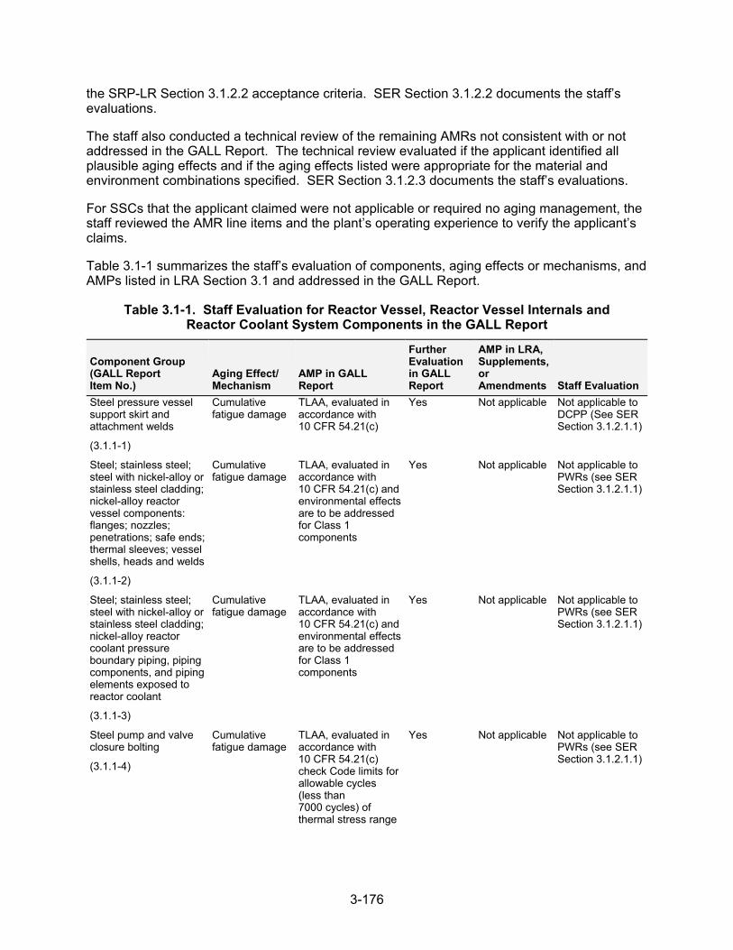
3-176
the SRP-LR Section 3.1.2.2 acceptance criteria. SER Section 3.1.2.2 documents the staff’s evaluations.
The staff also conducted a technical review of the remaining AMRs not consistent with or not addressed in the GALL Report. The technical review evaluated if the applicant identified all plausible aging effects and if the aging effects listed were appropriate for the material and environment combinations specified. SER Section 3.1.2.3 documents the staff’s evaluations.
For SSCs that the applicant claimed were not applicable or required no aging management, the staff reviewed the AMR line items and the plant’s operating experience to verify the applicant’s claims.
Table 3.1-1 summarizes the staff’s evaluation of components, aging effects or mechanisms, and AMPs listed in LRA Section 3.1 and addressed in the GALL Report.
Table 3.1-1. Staff Evaluation for Reactor Vessel, Reactor Vessel Internals and Reactor Coolant System Components in the GALL Report
Component Group (GALL Report Item No.)
Aging Effect/ Mechanism
AMP in GALL Report
Further Evaluation in GALL Report
AMP in LRA, Supplements, or Amendments Staff Evaluation
Steel pressure vessel support skirt and attachment welds
(3.1.1-1)
Cumulative fatigue damage
TLAA, evaluated in accordance with 10 CFR 54.21(c)
Yes Not applicable Not applicable to DCPP (See SER Section 3.1.2.1.1)
Steel; stainless steel; steel with nickel-alloy or stainless steel cladding; nickel-alloy reactor vessel components: flanges; nozzles; penetrations; safe ends; thermal sleeves; vessel shells, heads and welds
(3.1.1-2)
Cumulative fatigue damage
TLAA, evaluated in accordance with 10 CFR 54.21(c) and environmental effects are to be addressed for Class 1 components
Yes Not applicable Not applicable to PWRs (see SER Section 3.1.2.1.1)
Steel; stainless steel; steel with nickel-alloy or stainless steel cladding; nickel-alloy reactor coolant pressure boundary piping, piping components, and piping elements exposed to reactor coolant
(3.1.1-3)
Cumulative fatigue damage
TLAA, evaluated in accordance with 10 CFR 54.21(c) and environmental effects are to be addressed for Class 1 components
Yes Not applicable Not applicable to PWRs (see SER Section 3.1.2.1.1)
Steel pump and valve closure bolting
(3.1.1-4)
Cumulative fatigue damage
TLAA, evaluated in accordance with 10 CFR 54.21(c) check Code limits for allowable cycles (less than 7000 cycles) of thermal stress range
Yes Not applicable Not applicable to PWRs (see SER Section 3.1.2.1.1)
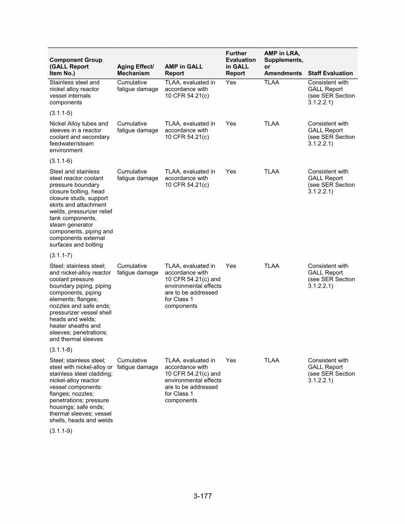
3-177
Component Group (GALL Report Item No.)
Aging Effect/ Mechanism
AMP in GALL Report
Further Evaluation in GALL Report
AMP in LRA, Supplements, or Amendments Staff Evaluation
Stainless steel and nickel alloy reactor vessel internals components
(3.1.1-5)
Cumulative fatigue damage
TLAA, evaluated in accordance with 10 CFR 54.21(c)
Yes TLAA Consistent with GALL Report (see SER Section 3.1.2.2.1)
Nickel Alloy tubes and sleeves in a reactor coolant and secondary feedwater/steam environment
(3.1.1-6)
Cumulative fatigue damage
TLAA, evaluated in accordance with 10 CFR 54.21(c)
Yes TLAA Consistent with GALL Report (see SER Section 3.1.2.2.1)
Steel and stainless steel reactor coolant pressure boundary closure bolting, head closure studs, support skirts and attachment welds, pressurizer relief tank components, steam generator components, piping and components external surfaces and bolting
(3.1.1-7)
Cumulative fatigue damage
TLAA, evaluated in accordance with 10 CFR 54.21(c)
Yes TLAA Consistent with GALL Report (see SER Section 3.1.2.2.1)
Steel; stainless steel; and nickel-alloy reactor coolant pressure boundary piping, piping components, piping elements; flanges; nozzles and safe ends; pressurizer vessel shell heads and welds; heater sheaths and sleeves; penetrations; and thermal sleeves
(3.1.1-8)
Cumulative fatigue damage
TLAA, evaluated in accordance with 10 CFR 54.21(c) and environmental effects are to be addressed for Class 1 components
Yes TLAA Consistent with GALL Report (see SER Section 3.1.2.2.1)
Steel; stainless steel; steel with nickel-alloy or stainless steel cladding; nickel-alloy reactor vessel components: flanges; nozzles; penetrations; pressure housings; safe ends; thermal sleeves; vessel shells, heads and welds
(3.1.1-9)
Cumulative fatigue damage
TLAA, evaluated in accordance with 10 CFR 54.21(c) and environmental effects are to be addressed for Class 1 components
Yes TLAA Consistent with GALL Report (see SER Section 3.1.2.2.1)
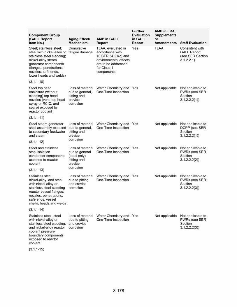
3-178
Component Group (GALL Report Item No.)
Aging Effect/ Mechanism
AMP in GALL Report
Further Evaluation in GALL Report
AMP in LRA, Supplements, or Amendments Staff Evaluation
Steel; stainless steel; steel with nickel-alloy or stainless steel cladding; nickel-alloy steam generator components (flanges; penetrations; nozzles; safe ends, lower heads and welds)
(3.1.1-10)
Cumulative fatigue damage
TLAA, evaluated in accordance with 10 CFR 54.21(c) and environmental effects are to be addressed for Class 1 components
Yes TLAA Consistent with GALL Report (see SER Section 3.1.2.2.1)
Steel top head enclosure (without cladding) top head nozzles (vent, top head spray or RCIC, and spare) exposed to reactor coolant
(3.1.1-11)
Loss of material due to general, pitting and crevice corrosion
Water Chemistry and One-Time Inspection
Yes Not applicable Not applicable to PWRs (see SER Section 3.1.2.2.2(1))
Steel steam generator shell assembly exposed to secondary feedwater and steam
(3.1.1-12)
Loss of material due to general, pitting and crevice corrosion
Water Chemistry and One-Time Inspection
Yes Not applicable Not applicable to DCPP (see SER Section 3.1.2.2.2(1))
Steel and stainless steel isolation condenser components exposed to reactor coolant
(3.1.1-13)
Loss of material due to general (steel only), pitting and crevice corrosion
Water Chemistry and One-Time Inspection
Yes Not applicable Not applicable to PWRs (see SER Section 3.1.2.2.2(2))
Stainless steel, nickel-alloy, and steel with nickel-alloy or stainless steel cladding reactor vessel flanges, nozzles, penetrations, safe ends, vessel shells, heads and welds
(3.1.1-14)
Loss of material due to pitting and crevice corrosion
Water Chemistry and One-Time Inspection
Yes Not applicable Not applicable to PWRs (see SER Section 3.1.2.2.2(3))
Stainless steel; steel with nickel-alloy or stainless steel cladding; and nickel-alloy reactor coolant pressure boundary components exposed to reactor coolant
(3.1.1-15)
Loss of material due to pitting and crevice corrosion
Water Chemistry and One-Time Inspection
Yes Not applicable Not applicable to PWRs (see SER Section 3.1.2.2.2(3))
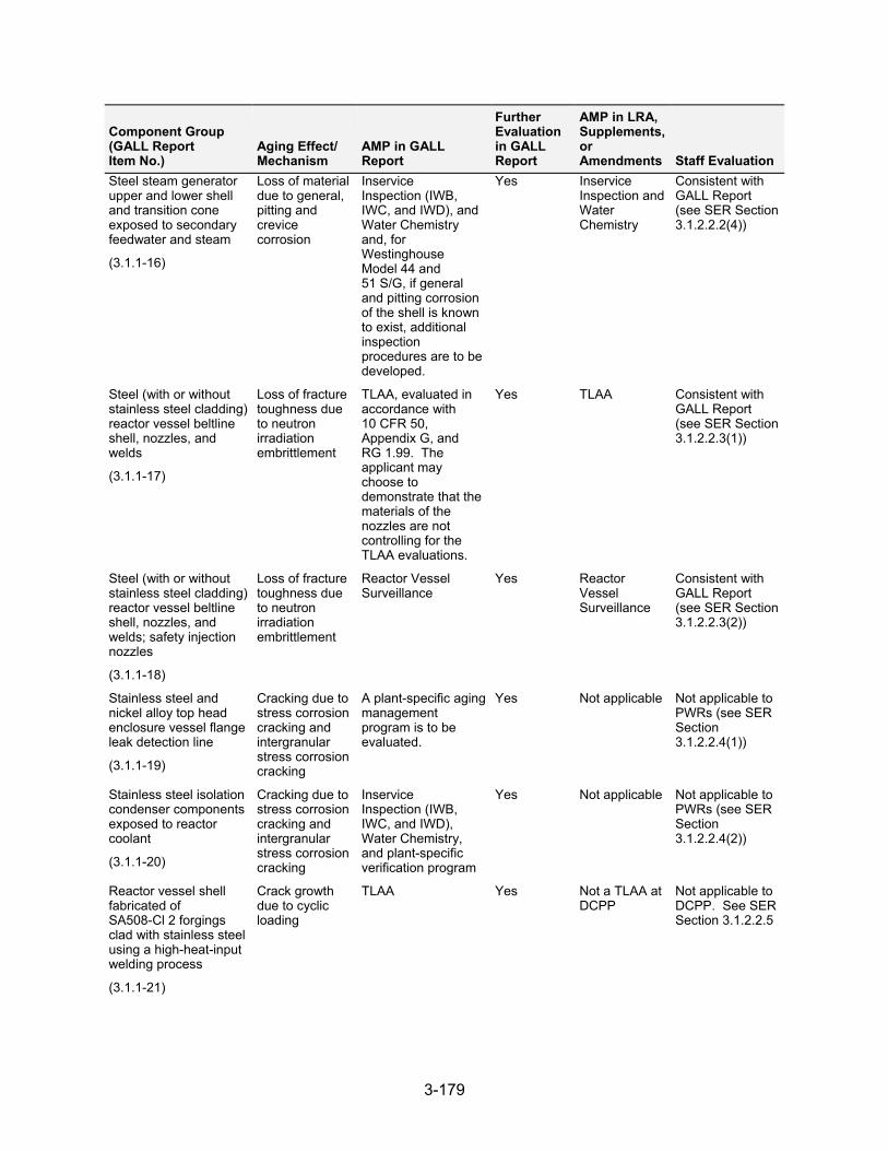
3-179
Component Group (GALL Report Item No.)
Aging Effect/ Mechanism
AMP in GALL Report
Further Evaluation in GALL Report
AMP in LRA, Supplements, or Amendments Staff Evaluation
Steel steam generator upper and lower shell and transition cone exposed to secondary feedwater and steam
(3.1.1-16)
Loss of material due to general, pitting and crevice corrosion
Inservice Inspection (IWB, IWC, and IWD), and Water Chemistry and, for Westinghouse Model 44 and 51 S/G, if general and pitting corrosion of the shell is known to exist, additional inspection procedures are to be developed.
Yes Inservice Inspection and Water Chemistry
Consistent with GALL Report (see SER Section 3.1.2.2.2(4))
Steel (with or without stainless steel cladding) reactor vessel beltline shell, nozzles, and welds
(3.1.1-17)
Loss of fracture toughness due to neutron irradiation embrittlement
TLAA, evaluated in accordance with 10 CFR 50, Appendix G, and RG 1.99. The applicant may choose to demonstrate that the materials of the nozzles are not controlling for the TLAA evaluations.
Yes TLAA Consistent with GALL Report (see SER Section 3.1.2.2.3(1))
Steel (with or without stainless steel cladding) reactor vessel beltline shell, nozzles, and welds; safety injection nozzles
(3.1.1-18)
Loss of fracture toughness due to neutron irradiation embrittlement
Reactor Vessel Surveillance
Yes Reactor Vessel Surveillance
Consistent with GALL Report (see SER Section 3.1.2.2.3(2))
Stainless steel and nickel alloy top head enclosure vessel flange leak detection line
(3.1.1-19)
Cracking due to stress corrosion cracking and intergranular stress corrosion cracking
A plant-specific aging management program is to be evaluated.
Yes Not applicable Not applicable to PWRs (see SER Section 3.1.2.2.4(1))
Stainless steel isolation condenser components exposed to reactor coolant
(3.1.1-20)
Cracking due to stress corrosion cracking and intergranular stress corrosion cracking
Inservice Inspection (IWB, IWC, and IWD), Water Chemistry, and plant-specific verification program
Yes Not applicable Not applicable to PWRs (see SER Section 3.1.2.2.4(2))
Reactor vessel shell fabricated of SA508-Cl 2 forgings clad with stainless steel using a high-heat-input welding process
(3.1.1-21)
Crack growth due to cyclic loading
TLAA Yes Not a TLAA at DCPP
Not applicable to DCPP. See SER Section 3.1.2.2.5
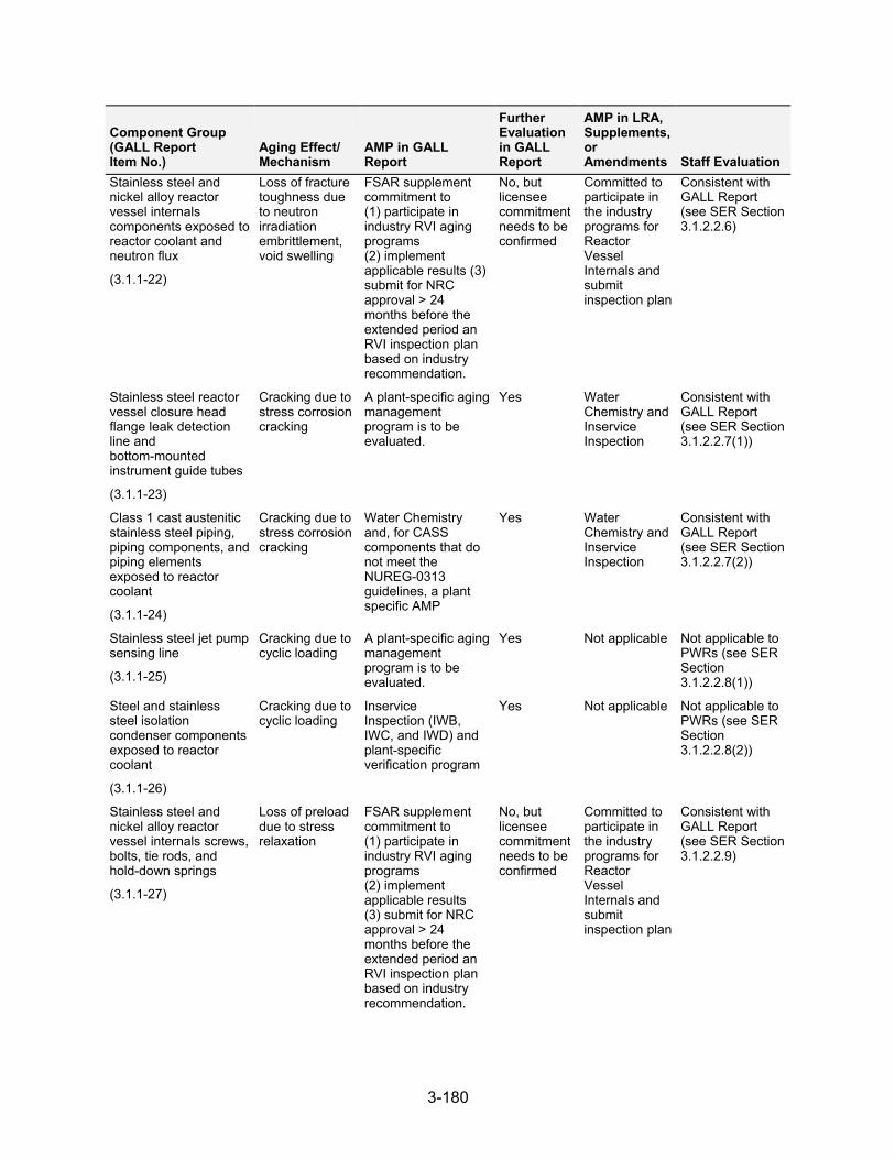
3-180
Component Group (GALL Report Item No.)
Aging Effect/ Mechanism
AMP in GALL Report
Further Evaluation in GALL Report
AMP in LRA, Supplements, or Amendments Staff Evaluation
Stainless steel and nickel alloy reactor vessel internals components exposed to reactor coolant and neutron flux
(3.1.1-22)
Loss of fracture toughness due to neutron irradiation embrittlement, void swelling
FSAR supplement commitment to (1) participate in industry RVI aging programs (2) implement applicable results (3) submit for NRC approval > 24 months before the extended period an RVI inspection plan based on industry recommendation.
No, but licensee commitment needs to be confirmed
Committed to participate in the industry programs for Reactor Vessel Internals and submit inspection plan
Consistent with GALL Report (see SER Section 3.1.2.2.6)
Stainless steel reactor vessel closure head flange leak detection line and bottom-mounted instrument guide tubes
(3.1.1-23)
Cracking due to stress corrosion cracking
A plant-specific aging management program is to be evaluated.
Yes Water Chemistry and Inservice Inspection
Consistent with GALL Report (see SER Section 3.1.2.2.7(1))
Class 1 cast austenitic stainless steel piping, piping components, and piping elements exposed to reactor coolant
(3.1.1-24)
Cracking due to stress corrosion cracking
Water Chemistry and, for CASS components that do not meet the NUREG-0313 guidelines, a plant specific AMP
Yes Water Chemistry and Inservice Inspection
Consistent with GALL Report (see SER Section 3.1.2.2.7(2))
Stainless steel jet pump sensing line
(3.1.1-25)
Cracking due to cyclic loading
A plant-specific aging management program is to be evaluated.
Yes Not applicable Not applicable to PWRs (see SER Section 3.1.2.2.8(1))
Steel and stainless steel isolation condenser components exposed to reactor coolant
(3.1.1-26)
Cracking due to cyclic loading
Inservice Inspection (IWB, IWC, and IWD) and plant-specific verification program
Yes Not applicable Not applicable to PWRs (see SER Section 3.1.2.2.8(2))
Stainless steel and nickel alloy reactor vessel internals screws, bolts, tie rods, and hold-down springs
(3.1.1-27)
Loss of preload due to stress relaxation
FSAR supplement commitment to (1) participate in industry RVI aging programs (2) implement applicable results (3) submit for NRC approval > 24 months before the extended period an RVI inspection plan based on industry recommendation.
No, but licensee commitment needs to be confirmed
Committed to participate in the industry programs for Reactor Vessel Internals and submit inspection plan
Consistent with GALL Report (see SER Section 3.1.2.2.9)
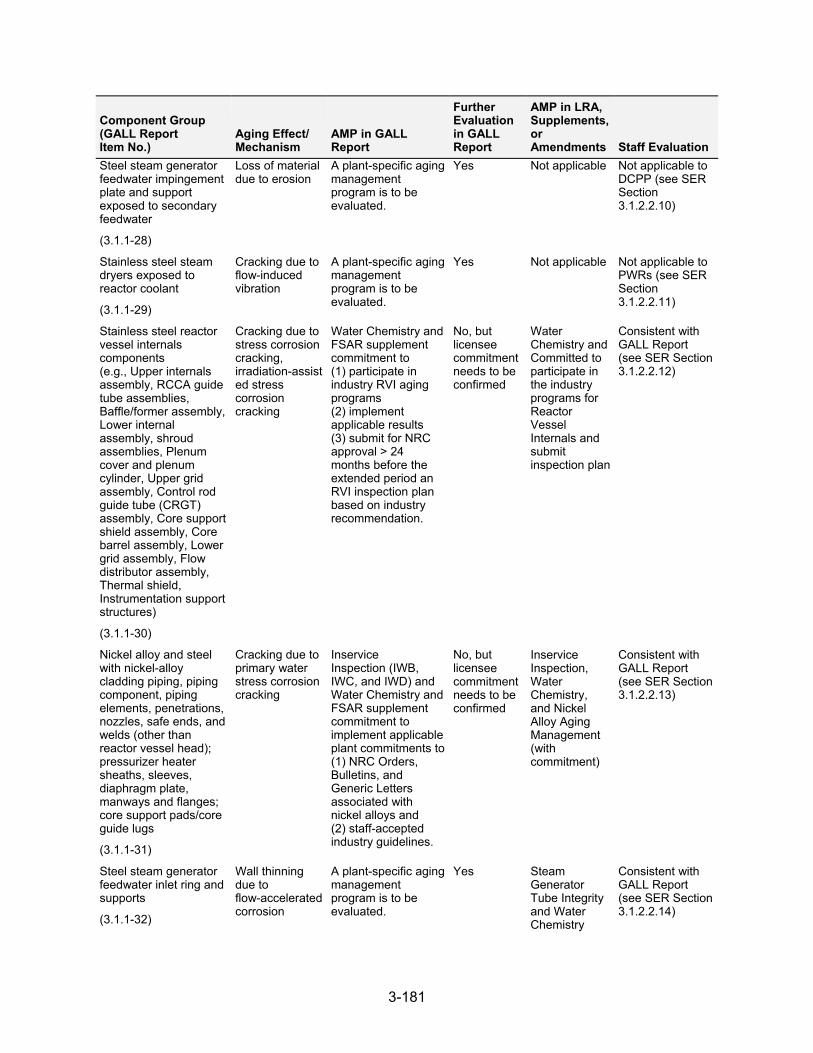
3-181
Component Group (GALL Report Item No.)
Aging Effect/ Mechanism
AMP in GALL Report
Further Evaluation in GALL Report
AMP in LRA, Supplements, or Amendments Staff Evaluation
Steel steam generator feedwater impingement plate and support exposed to secondary feedwater
(3.1.1-28)
Loss of material due to erosion
A plant-specific aging management program is to be evaluated.
Yes Not applicable Not applicable to DCPP (see SER Section 3.1.2.2.10)
Stainless steel steam dryers exposed to reactor coolant
(3.1.1-29)
Cracking due to flow-induced vibration
A plant-specific aging management program is to be evaluated.
Yes Not applicable Not applicable toPWRs (see SER Section 3.1.2.2.11)
Stainless steel reactor vessel internals components (e.g., Upper internals assembly, RCCA guide tube assemblies, Baffle/former assembly, Lower internal assembly, shroud assemblies, Plenum cover and plenum cylinder, Upper grid assembly, Control rod guide tube (CRGT) assembly, Core support shield assembly, Core barrel assembly, Lower grid assembly, Flow distributor assembly, Thermal shield, Instrumentation support structures)
(3.1.1-30)
Cracking due to stress corrosion cracking, irradiation-assisted stress corrosion cracking
Water Chemistry and FSAR supplement commitment to (1) participate in industry RVI aging programs (2) implement applicable results (3) submit for NRC approval > 24 months before the extended period an RVI inspection plan based on industry recommendation.
No, but licensee commitment needs to be confirmed
Water Chemistry and Committed to participate in the industry programs for Reactor Vessel Internals and submit inspection plan
Consistent with GALL Report (see SER Section 3.1.2.2.12)
Nickel alloy and steel with nickel-alloy cladding piping, piping component, piping elements, penetrations, nozzles, safe ends, and welds (other than reactor vessel head); pressurizer heater sheaths, sleeves, diaphragm plate, manways and flanges; core support pads/core guide lugs
(3.1.1-31)
Cracking due to primary water stress corrosion cracking
Inservice Inspection (IWB, IWC, and IWD) and Water Chemistry and FSAR supplement commitment to implement applicable plant commitments to (1) NRC Orders, Bulletins, and Generic Letters associated with nickel alloys and (2) staff-accepted industry guidelines.
No, but licensee commitment needs to be confirmed
Inservice Inspection, Water Chemistry, and Nickel Alloy Aging Management (with commitment)
Consistent with GALL Report (see SER Section 3.1.2.2.13)
Steel steam generator feedwater inlet ring and supports
(3.1.1-32)
Wall thinning due to flow-accelerated corrosion
A plant-specific aging management program is to be evaluated.
Yes Steam Generator Tube Integrity and Water Chemistry
Consistent with GALL Report (see SER Section 3.1.2.2.14)
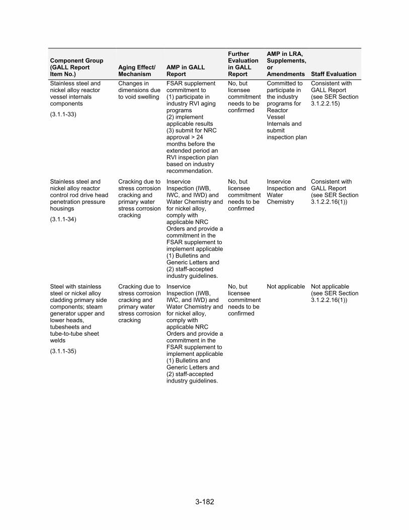
3-182
Component Group (GALL Report Item No.)
Aging Effect/ Mechanism
AMP in GALL Report
Further Evaluation in GALL Report
AMP in LRA, Supplements, or Amendments Staff Evaluation
Stainless steel and nickel alloy reactor vessel internals components
(3.1.1-33)
Changes in dimensions due to void swelling
FSAR supplement commitment to (1) participate in industry RVI aging programs (2) implement applicable results (3) submit for NRC approval > 24 months before the extended period an RVI inspection plan based on industry recommendation.
No, but licensee commitment needs to be confirmed
Committed to participate in the industry programs for Reactor Vessel Internals and submit inspection plan
Consistent with GALL Report (see SER Section 3.1.2.2.15)
Stainless steel and nickel alloy reactor control rod drive head penetration pressure housings
(3.1.1-34)
Cracking due to stress corrosion cracking and primary water stress corrosion cracking
Inservice Inspection (IWB, IWC, and IWD) and Water Chemistry and for nickel alloy, comply with applicable NRC Orders and provide a commitment in the FSAR supplement to implement applicable (1) Bulletins and Generic Letters and (2) staff-accepted industry guidelines.
No, but licensee commitment needs to be confirmed
Inservice Inspection and Water Chemistry
Consistent with GALL Report (see SER Section 3.1.2.2.16(1))
Steel with stainless steel or nickel alloy cladding primary side components; steam generator upper and lower heads, tubesheets and tube-to-tube sheet welds
(3.1.1-35)
Cracking due to stress corrosion cracking and primary water stress corrosion cracking
Inservice Inspection (IWB, IWC, and IWD) and Water Chemistry and for nickel alloy, comply with applicable NRC Orders and provide a commitment in the FSAR supplement to implement applicable (1) Bulletins and Generic Letters and (2) staff-accepted industry guidelines.
No, but licensee commitment needs to be confirmed
Not applicable Not applicable (see SER Section 3.1.2.2.16(1))
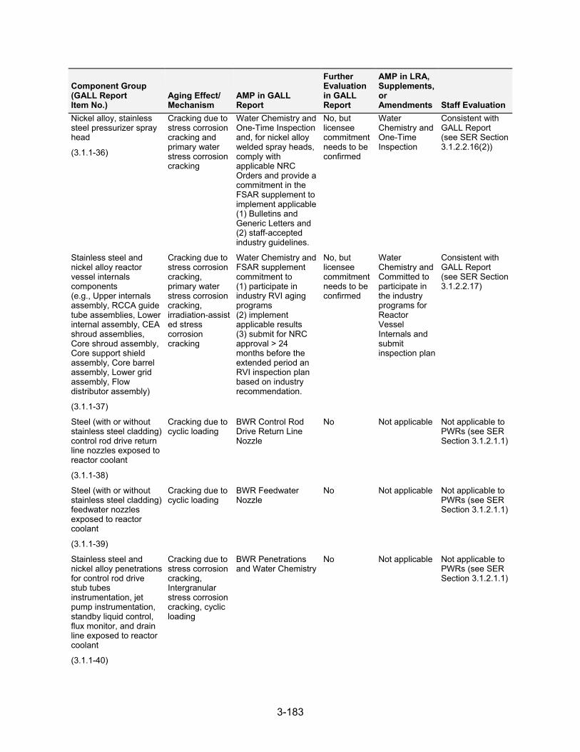
3-183
Component Group (GALL Report Item No.)
Aging Effect/ Mechanism
AMP in GALL Report
Further Evaluation in GALL Report
AMP in LRA, Supplements, or Amendments Staff Evaluation
Nickel alloy, stainless steel pressurizer spray head
(3.1.1-36)
Cracking due to stress corrosion cracking and primary water stress corrosion cracking
Water Chemistry and One-Time Inspection and, for nickel alloy welded spray heads, comply with applicable NRC Orders and provide a commitment in the FSAR supplement to implement applicable (1) Bulletins and Generic Letters and (2) staff-accepted industry guidelines.
No, but licensee commitment needs to be confirmed
Water Chemistry and One-Time Inspection
Consistent with GALL Report (see SER Section 3.1.2.2.16(2))
Stainless steel and nickel alloy reactor vessel internals components (e.g., Upper internals assembly, RCCA guide tube assemblies, Lower internal assembly, CEA shroud assemblies, Core shroud assembly, Core support shield assembly, Core barrel assembly, Lower grid assembly, Flow distributor assembly)
(3.1.1-37)
Cracking due to stress corrosion cracking, primary water stress corrosion cracking, irradiation-assisted stress corrosion cracking
Water Chemistry and FSAR supplement commitment to (1) participate in industry RVI aging programs (2) implement applicable results (3) submit for NRC approval > 24 months before the extended period an RVI inspection plan based on industry recommendation.
No, but licensee commitment needs to be confirmed
Water Chemistry and Committed to participate in the industry programs for Reactor Vessel Internals and submit inspection plan
Consistent with GALL Report (see SER Section 3.1.2.2.17)
Steel (with or without stainless steel cladding) control rod drive return line nozzles exposed to reactor coolant
(3.1.1-38)
Cracking due to cyclic loading
BWR Control Rod Drive Return Line Nozzle
No Not applicable Not applicable toPWRs (see SER Section 3.1.2.1.1)
Steel (with or without stainless steel cladding) feedwater nozzles exposed to reactor coolant
(3.1.1-39)
Cracking due to cyclic loading
BWR Feedwater Nozzle
No Not applicable Not applicable to PWRs (see SER Section 3.1.2.1.1)
Stainless steel and nickel alloy penetrations for control rod drive stub tubes instrumentation, jet pump instrumentation, standby liquid control, flux monitor, and drain line exposed to reactor coolant
(3.1.1-40)
Cracking due to stress corrosion cracking, Intergranular stress corrosion cracking, cyclic loading
BWR Penetrations and Water Chemistry
No Not applicable Not applicable to PWRs (see SER Section 3.1.2.1.1)
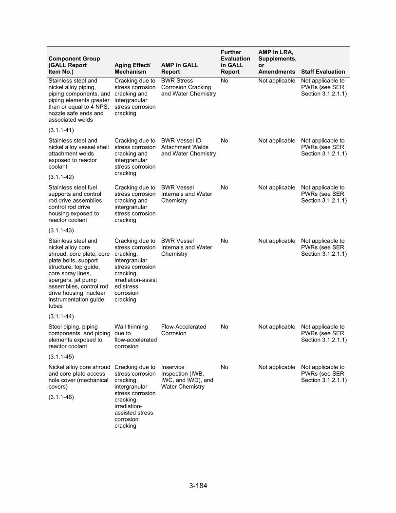
3-184
Component Group (GALL Report Item No.)
Aging Effect/ Mechanism
AMP in GALL Report
Further Evaluation in GALL Report
AMP in LRA, Supplements, or Amendments Staff Evaluation
Stainless steel and nickel alloy piping, piping components, and piping elements greater than or equal to 4 NPS; nozzle safe ends and associated welds
(3.1.1-41)
Cracking due to stress corrosion cracking and intergranular stress corrosion cracking
BWR Stress Corrosion Cracking and Water Chemistry
No Not applicable Not applicable to PWRs (see SER Section 3.1.2.1.1)
Stainless steel and nickel alloy vessel shell attachment welds exposed to reactor coolant
(3.1.1-42)
Cracking due to stress corrosion cracking and intergranular stress corrosion cracking
BWR Vessel ID Attachment Welds and Water Chemistry
No Not applicable Not applicable to PWRs (see SER Section 3.1.2.1.1)
Stainless steel fuel supports and control rod drive assemblies control rod drive housing exposed to reactor coolant
(3.1.1-43)
Cracking due to stress corrosion cracking and intergranular stress corrosion cracking
BWR Vessel Internals and Water Chemistry
No Not applicable Not applicable to PWRs (see SER Section 3.1.2.1.1)
Stainless steel and nickel alloy core shroud, core plate, core plate bolts, support structure, top guide, core spray lines, spargers, jet pump assemblies, control rod drive housing, nuclear instrumentation guide tubes
(3.1.1-44)
Cracking due to stress corrosion cracking, intergranular stress corrosion cracking, irradiation-assisted stress corrosion cracking
BWR Vessel Internals and Water Chemistry
No Not applicable Not applicable to PWRs (see SER Section 3.1.2.1.1)
Steel piping, piping components, and piping elements exposed to reactor coolant
(3.1.1-45)
Wall thinning due to flow-accelerated corrosion
Flow-Accelerated Corrosion
No Not applicable Not applicable to PWRs (see SER Section 3.1.2.1.1)
Nickel alloy core shroud and core plate access hole cover (mechanical covers)
(3.1.1-46)
Cracking due to stress corrosion cracking, intergranular stress corrosion cracking, irradiation- assisted stress corrosion cracking
Inservice Inspection (IWB, IWC, and IWD), and Water Chemistry
No Not applicable Not applicable to PWRs (see SER Section 3.1.2.1.1)
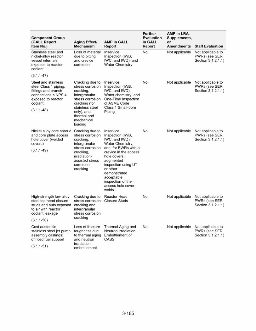
3-185
Component Group (GALL Report Item No.)
Aging Effect/ Mechanism
AMP in GALL Report
Further Evaluation in GALL Report
AMP in LRA, Supplements, or Amendments Staff Evaluation
Stainless steel and nickel-alloy reactor vessel internals exposed to reactor coolant
(3.1.1-47)
Loss of material due to pitting and crevice corrosion
Inservice Inspection (IWB, IWC, and IWD), and Water Chemistry
No Not applicable Not applicable to PWRs (see SER Section 3.1.2.1.1)
Steel and stainless steel Class 1 piping, fittings and branch connections < NPS 4 exposed to reactor coolant
(3.1.1-48)
Cracking due to stress corrosion cracking, intergranular stress corrosion cracking (for stainless steel only), and thermal and mechanical loading
Inservice Inspection (IWB, IWC, and IWD), Water chemistry, and One-Time Inspection of ASME Code Class 1 Small-bore Piping
No Not applicable Not applicable to PWRs (see SER Section 3.1.2.1.1)
Nickel alloy core shroud and core plate access hole cover (welded covers)
(3.1.1-49)
Cracking due to stress corrosion cracking, intergranular stress corrosion cracking, irradiation- assisted stress corrosion cracking
Inservice Inspection (IWB, IWC, and IWD), Water Chemistry, and, for BWRs with a crevice in the access hole covers, augmented inspection using UT or other demonstrated acceptable inspection of the access hole cover welds
No Not applicable Not applicable to PWRs (see SER Section 3.1.2.1.1)
High-strength low alloy steel top head closure studs and nuts exposed to air with reactor coolant leakage
(3.1.1-50)
Cracking due to stress corrosion cracking and intergranular stress corrosion cracking
Reactor Head Closure Studs
No Not applicable Not applicable to PWRs (see SER Section 3.1.2.1.1)
Cast austenitic stainless steel jet pump assembly castings; orificed fuel support
(3.1.1-51)
Loss of fracture toughness due to thermal aging and neutron irradiation embrittlement
Thermal Aging and Neutron Irradiation Embrittlement of CASS
No Not applicable Not applicable to PWRs (see SER Section 3.1.2.1.1)
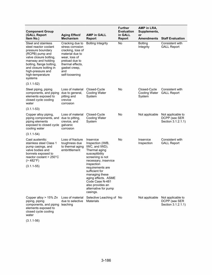
3-186
Component Group (GALL Report Item No.)
Aging Effect/ Mechanism
AMP in GALL Report
Further Evaluation in GALL Report
AMP in LRA, Supplements, or Amendments Staff Evaluation
Steel and stainless steel reactor coolant pressure boundary (RCPB) pump and valve closure bolting, manway and holding bolting, flange bolting, and closure bolting in high-pressure and high-temperature systems
(3.1.1-52)
Cracking due to stress corrosion cracking, loss of material due to wear, loss of preload due to thermal effects, gasket creep, and self-loosening
Bolting Integrity No Bolting Integrity
Consistent with GALL Report
Steel piping, piping components, and piping elements exposed to closed cycle cooling water
(3.1.1-53)
Loss of material due to general, pitting and crevice corrosion
Closed-Cycle Cooling Water System
No Closed-Cycle Cooling Water System
Consistent with GALL Report
Copper alloy piping, piping components, and piping elements exposed to closed cycle cooling water
(3.1.1-54)
Loss of material due to pitting, crevice, and galvanic corrosion
Closed-Cycle Cooling Water System
No Not applicable Not applicable to DCPP (see SER Section 3.1.2.1.1)
Cast austenitic stainless steel Class 1 pump casings, and valve bodies and bonnets exposed to reactor coolant > 250°C (> 482°F)
(3.1.1-55)
Loss of fracture toughness due to thermal aging embrittlement
Inservice Inspection (IWB, IWC, and IWD). Thermal aging susceptibility screening is not necessary, inservice inspection requirements are sufficient for managing these aging effects. ASME Code Case N-481 also provides an alternative for pump casings.
No Inservice Inspection
Consistent with GALL Report
Copper alloy > 15% Zn piping, piping components, and piping elements exposed to closed cycle cooling water
(3.1.1-56)
Loss of material due to selective leaching
Selective Leaching of Materials
No Not applicable Not applicable to DCPP (see SER Section 3.1.2.1.1)
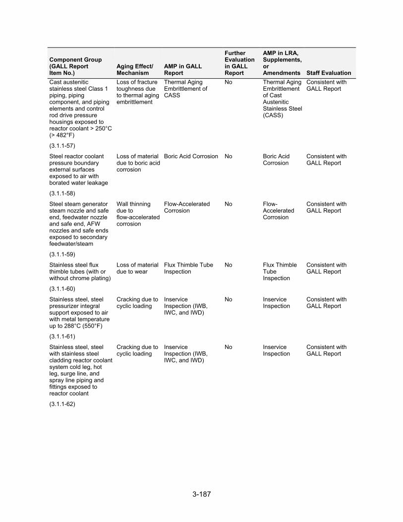
3-187
Component Group (GALL Report Item No.)
Aging Effect/ Mechanism
AMP in GALL Report
Further Evaluation in GALL Report
AMP in LRA, Supplements, or Amendments Staff Evaluation
Cast austenitic stainless steel Class 1 piping, piping component, and piping elements and control rod drive pressure housings exposed to reactor coolant > 250°C (> 482°F)
(3.1.1-57)
Loss of fracture toughness due to thermal aging embrittlement
Thermal Aging Embrittlement of CASS
No Thermal Aging Embrittlement of Cast Austenitic Stainless Steel (CASS)
Consistent with GALL Report
Steel reactor coolant pressure boundary external surfaces exposed to air with borated water leakage
(3.1.1-58)
Loss of material due to boric acid corrosion
Boric Acid Corrosion No Boric Acid Corrosion
Consistent with GALL Report
Steel steam generator steam nozzle and safe end, feedwater nozzle and safe end, AFW nozzles and safe ends exposed to secondary feedwater/steam
(3.1.1-59)
Wall thinning due to flow-accelerated corrosion
Flow-Accelerated Corrosion
No Flow-Accelerated Corrosion
Consistent with GALL Report
Stainless steel flux thimble tubes (with or without chrome plating)
(3.1.1-60)
Loss of material due to wear
Flux Thimble Tube Inspection
No Flux Thimble Tube Inspection
Consistent with GALL Report
Stainless steel, steel pressurizer integral support exposed to air with metal temperature up to 288°C (550°F)
(3.1.1-61)
Cracking due to cyclic loading
Inservice Inspection (IWB, IWC, and IWD)
No Inservice Inspection
Consistent with GALL Report
Stainless steel, steel with stainless steel cladding reactor coolant system cold leg, hot leg, surge line, and spray line piping and fittings exposed to reactor coolant
(3.1.1-62)
Cracking due to cyclic loading
Inservice Inspection (IWB, IWC, and IWD)
No Inservice Inspection
Consistent with GALL Report
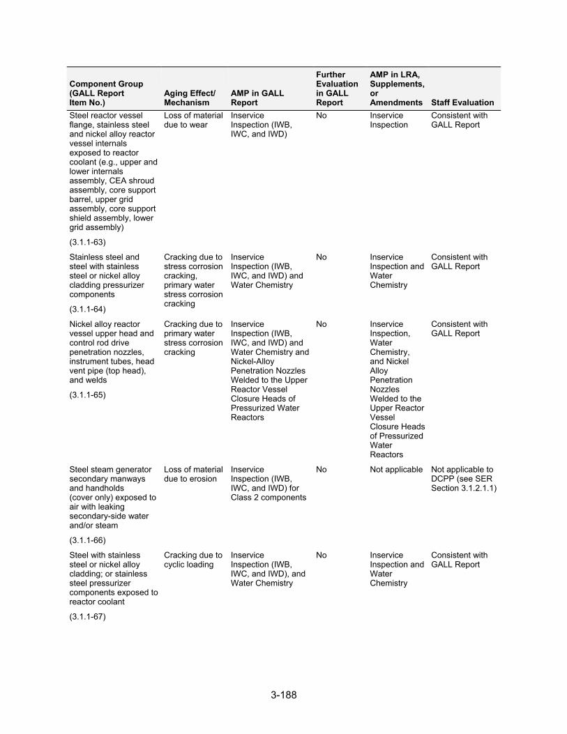
3-188
Component Group (GALL Report Item No.)
Aging Effect/ Mechanism
AMP in GALL Report
Further Evaluation in GALL Report
AMP in LRA, Supplements, or Amendments Staff Evaluation
Steel reactor vessel flange, stainless steel and nickel alloy reactor vessel internals exposed to reactor coolant (e.g., upper and lower internals assembly, CEA shroud assembly, core support barrel, upper grid assembly, core support shield assembly, lower grid assembly)
(3.1.1-63)
Loss of material due to wear
Inservice Inspection (IWB, IWC, and IWD)
No Inservice Inspection
Consistent with GALL Report
Stainless steel and steel with stainless steel or nickel alloy cladding pressurizer components
(3.1.1-64)
Cracking due to stress corrosion cracking, primary water stress corrosion cracking
Inservice Inspection (IWB, IWC, and IWD) and Water Chemistry
No Inservice Inspection and Water Chemistry
Consistent with GALL Report
Nickel alloy reactor vessel upper head and control rod drive penetration nozzles, instrument tubes, head vent pipe (top head), and welds
(3.1.1-65)
Cracking due to primary water stress corrosion cracking
Inservice Inspection (IWB, IWC, and IWD) and Water Chemistry and Nickel-Alloy Penetration Nozzles Welded to the Upper Reactor Vessel Closure Heads of Pressurized Water Reactors
No Inservice Inspection, Water Chemistry, and Nickel Alloy Penetration Nozzles Welded to the Upper Reactor Vessel Closure Heads of Pressurized Water Reactors
Consistent with GALL Report
Steel steam generator secondary manways and handholds (cover only) exposed to air with leaking secondary-side water and/or steam
(3.1.1-66)
Loss of material due to erosion
Inservice Inspection (IWB, IWC, and IWD) for Class 2 components
No Not applicable Not applicable to DCPP (see SER Section 3.1.2.1.1)
Steel with stainless steel or nickel alloy cladding; or stainless steel pressurizer components exposed to reactor coolant
(3.1.1-67)
Cracking due to cyclic loading
Inservice Inspection (IWB, IWC, and IWD), and Water Chemistry
No Inservice Inspection and Water Chemistry
Consistent with GALL Report
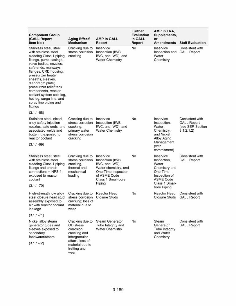
3-189
Component Group (GALL Report Item No.)
Aging Effect/ Mechanism
AMP in GALL Report
Further Evaluation in GALL Report
AMP in LRA, Supplements, or Amendments Staff Evaluation
Stainless steel, steel with stainless steel cladding Class 1 piping, fittings, pump casings, valve bodies, nozzles, safe ends, manways, flanges, CRD housing; pressurizer heater sheaths, sleeves, diaphragm plate; pressurizer relief tank components, reactor coolant system cold leg, hot leg, surge line, and spray line piping and fittings
(3.1.1-68)
Cracking due to stress corrosion cracking
Inservice Inspection (IWB, IWC, and IWD), and Water Chemistry
No Inservice Inspection and Water Chemistry
Consistent with GALL Report
Stainless steel, nickel alloy safety injection nozzles, safe ends, and associated welds and buttering exposed to reactor coolant
(3.1.1-69)
Cracking due to stress corrosion cracking, primary water stress corrosion cracking
Inservice Inspection (IWB, IWC, and IWD), and Water Chemistry
No Inservice Inspection, Water Chemistry, and Nickel Alloy Aging Management (with commitment)
Consistent with GALL Report (see SER Section 3.1.2.1.2)
Stainless steel; steel with stainless steel cladding Class 1 piping, fittings and branch connections < NPS 4 exposed to reactor coolant
(3.1.1-70)
Cracking due to stress corrosion cracking, thermal and mechanical loading
Inservice Inspection (IWB, IWC, and IWD), Water chemistry, and One-Time Inspection of ASME Code Class 1 Small-bore Piping
No Inservice Inspection, Water Chemistry and One-Time Inspection of ASME Code Class 1 Small-bore Piping
Consistent with GALL Report
High-strength low alloy steel closure head stud assembly exposed to air with reactor coolant leakage
(3.1.1-71)
Cracking due to stress corrosion cracking; loss of material due to wear
Reactor Head Closure Studs
No Reactor Head Closure Studs
Consistent with GALL Report
Nickel alloy steam generator tubes and sleeves exposed to secondary feedwater/steam
(3.1.1-72)
Cracking due to OD stress corrosion cracking and intergranular attack, loss of material due to fretting and wear
Steam Generator Tube Integrity and Water Chemistry
No Steam Generator Tube Integrity and Water Chemistry
Consistent with GALL Report
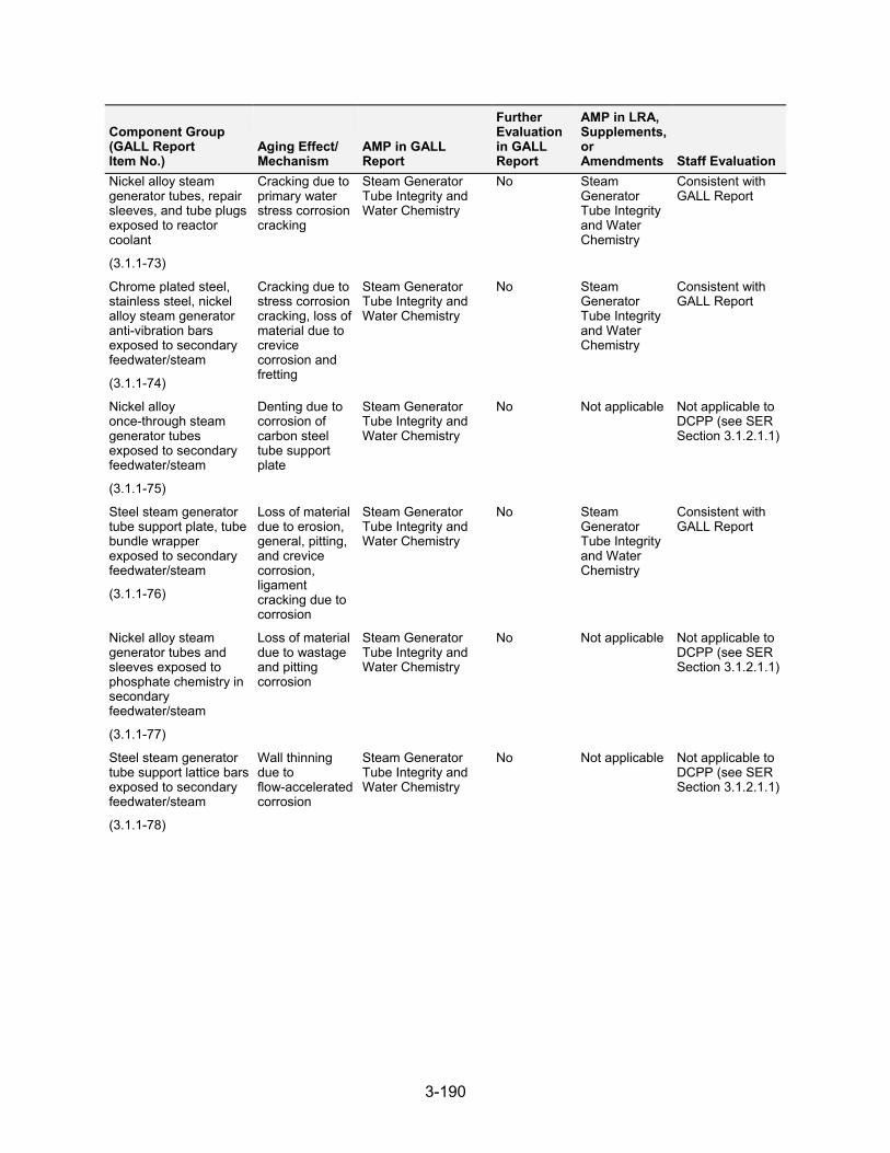
3-190
Component Group (GALL Report Item No.)
Aging Effect/ Mechanism
AMP in GALL Report
Further Evaluation in GALL Report
AMP in LRA, Supplements, or Amendments Staff Evaluation
Nickel alloy steam generator tubes, repair sleeves, and tube plugs exposed to reactor coolant
(3.1.1-73)
Cracking due to primary water stress corrosion cracking
Steam Generator Tube Integrity and Water Chemistry
No Steam Generator Tube Integrity and Water Chemistry
Consistent with GALL Report
Chrome plated steel, stainless steel, nickel alloy steam generator anti-vibration bars exposed to secondary feedwater/steam
(3.1.1-74)
Cracking due to stress corrosion cracking, loss of material due to crevice corrosion and fretting
Steam Generator Tube Integrity and Water Chemistry
No Steam Generator Tube Integrity and Water Chemistry
Consistent with GALL Report
Nickel alloy once-through steam generator tubes exposed to secondary feedwater/steam
(3.1.1-75)
Denting due to corrosion of carbon steel tube support plate
Steam Generator Tube Integrity and Water Chemistry
No Not applicable Not applicable to DCPP (see SER Section 3.1.2.1.1)
Steel steam generator tube support plate, tube bundle wrapper exposed to secondary feedwater/steam
(3.1.1-76)
Loss of material due to erosion, general, pitting, and crevice corrosion, ligament cracking due to corrosion
Steam Generator Tube Integrity and Water Chemistry
No Steam Generator Tube Integrity and Water Chemistry
Consistent with GALL Report
Nickel alloy steam generator tubes and sleeves exposed to phosphate chemistry in secondary feedwater/steam
(3.1.1-77)
Loss of material due to wastage and pitting corrosion
Steam Generator Tube Integrity and Water Chemistry
No Not applicable Not applicable to DCPP (see SER Section 3.1.2.1.1)
Steel steam generator tube support lattice bars exposed to secondary feedwater/steam
(3.1.1-78)
Wall thinning due to flow-accelerated corrosion
Steam Generator Tube Integrity and Water Chemistry
No Not applicable Not applicable to DCPP (see SER Section 3.1.2.1.1)
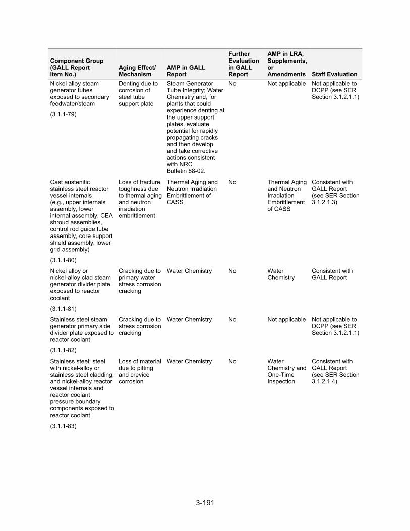
3-191
Component Group (GALL Report Item No.)
Aging Effect/ Mechanism
AMP in GALL Report
Further Evaluation in GALL Report
AMP in LRA, Supplements, or Amendments Staff Evaluation
Nickel alloy steam generator tubes exposed to secondary feedwater/steam
(3.1.1-79)
Denting due to corrosion of steel tube support plate
Steam Generator Tube Integrity; Water Chemistry and, for plants that could experience denting at the upper support plates, evaluate potential for rapidly propagating cracks and then develop and take corrective actions consistent with NRC Bulletin 88-02.
No Not applicable Not applicable to DCPP (see SER Section 3.1.2.1.1)
Cast austenitic stainless steel reactor vessel internals (e.g., upper internals assembly, lower internal assembly, CEA shroud assemblies, control rod guide tube assembly, core support shield assembly, lower grid assembly)
(3.1.1-80)
Loss of fracture toughness due to thermal aging and neutron irradiation embrittlement
Thermal Aging and Neutron Irradiation Embrittlement of CASS
No Thermal Aging and Neutron Irradiation Embrittlement of CASS
Consistent with GALL Report (see SER Section 3.1.2.1.3)
Nickel alloy or nickel-alloy clad steam generator divider plate exposed to reactor coolant
(3.1.1-81)
Cracking due to primary water stress corrosion cracking
Water Chemistry No Water Chemistry
Consistent with GALL Report
Stainless steel steam generator primary side divider plate exposed to reactor coolant
(3.1.1-82)
Cracking due to stress corrosion cracking
Water Chemistry No Not applicable Not applicable to DCPP (see SER Section 3.1.2.1.1)
Stainless steel; steel with nickel-alloy or stainless steel cladding; and nickel-alloy reactor vessel internals and reactor coolant pressure boundary components exposed to reactor coolant
(3.1.1-83)
Loss of material due to pitting and crevice corrosion
Water Chemistry No Water Chemistry and One-Time Inspection
Consistent with GALL Report (see SER Section 3.1.2.1.4)
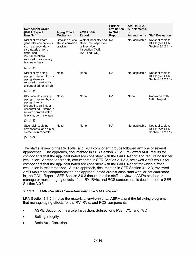
3-192
Component Group (GALL Report Item No.)
Aging Effect/ Mechanism
AMP in GALL Report
Further Evaluation in GALL Report
AMP in LRA, Supplements, or Amendments Staff Evaluation
Nickel alloy steam generator components such as, secondary side nozzles (vent, drain, and instrumentation) exposed to secondary feedwater/steam
(3.1.1-84)
Cracking due to stress corrosion cracking
Water Chemistry and One-Time Inspection or Inservice Inspection (IWB, IWC, and IWD).
No Not applicable Not applicable to DCPP (see SER Section 3.1.2.1.1)
Nickel alloy piping, piping components, and piping elements exposed to air-indoor uncontrolled (external)
(3.1.1-85)
None None NA Not applicable Not applicable to DCPP (see SER Section 3.1.2.1.1)
Stainless steel piping, piping components, and piping elements exposed to air-indoor uncontrolled (External); air with borated water leakage; concrete; gas
(3.1.1-86)
None None NA None Consistent with GALL Report
Steel piping, piping components, and piping elements in concrete
(3.1.1-87)
None None NA Not applicable Not applicable to DCPP (see SER Section 3.1.2.1.1)
The staff’s review of the RV, RVIs, and RCS component groups followed any one of several approaches. One approach, documented in SER Section 3.1.2.1, reviewed AMR results for components that the applicant noted are consistent with the GALL Report and require no further evaluation. Another approach, documented in SER Section 3.1.2.2, reviewed AMR results for components that the applicant noted are consistent with the GALL Report for which further evaluation is recommended. A third approach, documented in SER Section 3.1.2.3, reviewed AMR results for components that the applicant noted are not consistent with, or not addressed in, the GALL Report. SER Section 3.0.3 documents the staff’s review of AMPs credited to manage or monitor aging effects of the RV, RVIs, and RCS components is documented in SER Section 3.0.3.
3.1.2.1 AMR Results Consistent with the GALL Report
LRA Section 3.1.2.1 notes the materials, environments, AERMs, and the following programs that manage aging effects for the RV, RVIs, and RCS components:
ASME Section XI Inservice Inspection, Subsections IWB, IWC, and IWD
Bolting Integrity
Boric Acid Corrosion
3-193
Closed-Cycle Cooling Water System
External Surfaces Monitoring Program
Inspection of Internal Surfaces in Miscellaneous Piping and Ducting Components
Flow-Accelerated Corrosion
Flux Thimble Tube Inspection
Nickel-Alloy Aging Management
Nickel-Alloy Penetration Nozzles Welded to the Upper Reactor Vessel Closure Heads of Pressurized Water Reactors
One-Time Inspection
One-Time Inspection of ASME Code Class 1 Small-Bore Piping
Reactor Head Closure Studs
Reactor Vessel Surveillance
Steam Generator Tubing Integrity
Thermal Aging Embrittlement of Cast Austenitic Stainless Steel (CASS)
Water Chemistry
LRA Tables 3.1.2-1 through 3.1.2-3 summarize AMRs for the RV, RVIs, and RCS components and note AMRs claimed to be consistent with the GALL Report.
As discussed in SER Section 3.0.2.2.2, the applicant provided AMR results which cited generic notes A through J to indicate the AMR’s consistency with the GALL Report. The staff reviewed the information in the LRA for AMRs that the applicant claimed were consistent with the GALL Report (i.e., those AMR items the applicant cited generic notes A through E). The staff did not repeat its review of the matters described in the GALL Report; however, the staff did verify that the material presented in the LRA was applicable and that the applicant identified the appropriate GALL Report AMRs.
The staff reviewed the LRA to confirm that the applicant: (a) provided a brief description of the system, components, materials, and environments; (b) stated that the applicable aging effects were reviewed and evaluated in the GALL Report; and (c) identified those aging effects for the RV, and RVI and RCS systems components that are subject to an AMR. For those AMRs that the applicant claimed consistency, the staff compared the LRA AMRs to the corresponding GALL Report AMRs to verify the applicant’s claim of consistency. The staff’s evaluation follows.
3.1.2.1.1 AMR Results Identified as Not Applicable
LRA Table 3.1.1, item 3.1.1.01, states that DCPP has Westinghouse vessels with no support skirt, so the applicable GALL Report item was not used. The staff noted that according to the SRP-LR and the GALL Report, this item is applicable to BWRs only. Because the DCPP units are a PWR design, this item is not applicable.
LRA Table 3.1.1, items 3.1.1.02 through 3.1.1.04 and 3.1.1.38 through 3.1.1.51, state that these line items are applicable only to BWRs. The staff verified that these line items do not apply because the units are a PWR design. Based on this determination, the staff finds that the applicant has given an acceptable basis for concluding AMR items 3.1.1.02 through 3.1.1.04 and 3.1.1.38 through 3.1.1.51, are not applicable.
3-194
LRA Table 3.1.1, item 3.1.1.54, addresses copper-alloy piping, piping components, and piping elements exposed to closed-cycle cooling water subject to loss of material due to pitting, crevice, and galvanic corrosion for this component group. The applicant stated that this item is not applicable because it has no in-scope copper-alloy piping, piping components, or piping elements exposed to closed-cycle cooling water in the RCS, so the applicable GALL Report item was not used. The staff reviewed the applicant’s FSAR and confirmed that no in-scope copper-alloy piping, piping components, and piping elements exposed to closed-cycle cooling water are present in these systems and, therefore, finds the applicant’s determination acceptable.
LRA Table 3.1.1, item 3.1.1.56, addresses copper-alloy (greater than 15 percent Zn) piping, piping components, and piping elements exposed to closed-cycle cooling water subject to loss of material due to selective leaching for this component group. The applicant stated that this item is not applicable because it has no in-scope copper-alloy (greater than 15 percent Zn) components exposed to closed-cycle cooling water in the RCS, so the applicable GALL Report item was not used. The staff reviewed the applicant’s FSAR and confirmed that no in-scope copper-alloy (greater than 15 percent Zn) piping, piping components, and piping elements exposed to closed-cycle cooling water are present in these systems and, therefore, finds the applicant’s determination acceptable.
LRA Table 3.1.1, item 3.1.1.66 addresses steel SG secondary manways and handholds (cover only) exposed to air with leaking secondary-side water and/or steam subject to loss of material due to erosion for this component group. The applicant stated that this item is not applicable because it has recirculating SGs, so the applicable GALL Report line was not used. The staff noted that LRA Table 3.1.1, item 3.1.1.66 references GALL Report, item IV.D2-5, which is applicable to once-through SGs. The staff reviewed the applicant’s FSAR Section 5.1 and confirmed that the applicant’s SGs are recirculating-type SGs, therefore, finds the applicant’s determination acceptable.
LRA Table 3.1.1, item 3.1.1.75 addresses nickel-alloy once-through SG tubes exposed to secondary feedwater/steam subject to denting due to corrosion of carbon steel tube support plate for this component group. The applicant stated that this item is not applicable because it has recirculating SGs, so the applicable GALL Report line was not used. The staff noted that LRA Table 3.1.1, item 3.1.1.75 references GALL Report, AMR item IV.D2-13, which is applicable to once-through SGs. The staff reviewed the applicant’s FSAR Section 5.1 and confirmed that the applicant’s SGs are recirculating-type SGs, therefore, finds the applicant’s determination acceptable.
LRA Table 3.1.1, item 3.1.1.77, addresses nickel-alloy SG tubes and sleeves exposed to phosphate chemistry in secondary feedwater or steam, subject to loss of material due to wastage and pitting corrosion, for this component group. The applicant stated that this item is not applicable because the applicant does not use phosphate chemistry in secondary feedwater or steam, so the applicable GALL Report line was not used. The staff noted that the applicant’s Water Chemistry Program is consistent with the guidelines provided in EPRI TR-102134, “PWR Secondary Water Chemistry Guidelines,” Revision 7. The staff noted that this is a later revision than EPRI TR-102134, Revision 2, referred to in the GALL Report, however its use is acceptable because it is consistent with GALL AMP XI.M2. The staff reviewed EPRI TR-1008224 and FSAR Section 10.3.5 and confirmed that the applicant does not operate on phosphate chemistry in the secondary side and, therefore, finds the applicant’s determination acceptable.
LRA Table 3.1.1, item 3.1.1.78, addresses steel SG tube support lattice bars exposed to secondary feedwater or steam, subject to wall thinning due to flow-accelerated corrosion, for
3-195
this component group. The applicant stated that this item is not applicable because its SGs do not contain lattice bars, so the applicable GALL Report item was not used. The staff noted that in LRA Section B2.1.8, the applicant stated its plant design uses four Westinghouse Model Delta 54 replacement SGs in each unit. The applicant further stated that it replaced the original SGs in Units 1 and 2 during the February 2009 and 2008 ROs, respectively. The applicant provided a drawing of the replacement SGs. The staff reviewed Figure 5.5-4 in the FSAR and confirmed that the replacement SGs do not have lattice bars and, therefore, finds the applicant’s determination acceptable.
LRA Table 3.1.1, item 3.1.1.79 addresses nickel-alloy SG tubes exposed to secondary feedwater/ steam subject to denting due to corrosion of carbon steel tube support plate for this component group. The applicant stated that this item is not applicable because DCPP SGs do not contain steel tube support plates, and the aging effect is not applicable. The staff reviewed the applicant’s FSAR Section 5.1 and confirmed that the applicant’s SGs do not contain steel tube support plates and, therefore, finds the applicant’s determination acceptable.
LRA Table 3.1.1, item 3.1.1.82, addresses stainless steel SG primary side divider plate exposed to reactor coolant, subject to cracking due to SCC, for this component group. The applicant stated that this item is not applicable because its SG primary divider plates are made of nickel-alloy, so the applicable GALL Report item was not used. The staff reviewed FSAR Section 5.5.2.2 and confirmed that the divider plate for the SG is fabricated of nickel-alloy. The staff also noted that LRA Table 3.1.1, item 3.1.1.81, states that the applicant’s Water Chemistry Program manages nickel-alloy primary head divider plates for cracking due to SCC, which is consistent with the recommendations of GALL Report, item IV.D-6. Based on its review, the staff finds the applicant’s determination acceptable.
LRA Table 3.1.1, item 3.1.1.84 addresses nickel-alloy steam generator components such as, secondary side nozzles (vent, drain, and instrumentation) exposed to secondary feedwater/ steam subject to cracking due to SCC. The applicant stated that this item is not applicable because it has recirculating SGs, so the applicable GALL Report line was not used. The staff noted that LRA Table 3.1.1, item 3.1.1.84 references GALL Report, AMR item IV.D2-9, which is applicable to once-through SGs. The staff reviewed the applicant’s FSAR Section 5.1 and confirmed that the applicant’s SGs are recirculating-type SGs, therefore, finds the applicant’s determination acceptable.
LRA Table 3.1.1, item 3.1.1.85, addresses nickel-alloy piping, piping components, and piping elements exposed to “air-indoor uncontrolled (external).” The GALL Report states there is not an aging effect requiring aging management. The applicant stated that this item is not applicable because it has no in-scope nickel-alloy piping, piping components, and piping elements exposed to “air-indoor uncontrolled (external)” in the RCS, so the applicable GALL Report item was not used. The applicant further stated that the external environment used for aging evaluation is air with borated water leakage instead. The staff noted that an air with borated water leakage environment is more aggressive than an “air-indoor uncontrolled (external)” environment. The staff finds it acceptable that the applicant has conservatively evaluated its nickel-alloy components being exposed to air with borated water leakage environment instead of “air-indoor uncontrolled (external).” The staff reviewed LRA Tables 3.1.2-1, 3.1.2-3, and 3.1.2-4 and confirmed that the applicant has evaluated its nickel-alloy components exposed to air with borated water leakage; therefore, the staff finds the applicant’s determination acceptable.
LRA Table 3.1.1, item 3.1.1.87, addresses steel piping, piping components, and piping elements in concrete. The GALL Report states there is not an aging effect requiring aging management. The applicant stated that this line item is not applicable because its RV, internals, and RCSs
3-196
have no in-scope steel piping, piping components, or piping elements embedded in concrete, so the applicable GALL Report item was not used. The staff reviewed the applicant’s FSAR and confirmed that no in-scope steel piping, piping components, and piping elements in concrete are present in these systems and, therefore, finds the applicant’s determination acceptable.
3.1.2.1.2 Cracking Due to Stress Corrosion and Primary Water Stress Corrosion Cracking
LRA Table 3.1.1, item 3.1.1.69, addresses the nickel-alloy RV Nozzle Safe Ends and Welds (Inlet and Outlet Nozzle Safe End Welds) exposed to reactor coolant, which are managed for cracking due to stress corrosion or primary water SCC. The LRA credits the ASME Section XI ISI, Subsections IWB, IWC, and IWD Program and the Water Chemistry Program to manage the aging effect. The applicant also credits its Nickel-Alloy Aging Management Program, complies with applicable NRC Orders, and provided a commitment in the FSAR supplement to implement applicable bulletins and GLs as well as staff-accepted industry guidelines. The GALL Report recommends GALL AMP XI.M1, “ASME Section XI Inservice Inspection, Subsections IWB, IWC, and IWD,” and GALL AMP XI.M2, “Water Chemistry,” to ensure that the aging effect is adequately managed. The associated AMR line item cites generic note E.
For those line item associated with generic note E, the applicant credited a different program than those programs recommended by the GALL Report. The staff noted that the applicant has also conservatively credited its Nickel-Alloy Aging Management Program, will comply with NRC Orders, and has committed (Commitment No. 22) to the following:
(1) Implement applicable NRC Orders, Bulletins and Generic Letters associated with nickel alloys; (2) implement staff-accepted industry guidelines, (3) participate in the industry initiatives, such as owners group programs and the EPRI Materials Reliability Program, for managing aging effects associated with nickel-alloys, and (4) upon completion of these programs, but not less than 24 months before entering the period of extended operation, PG&E will submit an inspection plan for reactor coolant system nickel-alloy pressure boundary components to the NRC for review and approval
SER Sections 3.0.3.1.1, 3.0.3.1.2, and 3.0.3.3.1 document the staff’s evaluation of the applicant’s ASME Section XI Inservice Inspection, Subsections IWB, IWC, and IWD Program, Water Chemistry Program, Nickel-Alloy Aging Management Program, respectively. The staff noted that the applicant’s Nickel-Alloy Aging Management Program consists of various visual, surface, and volumetric examination techniques for early detection of primary water SCC (PWSCC) in Alloy 600 components, which have been proven capable of detecting this aging effect. The staff further noted that this program has mitigation strategies that remove one or more of the three conditions (susceptible material, tensile stress field, supporting environment) that control PW SCC, and it performs repair or replacement activities to proactively remove or overlay Alloy 600 material, or as a corrective measure in response to an unacceptable flaw in the material. In its review of components associated with LRA Table 3.1.1, item 3.1.1.69, the staff finds the applicant’s proposal to manage aging using these programs acceptable because the applicant’s use of the ASME Section XI Inservice Inspection, Subsections IWB, IWC, and IWD Program and Water Chemistry Program is consistent with the recommendations of the GALL Report. In addition, the applicant’s conservatively uses its Nickel-Alloy Aging Management Program that consists of inspections capable of detecting cracking, mitigative actions to prevent cracking, and repair or replacement actions. The staff also finds the applicant’s Commitment No. 22 conservative and consistent with the GALL Report recommendations for managing cracking due to SCC and PWSCC for other nickel-alloy components and, therefore, finds it acceptable.
3-197
The staff concludes that the applicant has demonstrated that it will adequately manage the effects of aging for these components so that the intended function(s) will be maintained consistent with the CLB during the period of extended operation, as required by 10 CFR 54.21(a)(3).
3.1.2.1.3 Loss of Fracture Toughness
LRA Table 3.1.1, item 3.1.1.80, addresses CASS RVIs (upper internals assembly, lower internals assembly, control element assembly (CEA) shroud assemblies, control rod guide tube (CRGT) assembly, core support shield assembly, and lower grid assembly) exposed to reactor coolant, which are being managed for loss of fracture toughness due to thermal aging and neutron irradiation embrittlement. The LRA credits the Water Chemistry Program and FSAR supplement commitment (Commitment No. 22) to manage the aging effect. The GALL Report recommends GALL AMP XI.M13, “Thermal Aging and Neutron Irradiation Embrittlement of CASS,” to ensure that these aging effects are adequately managed. The associated AMR line items cite generic note E.
For those items associated with generic note E, GALL AMP XI.M13 recommends the screening of susceptible materials and the performing of inspections or component-specific evaluation with a mechanical loading assessment to manage the aging of these line items. In its review of the components associated with item 3.1.1.80, for which the applicant cited generic note E, the staff noted that the Water Chemistry Program is proposed to manage the aging of these CASS components by maintaining the chemical environment, trending of the water chemistry to maintain appropriate chemical levels, and adding chemical species to inhibit component degradations by their influence on pH and dissolved oxygen levels. The applicant also committed (Commitment No. 22) to do the following:
(1) participate in the industry programs for investigating and managing aging effects on reactor internals, (2) evaluate and implement the results of the industry programs as applicable to the reactor internals, and (3) upon completion of these programs, but not less than 24 months before entering the period of extended operation, PG&E will submit an inspection plan for reactor internals to the NRC for review and approval.
The GALL Report, under items IV.B2-21 and IV.B2-37, recommends GALL AMP XI.M13 to manage the loss of fracture toughness. However, the staff noted that the applicant instead proposed to use the Water Chemistry Program and Commitment No. 22. By letter dated July 15, 2010, the staff issued RAI 3.1.2.1-1, asking that the applicant justify its use of the Water Chemistry Program and the FSAR supplement commitment to manage the aging effect.
In its response dated August 12, 2010, the applicant revised LRA Table 3.1.2-1 to remove the Water Chemistry Program from managing loss of fracture toughness of CASS RVI lower core support structure (core support casing) and RVI upper support structure (upper support columns) exposed to reactor coolant. The applicant also explained that the aging effect in the components is managed by the FSAR supplement commitment to participate in industry RVI aging programs, evaluate and implement applicable results, and submit for NRC approval, greater than 24 months before the extended period, an RVI inspection plan based on industry recommendation. The applicant further explained that the PWR Vessel Internals Program will rely on the results of the ongoing EPRI’s Material Reliability Program that has been in the process of developing guidance on managing RVI components.
Based on its review, the staff finds the applicant’s response to RAI 3.1.2.1-1 acceptable because the applicant clarified the following:
3-198
It does not use the Water Chemistry Program, which is not directly related to the aging management of loss of fracture toughness of the components.
The PWR Vessel Internals Program is based on the applicant’s participation in the ongoing industry program and evaluation and implementation of applicable results for plant-specific conditions so that the applicant’s aging management approach, which includes inspections of these components, provides reasonable assurance for the effectiveness of the program to manage the aging effect.
The applicant’s commitment to submit for NRC approval an RVI inspection plan, based on the industry recommendation, also ensures the staff’s review of the inspection plan to confirm that the inspection plan is adequate to manage the aging effect.
The staff’s concern described in RAI 3.1.2.1-1 is resolved.
The staff concludes that the applicant has demonstrated that it will adequately manage the effects of aging for these components so that the intended function(s) will be maintained consistent with the CLB during the period of extended operation, as required by 10 CFR 54.21(a)(3).
3.1.2.1.4 Loss of Material Due to Pitting and Crevice Corrosion
LRA Table 3.1.1, item 3.1.1.83 addresses stainless steel, steel with nickel-alloy or stainless steel cladding, nickel-alloy RVIs, and RCPB components exposed to reactor coolant that are being managed for loss of material due to pitting and crevice corrosion. The LRA credits the Water Chemistry and One-Time Inspection Programs to manage the aging effect. The GALL Report recommends GALL AMP XI.M2, “Water Chemistry Program,” to adequately manage these aging effects. The associated AMR line items cite generic note E.
For those line item 3.1.1.83 components associated with generic note E, GALL AMP XI.M2 recommends using mitigation measures, such as maintaining low levels of corrosive impurities by maintaining the chemical environment through water chemistry controls, based on industry guidelines to manage the aging of these line items. In its review of components associated with item 3.1.1.83, for which the applicant cited generic note E, the staff noted that the applicant proposed the Water Chemistry and the One-Time Inspection Programs to manage the aging of stainless steel, steel with nickel-alloy or stainless steel cladding, nickel-alloy RVIs, and RCPB components exposed to reactor coolant. These programs will manage aging through the use of mitigation measures, based on industry guidelines, such as maintaining low levels of known detrimental contaminants as well as one-time inspection to verify the effectiveness of the Water Chemistry Program in low-flow and stagnant-flow areas.
SER Sections 3.0.3.1.2 and 3.0.3.1.10 document the staff’s evaluation of the applicant’s Water Chemistry and One-Time Inspection Programs, respectively. In its review of components associated with item 3.1.1.83, the staff finds the applicant’s proposal to manage aging using the specified programs acceptable because the Water Chemistry Program will monitor and control the chemical environment to ensure that the aging effects due to contaminants are limited, and the One-Time Inspection Program will verify the effectiveness of the Water Chemistry Program for managing the effects of aging due to the potential corrosion mechanisms.
The staff concludes that the applicant has demonstrated that it will adequately manage the effects of aging for these components so that the intended function(s) will be maintained consistent with the CLB during the period of extended operation, as required by 10 CFR 54.21(a)(3).
3-199
3.1.2.1.5 Conclusion
The staff evaluated the GALL Report AMR items that the applicant claimed were not applicable. On the basis of its review, the staff concludes that the AMR results which the applicant claimed were not applicable.
As discussed in SER Section 3.1.2.1, for those AMRs that the applicant claimed consistency with the GALL Report, the staff evaluated the applicant’s claim of consistency. The staff also reviewed information pertaining to the applicant’s consideration of recent operating experience and proposals for managing aging effects. On the basis of its review, the staff concludes that the AMR results, which the applicant claimed to be consistent with the GALL Report, are consistent.
Therefore, the staff concludes that the applicant has demonstrated that the effects of aging for these components will be adequately managed so that their intended function(s) will be maintained consistent with the CLB during the period of extended operation, as required by 10 CFR 54.21(a)(3).
3.1.2.2 AMR Results Consistent with the GALL Report for Which Further Evaluation Is Recommended
In LRA Section 3.1.2.2, the applicant further evaluates aging management, as recommended by the GALL Report, for the RV, internals, and RCS components and explains how it will manage the following aging effects:
cumulative fatigue damage loss of material due to general, pitting, and crevice corrosion loss of fracture toughness due to neutron irradiation embrittlement cracking due to SCC and IGSCC crack growth due to cyclic loading loss of fracture toughness due to neutron irradiation embrittlement and void swelling cracking due to SCC cracking due to cyclic loading loss of preload due to stress relaxation loss of material due to erosion cracking due to flow-induced vibration cracking due to SCC and irradiation-assisted SCC (IASCC) cracking due to PWSCC wall thinning due to flow-accelerated corrosion changes in dimensions due to void swelling cracking due to SCC and PWSCC cracking due to SCC, PWSCC, and IASCC QA for aging management of nonsafety-related components
For component groups evaluated in the GALL Report, for which the applicant claimed consistency with the report and for which the report recommends further evaluation, the staff reviewed the applicant’s evaluation to determine if it adequately addressed the issues further evaluated. In addition, the staff reviewed the applicant’s further evaluations against the criteria contained in SRP-LR Section 3.1.2.2. The staff’s review of the applicant’s further evaluation follows.
3-200
3.1.2.2.1 Cumulative Fatigue Damage
LRA Section 3.1.2.2.1 states that analysis of cumulative fatigue damage in the RPV and internals, RCPs, pressurizer, primary side of the SGs, RCPB piping, and of those SG secondary-side components with a fatigue analysis are TLAAs, as defined in 10 CFR 54.3. TLAAs are evaluated in accordance with 10 CFR 54.21(c)(1).
LRA Table 3.1.1, item 3.1.1.05, states that some of the RVI components had to be analyzed in accordance with applicable ASME Section III CUF calculation criteria. In LRA Table 3.1.2-1, the applicant noted that the RVI lower core support structure and RVI upper core support structure components were required to be analyzed in accordance with an applicable CUF analysis. The applicant stated that Section 4.3.3 describes the evaluation of these TLAAs.
LRA Table 3.1.1, item 3.1.1.06, states that the nickel-alloy SG tubes and sleeves in a reactor coolant and secondary feedwater or steam environment is not a TLAA, as defined in 10 CFR 54.3. The applicant noted that LRA Section 4.3.2.5 discusses and evaluates this TLAA.
LRA Table 3.1.1, item 3.1.1.07, states that the RCPB closure bolting, RV closure head bolts, RCP bolting, and pressurizer support skirt are designed to ASME Section III Class A, including a fatigue analysis. The applicant further stated that the SG secondary side pressure boundaries, nozzles, and closure bolting have a Class 1 fatigue analysis. The applicant noted that it did not evaluate the pressurizer relief tank for fatigue because it is not an ASME Code Class 1 component or it was designed to other fatigue or cyclic design rules. LRA Table 3.1.2-1 notes RV closure head bolting that are managed for cumulative fatigue damage, and LRA Section 4.3.2.1 provides the evaluation of the associated TLAAs. LRA Table 3.1.2-2 notes RCP closure bolting that are managed for cumulative fatigue damage, and LRA Section 4.3.2.3 provides the evaluation of the associated TLAAs. LRA Table 3.1.2-3 notes pressurizer support skirt and attachment welds that are managed for cumulative fatigue damage, and LRA Section 4.3.2.4 provides the evaluation of the associated TLAAs. LRA Table 3.1.2-4 notes SG secondary side pressure boundaries, nozzles, and closure bolting that are managed for cumulative fatigue damage, and LRA Section 4.3.2.5 provides the evaluation of the associated TLAAs.
LRA Table 3.1.1, item 3.1.1.08, states that the RCPB piping is designed to ANSI B31.1 standards and does not require an ASME Code Class A or Class 1 fatigue analysis. The applicant further stated that stress range reduction factors, assumed for the design of B31.1 piping, are a TLAA, and a fatigue analysis of the pressurizer surge line in response to Bulletin 88-11 is a TLAA. The applicant also stated that the pressurizer surge line in response to Bulletin 88-11 is a TLAA. The applicant stated that the pressurizer vessel shell heads, welds, flanges, nozzles, safe ends, heater sheaths and sleeves, penetrations, and thermal sleeves are subject to be analyzed, in accordance with applicable ASME Section III CUF calculation criteria. In LRA Table 3.1.2-3, the applicant noted the pressurizer that is required to be analyzed for CUF analyses, and LRA Section 4.3.2.4 discusses and evaluates this TLAA. In LRA Table 3.1.2-3, the applicant noted the pressurizer surge lines that are required to be analyzed for CUF analyses are discussed and evaluated as TLAAs in LRA Section 4.3.2.9. In LRA Table 3.1.2-2, the applicant noted the piping that are required to be analyzed for stress reduction factors are discussed and evaluated as TLAAs in LRA Section 4.3.5. The applicant noted that the effects of the reactor coolant environment on fatigue of RCPB components are required to be analyzed for CUF analyses are discussed and evaluated as TLAAs in LRA Section 4.3.4.
LRA Table 3.1.1, item 3.1.1.09, states that the steel, stainless steel, nickel-alloy, and steel with nickel-alloy or stainless steel cladding RV components, flanges, nozzles, penetrations, pressure
3-201
housings, safe ends, thermal sleeves, vessel shells, heads, and welds are required to be analyzed in accordance with applicable ASME Section III CUF calculation criteria. The applicant noted that LRA Section 4.3.2.1 discusses and evaluates the RVs to include shell, flanges, penetrations, welds, nozzles, and safe ends TLAAs. The applicant noted that LRA Section 4.3.2.2 discusses and evaluates the RVs heads and control rod drive mechanism (CRDM) housings TLAAs.
LRA Table 3.1.1, item 3.1.1.10, states that the replacement SGs are ASME Code Class 1 on the primary side and ASME Code Class 2 on the secondary side, and the applicable fatigue analyses are TLAAs. In LRA Table 3.1.2-4, the applicant noted that SG primary and secondary boundaries are TLAAs, which are discussed and evaluated in LRA Section 4.3.2.5.
The staff reviewed LRA Section 3.1.2.2.1 against the criteria in SRP-LR Section 3.1.2.2.1, which states that fatigue is a TLAA, as defined in 10 CFR 54.3. TLAAs must be evaluated in accordance with 10 CFR 54.21(c)(1). The staff also reviewed the AMRs discussed in this section against the GALL AMR items for evaluating PWR design cumulative fatigue damage, as given in items 5–10 of Table 1 of the GALL Report, Volume 1, Rev. 1.
The staff noted that the GALL Report, item IV.B2-31, notes that cumulative fatigue damage is an applicable aging effect of RVI components and recommends that the TLAA be used to manage the affect of cumulative fatigue damage in these components. The staff noted that, consistent with this recommendation, the applicant included applicable line items in LRA Table 3.1.2-1 for RV and internal components. The staff noted that the applicant credited the TLAA analysis in LRA Section 4.3.3 with the management of cumulative fatigue damage in these components. During the staff’s review of LRA Table 3.1.2-1, the staff noted that it did not include the GALL Report AMR line items for RVI lower support plate, lower support columns, core barrel nozzles, and baffle-former plates. By letter dated August 25, 2010, the staff issued RAI 4.3-12, request 1, asking that the applicant explain why LRA Section 3.1, Table 3.1.2-1 does not appear to include any reference to GALL Report items on management of cumulative fatigue damage for these components.
In its response dated September 22, 2010, the applicant clarified that the AMR items on cumulative fatigue damage for the RVI lower support plates and lower support columns are within the scope of the AMR item on cumulative fatigue damage of the RVI lower core support structure in LRA Table 3.1.2-3. The staff finds this resolves the inquiry on whether the LRA includes applicable AMR line items on cumulative fatigue damage of the lower support plates and lower support columns because the applicant currently includes the AMR for these components in the AMR item on cumulative fatigue damage of the lower support structure, and this conforms to the recommendations of GALL Report, item IV.B2-31, for inclusion of cumulative fatigue damage AMRs for these components. In its response, the applicant also amended LRA Table 3.1.2-1 to include AMR items on cumulative fatigue damage of the RVI core barrel assembly components (including the core barrel nozzles) and the nickel-alloy core support lugs. The staff finds that this resolves the inquiry on whether the LRA includes applicable AMR line items on cumulative fatigue damage of these RVI components because the applicant has amended LRA Tables 3.1.2-1 to include an AMR item on cumulative fatigue damage of the lower support structure, and this conforms to the recommendations of GALL Report, item IV.B2-31, for inclusion of cumulative fatigue damage AMRs for these components.
However, by letter dated December 20, 2010, the staff issued RAI 4.1-7, asking further clarification on why the applicant did not identify the CUF analysis for the baffle bolts as TLAA. This is identified as Open Item 4.1-1.
3-202
Based on this review, pending acceptable resolution of Open Item 4.1-1, the staff finds that the applicant’s LRA, as amended by the letter dated September 22, 2010, includes the applicable AMR items on cumulative fatigue damage of applicable RVI components, as recommended in GALL Report, item IV.B2-31. RAI 4.3-12, request 1, is resolved with respect to the AMR items on cumulative fatigue damage that need to be included in the LRA for the RVI components. SER Section 4.3.3 documents the staff’s evaluation of the TLAA analysis for the RVI components.
GALL Report, item IV.D1-21, notes that cumulative fatigue damage is an applicable aging effect for SG tubes and sleeves and recommends that a TLAA be used to manage the affect of cumulative fatigue damage in these components. The staff noted that the applicant claimed that cumulative fatigue analysis of the SG tubes is not a TLAA, as defined in 10 CFR 54.3. During the staff’s review, it appeared that the applicant was using ISI requirements for inspection of the SG tubes, under the current ASME Section XI requirements or existing TS surveillance requirements, as a substitute for meeting ASME Section III design basis CUF calculation requirements for SG tubes. By letter dated September 23, 2010, the staff issued RAI 4.1-3, asking that the applicant justify its basis for concluding that the CUF calculation for the replacement SG tubes does not need to be identified as a TLAA. The staff also asked that the applicant explain why management of cumulative fatigue damage in the replacement SG tubes does not need to be within the scope of an applicable AMR item consistent with GALL Report, item IV.D1-21.
In its response dated October 21, 2010, the applicant amended the LRA to identify the updated CUF calculation for the SG tubes as a TLAA. The applicant stated that the CUF calculation for the SG tubes is acceptable in accordance with TLAA acceptance criterion in 10 CFR 54.21(c)(1)(i), which permits a TLAA to be accepted if it is demonstrated that the analysis will remain valid for the period of extended operation. The staff finds that the applicant’s response to RAI 4.1-3 is acceptable because the applicant has identified the CUF analysis for the SG tubes as a TLAA. The staff’s concern described in RAI 4.1-3 is resolved. SER Section 4.3.2.2.5 documents the staff’s evaluation of the applicant’s basis for dispositioning the CUF analysis for the SG tubes in accordance with the criterion of 10 CFR 54.21(c)(1)(i).
GALL Report items IV.A2-4, IV.C2-10, IV.C2-23, and IV.D1-11 note that cumulative fatigue damage is an applicable aging effect for steel and stainless steel RCPB closure bolting, head closure studs, support skirts and attachment welds, pressurizer relief tank components, SG components, piping and components, external surfaces, and bolting. These items recommend that the TLAA on metal fatigue be used to manage the affect of cumulative fatigue damage in these components. The staff noted that, consistent with this recommendation, the applicant included applicable items in LRA Table 3.1.2-1 for RV bolting, lugs, pressurizer support skirt, nozzles, safe ends, and SG components that received ASME Section III CUF analysis calculations. The staff noted that the applicant credited the TLAA for RV closure head bolting in LRA Section 4.3.2.1. The staff also noted that the applicant credited the TLAA for the RCP closure bolting in LRA Section 4.3.2.3. The staff noted that the applicant credited the TLAA for the pressurizer support skirt and attachment welds in LRA Section 4.3.2.4. The staff reviewed the LRA and noted that the applicant credited the TLAA analysis for the SG secondary side pressure boundaries, nozzles, and closure bolting in LRA Section 4.3.2.5.
During its review, the staff noted that the LRA did not appear to include the GALL Report items for RCP casings, RV inlet and outlet nozzle support pads, or the Unit 2 pressurizer valve support bracket. By letter dated August 25, 2010, the staff issued RAI 4.3-12, request 1, asking that the applicant explain why LRA Section 3.1 does not appear to include any GALL Report items on management of cumulative fatigue damage for these components.
3-203
In its September 22, 2010, response, the applicant stated that it included the AMR line item on cumulative fatigue damage of the RCP casing within the scope of the corresponding AMR for the “pump” in LRA Table 3.2-2. The applicant also amended the scope of LRA Tables 3.1.2-1, 3.1.2-3, and 3.1.2-4 to include AMR items on management of cumulative fatigue damage in the nickel-alloy SG feedwater ring components and nickel-alloy SG secondary manway and handhole covers, carbon steel RV inlet and outlet nozzle support pads, and the Unit 2 valve support bracket. The applicant also amended the LRA to include AMR items on management of cumulative fatigue damage in the carbon steel portions of the SG feedwater ring and the stainless steel SG primary manway covers. The staff finds this response acceptable because the applicant amended the LRA to include additional AMR items on cumulative fatigue damage as recommended by GALL Report items III.B1.1-12, IV.A2-20, IV.D1-21, IV.D1-11, and IV.D1-8. The staff’s concern described in RAI 4.3-12, request 1, on inclusion of applicable AMR items on cumulative fatigue damage of these SG components, RCP casings, RV inlet and outlet nozzle support pads, and the Unit 2 valve bracket.
GALL Report, item IV.C2-25, notes that cumulative fatigue damage is an applicable aging effect for steel, stainless steel, and nickel-alloy RCPB piping, piping components, piping elements, flanges, nozzles, and safe ends, pressurizer vessel shell heads and welds, heater sheaths and sleeves, penetrations, and thermal sleeves. The GALL Report also recommends that the TLAA on metal fatigue be used to manage the affect of cumulative fatigue damage in these components. The staff noted that, in conformance with this recommendation, the applicant included applicable items in LRA Tables 3.1.2-2 and 3.1.2-3 for RV piping, RV pumps, and pressurizer components that received ASME Section III CUF analysis calculations. The staff noted that the applicant credited the TLAA in LRA Sections 4.3.2.4, 4.3.2.9, and 4.3.5 with the management of cumulative fatigue damage in these components. SER Sections 4.3.2.4, 4.3.2.9, and 4.3.5 document the staff’s evaluates the TLAA for the RV piping, RV pumps, and pressurizer components.
GALL Report, item IV.A2-21, notes that cumulative fatigue damage is an applicable aging effect for steel, stainless steel, nickel-alloy, and steel with nickel-alloy or stainless steel cladding RV components, flanges, nozzles, penetrations, pressure housings, safe ends, thermal sleeves, vessel shells, heads, and welds and recommends that the TLAA on metal fatigue be used to manage the affect of cumulative fatigue damage in these components. The staff noted that, consistent with this recommendation, the applicant included applicable items in LRA Table 3.1.2-1 for RV components, nozzles, safe ends, and CRDM housings that received ASME Section III CUF analysis calculations. The applicant credited the TLAA in LRA Sections 4.3.2.1 and 4.3.2.2 with the management of cumulative fatigue damage in these components. SER Sections 4.3.2.1 and 4.3.2.2 document the staff’s evaluation of the TLAA analysis for the RV components, nozzles, safe ends, and CRDM housings.
GALL Report, item IV.D1-8, notes that cumulative fatigue damage is an applicable aging effect for steel, stainless steel, nickel-alloy, and steel with nickel-alloy or stainless steel cladding SG components and recommends that the TLAA on metal fatigue be used to manage the affect of cumulative fatigue damage in these components. The staff noted that, consistent with this recommendation, the applicant included applicable items in LRA Table 3.1.2-4 for SG components that received ASME Section III CUF analysis calculations. The staff noted that the applicant credited the TLAA analysis in LRA Section 4.3.2.5 with the management of cumulative fatigue damage in these components. SER Section 4.3.2.5 documents the staff’s evaluation of the TLAA for these SG components.
Based on its review, the staff concludes, pending resolution of Open Item 4.1-1, that the applicant meets SRP-LR Section 3.1.2.2.1 criteria. For those items that apply to LRA Section 3.1.2.2.1, the staff determines, with the exception of Open Item 4.1-1, that the LRA is
3-204
consistent with the GALL Report and that the applicant has demonstrated that it will adequately manage the effects of aging so that the intended function(s) will be maintained consistent with the CLB during the period of extended operation, as required by 10 CFR 54.21(a)(3).
3.1.2.2.2 Loss of Material Due to General, Pitting, and Crevice Corrosion
(1) LRA Section 3.1.2.2.2.1, associated with LRA Table 3.1.1, item 3.1.1.12, addresses the loss of materiel due to general, pitting, and crevice corrosion in steel PWR SG shell assemblies exposed to secondary feedwater and steam. The applicant stated that this item is not applicable because it applies only to the once-through SG design and, since the applicant has recirculating type SGs, the item was not used. The staff noted that SRP-LR Table 3.1-1, item 3.1.1-12, references GALL AMR, item IV.D2-8, which is applicable to once-through SGs. The staff reviewed the applicant’s FSAR Sections 5.1.4.2 and 5.5.2 and Figure 5.5-4 and confirmed that the applicant’s SGs for both units are recirculating-type SGs and, therefore, finds the applicant’s determination acceptable.
LRA Table 3.1.1, item 3.1.1.11, addresses loss of material due to general, pitting, and crevice corrosion in the steel top head enclosure (without cladding) top head nozzles (vent, top head spray or reactor core isolation cooling, and spare) exposed to reactor coolant. The applicant states that this item is not applicable because it applies to BWRs only. The staff finds that this component and aging effect combination does not apply to DCPP because the DCPP units are PWRs.
(2) LRA Section 3.1.2.2.2 addresses loss of material due to general, crevice, and pitting corrosion in BWR isolation condenser components exposed to reactor coolant, stating that this aging effect is not applicable to DCPP; it is applicable to BWRs only. SRP-LR Section 3.1.2.2.2 states that loss of material due to pitting and crevice corrosion may occur in stainless steel BWR isolation condenser components exposed to reactor coolant. Loss of material due to general, pitting, and crevice corrosion may occur in steel BWR isolation condenser components. The staff finds that SRP-LR Section 3.1.2.2.2, item 2, is not applicable to DCPP because DCPP units are PWRs, and the staff guidance in this SRP-LR section is only applicable to BWRs with isolation condensers.
(3) LRA Section 3.1.2.2.2 addresses loss of material due to general, crevice, and pitting corrosion in RV components exposed to reactor coolant, stating that this aging affect is not applicable to DCPP; it is applicable to BWRs only. SRP-LR Section 3.1.2.2.2 states that loss of material due to pitting and crevice corrosion may occur in stainless steel, nickel-alloy, and steel with stainless steel or nickel-alloy cladding flanges, nozzles, penetrations, pressure housings, safe ends, and vessel shells, heads, and welds exposed to reactor coolant. This section of the SRP-LR is cross-referenced to the GALL Report, Table IV.C1, which is applicable to BWRs. The staff finds that SRP-LR Section 3.1.2.2.2, item 3, is not applicable to DCPP because DCPP units are PWRs, and the staff guidance in this SRP-LR section is only applicable to BWRs.
(4) LRA Section 3.1.2.2.2, associated with LRA Table 3.1.1, item 3.1.1.16, addresses steel SG upper and lower shell and transition cone exposed to secondary feedwater and steam, which are being managed for loss of material due to general, pitting, and crevice corrosion by ASME Section XI Inservice Inspection, Subsections IWB, IWC, and IWD and Water Chemistry Programs. The applicant addressed the further evaluation criteria of the SRP-LR by stating that an augmented inspection is recommended for Westinghouse Model 44 and 51 SGs, where a high stress region exists at the shell to transition cone weld, if general and pitting corrosion of the shell is known to exist. The
3-205
applicant further stated that its SGs are Westinghouse Model Delta 54, so that the augmented inspection is not applicable.
The staff noted that, in LRA Table 3.1.2-4, the applicant also selected LRA Table 3.1.1, item 3.1.1.16, to address carbon steel SG nozzles and safe-ends exposed to secondary water inside, which are being managed for loss of materiel due to general, pitting, and crevice corrosion by ASME Section XI Inservice Inspection, Subsections IWB, IWC, and IWD and Water Chemistry Programs.
The staff reviewed LRA Section 3.1.2.2.2.4 against the criteria in SRP-LR Section 3.1.2.2.2, item 4, which states that loss of material due to general, pitting, and crevice corrosion could occur in the steel PWR SG upper and lower shell and transition cone exposed to secondary feedwater and steam. It also states that the existing program relies on control of chemistry to mitigate corrosion and ISI to detect loss of material. The SRP-LR also states that, according to IN 90-04, the existing program may not be sufficient to detect pitting and crevice corrosion, if general and pitting corrosion of the shell is known to exist. The GALL Report recommends an augmented inspection to manage this aging effect. Furthermore, the GALL Report clarifies that this issue is limited to Westinghouse Model 44 and 51 SGs.
SER Sections 3.0.3.1.1 and 3.0.3.1.2 document the staff’s evaluation of the applicant’s ASME Section XI Inservice Inspection, Subsections IWB, IWC, and IWD and Water Chemistry Programs, respectively. The staff noted that the applicant stated that it performs ASME Section XI Inservice Inspection, Subsections IWB, IWC, and IWD Program inspections to manage loss of material in Class 1, 2, and 3 piping and components within the scope of license renewal. The staff also noted that the applicant stated that its Water Chemistry Program manages loss of material due to general corrosion, crevice corrosion, and pitting corrosion by controlling impurities in the environment that may be conducive for age-related degradation. In its review of components associated with line item 3.1.1.16, the staff finds the applicant’s proposal to manage aging effect of loss of material due to general, pitting, and crevice corrosion using ASME Section XI Inservice Inspection, Subsections IWB, IWC, and IWD and Water Chemistry Programs acceptable because these programs are consistent with GALL Report recommendations and will ensure that the aging in those components is adequately managed.
The staff also reviewed the applicant’s FSAR Sections 5.1.4.2 and 5.5.2 and Figure 5.5-4 and confirmed that the applicant has replaced all four SGs in both units with Westinghouse Model Delta 54 SGs. Therefore, the staff finds that the applicant’s conclusion, that the augmented inspection recommended by SRP-LR Section 3.1.2.2.2, item 4, is not applicable for the SG secondary shell, is acceptable.
Based on the programs identified above, the staff concludes that the applicant’s programs meet SRP-LR Section 3.1.2.2.2 criteria. For those line items that apply to LRA Section 3.1.2.2.2, the staff determines that the LRA is consistent with the GALL Report and that the applicant has demonstrated that it will adequately manage the effects of aging so that the intended function(s) will be maintained consistent with the CLB during the period of extended operation, as required by 10 CFR 54.21(a)(3).
3.1.2.2.3 Loss of Fracture Toughness Due to Neutron Irradiation Embrittlement
(1) LRA Section 3.1.2.2.3 states that neutron irradiation embrittlement is a TLAA, as defined in 10 CFR 54.3. Applicants must evaluate TLAAs in accordance with 10 CFR 54.21(c)(1). SER Section 4.2 documents the staff’s review of the applicant’s evaluation of this TLAA.
3-206
(2) LRA Section 3.1.2.2.3.2, associated with LRA Table 3.1.1, item 3.1.1.18, addresses steel (with or without stainless steel RV beltline shell, nozzles, and welds as well as safety injection nozzles cladding) components exposed to reactor coolant, which are being managed for loss of fracture toughness due to neutron irradiation embrittlement by the RV Surveillance Program. The applicant addressed the further evaluation criteria of the SRP-LR by stating that the RV Surveillance Program manages loss of fracture toughness due to neutron irradiation embrittlement in the RV beltline shell, nozzles, and welds exposed to reactor coolant and neutron flux, and LRA Section B2.1.15 describes the Reactor Vessel Surveillance Program and the results of its evaluation for license renewal.
The staff reviewed LRA Section 3.1.2.2.3.2 against the criteria in SRP-LR Section 3.1.2.2.3, item 2, which states that loss of fracture toughness due to neutron irradiation embrittlement could occur for PWR RV beltline shell, nozzle, and welds exposed to reactor coolant and neutron flux. The SRP-LR also states that a RV materials surveillance program monitors neutron irradiation embrittlement of the RV, and that these programs are plant-specific. The SRP-LR further states that GALL Report, Chapter XI, Section M31, gives specific recommendations for an acceptable AMP.
In its review of components associated with item 3.1.1.18, the staff noted that there were no nozzle materials included in the RV Surveillance Program. By letter dated July 20, 2010, the staff issued RAI 3.1.2.2.3-1, asking the applicant to explain how the nozzle materials were demonstrated to not be controlling with respect to neutron embrittlement.
In its response dated August 17, 2010, the applicant stated that the latest fluence analysis for the RV demonstrated that all the nozzles and nozzle-to-shell welds were predicted to receive a neutron fluence less than 1x10¹⁷ n/cm2 (E > 1 MeV) through 60 EFPY and, therefore, were not included in the surveillance program. The applicant did not perform any projections of RTPTS for any of the nozzle materials. The staff performed a bounding estimate of the maximum RTNDT for the nozzle materials assuming a fluence of 1x10¹⁷ n/cm2 (E > 1 MeV). If the copper and nickel content is unknown, 10 CFR 50.61 requires that a copper content of 0.35 weight percent and a nickel content of 1.0 weight percent be assumed. Using these chemistry values, a very conservative unirradiated RTNDT of 50 °F, and an appropriate margin term, the maximum estimated RTPTS for the nozzle materials would be 125 °F, which is still much less than the RTPTS of the controlling materials. SER Section 4.2 documents the evaluation of PTS for DCPP.
Based on the information on the neutron fluence supplied by the applicant and supported by the staff’s estimate, the staff agrees with the applicant’s position that the DCPP, Units 1 and 2 RV nozzle and nozzle-to-vessel weld materials do not need to be included in the RV Surveillance Program because it is extremely unlikely these materials could become the limiting materials for PTS given the projected neutron fluence. The staffs concern described in RAI 3.1.2.2.3-1 is resolved.
SER Section 3.0.3.1.9 documents the staff’s evaluation of the applicant’s RV Surveillance Program. The staff finds the applicant’s proposal to manage aging using the RV Surveillance Program acceptable, because use of this program to manage neutron irradiation embrittlement of the RV beltline materials is consistent with the GALL Report and the SRP-LR and because the RV Surveillance Program is consistent with the recommendations of the GALL AMP XI.M31.
Based on the programs noted above, the staff concludes that the applicant’s programs meet SRP-LR Section 3.1.2.2.3 criteria. For those line items that apply to LRA Section 3.1.2.2.3, the
3-207
staff determines that the LRA is consistent with the GALL Report and that the applicant has demonstrated that it will adequately manage the effects of aging so that the intended function(s) will be maintained consistent with the CLB during the period of extended operation, as required by 10 CFR 54.21(a)(3).
3.1.2.2.4 Cracking Due to Stress Corrosion Cracking and Intergranular Stress Corrosion Cracking
(1) LRA Section 3.1.2.2.4 addresses cracking due to SCC and IGSCC in BWR top head enclosure and vessel flange leak detection lines, stating that this aging effect is not applicable to DCPP; it is applicable to BWRs only. SRP-LR Section 3.1.2.2.4 states that cracking due to SCC and IGSCC may occur in the stainless steel and nickel-alloy BWR top head enclosure vessel flange leak detection lines. The staff finds that SRP-LR, Section 3.1.2.2.4, item 1, is not applicable to DCPP because DCPP units are PWRs, and the staff guidance in this SRP-LR section is only applicable to BWRs.
(2) LRA Section 3.1.2.2.4 addresses cracking due to SCC and IGSCC in BWR isolation condenser components exposed to reactor coolant, stating that this aging effect is not applicable to DCPP; it is applicable to BWRs only. SRP-LR Section 3.1.2.2.4 states that cracking due to SCC and IGSCC may occur in stainless steel BWR isolation condenser components exposed to reactor coolant. The staff finds that SRP-LR Section 3.1.2.2.4, item 2, is not applicable to DCPP because DCPP units are PWRs, and the staff guidance in this SRP-LR section is only applicable to BWRs with isolation condensers.
Based on the above, the staff concludes that SRP-LR Section 3.1.2.2.4 criteria do not apply.
3.1.2.2.5 Crack Growth Due to Cyclic Loading
LRA Section 3.1.2.2.5 addresses crack growth of underclad flaws in RPV forgings due to cyclic loading as a potential aging effect that may be managed through a TLAA, consistent with the SRP-LR. However, the applicant concludes that crack growth due to cyclic loading of RV shell fabricated of SA508-CL2 forgings clad with stainless steel using a high-heat input welding process is not a TLAA as defined in 10 CFR 54.3.
SER Section 4.7.3 documents the staff's evaluation of the applicant's basis for not including a crack growth due to cyclic loading TLAA evaluation. The staff agrees with the applicant’s conclusion that RPV underclad cracking is not a TLAA because the applicant does not rely on this analysis as part of its CLB; and based on this determination, the fatigue flaw growth analysis does not conform to the criteria of 10 CFR 54.3.
3.1.2.2.6 Loss of Fracture Toughness Due to Neutron Irradiation Embrittlement and Void Swelling
LRA Section 3.1.2.2.6 addresses loss of fracture toughness due to neutron irradiation embrittlement and change in dimensions (void swelling) that could occur in stainless steel and nickel-alloy RVI components exposed to reactor coolant and neutron flux.
The staff reviewed LRA Section 3.1.2.2.6 against criteria in SRP-LR 3.1.2.2.6, which states that loss of fracture toughness due to neutron irradiation embrittlement and void swelling may occur in stainless steel and nickel-alloy RVI components exposed to reactor coolant and neutron flux. The GALL Report recommends no further AMR if the applicant provides a commitment in the FSAR supplement to do the following:
3-208
(1) participate in the industry programs for investigating and managing aging effects on reactor internals; (2) evaluate and implement the results of the industry programs as applicable to the reactor internals; and (3) upon completion of these programs, but not less than 24 months before entering the period of extended operation, submit an inspection plan for reactor internals to the NRC for review and approval.
The staff noted that the applicant’s commitment (Commitment No. 22B) is consistent with the commitment described in the GALL Report. The staff also noted that all of the AMR results that refer to LRA Table 3.1.1, item 3.1.1.22, align with the applicant’s commitment as described in LRA Appendix A, Section A4. The staff finds the applicant’s proposal acceptable because the applicant supplied the appropriate commitment in the FSAR supplement, and the AMR results refer to the commitment.
Based on the programs noted above, the staff concludes that the applicant’s programs meet SRP-LR Section 3.1.2.2.6 criteria. For those line items that apply to LRA Section 3.1.2.2.6, the staff determines that the LRA is consistent with the GALL Report and that the applicant has demonstrated that it will adequately manage the effects of aging so that the intended function(s) will be maintained consistent with the CLB during the period of extended operation, as required by 10 CFR 54.21(a)(3).
3.1.2.2.7 Cracking Due to Stress Corrosion Cracking
(1) LRA Section 3.1.2.2.7, associated with LRA Table 3.1.1, item 3.1.1.23, addresses stainless steel high pressure conduits (flux thimble guide tubes to seal table) and stainless steel vessel flange leak detection lines exposed to reactor coolant, which are managed for cracking due to SCC by the Water Chemistry and ASME Section XI Inservice Inspection, Subsections IWB, IWC, and IWD Programs. The applicant addressed the further evaluation criteria of the SRP-LR by stating that the ASME Section XI Inservice Inspection, Subsections IWB, IWC, and IWD Program will augment the Water Chemistry Program. The applicant also stated in this section that the Water Chemistry Program will manage cracking due to SCC of stainless steel flux thimble tubes.
The staff noted that the applicant uses a different terminology for this component than used in the GALL Report and SRP-LR. In LRA Table 3.1.2-1, the component type “RV Bottom Mounted Instrument Guide Tube (High-Pressure Conduits, Seal Fittings)” is equivalent to the “bottom-mounted instrument guide tubes,” addressed by SRP-LR Section 3.1.2.2.7. LRA Table 3.1.2-1 also includes component type “RV Bottom Mounted Instrument Guide Tube (Flux Thimble Tubes).” Both component types are aligned in the LRA with GALL Report, item IV.A2-1. However, this GALL item only addresses cracking of bottom-mounted guide tubes, which are fixed, versus the flux thimble tubes, which can be retracted from the RV. The GALL Report addresses the flux thimble tubes under item IV.B2-13 for loss of material due to wear, but it does not consider the flux thimble tubes susceptible to cracking.
The staff reviewed LRA Section 3.1.2.2.7.1 against the criteria in SRP-LR Section 3.1.2.2.7, item 1, which states that cracking due to SCC could occur for PWR stainless steel RV flange leak detection lines and bottom-mounted instrument guide tubes exposed to reactor coolant. The SRP-LR also states that the GALL Report recommends that a plant-specific AMP be evaluated because existing programs may not be capable of mitigating or detecting cracking due to SCC. Acceptance criteria are described in BTP RLSB-1 of the SRP-LR.
3-209
In its review of components associated with LRA Table 3.1.1, item 3.1.1.23, the staff noted that the applicant stated in LRA Section 3.1.2.2.7 that the DCPP RV flange leak detection line is made of nickel-alloy. This implies that LRA Table 3.1.1, item 3.1.1.23, is not applicable to the RV flange leak detection line. The staff also noted that in LRA Table 3.1.2-1, the item for the RV flange leaking monitoring tube is not aligned to LRA Table 3.1.1, item 3.1.1.23. There are two items in LRA Table 3.1.2-1 for the RV flange leakage monitoring tube with different environments, borated water leakage (external) and borated water leakage (internal). In many PWRs, the piping adjoining the leakage monitor penetration is stainless steel, even if the penetration is made from a nickel-alloy. By letter dated July 20, 2010, the staff issued RAI 3.1.2.2.7-1, asking the applicant to verify if the adjoining piping is stainless steel and, if so, under which GALL Report item this piping references. In its response dated August 17, 2010, the applicant stated that the adjoining piping of the RV flange O-ring leak monitoring line is stainless steel, and the adjoining piping is included within the scope of license renewal with the component type Class 1 piping less than or equal to 4 inches in LRA Table 3.1.2-2. The staff finds the applicant’s response to RAI 3.1.2.2.7-1 acceptable because the stainless steel piping attached to the leakage monitoring penetration is included within the scope of license renewal in the LRA. The staff’s concern discussed in RAI 3.1.2.2.7-1 is resolved.
The staff also noted that for the stainless steel high pressure conduits (flux thimble guide tubes to seal table), the ASME Section XI Inservice Inspection, Subsections IWB, IWC and IWD Program does not appear to include inspections that would be capable of detecting cracking prior to a through-wall leak being present. By letter dated July 20, 2010, the staff issued RAI 3.1.2.2.7-2, asking that the applicant describe the augmented inspections being performed under the ASME Section XI Inservice Inspection, Subsections IWB, IWC and IWD Program to detect cracking or to identify a plant-specific AMP that includes inspections capable of detecting cracking before leakage occurs and to identify the specific examination techniques to be used. In its response dated August 17, 2010, the applicant noted that the guide tubes are subject only to the standard ASME Section XI inspections under Section XI, IWB-2500, item B15.10. The requirement for this item is a system leakage test with a visual VT-2 examination for leakage. The applicant further noted that it considers this type of examination sufficient for the guide tubes, due to the limited industry experience with cracking of these tubes. The applicant’s response also referred to the one documented instance of cracking of stainless steel flux thimble guide tubes that occurred at Turkey Point in 1989 and was attributed to external chloride contamination of the guide tubes combined with intermittent wetting. The applicant also mentioned the cracking of an Alloy 600 bottom mounted instrumentation penetration at South Texas Project in 2003.
The staff reviewed the industry experience related to cracking due to SCC of flux thimble guide tubes and concludes that there have been very few instances of cracking of these tubes. Due to the low probability of cracking of these tubes, the staff finds the applicant’s proposal to manage aging of the guide tubes via the ASME Section XI Inservice Inspection, Subsections IWB, IWC and IWD Program, which does not require any volumetric examinations, to be acceptable when combined with the Water Chemistry Program.
SER Sections 3.0.3.1.2 and 3.0.3.1.1 document the staff’s evaluations of the applicant’s Water Chemistry and ASME Section XI Inservice Inspection, Subsections IWB, IWC, and IWD Programs, respectively. The staff finds the applicant’s proposal to manage cracking due to SCC of the RV Bottom Mounted Instrument Guide Tube (High-Pressure Conduits, Seal Fittings) using the Water Chemistry and ASME Section XI Inservice Inspection, Subsections IWB, IWC, and IWD Programs acceptable because the Water Chemistry Program will minimize the concentration of contaminants that could contribute
3-210
to cracking due to SCC and the ASME Section XI Inservice Inspection, Subsections IWB, IWC, and IWD Program will provide inspections capable of detecting cracking in the bottom-mounted instrument guide tubes exposed to reactor coolant. The staff finds the applicant’s proposal to manage cracking due to SCC of the RV Bottom Mounted Instrument Guide Tube (Flux Thimble Tubes) using the Water Chemistry Program acceptable because the Water Chemistry Program will minimize the concentration of contaminants that could contribute to cracking due to SCC. The staff noted that GALL Report does not consider flux thimble tubes susceptible to SCC; therefore, the GALL Report provides no guidance with respect to appropriate programs to manage SCC of flux thimble tubes.
(2) LRA Section 3.1.2.2.7.2 is associated with LRA Table 3.3.1, item 3.1.1.24, and addresses ASME Code Class 1 CASS piping and components exposed to reactor coolant, which are being managed for cracking due to SCC by the Water Chemistry and ASME Section XI Inservice Inspection, Subsections IWB, IWC and IWD Programs. The applicant addressed the further evaluation criteria of the SRP-LR by stating that the Water Chemistry Program includes monitoring water chemistry by periodic sampling for known contaminants specified in the EPRI PWR water chemistry guidelines, and it will be augmented by the ASME Section XI Inservice Inspection, Subsections IWB, IWC and IWD Program to ensure that adequate inspection methods ensure detection of cracks.
LRA Section B2.1.2 states that the Water Chemistry Program relies on the principles of limiting the concentration of chemical species known to cause corrosion and addition of chemical species known to inhibit degradation by their influence on pH and dissolved oxygen levels. LRA Section B2.1.1 states that the ASME Section XI Inservice Inspection Subsections, IWB, IWC and IWD Program uses periodic visual, surface, and volumetric examinations in accordance with the approved DCPP procedures that meet the ASME Code Section XI requirements.
The staff reviewed LRA Section 3.1.2.2.7.2 against the criteria in SRP-LR Section 3.1.2.2.7, item 2, which states that cracking due to SCC could occur in Class 1 PWR CASS RCS piping, piping components, and piping elements exposed to reactor coolant. The SRP-LR recommends control of water chemistry to mitigate SCC. The SRP-LR also recommends further evaluation of a plant-specific program to ensure that the aging effect is adequately managed for the components that do not meet the NUREG-0313, “Technical Report on Material Selection and Processing Guidelines for BWR Coolant Pressure Boundary Piping,” Revision 2, guidelines for the resistance of CASS to SCC. The NUREG-0313 guidelines recommend carbon content not greater than 0.035 percent and ferrite content not less than 7.5 percent.
LRA Section 3.1.2.2.7.2 states that the susceptibility to thermal aging embrittlement will be evaluated in the Thermal Aging Embrittlement of CASS Program and that aging management for components, that are determined to be susceptible, is accomplished through either enhanced volumetric examinations or component-specific flaw tolerance evaluations. The staff also noted that the material screening criteria used to manage the thermal aging embrittlement of CASS, as described in GALL AMP XI.M12, are different from the material screening criteria used to further evaluate and manage the SCC of CASS, as described in GALL Report, item IV.C2-3. The material screening criteria of GALL AMP XI.M12 is based on the combinations of molybdenum content, different threshold levels of ferrite content (14 percent and 20 percent), and casting methods (static casting and centrifugal casting) and does not include the susceptibility criterion in NUREG-0313, Revision 2. The staff noted that LRA Section 3.1.2.2.7.2 does not address the material screening criteria used to further evaluate and manage the SCC of CASS components.
3-211
By letter dated July 22, 2010, the staff issued RAI 3.1.2.2.7.2-1, asking that the applicant clarify how the material screening criteria, used to further evaluate and manage the SCC of CASS components, are consistent with GALL Report, item IV.C2-3. The staff also requested that the applicant clarify if it manages the SCC in the CASS components under GALL AMR, item IV.C2-3, in accordance with the ASME Section XI Inservice Inspection, Subsections IWB, IWC and IWD Program and the material screening criteria that the GALL Report recommends.
In its response dated August 18, 2010, the applicant stated that Certified Material Test Reference of the CASS reactor coolant loops components were reviewed and found to have carbon content greater than 0.035 percent or ferrite content less than 7.5 percent. The applicant also indicated that the applicant’s ASME Section XI Inservice Inspection, Subsections IWB, IWC and IWD Program will augment the Water Chemistry Program for the detection of cracks.
Based on its review, the staff finds the applicant’s response to RAI 3.1.2.2.7.2-1 acceptable because the applicant confirmed that it uses the material screening criteria consistent with the GALL Report and the ASME Section XI In-service Inspection, Subsections IWB, IWC and IWD Program, which ensures the detection of the aging effect. The staff’s concern described in RAI 3.1.2.2.7.2-1 is resolved.
SER Sections 3.0.3.1.2 and 3.0.3.1.1 document the staff’s evaluation of the applicant’s Water Chemistry and ASME Section XI Inservice Inspection, Subsections IWB, IWC and IWD Programs, respectively. In its review of components associated with LRA item 3.1.1.24, the staff finds the applicant’s proposal to manage the aging effect using the Water Chemistry and ASME Section XI Inservice Inspection, Subsections IWB, IWC and IWD Programs acceptable for the following reasons:
– The monitoring and controlling of water chemistry are performed periodically, in accordance with the EPRI PWR water chemistry guidelines, consistent with the GALL Report.
– The chemistry control minimizes the concentrations of detrimental contaminants that can cause and facilitate SCC.
– The ASME Section XI Inservice Inspection, Subsections IWB, IWC and IWD Program includes periodic inspections, flaw evaluation, and repair and replacement activities that are adequate to manage the aging effect.
Based on the programs noted above, the staff concludes that the applicant’s programs meet SRP-LR Section 3.1.2.2.7 criteria. For those items that apply to LRA Section 3.1.2.2.7, the staff determines that the LRA is consistent with the GALL Report and that the applicant has demonstrated that it will adequately manage the effects of so that the intended function(s) will be maintained consistent with the CLB during the period of extended operation, as required by 10 CFR 54.21(a)(3).
3.1.2.2.8 Cracking Due to Cyclic Loading
(1) LRA Section 3.1.2.2.8 addresses cracking due to cyclic loading in BWR jet pump sensing lines, stating that this aging effect is not applicable to DCPP; it is applicable to BWRs only. SRP-LR Section 3.1.2.2.8 states that cracking due to cyclic loading may occur in the stainless steel BWR jet pump sensing lines. The staff verified that SRP-LR Section 3.1.2.2.8, item 1, is not applicable to DCPP because DCPP units are PWRs, and the staff guidance in this SRP-LR section is only applicable to BWRs with stainless steel jet pump sensing lines.
3-212
(2) LRA Section 3.1.2.2.8 addresses cracking due to cyclic loading in BWR isolation condenser components exposed to reactor coolant, stating that this aging effect is not applicable to DCPP; it is applicable to BWRs only. SRP-LR Section 3.1.2.2.8 states that cracking due to cyclic loading may occur in steel and stainless steel BWR isolation condenser components exposed to reactor coolant. The staff verified that SRP-LR Section 3.1.2.2.8, item 2, is not applicable to DCPP because DCPP units are PWRs, and the staff guidance in this SRP-LR section is only applicable to BWRs with isolation condensers.
Based on the above, the staff concludes that SRP-LR Section 3.1.2.2.8 criteria do not apply.
3.1.2.2.9 Loss of Preload Due to Stress Relaxation
LRA Section 3.1.2.2.9 addresses loss of preload due to stress relaxation (creep).
The staff reviewed LRA Section 3.1.2.2.9 against criteria in SRP-LR 3.1.2.2.9, which states that loss of preload due to stress relaxation may occur in stainless steel and nickel-alloy PWR RVIs screws, bolts, tie rods, and hold-down springs exposed to reactor coolant. The GALL Report recommends no further AMR if the applicant provides a commitment in the FSAR supplement to do the following:
(1) participate in the industry programs for investigating and managing aging effects on reactor internals; (2) evaluate and implement the results of the industry programs as applicable to the reactor internals; and (3) upon completion of these programs, but not less than 24 months before entering the period of extended operation, submit an inspection plan for reactor internals to the NRC for review and approval.
The staff noted that the applicant’s commitment (Commitment No. 22B) is consistent with the commitment described in the GALL Report. The staff also noted that all of the AMR results that refer to LRA Table 3.1.1, item 3.1.1.27, align with the applicant’s commitment, as described in LRA Appendix A, Section A4. The staff finds the applicant’s proposal acceptable because the applicant supplied the appropriate commitment in the FSAR supplement, and the AMR results refer to the commitment.
Based on the programs noted above, the staff concludes that the applicant’s programs meet SRP-LR Section 3.1.2.2.9 criteria. For those line items that apply to LRA Section 3.1.2.2.9, the staff determines that the LRA is consistent with the GALL Report and that the applicant has demonstrated that it will adequately manage the effects of aging so that the intended function(s) will be maintained consistent with the CLB during the period of extended operation, as required by 10 CFR 54.21(a)(3).
3.1.2.2.10 Loss of Material Due to Erosion
LRA Section 3.1.2.2.10, associated with LRA Table 3.1.1, item 3.1.1.28, addresses the loss of materiel due to erosion in steel SG feedwater impingement plates and supports exposed to secondary feedwater. The applicant stated that this line item is not applicable because its SGs do not have feedwater impingement plates. SRP-LR Section 3.1.2.2.10 states that loss of material due to erosion may occur in steel SG feedwater impingement plates and supports exposed to secondary feedwater. The staff reviewed the applicant’s FSAR Sections 5.1.4.2 and 5.5.2 and Figure 5.5-4 and determined the applicant’s SGs for both units are Westinghouse Model Delta 54 SGs that do not include feedwater impingement plates and supports. Therefore, the staff finds the applicant’s determination acceptable.
3-213
Based on the above, the staff concludes that SRP-LR Section 3.1.2.2.10 criteria do not apply.
3.1.2.2.11 Cracking Due to Flow-Induced Vibration
LRA Section 3.1.2.2.11 addresses cracking due to flow-induced vibration, stating that this aging effect is not applicable to DCPP; it is applicable to BWRs only. SRP-LR Section 3.1.2.2.11 states that cracking due to flow-induced vibration could occur for the BWR stainless steel steam dryers exposed to reactor coolant. The staff finds that SRP-LR Section 3.1.2.2.11 is not applicable to DCPP because DCPP units are PWRs, and the staff guidance in this SRP-LR section is only applicable to BWRs.
Based on the above, the staff concludes that SRP-LR Section 3.1.2.2.11 criteria do not apply.
3.1.2.2.12 Cracking Due to Stress Corrosion Cracking and Irradiation-Assisted Stress Corrosion Cracking
LRA Section 3.1.2.2.12 addresses cracking due to SCC and IASCC in PWR stainless steel RVI components exposed to reactor coolant.
The staff reviewed LRA Section 3.1.2.2.12 against criteria in SRP-LR 3.1.2.2.12, which states that cracking due to SCC and IASCC may occur in PWR stainless steel reactor internals exposed to reactor coolant. The existing program controls water chemistry to mitigate these aging effects. The GALL Report recommends no further AMR if the applicant commits in the FSAR supplement to do the following:
(1) to participate in the industry programs for investigating and managing aging effects on reactor internals, (2) to evaluate and implement the results of the industry programs as applicable to the reactor internals, and (3) upon completion of these programs, but not less than 24 months before entering the period of extended operation, to submit an inspection plan for reactor internals to the staff for review and approval.
The staff noted that the applicant’s commitment (Commitment No. 22B) is consistent with the commitment described in the GALL Report. The staff also noted that all of the AMR results that refer to LRA Table 3.1.1, item 3.1.1.30, align with the applicant’s commitment as described in LRA Appendix A, Section A4. The staff finds the applicant’s proposal acceptable because the applicant provided the appropriate commitment in the FSAR supplement, and the AMR results refer to the commitment.
In LRA Section 3.1.2.2.12, the applicant stated that, for managing the aging of cracking due to SCC and IASCC of stainless steel reactor internals components exposed to reactor coolant, the commitment described above augments the Water Chemistry Program. When augmented by the commitment above, the staff finds the Water Chemistry Program acceptable for managing SCC and IASCC of stainless steel reactor internals components exposed to reactor coolant because the Water Chemistry Program will control contaminants that can contribute to SCC of stainless steel.
SER Section 3.0.3.1.2 documents the staff’s evaluation of the applicant’s Water Chemistry Program. In its review of components associated with LRA Table 3.1.1, item 3.1.1.30, the staff finds the applicant’s proposal to manage aging using the Water Chemistry Program acceptable because use of the Water Chemistry Program to manage cracking is consistent with the GALL Report when combined with the commitment described above.
3-214
Based on the programs noted above, the staff concludes that the applicant’s programs meet SRP-LR Section 3.1.2.2.12 criteria. For those line items that apply to LRA Section 3.1.2.2.12, the staff determines that the LRA is consistent with the GALL Report and that the applicant has demonstrated that it will adequately manage the effects of aging so that the intended function(s) will be maintained consistent with the CLB during the period of extended operation, as required by 10 CFR 54.21(a)(3).
3.1.2.2.13 Cracking Due to Primary Water Stress Corrosion Cracking
In LRA Section 3.1.2.2.13, the applicant provided a discussion of its programs, noting that the Water Chemistry and ASME Section XI, Inservice Inspection, Subsections IWB, IWC, and IWD Programs would be augmented by the plant-specific Nickel-Alloy Aging Management Program to address PWSCC. The applicant also stated that it will comply with applicable NRC Orders commitment in the FSAR supplement to implement applicable bulletins and GLs as well as staff-accepted industry guidelines.
The applicant’s discussion referenced the associated AMPs for staff review. However, an additional AMP also fell within this review to address the adequacy of the applicant’s program to manage PWSCC. The First Revised NRC Order EA-03-009, dated February 20, 2004, (Order) addressed PWSCC in upper RV closure head nickel-alloy penetration nozzles and associated welds until December 31, 2008. At that time, 10 CFR 50.55a(g)(6)(ii)(D) superseded the Order by requiring the implementation of an augmented inspection program to follow the requirements of ASME Code Case N-729-1, with certain NRC conditions. The applicant’s Nickel-Alloy Penetration Nozzles Welded to the Upper Reactor Vessel Closure Heads of Pressurized Water Reactors Program addressed the implementation of N-729-1 and therefore was reviewed to ensure the adequacy of the applicant’s program to address PWSCC.
SER Sections 3.0.3.1.1, 3.0.3.1.2, 3.0.3.1.4, and 3.0.3.3.1 document the staff’s review of the applicant’s ASME Section XI, Inservice Inspection, Subsections IWB, IWC, and IWD, Water Chemistry, Nickel-Alloy Penetration Nozzles Welded to the Upper Reactor Vessel Closure Heads of Pressurized Water Reactors, and Nickel-Alloy Aging Management Programs, respectively. The staff found that the effects of aging will be adequately managed so that the intended functions will be maintained consistent with the CLB for the period of extended operation, as required by 10 CFR 54.21(a)(3). Given that these programs meet the requirements of 10 CFR 54.21(a)(3), the staff review found these programs provide an adequate program to address cracking due to PWSCC. Therefore the staff finds the programs described in LRA Section 3.1.2.2.13 will adequately address the effects of PWSCC through the period of extended operation. The staff also noted that the applicant’s commitment (Commitment No. 22) states that it will implement applicable NRC Orders, Bulletins and Generic Letters associated with nickel alloys and staff-accepted industry guidelines, participate in the industry initiatives, such as owners group programs and the EPRI Materials Reliability Program, for managing aging effects associated with nickel-alloys, upon completion of these programs, but not less than 24 months before entering the period of extended operation, the applicant will submit an inspection plan for reactor coolant system nickel-alloy pressure boundary components to the NRC for review and approval. The staff noted that the applicant’s commitment includes the aspects from the SRP-LR recommendations and finds that it is consistent with the commitment described in SRP-LR 3.1.2.2.13 and the GALL Report.
Based on the programs noted above, the staff concludes that the applicant’s programs meet SRP-LR Section 3.1.2.2.13 criteria. For those line items that apply to LRA Section 3.1.2.2.13, the staff determines that the LRA is consistent with the GALL Report and that the applicant has demonstrated that it will adequately manage the effects of aging so that the intended function(s)
3-215
will be maintained consistent with the CLB during the period of extended operation, as required by 10 CFR 54.21(a)(3).
3.1.2.2.14 Wall Thinning Due to Flow-Accelerated Corrosion
LRA Section 3.1.2.2.14, associated with LRA Table 3.1.1, item 3.1.1.32, addresses steel SG feedwater inlet rings and supports exposed to secondary water, which are being managed for wall thinning due to flow-accelerated corrosion by the Steam Generator Tube Integrity and the Water Chemistry Programs. The applicant addressed the further evaluation criteria of the SRP-LR by stating that feedring wall thinning was described in IN 91-19, “Steam Generator Feedwater Distribution Piping Damage,” and is specific to Combustion Engineering SGs. The applicant also stated, in plant-specific note 1 of LRA Table 3.1.2-4, that this form of degradation has been detected only in certain Combustion Engineering pre-System 80 SGs and its replacement SGs are Westinghouse Model 54. The applicant further stated that no operating experience at its plant, or other units with Westinghouse Model 54 SGs, suggests that wall thinning of the feedrings is occurring; therefore, the applicant has determined that this condition is not applicable, no further evaluation is required, and no action is required for this AMR item. The applicant further stated that Water Chemistry and Steam Generator Tube Integrity Programs are conservatively credited for managing wall thinning due to flow-accelerated corrosion for the feedring.
The staff reviewed LRA Section 3.1.2.2.14 against the criteria in SRP-LR Section 3.1.2.2.14, which states that wall thinning due to flow-accelerated corrosion could occur for steel feedwater inlet rings and supports. The GALL Report references IN 91-19 for evidence of flow-accelerated corrosion in SGs and recommends that a plant-specific AMP be evaluated because existing programs may not be capable of mitigating or detecting wall thinning due to flow-accelerated corrosion.
The staff does not consider NRC IN 91-19 to be limited to Combustion Engineering SGs; therefore, the staff noted that the applicant should clarify why no action is required for addressing flow-accelerated corrosion of the feedwater ring. The staff noted that the applicant’s description of the new SG design, in LRA Sections 2.3.1.4 and B2.1.8, did not supply sufficient details about the feedwater inlet ring and supports to determine if flow-accelerated corrosion could potentially occur in the new SG design.
Furthermore, the staff noted that, in LRA Table 3.1.2-4, the applicant also selected LRA Table 3.1.1, item 3.1.1.32, to address carbon steel SG separators exposed to secondary water, which are being managed for wall thinning due to flow-accelerated corrosion by Steam Generator Tube Integrity and Water Chemistry Programs. The staff noted that the applicant managed these SG internals in the same way as the feedwater ring, without providing sufficient explanation. With respect to secondary side SG internals, it was not clear to the staff if all of them were included within the scope of the Steam Generator Tube Integrity Program.
By letter dated August 9, 2010, the staff issued RAI 3.1.2.2.14-1, asking that the applicant justify why flow-accelerated corrosion will not be a concern for the SG feedwater ring parts during the period of extended operation. The staff also asked the applicant to confirm that all secondary side SG internals, especially the feedwater ring and separators, are included within the scope of its Steam Generator Tube Integrity Program.
In its response dated September 7, 2010, the applicant stated that the design materials selections of the Delta 54 replacement SGs have been upgraded over those used for the original Model 51 Series SGs. The applicant clarified that the feedring pipe and fitting are fabricated chrome-moly alloy that contains 1.25 percent chromium to limit erosion, and that the
3-216
feedring spray nozzles are fabricated from Alloy 690. The applicant further stated that these components are not susceptible to flow-accelerated corrosion. The applicant also confirmed that all secondary side SG internals (including the feedwater ring and separators) are included within the scope of the SG Integrity Program.
Based on its review, the staff finds the applicant’s response to RAI 3.1.2.2.14-1 acceptable because the staff noted that the applicant’s SG Tube Integrity Program includes a degradation assessment performed according to the industry guidelines, referenced in NEI 97-06, as recommended in GALL AMP XI.M19. The staff noted that this degradation assessment covers degradation mechanisms, acceptable inspection techniques, and sampling strategies. Further, it assesses degradation of all components that affect SG tube integrity, including the components addressed by this RAI. The staff also noted that the applicant’s Secondary Side Water Chemistry Program includes maintenance of the chemical environment in the SG secondary side to limit the concentration of chemical species known to cause corrosion. Moreover, the staff noted that industry experience supports the applicant’s claim that flow-accelerated corrosion is not likely for the replacement SGs feedwater ring parts, since they are fabricated from materials which are FAC-resistant. The staff’s concerns described in RAI 3.1.2.2.14-1 are resolved.
SER Sections 3.0.3.1.2 and 3.0.3.1.6 document the staff’s evaluation of the applicant’s Water Chemistry and Steam Generator Tube Integrity Programs, respectively. Based on the elements provided above, about the applicant’s response to RAI 3.1.2.2.14-1, the staff finds the applicant’s proposal to manage the aging effect of wall thinning due to flow-accelerated corrosion for the SG feedwater inlet ring, supports, and separators using a plant-specific program that combines the Water Chemistry and the Steam Generator Tube Integrity Programs acceptable for the following reasons:
The Water Chemistry Program provides mitigation for this aging effect, and its use is consistent with the recommendations of the GALL Report.
The Degradation Assessment of the Steam Generator Tube Integrity Program provides adequate evaluations and actions for verifying effectiveness of the Water Chemistry Program and anticipating wall thinning due to potential flow-accelerated corrosion for these secondary side SG internals before it compromises tube integrity.
Based on the programs noted above, the staff concludes that the applicant’s programs meet SRP-LR Section 3.1.2.2.14 criteria. For those line items that apply to LRA Section 3.1.2.2.14, the staff determines that the LRA is consistent with the GALL Report and that the applicant has demonstrated that it will adequately manage the effects of aging so that the intended function(s) will be maintained consistent with the CLB during the period of extended operation, as required by 10 CFR 54.21(a)(3).
3.1.2.2.15 Changes in Dimensions Due to Void Swelling
LRA Section 3.1.2.2.15 addresses changes in dimensions due to void swelling.
The staff reviewed LRA Section 3.1.2.2.15 against criteria in SRP-LR 3.1.2.2.15, which states that changes in dimensions due to void swelling may occur in stainless steel and nickel-alloy PWR internal components exposed to reactor coolant. The GALL Report recommends no further AMR if the applicant provides a commitment in the FSAR supplement to do the following:
(1) participate in the industry programs for investigating and managing aging effects on reactor internals; (2) evaluate and implement the results of the industry programs as applicable to the reactor internals; and (3) upon completion of these
3-217
programs, but not less than 24 months before entering the period of extended operation, submit an inspection plan for reactor internals to the NRC for review and approval.
The staff noted that the applicant’s commitment (Commitment No. 22B) is consistent with the commitment described in the GALL Report. The staff also noted that all of the AMR results that refer to Table 3.1.1, item 3.1.1.33, align with the applicant’s commitment as described in LRA Appendix A, Section A4. The staff finds the applicant’s proposal acceptable because the applicant provided the appropriate commitment in the FSAR supplement, and the AMR results refer to the commitment.
Based on the programs noted above, the staff concludes that the applicant’s programs meet SRP-LR Section 3.1.2.2.15 criteria. For those line items that apply to LRA Section 3.1.2.2.15, the staff determines that the LRA is consistent with the GALL Report and that the applicant has demonstrated that it will adequately manage the effects of aging so that the intended function(s) will be maintained consistent with the CLB during the period of extended operation, as required by 10 CFR 54.21(a)(3).
3.1.2.2.16 Cracking Due to Stress Corrosion Cracking and Primary Water Stress Corrosion Cracking
(1) LRA Section 3.1.2.2.16.1, referenced by LRA Table 3.1.1, item 3.1.1.34, addresses stainless steel and nickel-alloy reactor control rod drive (CRD) head penetration pressure housings exposed to reactor coolant. LRA Section 3.1.2.2.16.1, also referenced by LRA Table 3.1.1, item 3.1.1.35, addresses stainless steel and nickel-alloy cladding of the primary side components, including SG upper and lower heads, tubesheets, and tube-to-tube sheet welds exposed to reactor coolant. The applicant noted that the further evaluation associated with LRA Table 3.1.1, item 3.1.1.35, is not applicable because the applicant has recirculating SGs, not once-through SGs. The applicant also noted that for stainless steel components of control rod head penetration pressure housings associated with LRA Table 3.1.1, item 3.1.1.34, it will use the Water Chemistry and ASME Section XI Inservice Inspection, Subsections IWB, IWC, and IWD Programs to manage cracking due to SCC.
The staff reviewed LRA Section 3.1.2.2.16.1 against the criteria in SRP-LR Section 3.1.2.2.16, item 1, which states that SCC could occur on the primary side of PWR steel SG upper and lower heads, tubesheets, and tube-to-tube sheet welds made or clad with stainless steel. The SRP-LR also states that cracking due to PWSCC could occur in the primary side of PWR steel SG upper and lower heads, tubesheets, and tube-to-tube sheet welds made or clad with nickel-alloy. The SRP-LR further states that the GALL Report recommends ASME Section XI ISI and control of water chemistry to manage the aging effect and notes that no further AMR is needed for nickel-alloy if the applicant complied with applicable NRC Orders and provides a commitment in the FSAR supplement to implement applicable bulletins and GLs as well as staff-accepted industry guidelines.
The staff confirmed that GALL Report, item IV.D2-4, associated with LRA Table 3.1.1, item 3.1.1.35, is applicable only to once-through SGs. The staff reviewed the applicant’s FSAR and confirmed that the SGs are recirculating SGs and, therefore, finds the applicant’s determination acceptable. In its review, the staff also finds that the recommendation in the SRP-LR to further evaluate and manage nickel-alloy components by providing a commitment in the FSAR supplement is not applicable to the applicant’s RV CRD Head Penetration (CRDM housing flange and spare adaptor cap) and RV
3-218
CRDM Housing (CRDM latch housing and rod travel housing) because they are fabricated of stainless steel material, as indicated in LRA Table 3.1.2-1.
SER Sections 3.0.3.1.2 and 3.0.3.1.1 document the staff’s evaluation of the applicant’s Water Chemistry and ASME Section XI Inservice Inspection, Subsection IWB, IWC, and IWD Programs, respectively. In its review of components associated with LRA Table 3.1.1, item 3.1.1.34, the staff finds the applicant’s proposal to manage the aging of the reactor CRD head penetration pressure housings using the Water Chemistry and ASME Section XI Inservice Inspection, Subsections IWB, IWC, and IWD Programs acceptable for the following reasons:
– The Water Chemistry Program establishes the plant water chemistry control parameters and, if the parameters exceed limits, identifies and performs the required actions to control the water chemistry such that SCC of the components is prevented or mitigated in a consistent manner with the recommendation of the GALL Report.
– The ASME Section XI Inservice Inspection, Subsections IWB, IWC, and IWD Program includes a non-destructive inspection of selected components that will confirm that the effectiveness of the Water Chemistry Program is adequate to manage the aging effect due to SCC.
– The programs the applicant has credited are consistent with the recommendations in the GALL Report and SRP-LR.
(2) LRA Section 3.1.2.2.16.2, referenced by LRA Table 3.1.1, item 3.1.1.36, addresses nickel-alloy or stainless steel pressurizer spray heads exposed to reactor coolant, which are managed for SCC and PWSCC by the Water Chemistry and One-Time Inspection Programs. The applicant addressed the further evaluation criteria of the SRP-LR by stating that the one-time inspection will include selected components at susceptible locations where contaminants could accumulate.
The staff reviewed LRA Section 3.1.2.2.16.2 against the criteria in SRP-LR Section 3.1.2.2.16, item 2, which states that SCC could occur for stainless steel pressurizer spray head, and cracking due to PWSCC could occur on nickel-alloy pressurizer spray heads. The SRP-LR also states that the existing program relies on control of water chemistry to mitigate the aging effect. In addition, the SRP-LR states that the GALL Report recommends a one-time inspection to confirm that cracking is not occurring. The SRP-LR states that for nickel-alloy welded spray heads, the GALL Report recommends that no further AMR is necessary if the applicant complies with applicable NRC orders and provides a commitment in the FSAR supplement to carry out applicable bulletins and GLs as well as staff-accepted industry guidelines.
In its review, the staff also finds that the recommendation in the SRP-LR to further evaluate and manage nickel-alloy components by providing a commitment in the FSAR supplement is not applicable to the applicant’s pressurizer spray head because they are fabricated of CASS material, as indicated in LRA Table 3.1.2-3.
SER Sections 3.0.3.1.2 and 3.0.3.1.10 document the staff’s evaluation of the applicant’s Water Chemistry and One-Time Inspection Programs, respectively. In its review of components associated with LRA Table 3.1.1, item 3.1.1.36, the staff finds the applicant’s proposal to manage aging using the Water Chemistry and One-Time Inspection Programs acceptable for the following reasons:
– The Water Chemistry Program establishes the plant water chemistry control parameters and, if the parameters exceed limits, identifies and performs the required actions to control the water chemistry such that SCC of the components
3-219
is mitigated in a consistent manner with the recommendation of the GALL Report.
– The One-Time Inspection Program includes a one-time inspection of selected components to confirm that the effectiveness of the Water Chemistry Program is adequate to manage the aging effect due to SCC.
– The programs the applicant has credited are consistent with the recommendations in the GALL Report and SRP-LR.
Based on the programs noted above, the staff concludes that the applicant’s programs meet SRP-LR Section 3.1.2.2.16 criteria. For those line items that apply to LRA Section 3.1.2.2.16, the staff determines that the LRA is consistent with the GALL Report and that the applicant has demonstrated that it will adequately manage the effects of aging so that the intended function(s) will be maintained consistent with the CLB during the period of extended operation, as required by 10 CFR 54.21(a)(3).
3.1.2.2.17 Cracking Due to Stress Corrosion Cracking, Primary Water Stress Corrosion Cracking, and Irradiation-Assisted Stress Corrosion Cracking
LRA Section 3.1.2.2.17 addresses cracking due to SCC, PWSCC, and IASCC.
The staff reviewed LRA Section 3.1.2.2.17 against criteria in SRP-LR 3.1.2.2.17 which states that cracking due to SCC, PWSCC, and IASCC may occur in PWR stainless steel and nickel-alloy RVIs components. The existing program controls water chemistry to mitigate these aging effects; however, the existing program should be augmented to manage these aging effects for RVIs components. The GALL Report recommends no further evaluation if the applicant commits in the FSAR supplement to do the following:
(1) to participate in the industry programs for investigating and managing aging effects on reactor internals, (2) to evaluate and implement the results of the industry programs as applicable to the reactor internals, and (3) upon completion of these programs, but not less than 24 months before entering the period of extended operation, to submit an inspection plan for reactor internals to the staff for review and approval.
The staff noted that the applicant’s commitment (Commitment No. 22B) is consistent with the commitment described in the GALL Report. The staff also noted that all of the AMR results that refer to Table 3.1.1, item 3.1.1.37, align with the applicant’s commitment as described in LRA Appendix A, Section A4. The staff finds the applicant’s proposal acceptable because the applicant supplied the appropriate commitment in the FSAR supplement, and the AMR results refer to the commitment.
In LRA Section 3.1.2.2.17, the applicant stated that for managing the aging of cracking due to SCC, PWSCC, and IASCC of stainless steel and nickel-alloy reactor internals components exposed to reactor coolant, the commitment described above augments the Water Chemistry Program. When augmented by the commitment above, the staff finds the Water Chemistry Program acceptable for managing SCC and IASCC of stainless steel reactor internals components exposed to reactor coolant because the Water Chemistry Program will control contaminants that can contribute to SCC of stainless steel.
SER Section 3.0.3.1.2 documents the staff’s evaluation of the applicant’s Water Chemistry Program. In its review of components associated with LRA Table 3.1.1, item 3.1.1.37, the staff finds the applicant’s proposal to manage aging using the Water Chemistry Program acceptable
3-220
because use of the Water Chemistry Program to manage cracking is consistent with the GALL Report, when combined with the commitment described above.
Based on the programs noted above, the staff concludes that the applicant’s programs meet SRP-LR Section 3.1.2.2.17 criteria. For those line items that apply to LRA Section 3.1.2.2.17, the staff determines that the LRA is consistent with the GALL Report and that the applicant has demonstrated that it will adequately manage the effects of aging so that the intended function(s) will be maintained consistent with the CLB during the period of extended operation, as required by 10 CFR 54.21(a)(3).
3.1.2.2.18 Quality Assurance for Aging Management of Nonsafety-Related Components
SER Section 3.0.4 documents the staff’s evaluation of the applicant’s QA Program.
3.1.2.3 AMR Results Not Consistent with or Not Addressed in the GALL Report
In LRA Tables 3.1.2-1 through 3.1.2-4, the staff reviewed additional details of the AMR results for material, environment, AERM, and AMP combinations not consistent with, or not addressed in, the GALL Report.
In LRA Tables 3.1.2-1 through 3.1.2-4, via notes F through J, the applicant noted which combinations of component type, material, environment, and AERM do not correspond to a line item in the GALL Report. The applicant gave further information as to how it will manage the aging effects. Specifically, note F indicates that the material for the AMR line item component is not evaluated in the GALL Report. Note G indicates that the environment for the AMR line item component and material is not evaluated in the GALL Report. Note H indicates that the aging effect for the AMR line item component, material, and environment combination is not evaluated in the GALL Report. Note I indicates that the aging effect identified in the GALL Report for the line item component, material, and environment combination is not applicable. Note J indicates that neither the component nor the material and environment combination for the line item is evaluated in the GALL Report.
For component type, material, and environment combinations not evaluated in the GALL Report, the staff reviewed the applicant’s evaluation to determine if the applicant has demonstrated that it will adequately manage the effects of aging so that the intended function(s) will be maintained consistent with the CLB for the period of extended operation. The following sections document the staff’s evaluation.
3.1.2.3.1 Reactor Vessel and Internals—Summary of Aging Management Review-LRA Table 3.1.2-1
The staff reviewed LRA Table 3.1.2-1, which summarizes the results of AMR evaluations for the RV and internals component groups.
In LRA Table 3.1.2-1, the applicant stated that for nickel-alloy RV bottom mounted instrument nozzle (BMI nozzle and welds), RV control rod drive head penetration (CRDM nozzle adaptor and welds), RV flange leak monitoring tube (O-ring leak monitoring tube), RV head vent nozzle (head vent nozzle, elbow, horizontal piece and welds) and RV nozzle safe ends and welds (inlet/outlet nozzle safe end welds) exposed to borated water leakage there is no aging effect and no AMP is proposed. In LRA Table 3.1.2-3, the applicant stated that for nickel-alloy pressurizer safe ends exposed to borated water leakage there is no aging effect and no AMP is proposed. In LRA Table 3.1.2-4, the applicant stated that for nickel-alloy steam generator primary nozzles and safe ends exposed to borated water leakage there is no aging effect and
3-221
no AMP is proposed. The AMR line items cite generic note G. The staff reviewed the associated line items in the LRA and confirmed that no aging effect is applicable for this component, material and environment combination because austenitic materials such as nickel-alloys are not subject to loss of material or cracking when exposed to this environment and these materials are used as corrosion resistant replacement materials where other materials have degraded. The staff noted that according to EPRI NP-5769, “Degradation and Failure of Bolting in Nuclear Power Plants, Volumes 1 and 2, April 1988,” corrosion resistant materials such as austenitic and martensitic stainless steels and high strength nickel base alloys offer good protection against loss of material due to boric acid corrosion. The staff also noted that the conditions required for cracking due to a variety of mechanisms (SCC, PWSCC, IASCC and IGSCC) to occur, such as being exposed to an aqueous solution (reactor coolant or other corrosive solutions) and high temperatures, do not exist on the surfaces of these components when exposed to borated water leakage. Therefore the staff finds no aging management program is necessary for nickel-alloys in a borated water leakage environment.
Based on its review, the staff finds that the applicant has appropriately evaluated the AMR results of material, environment, AERM, and AMP combinations not evaluated in the GALL Report. The staff finds that the applicant has demonstrated that it will adequately manage the effects of aging so that the intended function(s) will be maintained consistent with the CLB for the period of extended operation, as required by 10 CFR 54.21(a)(3).
3.1.2.3.2 Reactor Coolant System—Summary of Aging Management Review—LRA Table 3.1.2-2
The staff reviewed LRA Table 3.1.2-2, which summarizes the results of AMR evaluations for the RCS component groups.
In LRA Tables 3.1.2-2, 3.3.2-8, and 3.3.2-17, the applicant stated that steel tank, heater, and valve internal surfaces exposed to treated borated water are managed for loss of material by the Inspection of Internal Surfaces in Miscellaneous Piping and Ducting Components Program. The AMR line items cite generic note G. The AMR line item in Table 3.1.2-2 also references plant-specific note 2, which states that the pressurizer relief tank shell and heads are constructed of carbon steel with an internal AMERCOAT 55 coating, and the coating is not credited for the aging management. The AMR line item in LRA Table 3.3.2-8 also cites plant-specific note 7, which states that the item is a flange, separated from the treated borated water by a gasket. The staff reviewed the GALL Report Table IX.C for steel, and the associated line items in the LRA, and confirmed that the applicant has noted the correct aging effects for this component, material, and environment combination because steel is susceptible to loss of material due to general, pitting, and crevice corrosion. SER Section 3.0.3.2.11 documents the staff’s evaluation of the applicant’s Inspection of Internal Surfaces in Miscellaneous Piping and Ducting Components Program. The staff noted that the GALL Report recommends using the Water Chemistry and One-Time Inspection Programs to manage loss of material due to pitting and crevice corrosion of steel components with elastomer lining or stainless steel cladding exposed to treated borated water (e.g., Item VII.A3-9). The staff also noted that the applicant’s Inspection of Internal Surfaces in Miscellaneous Piping and Ducting Components Program includes visual inspections of the internal surfaces of components. By letter dated July 22, 2010, the staff issued RAI 3.1.2.3.2-1, asking that the applicant justify why the Inspection of Internal Surfaces in Miscellaneous Piping and Ducting Components Program is adequate to manage loss of material for the steel tanks, heaters, and valves exposed to treated borated water. In its response dated August 18, 2010, the applicant stated that the Inspection of Internal Surfaces in Miscellaneous Piping and Ducting Components Program is adequate to manage loss of material for steel components exposed to treated borated water because it includes inspections of coatings for degradation, and corrosion of the base metal is not
3-222
expected unless the coating is degraded. The applicant also stated that the Boric Acid Corrosion Program manages components for aging caused by exposure to borated water. The staff noted that LRA Table 3.0-1 states that treated borated water is treated water with boric acid that is managed for quality by the Water Chemistry Program. The staff finds the applicant’s response to RAI 3.1.2.3.2-1, and the proposal to manage aging for these components using the Inspection of Internal Surfaces in Miscellaneous Piping and Ducting Components Program, acceptable because the program includes visual inspections that are capable of detecting loss of material. In addition, the components involved are exposed to treated borated water, which is managed in accordance with the Water Chemistry Program.
In LRA Table 3.1.2-2, the applicant stated that, for calcium silicate insulation exposed to borated water leakage (external), there is no aging effect, and no AMP is proposed. The AMR line item cites generic note F. The staff noted that calcium silicate insulation is easily damaged by water and, because of this, is typically provided with protective jacketing. The staff also noted that, based on a search of the LRA, there are no line items for insulation jacketing. By letter dated August 30, 2010, the staff issued RAI 3.1.2.3.2-2, asking that the applicant confirm that the calcium silicate is protected by jacketing and explain how the seams in the jacketing are controlled to mitigate leakage. If there is no jacketing, the staff asked the applicant to justify this arrangement. In its response dated September 29, 2010, the applicant stated that the LRA was not correct because the only in-scope insulation material is constructed of fiberglass, the fiberglass insulation is encapsulated within a stainless steel enclosure, and there are no aging effects for stainless steel in a borated water leakage environment. The staff finds the applicant’s response acceptable because the applicant corrected their LRA to state that the insulation is constructed of fiberglass material, the insulation is jacketed with stainless steel material and, as noted in the GALL Report, there are no aging effects for stainless steel exposed to borated water leakage or for glass-like products such as the base material of fiberglass insulation. The staff’s concern described in RAI 3.1.2.3.2-2 is resolved.
Based on its review, the staff finds that the applicant has appropriately evaluated the AMR results of material, environment, AERM, and AMP combinations not evaluated in the GALL Report. The staff finds that the applicant has demonstrated that it will adequately manage the effects of aging so that the intended function(s) will be maintained consistent with the CLB for the period of extended operation, as required by 10 CFR 54.21(a)(3).
3.1.2.3.3 Pressurizer—Summary of Aging Management Review—LRA Table 3.1.2-3
The staff reviewed LRA Table 3.1.2-3, which summarizes the results of AMR evaluations for the pressurizer component groups.
In LRA Table 3.1.2-3, the applicant stated that for nickel-alloy pressurizer safe ends exposed to borated water leakage there is no aging effect and no AMP is proposed. The AMR line items cite generic note G. As documented in SER Section 3.1.2.3.1, the staff finds that, because no aging effect is expected to occur, the applicant’s AMR results are acceptable.
Based on its review, the staff finds that the applicant has appropriately evaluated the AMR results of material, environment, AERM, and AMP combinations not evaluated in the GALL Report. The staff finds that the applicant has demonstrated that it will adequately manage the effects of aging so that the intended function(s) will be maintained consistent with the CLB for the period of extended operation, as required by 10 CFR 54.21(a)(3).
3-223
3.1.2.3.4 Steam Generators—Summary of Aging Management Review—LRA Table 3.1.2-4
The staff reviewed LRA Table 3.1.2-4, which summarizes the results of AMR evaluations for the SG component groups.
In LRA Table 3.1.2-4, the applicant stated that for nickel-alloy steam generator primary nozzles and safe ends exposed to borated water leakage there is no aging effect and no AMP is proposed. The AMR line items cite generic note G. As documented in SER Section 3.1.2.3.1, the staff finds that, because no aging effect is expected to occur, the applicant’s AMR results are acceptable.
Based on its review, the staff finds that the applicant has appropriately evaluated the AMR results of material, environment, AERM, and AMP combinations not evaluated in the GALL Report. The staff finds that the applicant has demonstrated that it will adequately manage the effects of aging so that the intended function(s) will be maintained consistent with the CLB for the period of extended operation, as required by 10 CFR 54.21(a)(3).
3.1.3 Conclusion
The staff concludes, with the exception of Open Item 4.1-1, that the applicant has provided sufficient information to demonstrate that it will adequately manage the effects of aging for the RV, internals, and reactor coolant system components, within the scope of license renewal and subject to an AMR, so that the intended function(s) will be maintained consistent with the CLB for the period of extended operation, as required by 10 CFR 54.21(a)(3).
3.2 Aging Management of Engineered Safety Features Systems
This section of the SER documents the staff’s review of the applicant’s AMR results for the ESF systems components and component groups of:
safety injection system containment spray system residual heat removal system containment HVAC system
3.2.1 Summary of Technical Information in the Application
LRA Section 3.2 supplies AMR results for the ESF systems components and component groups. LRA Table 3.2.1, “Summary of Aging Management Evaluations in Chapter V of NUREG-1801 for Engineered Safety Features,” is a summary comparison of the applicant’s AMRs with those evaluated in the GALL Report for the ESF systems components and component groups.
The applicant’s AMRs evaluated and incorporated applicable plant-specific and industry-operating experience in the determination of AERMs. The plant-specific evaluation included condition reports and discussions with appropriate site personnel to identify AERMs. The applicant’s review of industry-operating experience included a review of the GALL Report and operating experience issues noted since the issuance of the GALL Report.
3.2.2 Staff Evaluation
The staff reviewed LRA Section 3.2 to determine if the applicant provided sufficient information to demonstrate that it will adequately manage the effects of aging for the ESF systems
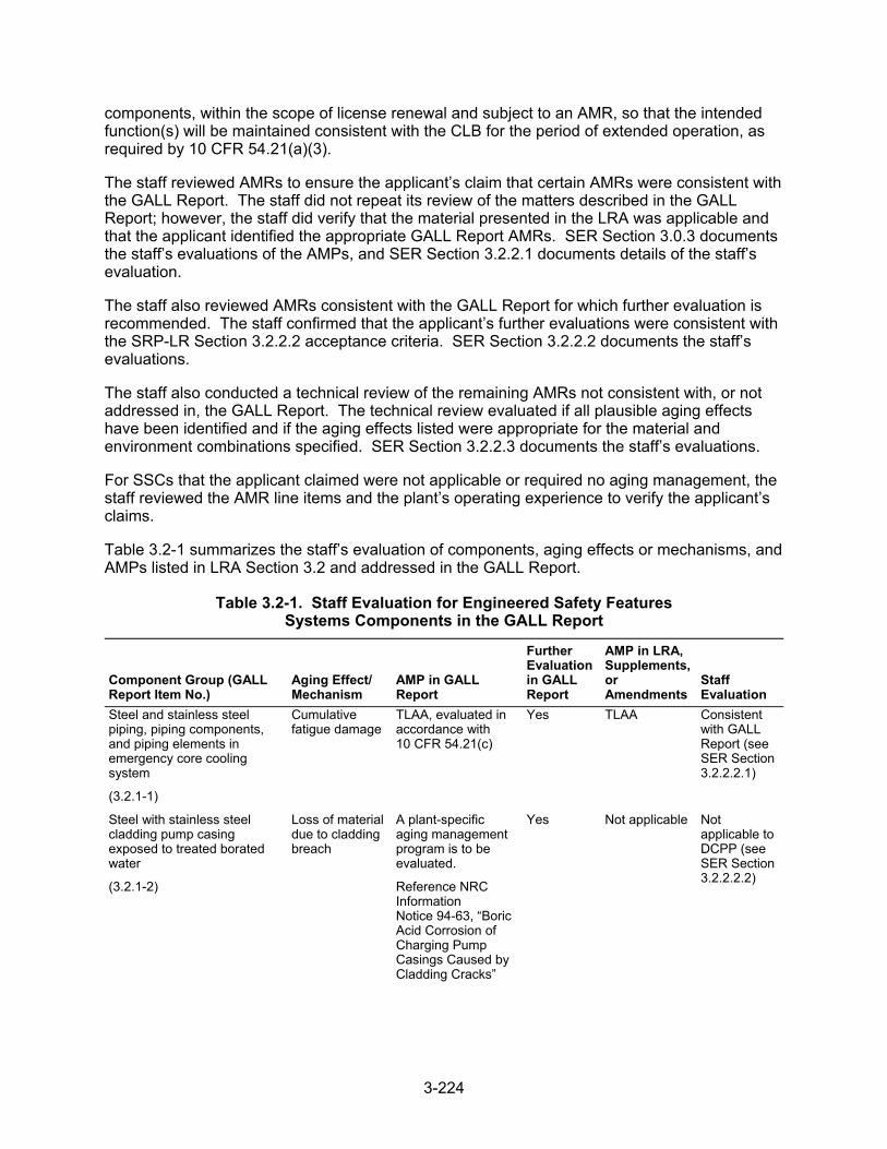
3-224
components, within the scope of license renewal and subject to an AMR, so that the intended function(s) will be maintained consistent with the CLB for the period of extended operation, as required by 10 CFR 54.21(a)(3).
The staff reviewed AMRs to ensure the applicant’s claim that certain AMRs were consistent with the GALL Report. The staff did not repeat its review of the matters described in the GALL Report; however, the staff did verify that the material presented in the LRA was applicable and that the applicant identified the appropriate GALL Report AMRs. SER Section 3.0.3 documents the staff’s evaluations of the AMPs, and SER Section 3.2.2.1 documents details of the staff’s evaluation.
The staff also reviewed AMRs consistent with the GALL Report for which further evaluation is recommended. The staff confirmed that the applicant’s further evaluations were consistent with the SRP-LR Section 3.2.2.2 acceptance criteria. SER Section 3.2.2.2 documents the staff’s evaluations.
The staff also conducted a technical review of the remaining AMRs not consistent with, or not addressed in, the GALL Report. The technical review evaluated if all plausible aging effects have been identified and if the aging effects listed were appropriate for the material and environment combinations specified. SER Section 3.2.2.3 documents the staff’s evaluations.
For SSCs that the applicant claimed were not applicable or required no aging management, the staff reviewed the AMR line items and the plant’s operating experience to verify the applicant’s claims.
Table 3.2-1 summarizes the staff’s evaluation of components, aging effects or mechanisms, and AMPs listed in LRA Section 3.2 and addressed in the GALL Report.
Table 3.2-1. Staff Evaluation for Engineered Safety Features Systems Components in the GALL Report
Component Group (GALL Report Item No.)
Aging Effect/ Mechanism
AMP in GALL Report
Further Evaluation in GALL Report
AMP in LRA, Supplements, or Amendments
Staff Evaluation
Steel and stainless steel piping, piping components, and piping elements in emergency core cooling system
(3.2.1-1)
Cumulative fatigue damage
TLAA, evaluated in accordance with 10 CFR 54.21(c)
Yes TLAA Consistent with GALL Report (see SER Section 3.2.2.2.1)
Steel with stainless steel cladding pump casing exposed to treated borated water
(3.2.1-2)
Loss of material due to cladding breach
A plant-specific aging management program is to be evaluated.
Reference NRC Information Notice 94-63, “Boric Acid Corrosion of Charging Pump Casings Caused by Cladding Cracks”
Yes Not applicable Not applicable to DCPP (see SER Section 3.2.2.2.2)
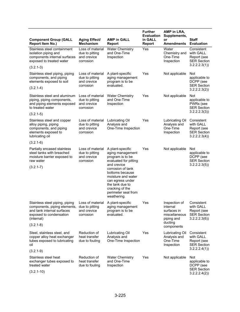
3-225
Component Group (GALL Report Item No.)
Aging Effect/ Mechanism
AMP in GALL Report
Further Evaluation in GALL Report
AMP in LRA, Supplements, or Amendments
Staff Evaluation
Stainless steel containment isolation piping and components internal surfaces exposed to treated water
(3.2.1-3)
Loss of materialdue to pitting and crevice corrosion
Water Chemistry and One-Time Inspection
Yes Water Chemistry and One-Time Inspection
Consistent with GALL Report (see SER Section 3.2.2.2.3(1))
Stainless steel piping, piping components, and piping elements exposed to soil
(3.2.1-4)
Loss of material due to pitting and crevice corrosion
A plant-specific aging management program is to be evaluated.
Yes Not applicable Not applicable to DCPP (see SER Section 3.2.2.2.3(2))
Stainless steel and aluminum piping, piping components, and piping elements exposed to treated water
(3.2.1-5)
Loss of material due to pitting and crevice corrosion
Water Chemistry and One-Time Inspection
Yes Not applicable Not applicable to PWRs (see SER Section 3.2.2.2.3(3))
Stainless steel and copper alloy piping, piping components, and piping elements exposed to lubricating oil
(3.2.1-6)
Loss of material due to pitting and crevice corrosion
Lubricating Oil Analysis and One-Time Inspection
Yes Lubricating Oil Analysis and One-Time Inspection
Consistent with GALL Report (see SER Section 3.2.2.2.3(4))
Partially encased stainless steel tanks with breached moisture barrier exposed to raw water
(3.2.1-7)
Loss of material due to pitting and crevice corrosion
A plant-specific aging management program is to be evaluated for pitting and crevice corrosion of tank bottoms because moisture and water can egress under the tank due to cracking of the perimeter seal from weathering.
Yes Not applicable Not applicable to DCPP (see SER Section 3.2.2.2.3(5))
Stainless steel piping, piping components, piping elements, and tank internal surfaces exposed to condensation (internal)
(3.2.1-8)
Loss of material due to pitting and crevice corrosion
A plant-specific aging management program is to be evaluated.
Yes Inspection of internal surfaces in miscellaneous piping and ducting components
Consistent with GALL Report (see SER Section 3.2.2.2.3(6))
Steel, stainless steel, and copper alloy heat exchanger tubes exposed to lubricating oil
(3.2.1-9)
Reduction of heat transfer due to fouling
Lubricating Oil Analysis and One-Time Inspection
Yes Lubricating Oil Analysis and One-Time Inspection
Consistent with GALL Report (see SER Section 3.2.2.2.4(1))
Stainless steel heat exchanger tubes exposed to treated water
(3.2.1-10)
Reduction of heat transfer due to fouling
Water Chemistry and One-Time Inspection
Yes Not applicable Not applicable to DCPP (see SER Section 3.2.2.2.4(2))
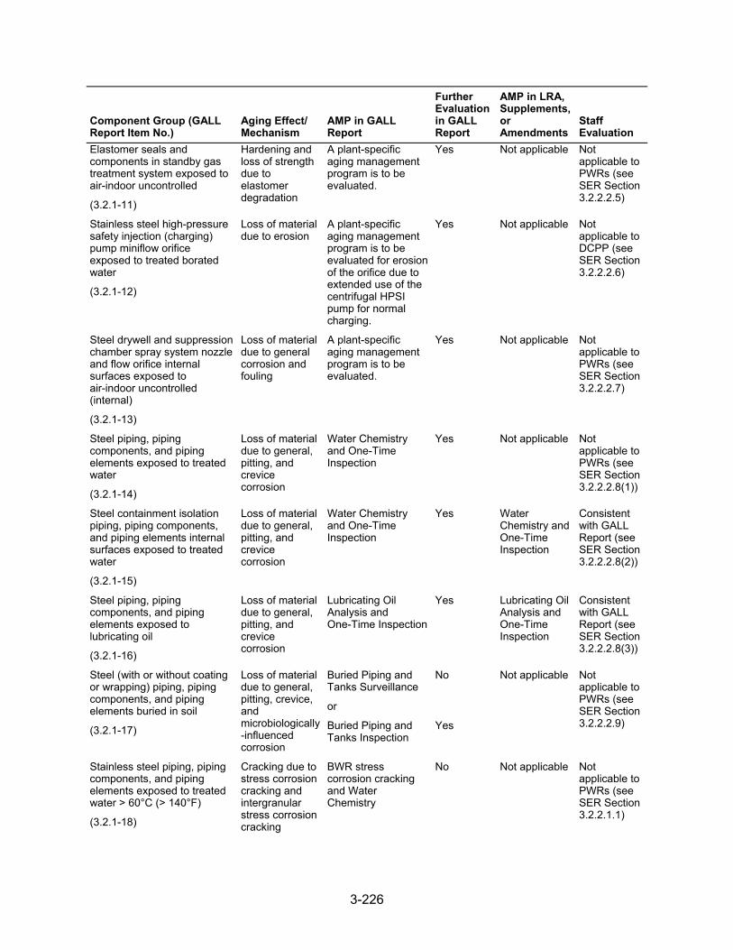
3-226
Component Group (GALL Report Item No.)
Aging Effect/ Mechanism
AMP in GALL Report
Further Evaluation in GALL Report
AMP in LRA, Supplements, or Amendments
Staff Evaluation
Elastomer seals and components in standby gas treatment system exposed to air-indoor uncontrolled
(3.2.1-11)
Hardening and loss of strength due to elastomer degradation
A plant-specific aging management program is to be evaluated.
Yes Not applicable Not applicable to PWRs (see SER Section 3.2.2.2.5)
Stainless steel high-pressure safety injection (charging) pump miniflow orifice exposed to treated borated water
(3.2.1-12)
Loss of material due to erosion
A plant-specific aging management program is to be evaluated for erosion of the orifice due to extended use of the centrifugal HPSI pump for normal charging.
Yes Not applicable Not applicable to DCPP (see SER Section 3.2.2.2.6)
Steel drywell and suppression chamber spray system nozzle and flow orifice internal surfaces exposed to air-indoor uncontrolled (internal)
(3.2.1-13)
Loss of material due to general corrosion and fouling
A plant-specific aging management program is to be evaluated.
Yes Not applicable Not applicable to PWRs (see SER Section 3.2.2.2.7)
Steel piping, piping components, and piping elements exposed to treated water
(3.2.1-14)
Loss of material due to general, pitting, and crevice corrosion
Water Chemistry and One-Time Inspection
Yes Not applicable Not applicable to PWRs (see SER Section 3.2.2.2.8(1))
Steel containment isolation piping, piping components, and piping elements internal surfaces exposed to treated water
(3.2.1-15)
Loss of material due to general, pitting, and crevice corrosion
Water Chemistry and One-Time Inspection
Yes Water Chemistry and One-Time Inspection
Consistent with GALL Report (see SER Section 3.2.2.2.8(2))
Steel piping, piping components, and piping elements exposed to lubricating oil
(3.2.1-16)
Loss of material due to general, pitting, and crevice corrosion
Lubricating Oil Analysis and One-Time Inspection
Yes Lubricating Oil Analysis and One-Time Inspection
Consistent with GALL Report (see SER Section 3.2.2.2.8(3))
Steel (with or without coating or wrapping) piping, piping components, and piping elements buried in soil
(3.2.1-17)
Loss of material due to general, pitting, crevice, and microbiologically-influenced corrosion
Buried Piping and Tanks Surveillance
or
Buried Piping and Tanks Inspection
No
Yes
Not applicable Not applicable to PWRs (see SER Section 3.2.2.2.9)
Stainless steel piping, piping components, and piping elements exposed to treated water > 60°C (> 140°F)
(3.2.1-18)
Cracking due to stress corrosion cracking and intergranular stress corrosion cracking
BWR stress corrosion cracking and Water Chemistry
No Not applicable Not applicable to PWRs (see SER Section 3.2.2.1.1)
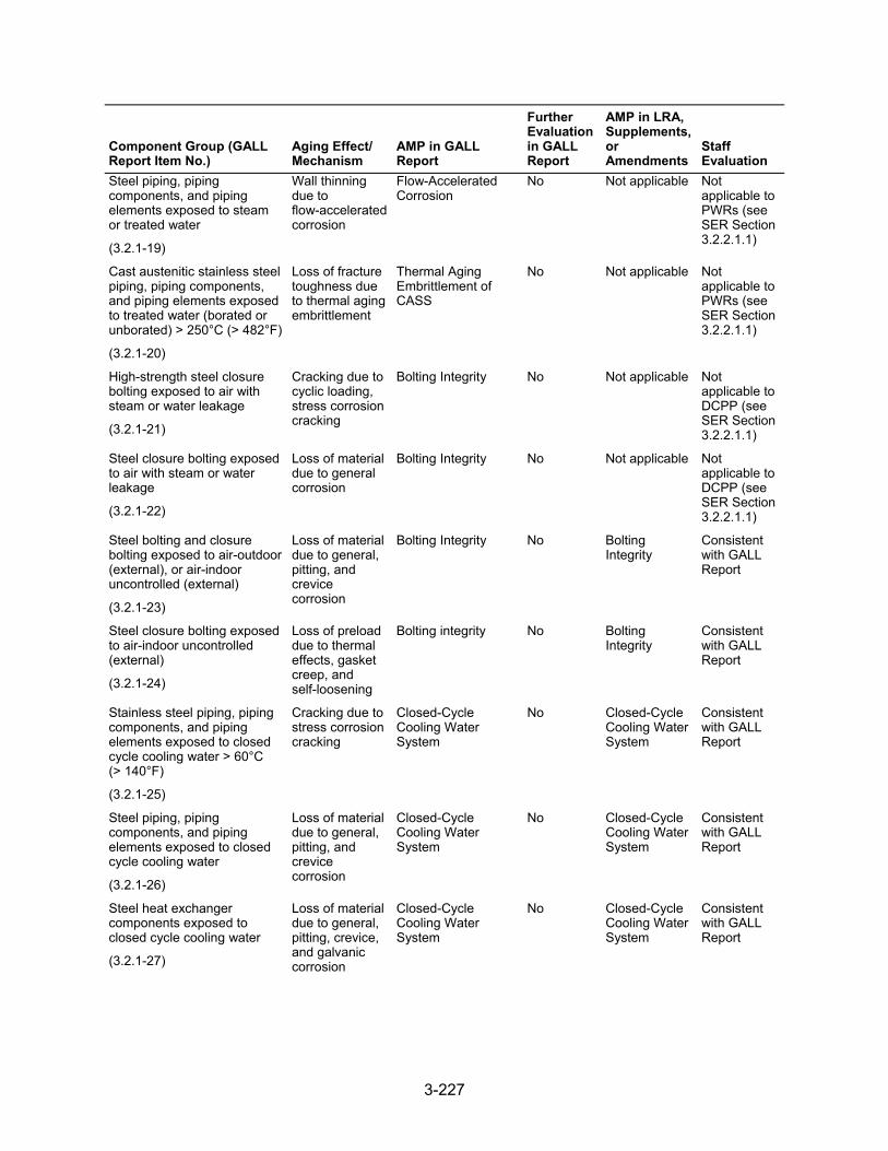
3-227
Component Group (GALL Report Item No.)
Aging Effect/ Mechanism
AMP in GALL Report
Further Evaluation in GALL Report
AMP in LRA, Supplements, or Amendments
Staff Evaluation
Steel piping, piping components, and piping elements exposed to steam or treated water
(3.2.1-19)
Wall thinning due to flow-accelerated corrosion
Flow-Accelerated Corrosion
No Not applicable Not applicable to PWRs (see SER Section 3.2.2.1.1)
Cast austenitic stainless steel piping, piping components, and piping elements exposed to treated water (borated or unborated) > 250°C (> 482°F)
(3.2.1-20)
Loss of fracture toughness due to thermal aging embrittlement
Thermal Aging Embrittlement of CASS
No Not applicable Not applicable to PWRs (see SER Section 3.2.2.1.1)
High-strength steel closure bolting exposed to air with steam or water leakage
(3.2.1-21)
Cracking due to cyclic loading, stress corrosion cracking
Bolting Integrity No Not applicable Not applicable to DCPP (see SER Section 3.2.2.1.1)
Steel closure bolting exposed to air with steam or water leakage
(3.2.1-22)
Loss of material due to general corrosion
Bolting Integrity No Not applicable Not applicable to DCPP (see SER Section 3.2.2.1.1)
Steel bolting and closure bolting exposed to air-outdoor (external), or air-indoor uncontrolled (external)
(3.2.1-23)
Loss of material due to general, pitting, and crevice corrosion
Bolting Integrity No Bolting Integrity
Consistent with GALL Report
Steel closure bolting exposed to air-indoor uncontrolled (external)
(3.2.1-24)
Loss of preload due to thermal effects, gasket creep, and self-loosening
Bolting integrity No Bolting Integrity
Consistent with GALL Report
Stainless steel piping, piping components, and piping elements exposed to closed cycle cooling water > 60°C (> 140°F)
(3.2.1-25)
Cracking due to stress corrosion cracking
Closed-Cycle Cooling Water System
No Closed-Cycle Cooling Water System
Consistent with GALL Report
Steel piping, piping components, and piping elements exposed to closed cycle cooling water
(3.2.1-26)
Loss of material due to general, pitting, and crevice corrosion
Closed-Cycle Cooling Water System
No Closed-Cycle Cooling Water System
Consistent with GALL Report
Steel heat exchanger components exposed to closed cycle cooling water
(3.2.1-27)
Loss of material due to general, pitting, crevice, and galvanic corrosion
Closed-Cycle Cooling Water System
No Closed-Cycle Cooling Water System
Consistent with GALL Report
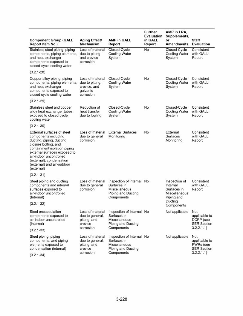
3-228
Component Group (GALL Report Item No.)
Aging Effect/ Mechanism
AMP in GALL Report
Further Evaluation in GALL Report
AMP in LRA, Supplements, or Amendments
Staff Evaluation
Stainless steel piping, piping components, piping elements, and heat exchanger components exposed to closed-cycle cooling water
(3.2.1-28)
Loss of material due to pitting and crevice corrosion
Closed-Cycle Cooling Water System
No Closed-Cycle Cooling Water System
Consistent with GALL Report
Copper alloy piping, piping components, piping elements, and heat exchanger components exposed to closed cycle cooling water
(3.2.1-29)
Loss of material due to pitting, crevice, and galvanic corrosion
Closed-Cycle Cooling Water System
No Closed-Cycle Cooling Water System
Consistent with GALL Report
Stainless steel and copper alloy heat exchanger tubes exposed to closed cycle cooling water
(3.2.1-30)
Reduction of heat transfer due to fouling
Closed-Cycle Cooling Water System
No Closed-Cycle Cooling Water System
Consistent with GALL Report
External surfaces of steel components including ducting, piping, ducting closure bolting, and containment isolation piping external surfaces exposed to air-indoor uncontrolled (external); condensation (external) and air-outdoor (external)
(3.2.1-31)
Loss of material due to general corrosion
External Surfaces Monitoring
No External Surfaces Monitoring
Consistent with GALL Report
Steel piping and ducting components and internal surfaces exposed to air-indoor uncontrolled (Internal)
(3.2.1-32)
Loss of material due to general corrosion
Inspection of internal Surfaces in Miscellaneous Piping and Ducting Components
No Inspection of Internal Surfaces in Miscellaneous Piping and Ducting Components
Consistent with GALL Report
Steel encapsulation components exposed to air-indoor uncontrolled (internal)
(3.2.1-33)
Loss of material due to general, pitting, and crevice corrosion
Inspection of Internal Surfaces in Miscellaneous Piping and Ducting Components
No Not applicable Not applicable to DCPP (see SER Section 3.2.2.1.1)
Steel piping, piping components, and piping elements exposed to condensation (internal)
(3.2.1-34)
Loss of material due to general, pitting, and crevice corrosion
Inspection of Internal Surfaces in Miscellaneous Piping and Ducting Components
No Not applicable Not applicable to PWRs (see SER Section 3.2.2.1.1)
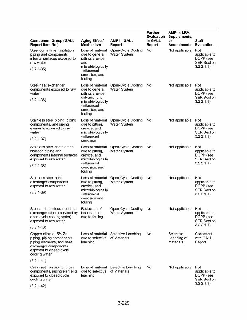
3-229
Component Group (GALL Report Item No.)
Aging Effect/ Mechanism
AMP in GALL Report
Further Evaluation in GALL Report
AMP in LRA, Supplements, or Amendments
Staff Evaluation
Steel containment isolation piping and components internal surfaces exposed to raw water
(3.2.1-35)
Loss of material due to general, pitting, crevice, and microbiologically-influenced corrosion, and fouling
Open-Cycle Cooling Water System
No Not applicable Not applicable to DCPP (see SER Section 3.2.2.1.1)
Steel heat exchanger components exposed to raw water
(3.2.1-36)
Loss of material due to general, pitting, crevice, galvanic, and microbiologically-influenced corrosion, and fouling
Open-Cycle Cooling Water System
No Not applicable Not applicable to DCPP (see SER Section 3.2.2.1.1)
Stainless steel piping, piping components, and piping elements exposed to raw water
(3.2.1-37)
Loss of material due to pitting, crevice, and microbiologically-influenced corrosion
Open-Cycle Cooling Water System
No Not applicable Not applicable to DCPP (see SER Section 3.2.2.1.1)
Stainless steel containment isolation piping and components internal surfaces exposed to raw water
(3.2.1-38)
Loss of material due to pitting, crevice, and microbiologically-influenced corrosion, and fouling
Open-Cycle Cooling Water System
No Not applicable Not applicable to DCPP (see SER Section 3.2.2.1.1)
Stainless steel heat exchanger components exposed to raw water
(3.2.1-39)
Loss of material due to pitting, crevice, and microbiologically-influenced corrosion and fouling
Open-Cycle Cooling Water System
No Not applicable Not applicable to DCPP (see SER Section 3.2.2.1.1)
Steel and stainless steel heat exchanger tubes (serviced by open-cycle cooling water) exposed to raw water
(3.2.1-40)
Reduction of heat transfer due to fouling
Open-Cycle Cooling Water System
No Not applicable Not applicable to DCPP (see SER Section 3.2.2.1.1)
Copper alloy > 15% Zn piping, piping components, piping elements, and heat exchanger components exposed to closed cycle cooling water
(3.2.1-41)
Loss of material due to selective leaching
Selective Leaching of Materials
No Selective Leaching of Materials
Consistent with GALL Report
Gray cast iron piping, piping components, piping elements exposed to closed-cycle cooling water
(3.2.1-42)
Loss of material due to selective leaching
Selective Leaching of Materials
No Not applicable Not applicable to DCPP (see SER Section 3.2.2.1.1)
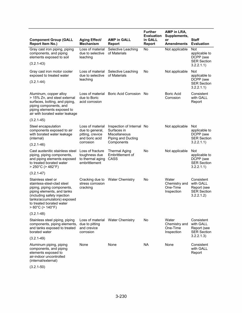
3-230
Component Group (GALL Report Item No.)
Aging Effect/ Mechanism
AMP in GALL Report
Further Evaluation in GALL Report
AMP in LRA, Supplements, or Amendments
Staff Evaluation
Gray cast iron piping, piping components, and piping elements exposed to soil
(3.2.1-43)
Loss of material due to selective leaching
Selective Leaching of Materials
No Not applicable Not applicable to DCPP (see SER Section 3.2.2.1.1)
Gray cast iron motor cooler exposed to treated water
(3.2.1-44)
Loss of material due to selective leaching
Selective Leaching of Materials
No Not applicable Not applicable to DCPP (see SER Section 3.2.2.1.1)
Aluminum, copper alloy > 15% Zn, and steel external surfaces, bolting, and piping, piping components, and piping elements exposed to air with borated water leakage
(3.2.1-45)
Loss of material due to Boric acid corrosion
Boric Acid Corrosion No Boric Acid Corrosion
Consistent with GALL Report
Steel encapsulation components exposed to air with borated water leakage (internal)
(3.2.1-46)
Loss of material due to general, pitting, crevice and boric acid corrosion
Inspection of Internal Surfaces in Miscellaneous Piping and Ducting Components
No Not applicable Not applicable to DCPP (see SER Section 3.2.2.1.1)
Cast austenitic stainless steel piping, piping components, and piping elements exposed to treated borated water > 250°C (> 482°F)
(3.2.1-47)
Loss of fracture toughness due to thermal aging embrittlement
Thermal Aging Embrittlement of CASS
No Not applicable Not applicable to DCPP (see SER Section 3.2.2.1.1)
Stainless steel or stainless-steel-clad steel piping, piping components, piping elements, and tanks (including safety injection tanks/accumulators) exposed to treated borated water > 60°C (> 140°F)
(3.2.1-48)
Cracking due to stress corrosion cracking
Water Chemistry No Water Chemistry and One-Time Inspection
Consistent with GALL Report (see SER Section 3.2.2.1.2)
Stainless steel piping, piping components, piping elements, and tanks exposed to treated borated water
(3.2.1-49)
Loss of material due to pitting and crevice corrosion
Water Chemistry No Water Chemistry and One-Time Inspection
Consistent with GALL Report (see SER Section 3.2.2.1.3)
Aluminum piping, piping components, and piping elements exposed to air-indoor uncontrolled (internal/external)
(3.2.1-50)
None None NA None Consistent with GALL Report
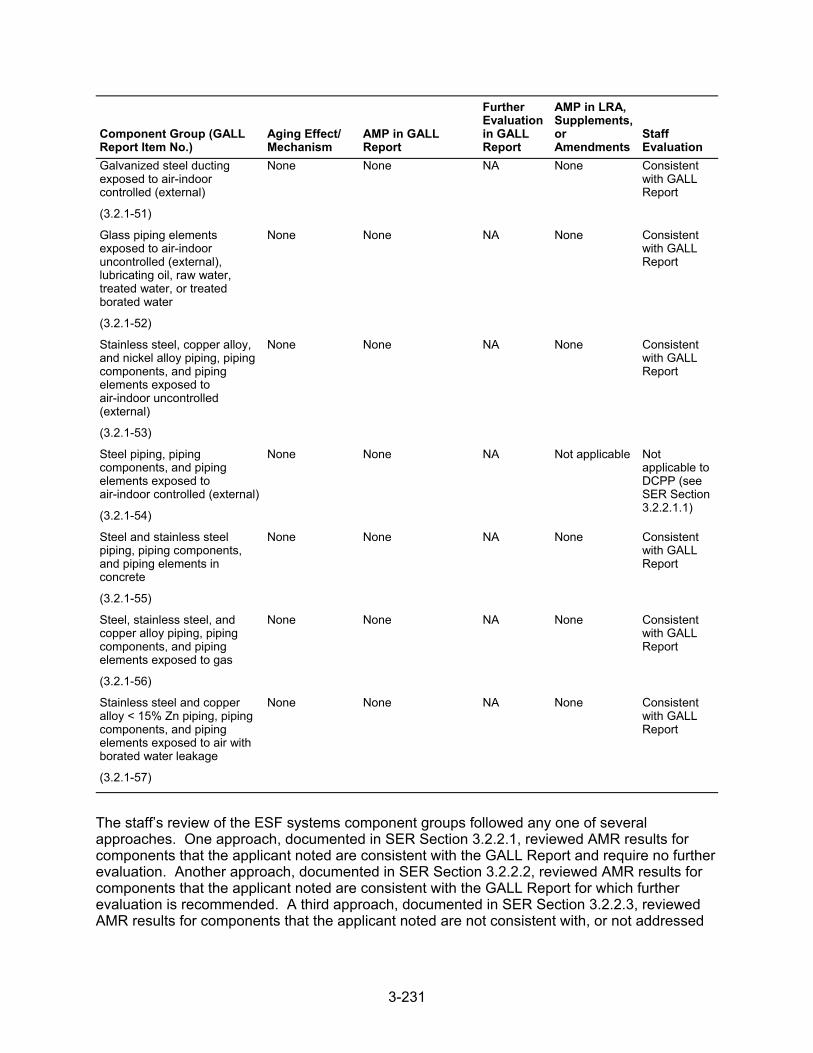
3-231
Component Group (GALL Report Item No.)
Aging Effect/ Mechanism
AMP in GALL Report
Further Evaluation in GALL Report
AMP in LRA, Supplements, or Amendments
Staff Evaluation
Galvanized steel ducting exposed to air-indoor controlled (external)
(3.2.1-51)
None None NA None Consistent with GALL Report
Glass piping elements exposed to air-indoor uncontrolled (external), lubricating oil, raw water, treated water, or treated borated water
(3.2.1-52)
None None NA None Consistent with GALL Report
Stainless steel, copper alloy, and nickel alloy piping, piping components, and piping elements exposed to air-indoor uncontrolled (external)
(3.2.1-53)
None None NA None Consistent with GALL Report
Steel piping, piping components, and piping elements exposed to air-indoor controlled (external)
(3.2.1-54)
None None NA Not applicable Not applicable to DCPP (see SER Section 3.2.2.1.1)
Steel and stainless steel piping, piping components, and piping elements in concrete
(3.2.1-55)
None None NA None Consistent with GALL Report
Steel, stainless steel, and copper alloy piping, piping components, and piping elements exposed to gas
(3.2.1-56)
None None NA None Consistent with GALL Report
Stainless steel and copper alloy < 15% Zn piping, piping components, and piping elements exposed to air with borated water leakage
(3.2.1-57)
None None NA None Consistent with GALL Report
The staff’s review of the ESF systems component groups followed any one of several approaches. One approach, documented in SER Section 3.2.2.1, reviewed AMR results for components that the applicant noted are consistent with the GALL Report and require no further evaluation. Another approach, documented in SER Section 3.2.2.2, reviewed AMR results for components that the applicant noted are consistent with the GALL Report for which further evaluation is recommended. A third approach, documented in SER Section 3.2.2.3, reviewed AMR results for components that the applicant noted are not consistent with, or not addressed
3-232
in, the GALL Report. SER Section 3.0.3 documents the staff’s review of AMPs credited to manage or monitor aging effects of the ESF systems components.
3.2.2.1 AMR Results Consistent with the GALL Report
LRA Section 3.2.2.1 notes the materials, environments, AERMs, and the following programs that manage aging effects for the ESF systems components:
ASME Section XI Inservice Inspection, Subsections IWB, IWC, and IWD Bolting Integrity Boric Acid Corrosion Closed-Cycle Cooling Water System External Surfaces Monitoring Inspection of Internal Surfaces in Miscellaneous Piping and Ducting Components Lubricating Oil Analysis One-Time Inspection One-Time Inspection of ASME Code Class 1 Small-Bore Piping Selective Leaching of Materials Water Chemistry
LRA Tables 3.2.2-1 through 3.2.2-5 summarize AMRs for the ESF systems components and note AMRs claimed to be consistent with the GALL Report.
As discussed in SER Section 3.0.2.2.2, the applicant provided AMR results which cited generic notes A through J to indicate the AMR’s consistency with the GALL Report. The staff reviewed the information in the LRA for AMRs that the applicant claimed were consistent with the GALL Report (i.e., those AMR items the applicant cited generic notes A through E). The staff did not repeat its review of the matters described in the GALL Report; however, the staff did verify that the material presented in the LRA was applicable and that the applicant identified the appropriate GALL Report AMRs.
The staff reviewed the LRA to confirm that the applicant: (a) provided a brief description of the system, components, materials, and environments; (b) stated that the applicable aging effects were reviewed and evaluated in the GALL Report; and (c) identified those aging effects for the ESF systems components that are subject to an AMR. For those AMRs that the applicant claimed consistency, the staff compared the LRA AMRs to the corresponding GALL Report AMRs to verify the applicant’s claim of consistency. The staff’s evaluation follows.
3.2.2.1.1 AMR Results Identified as Not Applicable
LRA Table 3.2.1, items 3.2.1.18 through 3.2.1.20, and 3.2.1.34, state that these line items are applicable only to BWRs. The staff verified that these line items do not apply because the units are a PWR design. Based on this determination, the staff finds that the applicant has provided an acceptable basis for concluding AMR items 3.2.1.18 through 3.2.1.20, and 3.2.1.34, are not applicable.
LRA Table 3.2.1, items 3.2.1.21, 3.2.1.22, 3.2.1.33, 3.2.1.36, 3.2.1.37, 3.2.1.38, 3.2.1.39, 3.2.1.40, 3.2.1.42, 3.2.1.43, 3.2.1.44, and 3.2.1.46 state that these items are not applicable to DCPP. The staff reviewed the LRA and FSAR and confirmed that the applicant’s LRA does not have any AMR results that are applicable for these line items.
LRA Table 3.2.1, item 3.2.1.35, addresses steel containment isolation piping and components internal surfaces exposed to raw water. The GALL Report recommends use of
3-233
GALL AMP XI.M20, “Open-Cycle Cooling Water System,” Program to manage loss of material due to general, pitting, crevice, and MIC and fouling for this component group. The applicant stated that it did not use this line item because the containment isolation components were evaluated in the systems in which the components were found to have the function of containment integrity. The staff finds this acceptable because the GALL Report does not recommend further evaluation of these components, and the approach proposed by the applicant will subject the components to comparable aging management. In addition, the staff reviewed LRA Sections 2.3.2 and 3.2 and the FSAR and confirmed that there are no in-scope steel piping components exposed to raw water in the ESF systems. Therefore, the staff finds the applicant's determination acceptable.
LRA Table 3.2.1, item 3.2.1.47, addresses the loss of fracture toughness due to thermal aging embrittlement in CASS piping, piping components, and piping elements in the ESF exposed to treated borated water greater than 250 °C (482 °F). The applicant stated that this line item is not applicable because it has no in-scope CASS piping, piping components, and piping elements exposed to treated borated water greater than 250 °C (482 °F). The staff reviewed the applicant’s FSAR and confirmed that no in-scope CASS piping, piping components, and piping elements exposed to treated borated water 250 °C (482 °F) are present in the ESF systems. Therefore, the staff finds the applicant’s determination acceptable.
LRA Table 3.2.1, item 3.2.1.54, addresses steel piping, piping components, and piping elements exposed to air-indoor controlled (external). The GALL Report recommends that there is no AERM and there is no recommended AMP. The applicant stated that this line item is not applicable because there are no in-scope steel components in the ESF systems. The staff noted that, based on a review of the applicant’s FSAR, nearly all the components in the ESF systems are constructed of stainless steel; however, FSAR Table 6.3-3 states that some motor-operated valves that contain non-radioactive, boron-free fluids, and some relief valve bodies and bonnets, are constructed of steel. Nevertheless, the staff finds the applicant’s proposal acceptable because, even with the steel components as described in the FSAR, the effect on the application is inconsequential because the GALL Report states that there is no AERM or recommended AMP for steel components exposed to air-indoor controlled.
3.2.2.1.2 Cracking Due to Stress Corrosion Cracking
LRA Table 3.2.1, item 3.2.1.48, addresses stainless steel components exposed to treated borated water, which are being managed for cracking due to SCC. The LRA credits the Water Chemistry and One-Time Inspection Programs to manage the aging effect. The GALL Report recommends GALL AMP XI.M2, “Water Chemistry,” to ensure that these aging effects are adequately managed. The AMR line items cite generic note E.
For those line items associated with generic note E, GALL AMP XI.M2 recommends using sampling, analyzing, and controlling water chemistry in accordance with the EPRI water chemistry guidelines to manage the aging effect of these line items. In its review of components associated with LRA Table 3.2.1, item 3.2.1.48, for which the applicant cited generic note E, the staff also noted that the Water Chemistry and One-Time Inspection Programs propose to manage the aging of stainless steel components through the use of sampling, analyzing, and controlling water chemistry in accordance with the EPRI water chemistry guidelines, augmented with a one-time inspection of selected components at susceptible locations to verify the effectiveness of the water chemistry.
SER Sections 3.0.3.1.2 and 3.0.3.1.10 document the staff’s evaluation of the applicant’s Water Chemistry and One-Time Inspection Programs, respectively. In its review of components
3-234
associated with item 3.2.1.48, the staff finds the applicant’s proposal to manage aging using the Water Chemistry and One-Time Inspection Programs acceptable for the following reasons:
The Water Chemistry Program establishes the plant water chemistry control parameters and, if the parameters exceed limits, identifies and performs the required actions to control the water chemistry such that SCC of the components is mitigated, consistent with the recommendation of the GALL Report.
The applicant conservatively credits its One-Time Inspection Program, which includes an adequate one-time NDE of selected components, to confirm that the effectiveness of the Water Chemistry Program is adequate to manage cracking due to SCC.
The staff concludes that the applicant has demonstrated that it will adequately manage the effects of aging for these components so that the intended function(s) will be maintained consistent with the CLB during the period of extended operation, as required by 10 CFR 54.21(a)(3).
3.2.2.1.3 Loss of Material Due to Pitting and Crevice Corrosion
LRA Table 3.2.1, item 3.2.1.49, addresses stainless steel piping, piping components, piping elements, and tanks exposed to treated borated water which are being managed for loss of material due to pitting and crevice corrosion. The LRA credits the Water Chemistry and One-Time Inspection Programs to manage the aging effect. The GALL Report recommends GALL AMP XI.M2, “Water Chemistry Program,” to ensure that these aging effects are adequately managed. The associated AMR line items cite generic note E.
For those line items associated with generic note E, GALL AMP XI.M2 recommends using mitigation measures, such as maintaining low levels of corrosive impurities by maintaining the chemical environment through water chemistry controls, based on industry guidelines, to manage the aging of these items. In its review of components associated with LRA Table 3.2.1, item 3.2.1.49, for which the applicant cited generic note E, the staff noted that the Water Chemistry and the One-Time Inspection Programs propose to manage the aging of stainless steel piping, piping components, piping elements, and tanks exposed to treated borated water through the use of mitigation measures, based on industry guidelines, such as maintaining low levels of known detrimental contaminants. In addition, a one-time inspection will verify the effectiveness of the Water Chemistry Program in low-flow and stagnant-flow areas.
SER Section 3.0.3.1.2 and 3.0.3.1.10 document the staff’s evaluation of the applicant’s Water Chemistry and One-Time Inspection Programs, respectively. In its review of components associated with LRA Table 3.2.1, item 3.2.1.49, the staff finds the applicant’s proposal to manage aging using the specified programs acceptable because the Water Chemistry Program will monitor and control the chemical environment to ensure that the aging effects due to contaminants are limited, and the One-Time Inspection Program will verify the effectiveness of the Water Chemistry Program for managing the effects of aging due to the potential corrosion mechanisms.
The staff concludes that the applicant has demonstrated that it will adequately manage the effects of aging for these components so that their intended function(s) will be maintained consistent with the CLB during the period of extended operation, as required by 10 CFR 54.21(a)(3).
3-235
3.2.2.1.4 Conclusion
The staff evaluated the GALL Report AMR items that the applicant claimed were not applicable. On the basis of its review, the staff concludes that the AMR results which the applicant claimed were not applicable.
As discussed in SER Section 3.2.2.1, for those AMRs that the applicant claimed consistency with the GALL Report, the staff evaluated the applicant’s claim of consistency. The staff also reviewed information pertaining to the applicant’s consideration of recent operating experience and proposals for managing aging effects. On the basis of its review, the staff concludes that the AMR results, which the applicant claimed to be consistent with the GALL Report, are consistent.
Therefore, the staff concludes that the applicant has demonstrated that the effects of aging for these components will be adequately managed so that their intended function(s) will be maintained consistent with the CLB during the period of extended operation, as required by 10 CFR 54.21(a)(3).
3.2.2.2 AMR Results Consistent with the GALL Report for Which Further Evaluation Is Recommended
In LRA Section 3.2.2.2, the applicant further evaluates aging management, as recommended by the GALL Report, for the ESF systems components and provides information concerning how it will manage the following aging effects:
cumulative fatigue damage loss of material due to cladding breach loss of material due to pitting and crevice corrosion reduction of heat transfer due to fouling hardening and loss of strength due to elastomer degradation loss of material due to erosion loss of material due to general corrosion and fouling loss of material due to general, pitting, and crevice corrosion loss of material due to general, pitting, crevice, and MIC QA for aging management of nonsafety-related components
For component groups evaluated in the GALL Report, for which the applicant claimed consistency with the report and for which the report recommends further evaluation, the staff reviewed the applicant’s evaluation to determine if it adequately addressed the issues further evaluated. In addition, the staff reviewed the applicant’s further evaluations against the criteria contained in SRP-LR Section 3.2.2.2. The staff’s review of the applicant’s further evaluation follows.
3.2.2.2.1 Cumulative Fatigue Damage
LRA Section 3.2.2.2.1 states that cumulative fatigue damage of engineered safety features piping is a TLAA as defined in 10 CFR 54.3. TLAAs are evaluated in accordance with 10 CFR 54.21(c)(1). The applicant further stated ESF piping is designed to ASME Code Class 2, Class 3, and ANSI B31.1, all of which require a reduction in the allowable secondary stress range if more than 7,000 full-range thermal cycles are expected in a design lifetime. LRA Section 4.3.5 describes the evaluation of these cyclic design TLAAs.
3-236
The staff reviewed LRA Section 3.2.2.2.1 against the criteria in SRP-LR Section 3.2.2.2.1, which states that fatigue is a TLAA, as defined in 10 CFR 54.3. TLAAs are required to be evaluated in accordance with 10 CFR 54.21(c)(1). The staff also reviewed the AMRs discussed in this section against the GALL Report items for evaluating cumulative fatigue damage in PWR ESF designs, as given in the GALL Report, Volume 2, Revision 1, Section V.
GALL Report, item V.D1-27, notes that cumulative fatigue damage is an applicable aging effect for steel and stainless steel piping, piping components, and piping elements in the ECCS and recommends that the TLAA on metal fatigue be used to manage the affect of cumulative fatigue damage in these components. The staff noted that, consistent with this recommendation, the applicant included applicable line items in LRA Tables 3.2.2-1 and 3.2.2-3 for piping, piping components, and pipe fittings, in the RHR system SI systems, that received ASME Section III CUF or ANSI B31.1 design code analysis calculations. The staff finds this acceptable because the inclusion of the applicable AMR items is consistent with the recommendations in the referenced GALL Report items and the recommendations in SRP-LR Section 3.2.2.2.1.
The staff noted that the applicant did not include any AMR items in LRA Table 3.2.2-2 for the safety injection system and LRA Table 3.2.2-4 for the RHR system. The staff noted that once the applicant has identified a given subsystem as within the scope of license renewal, under 10 CFR 54.4, and screened it in for an AMR, under 10 CFR 54.21(a)(1), the lack of a GALL Report item is not a basis that a given component would not need to be included in the LRA with the associated AMR line item. LRA Section 4.3.5 notes that the ANSI B31.1 and B31.7 piping components were required to receive implicit fatigue analyses under the ANSI B31.1 and B31.7 design codes. The staff noted that the LRA should also include applicable GALL Report items on cumulative fatigue damage if the systems include ANSI B31.1 or B31.7 piping that is within the scope of license renewal and subject to an AMR under 10 CFR 54.21(a)(1). By letter dated August 25, 2010, the staff issued RAI 4.3-12, request 2, asking the applicant to explain why LRA Tables 3.2.2-2 and 3.2.2-4 do not appear to include any line items on management of cumulative fatigue damage for the ANSI B31.1 or B31.7 piping components in the RHR and SI systems.
In its response dated September 22, 2010, the applicant clarified that the piping, piping components, and pipe elements in the containment HVAC system were not designed to either ANSI B31.1 design requirements or ASME Section III design requirements for Class 2 or 3 components. The applicant also clarified that, with the exception of the containment HVAC system, the piping, piping components, and piping fitting for the remaining ESF systems were designed to either ASME Section III requirements for Class 2 or 3 components or to the ANSI B31.1 design code, the components are within the scope of license renewal, and the components are subject to analysis of cumulative fatigue damage through the application of a time-dependent stress range reduction factor analysis. The applicant stated, however, that the inclusion of the applicable AMR items on cumulative fatigue damage for these systems would only reference the applicable LRA Chapter 4 TLAA for the disposition of the aging effect.
The staff determined that the applicant’s basis for not including the relevant AMR item on cumulative fatigue damage for piping, piping components, and piping elements in the containment HVAC system acceptable because the system was not designed to ASME Section III requirements for Class 2 or 3 components or to ANSI B31.1 or B31.7 requirements, and as a result, time dependent maximum allowable stress reduction factor calculations were not required for this system. However, the staff noted that the applicant’s response to RAI 4.3-12, request 2, identifies that cumulative fatigue damage is an applicable aging effect for ASME Code Class 2 or 3 or ANSI B31.1 piping, piping components and pipe fittings in the remaining ESF systems. The staff also noted that the applicant did not include the applicable AMR item for the containment spray system. Therefore, based on its review, the staff finds that
3-237
the applicant’s response to RAI 4.3-12, request 2, does not comply with the GALL Report recommendations for including an AMR item on cumulative fatigue damage for piping, piping components, or piping elements in the containment spray system that were designed to either ASME Section III requirements for Class 2 or 3 components or to ANSI B31.1 requirements. By letter dated December 20, 2010, the staff issued RAI 4.3-12 (follow-up), asking the applicant to justify why it did not include AMR items on cumulative fatigue damage for piping, piping components, and piping elements in the containment spray system that were designed to either ASME Section III requirements for Class 2 or 3 components or to ANSI B31.1 requirements. This is identified as Open Item 4.3-1. SER Section 4.3.5 documents the staff’s evaluation of the applicant's TLAA analysis for the ESF components.
Based on its review, pending acceptable resolution of RAI 4.3-12 (follow-up), the staff concludes that the applicant meets SRP-LR Section 3.2.2.2.1 criteria. For those line items that apply to LRA Section 3.2.2.2.1, the staff determines, with the exception of Open Item 4.3-1, that the LRA is consistent with the GALL Report and that the applicant has demonstrated that it will adequately manage the effects of aging so that the intended function(s) will be maintained consistent with the CLB during the period of extended operation, as required by 10 CFR 54.21(a)(3).
3.2.2.2.2 Loss of Material Due to Cladding Breach
LRA Section 3.2.2.2.2, associated with LRA Table 3.2.1, item 3.2.1.02, addresses loss of material due to cladding breach in steel with stainless steel cladding pump casings exposed to treated borated water. The applicant stated that this line item is not applicable because there are no in-scope steel with stainless steel cladding pump casings exposed to treated borated water in ECCSs. The staff reviewed LRA Sections 2.3.2 and 3.2 and the FSAR and confirmed that no in-scope steel with stainless steel cladding pump casings exposed to treated borated water are present in the ESF systems and, therefore, finds the applicant’s determination acceptable.
Based on the above, the staff concludes that SRP-LR Section 3.2.2.2.2 criteria do not apply.
3.2.2.2.3 Loss of Material Due to Pitting and Crevice Corrosion
(1) LRA Section 3.2.2.2.3, item 1, referenced by LRA Table 3.2.1, item 3.2.1.03, addresses stainless steel containment isolation piping and components internal surfaces exposed to treated water, which are being managed for loss of material due to pitting and crevice corrosion by the Water Chemistry and One-Time Inspection Programs. The applicant addressed the further evaluation requirements by stating that the loss of material due to pitting and crevice corrosion of stainless steel components exposed to demineralized water will be managed by the Water Chemistry and One-Time Inspection Programs. The applicant also stated that the One-Time Inspection Program includes selected components at susceptible locations where contaminants could accumulate (e.g., stagnant flow locations).
The staff reviewed LRA Section 3.2.2.2.3.1 against the criteria described in SRP-LR Section 3.2.2.2.3, item 1, which states that loss of material due to pitting and crevice corrosion could occur for the applicable components exposed to treated water, and the existing AMP relies on monitoring and control of water chemistry to mitigate degradation. However, because control of water chemistry does not prevent this aging effect at locations of stagnant flow conditions, the GALL Report recommends that the effectiveness of the Chemistry Control Program be verified and states that a one-time
3-238
inspection of select components at susceptible locations is an acceptable verification method.
SER Sections 3.0.3.1.2 and 3.0.3.1.10 document the staff’s evaluation of the applicant’s Water Chemistry and One-Time Inspection Programs, respectively. In its review of components associated with LRA Table 3.2.1, item 3.2.1.03, the staff finds the applicant’s proposal to manage aging using the specified programs acceptable because the Water Chemistry Program will monitor and control the chemical environment to ensure that the aging effects due to contaminants are limited, and the One-Time Inspection Program will verify the effectiveness of the Water Chemistry Program for managing the effects of aging due to the potential corrosion mechanisms.
(2) LRA Section 3.2.2.2.3.2, associated with LRA Table 3.2.1, item 3.2.1.04, addresses loss of material due to pitting and crevice corrosion in stainless steel piping, piping components, and piping elements exposed to soil. The applicant stated that this item is not applicable because there are no stainless steel piping, piping components, or piping elements exposed to soil in the ECCS. The staff reviewed LRA Sections 2.3 and 3.2 and the FSAR and confirmed that no in-scope stainless steel piping, piping components, and piping elements exposed to soil are present in the ECCS. Therefore, the staff finds the applicant’s determination acceptable.
(3) LRA Section 3.2.2.2.3 addresses loss of material due to pitting and crevice corrosion in BWR stainless steel and aluminum piping and components exposed to treated water, stating that this aging effect is not applicable to DCPP; it is applicable to BWRs only. SRP-LR Section 3.2.2.2.3 states that loss of material due to pitting and crevice corrosion may occur in BWR stainless steel and aluminum piping, piping components, and piping elements exposed to treated water. The staff finds that SRP-LR Section 3.2.2.2.3, item 3, is not applicable to DCPP because DCPP units are PWRs, and the staff guidance in this SRP-LR section is only applicable to BWRs.
(4) LRA Section 3.2.2.2.3.4, associated with LRA Table 3.2.1, item 3.2.1.06, addresses stainless steel and copper piping and components exposed to lubricating oil, which are being managed for loss of material due to pitting and crevice corrosion by the Lubricating Oil Analysis and One-time Inspection Programs. The GALL Report, under items V.D1-18 and V.D1-24, recommends further evaluation of the applicant’s AMR results. The applicant stated that the One-time Inspection Program would include selected components at susceptible locations where contaminants such as water could accumulate.
The staff reviewed LRA Section 3.2.2.2.3.4 against the criteria in SRP-LR Section 3.2.2.2.3, item 4, which states loss of material from pitting and crevice corrosion could occur for stainless steel and copper-alloy piping, piping components, and piping elements exposed to lubricating oil. The existing program relies on the periodic sampling and analysis of lubricating oil to maintain contaminants within acceptable limits, thereby preserving an environment that is not conducive to corrosion. However, control of lube oil contaminants may not always have been adequate to prevent corrosion. Therefore, the effectiveness of lubricating oil control should be verified to ensure that corrosion is not occurring. The GALL Report recommends further evaluation to verify the effectiveness of the lubricating oil program. A one-time inspection of selected components at susceptible locations is an acceptable method to ensure that corrosion is not occurring and that the component's intended function will be maintained during the period of extended operation.
SER Section 3.0.3.2.12 documents the staff’s evaluation of the applicant’s Lubricating Oil Analysis Program, and the staff determined that it is consistent with the GALL
3-239
Report. In its review of components associated with LRA Table 3.2.1, item 3.2.1.06, the staff finds the applicant’s proposal to manage aging using the Lubricating Oil Analysis and One-time Inspection Programs acceptable because this meets the acceptance criteria in SRP-LR Section 3.2.2.2.3.4. Therefore, the applicant’s AMR is consistent with the AMR under GALL Report items V.D1-18 and V.D1-24.
(5) LRA Section 3.2.2.2.3.5, associated with LRA Table 3.2.1, item 3.2.1.07, addresses loss of material due to pitting and crevice corrosion in partially encased stainless steel tanks with breached moisture barrier exposed to raw water. The applicant stated that this item is not applicable because there are no stainless steel tanks with a moisture barrier configuration exposed to raw water in the ECCS. The staff reviewed LRA Sections 2.3 and 3.2 and the FSAR and confirmed that no in-scope stainless steel tanks with breached moisture barrier exposed to raw water are present in the ECCS. Therefore, the staff finds the applicant’s determination acceptable.
(6) LRA Section 3.2.2.2.3.6, referenced by LRA Table 3.2.1, item 3.2.1.08, addresses stainless steel piping, piping components, piping elements, and tank internal surfaces exposed to internal condensation, which are being managed for loss of material due to pitting and crevice corrosion. The applicant addressed the further evaluation criteria of the SRP-LR by stating that the Inspection of Internal Surfaces in Miscellaneous Piping and Ducting Components Program will manage loss of material due to pitting and crevice corrosion of the stainless steel internal surfaces exposed to condensation environment.
The staff reviewed LRA Section 3.2.2.2.3.6 against the criteria described in SRP-LR Section 3.2.2.2.3, item 6, which states that loss of material due to pitting and crevice corrosion could occur for stainless steel piping, piping components, piping elements, and tanks exposed to internal condensation. The GALL Report recommends further evaluation of a plant-specific AMP and states that the acceptance criteria are described in BTP RSLB-1 of the SRP-LR.
SER Section 3.0.3.2.11 documents the staff’s evaluation of the applicant’s Inspection of Internal Surfaces in Miscellaneous Piping and Ducting Components. In its review of components associated with LRA Table 3.2.1, item 3.2.1.08, the staff finds the applicant’s proposal to manage aging using the Internal Surfaces in Miscellaneous Piping and Ducting Components Program acceptable because the credited program requires visual inspections, which are capable of detecting loss of material due to pitting and crevice corrosion.
Based on the programs noted above, the staff concludes that the applicant’s programs meet SRP-LR Section 3.2.2.2.3 criteria. For those line items that apply to LRA Section 3.2.2.2.3, the staff determines that the LRA is consistent with the GALL Report and that the applicant has demonstrated that it will adequately manage the effects of aging so that the intended function(s) will be maintained consistent with the CLB during the period of extended operation, as required by 10 CFR 54.21(a)(3).
3.2.2.2.4 Reduction of Heat Transfer Due to Fouling
(1) LRA Section 3.2.2.2.4.1, referenced by LRA Table 3.2.1, item 3.2.1.09, addresses steel, stainless steel, and copper-alloy heat exchanger tubes exposed to lubricating oil, which are managed for reduction of heat transfer due to fouling by the Lubricating Oil Analysis and One-Time Inspection Programs. The applicant addressed the further evaluation criteria of the SRP-LR by stating that the effectiveness of the Lubricating Oil Analysis Program will be verified by One-Time Inspection Program, which includes selected
3-240
components at susceptible locations where contaminants such as water could accumulate.
The staff reviewed LRA Section 3.2.2.2.4.1 against the criteria in SRP-LR Section 3.2.2.2.4, item 1, which states that reduction in heat transfer due to fouling could occur for steel, stainless steel, and copper-alloy heat exchanger tubes exposed to lubricating oil. The SRP-LR also states that the existing AMP relies on monitoring and controlling lubricating oil chemistry to mitigate reduction of heat transfer but, because controls may not always have been adequate to prevent fouling, the effectiveness of lubricating oil chemistry controls should be verified. The SRP-LR further states that a one-time inspection of select components at susceptible locations is an acceptable method to ensure fouling is not occurring.
SER Sections 3.0.3.2.12 and 3.0.3.1.10 document the staff’s evaluation of the applicant’s Lubricating Oil Analysis and One-Time Inspection Programs, respectively. In its review of components associated with item 3.2.1.09, the staff finds the applicant’s proposal to manage aging using the specified programs acceptable because the Lubricating Oil Analysis Program periodically samples and analyzes lubricating oil to preserve an environment that does not promote fouling. In addition, the applicant will use the One-Time Inspection Program to verify the effectiveness of the Lubricating Oil Analysis Program by inspecting a sample of components, based on materials, environments, aging effects, aging mechanisms, and operating experience, to manage fouling in the ESF systems.
(2) LRA Section 3.2.2.2.4.2, referenced by LRA Table 3.2-1, item 3.2.1.10, addresses stainless steel heat exchanger tubes exposed to treated water. In LRA Section 3.2.2.2.4.2, the applicant addressed the further evaluation criteria of the SRP-LR by stating that this line item is not applicable because DCPP has no in-scope stainless steel heat exchanger tubes exposed to treated water in the containment spray system. The staff noted that, although the GALL Report item EP-34 only links to GALL Report Table V.A, “Containment Spray System (PWR),” this aging effect applies to this component, material, and environment combination in other ESF systems as well.
SRP-LR Section 3.2.2.2.4, item 2, states that reduction of heat transfer due to fouling could occur for stainless steel heat exchanger tubes exposed to treated water. The SRP-LR also states that control of water chemistry may have been inadequate and recommends verification of the water chemistry control program effectiveness. The SRP-LR also states that a one-time inspection of susceptible components is an acceptable verification method.
The staff noted that the applicant did not use LRA Table 3.2.1, item 3.2.1.10; however, LRA Tables 3.2.2-1, “Safety Injection System” and 3.2.2-3, “Residual Heat Removal System,” contain line items for stainless steel heat exchanger components exposed to treated water that are being managed for reduction in heat transfer. The staff also noted that the applicant credited the Water Chemistry and One-Time Inspection Programs for managing aging of these components and cited generic note H, indicating that the aging effect is not in the GALL Report for this component, material, and environment combination.
SER Sections 3.0.3.1.2 and 3.0.3.1.10 document the staff’s evaluation of the applicant’s Water Chemistry and One-Time Inspection Programs, respectively. The staff finds the applicant’s proposal to manage aging using the specified programs acceptable because the Water Chemistry Program relies on periodic monitoring and control of contaminants below the levels known to result in reduction of heat transfer, and the program includes sampling frequencies and corrective actions. In addition, the applicant will use the
3-241
One-Time Inspection Program to verify the effectiveness of the Water Chemistry Program by inspecting a sample of components, based on materials, environments, aging effects, aging mechanisms, and operating experience, to manage fouling in the ESF systems.
Based on the programs noted above, the staff concludes that the applicant’s programs meet SRP-LR Section 3.2.2.2.4 criteria. For those line items that apply to LRA Section 3.2.2.2.4, the staff determines that the LRA is consistent with the GALL Report and that the applicant has demonstrated that it will adequately manage the effects of aging so that the intended function(s) will be maintained consistent with the CLB during the period of extended operation, as required by 10 CFR 54.21(a)(3).
3.2.2.2.5 Hardening and Loss of Strength Due to Elastomer Degradation
LRA Section 3.2.2.2.5 addresses hardening and loss of strength due to elastomer degradation, stating that this aging effect is not applicable to DCPP; it is applicable to BWRs only. SRP-LR Section 3.2.2.2.5 states that hardening and loss of strength due to elastomer degradation may occur in elastomer seals and components of the BWR standby gas treatment system ductwork and filters exposed to uncontrolled indoor air. The staff finds that SRP-LR Section 3.2.2.2.5 is not applicable to DCPP because DCPP units are PWRs, and the staff guidance in this SRP-LR section is only applicable to BWRs.
Based on the above, the staff concludes that SRP-LR Section 3.2.2.2.5 criteria do not apply.
3.2.2.2.6 Loss of Material Due to Erosion
LRA Section 3.2.2.2.6, associated with LRA Table 3.2.1, item 3.2.1.12, addresses loss of material due to erosion in stainless steel high-pressure safety injection pump minimum flow orifice exposed to treated borated water. The SRP-LR Section 3.2.2.2.6 refers to LER 50-275/94-023 and states that erosion of the orifice can be due to extended use of the centrifugal high-pressure safety injection pump for normal charging. The applicant stated that this line item is not applicable because DCPP does not use the high-pressure safety injection pumps for normal charging, and the aging effect due to erosion is not applicable. The staff noted that DCPP stated that the centrifugal charging pumps had been used for normal charging for up to five operating years and that its corrective action to prevent recurrence was to use the positive displacement pumps, instead of the centrifugal charging pumps, as the primary supply for normal charging. The staff finds the applicant’s determination acceptable because the high-pressure safety injection pumps are not used for normal charging, and erosion of the orifice will be minimized by the infrequent operation of the pumps.
Based on the above, the staff concludes that SRP-LR Section 3.2.2.2.6 criteria do not apply.
3.2.2.2.7 Loss of Material Due to General Corrosion and Fouling
LRA Section 3.2.2.2.7 addresses loss of material due to general corrosion and fouling, stating that this aging effect is not applicable to DCPP; it is applicable to BWRs only. SRP-LR Section 3.2.2.2.7 states that loss of material due to general corrosion and fouling may occur on steel drywell and the suppression chamber spray system nozzle and flow orifice internal surfaces exposed to uncontrolled indoor air and may cause plugging of the spray nozzles and flow orifices. The staff finds that SRP-LR Section 3.2.2.2.7 is not applicable to DCPP because DCPP are PWRs, and the staff guidance in this SRP-LR section is only applicable to BWRs with steel drywell and suppression chamber spray systems.
Based on the above, the staff concludes that SRP-LR Section 3.2.2.2.7 criteria do not apply.
3-242
3.2.2.2.8 Loss of Material Due to General, Pitting, and Crevice Corrosion
(1) LRA Section 3.2.2.2.8.1 addresses loss of material due to general, pitting, and crevice corrosion in BWR piping and components exposed to treated water, stating that this aging effect is not applicable to DCPP; it is applicable to BWRs only. SRP-LR Section 3.2.2.2.8 states that loss of material due to general, pitting, and crevice corrosion may occur in BWR steel piping, piping components, and piping elements exposed to treated water. The staff finds that SRP-LR Section 3.2.2.2.8, item 1, is not applicable to DCPP because DCPP units are PWRs, and the staff guidance in this SRP-LR section is only applicable to BWRs.
(2) LRA Section 3.2.2.2.8.2, referenced by LRA Table 3.2.1, item 3.2.1.15, addresses steel containment isolation piping, piping components, and piping elements internal surfaces exposed to treated water, which are being managed for loss of material due to general, pitting, and crevice corrosion by the Water Chemistry and One-Time Inspection Programs. The applicant addressed the further evaluation criteria of the SRP-LR by stating that loss of material due to general, pitting, and crevice corrosion of steel components exposed to demineralized water will be managed by the Water Chemistry and One-Time Inspection Programs. The applicant also stated that the One-Time Inspection Program includes selected components at susceptible locations where contaminants could accumulate (e.g., stagnant flow locations).
The staff reviewed LRA Section 3.2.2.2.8.2 against the criteria described in SRP–LR Section 3.2.2.2.8, item 2, which states that loss of material due to general, pitting, and crevice corrosion could occur on the internal surfaces of steel containment isolation piping, piping components, and piping elements exposed to treated water, and the existing AMP relies on monitoring and control of water chemistry to mitigate degradation. However, since control of water chemistry does not prevent loss of material, the SRP-LR states that the effectiveness of the Chemistry Control Program should be verified and a one-time inspection of select components at susceptible locations is an acceptable verification method.
SER Sections 3.0.3.1.2 and 3.0.3.1.10 document the staff’s evaluation of the applicant’s Water Chemistry and One-Time Inspection Programs, respectively. In its review of components associated with LRA Table 3.2.1, item 3.2.1.15, the staff finds the applicant’s proposal to manage aging using the specified programs acceptable because the Water Chemistry Program will monitor and control the chemical environment to ensure that the aging effects due to contaminants are limited, and the One-Time Inspection Program will verify the effectiveness of the Water Chemistry Program for managing the effects of aging due to the potential corrosion mechanisms.
(3) LRA Section 3.2.2.2.8.3, referenced by LRA Table 3.2.1, item 3.2.1.16, addresses steel piping and components exposed to lubricating oil. The aging effect and mechanism for this item is loss of material due to general, pitting, and crevice corrosion, which is managed by the Lubricating Oil Analysis and One-time Inspection Programs. The GALL Report, under item V.D1-28, recommends further evaluation of the applicant’s AMR results. The applicant stated that the One-time Inspection Program will include selected components at susceptible locations where contaminants such as water could accumulate.
The staff reviewed LRA Section 3.2.2.2.8.3 against the criteria in SRP-LR Section 3.2.2.2.8, item 3, which states that reduction of heat transfer due to fouling could occur for steel, stainless steel, and copper-alloy heat exchanger tubes exposed to lubricating oil. The existing AMP relies on monitoring and control of lube oil chemistry to mitigate reduction of heat transfer due to fouling. However, control of lube oil chemistry
3-243
may not always have been adequate to prevent fouling. Therefore, the effectiveness of lube oil chemistry control should be verified to ensure that fouling is not occurring. The GALL Report recommends further evaluation of programs to verify the effectiveness of lube oil chemistry control. A one-time inspection of select components at susceptible locations is an acceptable method to determine if an aging effect is not occurring or an aging effect is progressing very slowly such that the component's intended function will be maintained during the period of extended operation.
SER Section 3.0.3.2.12 documents the staff’s evaluation of the applicant’s Lubricating Oil Analysis Program, and the staff determined that it is consistent with the GALL Report. In its review of components associated with line item 3.2.1.16, the staff finds the applicant’s proposal to manage aging using the Lubricating Oil Analysis and One-time Inspection Programs acceptable because this meets the acceptance criteria in SRP-LR Section 3.2.2.2.8.3. Therefore, the applicant’s AMR is consistent with the AMR under GALL Report item V.D1-28.
Based on the programs noted above, the staff concludes that the applicant’s programs meet SRP-LR Section 3.2.2.2.8 criteria. For those line items that apply to LRA Section 3.2.2.2.8, the staff determines that the LRA is consistent with the GALL Report and that the applicant has demonstrated that it will adequately manage the effects of aging so that the intended function(s) will be maintained consistent with the CLB during the period of extended operation, as required by 10 CFR 54.21(a)(3).
3.2.2.2.9 Loss of Material Due to General, Pitting, Crevice, and Microbiologically-Influenced Corrosion
LRA Section 3.2.2.2.9, associated with LRA Table 3.2.1, item 3.2.1.17, addresses loss of material due to general, pitting, crevice, and MIC in steel piping, piping components, and piping elements, with or without coating or wrapping exposed to soil. The applicant stated that this item is not applicable because it is only applicable to BWRs. The staff noted that GALL Report, item V.B-9, is applicable to standby gas treatment systems, which are not used at PWRs. The staff also noted that, based on a search of LRA Sections 2.3 and 3.2 and the FSAR, there are no in-scope steel piping, piping components, and piping elements, with or without coating or wrapping exposed to soil in the ESF system. Therefore, the staff finds the applicant’s determination acceptable.
Based on the above, the staff concludes that SRP-LR Section 3.2.2.2.9 criteria do not apply.
3.2.2.2.10 Quality Assurance for Aging Management of Nonsafety-Related Components
SER Section 3.0.4 documents the staff’s evaluation of the applicant’s QA Program.
3.2.2.3 AMR Results Not Consistent with or Not Addressed in the GALL Report
In LRA Tables 3.2.2-1 through 3.2.2-4, the staff reviewed additional details of the AMR results for material, environment, AERM, and AMP combinations not consistent with, or not addressed in, the GALL Report.
In LRA Tables 3.2.2-1 through 3.2.2-4, via notes F through J, the applicant noted which combinations of component type, material, environment, and AERM do not correspond to a line item in the GALL Report. The applicant supplied further information about how it will manage the aging effects. Specifically, note F indicates that the material for the AMR line item component is not evaluated in the GALL Report. Note G indicates that the environment for the AMR line item component and material is not evaluated in the GALL Report. Note H indicates
3-244
that the aging effect for the AMR line item component, material, and environment combination is not evaluated in the GALL Report. Note I indicates that the aging effect identified in the GALL Report for the line item component, material, and environment combination is not applicable. Note J indicates that neither the component nor the material and environment combination for the line item is evaluated in the GALL Report.
For component type, material, and environment combinations not evaluated in the GALL Report, the staff reviewed the applicant’s evaluation to determine if the applicant has demonstrated that it will adequately manage the effects of aging so that the intended function(s) will be maintained consistent with the CLB for the period of extended operation. The following sections document the staff’s evaluation.
3.2.2.3.1 Safety Injection System—Summary of Aging Management Review—LRA Table 3.2.2-1
The staff reviewed LRA Table 3.2.2-1, which summarizes the results of AMR evaluations for the safety injection system component groups.
In LRA Tables 3.2.2-1 and 3.2.2-3, the applicant stated that stainless steel heat exchangers exposed internally to treated borated water are managed for reduction of heat transfer by the Water Chemistry and One-Time Inspection Programs, citing generic note H. The staff reviewed Table IX.C of the GALL Report and noted that stainless steel is susceptible to the aging effects of loss of material due to pitting and crevice corrosion and cracking due to SCC. The staff also noted that the applicant addressed loss of material and cracking in other items and, therefore, finds that the applicant has noted the correct aging effects for this component, material, and environmental combination. SER Sections 3.0.3.1.2 and 3.0.3.1.10 document the staff’s evaluation of the applicant’s Water Chemistry and One-Time Inspection Programs. The staff finds the applicant’s proposal to manage reduction of heat transfer using the Water Chemistry and One-Time Inspection Programs acceptable for the following reasons:
The Water Chemistry Program includes monitoring and control of contaminants known to cause corrosion by-product accumulation and thus reduction in heat transfer, as well as the addition of chemical species to control the pH and dissolved oxygen content of the water.
The One-Time Inspection Program uses a one-time visual inspection to determine if aging effects are occurring that could result in a loss of component intended function due to reduction of heat transfer.
Based on its review, the staff finds that the applicant has appropriately evaluated the AMR results of material, environment, AERM, and AMP combinations not evaluated in the GALL Report. The staff finds that the applicant has demonstrated that it will adequately manage the effects of aging so that the intended function(s) will be maintained consistent with the CLB for the period of extended operation, as required by 10 CFR 54.21(a)(3).
3.2.2.3.2 Containment Spray System—Summary of Aging Management Review—LRA Table 3.2.2-2
The staff reviewed LRA Table 3.2.2-2, which summarizes the results of AMR evaluations for the containment spray system component groups.
In LRA Table 3.2.2-2, the applicant stated that stainless steel eductors, flow elements, piping, tanks, tubing, and valves internally exposed to sodium hydroxide (NaOH) are managed for loss of material by the Water Chemistry and One-Time Inspection Programs, citing generic note G.
3-245
The AMR items also cite plant-specific note 1, which states “[t]he use of stainless steel up to 200 °F (93 °C) and 50 wt percent NaOH is common in industrial applications with no special consideration for aging. The NaOH concentration is controlled by the Water Chemistry Program.” The staff reviewed Table IX.C of the GALL Report that states that stainless steels are susceptible to the aging effects of loss of material due to pitting and crevice corrosion and cracking due to SCC. The staff noted that the isocorrosion curve for stainless steel exposed to NaOH, in the 2006 edition of the American Society of Metals (ASM) Handbook, Volume 13C, states that stainless steels are only susceptible to caustic SCC when the temperature is above 100 °C (212°F) and the NaOH concentration is between 40–50 percent. Therefore, the staff finds that NaOH would not induce SCC at the concentration and temperature used by the applicant. SER Sections 3.0.3.1.2 and 3.0.3.1.10 document the staff’s evaluation of the applicant’s Water Chemistry and One-Time Inspection Programs. The staff noted that the isocorrosion curve for stainless steel exposed to NaOH, in the 2006 edition of the ASM Handbook, states that the corrosion rate for stainless steel exposed to a 40–50 percent solution of NaOH is less than .025 mm/yr (1 mil/yr). The staff finds the applicant’s proposal to manage aging using the Water Chemistry and One-Time Inspection Programs acceptable for the following reasons:
Stainless steel exposed to 50 percent NaOH at less than 212°F is resistant to SCC and corrosion.
The Water Chemistry Program monitors and controls the concentration of NaOH to ensure the concentration does not reach levels where corrosion and SCC could occur.
The One-Time Inspection Program uses a one-time visual inspection to confirm the effectiveness of water chemistry control at preventing the effects of aging.
Based on its review, the staff finds that the applicant has appropriately evaluated the AMR results of material, environment, AERM, and AMP combinations not evaluated in the GALL Report. The staff finds that the applicant has demonstrated that it will adequately manage the effects of aging so that the intended function(s) will be maintained consistent with the CLB for the period of extended operation, as required by 10 CFR 54.21(a)(3).
3.2.2.3.3 Residual Heat Removal System—Summary of Aging Management Review—LRA Table 3.2.2-3
The staff reviewed LRA Table 3.2.2-3, which summarizes the results of AMR evaluations for the residual heat removal system component groups.
In LRA Table 3.2.2-3, the applicant stated that stainless steel heat exchangers exposed internally to treated borated water are managed for reduction of heat transfer by the Water Chemistry and One-Time Inspection Programs, citing generic note H. SER Sections 3.0.3.1.2 and 3.0.3.1.10 document the staff’s evaluation of the applicant’s Water Chemistry and One-Time Inspection Programs. As documented in SER Section 3.2.2.3.1, the staff finds that, because the Water Chemistry and One-Time Inspection Programs will adequately manage the aging effect of reduction in heat transfer, the applicant’s AMR results are acceptable.
Based on its review, the staff finds that the applicant has appropriately evaluated the AMR results of material, environment, AERM, and AMP combinations not evaluated in the GALL Report. The staff finds that the applicant has demonstrated that it will adequately manage the effects of aging so that the intended function(s) will be maintained consistent with the CLB for the period of extended operation, as required by 10 CFR 54.21(a)(3).
3-246
3.2.2.3.4 Containment HVAC System—Summary of Aging Management Review—LRA Table 3.2.2-4
The staff reviewed LRA Table 3.2.2-4, which summarizes the results of AMR evaluations for the containment HVAC system component groups.
In LRA Table 3.2.2-4, the applicant stated that stainless steel closure bolting exposed externally to plant indoor air is managed for loss of preload by the Bolting Integrity Program, citing generic note H. The staff reviewed Section IX of the GALL Report and noted that stainless steel is susceptible to the aging effects of loss of material due to pitting and crevice corrosion and cracking due to SCC, and bolting is susceptible to loss of preload. The staff also noted that loss of material and cracking are not applicable when stainless steel is exposed to plant indoor air and, therefore, finds that the applicant has noted the correct aging effects for this component, material, and environmental combination. SER Section 3.0.3.2.3 documents the staff’s evaluation of the applicant’s Bolting Integrity Program. The staff finds the applicant’s proposal to manage aging using the Bolting Integrity Program acceptable because the program includes preload control, selection of bolting material, and use of lubricants or sealants that are consistent with EPRI Good Bolting Practices as well as periodic visual inspections for indications of leakage.
In LRA Table 3.2.2-4, the applicant stated that for copper-alloy and copper-alloy (greater than 15 percent zinc) heat exchanger and valves exposed to plant indoor air (internal) and ventilation atmosphere (internal), there is no aging effect and no AMP is proposed, citing generic note G. Items associated with the heat exchanger and valves in LRA Table 3.2.2-4 cite plant-specific notes 4, 5, or 6, which state, “The operating temperature for these components is above dew point. Condensation can occur, but rarely. Components are normally dry.” The staff noted that the GALL Report, under Item VII.G-9, states that copper-alloy piping, piping components, and piping elements exposed to condensation (internal) result in a loss of material, pitting and crevice corrosion, and the applicant should implement a plant-specific AMP to manage the aging effect. However, the applicant’s plant-specific notes 4, 5, and 6 state that the components could potentially be exposed to condensation. By letter dated August 3, 2010, the staff issued RAI 3.2.2.3.4-1, asking the applicant to give historical evidence that would show that condensation does not occur with this component and environmental conditions. In its response dated August 30, 2010, the applicant stated that, except for immediately following a RO, conditions inside the containment are low humidity at elevated temperature. The applicant also stated that, based on these conditions, internal moisture monitoring is not considered necessary for containment HVAC equipment. The staff finds the applicant’s proposal acceptable because, most of the time, condensation could not form, and condensation that might form during outage periods would rapidly evaporate as the containment returns to normal operating conditions, thus eliminating any possible aging effects. The staff’s concern described in RAI 3.2.2.3.4-1 is resolved.
Based on its review, the staff finds that the applicant has appropriately evaluated the AMR results of material, environment, AERM, and AMP combinations not evaluated in the GALL Report. The staff finds that the applicant has demonstrated that it will adequately manage the effects of aging so that the intended function(s) will be maintained consistent with the CLB for the period of extended operation, as required by 10 CFR 54.21(a)(3).
3.2.3 Conclusion
The staff concludes, of Open Item 4.3-1, that the applicant has provided sufficient information to demonstrate that it will adequately manage the effects of aging for the ESF systems components within the scope of license renewal and subject to an AMR so that the intended
3-247
function(s) will be maintained consistent with the CLB for the period of extended operation, as required by 10 CFR 54.21(a)(3).
3.3 Aging Management of Auxiliary Systems
This section of the SER documents the staff’s review of the applicant’s AMR results for the auxiliary systems components and component groups of the following systems:
cranes and fuel handling system spent fuel pool cooling system saltwater and chlorination system component cooling water system makeup water system nuclear steam supply sampling system compressed air system chemical and volume control system miscellaneous HVAC system control room HVAC system auxiliary building HVAC system fire protection system diesel generator fuel oil system diesel generator system lube oil system gaseous radwaste system liquid radwaste system miscellaneous systems in scope only for criterion 10 CFR 54.4(a)(2) oily water and turbine sump system
3.3.1 Summary of Technical Information in the Application
LRA Section 3.3 provides AMR results for the auxiliary systems components and component groups. LRA Table 3.3.1, “Summary of Aging Management Evaluations in Chapter VII of NUREG-1801 for Auxiliary Systems,” is a summary comparison of the applicant’s AMRs with those evaluated in the GALL Report for the auxiliary systems components and component groups.
The applicant’s AMRs evaluated and incorporated applicable plant-specific and industry-operating experience in the determination of AERMs. The plant-specific evaluation included condition reports and discussions with appropriate site personnel to identify AERMs. The applicant’s review of industry-operating experience included a review of the GALL Report and operating experience issues noted since the issuance of the GALL Report.
3.3.2 Staff Evaluation
The staff reviewed LRA Section 3.3 to determine if the applicant provided sufficient information to demonstrate that it will adequately manage the effects of aging for the auxiliary systems components within the scope of license renewal and subject to an AMR, so that the intended function(s) will be maintained consistent with the CLB for the period of extended operation, as required by 10 CFR 54.21(a)(3).
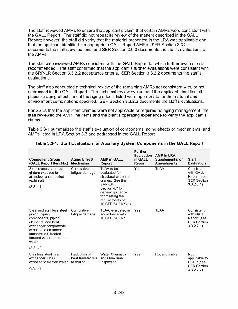
3-248
The staff reviewed AMRs to ensure the applicant’s claim that certain AMRs were consistent with the GALL Report. The staff did not repeat its review of the matters described in the GALL Report; however, the staff did verify that the material presented in the LRA was applicable and that the applicant identified the appropriate GALL Report AMRs. SER Section 3.3.2.1 documents the staff’s evaluations, and SER Section 3.0.3 documents the staff’s evaluations of the AMPs.
The staff also reviewed AMRs consistent with the GALL Report for which further evaluation is recommended. The staff confirmed that the applicant’s further evaluations were consistent with the SRP-LR Section 3.3.2.2 acceptance criteria. SER Section 3.3.2.2 documents the staff’s evaluations.
The staff also conducted a technical review of the remaining AMRs not consistent with, or not addressed in, the GALL Report. The technical review evaluated if the applicant identified all plausible aging effects and if the aging effects listed were appropriate for the material and environment combinations specified. SER Section 3.3.2.3 documents the staff’s evaluations.
For SSCs that the applicant claimed were not applicable or required no aging management, the staff reviewed the AMR line items and the plant’s operating experience to verify the applicant’s claims.
Table 3.3-1 summarizes the staff’s evaluation of components, aging effects or mechanisms, and AMPs listed in LRA Section 3.3 and addressed in the GALL Report.
Table 3.3-1. Staff Evaluation for Auxiliary System Components in the GALL Report
Component Group (GALL Report Item No.)
Aging Effect/ Mechanism
AMP in GALL Report
Further Evaluation in GALL Report
AMP in LRA, Supplements, or Amendments
Staff Evaluation
Steel cranes-structural girders exposed to air-indoor uncontrolled (external)
(3.3.1-1)
Cumulative fatigue damage
TLAA to be evaluated for structural girders of cranes. See the SRP-LR, Section 4.7 for generic guidance for meeting the requirements of 10 CFR 54.21(c)(1).
Yes TLAA Consistent with GALL Report (see SER Section 3.3.2.2.1)
Steel and stainless steel piping, piping components, piping elements, and heat exchanger components exposed to air-indoor uncontrolled, treated borated water or treated water
(3.3.1-2)
Cumulative fatigue damage
TLAA, evaluated in accordance with 10 CFR 54.21(c)
Yes TLAA Consistent with GALL Report (see SER Section 3.3.2.2.1)
Stainless steel heat exchanger tubes exposed to treated water
(3.3.1-3)
Reduction of heat transfer due to fouling
Water Chemistry and One-Time Inspection
Yes Not applicable Not applicable to DCPP (see SER Section 3.3.2.2.2)
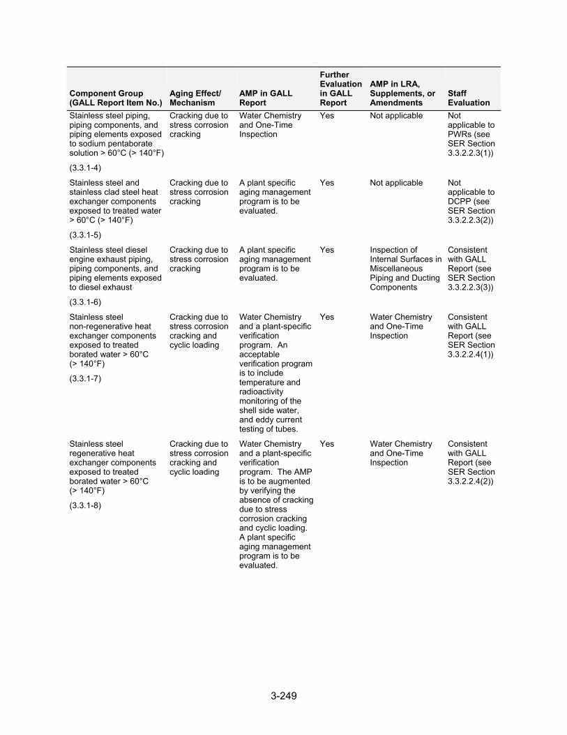
3-249
Component Group (GALL Report Item No.)
Aging Effect/ Mechanism
AMP in GALL Report
Further Evaluation in GALL Report
AMP in LRA, Supplements, or Amendments
Staff Evaluation
Stainless steel piping, piping components, and piping elements exposed to sodium pentaborate solution > 60°C (> 140°F)
(3.3.1-4)
Cracking due to stress corrosion cracking
Water Chemistry and One-Time Inspection
Yes Not applicable Not applicable to PWRs (see SER Section 3.3.2.2.3(1))
Stainless steel and stainless clad steel heat exchanger components exposed to treated water > 60°C (> 140°F)
(3.3.1-5)
Cracking due to stress corrosion cracking
A plant specific aging management program is to be evaluated.
Yes Not applicable Not applicable to DCPP (see SER Section 3.3.2.2.3(2))
Stainless steel diesel engine exhaust piping, piping components, and piping elements exposed to diesel exhaust
(3.3.1-6)
Cracking due to stress corrosion cracking
A plant specific aging management program is to be evaluated.
Yes Inspection of Internal Surfaces in Miscellaneous Piping and Ducting Components
Consistent with GALL Report (see SER Section 3.3.2.2.3(3))
Stainless steel non-regenerative heat exchanger components exposed to treated borated water > 60°C (> 140°F)
(3.3.1-7)
Cracking due to stress corrosion cracking and cyclic loading
Water Chemistry and a plant-specific verification program. An acceptable verification program is to include temperature and radioactivity monitoring of the shell side water, and eddy current testing of tubes.
Yes Water Chemistry and One-Time Inspection
Consistent with GALL Report (see SER Section 3.3.2.2.4(1))
Stainless steel regenerative heat exchanger components exposed to treated borated water > 60°C (> 140°F)
(3.3.1-8)
Cracking due to stress corrosion cracking and cyclic loading
Water Chemistry and a plant-specific verification program. The AMP is to be augmented by verifying the absence of cracking due to stress corrosion cracking and cyclic loading. A plant specific aging management program is to be evaluated.
Yes Water Chemistry and One-Time Inspection
Consistent with GALL Report (see SER Section 3.3.2.2.4(2))
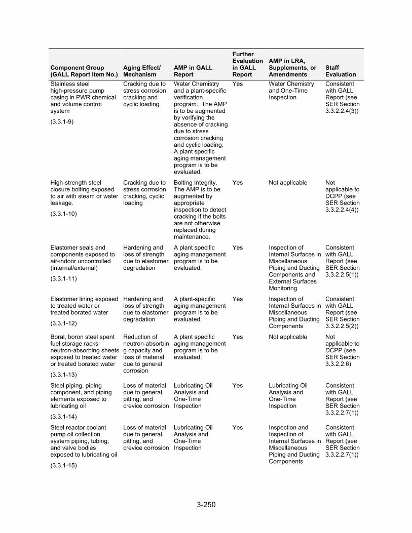
3-250
Component Group (GALL Report Item No.)
Aging Effect/ Mechanism
AMP in GALL Report
Further Evaluation in GALL Report
AMP in LRA, Supplements, or Amendments
Staff Evaluation
Stainless steel high-pressure pump casing in PWR chemical and volume control system
(3.3.1-9)
Cracking due to stress corrosion cracking and cyclic loading
Water Chemistry and a plant-specific verification program. The AMP is to be augmented by verifying the absence of cracking due to stress corrosion cracking and cyclic loading. A plant specific aging management program is to be evaluated.
Yes Water Chemistry and One-Time Inspection
Consistent with GALL Report (see SER Section 3.3.2.2.4(3))
High-strength steel closure bolting exposed to air with steam or water leakage.
(3.3.1-10)
Cracking due to stress corrosion cracking, cyclic loading
Bolting Integrity. The AMP is to be augmented by appropriate inspection to detect cracking if the bolts are not otherwise replaced during maintenance.
Yes Not applicable Not applicable to DCPP (see SER Section 3.3.2.2.4(4))
Elastomer seals and components exposed to air-indoor uncontrolled (internal/external)
(3.3.1-11)
Hardening and loss of strength due to elastomer degradation
A plant specific aging management program is to be evaluated.
Yes Inspection of Internal Surfaces in Miscellaneous Piping and Ducting Components and External Surfaces Monitoring
Consistent with GALL Report (see SER Section 3.3.2.2.5(1))
Elastomer lining exposed to treated water or treated borated water
(3.3.1-12)
Hardening and loss of strength due to elastomer degradation
A plant-specific aging management program is to be evaluated.
Yes Inspection of Internal Surfaces in Miscellaneous Piping and Ducting Components
Consistent with GALL Report (see SER Section 3.3.2.2.5(2))
Boral, boron steel spent fuel storage racks neutron-absorbing sheets exposed to treated water or treated borated water
(3.3.1-13)
Reduction of neutron-absorbing capacity and loss of material due to general corrosion
A plant specific aging management program is to be evaluated.
Yes Not applicable Not applicable to DCPP (see SER Section 3.3.2.2.6)
Steel piping, piping component, and piping elements exposed to lubricating oil
(3.3.1-14)
Loss of material due to general, pitting, and crevice corrosion
Lubricating Oil Analysis and One-Time Inspection
Yes Lubricating Oil Analysis and One-Time Inspection
Consistent with GALL Report (see SER Section 3.3.2.2.7(1))
Steel reactor coolant pump oil collection system piping, tubing, and valve bodies exposed to lubricating oil
(3.3.1-15)
Loss of material due to general, pitting, and crevice corrosion
Lubricating Oil Analysis and One-Time Inspection
Yes Inspection and Inspection of Internal Surfaces in Miscellaneous Piping and Ducting Components
Consistent with GALL Report (see SER Section 3.3.2.2.7(1))
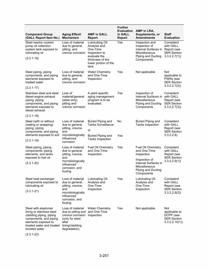
3-251
Component Group (GALL Report Item No.)
Aging Effect/ Mechanism
AMP in GALL Report
Further Evaluation in GALL Report
AMP in LRA, Supplements, or Amendments
Staff Evaluation
Steel reactor coolant pump oil collection system tank exposed to lubricating oil
(3.3.1-16)
Loss of material due to general, pitting, and crevice corrosion
Lubricating Oil Analysis and One-Time Inspection to evaluate the thickness of the lower portion of the tank
Yes Inspection and Inspection of Internal Surfaces in Miscellaneous Piping and Ducting Components
Consistent with GALL Report (see SER Section 3.3.2.2.7(1))
Steel piping, piping components, and piping elements exposed to treated water
(3.3.1-17)
Loss of material due to general, pitting, and crevice corrosion
Water Chemistry and One-Time Inspection
Yes Not applicable Not applicable to PWRs (see SER Section 3.3.2.2.7(2))
Stainless steel and steel diesel engine exhaust piping, piping components, and piping elements exposed to diesel exhaust
(3.3.1-18)
Loss of material/general (steel only), pitting and crevice corrosion
A plant specific aging management program is to be evaluated.
Yes Inspection of Internal Surfaces in Miscellaneous Piping and Ducting Components
Consistent with GALL Report (see SER Section 3.3.2.2.7(3))
Steel (with or without coating or wrapping) piping, piping components, and piping elements exposed to soil
(3.3.1-19)
Loss of material due to general, pitting, crevice, and microbiologically influenced corrosion
Buried Piping and Tanks Surveillance
or
Buried Piping and Tanks Inspection
No
Yes
Buried Piping and Tanks Inspection
Consistent with GALL Report (see SER Section 3.3.2.2.8)
Steel piping, piping components, piping elements, and tanks exposed to fuel oil
(3.3.1-20)
Loss of material due to general, pitting, crevice, and microbiologically influenced corrosion, and fouling
Fuel Oil Chemistry and One-Time Inspection
Yes Fuel Oil Chemistry and One-Time Inspection
Inspection of Internal Surfaces in Miscellaneous Piping and Ducting Components
Consistent with GALL Report (see SER Section 3.3.2.2.9(1))
Steel heat exchanger components exposed to lubricating oil
(3.3.1-21)
Loss of material due to general, pitting, crevice, and microbiologically influenced corrosion, and fouling
Lubricating Oil Analysis and One-Time Inspection
Yes Lubricating Oil Analysis and One-Time Inspection
Consistentwith GALL Report (see SER Section 3.3.2.2.9(2))
Steel with elastomer lining or stainless steel cladding piping, piping components, and piping elements exposed to treated water and treated borated water
(3.3.1-22)
Loss of material due to pitting and crevice corrosion (only for steel after lining/cladding degradation)
Water Chemistry and One-Time Inspection
Yes Not applicable Not applicable to DCPP (see SER Section 3.3.2.2.10(1))
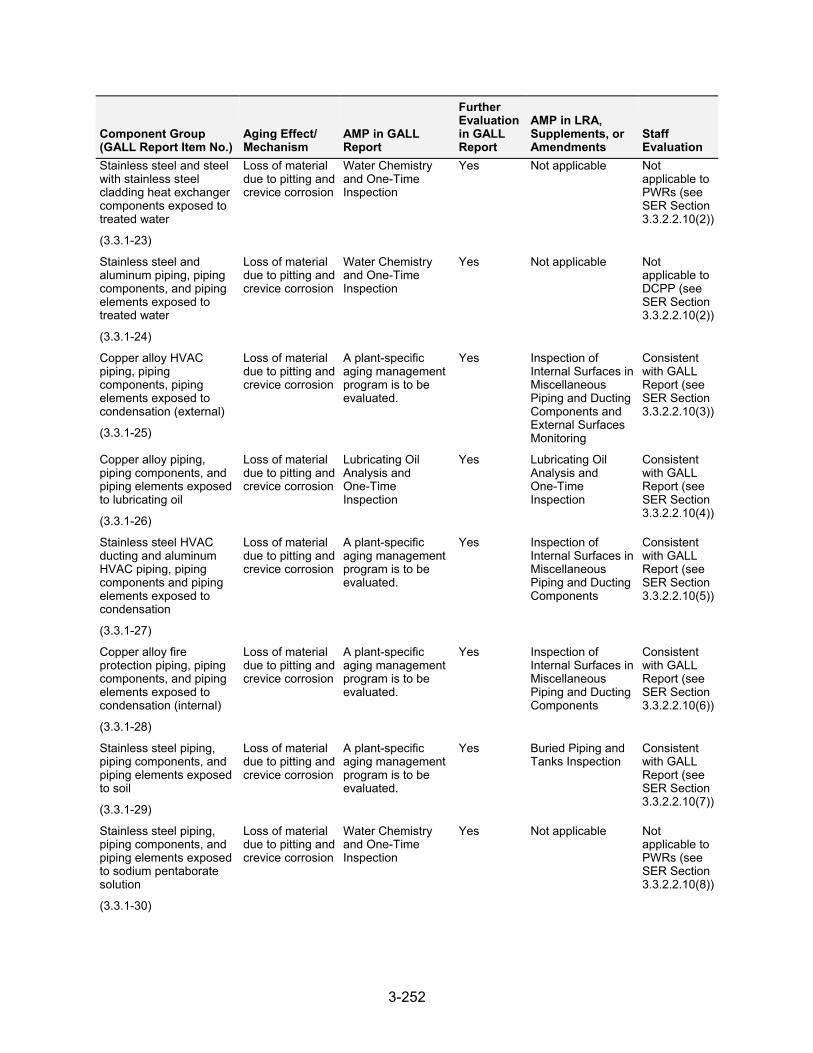
3-252
Component Group (GALL Report Item No.)
Aging Effect/ Mechanism
AMP in GALL Report
Further Evaluation in GALL Report
AMP in LRA, Supplements, or Amendments
Staff Evaluation
Stainless steel and steel with stainless steel cladding heat exchanger components exposed to treated water
(3.3.1-23)
Loss of material due to pitting and crevice corrosion
Water Chemistry and One-Time Inspection
Yes Not applicable Not applicable to PWRs (see SER Section 3.3.2.2.10(2))
Stainless steel and aluminum piping, piping components, and piping elements exposed to treated water
(3.3.1-24)
Loss of material due to pitting and crevice corrosion
Water Chemistry and One-Time Inspection
Yes Not applicable Not applicable to DCPP (see SER Section 3.3.2.2.10(2))
Copper alloy HVAC piping, piping components, piping elements exposed to condensation (external)
(3.3.1-25)
Loss of material due to pitting and crevice corrosion
A plant-specific aging management program is to be evaluated.
Yes Inspection of Internal Surfaces in Miscellaneous Piping and Ducting Components and External Surfaces Monitoring
Consistent with GALL Report (see SER Section 3.3.2.2.10(3))
Copper alloy piping, piping components, and piping elements exposed to lubricating oil
(3.3.1-26)
Loss of material due to pitting and crevice corrosion
Lubricating Oil Analysis and One-Time Inspection
Yes Lubricating Oil Analysis and One-Time Inspection
Consistent with GALL Report (see SER Section 3.3.2.2.10(4))
Stainless steel HVAC ducting and aluminum HVAC piping, piping components and piping elements exposed to condensation
(3.3.1-27)
Loss of material due to pitting and crevice corrosion
A plant-specific aging management program is to be evaluated.
Yes Inspection of Internal Surfaces in Miscellaneous Piping and Ducting Components
Consistent with GALL Report (see SER Section 3.3.2.2.10(5))
Copper alloy fire protection piping, piping components, and piping elements exposed to condensation (internal)
(3.3.1-28)
Loss of material due to pitting and crevice corrosion
A plant-specific aging management program is to be evaluated.
Yes Inspection of Internal Surfaces in Miscellaneous Piping and Ducting Components
Consistent with GALL Report (see SER Section 3.3.2.2.10(6))
Stainless steel piping, piping components, and piping elements exposed to soil
(3.3.1-29)
Loss of material due to pitting and crevice corrosion
A plant-specific aging management program is to be evaluated.
Yes Buried Piping and Tanks Inspection
Consistent with GALL Report (see SER Section 3.3.2.2.10(7))
Stainless steel piping, piping components, and piping elements exposed to sodium pentaborate solution
(3.3.1-30)
Loss of material due to pitting and crevice corrosion
Water Chemistry and One-Time Inspection
Yes Not applicable Not applicable to PWRs (see SER Section 3.3.2.2.10(8))
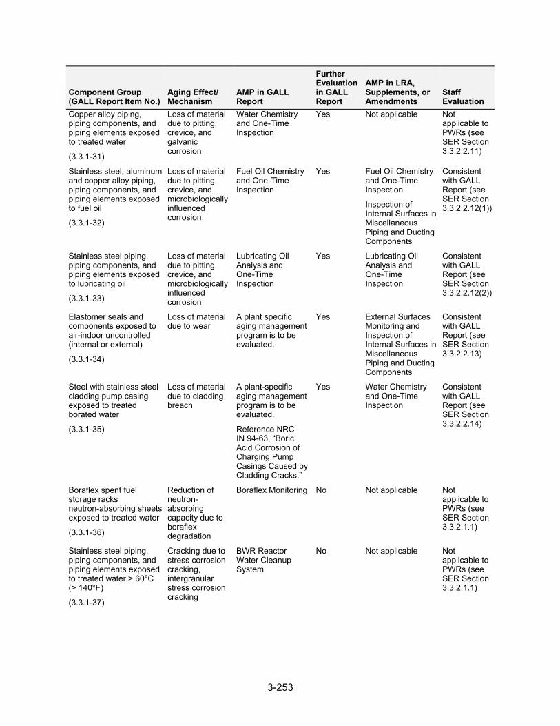
3-253
Component Group (GALL Report Item No.)
Aging Effect/ Mechanism
AMP in GALL Report
Further Evaluation in GALL Report
AMP in LRA, Supplements, or Amendments
Staff Evaluation
Copper alloy piping, piping components, and piping elements exposed to treated water
(3.3.1-31)
Loss of material due to pitting, crevice, and galvanic corrosion
Water Chemistry and One-Time Inspection
Yes Not applicable Not applicable to PWRs (see SER Section 3.3.2.2.11)
Stainless steel, aluminum and copper alloy piping, piping components, and piping elements exposed to fuel oil
(3.3.1-32)
Loss of material due to pitting, crevice, and microbiologically influenced corrosion
Fuel Oil Chemistry and One-Time Inspection
Yes Fuel Oil Chemistry and One-Time Inspection
Inspection of Internal Surfaces in Miscellaneous Piping and Ducting Components
Consistent with GALL Report (see SER Section 3.3.2.2.12(1))
Stainless steel piping, piping components, and piping elements exposed to lubricating oil
(3.3.1-33)
Loss of material due to pitting, crevice, and microbiologically influenced corrosion
Lubricating Oil Analysis and One-Time Inspection
Yes Lubricating Oil Analysis and One-Time Inspection
Consistent with GALL Report (see SER Section 3.3.2.2.12(2))
Elastomer seals and components exposed to air-indoor uncontrolled (internal or external)
(3.3.1-34)
Loss of material due to wear
A plant specific aging management program is to be evaluated.
Yes External Surfaces Monitoring and Inspection of Internal Surfaces in Miscellaneous Piping and Ducting Components
Consistent with GALL Report (see SER Section 3.3.2.2.13)
Steel with stainless steel cladding pump casing exposed to treated borated water
(3.3.1-35)
Loss of materialdue to cladding breach
A plant-specific aging management program is to be evaluated.
Reference NRC IN 94-63, “Boric Acid Corrosion of Charging Pump Casings Caused by Cladding Cracks.”
Yes Water Chemistry and One-Time Inspection
Consistent with GALL Report (see SER Section 3.3.2.2.14)
Boraflex spent fuel storage racks neutron-absorbing sheets exposed to treated water
(3.3.1-36)
Reduction of neutron- absorbing capacity due to boraflex degradation
Boraflex Monitoring No Not applicable Not applicable to PWRs (see SER Section 3.3.2.1.1)
Stainless steel piping, piping components, and piping elements exposed to treated water > 60°C (> 140°F)
(3.3.1-37)
Cracking due to stress corrosion cracking, intergranular stress corrosion cracking
BWR Reactor Water Cleanup System
No Not applicable Not applicable to PWRs (see SER Section 3.3.2.1.1)
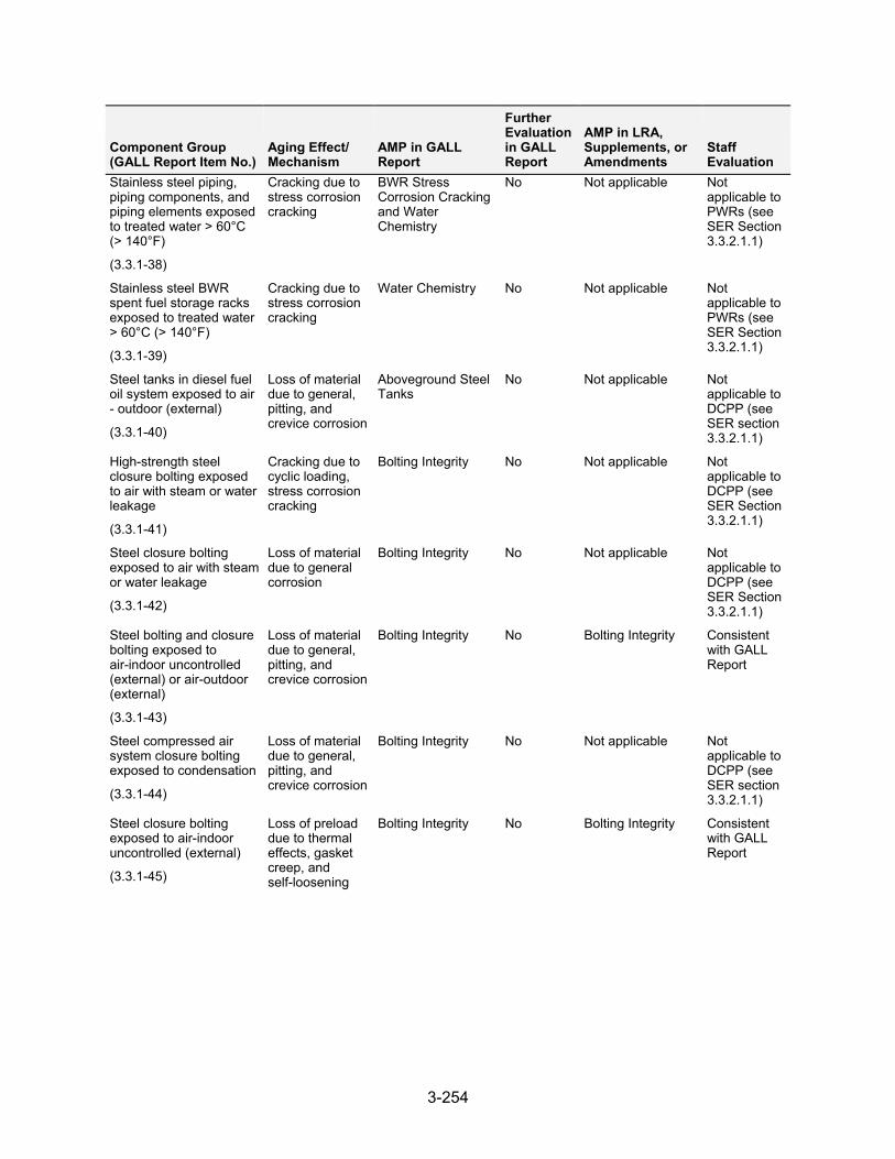
3-254
Component Group (GALL Report Item No.)
Aging Effect/ Mechanism
AMP in GALL Report
Further Evaluation in GALL Report
AMP in LRA, Supplements, or Amendments
Staff Evaluation
Stainless steel piping, piping components, and piping elements exposed to treated water > 60°C (> 140°F)
(3.3.1-38)
Cracking due to stress corrosion cracking
BWR Stress Corrosion Cracking and Water Chemistry
No Not applicable Not applicable to PWRs (see SER Section 3.3.2.1.1)
Stainless steel BWR spent fuel storage racks exposed to treated water > 60°C (> 140°F)
(3.3.1-39)
Cracking due to stress corrosion cracking
Water Chemistry No Not applicable Not applicable to PWRs (see SER Section 3.3.2.1.1)
Steel tanks in diesel fuel oil system exposed to air - outdoor (external)
(3.3.1-40)
Loss of material due to general, pitting, and crevice corrosion
Aboveground Steel Tanks
No Not applicable Not applicable to DCPP (see SER section 3.3.2.1.1)
High-strength steel closure bolting exposed to air with steam or water leakage
(3.3.1-41)
Cracking due to cyclic loading, stress corrosion cracking
Bolting Integrity No Not applicable Not applicable to DCPP (see SER Section 3.3.2.1.1)
Steel closure bolting exposed to air with steam or water leakage
(3.3.1-42)
Loss of material due to general corrosion
Bolting Integrity No Not applicable Not applicable to DCPP (see SER Section 3.3.2.1.1)
Steel bolting and closure bolting exposed to air-indoor uncontrolled (external) or air-outdoor (external)
(3.3.1-43)
Loss of material due to general, pitting, and crevice corrosion
Bolting Integrity No Bolting Integrity Consistent with GALL Report
Steel compressed air system closure bolting exposed to condensation
(3.3.1-44)
Loss of material due to general, pitting, and crevice corrosion
Bolting Integrity No Not applicable Not applicable to DCPP (see SER section 3.3.2.1.1)
Steel closure bolting exposed to air-indoor uncontrolled (external)
(3.3.1-45)
Loss of preload due to thermal effects, gasket creep, and self-loosening
Bolting Integrity No Bolting Integrity Consistent with GALL Report
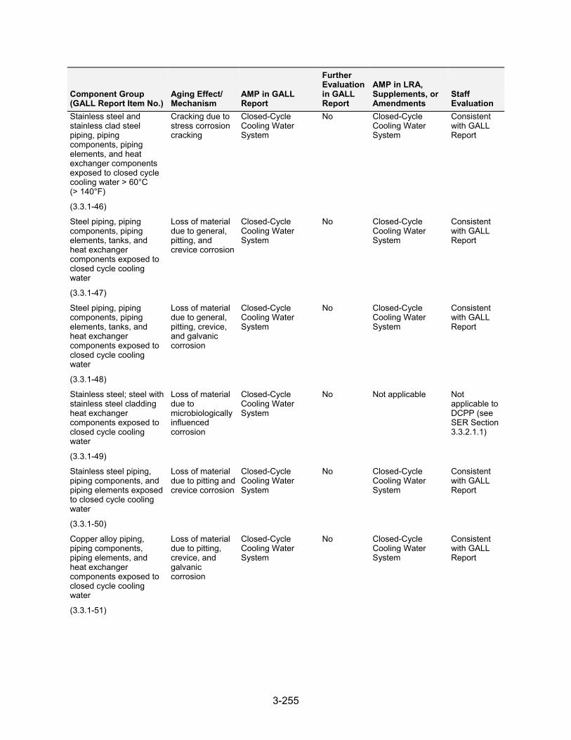
3-255
Component Group (GALL Report Item No.)
Aging Effect/ Mechanism
AMP in GALL Report
Further Evaluation in GALL Report
AMP in LRA, Supplements, or Amendments
Staff Evaluation
Stainless steel and stainless clad steel piping, piping components, piping elements, and heat exchanger components exposed to closed cycle cooling water > 60°C (> 140°F)
(3.3.1-46)
Cracking due to stress corrosion cracking
Closed-Cycle Cooling Water System
No Closed-Cycle Cooling Water System
Consistent with GALL Report
Steel piping, piping components, piping elements, tanks, and heat exchanger components exposed to closed cycle cooling water
(3.3.1-47)
Loss of material due to general, pitting, and crevice corrosion
Closed-Cycle Cooling Water System
No Closed-Cycle Cooling Water System
Consistent with GALL Report
Steel piping, piping components, piping elements, tanks, and heat exchanger components exposed to closed cycle cooling water
(3.3.1-48)
Loss of material due to general, pitting, crevice, and galvanic corrosion
Closed-Cycle Cooling Water System
No Closed-Cycle Cooling Water System
Consistent with GALL Report
Stainless steel; steel with stainless steel cladding heat exchanger components exposed to closed cycle cooling water
(3.3.1-49)
Loss of material due to microbiologically influenced corrosion
Closed-Cycle Cooling Water System
No Not applicable Not applicable to DCPP (see SER Section 3.3.2.1.1)
Stainless steel piping, piping components, and piping elements exposed to closed cycle cooling water
(3.3.1-50)
Loss of material due to pitting and crevice corrosion
Closed-Cycle Cooling Water System
No Closed-Cycle Cooling Water System
Consistent with GALL Report
Copper alloy piping, piping components, piping elements, and heat exchanger components exposed to closed cycle cooling water
(3.3.1-51)
Loss of material due to pitting, crevice, and galvanic corrosion
Closed-Cycle Cooling Water System
No Closed-Cycle Cooling Water System
Consistent with GALL Report
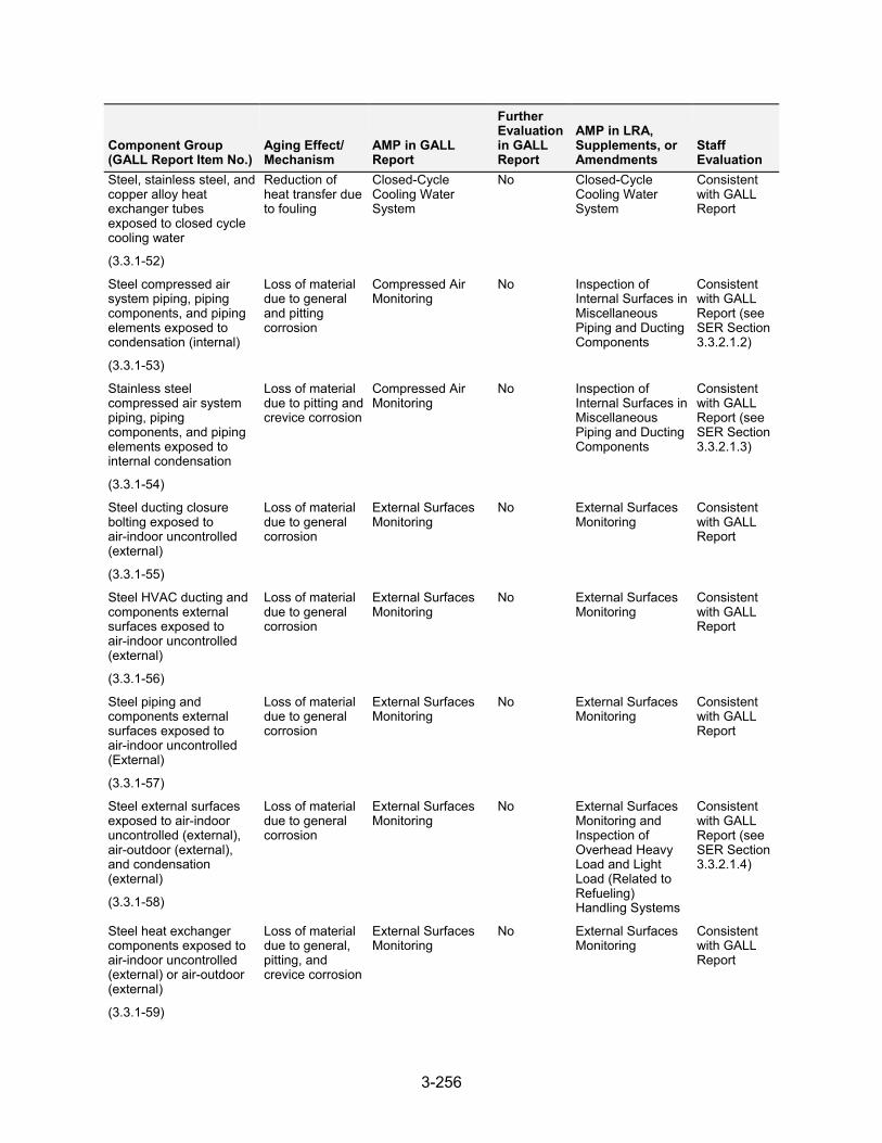
3-256
Component Group (GALL Report Item No.)
Aging Effect/ Mechanism
AMP in GALL Report
Further Evaluation in GALL Report
AMP in LRA, Supplements, or Amendments
Staff Evaluation
Steel, stainless steel, and copper alloy heat exchanger tubes exposed to closed cycle cooling water
(3.3.1-52)
Reduction of heat transfer due to fouling
Closed-Cycle Cooling Water System
No Closed-Cycle Cooling Water System
Consistent with GALL Report
Steel compressed air system piping, piping components, and piping elements exposed to condensation (internal)
(3.3.1-53)
Loss of material due to general and pitting corrosion
Compressed Air Monitoring
No Inspection of Internal Surfaces in Miscellaneous Piping and Ducting Components
Consistent with GALL Report (see SER Section 3.3.2.1.2)
Stainless steel compressed air system piping, piping components, and piping elements exposed to internal condensation
(3.3.1-54)
Loss of material due to pitting and crevice corrosion
Compressed Air Monitoring
No Inspection of Internal Surfaces in Miscellaneous Piping and Ducting Components
Consistent with GALL Report (see SER Section 3.3.2.1.3)
Steel ducting closure bolting exposed to air-indoor uncontrolled (external)
(3.3.1-55)
Loss of material due to general corrosion
External Surfaces Monitoring
No External Surfaces Monitoring
Consistent with GALL Report
Steel HVAC ducting and components external surfaces exposed to air-indoor uncontrolled (external)
(3.3.1-56)
Loss of material due to general corrosion
External Surfaces Monitoring
No External Surfaces Monitoring
Consistent with GALL Report
Steel piping and components external surfaces exposed to air-indoor uncontrolled (External)
(3.3.1-57)
Loss of material due to general corrosion
External Surfaces Monitoring
No External Surfaces Monitoring
Consistentwith GALL Report
Steel external surfaces exposed to air-indoor uncontrolled (external), air-outdoor (external), and condensation (external)
(3.3.1-58)
Loss of material due to general corrosion
External Surfaces Monitoring
No External Surfaces Monitoring and Inspection of Overhead Heavy Load and Light Load (Related to Refueling) Handling Systems
Consistent with GALL Report (see SER Section 3.3.2.1.4)
Steel heat exchanger components exposed to air-indoor uncontrolled (external) or air-outdoor (external)
(3.3.1-59)
Loss of material due to general, pitting, and crevice corrosion
External Surfaces Monitoring
No External Surfaces Monitoring
Consistent with GALL Report
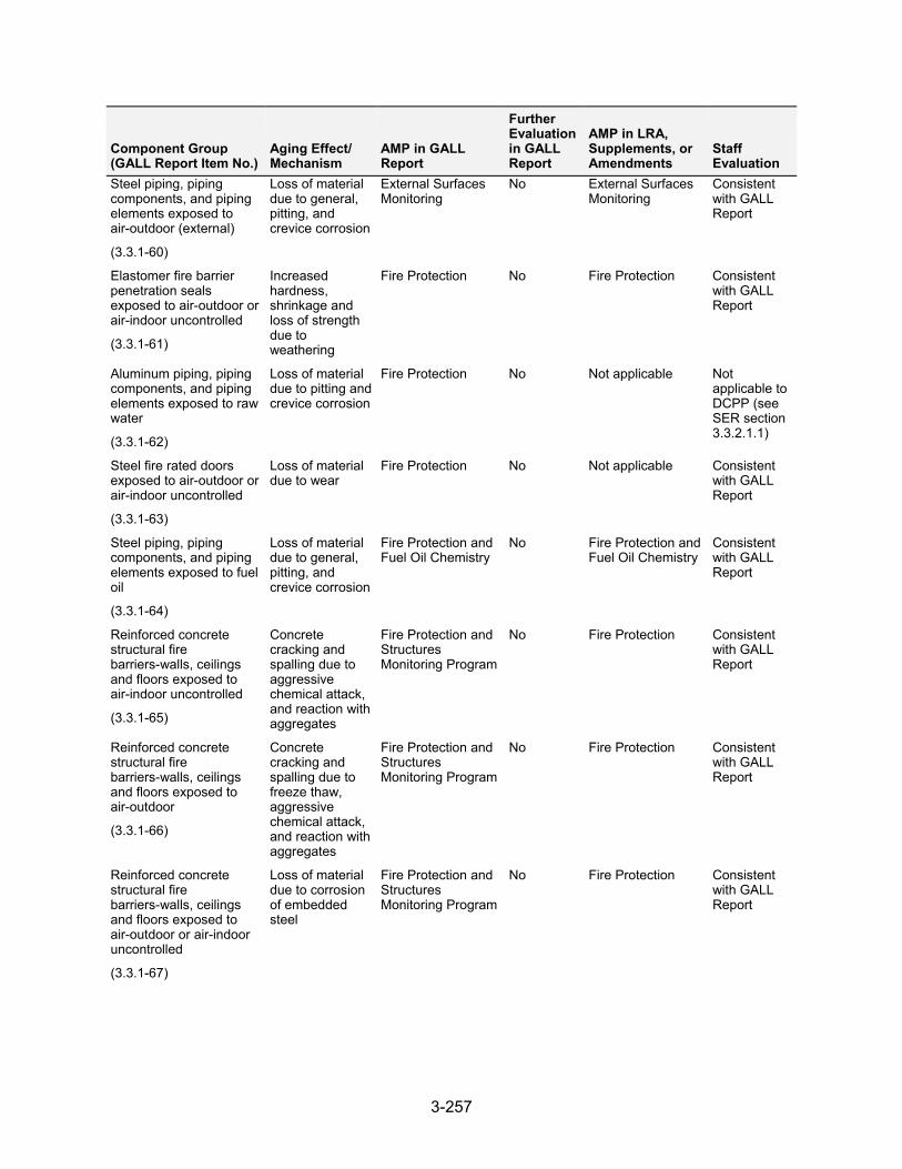
3-257
Component Group (GALL Report Item No.)
Aging Effect/ Mechanism
AMP in GALL Report
Further Evaluation in GALL Report
AMP in LRA, Supplements, or Amendments
Staff Evaluation
Steel piping, piping components, and piping elements exposed to air-outdoor (external)
(3.3.1-60)
Loss of material due to general, pitting, and crevice corrosion
External Surfaces Monitoring
No External Surfaces Monitoring
Consistent with GALL Report
Elastomer fire barrier penetration seals exposed to air-outdoor or air-indoor uncontrolled
(3.3.1-61)
Increased hardness, shrinkage and loss of strength due to weathering
Fire Protection No Fire Protection Consistent with GALL Report
Aluminum piping, piping components, and piping elements exposed to raw water
(3.3.1-62)
Loss of material due to pitting and crevice corrosion
Fire Protection No Not applicable Not applicable to DCPP (see SER section 3.3.2.1.1)
Steel fire rated doors exposed to air-outdoor or air-indoor uncontrolled
(3.3.1-63)
Loss of material due to wear
Fire Protection No Not applicable Consistent with GALL Report
Steel piping, piping components, and piping elements exposed to fuel oil
(3.3.1-64)
Loss of material due to general, pitting, and crevice corrosion
Fire Protection and Fuel Oil Chemistry
No Fire Protection and Fuel Oil Chemistry
Consistent with GALL Report
Reinforced concrete structural fire barriers-walls, ceilings and floors exposed to air-indoor uncontrolled
(3.3.1-65)
Concrete cracking and spalling due to aggressive chemical attack, and reaction with aggregates
Fire Protection and Structures Monitoring Program
No Fire Protection Consistent with GALL Report
Reinforced concrete structural fire barriers-walls, ceilings and floors exposed to air-outdoor
(3.3.1-66)
Concrete cracking and spalling due to freeze thaw, aggressive chemical attack, and reaction with aggregates
Fire Protection and Structures Monitoring Program
No Fire Protection Consistent with GALL Report
Reinforced concrete structural fire barriers-walls, ceilings and floors exposed to air-outdoor or air-indoor uncontrolled
(3.3.1-67)
Loss of material due to corrosion of embedded steel
Fire Protection and Structures Monitoring Program
No Fire Protection Consistent with GALL Report
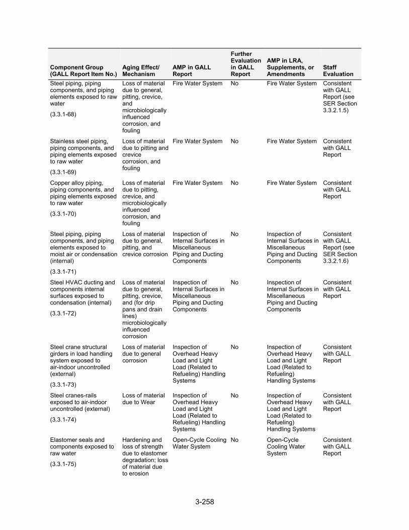
3-258
Component Group (GALL Report Item No.)
Aging Effect/ Mechanism
AMP in GALL Report
Further Evaluation in GALL Report
AMP in LRA, Supplements, or Amendments
Staff Evaluation
Steel piping, piping components, and piping elements exposed to raw water
(3.3.1-68)
Loss of material due to general, pitting, crevice, and microbiologically influenced corrosion, and fouling
Fire Water System No Fire Water System Consistent with GALL Report (see SER Section 3.3.2.1.5)
Stainless steel piping, piping components, and piping elements exposed to raw water
(3.3.1-69)
Loss of material due to pitting and crevice corrosion, and fouling
Fire Water System No Fire Water System Consistent with GALL Report
Copper alloy piping, piping components, and piping elements exposed to raw water
(3.3.1-70)
Loss of material due to pitting, crevice, and microbiologically influenced corrosion, and fouling
Fire Water System No Fire Water System Consistent with GALL Report
Steel piping, piping components, and piping elements exposed to moist air or condensation (internal)
(3.3.1-71)
Loss of material due to general, pitting, and crevice corrosion
Inspection of Internal Surfaces in Miscellaneous Piping and Ducting Components
No Inspection of Internal Surfaces in Miscellaneous Piping and Ducting Components
Consistent with GALL Report (see SER Section 3.3.2.1.6)
Steel HVAC ducting and components internal surfaces exposed to condensation (internal)
(3.3.1-72)
Loss of material due to general, pitting, crevice, and (for drip pans and drain lines) microbiologically influenced corrosion
Inspection of Internal Surfaces in Miscellaneous Piping and Ducting Components
No Inspection of Internal Surfaces in Miscellaneous Piping and Ducting Components
Consistent with GALL Report
Steel crane structural girders in load handling system exposed to air-indoor uncontrolled (external)
(3.3.1-73)
Loss of material due to general corrosion
Inspection of Overhead Heavy Load and Light Load (Related to Refueling) Handling Systems
No Inspection of Overhead Heavy Load and Light Load (Related to Refueling) Handling Systems
Consistent with GALL Report
Steel cranes-rails exposed to air-indoor uncontrolled (external)
(3.3.1-74)
Loss of material due to Wear
Inspection of Overhead Heavy Load and Light Load (Related to Refueling) Handling Systems
No Inspection of Overhead Heavy Load and Light Load (Related to Refueling) Handling Systems
Consistent with GALL Report
Elastomer seals and components exposed to raw water
(3.3.1-75)
Hardening and loss of strength due to elastomer degradation; loss of material due to erosion
Open-Cycle Cooling Water System
No Open-Cycle Cooling Water System
Consistent with GALL Report
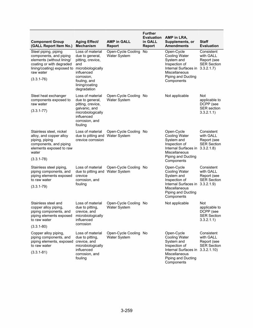
3-259
Component Group (GALL Report Item No.)
Aging Effect/ Mechanism
AMP in GALL Report
Further Evaluation in GALL Report
AMP in LRA, Supplements, or Amendments
Staff Evaluation
Steel piping, piping components, and piping elements (without lining/ coating or with degraded lining/coating) exposed to raw water
(3.3.1-76)
Loss of material due to general, pitting, crevice, and microbiologically influenced corrosion, fouling, and lining/coating degradation
Open-Cycle Cooling Water System
No Open-Cycle Cooling Water System and Inspection of Internal Surfaces in Miscellaneous Piping and Ducting Components
Consistent with GALL Report (see SER Section 3.3.2.1.7)
Steel heat exchanger components exposed to raw water
(3.3.1-77)
Loss of material due to general, pitting, crevice, galvanic, and microbiologically influenced corrosion, and fouling
Open-Cycle Cooling Water System
No Not applicable Not applicable to DCPP (see SER section 3.3.2.1.1)
Stainless steel, nickel alloy, and copper alloy piping, piping components, and piping elements exposed to raw water
(3.3.1-78)
Loss of material due to pitting and crevice corrosion
Open-Cycle Cooling Water System
No Open-Cycle Cooling Water System and Inspection of Internal Surfaces in Miscellaneous Piping and Ducting Components
Consistent with GALL Report (see SER Section 3.3.2.1.8)
Stainless steel piping, piping components, and piping elements exposed to raw water
(3.3.1-79)
Loss of material due to pitting and crevice corrosion, and fouling
Open-Cycle Cooling Water System
No Open-Cycle Cooling Water System and Inspection of Internal Surfaces in Miscellaneous Piping and Ducting Components
Consistent with GALL Report (see SER Section 3.3.2.1.9)
Stainless steel and copper alloy piping, piping components, and piping elements exposed to raw water
(3.3.1-80)
Loss of material due to pitting, crevice, and microbiologically influenced corrosion
Open-Cycle Cooling Water System
No Not applicable Not applicable to DCPP (see SER Section 3.3.2.1.1)
Copper alloy piping, piping components, and piping elements, exposed to raw water
(3.3.1-81)
Loss of material due to pitting, crevice, and microbiologically influenced corrosion, and fouling
Open-Cycle Cooling Water System
No Open-Cycle Cooling Water System and Inspection of Internal Surfaces in Miscellaneous Piping and Ducting Components
Consistent with GALL Report (see SER Section 3.3.2.1.10)
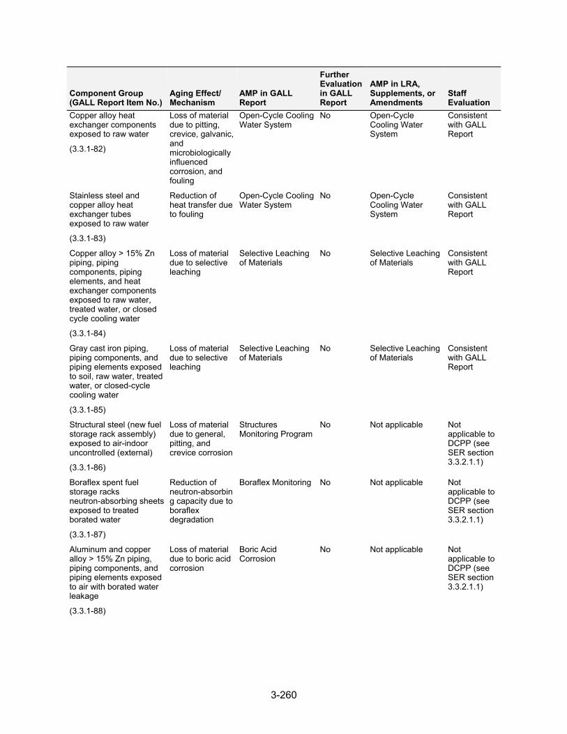
3-260
Component Group (GALL Report Item No.)
Aging Effect/ Mechanism
AMP in GALL Report
Further Evaluation in GALL Report
AMP in LRA, Supplements, or Amendments
Staff Evaluation
Copper alloy heat exchanger components exposed to raw water
(3.3.1-82)
Loss of material due to pitting, crevice, galvanic, and microbiologically influenced corrosion, and fouling
Open-Cycle Cooling Water System
No Open-Cycle Cooling Water System
Consistent with GALL Report
Stainless steel and copper alloy heat exchanger tubes exposed to raw water
(3.3.1-83)
Reduction of heat transfer due to fouling
Open-Cycle Cooling Water System
No Open-Cycle Cooling Water System
Consistent with GALL Report
Copper alloy > 15% Zn piping, piping components, piping elements, and heat exchanger components exposed to raw water, treated water, or closed cycle cooling water
(3.3.1-84)
Loss of material due to selective leaching
Selective Leaching of Materials
No Selective Leaching of Materials
Consistent with GALL Report
Gray cast iron piping, piping components, and piping elements exposed to soil, raw water, treated water, or closed-cycle cooling water
(3.3.1-85)
Loss of material due to selective leaching
Selective Leaching of Materials
No Selective Leaching of Materials
Consistent with GALL Report
Structural steel (new fuel storage rack assembly) exposed to air-indoor uncontrolled (external)
(3.3.1-86)
Loss of material due to general, pitting, and crevice corrosion
Structures Monitoring Program
No Not applicable Not applicable to DCPP (see SER section 3.3.2.1.1)
Boraflex spent fuel storage racks neutron-absorbing sheets exposed to treated borated water
(3.3.1-87)
Reduction of neutron-absorbing capacity due to boraflex degradation
Boraflex Monitoring No Not applicable Not applicable to DCPP (see SER section 3.3.2.1.1)
Aluminum and copper alloy > 15% Zn piping, piping components, and piping elements exposed to air with borated water leakage
(3.3.1-88)
Loss of material due to boric acid corrosion
Boric Acid Corrosion
No Not applicable Not applicable to DCPP (see SER section 3.3.2.1.1)
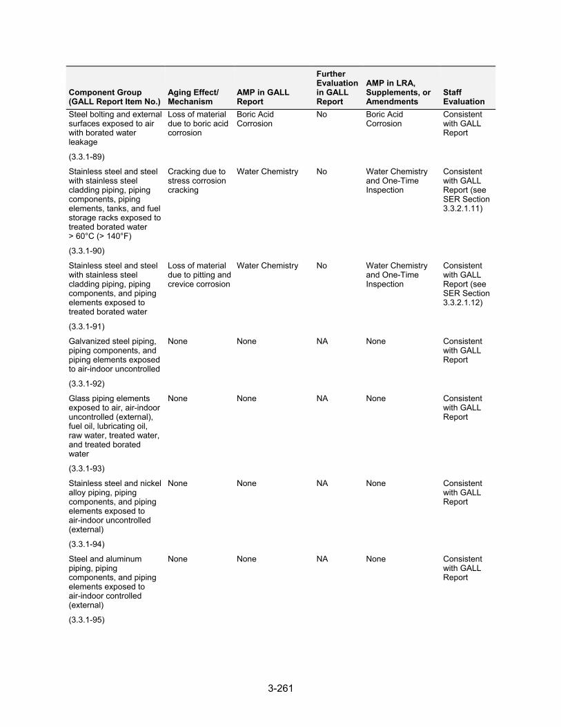
3-261
Component Group (GALL Report Item No.)
Aging Effect/ Mechanism
AMP in GALL Report
Further Evaluation in GALL Report
AMP in LRA, Supplements, or Amendments
Staff Evaluation
Steel bolting and external surfaces exposed to air with borated water leakage
(3.3.1-89)
Loss of material due to boric acid corrosion
Boric Acid Corrosion
No Boric Acid Corrosion
Consistent with GALL Report
Stainless steel and steel with stainless steel cladding piping, piping components, piping elements, tanks, and fuel storage racks exposed to treated borated water > 60°C (> 140°F)
(3.3.1-90)
Cracking due to stress corrosion cracking
Water Chemistry No Water Chemistry and One-Time Inspection
Consistent with GALL Report (see SER Section 3.3.2.1.11)
Stainless steel and steel with stainless steel cladding piping, piping components, and piping elements exposed to treated borated water
(3.3.1-91)
Loss of material due to pitting and crevice corrosion
Water Chemistry No Water Chemistry and One-Time Inspection
Consistent with GALL Report (see SER Section 3.3.2.1.12)
Galvanized steel piping, piping components, and piping elements exposed to air-indoor uncontrolled
(3.3.1-92)
None None NA None Consistent with GALL Report
Glass piping elements exposed to air, air-indoor uncontrolled (external), fuel oil, lubricating oil, raw water, treated water, and treated borated water
(3.3.1-93)
None None NA None Consistent with GALL Report
Stainless steel and nickel alloy piping, piping components, and piping elements exposed to air-indoor uncontrolled (external)
(3.3.1-94)
None None NA None Consistent with GALL Report
Steel and aluminum piping, piping components, and piping elements exposed to air-indoor controlled (external)
(3.3.1-95)
None None NA None Consistent with GALL Report
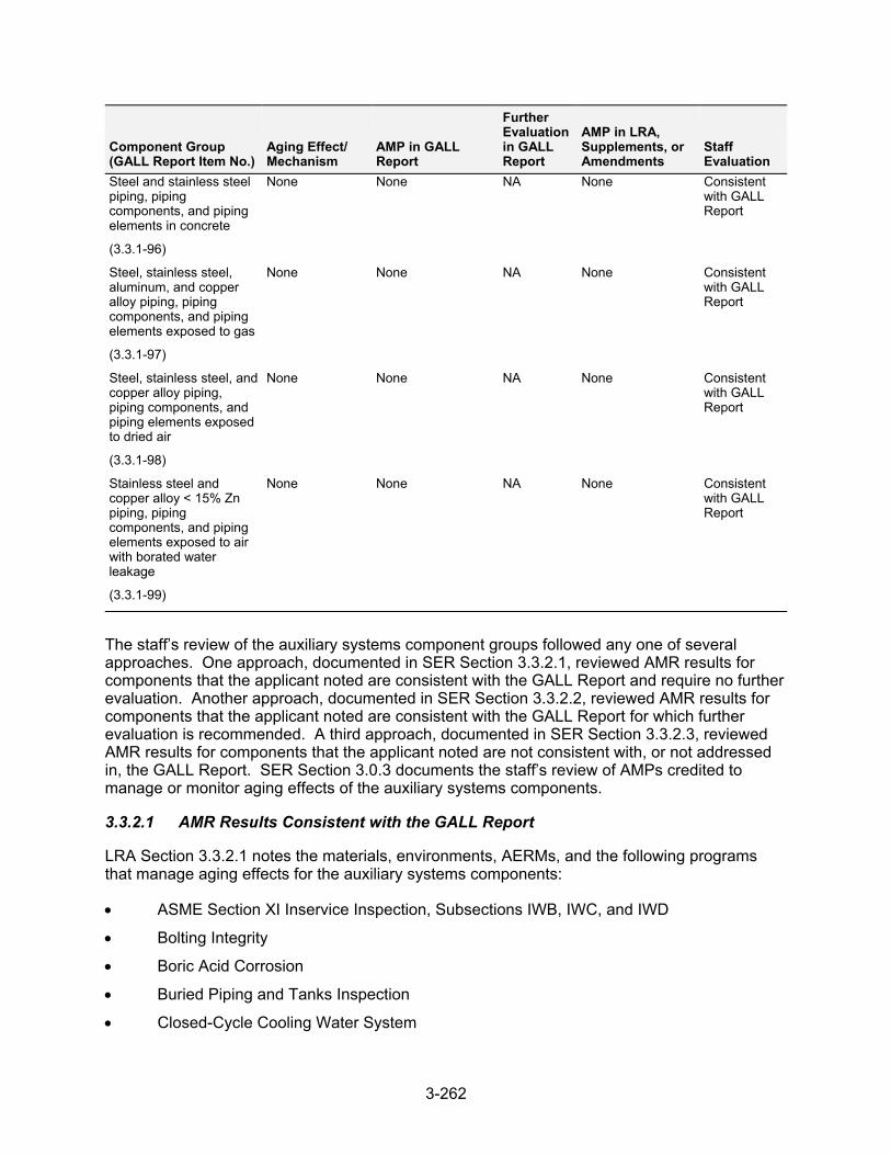
3-262
Component Group (GALL Report Item No.)
Aging Effect/ Mechanism
AMP in GALL Report
Further Evaluation in GALL Report
AMP in LRA, Supplements, or Amendments
Staff Evaluation
Steel and stainless steel piping, piping components, and piping elements in concrete
(3.3.1-96)
None None NA None Consistent with GALL Report
Steel, stainless steel, aluminum, and copper alloy piping, piping components, and piping elements exposed to gas
(3.3.1-97)
None None NA None Consistent with GALL Report
Steel, stainless steel, and copper alloy piping, piping components, and piping elements exposed to dried air
(3.3.1-98)
None None NA None Consistent with GALL Report
Stainless steel and copper alloy < 15% Zn piping, piping components, and piping elements exposed to air with borated water leakage
(3.3.1-99)
None None NA None Consistent with GALL Report
The staff’s review of the auxiliary systems component groups followed any one of several approaches. One approach, documented in SER Section 3.3.2.1, reviewed AMR results for components that the applicant noted are consistent with the GALL Report and require no further evaluation. Another approach, documented in SER Section 3.3.2.2, reviewed AMR results for components that the applicant noted are consistent with the GALL Report for which further evaluation is recommended. A third approach, documented in SER Section 3.3.2.3, reviewed AMR results for components that the applicant noted are not consistent with, or not addressed in, the GALL Report. SER Section 3.0.3 documents the staff’s review of AMPs credited to manage or monitor aging effects of the auxiliary systems components.
3.3.2.1 AMR Results Consistent with the GALL Report
LRA Section 3.3.2.1 notes the materials, environments, AERMs, and the following programs that manage aging effects for the auxiliary systems components:
ASME Section XI Inservice Inspection, Subsections IWB, IWC, and IWD
Bolting Integrity
Boric Acid Corrosion
Buried Piping and Tanks Inspection
Closed-Cycle Cooling Water System
3-263
External Surfaces Monitoring
Flow-Accelerated Corrosion
Fire Protection System
Fire Water System
Fuel Oil Chemistry
Inspection of Internal Surfaces in Miscellaneous Piping and Ducting Components
Inspection of Overhead Heavy Load and Light Load (Related to Refueling) Handling Systems
Lubricating Oil Analysis
One-Time Inspection
One-Time Inspection of ASME Code Class 1 Small-Bore Piping
Open-Cycle Cooling Water System
Selective Leaching of Materials
Water Chemistry
LRA Tables 3.3.2-1 through 3.3.2-19 summarize AMRs for the auxiliary system components and note AMRs claimed to be consistent with the GALL Report.
As discussed in SER Section 3.0.2.2.2, the applicant provided AMR results which cited generic notes A through J to indicate the AMR’s consistency with the GALL Report. The staff reviewed the information in the LRA for AMRs that the applicant claimed were consistent with the GALL Report (i.e., those AMR items the applicant cited generic notes A through E). The staff did not repeat its review of the matters described in the GALL Report; however, the staff did verify that the material presented in the LRA was applicable and that the applicant identified the appropriate GALL Report AMRs.
The staff reviewed the LRA to confirm that the applicant: (a) provided a brief description of the system, components, materials, and environments; (b) stated that the applicable aging effects were reviewed and evaluated in the GALL Report; and (c) identified those aging effects for the auxiliary systems components that are subject to an AMR. For those AMRs that the applicant claimed consistency, the staff compared the LRA AMRs to the corresponding GALL Report AMRs to verify the applicant’s claim of consistency. The staff’s evaluation follows.
3.3.2.1.1 AMR Results Identified as Not Applicable
LRA Table 3.3.1, items 3.3.1.36 through 3.3.1.39 state that these line items are applicable only to BWRs. The staff verified that these line items do not apply because the units are a PWR design. Based on this determination, the staff finds that the applicant has provided an acceptable basis for concluding AMR items 3.3.1.36 through 3.3.1.39 are not applicable.
LRA Table 3.3.1, item 3.3.1.40, addresses loss of material due to general, pitting, and crevice corrosion in steel tanks in diesel fuel oil system exposed to air-outdoor (external). The applicant stated that this line item is not applicable because other available applicable GALL Report lines were used for the extension of the buried fuel oil storage tank that extends above ground to accommodate the access port (manhole). The staff reviewed LRA Sections 2.3.3 and 3.3 and confirmed that in-scope steel tanks in the diesel fuel oil system exposed to air-outdoor
3-264
(external), in LRA Table 3.3.2-13, have an appropriate AMR line item that references line LRA Table 3.3.1, item 3.3.1.60, for the above-ground portions of the tank. This alternative line item addresses the same material, environment, and aging effect and uses an appropriate AMP, External Surfaces Program, for the external surfaces of the tank exposed to air-outdoor (external). Therefore, the staff finds the applicant’s determination acceptable.
LRA Table 3.3.1, items 3.3.1.41, 3.3.1.42, 3.3.1.44, 3.3.1.62, 3.3.1.77, 3.3.1.80, 3.3.1.87, and 3.3.1.88, state that these items are not applicable to DCPP. The staff reviewed the LRA and FSAR and confirmed that the applicant’s LRA does not have any AMR results that are applicable for these line items.
LRA Table 3.3.1, item 3.3.1.49, addresses stainless steel or steel with stainless steel cladding heat exchanger components exposed to closed-cycle cooling water. The GALL Report recommends the XI.M21, “Closed-Cycle Cooling Water System Program,” to manage loss of material due to MIC for this component group. The applicant stated that this line item is not applicable because it applies only to BWR plants. The staff noted that GALL Report Table VII.E3, item VII.E3-1, is applicable to reactor water cleanup systems associated with BWR plants; however, SRP-LR Table 3.3-1, item 49, states that this material and aging effect combination is applicable for BWR and PWR plants. The staff evaluated LRA Section 3.3 and found that, in LRA Tables 3.3.2-2, 3.3.2-4, 3.3.2-6 and 3.3.2-8, all the AMR line item entries with stainless steel or steel with stainless steel cladding heat exchanger components exposed to closed-cycle cooling water being managed for loss of material due to MIC are being managed by the Closed-Cycle Cooling Water System Program. The staff finds the applicant’s program acceptable for items that could have been associated with line item 3.3.1.49 because they all utilize the Closed-Cycle Cooling Water System Program, as recommended by the GALL Report. SER Section 3.0.3.2.4 documents the staff’s evaluation of this program, which demonstrates that it is consistent with the Gall Report.
LRA Table 3.3.1, item 3.3.1.86, addresses structural steel (new fuel storage rack assembly) exposed to air-indoor uncontrolled (external). The GALL Report recommends the XI.S6, “Structures Monitoring Program,” to manage loss of material due to general, pitting, and crevice corrosion. The applicant stated that this line item is not applicable because there are no structural steel new fuel rack assemblies, the new fuel rack assemblies are constructed of stainless steel, and another GALL Report line item was used. The staff noted that GALL Report item VII.A1-1 is for steel, not stainless steel. The staff also noted that the applicant’s FSAR states that the new fuel racks are constructed of stainless steel. The staff further noted that the associated line items in LRA Table 3.3.2-2 reference line item 3.3.1.94 for the stainless steel fuel racks exposed to plant indoor air, which states that there are no aging effects requiring management and the GALL report does not recommend an AMP for stainless steel exposed to indoor air. The staff finds the applicant’s proposal acceptable because, for stainless steel piping components exposed to indoor air, the GALL report recommends that there are no aging effects requiring management, there is no recommended AMP, and the aging effects for the external surfaces of piping would be identical to those for stainless steel racks.
3.3.2.1.2 Loss of Material Due to General and Pitting Corrosion
LRA Table 3.3.1, item 3.3.1.53, addresses steel compressed air system piping, piping components, and piping elements exposed to internal condensation that are managed for loss of material due to general and pitting corrosion. The LRA credits the Inspection of Internal Surfaces in Miscellaneous Piping and Ducting Components Program to manage cast iron and carbon steel piping, regulators, and valves for loss of material in LRA Table 3.3.2-7. The GALL Report recommends GALL AMP XI.M24, “Compressed Air Monitoring,” to ensure that these
3-265
aging effects are adequately managed. The associated AMR items cite generic note E and plant-specific note 3, which state the following:
NUREG-1801, Section XI.M24, Compressed Air Monitoring applies to monitoring of the piping and components associated with the air compressors and dryers. Air compressor and dryer piping and components are not in scope for DCPP. In scope piping and components are associated with containment penetrations and air/nitrogen gas piping and components for backup operation of valves. Therefore NUREG-1801, Section XI.M24 is not considered applicable to DCPP and different aging management programs are specified for the in scope piping and components.
For the items associated with generic note E, GALL AMP XI.M24 recommends performing leakage testing, visual inspections, and air-quality monitoring based on GL 88-14 requirements to manage aging for these components. The staff noted that GL 88-14 addresses system failures, inspections, monitoring, and testing of both the active and passive components of the entire compressed air system and, therefore, includes requirements for components that are not within the scope of license renewal. The staff also noted that the components are pressure-retaining boundary components, which are not required for plant safe shutdown, containment isolation, reactor protection, or by the ESF system. In its review of components associated with LRA Table 3.3.1, item 3.3.1.53, for which the applicant cited generic note E, the staff further noted that the applicant’s Inspection of Internal Surfaces in Miscellaneous Piping and Ducting Components Program proposes to perform visual inspections of the internal surfaces of components to manage loss of material.
SER Section 3.0.3.2.11 documents the staff’s review of the applicant’s Inspection of Internal Surfaces in Miscellaneous Piping and Ducting Components Program. The staff noted that there are items in the GALL Report that recommend the use of GALL AMP XI.M38, “Inspection of Internal Surfaces in Miscellaneous Piping and Ducting Components,” to manage loss of material for steel piping exposed to internal condensation, and these items would have been appropriate references for these components. In its review of components associated with LRA Table 3.3.1, item 3.3.1.53, the staff finds the applicant’s proposal to use the Inspection of Internal Surfaces in Miscellaneous Piping and Ducting Components Program acceptable because the program will manage loss of material of the in-scope passive steel (including cast iron) compressed air piping. In addition, the program will manage its components and elements through visual inspections, performed by qualified personnel, during the performance of periodic, predictive, and corrective maintenance and surveillance testing.
The staff concludes that the applicant has demonstrated that it will adequately manage the effects of aging for these components so that their intended function(s) will be maintained consistent with the CLB during the period of extended operation, as required by 10 CFR 54.21(a)(3).
3.3.2.1.3 Loss of Material Due to Pitting and Crevice Corrosion
LRA Table 3.3.1, item 3.3.1.54, addresses stainless steel compressed air system piping, piping components, and piping elements exposed to internal condensation which are managed for loss of material due to pitting and crevice corrosion. The LRA credits the Inspection of Internal Surfaces in Miscellaneous Piping and Ducting Components Program to manage stainless steel piping, regulators, valves, filters, and tubing for loss of material in Table 3.3.2-7. The GALL Report recommends GALL AMP XI.M24, “Compressed Air Monitoring,” to ensure that these aging effects are adequately managed. The associated AMR items cite generic note E and plant-specific note 3, which state the following:
3-266
NUREG-1801, Section XI.M24, Compressed Air Monitoring applies to monitoring of the piping and components associated with the air compressors and dryers. Air compressor and dryer piping and components are not in scope for DCPP. In scope piping and components are associated with containment penetrations and air/nitrogen gas piping and components for backup operation of valves. Therefore NUREG-1801, Section XI.M24 is not considered applicable to DCPP and different aging management programs are specified for the in scope piping and components.
For the items associated with generic note E, GALL AMP XI.M24 recommends performing leakage testing, visual inspections, and air-quality monitoring based on GL 88-14 requirements to manage aging for these components. The staff noted that GL 88-14 addresses system failures, inspections, monitoring, and testing of both the active and passive components of the entire compressed air system and, therefore, includes requirements for components that are not within the scope of license renewal. The staff also noted that the components are pressure-retaining boundary components, which are not required for plant safe shutdown, containment isolation, reactor protection, or by the ESF system. In its review of components associated with LRA Table 3.3.1, item 3.3.1.54, for which the applicant cited generic note E, the staff further noted that the applicant’s Inspection of Internal Surfaces in Miscellaneous Piping and Ducting Components Program proposes to perform visual inspections of the internal surfaces of components to manage loss of material.
SER Section 3.0.3.2.11 documents the staff’s review of the applicant’s Inspection of Internal Surfaces in Miscellaneous Piping and Ducting Components Program. The staff noted that there are items in the GALL Report (e.g., VIII.B1-7) that recommend use of GALL AMP XI.M38, “Inspection of Internal Surfaces in Miscellaneous Piping and Ducting Components,” to manage loss of material for steel piping exposed to internal condensation, and these items would have been appropriate references for these components. In its review of components associated with LRA Table 3.3.1, item 3.3.1.54, the staff finds the applicant’s proposal to use the Inspection of Internal Surfaces in Miscellaneous Piping and Ducting Components Program acceptable because the program will manage loss of material of the in-scope passive stainless steel compressed air piping and its components and elements through visual inspections, performed by qualified personnel, during the performance of periodic, predictive, and corrective maintenance and surveillance testing.
The staff concludes that the applicant has demonstrated that it will adequately manage the effects of aging for these components so that their intended function(s) will be maintained consistent with the CLB during the period of extended operation, as required by 10 CFR 54.21(a)(3).
3.3.2.1.4 Loss of Material Due to General Corrosion
LRA Table 3.3.1, item 3.3.1.58, addresses steel external surfaces of crane rail and trolley components exposed to outdoor air, which are managed for loss of material due to general corrosion. The LRA credits the Inspection of Overhead Heavy Load and Light Load (Related to Refueling) Handling Systems Program to manage the aging effect. The GALL Report recommends GALL AMP XI.M36, “External Surfaces Monitoring,” to ensure that these aging effects are adequately managed. The associated AMR items cite generic note E.
For those line items associated with generic note E, GALL AMP XI.M36 recommends using periodic visual inspections to manage the aging of these line items. In its review of components associated with LRA Table 3.3.1, item 3.3.1.58, for which the applicant cited generic note E, the staff noted that the Inspection of Overhead Heavy Load and Light Load (Related to Refueling)
3-267
Handling Systems Program proposes to manage the aging of steel external surfaces through the use of periodic visual inspections.
SER Section 3.0.3.1.8 documents the staff’s evaluation of the applicant’s Inspection of Overhead Heavy Load and Light Load (Related to Refueling) Handling Systems. The staff noted that, in addition to managing aging of steel external surfaces through the use of periodic visual inspections, the applicant’s program is also consistent with industry inspection and maintenance standards for inspection of crane rail and trolley components. In its review of components associated with LRA Table 3.3.1, item 3.3.1.58, the staff finds the applicant’s proposal to manage aging using the Inspection of Overhead Heavy Load and Light Load (Related to Refueling) Handling Systems Program acceptable because this program manages aging of steel external surfaces through periodic visual inspections, which is equivalent to the recommendations in GALL AMP XI.M36.
LRA Table 3.3.1, item 3.3.1-58, also addresses steel valves exposed to atmosphere and weather, which are managed for loss of material due to general corrosion. The LRA credits the External Surfaces Monitoring Program to manage the aging effect. The GALL Report recommends GALL AMP XI.M36, “External Surfaces Monitoring,” to ensure that these aging effects are adequately managed. The associated AMR line items cite generic note B.
In its review of components associated with LRA Table 3.3.1, item 3.3.1.58, for which the applicant cited generic note B, the staff noted that there were instances of in-scope carbon steel valves that were buried and, therefore, not accessible for the visual inspection to detect degradation by aging. It was not clear to the staff that the in-scope buried valves were properly scoped in the External Surfaces Monitoring Program because they are exposed to soil environments and not external air. By letter dated July 19, 2010, the staff issued RAI B2.1.20-1, asking that the applicant supply additional information on the technical basis for categorization of the environments to which the in-scope valves are subjected. In addition, the staff asked the applicant to supply information confirming that the External Surface Monitoring Program, with the requirement for visual inspection, is appropriate to manage aging of these inaccessible buried, in-scope components.
In its response dated August 2, 2010, the applicant stated that the subject buried valves will be managed by the Buried Piping and Tanks Inspection Program and not the External Surfaces Monitoring Program. The applicant modified LRA Table 3.3.2-5 to reflect that change. The staff’s concern described in RAI 2.1.20-1 is resolved.
The staff concludes that the applicant has demonstrated that it will adequately manage the effects of aging for these components so that the intended function(s) will remain consistent with the CLB during the period of extended operation, as required by 10 CFR 54.21(a)(3).
3.3.2.1.5 Loss of Material Due to General, Pitting, Crevice, and Microbiologically-Influenced Corrosion, and Fouling
LRA Table 3.3.1, item 3.3.1.68, addresses carbon steel tanks exposed to raw water (either internally or externally), which are managed for loss of material due to general, pitting, crevice, and MIC and fouling by the Fire Water System Program. The GALL Report recommends GALL AMP XI.27, “Fire Water System,” program to ensure that these aging effects are adequately managed in steel piping, piping components, and piping elements exposed to raw water. The AMR line item cites generic note D.
In its review of components associated with LRA Table 3.3.1, item 3.3.1.68, the staff noted that the applicant credited the Fire Water System Program to manage loss of material for the fire
3-268
water tank in LRA Table 3.3.2-12. The staff reviewed the applicant’s Fire Water Program, and SER Section 3.0.3.2.6 documents its evaluation. The staff also noted that the program includes periodic visual inspections of fire water system components to verify that they are free of significant corrosion, foreign material, biofouling, and physical damage. The program also includes periodic non-intrusive volumetric examinations or visual inspections of the fire water system piping. The staff further noted that the applicant included an enhancement to its Fire Water System Program to include periodic non-intrusive examinations or visual inspections of fire water system piping. However, the applicant’s Fire Water System Program does not include any information as to if, or how, it inspects the fire water tank (e.g., visual or non-intrusive). By letter dated July 20, 2010, the staff issued RAI B2.1.13-4, asking that the applicant explain the methodology used to determine which components will be subject to non-intrusive examinations. The staff also asked the applicant to clarify how the fire water tank is managed by the Fire Water System Program, including what inspection techniques are used to manage the effects of aging for the tank.
In its response dated August 17, 2010, the applicant stated that the components and locations chosen for inspection include accessible portions of the system accessed for routine preventive maintenance, testing activities, and corrective maintenance. The applicant also stated that the exterior of the tank is encased in pyrocrete and is inspected by civil engineering. The applicant further stated that the interior of the tank is inspected and cleaned, as needed, by maintenance and engineering using divers and video, every 5 years. The staff noted that the fire water tank is a cylindrical tank within the larger cylindrical makeup water tank and, therefore, the exterior of the fire water tank would not be readily available for visual inspection. The staff also noted that the fire water tank is a carbon steel tank on a concrete base and, therefore, the recommendations in GALL AMP XI.M29, “Aboveground Steel Tanks,” would apply. GALL AMP XI.M29 recommends visual inspections of the exterior surfaces and thickness measurements of inaccessible locations. The staff noted that the applicant did not indicate whether the fire water tank has any inaccessible locations or whether thickness measurements would be taken at those locations. The staff explained its concerns to the applicant during a conference call on September 2, 2010. During the call, the applicant agreed to supplement its response to address the staff’s concern.
In is supplemental response dated October 27, 2010, the applicant stated that the underside of the fire water tank is inaccessible for visual inspection, but that recent dive inspections have found the bottom of the tank to be in good condition. The applicant revised its Fire Water System Program to include internal inspections performed by divers on a 5-year frequency. The applicant also stated that it will perform a one-time inspection of the tank bottom using UT examination during the 10 years prior to the period of extended operation. The applicant revised its One-Time Inspection Program to include the UT inspection of the fire water tank. The staff finds the applicant’s response acceptable because the applicant will perform a one-time inspection using UT examination of the inaccessible portions of the fire water tank and will perform periodic visual inspections of the accessible portions of the tank using divers, which is consistent with the GALL Report recommendations for steel tanks. The staff’s concern described in RAI B2.1.13-4 is resolved.
The staff concludes that the applicant has demonstrated that it will adequately manage the effects of aging for these components so that the intended function(s) will be maintained consistent with the CLB during the period of extended operation, as required by 10 CFR 54.21(a)(3).
3-269
3.3.2.1.6 Loss of Material Due to General, Pitting and Crevice Corrosion
LRA Table 3.3.1, item 3.3.1.71, addresses steel piping, piping components, and piping elements exposed to moist air or condensation (internal), which are managed for loss of material due to general, pitting, and crevice corrosion. The LRA credits the Inspection of Internal Surfaces in Miscellaneous Piping and Ducting Components Program to manage loss of material for carbon steel flame arrestors in Table 3.3.2-17. The GALL Report recommends GALL AMP XI.M38, “Inspection of Internal Surfaces in Miscellaneous Piping and Ducting Components,” to ensure that these aging effects are adequately managed. The associated AMR line item cites generic note E. However, the staff noted that the GALL Report recommended program is the same as the program credited in the LRA and, therefore, generic note A would have been a more appropriate citation. The associated AMR line item also cites plant-specific note 7, which states the following:
Components associated with the RCP oil collection system do not normally contain lubricating oil. Any oil or water that is found during operator visual inspections is documented and reviewed. If there is an accumulation of liquid, it is removed and discarded during the outage inspection. Inspection of Internal Surfaces in Miscellaneous Piping and Ducting Components (B2.1.22) will inspect the piping, valves and tank for loss of material to maintain these components' intended function.
For the line item associated with LRA Table 3.3.1, item 3.3.1.71, for which the applicant cited generic note E, the GALL Report, item VII.G-23, recommends use of GALL AMP XI.M38 to manage aging for piping elements exposed to moist air or condensation, which would include the flame arrestor. The staff finds the applicant’s proposal to manage aging for the flame arrestor using the Inspection of Internal Surfaces Program acceptable because it is consistent with the GALL Report recommendation in item VII.G-23 for the same material, environment, aging effect, aging mechanism, and AMP as described in the LRA.
The staff concludes that the applicant has demonstrated that it will adequately manage the effect of aging for these components so that their intended function(s) will be maintained consistent with the CLB during the period of extended operation, as required by 10 CFR 54.21(a)(3).
3.3.2.1.7 Loss of Material Due to General, Pitting, Crevice, and Microbiologically-Influenced Corrosion, Fouling, and Lining or Coating Degradation
LRA Table 3.3.1, item 3.3.1.76, addresses steel piping, piping components, and piping elements (without lining or coating or with degraded lining or coating) exposed to raw water, which are managed for loss of material due to general, pitting, crevice, and MIC, fouling, and lining or coating degradation. The LRA credits the Inspection of Internal Surfaces in Miscellaneous Piping and Ducting Components Program to manage the aging effects of steel (including cast iron) piping, valves, strainers, sight gauges, demineralizers, heaters, indicators, instruments, orifices, separators, sample coolers, traps, vessels, compressors, pumps, and tanks listed in LRA Tables 3.3.2-16, 3.3.2-17, 3.3.2-18, 3.3.2-19, and 3.4.2-2. The GALL Report recommends GALL AMP XI.M20, “Open-Cycle Cooling Water System,” to ensure that these aging effects are adequately managed. The associated AMR items cite generic note E. The staff noted that the applicant referenced LRA Table 3.3.1, item 3.3.1.76, for cast iron components in addition to steel components. The staff also noted that the applicant made a distinction in the LRA between cast iron and gray cast iron components, and that the GALL Report, Section IX.C considers cast iron components as steel components for the purposes of AMR review. The associated AMR items in LRA Tables 3.3.2-16, 3.3.2-17, 3.3.2-18, and 3.3.2-19 also cite a
3-270
plant-specific note, which states that the components are plant drains that have been evaluated as exposed to a raw water environment and are managed by the Inspection of Internal Surfaces in Miscellaneous Piping and Ducting Components Program instead of the Open-Cycle Cooling Water System Program. The associated AMR line items in LRA Table 3.4.2-2 also cite a plant-specific note, which states “[t]he auxiliary steam boiler 0-1 and piping, which may have a raw water environment is abandoned-in-place. Thus, the Open-Cycle Cooling Water System aging management program does not apply.”
For the line items associated with generic note E, GALL AMP XI.M20 recommends using water chemistry controls, as described in GL 89-13. GALL AMP XI.M20 also recommends preventive measures including proper selection of materials and coatings, periodic flushes and cleaning, and raw water chemistry control. GALL AMP XI.M20 further recommends condition monitoring using visual inspections and NDE testing of components exposed to open-cycle cooling water. The staff noted that open-cycle cooling water is water that transfers heat from safety-related components to the ultimate heat sink. The staff also noted that raw water is untreated water, not monitored by a chemistry program, that may contain contaminants such as oil and boric acid, depending on the location. In its review of components associated with LRA Table 3.3.1, item 3.3.1.76, for which the applicant cited generic note E, the staff further noted that the Inspection of Internal Surfaces in Miscellaneous Piping and Ducting Components Program proposes to manage the aging effects of steel piping; piping components; piping elements; and other components, as described above, for general, pitting, crevice, and MIC; fouling; and lining or coating degradation by performing visual inspections of the internal surfaces of the components.
SER Section 3.0.3.2.11 documents the staff’s evaluation of the applicant’s proposed Internal Surfaces in Miscellaneous Piping and Ducting Components Program. The staff noted that the components listed in LRA Tables 3.3.2-16, 3.3.2-17, 3.3.2-18, 3.3.2-19, and 3.4.2-2 that are evaluated under LRA Table 3.3.1, item 3.3.1.76, and managed by the Inspection of Internal Surfaces in Miscellaneous Piping and Ducting Components Program are in the auxiliary systems, and they are either abandoned-in-place of, or part of, the waste and sewage systems. In addition, these components are not exposed to fluids that fit the definition of open-cycle cooling water. The staff noted that floor drainage and radwaste systems do not contain safety-related components exposed to open-cycle cooling water, so use of the Open-Cycle Cooling Water Program would not be appropriate. The staff also noted that the components (e.g., the compressor) that are part of the gaseous radwaste system are not exposed to service water so the Open-Cycle Cooling Water System Program is not applicable. The staff further noted that the Internal Surfaces in Miscellaneous Piping and Ducting Components Program will perform process-driven opportunistic visual inspections of the internal surfaces of the components that are further supplemented by additional inspections should the predetermined inspections prove inadequate. In addition, the program will perform engineering evaluations based on each component’s potential for degradation that could lead to loss of intended function and on current industry and plant-specific operating experience. In its review of components associated with LRA Table 3.3.1, item 3.3.1.76, the staff finds the applicant’s proposal to manage aging using the Internal Surfaces in Miscellaneous Piping and Ducting Components Program acceptable because it includes visual inspections of components to detect loss of material due to general, pitting, crevice, and MIC; fouling; and lining or coating degradation.
The staff concludes that the applicant has demonstrated that it will adequately manage the effects of aging for these components so that their intended function(s) will be maintained consistent with the CLB during the period of extended operation, as required by 10 CFR 54.21(a)(3).
3-271
3.3.2.1.8 Loss of Material Due to Pitting and Crevice Corrosion
LRA Table 3.3.1, item 3.3.1.78, addresses stainless steel, nickel-alloy, and copper-alloy piping, piping components, and piping elements exposed to raw water that are managed for loss of material due to pitting and crevice corrosion. The LRA credits the Inspection of Internal Surfaces in Miscellaneous Piping and Ducting Components Program to manage these aging effects for nickel-alloy sample coolers listed in LRA Table 3.3.2-17. The GALL Report recommends GALL AMP XI.M20, “Open-Cycle Cooling Water System,” to ensure that these aging effects are adequately managed. The associated AMR item cites generic note E. The associated AMR line item also cites plant-specific note 3, which states that the “[c]omponent has been abandoned-in-place and is not served by the closed-cycle cooling water system. The Closed-Cycle Cooling Water System program is not credited. Leakage past the isolation valve(s) is considered possible and, therefore, it is managed by Inspection of Internal Surfaces in Miscellaneous Piping and Ducting Components program (B2.1.22).”
For the line item associated with generic note E, GALL AMP XI.M20 recommends using water chemistry controls as described in GL 89-13. GALL AMP XI.M20 also recommends preventive measures including the proper selection of materials and coatings, periodic flushes and cleaning, and raw-water chemistry control. GALL AMP XI.M20 further recommends visual inspections and NDE testing of components exposed to open-cycle cooling water. The staff noted that open-cycle cooling water is water that transfers heat from safety-related components to the ultimate heat sink. The staff also noted that raw water is untreated water, not monitored by a chemistry program, that may contain contaminants such as oil and boric acid, depending on the location. In its review of components associated with LRA Table 3.3.1, item 3.3.1.78, for which the applicant cited generic note E, the staff noted that the Inspection of Internal Surfaces in Miscellaneous Piping and Ducting Components Program proposes to manage the aging effects of nickel-alloy sample cooler for loss of material due to pitting and crevice corrosion by performing visual inspections of the internal surfaces of the components.
SER Section 3.0.3.2.11 documents the staff’s evaluation of the applicant’s Internal Surfaces in Miscellaneous Piping and Ducting Components Program. The staff noted that the component listed in LRA Table 3.3.2-17, and evaluated under LRA Table 3.3.1, item 3.3.1.78, is in the auxiliary systems and abandoned-in-place, and leakage into the system is possible past the isolation valve. The staff also noted that the Internal Surfaces in Miscellaneous Piping and Ducting Components Program will perform process-driven opportunistic visual inspections of the internal surfaces that are further supplemented by additional inspections should the predetermined inspections prove inadequate. In addition, the program performs engineering evaluations based on each component’s potential for degradation that could lead to loss of intended function and on current industry and plant-specific operating experience. In its review of components associated with LRA Table 3.3.1, item 3.3.1.78, the staff finds the applicant’s proposal to manage aging using the Internal Surfaces in Miscellaneous Piping and Ducting Components Program acceptable because it includes visual inspections and direct observations that can detect any significant component degradation and will, therefore, be effective in managing the aging effects of components for loss of material due to pitting and crevice corrosion.
The staff concludes that the applicant has demonstrated that it will adequately manage the effects of aging for the component in question so that the intended function(s) will be maintained consistent with the CLB during the period of extended operation as required by 10 CFR 54.21(a)(3).
3-272
3.3.2.1.9 Loss of Material Due to Pitting and Crevice Corrosion, and Fouling
LRA Table 3.3.1, item 3.3.1.79, addresses stainless steel piping, piping components, and piping elements exposed to raw water, which are managed for loss of material due to pitting and crevice corrosion, and fouling. The LRA credits the Inspection of Internal Surfaces in Miscellaneous Piping and Ducting Components Program to manage the aging effects of stainless steel (including CASS) piping, valves, filters, flow elements, flow and other indicators, orifices, strainers, test connections, tubing, instrument bellows, sight gauges, heat exchangers, tanks, vessels, and sample coolers listed in LRA Tables 3.3.2-16, 3.3.2-17, and 3.3.2-18. The GALL Report recommends GALL AMP XI.M20, “Open-Cycle Cooling Water System,” to ensure that these aging effects are adequately managed. The associated AMR items cite generic note E and plant-specific notes which state that “[t]he component environment is a drain that has been evaluated as exposed to a raw water environment and is being managed for loss of material by Inspection of Internal Surfaces in Miscellaneous Piping and Ducting Components program instead of the Open-Cycle Cooling Water System program.”
For the line item associated with generic note E, GALL AMP XI.M20 recommends using water chemistry controls as described in GL 89-13. GALL AMP XI.M20 also recommends preventive measures including proper selection of materials and coatings, periodic flushes and cleaning, and raw water chemistry control. GALL AMP XI.M20 further recommends visual inspections and NDE testing of components exposed to open-cycle cooling water. The staff noted that open-cycle cooling water is water that transfers heat from safety-related components to the ultimate heat sink. The staff also noted that raw water is untreated water, not monitored by a chemistry program, that may contain contaminants such as oil and boric acid, depending on the location. In its review of components associated with LRA Table 3.3.1, item 3.3.1.79, for which the applicant cited generic note E, the staff noted that the Inspection of Internal Surfaces in Miscellaneous Piping and Ducting Components Program proposes to manage the aging effects of stainless steel piping, piping elements and components, and other components for loss of material due to pitting and crevice corrosion, and fouling by performing visual inspections of the internal surfaces of the components.
SER Section 3.0.3.2.11 documents the staff’s evaluation of the applicant’s proposed Internal Surfaces in Miscellaneous Piping and Ducting Components Program. The staff noted that components listed in LRA Tables 3.3.2-16, 3.3.2-17, and 3.3.2-18, and evaluated under LRA Table 3.3.1, item 3.3.1.79, by the Inspection of Internal Surfaces in Miscellaneous Piping and Ducting Components Program are part of the waste system and are nonsafety-related. However, they are reviewed because of their spatial relationship to safety-related components in accordance with 10 CFR 54.4(a)(2). The staff also noted that the Internal Surfaces in Miscellaneous Piping and Ducting Components Program will perform process-driven opportunistic visual inspections of their internal surfaces that are further supplemented by additional inspections should the predetermined inspections prove inadequate. In addition, the program performs engineering evaluations based on each component’s potential for degradation that could lead to loss of intended function and on current industry and plant-specific operating experience. In its review of components associated with LRA Table 3.3.1, item 3.3.1.79, the staff finds the applicant’s proposal to manage aging using the Internal Surfaces in Miscellaneous Piping and Ducting Components Program acceptable because it includes visual inspections of components to detect loss of material due to pitting and crevice corrosion, and fouling.
The staff concludes that the applicant has demonstrated that it will adequately manage the effects of aging for these components so that their intended function(s) will be maintained consistent with the CLB during the period of extended operation, as required by 10 CFR 54.21(a)(3).
3-273
3.3.2.1.10 Loss of Material Due to Pitting, Crevice, and Microbiologically-Influenced Corrosion, and Fouling
LRA Table 3.3.1, item 3.3.1.81, addresses copper-alloy piping, piping components, and piping elements exposed to raw water that are managed for loss of material due to pitting, crevice, and MIC and fouling. The LRA credits the Inspection of Internal Surfaces in Miscellaneous Piping and Ducting Components Program to manage copper-alloy (including greater than 15 percent Zn) tubing, valves, sample coolers, and heat exchangers (waste gas compressor seal cooler) for loss of material listed in LRA Tables 3.3.2-11, 3.3.2-16, 3.3.2-17, and 3.3.2-19. The GALL Report recommends GALL AMP XI.M20, “Open-Cycle Cooling Water System,” to ensure that these aging effects are adequately managed. The associated AMR items cite generic note E. The associated AMR line items in LRA Tables 3.3.2-11 also cite plant-specific note 3, which states that “[c]omponent internal environment is condensation from cooling coil drains that is evaluated as raw water per NUREG-1801, Section IX.” The associated AMR items in Table 3.3.2-16 also cite plant-specific note 3, which states that “[t]he component environment is radioactive waste drains that have been evaluated as a raw water environment.” The associated AMR line items in Table 3.3.2-17 also cite plant-specific note 3 which states that “[c]omponent has been abandoned-in-place and is not served by the closed-cycle cooling water system. The Closed-Cycle Cooling Water System program is not credited. Leakage past the isolation valve(s) is considered possible and, therefore, it is managed by Inspection of Internal Surfaces in Miscellaneous Piping and Ducting Components program (B2.1.22).” The associated AMR items in Table 3.3.2-19 also cite plant-specific note 3, which states that “[t]he component environment is nonradioactive waste drains associated with the oily water and turbine sump system that have been evaluated as a raw water environment.”
For the line item associated with generic note E, GALL AMP XI.M20 recommends using water chemistry controls as described in GL 89-13. GALL AMP XI.M20 also recommends preventive measures including proper selection of materials and coatings, periodic flushes and cleaning, and raw water chemistry control. GALL AMP XI.M20 further recommends visual inspections and NDE testing of components exposed to open-cycle cooling water. The staff noted that open-cycle cooling water is water that transfers heat from safety-related components to the ultimate heat sink. The staff also noted that raw water is untreated water, not monitored by a chemistry program, that may contain contaminants such as oil and boric acid, depending on the location. In its review of components associated with LRA Table 3.3.1, item 3.3.1.81, for which the applicant cited generic note E, the staff further noted that the Inspection of Internal Surfaces in Miscellaneous Piping and Ducting Components Program proposes to manage the aging effects of stainless steel piping, piping elements and components, and other components for loss of material due to pitting, crevice corrosion, MIC, and fouling by performing visual inspection of the internal surfaces of the components.
SER Section 3.0.3.2.11 documents the staff’s evaluation of the applicant’s Internal Surfaces in Miscellaneous Piping and Ducting Components Program. The staff noted that the Inspection of Internal Surfaces in Miscellaneous Piping and Ducting Components Program includes opportunistic and supplemental visual inspections of the internal surfaces of copper piping, components and elements. The staff also noted that these components are exposed to environments such as condensation from cooling coil drains and non-radioactive and radioactive waste drains that do not fit the definition of open-cycle cooling water or are isolated abandoned components. The staff further noted that these components are inspected using inspections similar to those recommended by GALL AMP XI.M20 when exposed to raw water. The staff finds the applicant’s Inspection of Internal Surfaces in Miscellaneous Piping and Ducting Components Program acceptable to manage aging for these components because it includes visual inspections of the component internal surfaces, which permit direct observation
3-274
of any significant component degradation. Therefore, the program will be effective in managing aging effects for loss of material due to due to pitting, crevice, and MIC and fouling.
The staff concludes that the applicant has demonstrated that it will adequately manage the effects of aging for these components so that their intended function(s) will be maintained consistent with the CLB during the period of extended operation, as required by 10 CFR 54.21(a)(3).
3.3.2.1.11 Cracking Due to Stress Corrosion Cracking
LRA Table 3.3.1, item 3.3.1.90, addresses stainless steel components exposed to treated borated water, which are managed for cracking due to SCC. The LRA credits the Water Chemistry and One-Time Inspection Programs to manage the aging effect. The GALL Report recommends GALL AMP XI.M2, “Water Chemistry” to ensure that these aging effects are adequately managed. The AMR items cite generic note E.
For those line items associated with generic note E, GALL AMP XI.M2 recommends using sampling, analyzing, and controlling water chemistry in accordance with the EPRI water chemistry guidelines to manage the aging of these items. In its review of components associated with LRA Table 3.3.1, item 3.3.1.90, for which the applicant cited generic note E, the staff noted that the applicant’s Water Chemistry and One-Time Inspection Programs propose to manage the aging of stainless steel components through the use of sampling, analyzing, and controlling water chemistry in accordance with the EPRI water chemistry guidelines, augmented with a one-time inspection of selected components at susceptible locations.
SER Sections 3.0.3.1.2 and 3.0.3.1.10 document the staff’s evaluation of the applicant’s Water Chemistry and One-Time Inspection Programs, respectively. In its review of components associated with LRA Table 3.3.1, item 3.3.1.90, the staff finds the applicant’s proposal to manage aging using the Water Chemistry and One-Time Inspection Programs acceptable for the following reasons:
The Water Chemistry Program establishes the plant water chemistry control parameters and, if the parameters exceed limits, identifies and performs the required actions to control the water chemistry such that SCC of the components is mitigated, consistent with the recommendation of the GALL Report.
The applicant conservatively credits its One-Time Inspection Program, which includes an adequate one-time NDE of selected components, to confirm that the effectiveness of the Water Chemistry Program is adequate to manage cracking due to SCC.
The staff concludes that the applicant has demonstrated that it will adequately manage the effects of aging for these components so that the intended function(s) will be maintained consistent with the CLB during the period of extended operation, as required by 10 CFR 54.21(a)(3).
3.3.2.1.12 Loss of Material Due to Pitting and Crevice Corrosion
LRA Table 3.3.1, item 3.3.1.91, addresses stainless steel and steel with stainless steel cladding piping, piping components, and piping elements exposed to treated borated water that are managed for loss of material due to pitting and crevice corrosion. The LRA credits the Water Chemistry and One-Time Inspection Programs to manage the aging effect. The GALL Report recommends GALL AMP XI.M2, “Water Chemistry Program,” to ensure that these aging effects are adequately managed. The AMR items cite generic note E.
3-275
For those line items associated with generic note E, GALL AMP XI.M2 recommends using mitigation measures, such as maintaining low levels of corrosive impurities by maintaining the chemical environment through water chemistry controls based on industry guidelines to manage the aging of these items. In its review of components associated with LRA Table 3.3.1, item 3.3.1.91, for which the applicant cited generic note E, the staff noted that the Water Chemistry and One-Time Inspection Programs propose to manage the aging of stainless steel and steel with stainless steel cladding piping, piping components, and piping elements exposed to treated borated water through the use of mitigation measures. These measures are based on industry guidelines, such as maintaining low levels of known detrimental contaminants, and one-time inspection to verify the effectiveness of the Water Chemistry Program in low-flow and stagnant-flow areas.
SER Sections 3.0.3.1.2 and 3.0.3.1.10 document the staff’s evaluation of the applicant’s Water Chemistry and One-Time Inspection Programs, respectively. In its review of components associated with LRA Table 3.3.1, item 3.3.1.91, the staff finds the applicant’s proposal to manage aging using the specified programs acceptable because the Water Chemistry Program will monitor and control the chemical environment to ensure that the aging effects due to contaminants are limited. In addition, the One-Time Inspection Program will verify the effectiveness of the Water Chemistry Program for managing the effects of aging due to the potential corrosion mechanisms.
The staff concludes that the applicant has demonstrated that it will adequately manage the effects of aging for these components so that their intended function(s) will be maintained consistent with the CLB during the period of extended operation, as required by 10 CFR 54.21(a)(3).
3.3.2.1.13 Conclusion
The staff evaluated the GALL Report AMR items that the applicant claimed were not applicable. On the basis of its review, the staff concludes that the AMR results which the applicant claimed were not applicable.
As discussed in SER Section 3.3.2.1, for those AMRs that the applicant claimed consistency with the GALL Report, the staff evaluated the applicant’s claim of consistency. The staff also reviewed information pertaining to the applicant’s consideration of recent operating experience and proposals for managing aging effects. On the basis of its review, the staff concludes that the AMR results, which the applicant claimed to be consistent with the GALL Report, are consistent.
Therefore, the staff concludes that the applicant has demonstrated that the effects of aging for these components will be adequately managed so that their intended function(s) will be maintained consistent with the CLB during the period of extended operation, as required by 10 CFR 54.21(a)(3).
3.3.2.2 AMR Results Consistent with the GALL Report for Which Further Evaluation Is Recommended
In LRA Section 3.3.2.2, the applicant further evaluates aging management, as recommended by the GALL Report, for the auxiliary system components and provides information concerning how it will manage the following aging effects:
cumulative fatigue damage reduction of heat transfer due to fouling
3-276
cracking due to SCC cracking due to SCC and cyclic loading hardening and loss of strength due to elastomer degradation reduction of neutron-absorbing capacity and loss of material due to general corrosion loss of material due to general, pitting, and crevice corrosion loss of material due to general, pitting, crevice, and MIC loss of material due to general, pitting, crevice, and MIC, and fouling loss of material due to pitting and crevice corrosion loss of material due to pitting, crevice, and galvanic corrosion loss of material due to pitting, crevice, and MIC loss of material due to wear loss of material due to cladding breach QA for aging management of nonsafety-related components
For component groups evaluated in the GALL Report, for which the applicant claimed consistency with the report and for which the report recommends further evaluation, the staff reviewed the applicant’s evaluation to determine if it adequately addressed the issues further evaluated. In addition, the staff reviewed the applicant’s further evaluations against the criteria contained in SRP-LR Section 3.3.2.2. The staff’s review of the applicant’s further evaluation follows.
3.3.2.2.1 Cumulative Fatigue Damage
LRA Section 3.3.2.2.1 states that evaluation of cumulative fatigue damage of auxiliary system piping and heat exchangers and the number of significant lifts assumed for design of fuel handling equipment is a TLAA, as defined in 10 CFR 54.3. TLAAs are evaluated in accordance with 10 CFR 54.21(c)(1). The applicant stated for LRA Table 3.3.1, item 3.3.1.01, LRA Section 4.7.1 describes the evaluation of fuel handling equipment TLAAs. The applicant further stated that for LRA Table 3.3.1, item 3.3.1.02, the auxiliary system piping outside the RCPB is designed to ANSI B31.1 and B31.7 standards, which assumes a reduction in the allowable secondary stress range if more than 7,000 full-range thermal cycles are expected in a design lifetime, and LRA Section 4.3.5 describes the evaluation of these cyclic design TLAAs. The applicant also stated that a review found no TLAAs supporting design of DCPP auxiliary system pressure vessels and heat exchangers. Furthermore, the design of auxiliary system pressure vessels and heat exchangers predate the thermal cycle design requirements of ASME Section VIII Division 2 Alternative Rules, ASME Section III Subsection NB (1971 and later), and ASME Section III Class B designed to NC 3200 (Alternate Design Rules for Vessels, 1974 Edition and later); therefore, a TLAA does not exist.
The staff reviewed LRA Section 3.3.2.2.1 against the criteria in SRP-LR Section 3.3.2.2.1, which states that fatigue is a TLAA, as defined in 10 CFR 54.3. TLAAs are required to be evaluated in accordance with 10 CFR 54.21(c)(1). The staff also reviewed the AMRs discussed in this section against the GALL Report items for evaluating cumulative fatigue damage in PWR ESF designs.
GALL Report, item VII.B-2, notes that cumulative fatigue damage is an applicable aging effect for steel cranes or structural girders exposed to air and recommends that the TLAA on metal fatigue be used to manage the affect of cumulative fatigue damage in these components. The staff noted that, in conformance with this recommendation, the applicant included an applicable item in LRA Table 3.3.2-1 for steel cranes that received ASME Section III CUF. The staff noted that the applicant credited the TLAA in LRA Section 4.7.1 with the management of cumulative fatigue damage in these components. The staff finds that the applicant’s AMR assessment is
3-277
consistent with the recommendations in the SRP-LR and in the GALL Report, item VII.B-2. Based on this review, the staff finds the applicant’s AMR analysis on cumulative fatigue damage of steel cranes or structural girders to be acceptable because it is consistent with the recommendations in SRP-LR Section 3.3.2.2.1 and the GALL Report. SER Section 4.7.1 documents the staff’s evaluation of the TLAA for the steel cranes or hoists.
GALL Report, items VII.E1-4, VII.E1-16, VII.E1-18, VII.E3-14, and VII.E3-17, note that cumulative fatigue damage is an applicable aging effect for heat exchangers and piping, piping components, and piping elements. These items recommend that the TLAA on metal fatigue be used to manage the affect of cumulative fatigue damage in these components. The staff noted that, consistent with this recommendation, the applicant included an applicable line item in LRA Table 3.3.2-8 for piping that received ASME Section III CUF or ANSI B31.1 design code analysis calculations. The staff noted that the applicant credited the TLAA analysis in LRA Section 4.3.5 with the management of cumulative fatigue damage in these components. The staff also noted that the applicant did not include any GALL Report AMR items in any of the other auxiliary system tables in the LRA. The GALL Report AMR items are used as a guide for identifying the AMR items that are relevant to the LRA. The staff further noted that once the applicant has identified a given subsystem as within the scope of license renewal, under 10 CFR 54.4, and screened it in for an AMR, under 10 CFR 54.21(a)(1), the lack of a GALL Report item is not a basis that a given component would not need to be included in the LRA, with the associated AMR item. LRA Section 4.3.5 notes that the ANSI B31.1 and B31.7 piping components were required to receive implicit fatigue analyses under the ANSI B31.1 and B31.7 design codes. The staff noted that the LRA should also include applicable GALL Report items on cumulative fatigue damage if the systems include ANSI B31.1 or B31.7 piping that has been scoped in for license renewal and screened in for an AMR under 10 CFR 54.21(a)(1). By letter dated August 25, 2010, the staff issued RAI 4.3-12, request 2, asking that the applicant explain why LRA Section 3.3, other than LRA Table 3.3.2-8, does not appear to include any items or plant-specific GALL Report AMR items on management of cumulative fatigue damage for the ANSI B31.1 or B31.7 piping components in their respective subsystems.
In its response dated September 22, 2010, the applicant clarified that the piping, piping components, and piping elements in the control room, auxiliary building, and miscellaneous HVAC system were not designed to either ANSI B31.1 requirements or AMSE Section III requirements for Class 2 or 3 components. The applicant also clarified that, with the exception of the HVAC systems noted above, the piping, piping components, and pipe fittings for all of the remaining auxiliary subsystems were designed to either ASME Section III requirements for Class 2 or 3 components or to ANSI B31.1 requirements, are within the scope of license renewal, and are subject to analysis of cumulative fatigue damage through the application of a time-dependent stress range reduction factor analysis. However, the applicant stated that the inclusion of the AMR items for cumulative fatigue damage for these systems would only reference the applicable LRA Chapter 4 TLAA for the disposition of the aging effect.
The staff finds the applicant’s response to RAI 4.3-12, request 2, provides an acceptable basis for omitting applicable AMR items on cumulative fatigue damage for piping, piping components, and piping elements in the control room, auxiliary building, and miscellaneous HVAC systems because the design of the systems were not tied to ASME Section III requirements for Class 2 or 3 components or to ANSI B31.1 or B31.7 requirements, and as a result, time-dependent maximum allowable stress reduction factor calculations were not required for these HVAC systems. However, the staff noted that the applicant’s response to RAI 4.3-12, request 2, also identifies that cumulative fatigue damage is an applicable aging effect for the piping, piping components and pipe fittings in the subsystems that were designed to ASME Section III requirements for Class 2 or 3 components or ANSI B31.1 requirements. The staff also noted that the applicant’s response did not include the applicable AMR line items. Therefore, based
3-278
on its review, the staff finds that the applicant’s response to RAI 4.3-12, request 2, does not comply with the GALL Report recommendations for including applicable AMR items on cumulative fatigue damage for the applicable piping, piping components, or piping elements designed to either ASME Section III requirements for Class 2 or 3 components or to ANSI B31.1 requirements. By letter dated December 20, 2010, the staff issued RAI 4.3-12 (follow-up), requesting justification on why the applicant did not include AMR items for cumulative fatigue damage of applicable piping, piping components, or piping elements in the remaining non-HVAC auxiliary subsystems that were designed to either ASME Section III requirements for Class 2 or 3 components or to ANSI B31.1 requirements. This is identified as Open Item 4.3-1. SER Section 4.3.5 documents the staff’s evaluation of the applicant’s TLAA analysis for the steam generator components.
Based on its review, pending acceptable resolution of Open Item 4.3-1, the staff concludes that the applicant meets SRP-LR Section 3.3.2.2.1 criteria. For those line items that apply to LRA Section 3.3.2.2.1, the staff determines, with the exception of Open Item 4.3-1, that the LRA is consistent with the GALL Report and that the applicant has demonstrated that it will adequately manage the effects of aging so that the intended function(s) will be maintained consistent with the CLB during the period of extended operation, as required by 10 CFR 54.21(a)(3).
3.3.2.2.2 Reduction of Heat Transfer Due to Fouling
LRA Section 3.3.2.2.2 addresses reduction of heat transfer due to fouling, stating that this aging effect is not applicable to DCPP; it is applicable to BWRs only. The staff noted that although the GALL Report item AP-62 references only GALL Report Table VII.A4, “Spent Fuel Pool Cooling and Cleanup (BWR),” SRP-LR Table 3.3-1 states that the line item is applicable to BWR and PWR plants.
SRP-LR Section 3.3.2.2.2 states that reduction of heat transfer due to fouling could occur for stainless steel heat exchanger tubes exposed to treated water. The SRP-LR also states that control of water chemistry may have been inadequate, and the effectiveness of the water chemistry control program should be verified. The SRP-LR states that a one-time inspection is an acceptable method to ensure that reduction of heat transfer is not occurring.
The staff noted that the applicant stated that LRA Table 3.3.1, item 3.3.1.03, is not applicable; however, in its review of stainless steel heat exchanger components exposed to treated water that have a heat transfer function in LRA Tables 3.3.2-2, 3.3.2-4, and 3.3.2-8, the applicant credited the Water Chemistry and One-Time Inspection Programs to manage reduction of heat transfer due to fouling. The staff also noted that the applicant cited generic note H for these items, indicating that the aging effect is not in the GALL Report for this component, material and environment combination.
SER Sections 3.0.3.1.2 and 3.0.3.1.10 document the staff’s evaluation of the applicant’s Water Chemistry and One-Time Inspection Programs, respectively. The staff finds the applicant’s proposal to manage aging using the specified programs acceptable because the Water Chemistry Program relies on periodic monitoring and control of contaminants below the levels known to result in reduction of heat transfer, and it includes sampling frequencies and corrective actions. In addition, the applicant will use the One-Time Inspection Program to verify the effectiveness of the Water Chemistry Program by inspecting a sample of components, based on materials, environments, aging effects, aging mechanisms, and operating experience, to manage fouling in the auxiliary systems.
Based on the programs noted, the staff concludes that the applicant’s programs meet SRP-LR Section 3.3.2.2.2 criteria. For those line items that would apply to LRA Section 3.3.2.2.2, the
3-279
staff determines that the LRA is consistent with the GALL Report and that the applicant has demonstrated that it will adequately manage the effects of aging so that the intended function(s) will be maintained consistent with the CLB during the period of extended operation as required by 10 CFR 54.21(a)(3).
3.3.2.2.3 Cracking Due to Stress Corrosion Cracking
(1) LRA Section 3.3.2.2.3 addresses cracking due to SCC in the stainless steel piping and components of a BWR standby liquid control system, stating that this aging effect is not applicable to DCPP; it is applicable to BWRs only. SRP-LR Section 3.3.2.2.3 states that cracking due to SCC could occur in the stainless steel piping, piping components, and piping elements of the BWR standby liquid control system that are exposed to sodium pentaborate solution greater than 60°C (140°F). The staff finds that SRP-LR Section 3.3.2.2.3, item 1, is not applicable to DCPP because DCPP units are PWRs, and the staff guidance in this SRP-LR section is only applicable to BWRs with standby liquid control systems.
(2) LRA Section 3.3.2.2.3 addresses cracking due to SCC in stainless steel heat exchanger components exposed to treated water, stating that this aging effect is not applicable; it is applicable to BWRs only. The staff noted that although the GALL line items A-71 and A-85 reference only GALL Report Table VII.E3, “Reactor Water Cleanup System (BWR),” SRP-LR Table 3.3-1 states that this line item is applicable to BWR and PWR plants.
SRP-LR Section 3.3.2.2.3, item 2, states that cracking due to SCC could occur in stainless steel and stainless steel clad steel heat exchanger components exposed to treated water greater than 60 °C (140 °F). The SRP-LR also states that the GALL Report recommends further evaluation of a plant-specific AMP and that the acceptance criteria are described in BTP RLSB-1.
The staff noted that the applicant stated that LRA Table 3.3.1, item 3.3.1.05, is not applicable; however, LRA Tables 3.3.2-4, “Component Cooling Water System,” and 3.3.2-8, “Chemical and Volume Control System,” contain line items for stainless steel heat exchanger components exposed to treated water greater than 60 °C (140 °F) that are managed for cracking due to SCC. For these items, the applicant credited the Water Chemistry and One-Time Inspection Programs and cited generic note H, indicating that the aging effect is not in the GALL Report for this component, material, and environment combination.
SER Sections 3.0.3.1.2 and 3.0.3.1.10 document the staff’s evaluation of the applicant’s Water Chemistry and One-Time Inspection Programs, respectively. The staff finds the applicant’s proposal to manage aging using the specified programs acceptable because the Water Chemistry Program relies on periodic monitoring and control of contaminants below the levels known to result in cracking, and it includes sampling frequencies and corrective actions. In addition, the applicant will use the One-Time Inspection Program to verify the effectiveness of the Water Chemistry Program by inspecting a sample of components, based on materials, environments, aging effects, aging mechanisms, and operating experience, to manage cracking in the Auxiliary systems.
(3) LRA Section 3.3.2.2.3.3, referenced by LRA Table 3.3.1, item 3.3.1.06, addresses stainless steel diesel engine exhaust piping and components exposed to diesel exhaust, which are managed for cracking due to SCC by the Inspection of Internal Surfaces in Miscellaneous Piping and Ducting Components Program. The applicant addressed the further evaluation criteria of the SRP-LR by stating that visual inspections of internal surfaces, performed by qualified personnel during periodic maintenance and surveillance
3-280
inspections, will manage the aging effect. The program also includes volumetric evaluations to detect SCC of the internal surfaces of stainless steel components exposed to diesel exhaust.
The staff reviewed LRA Section 3.3.2.2.3.3 against the criteria in SRP-LR Section 3.3.2.2.3, item 3, which states that cracking due to SCC could occur in stainless steel diesel engine exhaust piping and components exposed to diesel exhaust. The SRP-LR recommends further evaluation of a plant-specific AMP to ensure that these aging effects are adequately managed.
SER Section 3.0.3.2.11 documents the staff evaluation of the applicant’s Inspection of Internal Surfaces in Miscellaneous Piping and Ducting Components Program. The staff noted that the Inspection of Internal Surfaces in Miscellaneous Piping and Ducting Components Program is a new program that, when implemented, will be consistent, with exception, to GALL AMP XI.M38, “Inspection of Internal Surfaces in Miscellaneous Piping and Ducting Components,” which includes both visual inspections and additional techniques such as volumetric testing of stainless steel to detect SCC. In its review of components associated with LRA Table 3.3.1, item 3.3.1.06, the staff finds the applicant’s proposal to manage aging using the Inspection of Internal Surfaces in Miscellaneous Piping and Ducting Components Program acceptable because it uses visual inspections, during periodic maintenance and volumetric inspections, that are capable of detecting cracking of stainless steel components exposed to diesel exhaust.
Based on the programs noted above, the staff concludes that the applicant’s programs meet SRP-LR Section 3.3.2.2.3 criteria. For those line items that apply to LRA Section 3.3.2.2.3, the staff determines that the LRA is consistent with the GALL Report and that the applicant has demonstrated that it will adequately manage the effects of aging so that the intended function(s) will be maintained consistent with the CLB during the period of extended operation, as required by 10 CFR 54.21(a)(3).
3.3.2.2.4 Cracking Due to Stress Corrosion Cracking and Cyclic Loading
(1) LRA Section 3.3.2.2.4.1, referenced by LRA Table 3.3.1, item 3.3.1.07, addresses stainless steel PWR non-regenerative heat exchanger components exposed to borated water greater than 60 °C (140 °F) which are managed for cracking due to SCC and cyclic loading by the Water Chemistry and One-Time Inspection Programs. The applicant addressed the further evaluation criteria of the SRP-LR by stating that the Water Chemistry and the One-Time Inspection Programs manage cracking due to SCC and cyclic loading, and the shell-side water temperature and radioactivity of the letdown heat exchanger is continuously monitored by installed plant instrumentation. The applicant also stated that a one-time inspection is used instead of eddy-current testing of heat exchanger tubes to confirm that cracking is not occurring, and this position was found acceptable to the staff in NUREG-1785, “Safety Evaluation Report Related to the License Renewal of H.B. Robinson Steam Electric Plant, Unit 2.”
The staff reviewed LRA Section 3.3.2.2.4.1 against the criteria in SRP-LR Section 3.3.2.2.4, item 1, which states that cracking due to SCC and cyclic loading could occur for stainless steel PWR non-regenerative heat exchanger components exposed to borated treated water greater than 60 °C (140 °F) in the chemical and volume control system. The SRP-LR also states that the existing AMP relies on monitoring and control of primary water chemistry to manage this aging effect, but the control of water chemistry does not prevent cracking due to SCC and cyclic loading. The SRP-LR further states that the effectiveness of the Water Chemistry Program should be verified,
3-281
and an acceptable verification program includes temperature and radioactivity monitoring of the shell side water and ECT of tubes.
SER Sections 3.0.3.1.2 and 3.0.3.1.10 document the staff’s evaluation of the applicant’s Water Chemistry and One-Time Inspection Programs, respectively. The staff noted that the applicant’s Water Chemistry Program relies on periodic monitoring and control of known detrimental contaminants below concentration levels known to result in cracking, and it includes sampling frequencies and corrective actions. The staff determines that the activities performed as part of this program will be capable of preserving an environment that will not promote cracking. However, the staff also noted the applicant did not identify the testing technique to be used to perform the proposed inspections in the One-Time Inspection Program instead of ECT of the heat exchanger tubes. By letter dated June 14, 2010, the staff issued RAI B2.1.16-2, asking the applicant to provide details of the inspection technique to be used to perform the one-time inspection of these components instead of eddy-current testing. The staff also asked the applicant to provide relevant plant or industry experience to demonstrate the effectiveness and reliability of this technique.
In its response dated July 7, 2010, the applicant reiterated its statement that the One-Time Inspection Program verifies the effectiveness of the Water Chemistry Program in preventing cracking due to SCC and added that, if selected as part of the inspection sample, the One-Time Inspection Program will perform ECT on the heat exchangers. Since the applicant did not supply information covering the possibility that the heat exchanger is not selected as part of the sample, it was still unclear to the staff what inspection technique would be used to perform the one-time inspection.
During a subsequent telephone conference call on August 18, 2010, the staff asked the applicant if the scope of the One-Time Inspection Program had been defined to include ECT of heat exchanger tubes in an environment comparable to the non-regenerative heat exchangers. In its supplemental response to RAI B2.1.16-2, dated October 8, 2010, the applicant stated that there are four heat exchangers with austenitic tubing in an environment comparable to the non-regenerative heat exchangers, and it will fully inspect one of the non-regenerative heat exchangers using ECT within the 10 years prior to the period of extended operation. The applicant also revised LRA Table A4-1, “License Renewal Commitments,” by adding Commitment No. 48, to reflect this information. The staff finds the applicant’s supplemental response to RAI B2.1.16-2 acceptable because the commitment to use ECT to inspect a non-regenerative heat exchanger will verify the effectiveness of the Water Chemistry Program for these components, consistent with the GALL Report. The staff’s concern described in RAI B2.1.16-2 is resolved.
(2) LRA Section 3.3.2.2.4.2, referenced by LRA Table 3.3.1, item 3.3.1.08, addresses stainless steel PWR regenerative heat exchanger components exposed to borated water greater than 60 °C (140 °F) which are managed for cracking due to SCC and cyclic loading by the Water Chemistry and One-Time Inspection Programs. The applicant addressed the further evaluation criteria of the SRP-LR by stating that the Water Chemistry and One-Time Inspection Programs manage cracking due to SCC and cyclic loading, and the one-time inspection will include selected components at susceptible locations.
The staff reviewed LRA Section 3.3.2.2.4.2 against the criteria in SRP-LR Section 3.3.2.2.4, item 2, which states that cracking due to SCC and cyclic loading could occur for stainless steel PWR regenerative heat exchanger components exposed to treated borated water greater than 60 °C (140 °F). The SRP-LR also states that the existing AMP relies on monitoring and control of primary water chemistry to manage this
3-282
aging effect, but the control of water chemistry does not prevent cracking due to SCC and cyclic loading. The SRP-LR further states that the effectiveness of the water chemistry controls should be verified through a plant-specific AMP to ensure that cracking is not occurring, and the acceptance criteria are described in BTP RLSB-1.
SER Sections 3.0.3.1.2 and 3.0.3.1.10 document the staff’s evaluation of the applicant’s Water Chemistry and One-Time Inspection Programs, respectively. The staff noted that the applicant’s primary Water Chemistry Program relies on periodic monitoring and control of known detrimental contaminants below concentration levels, known to result in cracking, and includes sampling frequencies and corrective actions. The staff finds that the activities performed as part of this program will be capable of preserving an environment that will not promote cracking. However, the staff also noted that the applicant does not identify the technique to be used to perform the proposed inspections in the One-Time Inspection Program for these heat exchanger tubes. By letter dated July 22, 2010, the staff issued RAI 3.3.2.2.4-1, asking the applicant to describe the details of the inspection technique to be used to perform the one-time inspection of these components and provide relevant plant or industry experience to demonstrate the effectiveness and reliability of the technique.
In its response dated August 18, 2010, the applicant stated that the One-Time Inspection Program would use ECT on the heat exchangers to verify the Water Chemistry Program’s effectiveness to manage SCC initiation and growth. The staff finds the applicant’s response to RAI 3.3.2.2.4-1 acceptable because the applicant’s proposed inspection technique to be used by the One-Time Inspection Program is the same method suggested in the GALL Report for these components; therefore, there was no need to provide industry experience to demonstrate the effectiveness of the technique. The staff’s concern described in RAI 3.3.2.2.4-1 is resolved.
(3) LRA Section 3.3.2.2.4.3, referenced by LRA Table 3.3.1, item 3.3.1.09, addresses stainless steel high-pressure pump casings in the chemical volume control system exposed to treated borated water, which are managed for cracking due to SCC or cycling loading by the Water Chemistry Program and One-Time Inspection Program. The applicant addressed the further evaluation criteria of the SRP-LR by stating that the one-time inspection will include selected components at susceptible locations.
The staff reviewed LRA Section 3.3.2.2.4.3 against the criteria in SRP-LR Section 3.3.2.2.4, item 3, which states that cracking due to SCC or cyclic loading could occur for stainless steel pump casings for high-pressure pumps in the chemical and volume control system exposed to treated borated water. The SRP-LR also states that the existing AMP relies on monitoring and control of primary water chemistry to manage the aging effects. The SRP-LR further states that the effectiveness of the Water Chemistry Control Program should be verified to ensure that cracking is not occurring, and the GALL Report recommends that a plant-specific AMP be evaluated to verify the absence of cracking due to SCC and cyclic loading to ensure that these aging effects are managed adequately.
SER Sections 3.0.3.1.2 and 3.0.3.1.10 document the staff’s evaluation of the applicant’s Water Chemistry and One-Time Inspection Programs, respectively. In its review of components associated with LRA Table 3.3.1, item 3.3.1.09, the staff finds the applicant’s proposal to manage aging using the Water Chemistry and One-Time Inspection Programs acceptable for the following reasons:
– The Water Chemistry Program establishes the plant water chemistry control parameters and, if the parameters exceed limits, identifies and performs the required actions to control the water chemistry such that SCC of the components
3-283
is mitigated in a consistent manner with the recommendation of the GALL Report.
– The One-Time Inspection Program includes a one-time inspection of selected components to verify the absence of cracking.
– The programs the applicant has credited are consistent with the recommendations in the GALL Report and SRP-LR.
(4) LRA Section 3.3.2.2.4.4, referenced by LRA Table 3.3.1, item 3.3.1.10, addresses cracking due to SCC and cyclic loading in high-strength bolting exposed to steam or water leakage. The applicant stated that DCPP has no in-scope, high-strength steel closure bolting exposed to air with steam or water leakage in the chemical and volume control system, so the applicable GALL Report line was not used.
The staff reviewed LRA Section 3.3.2.2.4.4 against the criteria of SRP-LR Table 3.3-1, item 10, which states that cracking due to SCC or cyclic loading could occur for high-strength steel closure bolting exposed to air with steam or water leakage. The SRP-LR also states that related item A-104 was applicable to the chemical and volume control system and required further evaluation if the applicable bolts were not replaced during maintenance. The staff reviewed LRA Sections 2.3 and 3.3 and the FSAR to confirm that the applicant did not have any in-scope, high strength steel closure bolting in the auxiliary systems exposed to air with steam or water leakage. Based on its review of the LRA and FSAR, the staff confirmed that there is no in-scope steel closure bolting exposed to air with steam or water leakage in the auxiliary systems; therefore, it finds the applicant’s determination acceptable.
Based on the programs noted above, the staff concludes that the applicant’s programs meet SRP-LR Section 3.3.2.2.4 criteria. For those line items that apply to LRA Section 3.3.2.2.4, the staff determines that the LRA is consistent with the GALL Report and that the applicant has demonstrated that it will adequately manage the effects of aging so that the intended function(s) will be maintained consistent with the CLB during the period of extended operation, as required by 10 CFR 54.21(a)(3).
3.3.2.2.5 Hardening and Loss of Strength Due to Elastomer Degradation
(1) LRA Section 3.3.2.2.5.1, referenced by LRA Table 3.3.1, item 3.3.1.11, addresses elastomer seals, flexible hoses, expansion joints, and components of HVAC systems exposed to air-indoor uncontrolled (e.g., plant indoor air and ventilation atmosphere), which are managed for hardening and loss of strength due to elastomer degradation by the External Surfaces Monitoring and Inspection of Internal Surfaces in Miscellaneous Piping and Ducting Programs. The applicant addressed the further evaluation criteria of the SRP-LR by stating that hardening and loss of strength due to elastomer degradation, in areas where the ambient temperature cannot be confirmed to be less than 95 °F, will be managed on external surfaces by the External Surfaces Monitoring and on internal surfaces using Inspection of Internal Surfaces in Miscellaneous Piping and Ducting Programs. The staff noted that the basis for the 95 °F is GALL Report Table IX.C, which states that, “[h]ardening and loss of strength of elastomers can be induced by elevated temperature (over about 95 °F (35 °C)), and additional aging factors such as exposure to ozone, oxidation, and radiation.”
The staff reviewed LRA Section 3.3.2.2.5.1 against the criteria in SRP-LR Section 3.3.2.2.5, item 1, which states that hardening and loss of strength due to elastomer degradation could occur for elastomer seals and components of the heating and ventilation systems exposed to air-indoor uncontrolled. The GALL Report
3-284
recommends that a plant-specific AMP is to be further evaluated using the acceptance criteria of BTP RLSB-1 (Appendix A.1 of SRP-LR).
SER Sections 3.0.3.2.10 and 3.0.3.2.11 document the staff’s evaluation of the applicant’s External Surfaces Monitoring and Inspection of Internal Surfaces in Miscellaneous Piping and Ducting Programs. In its review of components associated with LRA Table 3.1.1, item 3.3.1.11, the staff finds the applicant’s proposal to manage aging using the External Surfaces Monitoring and Inspection of Internal Surfaces in Miscellaneous Piping and Ducting Programs acceptable because visual inspections augmented by physical manipulation, performed by both the External Surfaces Monitoring and Inspection of Internal Surfaces in Miscellaneous Piping and Ducting Programs, will identify hardening and loss of strength due to elastomer degradation of both the internal and external surfaces.
(2) LRA Section 3.3.2.2.5.2, referenced by LRA Table 3.3.1, item 3.3.1.12, addresses elastomer linings exposed to treated water or treated borated water, which are managed for hardening and loss of strength due to elastomer degradation by the Inspection of Internal Surfaces in Miscellaneous Piping and Ducting Program. The applicant addressed the further evaluation criteria of the SRP-LR by stating that hardening and loss of strength due to elastomer degradation in areas where the ambient temperature cannot be confirmed to be less than 95 °F will be managed on internal surfaces using the Inspection of Internal Surfaces in Miscellaneous Piping and Ducting Program. The staff noted that the basis for the 95 °F is GALL Report Table IX.C, which states that, “[h]ardening and loss of strength of elastomers can be induced by elevated temperature (over about 95 °F (35 °C)), and additional aging factors such as exposure to ozone, oxidation, and radiation.”
The staff reviewed LRA Section 3.3.2.2.5.2 against the criteria in SRP-LR Section 3.3.2.2.5, item 2, which states that hardening and loss of strength due to elastomer degradation could occur for elastomer linings exposed to treated water or treated borated water in the spent fuel cooling system. GALL Report recommends that a plant-specific AMP is to be further evaluated using the acceptance criteria of BTP RLSB-1 (Appendix A.1 of SRP-LR).
SER Section 3.0.3.2.11 documents the staff’s evaluation of the applicant’s Inspection of Internal Surfaces in Miscellaneous Piping and Ducting Program. In its review of components associated with LRA Table 3.3.1, item 3.3.1.12, the staff finds the applicant’s proposal to manage aging using the Inspection of Internal Surfaces in Miscellaneous Piping and Ducting Programs acceptable because visual inspections augmented by physical manipulation will identify hardening and loss of strength due to elastomer degradation.
Based on the programs noted above, the staff concludes that the applicant’s programs meet SRP-LR Section 3.3.2.2.5 criteria. For those line items that apply to LRA Section 3.3.2.2.5, the staff determines that the LRA is consistent with the GALL Report and that the applicant has demonstrated that it will adequately manage the effects of aging so that the intended function(s) will be maintained consistent with the CLB during the period of extended operation, as required by 10 CFR 54.21(a)(3).
3.3.2.2.6 Reduction of Neutron-Absorbing Capacity and Loss of Material Due to General Corrosion
LRA Section 3.3.2.2.6, referenced by LRA Table 3.3.1, item 3.3.1.13, addresses reduction of neutron-absorbing capacity and loss of material due to general corrosion in the spent fuel storage racks. The GALL Report, under items VII.A2-5, recommends further evaluation of the
3-285
applicant’s AMR results. The applicant stated that DCPP uses soluble boron to maintain SFP subcriticality without crediting the negative reactivity of neutron-absorbing panels, as described in FSAR Section 9.1.2.3, so the applicable GALL Report items were not used.
The staff reviewed LRA Section 3.3.2.2.6 against the criteria in SRP-LR Section 3.3.2.2.6, which states that reduction of neutron-absorbing capacity and loss of material due to general corrosion could occur in the neutron-absorbing sheets of BWR and PWR spent fuel storage racks exposed to treated water or to treated borated water. The GALL Report recommends further evaluation of a plant-specific AMP to ensure that these aging effects are adequately managed. The GALL Report also recommends the AMP be based on manufacturer’s recommendations and rely on periodic inspection, testing, monitoring, and analysis of the criticality design to assure that the required 5 percent subcriticality margin is maintained.
The staff reviewed the FSAR to verify that the applicant takes no credit for the negative reactivity of neutron-absorbing panels. Based on information in the FSAR, the staff confirmed that the applicant’s plant does not take credit for the negative reactivity of neutron-absorbing panels in the SFP. Therefore, the staff finds the applicant’s determination acceptable.
Based on the above, the staff concludes that SRP-LR Section 3.3.2.2.6 criteria do not apply.
3.3.2.2.7 Loss of Material Due to General, Pitting, and Crevice Corrosion
(1) LRA Section 3.3.2.2.7.1, referenced by LRA Table 3.3.1, items 3.3.1.14, 3.3.1.15, and 3.3.1.16, addresses stainless steel piping and components in the RCP oil collection system exposed to lubricating oil that are managed for loss of material due to general, pitting, and crevice corrosion. The applicant addressed the further evaluation criteria by stating that the Inspection of Internal Surfaces in Miscellaneous Piping and Ducting Components Program is credited for reactor coolant pump oil collection system components exposed to waste lubricating oil.
The staff reviewed LRA Section 3.3.2.2.7.1 against the criteria in SRP-LR Section 3.3.2.2.7.1, which states that loss of material due to general, pitting, and crevice corrosion could occur in steel piping, piping components, and piping elements to include the tubing, valves, and tanks in the RCP oil collection system exposed to lubricating oil (as part of the fire protection system). The existing AMP relies on the periodic sampling and analysis of lubricating oil to maintain contaminants within acceptable limits, thereby preserving an environment that is not conducive to corrosion. However, control of lube oil contaminants may not always have been adequate to prevent corrosion. Therefore, the effectiveness of lubricating oil control should be verified to ensure that corrosion is not occurring.
SER Sections 3.0.3.2.12 and 3.0.3.1.10 document the staff’s evaluation of the applicant’s Lubricating Oil Analysis and One-Time Inspection Programs, respectively. The staff determined these programs to be consistent with the GALL Report. SER Sections 3.0.3.2.11 and 3.0.3.2.10 document the staff’s evaluation of the Inspection of Internal Surfaces in Miscellaneous Piping and Ducting and External Surfaces Programs, respectively. The staff determined these programs to be consistent with the GALL Report. In its review of components associated with LRA Table 3.3.1, items 3.3.1.15 and 3.3.1.16, the staff finds the applicant’s proposal to manage aging using the Internal Surfaces in Miscellaneous Piping and Ducting Components Program acceptable because, in addition to inspecting the interior of the tank in accordance with the Inspection of Internal Surfaces in Miscellaneous Piping and Ducting Components Program, the applicant will also be inspecting the exterior of the RCP oil collection system tank with the External Surfaces Monitoring Program. The staff noted that the oil
3-286
collected in the RCP oil collection system tank is waste oil that is not reused, and analysis of the oil by the Lubricating Oil Analysis Program is not required. This satisfies the acceptance criteria in SRP-LR Section 3.3.2.2.7.1; therefore, the applicant’s AMR is consistent with the AMR under GALL Report items VII.G-22, VII.H2-20, VII.F1-19, VII.C2-13, VII.E1-19, VII.G-26, and VII.G-27.
(2) LRA Section 3.3.2.2.7.2 addresses loss of material due to general, pitting, and crevice corrosion in steel piping and components in BWR reactor water cleanup and shutdown cooling systems exposed to treated water, stating that this aging effect is not applicable to DCPP; it is applicable to BWRs only. SRP-LR Section 3.3.2.2.7 states that loss of material due to general, pitting, and crevice corrosion may occur in steel piping, piping components, and piping elements in the BWR reactor water cleanup and shutdown cooling systems exposed to treated water. The staff finds that SRP-LR Section 3.3.2.2.7, item 2, is not applicable to DCPP because DCPP units are PWRs, and the staff guidance in this SRP-LR section is only applicable to BWRs with reactor water cleanup and shutdown cooling systems.
(3) LRA Section 3.3.2.2.7.3, referenced by LRA Table 3.3.1, item 3.3.1.18, addresses carbon steel and stainless steel bellows, flexible hoses, piping, and turbine components exposed to diesel exhaust, which are managed for loss of material due to general, pitting, and crevice corrosion by the Inspection of Internal Surfaces in Miscellaneous Piping and Ducting Components Program. The applicant addressed the further evaluation criteria of the SRP-LR by stating that the loss of material aging effect will be managed by the Inspection of Internal Surfaces in Miscellaneous Piping and Ducting Components Program.
The staff reviewed LRA Section 3.3.2.2.7.3 against the criteria in SRP-LR Section 3.3.2.2.7, item 3, which states that loss of material due to general, pitting, and crevice corrosion could occur in steel and stainless steel diesel engine exhaust piping, piping components, and piping elements exposed to diesel exhaust. The SRP-LR recommends further evaluation of a plant-specific AMP to ensure that these aging effects are adequately managed.
SER Section 3.0.3.2.11 documents the staff’s evaluation of the applicant’s Inspection of Internal Surfaces in Miscellaneous Piping and Ducting Components Program. The staff noted that the Inspection of Internal Surfaces in Miscellaneous Piping and Ducting Components Program is a new program that, when implemented, will be consistent, with exception, to the GALL AMP XI.M38, “Inspection of Internal Surfaces in Miscellaneous Piping and Ducting Components,” which includes visual inspections to detect loss of material due to general, pitting, and crevice corrosion for steel and stainless steel diesel exhaust piping, piping components, and piping elements. Based on its review of components associated with LRA Table 3.3.1, item 3.3.1.18, the staff finds the applicant’s proposal to manage aging using the Inspection of Internal Surfaces in Miscellaneous Piping and Ducting Components Program acceptable because it uses visual inspections during periodic maintenance, which are capable of detecting loss of material due to general, pitting, and crevice corrosion of carbon steel and stainless steel components exposed to diesel exhaust.
Based on the programs noted above, the staff concludes that the applicant’s programs meet SRP-LR Section 3.3.2.2.7 criteria. For those line items that apply to LRA Section 3.3.2.2.7, the staff determines that the LRA is consistent with the GALL Report and that the applicant has demonstrated that it will adequately manage the effects of aging so that the intended function(s) will be maintained consistent with the CLB during the period of extended operation, as required by 10 CFR 54.21(a)(3).
3-287
3.3.2.2.8 Loss of Material Due to General, Pitting, Crevice, and Microbiologically-Influenced Corrosion
LRA Section 3.3.2.2.8, referenced by LRA Table 3.3.1, item 3.3.1.19, addresses steel piping, piping components, and piping elements, with or without coating or wrapping, buried in soil. These components are managed for loss of material due to general, pitting, crevice, and MIC by the Buried Piping and Tanks Inspection Program. The applicant addressed the further evaluation criteria of the SRP-LR by stating that the Buried Piping and Tanks Inspection Program will manage loss of material due to general, pitting, crevice, and MIC of the steel, cast iron, and ductile iron external surfaces of buried components exposed to soil.
The staff reviewed LRA Section 3.3.2.2.8 against the criteria in SRP-LR Section 3.3.2.2.8, which states that loss of material due to general, pitting, crevice, and MIC could occur for steel piping, piping components, and piping elements, with or without coating or wrapping, exposed to soil. The SRP-LR also states that the Buried Piping and Tanks Inspection Program relies on industry practice, frequency of pipe excavation, and operating experience to manage the effects of loss of material from general, pitting, crevice, and MIC. The SRP-LR further states that the effectiveness of the Buried Piping and Tanks Inspection Program should be verified to evaluate an applicant’s inspection frequency and operating experience with buried components, ensuring that loss of material is not occurring.
SER Section 3.0.3.2.8 documents the staff’s evaluation of the applicant’s Buried Piping and Tanks Inspection Program. In its review of components associated with LRA Table 3.3.1, item 3.3.1.19, the staff finds the applicant’s proposal to manage aging using the Buried Piping and Tanks Inspection Program acceptable because the program relies on preventive measures, such as coating and wrapping, to mitigate corrosion and periodic visual inspections of external surfaces to identify coating degradation. The program will be updated as additional industry and applicable plant-specific operating experience becomes available.
Based on the program noted above, the staff concludes that the applicant’s program meets SRP-LR Section 3.3.2.2.8 criteria. For those line items that apply to LRA Section 3.3.2.2.8, the staff determines that the LRA is consistent with the GALL Report and that the applicant has demonstrated that it will adequately manage the effects of aging so that the intended function(s) will be maintained consistent with the CLB during the period of extended operation, as required by 10 CFR 54.21(a)(3).
3.3.2.2.9 Loss of Material Due to General, Pitting, Crevice, Microbiologically-Influenced Corrosion, and Fouling
(1) LRA Section 3.3.2.2.9.1, referenced by LRA Table 3.3.1, item 3.3.1.20, addresses steel piping, piping components, piping elements, and tanks exposed to fuel oil, which are managed for loss of material due to general, pitting, crevice, MIC, and fouling by the Fuel Oil Chemistry and One-Time Inspection Programs. The applicant addressed the further evaluation criteria of the SRP-LR by stating that the loss of material due to general, pitting, crevice, MIC, and fouling of the steel components exposed to fuel oil in the diesel generator fuel oil and diesel generator systems will be managed by the Fuel Oil Chemistry and One-Time Inspection Programs. The applicant also stated that the Inspection of Internal Surfaces in Miscellaneous Piping and Ducting Components Program will manage the aging of abandoned in-place steel piping and components exposed to fuel oil in the auxiliary steam system.
The staff reviewed LRA Section 3.3.2.2.9.1 against the criteria described in SRP-LR Section 3.3.2.2.9, item 1, which states that loss of material due to general, pitting,
3-288
crevice, MIC, and fouling could occur for steel piping, piping components, piping elements, and tanks exposed to fuel oil. The SRP-LR also states that the Fuel Oil Chemistry Program relies on monitoring and control of fuel oil contamination to mitigate degradation. The SRP-LR further states that a one-time inspection of select components at susceptible locations is an acceptable method to determine if an aging effect is not occurring or progressing very slowly, such that the component’s intended function will remain consistent during the period of extended operation.
SER Sections 3.0.3.2.7 and 3.0.3.1.10 document the staff’s evaluation of the applicant’s Fuel Oil Chemistry and One-Time Inspection Programs, respectively. The staff noted that the applicant’s One-Time Inspection Program includes the following:
– determination of sample sizes based on an assessment of materials of fabrication, environment, plausible aging effects and mechanisms, and operating experience
– identification of inspection locations based on criteria including service period, operating conditions, design margins, low- or stagnant-flow conditions, high-flow conditions, and high temperature
– selection of the examination technique with acceptance criteria consistent with the design codes and standards
– evaluation of the inspection results, including the need for additional corrective actions
In its review of components associated with item 3.3.1.20, for which applicant credited the Fuel Oil Chemistry and One-Time Inspection Programs to manage aging, the staff finds the applicant’s proposal acceptable for the following reasons:
– The Fuel Oil Chemistry Program will monitor and control fuel oil contaminates at acceptable levels and identify the actions required if the fuel oil contaminates exceed limits.
– The One-Time Inspection Program will include a one-time inspection of select components at susceptible locations to verify the effectiveness of the Fuel Oil Chemistry Program for managing the effects of aging.
– The applicant satisfied the acceptance criteria in SPR-LR Section 3.3.2.2.9, item 1 and, therefore, the applicant’s AMR results are consistent with the one under the GALL Report Items VII.H1-10 and VII.H2-24.
The staff reviewed the LRA AMR items associated with Table 3.3.1, item 3.3.1.20, which cite generic note E, and noted that, in Table 3.4.2-2, the applicant credited the Inspection of Internal Surfaces in Miscellaneous Piping and Ducting Components Program to manage loss of material for steel components exposed to fuel oil in the auxiliary steam system. The AMR items also cite plant-specific note 2, which states that the Fuel Oil Chemistry Program does not apply to these components because they are abandoned-in-place. The staff confirmed that the abandoned components are isolated from the fuel oil flow path and do not perform a safety function. The staff finds the applicant’s proposal acceptable for the following reasons:
– The abandoned components are isolated from the fuel oil flow path and, therefore, would not benefit from fuel oil chemistry controls.
3-289
– The abandoned components are in-scope for license renewal due to their spatial relation to other components in the same building and do not perform a safety function.
– The proposed program includes visual inspections of the internal surfaces of components, which are appropriate to detect loss of material and fouling for these components and will be performed based upon assessment of the potential for degradation and operating experience.
(2) LRA Section 3.3.2.2.9.2, referenced by Table 3.3.1, item 3.3.1.21, addresses steel heat exchanger components exposed to lubricating oil that are managed for loss of material due to general, pitting, crevice, and MIC and fouling, by the Lubricating Oil Analysis and One-Time Inspection Programs. The GALL Report, under item VII.H2-5, recommends further evaluation of the applicant’s AMR results. The applicant stated that the One-Time Inspection Program includes selected components at susceptible locations where contaminants such as water could accumulate.
The staff reviewed LRA Section 3.3.2.2.9.2 against the criteria in SRP-LR Section 3.3.2.2.9, item 2, which states that loss of material due to general, pitting, crevice, and MIC and fouling, could occur for steel heat exchanger components exposed to lubricating oil. The existing AMP relies on the periodic sampling and analysis of lubricating oil to maintain contaminants within acceptable limits, thereby preserving an environment that is not conducive to corrosion. However, control of lube oil contaminants may not always have been adequate to prevent corrosion. Therefore, the effectiveness of lubricating oil control should be verified to ensure that corrosion is not occurring. The GALL Report recommends further evaluation to verify the effectiveness of the Lubricating Oil Analysis Program. A one-time inspection of selected components at susceptible locations is an acceptable method to ensure that corrosion is not occurring and that the component's intended function will be maintained during the period of extended operation.
SER Section 3.0.3.2.12 documents the staff’s evaluation of the applicant’s Lubricating Oil Analysis Program, and the staff determined that it is consistent with the GALL Report. In its review of components associated with LRA Table 3.3.1, item 3.3.1.21, the staff finds the applicant’s proposal to manage aging using the Lubricating Oil Analysis and One-Time Inspection Programs acceptable because this meets the acceptance criteria in SRP-LR Section 3.3.2.2.9.2; therefore, the applicant’s AMR is consistent with the AMR under GALL Report item VII.H2-5.
Based on the programs noted above, the staff concludes that the applicant’s programs meet SRP-LR Section 3.3.2.2.9 criteria. For those line items that apply to LRA Section 3.3.2.2.9, the staff determines that the LRA is consistent with the GALL Report and that the applicant has demonstrated that it will adequately manage the effects of aging so that the intended function(s) will be maintained consistent with the CLB during the period of extended operation, as required by 10 CFR 54.21(a)(3).
3.3.2.2.10 Loss of Material Due to Pitting and Crevice Corrosion
(1) LRA Section 3.3.2.2.10, associated with Table 3.3.1, item 3.3.1.22, addresses loss of material due to pitting and crevice corrosion in elastomer lined or stainless steel clad steel piping, piping components, and piping elements exposed to treated water and treated borated water. The applicant addressed the further evaluation criteria of the SRP-LR by stating that there are no in-scope components constructed of steel with elastomer lining exposed to treated borated water in the SFP cooling system. The staff noted that the applicant did not state that there are no in-scope stainless steel clad
3-290
components in the SFP cooling system. The staff reviewed LRA Sections 2.3.3 and 3.3 and the FSAR and confirmed that there are no in-scope stainless steel clad or elastomer lined steel components exposed to treated water or treated borated water in the spent fuel pool cooling systems. Therefore, the staff finds the applicant’s determination acceptable.
(2) LRA Section 3.3.2.2.10.2, associated with LRA Table 3.3.1, items 3.3.1.23 and 3.3.1.24, addresses loss of material due to pitting and crevice corrosion in stainless steel and aluminum piping, piping components, and piping elements and stainless steel and steel with stainless steel cladding heat exchanger components exposed to treated water. The applicant stated that this aging effect is not applicable to DCPP; it is applicable to BWRs only. The staff reviewed LRA Sections 2.3.3 and 3.3 and noted the presence of stainless steel piping and valves exposed to demineralized water in the SFP cooling system and the makeup water system. The staff noted that these items are associated with LRA Table 3.4.1, item 3.4.1.16, and are consistent with SRP-LR items 3.3.1-23 and 3.3.1-24 because the applicant will use the Water Chemistry and One-Time Inspection Programs to manage the loss of material. Therefore, the staff finds the applicant’s determination acceptable.
(3) LRA Section 3.3.2.2.10.3, referenced by LRA Table 3.3.1, item 3.3.1.25, addresses copper-alloy HVAC piping, piping components, and piping elements exposed to condensation (external) that are managed for loss of materiel due to general, pitting, and crevice corrosion by the External Surfaces Monitoring Program. The applicant addressed the further evaluation criteria of the SRP-LR by stating that the External Surfaces Monitoring Program manages the loss of material from pitting and crevice corrosion for copper-alloy external surfaces exposed to ventilation atmosphere.
The staff reviewed LRA Section 3.3.2.2.10.3 against the criteria of SRP-LR Section 3.3.2.2.10, item 3, which states that loss of material due to pitting and crevice corrosion could occur for copper-alloy HVAC piping, piping components, and piping elements exposed to condensation (external). The SRP-LR recommends further evaluation of a plant-specific AMP to ensure that these aging effects are adequately managed.
SER Section 3.0.3.2.10 documents the staff’s evaluation of the applicant’s External Surfaces Monitoring Program. The staff noted that the External Surfaces Monitoring Program manages the loss of material from pitting and crevice corrosion for copper-alloy external surfaces exposed to ventilation atmosphere. In LRA Table 3.3.1, item 3.3.1.25, the applicant stated that the LRA is consistent with the GALL Report. The staff also noted that the External Surfaces Monitoring Program will be carried out within the context of the System Engineering Program, which requires routine system walkdowns to perform inspection on components. The staff further noted that additional plant-specific operating experience, and associated lessons learned, will be incorporated into the External Surfaces Monitoring Program and procedures, as appropriate, during the 10 years prior to the period of extended operation. In its review of components associated with LRA Table 3.3.1, item 3.3.1.25, the staff finds the applicant’s proposal to manage aging using the External Surfaces Monitoring Program acceptable because it uses periodic visual inspections, performed during system walkdowns, that are capable of detecting loss of material due to pitting and crevice corrosion of copper-alloy HVAC piping, piping components, and piping elements exposed to condensation (external). This satisfies the acceptance criteria in SRP-LR Section 3.3.2.2.10, item 3.
(4) LRA Section 3.3.2.2.10.4, referenced by Table 3.3.1, item 3.3.1.26, addresses copper-alloy piping, piping components, and piping elements exposed to lubricating oil that are managed for loss of material due to pitting and crevice corrosion by the Lubricating Oil
3-291
and One-Time Inspection Programs. The GALL Report, under items VII.C1.8, VII.E1-12, and VII.H2-10, recommends further evaluation of the applicant’s AMR results. The applicant stated that the One-Time Inspection Program includes selected components at susceptible locations where contaminants, such as water, could accumulate.
The staff reviewed LRA Section 3.3.2.2.10.4 against the criteria in SRP-LR Section 3.3.2.2.10, item 4, which states that loss of material due to pitting and crevice corrosion could occur for copper-alloy piping, piping components, and piping elements exposed to lubricating oil. The existing AMP relies on the periodic sampling and analysis of lubricating oil to maintain contaminants within acceptable limits, thereby preserving an environment that is not conducive to corrosion. However, control of lube oil contaminants may not always have been adequate to prevent corrosion. Therefore, the effectiveness of lubricating oil control should be verified to ensure that corrosion is not occurring. The GALL Report recommends further evaluation of programs to manage corrosion to verify the effectiveness of the Lubricating Oil Program. A one-time inspection of selected components at susceptible locations is an acceptable method to ensure that corrosion is not occurring and that the component's intended function will be maintained during the period of extended operation.
SER Section 3.0.3.2.12 documents the staff’s evaluation of the applicant’s Lubricating Oil Analysis Program, and the staff determined the program to be consistent with the GALL Report. The staff reviewed the results of the applicant’s AMR for copper-alloy piping, piping components, and piping elements exposed to lubricating oil and finds the applicant’s management of components associated with LRA Table 3.3.1, item 3.3.1.26, acceptable because the applicant will use the One-Time Inspection Program to verify the effectiveness of the Lubricating Oil Analysis Program. This satisfies the acceptance criteria in SRP-LR Section 3.3.2.2.10, item 4; therefore, the applicant’s AMR is consistent with the AMR under GALL Report items VII.C1.8, VII.E1-12, and VII.H2-10.
(5) LRA Section 3.3.2.2.10.5, referenced by LRA Table 3.3.1, item 3.3.1.27, addresses HVAC aluminum piping, piping components, and piping elements and stainless steel ducting and components exposed to condensation, which are managed for loss of materiel due to general, pitting, and crevice corrosion by the Internal Surfaces in Miscellaneous Piping and Ducting Components Program. The applicant addressed the further evaluation criteria of the SRP-LR by stating that the Internal Surfaces in Miscellaneous Piping and Ducting Components Program will manage the loss of material from pitting and crevice corrosion for stainless steel internal surfaces exposed to ventilation atmosphere and condensation.
The staff reviewed LRA Section 3.3.2.2.10.5 against the criteria of SRP-LR Section 3.3.2.2.10, item 5, which states that loss of material due to pitting and crevice corrosion could occur for HVAC aluminum piping, piping components, and piping elements and stainless steel ducting and components exposed to condensation. The SRP-LR recommends further evaluation of a plant-specific AMP to ensure that these aging effects are adequately managed.
SER Section 3.0.3.2.11 documents the staff’s evaluation of the applicant’s Inspection of Internal Surfaces in Miscellaneous Piping and Ducting Components Program. The staff noted that the Inspection of Internal Surfaces in Miscellaneous Piping and Ducting Components Program is a new program that, when implemented, will be consistent, with exception, to the GALL AMP XI.M38, “Inspection of Internal Surfaces in Miscellaneous Piping and Ducting Components,” which includes visual inspections that are capable of detecting loss of material due to pitting and crevice corrosion for HVAC aluminum piping, piping components, and piping elements and stainless steel ducting and components. The staff also noted that qualified personnel will perform visual inspections during the
3-292
periodic maintenance, predictive maintenance, surveillance testing, and corrective maintenance and that these inspections are capable of detecting aging effects that could result in a loss of component intended function. The staff further noted that the program will address the management of aging internal surfaces of miscellaneous piping and ducting components that are inaccessible during both normal and refueling operations. In its review of components associated with LRA Table 3.3.1, item 3.3.1.27, the staff finds the applicant’s proposal to manage aging using the Inspection of Internal Surfaces in Miscellaneous Piping and Ducting Components Program acceptable because it uses visual inspections, during periodic maintenance, that are capable of detecting loss of material due to pitting and crevice corrosion of HVAC aluminum piping, piping components, and piping elements and stainless steel ducting and components exposed to condensation. This satisfies the acceptance criteria in SRP-LR Section 3.3.2.2.10, item 5.
(6) LRA Section 3.3.2.2.10.6, associated with LRA Table 3.3.1, item 3.3.1.28, addresses loss of material due to pitting and crevice corrosion for copper-alloy fire protection piping, piping components, and piping elements exposed to internal condensation. The applicant addressed the further evaluation criteria of the SRP-LR by stating that the Inspection of Internal Surfaces in Miscellaneous Piping and Ducting Components Program manages copper-alloy components exposed to internal condensation for loss of material due to pitting and crevice corrosion.
The staff reviewed LRA Section 3.3.2.2.10.6 against the criteria in SRP-LR Section 3.3.2.2.10, item 6, which states that loss of material due to pitting and crevice corrosion could occur for copper-alloy fire protection system piping, piping components, and piping elements exposed to internal condensation. The GALL Report recommends further evaluation of a plant-specific AMP to ensure that these aging effects are adequately managed.
SER Section 3.0.3.2.11 documents the staff’s evaluation of the Inspection of Internal Surfaces in Miscellaneous Piping and Ducting Components Program. The staff reviewed the AMR results associated with LRA Table 3.3.1, item 3.3.1.28, and noted that the applicant credited the Inspection of Internal Surfaces in Miscellaneous Piping and Ducting Components Program to manage piping, regulators, tubing, valves, and heat exchangers in LRA Tables 3.3.2-7, 3.3.2-9, 3.3.2-12, and 3.3.2-14 and cites generic note E. The staff also noted that the applicant’s Inspection of Internal Surfaces in Miscellaneous Piping and Ducting Components Program includes visual inspections of the internal surfaces of steel piping, piping components, ducting, and components for degradation from various corrosion mechanisms. The staff finds the applicant’s proposed program acceptable to manage aging for these components because the program includes visual inspections of the internal surfaces of components that are appropriate to detect loss of material for these components. In addition, the selection and frequency of inspections will be based on a representative sample of components for each material and environment combination, as well as plant-specific and industry-operating experience.
(7) LRA Section 3.3.2.2.10.7, referenced by LRA Table 3.3.1, item 3.3.1.29, addresses stainless steel piping, piping components, and piping elements exposed to soil that are managed for loss of material due to pitting and crevice corrosion by the Buried Piping and Tanks Inspection Program. The applicant addressed the further evaluation criteria of the SRP-LR by stating that the Buried Piping and Tanks Inspection Program will manage for loss of material due to pitting and crevice corrosion of the stainless steel external surfaces of buried components exposed to soil.
3-293
The staff reviewed LRA Section 3.3.2.2.10.7 against the criteria in SRP-LR Section 3.3.2.2.10, item 7, which states that loss of material due to pitting and crevice corrosion could occur for stainless steel piping, piping components, and piping elements exposed to soil and recommends further evaluation of a plant-specific AMP to ensure that the aging effect is adequately managed. The acceptance criteria for the further evaluation of the plant-specific AMP are described in BTP RSLB-1 of the SRP-LR.
SER Section 3.0.3.2.8 documents the staff’s evaluation of the applicant’s Buried Piping and Tanks Inspection Program. In its review of components associated with LRA Table 3.3.1, item 3.3.1.29, the staff finds the applicant’s proposal to manage aging using the Buried Piping and Tanks Inspection Program acceptable because the program relies on periodic visual inspections of external surfaces to find age-related degradation, and it will be updated as additional industry and applicable plant-specific operating experience becomes available.
(8) LRA Section 3.3.2.2.10, associated with LRA Table 3.3.1, item 3.3.1.30, addresses loss of material due to pitting and crevice corrosion in stainless steel piping and components of BWR standby liquid control system exposed to sodium pentaborate, stating that this aging effect is not applicable to DCPP; it is applicable to BWRs only. SRP-LR Section 3.3.2.2.10 states that loss of material due to pitting and crevice corrosion may occur in stainless steel piping, piping components, and piping elements of the BWR standby liquid control system exposed to sodium pentaborate solution. The staff finds that SRP-LR Section 3.3.2.2.10, item 8, is not applicable to DCPP because DCPP units are PWRs, and the staff guidance in this SRP-LR section is only applicable to BWRs with standby liquid control systems.
Based on the programs noted above, the staff concludes that the applicant’s programs meet SRP-LR Section 3.3.2.2.10 criteria. For those line items that apply to LRA Section 3.3.2.2.10, the staff determines that the LRA is consistent with the GALL Report and that the applicant has demonstrated that it will adequately manage the effects of aging so that the intended function(s) will be maintained consistent with the CLB during the period of extended operation, as required by 10 CFR 54.21(a)(3).
3.3.2.2.11 Loss of Material Due to Pitting, Crevice, and Galvanic Corrosion
LRA Section 3.3.2.2.11, associated with LRA Table 3.3.1, item 3.3.1.31, addresses loss of material due to pitting, crevice, and galvanic corrosion in copper-alloy piping, piping components, and piping elements exposed to treated water, stating that this aging effect is not applicable to DCPP; it is applicable to BWRs only. The staff reviewed LRA Sections 2.3.3 and 3.3 and identified the presence of copper-alloy piping and valves exposed to demineralized water in the makeup water system. The staff noted that these items are associated with LRA Table 3.4.1, item 3.4.1.15, and are consistent with SRP-LR, item 3.3.1-31, because the applicant will use the Water Chemistry and One-Time Inspection Programs to manage the loss of material. Therefore, the staff finds the applicant’s determination acceptable.
Based on the programs noted above, the staff concludes that SRP-LR Section 3.3.2.2.11 criteria do not apply.
3.3.2.2.12 Loss of Material Due to Pitting, Crevice, and Microbiologically-Influenced Corrosion
(1) LRA Section 3.3.2.2.12.1, associated with LRA Table 3.3.1, item 3.3.1.32, addresses stainless steel, aluminum, and copper-alloy piping, piping components, and piping elements exposed to fuel oil, which are managed for loss of material due to pitting, crevice, and MIC by the Fuel Oil Chemistry and One-Time Inspection Programs. The
3-294
applicant addressed the further evaluation criteria of the SRP-LR by stating that the Fuel Oil Chemistry and One-Time Inspection Programs will manage for loss of material due to pitting, crevice, and MIC of the stainless steel, aluminum, and copper-alloy components exposed to fuel oil in the diesel generator fuel oil and diesel generator systems. The applicant also stated that the Inspection of Internal Surfaces in Miscellaneous Piping and Ducting Components Program will manage the effects of aging of abandoned in-place steel piping and components exposed to fuel oil in the auxiliary steam system.
The staff reviewed LRA Section 3.3.2.2.12.1 against the criteria described in SRP-LR Section 3.3.2.2.12, item 1, which states that loss of material due to pitting, crevice, and MIC could occur for stainless steel, aluminum, and copper-alloy piping, piping components, and piping elements exposed to fuel oil. The SRP-LR also states that the Fuel Oil Chemistry Program relies on monitoring and control of fuel oil contamination to mitigate degradation. The SRP-LR further states that a one-time inspection of select components at susceptible locations is an acceptable method to determine if an aging effect is not occurring or progressing very slowly, such that the component’s intended function will be maintained during the period of extended operation.
SER Sections 3.0.3.2.7 and 3.0.3.1.10 document the staff’s evaluation of the applicant’s Fuel Oil Chemistry and the One-Time Inspection Programs, respectively. The staff noted that the applicant’s One-Time Inspection Program includes the following:
– determination of sample sizes based on an assessment of materials of fabrication, environment, plausible aging effects and mechanisms, and operating experience
– identification of inspection locations based on criteria including service period, operating conditions, design margins, low- or stagnant-flow conditions, highest-flow conditions, and high temperature
– selection of the examination technique with acceptance criteria consistent with the design codes and standards
– evaluation of the inspection results, including the need for additional corrective actions
In its review of components associated with LRA Table 3.3.1, item 3.3.1.32, that credited the Fuel Oil Chemistry and One-Time Inspection Programs to manage aging, the staff finds the applicant’s proposal acceptable for the following reasons:
– The Fuel Oil Chemistry Program will monitor and control fuel oil contaminates at acceptable levels and identify the actions required if the fuel oil contaminates exceed limits.
– The One-Time Inspection Program will include a one-time inspection of select components at susceptible locations to verify the effectiveness of the Fuel Oil Chemistry Program for managing the effects of aging.
– The applicant satisfied the acceptance criteria in SRP-LR Section 3.3.2.2.12.1 and, therefore, the applicant’s AMR results are consistent with GALL Report items VII.H1-1, VII.H1-6, VII.H2-7, VII.H2-9, and VII.H2-16.
The staff reviewed the LRA AMR items associated with Table 3.3.1, item 3.3.1.32, which cite generic note E, and noted that in LRA Table 3.4.2-2 the applicant credited the Inspection of Internal Surfaces in Miscellaneous Piping and Ducting Components Program to manage loss of material for steel components exposed to fuel oil in the
3-295
auxiliary steam system. The AMR line items also cite plant-specific note 2, which states that the Fuel Oil Chemistry Program does not apply to these components because they are abandoned-in-place. The staff confirmed that the abandoned components are isolated from the fuel oil flow path and do not perform a safety function. The staff finds the applicant’s proposal acceptable for the following reasons:
– The abandoned components are isolated from the fuel oil flow path and, therefore, would not benefit from fuel oil chemistry controls.
– The abandoned components are in-scope for license renewal due to their spatial relation to other components in the same building and do not perform a safety function.
– The proposed program includes visual inspections of the internal surfaces of components, which are appropriate to detect loss of material and fouling for these components and will be performed based upon assessment of the potential for degradation and operating experience.
(2) LRA Section 3.3.2.2.12.2, referenced in LRA Table 3.3.1, item 3.3.1.33, addresses stainless steel piping, piping components, and piping elements exposed to lubricating oil that are managed for loss of material due to pitting, crevice, and MIC by the Lubricating Oil Analysis and One-Time Inspection Programs. The GALL Report, under items VII.E1-15 and VII.H2-17, recommends further evaluation of the applicant’s AMR results. The applicant stated that the One-Time Inspection Program includes selected components at susceptible locations where contaminants, such as water, could accumulate.
The staff reviewed LRA Section 3.3.2.2.12.2 against the criteria in SRP-LR Section 3.3.2.2.12.2, which states loss of material due to pitting, crevice, and MIC could occur in stainless steel piping, piping components, and piping elements exposed to lubricating oil. The existing program relies on the periodic sampling and analysis of lubricating oil to maintain contaminants within acceptable limits, thereby preserving an environment that is not conducive to corrosion. However, control of lube oil contaminants may not always have been adequate to prevent corrosion. Therefore, the effectiveness of lubricating oil control should be verified to ensure that corrosion is not occurring. The GALL Report recommends further evaluation of programs to manage corrosion to verify the effectiveness of the Lubricating Oil Program. A one-time inspection of selected components at susceptible locations is an acceptable method to ensure that corrosion is not occurring and that the component's intended function will be maintained during the period of extended operation.
SER Section 3.0.3.2.12 documents the staff’s evaluation of the applicant’s Lubricating Oil Analysis Program, and the staff determined that it is consistent with the GALL Report. The staff reviewed the results of the applicant’s AMR for loss of material due to pitting, crevice, and MIC and finds the applicant’s management of aging effect in LRA Table 3.3.1, item 3.3.1.33, acceptable because the applicant will implement the One-Time Inspection Program to verify the effectiveness of the Lubricating Oil Analysis Program. This satisfies the acceptance criteria in SRP-LR Section 3.3.2.2.12.2; therefore, the applicant’s AMR is consistent with the AMR under GALL Report items VII.E1-15 and VII.H2-17.
Based on the programs noted above, the staff concludes that the applicant’s programs meet SRP-LR Section 3.3.2.2.12 criteria. For those line items that apply to LRA Section 3.3.2.2.12, the staff determines that the LRA is consistent with the GALL Report and that the applicant has demonstrated that it will adequately maintain the effects of aging so that the intended function(s)
3-296
will be maintained consistent with the CLB during the period of extended operation, as required by 10 CFR 54.21(a)(3).
3.3.2.2.13 Loss of Material Due to Wear
LRA Section 3.3.2.2.13, referenced by LRA Table 3.3.1, item 3.3.1.34, addresses elastomer seals and components exposed to air-indoor uncontrolled (external or internal), including ventilation atmosphere and plant indoor air, which are managed for loss of material due to wear by the External Surfaces Monitoring and Inspection of Internal Surfaces in Miscellaneous Piping and Ducting Components Programs. The applicant addressed the further evaluation criteria of the SRP-LR by stating that loss of material due to wear will be managed on external surfaces by the External Surfaces Monitoring and on internal surfaces by the Inspection of Internal Surfaces in Miscellaneous Piping and Ducting Components Programs.
The staff reviewed LRA Section 3.3.2.2.13 against the criteria in SRP-LR Section 3.3.2.2.13, which states that loss of material due to wear could occur for elastomer seals and components exposed to air-indoor uncontrolled. The SRP-LR also states that the GALL Report recommends further evaluation to ensure that these aging effects are adequately managed by a plant-specific AMP. The GALL Report also states that a plant-specific AMP is to be further evaluated using the acceptance criteria of BTP RLSB-1 (Appendix A.1 of SRP-LR).
SER Sections 3.0.3.2.10 and 3.0.3.2.11 document the staff’s evaluation of the applicant’s External Surfaces Monitoring and Inspection of Internal Surfaces in Miscellaneous Piping and Ducting Components Programs. In its review of components associated with LRA Table 3.3.1, item 3.3.1.34, the staff finds the applicant’s proposal to manage aging using the External Surfaces Monitoring and Inspection of Internal Surfaces in Miscellaneous Piping and Ducting Components Programs acceptable because visual inspections, augmented by physical manipulation performed by both programs, will identify hardening and loss of strength due to elastomer degradation of both the internal and external surfaces.
Based on the programs noted, the staff concludes that the applicant’s programs meet SRP-LR Section 3.3.2.2.13 criteria. For those line items that apply to LRA Section 3.3.2.2.13, the staff determines that the LRA is consistent with the GALL Report and that the applicant has demonstrated that it will adequately manage the effects of aging so that the intended function(s) will be maintained consistent with the CLB during the period of extended operation, as required by 10 CFR 54.21(a)(3).
3.3.2.2.14 Loss of Material Due to Cladding Breach
LRA Section 3.3.2.2.14, referenced by Table 3.3.1, item 3.3.1.35, addresses steel with stainless steel cladding pump casings exposed to treated borated water, which are managed for loss of material due to cladding breach. The applicant addressed the further evaluation criteria of the SRP-LR by stating that loss of material due to cladding breach of the steel with stainless steel cladding pump casings exposed to treated borated water will be managed by the Water Chemistry and One-Time Inspection Programs. The applicant also stated that the steel with stainless steel cladding pump casings will be replaced with completely stainless steel pump casings prior to the period of extended operation.
The staff reviewed LRA Section 3.3.2.2.14 against the criteria described in SRP-LR Section 3.3.2.2.14, which states that loss of material due to cladding breach could occur for steel charging pump casings with stainless steel cladding exposed to treated borated water. The GALL Report recommends further evaluation of a plant-specific AMP to ensure that the aging effect is adequately managed.
3-297
SER Sections 3.0.3.1.2 and 3.0.3.1.10 document the staff’s evaluation of the applicant’s Water Chemistry and One-Time Inspection Programs is documented, respectively. In its review of components associated with LRA Table 3.3.1, item 3.3.1.35, the staff finds the applicant’s proposal to manage aging using the specified programs acceptable because the Water Chemistry Program will monitor and control the chemical environment to ensure that the aging effects due to contaminants are limited, and the One-Time Inspection Program will verify the effectiveness of the Water Chemistry Program for managing the effects of aging due to the potential corrosion mechanisms.
Based on the programs noted, the staff concludes that the applicant’s programs meet SRP-LR Section 3.3.2.2.14 criteria. For those items that apply to LRA Section 3.3.2.2.14, the staff determines that the LRA is consistent with the GALL Report and that the applicant has demonstrated that it will adequately manage the effects of aging for these components so that their intended function will be maintained consistent with the CLB during the period of extended operation, as required by 10 CFR 54.21(a)(3).
3.3.2.2.15 Quality Assurance for Aging Management of Nonsafety-Related Components
SER Section 3.0.4 documents the staff’s evaluation of the applicant’s QA program.
3.3.2.3 AMR Results Not Consistent with or Not Addressed in the GALL Report
In LRA Tables 3.3.2-1 through 3.3.2-19, the staff reviewed additional details of the AMR results for material, environment, AERM, and AMP combinations not consistent with, or not addressed in, the GALL Report.
In LRA Tables 3.3.2-1 through 3.3.2-19, via notes F through J, the applicant noted which combinations of component type, material, environment, and AERM do not correspond to a line item in the GALL Report. The applicant supplied further information about how it will manage the aging effects. Specifically, note F indicates that the material for the AMR line item component is not evaluated in the GALL Report. Note G indicates that the environment for the AMR line item component and material is not evaluated in the GALL Report. Note H indicates that the aging effect for the AMR line item component, material, and environment combination is not evaluated in the GALL Report. Note I indicates that the aging effect identified in the GALL Report for the line item component, material, and environment combination is not applicable. Note J indicates that neither the component nor the material and environment combination for the line item is evaluated in the GALL Report.
For component type, material, and environment combinations not evaluated in the GALL Report, the staff reviewed the applicant’s evaluation to determine if the applicant has demonstrated that it will adequately manage the effects of aging so that the intended function(s) will be maintained consistent with the CLB for the period of extended operation. The following sections document the staff’s evaluation.
3.3.2.3.1 Cranes and Fuel Handling System—Summary of Aging Management Review—LRA Table 3.3.2-1
The staff reviewed LRA Table 3.3.2-1, which summarizes the results of AMR evaluations for the cranes and fuel handling system component groups.
In LRA Table 3.3.2-1, the applicant stated that steel crane rail external surfaces exposed to an atmosphere or weather environment are managed for loss of material due to wear by the Inspection of Overhead Heavy Load and Light Load (related to refueling) Handling Systems
3-298
Program. The AMR line item cites generic note G. The staff reviewed GALL Report Table IX.C for steel and the associated items in the LRA and confirmed that the applicant has noted the correct aging effects for this component, material, and environment combination because the GALL Report states that steel is susceptible to loss of material when exposed to air. SER Section 3.0.3.1.8 documents the staff’s evaluation of the Inspection of Overhead Heavy Load and Light Load (related to refueling) Handling Systems Program. The staff noted that the GALL Report, under item VII.B-1, recommends using the Inspection of Overhead Heavy Load and Light Load (related to refueling) Handling Systems Program to manage loss of material due to wear of steel crane rail external surfaces exposed to indoor uncontrolled air. The staff also noted that loss of material due to wear is not dependent upon an indoor or outdoor atmosphere. The staff finds the applicant’s proposed AMP acceptable because the credited program includes periodic visual inspections that are capable of detecting signs of loss of material due to wear and, therefore, will ensure that the crane maintains its intended function during the period of extended operation.
Based on its review, the staff finds that the applicant has appropriately evaluated the AMR results of material, environment, AERM, and AMP combinations not evaluated in the GALL Report. The staff finds that the applicant has demonstrated that it will adequately manage the effects of aging so that the intended function(s) will be maintained consistent with the CLB for the period of extended operation, as required by 10 CFR 54.21(a)(3).
3.3.2.3.2 Spent Fuel Pool Cooling System—Summary of Aging Management Review—LRA Table 3.3.2-2
The staff reviewed LRA Table 3.3.2-2, which summarizes the results of AMR evaluations for the SFP cooling system component groups.
In LRA Tables 3.3.2-2, 3.3.2-4, and 3.3.2-8 the applicant stated that stainless steel heat exchangers exposed internally to treated borated water are managed for reduction of heat transfer by the Water Chemistry and One-Time Inspection Programs. The AMR line items cite generic note H. The staff reviewed Table IX.C of the GALL Report and noted that stainless steels are susceptible to the aging effects of loss of material due to pitting and crevice corrosion and cracking due to SCC. The staff also noted that the applicant addressed loss of material and cracking in other line items and, therefore, finds that the applicant has noted the correct aging effects for this component, material, and environmental combination. SER Sections 3.0.3.1.2 and 3.0.3.1.10 document the staff’s evaluation of the applicant’s Water Chemistry and One-Time Inspection Programs. The staff finds the applicant’s proposal to manage reduction of heat transfer using the Water Chemistry and One-Time Inspection Programs acceptable for the following reasons:
The Water Chemistry Program includes monitoring and control of contaminants known to cause corrosion by-product accumulation and thus reduction in heat transfer as well as the addition of chemical species to control the pH and dissolved oxygen content of the water.
The One-Time Inspection Program uses a one-time visual inspection to determine if aging effects are occurring that could result in a loss of component intended function due to reduction of heat transfer.
Based on its review, the staff finds that the applicant has appropriately evaluated the AMR results of material, environment, AERM, and AMP combinations not evaluated in the GALL Report. The staff finds that the applicant has demonstrated that it will adequately manage the effects of aging so that the intended function(s) will be maintained consistent with the CLB for the period of extended operation, as required by 10 CFR 54.21(a)(3).
3-299
3.3.2.3.3 Saltwater and Chlorination System—Summary of Aging Management Review—LRA Table 3.3.2-3
The staff reviewed LRA Table 3.3.2-3, which summarizes the results of AMR evaluations for the saltwater and chlorination system component groups.
In LRA Tables 3.3.2-3, 3.3.2-4, 3.3.2-5, 3.3.2-6, 3.3.2-7, 3.3.2-8, 3.3.2-10, 3.3.2-11, 3.3.2-12, 3.3.2-13, 3.3.2-15, 3.3.2-16, 3.3.2-17, 3.3.2-18, and 3.3.2-19, the applicant stated that stainless steel closure bolting exposed externally to plant indoor air, atmosphere or weather, ventilation atmosphere, demineralized water, and raw water are managed for loss of preload by the Bolting Integrity Program. The AMR line items cite generic note H. The staff reviewed Section IX of the GALL Report and noted that stainless steels are susceptible to the aging effects of loss of material due to pitting and crevice corrosion and cracking due to SCC, and bolting is susceptible to loss of preload. The staff also noted that loss of material and cracking are not applicable when stainless steel is exposed to plant indoor air or air with water leakage. The staff further noted that the closure bolting exposed to raw water and demineralized water are managed for loss of material in another line item and, therefore, finds that the applicant has noted the correct aging effects for this component, material and environmental combination. SER Section 3.0.3.2.3 documents the staff’s evaluation of the applicant’s Bolting Integrity Program. The staff finds the applicant’s proposal to manage aging using the Bolting Integrity Program acceptable because the program includes preload control, selection of bolting material, and use of lubricants or sealants that are consistent with EPRI Good Bolting Practices as well as periodic visual inspections for indications of leakage, which can be an indication of loss of preload.
In LRA Table 3.3.2-3 and 3.3.2-5, the applicant stated that for polyvinyl chloride (PVC) pipe, valves, filters, strainers, and eye wash sinks exposed to air-indoor (external and internal), there is no aging effect, and no AMP is proposed. The AMR line items cite generic note F. The staff reviewed the associated items in the LRA and confirmed that the applicant has noted the correct aging effects for this component, material, and environment combination because the ASM Handbook, “Corrosion: Environments and Industries,” states that PVC has excellent corrosion resistance; however, the staff noted that PVC pipe exposed to ozone, ultraviolet light, or radiation can experience hardness and loss of strength. By letter dated September 29, 2010, the staff issued RAI 3.3.2.3.3-1, asking that the applicant justify why the PVC pipe is not exposed to radiation, ozone, or ultraviolet light levels specific to their locations that would lead to aging effects during the period of extended operation. In its response dated October 27, 2010, the applicant stated that the pipe, valves, filters, and strainers are located in the turbine building and intake structure where radiation levels are not sufficient to cause significant aging effects requiring aging management, the radiation levels in the vicinity of the eye wash sinks are less than 0.2 mrem/hr, there is no measurable ozone in the vicinity of these components, there are no substantial levels of ultraviolet light, and temperatures are below 104 degrees. The staff noted that the “Chemical Resistance of Plastics and Elastomers,” 3rd Electronic Edition, states that radiation exposure below the 106 rads will result in no substantial aging effect for this material. The staff also noted that room temperatures are not below the temperature threshold of 95 °F as stated in GALL Report Chapter IX.C. The staff does not have sufficient information to find the applicant’s response acceptable because the stated 104 °F exceeds the recommended threshold for aging effects as described in GALL Report Chapter IX.C. By email dated November 9, 2010, the staff issued draft RAI 3.3.2.3.3-1 (follow-up), asking the applicant to justify why there are no aging effects due to the stated temperature for which the components will be exposed. In a conference call conducted on November 9, 2010, the staff clarified its concerns to the applicant, and the applicant agreed to supplement its response to address the staff’s concerns in draft RAI 3.3.2.3.3-1. In its supplemental response dated November 24, 2010, the applicant stated that the components do not operate at internal fluid temperatures greater than 95 °F and the ambient air temperatures rarely exceed 95 °F. The
3-300
staff finds the applicant’s response and proposal acceptable because GALL Report, Table IX.C, states that hardening and loss of strength occurs above 95 °F, the saltwater and chlorination and make-up water systems are not expected to be operated above 95 °F, the ambient air temperatures rarely exceed 95 °F, and aging is principally impacted by long-term temperature exposure above 95 °F. The staff’s concern described in RAI 3.3.2.3.3-1 is resolved.
In LRA Table 3.3.2-3, the applicant stated that for titanium (Grade 9) valves and tubing exposed to plant indoor air (external), there is no aging effect, and no AMP is proposed. The AMR line items cite generic note F. The staff reviewed the associated line items in the LRA and confirmed that no aging effect is applicable for this component, material, and environmental combination because titanium, unless exposed to low pH at high temperatures, is a corrosion-resistant material, and this environment is not expected to occur in plant indoor air. The staff finds that the applicant has appropriately evaluated the AMR results of material, environment, AERM, and AMP combinations not addressed in the GALL Report.
In LRA Table 3.3.2-3, the applicant stated that the titanium (Grade 9) tubing and valves exposed to raw water (internal) are managed for cracking by the Open-Cycle Cooling Water System Program. The AMR line items cite generic note F. In response to RAI B2.1.9, dated November 24, 2010, the applicant stated that the tubing and valves are constructed from either AMS 4943 or ASTM B 338 Gr 1, and also stated that for these components exposed to raw water (internal), there were no aging effects, and no AMP is proposed. The staff reviewed the associated line items in the LRA and confirmed that the applicant has noted the correct aging effect for this component, material, and environmental combination because titanium is resistant to various means of corrosion including pitting and general corrosion in raw water environments due to its formation of very stable, continuous, highly adherent, and protective oxide films on metal surfaces. In addition, the staff noted that the associated line items in the LRA do not need to be managed for SCC because, based on Corrosion of Titanium and Titanium Alloys, Corrosion: Materials Volume 13B, ASM Handbook, 2005, the specified material grades of titanium are not susceptible to this aging effect at the relatively low temperatures and pressures in the auxiliary saltwater system.
In LRA Tables 3.3.2-3 and 3.3.2-12, the applicant stated that for PVC pipe, strainers, and valves exposed to raw water and demineralized water (internal), there is no aging effect, and no AMP is proposed. The AMR line item cites generic note F. The staff reviewed the associated line items in the LRA and confirmed that the applicant has noted the correct aging effects for this component, material, and environment combination because the ASM Handbook, “Corrosion: Environments and Industries,” states that PVC has excellent corrosion resistance; therefore, the raw water and demineralized water environment would not be expected to cause any aging effect. The staff finds the applicant’s proposal acceptable because industry experience and academic studies have shown PVC to be resistant to both chemical attack and thermal degradation. Expected rates of degradation of PVC in the chemical and thermal environment of raw water and demineralized water (internal) are expected to be sufficiently low, such that deterioration of PVC piping and loss of component function is not expected through the period of extended operation.
In LRA Table 3.3.2-3, the applicant stated that elastomer flex hoses exposed to demineralized water (internal) are managed for hardening and loss of strength by the Inspection of Internal Surfaces in Miscellaneous Piping and Ducting Components Program. The AMR line item cites generic note G. The staff noted that, along with hardening and loss of strength, GALL Report Table IX.F states that cracking, crazing, fatigue breakdown, and abrasion are also aging effects that could be associated with elastomer flex hoses exposed to demineralized water. Although the LRA line items do not specifically note cracking, crazing, fatigue breakdown, and abrasion as aging effects, the staff noted that these effects would be identified during the inspections
3-301
conducted by the Inspection of Internal Surfaces in Miscellaneous Piping and Ducting Components Program. SER Section 3.0.3.2.11 documents the staff’s evaluation of the Inspection of Internal Surfaces in Miscellaneous Piping and Ducting Components Program. The staff finds the applicant’s proposal to manage aging using the Inspection of Internal Surfaces in Miscellaneous Piping and Ducting Components Program acceptable because the program uses visual inspections, augmented by physical manipulation, to verify that the aging effect, hardening, loss of strength, and the others, noted in GALL Report Table IX.F, will be detected.
Based on its review, the staff finds that the applicant has appropriately evaluated the AMR results of material, environment, AERM, and AMP combinations not evaluated in the GALL Report. The staff finds that the applicant has demonstrated that it will adequately manage the effects of aging so that the intended function(s) will be maintained consistent with the CLB for the period of extended operation, as required by 10 CFR 54.21(a)(3).
3.3.2.3.4 Component Cooling Water System—Summary of Aging Management Review—LRA Table 3.3.2-4
The staff reviewed LRA Table 3.3.2-4, which summarizes the results of AMR evaluations for the CCW system component groups.
In LRA Table 3.3.2-4, the applicant stated that stainless steel heat exchangers exposed internally to treated borated water are managed for reduction of heat transfer by the Water Chemistry and One-Time Inspection Programs, citing generic note H. SER Sections 3.0.3.1.2 and 3.0.3.1.10 document the staff’s evaluation of these programs. As documented in SER Section 3.3.2.3.2, the staff finds that, because the aging effect of reduction in heat transfer will be adequately managed by the Water Chemistry and One-Time Inspection Programs, the applicant’s AMR results are acceptable.
In LRA Table 3.3.2-4, the applicant stated that stainless steel closure bolting exposed externally to plant indoor air, atmosphere or weather, ventilation atmosphere, demineralized water, and raw water are managed for loss of preload by the Bolting Integrity Program, citing generic note H. SER Section 3.0.3.2.3 documents the staff’s evaluation of this program. As documented in SER Section 3.3.2.3.3, the staff finds that, because the aging effect of loss of preload will be adequately managed by the Bolting Integrity Program, the applicant’s AMR results are acceptable.
In LRA Tables 3.3.2-4, 3.3.2-5, 3.3.2-11, 3.3.2-12, 3.3.2-18, 3.4.2-1, and 3.4.2-3, the applicant stated that steel closure bolting exposed to an atmosphere or weather environment are managed for loss of preload by the Bolting Integrity Program. The AMR line items cite generic note H. The staff reviewed the GALL Report and noted that item VII.I-5 recommends using the Bolting Integrity Program to manage loss of preload due to thermal effects, gasket creep, and self-loosening of steel closure bolting external surfaces exposed to indoor uncontrolled air. The staff noted that loss of preload due to thermal effects, gasket creep, and self-loosening of steel closure bolting is not dependent upon indoor or outdoor atmosphere. The staff also reviewed the associated items in the LRA and confirmed that the applicant has noted the correct aging effects for this component, material, and environment combination because the GALL Report states that steel bolting is susceptible to loss of preload and loss of material, and loss of material is addressed in other AMR line items. The staff reviewed the applicant’s Bolting Integrity Program, and SER Section 3.0.3.2.3 documents its evaluation. The staff noted that the applicant’s Bolting Integrity Program includes installation torque control, preload control, proper selection of bolting material, and proper use of lubricants and sealants in accordance with EPRI good bolting practices, as well as periodic inspections for indications of leakage. The staff finds the applicant’s Bolting Integrity Program acceptable to manage aging for these components
3-302
because it includes visual inspections for indications of leakage, which can indicate loss of preload, and has incorporated EPRI good bolting practices in order to prevent loss of preload.
In LRA Tables 3.3.2-4, 3.3.2-5, 3.3.2-7, and 3.3.2-11, the applicant stated that stainless steel closure bolting, piping, screens, solenoid valves, valves, and tubing exposed externally to the atmosphere or weather are managed for loss of material by the External Surfaces Monitoring Program. The AMR line items cite generic note G. The staff reviewed Table IX.C of the GALL Report that states that stainless steels can be susceptible to the aging effects of loss of material due to pitting and crevice corrosion and cracking due to SCC. The staff finds that the applicant has noted the correct aging effects for this component, material, and environmental combination because the environment of interest, atmosphere, or weather would not induce SCC because the normal outdoor temperature at the facility does not exceed 27 °C (80 °F). In addition, stainless steels are only susceptible to SCC at temperatures above 100 °C (212 °F) in dilute chloride solutions and above 60 °C (140 °F) in concentrated salt solutions (Corrosion, D.A. Jones, Prentice Hall, NJ, 1996). SER Section 3.0.3.2.10 documents the staff’s evaluation of the applicant’s Inspection of External Surfaces Monitoring Program. The staff finds the applicant’s proposal to manage aging using the External Surfaces Monitoring Program acceptable because the program uses periodic visual inspections, which are capable of detecting loss of material that could result in a loss of component intended function.
In LRA Table 3.3.2-4, the applicant stated that aluminum heat exchangers exposed to closed-cycle cooling water are managed for loss of material or reduction of heat transfer by the Closed-Cycle Cooling Water Program. The AMR line items cite generic note F. The staff reviewed the associated line items in the LRA and confirmed that the applicant has noted the correct aging effects for this component, material, and environment combination because based on the GALL Report, pitting and crevice corrosion may occur when aluminum is exposed to raw or treated water, both of which are loss of material mechanisms that will be detected by visual inspections conducted by the Closed-Cycle Cooling Water Program. The staff’s evaluation of the applicant’s Closed-Cycle Cooling Water Program is documented in SER Section 3.0.3.2.4. The staff finds the applicant’s proposal to manage aging using the Closed-Cycle Cooling Water Program acceptable because the credited program relies on preventive measures to monitor and control corrosion inhibitor, pH buffering agent, and biocide concentrations as well as periodic inspections and testing to detect signs of loss of material due to corrosion, microbiological growth, and reduction in heat transfer, and therefore, maintain the heat exchanger’s intended function.
In LRA Table 3.3.2-4, the applicant stated that aluminum heat exchanger external surfaces exposed to lubricating oil are managed for loss of material or reduction of heat transfer by the Lubricating Oil Analysis and One-Time Inspection Programs. The AMR line items cite generic note F. The staff reviewed the associated line items in the LRA and confirmed that the applicant has noted the correct aging effects for this component, material, and environment combination because, based on the GALL Report, pitting, crevice, and MIC may occur when aluminum is exposed to fuel oil (an equivalent environment to lubricating oil). All of these are loss of material mechanisms that the One-Time Inspection Program will detect through visual inspections. SER Sections 3.0.3.2.12 and 3.0.3.1.10 document the staff’s evaluation of the applicant’s Lubricating Oil Analysis and One-Time Inspection Programs, respectively. The staff noted that the applicant’s One-Time Inspection Program includes the following:
determination of sample sizes based on an assessment of materials of fabrication, environment, plausible aging effects and mechanisms, and operating experience
3-303
identification of inspection locations based on criteria such as the longest service period, most severe operating conditions, lowest design margins, lowest- or stagnant-flow conditions, highest-flow conditions, and highest temperature
selection of the examination technique with acceptance criteria consistent with the design codes and standards
evaluation of the inspection results, including the need for additional corrective actions
The staff finds the applicant’s proposal to manage aging using the Lubricating Oil Analysis and One-Time Inspection Programs acceptable for the following reasons:
The Lubricating Oil Analysis Program will maintain the quality of the oil environment to ensure that lubricating oil contaminates (primarily water and particulates) are within acceptable limits and not conducive to loss of material or reduction of heat transfer.
The One-Time Inspection Program will include a one-time inspection of select components to verify the effectiveness of the Lubricating Oil Analysis Program.
The One-Time Inspection Program requires inspections at appropriate locations (e.g., low- or stagnant-flow areas).
In LRA Tables 3.3.2-4, the applicant stated that the nickel-alloy heat exchanger (CCW heat exchanger) exposed internally to closed-cycle cooling water is being managed for loss of material by the Closed-Cycle Cooling Water System Program. In LRA Tables 3.3.2-8, the applicant stated that the nickel-alloy heat exchanger (sample cooler) exposed externally to closed-cycle cooling water is being managed for loss of material by the Closed-Cycle Cooling Water System Program. The AMR line item cites generic note G. The staff reviewed the associated line items in the LRA and confirmed that the applicant has identified the correct aging effects for these component, material and environment combinations because, similar to GALL Report item VII.C2-10, these components are also subject to loss of material when exposed to closed-cycle cooling water. The staff confirmed that the applicant is managing the nickel-alloy heat exchanger (CCW heat exchanger) exposed externally to raw water with its Open-Cycle Cooling Water System, consistent with the recommendations of the GALL Report. The staff also confirmed that the applicant is managing the nickel-alloy heat exchanger (sample cooler) exposed internally to treated borated water with its Water Chemistry Program and One-Time Inspection Program, and the SER Section 3.3.2.3.8 documents the staff’s evaluation. The staff noted that the conditions required for cracking due to a variety of mechanisms (SCC, PWSCC, IASCC and IGSCC), such as high fluid temperatures, do not exist for these components when exposed to the closed-cycle cooling water in these system. SER Section 3.0.3.2.4 documents the staff’s evaluation of the applicant’s Closed-Cycle Cooling Water System Program. The staff further noted that this program includes preventive measures to minimize corrosion, including maintenance of corrosion inhibitor, pH buffering agent, and biocide concentrations, and periodic system and component performance testing and inspection to confirm system function and monitor corrosion. The staff noted that controlling the chemistry of the closed-cycle cooling water will create an environment that is not conducive to corrosion. Furthermore, the applicant’s program includes periodic inspection processes and periodic testing methods to confirm the effectiveness of the chemistry control and that degradation is not occurring. The staff finds the applicant’s proposal to manage aging using the Closed-Cycle Cooling Water Program acceptable because the credited program relies on preventive measures to monitor and control corrosion inhibitor, pH buffering agent, and biocide concentrations; and periodic inspections and testing to detect signs of loss of material due to corrosion.
3-304
Based on its review, the staff finds that the applicant has appropriately evaluated the AMR results of material, environment, AERM, and AMP combinations not evaluated in the GALL Report. The staff finds that the applicant has demonstrated that it will adequately manage the effects of aging so that the intended function(s) will be maintained consistent with the CLB for the period of extended operation, as required by 10 CFR 54.21(a)(3).
3.3.2.3.5 Makeup Water System—Summary of Aging Management Review—LRA Table 3.3.2-5
The staff reviewed LRA Table 3.3.2-5, which summarizes the results of AMR evaluations for the makeup water system component groups.
In LRA Table 3.3.2-5, the applicant stated that steel closure bolting exposed to an atmosphere or weather environment are managed for loss of preload by the Bolting Integrity Program, citing generic note H. SER Section 3.0.3.2.3 documents the staff’s evaluation of this program. As documented in SER Section 3.3.2.3.4, the staff finds that, because the aging effect of loss of preload will be adequately managed by the Bolting Integrity Program, the applicant’s AMR results are acceptable.
In LRA Table 3.3.2-5, the applicant stated that for PVC eye wash sinks exposed to air-indoor (external and internal) there is no aging effect and no AMP is proposed. The AMR line items cite generic note F. As documented in SER Section 3.3.2.3.3, the staff finds that, because no aging effect is expected to occur, the applicant’s AMR results are acceptable.
In LRA Tables 3.3.2-5 and 3.4.2-1, the applicant stated that steel piping, tanks, indicators, pumps, sight gauges, and valves internal surfaces exposed to NaOH are managed for loss of material by the Water Chemistry and One-Time Inspection Programs. The AMR line items cite generic note G. The AMR line items also cite a plant-specific note, which states “[t]he use of carbon steel up to 200 °F (93 °C) and 50 wt. percent NaOH is common in industrial applications with no special consideration for aging. The NaOH concentration is controlled by the Water Chemistry Program.” The staff reviewed the 2006 edition of the ASM Handbook, Volume 13C, which states that corrosion of carbon steels will occur when exposed to NaOH, but that corrosion rates are generally acceptable for up to a 50 percent NaOH solution at temperatures up to approximately 150 °F. The ASM Handbook also states that carbon steels under tensile stress can experience SCC, and SCC generally does not occur in carbon steels exposed to a 50 percent NaOH solution at temperatures below 150 °F, but has occurred as low as 118 °F. The staff noted that the applicant’s plant-specific note states that it uses carbon steel exposed to NaOH at temperatures up to 200 °F. The staff also noted that none of these carbon steel components exposed to NaOH are managed for cracking due to SCC. It is not clear to the staff why SCC was not noted as an applicable aging mechanism for these carbon steel components exposed to NaOH, given that SCC can occur in carbon steel at temperatures as low as 118 °F. SER Sections 3.0.3.1.2 and 3.0.3.1.10 document the staff’s evaluation of the Water Chemistry and One-Time Inspection Programs, respectively. The staff noted that the applicant’s Water Chemistry Program states that its primary Water Chemistry Program is consistent with the guidelines of EPRI TR-105714, Revision 6, and its secondary Water Chemistry Program is consistent with the guidelines of EPRI TR-102134, Revision 7. The staff also noted that neither the EPRI water chemistry guidelines nor the applicant’s description of its Water Chemistry Program include the parameters that would be monitored and controlled in order to minimize corrosion and SCC due to exposure to NaOH. It is not clear to the staff what parameters are being monitored or the acceptance criteria that have been established in order to manage aging for these components exposed to NaOH. By letter dated August 30, 2010, the staff issued RAI 3.3.2.3.5-1, asking that the applicant describe the parameters (e.g., temperature, concentration) being monitored and acceptance criteria for the NaOH solution being monitored
3-305
by the Water Chemistry Program. The staff also asked the applicant to provide justification why carbon steel components exposed to NaOH do not need to be managed for SCC, in situations where the NaOH solution is being controlled above 118 °F, or the components contains threaded or flanged connections, or to provide an explanation of how the components will be managed for SCC. In its response dated September 29, 2010, the applicant stated that the source of the NaOH and the components denoted as exposed to NaOH are no longer in service, but were assumed to contain fluid because they have not been formally abandoned in place. However, the applicant did not provide the parameters or acceptance criteria for the NaOH solution being monitored by the Water Chemistry Program. Without this information, it is unclear to the staff whether the Water Chemistry Program, augmented by the One-Time Inspection Program, is adequate to manage loss of material for these abandoned components. By conference call dated November 9, 2010, the staff explained its concerns to the applicant. The applicant agreed to supplement its response to RAI 3.3.2.3.5-1 to address the staff’s concern. In its supplemental response dated November 24, 2010, the applicant stated that the components exposed to NaOH in the makeup water, turbine steam supply, and chemical volume and control systems are no longer in service, and, therefore, chemistry is not monitored nor is it planned to be monitored during the period of extended operation. The applicant also stated that it will use the Inspection of Internal Surfaces in Miscellaneous Piping and Ducting Components Program to manage loss of material for these components instead of the Water Chemistry and One-Time Inspection Programs. The applicant revised the corresponding AMR result lines and applicable notes in LRA Tables 3.3.2-5, 3.3.2-8, and 3.4.2-1 to credit the Inspection of Internal Surfaces in Miscellaneous Piping and Ducting Components Program to manage loss of material for steel and stainless steel (including cast austenitic) piping, pumps, strainers, tanks, valves, indicators, and sight gauges, and copper-alloy valves exposed to NaOH. SER Section 3.0.3.2.11 documents the staff’s evaluation of the Inspection of Internal Surfaces in Miscellaneous Piping and Ducting Components Program. The staff finds the applicant’s supplemental response RAI 3.3.2.3.5-1 and its proposal to manage loss of material for steel, stainless steel, and copper-alloy components using the Inspection of Internal Surfaces in Miscellaneous Piping and Ducting Components Program acceptable because the program includes periodic visual inspections of the internal surfaces of components which are capable of detecting loss of material and will ensure that the component’s intended function is maintained during the period of extended operation.
In LRA Tables 3.3.2-5 and 3.3.2-8, the applicant stated that stainless steel piping, tanks, pumps, strainers, and valves internally exposed to NaOH are managed for loss of material by the Water Chemistry and One-Time Inspection Programs. The AMR line items cite generic note G. The AMR line items also cite plant-specific note 2, which states “[t]he use of stainless steel up to 200 °F (93 °C) and 50 wt percent NaOH is common in industrial applications with no special consideration for aging. The NaOH concentration is controlled by the Water Chemistry Program.” The staff reviewed Table IX.C of the GALL Report that states that stainless steels are susceptible to the aging effects of loss of material due to pitting and crevice corrosion and cracking due to SCC. The staff noted that the isocorrosion curve for stainless steel exposed to NaOH in the 2006 edition of the ASM Handbook, Volume 13C, states that stainless steels are only susceptible to caustic SCC when the temperature is above 100 °C (212 °F) and the NaOH concentration is between 40-50 percent. Therefore, the staff finds that NaOH would not induce SCC at the concentration and temperature used by the applicant. In response to RAI 3.3.2.3.5-1, dated November 24, 2010, as discussed above, the applicant stated that it will use the Inspection of Internal Surfaces in Miscellaneous Piping and Ducting Components Program to manage loss of material for these components instead of the Water Chemistry and One-Time Inspection Programs because the components are no longer in service. Therefore, the chemistry is not monitored or planned to be monitored during the period of extended operation. The applicant revised the corresponding AMR result items and applicable notes in
3-306
LRA Tables 3.3.2-5 and 3.3.2-8 to credit the Inspection of Internal Surfaces in Miscellaneous Piping and Ducting Components Program to manage loss of material for stainless steel (including cast austenitic) components exposed to NaOH. SER Section 3.0.3.2.11 documents the staff review of the Inspection of Internal Surfaces in Miscellaneous Piping and Ducting Components Program. The staff finds the applicant’s proposal to manage loss of material for stainless steel components exposed to NaOH using the Inspection of Internal Surfaces in Miscellaneous Piping and Ducting Components Program acceptable because the proposed program includes periodic visual inspections of the internal surfaces of components which are capable of detecting loss of material and will ensure that the component’s intended function is maintained during the period of extended operation.
In LRA Table 3.3.2-5, the applicant stated that copper-alloy valves exposed to NaOH (internal) are managed for loss of material by the Water Chemistry and One-Time Inspection Programs. The AMR line items cite generic note G. In response to RAI 3.3.2.3.5-1, dated November 24, 2010, as discussed above, the applicant stated that it will use the Inspection of Internal Surfaces in Miscellaneous Piping and Ducting Components Program to manage loss of material for these components instead of the Water Chemistry and One-Time Inspection Programs because the components are no longer in service. Therefore, chemistry is not monitored or planned to be monitored during the period of extended operation. The applicant revised the corresponding AMR result items and applicable notes in LRA Table 3.3.2-5 to credit the Inspection of Internal Surfaces in Miscellaneous Piping and Ducting Components Program to manage loss of material for copper-alloy components exposed to NaOH. SER Section 3.0.3.2.11 documents the staff’s review of the Inspection of Internal Surfaces in Miscellaneous Piping and Ducting Components Program. The staff finds the applicant’s proposal to manage loss of material for copper-alloy components exposed to NaOH using the Inspection of Internal Surfaces in Miscellaneous Piping and Ducting Components Program acceptable because the proposed program includes periodic visual inspections of the internal surfaces of components which are capable of detecting loss of material and will ensure that the component’s intended function is maintained during the period of extended operation.
In LRA Tables 3.3.2-5 and 3.3.2-11, the applicant stated that steel pumps, tanks, and valves internal surfaces exposed to potable water are being managed for loss of material by the Inspection of Internal Surfaces in Miscellaneous Piping and Ducting Components Program. The AMR line items cite generic note G. The staff noted that the LRA Table 3.0-1 defines potable water as water treated for drinking or other personnel uses, which is no more aggressive than raw water. The staff reviewed GALL Report Table IX.C for steel and the associated line items in the LRA and confirmed that the applicant has identified the correct aging effects for this component, material, and environment combination because the GALL Report states that steel is susceptible to loss of material when exposed to treated or raw water. SER Section 3.0.3.2.11 documents the staff’s evaluation of the Inspection of Internal Surfaces in Miscellaneous Piping and Ducting Components Program. The staff finds the applicant’s proposed program acceptable to manage loss of material for these components because the program includes periodic visual inspections of the internal surfaces of components which are capable of detecting loss of material and will ensure that the component’s intended function is maintained during the period of extended operation.
In LRA Table 3.3.2-5, the applicant stated that stainless steel closure bolting exposed externally to plant indoor air, atmosphere or weather, ventilation atmosphere, demineralized water, and raw water are managed for loss of preload by the Bolting Integrity Program, citing generic note H. SER Section 3.0.3.2.3 documents the staff’s evaluation of this program. As documented in SER Section 3.3.2.3.3, the staff finds that, because the aging effect of loss of preload will be adequately managed by the Bolting Integrity Program, the applicant’s AMR results are acceptable.
3-307
In LRA Table 3.3.2-5, the applicant stated that stainless steel closure bolting, piping, screens, valves, and tubing exposed externally to the atmosphere or weather are managed for loss of material by the External Surfaces Monitoring Program, citing generic note G. SER Section 3.0.3.2.10 documents the staff’s evaluation of the program. As documented in SER Section 3.3.2.3.4, the staff finds that, because the aging effect of loss of material will be adequately managed by the External Surfaces Monitoring Program, the applicant’s AMR results are acceptable.
In LRA Tables 3.3.2-5 and 3.3.2-11, the applicant stated that stainless steel valves, sample sinks, and strainers exposed internally to potable water are managed for loss of material by the Inspection of Internal Surfaces in Miscellaneous Piping and Ducting Components Program. The AMR line items cite generic note G. The staff reviewed Table IX.C of the GALL Report that states that stainless steels are susceptible to the aging effects of loss of material due to pitting and crevice corrosion and cracking due to SCC. The environment of interest, potable water, would not induce SCC because the chemistry parameters and temperature of potable water are not in the range for SCC because stainless steels are susceptible to SCC above 100 °C (212 °F) in dilute chloride solutions and above 60 °C (140 °F) in concentrated salt solutions (Corrosion, D.A. Jones, Prentice Hall, NJ, 1996). Therefore, the staff finds the applicant has noted the correct aging effects for this component, material, and environmental combination. SER Section 3.0.3.2.11 documents the staff’s evaluation of the applicant’s Inspection of Internal Surfaces in Miscellaneous Piping and Ducting Components Program. The staff finds the applicant’s proposal to manage aging using the Inspection of Internal Surfaces in Miscellaneous Piping and Ducting Components Program acceptable because the program uses periodic visual inspections, which are capable of detecting loss of material.
In LRA Table 3.3.2-5, the applicant stated that stainless steel piping and valves exposed internally to sulfuric acid are managed for loss of material by the Inspection of Internal Surfaces in Miscellaneous Piping and Ducting Components Program. The AMR line items cite generic note G. The staff reviewed Table IX.C of the GALL Report that states that stainless steels can be susceptible to the aging effects of loss of material due to pitting and crevice corrosion and cracking due to SCC. The staff noted that sulfuric acid does not induce SCC (Corrosion, D.A. Jones, Prentice Hall, NJ, 1996) and, therefore, finds that the applicant has noted the correct aging effects for this component, material, and environmental combination. SER Section 3.0.3.2.11 documents the staff’s evaluation of the applicant’s Inspection of Internal Surfaces in Miscellaneous Piping and Ducting Components Program. The staff finds the applicant’s proposal to manage aging using the Inspection of Internal Surfaces in Miscellaneous Piping and Ducting Components Program acceptable because stainless steels are resistant to corrosion by sulfuric acid, and the program uses periodic visual inspections that are capable of detecting loss of material prior to loss of component intended function.
In LRA Table 3.3.2-5, the applicant stated that copper-alloy, piping, flow element, heater, tank, trap, and valves exposed to potable water (internal) are managed for loss of material by the Inspection of Internal Surfaces in Miscellaneous Piping and Ducting Components Program. The AMR line items cite generic note G. The staff reviewed the associated line items in the LRA and confirmed that the applicant has noted the correct aging effects for this component, material, and environment combination because Table IX.C of the GALL Report states that copper-alloys (less than15 percent zinc) are generally resistant to other aging effects such as SCC, selective leaching, and pitting and crevice corrosion; however, this does not mean they are immune from these aging effects. Nevertheless, the Internal Surfaces in Miscellaneous Piping and Ducting Components Program uses visual inspection techniques that are capable of detecting pitting. The staff noted that copper-alloys (less than 15 percent zinc) do not experience cracking or leaching in potable water. SER Section 3.0.3.2.11 documents the staff’s evaluation of the applicant’s Inspection of Internal Surfaces in Miscellaneous Piping and Ducting Components
3-308
Program. The staff finds that the applicant’s proposal to manage aging using the Internal Surfaces in Miscellaneous Piping and Ducting Components Program acceptable because the program uses visual inspections that will detect loss of material in the components and the potable water environment is at least equivalent to a raw water environment for which in systems other than the make-up water system. The GALL Report recommends the Open-Cycle Cooling Water System or Fire Water System Programs that also rely on visual inspections for this material, environment, and aging effect combination.
In LRA Table 3.3.2-5, the applicant stated that copper-alloy valves exposed to atmospheric weather (external) are managed for loss of material by the External Surfaces Monitoring Program. The AMR line item cites generic note G. The staff reviewed the associated line items in the LRA and confirmed that the applicant has noted the correct aging effects for this component, material, and environmental combination because Table IX.C of the GALL Report states that copper-alloys (less than 15 percent zinc) are generally resistant to other aging effects such as SCC, selective leaching, and pitting and crevice corrosion; however, this does not mean they are immune from these aging effects. Nevertheless, the External Surfaces Monitoring Program uses visual inspection techniques that are capable of detecting pitting. The staff noted that copper-alloys (less than 15 percent zinc) do not experience cracking or leaching in an atmospheric weather environment. SER Section 3.0.3.2.10 documents the staff’s evaluation of the applicant’s Inspection of External Surfaces Monitoring Program. The staff finds that the applicant’s proposal to manage aging using the External Surfaces Monitoring Program acceptable because the program uses periodic visual inspections that will detect loss of material in the components.
In LRA Tables 3.3.2-5 and 3.3.2-12, the applicant stated that the external surface of asbestos cement piping exposed to a soil environment is managed for loss of material, cracking, and changes in material properties by the Buried Piping and Tanks Inspection Program. The AMR line item cites generic note F. The staff reviewed the associated line items in the LRA and confirmed that the applicant has noted the correct aging effects for this component, material, and environmental combination because asbestos cement is basically a cementious material containing asbestos fibers so the aging effects would be similar to those noted in the GALL Report for concrete. SER Section 3.0.3.2.8 documents the staff’s evaluation of the applicant’s Buried Piping and Tanks Inspection Program. The staff noted that the applicant’s Buried Piping and Tanks Inspection Program manages cracking, loss of material, and change of surface conditions of buried components. Visual inspections monitor the condition of asbestos cement components with no protective coatings or wraps. The staff also noted that, within the 10-year period prior to entering the period of extended operation, an opportunistic or planned inspection will be performed. In addition, upon entering the period of extended operation, a planned inspection will be conducted within 10 years unless an opportunistic inspection has occurred within this 10-year period. The staff finds the applicant’s proposal to manage aging using the Buried Piping and Tanks Inspection Program acceptable because the program conducts visual examinations for cracking, loss of material, and change of surface conditions. Opportunistic or planned inspections will be conducted within 10 years prior to entering the period of extended operation and within 10 years after entering the period of extended operation. This inspection method and frequency aligns with the guidance provided in the GALL Report for concrete components.
In LRA Tables 3.3.2-5 and 3.3.2-12, the applicant stated that the internal surface of asbestos cement piping exposed to a raw water environment is managed for loss of material, cracking, and changes in material properties by the Inspection of Internal Surfaces in Miscellaneous Piping and Ducting Components Program. The AMR line item cites generic note F, indicating that for the line item the material is not in the GALL Report for this component. The staff reviewed the associated line items in the LRA and confirmed that the applicant has noted the
3-309
correct aging effects for this component, material, and environmental combination because asbestos cement is basically a cementious material containing asbestos fibers so the aging effects would be similar to those noted in the GALL Report for concrete components. SER Section 3.0.3.2.11 documents the staff’s evaluation of the applicant’s Inspection of Internal Surfaces in Miscellaneous Piping and Ducting Components Program. The staff noted that the applicant’s Inspection of Internal Surfaces in Miscellaneous Piping and Ducting Components Program manages loss of material, cracking, changes in material properties, and changes in surface conditions of internal surfaces of asbestos piping. The staff further noted that visual inspections will be performed by qualified personnel during the conduct of periodic maintenance, predictive maintenance, surveillance testing, and corrective maintenance. A new procedure will be implemented prior to entering the period of extended operation and will provide for periodic inspection of a representative sample of internal surfaces material and environment combinations for systems within scope of this program. The staff finds the applicant’s proposal to manage aging using the Inspection of Internal Surfaces in Miscellaneous Piping and Ducting Components Program acceptable because the program uses periodic visual examinations for cracking, loss of material, and change of surface. This inspection method aligns with the guidance provided in the GALL Report for concrete components.
In LRA Table 3.3.2-5, the applicant stated that the CASS valves exposed to NaOH (internal) are managed for loss of material by the Water Chemistry and One-Time Inspection Programs. The AMR line item cites generic note G, and plant-specific note 2, which states “[t]he use of stainless steel up to 200 °F (93 °C) and 50 weight percent NaOH is common in industrial applications with no special consideration for aging.” The staff noted that GALL Report Table IX.C states that CASS alloys, such as CF-3, CF-8, and CF-8M, have been widely used in LWRs and that these CASS alloys are similar to wrought grades Type 304L, Type 304, Type 316L, and Type 316, except CASS typically contains 5-25 percent ferrite. The staff reviewed the associated line items in the LRA and confirmed that the applicant has noted a correct combination of aging effect for the component, material, and environment and addressed acceptable AMR results for the following reasons:
Austenitic stainless steels, primarily Types 304 and 316, are very resistant to NaOH solutions in concentrations up to 50 percent and temperature to about 200 °F as described in Metals Handbook, 9th Edition, Volume 13, Corrosion, ASM International, pp. 1174–1180, 1987.
The cited reference also notes that, in terms of resistance of austenitic stainless steels to SCC, the suggested maximum service temperature is 200 °F, which is consistent with the maximum temperature of the applicant’s CASS components in this system, as noted in the LRA.
The cited reference further notes that cast stainless steel pumps and valves have performed very well, that castings are usually acceptable in situations considerably beyond the capabilities of wrought products in terms of resistance to SCC, and that corrosion rates of castings are similar to those of the wrought products.
SER Sections 3.0.3.1.2 and 3.0.3.1.10 document the staff’s evaluation of the applicant’s Water Chemistry and One-Time Inspection Programs, respectively. The staff finds that the applicant’s proposal to manage the aging effect using the Water Chemistry and One-Time Inspection Programs acceptable because the Water Chemistry Program includes the maintenance of the chemical environment such that the chemistry control mitigates the aging effect, and the One-Time Inspection Program includes an adequate non-destructive inspection that can confirm that the effectiveness of the water chemistry is adequate to manage the aging effect.
3-310
In LRA Table 3.3.2-5, the applicant stated that copper-alloy valves exposed to soil are managed for loss of material by the Buried Piping and Tanks Inspection Program. The AMR line item cites generic note G. The staff reviewed the associated line items in the LRA and confirmed that the applicant has noted the correct aging effects for this component, material, and environmental combination because Table IX.C of the GALL Report states that copper-alloys (less than 15 percent zinc) are generally resistant to other aging effects, such as SCC, selective leaching, pitting, and crevice corrosion; however, this does not mean they are immune from these aging effects. Nevertheless, the Buried Piping and Tanks Inspection Program uses visual inspection techniques that are capable of detecting any of these aging mechanisms. SER Section 3.0.3.2.8 documents the staff’s evaluation of the applicant’s Buried Piping and Tanks Inspection Program. The staff noted that this line item was added to the LRA as the result of the response to RAI B2.1.20-1. SER Section 3.0.3.2.8 documents the staff’s evaluation of this RAI response. The staff finds the applicant’s proposal to manage aging using the Buried Piping and Tanks Inspection Program acceptable because the program uses visual inspections that can detect loss of material in copper-alloy valves.
In LRA Table 3.3.2-5, the applicant stated that the elastomer seals exposed to demineralized water are managed for hardening and loss of strength by the Inspection of Internal Surfaces in Miscellaneous Piping and Ducting Components Program. The AMR line item cites generic note G. The staff reviewed the associated line items in the LRA and confirmed that the applicant has noted the correct aging effects for this component, material, and environmental combination because the aging effects are consistent with the GALL Report for elastomer materials exposed to treated borated water, treated water, and raw water. In addition, demineralized water is a very similar environment to treated water. SER Section 3.0.3.2.11 documents the staff’s evaluation of the applicant’s Internal Surfaces in Miscellaneous Piping and Ducting Components Program. The staff finds the applicant’s proposal to manage aging using the Internal Surfaces in Miscellaneous Piping and Ducting Components Program acceptable because the program uses visual inspections, augmented by physical manipulation of the elastomer, that will detect hardening and loss of strength.
Based on its review, the staff finds that the applicant has appropriately evaluated the AMR results of material, environment, AERM, and AMP combinations not evaluated in the GALL Report. The staff finds that the applicant has demonstrated that it will adequately manage the effects of aging so that the intended function(s) will be maintained consistent with the CLB for the period of extended operation, as required by 10 CFR 54.21(a)(3).
3.3.2.3.6 Nuclear Steam Supply Sampling System—Summary of Aging Management Review—LRA Table 3.3.2-6
The staff reviewed LRA Table 3.3.2-6, which summarizes the results of AMR evaluations for the nuclear steam supply sampling system component groups.
In LRA Table 3.3.2-6, the applicant stated that stainless steel closure bolting exposed externally to plant indoor air are managed for loss of preload by the Bolting Integrity Program, citing generic note H. SER Section 3.0.3.2.3 documents the staff’s evaluation of this program. As documented in SER Section 3.3.2.3.3, the staff finds that, because the aging effect of loss of preload will be adequately managed by the Bolting Integrity Program, the applicant’s AMR results are acceptable.
Based on its review, the staff finds that the applicant has appropriately evaluated the AMR results of material, environment, AERM, and AMP combinations not evaluated in the GALL Report. The staff finds that the applicant has demonstrated that it will adequately manage the
3-311
effects of aging so that the intended function(s) will be maintained consistent with the CLB for the period of extended operation, as required by 10 CFR 54.21(a)(3).
3.3.2.3.7 Compressed Air System—Summary of Aging Management Review—LRA Table 3.3.2-7
The staff reviewed LRA Table 3.3.2-7, which summarizes the results of AMR evaluations for the compressed air system component groups.
In LRA Table 3.3.2-7, the applicant stated that stainless steel solenoid valves and valves exposed externally to the atmosphere or weather are managed for loss of material by the External Surfaces Monitoring Program, citing generic note G. SER Section 3.0.3.2.10 documents the staff’s evaluation of this program. As documented in SER Section 3.3.2.3.4, the staff finds that, because the aging effect of loss of material will be adequately managed by the External Surfaces Monitoring Program, the applicant’s AMR results are acceptable.
In LRA Table 3.3.2-7, the applicant stated that stainless steel closure bolting exposed externally to plant indoor air, atmosphere or weather, ventilation atmosphere, demineralized water, and raw water are managed for loss of preload by the Bolting Integrity Program, citing generic note H. SER Section 3.0.3.2.3 documents the staff’s evaluation of this program. As documented in SER Section 3.3.2.3.3, the staff finds that, because the aging effect of loss of preload will be adequately managed by the Bolting Integrity Program, the applicant’s AMR results are acceptable.
In LRA Table 3.3.2-7, the applicant stated that the copper-alloy and copper-alloy (greater than 15 percent zinc) regulators, solenoid valve, tubing, and valves exposed to atmospheric weather (external) are managed for loss of material by the External Surfaces Monitoring Program. The AMR line items cite generic note G. The staff noted that the applicant’s External Surfaces Monitoring Program addresses copper alloy, but it does not specifically note copper alloy (greater than 15 percent zinc) in its scope. The staff noted that the External Surfaces Monitoring Program does not include copper alloy (greater than 15 percent zinc) within its scope. By letter dated September 17, 2010, the staff issued RAI B2.1.20-3, asking that the applicant revise their External Surfaces Monitoring Program to include copper alloy (greater than 15 percent zinc) within its scope or provide an alternative AMP and confirm that this material was addressed in the program basis documents. In its response dated October 12, 2010, the applicant revised these AMR line items to use the Selective Leaching of Materials Program instead of the External Surfaces Monitoring Program to manage the loss of material aging effect. The staff finds the applicant’s response acceptable because the applicant now includes copper alloys (greater than 15 percent zinc) within the scope of the Selective Leaching of Materials Program. Additionally, the Selective Leaching of Materials Program uses a one-time visual and hardness measurement or other industry-accepted mechanical inspection techniques that the staff considers to be suitable for identifying the loss of material aging effect in copper alloys. The staff’s concern described in RAI B2.1.20-3 is resolved. The staff noted the following based on a Copper Development Institute article titled, “Resistance to Corrosion and Biofouling,” (Powell):
Copper alloys have a high resistance to pitting corrosion in quiet seawater, an environment which is no less corrosive than periodic rains from outside conditions.
Crevice corrosion seldom occurs in copper nickel-alloys.
Unless exposed to an ammonia environment, copper nickel-alloys are resistant to SCC.
3-312
Dezincification (affects only the copper-alloy (greater than 15 percent zinc) components) occurs typically in stagnant water or seawater environments, both of which are more severe (because the component surfaces are not constantly exposed to liquid) than the atmospheric weather environment, even considering some salt content in the outside air given the station’s proximity to the ocean.
The staff also noted that if sulfides are present in the atmosphere, a less adherent oxide film will form, which can lead to pitting or accelerated general corrosion, but these aging effects would be detected by the Selective Leaching of Materials Program. The staff reviewed the associated line items in the LRA and confirmed that the applicant has noted the correct aging effects for this component, material, and environmental combination because copper alloys including those with greater than 15 percent zinc are inherently general-corrosion resistant because they form an adherent passive film and are resistant to other forms of corrosion, with the exception of selective leaching, when exposed to an outside weather environment. SER Section 3.0.3.2.10 documents the staff’s evaluation of the applicant’s Inspection of Selective Leaching of Materials Program. The staff finds that the applicant’s proposal to manage aging using the Selective Leaching of Materials Program is acceptable because the program uses a one-time visual and hardness measurement or other industry-accepted mechanical inspection techniques (e.g., scraping, chipping) that can identify the physical changes that accompany selective leaching.
In LRA Table 3.3.2-7, the applicant stated that the copper-alloy (greater than 15 percent zinc) regulators and solenoid valves exposed to plant indoor air (internal) are managed for loss of material by the Selective Leaching of Materials Program. The AMR line items cite generic note G. Line items associated with the regulators and solenoid valves in LRA Table 3.3.2-7 cite plant-specific note 2, which states “[n]on inhibited copper alloy (greater than 15 percent zinc) with surfaces exposed to ventilation atmosphere (internal) or plant indoor air (internal) are subject to wetting due to condensation and thus, subject to loss of material due to selective leaching.” The staff noted that, along with selective leaching, GALL Report Table IX.F states that pitting and crevice corrosion are also aging effects that could be associated with copper-alloy (greater than 15 percent zinc) regulators and solenoid valves exposed to condensation. Although the LRA line items do not specifically note pitting and crevice corrosion as aging effects, the staff noted that these effects would be identified during the inspections conducted by the Selective Leaching of Materials Program. The staff also noted that copper-alloy (greater than 15 percent zinc) components are susceptible to SCC, but only when the environment contains ammonia, which would not be expected in the compressed air system internal environment. SER Section 3.0.3.1.11 documents the staff’s evaluation of the applicant’s Selective Leaching of Materials Program. The staff finds that the applicant’s proposal to manage aging using the Selective Leaching of Materials Program is acceptable because the program uses a one-time visual inspection and engineering evaluations to detect selective leaching, pitting, and crevice corrosion, and follow-up examinations are performed based upon the visual inspection and engineering evaluation.
In LRA Table 3.3.2-7, the applicant stated that the copper-alloy closure bolting exposed to plant indoor air (external) are managed for loss of preload by the Bolting Integrity Program. The AMR line item cites generic note H. The staff reviewed the associated line items in the LRA and confirmed that the applicant has noted the correct aging effects for this component, material, and environmental combination because this line item was written specifically for loss of preload. The staff noted that LRA Table 3.3.2-7 has an item for this same closure bolting that appropriately addresses other aging effects for which there are none recommended by the GALL Report. SER Section 3.0.3.2.3 documents the staff’s evaluation of the applicant’s Bolting Integrity Program. The staff noted that the NRC and EPRI have found issues with bolting components and actions related to bolting degradation provided in GL 91-17, Generic Safety Issue 29, “Bolting Degradation or Failure in Nuclear Power Plants;” NUREG-1339, “Resolution
3-313
of Generic Safety Issue 29: Bolting Degradation or Failure in Nuclear Power Plants;” and EPRI report, NP-5769, “Degradation and Failure of Bolting in Nuclear Power plants.” The staff also noted that the reports show that closure bolting may succumb to loss of preload during extended operation. The staff finds the applicant’s proposal to manage aging using the Bolting Integrity Program acceptable because the program uses preload control, selection of bolting material, and use of lubricants or sealants that are consistent with EPRI Good Bolting Practices as well as periodic inspections to detect and correct aging effects that could result in a loss of component intended function due to loss of preload. These inspection methods are capable of detecting the aging effect of loss of preload for copper-alloy closure bolting components externally exposed to plant indoor air.
Based on its review, the staff finds that the applicant has appropriately evaluated the AMR results of material, environment, AERM, and AMP combinations not evaluated in the GALL Report. The staff finds that the applicant has demonstrated that it will adequately manage the effects of aging so that the intended function(s) will be maintained consistent with the CLB for the period of extended operation, as required by 10 CFR 54.21(a)(3).
3.3.2.3.8 Chemical and Volume Control System—Summary of Aging Management Review—LRA Table 3.3.2-8
The staff reviewed LRA Table 3.3.2-8, which summarizes the results of AMR evaluations for the chemical and volume control system component groups.
In LRA Table 3.3.2-8, the applicant stated that stainless steel piping, tanks, and valves internally exposed to NaOH are managed for loss of material by the Inspection of Internal Surfaces in Miscellaneous Piping and Ducting Components Program, citing generic note G. SER Section 3.0.3.2.11 documents the staff’s evaluation of this program. As documented in SER Section 3.3.2.3.5, the staff finds that, because the aging effect of loss of material will be adequately managed by the Inspection of Internal Surfaces in Miscellaneous Piping and Ducting Components Program, the applicant’s AMR results are acceptable.
In LRA Table 3.3.2-8, the applicant stated that stainless steel closure bolting exposed externally to plant indoor air, atmosphere or weather, ventilation atmosphere, demineralized water, and raw water are managed for loss of preload by the Bolting Integrity Program, citing generic note H. SER Section 3.0.3.2.3 documents the staff’s evaluation of this program. As documented in SER Section 3.3.2.3.3, the staff finds that, because the aging effect of loss of preload will be adequately managed by the Bolting Integrity Program, the applicant’s AMR results are acceptable.
In LRA Table 3.3.2-8, the applicant stated that stainless steel heat exchangers exposed internally to treated borated water are managed for reduction of heat transfer by the Water Chemistry and One-Time Inspection Programs, citing generic note H. SER Sections 3.0.3.1.2 and 3.0.3.1.10 document the staff’s evaluation of these programs, respectively. As documented in SER Section 3.3.2.3.2, the staff finds that, because the aging effect of reduction of heat transfer will be adequately managed by the Water Chemistry and One-Time Inspection Programs, the applicant’s AMR results are acceptable.
In LRA Table 3.3.2-8, the applicant stated that steel heater internal surfaces exposed to treated borated water are managed for loss of material by the Inspection of Internal Surfaces in Miscellaneous Piping and Ducting Components Program, citing generic note G. SER Section 3.0.3.2.11 documents the staff’s evaluation of this program. As documented in SER Section 3.1.2.3.2, the staff finds that, because the aging effect of loss of material will be
3-314
adequately managed by the Internal Surfaces in Miscellaneous Piping and Ducting Components Program, the applicant’s AMR results are acceptable.
In LRA Tables 3.3.2-8 the applicant stated that the nickel-alloy heat exchanger (sample cooler) exposed externally to closed-cycle cooling water are being managed for loss of material by the Closed-Cycle Cooling Water System Program. The AMR line item cites generic note G. As documented in SER Section 3.3.2.3.4, the staff finds that, because the aging effect of loss of material will be adequately managed by the Closed-Cycle Cooling Water System Program, the applicant’s AMR results are acceptable.
In LRA Table 3.3.2-8, the applicant stated that for nickel-alloy sensor elements exposed to borated water leakage there is no aging effect and no AMP is proposed. The AMR line item cite generic note G. As documented in SER Section 3.1.2.3.1, the staff finds that, because no aging effect is expected to occur, the applicant’s AMR results are acceptable.
In LRA Tables 3.3.2-8 and 3.3.2-15, the applicant stated that aluminum filters exposed to lubricating oil (internal or external) are managed for loss of material by the Lubricating Oil Analysis and One-Time Inspection Programs. The AMR line items cite generic note G. The staff reviewed the associated line items in the LRA and confirmed that the applicant has noted the correct aging effects for this component, material, and environment combination because, based on the GALL Report, pitting, crevice, and MIC may occur when aluminum is exposed to fuel oil (an equivalent environment to lubricating oil). All of these are loss of material mechanisms that will be detected by visual inspections conducted by the One-Time Inspection Program. SER Sections 3.0.3.2.12 and 3.0.3.1.10 document the staff’s evaluation of the applicant’s Lubricating Oil Analysis and One-Time Inspection Programs, respectively. The applicant stated that the One-Time Inspection Program includes the following:
determination of sample sizes based on an assessment of materials of fabrication, environment, plausible aging effects and mechanisms, and operating experience
identification of inspection locations based on criteria such as the longest service period, most severe operating conditions, lowest design margins, lowest- or stagnant-flow conditions, highest-flow conditions, and highest temperature
selection of the examination technique with acceptance criteria consistent with the design codes and standards
evaluation of the inspection results, including the need for additional corrective actions
The staff finds the applicant’s proposal to manage aging using the Lubricating Oil Analysis and One-Time Inspection Programs acceptable for the following reasons:
The Lubricating Oil Analysis Program will maintain the quality of the oil environment to ensure that lubricating oil contaminates (primarily water and particulates) are within acceptable limits and not conducive to loss of material or reduction of heat transfer.
The One-Time Inspection Program will include a one-time inspection of select components to verify the effectiveness of the Lubricating Oil Analysis Program, and the One-Time Inspection Program requires inspections at appropriate locations (e.g., low- or stagnant-flow areas).
In LRA Tables 3.3.2-8 the applicant stated that the nickel-alloy heat exchanger (sample cooler) and sensor element exposed internally to treated borated water are being managed for loss of material by the Water Chemistry Program and One-Time Inspection Program. The AMR line item cites generic note G. The staff reviewed the associated line items in the LRA and
3-315
confirmed that the applicant has identified the correct aging effects for this component, material and environmental combination because similar to GALL AMR Item IV.B2-32 these components are also subject to loss of material when exposed to treated borated water. The staff confirmed in LRA Table 3.0-1 that an environment classified as “treated borated water” is controlled by the applicant’s Water Chemistry Program. The staff also confirmed that the applicant is managing the nickel-alloy heat exchanger (sample cooler) exposed externally to closed-cycle cooling water with its Closed-Cycle Cooling Water Program, and SER Section 3.3.2.3.4 documents the staff’s evaluation. The staff further confirmed in the applicant’s FSAR that these components are downstream of the letdown heat exchangers. The staff noted that the conditions required for cracking due to a variety of mechanisms (SCC, PWSCC, IASCC and IGSCC) to occur, such as high fluid temperatures, do not exist for these components downstream of the letdown heat exchangers. Therefore cracking is not an AERM for these nickel-alloy heat exchanger (sample cooler). SER Sections 3.0.3.1.2 and 3.0.3.1.10 document the staff’s evaluation of the applicant’s Water Chemistry and One-Time Inspection Programs, respectively. The staff finds the applicant’s proposal to manage aging using the Water Chemistry Program and One-Time Inspection Program acceptable because the Water Chemistry Program establishes the plant water chemistry control parameters and, if the parameters exceed limits, identifies and performs the required actions to control the water chemistry such that SCCof the components is mitigated and the applicant’s One-Time Inspection Program, which includes an adequate one-time non-destructive examination of selected components, will confirm that the effectiveness of the Water Chemistry Program is adequate, to manage cracking.
Based on its review, the staff finds that the applicant has appropriately evaluated the AMR results of material, environment, AERM, and AMP combinations not evaluated in the GALL Report. The staff finds that the applicant has demonstrated that it will adequately manage the effects of aging so that the intended function(s) will be maintained consistent with the CLB for the period of extended operation, as required by 10 CFR 54.21(a)(3).
3.3.2.3.9 Miscellaneous HVAC Systems—Summary of Aging Management Review—LRA Table 3.3.2-9
The staff reviewed LRA Table 3.3.2-9, which summarizes the results of AMR evaluations for the miscellaneous HVAC systems component groups. The staff's review did not find any line items with notes F through J, showing that the combinations of component type, material, environment, and AERM for this system are consistent with the GALL Report.
SER Section 3.3.2.1 documents the staff's evaluation of the line items with notes A through E.
3.3.2.3.10 Control Room HVAC System—Summary of Aging Management Review—LRA Table 3.3.2-10
The staff reviewed LRA Table 3.3.2-10, which summarizes the results of AMR evaluations for the control room HVAC system component groups.
In LRA Table 3.3.2-10, the applicant stated that stainless steel closure bolting exposed externally to plant indoor air and ventilation atmosphere are managed for loss of preload by the Bolting Integrity Program, citing generic note H. SER Section 3.0.3.2.3 documents the staff’s evaluation of this program. As documented in SER Section 3.3.2.3.3, the staff finds that, because the aging effect of loss of preload will be adequately managed by the Bolting Integrity Program, the applicant’s AMR results are acceptable.
In LRA Tables 3.3.2-10 and 3.5.2-4, the applicant stated that for piping constructed of glass exposed to dry gas-interior and glass barriers exposed to plant indoor air and atmospheric or
3-316
weather, there is no aging effect, and no AMP is proposed. The AMR line items cite generic notes G and F, respectively. The staff reviewed the associated line items in the LRA and confirmed that no aging effect is applicable for this component, material, and environmental combination because the GALL Report recommends that there are no aging effects for glass, and no recommended AMP in air-indoor uncontrolled environments as well as none for other fluids such as fuel oil, lube oil, and raw water. Additionally, the staff reviewed available literature and found none that show that there is any need to manage aging for glass exposed to the outdoor air and weather environment; this is reinforced by years of operating experience with widespread use of glass in outdoor environments.
In LRA Table 3.3.2-10, the applicant stated that for copper-alloy and copper-alloy (greater than 15 percent zinc) tubing and valves exposed to plant indoor air (internal) and ventilation atmosphere (internal), there is no aging effect and AMP proposed. The AMR line items cite generic note G. The staff noted that Table IX.C of the GALL Report states that copper alloys (less than 15 percent zinc) are generally resistant to other aging effects, such as stress, corrosion, cracking, selective leaching, and pitting and crevice corrosion. The staff also noted that for copper alloys (greater than 15 percent zinc), GALL Report Table IX.C states that aging effects can include SCC, selective leaching, and pitting and crevice corrosion. The staff reviewed the associated line items in the LRA and confirmed that no aging effect is applicable for this component, material, and environmental combination because, in the absence of a water environment, the plant indoor air (internal) and ventilation atmosphere (internal) would not induce SCC in copper alloys (greater than 15 percent zinc) and would not result in loss of material due to pitting, crevice, or selective leaching.
Based on its review, the staff finds that the applicant has appropriately evaluated the AMR results of material, environment, AERM, and AMP combinations not evaluated in the GALL Report. The staff finds that the applicant has demonstrated that it will adequately manage the effects of aging will so that the intended function(s) will be maintained consistent with the CLB for the period of extended operation, as required by 10 CFR 54.21(a)(3).
3.3.2.3.11 Auxiliary Building HVAC System—Summary of Aging Management Review—LRA Table 3.3.2-11
The staff reviewed LRA Table 3.3.2-11, which summarizes the results of AMR evaluations for the auxiliary building HVAC system component groups.
In LRA Table 3.3.2-11, the applicant stated that steel closure bolting exposed to an atmosphere or weather environment are managed for loss of preload by the Bolting Integrity Program, citing generic note H. SER Section 3.0.3.2.3 documents the staff’s evaluation of this program. As documented in SER Section 3.3.2.3.4, the staff finds that, because the aging effect of loss of preload will be adequately managed by the Bolting Integrity Program, the applicant’s AMR results are acceptable.
In LRA Table 3.3.2-11, the applicant stated that steel valve internal surfaces exposed to potable water are managed for loss of material by the Inspection of Internal Surfaces in Miscellaneous Piping and Ducting Components Program, citing generic note G. SER Section 3.0.3.2.11 documents the staff’s evaluation of this program. As documented in SER Section 3.3.2.3.5, the staff finds that, because the aging effect of loss of material will be adequately managed by the Inspection of Internal Surfaces in Miscellaneous Piping and Ducting Components Program, the applicant’s AMR results are acceptable.
In LRA Table 3.3.2-11, the applicant stated that stainless steel sample sinks and strainers exposed internally to potable water are managed for loss of material by the Inspection of
3-317
Internal Surfaces in Miscellaneous Piping and Ducting Components Program, citing generic note G. SER Section 3.0.3.2.3 documents the staff’s evaluation of this program. As documented in SER Section 3.3.2.3.5, the staff finds that, because the aging effect of loss of material will be adequately managed by the Inspection of Internal Surfaces in Miscellaneous Piping and Ducting Components Program, the applicant’s AMR results are acceptable.
In LRA Table 3.3.2-11, the applicant stated that stainless steel closure bolting exposed externally to plant indoor air are managed for loss of preload by the Bolting Integrity Program, citing generic note H. SER Section 3.0.3.2.3 documents the staff’s evaluation of this program. As documented in SER Section 3.3.2.3.3, the staff finds that, because the aging effect of loss of preload will be adequately managed by the Bolting Integrity Program, the applicant’s AMR results are acceptable.
In LRA Table 3.3.2-11, the applicant stated that stainless steel tubing exposed externally to the atmosphere or weather are managed for loss of material by the External Surfaces Monitoring Program, citing generic note G. SER Section 3.0.3.2.10 documents the staff’s evaluation of this program. As documented in SER Section 3.3.2.3.5, the staff finds that, because the aging effect of loss of material will be adequately managed by the External Surfaces Monitoring Program, the applicant’s AMR results are acceptable.
In LRA Table 3.3.2-11, the applicant stated that the elastomer flex connectors exposed to atmosphere or weather (exterior) are managed for hardening and loss of strength by the External Surfaces Monitoring Program. The AMR line item cites generic note G. The staff reviewed the associated line items in the LRA and was not able to confirm that the applicant has noted the correct aging effects for this component, material, and environmental combination because GALL Report Table IX.F, states that cracking, crazing, fatigue, breakdown, abrasion, and weathering are other aging effects associated with elastomeric materials. The staff noted that the External Surfaces Monitoring Program only credits elastomeric inspections for hardening and loss of strength. By letter dated August 30, 2010, the staff issued RAI 3.3.2.3.11-1, asking that the applicant confirm if the External Surfaces Monitoring Program inspects elastomers for cracking and changes in surface conditions or to justify why the program is acceptable to manage these aging effects. In its response dated September 29, 2010, the applicant stated that the LRA only notes the applicable aging effects, which it believes to be hardening and loss of strength. The applicant also stated that the External Surfaces Monitoring Program includes physical manipulation of elastomers to detect hardening and loss of strength. The applicant further stated that the physical manipulation would detect cracking and changes in surface conditions. The staff noted that cracking could be viewed as an aging effect or aging mechanism. The staff finds the applicant’s response acceptable because the External Surfaces Monitoring Program includes physical manipulation of elastomers which can detect cracking and changes in surface conditions. The staff’s concern described in RAI 3.3.2.2.11-1 is resolved. SER Section 3.0.3.2.10 documents the staff’s evaluation of the applicant’s External Surfaces Monitoring Program. The staff finds the applicant’s proposal to manage aging using the External Surfaces Monitoring Program acceptable because the External Surface Monitoring Program uses visual inspections, augmented by physical manipulation, to verify that the aging effects of hardening, loss of strength, and the other aging effects identified in GALL Report Table IX.F will be detected.
In LRA Tables 3.3.2-11 and 3.3.2-18, the applicant stated that elastomer flex hoses exposed to closed-cycle cooling water (internal) are managed for hardening and loss of strength by the Inspection of Internal Surfaces in Miscellaneous Piping and Ducting Components Program. The AMR line item cites generic note G. The staff reviewed the associated line items in the LRA and was not able to confirm that the applicant has noted the correct aging effects for this component, material, and environmental combination because, per GALL Report Table IX.F, the
3-318
applicant did not identify cracking, crazing, fatigue, breakdown, and abrasion as aging effects. However, these would be identified during the inspections conducted by the Inspection of Internal Surfaces in Miscellaneous Piping and Ducting Components Program given that the program specifically inspects for cracking and changes in surface conditions for elastomeric components. SER Section 3.0.3.2.11 documents the staff’s evaluation of the Inspection of Internal Surfaces in Miscellaneous Piping and Ducting Components Program. The staff finds the applicant’s proposal to manage aging using the Inspection of Internal Surfaces in Miscellaneous Piping and Ducting Components Program acceptable because the program uses visual inspections, augmented by physical manipulation, to verify that the aging effects of hardening, loss of strength, and the others noted in GALL Report Table IX.F will be detected.
In LRA Table 3.3.2-11, the applicant stated that the copper-alloy valves exposed to potable water (internal) are managed for loss of material by the Inspection of Internal Surfaces in Miscellaneous Piping and Ducting Components Program. The AMR line items cite generic note G. The staff reviewed the associated line items in the LRA and confirmed that the applicant has noted the correct aging effects for this component, material, and environmental combination because GALL Report Table IX.C states that copper alloys (less than 15 percent zinc) are generally resistant to other aging effects, such as stress, corrosion, cracking, selective leaching, and pitting and crevice corrosion; however, this does not mean they are immune from these aging effects. Nevertheless, the Internal Surfaces in Miscellaneous Piping and Ducting Components Program uses visual inspection techniques that are capable of detecting pitting. The staff noted that copper alloys (less than 15 percent zinc) do not experience cracking or leaching in potable water. SER Section 3.0.3.2.11 documents the staff’s evaluation of the applicant’s Inspection of Internal Surfaces in Miscellaneous Piping and Ducting Components Program. The staff finds that the applicant’s proposal to manage aging using the Internal Surfaces in Miscellaneous Piping and Ducting Components Program is acceptable because the program uses visual inspections that will detect loss of material in the components and the potable water environment that is at least equivalent to a raw water environment for which, in other systems, the GALL Report recommends the Open-Cycle Cooling Water System or Fire Water System Programs that also rely on visual inspections for this material, environment, and aging effect combination.
In LRA Table 3.3.2-11, the applicant stated that the copper-alloy (greater than 15 percent zinc) valves exposed to potable water (internal) are managed for loss of material by the Selective Leaching of Materials Program. The AMR line items cite generic note G. The staff noted that along with selective leaching, GALL Report Table IX.C, states that copper alloys (greater than 15 percent zinc) are generally resistant to, but not immune to, the aging effects of SCC, and pitting and crevice corrosion. Nevertheless the Selective Leaching of Materials Program uses visual inspection techniques that are capable of detecting these effects. The staff also noted that copper alloys (<15 percent zinc) do not experience SCC or leaching in potable water. SER Section 3.0.3.1.11 documents the staff’s evaluation of the applicant’s Selective Leaching of Materials Program. The staff finds that the applicant’s proposal to manage aging using the Selective Leaching of Materials Program acceptable because the program uses a one-time visual inspection and engineering evaluation to detect aging effects of selective leaching, and pitting and crevice corrosion. In addition, the program performs follow-up examinations based upon the visual inspection and engineering evaluation.
Based on its review, the staff finds that the applicant has appropriately evaluated the AMR results of material, environment, AERM, and AMP combinations not evaluated in the GALL Report. The staff finds that the applicant has demonstrated that it will adequately manage the effects of aging so that the intended function(s) will be maintained consistent with the CLB for the period of extended operation, as required by 10 CFR 54.21(a)(3).
3-319
3.3.2.3.12 Fire Protection System—Summary of Aging Management Review—LRA Table 3.3.2-12
The staff reviewed LRA Table 3.3.2-12, which summarizes the results of AMR evaluations for the fire protection system component groups.
In LRA Table 3.3.2-12, the applicant stated that steel closure bolting exposed to an atmosphere or weather environment are managed for loss of preload by the Bolting Integrity Program, citing generic note H. SER Section 3.0.3.2.3 documents the staff’s evaluation of this program. As documented in SER Section 3.3.2.3.4, the staff finds that, because the aging effect of loss of preload will be adequately managed by the Bolting Integrity Program, the applicant’s AMR results are acceptable.
In LRA Table 3.3.2-12, the applicant stated that stainless steel closure bolting exposed externally to plant indoor air are managed for loss of preload by the Bolting Integrity Program, citing generic note H. SER Section 3.0.3.2.3 documents the staff’s evaluation of this program. As documented in SER Section 3.3.2.3.3, the staff finds that, because the aging effect of loss of preload will be adequately managed by the Bolting Integrity Program, the applicant’s AMR results are acceptable.
In LRA Table 3.3.2-12, the applicant stated that for stainless steel spray nozzles exposed internally to plant indoor air, there is no aging effect, and no AMP proposed. The AMR line items cite generic note G. The staff reviewed the GALL Report and noted that there are several line items (IV.E-2, V.F-12, VII.J-15, VIII.I-10) for stainless steel components exposed to uncontrolled indoor air that recommend that there is no aging effect and no AMP required that would have appropriate line items to reference for the stainless steel spray nozzles. The staff finds the applicant’s proposal that there is no aging affect and no AMP required acceptable because it is consistent with the GALL Report recommendations.
In LRA Table 3.3.2-12, the applicant stated that the external surface of asbestos cement piping exposed to a soil environment is managed for loss of material, cracking, and changes in material properties by the Buried Piping and Tanks Inspection Program, citing generic note F. SER Section 3.0.3.2.8 documents the staff’s evaluation of this program. As documented in SER Section 3.3.2.3.5, the staff finds that, because the aging effects of loss of material, cracking, and changes in material property will be adequately managed by the Buried Piping and Tanks Inspection Program, the applicant’s AMR results are acceptable.
In LRA Table 3.3.2-12, the applicant stated that the internal surface of asbestos cement piping exposed to a raw water environment is managed for loss of material, cracking, and changes in material properties by the Inspection of Internal Surfaces in Miscellaneous Piping and Ducting Components Program, citing generic note F. SER Section 3.0.3.2.11 documents the staff’s evaluation of this program. As documented in SER Section 3.3.2.3.5, the staff finds that, because the aging effects of loss of material, cracking, and changes in material property will be adequately managed by the Inspection of Internal Surfaces in Miscellaneous Piping and Ducting Components Program, the applicant’s AMR results are acceptable.
In LRA Table 3.3.2-12, the applicant stated that for PVC pipe, strainers, and valves exposed to raw water and demineralized water (internal), there is no aging effect, and no AMP is proposed. The AMR line item cites generic note F. As documented in SER Section 3.3.2.3.3, the staff finds that, because no aging effect is expected to occur, the applicant’s AMR results are acceptable.
3-320
In LRA Table 3.3.2-12, the applicant stated that for PVC pipe exposed to soil (external), there is no aging effect, and no AMP is proposed. The AMR line item cites generic note F. The staff reviewed the associated line items in the LRA and confirmed that the applicant has noted the correct aging effects for this component, material, and environment combination because the ASM Handbook, “Corrosion: Environments and Industries,” states that PVC has excellent corrosion resistance. However, the staff noted that PVC pipe-exposed soil can be damaged if the backfill contains large or sharp rocks due to migration of the objects to the outside wall of the pipe caused by normal ground movement, resulting in wear of the external surface of the pipe. By letter dated September 29, 2010, the staff issued RAI 3.3.2.3.12-1, asking that the applicant supply data on the quality of the backfill in the vicinity of buried PVC pipe and conduit that would support that aging will not occur due to large or sharp material contained in the backfill. In addition, given that the presence of large or sharp material in backfill is a random occurrence because of the potential for the backfill not to consistently meet installation specifications, the staff asked the applicant to justify why no confirmatory excavations or internal inspections of the buried PVC pipe are proposed in the LRA. In its response dated October 27, 2010, the applicant stated that their plant specifications required all buried yard piping to be placed in an envelope in which for the 6 inches around the buried component, the backfill consists of clean sand, slurry or selected stones sieved to exclude particles larger than ¼ inch and the backfill must be clean and free of expansive material. The applicant also stated that a search of plant-specific operating experience revealed only one instance where debris was found in the vicinity of buried pipe. The applicant further stated that the debris consisted of wood blocks and debris. The staff noted that, based on a staff review of plant-specific operating experience, the applicant has performed extensive excavations in replacing auxiliary sea water and diesel fuel oil piping. The staff finds the applicant’s response acceptable because, although the applicant did not describe the nature of the debris or if damage had occurred to the pipe, there was only one instance of debris found in the vicinity of buried pipe, and backfill specifications are sufficient to prevent damage to piping and pipe coatings. The staff’s concern described in RAI 3.3.2.3.12-1 is resolved. The staff finds the applicant’s proposal acceptable because industry experience and academic studies have shown PVC to be resistant to both chemical attack and thermal degradation. Expected rates of degradation of PVC in the chemical and thermal environment of soil (external) are expected to be sufficiently low, such that deterioration of PVC piping and loss of component function is not expected through the period of extended operation.
In LRA Table 3.3.2-12, the applicant stated that the copper-alloy valves exposed to atmospheric weather (external) are managed for loss of material by the External Surfaces Monitoring Program. The AMR line item cites generic note G. The staff reviewed the associated line items in the LRA and confirmed that the applicant has noted the correct aging effects for this component, material, and environmental combination because GALL Report Table IX.C states that copper alloys (less than 15 percent zinc) are generally resistant to other aging effects, such as stress corrosion, cracking, selective leaching, and pitting and crevice corrosion; however this does not mean they are immune from these aging effects. Nevertheless, the External Surfaces Monitoring Program uses visual inspection techniques that are capable of detecting pitting. The staff noted that copper alloys (less than 15 percent zinc) do not experience cracking or leaching in an atmospheric weather environment. SER Section 3.0.3.2.10 documents the staff’s evaluation of the applicant’s Inspection of External Surfaces Monitoring Program. The staff finds that the applicant’s proposal to manage aging using the External Surfaces Monitoring Program is acceptable because the program uses periodic visual inspections that will detect loss of material in the components.
Based on its review, the staff finds that the applicant has appropriately evaluated the AMR results of material, environment, AERM, and AMP combinations not evaluated in the GALL
3-321
Report. The staff finds that the applicant has demonstrated that it will adequately manage the effects of aging so that the intended function(s) will be maintained consistent with the CLB for the period of extended operation, as required by 10 CFR 54.21(a)(3).
3.3.2.3.13 Diesel Generator Fuel Oil System—Summary of Aging Management Review—LRA Table 3.3.2-13
The staff reviewed LRA Table 3.3.2-13, which summarizes the results of AMR evaluations for the diesel generator fuel oil system component groups.
In LRA Table 3.3.2-13, the applicant stated that stainless steel closure bolting exposed externally to plant indoor air are managed for loss of preload by the Bolting Integrity Program, citing generic note H. SER Section 3.0.3.2.3 documents the staff’s evaluation of this program. As documented in SER Section 3.3.2.3.3, the staff finds that, because the aging effect of loss of material will be adequately managed by the Bolting Integrity Program, the applicant’s AMR results are acceptable.
Based on its review, the staff finds that the applicant has appropriately evaluated the AMR results of material, environment, AERM, and AMP combinations not evaluated in the GALL Report. The staff finds that the applicant has demonstrated that it will adequately manage the effects of aging so that the intended function(s) will be maintained consistent with the CLB for the period of extended operation, as required by 10 CFR 54.21(a)(3).
3.3.2.3.14 Diesel Generator System—Summary of Aging Management Review—LRA Table 3.3.2-14
The staff reviewed LRA Table 3.3.2-14, which summarizes the results of AMR evaluations for the diesel generator system component groups.
In LRA Table 3.3.2-14, the applicant stated that for PVC pump exposed to fuel oil (internal), there is no aging effect, and no AMP is proposed. The AMR line item cites generic note F. The staff reviewed the associated line items in the LRA and confirmed that the applicant has noted the correct aging effects for this component, material, and environment combination because the ASM Handbook, “Corrosion: Environments and Industries,” states that PVC has excellent corrosion resistance, and a Dynacorp Chemical Resistance of Plastics chart notes that PVC material has excellent corrosion resistance to fuel oil. The staff finds the applicant’s proposal acceptable because industry experience and academic studies have shown PVC to be resistant to both chemical attack and thermal degradation, and expected rates of degradation of PVC in the chemical and thermal environment of fuel oil (internal) are expected to be sufficiently low, such that deterioration of PVC piping and loss of component function is not expected through the period of extended operation.
In LRA Table 3.3.2-14, the applicant stated that for PVC pump exposed to air-indoor (external), there is no aging effect, and no AMP is proposed. The AMR line item cites generic note F. The staff reviewed the associated line items in the LRA and confirmed that the applicant has noted the correct aging effects for this component, material, and environment combination because the ASM Handbook, “Corrosion: Environments and Industries,” states that PVC has excellent corrosion resistance. Because the component is exposed to air, no aging effect is expected to occur; however, the staff noted that PVC exposed to ozone, ultraviolet light, or radiation can experience hardness and loss of strength. By letter dated September 29, 2010, the staff issued RAI 3.3.2.3.3-1, asking that the applicant justify why the PVC pump is not exposed to radiation, ozone, or ultraviolet light levels specific to their locations that would lead to aging effects during the period of extended operation. In its response dated October 27, 2010, the applicant stated
3-322
that the PVC pump is located in the diesel generator compartment of the turbine building where radiation levels are not sufficient to cause significant aging effects, there is no measurable ozone in the vicinity of these components, there are no substantial levels of ultraviolet light, and during normal operation the average room temperature is 76 °F and temperatures rise to approximately 90 °F during operation of the diesel generators. The staff noted that the room temperatures while the diesel is operating are less than the temperature threshold of 95 °F as stated in GALL Report Chapter IX.C. The staff finds the applicant’s response and proposal acceptable because the pump is not exposed to radiation, ozone, temperature, or ultraviolet light levels sufficient to result in adverse aging effects. The staff’s concern described for this component described in RAI 3.3.2.3.3-1 is resolved.
Based on its review, the staff finds that the applicant has appropriately evaluated the AMR results of material, environment, AERM, and AMP combinations not evaluated in the GALL Report. The staff finds that the applicant has demonstrated that it will adequately manage the effects of aging so that the intended function(s) will be maintained consistent with the CLB for the period of extended operation, as required by 10 CFR 54.21(a)(3).
3.3.2.3.15 Lube Oil System—Summary of Aging Management Review—LRA Table 3.3.2-15
The staff reviewed LRA Table 3.3.2-15, which summarizes the results of AMR evaluations for the lube oil system component groups.
In LRA Table 3.3.2-15, the applicant stated that stainless steel closure bolting exposed externally to plant indoor air are managed for loss of preload by the Bolting Integrity Program, citing generic note H. SER Section 3.0.3.2.3 documents the staff’s evaluation of this program. As documented in SER Section 3.3.2.3.3, the staff finds that, because the aging effect of loss of preload will be adequately managed by the Bolting Integrity Program, the applicant’s AMR results are acceptable.
In LRA Table 3.3.2-15, the applicant stated that aluminum filters exposed to lubricating oil (internal or external) are managed for loss of material by the Lubricating Oil Analysis and One-Time Inspection Programs, citing generic note G. SER Sections 3.0.3.2.12 and 3.0.3.1.10 document the staff’s evaluation of these programs, respectively. As documented in SER Section 3.3.2.3.8, the staff finds that, because the aging effect of loss of material will be adequately managed by the Lubricating Oil Analysis and One-Time Inspection Programs, the applicant’s AMR results are acceptable.
Based on its review, the staff finds that the applicant has appropriately evaluated the AMR results of material, environment, AERM, and AMP combinations not evaluated in the GALL Report. The staff finds that the applicant has demonstrated that it will adequately manage the effects of aging so that the intended function(s) will be maintained consistent with the CLB for the period of extended operation, as required by 10 CFR 54.21(a)(3).
3.3.2.3.16 Gaseous Radwaste System—Summary of Aging Management Review—LRA Table 3.3.2-16
The staff reviewed LRA Table 3.3.2-16, which summarizes the results of AMR evaluations for the gaseous radwaste system component groups.
In LRA Table 3.3.2-16, the applicant stated that stainless steel closure bolting exposed externally to plant indoor air are managed for loss of preload by the Bolting Integrity Program, citing generic note H. SER Section 3.0.3.2.3 documents the staff’s evaluation of this program. As documented in SER Section 3.3.2.3.3, the staff finds that, because the aging effect of loss of
3-323
preload will be adequately managed by the Bolting Integrity Program, the applicant’s AMR results are acceptable.
In LRA Table 3.3.2-16, the applicant stated that the copper-alloy (greater than 15 percent zinc) valves exposed to plant indoor air (internal) are managed for loss of material by the Selective Leaching of Materials Program. The AMR line item cites generic note G and plant-specific note 4, which states that “[n]on-inhibited copper alloy (greater than 15 percent zinc) with surfaces exposed to ventilation atmosphere (internal) or plant indoor air (internal) are subject to wetting due to condensation and thus, subject to loss of material due to selective leaching.” The staff noted that along with selective leaching, GALL Report Table IX.F states that pitting and crevice corrosion are also aging effects that could be associated with copper-alloy (greater than 15 percent zinc) regulators and solenoid valves exposed to condensation. Although the LRA line items do not specifically note pitting and crevice corrosion as aging effects, the staff noted that these effects would be identified during the inspections conducted by the Selective Leaching of Materials Program. The staff also noted that copper-alloy (greater than 15 percent zinc) components are susceptible to SCC but only when the environment contains ammonia, which would not be expected in the compressed air system internal environment. SER Section 3.0.3.1.11 documents the staff’s evaluation of the applicant’s Selective Leaching of Materials Program. The staff finds that the applicant’s proposal to manage aging using the Selective Leaching of Materials Program acceptable because the program uses a one-time visual inspection and engineering evaluation to detect aging effects such as selective leaching, and pitting and crevice corrosion. In addition, follow-up examinations are performed based upon the visual inspection and engineering evaluations.
Based on its review, the staff finds that the applicant has appropriately evaluated the AMR results of material, environment, AERM, and AMP combinations not evaluated in the GALL Report. The staff finds that the applicant has demonstrated that it will adequately manage the effects of aging so that the intended function(s) will be maintained consistent with the CLB for the period of extended operation, as required by 10 CFR 54.21(a)(3).
3.3.2.3.17 Liquid Radwaste System—Summary of Aging Management Review—LRA Table 3.3.2-17
The staff reviewed LRA Table 3.3.2-17, which summarizes the results of AMR evaluations for the liquid radwaste system component groups.
In LRA Table 3.3.2-17, the applicant stated that the elastomer caulking and sealant exposed to lubricating oil (external) are managed for hardening and loss of strength by the External Surfaces Monitoring Program. The AMR line item cites generic note G. The applicant also stated in plant-specific note 4 that the caulking and sealant material is used in the RCP lube oil spill collection drain guttering joints and consists of an oil resistant, heat resistant, no-scale material. The staff reviewed the associated line item in the LRA and notes that the applicant has partially identified the correct aging effects for this component, material, and environmental combination because if caulking or sealants are exposed to the improper chemical environment they can exhibit blisters, cracks, and voids. The staff also noted that the External Surfaces Monitoring Program only credits elastomeric inspections for hardening and loss of strength. By letter dated August 30, 2010, the staff issued RAI 3.3.2.3.11-1, asking that the applicant confirm if the External Surfaces Monitoring Program inspects elastomers for cracking and changes in surface conditions or justify why the program is acceptable to manage these aging effects. In its response dated September 29, 2010, the applicant stated that the LRA only notes the applicable aging effects, which it believes to be hardening and loss of strength. The applicant also stated that the External Surfaces Monitoring Program includes physical manipulation of elastomers to detect hardening and loss of strength. The applicant further stated that the
3-324
physical manipulation would detect cracking and changes in surface conditions. The staff noted that cracking, blistering, and voids could be viewed as an aging effect or aging mechanism. The staff finds the applicant’s response acceptable because the External Surfaces Monitoring Program includes physical manipulation of elastomers, which can detect cracking and changes in surface conditions. The staff’s concern described in RAI 3.3.2.2.11-1 is resolved. SER Section 3.0.3.2.10 documents the staff’s evaluation of the External Surfaces Monitoring Program. The staff finds the applicant’s proposal to manage aging using the External Surfaces Monitoring Program acceptable because the program uses visual inspections, augmented by physical manipulation, to verify that the aging effect, hardening, loss of strength, and the others identified above will be adequately managed so that the intended functions will be maintained consistent with the CLB for the period of extended operation. Therefore, the staff finds the program acceptable.
In LRA Table 3.3.2-17, the applicant stated that stainless steel closure bolting exposed externally to plant indoor air are managed for loss of preload by the Bolting Integrity Program, citing generic note H. SER Section 3.0.3.2.3 documents the staff’s evaluation of this program. As documented in SER Section 3.3.2.3.3, the staff finds that, because the aging effect of loss of preload will be adequately managed by the Bolting Integrity Program, the applicant’s AMR results are acceptable.
In LRA Table 3.3.2-17, the applicant stated that steel valve internal surfaces exposed to treated borated water are managed for loss of material by the Inspection of Internal Surfaces in Miscellaneous Piping and Ducting Components Program, citing generic note G. SER Section 3.0.3.2.11 documents the staff’s evaluation of this program. As documented in SER Section 3.1.2.3.2, the staff finds that, because the aging effect of loss of material will be adequately managed by the Inspection of Internal Surfaces in Miscellaneous Piping and Ducting Components Program, the applicant’s AMR results are acceptable.
Based on its review, the staff finds that the applicant has appropriately evaluated the AMR results of material, environment, AERM, and AMP combinations not evaluated in the GALL Report. The staff finds that the applicant has demonstrated that it will adequately manage the effects of aging so that the intended function(s) will be maintained consistent with the CLB for the period of extended operation, as required by 10 CFR 54.21(a)(3).
3.3.2.3.18 Miscellaneous Systems in Scope Only for Criterion 10 CFR 54.4(a)(2)—Summary of Aging Management Review—LRA Table 3.3.2-18
The staff reviewed LRA Table 3.3.2-18, which summarizes the results of AMR evaluations for the miscellaneous systems in scope only for criterion 10 CFR 54.4(a)(2) component groups.
In LRA Table 3.3.2-18, the applicant stated that stainless steel closure bolting exposed externally to plant indoor air are managed for loss of preload by the Bolting Integrity Program, citing generic note H. SER Section 3.0.3.2.3 documents the staff’s evaluation of this program. As documented in SER Section 3.3.2.3.3, the staff finds that, because the aging effect of loss of preload will be adequately managed by the Bolting Integrity Program, the applicant’s AMR results are acceptable.
In LRA Table 3.3.2-18, the applicant stated that steel closure bolting exposed to an atmosphere or weather environment are managed for loss of preload by the Bolting Integrity Program, citing generic note H. SER Section 3.0.3.2.3 documents the staff’s evaluation of this program. As documented in SER Section 3.3.2.3.4, the staff finds that, because the aging effect of loss of preload will be adequately managed by the Bolting Integrity Program, the applicant’s AMR results are acceptable.
3-325
In LRA Tables 3.3.2-18, the applicant stated that for plexiglass components (demineralizer and flow indicator) exposed to air-indoor (external), there is no aging effect, and no AMP is proposed. The AMR line items cite generic note F. The staff reviewed the associated line items in the LRA and confirmed that the applicant has noted the correct aging effects for this component, material, and environment combination because, based on its review of technical literature (e.g., Roff, W.J., Fibres, Plastics, and Rubbers: A Handbook of Common Polymers, Academic Press Inc., New York, 1956) and current industry research and operating experience related to plexiglass and related polymers, the staff has determined that, in the absence of specific environmental stressors such as ultraviolet light, high radiation, or ozone concentrations, components made of these materials do not exhibit aging effects of concern during the period of extended operation. By letter dated September 29, 2010, the staff issued RAI 3.3.2.3.3-1, asking that the applicant justify why the plexiglass components are not exposed to radiation, ozone, or ultraviolet light levels specific to their locations that would lead to aging effects during the period of extended operation. In its response dated October 27, 2010, the applicant stated that the radiation levels in the vicinity of the plexiglass components are less than 0.2 mrem/hr, there is no measurable ozone in the vicinity of these components, there are no substantial levels of ultraviolet light, and temperatures are below 104 °F. The staff noted that the “Chemical Resistance of Plastics and Elastomers,” 3rd Electronic Edition, states that radiation exposure below the 106 rads will result in no substantial aging effect for this material. The staff also noted that room temperatures are not below the temperature threshold of 95 °F as stated in GALL Report Chapter IX.C. The staff does not have sufficient information to find the applicant’s response acceptable because the stated 104 °F exceeds the recommended threshold for aging effects as described in GALL Report Chapter IX.C. By email dated November 9, 2010, the staff issued draft RAI 3.3.2.3.3-1 (follow-up), asking the applicant justify why there are no aging effects due to the stated temperature for which the components will be exposed. In a conference call conducted on November 9, 2010, the staff clarified its concerns to the applicant, and the applicant agreed to supplement its response to address the staff’s concerns in draft RAI 3.3.2.3.3-1. In its supplemental response dated November 24, 2010, the applicant stated that the components do not operate with internal fluid temperatures greater than 95 °F and the ambient air temperatures rarely exceed 95 °F. The staff finds the applicant’s response and proposal acceptable because GALL Report, Table IX.C, states that hardening and loss of strength occurs above 95 °F, the process fluids are not operated above 95 °F, the ambient air temperatures rarely exceed 95 °F, and aging is principally impacted by long-term temperature exposure above 95 °F. The staff’s concern described in draft RAI 3.3.2.3.3-1 is resolved.
In LRA Table 3.3.2-18, the applicant stated that for demineralizers composed of plexiglass exposed to secondary water (internal), there is no aging effect, and no AMP is proposed. The AMR line item cites generic note F. The staff reviewed the associated line items in the LRA and confirmed that the applicant has noted the correct aging effects for this component, material, and environment combination because, based on its review of technical literature (e.g., Roff, W.J., Fibres, Plastics, and Rubbers: A Handbook of Common Polymers, Academic Press Inc., New York, 1956) and current industry research and operating experience related to plexiglass and related polymers, the staff has determined that, in the absence of specific environmental stressors such as ultraviolet light, high radiation, or ozone concentrations, components made of these materials do not exhibit aging effects of concern during the period of extended operation. The staff has determined that, for plexiglass and related polymer components in a secondary water internal environment, there are no aging effects that cause degradation of the components during the period of extended operation. The staff finds the applicant’s proposal acceptable because industry experience has shown plexiglass to be resistant to both chemical attack and thermal degradation. Expected rates of degradation of plexiglass in the chemical and environmental attack and thermal environment of secondary water (internal) are expected
3-326
to be sufficiently low, such that deterioration of plexiglass and loss of component function is not expected through the period of extended operation.
In LRA Table 3.3.2-18, the applicant stated that for flow indicators composed of plexiglass exposed to raw water (internal), there is no aging effect, and no AMP is proposed. The AMR line item cites generic note F. The staff reviewed the associated line items in the LRA and confirmed that the applicant has noted the correct aging effects for this component, material and environment combination because, based on its review of technical literature (e.g., Roff, W.J., Fibres, Plastics, and Rubbers: A Handbook of Common Polymers, Academic Press Inc., New York, 1956) and current industry research and operating experience related to plexiglass and related polymers, the staff has determined that, in the absence of specific environmental stressors such as ultraviolet light, high radiation, or ozone concentrations, components made of these materials do not exhibit aging effects of concern during the period of extended operation. The staff has determined that for plexiglass and related polymer components in a raw water environment, there are no aging effects that cause degradation of the components during the period of extended operation. The staff finds the applicant’s proposal acceptable because industry experience has shown plexiglass to be resistant to both chemical and environmental attack as well as thermal degradation. Expected rates of degradation of plexiglass in the chemical and thermal environment of raw water (internal) are expected to be sufficiently low, such that deterioration of plexiglass and loss of component function is not expected through the period of extended operation.
In LRA Table 3.3.2-18, the applicant stated that the elastomer hoses exposed to secondary water (internal) are managed for hardening and loss of strength by the Inspection of Internal Surfaces in Miscellaneous Piping and Ducting Components Program. The AMR line item cites generic note G. The staff reviewed the associated line items in the LRA and was not able to confirm that the applicant has noted the correct aging effects for this component, material, and environmental combination because, per GALL Report Table IX.F, the applicant did not note cracking, crazing, fatigue, breakdown, and abrasion as aging effects. However, these would be identified during the inspections conducted by the Inspection of Internal Surfaces in Miscellaneous Piping and Ducting Components Program, given that the program specifically inspects for cracking and changes in surface conditions for elastomeric components. SER Section 3.0.3.2.11 documents the staff’s evaluation of the Inspection of Internal Surfaces in Miscellaneous Piping and Ducting Components Program. The staff finds the applicant’s proposal to manage aging using the Inspection of Internal Surfaces in Miscellaneous Piping and Ducting Components Program acceptable because the program uses visual inspections, augmented by physical manipulation, to verify that the aging effect, hardening, loss of strength, and the others identified in GALL Report Table IX.F will be detected.
In LRA Table 3.3.2-18, the applicant stated that elastomer flex hoses exposed to closed-cycle cooling water (internal) are managed for hardening and loss of strength by the Inspection of Internal Surfaces in Miscellaneous Piping and Ducting Components Program, citing generic note G. SER Section 3.0.3.2.11 documents the staff’s evaluation of this program. As documented in SER Section 3.3.2.3.11, the staff finds that, because the aging effects of hardening and loss of strength will be adequately managed by the Internal Surfaces in Miscellaneous Piping and Ducting Components Program, the applicant’s AMR results are acceptable.
Based on its review, the staff finds that the applicant has appropriately evaluated the AMR results of material, environment, AERM, and AMP combinations not evaluated in the GALL Report. The staff finds that the applicant has demonstrated that it will adequately manage the effects of aging so that the intended function(s) will be maintained consistent with the CLB for the period of extended operation, as required by 10 CFR 54.21(a)(3).
3-327
3.3.2.3.19 Oily Water and Turbine Sump System—Summary of Aging Management Review—LRA Table 3.3.2-19
The staff reviewed LRA Table 3.3.2-19, which summarizes the results of AMR evaluations for the oily water and turbine sump system component groups.
In LRA Table 3.3.2-19, the applicant stated that stainless steel closure bolting exposed externally to plant indoor air, atmosphere or weather, ventilation atmosphere, demineralized water, and raw water are managed for loss of preload by the Bolting Integrity Program, citing generic note H. SER Section 3.0.3.2.3 documents the staff’s evaluation of this program. As documented in SER Section 3.3.2.3.3, the staff finds that, because the aging effect of loss of preload will be adequately managed by the Bolting Integrity Program, the applicant’s AMR results are acceptable.
In LRA Table 3.3.2-19, the applicant stated that the copper-alloy closure bolting exposed to plant indoor air (external) are managed for loss of preload by the Bolting Integrity Program. The AMR line item cites generic note H. The staff reviewed the associated line items in the LRA and confirmed that the applicant has noted the correct aging effects for this component, material, and environmental combination because this line item was written specifically for loss of preload. SER Section 3.0.3.2.3 documents the staff’s evaluation of the applicant’s Bolting Integrity Program. The staff noted that the NRC and EPRI have identified issues with bolting components and actions related to bolting degradation provided in GL 91-17, Generic Safety Issue 29, Bolting Degradation or Failure in Nuclear Power Plants; NUREG-1339, Resolution of Generic Safety Issue 29: Bolting Degradation or Failure in Nuclear Power Plants and EPRI report; and NP-5769, Degradation and Failure of Bolting in Nuclear Power Plants. The staff also noted that, in the reports, it has been noted that closure bolting may succumb to loss of preload during extended operation. The staff finds that the applicant’s proposal to manage aging using the Bolting Integrity Program acceptable because the program uses preload control, selection of bolting material, and use of lubricants or sealants that are consistent with EPRI Good Bolting Practices as well as periodic inspections to detect and correct aging effects that could result in a loss of component intended function due to loss of preload. These inspection methods are capable of detecting the aging effect of loss of preload for copper-alloy closure bolting components exposed to plant indoor air (external).
Based on its review, the staff finds that the applicant has appropriately evaluated the AMR results of material, environment, AERM, and AMP combinations not evaluated in the GALL Report. The staff finds that the applicant has demonstrated that it will adequately manage the effects of aging so that the intended function(s) will be maintained consistent with the CLB for the period of extended operation, as required by 10 CFR 54.21(a)(3).
3.3.3 Conclusion
The staff concludes, with the exception of Open Item 4.3-1, that the applicant has provided sufficient information to demonstrate that it will adequately manage the effects of aging for the auxiliary systems components within the scope of license renewal and subject to an AMR so that the intended function(s) will be maintained consistent with the CLB for the period of extended operation, as required by 10 CFR 54.21(a)(3).
3.4 Aging Management of Steam and Power Conversion Systems
This section of the SER documents the staff’s review of the applicant’s AMR results for the steam and power conversion systems components and component groups of the following systems:
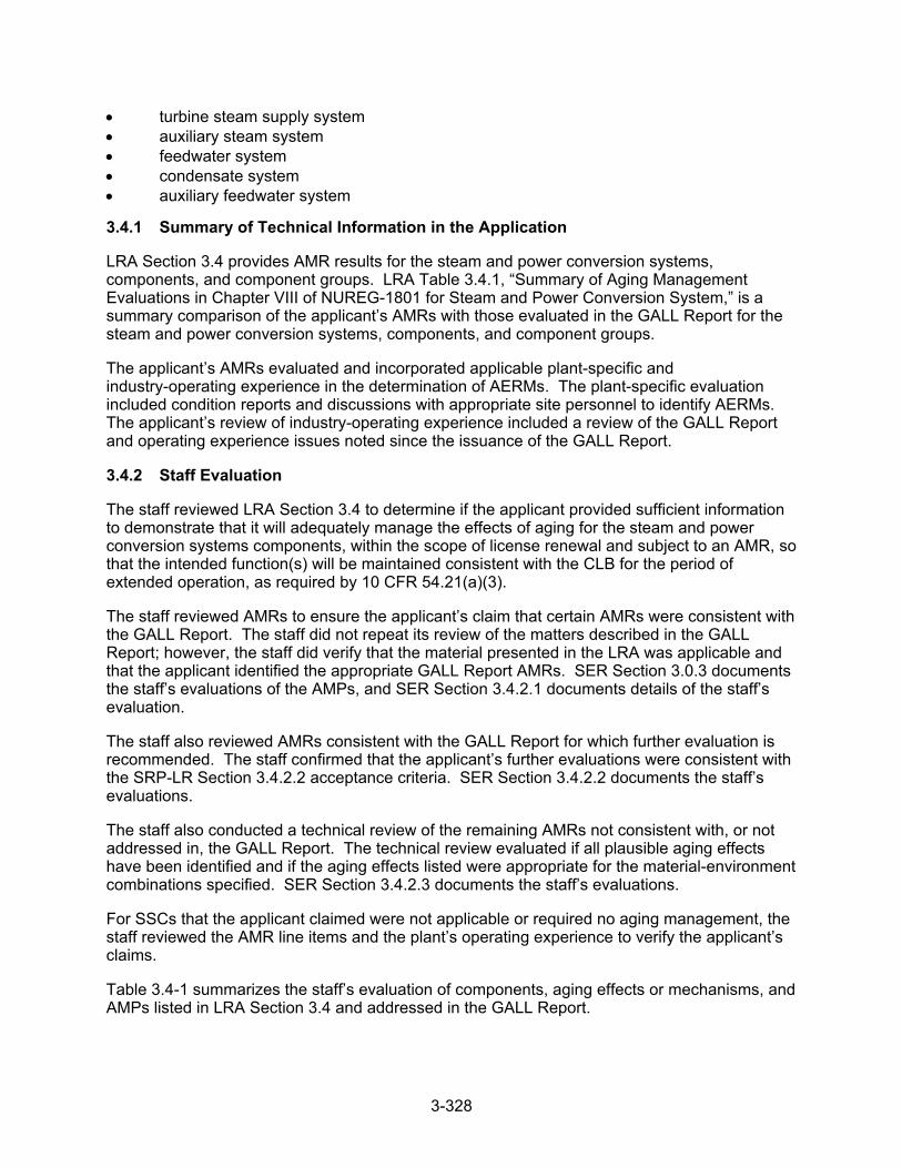
3-328
turbine steam supply system auxiliary steam system feedwater system condensate system auxiliary feedwater system
3.4.1 Summary of Technical Information in the Application
LRA Section 3.4 provides AMR results for the steam and power conversion systems, components, and component groups. LRA Table 3.4.1, “Summary of Aging Management Evaluations in Chapter VIII of NUREG-1801 for Steam and Power Conversion System,” is a summary comparison of the applicant’s AMRs with those evaluated in the GALL Report for the steam and power conversion systems, components, and component groups.
The applicant’s AMRs evaluated and incorporated applicable plant-specific and industry-operating experience in the determination of AERMs. The plant-specific evaluation included condition reports and discussions with appropriate site personnel to identify AERMs. The applicant’s review of industry-operating experience included a review of the GALL Report and operating experience issues noted since the issuance of the GALL Report.
3.4.2 Staff Evaluation
The staff reviewed LRA Section 3.4 to determine if the applicant provided sufficient information to demonstrate that it will adequately manage the effects of aging for the steam and power conversion systems components, within the scope of license renewal and subject to an AMR, so that the intended function(s) will be maintained consistent with the CLB for the period of extended operation, as required by 10 CFR 54.21(a)(3).
The staff reviewed AMRs to ensure the applicant’s claim that certain AMRs were consistent with the GALL Report. The staff did not repeat its review of the matters described in the GALL Report; however, the staff did verify that the material presented in the LRA was applicable and that the applicant identified the appropriate GALL Report AMRs. SER Section 3.0.3 documents the staff’s evaluations of the AMPs, and SER Section 3.4.2.1 documents details of the staff’s evaluation.
The staff also reviewed AMRs consistent with the GALL Report for which further evaluation is recommended. The staff confirmed that the applicant’s further evaluations were consistent with the SRP-LR Section 3.4.2.2 acceptance criteria. SER Section 3.4.2.2 documents the staff’s evaluations.
The staff also conducted a technical review of the remaining AMRs not consistent with, or not addressed in, the GALL Report. The technical review evaluated if all plausible aging effects have been identified and if the aging effects listed were appropriate for the material-environment combinations specified. SER Section 3.4.2.3 documents the staff’s evaluations.
For SSCs that the applicant claimed were not applicable or required no aging management, the staff reviewed the AMR line items and the plant’s operating experience to verify the applicant’s claims.
Table 3.4-1 summarizes the staff’s evaluation of components, aging effects or mechanisms, and AMPs listed in LRA Section 3.4 and addressed in the GALL Report.
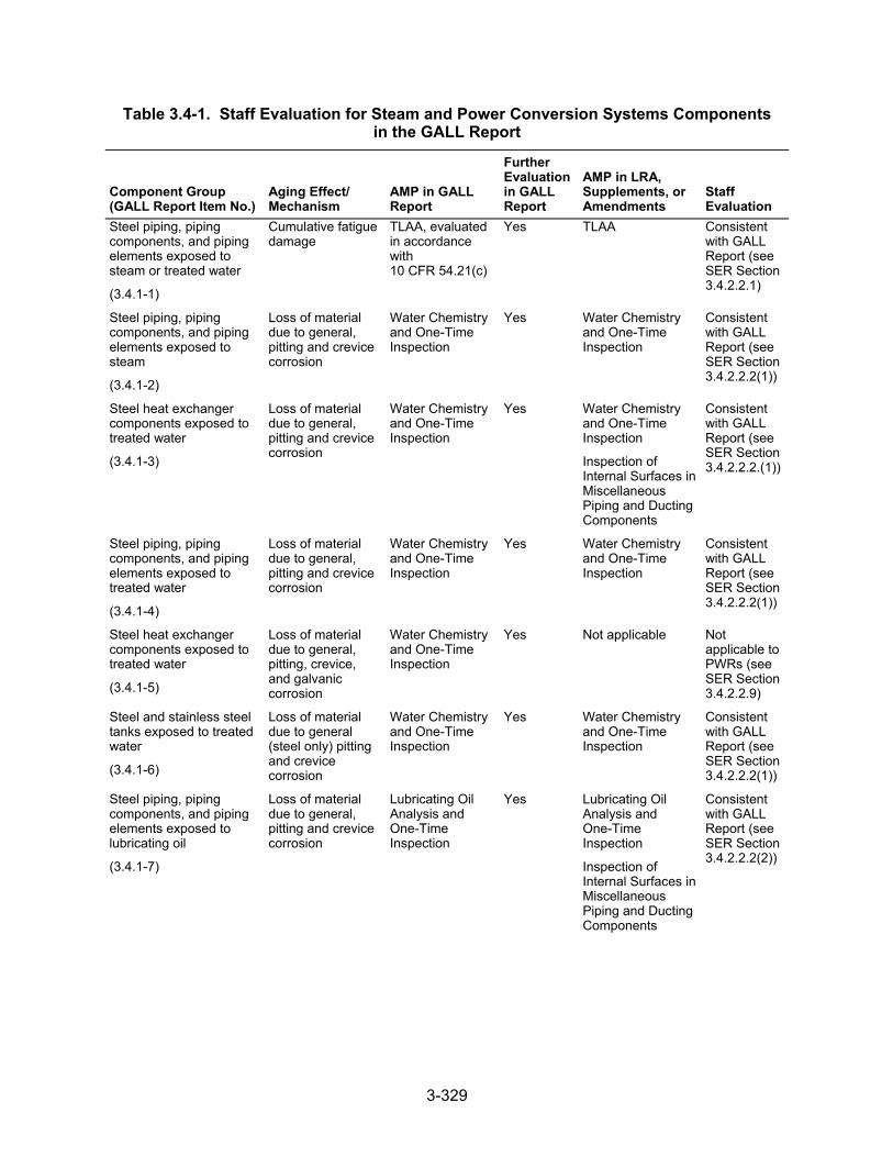
3-329
Table 3.4-1. Staff Evaluation for Steam and Power Conversion Systems Components in the GALL Report
Component Group (GALL Report Item No.)
Aging Effect/ Mechanism
AMP in GALL Report
Further Evaluation in GALL Report
AMP in LRA, Supplements, or Amendments
Staff Evaluation
Steel piping, piping components, and piping elements exposed to steam or treated water
(3.4.1-1)
Cumulative fatigue damage
TLAA, evaluated in accordance with 10 CFR 54.21(c)
Yes TLAA Consistent with GALL Report (see SER Section 3.4.2.2.1)
Steel piping, piping components, and piping elements exposed to steam
(3.4.1-2)
Loss of material due to general, pitting and crevice corrosion
Water Chemistry and One-Time Inspection
Yes Water Chemistry and One-Time Inspection
Consistent with GALL Report (see SER Section 3.4.2.2.2(1))
Steel heat exchanger components exposed to treated water
(3.4.1-3)
Loss of material due to general, pitting and crevice corrosion
Water Chemistry and One-Time Inspection
Yes Water Chemistry and One-Time Inspection
Inspection of Internal Surfaces in Miscellaneous Piping and Ducting Components
Consistent with GALL Report (see SER Section 3.4.2.2.2.(1))
Steel piping, piping components, and piping elements exposed to treated water
(3.4.1-4)
Loss of material due to general, pitting and crevice corrosion
Water Chemistry and One-Time Inspection
Yes Water Chemistry and One-Time Inspection
Consistent with GALL Report (see SER Section 3.4.2.2.2(1))
Steel heat exchanger components exposed to treated water
(3.4.1-5)
Loss of material due to general, pitting, crevice, and galvanic corrosion
Water Chemistry and One-Time Inspection
Yes Not applicable Not applicable to PWRs (see SER Section 3.4.2.2.9)
Steel and stainless steel tanks exposed to treated water
(3.4.1-6)
Loss of material due to general (steel only) pitting and crevice corrosion
Water Chemistry and One-Time Inspection
Yes Water Chemistry and One-Time Inspection
Consistent with GALL Report (see SER Section 3.4.2.2.2(1))
Steel piping, piping components, and piping elements exposed to lubricating oil
(3.4.1-7)
Loss of material due to general, pitting and crevice corrosion
Lubricating Oil Analysis and One-Time Inspection
Yes Lubricating Oil Analysis and One-Time Inspection
Inspection of Internal Surfaces in Miscellaneous Piping and Ducting Components
Consistent with GALL Report (see SER Section 3.4.2.2.2(2))
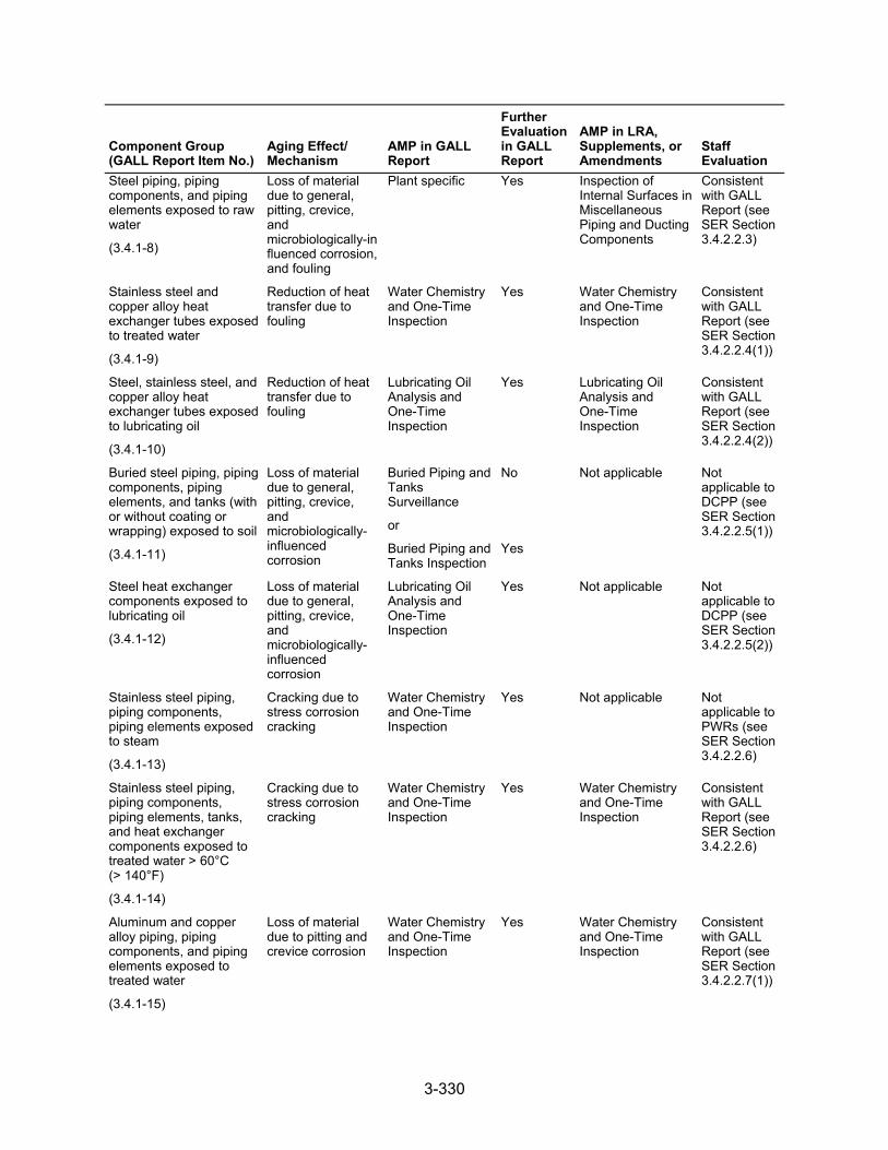
3-330
Component Group (GALL Report Item No.)
Aging Effect/ Mechanism
AMP in GALL Report
Further Evaluation in GALL Report
AMP in LRA, Supplements, or Amendments
Staff Evaluation
Steel piping, piping components, and piping elements exposed to raw water
(3.4.1-8)
Loss of material due to general, pitting, crevice, and microbiologically-influenced corrosion, and fouling
Plant specific Yes Inspection of Internal Surfaces in Miscellaneous Piping and Ducting Components
Consistent with GALL Report (see SER Section 3.4.2.2.3)
Stainless steel and copper alloy heat exchanger tubes exposed to treated water
(3.4.1-9)
Reduction of heat transfer due to fouling
Water Chemistry and One-Time Inspection
Yes Water Chemistry and One-Time Inspection
Consistent with GALL Report (see SER Section 3.4.2.2.4(1))
Steel, stainless steel, and copper alloy heat exchanger tubes exposed to lubricating oil
(3.4.1-10)
Reduction of heat transfer due to fouling
Lubricating Oil Analysis and One-Time Inspection
Yes Lubricating Oil Analysis and One-Time Inspection
Consistent with GALL Report (see SER Section 3.4.2.2.4(2))
Buried steel piping, piping components, piping elements, and tanks (with or without coating or wrapping) exposed to soil
(3.4.1-11)
Loss of material due to general, pitting, crevice, and microbiologically- influenced corrosion
Buried Piping and Tanks Surveillance
or
Buried Piping and Tanks Inspection
No
Yes
Not applicable Not applicable to DCPP (see SER Section 3.4.2.2.5(1))
Steel heat exchanger components exposed to lubricating oil
(3.4.1-12)
Loss of material due to general, pitting, crevice, and microbiologically- influenced corrosion
Lubricating Oil Analysis and One-Time Inspection
Yes Not applicable Not applicable to DCPP (see SER Section 3.4.2.2.5(2))
Stainless steel piping, piping components, piping elements exposed to steam
(3.4.1-13)
Cracking due to stress corrosion cracking
Water Chemistry and One-Time Inspection
Yes Not applicable Not applicable to PWRs (see SER Section 3.4.2.2.6)
Stainless steel piping, piping components, piping elements, tanks, and heat exchanger components exposed to treated water > 60°C (> 140°F)
(3.4.1-14)
Cracking due to stress corrosion cracking
Water Chemistry and One-Time Inspection
Yes Water Chemistry and One-Time Inspection
Consistent with GALL Report (see SER Section 3.4.2.2.6)
Aluminum and copper alloy piping, piping components, and piping elements exposed to treated water
(3.4.1-15)
Loss of material due to pitting and crevice corrosion
Water Chemistry and One-Time Inspection
Yes Water Chemistry and One-Time Inspection
Consistent with GALL Report (see SER Section 3.4.2.2.7(1))
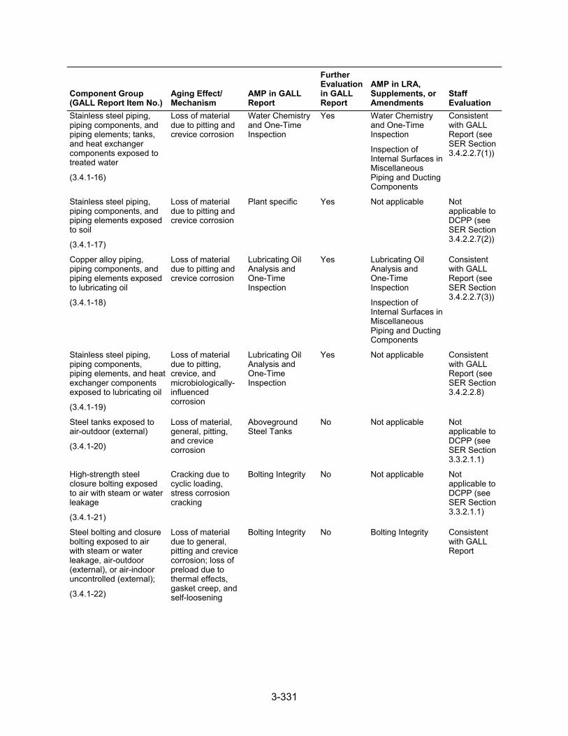
3-331
Component Group (GALL Report Item No.)
Aging Effect/ Mechanism
AMP in GALL Report
Further Evaluation in GALL Report
AMP in LRA, Supplements, or Amendments
Staff Evaluation
Stainless steel piping, piping components, and piping elements; tanks, and heat exchanger components exposed to treated water
(3.4.1-16)
Loss of material due to pitting and crevice corrosion
Water Chemistry and One-Time Inspection
Yes Water Chemistry and One-Time Inspection
Inspection of Internal Surfaces in Miscellaneous Piping and Ducting Components
Consistent with GALL Report (see SER Section 3.4.2.2.7(1))
Stainless steel piping, piping components, and piping elements exposed to soil
(3.4.1-17)
Loss of material due to pitting and crevice corrosion
Plant specific Yes Not applicable Not applicable to DCPP (see SER Section 3.4.2.2.7(2))
Copper alloy piping, piping components, and piping elements exposed to lubricating oil
(3.4.1-18)
Loss of material due to pitting and crevice corrosion
Lubricating Oil Analysis and One-Time Inspection
Yes Lubricating Oil Analysis and One-Time Inspection
Inspection of Internal Surfaces in Miscellaneous Piping and Ducting Components
Consistent with GALL Report (see SER Section 3.4.2.2.7(3))
Stainless steel piping, piping components, piping elements, and heat exchanger components exposed to lubricating oil
(3.4.1-19)
Loss of material due to pitting, crevice, and microbiologically- influenced corrosion
Lubricating Oil Analysis and One-Time Inspection
Yes Not applicable Consistent with GALL Report (see SER Section 3.4.2.2.8)
Steel tanks exposed to air-outdoor (external)
(3.4.1-20)
Loss of material, general, pitting, and crevice corrosion
Aboveground Steel Tanks
No Not applicable Not applicable to DCPP (see SER Section 3.3.2.1.1)
High-strength steel closure bolting exposed to air with steam or water leakage
(3.4.1-21)
Cracking due to cyclic loading, stress corrosion cracking
Bolting Integrity No Not applicable Not applicable to DCPP (see SER Section 3.3.2.1.1)
Steel bolting and closure bolting exposed to air with steam or water leakage, air-outdoor (external), or air-indoor uncontrolled (external);
(3.4.1-22)
Loss of material due to general, pitting and crevice corrosion; loss of preload due to thermal effects, gasket creep, and self-loosening
Bolting Integrity No Bolting Integrity Consistent with GALL Report
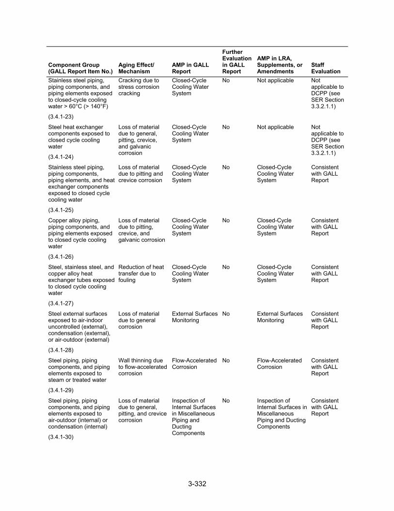
3-332
Component Group (GALL Report Item No.)
Aging Effect/ Mechanism
AMP in GALL Report
Further Evaluation in GALL Report
AMP in LRA, Supplements, or Amendments
Staff Evaluation
Stainless steel piping, piping components, and piping elements exposed to closed-cycle cooling water > 60°C (> 140°F)
(3.4.1-23)
Cracking due to stress corrosion cracking
Closed-Cycle Cooling Water System
No Not applicable Not applicable to DCPP (see SER Section 3.3.2.1.1)
Steel heat exchanger components exposed to closed cycle cooling water
(3.4.1-24)
Loss of material due to general, pitting, crevice, and galvanic corrosion
Closed-Cycle Cooling Water System
No Not applicable Not applicable to DCPP (see SER Section 3.3.2.1.1)
Stainless steel piping, piping components, piping elements, and heat exchanger components exposed to closed cycle cooling water
(3.4.1-25)
Loss of material due to pitting and crevice corrosion
Closed-Cycle Cooling Water System
No Closed-Cycle Cooling Water System
Consistent with GALL Report
Copper alloy piping, piping components, and piping elements exposed to closed cycle cooling water
(3.4.1-26)
Loss of material due to pitting, crevice, and galvanic corrosion
Closed-Cycle Cooling Water System
No Closed-Cycle Cooling Water System
Consistent with GALL Report
Steel, stainless steel, and copper alloy heat exchanger tubes exposed to closed cycle cooling water
(3.4.1-27)
Reduction of heat transfer due to fouling
Closed-Cycle Cooling Water System
No Closed-Cycle Cooling Water System
Consistent with GALL Report
Steel external surfaces exposed to air-indoor uncontrolled (external), condensation (external), or air-outdoor (external)
(3.4.1-28)
Loss of material due to general corrosion
External Surfaces Monitoring
No External Surfaces Monitoring
Consistent with GALL Report
Steel piping, piping components, and piping elements exposed to steam or treated water
(3.4.1-29)
Wall thinning due to flow-accelerated corrosion
Flow-Accelerated Corrosion
No Flow-Accelerated Corrosion
Consistent with GALL Report
Steel piping, piping components, and piping elements exposed to air-outdoor (internal) or condensation (internal)
(3.4.1-30)
Loss of material due to general, pitting, and crevice corrosion
Inspection of Internal Surfaces in Miscellaneous Piping and Ducting Components
No Inspection of Internal Surfaces in Miscellaneous Piping and Ducting Components
Consistent with GALL Report
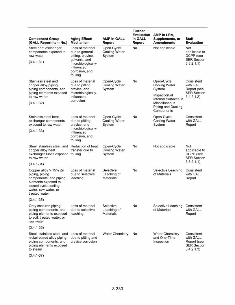
3-333
Component Group (GALL Report Item No.)
Aging Effect/ Mechanism
AMP in GALL Report
Further Evaluation in GALL Report
AMP in LRA, Supplements, or Amendments
Staff Evaluation
Steel heat exchanger components exposed to raw water
(3.4.1-31)
Loss of material due to general, pitting, crevice, galvanic, and microbiologically- influenced corrosion, and fouling
Open-Cycle Cooling Water System
No Not applicable Not applicable to DCPP (see SER Section 3.3.2.1.1)
Stainless steel and copper alloy piping, piping components, and piping elements exposed to raw water
(3.4.1-32)
Loss of material due to pitting, crevice, and microbiologically- influenced corrosion
Open-Cycle Cooling Water System
No Open-Cycle Cooling Water System
Inspection of Internal Surfaces in Miscellaneous Piping and Ducting Components
Consistent with GALL Report (see SER Section 3.4.2.1.2)
Stainless steel heat exchanger components exposed to raw water
(3.4.1-33)
Loss of material due to pitting, crevice, and microbiologically- influenced corrosion, and fouling
Open-Cycle Cooling Water System
No Open-Cycle Cooling Water System
Consistent with GALL Report
Steel, stainless steel, and copper alloy heat exchanger tubes exposed to raw water
(3.4.1-34)
Reduction of heat transfer due to fouling
Open-Cycle Cooling Water System
No Not applicable Not applicable to DCPP (see SER Section 3.3.2.1.1)
Copper alloy > 15% Zn piping, piping components, and piping elements exposed to closed cycle cooling water, raw water, or treated water
(3.4.1-35)
Loss of material due to selective leaching
Selective Leaching of Materials
No Selective Leaching of Materials
Consistent with GALL Report
Gray cast iron piping, piping components, and piping elements exposed to soil, treated water, or raw water
(3.4.1-36)
Loss of material due to selective leaching
Selective Leaching of Materials
No Selective Leaching of Materials
Consistent with GALL Report
Steel, stainless steel, and nickel-based alloy piping, piping components, and piping elements exposed to steam
(3.4.1-37)
Loss of material due to pitting and crevice corrosion
Water Chemistry No Water Chemistry and One-Time Inspection
Consistent with GALL Report (see SER Section 3.4.2.1.3)
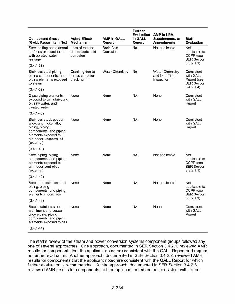
3-334
Component Group (GALL Report Item No.)
Aging Effect/ Mechanism
AMP in GALL Report
Further Evaluation in GALL Report
AMP in LRA, Supplements, or Amendments
Staff Evaluation
Steel bolting and external surfaces exposed to air with borated water leakage
(3.4.1-38)
Loss of material due to boric acid corrosion
Boric Acid Corrosion
No Not applicable Not applicable to DCPP (see SER Section 3.3.2.1.1)
Stainless steel piping, piping components, and piping elements exposed to steam
(3.4.1-39)
Cracking due to stress corrosion cracking
Water Chemistry No Water Chemistry and One-Time Inspection
Consistent with GALL Report (see SER Section 3.4.2.1.4)
Glass piping elements exposed to air, lubricating oil, raw water, and treated water
(3.4.1-40)
None None NA None Consistent with GALL Report
Stainless steel, copper alloy, and nickel alloy piping, piping components, and piping elements exposed to air-indoor uncontrolled (external)
(3.4.1-41)
None None NA None Consistent with GALL Report
Steel piping, piping components, and piping elements exposed to air-indoor controlled (external)
(3.4.1-42)
None None NA Not applicable Not applicable to DCPP (see SER Section 3.3.2.1.1)
Steel and stainless steel piping, piping components, and piping elements in concrete
(3.4.1-43)
None None NA Not applicable Not applicable to DCPP (see SER Section 3.3.2.1.1)
Steel, stainless steel, aluminum, and copper alloy piping, piping components, and piping elements exposed to gas
(3.4.1-44)
None None NA None Consistent with GALL Report
The staff’s review of the steam and power conversion systems component groups followed any one of several approaches. One approach, documented in SER Section 3.4.2.1, reviewed AMR results for components that the applicant noted are consistent with the GALL Report and require no further evaluation. Another approach, documented in SER Section 3.4.2.2, reviewed AMR results for components that the applicant noted are consistent with the GALL Report for which further evaluation is recommended. A third approach, documented in SER Section 3.4.2.3, reviewed AMR results for components that the applicant noted are not consistent with, or not
3-335
addressed in, the GALL Report. SER Section 3.0.3 documents the staff’s review of AMPs credited to manage or monitor aging effects of the steam and power conversion systems components.
3.4.2.1 AMR Results Consistent with the GALL Report
LRA Section 3.4.2.1 identifies the materials, environments, AERMs, and the following programs that manage aging effects for the steam and power conversion systems components:
Bolting Integrity Closed-Cycle Cooling Water System External Surfaces Monitoring Flow-Accelerated Corrosion Inspection of Internal Surfaces in Miscellaneous Piping and Ducting Components Lubricating Oil Analysis One-Time Inspection Open-Cycle Cooling Water System Selective Leaching of Materials Water Chemistry
LRA Tables 3.4.2-1 through 3.4.2-20 summarize AMRs for the steam and power conversion systems components and note AMRs claimed to be consistent with the GALL Report.
As discussed in SER Section 3.0.2.2.2, the applicant provided AMR results which cited generic notes A through J to indicate the AMR’s consistency with the GALL Report. The staff reviewed the information in the LRA for AMRs that the applicant claimed were consistent with the GALL Report (i.e., those AMR items the applicant cited generic notes A through E). The staff did not repeat its review of the matters described in the GALL Report; however, the staff did verify that the material presented in the LRA was applicable and that the applicant identified the appropriate GALL Report AMRs.
The staff reviewed the LRA to confirm that the applicant: (a) provided a brief description of the system, components, materials, and environments; (b) stated that the applicable aging effects were reviewed and evaluated in the GALL Report; and (c) identified those aging effects for the steam and power conversion systems components that are subject to an AMR. For those AMRs that the applicant claimed consistency, the staff compared the LRA AMRs to the corresponding GALL Report AMRs to verify the applicant’s claim of consistency. The staff’s evaluation follows.
3.4.2.1.1 AMR Results Identified as Not Applicable
LRA Table 3.4.1, items 3.4.1.05 and 3.4.1.13, state that these line items are applicable only to BWRs. The staff verified that these line items do not apply because the units are a PWR design. Based on this determination, the staff finds that the applicant has supplied an acceptable basis for concluding AMR items 3.4.1.5 and 3.4.1.13 are not applicable.
LRA Table 3.4.1, items 3.4.1.20, 3.4.1.21, 3.4.1.23, 3.4.1.38, and 3.4.1.43 state that these items are not applicable to DCPP. The staff reviewed the LRA and FSAR and confirmed that the applicant’s LRA does not have any AMR results that are applicable for these line items.
LRA Table 3.4.1, item 3.4.1.24, addresses steel heat exchanger components exposed to closed-cycle cooling water. The GALL Report recommends use of GALL AMP XI.M21, “Closed-Cycle Cooling Water System,” to manage loss of material due to general, pitting,
3-336
crevice, and galvanic corrosion for this component group. The applicant stated that this line item is not applicable because it has no in-scope steel heat exchanger components exposed to closed-cycle cooling water in the steam and power conversion systems. The staff reviewed LRA Sections 2.3.4 and 3.4 and found a line item annotating a carbon steel heat exchanger in the closed-cycle cooling water environment in LRA Table 3.4.2-2, “Auxiliary Steam System.” The staff noted that the applicant applied LRA Table 3.3.1, item 3.3.1.48, to this item, which is comparable to LRA Table 3.4.1, item 3.4.1.24, in that it applies to the same component type, the same aging effects and mechanisms, the same AMP; it also does not recommend further evaluation. Based on the comparable nature of these items, the staff finds the applicant’s determination acceptable.
LRA Table 3.4.1, item 3.4.1.31, addresses loss of material due to general, pitting, crevice, galvanic, and MIC in steel heat exchanger components exposed to raw water. The applicant stated that this line item is not applicable because there are no in-scope steel heat exchanger components exposed to raw water in the steam and power conversion systems. However, the staff reviewed LRA Sections 2.3.4 and 3.4 and found a carbon steel heat exchanger exposed to raw water in LRA Table 3.4.2-2, “Auxiliary Steam System.” This item is annotated with a plant-specific note, which states that the in-scope components are abandoned-in-place, and the Open-Cycle Cooling Water System Program does not apply. Because this item is abandoned-in-place, the staff finds it acceptable that this item is not evaluated by the Open-Cycle Cooling Water System Program. In addition, staff confirmed that the applicant’s LRA does not have any further AMR results for the steam and power conversion system that include steel heat exchanger components exposed to raw water. The staff reviewed the applicant’s FSAR and confirmed that no other in-scope heat exchanger components exposed to raw water are present in the steam and power conversion systems and, therefore, finds the applicant’s determination acceptable.
LRA Table 3.4.1, item 3.4.1.34, addresses steel, stainless steel, and copper-alloy heat exchanger tubes exposed to raw water. The GALL Report recommends use of GALL AMP XI.M20, “Open-Cycle Cooling Water System,” to manage reduction of heat transfer due to fouling for this component group. The applicant stated that this line item is not applicable because there are no in-scope steel, stainless steel or copper-alloy heat exchanger tubes exposed to raw water in the steam and power conversion systems. The staff reviewed LRA Sections 2.3.4 and 3.4 and found a carbon steel heat exchanger exposed to raw water in LRA Table 3.4.2-2, “Auxiliary Steam System.” This item is annotated with a plant-specific note, which states that the in-scope components are abandoned-in-place. Because this item is abandoned-in-place, the staff finds it acceptable that this item is not evaluated by the Open-Cycle Cooling Water System Program for management of reduction of heat transfer by fouling. The staff reviewed the applicant’s FSAR and confirmed that no other in-scope steel, stainless steel or copper-alloy heat exchanger tubes exposed to raw water are present in the steam and power conversion systems and, therefore, finds the applicant’s determination acceptable.
LRA Table 3.4.1, item 3.4.1.42, addresses steel piping, piping components, and piping elements exposed to air-indoor controlled (external). The GALL Report recommends that there is no AERM, and there is no recommended AMP. The applicant stated that this line item is not applicable because there are no in-scope steel components in the steam and power conversion systems exposed to air-indoor controlled. The staff finds the applicant’s proposal acceptable because, based on a review of LRA Tables 3.4.2-1 through 3.4.2-5, each table has an AMR line item for carbon steel pipe exposed to “plant indoor air (external)”, which uses the External Surfaces Monitoring Program to manage the loss of material aging effect, and the GALL Report recommends that there is no AERM or recommended AMP for these components exposed to “air-indoor controlled (external).”
3-337
3.4.2.1.2 Loss of Material Due to Pitting, Crevice, and Microbiologically-Influenced Corrosion
LRA Table 3.4.1, item 3.4.1.32, addresses stainless steel and copper-alloy piping, piping components, and piping elements exposed to raw water, which are managed for loss of material due to pitting, crevice, and MIC. The LRA credits the Inspection of Internal Surfaces in Miscellaneous Piping and Ducting Components Program to manage these aging effects for stainless steel piping, pumps, valves, strainers, and test connections as well as copper-alloy (including greater than 8 percent aluminum) valves and sight gauges in LRA Tables 3.2.2-4, 3.4.2-2, and 3.4.2-4. The GALL Report recommends GALL AMP XI.M20, “Open-Cycle Cooling Water System,” to ensure that these aging effects are adequately managed. The associated AMR line items cite generic note E. The associated AMR line items in Table 3.2.2-4 also cite plant-specific note 3, which states that the “[c]omponent internal environment is condensation from cooling coil drains that is evaluated as raw water per the GALL Report, Section IX. This raw water environment is managed by the applicant’s Inspection of Internal Surfaces in Miscellaneous Piping and Ducting Components AMP (B2.1.22) because it is not suitable for management by the applicant’s Open-Cycle Cooling Water program (B2.1.9).” The associated AMR line items in Table 3.4.2-2 also cite plant-specific note 5, which states that “the in-scope auxiliary steam system components which may have a raw water environment are abandoned-in-place. Thus, the Open-Cycle Cooling Water System aging management program does not apply.” The associated AMR line items in Table 3.4.2-4 also cite plant-specific note 2, which states that “[t]he in-scope condensate system components which may have a raw water environment are abandoned-in place. Thus, the Open-Cycle Cooling Water System aging management program does not apply.”
For the line item associated with generic note E, GALL AMP XI.M20 recommends using water chemistry controls, as described in GL 89-13. GALL AMP XI.M20 also recommends preventive measures including proper selection of materials and coatings, periodic flushes and cleaning, and raw water chemistry control. GALL AMP XI.M20 further recommends visual inspections and NDE testing of components exposed to open-cycle cooling water. The staff noted that open-cycle cooling water is water that transfers heat from safety-related components to the ultimate heat sink. The staff also noted that raw water is untreated water, not monitored by a chemistry program that may contain contaminants, including oil and boric acid, depending on the location. In its review of components associated with LRA Table 3.4.1, item 3.4.1.32, for which the applicant cited generic note E, the staff noted that the Inspection of Internal Surfaces in Miscellaneous Piping and Ducting Components Program proposes to manage the aging effects of stainless steel piping, piping elements and components, and other components for loss of material due to pitting, crevice, and MIC.
SER Section 3.0.3.2.11 documents the staff’s evaluation of the applicant’s proposed Internal Surfaces in Miscellaneous Piping and Ducting Components. The staff noted that the Inspection of Internal Surfaces in Miscellaneous Piping and Ducting Components Program includes opportunistic and supplemental visual inspections of the internal surfaces of components. While the opportunistic inspections are process-driven (work control process), the supplemental inspections are based on potential degradation of components (which could lead to loss of intended function) and on current industry and plant-specific operating experience. The staff also noted that these components are exposed to environments such as condensation from cooling coil drains, which do not fit the definition of open-cycle cooing water or are isolated abandoned components. The staff further noted that the components listed in LRA Tables 3.2.2-4, 3.4.2-2, and 3.4.2-4 and evaluated under LRA Table 3.4.1, item 3.4.1-32, with note E, are evaluated under similar visual inspections as recommended by the Open-Cycle Cooling Water System Program when exposed to raw water. The staff finds the applicant’s Inspection of Internal Surfaces in Miscellaneous Piping and Ducting Components Program acceptable to manage aging for these components because it includes visual inspections that are adequate to
3-338
monitor for component degradation and will, therefore, be effective in managing their aging effects.
The staff concludes that the applicant has demonstrated that it will adequately manage the effects of aging for these components so that their intended function(s) will be maintained consistent with the CLB during the period of extended operation, as required by 10 CFR 54.21(a)(3).
3.4.2.1.3 Loss of Material Due to Pitting and Crevice Corrosion
LRA Table 3.4.1, item 3.4.1.37, addresses steel, stainless steel, and nickel-based alloy piping, piping components, and piping elements exposed to steam, which are managed for loss of material due to pitting and crevice corrosion. The LRA credits the Water Chemistry and One-Time Inspection Programs to manage the aging effect. The GALL Report recommends GALL AMP XI.M2, “Water Chemistry Program,” to ensure that these aging effects are adequately managed. The associated AMR line items cite generic note E.
For those line items associated with generic note E, GALL AMP XI.M2 recommends using mitigation measures, such as maintaining low levels of corrosive impurities by maintaining the chemical environment through water chemistry controls based on industry guidelines. In its review of components associated with LRA Table 3.4.1, item 3.4.1.37, for which the applicant cited generic note E, the staff noted that the Water Chemistry and the One-Time Inspection Programs propose to manage the aging of steel, stainless steel, and nickel-based alloy piping, piping components, and piping elements exposed to steam through the use of mitigation measures based on industry guidelines, such as maintaining low levels of known detrimental contaminants and one-time inspection to verify the effectiveness of the Water Chemistry Program in low-flow and stagnant-flow areas.
SER Sections 3.0.3.1.2 and 3.0.3.1.10 document the staff’s evaluation of the applicant’s Water Chemistry and One-Time Inspection Programs, respectively. In its review of components associated with LRA Table 3.4.1, item 3.4.1.37, the staff finds the applicant’s proposal to manage aging using the specified programs acceptable because the Water Chemistry Program will monitor and control the chemical environment to ensure that the aging effects due to contaminants are limited, and the One-Time Inspection Program will verify the effectiveness of the Water Chemistry Program for managing the effects of aging due to the potential corrosion mechanisms.
The staff concludes that the applicant has demonstrated that it will adequately manage the effects of aging for these components so that their intended function(s) will be maintained consistent with the CLB during the period of extended operation, as required by 10 CFR 54.21(a)(3).
3.4.2.1.4 Cracking Due to Stress Corrosion Cracking
LRA Table 3.4.1, item 3.4.1.39, addresses stainless steel components exposed to steam, which are managed for cracking due to SCC. The LRA credits the Water Chemistry Program and One-Time Inspection Programs to manage the aging effect. The GALL Report recommends GALL AMP XI.M2, “Water Chemistry,” to ensure that these aging effects are adequately managed. The AMR line items cite generic note E.
For those line items associated with generic note E, GALL AMP XI.M2 recommends using sampling, analyzing, and controlling water chemistry in accordance with the EPRI water chemistry guidelines to manage the aging of these line items. In its review of components
3-339
associated with LRA Table 3.4.1, item 3.4.1.39, for which the applicant cited generic note E, the staff noted that the applicant’s Water Chemistry and One-Time Inspection Programs propose to manage the aging of stainless steel components through the use of sampling, analyzing, and controlling water chemistry, in accordance with the EPRI water chemistry guidelines, augmented by a one-time inspection of selected components at susceptible locations.
SER Sections 3.0.3.1.2 and 3.0.3.1.10 document the staff’s evaluation of the applicant’s Water Chemistry and One-Time Inspection Programs, respectively. In its review of components associated with LRA Table 3.4.1, item 3.4.1.39, the staff finds the applicant’s proposal to manage aging using the Water Chemistry Program and One-Time Inspection Program acceptable for the following reasons:
The Water Chemistry Program establishes the plant water chemistry control parameters and, if the parameters exceed limits, identifies and performs the required actions to control the water chemistry such that SCC of the components is mitigated, consistent with the recommendation of the GALL Report.
The applicant conservatively credits its One-Time Inspection Program, which includes an adequate one-time, NDE of selected components to confirm that the effectiveness of the Water Chemistry Program is adequate to manage cracking due to SCC.
The staff concludes that the applicant has demonstrated that it will adequately manage the effects of aging for these components so that the intended function(s) will be maintained consistent with the CLB during the period of extended operation, as required by 10 CFR 54.21(a)(3).
3.4.2.1.5 Conclusion
The staff evaluated the GALL Report AMR items that the applicant claimed were not applicable. On the basis of its review, the staff concludes that the AMR results which the applicant claimed were not applicable.
As discussed in SER Section 3.4.2.1, for those AMRs that the applicant claimed consistency with the GALL Report, the staff evaluated the applicant’s claim of consistency. The staff also reviewed information pertaining to the applicant’s consideration of recent operating experience and proposals for managing aging effects. On the basis of its review, the staff concludes that the AMR results, which the applicant claimed to be consistent with the GALL Report, are consistent.
Therefore, the staff concludes that the applicant has demonstrated that the effects of aging for these components will be adequately managed so that their intended function(s) will be maintained consistent with the CLB during the period of extended operation, as required by 10 CFR 54.21(a)(3).
3.4.2.2 AMR Results Consistent with the GALL Report for Which Further Evaluation Is Recommended
In LRA Section 3.4.2.2, the applicant further evaluates aging management, as recommended by the GALL Report, for the steam and power conversion systems components and provides information concerning how it will manage the following aging effects:
cumulative fatigue damage loss of material due to general, pitting, and crevice corrosion loss of material due to general, pitting, crevice, and MIC, and fouling
3-340
reduction of heat transfer due to fouling loss of material due to general, pitting, crevice, and MIC cracking due to SCC loss of material due to pitting and crevice corrosion loss of material due to pitting, crevice, and MIC loss of material due to general, pitting, crevice, and galvanic corrosion QA for aging management of nonsafety-related components
For component groups evaluated in the GALL Report, for which the applicant claimed consistency with the report and for which the report recommends further evaluation, the staff reviewed the applicant’s evaluation to determine if it adequately addressed the issues further evaluated. In addition, the staff reviewed the applicant’s further evaluations against the criteria contained in SRP-LR Section 3.4.2.2.The staff’s review of the applicant’s further evaluation follows.
3.4.2.2.1 Cumulative Fatigue Damage
LRA Section 3.4.2.2.1 states that the evaluation of fatigue is a TLAA, as defined in 10 CFR 54.3. TLAAs are evaluated in accordance with 10 CFR 54.21(c)(1). The applicant stated the piping outside the RCPB is designed to ANSI B31.1 and B31.7, which assumes a reduction in the allowable secondary stress range if more than 7,000 full-range thermal cycles are expected in a design lifetime. In LRA Table 3.4.1, item 3.4.1.01, the applicant stated that it will manage cumulative fatigue damage for its steam and power conversion system piping, piping components, and piping elements using a TLAA. Furthermore, LRA Section 4.3.5 describes the evaluation of these cyclic design TLAAs.
The staff reviewed LRA Section 3.4.2.2.1 against the criteria in SRP-LR Section 3.4.2.2.1, which states that fatigue is a TLAA, as defined in 10 CFR 54.3. TLAAs are required to be evaluated in accordance with 10 CFR 54.21(c)(1). The staff also reviewed the AMRs discussed in this section against the GALL Report items for evaluating cumulative fatigue damage in PWR steam and power conversion system designs.
With regard to the applicant’s metal fatigue AMR assessment, the staff noted that the GALL Report, items VIII.B1-10, VIII.D1-7, and VIII.G-37, note that cumulative fatigue damage is an applicable aging effect for steel piping, piping components, and piping elements. The staff also noted that the GALL Report recommends that the TLAA on metal fatigue be used to manage the affect of cumulative fatigue damage in these components. The staff noted that, in conformance with this recommendation, the applicant included an applicable line item in LRA Tables 3.4.2-1, 3.4.2-4, and 3.4.2-5 for steel piping that received ASME Section III CUF or ANSI B31.1 design code analysis calculations. The staff noted that the applicant credited the TLAA in LRA Section 4.3.5 with the management of cumulative fatigue damage in these components. The staff noted that the applicant did not include any GALL Report items for any of the other steam and power conversion system tables. The GALL Report items are to be used as a guide for noting the items that are relevant to an LRA. The staff noted that once the applicant has identified a given subsystem as within the scope of license renewal and subject to an AMR, the lack of an equivalent GALL Report item is not a basis for not including components in the LRA with an associated AMR line item. LRA Section 4.3.5 notes that the ANSI B31.1 and B31.7 piping components were required to receive implicit fatigue analyses under the ANSI B31.1 and B31.7 design codes. The staff noted that the LRA should also include applicable GALL Report items on cumulative fatigue damage if the systems include ANSI B31.1 or B31.7 piping that is within the scope of license renewal and subject to an AMR. By letter dated August 25, 2010, the staff issued RAI 4.3-12, asking that the applicant explain why LRA Tables 3.4.2-2 and
3-341
3.4.2-4 do not appear to include any items for management of cumulative fatigue damage for the ANSI B31.1 or B31.7 piping components in their respective subsystems.
In its response dated September 22, 2010, the applicant clarified that the piping, piping components, and pipe fitting for the auxiliary steam system and condensate system were designed to either ASME Section III requirements for Code Class 2 or 3 components or to the ANSI B31.1 design code, the components are within the scope of license renewal, and the components are subject to analysis of cumulative fatigue damage through the application of a time-dependent stress range reduction factor analysis. The applicant stated, however, that the inclusion of the applicable AMR items on cumulative fatigue damage for these systems would only reference the applicable LRA Chapter 4.
The staff noted that the applicant’s response to RAI 4.3-12, request 2, related to the AMR items for steam and power conversion systems, clearly identifies that cumulative fatigue damage is an applicable aging effect for piping, piping components and pipe fittings in these systems that were designed in accordance with ASME Section III requirements for Class 2 or 3 components or to ANSI B31.1 requirements. However, the staff also noted that the applicant’s response did not include the AMR line items on cumulative fatigue damage for the applicable piping, piping components, and pipe elements in the applicant’s auxiliary steam and condensate systems. Therefore, based on its review, the staff found that the applicant’s LRA, as clarified in the response to RAI 4.3-12, request 2, does not comply with the GALL Report recommendations for including applicable AMR items for cumulative fatigue damage for the applicable piping, piping components, or piping elements in the steam and power conversion systems that were designed to either ASME Section III requirements for Class 2 or 3 components or to ANSI B31.1 requirements. By letter dated December 20, 2010, the staff issued RAI 4.3-12 (follow-up), requesting justification for the applicant did not include AMR items for cumulative fatigue damage of applicable piping, piping components, or piping elements in the steam and condensate systems. This is part of Open Item 4.3-1. SER Section 4.3.5 documents the staff’s evaluation of the TLAA for cyclic design.
Based on its review, pending acceptable resolution of Open Item 4.3-1, the staff concludes that the applicant meets SRP LR Section 3.4.2.2.1 criteria. For those line items that apply to LRA Section 3.4.2.2.1, the staff determines, pending acceptable resolution of Open Item 4.3-1, that the LRA is consistent with the GALL Report and that the applicant has demonstrated that it will adequately manage the effects of aging so that the intended function(s) will be maintained consistent with the CLB during the period of extended operation, as required by 10 CFR 54.21(a)(3).
3.4.2.2.2 Loss of Material Due to General, Pitting, and Crevice Corrosion
(1) LRA Section 3.4.2.2.2.1, referenced by LRA Table 3.4.1, items 3.4.1.02, 3.4.1.03, 3.4.1.04, and 3.4.1.06, addresses steel piping, piping components, piping elements, heat exchanger components, and tanks exposed to treated water or steam, which are managed for loss of material due to general, pitting, and crevice corrosion. The applicant addressed the further evaluation criteria of the SRP-LR by stating that loss of material due to general, pitting, and crevice corrosion of steel and cast iron components exposed to secondary water will be managed by the Water Chemistry and One-Time Inspection Programs. In addition, the applicant stated that the aging of main condenser shell and hotwell internal surfaces exposed to the treated water and steam environment will be managed by the Inspection of Internal Surfaces in Miscellaneous Piping and Ducting Components Program.

3-342
The staff reviewed LRA Section 3.4.2.2.2.1 against the criteria described in SRP-LR Section 3.4.2.2.2, item 1, which states that loss of material due to general, pitting, and crevice corrosion could occur for steel piping, piping components, piping elements, tanks, and heat exchanger components exposed to treated water and in-steel piping, piping components, and piping elements exposed to steam. The SRP-LR also states that the Water Chemistry Program relies on monitoring and control of water chemistry to mitigate degradation, and a one-time inspection of select components at susceptible locations is an acceptable method to determine if an aging effect is not occurring or progressing very slowly, such that the component’s intended function will be maintained during the period of extended operation.
SER Sections 3.0.3.1.2 and 3.0.3.1.10 document the staff’s evaluation of the applicant’s Water Chemistry and One-Time Inspection Programs, respectively. In its review of components associated with LRA Table 3.4.1, items 3.4.1.02, 3.4.1.03, 3.4.1.04, and 3.4.1.06, the staff finds the applicant’s proposal to manage aging using the specified programs acceptable because the Water Chemistry Program will monitor and control the chemical environment to ensure that the aging effects due to contaminants are limited, and the One-Time Inspection Program will verify the effectiveness of the Water Chemistry Program for managing the effects of aging due to the potential corrosion mechanisms.
In its review of components associated with LRA Table 3.4.1, items 3.4.1.02 and 3.4.1.03, the staff noted in LRA Table 3.4.2 4, that the applicant cited generic note E and proposed using the Inspection of Internal Surfaces in Miscellaneous Piping and Ducting Components Program to manage the loss of material in the main condenser. In LRA Table 3.4.2 4, plant-specific note 1, the applicant stated that use of the Water Chemistry and One-Time Inspection Programs is not appropriate to manage wall thickness reductions of the main condenser shell and hotwell internal surfaces due to DCPP’s operating experience with condenser wall thickness reduction.
SER Section 3.0.3.2.11 documents the staff’s evaluation of the applicant’s Inspection of Internal Surfaces in Miscellaneous Piping and Ducting Program. In its review of components associated with LRA Table 3.4.1, items 3.4.1.02 and 3.4.1.03, the staff noted that the proposed AMP will only perform visual inspections of carbon steel components, which may not be effective in identifying loss of material due to general corrosion. By letter dated July 22, 2010, the staff issued RAI 3.4.2.1-1, asking that the applicant explain how the credited program is adequate to manage the loss of material due to general, pitting, and crevice corrosion of the carbon steel heat exchanger components exposed to secondary water or steam in the condensate system.
In its response dated August 18, 2010, the applicant stated that the visual inspections for the Inspection of Internal Surfaces in Miscellaneous Piping and Ducting Components Program will be performed by qualified personnel, and these inspections are capable of identifying corrosion products and dimensional changes caused by general, pitting, and crevice corrosion. The applicant also stated that any abnormal corrosion found would be evaluated by its CAP to identify additional inspection methods and that the inspection samples would be selected, as discussed in response to RAI B2.1.22-3. The staff finds the applicant’s response acceptable because abnormal corrosion found during the visual inspections will be evaluated by its CAP, and, as discussed in the response to RAI B2.1.22-3, NDE techniques beyond the basic visual examination will be applied, as necessary, to fully characterize material loss. In addition, the periodic inspections performed by the specified AMP are capable of finding degradation before the loss of intended function of the condenser shell. The staff’s concern described in RAI 3.4.2.1-1 is resolved.
3-343
(2) LRA Section 3.4.2.2.2.2, referenced by LRA Table 3.4.1, item 3.4.1.07, addresses steel piping, piping components, and piping elements exposed to lubricating oil, which are managed for loss of material due to general, pitting, and crevice corrosion by the Lubricating Oil Analysis and One-Time Inspection Programs. The GALL Report, under item VIII.G-35, recommends further evaluation of the applicant’s AMR results. The applicant stated that the One-Time Inspection Program includes selected components at susceptible locations where contaminants such as water could accumulate. The applicant also stated that a different AMP is credited for abandoned-in-place piping and components in the auxiliary steam system and that the Internal Surfaces in Miscellaneous Piping and Ducting Components Program manages the aging of internal component surfaces exposed to the lube oil environment of the abandoned-in-place portions of the system.
The staff reviewed LRA Section 3.4.2.2.2.2 against the criteria in SRP-LR Section 3.4.2.2.2, item 2, which states loss of material due to general, pitting, and crevice corrosion could occur in steel piping, piping components, and piping elements exposed to lubricating oil. The existing program relies on the periodic sampling and analysis of lubricating oil to maintain contaminants within acceptable limits, thereby preserving an environment that is not conducive to corrosion. However, control of lube oil contaminants may not always have been adequate to prevent corrosion. Therefore, the effectiveness of lubricating oil control should be verified to ensure that corrosion is not occurring. The GALL Report recommends further evaluation of programs to manage corrosion to verify the effectiveness of the Lubricating Oil Program. A one-time inspection of selected components at susceptible locations is an acceptable method to ensure that corrosion is not occurring and that the component intended functions will be maintained during the period of extended operation.
SER Section 3.0.3.2.12 documents the staff’s evaluation of the applicant’s Lubricating Oil Analysis Program, and the staff determined it to be consistent with the GALL Report. The staff reviewed the results of the applicant’s AMR for loss of material due to general, pitting, and crevice corrosion and finds the applicant’s aging management of components associated with LRA Table 3.4.1, item 3.4.1.07, acceptable because the applicant will carry out the One-Time Inspection Program to verify the effectiveness of the Lubricating Oil Analysis Program. This satisfies the acceptance criteria in SRP-LR Section 3.4.2.2.2.2; therefore, the applicant’s AMR is consistent with the GALL Report.
Based on the programs noted, the staff concludes that the applicant’s programs meet SRP-LR Section 3.4.2.2.2 criteria. For those items that apply to LRA Section 3.4.2.2.2, the staff determines that the LRA is consistent with the GALL Report and that the applicant has demonstrated that it will adequately manage the effects of aging for these components so that their intended function will be maintained consistent with the CLB during the period of extended operation, as required by 10 CFR 54.21(a)(3).
3.4.2.2.3 Loss of Material Due to General, Pitting, Crevice, and Microbiologically-Influenced Corrosion, and Fouling
LRA Section 3.4.2.2.3, referenced by Table 3.4.1, item 3.4.1.08, addresses steel piping, piping components, and piping elements exposed to raw water, which are managed for loss of material due to general, pitting, crevice, MIC, and fouling. The applicant addressed the further evaluation criteria of the SRP-LR by stating that loss of material due to general, pitting, crevice, MIC, and fouling in steel components exposed to raw water will be managed by the Inspection of Internal Surfaces in Miscellaneous Piping and Ducting Components Program.
3-344
The staff reviewed LRA Section 3.4.2.2.3 against the criteria in SRP-LR Section 3.4.2.2.3, which states that loss of material due to general, pitting, crevice, and MIC, and fouling could occur in steel piping, piping components, and piping elements exposed to raw water. The GALL Report recommends further evaluation of a plant-specific AMP to ensure that the aging effect is adequately managed and states that the acceptance criteria are described in BTP RLSB-1 of SRP-LR.
SER Section 3.0.3.2.11 documents the staff’s evaluation of the applicant’s Inspection of Internal Surfaces in Miscellaneous Piping and Ducting Components Program. In its review of components associated with LRA Table 3.4.1, item 3.4.1-08, the staff finds the applicant’s proposal to manage aging using the Internal Surfaces in Miscellaneous Piping and Ducting Components Program acceptable because the credited program requires visual inspections that are capable of detecting loss of material in the associated components.
Based on the program noted above, the staff concludes that the applicant’s program meets SRP-LR Section 3.4.2.2.3 criteria. For those line items that apply to LRA Section 3.4.2.2.3, the staff determines that the LRA is consistent with the GALL Report and that the applicant has demonstrated that it will adequately manage the effects of aging so that the intended function(s) will be maintained consistent with the CLB during the period of extended operation, as required by 10 CFR 54.21(a)(3).
3.4.2.2.4 Reduction of Heat Transfer Due to Fouling
(1) LRA Section 3.4.2.2.4.1, referenced by LRA Table 3.4.1, item 3.4.1.09, addresses stainless steel and copper-alloy heat exchanger tubes exposed to treated water, which are managed for reduction of heat transfer due to fouling by the Water Chemistry and One-Time Inspection Programs. The applicant addressed the further evaluation criteria of the SRP-LR by stating that the Water Chemistry and One-Time Inspection Programs manage loss of heat transfer due to fouling, and that the one-time inspection will include selected components at susceptible locations where contaminants could accumulate.
The staff reviewed LRA Section 3.4.2.2.4.1 against the criteria in SRP-LR Section 3.4.2.2.4, item 1, which states that reduction of heat transfer due to fouling could occur for stainless steel and copper-alloy heat exchanger tubes exposed to treated water. The SRP-LR also states that existing AMP relies on monitoring and control of water chemistry to manage reduction of heat transfer due to fouling but, because control of water chemistry may not always have been adequate to prevent fouling, the effectiveness of the Water Chemistry Control Program should be verified to ensure that fouling is not occurring. The SRP-LR further stated that a one-time inspection is an acceptable method to ensure that reduction of heat transfer is not occurring.
SER Sections 3.0.3.1.2 and 3.0.3.1.10 document the staff’s evaluation of the applicant’s Water Chemistry and One-Time Inspection Programs, respectively. In its review of components associated with LRA Table 3.4.1, item 3.4.1.09, the staff finds the applicant’s proposal to manage aging using the specified programs acceptable because the DCPP primary Water Chemistry Program relies on periodic monitoring and control of known detrimental contaminants below the concentration levels known to cause a reduction of heat transfer. In addition, the applicant will verify the effectiveness of the Water Chemistry Program by using its One-Time Inspection Program to inspect selected components at susceptible locations where contaminants could accumulate (e.g., stagnant-flow locations).
(2) LRA Section 3.4.2.2.4.2, referenced by LRA Table 3.4.1, item 3.4.1.10, addresses steel, stainless steel, and copper-alloy heat exchanger tubes exposed to lubricating oil that are
3-345
managed for reduction of heat transfer due to fouling by the Lubricating Oil Analysis and One-Time Inspection Programs. The applicant addressed the further evaluation criteria of the SRP-LR by stating that the Lubricating Oil Analysis and One-Time Inspection Programs manage reduction of heat transfer due to fouling for copper-alloy heat exchanger tubes exposed to lubricating oil. The applicant also stated that the one-time inspection includes selected components at susceptible locations where contaminants such as water could accumulate.
The staff reviewed LRA Section 3.4.2.2.4.2 against the criteria in SRP-LR Section 3.4.2.2.4, item 2, which states that reduction of heat transfer due to fouling could occur for steel, stainless steel, and copper-alloy heat exchanger tubes exposed to lubricating oil. The SRP-LR also states that the existing AMP relies on monitoring and control of lube oil chemistry to mitigate reduction of heat transfer due to fouling but, because the control of lubricating oil chemistry may not always have been adequate to prevent fouling, the effectiveness of lube oil chemistry control should be verified to ensure that fouling is not occurring. The SRP-LR further states that a one-time inspection of select components at susceptible locations is an acceptable method to determine if an aging effect is not occurring or an aging effect is progressing very slowly such that the component’s intended function will be maintained during the period of extended operation.
SER Sections 3.0.3.2.12 and 3.0.3.1.10 document the staff’s evaluation of the applicant’s the Lubricating Oil Analysis and One-Time Inspection Programs, respectively. The staff finds the applicant’s proposal to manage aging using the specified programs acceptable because the Lubricating Oil Analysis Program includes periodic sampling to maintain lubricating oil contaminants within acceptable limits, which will not promote fouling. In addition, the staff confirms that the applicant will use its One-Time Inspection Program to verify the effectiveness of the Lubricating Oil Analysis Program using sampling based on an assessment of materials fabrication, environment, plausible aging effects and mechanisms, and operating experience.
Based on the programs noted above, the staff concludes that the applicant’s programs meet SRP-LR Section 3.4.2.2.4 criteria. For those line items that apply to LRA Section 3.4.2.2.4, the staff determines that the LRA is consistent with the GALL Report and that the applicant has demonstrated that it will adequately manage the effects of aging so that the intended function(s) will be maintained consistent with the CLB during the period of extended operation, as required by 10 CFR 54.21(a)(3).
3.4.2.2.5 Loss of Material Due to General, Pitting, Crevice, and Microbiologically-Influenced Corrosion
(1) LRA Section 3.4.2.2.5.1, associated with LRA Table 3.4.1, item 3.4.1.11, addresses loss of material due to general, pitting, crevice, and MIC in steel piping, piping components, piping elements, and tanks exposed to soil. The applicant stated that this item is not applicable because there are no steel components or tanks exposed to soil in the steam and power conversion systems. The staff reviewed LRA Sections 2.3 and 3.4 and the FSAR and confirmed that no in-scope steel components or tanks exposed to soil are present in the steam and power conversion systems. Therefore, the staff finds the applicant’s determination acceptable.
(2) LRA Section 3.4.2.2.5.2, referenced by Table 3.4.1, item 3.4.1.12, addresses steel heat exchanger components exposed to lubricating oil, which are managed for loss of material due to general, pitting, crevice, and MIC by the Lubricating Oil Analysis and One-Time Inspection Programs. The GALL Report, under item VII.H2-5, recommends
3-346
further evaluation of the applicant’s AMR results. The applicant stated that this item is not applicable because there are no in-scope steel heat exchanger components exposed to lubricating oil in the steam and power conversion system. The staff reviewed the FSAR to verify that there are no steel heat exchanger components exposed to lubricating oil in the steam and power conversion system. Based on information in the FSAR, the staff confirmed that the applicant’s plant does not have steel heat exchanger components exposed to lubricating oil in the steam and power conversion system. Therefore, the staff finds the applicant’s determination acceptable.
Based on the above, the staff concludes that SRP-LR Section 3.4.2.2.5 criteria do not apply.
3.4.2.2.6 Cracking Due to Stress Corrosion Cracking
LRA Table 3.4.1, item 3.4.1.13, addresses cracking due to SCC in stainless steel piping, piping components, and piping elements exposed to steam in BWRs, stating that this aging effect is not applicable to DCPP. SRP-LR Table 3.4.1.13 states that cracking due to SCC may occur in stainless steel piping, piping components, and piping elements exposed to steam in BWRs. The staff finds that SRP-LR Table 3.4.1, item, 3.4.1.13, is not applicable to DCPP because DCPP units are PWRs, and the staff guidance in this SRP-LR item is only applicable to BWRs.
LRA Section 3.4.2.2.6, associated with LRA Table 3.4.1, item 3.4.1.14, addresses stainless steel piping, piping components, piping elements, tanks, and heat exchanger components exposed to treated water with a temperature greater than 60 °C (140 °F), which are managed for cracking due to SCC by the Water Chemistry and One-Time Inspection Programs. The applicant addressed the further evaluation criteria of the SRP-LR by stating that the one-time inspection will include selected components at susceptible locations where contaminants could accumulate.
The staff reviewed LRA Section 3.4.2.2.6 against the criteria in SRP-LR Section 3.4.2.2.6, which states that cracking due to SCC could occur in the stainless steel piping, piping components, piping elements, tanks, and heat exchanger components exposed to treated water greater than 60 °C (140 °F). The SRP-LR also states that cracking due to SCC could occur for stainless steel piping, piping components, and piping elements exposed to steam. The SRP-LR further states that the existing AMP relies on monitoring and control of water chemistry to manage the effects of cracking due to SCC. The SRP-LR states that the impurities at crevices and locations of stagnant-flow conditions could cause SCC, and the GALL Report recommends that the effectiveness of the Water Chemistry Control Program should be verified to ensure that SCC is not occurring. In addition, the SRP-LR states that a one-time inspection of selected components at susceptible locations is an acceptable method to ensure that SCC is not occurring.
SER Sections 3.0.3.1.2 and 3.0.3.1.10 document the staff’s evaluation of the applicant’s Water Chemistry and One-Time Inspection Programs, respectively. In its review of components associated with LRA Table 3.4.1, item 3.4.1.14, the staff finds the applicant’s proposal to manage aging using the Water Chemistry and One-Time Inspection Programs acceptable for the following reasons:
The Water Chemistry Program establishes the plant water chemistry control parameters and, if the parameters exceed limits, identifies and performs the required actions to control the water chemistry such that SCC of the components is mitigated in a consistent manner with the recommendation of the GALL Report.
The One-Time Inspection Program includes a one-time inspection of selected components to verify the absence of cracking.
3-347
The programs the applicant has credited are consistent with the recommendations in GALL Report and SRP-LR.
Based on the programs noted above, the staff concludes that the applicant’s program meets SRP-LR Section 3.4.2.2.6 criteria. For those line items that apply to LRA Section 3.4.2.2.6, the staff determines that the LRA is consistent with the GALL Report and that the applicant has demonstrated that it will adequately manage the effects of aging so that the intended function(s) will be maintained consistent with the CLB during the period of extended operation, as required by 10 CFR 54.21(a)(3).
3.4.2.2.7 Loss of Material Due to Pitting and Crevice Corrosion
(1) LRA Section 3.4.2.2.7.1, referenced by LRA Table 3.4.1, items 3.4.1.05, 3.4.1.15, and 3.4.1.16, addresses aluminum, copper-alloy, and stainless steel piping, piping components, piping elements, tanks, and heat exchanger components exposed to treated water, which are managed for loss of material due to pitting and crevice corrosion. The applicant addressed the further evaluation criteria of the SRP-LR by stating that loss of material due to pitting and crevice corrosion of copper-alloy and stainless steel components exposed to demineralized water or secondary water will be managed by the Water Chemistry and One-Time Inspection Programs. The applicant also stated that the aging of stainless steel piping internal surfaces exposed to the raw water environment will be managed by the Inspection of Internal Surfaces in Miscellaneous Piping and Ducting Components Program.
The staff reviewed LRA Section 3.4.2.2.7.1 against the criteria described in SRP-LR Section 3.4.2.2.7, item 1, which states that loss of material due to pitting and crevice corrosion could occur for stainless steel, aluminum, and copper-alloy piping, piping components, and piping elements and for stainless steel tanks and heat exchanger components exposed to treated water. The SRP-LR also states that the existing AMP relies on monitoring and control of water chemistry to mitigate degradation, but control of water chemistry does not prevent corrosion at locations of stagnant flow. The SRP-LR also states that the effectiveness of the Water Chemistry Program should be verified, and a one-time inspection of select components at susceptible locations is an acceptable verification method.
SER Sections 3.0.3.1.2 and 3.0.3.1.10 document the staff’s evaluation of the applicant’s Water Chemistry and One-Time Inspection Programs, respectively. In its review of components associated with LRA Table 3.4.1, items 3.4.1.05, 3.4.1.15, and 3.4.1.16, the staff finds the applicant’s proposal to manage aging using the specified programs acceptable because the Water Chemistry Program will monitor and control the chemical environment to ensure that the aging effects due to contaminants are limited, and the One-Time Inspection Program will verify the effectiveness of the Water Chemistry Program for managing the effects of aging due to the potential corrosion mechanisms.
In its review of components associated with LRA Table 3.4.1, item 3.4.1.16, the staff noted that in Table 3.4.2-2, the applicant cited generic note E and plant-specific note 1. The applicant stated it will use the Inspection of Internal Surfaces in Miscellaneous Piping and Ducting Components Program to manage the loss of material for abandoned-in-place piping and components in the auxiliary steam system.
SER Section 3.0.3.2.11 documents the staff’s evaluation of the applicant’s Inspection of Internal Surfaces in Miscellaneous Piping and Ducting Program. In its review of components associated with LRA Table 3.4.1, item 3.4.1.16, the staff noted that the applicant did not explain how the proposed AMP can manage loss of material due to corrosion of the stainless steel piping to ensure that significant corrosion is not occurring
3-348
in the absence of water chemistry control. By letter dated July 22, 2010, the staff issued RAI 3.4.2.1-2, asking that the applicant explain how the credited program, which uses preventive maintenance and surveillance activities to conduct and document inspections, is adequate to manage the loss of material due to pitting and crevice corrosion of the abandoned-in-place stainless steel piping in the auxiliary steam system.
In its response dated August 18, 2010, the applicant stated that the stainless steel piping exposed to secondary water in the auxiliary steam system will be inspected for loss of material using visual and volumetric examinations through an inspection sample, as discussed in the same letter in response to RAI B2.1.22-3. The applicant also stated that these examinations are performed by qualified personnel and are capable of identifying corrosion products and dimensional changes cause by pitting and crevice corrosion in stainless steel piping. The applicant further stated that, if the visual inspections find pitting and crevice corrosion, its CAP will prescribe additional methods such as volumetric examination. The staff noted that, in its response to RAI B2.1.22-3, the applicant supplied additional details about the associated program’s minimum inspection scope and selection criteria and stated that additional inspections are required if the predetermined inspection scope proves inadequate to satisfy program scope requirements. The staff finds the applicant’s response to RAI 3.4.2.1-2 acceptable because the applicant clarified the inspection scope and selection criteria in RAI B2.1.22-3, and any evidence of corrosion found during the visual inspections will be evaluated by its CAP. In addition, the periodic inspections performed by the specified AMP are capable of finding degradation before the loss of intended function of the abandoned-in-place piping. The staff’s concern described in RAI 3.4.2.1-2 is resolved.
(2) LRA Section 3.4.2.2.7.2, associated with LRA Table 3.4.1, item 3.4.1.17, addresses loss of material due to pitting and crevice corrosion in stainless steel piping, piping components, and piping elements exposed to soil. The applicant stated that this item is not applicable because there are no stainless steel components exposed to soil in the steam and power conversion systems. The staff reviewed LRA Sections 2.3 and 3.4 and the FSAR and confirmed that no in-scope stainless steel components exposed to soil are present in the steam and power conversion systems and, therefore, finds the applicant’s determination acceptable.
(3) LRA Section 3.4.2.2.7.3, referenced in Table 3.4.1, item 3.4.1.18, addresses copper-alloy piping and components exposed to lubricating oil, which are managed for loss of material due to pitting and crevice corrosion by the Lubricating Oil Analysis and One-Time Inspection programs. The GALL Report, under item VIII.G-19, recommends further evaluation of the applicant’s AMR results. The applicant stated that the One-Time Inspection Program includes selected components at susceptible locations where contaminants, such as water, could accumulate. The applicant also stated that a different AMP is credited for abandoned-in-place piping and components in the auxiliary steam system. The aging of internal component surfaces exposed to the lube oil environment of the abandoned-in-place portions of the auxiliary steam system are managed by the Inspection of Internal Surfaces in Miscellaneous Piping and Ducting Components Program.
The staff reviewed LRA Section 3.4.2.2.7.3 against the criteria in SRP-LR Section 3.4.2.2.7, item 3, which states loss of material due to general, pitting, and crevice corrosion could occur in steel piping, piping components, and piping elements exposed to lubricating oil. The existing program relies on the periodic sampling and analysis of lubricating oil to maintain contaminants within acceptable limits, thereby preserving an environment that is not conducive to corrosion. However, control of lube oil contaminants may not always have been adequate to prevent corrosion. Therefore,
3-349
the effectiveness of lubricating oil control should be verified to ensure that corrosion is not occurring. The GALL Report recommends further evaluation of programs to manage corrosion to verify the effectiveness of the Lubricating Oil Program. A one-time inspection of selected components at susceptible locations is an acceptable method to ensure that corrosion is not occurring and that the component's intended function will be maintained during the period of extended operation.
SER Section 3.0.3.2.12 documents the staff’s evaluation of the applicant’s Lubricating Oil Analysis Program, and the staff determined that it is consistent with the GALL Report. The staff reviewed the results of the applicant’s AMR for loss of material due to pitting and crevice corrosion and finds the applicant’s management of aging effect and mechanism in item 3.4.1.18 acceptable because the applicant will carry out the One-Time Inspection Program to verify the effectiveness of the Lubricating Oil Analysis Program. This satisfies the acceptance criteria in SRP-LR Section 3.4.2.2.7.3; therefore, the applicant’s AMR is consistent with the AMR under GALL Report item VIII.G-19.
Based on the programs noted above, the staff concludes that the applicant’s programs meet SRP-LR Section 3.4.2.2.7 criteria. For those line items that apply to LRA Section 3.4.2.2.7, the staff determines that the LRA is consistent with the GALL Report and that the applicant has demonstrated that it will adequately manage the effects of aging so that the intended function(s) will be maintained consistent with the CLB during the period of extended operation, as required by 10 CFR 54.21(a)(3).
3.4.2.2.8 Loss of Material Due to Pitting, Crevice, and Microbiologically-Influenced Corrosion
LRA Section 3.4.2.2.8, referenced by Table 3.4.1, item 3.4.1.19, addresses stainless steel piping, piping components, piping elements, and heat exchanger components exposed to lubricating oil that are managed, for loss of material due to pitting, crevice, and MIC, by the Lubricating Oil Analysis and One-Time Inspection Programs. The applicant addressed the further evaluation criteria by stating that the One-Time Inspection Program includes selected components at susceptible locations where contaminants such as water could accumulate.
The staff reviewed LRA Section 3.4.2.2.8 against the criteria in SRP-LR Section 3.4.2.2.8, which states that loss of material due to pitting, crevice, and MIC could occur for stainless steel piping, piping components, piping elements, and heat exchanger components exposed to lubricating oil. The SRP-LR also states that the existing AMP relies on the periodic sampling and analysis of lubricating oil to maintain contaminants within acceptable limits, thereby preserving an environment that is not conducive to corrosion. The SRP-LR further states that control of lube oil contaminants may not always have been adequate to preclude corrosion and therefore, the effectiveness of lubricating oil control should be verified to ensure that corrosion is not occurring. The SRP-LR states that the GALL Report recommends further evaluation of programs to manage corrosion to verify the effectiveness of the lube oil program, for which a one-time inspection of selected components at susceptible locations is an acceptable method to ensure that corrosion is not occurring, and that the component's intended function will be maintained during the period of extended operation.
SER Section 3.0.3.2.12 documents the staff’s evaluation of the applicant’s Lubricating Oil Analysis Program. This program was determined to be consistent with the GALL Report. The staff reviewed the results of the applicant’s AMR for loss of material due to pitting, crevice, and MIC and finds the applicant’s management of aging effect/mechanism in item 3.4.1.19 acceptable because the applicant will implement the One-Time Inspection Program to verify the effectiveness of the Lubricating Oil Analysis Program. This satisfies the acceptance criteria in SRP-LR Section 3.4.2.2.8, and therefore the applicant’s AMR is consistent with the AMR under GALL Report items VIII.A-9, VIII.D1-3, VIII.E-26, VIII.G-3, VIII.G-12, and VIII.G-29.
3-350
Based on the programs noted above, the staff concludes that the applicant’s programs meet SRP-LR Section 3.4.2.2.8 criteria. For those line items that apply to LRA Section 3.4.2.2.8, the staff determines that the LRA is consistent with the GALL Report and that the applicant has demonstrated that it will adequately manage the effects of aging so that the intended function(s) will be maintained consistent with the CLB during the period of extended operation, as required by 10 CFR 54.21(a)(3).
3.4.2.2.9 Loss of Material Due to General, Pitting, Crevice, and Galvanic Corrosion
LRA Section 3.4.2.2.9, associated with LRA Table 3.4.1, item 3.4.1.05, addresses the loss of material due to general, pitting, crevice, and galvanic corrosion for steel heat exchanger components exposed to treated water. The applicant stated that this item is not applicable to DCPP; it is applicable to BWRs only. The staff confirms that this SRP-LR related item does not apply to DCPP because it is only applicable to BWR plants.
Based on the above, the staff concludes that SRP-LR Section 3.4.2.2.9 criteria do not apply.
3.4.2.2.10 Quality Assurance for Aging Management of Nonsafety-Related Components
SER Section 3.0.4 documents the staff’s evaluation of the applicant’s QA program.
3.4.2.3 AMR Results Not Consistent with or Not Addressed in the GALL Report
In LRA Tables 3.4.2-1 through 3.4.2-5, the staff reviewed additional details of the AMR results for material, environment, AERM, and AMP combinations not consistent with, or not addressed in, the GALL Report.
In LRA Tables 3.4.2-1 through 3.4.2-5, via notes F through J, the applicant noted which combinations of component type, material, environment, and AERM do not correspond to a line item in the GALL Report. The applicant supplied further information about how it will manage the aging effects. Specifically, note F shows that the material for the AMR line item component is not evaluated in the GALL Report. Note G shows that the environment for the AMR line item component and material is not evaluated in the GALL Report. Note H shows that the aging effect for the AMR line item component, material, and environment combination is not evaluated in the GALL Report. Note I shows that the aging effect noted in the GALL Report for the line item component, material, and environment combination is not applicable. Note J shows that neither the component nor the material and environment combination for the line item is evaluated in the GALL Report.
For component type, material, and environment combinations not evaluated in the GALL Report, the staff reviewed the applicant’s evaluation to determine if the applicant has demonstrated that it will adequately manage the effects of aging so that the intended function(s) will be maintained consistent with the CLB for the period of extended operation. The staff’s evaluation is documented in the following sections.
3.4.2.3.1 Turbine Steam Supply System—LRA Table 3.4.2-1
The staff reviewed LRA Table 3.4.2-1, which summarizes the results of AMR evaluations for the turbine steam supply system component groups.
In LRA Tables 3.4.2-1, 3.4.2-2, 3.4.2-4, and 3.4.2-5, the applicant stated that stainless steel closure bolting, exposed externally to plant indoor air, are managed for loss of preload by the Bolting Integrity Program. The AMR line items cite generic note H. The staff noted that GALL
3-351
Report, Section IX states that stainless steels are susceptible to the aging effects of loss of material due to pitting and crevice corrosion and cracking due to SCC, and bolting is susceptible to loss of preload. The staff also noted that loss of material and cracking are not applicable when stainless steels are exposed to plant indoor air and, therefore, finds that the applicant has noted the correct aging effects for this component, material, and environmental combination. SER Section 3.0.3.2.3 documents the staff’s evaluation of the applicant’s Bolting Integrity Program. The staff finds the applicant’s proposal to manage aging using the Bolting Integrity Program acceptable because the program includes preload control, selection of bolting material, and use of lubricants or sealants that are consistent with EPRI Good Bolting Practices as well as periodic visual inspections for indications of leakage.
In LRA Table 3.4.2-1, the applicant stated that stainless steel piping and valves internally exposed to NaOH are managed for loss of material by the Water Chemistry and One-Time Inspection Programs. The AMR line items cite generic note G. The AMR line items also cite plant-specific note 2, which states “[t]he use of stainless steel up to 200 °F (93 °C) and 50 wt percent NaOH is common in industrial applications with no special consideration for aging. The NaOH concentration is controlled by the Water Chemistry Program.” The staff noted that GALL Report Table IX.C states that stainless steels are susceptible to the aging effects of loss of material due to pitting and crevice corrosion and cracking due to SCC. The staff noted that the isocorrosion curve for stainless steel exposed to NaOH in the 2006 edition of the ASM Handbook, Volume 13C, states that stainless steels are only susceptible to caustic SCC when the temperature is above 100 °C (212 °F) and the NaOH concentration is between 40-50 percent. Therefore, the staff finds that NaOH would not induce SCC at the concentration and temperature used by the applicant. In response to RAI 3.3.2.3.5-1, dated November 24, 2010, which is discussed in SER Section 3.3.2.3.5, the applicant stated that it will use the Inspection of Internal Surfaces in Miscellaneous Piping and Ducting Components Program to manage loss of material for these components instead of the Water Chemistry and One-Time Inspection Programs because the components are no longer in service. Therefore, chemistry is not monitored or planned to be monitored during the period of extended operation. The applicant revised the corresponding AMR result items and applicable notes in LRA Table 3.4.2-1 to credit the Inspection of Internal Surfaces in Miscellaneous Piping and Ducting Components Program to manage loss of material for stainless steel components exposed to NaOH. SER Section 3.0.3.2.11 documents the staff review of the Inspection of Internal Surfaces in Miscellaneous Piping and Ducting Components Program. The staff finds the applicant’s proposal to manage loss of material for stainless steel components exposed to NaOH using the Inspection of Internal Surfaces in Miscellaneous Piping and Ducting Components Program acceptable because the proposed program includes periodic visual inspections of the internal surfaces of components which are capable of detecting loss of material and will ensure that the component’s intended function is maintained during the period of extended operation.
In LRA Table 3.4.2-1, the applicant stated that, for stainless steel piping and valves exposed internally to plant indoor air, there is no aging effect, and no AMP proposed. The AMR line items cite generic note G. The staff noted that the GALL Report contains several line items (IV.E-2, V.F-12, VII.J-15, VIII.I-10) for stainless steel components exposed to uncontrolled indoor air for which there is no aging effect and no recommended AMP that would have been appropriate line items to reference for these stainless steel components. The staff finds the applicant’s determination that there is no aging affect and no AMP required acceptable because it is consistent with the GALL Report recommendations.
In LRA Table 3.4.2-1, the applicant stated that steel closure bolting exposed to an atmosphere or weather environment are managed for loss of preload by the Bolting Integrity Program, citing generic note H. SER Section 3.0.3.2.3 documents the staff’s evaluation of this program. As
3-352
documented in SER Section 3.3.2.3.4, the staff finds that, because the aging effect of loss of preload will be adequately managed by the Bolting Integrity Program, the applicant’s AMR results are acceptable.
In LRA Table 3.4.2-1, the applicant stated that steel piping, tanks, sight gauges, and valves internal surfaces exposed to NaOH are managed for loss of material by the Water Chemistry and One-Time Inspection Programs, citing generic note G. SER Sections 3.0.3.1.2 and 3.0.3.1.10 document the staff’s evaluation of these programs, respectively. As documented in SER Section 3.3.2.3.5, the staff finds that, because the aging effect of loss of material will be adequately managed by the Water Chemistry and One-Time Inspection Programs, the applicant’s AMR results are acceptable.
In LRA Table 3.4.2-1, the applicant stated that steel indicators, piping, pumps, tanks, sight gauges, and valves internal surfaces exposed to sulfuric acid are managed for loss of material by the Inspection of Internal Surfaces in Miscellaneous Piping and Ducting Components Program. The AMR line items cite generic note G. The AMR line items also cite plant-specific note 3,which states that these carbon steel components are located on the sulfuric acid skid used for regeneration of the SG blowdown demineralizer resin. The staff reviewed the ASM Handbook, Volume 13C, which states that carbon steel is generally resistant to corrosion when exposed to sulfuric acid at concentrations of 65-100 percent at ambient conditions. The staff noted that concentrated sulfuric acid is generally used at ambient conditions to regenerate resins. The staff reviewed the associated line items in the LRA and confirmed that the applicant noted the appropriate aging effects for this material and environment combination because industry guidance states that steel exposed to sulfuric acid is susceptible to loss of material. SER Section 3.0.3.2.11 documents the staff’s evaluation of the applicant’s Inspection of Internal Surfaces in Miscellaneous Piping and Ducting Components Program. The staff finds the applicant’s currently proposed program acceptable to manage loss of material for these components because the program includes periodic visual inspections of the internal surfaces of components, which are capable of detecting loss of material and will ensure that the component’s intended function is maintained during the period of extended operation.
In LRA Table 3.4.2-1, the applicant stated that for PVC pipe exposed to air-indoor (external), there is no aging effect, and no AMP is proposed. The AMR line item cites generic note G. As documented in SER Section 3.3.2.3.3, the staff finds that, because no aging effect is expected to occur, the applicant’s AMR results are acceptable.
In LRA Table 3.4.2-1, the applicant stated that for PVC pipe exposed to sulfuric acid (internal) there is no aging effect and no AMP is proposed. The AMR line item cites generic note G. The staff reviewed the associated line items in the LRA and confirmed that the applicant has noted the correct aging effects for this component, material, and environment combination because the ASM Handbook, “Corrosion: Environments and Industries,” states that PVC has excellent corrosion resistance including environments with sulfuric acid. Because the component is exposed to sulfuric acid, no aging effect is expected to occur. The staff finds the applicant’s proposal acceptable because industry experience and academic studies have shown PVC to be resistant to both chemical attack and thermal degradation. Expected rates of degradation of PVC in the chemical and thermal environment of sulfuric acid (internal) are expected to be sufficiently low, such that deterioration of PVC piping and loss of component function is not expected through the period of extended operation.
In LRA Table 3.4.2-1, the applicant stated that the glass sight gauges exposed to NaOH are managed for loss of material by the Inspection of Internal Surfaces in Miscellaneous Piping and Ducting Components. The AMR line item cites generic note G. The staff reviewed the associated line items in the LRA and confirmed that the applicant has identified the correct
3-353
aging effects for this component, material and environmental combination because NaOH slowly reacts with glass to form sodium silicate with the glass becoming frosted. SER Section 3.0.3.2.11 documents the staff’s evaluation of the applicant’s Inspection of Internal Surfaces in Miscellaneous Piping and Ducting Components Program. The staff noted that these gauges are in scope for leakage boundary and are not required to be functional to read a level. The staff finds the applicant’s proposal to manage aging using the Internal Surfaces in Miscellaneous Piping and Ducting Components Program acceptable because the program uses visual inspections that would detect the glass becoming frosted, and operators routinely observe sight gauges and would also note the same condition before the leakage boundary is challenged.
In LRA Table 3.4.2-1, the applicant stated that for glass sight gauges exposed to sulfuric acid, there is no aging effect, and no AMP is proposed. The AMR line item cites generic note G. The staff reviewed the associated line items in the LRA and confirmed that no aging effect is applicable for this component, material, and environmental combination because based on the ASM Handbook, Vol. 13C, "Corrosion: Environments & Industries," glass is the standard container for sulfuric acid and is widely used for severe sulfuric acid appliations. The staff finds the applicant’s proposal acceptable because, as stated above, glass is the standard container for sulfuric acid, loss of material would be slow due to sight gauges being small, these gauges are in scope for leakage boundary and are not required to be functional to read a level, and operators routinely observe sight gauges and would note any deterioration before the leakage boundary is challenged.
Based on its review, the staff finds that the applicant has appropriately evaluated the AMR results of material, environment, AERM, and AMP combinations not evaluated in the GALL Report. The staff finds that the applicant has demonstrated that it will adequately manage the effects of aging so that the intended function(s) will be maintained consistent with the CLB for the period of extended operation, as required by 10 CFR 54.21(a)(3).
3.4.2.3.2 Auxiliary Steam System—Summary of Aging Management Review—LRA Table 3.4.2-2
The staff reviewed LRA Table 3.4.2-2, which summarizes the results of AMR evaluations for the auxiliary steam system component groups.
In LRA Table 3.4.2-2, the applicant stated that the elastomer flex hoses exposed to lubricating oil (internal) are managed for hardening and loss of strength by the Inspection of Internal Surfaces in Miscellaneous Piping and Ducting Components Program. The AMR line item cites generic note J. The staff reviewed the associated line items in the LRA and was not able to confirm that the applicant has noted the correct aging effects for this component, material, and environmental combination because, per GALL Report Table IX.F, the applicant did not note cracking, crazing, fatigue, breakdown, and abrasion as aging effects. However, these would be identified during the inspections conducted by the Inspection of Internal Surfaces in Miscellaneous Piping and Ducting Components Program, given that the program specifically inspects for cracking and changes in surface conditions for elastomeric components. SER Section 3.0.3.2.11 documents the staff's evaluation of the applicant’s Inspection of Internal Surfaces in Miscellaneous Piping and Ducting Components Program. The staff finds the applicant’s proposal to manage aging using the Inspection of Internal Surfaces in Miscellaneous Piping and Ducting Components Program acceptable because the program uses visual inspections, augmented by physical manipulation, to verify that the aging effects, hardening, loss of strength, and the others, identified in GALL Report Table IX.F, will be detected.
In LRA Table 3.4.2-2, the applicant stated that for tanks composed of lexan (thermoplastic) exposed to air-indoor (external), there is no aging effect, and no AMP is proposed. The AMR
3-354
line item cites generic note F. The staff reviewed the associated line items in the LRA and confirmed that the applicant has noted the correct aging effects for this component, material, and environment combination because industry experience has shown lexan to be resistant to both chemical attack and thermal degradation. Because the component is exposed to air, no aging effect is expected to occur; however, the staff noted that Lexan exposed to ozone, ultraviolet light, or radiation can experience hardness and loss of strength. By letter dated September 29, 2010, the staff issued RAI 3.3.2.3.3-1, asking that the applicant justify why the Lexan tanks are not exposed to radiation, ozone, or ultraviolet light levels specific to their locations that would lead to aging effects during the period of extended operation. In its response dated October 27, 2010, the applicant stated that the radiation levels in the vicinity of the component are less than 0.2 mrem/hr, there is no measurable ozone in the vicinity of these components, there are no substantial levels of ultraviolet light, and temperatures are below 104 °F. The staff noted that the “Chemical Resistance of Plastics and Elastomers,” 3rd Electronic Edition, states that radiation exposure below the 106 rads will result in no substantial aging effect for this material. The staff also noted that room temperatures are not below the temperature threshold of 95 °F as stated in GALL Report Chapter IX.C. The staff does not have sufficient information to find the applicant’s response acceptable because the stated 104 °F exceeds the recommended threshold for aging effects as described in GALL Report Chapter IX.C. By email dated November 9, 2010, the staff issued draft RAI 3.3.2.3.3-1 (follow-up), asking the applicant justify why there are no aging effects due to the stated temperature for which the components will be exposed. In a conference call conducted on November 9, 2010, the staff clarified its concerns to the applicant, and the applicant agreed to supplement its response to address the staff’s concerns in draft RAI 3.3.2.3.3-1. In its supplemental response dated November 24, 2010, the applicant stated that the components do not operate with internal fluid temperatures greater than 95 °F and the ambient air temperatures rarely exceed 95 °F. The staff finds the applicant’s response and proposal acceptable because GALL Report, Table IX.C, states that hardening and loss of strength occurs above 95 °F, the process fluids are not operated above 95 °F, the ambient air temperatures rarely exceed 95 °F, and aging is principally impacted by long-term temperature exposure above 95 °F. The staff’s concern described in RAI 3.3.2.3.3-1 is resolved.
In LRA Table 3.4.2-2, the applicant stated that for tanks composed of Lexan (thermoplastic) exposed to raw water (internal), there is no aging effect, and no AMP is proposed. The AMR line item cites generic note F. The staff reviewed the associated line items in the LRA and confirmed that the applicant has noted the correct aging effects for this component, material, and environment combination because the ASM Engineering Materials handbook states that polycarbonate materials (e.g., Lexan) are chemically resistant to weak acids and bases, and raw water is a less aggressive environment. Because the component is exposed to raw water, no aging effect is expected to occur. The staff finds the applicant’s proposal acceptable because industry experience has shown Lexan to be resistant to both chemical attack and thermal degradation. Expected rates of degradation of Lexan in the chemical and thermal environment of raw water (internal) are expected to be sufficiently low, such that deterioration of Lexan and loss of component function is not expected through the period of extended operation.
In LRA Table 3.4.2-2, the applicant stated that gray cast iron valves exposed externally to plant indoor air are managed for loss of material by the External Surfaces Monitoring Program. The AMR line items cite generic note G. The staff reviewed GALL Report Table IX.C for steel and cast iron and the associated line items in the LRA and confirmed that the applicant has noted the correct aging effects for this component, material, and environment combination because the GALL Report states that steel is susceptible to loss of material when exposed to air. SER Section 3.0.3.2.10 documents the staff’s evaluation of the applicant’s External Surfaces Monitoring Program. The staff finds the applicant’s External Surfaces Monitoring Program
3-355
acceptable to manage aging for these components because it includes periodic visual inspections of the external surfaces of components that are capable of detecting loss of material and will ensure that the component’s intended function is maintained during the period of extended operation.
In LRA Table 3.4.2-2, the applicant stated that stainless steel closure bolting exposed externally to plant indoor air, atmosphere or weather, ventilation atmosphere, demineralized water, and raw water are managed for loss of preload by the Bolting Integrity Program, citing generic note H. SER Section 3.0.3.2.3 documents the staff’s evaluation of this program. As documented in SER Section 3.3.2.3.3, the staff finds that, because the aging effect of loss of preload will be adequately managed by the Bolting Integrity Program, the applicant’s AMR results are acceptable.
Based on its review, the staff finds that the applicant has appropriately evaluated the AMR results of material, environment, AERM, and AMP combinations not evaluated in the GALL Report. The staff finds that the applicant has demonstrated that it will adequately manage the effects of aging so that the intended function(s) will be maintained consistent with the CLB for the period of extended operation, as required by 10 CFR 54.21(a)(3).
3.4.2.3.3 Feedwater System—Summary of Aging Management Review—LRA Table 3.4.2-3
The staff reviewed LRA Table 3.4.2-3, which summarizes the results of AMR evaluations for the feedwater system component groups.
In LRA Table 3.4.2-3, the applicant stated that steel closure bolting exposed to an atmosphere or weather environment are managed for loss of preload by the Bolting Integrity Program, citing generic note H. SER Section 3.0.3.2.3 documents the staff’s evaluation of this program. As documented in SER Section 3.3.2.3.4, the staff finds that, because the aging effect of loss of preload will be adequately managed by the Bolting Integrity Program, the applicant’s AMR results are acceptable.
In LRA Table 3.4.2-3, the applicant stated that stainless steel flow elements, tubing, and valves exposed externally to the atmosphere or weather are managed for loss of material by the External Surfaces Monitoring Program. The AMR line item cites generic note G. The staff noted that GALL Report Table IX.C states that stainless steel is susceptible to the aging effects of loss of material due to pitting and crevice corrosion and cracking due to SCC. The staff finds that the applicant has noted the correct aging effects for this component, material, and environmental combination because the environment of interest, atmosphere or weather, would not induce SCC because the normal outdoor temperature at the facility does not exceed 27 °C (80 °F). In addition, stainless steels are only susceptible to SCC at temperatures above 100 °C (212 °F) in dilute chloride solutions and above 60 °C (140 °F) in concentrated salt solutions (Corrosion, D.A. Jones, Prentice Hall, NJ, 1996). SER Section 3.0.3.2.10 documents the staff’s evaluation of the applicant’s Inspection of External Surfaces Monitoring Program. The staff finds the applicant’s proposal to manage aging using the External Surfaces Monitoring Program acceptable because the program uses periodic visual inspections, which are capable of detecting loss of material that could result in a loss of component intended function.
Based on its review, the staff finds that the applicant has appropriately evaluated the AMR results of material, environment, AERM, and AMP combinations not evaluated in the GALL Report. The staff finds that the applicant has demonstrated that it will adequately manage the effects of aging so that the intended function(s) will be maintained consistent with the CLB for the period of extended operation, as required by 10 CFR 54.21(a)(3).
3-356
3.4.2.3.4 Condensate System—Summary of Aging Management Review—LRA Table 3.4.2-4
The staff reviewed LRA Table 3.4.2-4, which summarizes the results of AMR evaluations for the condensate system component groups.
In LRA Table 3.4.2-4, the applicant stated that elastomer expansion joints exposed to plant indoor air (internal) are managed for hardening and loss of strength by the Inspection of Internal Surfaces in Miscellaneous Piping and Ducting Components Program. The AMR line item cites generic note G. The staff noted that, along with hardening and loss of strength, GALL Report Table IX.F states that cracking, crazing, fatigue breakdown, and abrasion are also aging effects that could be associated with elastomer flex hoses exposed to plant indoor air. Although the LRA line items do not specifically identify cracking, crazing, fatigue breakdown, and abrasion as aging effects, the staff noted that these effects would be identified during the inspections conducted by the Inspection of Internal Surfaces in Miscellaneous Piping and Ducting Components Program. SER Section 3.0.3.2.11 documents the staff’s evaluation of the Inspection of Internal Surfaces in Miscellaneous Piping and Ducting Components Program. The staff finds the applicant’s proposal to manage aging using the Inspection of Internal Surfaces in Miscellaneous Piping and Ducting Components Program acceptable because the program uses visual inspections, augmented by physical manipulation, to verify that the aging effect, hardening, loss of strength, and the others identified in GALL Report Table IX.F will be detected.
Based on its review, the staff finds that the applicant has appropriately evaluated the AMR results of material, environment, AERM, and AMP combinations not evaluated in the GALL Report. The staff finds that the applicant has demonstrated that it will adequately manage the effects of aging so that the intended function(s) will be maintained consistent with the CLB for the period of extended operation, as required by 10 CFR 54.21(a)(3).
3.4.2.3.5 Auxiliary Feedwater System—Summary of Aging Management Review—LRA Table 3.4.2-5
The staff reviewed LRA Table 3.4.2-5, which summarizes the results of AMR evaluations for the auxiliary feedwater system component groups.
In LRA Table 3.4.2-5, the applicant stated that stainless steel closure bolting exposed externally to plant indoor air are managed for loss of preload by the Bolting Integrity Program, citing generic note H. SER Section 3.0.3.2.3 documents the staff’s evaluation of this program. As documented in SER Section 3.4.2.3.1, the staff finds that, because the aging effect of loss of preload will be adequately managed by the Bolting Integrity Program, the applicant’s AMR results are acceptable.
In LRA Table 3.4.2-5, the applicant stated that for tanks composed of plexiglass exposed to demineralized water (internal), there is no aging effect, and no AMP is proposed. The AMR line item cites generic note F. The staff reviewed the associated line items in the LRA and confirmed that the applicant has noted the correct aging effects for this component, material, and environment combination because industry experience has shown plexiglass to be resistant to both chemical attack and thermal degradation. Because the component is exposed to demineralized water, no aging effect is expected to occur. The staff finds the applicant’s proposal acceptable because industry experience has shown plexiglass to be resistant to both chemical attack and thermal degradation. Expected rates of degradation of plexiglass in the chemical and thermal environment of demineralized water (internal) are expected to be sufficiently low, such that deterioration of plexiglass and loss of component function is not expected through the period of extended operation.
3-357
In LRA Table 3.4.2-5, the applicant stated that for tanks composed of plexiglass exposed to air-indoor (external), there is no aging effect, and no AMP is proposed. The AMR line item cites generic note F. The staff reviewed the associated line items in the LRA and confirmed that the applicant has noted the correct aging effects for this component, material, and environment combination because industry experience has shown plexiglass to be resistant to both chemical attack and thermal degradation. However, the staff noted that plexiglass exposed to ozone, ultraviolet light, or radiation can experience hardness and loss of strength. By letter dated September 29, 2010, the staff issued RAI 3.3.2.3.3-1, asking that the applicant justify why the plexiglass tanks are not exposed to radiation, ozone, or ultraviolet light levels specific to their locations that would lead to aging effects during the period of extended operation. In its response dated October 27, 2010, the applicant stated that the radiation levels in the vicinity of the components are less than 0.2 mrem/hr, there is no measurable ozone in the vicinity of these components, there are no substantial levels of ultraviolet light, and temperatures are below 104 °F. The staff noted that the “Chemical Resistance of Plastics and Elastomers,” 3rd Electronic Edition, states that radiation exposure below the 106 rads will result in no substantial aging effect for this material. The staff also noted that room temperatures are not below the temperature threshold of 95 °F as stated in GALL Report, Chapter IX.C. The staff does not have sufficient information to find the applicant’s response acceptable because the stated 104 °F exceeds the recommended threshold for aging effects as described in GALL Report, Chapter IX.C. By email dated November 9, 2010, the staff issued draft RAI 3.3.2.3.3-1 (follow-up), asking that the applicant justify why there are no aging effects due to the stated temperature for which the components will be exposed. In a conference call conducted on November 9, 2010, the staff clarified its concerns to the applicant, and the applicant agreed to supplement its response to address the staff’s concerns in draft RAI 3.3.2.3.3-1. In its supplemental response dated November 24, 2010, the applicant stated that the components do not operate with internal fluid temperatures greater than 95 °F and the ambient air temperatures rarely exceed 95 °F. The staff finds the applicant’s response and proposal acceptable because GALL Report, Table IX.C, states that hardening and loss of strength occurs above 95 °F, the process fluids are not operated above 95 °F, the ambient air temperatures rarely exceed 95 °F, and aging is principally impacted by long-term temperature exposure above 95 °F. The staff’s concern described in RAI 3.3.2.3.3-1 is resolved.
Based on its review, the staff finds that the applicant has appropriately evaluated the AMR results of material, environment, AERM, and AMP combinations not evaluated in the GALL Report. The staff finds that the applicant has demonstrated that it will adequately manage the effects of aging so that the intended function(s) will be maintained consistent with the CLB for the period of extended operation, as required by 10 CFR 54.21(a)(3).
3.4.3 Conclusion
The staff concludes, with the exception of Open Item 4.3-1, that the applicant has provided sufficient information to demonstrate that it will adequately manage the effects of aging for the steam and power conversion systems components within the scope of license renewal and subject to an AMR so that the intended function(s) will be maintained consistent with the CLB for the period of extended operation, as required by 10 CFR 54.21(a)(3).
3.5 Aging Management of Containments, Structures, and Component Supports
This section of the SER documents the staff’s review of the applicant’s AMR results for the containments, structures, and component supports of the following structures:
containment building
3-358
control room auxiliary building turbine building radwaste storage facilities pipeway structure diesel fuel oil pump vaults and structures 230 kV switchyard, 500 kV switchyard, and electrical foundations and structures fuel handling building intake structure and intake control building earthwork and yard structures discharge structure outdoor waste storage tank foundations and encasements supports
3.5.1 Summary of Technical Information in the Application
LRA Section 3.5 provides AMR results for the containment, structures, and component supports. LRA Table 3.5.1, “Summary of Aging Management Evaluations in Chapters II and III of NUREG-1801 for Containments, Structures, and Component Supports,” is a summary comparison of the applicant’s AMRs with those evaluated in the GALL Report for the containment, strucutures, and component supports component groups.
The applicant’s AMRs evaluated and incorporated applicable plant-specific and industry-operating experience in the determination of AERMs. The plant-specific evaluation included condition reports and discussions with appropriate site personnel to identify AERMs. The applicant’s review of industry-operating experience included a review of the GALL Report and operating experience issues noted since the issuance of the GALL Report.
3.5.2 Staff Evaluation
The staff reviewed LRA Section 3.5 to determine if the applicant supplied sufficient information to demonstrate that it will adequately manage the effects of aging for the containment, structures, and component supports components, within the scope of license renewal and subject to an AMR, so that the intended function(s) will be maintained consistent with the CLB for the period of extended operation, as required by 10 CFR 54.21(a)(3).
The staff reviewed AMRs to ensure the applicant’s claim that certain AMRs were consistent with the GALL Report. The staff did not repeat its review of the matters described in the GALL Report; however, the staff did verify that the material presented in the LRA was applicable and that the applicant noted the appropriate GALL Report AMRs. SER Section 3.0.3 documents the staff’s evaluations of the AMPs, and SER Section 3.5.2.1 documents details of the staff’s evaluation.
The staff also reviewed AMRs consistent with the GALL Report for which further evaluation is recommended. The staff confirmed that the applicant’s further evaluations were consistent with the SRP-LR Section 3.5.2.2 acceptance criteria. SER Section 3.5.2.2 documents the staff’s evaluations.
The staff also conducted a technical review of the remaining AMRs not consistent with, or not addressed in, the GALL Report. The technical review evaluated if all plausible aging effects have been noted and if the aging effects listed were appropriate for the material-environment combinations specified. SER Section 3.5.2.3 documents the staff’s evaluations.
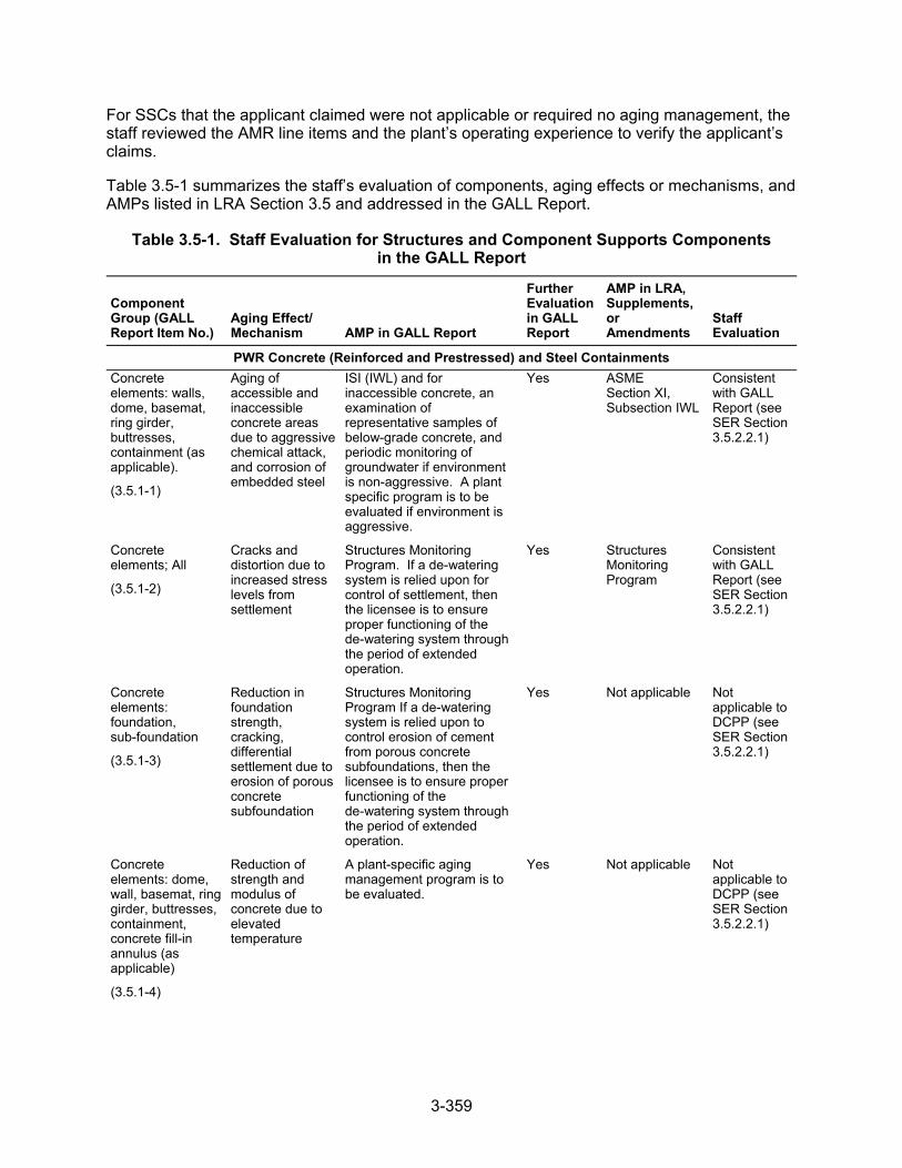
3-359
For SSCs that the applicant claimed were not applicable or required no aging management, the staff reviewed the AMR line items and the plant’s operating experience to verify the applicant’s claims.
Table 3.5-1 summarizes the staff’s evaluation of components, aging effects or mechanisms, and AMPs listed in LRA Section 3.5 and addressed in the GALL Report.
Table 3.5-1. Staff Evaluation for Structures and Component Supports Components in the GALL Report
Component Group (GALL Report Item No.)
Aging Effect/ Mechanism AMP in GALL Report
Further Evaluation in GALL Report
AMP in LRA, Supplements, or Amendments
Staff Evaluation
PWR Concrete (Reinforced and Prestressed) and Steel Containments
Concrete elements: walls, dome, basemat, ring girder, buttresses, containment (as applicable).
(3.5.1-1)
Aging of accessible and inaccessible concrete areas due to aggressive chemical attack, and corrosion of embedded steel
ISI (IWL) and for inaccessible concrete, an examination of representative samples of below-grade concrete, and periodic monitoring of groundwater if environment is non-aggressive. A plant specific program is to be evaluated if environment is aggressive.
Yes ASME Section XI, Subsection IWL
Consistent with GALL Report (see SER Section 3.5.2.2.1)
Concrete elements; All
(3.5.1-2)
Cracks and distortion due to increased stress levels from settlement
Structures Monitoring Program. If a de-watering system is relied upon for control of settlement, then the licensee is to ensure proper functioning of the de-watering system through the period of extended operation.
Yes Structures Monitoring Program
Consistent with GALL Report (see SER Section 3.5.2.2.1)
Concrete elements: foundation, sub-foundation
(3.5.1-3)
Reduction in foundation strength, cracking, differential settlement due to erosion of porous concrete subfoundation
Structures Monitoring Program If a de-watering system is relied upon to control erosion of cement from porous concrete subfoundations, then the licensee is to ensure proper functioning of the de-watering system through the period of extended operation.
Yes Not applicable Not applicable to DCPP (see SER Section 3.5.2.2.1)
Concrete elements: dome, wall, basemat, ring girder, buttresses, containment, concrete fill-in annulus (as applicable)
(3.5.1-4)
Reduction of strength and modulus of concrete due to elevated temperature
A plant-specific aging management program is to be evaluated.
Yes Not applicable Not applicable to DCPP (see SER Section 3.5.2.2.1)
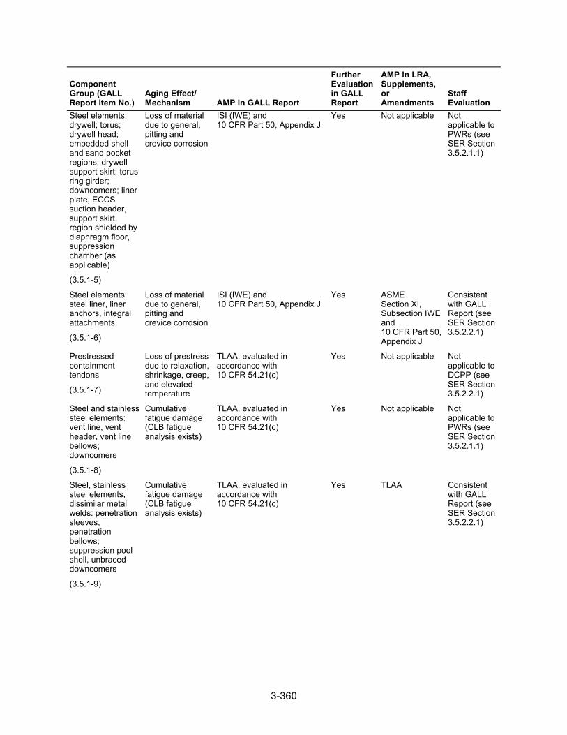
3-360
Component Group (GALL Report Item No.)
Aging Effect/ Mechanism AMP in GALL Report
Further Evaluation in GALL Report
AMP in LRA, Supplements, or Amendments
Staff Evaluation
Steel elements: drywell; torus; drywell head; embedded shell and sand pocket regions; drywell support skirt; torus ring girder; downcomers; liner plate, ECCS suction header, support skirt, region shielded by diaphragm floor, suppression chamber (as applicable)
(3.5.1-5)
Loss of material due to general, pitting and crevice corrosion
ISI (IWE) and 10 CFR Part 50, Appendix J
Yes Not applicable Not applicable to PWRs (see SER Section 3.5.2.1.1)
Steel elements: steel liner, liner anchors, integral attachments
(3.5.1-6)
Loss of material due to general, pitting and crevice corrosion
ISI (IWE) and 10 CFR Part 50, Appendix J
Yes ASME Section XI, Subsection IWE and 10 CFR Part 50, Appendix J
Consistent with GALL Report (see SER Section 3.5.2.2.1)
Prestressed containment tendons
(3.5.1-7)
Loss of prestress due to relaxation, shrinkage, creep, and elevated temperature
TLAA, evaluated in accordance with 10 CFR 54.21(c)
Yes Not applicable Not applicable to DCPP (see SER Section 3.5.2.2.1)
Steel and stainless steel elements: vent line, vent header, vent line bellows; downcomers
(3.5.1-8)
Cumulative fatigue damage (CLB fatigue analysis exists)
TLAA, evaluated in accordance with 10 CFR 54.21(c)
Yes Not applicable Not applicable to PWRs (see SER Section 3.5.2.1.1)
Steel, stainless steel elements, dissimilar metal welds: penetration sleeves, penetration bellows; suppression pool shell, unbraced downcomers
(3.5.1-9)
Cumulative fatigue damage (CLB fatigue analysis exists)
TLAA, evaluated in accordance with 10 CFR 54.21(c)
Yes TLAA Consistent with GALL Report (see SER Section 3.5.2.2.1)
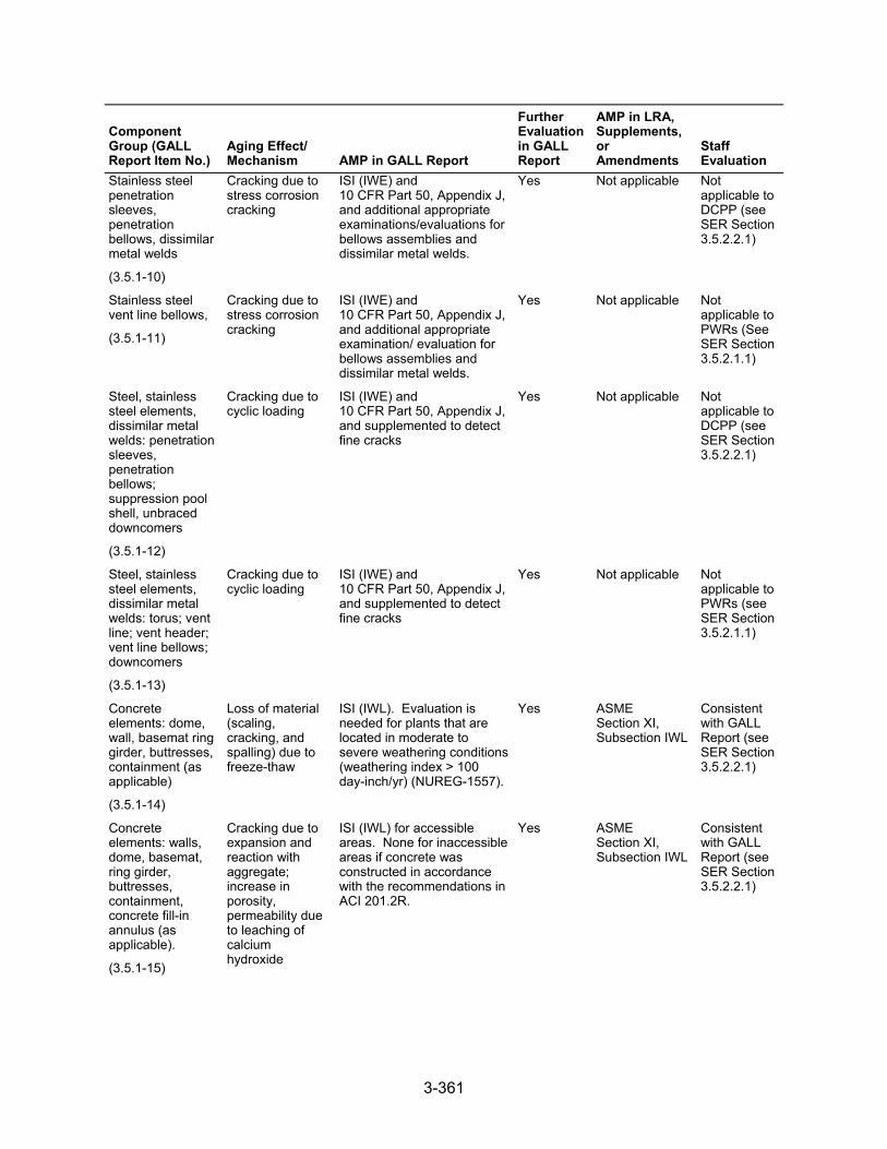
3-361
Component Group (GALL Report Item No.)
Aging Effect/ Mechanism AMP in GALL Report
Further Evaluation in GALL Report
AMP in LRA, Supplements, or Amendments
Staff Evaluation
Stainless steel penetration sleeves, penetration bellows, dissimilar metal welds
(3.5.1-10)
Cracking due to stress corrosion cracking
ISI (IWE) and 10 CFR Part 50, Appendix J, and additional appropriate examinations/evaluations for bellows assemblies and dissimilar metal welds.
Yes Not applicable Not applicable to DCPP (see SER Section 3.5.2.2.1)
Stainless steel vent line bellows,
(3.5.1-11)
Cracking due to stress corrosion cracking
ISI (IWE) and 10 CFR Part 50, Appendix J, and additional appropriate examination/ evaluation for bellows assemblies and dissimilar metal welds.
Yes Not applicable Not applicable to PWRs (See SER Section 3.5.2.1.1)
Steel, stainless steel elements, dissimilar metal welds: penetration sleeves, penetration bellows; suppression pool shell, unbraced downcomers
(3.5.1-12)
Cracking due to cyclic loading
ISI (IWE) and 10 CFR Part 50, Appendix J, and supplemented to detect fine cracks
Yes Not applicable Not applicable to DCPP (see SER Section 3.5.2.2.1)
Steel, stainless steel elements, dissimilar metal welds: torus; vent line; vent header; vent line bellows; downcomers
(3.5.1-13)
Cracking due to cyclic loading
ISI (IWE) and 10 CFR Part 50, Appendix J, and supplemented to detect fine cracks
Yes Not applicable Not applicable to PWRs (see SER Section 3.5.2.1.1)
Concrete elements: dome, wall, basemat ring girder, buttresses, containment (as applicable)
(3.5.1-14)
Loss of material (scaling, cracking, and spalling) due to freeze-thaw
ISI (IWL). Evaluation is needed for plants that are located in moderate to severe weathering conditions (weathering index > 100 day-inch/yr) (NUREG-1557).
Yes ASME Section XI, Subsection IWL
Consistent with GALL Report (see SER Section 3.5.2.2.1)
Concrete elements: walls, dome, basemat, ring girder, buttresses, containment, concrete fill-in annulus (as applicable).
(3.5.1-15)
Cracking due to expansion and reaction with aggregate; increase in porosity, permeability due to leaching of calcium hydroxide
ISI (IWL) for accessible areas. None for inaccessible areas if concrete was constructed in accordance with the recommendations in ACI 201.2R.
Yes ASME Section XI, Subsection IWL
Consistent with GALL Report (see SER Section 3.5.2.2.1)
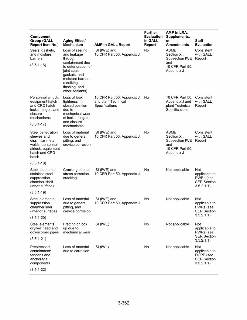
3-362
Component Group (GALL Report Item No.)
Aging Effect/ Mechanism AMP in GALL Report
Further Evaluation in GALL Report
AMP in LRA, Supplements, or Amendments
Staff Evaluation
Seals, gaskets, and moisture barriers
(3.5.1-16)
Loss of sealing and leakage through containment due to deterioration of joint seals, gaskets, and moisture barriers (caulking, flashing, and other sealants)
ISI (IWE) and 10 CFR Part 50, Appendix J
No ASME Section XI, Subsection IWE and 10 CFR Part 50, Appendix J
Consistent with GALL Report
Personnel airlock, equipment hatch and CRD hatch locks, hinges, and closure mechanisms
(3.5.1-17)
Loss of leak tightness in closed position due to mechanical wear of locks, hinges and closure mechanisms
10 CFR Part 50, Appendix J and plant Technical Specifications
No 10 CFR Part 50, Appendix J and plant Technical Specifications
Consistent with GALL Report
Steel penetration sleeves and dissimilar metal welds; personnel airlock, equipment hatch and CRD hatch
(3.5.1-18)
Loss of material due to general, pitting, and crevice corrosion
ISI (IWE) and 10 CFR Part 50, Appendix J
No ASME Section XI, Subsection IWE and 10 CFR Part 50, Appendix J
Consistent with GALL Report
Steel elements: stainless steel suppression chamber shell (inner surface)
(3.5.1-19)
Cracking due to stress corrosion cracking
ISI (IWE) and 10 CFR Part 50, Appendix J
No Not applicable Not applicable to PWRs (see SER Section 3.5.2.1.1)
Steel elements: suppression chamber liner (interior surface)
(3.5.1-20)
Loss of material due to general, pitting, and crevice corrosion
ISI (IWE) and 10 CFR Part 50, Appendix J
No Not applicable Not applicable to PWRs (see SER Section 3.5.2.1.1)
Steel elements: drywell head and downcomer pipes
(3.5.1-21)
Fretting or lock up due to mechanical wear
ISI (IWE) No Not applicable Not applicable to PWRs (see SER Section 3.5.2.1.1)
Prestressed containment: tendons and anchorage components
(3.5.1-22)
Loss of material due to corrosion
ISI (IWL) No Not applicable Not applicable to DCPP (see SER Section 3.5.2.1.1)
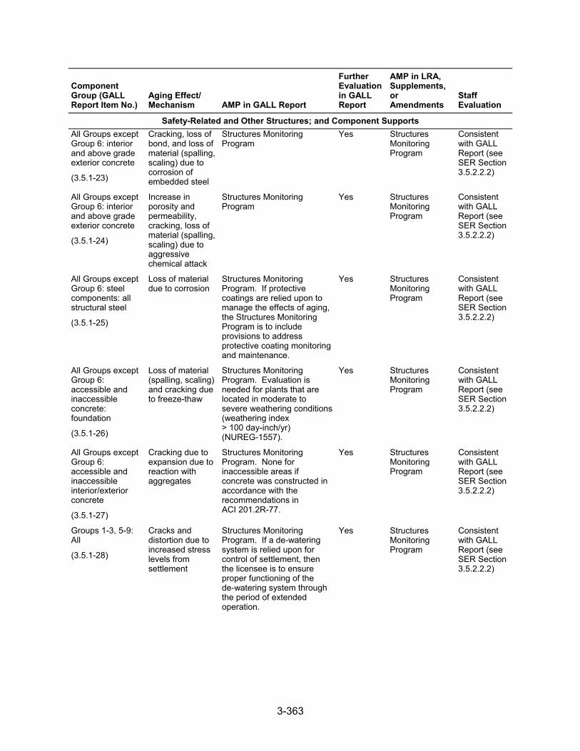
3-363
Component Group (GALL Report Item No.)
Aging Effect/ Mechanism AMP in GALL Report
Further Evaluation in GALL Report
AMP in LRA, Supplements, or Amendments
Staff Evaluation
Safety-Related and Other Structures; and Component Supports
All Groups except Group 6: interior and above grade exterior concrete
(3.5.1-23)
Cracking, loss of bond, and loss of material (spalling, scaling) due to corrosion of embedded steel
Structures Monitoring Program
Yes Structures Monitoring Program
Consistent with GALL Report (see SER Section 3.5.2.2.2)
All Groups except Group 6: interior and above grade exterior concrete
(3.5.1-24)
Increase in porosity and permeability, cracking, loss of material (spalling, scaling) due to aggressive chemical attack
Structures Monitoring Program
Yes Structures Monitoring Program
Consistent with GALL Report (see SER Section 3.5.2.2.2)
All Groups except Group 6: steel components: all structural steel
(3.5.1-25)
Loss of material due to corrosion
Structures Monitoring Program. If protective coatings are relied upon to manage the effects of aging, the Structures Monitoring Program is to include provisions to address protective coating monitoring and maintenance.
Yes Structures Monitoring Program
Consistent with GALL Report (see SER Section 3.5.2.2.2)
All Groups except Group 6: accessible and inaccessible concrete: foundation
(3.5.1-26)
Loss of material (spalling, scaling) and cracking due to freeze-thaw
Structures Monitoring Program. Evaluation is needed for plants that are located in moderate to severe weathering conditions (weathering index > 100 day-inch/yr) (NUREG-1557).
Yes Structures Monitoring Program
Consistent with GALL Report (see SER Section 3.5.2.2.2)
All Groups except Group 6: accessible and inaccessible interior/exterior concrete
(3.5.1-27)
Cracking due to expansion due to reaction with aggregates
Structures Monitoring Program. None for inaccessible areas if concrete was constructed in accordance with the recommendations in ACI 201.2R-77.
Yes Structures Monitoring Program
Consistent with GALL Report (see SER Section 3.5.2.2.2)
Groups 1-3, 5-9: All
(3.5.1-28)
Cracks and distortion due to increased stress levels from settlement
Structures Monitoring Program. If a de-watering system is relied upon for control of settlement, then the licensee is to ensure proper functioning of the de-watering system through the period of extended operation.
Yes Structures Monitoring Program
Consistent with GALL Report (see SER Section 3.5.2.2.2)
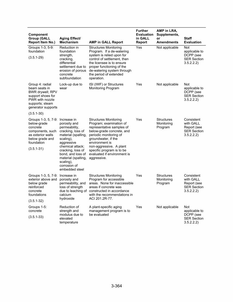
3-364
Component Group (GALL Report Item No.)
Aging Effect/ Mechanism AMP in GALL Report
Further Evaluation in GALL Report
AMP in LRA, Supplements, or Amendments
Staff Evaluation
Groups 1-3, 5-9: foundation
(3.5.1-29)
Reduction in foundation strength, cracking, differential settlement due to erosion of porous concrete subfoundation
Structures Monitoring Program. If a de-watering system is relied upon for control of settlement, then the licensee is to ensure proper functioning of the de-watering system through the period of extended operation.
Yes Not applicable Not applicable to DCPP (see SER Section 3.5.2.2.2)
Group 4: radial beam seats in BWR drywell; RPV support shoes for PWR with nozzle supports; steam generator supports
(3.5.1-30)
Lock-up due to wear
ISI (IWF) or Structures Monitoring Program
Yes Not applicable Not applicable to DCPP (see SER Section 3.5.2.2.2)
Groups 1-3, 5, 7-9: below-grade concrete components, such as exterior walls below grade and foundation
(3.5.1-31)
Increase in porosity and permeability, cracking, loss of material (spalling, scaling), aggressive chemical attack; cracking, loss of bond, and loss of material (spalling, scaling), corrosion of embedded steel
Structures Monitoring Program; examination of representative samples of below-grade concrete, and periodic monitoring of groundwater, if the environment is non-aggressive. A plant specific program is to be evaluated if environment is aggressive.
Yes Structures Monitoring Program
Consistent with GALL Report (see SER Section 3.5.2.2.2)
Groups 1-3, 5, 7-9: exterior above and below grade reinforced concrete foundations
(3.5.1-32)
Increase in porosity and permeability, and loss of strength due to leaching of calcium hydroxide
Structures Monitoring Program for accessible areas. None for inaccessible areas if concrete was constructed in accordance with the recommendations in ACI 201.2R-77.
Yes Structures Monitoring Program
Consistent with GALL Report (see SER Section 3.5.2.2.2)
Groups 1-5: concrete
(3.5.1-33)
Reduction of strength and modulus due to elevated temperature
A plant-specific aging management program is to be evaluated
Yes Not applicable Not applicable to DCPP (see SER Section 3.5.2.2.2)
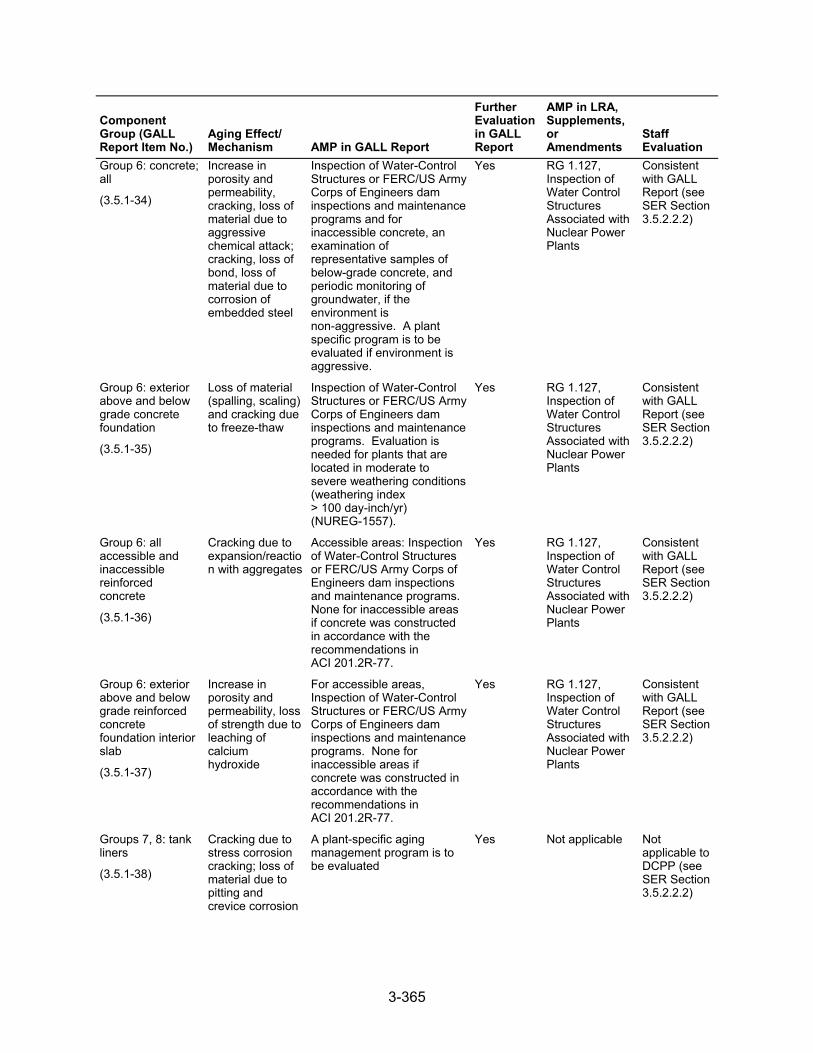
3-365
Component Group (GALL Report Item No.)
Aging Effect/ Mechanism AMP in GALL Report
Further Evaluation in GALL Report
AMP in LRA, Supplements, or Amendments
Staff Evaluation
Group 6: concrete; all
(3.5.1-34)
Increase in porosity and permeability, cracking, loss of material due to aggressive chemical attack; cracking, loss of bond, loss of material due to corrosion of embedded steel
Inspection of Water-Control Structures or FERC/US Army Corps of Engineers dam inspections and maintenance programs and for inaccessible concrete, an examination of representative samples of below-grade concrete, and periodic monitoring of groundwater, if the environment is non-aggressive. A plant specific program is to be evaluated if environment is aggressive.
Yes RG 1.127, Inspection of Water Control Structures Associated with Nuclear Power Plants
Consistent with GALL Report (see SER Section 3.5.2.2.2)
Group 6: exterior above and below grade concrete foundation
(3.5.1-35)
Loss of material (spalling, scaling) and cracking due to freeze-thaw
Inspection of Water-Control Structures or FERC/US Army Corps of Engineers dam inspections and maintenance programs. Evaluation is needed for plants that are located in moderate to severe weathering conditions (weathering index > 100 day-inch/yr) (NUREG-1557).
Yes RG 1.127, Inspection of Water Control Structures Associated with Nuclear Power Plants
Consistent with GALL Report (see SER Section 3.5.2.2.2)
Group 6: all accessible and inaccessible reinforced concrete
(3.5.1-36)
Cracking due to expansion/reaction with aggregates
Accessible areas: Inspection of Water-Control Structures or FERC/US Army Corps of Engineers dam inspections and maintenance programs. None for inaccessible areas if concrete was constructed in accordance with the recommendations in ACI 201.2R-77.
Yes RG 1.127, Inspection of Water Control Structures Associated with Nuclear Power Plants
Consistent with GALL Report (see SER Section 3.5.2.2.2)
Group 6: exterior above and below grade reinforced concrete foundation interior slab
(3.5.1-37)
Increase in porosity and permeability, loss of strength due to leaching of calcium hydroxide
For accessible areas, Inspection of Water-Control Structures or FERC/US Army Corps of Engineers dam inspections and maintenance programs. None for inaccessible areas if concrete was constructed in accordance with the recommendations in ACI 201.2R-77.
Yes RG 1.127, Inspection of Water Control Structures Associated with Nuclear Power Plants
Consistent with GALL Report (see SER Section 3.5.2.2.2)
Groups 7, 8: tank liners
(3.5.1-38)
Cracking due to stress corrosion cracking; loss of material due to pitting and crevice corrosion
A plant-specific aging management program is to be evaluated
Yes Not applicable Not applicable to DCPP (see SER Section 3.5.2.2.2)
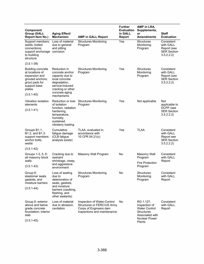
3-366
Component Group (GALL Report Item No.)
Aging Effect/ Mechanism AMP in GALL Report
Further Evaluation in GALL Report
AMP in LRA, Supplements, or Amendments
Staff Evaluation
Support members; welds; bolted connections; support anchorage to building structure
(3.5.1-39)
Loss of material due to general and pitting corrosion
Structures Monitoring Program
Yes Structures Monitoring Program
Consistent with GALL Report (see SER Section 3.5.2.2.2)
Building concrete at locations of expansion and grouted anchors; grout pads for support base plates
(3.5.1-40)
Reduction in concrete anchor capacity due to local concrete degradation, service-induced cracking or other concrete aging mechanisms
Structures Monitoring Program
Yes Structures Monitoring Program
Consistent with GALL Report (see SER Section 3.5.2.2.2)
Vibration isolation elements
(3.5.1-41)
Reduction or loss of isolation function, radiation hardening, temperature, humidity, sustained vibratory loading
Structures Monitoring Program
Yes Not applicable Not applicable to DCPP (see SER Section 3.5.2.2.2)
Groups B1.1, B1.2, and B1.3: support members: anchor bolts, welds
(3.5.1-42)
Cumulative fatigue damage (CLB fatigue analysis exists)
TLAA, evaluated in accordance with 10 CFR 54.21(c)
Yes TLAA Consistent with GALL Report see SER Section 3.5.2.2.2)
Groups 1-3, 5, 6: all masonry block walls
(3.5.1-43)
Cracking due to restraint shrinkage, creep, and aggressive environment
Masonry Wall Program No Masonry Wall Program
Fire Protection Program
Consistent with GALL Report
Group 6: elastomer seals, gaskets, and moisture barriers
(3.5.1-44)
Loss of sealing due to deterioration of seals, gaskets, and moisture barriers (caulking, flashing, and other sealants)
Structures Monitoring Program
No Structures Monitoring Program
Consistent with GALL Report
Group 6: exterior above and below grade concrete foundation; interior slab
(3.5.1-45)
Loss of material due to abrasion, cavitation
Inspection of Water-Control Structures or FERC/US Army Corps of Engineers dam inspections and maintenance
No RG 1.127, Inspection of Water Control Structures Associated with Nuclear Power Plants
Consistent with GALL Report
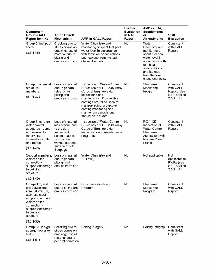
3-367
Component Group (GALL Report Item No.)
Aging Effect/ Mechanism AMP in GALL Report
Further Evaluation in GALL Report
AMP in LRA, Supplements, or Amendments
Staff Evaluation
Group 5: fuel pool liners
(3.5.1-46)
Cracking due to stress corrosion cracking; loss of material due to pitting and crevice corrosion
Water Chemistry and monitoring of spent fuel pool water level in accordance with technical specifications and leakage from the leak chase channels.
No Water Chemistry and monitoring of spent fuel pool water level in accordance with technical specifications and leakage from the leak chase channels.
Consistent with GALL Report
Group 6: all metal structural members
(3.5.1-47)
Loss of material due to general (steel only), pitting and crevice corrosion
Inspection of Water-Control Structures or FERC/US Army Corps of Engineers dam inspections and maintenance. If protective coatings are relied upon to manage aging, protective coating monitoring and maintenance provisions should be included.
No Structures Monitoring Program
Consistent with GALL Report (See SER Section 3.5.2.1.3)
Group 6: earthen water control structures - dams, embankments, reservoirs, channels, canals, and ponds
(3.5.1-48)
Loss of material, loss of form due to erosion, settlement, sedimentation, frost action, waves, currents, surface runoff, Seepage
Inspection of Water-Control Structures or FERC/US Army Corps of Engineers dam inspections and maintenance programs
No RG 1.127, Inspection of Water Control Structures Associated with Nuclear Power Plants
Consistent with GALL Report
Support members; welds; bolted connections; support anchorage to building structure
(3.5.1-49)
Loss of material due to general, pitting, and crevice corrosion
Water Chemistry and ISI (IWF)
No Not applicable Not applicable to PWRs (see SER Section 3.5.2.1.1)
Groups B2, and B4: galvanized steel, aluminum, stainless steel support members; welds; bolted connections; support anchorage to building structure
(3.5.1-50)
Loss of material due to pitting and crevice corrosion
Structures Monitoring Program
No Structures Monitoring Program
Consistent with GALL Report
Group B1.1: high strength low-alloy bolts
(3.5.1-51)
Cracking due to stress corrosion cracking; loss of material due to general corrosion
Bolting Integrity No Bolting Integrity Consistent with GALL Report
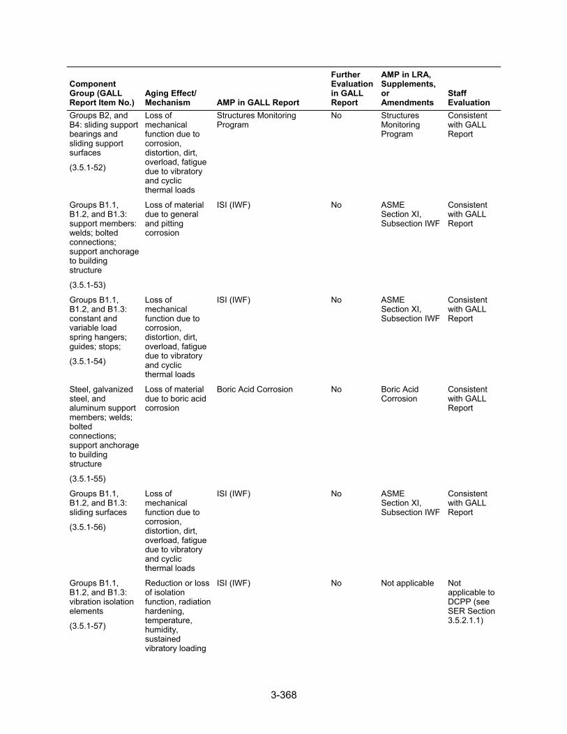
3-368
Component Group (GALL Report Item No.)
Aging Effect/ Mechanism AMP in GALL Report
Further Evaluation in GALL Report
AMP in LRA, Supplements, or Amendments
Staff Evaluation
Groups B2, and B4: sliding support bearings and sliding support surfaces
(3.5.1-52)
Loss of mechanical function due to corrosion, distortion, dirt, overload, fatigue due to vibratory and cyclic thermal loads
Structures Monitoring Program
No Structures Monitoring Program
Consistent with GALL Report
Groups B1.1, B1.2, and B1.3: support members: welds; bolted connections; support anchorage to building structure
(3.5.1-53)
Loss of material due to general and pitting corrosion
ISI (IWF) No ASME Section XI, Subsection IWF
Consistent with GALL Report
Groups B1.1, B1.2, and B1.3: constant and variable load spring hangers; guides; stops;
(3.5.1-54)
Loss of mechanical function due to corrosion, distortion, dirt, overload, fatigue due to vibratory and cyclic thermal loads
ISI (IWF) No ASME Section XI, Subsection IWF
Consistent with GALL Report
Steel, galvanized steel, and aluminum support members; welds; bolted connections; support anchorage to building structure
(3.5.1-55)
Loss of material due to boric acid corrosion
Boric Acid Corrosion No Boric Acid Corrosion
Consistent with GALL Report
Groups B1.1, B1.2, and B1.3: sliding surfaces
(3.5.1-56)
Loss of mechanical function due to corrosion, distortion, dirt, overload, fatigue due to vibratory and cyclic thermal loads
ISI (IWF) No ASME Section XI, Subsection IWF
Consistent with GALL Report
Groups B1.1, B1.2, and B1.3: vibration isolation elements
(3.5.1-57)
Reduction or loss of isolation function, radiation hardening, temperature, humidity, sustained vibratory loading
ISI (IWF) No Not applicable Not applicable to DCPP (see SER Section 3.5.2.1.1)
3-369
Component Group (GALL Report Item No.)
Aging Effect/ Mechanism AMP in GALL Report
Further Evaluation in GALL Report
AMP in LRA, Supplements, or Amendments
Staff Evaluation
Galvanized steel and aluminum support members; welds; bolted connections; support anchorage to building structure exposed to air-indoor uncontrolled
(3.5.1-58)
None None NA None Consistent with GALL Report
Stainless steel support members; welds; bolted connections; support anchorage to building structure
(3.5.1-59)
None None NA None Consistent with GALL Report
The staff’s review of the containment, structures, and component supports component groups followed any one of several approaches. One approach, documented in SER Section 3.5.2.1, reviewed AMR results for components that the applicant noted are consistent with the GALL Report and require no further evaluation. Another approach, documented in SER Section 3.5.2.2, reviewed AMR results for components that the applicant noted are consistent with the GALL Report and for which further evaluation is recommended. A third approach, documented in SER Section 3.5.2.3, reviewed AMR results for components that the applicant noted are not consistent with, or not addressed in, the GALL Report. SER Section 3.0.3 documents the staff’s review of AMPs credited to manage or monitor aging effects of the SC supports components.
3.5.2.1 AMR Results Consistent with the GALL Report
LRA Section 3.5.2.1 notes the materials, environments, AERMs, and the following programs that manage aging effects for the SC supports components:
10 CFR Part 50, Appendix J ASME Section XI, Subsection IWE ASME Section XI, Subsection IWF ASME Section XI, Subsection IWL Bolting Integrity Boric Acid Corrosion Fire Protection Masonry Wall RG 1.127, Inspection of Water-Control Structures Associated with Nuclear Power Plants Structures Monitoring Water Chemistry
3-370
LRA Tables 3.5.2-1 through 3.5.2-14 summarize AMRs for the containment, structures, and component supports components and list AMRs claimed to be consistent with the GALL Report.
As discussed in SER Section 3.0.2.2.2, the applicant provided AMR results which cited generic notes A through J to indicate the AMR’s consistency with the GALL Report. The staff reviewed the information in the LRA for AMRs that the applicant claimed were consistent with the GALL Report (i.e., those AMR items the applicant cited generic notes A through E). The staff did not repeat its review of the matters described in the GALL Report; however, the staff did verify that the material presented in the LRA was applicable and that the applicant identified the appropriate GALL Report AMRs.
The staff reviewed the LRA to confirm that the applicant: (a) provided a brief description of the system, components, materials, and environments; (b) stated that the applicable aging effects were reviewed and evaluated in the GALL Report; and (c) identified those aging effects for the containment, structures, and component supports systems components that are subject to an AMR. For those AMRs that the applicant claimed consistency, the staff compared the LRA AMRs to the corresponding GALL Report AMRs to verify the applicant’s claim of consistency. The staff’s evaluation follows.
3.5.2.1.1 AMR Results Identified as Not Applicable
LRA Table 3.5.1, items 3.5.1.05, 3.5.1.08, 3.5.1.11, 3.5.1.13, 3.5.1.19 through 3.5.1.22, and 3.5.1.49, state that the corresponding AMR items in the GALL Report are not applicable to DCPP because DCPP is a PWR reactor design that incorporates a reinforced concrete containment, and the AMR items in the GALL Report are only applicable to particular components of BWR designs that use a steel containment or containment designs that use a post-tensioning system. The staff verified that the stated AMR items in the GALL Report are only applicable to BWR designs or post-tensioned concrete containments and are not applicable to DCPP.
LRA Table 3.5.1, item 3.5.1.57, states that this item is not applicable to DCPP. The staff reviewed the LRA and FSAR and confirmed that the applicant’s LRA does not have any AMR results that are applicable for this line item.
3.5.2.1.2 Cracking Due to Restraint Shrinkage, Creep, and Aggressive Environment
LRA Table 3.5.1, item 3.5.1.43, addresses concrete block (masonry) walls exposed to plant indoor air, which are managed for cracking. The LRA credits the Fire Protection and Masonry Wall Programs to manage the aging effect. The GALL Report recommends GALL AMP XI.S5, “Masonry Wall Program” to ensure that these aging effects are adequately managed. The associated AMR line items cite generic note E, showing that the LRA AMR is consistent with GALL Report item for material, environment, and aging effect, but a different AMP is credited. For those line items associated with generic note E, GALL AMP XI.S5 recommends using visual inspections to manage the aging effect of these line items. In its review of components associated with LRA Table 3.5.1, item 3.5.1.43, for which the applicant cited generic note E, the staff noted that the Fire Protection Program and Masonry Wall Program propose to manage the aging of concrete block (masonry walls) through the use of visual inspections.
SER Sections 3.0.3.2.5 and 3.0.3.1.18 document the staff’s evaluations of the applicant’s Fire Protection and Masonry Wall Programs, respectively. In its review of components associated with LRA Table 3.5.1, item 3.5.1.43, the staff finds the applicant’s proposal to manage aging using the Fire Protection and Masonry Wall Programs acceptable because the concrete block (masonry) walls are inspected under the Masonry Wall Program, which is consistent with
3-371
GALL AMP XI.S5, the recommended AMP in the GALL Report. The staff noted that the Fire Protection Program is in addition to the GALL Report recommended program, and under this program, the concrete block (masonry) walls outside containment are inspected visually at least once every 18 months, and inside containment at least once every 24 months, for any signs of aging such as cracking, spalling, and loss of material that could lead to loss of fire barrier function.
The staff concludes that the applicant has demonstrated that it will adequately manage the effects of aging for these components so that the intended function(s) will be maintained consistent with the CLB during the period of extended operation, as required by 10 CFR 54.21(a)(3).
3.5.2.1.3 Loss of Material Due to General, Pitting, and Crevice Corrosion
LRA Table 3.5.1, item 3.5.1.47, addresses carbon steel doors; fire barrier doors; penetrations electrical; penetrations mechanical; stairs, platforms, and grates; and structural steel exposed to plant indoor air, atmosphere or weather, or submerged, which are managed for loss of material due to general, pitting, and crevice corrosion. The LRA credits the Structures Monitoring Program to manage the aging effect. The GALL Report recommends GALL AMP XI.S7, “Regulatory Guide 1.127, Inspection of Water-Control Structures Associated with Nuclear Power Plants,” to ensure that these aging effects are adequately managed. The associated AMR line items cite generic note E, indicating that the LRA AMR is consistent with GALL Report item for material, environment, and aging effect, but a different AMP is credited.
For those line items associated with generic note E, GALL AMP XI.S7 recommends using monitoring and inspection to manage the aging effect of these line items. In its review of components associated with LRA Table 3.5.1, item 3.5.1.47, for which the applicant cited generic note E, the staff noted that the Structures Monitoring Program proposes to manage the aging of carbon steel doors; fire barrier doors; penetrations electrical; penetrations mechanical; stairs, platforms, and grates; and structural steel through the use of monitoring and inspection.
SER Section 3.0.3.2.18 documents the staff’s evaluation of the applicant’s Structures Monitoring Program. In its review of components associated with LRA Table 3.5.1, item 3.5.1.47, the staff finds the applicant’s proposal to manage aging using the Structures Monitoring Program acceptable because the carbon steel doors; fire barrier doors; penetrations electrical; penetrations mechanical; stairs, platforms, and grates; and structural steel are monitored and inspected under the Structures Monitoring Program. The applicant’s Structures Monitoring Program carries out RG 1.127, Inspection of Water-Control Structures Associated with Nuclear Power Plants Program, which is consistent with GALL AMP XI.S7 and is identified as the appropriate AMP in the GALL Report.
The staff concludes that the applicant has demonstrated that it will adequately manage the effects of aging for these components so that the intended function(s) will remain consistent with the CLB during the period of extended operation, as required by 10 CFR 54.21(a)(3).
3.5.2.1.4 Conclusion
The staff evaluated the GALL Report AMR items that the applicant claimed were not applicable. On the basis of its review, the staff concludes that the AMR results which the applicant claimed were not applicable.
As discussed in SER Section 3.5.2.1, for those AMRs that the applicant claimed consistency with the GALL Report, the staff evaluated the applicant’s claim of consistency. The staff also
3-372
reviewed information pertaining to the applicant’s consideration of recent operating experience and proposals for managing aging effects. On the basis of its review, the staff concludes that the AMR results, which the applicant claimed to be consistent with the GALL Report, are consistent.
Therefore, the staff concludes that the applicant has demonstrated that the effects of aging for these components will be adequately managed so that their intended function(s) will be maintained consistent with the CLB during the period of extended operation, as required by 10 CFR 54.21(a)(3).
3.5.2.2 AMR Results Consistent with the GALL Report for Which Further Evaluation Is Recommended
In LRA Section 3.5.2.2, the applicant further evaluates aging management, as recommended by the GALL Report, for the containment, structures, and component supports components and provides information concerning how it will manage aging effects in the following three areas:
(1) PWR and BWR containments:
– aging of inaccessible concrete areas
– cracks and distortion due to increased stress levels from settlement; reduction of foundation strength, cracking, and differential settlement due to erosion of porous concrete subfoundations if not covered by the Structures Monitoring Program
– reduction of strength and modulus of concrete structures due to elevated temperature
– loss of material due to general, pitting, and crevice corrosion
– loss of prestress due to relaxation, shrinkage, creep, and elevated temperature
– cumulative fatigue damage
– cracking due to SCC
– cracking due to cyclic loading
– loss of material (scaling, cracking, and spalling) due to freeze-thaw
– cracking due to expansion and reaction with aggregate and increase in porosity and permeability due to leaching of calcium hydroxide
(2) safety-related and other structures and component supports:
– aging of structures not covered by the Structures Monitoring Program
– aging management of inaccessible areas
– reduction of strength and modulus of concrete structures due to elevated temperature
– aging management of inaccessible areas for Group 6 structures
– cracking due to SCC and loss of material due to pitting and crevice corrosion
– aging of supports not covered by the Structures Monitoring Program
– cumulative fatigue damage due to cyclic loading
(3) QA for aging management of nonsafety-related components
3-373
For component groups evaluated in the GALL Report, for which the applicant claimed consistency with the report and for which the report recommends further evaluation, the staff reviewed the applicant’s evaluation to determine if it adequately addressed the issues further evaluated. In addition, the staff reviewed the applicant’s further evaluations against the criteria contained in SRP-LR Section 3.5.2.2. The staff’s review of the applicant’s further evaluation follows.
3.5.2.2.1 PWR and BWR Containments
Aging of Inaccessible Concrete Areas. LRA Section 3.5.2.2.1.1, associated with LRA Table 3.5.1, item 3.5.1.01, addresses aging of accessible and inaccessible concrete areas, which are managed for aggressive chemical attack and corrosion of embedded steel by the ASME Section XI, Subsection IWL Program. The applicant addressed the further evaluation criteria of the SRP-LR by stating that the reinforced concrete structures were designed, constructed, and inspected in accordance with ACI and ASTM standards that provide good quality, dense, well-cured, and low permeability concrete. Crack control was achieved through design requirements that addressed ACI 318-63. In addition, the applicant stated that the groundwater chemistry is monitored and has not been found to be aggressive (i.e., pH greater than 5.5, chlorides less than 500 ppm, and sulfates less than 1500 ppm).
The staff reviewed LRA Section 3.5.2.2.1.1 against the criteria in SRP-LR Section 3.5.2.2.1.1, which states that increases in porosity and permeability, cracking, loss of material (spalling, scaling) due to aggressive chemical attack, and cracking, loss of bond, and loss of material (spalling, scaling) due to corrosion of embedded steel could occur in inaccessible areas of PWR and BWR concrete and steel containments. The GALL report recommends ASME Section XI, Subsection IWL Program to manage these aging effects and recommends further evaluation of plant-specific programs to manage these aging effects for inaccessible areas if the environment is aggressive.
SER Section 3.0.3.1.15 documents the staff’s evaluation of the applicant’s ASME Section XI, Subsection IWL Program. The staff noted that aging management of all accessible areas of the concrete containment building for cracking, loss of material, and increase in porosity and permeability is managed by the ASME Section XI, Subsection IWL Program. The staff also noted that the below-grade environment is non-aggressive and will continue to be monitored for aggressiveness during the period of extended operation. In its review of components associated with LRA Table 3.5.1, item 3.5.1.01, the staff finds the applicant’s proposal to manage aging using the ASME Section XI, Subsection IWL Program acceptable because the ASME Section XI, Subsection IWL Program is the GALL Report recommended program for accessible areas, and the applicant will continue monitoring the below-grade environment for aggressiveness. SER Section 3.5.2.2.2, “Aging Management of Inaccessible Areas,” further documents the staff’s review of the applicant’s evaluation of aging management of inaccessible areas, including the containment-related concrete.
Based on the programs noted, the staff concludes that the applicant’s programs meet SRP-LR Section 3.5.2.2.1.1 criteria. For those line items that apply to LRA Section 3.5.2.2.1.1, the staff determines that the LRA is consistent with the GALL Report and that the applicant has demonstrated that it will adequately manage the effects of aging so that the intended function(s) will be maintained consistent with the CLB during the period of extended operation as required by 10 CFR 54.21(a)(3).
Cracks and Distortion Due to Increased Stress Levels from Settlement; Reduction of Foundation Strength, Cracking, and Differential Settlement Due to Erosion of Porous Concrete Subfoundations, If Not Covered by the Structures Monitoring Program. LRA Section 3.5.2.2.1.2,
3-374
associated with LRA Table 3.5.1, items 3.5.1.02 and 3.5.1.03, addresses concrete components being managed for cracks and distortion due to increased stress levels from settlement as well as reduction of foundation strength, cracking, and differential settlement due to erosion of porous concrete subfoundations, by the Structures Monitoring Program. The applicant addressed the further evaluation criteria of the SRP-LR by stating that the Seismic Category I structures are founded on rock; there are no porous concrete subfoundations.
The staff reviewed LRA Section 3.5.2.2.1.2 against the criteria in SRP-LR Section 3.5.2.2.1.2, which states that cracks and distortion due to increased stress levels from settlement as well as reduction in foundation strength, cracking, and differential settlement due to erosion of porous concrete subfoundations could occur. The GALL report recommends the Structures Monitoring Program to manage these aging effects, and no further evaluation is recommended if this activity is within scope of the Structures Monitoring Program.
SER Section 3.0.3.2.18 documents the staff’s evaluation of the applicant’s Structures Monitoring Program. The staff noted that structures and structural components are monitored under the applicant’s Structures Monitoring Program for aging effects related to settlement. The staff also noted that the applicant does not have porous concrete subfoundations. In its review of components associated with LRA Table 3.5.1, items 3.5.1.02 and 3.5.1.03, the staff finds the applicant’s proposal to manage aging using the Structures Monitoring Program acceptable because this is the GALL Report recommended program, and all necessary components are within the program’s scope.
Based on the programs noted, the staff concludes that the applicant’s programs meet SRP-LR Section 3.5.2.2.1.2 criteria. For those line items that apply to LRA Section 3.5.2.2.1.2, the staff determines that the LRA is consistent with the GALL Report and that the applicant has demonstrated that it will adequately manage the effects of aging so that the intended function(s) will be maintained consistent with the CLB during the period of extended operation, as required by 10 CFR 54.21(a)(3).
Reduction of Strength and Modulus of Concrete Structures Due to Elevated Temperature. LRA Section 3.5.2.2.1.3, associated with LRA Table 3.5.1, item 3.5.1.04, addresses reduction of strength and modulus of concrete structures exposed to elevated temperatures. The GALL Report recommends further evaluation for any concrete elements that exceed the specified temperature limits of 150 °F in general areas, and 200 °F in localized areas. The applicant stated that this line item is not applicable because concrete is not exposed to temperatures above the limits. The applicant further stated that the bearing plates, below the reactor nozzle support shoes, contain cooling water passages to control the temperature of the supporting concrete. The applicant also stated that penetrations for pipes carrying hot fluids are designed to maintain the temperature of the concrete adjacent to the sleeve below 200 °F under normal operating conditions. The HVAC is designed to maintain ambient temperature between 50 °F-120 °F, temperatures of 150 °F or below are maintained in the CRDM shroud area, and temperatures of 135 °F or below are maintained inside the primary concrete shield during normal operation. The staff reviewed LRA Section 2.3.2.4 and FSAR Section 9.4 and confirmed that the containment HVAC system is in-scope for license renewal and that the system is designed to maintain temperatures below 150 °F. Since no in-scope containment concrete is exposed to temperatures exceeding the GALL Report limits, the staff finds the applicant’s determination acceptable.
Loss of Material Due to General, Pitting, and Crevice Corrosion. LRA Section 3.5.2.2.1.4, associated with LRA Table 3.5.1, item 3.5.1.06, addresses steel elements of accessible and inaccessible areas of containments, which are managed for loss of material due to general, pitting, and crevice corrosion by the ASME Section XI, Subsection IWE and 10 CFR Part 50,
3-375
Appendix J Programs. The applicant addressed the further evaluation criteria of the SRP-LR by stating that the ASME Section XI, Subsection IWE and 10 CFR Part 50, Appendix J Programs will manage aging of accessible and inaccessible areas of the containment structure steel elements due to general, pitting, and crevice corrosion. The applicant stated that the ASME Section XI, Subsection IWL Program is used to find and manage any cracks in the concrete that could potentially provide a pathway for water to reach inaccessible portions of the steel containment liner, and procedural controls are in place to ensure that borated water spills are infrequent and, when detected, are cleaned up promptly. In several areas throughout LRA Section 3.5, the applicant stated that the concrete structures were designed and constructed in accordance with ACI 301 and 318.
The staff reviewed LRA Section 3.5.2.2.1.4 against the criteria in SRP-LR Section 3.5.2.2.1.4, which states that loss of material due to general, pitting, and crevice corrosion could occur in steel elements of accessible and inaccessible areas for all types of PWR and BWR containments. The existing program relies on ASME Section XI Subsection IWE and 10 CFR Part 50, Appendix J Programs to manage this aging effect. The GALL Report recommends further evaluation of plant-specific programs to manage this aging effect for inaccessible areas if corrosion is significant. GALL Report, item II.A1-11, states that for inaccessible areas (embedded steel shell or liner) loss of material due to corrosion is not significant if the following four conditions are satisfied:
(1) Concrete meeting the specifications of ACI 318 or 349 and the guidance of ACI 201.2R was used for the containment concrete in contact with the embedded containment shell or liner.
(2) The concrete is monitored to ensure that it is free of penetrating cracks that provide a path for water seepage to the surface of the containment shell or liner.
(3) The moisture barrier, at the junction where the shell or liner becomes embedded, is subject to aging management activities in accordance with ASME Section XI, Subsection IWE requirements.
(4) Borated water spills and water ponding on the containment concrete floor are not common and when detected are cleaned up in a timely manner.
SER Sections 3.0.3.2.18, 3.0.3.2.17, 3.0.3.1.17, and 3.0.3.1.3 document the staff’s review of the applicant’s Structures Monitoring; ASME Section XI, Subsection IWE; 10 CFR Part 50, Appendix J; and Boric Acid Programs, respectively. The staff noted that the concrete mix designs were developed using the guidance provided in ACI 301, which gives specifications for structural concrete that address durability recommendations noted in ACI 201.2R-77. The staff also noted that the applicant had adequately addressed the four conditions discussed in the GALL Report. In its review of components associated with LRA Table 3.5.1, items 3.5.1.05 and 3.5.1.06, the staff finds the applicant’s proposal to manage aging using the above programs acceptable because the applicant is crediting the programs recommended by the GALL Report and has met the criteria for corrosion to be considered insignificant in inaccessible areas.
Based on the programs noted, the staff concludes that the applicant’s programs meet SRP-LR Section 3.5.2.2.1.4 criteria. For those line items that apply to LRA Section 3.5.2.2.1.4, the staff determines that the LRA is consistent with the GALL Report and that the applicant has demonstrated that it will adequately manage the effects of aging so that the intended function(s) will be maintained consistent with the CLB during the period of extended operation, as required by 10 CFR 54.21(a)(3).
Loss of Prestress Due to Relaxation, Shrinkage, Creep, and Elevated Temperature. LRA Section 3.5.2.2.1.5, associated with LRA Table 3.5.1, item 3.5.1.07, addresses loss of prestress
3-376
due to relaxation, shrinkage, creep, and elevated temperature in prestressed containment tendons. The applicant stated that this line item is not applicable because the containment structure does not use a prestressed concrete containment design, so there are no prestressing tendons. The staff finds the applicant’s determination acceptable on the basis that the containment is a reinforced concrete containment with no prestressing tendons.
Based on the above, the staff concludes that SRP-LR Section 3.5.2.2.1.5 criteria do not apply.
Cumulative Fatigue Damage. LRA Section 3.5.2.2.1.6 states that fatigue analyses of penetrations are TLAAs, as defined in 10 CFR 54.3. Applicants must evaluate TLAAs in accordance with 10 CFR 54.21(c)(1). SER Section 4.6.2 documents the staff’s review of the applicant’s evaluation of this TLAA.
Cracking Due to Stress Corrosion Cracking. LRA Section 3.5.2.2.1.7, associated with LRA Table 3.5.1, item 3.5.1.10, addresses stainless steel penetration sleeves, penetration bellows, and dissimilar metal welds. The LRA item also indicates that the GALL Report recommends use of GALL AMP XI.S1, “ASME Section XI, Subsection IWE” and GALL AMP XI.S4, “10 CFR Part 50, Appendix J,” to manage cracking due to SCC for this component group. The applicant stated that this line item is not applicable because there are no in-scope stainless steel penetration sleeves, penetration bellows, or dissimilar metal welds subject to SCC.
The staff reviewed LRA Sections 2.4.1 and 3.5 and confirmed that the applicant’s LRA does not have any AMR results for the structures that include stainless steel penetration sleeves, penetration bellows, or associated dissimilar metal welds. The staff also reviewed the applicant’s FSAR and noted stainless steel flued heads, which appear to be welded to the carbon steel penetration sleeves. The staff noted that this information in the FSAR potentially contradicts the basis of the applicant’s claim that the line item to manage the aging effect due to stress corrosion described in LRA Section 3.5.2.2.1.7 is not applicable. Therefore, by letter dated July 15, 2010, the staff issued RAI 3.5.2.2.1.7-1, asking that the applicant clarify why there are no in-scope stainless steel penetration sleeves, penetration bellows, or dissimilar metal welds subject to SCC, taking into consideration the stainless steel flued heads that are apparently welded to the penetration sleeves.
In its response dated August 12, 2010, the applicant stated that their aging evaluation for the flued head dissimilar weld on the containment penetration concluded that the design and plant configuration prevents a corrosive environment from affecting the dissimilar metal welds. The applicant further stated that the welds are not subject to SCC and do not require an AMP. The applicant stated that the environment inside containment is plant air, which will not corrode the dissimilar metal welds. The applicant further stated that that the welds are protected from spray and dripping by a leak chase. The applicant stated that on the auxiliary building side, the flued head welds are isolated by insulation and a fire protection metal cover. The applicant stated that this configuration on the auxiliary building side is not air tight, but that it does limit the transfer of air to the dissimilar metal welds. The applicant stated that the dissimilar metal welds are tested during the ILRTs, and operating experience has not shown any failures of dissimilar metal welds for this plant configuration. The staff reviewed the applicant’s FSAR and confirmed that the dissimilar metal welds are shielded from corrosion spray or dripping by the leak chase.
Based on its review, the staff finds the applicant’s response to RAI 3.5.2.2.1.7-1 acceptable for the following reasons:
The operating experience has not shown any failures of dissimilar metal welds.
3-377
The operating experience shows that the plant indoor air environment is not corrosive enough to cause SCC.
The leak chase supplies an additional measure to prevent SCC in the dissimilar metal welds of the stainless steel flued heads by protecting the welds from potential corrosive effects of a water leakage event if it occurs.
The staff’s concern described in RAI 3.5.2.2.1.7-1 is resolved.
Based on its review, the staff finds the applicant’s determination that it has no in-scope penetration sleeves, penetration bellows, or dissimilar metal welds subject to SCC to be acceptable.
Based on the above, the staff concludes that SRP-LR Section 3.5.2.2.1.7 criteria do not apply.
Cracking Due to Cyclic Loading. LRA Section 3.5.2.2.1.8, associated with LRA Table 3.5.1, item 3.5.1.12, addresses cracking due to cyclic loading in penetration sleeves and bellows exposed to an air environment. In the LRA, the applicant stated that these line items are not applicable because fatigue of metal components is a TLAA evaluated in accordance with 10 CFR 54.21(c). The staff verified that LRA Section 4.6.2 addresses the fatigue of containment penetrations, and SER Section 4.6.2 documents the staff’s review.
Based on the above, the staff concludes that SRP-LR Section 3.5.2.2.1.8 criteria do not apply.
Loss of Material (Scaling, Cracking, and Spalling) Due to Freeze-Thaw. LRA Section 3.5.2.2.1.9, associated with LRA Table 3.5.1, item 3.5.1.14, addresses loss of material (scaling, cracking, and spalling) in concrete elements due to freeze-thaw. The GALL Report recommends further evaluation of inaccessible areas for plants located in moderate to severe weathering conditions. In the LRA, the applicant stated that DCPP is located in a weathering region classified as “Negligible” according to Figure 1 in ASTM C33-07, and further evaluation for the effects of freeze-thaw evaluation is not required. The staff confirmed that DCPP is located in a weathering region classified as negligible and, therefore, finds the applicant’s determination acceptable.
Based on the above, the staff concludes that SRP-LR Section 3.5.2.2.1.9 criteria do not apply.
Cracking Due to Expansion and Reaction with Aggregate, and Increase in Porosity and Permeability Due to Leaching of Calcium Hydroxide. LRA Section 3.5.2.2.1.10, associated with LRA Table 3.5.1, item 3.5.1.15, addresses cracking due to expansion and reaction with aggregate and increase in porosity and permeability, due to leaching of calcium hydroxide of concrete elements exposed to any environment that are managed for aging by the ASME Section XI, Subsection IWL Program. The applicant addressed the further evaluation criteria of the SRP-LR by stating that petrographic examination of the aggregate material, in accordance with ASTM C295, showed that the aggregate was non-reactive, and further evaluation for the effects of aggregate reactivity is not required. The applicant also stated that the reinforced concrete structures were designed, constructed, and inspected in accordance with ACI and ASTM standards. Concrete mixes were designed in accordance with Method 2, Section 308, of ACI 301, so further evaluation for leaching of calcium hydroxide is not required.
The staff reviewed LRA Section 3.5.2.2.1.10 against the criteria in SRP-LR Section 3.5.2.2.1.10, which states that cracking due to expansion and reaction with aggregate, and increase in porosity and permeability due to leaching of calcium hydroxide, could occur in concrete elements of concrete and steel containments. The GALL Report recommends further evaluation if the aggregate was not evaluated for potential expansion/reaction due to reactivity
3-378
with the cementious materials and recommends the ASME Section XI, Subsection IWL Program. GALL Report Section II.A1-6 notes that an AMP for inaccessible concrete is not required if the concrete was constructed in accordance with the recommendations of ACI 201.2R-77.
SER Section 3.0.3.1.15 documents the staff’s review of the applicant’s ASME Section XI, Subsection IWL Program. In its review of components associated with LRA Table 3.5.1, item 3.5.1.15, the staff finds the applicant’s proposal to manage aging using the ASME Section XI, Subsection IWL Program acceptable because the aggregate materials were evaluated for reactivity in accordance with appropriate ASTM standards. In addition, the concrete mix designs were developed in compliance with guidance provided in ACI 301, which gives specifications for structural concrete that address durability recommendations noted in ACI 201.2R-77.
Based on the programs noted, the staff concludes that the applicant’s programs meet SRP-LR Section 3.5.2.2.1.10 criteria. For those line items that apply to LRA Section 3.5.2.2.1.10, the staff determines that the LRA is consistent with the GALL Report and the applicant has demonstrated that it will adequately manage the effects of aging so that the intended functions will be maintained consistent with the CLB during the period of extended operation, as required by 10 CFR 54.21(a)(3).
3.5.2.2.2 Safety-Related and Other Structures and Component Supports
The staff reviewed LRA Section 3.5.2.2.2 against the criteria in SRP-LR Section 3.5.2.2.2, which address several areas:
Aging of Structures Not Covered by Structures Monitoring Program. LRA Section 3.5.2.2.2.1 addresses aging of structures not covered by the structures monitoring program.
(1) Cracking, Loss of Bond, and Loss of Material (Spalling, Scaling) Due to Corrosion of Embedded Steel for Groups 1–5, 7, and 9 Structures
LRA Section 3.5.2.2.2.1, associated with LRA Table 3.5.1, item 3.5.1.23, addresses cracking, loss of bond, and loss of material (spalling, scaling) due to corrosion of embedded steel for concrete elements of groups 1–5, 7, and 9 structures. The GALL Report recommends further evaluation of this structure and aging effect combination only if it is not covered by the Structures Monitoring Program. In the LRA, the applicant stated that this line item does not require further evaluation because it is covered by the Structures Monitoring Program. The staff confirmed that the structure and aging effect combination is covered by the Structures Monitoring Program and, therefore, finds the applicant’s determination acceptable. SER Section 3.0.3.2.18 documents the staff’s review of the applicant’s Structures Monitoring Program.
(2) Increase in Porosity and Permeability, Cracking, Loss of Material (Spalling, Scaling) Due to Aggressive Chemical Attack for Groups 1–5, 7, and 9 Structures
LRA Section 3.5.2.2.2.1, associated with LRA Table 3.5.1, item 3.5.1.24, addresses increase in porosity and permeability, cracking, and loss of material (spalling, scaling) due to aggressive chemical attack for concrete elements of groups 1–5, 7, and 9 structures. The GALL Report recommends further evaluation of this structure and aging effect combination only if it is not covered by the Structures Monitoring Program. In the LRA, the applicant stated that this line item does not require further evaluation because it is covered by the Structures Monitoring Program. The staff confirmed that the structure and aging effect combination is covered by the Structures Monitoring Program
3-379
and, therefore, finds the applicant’s determination acceptable. SER Section 3.0.3.2.18 documents the staff’s review of the applicant’s Structures Monitoring Program.
(3) Loss of Material Due to Corrosion for Groups 1–5, 7, and 8 Structures
LRA Section 3.5.2.2.2.1, associated with LRA Table 3.5.1, item 3.5.1.25, addresses loss of material due to corrosion for groups 1–5, 7, and 8 structures. The GALL Report recommends further evaluation of this structure and aging effect combination only if it is not covered by the Structures Monitoring Program. In the LRA, the applicant stated that this line item does not require further evaluation because it is covered by the Structures Monitoring Program. The staff confirmed that the structure and aging effect combination is covered by the Structures Monitoring Program and, therefore, finds the applicant’s determination acceptable. SER Section 3.0.3.2.18 documents the staff’s review of the applicant’s Structures Monitoring Program.
(4) Loss of Material (Spalling, Scaling) and Cracking Due to Freeze-Thaw for Groups 1–5 and 7–9 Structures
LRA Section 3.5.2.2.2.1, associated with LRA Table 3.5.1, item 3.5.1.26, addresses loss of material (scaling, cracking, and spalling) in concrete elements due to freeze-thaw. The GALL Report recommends further evaluation for plants located in moderate to severe weathering conditions. In the LRA, the applicant stated that DCPP is located in a weathering region classified as “Negligible,” according to Figure 1 in ASTM C33-07, and no further evaluation is required. The staff confirmed that DCPP is located in a weathering region classified as negligible and, therefore, finds the applicant’s determination acceptable. In addition, the staff confirmed that the Structures Monitoring Program inspects concrete components for spalling and cracking, regardless of aging mechanism. SER Section 3.0.3.2.18 documents the staff’s review of the applicant’s Structures Monitoring Program.
(5) Cracking Due to Expansion and Reaction with Aggregates for Groups 1–5 and 7–9 Structures
LRA Section 3.5.2.2.2.1, associated with LRA Table 3.5.1, item 3.5.1.27, addresses cracking due to expansion due to reaction with aggregates for groups 1–5 and 7–9 structures. The GALL Report recommends further evaluation of this structure and aging effect combination only if it is not covered by the Structures Monitoring Program. In the LRA, the applicant stated that this line item does not require further evaluation because it is covered by the Structures Monitoring Program. The staff confirmed that the structure and aging effect combination is covered by the Structures Monitoring Program and, therefore, finds the applicant’s determination acceptable. SER Section 3.0.3.2.18 documents the staff’s review of the applicant’s Structures Monitoring Program.
(6) Cracks and Distortion Due to Increased Stress Levels from Settlement for Groups 1–3 and 5–9 Structures
LRA Section 3.5.2.2.2.1, associated with LRA Table 3.5.1, item 3.5.1.28, addresses cracks and distortion due to increased stress levels from settlement for groups 1–3 and 5–9 structures. The GALL Report recommends further evaluation of this structure and aging effect combination only if it is not covered by the Structures Monitoring Program. In the LRA, the applicant stated that this line item does not require further evaluation because the seismic Category I structures and structures housing design Class I equipment are founded on rock. The staff reviewed the FSAR and confirmed that Class I structures are founded on bedrock. In addition, the staff noted that the applicant’s Structures Monitoring Program inspects for cracking, regardless of aging mechanism; therefore, the staff finds the applicant’s determination acceptable. SER
3-380
Section 3.0.3.2.18 documents the staff’s review of the applicant’s Structures Monitoring Program.
(7) Reduction in Foundation Strength, Cracking, and Differential Settlement Due to Erosion of Porous Concrete Subfoundation for Groups 1–3 and 5–9 Structures
LRA Section 3.5.2.2.2.1, associated with LRA Table 3.5.1, item 3.5.1.29, addresses reduction in foundation strength, cracking, and differential settlement due to erosion of porous concrete subfoundations for groups 1–3 and 5–9 structures. The applicant stated that this line item is not applicable because porous concrete subfoundations were not used at DCPP. The staff reviewed the FSAR and confirmed that no porous concrete subfoundations are present at DCPP; therefore, the staff finds that applicant’s determination acceptable.
(8) Lock up Due to Wear for Lubrite® Radial Beam Seats in BWR Drywell and Other Sliding Support Surfaces
LRA Section 3.5.2.2.2.1, associated with LRA Table 3.5.1, item 3.5.1.30, addresses lock-up due to wear in Lubrite® supports exposed to an air-indoor environment. The GALL Report recommends further evaluation of this structure and aging effect combination only if it is not covered by the Structures Monitoring Program or the IWF Program. The applicant stated that this line item is not applicable because Lubrite® is not used on the RPV shoes or SG supports, and all in-scope sliding surfaces are evaluated under the Structures Monitoring Program or the ASME Section XI, Subsection IWF Program. The staff reviewed the FSAR and confirmed that the applicant has no Lubrite® supports associated with the RPV or SGs. In addition, the staff noted that the applicant’s Structures Monitoring Program or IWF Program inspects for lock-up; therefore, the staff finds the applicant’s determination acceptable. SER Sections 3.0.3.2.16 and 3.0.3.2.18 document the staff’s review of the applicant’s ASME Section XI, Subsection IWF and Structures Monitoring Programs, respectively.
Based on the above, the staff concludes that SRP-LR Section 3.5.2.2.2.1 criteria do not apply.
Aging Management of Inaccessible Areas. LRA Section 3.5.2.2.2.2 addresses aging management of inaccessible areas (below-grade inaccessible concrete areas of Groups 1–3, 5, and 7–9 structures):
(1) Loss of material (spalling, scaling) and cracking due to freeze-thaw could occur in below-grade inaccessible concrete areas of Groups 1–3, 5 and 7–9 structures.
LRA Section 3.5.2.2.2.2.1, associated with LRA Table 3.5.1, item 3.5.1.26, addresses loss of material (scaling, cracking, and spalling) of inaccessible concrete elements due to freeze-thaw. The GALL Report recommends further evaluation for plants located in moderate to severe weathering conditions. The applicant stated that DCPP is located in a weathering region classified as “Negligible,” according to Figure 1 in ASTM C33-07, and no further evaluation is required. The staff confirmed that DCPP is located in a weathering region classified as negligible and, therefore, finds the applicant’s determination acceptable.
(2) Cracking due to expansion and reaction with aggregates could occur in below-grade inaccessible concrete areas for Groups 1–5 and 7–9 structures.
LRA Section 3.5.2.2.2.2.2, associated with LRA Table 3.5.1, item 3.5.1.27, addresses cracking due to expansion due to reaction with aggregates for Groups 1-5, and 7-9 structures. The GALL Report states that further evaluation of this structure and aging effect combination for inaccessible areas is not necessary if examinations performed in accordance with ASTM standards C295 or C227 had demonstrated that the aggregates
3-381
are non-reactive. In the LRA, the applicant stated that this line item does not require further evaluation because acceptance of aggregates was based, in part, on petrographic examination in accordance with ASTM C295. The staff reviewed the FSAR and confirmed that aggregates were tested for reactivity in accordance with ASTM C295; therefore, the staff finds acceptable the applicant’s determination that further evaluation is not required.
(3) Cracks and distortion due to increased stress levels from settlement and reduction of foundation strength, cracking, and differential settlement due to erosion of porous concrete subfoundations could occur in below-grade inaccessible concrete areas of Groups 1-3, 5, and 7-9 structures.
LRA Section 3.5.2.2.2.2.3, associated with LRA Table 3.5.1, items 3.5.1.28 and 3.5.1.29, addresses cracks and distortion due to increased stress levels from settlement and reduction in foundation strength, cracking, and differential settlement due to erosion of porous concrete subfoundations for Groups 1-3 and 5-9 structures. The GALL Report recommends no further evaluation if this activity and these aging effects are included in the scope of the applicant’s Structures Monitoring Program and no dewatering system is used. In the LRA, the applicant stated that these line items do not require further evaluation because the seismic Category I structures and structures housing design Class I equipment are founded on rock, and no porous subfoundations exist. The staff reviewed the FSAR and confirmed that Class I structures are founded on bedrock, a dewatering system is not used, and there are no porous subfoundations on the site. In addition, the staff noted that the applicant’s Structures Monitoring Program inspects for cracking, regardless of aging mechanism. Therefore, the staff finds acceptable the applicant’s determination that further evaluation is not required. SER Section 3.0.3.2.18 documents the staff’s review of the applicant’s Structures Monitoring Program.
(4) Increase in porosity and permeability, cracking and loss of material (spalling, scaling) due to aggressive chemical attack, and cracking, loss of bond, and loss of material (spalling, scaling) due to corrosion of embedded steel could occur in below-grade inaccessible concrete areas of Groups 1-3, 5, and 7-9 structures.
LRA Section 3.5.2.2.2.2.4 associated with LRA Table 3.5.1, item 3.5.1.31, addresses below-grade concrete components exposed to a groundwater or soil environment, which are managed for cracking, loss of material, and loss of bond due to aggressive chemical attack and corrosion of embedded steel. The applicant addressed the further evaluation criteria of the SRP-LR by stating that the reinforced concrete structures were designed, constructed, and inspected in accordance with ACI and ASTM standards that provide good quality, dense, well-cured, and low permeability concrete. Crack control was achieved through design requirements that addressed ACI 318-63. The applicant further stated that the groundwater chemistry was monitored monthly from August 2008–July 2009 and has not been found to be aggressive (i.e., pH greater than 5.5, chlorides less than 500 ppm, and sulfates less than 1500 ppm). The applicant further stated that it will enhance the Structures Monitoring Program to monitor groundwater during the period of extended operation, on an interval not to exceed 5 years.
The staff reviewed LRA Section 3.5.2.2.2.2.4 against the criteria in SRP-LR Section 3.5.2.2.2.2, item 4, which states that the GALL Report recommends further evaluation of plant-specific programs to manage these aging effects and mechanisms in inaccessible areas of these groups of structures if the environment is aggressive. In the GALL Report, it is noted that for inaccessible areas of plants with non-aggressive groundwater or soil (i.e., pH greater than 5.5, chlorides less than 500 ppm, or sulfates less than 1500 ppm), as a minimum, the following should be considered:
3-382
– examinations of the exposed portions of the below-grade concrete, when excavated for any reason
– periodic monitoring of below-grade water chemistry, including consideration of potential seasonal variations
In its review of components associated with LRA Table 3.5.1, item 3.5.1.31, the staff noted that groundwater sample results had been monitored monthly at the DCPP power block locations from August 2008–July 2009. Although the groundwater chemistry indicates that it is non-aggressive, the results were not sufficient to be representative of seasonal variations that might occur. In addition, although DCPP is located in a coastal environment (e.g., high chlorides), the applicant did not note any plans for opportunistic inspections of below-grade structures, as noted in the GALL Report. Since the applicant does not have definite plans for inspections of inaccessible areas, and DCPP is located in a coastal environment, it is unclear to the staff that this is an adequate approach to managing aging of inaccessible concrete structures subjected to a potentially aggressive environment that could produce corrosion of embedded steel in the reinforced concrete structures. By letter dated June 21, 2010, the staff issued RAI B2.1.32-3, asking that the applicant give locations and historical values of the groundwater samples, as well as any future plans to conduct opportunistic inspections of below-grade structures.
In its response dated July 19, 2010, the applicant gave the locations of the sampling wells and historic groundwater analysis values, which were within the limits for non-aggressive groundwater. The applicant also committed to evaluate reinforced concrete whenever it is exposed during excavations (Commitment No. 34). The staff finds the applicant’s response acceptable because it demonstrates that the groundwater is non-aggressive, and the applicant’s commitment aligns their program with the guidance in the GALL Report. The staff’s concern described in RAI B2.1.32-3 is resolved. The Structure Monitoring Program Evaluation, in SER Section 3.0.3.2.18, documents a more detailed discussion of the groundwater issue and the RAI.
The staff finds the applicant’s proposal to manage aging using the Structures Monitoring Program acceptable because the groundwater is non-aggressive, and the applicant’s program incorporates the GALL Report recommendations for this item, including groundwater monitoring at least every 5 years and opportunistic inspections of below-grade concrete.
(5) Increase in porosity and permeability, and loss of strength due to leaching of calcium hydroxide, could occur in below-grade inaccessible concrete areas of Groups 1–3, 5, and 7–9 structures
LRA Section 3.5.2.2.2.2.5, associated with LRA Table 3.5.1, item 3.5.1.32, addresses below-grade concrete components exposed to a flowing water or soil environment, which are managed for increase in porosity and permeability and loss of strength due to leaching of calcium hydroxide. The applicant addressed the further evaluation criteria of the SRP-LR by stating that the reinforced concrete structures were designed, constructed, and inspected in accordance with ACI and ASTM standards. Concrete mixes were designed in accordance with Method 2, Section 308, of ACI 301, so further evaluation for leaching of calcium hydroxide is not required.
The staff reviewed LRA Section 3.5.2.2.2.2.5 against the criteria in SRP-LR Section 3.5.2.2.2.2, item 5, which states that the GALL Report recommends further evaluation of this aging effect for inaccessible areas of Groups 1-3, 5 and 7-9 structures, if concrete was not constructed in accordance with the recommendations in ACI 201.2R-77.
3-383
In its review of components associated with line item 3.5.1.32, the staff finds the applicant’s further evaluation acceptable because the concrete mix designs were developed using the guidance provided in ACI 301, which contains specifications for structural concrete that address durability recommendations noted in ACI 201.2R-77.
Based on the programs noted above, the staff concludes that the applicant’s programs meet SRP-LR Section 3.5.2.2.2.2 criteria. For those line items that apply to LRA Section 3.5.2.2.2.2, the staff determines that the LRA is consistent with the GALL Report and that the applicant has demonstrated that it will adequately manage the effects of aging so that the intended function(s) will be maintained consistent with the CLB during the period of extended operation, as required by 10 CFR 54.21(a)(3).
Reduction of Strength and Modulus of Concrete Structures Due to Elevated Temperature. LRA Section 3.5.2.2.2.3, associated with LRA Table 3.5.1, item 3.5.1.33, addresses reduction of strength and modulus of concrete structures exposed to elevated temperatures. The GALL Report recommends further evaluation for any concrete elements that exceed the specified temperature limits of 150 °F general and 200 °F local. The applicant stated that this line item is not applicable because concrete is not exposed to temperatures above the limits. The applicant further stated that the HVAC system is designed to maintain indoor temperatures below 150 °F and penetrations for pipes carrying hot fluids are designed to maintain the temperature of the concrete adjacent to the sleeve below 200 °F under normal operating conditions. The staff reviewed the FSAR and confirmed that no in-scope concrete is exposed to temperatures exceeding the GALL Report limits and, therefore, finds the applicant’s determination acceptable.
Based on the above, the staff concludes that SRP-LR Section 3.5.2.2.2.3 criteria do not apply.
Aging Management of Inaccessible Areas for Group 6 Structures. The staff reviewed LRA Section 3.5.2.2.2.4 against the following criteria in SRP-LR Section 3.5.2.2.2.4:
(1) Increase in porosity and permeability, cracking, loss of material (spalling, scaling) due to aggressive chemical attack and cracking, loss of bond, and loss of material (spalling, scaling) due to corrosion of embedded steel could occur in below-grade inaccessible concrete areas of Group 6 structures.
LRA Section 3.5.2.2.2.4.1 associated with LRA Table 3.5.1, item 3.5.1.34, addresses below-grade concrete components exposed to a groundwater or soil environment, which are being managed for increase in porosity and permeability, cracking, loss of material, and loss of bond due to aggressive chemical attack and corrosion of embedded steel. The applicant addressed the further evaluation criteria of the SRP-LR by stating that the reinforced concrete structures were designed, constructed, and inspected in accordance with ACI and ASTM standards that provide good quality, dense, well-cured, and low-permeability concrete. Crack control was achieved through design requirements that addressed ACI 318-63. The applicant further stated that the groundwater chemistry is monitored at DCPP and has not been found to be aggressive (i.e., pH greater than 5.5, chlorides less than 500 ppm, and sulfates less than 1500 ppm).
The staff reviewed LRA Section 3.5.2.2.2.4.1 against the criteria in SRP-LR Section 3.5.2.2.2.4, item 1, which states that the GALL Report recommends further evaluation of plant-specific programs to manage these aging effects in inaccessible areas if the environment is aggressive. In the GALL Report, it is noted that for inaccessible areas of plants with non-aggressive groundwater or soil (i.e., pH greater than 5.5, chlorides less than 500 ppm, or sulfates less than 1500 ppm), as a minimum the following should be considered:
3-384
– examinations of the exposed portions of the below-grade concrete, when excavated for any reason
– periodic monitoring of below-grade water chemistry, including consideration of potential seasonal variations
SER Section 3.5.2.2.2, Subsection “Aging of Inaccessible Areas,” item 4, documents the staff’s review of the adequacy of the applicant’s aging management approach for these aging effects on inaccessible elements of reinforced concrete structures.
(2) Loss of material (spalling, scaling) and cracking due to freeze-thaw that could occur in below-grade inaccessible concrete areas of Group 6 structures.
LRA Section 3.5.2.2.2.4.2, associated with LRA Table 3.5.1, item 3.5.1.35, addresses loss of material (scaling, cracking, and spalling) of inaccessible concrete elements due to freeze-thaw in Group 6 structures. The GALL Report recommends further evaluation for plants located in moderate to severe weathering conditions. The applicant stated that this line item is not applicable because DCPP is located in a weathering region classified as “Negligible,” according to Figure 1 in ASTM C33-07, and no further evaluation is required. The staff confirmed that DCPP is located in a weathering region classified as negligible and, therefore, finds the applicant’s determination acceptable.
(3) Cracking due to expansion and reaction with aggregates and increase in porosity and permeability, and loss of strength due to leaching of calcium hydroxide, could occur in below-grade inaccessible reinforced concrete areas of Group 6 structures.
LRA Section 3.5.2.2.2.4.3, associated with LRA Table 3.5.1, item 3.5.1.36, addresses cracking due to reaction with aggregates for Group 6 structures. The GALL Report states that further evaluation of this structure and aging effect combination for inaccessible areas is not necessary if examinations, performed in accordance with ASTM standards C295 or C227, demonstrated that the aggregates are non-reactive. In the LRA, the applicant stated that this line item does not require further evaluation because acceptance of aggregates was based, in part, on petrographic examination in accordance with ASTM C295. The staff reviewed the FSAR and confirmed that aggregates were tested for reactivity in accordance with ASTM C295; therefore, the staff finds acceptable the applicant’s determination that further evaluation is not required.
LRA Section 3.5.2.2.2.4.3, associated with LRA Table 3.5.1, item 3.5.1.37, addresses below-grade concrete components exposed to a flowing water or soil environment, which are managed for increase in porosity and permeability as well as loss of strength due to leaching of calcium hydroxide. The applicant addressed the further evaluation criteria of the SRP-LR by stating that the reinforced concrete structures were designed, constructed, and inspected in accordance with ACI and ASTM standards. Concrete mixes were designed in accordance with Method 2, Section 308, of ACI 301; so, further evaluation for leaching of calcium hydroxide is not required.
The staff reviewed LRA Section 3.5.2.2.2.4.3 against the criteria in SRP-LR Section 3.5.2.2.2.4, item 3, which states that the GALL Report recommends further evaluation of these aging effects for inaccessible areas of Group 6 structures if concrete was not constructed in accordance with the recommendations in ACI 201.2R-77.
In its review of components associated with LRA Table 3.5.1, items 3.5.1.36 and 3.5.1.37, the staff finds the applicant’s further evaluation acceptable because the concrete mix designs were developed using the guidance provided in ACI 301, which contains specifications for structural concrete that address durability recommendations identified in ACI 201.2R-77.
3-385
Based on the programs noted above, the staff concludes that the applicant’s programs meet SRP-LR Section 3.5.2.2.2.4 criteria. For those line items that apply to LRA Section 3.5.2.2.2.4, the staff determines that the LRA is consistent with the GALL Report and that the applicant has demonstrated that it will adequately manage the effects of aging so that the intended function(s) will be maintained consistent with the CLB during the period of extended operation, as required by 10 CFR 54.21(a)(3).
Cracking Due to Stress Corrosion Cracking and Loss of Material Due to Pitting and Crevice Corrosion. The staff reviewed LRA Section 3.5.2.2.2.5 against the criteria in SRP-LR Section 3.5.2.2.2.5.
LRA Section 3.5.2.2.2.5, associated with LRA Table 3.5.1, item 3.5.1.38, addresses cracking due to SCC and loss of material due to pitting and crevice corrosion for Group 7 and 8 stainless steel tank liners. The applicant stated that this line item is not applicable because the in-scope tank liners were evaluated as tanks with their mechanical systems and assigned lines from GALL Report Chapters VII and VIII. The staff reviewed LRA Sections 3.1 through 3.4 and confirmed that the in-scope tank liners were evaluated as tanks with their mechanical systems and assigned lines from GALL Report Chapters VII and VIII.
Based on the above, the staff concludes that SRP-LR Section 3.5.2.2.2.5 criteria do not apply.
Aging of Supports Not Covered by the Structures Monitoring Program. LRA Section 3.5.2.2.2.6 addresses aging of supports not covered by Structures Monitoring Program.
(1) Loss of Material Due to General and Pitting Corrosion, for Groups B2-B5 Supports
LRA Section 3.5.2.2.2.6, associated with LRA Table 3.5.1, item 3.5.1.39, addresses loss of material due to general and pitting corrosion of groups B2–B5 steel supports exposed to an air environment. The GALL Report recommends further evaluation of this structure and aging effect combination, only if it is not covered by the Structures Monitoring Program. In the LRA, the applicant stated that this line item does not require further evaluation because it is covered by the Structures Monitoring Program. The staff confirmed that the structure and aging effect combination is covered by the Structures Monitoring Program and, therefore, finds the applicant’s determination acceptable. SER Section 3.0.3.2.18 documents the staff’s review of the applicant’s Structures Monitoring Program.
(2) Reduction in Concrete Anchor Capacity Due to Degradation of the Surrounding Concrete for Groups B1–B5 Supports
LRA Section 3.5.2.2.2.6, associated with LRA Table 3.5.1, item 3.5.1.40, addresses reduction in anchor capacity due to degradation of surrounding concrete for groups B1–B5 supports exposed to an air environment. The GALL Report recommends further evaluation of this structure and aging effect combination, only if it is not covered by the Structures Monitoring Program. In the LRA, the applicant stated that this line item does not require further evaluation because it is covered by the Structures Monitoring Program. The staff confirmed that the structure and aging effect combination is covered by the Structures Monitoring Program and, therefore, finds the applicant’s determination acceptable. SER Section 3.0.3.2.18 documents the staff’s review of the applicant’s Structures Monitoring Program.
(3) Reduction/Loss of Isolation Function Due to Degradation of Vibration Isolation Elements for Group B4 Supports
3-386
LRA Section 3.5.2.2.2.6, associated with LRA Table 3.5.1, item 3.5.1.41, addresses reduction of isolation function of non-metallic vibration isolation elements in an air environment. In the LRA, the applicant stated that this line item is not applicable because there are no vibration isolation elements within the scope of license renewal. The staff reviewed LRA Sections 2 and 3 and the FSAR and confirmed that there are no in-scope vibration isolation elements. Therefore, the staff finds the applicant’s determination acceptable.
Based on the above, the staff concludes that SRP-LR Section 3.5.2.2.2.6 criteria do not apply.
Cumulative Fatigue Damage Due to Cyclic Loading. LRA Section 3.5.2.2.2.7 states that analyses of fatigue of component support members, anchor bolts, and welds for Group B1.1, Group B1.2, and Group B1.3 component supports (for ASME Code Class 1, 2, and 3 piping and components and for Class MC BWR containment supports) are TLAAs, as defined in 10 CFR 54.3, only if a CLB fatigue analysis exists. The applicant did not note any TLAAs supporting design of these components. The applicant also stated that ASME Code Class 1 piping is designed to code editions and addenda before 1986, which prevents cycle limits for allowable stress in supports, and Section 4.3.2.7 addresses further evaluation of these component supports. This is consistent with SRP-LR Section 3.5.2.2.2.7 and is, therefore, acceptable.
3.5.2.2.3 Quality Assurance for Aging Management of Nonsafety-Related Components
SER Section 3.0.4 documents the staff’s evaluation of the applicant’s QA program.
3.5.2.3 AMR Results Not Consistent with or Not Addressed in the GALL Report
In LRA Tables 3.5.2-1 through 3.5.2-14, the staff reviewed additional details of the AMR results for material, environment, AERM, and AMP combinations not consistent with, or not addressed in, the GALL Report.
In LRA Tables 3.5.2-1 through 3.5.2-14, via notes F through J, the applicant noted which combinations of component type, material, environment, and AERM do not correspond to a line item in the GALL Report. The applicant gave further information about how it will manage the aging effects. Specifically, note F indicates that the material for the AMR line item component is not evaluated in the GALL Report. Note G indicates that the environment for the AMR line item component and material is not evaluated in the GALL Report. Note H indicates that the aging effect for the AMR line item component, material, and environment combination is not evaluated in the GALL Report. Note I indicates that the aging effect identified in the GALL Report for the line item component, material, and environment combination is not applicable. Note J indicates that neither the component nor the material and environment combination for the line item is evaluated in the GALL Report.
For component type, material, and environment combinations not evaluated in the GALL Report, the staff reviewed the applicant’s evaluation to determine if the applicant has demonstrated that it will adequately manage the effects of aging so that the intended function(s) will be maintained consistent with the CLB for the period of extended operation. The following sections document the staff’s evaluation.
3.5.2.3.1 Containment Building—Summary of Aging Management Review—LRA Table 3.5.2-1
The staff reviewed LRA Table 3.5.2-1, which summarizes the results of AMR evaluations for the containment building component groups.
3-387
In LRA Tables 3.5.2-1 and 3.5.2-4, the applicant stated that the external surfaces of fire barrier coatings and wraps (i.e., ceramic fiber or cementitious coating), and gypsum and plaster barriers exposed to indoor air, are managed for loss of material and cracking by the Fire Protection Program. The AMR items cite generic note J, indicating that neither the component nor the material and environment combination for the line item is evaluated in the GALL Report. SER Section 3.0.3.2.5 documents the staff’s evaluation of the Fire Protection Program. In its review of the AMR line items, the staff noted that the aging effect noted by the applicant is applicable for this combination of component, material, and environment. The staff also noted that the applicant’s Fire Protection Program includes visual inspections of fire barriers to detect any signs of aging degradation such as cracking, spalling, and loss of material. The staff further noted that the program states that all fire barrier walls, ceilings, floors, coatings, and wraps are inspected at least once every 18 months if they are outside containment or at least once every 24 months if they are inside containment. The staff finds the applicant’s proposal acceptable because the applicant has noted applicable aging effects and has chosen an AMP that contains appropriate inspection techniques to find those aging effects and adequately addresses the selection and frequency of inspections.
Based on its review, the staff finds that the applicant has appropriately evaluated the AMR results of material, environment, AERM, and AMP combinations not evaluated in the GALL Report. The staff finds that the applicant has demonstrated that it will adequately manage the effects of aging so that the intended function(s) will be maintained consistent with the CLB for the period of extended operation, as required by 10 CFR 54.21(a)(3).
3.5.2.3.2 Control Room—Summary of Aging Management Review—LRA Table 3.5.2-2
The staff reviewed LRA Table 3.5.2-2, which summarizes the results of AMR evaluations for the control room component groups. The staff's review did not note any line items with notes F through J, indicating that the combinations of component type, material, environment, and AERM for this system are consistent with the GALL Report.
SER Section 3.5.2.1 documents the staff's evaluation of the line items with notes A through E.
3.5.2.3.3 Auxiliary Building—Summary of Aging Management Review—Table 3.5.2-3
The staff reviewed LRA Table 3.5.2-3, which summarizes the results of AMR evaluations for the auxiliary building component groups.
In LRA Tables 3.5.2-3, 3.5.2-8, and 3.5.2-9, the applicant stated that gypsum and plaster barriers exposed to plant indoor air are managed for cracking by the Structures Monitoring Program. The AMR line item cites generic note J. The staff reviewed the associated line items in the LRA and confirmed that the applicant has noted the correct aging effects for this component, material, and environment combination. SER Section 3.0.3.2.18 documents the staff’s evaluation of the Structures Monitoring Program. The staff finds the applicant’s proposal to manage aging using the Structures Monitoring Program acceptable because the condition of the gypsum and plaster components, that provide either a shelter and protection or structural pressure boundary function, are inspected visually for cracking and loss of material in accordance with methods, inspection schedule, and inspector qualifications that are consistent with ACI 349.3R-96 and ASCE 11-90. The inspection method and frequency align with the recommendations of the GALL Report.
In LRA Table 3.5.2-3, the applicant stated that cementitious fire barrier coatings and wraps exposed to plant indoor air are managed for loss of material and cracking by the Fire Protection Program. The AMR line item cites generic note J. The staff reviewed the associated line items
3-388
in the LRA and confirmed that the applicant has noted the correct aging effects for this component, material, and environmental combination because cementitious fire barriers have similar properties to concrete fire barriers, which, per the GALL Report, can experience loss of material and cracking when exposed to indoor air. SER Section 3.0.3.2.5 documents the staff’s evaluation of the applicant’s Fire Protection Program. The staff finds the applicant’s proposed program acceptable to manage aging for these components because the program includes periodic visual inspections of fire barriers, which are capable of detecting loss of material and cracking in these components such that any degradation will be identified prior to loss of its intended fire barrier function.
Based on its review, the staff finds that the applicant has appropriately evaluated the AMR results of material, environment, AERM, and AMP combinations not evaluated in the GALL Report. The staff finds that the applicant has demonstrated that it will adequately manage the effects of aging so that the intended function(s) will be maintained consistent with the CLB for the period of extended operation, as required by 10 CFR 54.21(a)(3).
3.5.2.3.4 Turbine Building—Summary of Aging Management Review—LRA Table 3.5.2-4
The staff reviewed LRA Table 3.5.2-4, which summarizes the results of AMR evaluations for the turbine building component groups.
In LRA Table 3.5.2-4, the applicant stated that gypsum and plaster barriers exposed to plant indoor air are managed for cracking by the Fire Protection Program. The AMR line item cites generic note J and plant-specific note 3. Plant-specific note 3 states that the GALL Report does not provide a line in which gypsum and plaster barriers are inspected per the Fire Inspection Program. The staff reviewed the associated line items in the LRA and confirmed that the applicant has noted the correct aging effects for this component, material and environment combination. SER Section 3.0.3.2.5 documents the staff’s evaluation for the Fire Protection Program. The staff finds the applicant's proposal to manage aging using the Fire Protection Program acceptable because the condition of the gypsum and plaster components (i.e., walls, ceilings, and floors) that provide a fire barrier or shelter and protection function are visually inspected at least once every 18 months outside containment and at least once every 24 months inside containment. These inspection methods are capable of detecting the aging effect of cracking, and the frequency is appropriate for detecting aging prior to loss of intended function.
In LRA Table 3.5.2-4, the applicant stated that the external surfaces of fire barrier coatings and wraps (i.e., ceramic fiber or cementitious coating), and gypsum and plaster barriers exposed to indoor air are managed for loss of material and cracking by the Fire Protection Program, citing generic note J. SER Section 3.0.3.2.5 documents the staff’s evaluation of this program. As documented in SER Section 3.5.2.3.1, the staff finds that, because the aging effect of loss of material will be adequately managed by the Fire Protection Program, the applicant’s AMR results are acceptable.
In LRA Table 3.5.2-4, the applicant stated that for piping constructed of glass exposed to dry gas-interior, and glass barriers exposed to plant indoor air, and atmospheric and weather, there is no aging effect, and no AMP is proposed, citing generic note F. As documented in SER Section 3.3.2.3.10, the staff finds that, because there is no applicable aging effect, the applicant’s AMR results are acceptable.
Based on its review, the staff finds that the applicant has appropriately evaluated the AMR results of material, environment, AERM, and AMP combinations not evaluated in the GALL Report. The staff finds that the applicant has demonstrated that it will adequately manage the
3-389
effects of aging so that the intended function(s) will be maintained consistent with the CLB for the period of extended operation, as required by 10 CFR 54.21(a)(3).
3.5.2.3.5 Radwaste Storage Facilities—Summary of Aging Management Review—LRA Table 3.5.2-5
The staff reviewed LRA Table 3.5.2-5, which summarizes the results of AMR evaluations for the radwaste storage facilities component groups. The staff's review did not note any line items with notes F through J, indicating that the combinations of component type, material, environment, and AERM for this system are consistent with the GALL Report.
SER Section 3.5.2.1 documents the staff's evaluation of the line items with notes A through E.
3.5.2.3.6 Pipeway Structure—Summary of Aging Management Review—LRA Table 3.5.2-6
The staff reviewed LRA Table 3.5.2-6, which summarizes the results of AMR evaluations for the pipeway structure component groups. The staff's review did not find any line items with notes F through J, indicating that the combinations of component type, material, environment, and AERM for this system are consistent with the GALL Report.
SER Section 3.5.2.1 documents the staff's evaluation of the line items with notes A through E.
3.5.2.3.7 Diesel Fuel Oil Pump Vaults and Structures—Summary of Aging Management Review—LRA Table 3.5.2-7
The staff reviewed LRA Table 3.5.2-7, which summarizes the results of AMR evaluations for the diesel fuel oil pump vaults and structures component groups. The staff's review did not find any line items with notes F through J, indicating that the combinations of component type, material, environment, and AERM for this system are consistent with the GALL Report.
SER Section 3.5.2.1 documents the staff's evaluation of the line items with notes A through E.
3.5.2.3.8 230 kV Switchyard, 500 kV Switchyard, and Electrical Foundations and Structures—Summary of Aging Management Review—LRA Table 3.5.2-8
The staff reviewed LRA Table 3.5.2-8, which summarizes the results of AMR evaluations for the 230 kV switchyard, 500 kV switchyard, and electrical foundations and structures component groups.
In LRA Table 3.5.2-8, the applicant stated that gypsum and plaster barriers exposed to plant indoor air are managed for cracking by the Structures Monitoring Program, citing generic note J. SER Section 3.0.3.2.18 documents the staff’s evaluation of this program. As documented in SER Section 3.5.2.3.3, the staff finds that, because the aging effect of cracking will be adequately managed by the Structures Monitoring Program, the applicant’s AMR results are acceptable.
Based on its review, the staff finds that the applicant has appropriately evaluated the AMR results of material, environment, AERM, and AMP combinations not evaluated in the GALL Report. The staff finds that the applicant has demonstrated that it will adequately manage the effects of aging so that the intended function(s) will be maintained consistent with the CLB for the period of extended operation, as required by 10 CFR 54.21(a)(3).
3-390
3.5.2.3.9 Fuel Handling Building—Summary of Aging Management Review—LRA Table 3.5.2-9
The staff reviewed LRA Table 3.5.2-9, which summarizes the results of AMR evaluations for the fuel handling building component groups.
In LRA Table 3.5.2-9, the applicant stated that gypsum and plaster barriers exposed to plant indoor air are managed for cracking by the Structures Monitoring Program, citing generic note J. SER Section 3.0.3.2.18 documents the staff’s evaluation of this program. As documented in SER Section 3.5.2.3.3, the staff finds that, because the aging effect of cracking will be adequately managed by the Structures Monitoring Program, the applicant’s AMR results are acceptable.
Based on its review, the staff finds that the applicant has appropriately evaluated the AMR results of material, environment, AERM, and AMP combinations not evaluated in the GALL Report. The staff finds that the applicant has demonstrated that it will adequately manage the effects of aging so that the intended function(s) will be maintained consistent with the CLB for the period of extended operation, as required by 10 CFR 54.21(a)(3).
3.5.2.3.10 Intake Structure and Intake Control Building—Summary of Aging Management Review—LRA Table 3.5.2-10
The staff reviewed LRA Table 3.5.2-10, which summarizes the results of AMR evaluations for the intake structure and intake control building component groups.
In LRA Table 3.5.2-10, the applicant stated that for aluminum components encased in concrete, there is no aging effect, and no AMP is proposed. The AMR line item cites generic note J. The staff reviewed the associated line items in the LRA and noted that alkaline reaction is known to occur when aluminum is used in contact with concrete. By letter dated July 22, 2010, the staff issued RAI 3.5.2.3.10-1, asking that the applicant justify why there are no AERMs for the noted aluminum components exposed to a concrete environment. In its response dated August 18, 2010, the applicant stated that the concrete hatch covers and hatch opening are constructed with aluminum angles forming the corners and edges. The applicant also stated that the function of these angles is to prevent damage to the edges of the concrete during maintenance activities in order to maintain the structural configuration of the hatches and openings. The applicant further stated that, in LRA Table 3.5.2-10, the aluminum components encased in concrete represent the embedded surface of these members, and the aluminum component in atmosphere or weather represents the exposed portion of these same angles. The applicant stated that it will manage the aging of these aluminum components with the Structures Monitoring Program, using visual inspection of the accessible surfaces for loss of material. The staff noted the visual inspections of the Structures Monitoring Program will not be able to detect loss of material below the surface of the concrete; however, given the intended function of the aluminum components (i.e., protect the edges of the concrete), deterioration of the functional portion of the aluminum can be observed including the interface at the concrete edge. The staff finds the applicant’s response acceptable because the use of visual inspections will detect the aging of the aluminum components. The staff’s concern described in RAI 3.5.2-10 is resolved.
In LRA Tables 3.5.2-10 and 3.5.2-14, the applicant stated that stainless steel traveling screens, and non-ASME Code supports for mechanical equipment that are submerged, are managed for loss of material by the Structures Monitoring Program. The AMR line items cite generic note J. The staff reviewed Table IX.C of the GALL Report, which states that stainless steels can be susceptible to the aging effects of loss of material due to pitting and crevice corrosion and
3-391
cracking due to SCC. The staff finds the proposed aging effects acceptable because the submerged environment would not induce SCC since the normal outdoor temperature at the facility does not exceed 27 °C (80 °F), and stainless steels are only susceptible to SCC above 100 °C (212 °F) in dilute chloride solutions and above 60 °C (140 °F) in concentrated salt solutions (Corrosion, D.A. Jones, Prentice Hall, NJ, 1996). SER Section 3.0.3.2.18 documents the staff’s evaluation of the applicant’s Structures Monitoring Program. The staff noted that the applicant’s Structures Monitoring Program includes inspections of the traveling screens by divers each refueling cycle. The staff finds the applicant’s proposal to manage aging using the Structures Monitoring Program acceptable because the program includes scheduled inspections of submerged components, which are capable of detecting the effects of aging.
Based on its review, the staff finds that the applicant has appropriately evaluated the AMR results of material, environment, AERM, and AMP combinations not evaluated in the GALL Report. The staff finds that the applicant has demonstrated that it will adequately manage the effects of aging so that the intended function(s) will be maintained consistent with the CLB for the period of extended operation, as required by 10 CFR 54.21(a)(3).
3.5.2.3.11 Earthwork and Yard Structures—Summary of Aging Management Review —LRA Table 3.5.2-11
The staff reviewed LRA Table 3.5.2-11, which summarizes the results of AMR evaluations for the earthwork and yard structures component groups. The staff's review did not find any line items with notes F through J, indicating that the combinations of component type, material, environment, and AERM for this system are consistent with the GALL Report.
SER Section 3.5.2.1 documents the staff's evaluation of the line items with notes A through E.
3.5.2.3.12 Discharge Structure—Summary of Aging Management Review—LRA Table 3.5.2-12
The staff reviewed LRA Table 3.5.2-12, which summarizes the results of AMR evaluations for the discharge structure component groups. The staff's review did not find any line items with notes F through J, indicating that the combinations of component type, material, environment, and AERM for this system are consistent with the GALL Report.
SER Section 3.5.2.1 documents the staff's evaluation of the line items with notes A through E.
3.5.2.3.13 Outdoor Water Storage Tank Foundations and Encasements—Summary of Aging Management Review—LRA Table 3.5.2-13
The staff reviewed LRA Table 3.5.2-14, which summarizes the results of AMR evaluations for the outdoor water storage tank foundations and encasements component groups. The staff's review did not find any line items with notes F through J, indicating that the combinations of component type, material, environment, and AERM for this system are consistent with the GALL Report.
SER Section 3.5.2.1 documents the staff's evaluation of the line items with notes A through E.
3.5.2.3.14 Supports—Summary of Aging Management Review—LRA Table 3.5.2-14
The staff reviewed LRA Table 3.5.2-14, which summarizes the results of AMR evaluations for the supports component groups.
3-392
In LRA Table 3.5.2-14, the applicant stated that for PVC conduits and supports exposed to soil (external), there is no aging effect, and no AMP is proposed. The AMR line item cites generic note F. The staff reviewed the associated line items in the LRA and confirmed that the applicant has noted the correct aging effects for this component, material, and environment combination because the ASM Handbook, “Corrosion: Environments and Industries,” states that PVC has excellent corrosion resistance; however, the staff noted that PVC conduit exposed soil can be damaged if the backfill contains large or sharp rocks due to migration of the objects to the outside wall of the conduit caused by normal ground movement, resulting in wear of the external surface of the conduit. By letter dated September 29, 2010, the staff issued RAI 3.3.2.3.12-1, asking that the applicant supply data on the quality of the backfill in the vicinity of buried PVC pipe and conduit that would support the assertion that aging will not occur due to large or sharp material contained in the backfill. In addition, given that the presence of large or sharp material in backfill is a random occurrence because of the potential for the backfill not to consistently meet installation specifications, the staff asked the applicant to justify why no confirmatory excavations or internal inspections of the buried PVC pipe are proposed in the LRA. In its response dated October 27, 2010, the applicant stated that their plant specifications required all buried conduit to be placed in an envelope in which for the 6 inches around the buried component, the backfill consists of clean sand, slurry or selected stones sieved to exclude particles larger than 0.25 inches and the backfill must be clean and free of expansive material. The applicant also stated that a search of plant-specific operating experience revealed only one instance where debris was found in the vicinity of buried components. The applicant further stated that the debris consisted of wood blocks and debris. The staff noted that based on a staff review of plant-specific operating experience, the applicant has performed extensive excavations in replacing auxiliary sea water and diesel fuel oil piping. The staff finds the applicant’s response acceptable because although the applicant did not describe the nature of the debris or if damage had occurred to the pipe, there was only one instance of debris found in the vicinity of buried pipe, and backfill specifications are sufficient to prevent damage to piping and pipe coatings. The staff’s concern described in RAI 3.3.2.3.12-1 is resolved. The staff finds the applicant’s proposal acceptable because industry experience and academic studies have shown PVC to be resistant to both chemical attack and thermal degradation. Expected rates of degradation of PVC in the chemical and thermal environment of soil (external) are expected to be sufficiently low, such that deterioration of PVC piping and loss of component function is not expected through the period of extended operation.
In LRA Table 3.5.2-14, the applicant stated that stainless steel traveling screens and non-ASME Code supports for mechanical equipment that are submerged are managed for loss of material by the Structures Monitoring Program, citing generic note J. SER Section 3.0.3.2.18 documents the staff’s evaluation of this program. As documented in SER Section 3.5.2.3.10, the staff finds that, because the aging effect of loss of material will be adequately managed by the Structures Monitoring Program, the applicant’s AMR results are acceptable.
Based on its review, the staff finds that the applicant has appropriately evaluated the AMR results of material, environment, AERM, and AMP combinations not evaluated in the GALL Report. The staff finds that the applicant has demonstrated that it will adequately manage the effects of aging so that the intended function(s) will be maintained consistent with the CLB for the period of extended operation, as required by 10 CFR 54.21(a)(3).
3.5.3 Conclusion
The staff concludes that the applicant has supplied sufficient information to demonstrate that it will adequately manage the effects of aging for the containment, structures, and component supports within the scope of license renewal and subject to an AMR so that the intended
3-393
function(s) will be maintained consistent with the CLB for the period of extended operation, as required by 10 CFR 54.21(a)(3).
3.6 Aging Management of Electrical and Instrumentation and Controls Systems
This section of the SER documents the staff’s review of the applicant’s AMR results for the electrical and instrumentation and control (I&C) systems components and component groups of the following:
cable connections (metallic parts)
connectors (exposed to borated water)
fuse holders (not part of a larger assembly)
high voltage insulators
insulated cable and connections:
– electrical cables and connections not subject to 10 CFR 50.49 EQ requirements
– electrical cables and connections used in instrumentation circuits not subject to 10 CFR 50.49 EQ requirements that are sensitive to reduction in conductor insulation resistance
– inaccessible medium-voltage cables not subject to 10 CFR 50.49 EQ requirements
metal enclosed bus:
– bus bar and connections
– bus enclosure
– bus insulation and insulators
switchyard bus and connections
terminal blocks (not part of a larger assembly)
transmission conductors and connections
lightning rods
3.6.1 Summary of Technical Information in the Application
LRA Section 3.6 provides AMR results for the electrical and I&C system components and component groups. LRA Table 3.6.1, “Summary of Aging Management Evaluations in Chapter VI of NUREG-1801 for Electrical Components,” is a summary comparison of the applicant’s AMRs with those evaluated in the GALL Report for the electrical and I&C system components and component groups.
The applicant’s AMRs evaluated and incorporated applicable plant-specific and industry-operating experience in the determination of AERMs. The plant-specific evaluation included condition reports and discussions with appropriate site personnel to identify AERMs. The applicant’s review of industry-operating experience included a review of the GALL Report and operating experience issues noted since the issuance of the GALL Report.
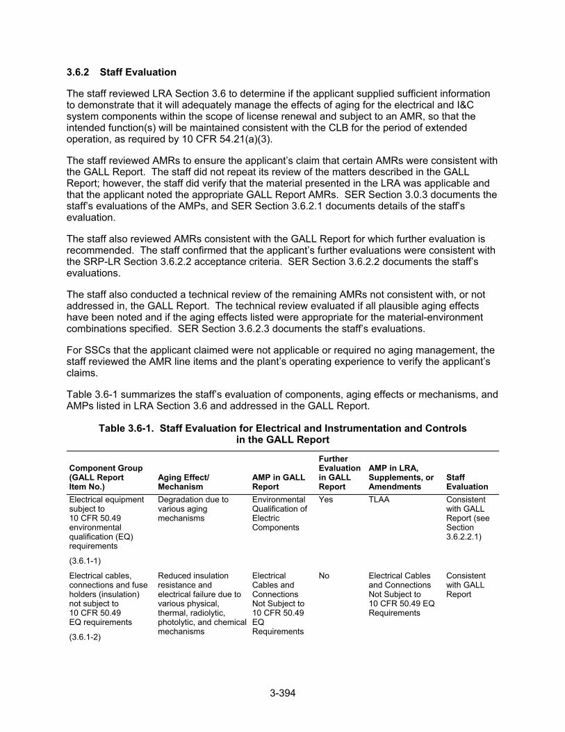
3-394
3.6.2 Staff Evaluation
The staff reviewed LRA Section 3.6 to determine if the applicant supplied sufficient information to demonstrate that it will adequately manage the effects of aging for the electrical and I&C system components within the scope of license renewal and subject to an AMR, so that the intended function(s) will be maintained consistent with the CLB for the period of extended operation, as required by 10 CFR 54.21(a)(3).
The staff reviewed AMRs to ensure the applicant’s claim that certain AMRs were consistent with the GALL Report. The staff did not repeat its review of the matters described in the GALL Report; however, the staff did verify that the material presented in the LRA was applicable and that the applicant noted the appropriate GALL Report AMRs. SER Section 3.0.3 documents the staff’s evaluations of the AMPs, and SER Section 3.6.2.1 documents details of the staff’s evaluation.
The staff also reviewed AMRs consistent with the GALL Report for which further evaluation is recommended. The staff confirmed that the applicant’s further evaluations were consistent with the SRP-LR Section 3.6.2.2 acceptance criteria. SER Section 3.6.2.2 documents the staff’s evaluations.
The staff also conducted a technical review of the remaining AMRs not consistent with, or not addressed in, the GALL Report. The technical review evaluated if all plausible aging effects have been noted and if the aging effects listed were appropriate for the material-environment combinations specified. SER Section 3.6.2.3 documents the staff’s evaluations.
For SSCs that the applicant claimed were not applicable or required no aging management, the staff reviewed the AMR line items and the plant’s operating experience to verify the applicant’s claims.
Table 3.6-1 summarizes the staff’s evaluation of components, aging effects or mechanisms, and AMPs listed in LRA Section 3.6 and addressed in the GALL Report.
Table 3.6-1. Staff Evaluation for Electrical and Instrumentation and Controls in the GALL Report
Component Group (GALL Report Item No.)
Aging Effect/ Mechanism
AMP in GALL Report
Further Evaluation in GALL Report
AMP in LRA, Supplements, or Amendments
Staff Evaluation
Electrical equipment subject to 10 CFR 50.49 environmental qualification (EQ) requirements
(3.6.1-1)
Degradation due to various aging mechanisms
Environmental Qualification of Electric Components
Yes TLAA Consistent with GALL Report (see Section 3.6.2.2.1)
Electrical cables, connections and fuse holders (insulation) not subject to 10 CFR 50.49 EQ requirements
(3.6.1-2)
Reduced insulation resistance and electrical failure due to various physical, thermal, radiolytic, photolytic, and chemical mechanisms
Electrical Cables and Connections Not Subject to 10 CFR 50.49 EQ Requirements
No Electrical Cables and Connections Not Subject to 10 CFR 50.49 EQ Requirements
Consistent with GALL Report
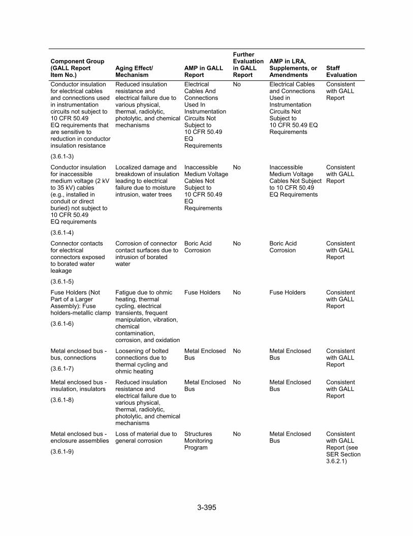
3-395
Component Group (GALL Report Item No.)
Aging Effect/ Mechanism
AMP in GALL Report
Further Evaluation in GALL Report
AMP in LRA, Supplements, or Amendments
Staff Evaluation
Conductor insulation for electrical cables and connections used in instrumentation circuits not subject to 10 CFR 50.49 EQ requirements that are sensitive to reduction in conductor insulation resistance
(3.6.1-3)
Reduced insulation resistance and electrical failure due to various physical, thermal, radiolytic, photolytic, and chemical mechanisms
Electrical Cables And Connections Used In Instrumentation Circuits Not Subject to 10 CFR 50.49 EQ Requirements
No Electrical Cables and Connections Used in Instrumentation Circuits Not Subject to 10 CFR 50.49 EQ Requirements
Consistent with GALL Report
Conductor insulation for inaccessible medium voltage (2 kV to 35 kV) cables (e.g., installed in conduit or direct buried) not subject to 10 CFR 50.49 EQ requirements
(3.6.1-4)
Localized damage and breakdown of insulation leading to electrical failure due to moisture intrusion, water trees
Inaccessible Medium Voltage Cables Not Subject to 10 CFR 50.49 EQ Requirements
No Inaccessible Medium Voltage Cables Not Subject to 10 CFR 50.49 EQ Requirements
Consistent with GALL Report
Connector contacts for electrical connectors exposed to borated water leakage
(3.6.1-5)
Corrosion of connector contact surfaces due to intrusion of borated water
Boric Acid Corrosion
No Boric Acid Corrosion
Consistent with GALL Report
Fuse Holders (Not Part of a Larger Assembly): Fuse holders-metallic clamp
(3.6.1-6)
Fatigue due to ohmic heating, thermal cycling, electrical transients, frequent manipulation, vibration, chemical contamination, corrosion, and oxidation
Fuse Holders No Fuse Holders Consistent with GALL Report
Metal enclosed bus - bus, connections
(3.6.1-7)
Loosening of bolted connections due to thermal cycling and ohmic heating
Metal Enclosed Bus
No Metal Enclosed Bus
Consistent with GALL Report
Metal enclosed bus - insulation, insulators
(3.6.1-8)
Reduced insulation resistance and electrical failure due to various physical, thermal, radiolytic, photolytic, and chemical mechanisms
Metal Enclosed Bus
No Metal Enclosed Bus
Consistent with GALL Report
Metal enclosed bus - enclosure assemblies
(3.6.1-9)
Loss of material due to general corrosion
Structures Monitoring Program
No Metal Enclosed Bus
Consistent with GALL Report (see SER Section 3.6.2.1)
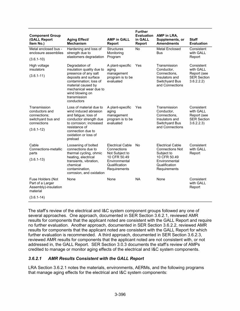
3-396
Component Group (GALL Report Item No.)
Aging Effect/ Mechanism
AMP in GALL Report
Further Evaluation in GALL Report
AMP in LRA, Supplements, or Amendments
Staff Evaluation
Metal enclosed bus - enclosure assemblies
(3.6.1-10)
Hardening and loss of strength due to elastomers degradation
Structures Monitoring Program
No Metal Enclosed Bus
Consistent with GALL Report
High voltage insulators
(3.6.1-11)
Degradation of insulation quality due to presence of any salt deposits and surface contamination; loss of material caused by mechanical wear due to wind blowing on transmission conductors
A plant-specific aging management program is to be evaluated
Yes Transmission Conductor, Connections, Insulators and Switchyard Bus and Connections
Consistent with GALL Report (see SER Section 3.6.2.2.2)
Transmission conductors and connections; switchyard bus and connections
(3.6.1-12)
Loss of material due to wind induced abrasion and fatigue; loss of conductor strength due to corrosion; increased resistance of connection due to oxidation or loss of preload
A plant-specific aging management program is to be evaluated
Yes Transmission Conductor, Connections, Insulators and Switchyard Bus and Connections
Consistent with GALL Report (see SER Section 3.6.2.2.3)
Cable Connections-metallic parts
(3.6.1-13)
Loosening of bolted connections due to thermal cycling, ohmic heating, electrical transients, vibration, chemical contamination, corrosion, and oxidation
Electrical Cable Connections Not Subject to 10 CFR 50.49 Environmental Qualification Requirements
No Electrical Cable Connections Not Subject to 10 CFR 50.49 Environmental Qualification Requirements
Consistent with GALL Report
Fuse Holders (Not Part of a Larger Assembly)-insulation material
(3.6.1-14)
None None NA None Consistent with GALL Report
The staff’s review of the electrical and I&C system component groups followed any one of several approaches. One approach, documented in SER Section 3.6.2.1, reviewed AMR results for components that the applicant noted are consistent with the GALL Report and require no further evaluation. Another approach, documented in SER Section 3.6.2.2, reviewed AMR results for components that the applicant noted are consistent with the GALL Report for which further evaluation is recommended. A third approach, documented in SER Section 3.6.2.3, reviewed AMR results for components that the applicant noted are not consistent with, or not addressed in, the GALL Report. SER Section 3.0.3 documents the staff’s review of AMPs credited to manage or monitor aging effects of the electrical and I&C system components.
3.6.2.1 AMR Results Consistent with the GALL Report
LRA Section 3.6.2.1 notes the materials, environments, AERMs, and the following programs that manage aging effects for the electrical and I&C system components:
3-397
Boric Acid Corrosion
Electrical Cable Connections Not Subject to 10 CFR 50.49 EQ Requirements
Electrical Cables and Connections Not Subject to 10 CFR 50.49 EQ Requirements
Electrical Cables and Connections Not Subject to 10 CFR 50.49 EQ Requirements Used in Instrumentation Circuits
Fire Protection
Fuse Holders
Inaccessible Medium Voltage Cables Not Subject to 10 CFR 50.49 EQ Requirements
Metal Enclosed Bus
Transmission Conductor, Connections, Insulators, and Switchyard Bus and Connections
LRA Table 3.6.2-1 summarizes AMRs for the electrical and I&C system components and notes AMRs claimed to be consistent with the GALL Report.
As discussed in SER Section 3.0.2.2.2, the applicant provided AMR results which cited generic notes A through J to indicate the AMR’s consistency with the GALL Report. The staff reviewed the information in the LRA for AMRs that the applicant claimed were consistent with the GALL Report (i.e., those AMR items the applicant cited generic notes A through E). The staff did not repeat its review of the matters described in the GALL Report; however, the staff did verify that the material presented in the LRA was applicable and that the applicant identified the appropriate GALL Report AMRs.
The staff reviewed the LRA to confirm that the applicant: (a) provided a brief description of the system, components, materials, and environments; (b) stated that the applicable aging effects were reviewed and evaluated in the GALL Report; and (c) identified those aging effects for the electrical and I&C systems components that are subject to an AMR. For those AMRs that the applicant claimed consistency, the staff compared the LRA AMRs to the corresponding GALL Report AMRs to verify the applicant’s claim of consistency. The staff’s evaluation follows.
3.6.2.1.1 Loss of Material Due to General Corrosion of Metal Enclosed Bus
LRA Table 3.6.1, item 3.6.1.09, states that the MEB Program will manage the effects of loss of material due to general corrosion. The staff noted that in Table 3.6.2 1, AMR results line that points to Table 3.6.1, item 3.6.1.09, the applicant cited generic note E.
The staff reviewed the AMR results line referenced to note E and determined that the component type, material, environment, and aging effects are consistent with the corresponding line of the GALL Report; however, where the GALL Report recommends GALL AMP XI.S6, “Structures Monitoring Program,” the applicant has proposed the MEB Program. As discussed in SER Section 3.0.3.2.15, the staff found that using visual inspections, as described in the MEB Program, is acceptable to inspect the outside of MEB enclosure assemblies for loss of material due to general corrosion.
3.6.2.1.2 Hardening and Loss of Strength Due to Elastomer Degradation of Metal Enclosed Bus
LRA Table 3.6.1, item 3.6.1.10, states that the MEB Program will manage the effects of hardening and loss of strength of elastomer due to elastomers degradation. The staff noted that
3-398
in the AMR results, the item from LRA Table 3.6.2-1 that points to LRA Table 3.6.1, item 3.6.1.10, the applicant cited generic note E.
The staff reviewed the AMR results line referenced to note E and determined that the component type, material, environment, and aging effect are consistent with the corresponding line of the GALL Report; however, where the GALL Report recommends GALL AMP XI.S6, “Structures Monitoring Program,” the applicant has proposed the MEB Program. As discussed in SER Section 3.0.3.2.15, the staff found visual inspection as described in the MEB Program acceptable to inspect the MEB elastomer degradation. The visual inspection is equivalent to that in the Structure Monitoring Program.
3.6.2.1.3 Conclusion
The staff evaluated the GALL Report AMR items that the applicant claimed were not applicable. On the basis of its review, the staff concludes that the AMR results which the applicant claimed were not applicable.
As discussed in SER Section 3.1.2.1, for those AMRs that the applicant claimed consistency with the GALL Report, the staff evaluated the applicant’s claim of consistency. The staff also reviewed information pertaining to the applicant’s consideration of recent operating experience and proposals for managing aging effects. On the basis of its review, the staff concludes that the AMR results, which the applicant claimed to be consistent with the GALL Report, are consistent.
Therefore, the staff concludes that the applicant has demonstrated that the effects of aging for these components will be adequately managed so that their intended function(s) will be maintained consistent with the CLB during the period of extended operation, as required by 10 CFR 54.21(a)(3).
3.6.2.2 AMR Results Consistent with the GALL Report for Which Further Evaluation Is Recommended
In LRA Section 3.6.2.2, the applicant further evaluates aging management, as recommended by the GALL Report, for the electrical and I&C system components and supplies information concerning how it will manage the following aging effects:
electrical equipment subject to EQ
degradation of insulator quality due to presence of any salt deposits and surface contamination, and loss of material due to mechanical wear
loss of material due to wind-induced abrasion and fatigue, loss of conductor strength due to corrosion, and increased resistance of connection due to oxidation or loss of preload
QA for aging management of nonsafety-related components
For component groups evaluated in the GALL Report, for which the applicant claimed consistency with the report and for which the report recommends further evaluation, the staff reviewed the applicant’s evaluation to determine if it adequately addressed the issues further evaluated. In addition, the staff reviewed the applicant’s further evaluations against the criteria contained in SRP-LR Section 3.6.2.2.The staff’s review of the applicant’s further evaluation follows.
3-399
3.6.2.2.1 Electrical Equipment Subject to Environmental Qualification
LRA Section 3.6.2.2.1 states that EQ is a TLAA, as defined in 10 CFR 54.3. Applicants must evaluate TLAAs in accordance with 10 CFR 54.21(c)(1). SER Section 4.4 documents the staff’s review of the applicant’s evaluation of this TLAA.
3.6.2.2.2 Degradation of Insulator Quality Due to Presence of Any Salt Deposits and Surface Contamination, and Loss of Material Due to Mechanical Wear
LRA Section 3.6.2.2.2 addresses degradation of insulator quality due to salt deposits and surface contamination and loss of material due to mechanical wear. The applicant stated that DCPP is a coastal plant, subject to frequent and persistent wind, which produces salt spray that can result in insulator contamination. The applicant also stated that it has observed instances of corrosion, resulting from the exposure of base metal on galvanized components. The DCPP plant-specific Transmission Conductor and Connections, Insulators, and Switchyard Bus and Connections AMP is an existing program that manages the aging effects of salt deposits on the in-scope, high-voltage insulators. The applicant stated that DCPP is located in an area with an average annual precipitation of 21 inches per year, where the outdoor environment is not subject to industry air pollution. The applicant also stated that minor contamination is washed away by rainfall, and cumulative buildup has not been experienced and is not expected to occur. Therefore, surface contamination caused by industrial pollution is not an applicable AERM for the period of extended operation.
Regarding mechanical wear, the applicant stated that industry experience has shown that transmission conductors are designed and installed not to swing significantly and cause insulator mechanical wear, due to wind blowing on the transmission conductors. The applicant also stated that the transmission lines, from the plant to the switchyard, traverse mountainous terrain, which exposes them to persistent and frequent high-wind conditions. The applicant also stated that DCPP transmission conductors are designed and installed to minimize swing, reducing insulator mechanical wear. The applicant further stated that, in the absence of a representative body of documented operating experience for similar operating environments to the contrary, DCPP will treat wind-induced mechanical wear as an AERM. The DCPP plant-specific Transmission Conductors, Connections, Insulators, and Switchyard Bus and Connections Program is an existing program that manages the aging effects of mechanical wear on the in-scope, high-voltage insulators.
The staff reviewed LRA Section 3.6.2.2.2 against SRP-LR Section 3.6.2.2.2, which states that degradation of insulator quality due to salt deposits or surface contamination may occur in high-voltage insulators. The GALL Report recommends further evaluation of plant-specific AMPs for plants at locations of potential salt deposits or surface contamination (e.g., in the vicinity of saltwater bodies or industrial pollution). Loss of material due to mechanical wear, caused by wind on transmission conductors, may occur in high-voltage insulators. The GALL Report recommends further evaluation of a plant-specific AMP to ensure that these aging effects are adequately managed.
The staff noted that, in general, various airborne materials, such as dust, salt and industrial effluents, can contaminate insulator surfaces. However, the buildup of surface contamination is gradual and, in most areas, such contamination is washed away by rain; the glazed insulator surface aids this contamination removal. Surface contamination can be a problem in areas where the greatest concentration of airborne particles, such as near facilities that discharge soot or near the sea coast where salt spray is prevalent. DCPP is a coastal plant, subject to frequent and persistent wind, which produces salt spray that can result in insulator contamination. The applicant proposed a plant-specific Transmission Conductors, Connections, Insulators, and
3-400
Switchyard Bus and Connections Program to manage the aging effect of surface contamination due to salt deposit. SER Section 3.0.3.3.2 documents the staff’s evaluation of this program. The staff determined that this AMP is acceptable because visual inspection is appropriate to inspect surface contamination for salt deposit.
The staff noted that mechanical wear is an aging effect for strain and suspension insulators in that they are subject to movement. Movement of the insulators can be caused by wind blowing the supported transmission conductor, causing it to swing from side to side. If this swinging is frequent enough, it could cause wear in the metal contact points to the insulator string and between an insulator and the supporting hardware. The transmission lines from the DCPP to the switchyard traverse mountainous terrain, which exposes them to persistent and frequent high-wind conditions. The applicant proposed a plant-specific Transmission Conductors, Connections, Insulators, and Switchyard Bus and Connections AMP to manage the aging effect of mechanical wear. SER Section 3.0.3.3.2 documents the staff’s evaluation of this program. The staff determined that this AMP is acceptable because visual inspection is appropriate to inspect for the aging effect of mechanical wear.
Based on the program noted above, the staff concludes that the applicant has met the SRP-LR Section 3.6.2.2.2 criteria. For those line items that apply to LRA Section 3.6.2.2.2, the staff determines that that the LRA is consistent with the GALL Report and that the applicant has demonstrated that it will adequately manage the effects of aging so that the intended function(s) will be maintained consistent with the CLB during the period of extended operation, as required by 10 CFR 54.21(a)(3).
3.6.2.2.3 Loss of Material Due to Wind Induced Abrasion and Fatigue, Loss of Conductor Strength Due to Corrosion, and Increased Resistance of Connection Due to Oxidation or Loss of PreLoad
LRA Section 3.6.2.2.3 addresses loss of material due to wind-induced abrasion and fatigue, loss of conductor strength due to corrosion, and increased resistance of connection due to oxidation or loss of preload. The applicant stated that industry experience has shown that transmission conductors are designed and installed to minimize mechanical wear due to wind induced abrasion and fatigue. The applicant also stated that the transmission lines, from the plant to the switchyard, traverse mountainous terrain that exposes them to persistent and frequent high-wind conditions. The DCPP transmission conductors are designed and installed to minimize swing-reducing conductor mechanical wear. The applicant stated that, in the absence of a representative body of documented operating experience for similar operating environments to the contrary, it will treat wind-induced mechanical wear as an AERM. The applicant proposed the existing plant-specific Transmission Conductors, Connections, Insulators, and Switchyard Bus and Connections Program to manage the aging effects of mechanical wear on the in-scope transmission conductors, switchyard bus, and connections.
The applicant stated that DCPP is located in a coastal environment, where salt sprays could cause corrosion of the transmission and switchyard bus conductors and increased resistance of connections. The applicant proposed the existing plant-specific Transmission Conductors, Connections, Insulators, and Switchyard Bus and Connections Program to manage the effects of increased resistance of connection due to oxidation, loss of preload, and mechanical wear.
The staff reviewed LRA Section 3.6.2.2.3 against the criteria in SRP-LR Section 3.6.2.2.3, which states that loss of material due to wind-induced abrasion and fatigue, loss of conductor strength due to corrosion, and increased resistance of connection due to oxidation or loss of preload could occur in transmission conductors and connections as well as in switchyard bus and
3-401
connections. The GALL Report recommends further evaluation of a plant-specific AMP to ensure that this aging effect is adequately managed.
The staff noted that transmission conductors do not normally swing significantly. When transmission conductors swing due to a substantial wind, they do not continue to swing for very long once the wind has subsided. Wind loading that can cause a transmission line to sway is considered in design and installation. Movement of the transmission conductors can be caused by wind blowing the supported transmission conductor, causing it to swing from side to side. If this swinging is frequent enough, it could cause wear in the metal contact points between an insulator and the transmission conductors. The transmission lines from the DCPP to the switchyard traverse mountainous terrain, which exposes them to persistent and frequent high-wind conditions. The applicant proposed a plant-specific Transmission Conductors, Connections, Insulators, and Switchyard Bus and Connections Program to manage the aging effect of mechanical wear. The staff evaluated this program in Section 3.0.3.3.2 of the SER. The staff determined that this AMP is acceptable because visual inspection is appropriate to inspect mechanical wear of transmission conductors.
The staff noted that, since DCPP is located in a coastal environment, salt could cause corrosion of the switchyard connections and increase resistance of connection. The applicant proposed a plant-specific AMP—Transmission Conductors, Connections, Insulators, and Switchyard bus and Connections Program—to manage the effects of connection due to oxidation. The staff evaluated this program in Section 3.0.3.3.2 of the SER. The staff determined that this AMP is acceptable because visual inspection and thermography are appropriate techniques to inspect and detect high resistance due to corrosion of switchyard connections.
Based on the program noted above, the staff concludes that the applicant has met the SRP-LR Section 3.6.2.2.3 criteria. For those line items that apply to LRA Section 3.6.2.2.3, the staff determines that that the LRA is consistent with the GALL Report and that the applicant has demonstrated that it will adequately manage the effects of aging so that the intended function(s) will be maintained consistent with the CLB during the period of extended operation, as required by 10 CFR 54.21(a)(3).
3.6.2.2.4 Quality Assurance for Aging Management of Nonsafety-Related Components
SER Section 3.0.4 documents the staff’s evaluation of the applicant’s QA program.
3.6.2.3 AMR Results Not Consistent with or Not Addressed in the GALL Report
In LRA Table 3.6.2-1, the staff reviewed additional details of the AMR results for material, environment, AERM, and AMP combinations not consistent with, or not addressed in, the GALL Report.
In LRA Table 3.6.2-1, via notes F through J, the applicant noted which combinations of component type, material, environment, and AERM do not correspond to a line item in the GALL Report. The applicant supplied further information about how it will manage the aging effects. Specifically, note F indicates that the material for the AMR line item component is not evaluated in the GALL Report. Note G indicates that the environment for the AMR line item component and material is not evaluated in the GALL Report. Note H indicates that the aging effect for the AMR line item component, material, and environment combination is not evaluated in the GALL Report. Note I indicates that the aging effect identified in the GALL Report for the line item component, material, and environment combination is not applicable. Note J indicates that neither the component nor the material and environment combination for the line item is evaluated in the GALL Report.
3-402
For component type, material, and environment combinations not evaluated in the GALL Report, the staff reviewed the applicant’s evaluation to determine if the applicant has demonstrated that it will adequately manage the effects of aging so that the intended function(s) will be maintained consistent with the CLB for the period of extended operation.
The staff reviewed LRA Table 3.6.2-1, which summarizes the results of AMR evaluations for the electrical and I&C component groups.
In LRA Table 3.6.2-1, the applicant stated that the copper-alloy lightning rods exposed to atmosphere or weather (external) are managed for loss of material by the Fire Protection Program. The AMR line items cite generic note J. The staff noted the following based on a Copper Development Institute article titled, “Resistance to Corrosion and Biofouling,” (Powell):
Copper alloys have a high resistance to pitting corrosion in seawater, an environment which is more corrosive than atmosphere or conditions.
Crevice corrosion seldom occurs in copper nickel-alloys.
Unless exposed to an ammonia environment, copper-nickel-alloys are resistant to SCC.
Dezincification (affects only the copper-alloy (greater than 15 percent zinc) components) occurs typically in stagnant water or seawater environments, both of which are more severe (because the component surfaces are not constantly exposed to liquid) than the atmospheric weather environment, even considering some salt content in the outside air given the station’s proximity to the ocean.
The staff also noted that, if sulfides are present in the atmosphere, a less adherent oxide film will form, which can lead to pitting or accelerated general corrosion. However, these aging effects would be detected by the periodic visual inspections under the Fire Protection Program. The staff reviewed the associated line items in the LRA and confirmed that the applicant has noted the correct aging effects for this component, material, and environmental combination because copper alloys are inherently general corrosion resistant because they form an adherent passive film and are resistant to other forms of corrosion when exposed to an outside weather environment. The staff noted that GALL Report, Table IX.C states that copper alloys (less than 15 percent zinc) are generally resistant to other aging effects, such as SCC, selective leaching, pitting, and crevice corrosion. SER Section 3.0.3.2.5 documents the staff’s evaluation of the applicant’s Fire Protection Program. The staff finds that the applicant’s proposal to manage aging using the Fire Protection Program is acceptable because the program uses periodic visual inspections that will detect loss of material.
Based on its review, the staff finds that the applicant has appropriately evaluated the AMR results of material, environment, AERM, and AMP combinations not evaluated in the GALL Report. The staff finds that the applicant has demonstrated that it will adequately manage the effects of aging so that the intended function(s) will be maintained consistent with the CLB for the period of extended operation, as required by 10 CFR 54.21(a)(3).
3.6.3 Conclusion
The staff concludes that the applicant has supplied sufficient information to demonstrate that it will adequately manage the effects of aging for the electrical and I&C system components within the scope of license renewal and subject to an AMR so that the intended function(s) will be maintained consistent with the CLB for the period of extended operation, as required by 10 CFR 54.21(a)(3).
3-403
3.7 Conclusion for Aging Management Review Results
The staff reviewed the information in LRA Section 3, “Aging Management Review Results,” and LRA Appendix B, “Aging Management Programs and Activities.” Based on its review of the AMR results and AMPs, the staff concludes, with the exception of Open Items 3.0.3.1.12-1, 3.0.3.2.8-1, 4.1-1, and 4.3-1 and Confirmatory Items 3.0.3.2.14-1 and 3.0.3.2.18-1, that the applicant has demonstrated that it will adequately manage the aging effects so that the intended function(s) will be maintained consistent with the CLB for the period of extended operation, as required by 10 CFR 54.21(a)(3). The staff also reviewed the applicable FSAR supplement program summaries and concludes, with the exception of open and confirmatory Items, that the supplement adequately describes the AMPs credited for managing aging, as required by 10 CFR 54.21(d).
With regard to these matters the staff concludes, with the exception of open and confirmatory items, that there is reasonable assurance that the applicant will continue to conduct the activities authorized by the renewed licenses in accordance with the CLB, and any changes made to the CLB, in order to comply with 10 CFR 54.21(a)(3), are in accordance with the Atomic Energy Act of 1954, as amended, and NRC regulations.

3-404
4-1
SECTION 4
4.0 TIME-LIMITED AGING ANALYSES
4.1 Identification of Time-Limited Aging Analyses
This section of the safety evaluation report (SER) addresses the identification of time-limited aging analyses (TLAAs). In license renewal application (LRA) Sections 4.2 through 4.8, Pacific Gas and Electric Company (PG&E or the applicant) addressed the TLAAs for Diablo Canyon Nuclear Power Plant (DCPP), Units 1 and 2. SER Sections 4.2 through 4.8 document the review of the TLAAs conducted by the staff of the U.S. Nuclear Regulatory Commission (NRC or the staff).
Certain plant-specific safety analyses involve time-limited assumptions, defined by the current operating term. Pursuant to Section 54.21(c)(1), of Title 10, Code of Federal Regulations (10 CFR 54.21(c)(1)), applicants must list those analyses in the current licensing basis (CLB) that meet the definition of a TLAA, as defined in 10 CFR 54.3.
In addition, under 10 CFR 54.21(c)(2), applicants must list plant-specific exemptions granted under 10 CFR 50.12, based on TLAAs. For any such exemptions, the applicant must evaluate and justify the continuation of the exemptions for the period of extended operation.
4.1.1 Summary of Technical Information in the Application
LRA Section 4.1 gives the basis for identifying those analyses that need to be evaluated as TLAAs in accordance with 10 CFR 54.21(c)(1). The applicant stated that, for the purpose of meeting this requirement, it evaluated those calculations that met the six criteria for defining an analysis as a TLAA, as specified in 10 CFR 54.3. The applicant gave its list of TLAAs, in LRA Table 4.1-1, that were noted as calculations that met the six criteria by searching the CLB. The applicant stated that it reviewed the list of common TLAAs in NUREG-1800, Revision 1, “Standard Review Plan for Review of License Renewal Applications for Nuclear Power Plants” (SRP-LR), dated September 2005. The applicant stated that its review of the CLB included a review of the following documents:
final safety analysis report (FSAR)
DCPP technical specifications (TS)
Inservice Inspection (ISI) and Electrical Equipment Environmental Qualification (EQ) Programs
NRC SERs and supplemental SERs for the original operating licenses
subsequent NRC safety evaluations (SEs)
PG&E and NRC docketed licensing correspondence
LRA Tables 4.1-1 and 4.1-2 identifies that the following analyses in the CLB meet the definition of a TLAA in 10 CFR 54.3:
Reactor Vessel Neutron Embrittlement Analyses
– Neutron Fluence Values
4-2
– Pressurized Thermal Shock
– Charpy Upper-Shelf Energy
– Pressure-Temperature (P-T) Limits
– Low Temperature Overpressure Protection
Metal Fatigue Analysis
– ASME Section III Class A Fatigue Analysis of Vessels, Piping, and Components
Reactor Pressure Vessel, Nozzles, and Studs
Reactor Vessel Closure Head and Associated Components
Reactor Coolant Pump Pressure Boundary Components
Pressurizer and Pressurizer Nozzles
Steam Generator (SG) ASME Section III Class 1, Class 2 Secondary Side, and Feedwater Nozzle Fatigue Analyses and Fatigue Qualifications Tests
Bulletin 88-11 Revised Fatigue Analysis of the Pressurizer Surge Line for Thermal Cycling and Stratification
TLAAs in Fatigue Crack Growth Assessments and Fracture Mechanics Stability Analyses for Leak-Before-Break (LBB) Elimination of Dynamic Effects of Primary Loop Piping Failures
– Fatigue Analyses for the Reactor Pressure Vessel Internals
– Effect of Reactor Coolant System environment on Fatigue Life of Piping and Components (Generic Safety Issue (GSI)-190)
– Assumed Thermal Cycle Count for Allowable Secondary Stress Range Reduction Factor in American National Standards Institute (ANSI) B31.1 Piping
– Fatigue Design and Analysis of Class IE Electrical Raceway Support Angle Fittings for Seismic Events
EQ of Electric Equipment
Containment Liner Plate, Metal Containment, and Penetration Fatigue Analysis
– Design Cycles for Containment Penetrations
Plant-Specific TLAAs
– Crane Load Cycle Limits
– TLAA Supporting Repair of Alloy 600 Materials
– Inservice Flaw Growth Analyses that Demonstrate Structural Stability for 40 Years
LRA Tables 4.1-1 and 4.1-2 identify that the following analyses in the CLB do not meet the definition of a TLAA in 10 CFR 54.3:
Metal Fatigue Analysis
– ASME Section III Class A Fatigue Analysis of Vessels, Piping, and Components
Reactor Coolant System Boundary Valves
4-3
Reactor Coolant Pressure Boundary Piping
Supplemental Fatigue Analysis TLAAs in Response to Bulletin 88-08 for Intermittent Thermal Cycles due to Thermal-Cycle-Driven Interface Valve Leaks and Similar Cyclic Phenomena
Thermal Embrittlement of Cast Austenitic Stainless Steel (CASS) Reactor Coolant Pumps
Cumulative Fatigue Usage Factor TLAA to Determine High Energy Line Break (HELB) Locations
– Flow-Induced Vibration Endurance Limit, Transient Cycle Count Assumptions, and Ductility Reduction of Fracture Toughness for the Reactor Vessel Internals
Concrete Containment Tendon Prestress Analysis
Containment Liner Plate, Metal Containment, and Penetration Fatigue Analysis
– Containment Concrete and Liner Plate
Plant-Specific Time-Limited Aging Analyses
– Reactor Vessel Underclad Cracking Analyses
– Reactor Coolant Pump Flywheel Fatigue Crack Growth Analysis
Pursuant to 10 CFR 54.21(c)(2), the applicant stated that it did not identify any exemptions granted under 10 CFR 50.12 based on a TLAA, as defined in 10 CFR 54.3.
4.1.2 Staff Evaluation
The staff reviewed the information to determine whether the applicant had provided sufficient information as required by 10 CFR 54.21(c)(1) and 10 CFR 54.21(c)(2). As defined by 10 CFR 54.3, TLAAs meet the following six criteria:
(1) involve systems, structures, and components within the scope of license renewal, as described in 10 CFR 54.4(a)
(2) consider the effects of aging
(3) involve time-limited assumptions defined by the current operating term
(4) are determined to be relevant by the applicant in making a safety determination
(5) involve conclusions, or provide the basis for conclusions, related to the capability of the system, structure, and component to perform its intended functions, as described in 10 CFR 54.4(b)
(6) are contained or incorporated by reference in the CLB
LRA Section 4.1 lists the TLAAs for the LRA. The staff reviewed the information to determine if the applicant has given sufficient information pursuant to 10 CFR 54.21(c)(1) and (2).
4.1.2.1 Evaluation of the Applicant’s Identification of TLAAs
The Statement of Considerations (SOC) on 10 CFR Part 54, as given in Federal Register Notice, Volume 60, Number 88, Section III.g.(i), (FRN Volume 60, No. 88, dated May 8, 1995), clarifies when an analysis in the CLB needs to be identified as a TLAA in accordance with the rule's TLAA identification criteria. SRP-LR Section 4.1 gives additional guidance as to when an analysis in the CLB needs to identified as a TLAA in accordance with 10 CFR 54.3.
4-4
For each of the TLAAs identified in LRA Table 4.1-1, the staff evaluated the applicant's basis for disposition of these TLAAs, in accordance with 10 CFR 54.21(c)(1)(i), 10 CFR 54.21(c)(1)(ii), or 10 CFR 54.21(c)(1)(iii), is discussed in SER Sections 4.3, 4.4, 4.5, 4.6, or 4.7.
For those CLB analyses listed in LRA Table 4.1-1 and 4.1-2 noted as not meeting the definition of a TLAA, the staff reviewed the applicant's basis, or bases, for claiming the analysis was not a TLAA against the six criteria for determining a TLAA in 10 CFR 54.3.
4.1.2.2 Evaluation of the Applicant’s Identification of those Exemptions in the CLB that are Based on TLAAs
As required by 10 CFR 54.21(c)(2), the applicant must list all exemptions granted under 10 CFR 50.12, that are based on TLAAs, and provide an evaluation that justifies the continuation of these exemptions for the period of extended operation. In LRA Section 4.8, the applicant stated that the CLB included a total of 15 exemptions that were granted in accordance with exemption request acceptance provisions of 10 CFR 50.12 and that, of these, the exemption to use an LBB evaluation of reactor coolant system piping for Units 1 and 2 was the only exemption based on a TLAA. SER Section 4.8 documents the staff’s evaluation of this exemption.
The staff reviewed the following types of documents to verify if there were any additional exemptions in the CLB that, granted in accordance with the exemption criteria of 10 CFR 50.12, based on a TLAA:
DCPP, Unit 1 Operating License No. DPR-80
DCPP, Unit 2 Operating License No. DRP-82
Applicable exemptions to the requirements in 10 CFR 50.60(b) related to neutron irradiation embrittlement analyses granted under the requirements in 10 CFR 50.12.
LRA Section 4.8 gives the applicant’s list of exemptions that need to be identified in accordance with10 CFR 54.21(c)(2). The applicant identified LBB as the only exemption that was granted based on a TLAA.
The staff noted that, in an NRC letter dated May 3, 1999, the staff issued PG&E an exemption under 10 CFR 50.12 to apply ASME Code Case N-514 as the basis for establishing the low temperature over-pressurization protection (LTOP) system pressure lift and arming temperature set points for the credited power operated relief valves (PORVs). The staff noted that the exemption granted PG&E permission to set the LTOP system pressure lift set points for the PORVs up to 110 percent of the limiting pressure established in the approved P-T limits curve for the system’s temperature enable set point. The staff noted that the exemption also permitted the applicant to set the arming temperature for the LTOP system in accordance with the Code Case N-514 arming temperature set point methodology.
The staff noted that the LTOP system set points and P-T limits are currently updated according to NRC-approved P-T Limits Report (PTLR—the current version is PTLR-1, Revision 10). In LRA Section 4.2.3, the applicant noted that the P-T limits for Units 1 and 2 are TLAAs. Thus, the staff determined that the granting of this exemption and the establishment of the LTOP system pressure set point was a function of the limiting pressure value established in the P-T limit curves for the LTOP system’s enable temperature. The staff noted that, if this exemption remained in effect for the CLB, the exemption may need to be identified as an exemption for the LRA that meets the requirements in 10 CFR 54.21(c)(2) because granting the exemption under
4-5
10 CFR 50.12 was based on a value in the approved P-T limits and the P-T limits for Unit 1 and Unit 2 have been identified as TLAAs.
By letter dated September 23, 2010, the staff issued RAI 4.1-5, requesting that the applicant clarify if the granted exemption on the use of Code Case N-514 remained in effect for the CLB and to justify not identifying this as an exemption based on a TLAA in accordance with the criterion in 10 CFR 54.21(c)(2).
In its response dated October 21, 2010, the applicant amended LRA Sections 4.1.2 and 4.8 to identify the exemption on use of ASME Code Case N-514 to establish the LTOP system setpoints for Units 1 and 2 as an additional exemption based on a TLAA. The applicant stated that the application of ASME Code Case N-514 is described in LRA Section 4.2.4, which discusses the P-T limits TLAA. The staff's evaluation for this exemption and its relationship to the applicant’s P-T limits TLAA and bases for updating these P-T limits and LTOP system setpoints under the applicant’s PTLR update process in SER Section 4.2.4. Based on its review, the staff finds that the applicant has resolved RAI 4.1-5 because the applicant has amended the LRA to identify the exemption on use of ASME Code Case N-514 as an applicable exemption based on a TLAA consistent with the requirements of 10 CFR 54.21(c)(2). The staff evaluates this exemption in SER Section 4.8 and the relationship of this exemption to the applicant’s P-T limits TLAA in SER Section 4.2.4.
4.1.3 Conclusion
On the basis of its review, the staff finds that the applicant has provided an acceptable list of TLAAs, as required by 10 CFR 54.21(c)(1), and that two exemptions have been granted on the basis of a TLAA for which continuation has been justified during the period of extended operation as required by 10 CFR 54.21(c)(2).
4.2 Reactor Vessel Neutron Embrittlement
Neutron embrittlement is the term for changes in mechanical properties of reactor pressure vessel (RPV) materials caused by exposure to a fast neutron flux, energy values greater than 1 megaelectron-volt (E greater than 1 MeV), within the vicinity of the reactor core, called the beltline region. The most pronounced material change is a reduction in fracture toughness. As fracture toughness decreases with cumulative fast neutron exposure, the material’s resistance to cleavage and ductile fracture decreases. Fracture toughness also depends on temperature. The reference temperature (RTNDT), above which the material behaves in a ductile manner and below which the material behaves in a brittle manner, increases as the fluence increases and requires higher temperatures for continued ductility. Under 10 CFR 50.60, all light-water reactors must meet the fracture toughness, P-T limits, and material surveillance program requirements for the reactor coolant pressure boundary in Appendices G and H of 10 CFR Part 50. The RTNDT value, which is evaluated at one quarter or three quarters of the RPV wall thickness (1/4T or 3/4T) for a specified effective full power years (EFPYs) is usually referred to as the adjusted reference temperature (ART) in the P-T limit applications. The fracture toughness requirements for protecting the RPV of a pressurized water reactor (PWR) against the consequences due to a pressurized thermal shock (PTS) event (a severe overcooling event concurrent with or followed by significant pressure in the RPV) are provided in 10 CFR 50.61. Neutron fluence, upper shelf energy (USE), PTS, and P-T limits are time-dependent items that must be investigated to evaluate RPV embrittlement or reduction of fracture toughness. The CLB analyses evaluating reduction of fracture toughness of the RPV for 40 years are TLAAs. The following sections address neutron fluence, USE, PTS, P-T limits for RPV beltline materials for the period of extended operation.
4-6
4.2.1 Reactor Vessel Fluence
4.2.1.1 Summary of Technical Information in the Application
LRA Section 4.2.1 summarizes the evaluation of reactor vessel (RV) fluence for the period of extended operation, projecting neutron exposure levels for the reactor pressure vessels for an operating period extending to 54 EFPYs.
LRA Section 4.2.1 summarizes the RV neutron fluence determination, which the applicant performed to support the neutron embrittlement analyses. The applicant described recent fluence calculations and comparisons to unit-specific, in-vessel dosimetry evaluations.
The applicant stated that the fluence calculations for both units adhere to NRC Regulatory Guide (RG) 1.190 and were projected to a 54 EFPY exposure, which represents the end of license extended (EOLE) period. The applicant also stated that Unit 1 calculations account for an uprate from 3,338 MWt to 3,411 MWt at the end of Cycle 11. The applicant assumed that the spatial core power distributions of future cycles are characterized by an average of recent operating cycles.
The applicant referenced the following surveillance reports, which further characterize the EOLE fluence calculations:
For Unit 1, WCAP-15958, “Analysis of Capsule V from Pacific Gas and Electric Company Diablo Canyon Unit 1 Reactor Vessel Radiation Surveillance Program”
For Unit 2, WCAP-15423, “Analysis of Capsule V from Pacific Gas and Electric Company Diablo Canyon Unit 2 Reactor Vessel Radiation Surveillance Program”
The LRA identifies a disposition of this TLAA in accordance with 10 CFR 54.21(c)(1)(ii), that the neutron fluence analyses have been projected to the end of the period of extended operation. The LRA states that the validity of the neutron fluence calculations, and the analyses that depend on them, will be managed in accordance with the Reactor Vessel Surveillance Program, described in LRA Section B2.1.15, and in accordance with 10 CFR 54.21(c)(1)(iii).
4.2.1.2 Staff Evaluation
The staff reviewed LRA Section 4.2.1 to verify, pursuant to 10 CFR 54.21(c)(1)(ii), that the neutron fluence analyses have been projected to the end of the period of extended operation. In addition, the staff reviewed this section to verify, pursuant to 10 CFR 54.21(c)(1)(iii), that the effects of aging on the intended functions will be adequately managed for the period of extended operation.
RG 1.190 describes acceptable ways to calculate RV neutron fluence and states that fluence calculations should adhere to NRC-approved methodology. It also supplies acceptable qualification criteria for neutron fluence calculations.
The surveillance reports, cited in the LRA, supply additional information describing the DCPP fluence calculations. These calculations were performed consistent with WCAP-14040-A, “Methodology Used to Develop Cold Overpressure Mitigating System Setpoints and RCS Heatup and Cooldown Limit Curves,” which the staff approved, having found that the methodology describes an acceptable technique for performing fluence calculations. The surveillance reports for both units state that forward transport calculations were performed using a three-dimensional flux synthesis and P-5 Legendre expansion. The core and vessel geometry were represented with S16 angular quadrature. Nuclear data was obtained from the BUGLE-96
4-7
wide-group cross section library, which is based on ENDF/B-VI nuclear data. These aspects of the fluence calculation meet or exceed the guidance set forth in RG 1.190. Because the fluence calculations were performed using an NRC-approved methodology that adheres to RG 1.190 guidance, the staff finds the DCPP fluence determination for EOLE acceptable.
The capsule dosimetry reports describe qualification of the fluence calculations using DCPP unit-specific capsule dosimetry. In both cases, the measured-to-calculated values for reaction rates agree within the RG 1.190-stipulated value of ± 20 percent. The fluence calculation methodology is also qualified against benchmarks described in RG 1.190; this qualification is generic and is described in WCAP-14040-A. Because the applicant referenced generic qualification and gave plant-specific validation data, the staff finds that the fluence calculations adhere to RG 1.190 validation recommendations and are, therefore, acceptably qualified.
The applicant stated that fluence values used in the RV neutron embrittlement analyses are projected to 54 EFPYs, reflect actual operating history, and include projected neutron fluxes based on recent operations. The staff finds that these assumptions are acceptable because they result in a fluence prediction that is bounding for the 60-year renewed license and account for past, present, and planned facility operation.
The applicant stated that it will manage the validity of the neutron fluence calculations, and the analyses that depend on them, in accordance with the Reactor Vessel Surveillance Program, described in LRA Section B2.1.15, and in accordance with 10 CFR 54.21(c)(1)(iii). The staff finds this acceptable because the Reactor Vessel Surveillance Program will provide assurance that the neutron fluence calculations remain consistent with future facility operation.
The staff finds the applicant’s fluence calculations acceptable to support the period of extended operation for DCPP. The staff’s finding is based on the following considerations:
The fluence calculations are performed using acceptably qualified, NRC-approved methods in accordance with RG 1.190.
The fluence calculations account acceptably for past, present, and planned facility operation.
4.2.1.3 FSAR Supplement
The applicant provided an FSAR supplement summary description of its TLAA evaluation of RV neutron fluence in LRA Section A3.1.1. Based on its review of the FSAR supplement, the staff concludes that the summary description of the applicant’s actions to address RV neutron fluence is adequate.
4.2.1.4 Conclusion
On the basis of its review, the staff concludes that the applicant has demonstrated, pursuant to 10 CFR 54.21(c)(1)(ii), that for RV neutron fluence, the analyses have been projected to the end of the period of extended operation, and pursuant to 10 CFR 54.21(c)(1)(iii), that the effects of aging will be adequately managed during the period of extended operation. The staff also concludes that the FSAR supplement contains an appropriate summary description of the TLAA evaluation, as required by 10 CFR 54.21(d).
4-8
4.2.2 Pressurized Thermal Shock
4.2.2.1 Summary of Technical Information in the Application
LRA Section 4.2.2 summarizes the PTS evaluation of the Unit 1 and 2 RV beltline materials for the period of extended operation against the screening criteria established in accordance with 10 CFR 50.61, “Fracture Toughness Requirements for Protection Against Pressurized Thermal Shock Events.” The screening criteria are 270 °F for plates, forging, and axial weld materials and 300 °F for circumferential weld materials.
For Unit 1, one weld material was projected to exceed the PTS screening criteria. The applicant stated that it expects to implement 10 CFR 50.61a, “Alternate Fracture Toughness Requirements for Protection Against Pressurized Thermal Shock Events,” at least three years prior to exceeding the PTS screening criteria of 10 CFR 50.61. The applicant further stated that it expects the weld material to comply with the criteria in 10 CFR 50.61a through the end of the period of extended operation. Therefore, the applicant concluded that the effects of aging on PTS evaluations will be adequately managed to the end of the period of extended operation in accordance with 10 CFR 54.21(c)(1)(iii).
For Unit 2, the applicant projected the pressurized thermal shock reference temperature (RTPTS) values for all beltline and extended beltline materials to the end of the period of extended operation. The applicant’s projections show that the RTPTS values remain below the screening criteria for the period of extended operation. Therefore, the applicant dispositioned the PTS TLAA as being projected to the end of the period of extended operation in accordance with 10 CFR 54.21(c)(1)(ii).
4.2.2.2 Staff Evaluation
The staff reviewed LRA Section 4.2.2 to verify, pursuant to 10 CFR 54.21(c)(1)(iii), that the effects of aging on the PTS analyses for Unit 1 will be adequately managed for the period of extended operation, and, pursuant to 10 CFR 54.21(c)(1)(ii), that the PTS analyses for Unit 2 have been projected for the period of extended operation.
The fracture toughness requirements protecting the PWR RVs against the consequences of PTS are found in 10 CFR 50.61. Applicants are required to assess the RV materials’ projected RTPTS values through the end of their operating license. The rule requires each applicant to calculate the end of life (EOL) RTPTS value for each RPV beltline material. The RTPTS value for each beltline material is the sum of the unirradiated reference temperature (RTNDT(u)), a shift in the RTNDT value caused by neutron irradiation of the material (ΔRTNDT), and a margin value to account for uncertainties (M). Screening criteria, against which the calculated values are to be evaluated, are also given in the PTS Rule.
As stated in LRA Section 4.2.2.1, the screening criteria are 270 °F for plates, forgings, and axial weld materials and 300 °F for circumferential weld materials. 10 CFR 50.61 provides a discussion regarding the calculations of ΔRTNDT and the M value. In 10 CFR 50.61, ΔRTNDT is the product of a chemistry factor and a fluence factor, where the fluence factor is dependent upon the neutron fluence at the clad-to-base metal interface, and the chemistry factor is dependent upon information from either the surveillance material or from the tables in 10 CFR 50.61. If the RV beltline material is not represented by surveillance material, its chemistry factor may be determined using the tables and the methodology documented in 10 CFR 50.61. The chemistry factor determined from the tables in 10 CFR 50.61 depends upon the amount of copper (Cu) and nickel (Ni) in the material. If the RV beltline material is represented by surveillance material, its chemistry factor may be determined from the
4-9
surveillance data using the methodology documented in 10 CFR 50.61. The methods of determining RTPTS values in 10 CFR 50.61 are equivalent to the methods of determining RTNDT values in RG 1.99, Revision 2.
LRA Tables 4.2-4 and 4.2-5 provide the data and results for the PTS evaluation of all the beltline and extended beltline materials for Units 1 and 2. The tables provide, for each RV material, the location, heat number, material specification, Cu and Ni content, chemistry factors, initial RTNDT, EOLE neutron fluence, fluence factor, ΔRTPTS, margin term, and the projected RTPTS at the end of the period of extended operation. The staff performed a confirmatory calculation of the chemistry factor, fluence factor, ΔRTPTS, margin, and RTPTS. The chemistry factors were checked using Tables 1 and 2 of 10 CFR 50.61, interpolating where necessary. The fluence factor, ΔRTPTS, margin, and RTPTS were calculated using the equations of 10 CFR 50.61, unless credible surveillance data were available.
Credible surveillance data were available only for one Unit 2 material, intermediate shell plate B5454-1. For this material, the staff verified the chemistry factor from the applicant’s source reference and calculated the RTPTS value for plate B5454-1, using both the method based on the surveillance data and the method based on the Table 2 of 10 CFR 50.61. The RTPTS value calculated, using Table 2 of 10 CFR 50.61, is 210 °F versus the RTPTS value of 190 °F calculated using the surveillance data. Intermediate shell plate B5454-3 (heat no. C5168-2) actually has a higher RTPTS value of 223.2 °F, so it is the controlling plate material for Unit 2. No surveillance data are available for this plate, so Table 2 of 10 CFR 50.61 was used to calculate the RTPTS value.
As part of its independent evaluation of the RTPTS values, the staff checked the Cu, Ni, and initial (unirradiated) RTNDT values for each beltline material against the corresponding values from the Reactor Vessel Integrity Database (RVID) for each beltline material. Some of the material locations included by the applicant in the LRA are extended beltline materials (i.e., those that will reach a neutron fluence of 1x10¹⁷ n/cm2 (E greater than 1 MeV) during the period of extended operation) and, therefore, do not have any data in the RVID. For Unit 1, the RTPTS values provided by the applicant in the LRA are in agreement with the RTPTS values in the RVID. The applicant provided lower Cu values for intermediate shell plates B4106-1 (heat no. C2884-1), B4106-2 (heat no. C2854-2), and B4106-3 (heat no. C2793-1), and lower Ni values for plate B4106-3 and B4107-3 (heat no. C3131-1) than the corresponding Cu and Ni values in the RVID for these plates. The Cu and Ni values provided in the LRA for plate B4106-3 match the best estimate values provided in the most recent surveillance capsule report for Unit 1. By letter dated July 20, 2010, the staff issued RAI 4.2-1, and requested that the applicant supply the source reference for the Cu and Ni content for Intermediate Shell Plates B4106-1, B4106-2, and B4107-3.
In its August 17, 2010, response, the applicant stated that the Cu and Ni values provided in LRA Tables 4.2-4 and 4.2-6 are from FSAR, Table 5.2-17A. The applicant further stated that the source reference for the FSAR values is WCAP-13771, “Evaluation of Pressurized Thermal Shock for Diablo Canyon Unit 1,” (Chicots, 1993). Finally, the applicant stated that the Cu and Ni values presented in this WCAP, for the materials in question, were averaged from material test certifications for the original fabrication. The staff finds the Cu and Ni values acceptable since the values are from a later source reference than the reference for the Cu values in the RVID and have been determined consistent with the requirement of 10 CFR 50.61, which states that the best estimate will normally be the mean of the measured values for a plate or forging. The staff also notes that the EOLE RTPTS values are acceptable for either set of Cu and Ni values. Therefore, the staff’s concern described in RAI 4.2.2-1 is resolved.
4-10
For Unit 2, the RVID listed the Cu content of intermediate shell plate B5454-1 (heat no. C5161-1) as 0.15 weight percent, versus the value provided in the LRA for this plate of 0.14 weight percent. The most recent surveillance capsule report for Unit 2 listed the best estimate Cu content as 0.14 weight percent, consistent with the LRA. For intermediate-to-lower shell weld 9-201 (heat no. 10120), the applicant provided a Cu content of 0.046 weight percent and Ni content of 0.082 weight percent, versus the RVID values of 0.04 weight percent and 0.030 weight percent. The initial (unirradiated) RTNDT values given by the applicant in the LRA for weld 9-201 are identical to the values in the RVID for the corresponding materials. The staff verified that the Cu content provided by the applicant for weld 9-201 is consistent with the values reported in Combustion Engineering Owner’s Group (CEOG) Report CE-NPSD-1039, Revision 2, “Best Estimate Cu and Ni Values in CE Fabricated Reactor Vessel Welds.” Since the applicant’s values of Cu and Ni for intermediate-to-lower shell weld 9-201 are higher and, therefore, more conservative with regard to PTS and represent the best estimate values for this material heat, the staff finds the applicant’s Cu and Ni values acceptable.
For the determination of the RTPTS values for Unit 1 and most of the Unit 2 materials, the applicant stated—in LRA Section 4.2.2—that it used RG 1.99, Revision 2, Position 1.1, which defines the margin term as:
M=2(σI2 + σΔ
2)1/2
Where σI is the standard deviation for the initial RTNDT and σΔ is the standard deviation for ΔRTNDT. RG 1.99, Revision 2, Position 1.1 states that σI is to be estimated from the precision of the test method, if a measured value of initial RTNDT for the material in question is available. If a measured value of initial RTNDT is not available, and generic mean values for that class of material are used, σI is the standard deviation obtained from the set of data used to establish the mean.
RG 1.99, Revision 2, Position 1.1, also states that the standard deviation for ΔRTNDT, σΔ, is 28 °F for welds and 17 °F for base metal, except that σΔ need not exceed 0.50 times the mean value of ΔRTNDT (Note: 10 CFR 50.61 requires the margin to be determined in the same manner as RG 1.99 but uses the term σu rather than σI for the standard deviation of the unirradiated RTNDT).
The staff performed preliminary confirmatory calculations of RTPTS using the σΔ term as defined in RG 1.99, Revision 2. To obtain the margin term for some of the materials listed in LRA Table 4.2-4, it appeared that the applicant used a value of 17 °F for σI, while a value of 0 °F was used for other materials. Therefore, by letter dated July 20, 2010, the staff issued RAI 4.2.2-2 and asked that the applicant give the basis for the σI values used to calculate the margin terms for the Units 1 and 2 RTPTS calculations.
In its August 17, 2010, response, the applicant confirmed that a σI value of 17 °F was used for those materials for which a generic unirradiated RTNDT (RTNDT(u)) was used, specifically welds made with Linde 0091, 1092, and 124, and ARCOS B-5 weld fluxes. A σI value of 17 °F was also used for materials for which RTNDT(u) was determined using branch technical position (BTP) MTEB 5.2.1.1(3)(b) (currently NUREG-0800 BTP 5-3, Sections B1.1(3) and B1.1(4)), which allows RTNDT(u) to be estimated from tests of Charpy V-Notch (CV) specimens. For the plates, the σI term of 17 °F was used even though a non-generic RTNDT(u) was obtained using BTP MTEB 5.2.1.1(3)(b). The staff finds the applicant’s response to RAI 4.2.2-2 acceptable because use of a σI term of 17 °F for materials, for which a generic RTNDT(u) was used, is consistent with the requirements of 10 CFR 50.61. In addition, use of a σI term of 17 °F, for materials for which RTNDT(u) was obtained using BTP MTEB 5.2.1.1(3)(b), is conservative. Therefore, the staff’s concern described in RAI 4.2.2-2 is resolved.
4-11
The staff’s calculated RTPTS values were identical to the applicant’s values. For certain materials, the staff used 17 °F for σI as discussed above.
For Unit 1, one material and location exceeds the PTS screening criteria. Lower shell longitudinal weld 3-442C has a projected RTPTS value at EOLE of 280.4 °F, which the staff’s calculation confirmed. As a result, the applicant stated in LRA Section 4.2.2 that it will implement 10 CFR 50.61a, “Alternate Fracture Toughness Requirements for Protection Against Pressurized Thermal Shock Events,” at least three years prior to exceeding the PTS screening criteria of 10 CFR 50.61. The applicant further stated that it expects the weld material to comply with the criteria in 10 CFR 50.61a through the end of the period of extended operation. Therefore, the applicant concluded, with respect to PTS, that it will adequately manage the effects of aging to the end of the period of extended operation in accordance with 10 CFR 54.21(c)(1)(iii).
The applicant also stated that it would implement alternate options, such as flux reduction, as provided in 10 CFR 50.61, if the provisions of 10 CFR 50.61 cannot be met. In addition, the applicant stated that it would continue to monitor the Unit 1 RV fluence via the Reactor Vessel Surveillance Program. Although not explicitly mentioned in the SRP-LR, as an option for aging management of PTS (since 10 CFR 50.61a was approved subsequent to issuance of the SRP-LR), implementation of 10 CFR 50.61a meets the intent of 10 CFR 54.21(c)(1)(iii). For license renewal applicants that disposition the PTS TLAA as being adequately managed for the period of extended operation in accordance with 10 CFR 54.21(c)(1)(iii), the SRP-LR recommends, in part, that the applicant provide the projected date and fluence values at which the limiting material will exceed the screening criteria in 10 CFR 50.61.
In LRA Section 4.2.2, the applicant stated that lower shell longitudinal weld 3-442C will satisfy the PTS screening criteria until approximately 43 EFPY. Based on this information, along with the EOLE EFPY fluence value at 54 EFPYs of 2.04x10¹⁹ n/cm2 (E > 1 MeV), given in LRA Table 4.2-4, the staff estimates the screening criteria will be reached approximately in the year 2032 at a fluence of 1.62x10¹⁹ n/cm2 (E > 1 MeV). Therefore, since the applicant supplied the estimated EFPY value at which the PTS screening criterion will be exceeded, the staff finds that the applicant has met the intent of the recommendations of the SRP-LR, with respect to dispositioning the PTS TLAA as being adequately managed in accordance with 10 CFR 54.21(c)(1)(iii).
The staff finds that for Unit 1, the applicant will adequately manage the effects of neutron embrittlement for the period of extended operation in accordance with 10 CFR 54.21(c)(1)(iii). This finding is based on the fact that the applicant is monitoring reactor pressure vessel fluence via the Reactor Vessel Surveillance Program and because the applicant has proposed to use 10 CFR 50.61a as an alternative means to demonstrate adequate fracture toughness of the RV.
For Unit 2, the staff finds that the RTPTS values have been projected to the end of the period of extended operation in accordance with 10 CFR 54.21(c)(1)(ii), based on its review of the input data and confirmatory calculations of the RTPTS values.
4.2.2.3 FSAR Supplement
The applicant provided an FSAR supplement summary description of its TLAA evaluation of PTS in LRA Section A.3.1.2. Based on its review of the FSAR supplement, the staff concludes that the summary description of the applicant’s actions to address PTS is adequate.
4-12
4.2.2.4 Conclusion
On the basis of its review, the staff concludes that the effects of aging on the PTS analyses for Unit 1 will be adequately managed for the period of extended operation in accordance with 10 CFR 54.21(c)(1)(iii). On the basis of its review, the staff concludes that the PTS analyses for Unit 2 have been projected for the period of extended operation in accordance with 10 CFR 54.21(c)(1)(ii). The staff also concludes that the FSAR supplement contains an appropriate summary description of the TLAA evaluation, as required by 10 CFR 54.21(d).
4.2.3 Charpy Upper Shelf Energy
4.2.3.1 Summary of Technical Information in the Application
LRA Section 4.2.3 summarizes the evaluation of USE values for the period of extended operation.
The applicant stated that, in accordance with RG 1.99, Revision 2, the CV USE data from Unit 1, surveillance capsule V, were determined not to be credible and were, therefore, not included in the EOLE CV USE projections. The applicant stated that the CV USE values were projected to 54 EFPYs of operation using RG 1.99, Revision 2, Position 1.2. LRA Table 4.2-6 supplies the EOLE CV USE values for the Unit 1 beltline and extended beltline materials. The limiting value was 58.5 ft-lb for lower shell longitudinal weld 3442C.
For Unit 2, the applicant stated that, in accordance with RG 1.99, Revision 2, the CV USE data from Unit 2, surveillance capsule V, were deemed credible for Intermediate Shell Plate B5454-1. The applicant stated that the CV USE values were projected to 54 EFPYs of operation using RG 1.99, Revision 2, Position 1.2. LRA Table 4.2-7 supplies the EOLE CV USE values for the Unit 2 beltline and extended beltline materials. The limiting value was 53.7 ft-lb for lower shell longitudinal weld 3-201C.
In Tables 4.2-6 and 4.2-7, the applicant provided the inputs and results of the USE evaluation for Units 1 and 2, respectively. The tables give, for each beltline material, the material location, heat number, material type (specification), Cu content, EOLE fluence, unirradiated (initial) USE, percent drop in USE, and projected USE at EOLE. The fluence provided was the 1/4T fluence, consistent with the requirements of Appendix G to 10 CFR Part 50.
The applicant stated that the CV USE values were dispositioned in accordance with 10 CFR 54.21(c)(1)(ii), and the re-evaluations demonstrated that the CV USE in the limiting material of each unit will remain above the 10 CFR Part 50, Appendix G acceptance criterion of 50 ft-lb for the period of extended operation.
4.2.3.2 Staff Evaluation
The staff reviewed LRA Section 4.2.3 to verify, pursuant to 10 CFR 54.21(c)(1)(ii), that the analyses have been projected to the end of the period of extended operation.
Appendix G of 10 CFR Part 50 requires the initial USE value be no less than 75 ft-lb in the unirradiated condition and no less than 50 ft-lb in the fully irradiated condition throughout the licensed life of the plant for each reactor vessel beltline material unless it is demonstrated in a manner approved by the Director, Office of Nuclear Reactor Regulation or Director, Office of New Reactors, as appropriate, that lower values of Charpy upper-shelf energy will provide margins of safety against fracture equivalent to those required by Appendix G of Section XI of the ASME Code.