Embed Size (px)
Citation preview
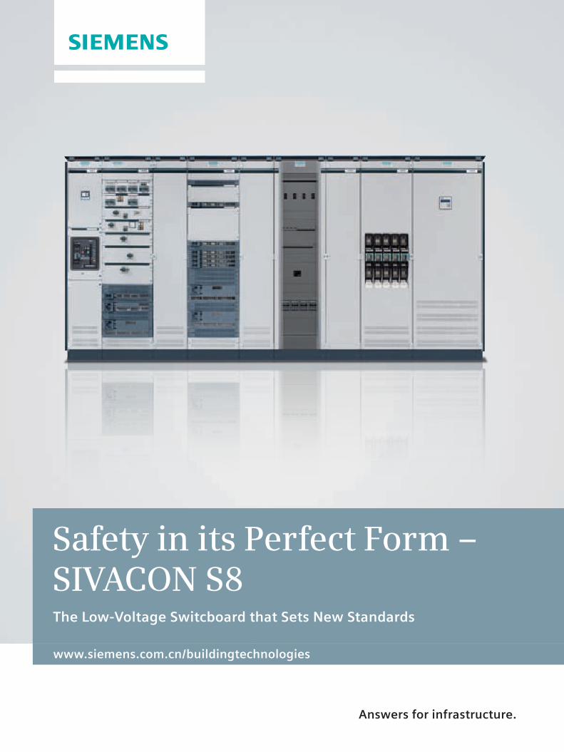
www.siemens.com.cn/buildingtechnologies
Safety in its Perfect Form – SIVACON S8The Low-Voltage Switcboard that Sets New Standards
Answers for infrastructure.
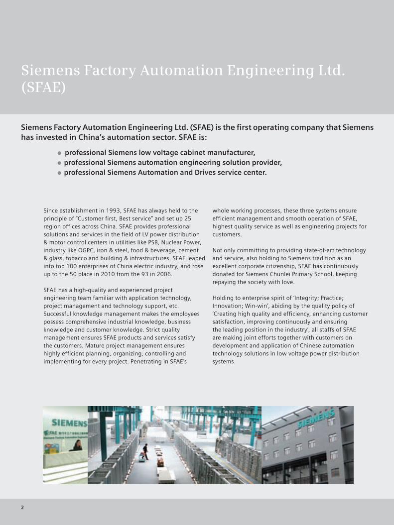
Siemens Factory Automation Engineering Ltd. (SFAE)
Siemens Factory Automation Engineering Ltd. (SFAE) is the first operating company that Siemens has invested in China’s automation sector. SFAE is:
professional Siemens low voltage cabinet manufacturer, professional Siemens automation engineering solution provider, professional Siemens Automation and Drives service center.
Since establishment in 1993, SFAE has always held to the principle of “Customer first, Best service” and set up 25 region offices across China. SFAE provides professional solutions and services in the field of LV power distribution & motor control centers in utilities like PSB, Nuclear Power, industry like OGPC, iron & steel, food & beverage, cement & glass, tobacco and building & infrastructures. SFAE leaped into top 100 enterprises of China electric industry, and rose up to the 50 place in 2010 from the 93 in 2006.
SFAE has a high-quality and experienced project engineering team familiar with application technology, project management and technology support, etc.Successful knowledge management makes the employees possess comprehensive industrial knowledge, business knowledge and customer knowledge. Strict quality management ensures SFAE products and services satisfy the customers. Mature project management ensures highly efficient planning, organizing, controlling and implementing for every project. Penetrating in SFAE‘s
whole working processes, these three systems ensure efficient management and smooth operation of SFAE, highest quality service as well as engineering projects for customers.
Not only committing to providing state-of-art technology and service, also holding to Siemens tradition as an excellent corporate citizenship, SFAE has continuously donated for Siemens Chunlei Primary School, keeping repaying the society with love.
Holding to enterprise spirit of ‘Integrity; Practice; Innovation; Win-win’, abiding by the quality policy of ‘Creating high quality and efficiency, enhancing customer satisfaction, improving continuously and ensuring the leading position in the industry’, all staffs of SFAE are making joint efforts together with customers on development and application of Chinese automation technology solutions in low voltage power distribution systems.
2
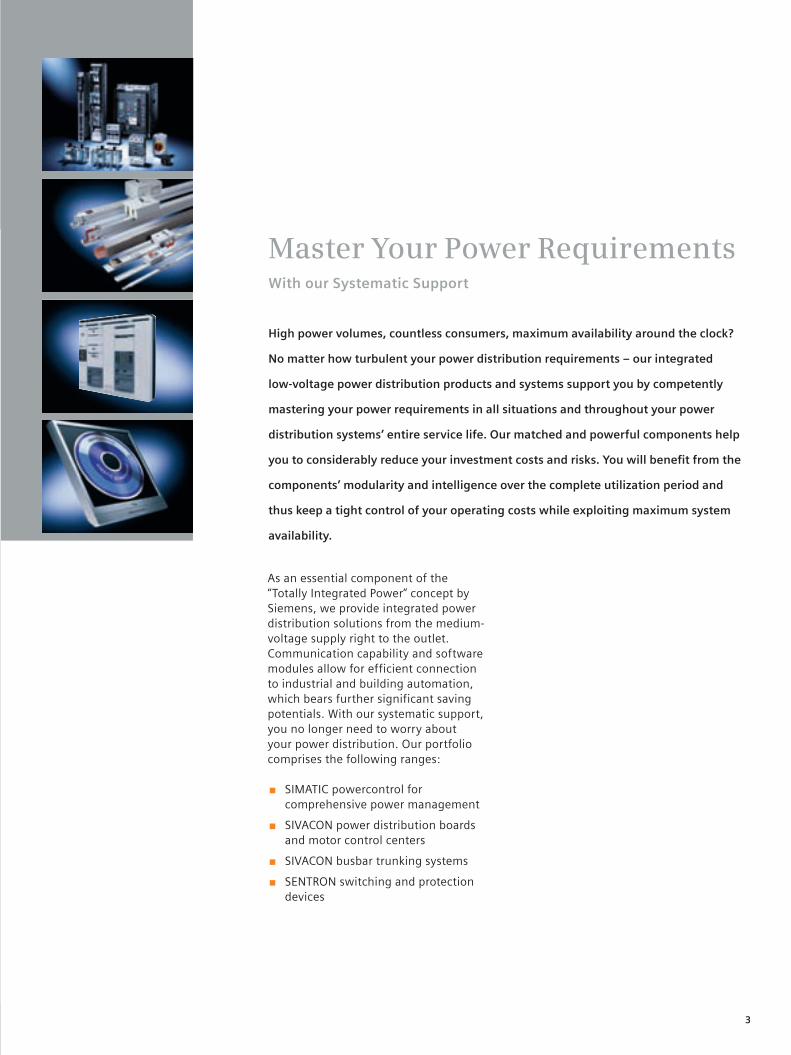
Master Your Power RequirementsWith our Systematic Support
As an essential component of the “Totally Integrated Power” concept by Siemens, we provide integrated power distribution solutions from the medium-voltage supply right to the outlet. Communication capability and software modules allow for efficient connection to industrial and building automation, which bears further significant saving potentials. With our systematic support, you no longer need to worry about your power distribution. Our portfolio comprises the following ranges:
■ SIMATIC powercontrol for comprehensive power management
■ SIVACON power distribution boards and motor control centers
■ SIVACON busbar trunking systems
■ SENTRON switching and protection devices
High power volumes, countless consumers, maximum availability around the clock?
No matter how turbulent your power distribution requirements – our integrated
low-voltage power distribution products and systems support you by competently
mastering your power requirements in all situations and throughout your power
distribution systems’ entire service life. Our matched and powerful components help
you to considerably reduce your investment costs and risks. You will benefit from the
components’ modularity and intelligence over the complete utilization period and
thus keep a tight control of your operating costs while exploiting maximum system
availability.
3
4
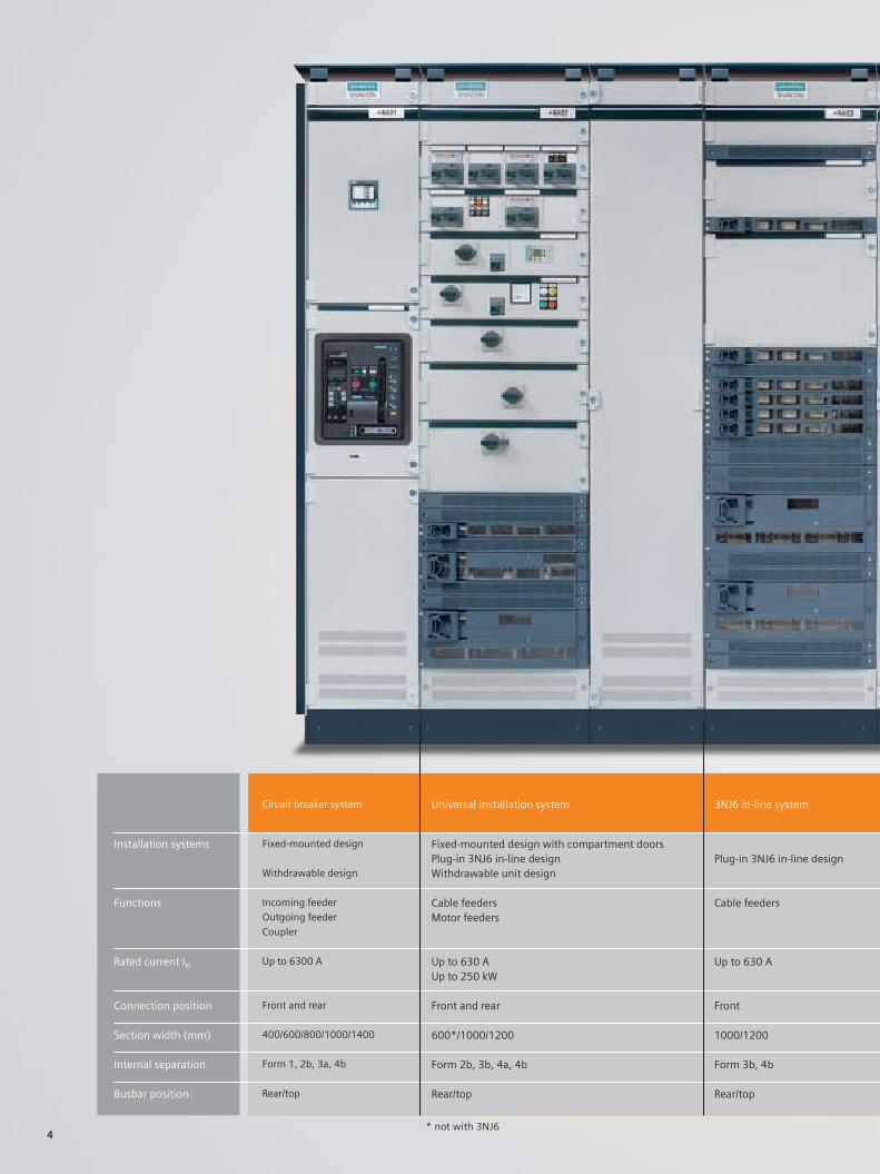
Installation systems
Functions
Rated current In
Connection position
Section width (mm)
Internal separation
Busbar position
Circuit breaker system
Fixed-mounted design
Withdrawable design
Incoming feeder
Outgoing feeder
Coupler
Up to 6300 A
Front and rear
400/600/800/1000/1400
Form 1, 2b, 3a, 4b
Rear/top
Universal installation system
Fixed-mounted design with compartment doorsPlug-in 3NJ6 in-line designWithdrawable unit design
Cable feedersMotor feeders
Up to 630 AUp to 250 kW
Front and rear
600*/1000/1200
Form 2b, 3b, 4a, 4b
Rear/top
3NJ6 in-line system
Plug-in 3NJ6 in-line design
Cable feeders
Up to 630 A
Front
1000/1200
Form 3b, 4b
Rear/top
* not with 3NJ6
5
3NJ6 in-line system
Plug-in 3NJ6 in-line design
Cable feeders
Up to 630 A
Front
1000/1200
Form 3b, 4b
Rear/top
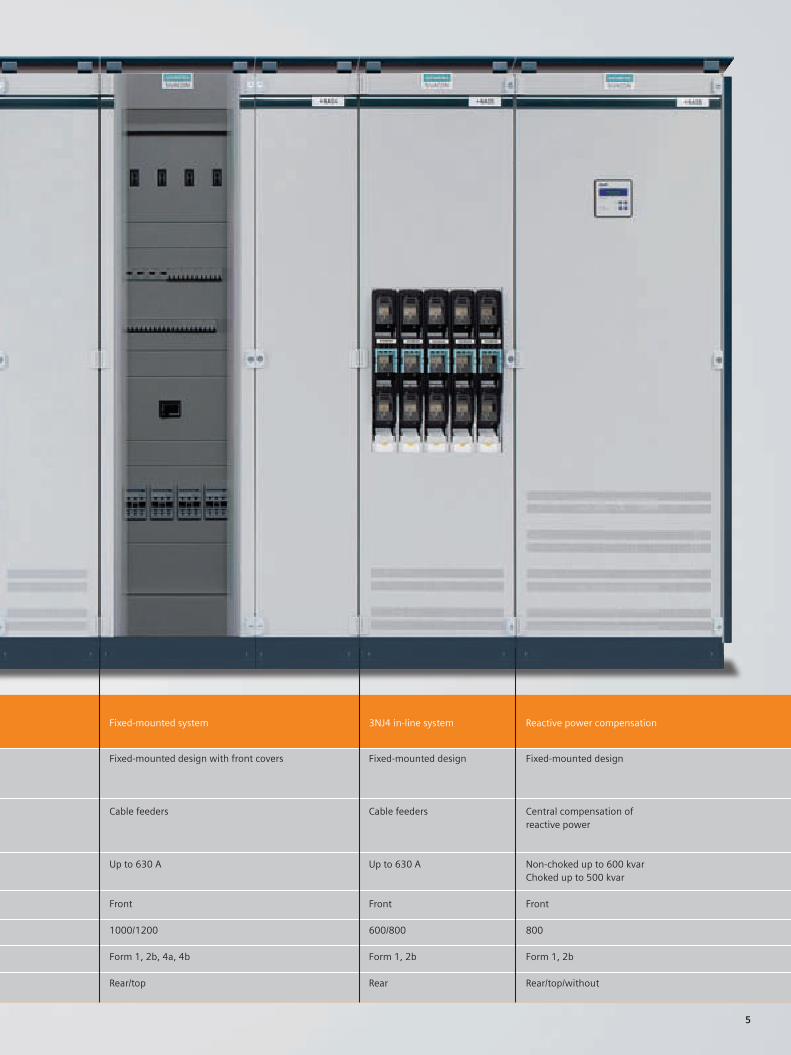
Fixed-mounted system
Fixed-mounted design with front covers
Cable feeders
Up to 630 A
Front
1000/1200
Form 1, 2b, 4a, 4b
Rear/top
3NJ4 in-line system
Fixed-mounted design
Cable feeders
Up to 630 A
Front
600/800
Form 1, 2b
Rear
Reactive power compensation
Fixed-mounted design
Central compensation of reactive power
Non-choked up to 600 kvarChoked up to 500 kvar
Front
800
Form 1, 2b
Rear/top/without
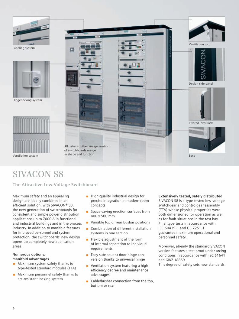
SIVACON S8The Attractive Low-Voltage Switchboard
■ High-quality industrial design for precise integration in modern room concepts
■ Space-saving erection surfaces from 400 x 500 mm
■ Variable top or rear busbar positions
■ Combination of different installation systems in one section
■ Flexible adjustment of the form of internal separation to individual requirements
■ Easy subsequent door hinge con-version thanks to universal hinge
■ Ventilation system featuring a high efficiency degree and maintenance advantages
■ Cable/busbar connection from the top, bottom or rear
Numerous options, manifold advantages
■ Maximum system safety thanks to type-tested standard modules (TTA)
■ Maximum personnel safety thanks to arc-resistant locking system
Labeling system
Hinge/locking system
Ventilation system Base
Pivoted lever lock
Design side panel
Ventilation roof
All details of the new generation of switchboards merge in shape and function
Extensively tested, safely distributedSIVACON S8 is a type-tested low-voltage switchgear and controlgear assembly (TTA) whose physical properties were both dimensioned for operation as well as for fault situations in the test bay. Final type tests in accordance with IEC 60439-1 and GB 7251.1guarantee maximum operational and personnel safety.
Moreover, already the standard SIVACON version features a test proof under arcing conditions in accordance with IEC 61641 and GB/Z 18859.This degree of safety sets new standards.
Maximum safety and an appealing design are ideally combined in an efficient solution: with SIVACON® S8, the new generation of switchboards for consistent and simple power distribution applications up to 7000 A in functional and industrial buildings and in the process industry. In addition to manifold features for improved personnel and system protection, the switchboards’ new design opens up completely new application areas.
6
7
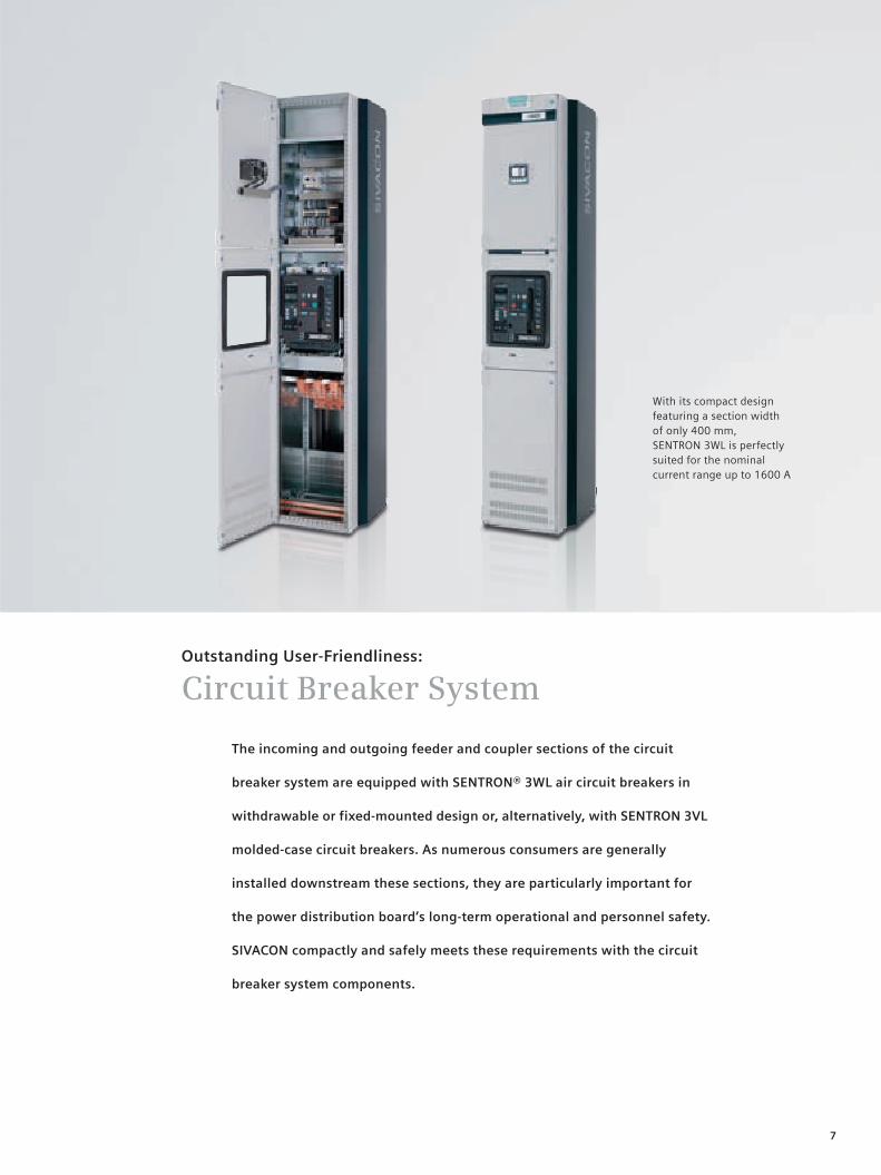
With its compact design featuring a section width of only 400 mm, SENTRON 3WL is perfectly suited for the nominal current range up to 1600 A
The incoming and outgoing feeder and coupler sections of the circuit
breaker system are equipped with SENTRON® 3WL air circuit breakers in
withdrawable or fixed-mounted design or, alternatively, with SENTRON 3VL
molded-case circuit breakers. As numerous consumers are generally
installed downstream these sections, they are particularly important for
the power distribution board’s long-term operational and personnel safety.
SIVACON compactly and safely meets these requirements with the circuit
breaker system components.
Outstanding User-Friendliness:
Circuit Breaker System
8
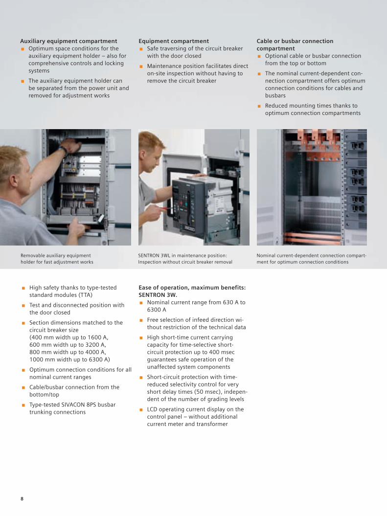
Auxiliary equipment compartment ■ Optimum space conditions for the
auxiliary equipment holder – also for comprehensive controls and locking systems
■ The auxiliary equipment holder can be separated from the power unit and removed for adjustment works
Equipment compartment ■ Safe traversing of the circuit breaker
with the door closed
■ Maintenance position facilitates direct on-site inspection without having to remove the circuit breaker
Cable or busbar connection compartment
■ Optional cable or busbar connection from the top or bottom
■ The nominal current-dependent con-nection compartment offers optimum connection conditions for cables and busbars
■ Reduced mounting times thanks to optimum connection compartments
Removable auxiliary equipment holder for fast adjustment works
SENTRON 3WL in maintenance position: Inspection without circuit breaker removal
Nominal current-dependent connection compart-ment for optimum connection conditions
■ High safety thanks to type-tested standard modules (TTA)
■ Test and disconnected position with the door closed
■ Section dimensions matched to the circuit breaker size (400 mm width up to 1600 A, 600 mm width up to 3200 A, 800 mm width up to 4000 A, 1000 mm width up to 6300 A)
■ Optimum connection conditions for all nominal current ranges
■ Cable/busbar connection from the bottom/top
■ Type-tested SIVACON 8PS busbar trunking connections
Ease of operation, maximum benefits: SENTRON 3W.
■ Nominal current range from 630 A to 6300 A
■ Free selection of infeed direction wi-thout restriction of the technical data
■ High short-time current carrying capacity for time-selective short-circuit protection up to 400 msec guarantees safe operation of the unaffected system components
■ Short-circuit protection with time-reduced selectivity control for very short delay times (50 msec), indepen-dent of the number of grading levels
■ LCD operating current display on the control panel – without additional current meter and transformer
9
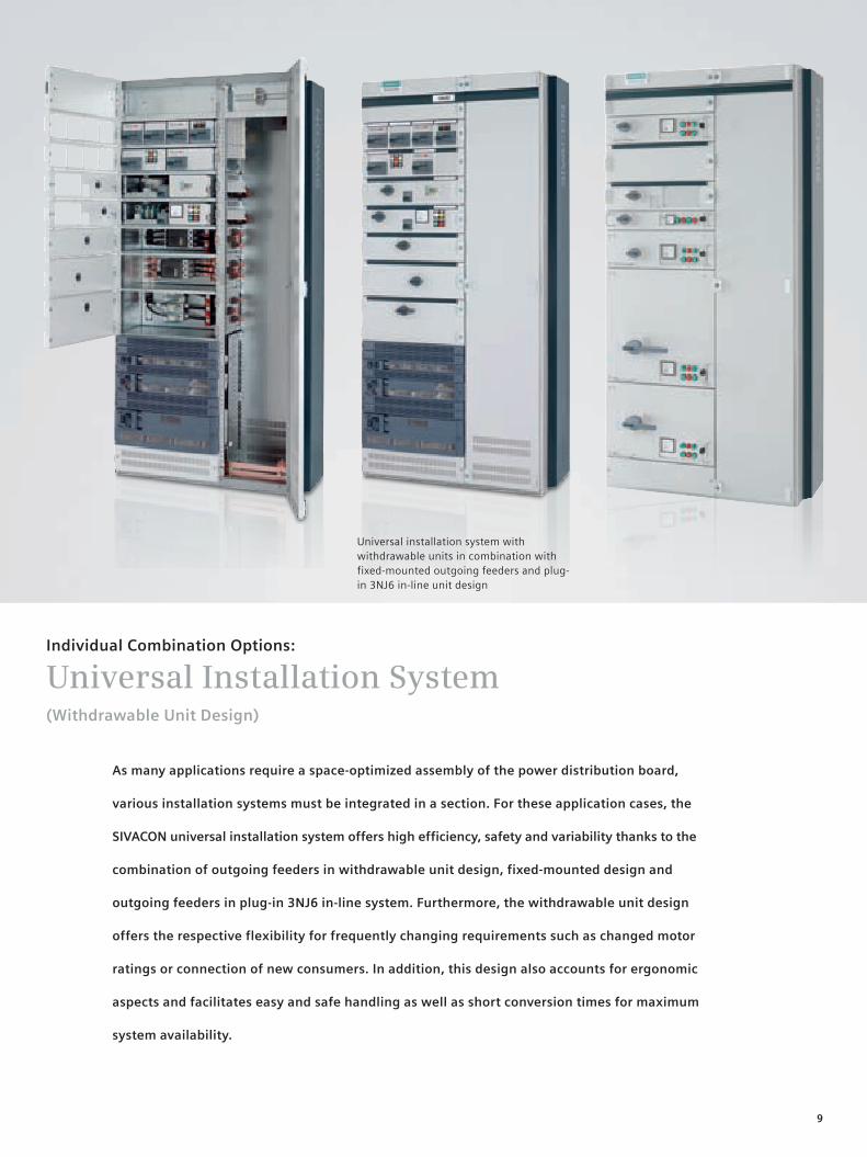
As many applications require a space-optimized assembly of the power distribution board,
various installation systems must be integrated in a section. For these application cases, the
SIVACON universal installation system offers high efficiency, safety and variability thanks to the
combination of outgoing feeders in withdrawable unit design, fixed-mounted design and
outgoing feeders in plug-in 3NJ6 in-line system. Furthermore, the withdrawable unit design
offers the respective flexibility for frequently changing requirements such as changed motor
ratings or connection of new consumers. In addition, this design also accounts for ergonomic
aspects and facilitates easy and safe handling as well as short conversion times for maximum
system availability.
Individual Combination Options:
Universal Installation System(Withdrawable Unit Design)
Universal installation system with withdrawable units in combination with fixed-mounted outgoing feeders and plug-in 3NJ6 in-line unit design
Optional (depends on design) ■ Shutters for miniature with drawable units
10
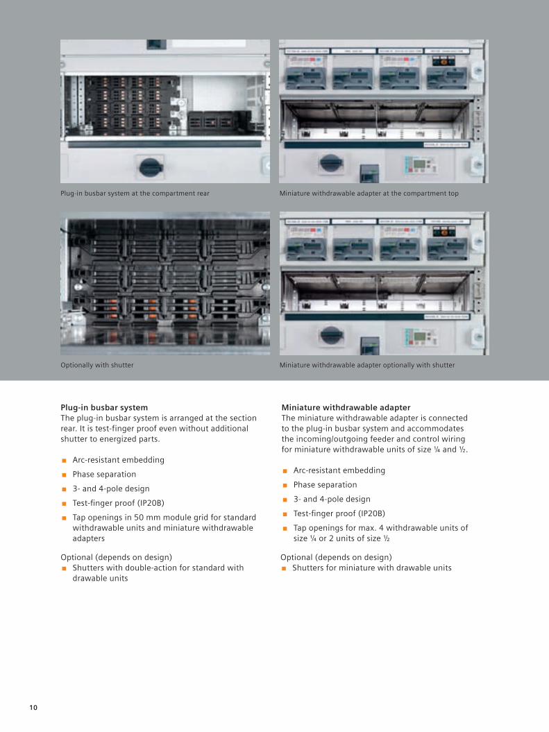
Optionally with shutter
Plug-in busbar systemThe plug-in busbar system is arranged at the section rear. It is test-finger proof even without additional shutter to energized parts.
■ Arc-resistant embedding
■ Phase separation
■ 3- and 4-pole design
■ Test-finger proof (IP20B)
■ Tap openings in 50 mm module grid for standard withdrawable units and miniature withdrawable adapters
Miniature withdrawable adapter optionally with shutter
Plug-in busbar system at the compartment rear Miniature withdrawable adapter at the compartment top
Miniature withdrawable adapterThe miniature withdrawable adapter is connected to the plug-in busbar system and accommodates the incoming/outgoing feeder and control wiring for miniature withdrawable units of size ¼ and ½.
■ Arc-resistant embedding
■ Phase separation
■ 3- and 4-pole design
■ Test-finger proof (IP20B)
■ Tap openings for max. 4 withdrawable units of size ¼ or 2 units of size ½
Optional (depends on design) ■ Shutters with double-action for standard with
drawable units
11
■ High safety thanks to type-tested standard modules (TTA)
■ Withdrawable unit sizes matched to power ratings (miniature, standard withdrawable units)
■ All parts are arranged within the with-drawable unit contours – protection against damage
■ Integrated operation error protection for all withdrawable units
■ Clear indication of the withdrawable unit positions
■ Separate operation for main switch and withdrawable unit position
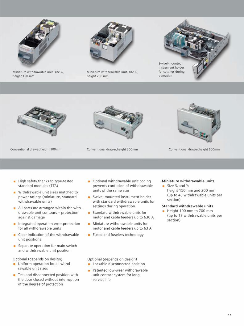
Miniature withdrawable units ■ Size ¼ and ½
height 150 mm and 200 mm (up to 48 withdrawable units per section)
Standard withdrawable units ■ Height 100 mm to 700 mm
(up to 18 withdrawable units per section)
■ Optional withdrawable unit coding prevents confusion of withdrawable units of the same size
■ Swivel-mounted instrument holder with standard withdrawable units for settings during operation
■ Standard withdrawable units for motor and cable feeders up to 630 A
■ Miniature withdrawable units for motor and cable feeders up to 63 A
■ Fused and fuseless technology
Conventional drawer,height 100mm
Miniature withdrawable unit, size ¼, height 150 mm
Miniature withdrawable unit, size ½, height 200 mm
Swivel-mounted instrument holder for settings during operation
Conventional drawer,height 300mm Conventional drawer,height 600mm
Optional (depends on design) ■ Uniform operation for all withd
rawable unit sizes
■ Test and disconnected position with the door closed without interruption of the degree of protection
Optional (depends on design) ■ Lockable disconnected position
■ Patented low-wear withdrawable unit contact system for long service life
12
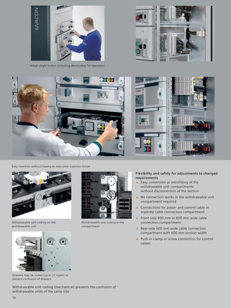
Withdrawable unit coding (mechanical) prevents the confusion of withdrawable units of the same size
Easy insertion without having to overcome insertion forces
Adopt single button unlocking device,easy for operation
Withdrawable unit coding in the compartment
Withdrawable unit coding on the withdrawable unit
Drawers may be coded (up to 21 types) to prevent confusion of drawers
Flexibility and safety for adjustments to changed requirements
■ Easy conversion or retrofitting of the withdrawable unit compartments without disconnection of the section
■ No connection works in the withdrawable unit compartment required
■ Connections for power and control cable in separate cable connection compartment
■ Front-side 400 mm or 600 mm wide cable connection compartment
■ Rear-side 600 mm wide cable connection compartment with 600 mm section width
■ Push-in clamp or screw connection for control cables
13
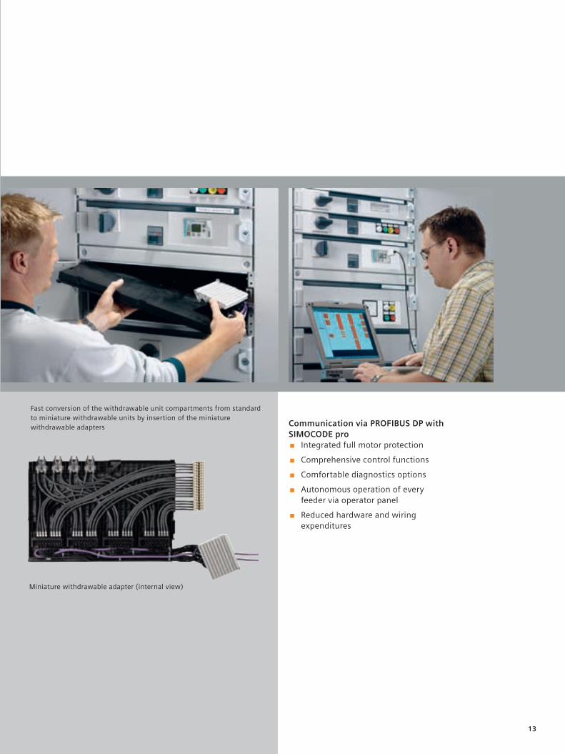
Communication via PROFIBUS DP with SIMOCODE pro
■ Integrated full motor protection
■ Comprehensive control functions
■ Comfortable diagnostics options
■ Autonomous operation of every feeder via operator panel
■ Reduced hardware and wiring expenditures
Fast conversion of the withdrawable unit compartments from standard to miniature withdrawable units by insertion of the miniature withdrawable adapters
Miniature withdrawable adapter (internal view)
14
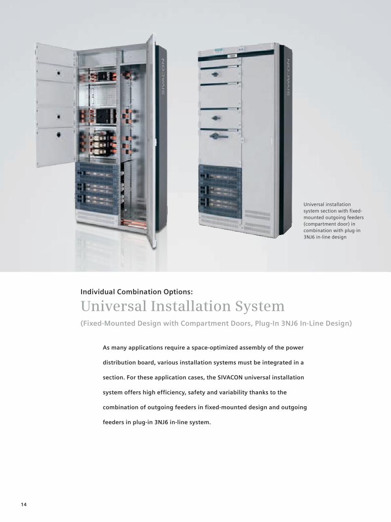
As many applications require a space-optimized assembly of the power
distribution board, various installation systems must be integrated in a
section. For these application cases, the SIVACON universal installation
system offers high efficiency, safety and variability thanks to the
combination of outgoing feeders in fixed-mounted design and outgoing
feeders in plug-in 3NJ6 in-line system.
Individual Combination Options:
Universal Installation System(Fixed-Mounted Design with Compartment Doors, Plug-In 3NJ6 In-Line Design)
Universal installation system section with fixed-mounted outgoing feeders (compartment door) in combination with plug-in 3NJ6 in-line design
15
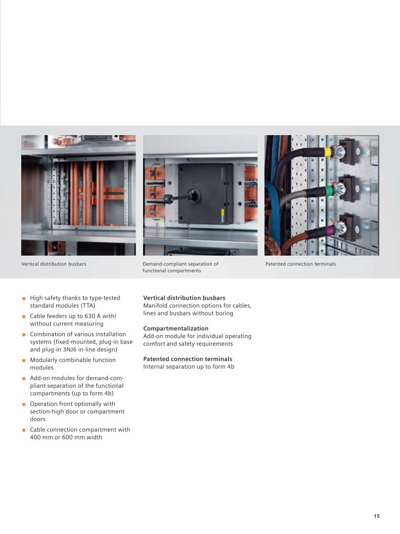
Vertical distribution busbarsManifold connection options for cables, lines and busbars without boring
CompartmentalizationAdd-on module for individual operating comfort and safety requirements
Patented connection terminalsInternal separation up to form 4b
■ High safety thanks to type-tested standard modules (TTA)
■ Cable feeders up to 630 A with/ without current measuring
■ Combination of various installation systems (fixed-mounted, plug-in base and plug-in 3NJ6 in-line design)
■ Modularly combinable function modules
■ Add-on modules for demand-com-pliant separation of the functional compartments (up to form 4b)
■ Operation front optionally with section-high door or compartment doors
■ Cable connection compartment with 400 mm or 600 mm width
Vertical distribution busbars Demand-compliant separation of functional compartments
Patented connection terminals
16
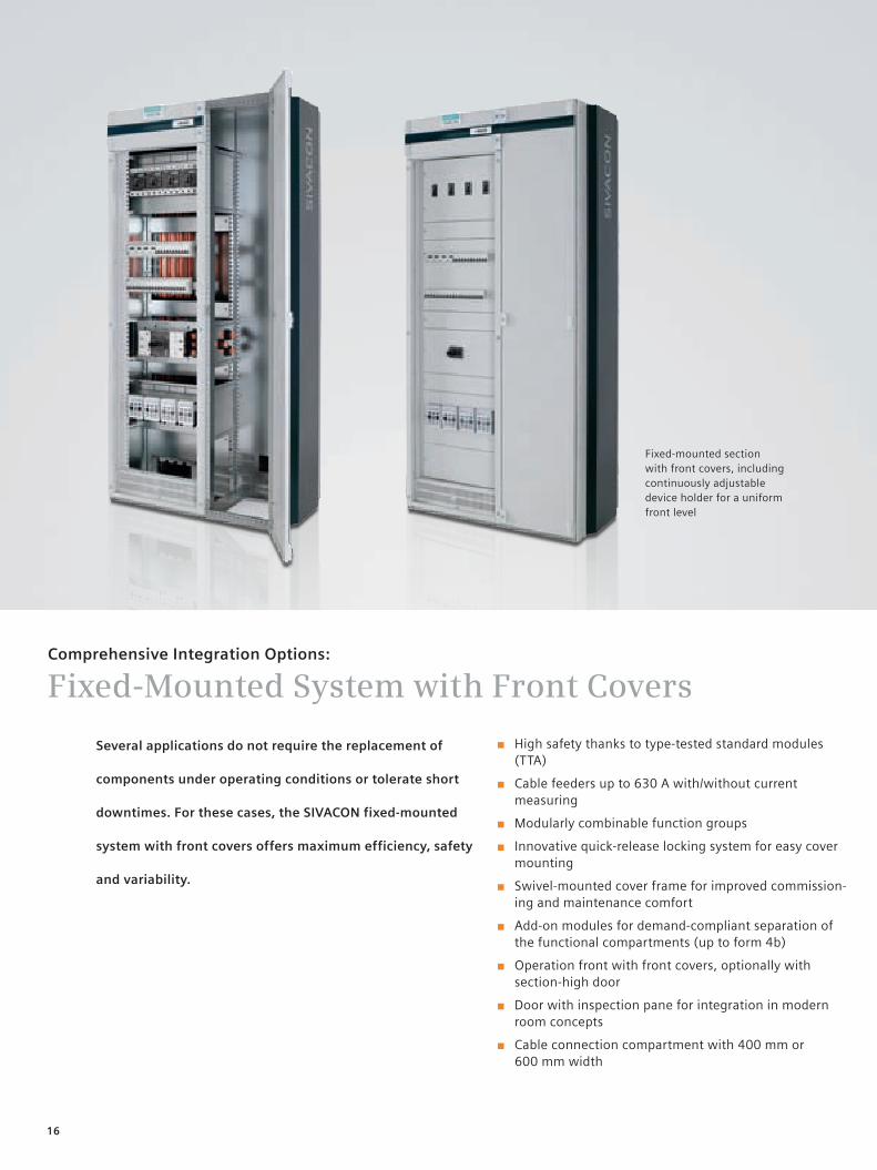
Several applications do not require the replacement of
components under operating conditions or tolerate short
downtimes. For these cases, the SIVACON fixed-mounted
system with front covers offers maximum efficiency, safety
and variability.
Comprehensive Integration Options:
Fixed-Mounted System with Front Covers
Fixed-mounted section with front covers, including continuously adjustable device holder for a uniform front level
■ High safety thanks to type-tested standard modules (TTA)
■ Cable feeders up to 630 A with/without current measuring
■ Modularly combinable function groups
■ Innovative quick-release locking system for easy cover mounting
■ Swivel-mounted cover frame for improved commission-ing and maintenance comfort
■ Add-on modules for demand-compliant separation of the functional compartments (up to form 4b)
■ Operation front with front covers, optionally with section-high door
■ Door with inspection pane for integration in modern room concepts
■ Cable connection compartment with 400 mm or 600 mm width
Duis autem vel eum iriure dolor in hendrerit in vulputate velit esse molestie consequat vel illum dolore eu feugidgat nulla facilisis at vero eros et accum. San et iusto odio dign iss im qui blandit prgdaesent luptatum.
17
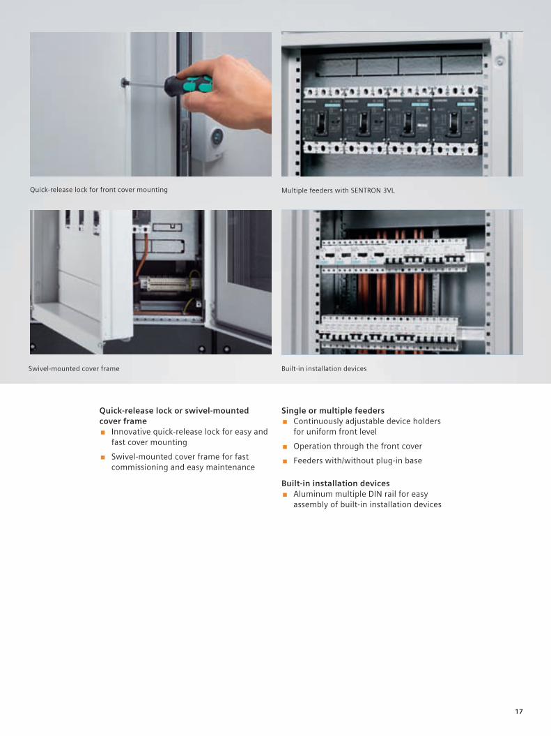
Quick-release lock or swivel-mounted cover frame
■ Innovative quick-release lock for easy and fast cover mounting
■ Swivel-mounted cover frame for fast commissioning and easy maintenance
Single or multiple feeders ■ Continuously adjustable device holders
for uniform front level
■ Operation through the front cover
■ Feeders with/without plug-in base
Built-in installation devices ■ Aluminum multiple DIN rail for easy
assembly of built-in installation devices
Quick-release lock for front cover mounting Multiple feeders with SENTRON 3VL
Built-in installation devicesSwivel-mounted cover frame
18
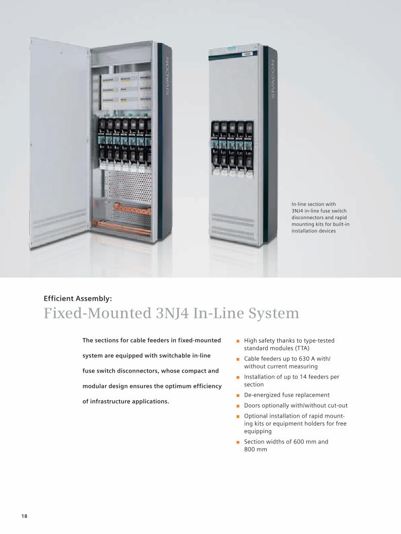
The sections for cable feeders in fixed-mounted
system are equipped with switchable in-line
fuse switch disconnectors, whose compact and
modular design ensures the optimum efficiency
of infrastructure applications.
Efficient Assembly:
Fixed-Mounted 3NJ4 In-Line System
■ High safety thanks to type-tested standard modules (TTA)
■ Cable feeders up to 630 A with/ without current measuring
■ Installation of up to 14 feeders per section
■ De-energized fuse replacement
■ Doors optionally with/without cut-out
■ Optional installation of rapid mount-ing kits or equipment holders for free equipping
■ Section widths of 600 mm and 800 mm
In-line section with 3NJ4 in-line fuse switch disconnectors and rapid mounting kits for built-in installation devices
19
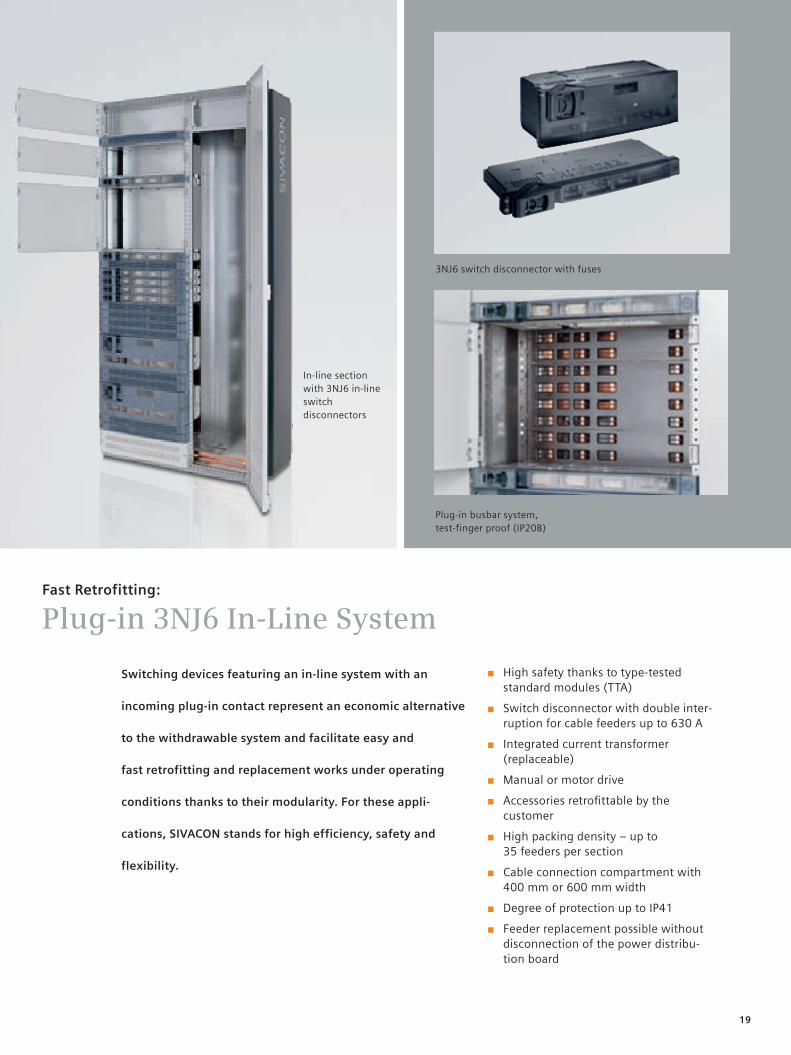
In-line section with 3NJ6 in-line switch disconnectors
■ High safety thanks to type-tested standard modules (TTA)
■ Switch disconnector with double inter-ruption for cable feeders up to 630 A
■ Integrated current transformer (replaceable)
■ Manual or motor drive
■ Accessories retrofittable by the customer
■ High packing density – up to 35 feeders per section
■ Cable connection compartment with 400 mm or 600 mm width
■ Degree of protection up to IP41
■ Feeder replacement possible without disconnection of the power distribu-tion board
Plug-in busbar system, test-finger proof (IP20B)
3NJ6 switch disconnector with fuses
Fast Retrofitting:
Plug-in 3NJ6 In-Line System
Switching devices featuring an in-line system with an
incoming plug-in contact represent an economic alternative
to the withdrawable system and facilitate easy and
fast retrofitting and replacement works under operating
conditions thanks to their modularity. For these appli-
cations, SIVACON stands for high efficiency, safety and
flexibility.
20
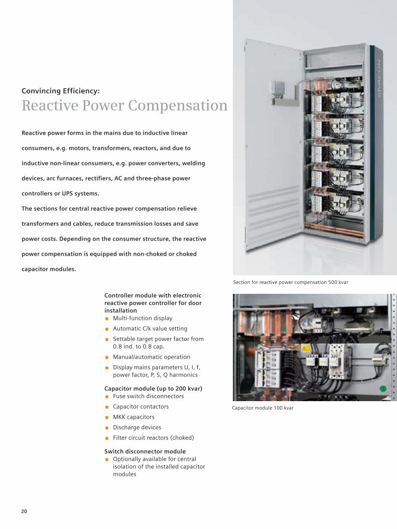
Convincing Efficiency:
Reactive Power Compensation
Section for reactive power compensation 500 kvar
Reactive power forms in the mains due to inductive linear
consumers, e.g. motors, transformers, reactors, and due to
inductive non-linear consumers, e.g. power converters, welding
devices, arc furnaces, rectifiers, AC and three-phase power
controllers or UPS systems.
The sections for central reactive power compensation relieve
transformers and cables, reduce transmission losses and save
power costs. Depending on the consumer structure, the reactive
power compensation is equipped with non-choked or choked
capacitor modules.
Capacitor module 100 kvar
Controller module with electronic reactive power controller for door installation
■ Multi-function display
■ Automatic C/k value setting
■ Settable target power factor from 0.8 ind. to 0.8 cap.
■ Manual/automatic operation
■ Display mains parameters U, I, f, power factor, P, S, Q harmonics
Capacitor module (up to 200 kvar) ■ Fuse switch disconnectors
■ Capacitor contactors
■ MKK capacitors
■ Discharge devices
■ Filter circuit reactors (choked)
Switch disconnector module ■ Optionally available for central
isolation of the installed capacitor modules
21
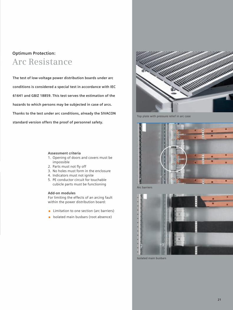
Optimum Protection:
Arc Resistance
The test of low-voltage power distribution boards under arc
conditions is considered a special test in accordance with IEC
61641 and GB/Z 18859. This test serves the estimation of the
hazards to which persons may be subjected in case of arcs.
Thanks to the test under arc conditions, already the SIVACON
standard version offers the proof of personnel safety.
Top plate with pressure relief in arc case
Arc barriers
Isolated main busbars
Assessment criteria1. Opening of doors and covers must be
impossible2. Parts must not fly off3. No holes must form in the enclosure4. Indicators must not ignite5. PE conductor circuit for touchable
cubicle parts must be functioning
Add-on modulesFor limiting the effects of an arcing fault within the power distribution board:
■ Limitation to one section (arc barriers)
■ Isolated main busbars (root absence)
22
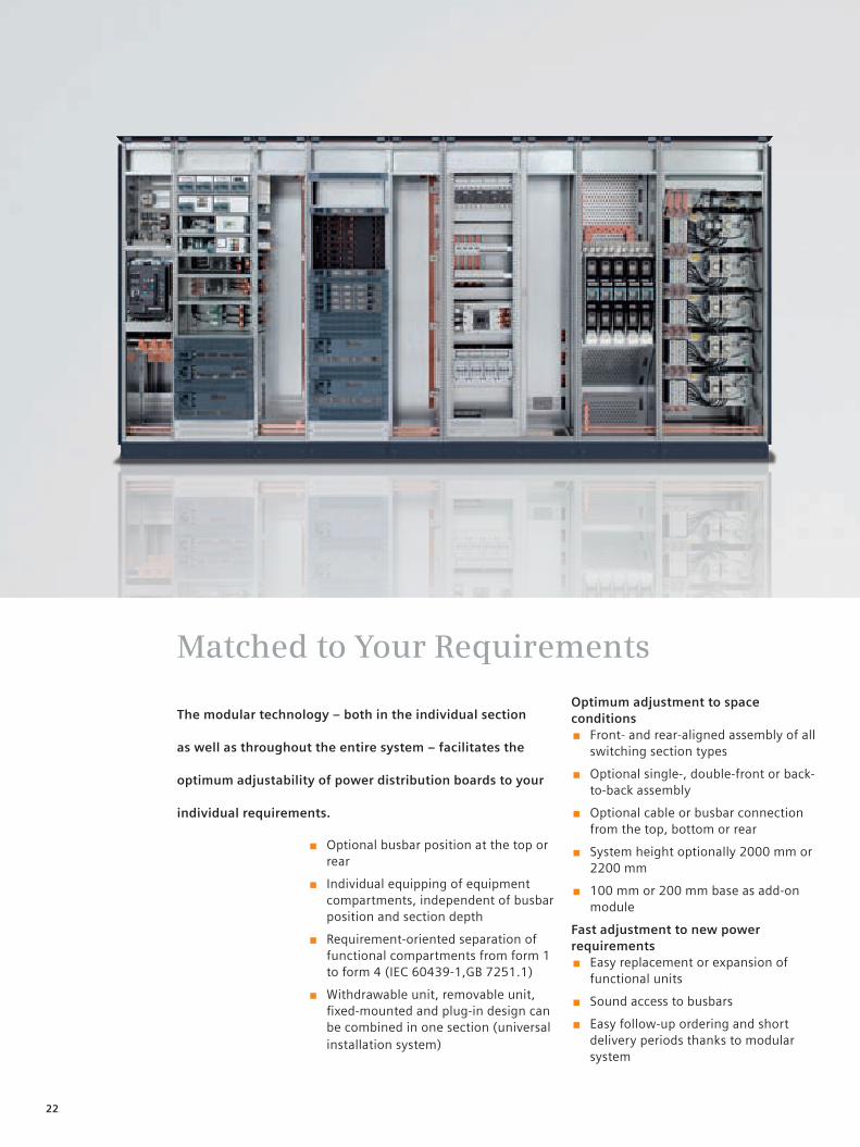
The modular technology – both in the individual section
as well as throughout the entire system – facilitates the
optimum adjustability of power distribution boards to your
individual requirements.
Matched to Your Requirements
■ Optional busbar position at the top or rear
■ Individual equipping of equipment compartments, independent of busbar position and section depth
■ Requirement-oriented separation of functional compartments from form 1 to form 4 (IEC 60439-1,GB 7251.1)
■ Withdrawable unit, removable unit, fixed-mounted and plug-in design can be combined in one section (universal installation system)
Optimum adjustment to space conditions
■ Front- and rear-aligned assembly of all switching section types
■ Optional single-, double-front or back-to-back assembly
■ Optional cable or busbar connection from the top, bottom or rear
■ System height optionally 2000 mm or 2200 mm
■ 100 mm or 200 mm base as add-on module
Fast adjustment to new power requirements
■ Easy replacement or expansion of functional units
■ Sound access to busbars
■ Easy follow-up ordering and short delivery periods thanks to modular system
23
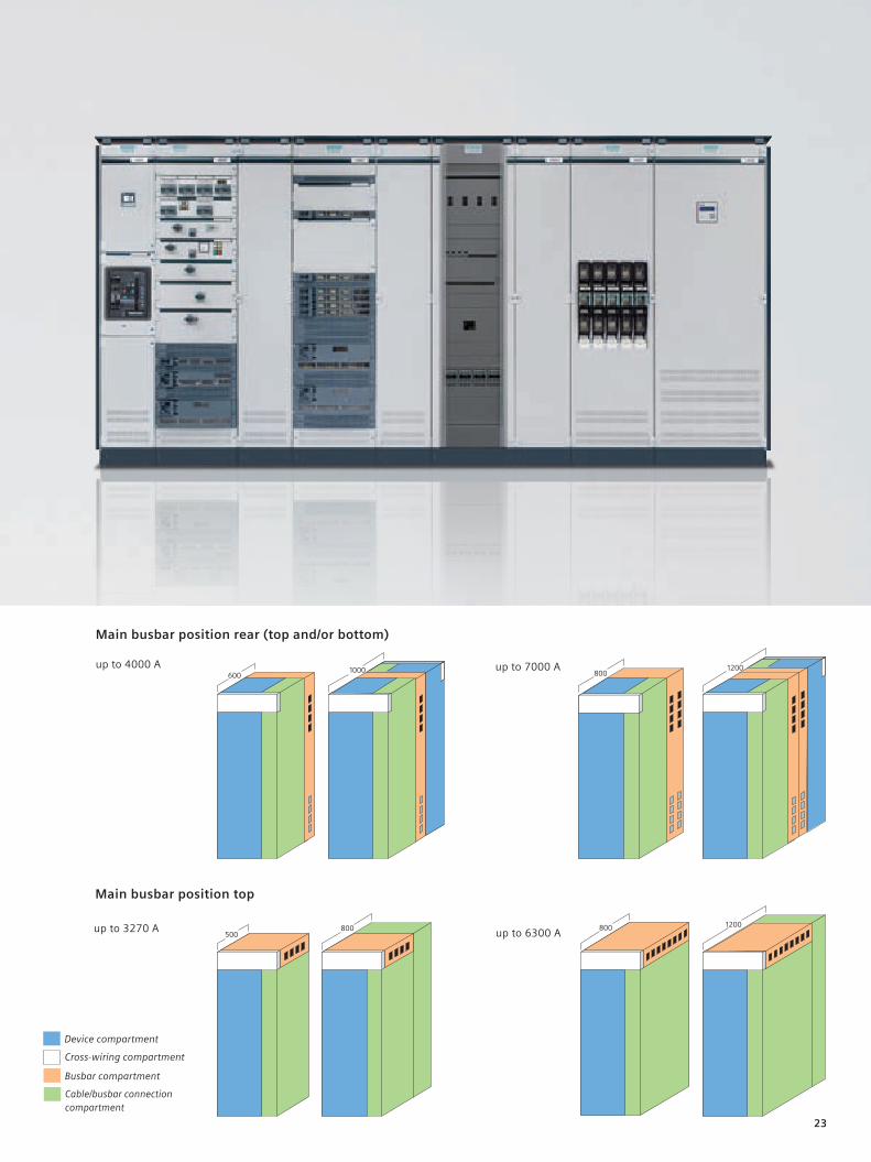
up to 3270 A
Main busbar position rear (top and/or bottom) up to 4000 A
Device compartment
Busbar compartment
Cross-wiring compartment
Cable/busbar connection compartment
12008001000
600up to 7000 A
up to 6300 A
Main busbar position top
24
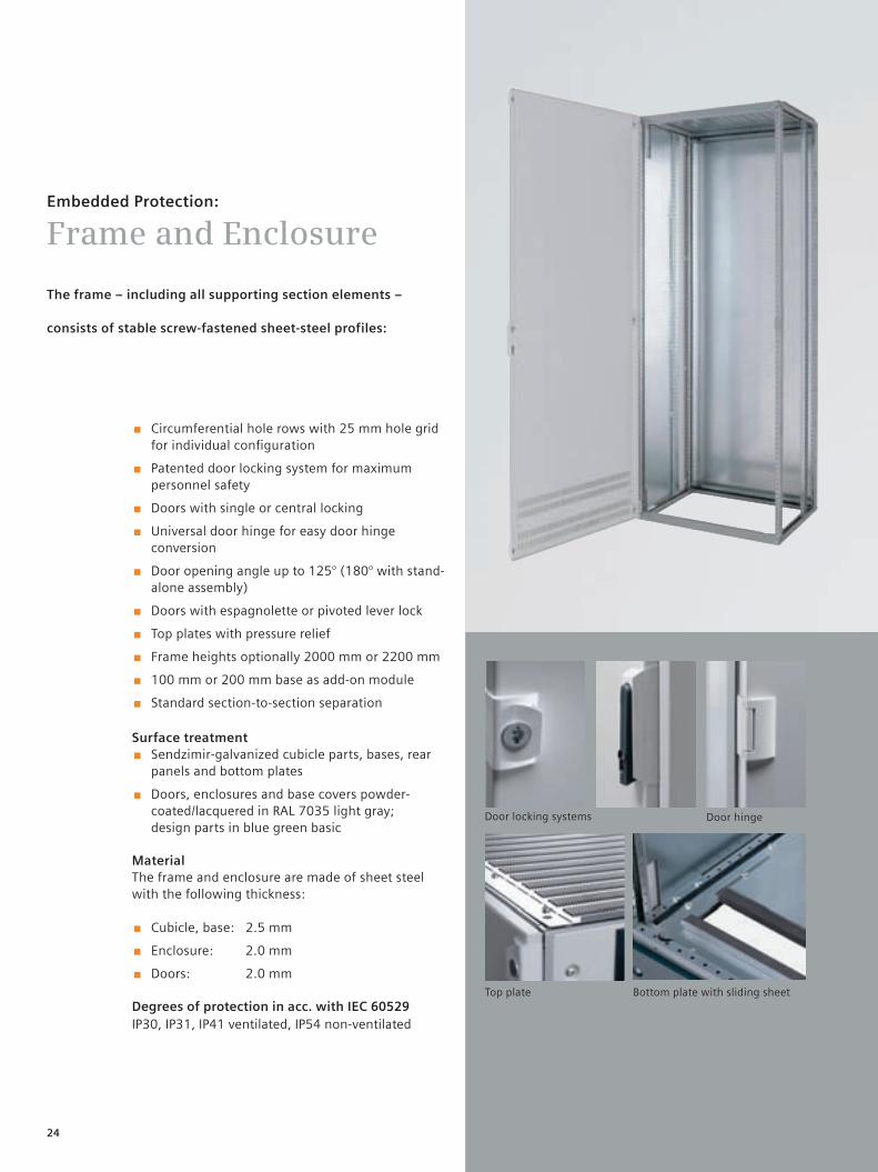
Embedded Protection:
Frame and Enclosure
The frame – including all supporting section elements –
consists of stable screw-fastened sheet-steel profiles:
Door locking systems
Top plate Bottom plate with sliding sheet
Door hinge
■ Circumferential hole rows with 25 mm hole grid for individual configuration
■ Patented door locking system for maximum personnel safety
■ Doors with single or central locking
■ Universal door hinge for easy door hinge conversion
■ Door opening angle up to 125° (180° with stand-alone assembly)
■ Doors with espagnolette or pivoted lever lock
■ Top plates with pressure relief
■ Frame heights optionally 2000 mm or 2200 mm
■ 100 mm or 200 mm base as add-on module
■ Standard section-to-section separation
Surface treatment ■ Sendzimir-galvanized cubicle parts, bases, rear
panels and bottom plates
■ Doors, enclosures and base covers powder- coated/lacquered in RAL 7035 light gray; design parts in blue green basic
MaterialThe frame and enclosure are made of sheet steel with the following thickness:
■ Cubicle, base: 2.5 mm
■ Enclosure: 2.0 mm
■ Doors: 2.0 mm
Degrees of protection in acc. with IEC 60529IP30, IP31, IP41 ventilated, IP54 non-ventilated
25
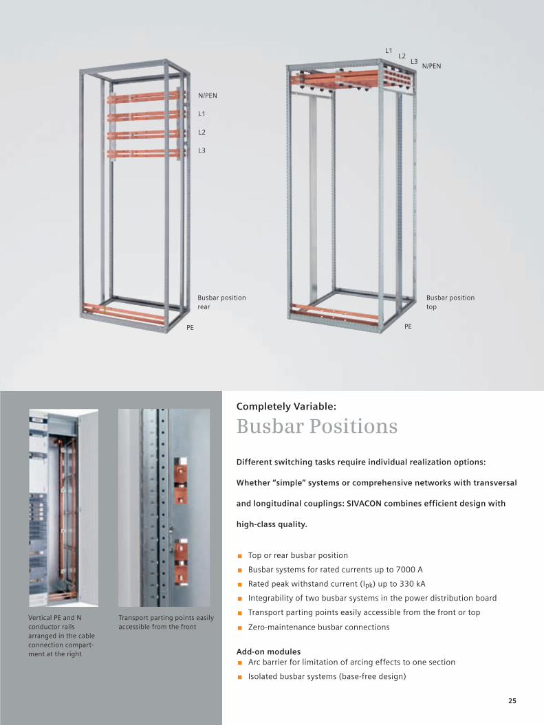
Completely Variable:
Busbar Positions
Different switching tasks require individual realization options:
Whether “simple” systems or comprehensive networks with transversal
and longitudinal couplings: SIVACON combines efficient design with
high-class quality.
■ Top or rear busbar position
■ Busbar systems for rated currents up to 7000 A
■ Rated peak withstand current (Ipk) up to 330 kA
■ Integrability of two busbar systems in the power distribution board
■ Transport parting points easily accessible from the front or top
■ Zero-maintenance busbar connections
Add-on modules ■ Arc barrier for limitation of arcing effects to one section
■ Isolated busbar systems (base-free design)
Vertical PE and N conductor rails arranged in the cable connection compart- ment at the right
Transport parting points easily accessible from the front
Busbar position rear
N/PEN
L1
L2
L3
PE PE
N/PENL3
L2L1
Busbar position top
26
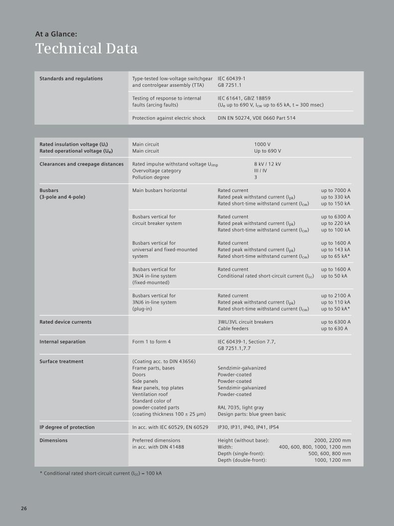
Standards and regulations Type-tested low-voltage switchgear IEC 60439-1 and controlgear assembly (TTA) GB 7251.1
Testing of response to internal IEC 61641, GB/Z 18859 faults (arcing faults) (Ue up to 690 V, Icw up to 65 kA, t = 300 msec)
Protection against electric shock DIN EN 50274, VDE 0660 Part 514
Rated insulation voltage (Ui) Main circuit 1000 VRated operational voltage (Ue) Main circuit Up to 690 V
Clearances and creepage distances Rated impulse withstand voltage Uimp 8 kV / 12 kV Overvoltage category III / IV Pollution degree 3 Busbars Main busbars horizontal Rated current up to 7000 A(3-pole and 4-pole) Rated peak withstand current (Ipk) up to 330 kA Rated short-time withstand current (Icw) up to 150 kA
Busbars vertical for Rated current up to 6300 A circuit breaker system Rated peak withstand current (Ipk) up to 220 kA Rated short-time withstand current (Icw) up to 100 kA
Busbars vertical for Rated current up to 1600 A universal and fixed-mounted Rated peak withstand current (Ipk) up to 143 kA system Rated short-time withstand current (Icw) up to 65 kA*
Busbars vertical for Rated current up to 1600 A 3NJ4 in-line system Conditional rated short-circuit current (Icc) up to 50 kA (fixed-mounted)
Busbars vertical for Rated current up to 2100 A 3NJ6 in-line system Rated peak withstand current (Ipk) up to 110 kA (plug-in) Rated short-time withstand current (Icw) up to 50 kA*
Rated device currents 3WL/3VL circuit breakers up to 6300 A Cable feeders up to 630 A
Internal separation Form 1 to form 4 IEC 60439-1, Section 7.7, GB 7251.1,7.7
Surface treatment (Coating acc. to DIN 43656) Frame parts, bases Sendzimir-galvanized Doors Powder-coated Side panels Powder-coated Rear panels, top plates Sendzimir-galvanized Ventilation roof Powder-coated Standard color of powder-coated parts RAL 7035, light gray (coating thickness 100 ± 25 µm) Design parts: blue green basic IP degree of protection In acc. with IEC 60529, EN 60529 IP30, IP31, IP40, IP41, IP54 Dimensions Preferred dimensions Height (without base): 2000, 2200 mm in acc. with DIN 41488 Width: 400, 600, 800, 1000, 1200 mm Depth (single-front): 500, 600, 800 mm Depth (double-front): 1000, 1200 mm
* Conditional rated short-circuit current (Icc) = 100 kA
At a Glance:
Technical Data
27
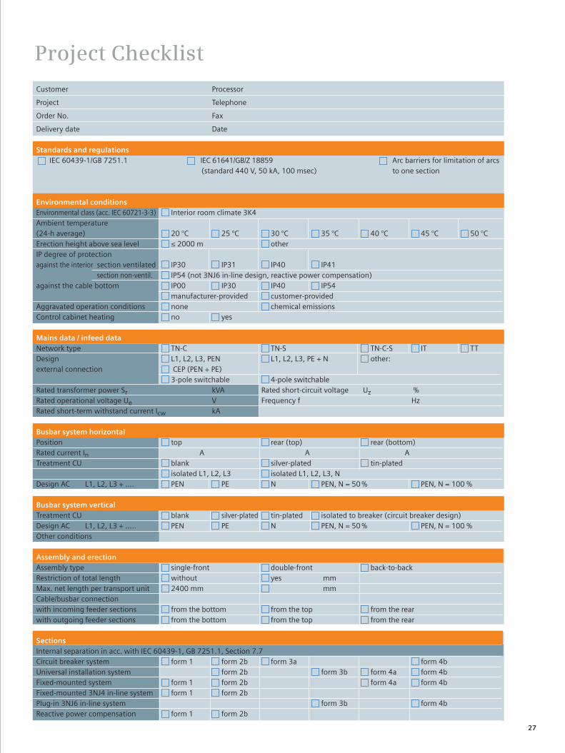
Project Checklist
Customer Processor
Project Telephone
Order No. Fax
Delivery date Date
Standards and regulations IEC 60439-1/GB 7251.1 IEC 61641/GB/Z 18859 Arc barriers for limitation of arcs
(standard 440 V, 50 kA, 100 msec) to one section
Environmental conditionsEnvironmental class (acc. IEC 60721-3-3) Interior room climate 3K4 Ambient temperature (24-h average) 20 °C 25 °C 30 °C 35 °C 40 °C 45 °C 50 °CErection height above sea level ≤ 2000 m other IP degree of protectionagainst the interior section ventilated IP30 IP31 IP40 IP41 section non-ventil. IP54 (not 3NJ6 in-line design, reactive power compensation)against the cable bottom IP00 IP30 IP40 IP54 manufacturer-provided customer-providedAggravated operation conditions none chemical emissionsControl cabinet heating no yes
Mains data / infeed dataNetwork type TN-C TN-S TN-C-S IT TT Design L1, L2, L3, PEN L1, L2, L3, PE + N other: external connection CEP (PEN + PE) 3-pole switchable 4-pole switchableRated transformer power Sr kVA Rated short-circuit voltage Uz %Rated operational voltage Ue V Frequency f HzRated short-term withstand current Icw kA
Busbar system horizontalPosition top rear (top) rear (bottom) Rated current In A A A Treatment CU blank silver-plated tin-plated isolated L1, L2, L3 isolated L1, L2, L3, N Design AC L1, L2, L3 + .... PEN PE N PEN, N = 50 % PEN, N = 100 % Busbar system verticalTreatment CU blank silver-plated tin-plated isolated to breaker (circuit breaker design)Design AC L1, L2, L3 + ..... PEN PE N PEN, N = 50 % PEN, N = 100 %Other conditions Assembly and erectionAssembly type single-front double-front back-to-back Restriction of total length without yes mmMax. net length per transport unit 2400 mm mmCable/busbar connectionwith incoming feeder sections from the bottom from the top from the rearwith outgoing feeder sections from the bottom from the top from the rear
SectionsInternal separation in acc. with IEC 60439-1, GB 7251.1, Section 7.7 Circuit breaker system form 1 form 2b form 3a form 4bUniversal installation system form 2b form 3b form 4a form 4bFixed-mounted system form 1 form 2b form 4a form 4bFixed-mounted 3NJ4 in-line system form 1 form 2b Plug-in 3NJ6 in-line system form 3b form 4bReactive power compensation form 1 form 2b
西门子公司版权所有。如有改动,恕不事先通知
Copyright Siemens. All rights reserved.It's subject to change without notice.
It's subject to change without notice.www.ad.siemens.com.cn/sfae
Siemens Factory Automation Engineering Ltd.
Order No.: E20001-A-0066-C1000-V2-6C001115-F905810-11095
Siemens Factory Automation Engineering Ltd.(SFAE)
SFAE Headquarter Beijing
7/F, A1 Building, No.9 Jiuxianqiao East Rd., Chaoyang District,Beijing, 100015, P.R. China
Tel: (0086-10) 8459 7212
Fax: (0086-10) 8459 7184
SFAE Hangzhou Office
RM1710, 15/F Jiahua International Business Center, No.15 Hangda Road, Xihu District, Hangzhou, Zhejiang, 310007, P. R. China
Tel: (0086-571) 8765 2999
Fax: (0086-571) 8717 5234
SFAE Guangzhou Office
8-10/F Teemtower, Teemall 208 Tianhe Road, Tianhe District, Guangzhou, Guangdong Province, 510620, P. R. China
Tel: (0086-20) 3718 2043
Fax: (0086-20) 3718 2167
SFAE Ji‘nan Office
5/F, Shunhuayuan Commercial Club, No.28 Shungeng Rd, Jinan, Shandong Province, 250014, P. R. China
Tel: (0086-531) 8266 6088-6333
Fax: (0086-531) 8266 0836
Siemens Ltd. China (SLC)
Beijing Office
7 Wangjing Zhong Huan Nanlu, Chaoyang District, Beijing, 100102, P. R. China
Tel: (0086-10) 6476 5331
Fax: (0086-10) 6476 4834
Service & Support Hotline (Beijing)
Tel: (0086-10) 6471 9990 / 400-810-4288
Fax: (0086-10) 6471 9991
E-mail: [email protected]
SFAE Anshan Branch
No.452, QianAn Rd, Tiedong District, Anshan, Liaoning, 114010, P. R. China
Tel: (0086-412) 5581611-8015
Fax: (0086-412) 5260611
SFAE Nanjing Office
17/F, Metro Building, No.228 Zhongshan Rd., Xuanwu District, Nanjing, Jiangsu Province, 210008, P. R. China
Tel: (0086-25) 84560550-3677
Fax: (0086-25) 8451 1612
SFAE Shenyang Office
12/F, Tower E, Fortune Plaza, No.59 Beizhan Road, Shenhe District, Shenyang, 110013, P. R. China
Tel: (0086-24) 8251 8135
Fax: (0086-24) 8251 8599
SFAE Chengdu Office
2F North Wing,Building C6,Chengdu Tianfu Software Park, No.81 Tuo Xin Dong Jie, Gaoxin South District, Chengdu, Sichuan, 610041 P.R.China
Tel: (0086-28) 6238 7888-7913
Fax: (0086-28) 6238 7009
Shanghai Office
7/F, A Building, No.500 Dalian Road, Yangpu District, Shanghai, 200082, P. R. China
Tel: (0086-21) 3889 2664
Fax: (0086-21) 3889 2327
SFAE Shanghai Office
7/F, Xuhuiyuan Building, No.1089, Zhongshan No.2 South Rd., Xuhui District, Shanghai, 200030, P. R. China
Tel: (0086-21) 5412 0088-6505
Fax: (0086-21) 5412 9990
SFAE Wuhan Office
18/F, Jianyin Tower, No.709 Jianshe Avenue, Jianghan District, Wuhan, Hubei Province, 430015, P. R. China
Tel: (0086-27) 8548 6688-8016
Fax: (0086-27) 8548 6777
SFAE Changchun Office
RM 401, Shangri-la Hotel, No.569 Xi’an Avenue, Changchun, JilinProvince, 130061, P. R. China
Tel: (0086-431) 8898 1100-8168
Fax: (0086-431) 8898 1087
SFAE Kunming Office
Room 1204, 12/F, Hongta Building, No.155 Beijing Rd., Kunming, Yunnan Province, 650011, P. R. China
Tel: (0086-871) 315 8080-8325
Fax: (0086-871) 315 8093
Copyright Siemens. All rights reserved.Order No.E20001-A0360-C300-X-5D003036-X906133-06111It's subject to change without notice.
The information provided in this brochure contains merely general descrip-tions or characteristics of performance which in actual case of use do not always apply as described or which may change as a result of further deve-lopment of the products.An obligation to provide the respective characteri-stics shall only exist if expressly agreed in the terms of contract.All product designations may be trademarks or product names of Siemens AG or supplier companies whose use by third parties for theirown purposes could violate the rights of the owners.
西门子公司版权所有。如有改动,恕不事先通知
Copyright Siemens. All rights reserved.It's subject to change without notice.
It's subject to change without notice.www.ad.siemens.com.cn/sfae
Siemens Factory Automation Engineering Ltd.
Order No.: E20001-A-0066-C1000-V2-6C001115-F905810-11095