Embed Size (px)
Citation preview

Safety Instructions & Operator's Manual for
®
INTERMEDIATEREAR TINE TILLER
SERIES 4
MODELICFR5OO4B
MODEL NUMBER EXPLANATION
MODEL DESIGNATIONREAR TINE MODEL
ENGINE MODELSERIES DESIGNATION
ENGINE HP
I - Intermediate Size Model
C - Counter Rotating TinesF - Forward Rotating TinesR - Rear Tine Type Model
50 - 5 HP Engine (Horse Power) 4 - Series Designation B - Briggs Engine
Thank you for buying a SNAPPER Product! Before operating your TILLER, read this manual carefully and payparticular attention to the "IMPORTANT SAFETY INSTRUCTIONS" on Page 2. Remember that all powerequipment can be dangerous if used improperly. Also keep in mind that SAFETY requires careful use inaccordance with the operating instructions and common sense!
SNAPPER McDonough, GA., 30253 U.S.A.
COPYRIGHT © 1999SNAPPER INC.ALL RIGHTS RESERVED
MANUAL No. 7-2130 (REV. 1, 4/30/99)

IMPORTANT SAFETY INSTRUCTIONS
WARNING: This powerful machine is capable of amputating hands and feet and can throw objects that cancause injury and damage! Failure to comply with the following instructions may result in serious injury to theoperator or other persons. The owner of the tiller must understand these instructions and, furthermore, mustallow only persons who understand these instructions to operate tiller. Each person operating the tiller must beof sound mind and body and must not be under the influence of any substance, which might impair vision,dexterity, or judgment. If you have any questions pertaining to your tiller which your dealer cannot answer toyour satisfaction, call or write the Customer Service Department at SNAPPER, McDonough, Georgia, 30253.Phone: (1-800-935-2967).
PROTECTION FOR CHILDREN OPERATIONAL PRECAUTIONS
1. DO NOT allow children in area when tiller isbeing operated.
2. DO NOT allow pre-teenage children to operatetiller.
3. Allow only responsible teenagers or adults withmature judgment to operate tiller and only underclose supervision.
4. Keep the area clear of all persons, particularlysmall children, and pets.
5. Know how to STOP the tiller and disengage thecontrols quickly.
PREPARATION
1. Read this manual, get to know where all controlsare located and practice how to use them beforestarting for the first time, and at the beginning ofeach season. Be thoroughly familiar with thecontrols and proper use of the equipment. Payattention to Warning and Instructional Decals onengine and tiller.
2. Never operate tiller without proper guards, dragshield, plates, safety switches, or other safetyprotective devices in place and properlyconnected. Inspect to determine that these safetydevices are installed properly, are in good repair,and operate properly. If the condition oroperation of these devices are questionable, theymust be repaired or replaced before using thetiller.
3. Thoroughly inspect the area where the tiller is tobe used and remove all stones, sticks, wire,bones and other foreign objects. Also, note thelocation of holes, stumps, and other possiblehazards.
4. DO NOT operate tiller when barefoot or wearingopen sandals. Always wear long pants andsubstantial footwear with good traction.
5. Fill fuel tank outdoors and replace fuel capbefore starting engine. Use approved fuelcontainer. DO NOT smoke near open fuelcontainer. DO NOT fill fuel tank indoors or whenengine is running. Allow engine to cool for atleast ten minutes before refilling. Wipe off anyspilled fuel before starting engine. DO NOT runengine indoors.
6. Make sure that clutch is disengaged andtransmission is in neutral (if so equipped) beforestarting engine.
1. DO NOT change engine governor settings orover speed engine.
2. DO NOT put hands or feet near or under rotatingparts.
3. Exercise CAUTION when crossing gravel drives,walks, or roads, and under any conditions whentiller is transported. Look behind and use carewhen backing.
4. After striking a foreign object or if tiller vibratesabnormally, STOP the engine, disconnect andsecure spark plug wire away from plug. Inspectthe tiller for any damage and repair the damage.
5. When leaving tiller unattended, disengage clutch,shift transmission to neutral (if so equipped) andstop the engine.
6. Before removing debris or cleaning tines,repairing or inspecting make certain engine,tines and all moving parts have STOPPED.Disconnect and secure spark plug wire awayfrom plug to prevent accidental starting.
7. Exercise CAUTION when changing directionswhile operating tiller. DO NOT till in areas wherestability or traction is in doubt.
8. DO NOT overload the machine capacity byattempting to till too deep at too fast a rate.
9. Be extra careful when tilling hard ground. Useless tine engagement to maintain control of tiller.
10. Till only in daylight or in good artificial light.11. Never operate tiller in wet areas. Always be sure
of your footing; keep a firm hold on the handle.12. Do not operate on slopes
MAINTENANCE AND STORAGE
1. Keep all nuts, bolts, and screws tight and be suretiller is in safe operating condition.
2. Never store tiller with fuel in tank inside of abuilding where fumes may reach an open flameor spark. Allow engine to cool before storing inany enclosure.
3. To reduce fire hazard, keep engine free of spilledfuel, debris and excessive grease.
4. Have your tiller inspected and serviced each yearby an authorized Snapper dealer. Determine ifany additional devices are available which mightupgrade the safety of your tiller.
5. Factory specified Snapper replacement partsmust be used to assure adequate protectionagainst injury.

TABLE OF CONTENTS
IMPORTANT SAFETY INSTRUCTIONS ................................................... 2
TABLE OF CONTENTS ............................................................................ 3
SECTION 1 - FAMILIARIZATION .............................................................. 4
SECTION 2 - OPERATING INSTRUCTIONS ......................................... 5-6Transmission Positions ............................................................... 5Pre-Start Checklist ........................................................................ 5
Starting & Stopping ................................................................... 5-6Handlebar Adjustment .................................................................. 6Transporting .................................................................................. 6Tilling Procedure ........................................................................... 6
SECTION 3 - ADJUSTMENTS & REPAIR ............................................. 7-9Service Parts & Assistance .......................................................... 7
Standing Tiller On End ................................................................. 7Tiller Lubrication ........................................................................... 7Tiller Tines ..................................................................................... 8
Belt Adjustment & Replacement .................................................. 8Off Season Storage ....................................................................... 9Tine Replacement ......................................................................... 9
WARRANTY ............................................................................................ 10
PRIMARY MAINTENANCE ................................................................ 11-14
NOTES .................................................................................................... 15

Section 1 - FAMILIARIZATION
CLUTCHCABLECOVER
DASHPANEL
HANDLE_
BRACKET
DEPTHBAR
HANDLEBAR
WHEEL&TINECONTROL BAIL
_WHEEL & TINESHIFT LEVER
SHIFT COVER
SPEED CONTROLLEFT SIDE SHOWN TOVIEW CHECK PLUG
ENGINE AIR FILTER
CONTROL
MAIN CASE GRCHECK PLUG
ENGINE
TINECOVER
DRAG
MAIN CASEFILL PLUG
ODRIVEBELTGUARD
ENGINE OILCHECK/FILLPLUG
OIL DRAINPLUG
TINE
STARTER ROPE, WEIGHTBOX
TIRE & WHEEL. TRANSMISSION STAND-UPCHAIN CASE BAR
FIGURE 1
1.1 INTRODUCTION: This manual covers the recommended operating procedure and routine servicerequirements on SNAPPER Intermediate Rear Tine Tiller. It is recommended that all operators of this Tillerbecome thoroughly familiar with the controls and proper operation of the unit before operating. Specificdetails involving the engine are found in the separate engine owner's manual. Study these manuals beforeoperating and keep both handy for future reference. Refer to Figure 1 above for location of controls andother essential components.

Section 2 - OPERATING INSTRUCTIONS
2.1 BEFORE OPERATING:Be thoroughly familiar with the operation of ALL controls andhow to use them BEFORE operating your Tiller.Transmission shifting is done by shifting the WHEEL andTINE SHIFT LEVER into the desired position. See Figure 3.
2.1.1 TRANSMISSION POSITIONS: The tiller has fivedifferent transmission positions. They are as viewed fromthe operator's position, viewed from the left to right asfollows:1. FWD & FWD TIL - (Forward Rotating Wheels andForward Rotating Tines are engaged).2. FWD & REV TIL - (Forward Rotating Wheels andReverse Rotating Tines are engaged).3. FWD - (Forward Rotating Wheels are engaged).4. NEU - (Wheels and Tines are disengaged).5. REV - (Reverse RotatingWheels).
2.2 PRE-START CHECKLISTMake the following checks and perform services as requiredbefore each start up. NOTE: Before checking oil level place2x4 piece of wood under both wheels to level engine.2.2.1 CHECK ENGINE OIL and bring level up to full. (Referto engine manual for oil specifications).2.2.2 CHECK AIR CLEANER and service according toinstructions in engine manual.2.2.3 CHECK EXTERNAL SURFACES and remove dirtand dust accumulation and clean tines as needed.2.2.4 CHECK GUARDS to make sure all are in properposition and securely tightened.2.2.5 FILL FUEL TANK where fumes will be safelydissipated. Refer to engine manual for fuel specifications.
2.3 STARTING - STOPPINGKnow beforehand how to stop the tines, wheel drive andengine in preparation for possible emergencies. The engineis stopped by pulling the engine SPEED CONTROL to therear to OFF. See Figure 2.
When the wheel and tine control is activated, the tinesrotate in a rearward or forward direction. With the enginerunning, shift into the desired transmission position andpull the WHEEL and TINE CONTROL BAIL against thehandle bar to start wheel or wheel and tine rotation.Wheel or wheel and tine rotation is STOPPED byreleasing the WHEEL and TINE CONTROL BAIL. Whenthe bail is released, rotation should STOP even with theWHEEL and TINE SHIFT LEVER in an engagedposition. See Figures 3 and 4.
WHEEL & TINE CONTROL
FWD &_._ EVFWD TILL
FWD &REV TILL
FOLLOW INSTRUCTIONS IN OPERATOR'S MANUAL
SHIFTING MAY REQUIREPARTIALLY ENGAGING CLUTCH BAIL
FIGURE 3
STOP
\
ENGINE SPEEDCONTROL
FIGURE 2
TO STOPWHEEL & TINEDRIVE RELEASEWHEEL & TINECONTROL B_L
FIGURE 4
2.4 ENGINE STARTING PROCEDURE
Step 1: Place the WHEEL and TINE SHIFT LEVER inthe NEUTRAL position and make sure the WHEEL andTINE CONTROL BAIL is in the released position.
Step 2: For cold starts, move the CHOKE CONTROLon the engine forward into CHOKE position.See Figure 5.

Section 2 - OPERATING INSTRUCTIONS
PUSH FORWARDTO CHOKE
\LEVER
FIGURE 5
Step 3: Move ENGINE SPEED CONTROL to FASTposition.
Step 4: Move to the right side of Tiller and place yourfoot on top of the right wheel (See starting proceduredecal located on top of the tine cover), hold handle bar,then pull the ROPE STARTER HANDLE in smooth,steady motion until the engine starts. To prolong the lifeof the rope, guide the handle back to the engine ratherthan allowing it to snap back.
Step 5: Allow a brief warm-up period, then move theCHOKE CONTROL rearward to RUN POSITION and theENGINE SPEED CONTROL to the desired speedsetting. Refer to the tilling procedure column on thispage.
Step 6: To STOP the engine, pull the ENGINE SPEEDCONTROL on engine rearward into OFF position.
2.5 HANDLE BAR ADJUSTMENTRemove retaining screw and nut from handle barbracket. Adjust handle bar "UP" or "DOWN" as required.Reinstall screw and nut. See Figure 6.
REMOVESCREW TOADJUS1HANDLEBAR
HANDLE
LOW
MEDIUM
HIGH
FIGURE 6
2.6 TRANSPORTING2.6.1 FORWARD/REVERSE: To transport theTiller to a new tilling site using its own power, raisethe tines to clear lawn and paved surfaces toprevent gouging. Release the WHEEL and TINECONTROL BAIL and lift the rear of the Tiller to takethe weight off the DEPTH BAR (see Figure 7), thenpush the DEPTH BAR downward into notch settingthat allows the tines to clear the ground surface.Place the WHEEL and TINE SHIFT LEVER in FWDor REV. Pull the WHEEL and TINE CONTROLBAIL back against the handlebar to engage thewheel drive and transport the unit.
2.6.2 To transport the Tiller to a new tilling site bypushing it, place the WHEEL and TINE SHIFTLEVER in the NEUTRAL position, and with the bailreleased, push the unit with the handle bar. TheTiller may be pushed with the engine running orshut off.
ADJUST UP ORDOWN TODESIREDTILLING DEPTH
DEEPTILL
TILL
DEPTH
PULL SPRINGBACK TORELEASETENSION
FIGURE 7
2.7 TILLING PROCEDURETines are engaged ONLY when the WHEEL and TINESHIFT LEVER is in the FWD & FWD TIL or FWD & REVTIL position and the WHEEL and TINE CONTROL BAIL isheld against the handle bar.
STEP 1: Set HANDLE BAR in desired position beforebeginning operation.STEP 2: Set DEPTH BAR to desired position. Highestposition is deepest depth. See Figure 7.STEP3: Move the ENGINE SPEED CONTROL todesired setting.STEP 4" To start TILLING action, move the WHEEL andTINE SHIFT LEVER to the FWD & FWD TIL or FWDREV TIL position.STEPS: Engage the WHEEL and TINE CONTROL.Machine will start forward movement and tilling.
IMPORTANT: To STOP forward movement and tinerotation, release the wheel and tine control.

Section 3- ADJUSTMENTS & REPAIR
3.1 SERVICE PARTS & ASSISTANCETo retain the original quality of your Tiller, use onlygenuine SNAPPER replacement parts. Specify themodel and serial number as found on the nameplate ofyour Tiller when contacting your SNAPPER Dealer forparts or service assistance.
3.2 STANDING THE TILLER ON END
WARNINGBefore attempting any adjustments, maintenance,service, or repairs, stop tines and engine, alwaysremove spark plug wire and secure wire away fromspark plug. NEVER stand Tiller on end with theengine running! Allow engine to cool for at least tenminutes before draining or refilling fuel. Wipe off anyspilled fuel before starting engine. If the fuel tank isover half full when the Tiller is placed on end, gasolinemay leak from the carburetor vent hole and drip downthe outside surface of the engine creating a potentialFIRE HAZARD! Gasoline may also leak unnoticedinto the engine cylinder and wash away lubricatingoil causing engine damage. Take all necessaryprecautions to prevent fuel leakage BEFOREstanding the Tiller on end. Any draining of fuel must bedone outside with the engine cool and away fromignition sources. If the Tiller is stored on end for anylength of time, check it frequently for signs of fueland/or oil leakage. Use approved fuel container. DONOT smoke near open fuel container. DO NOT drain orfill fuel tank indoors or when engine is running. DONOT run engine indoors.
3.2.1 ENGINE SERVICE: Refer to the engineowner's manual for details. Engine oil is drained byremoving front filler plug and standing Tiller on end.See Figure 8.
3.2.2 SERVICE NOTE: Since a Tiller normallyoperates under extremely dusty or dirty conditions,the air cleaner, engine oil and cooling fins must beserviced as specified in the engine manual atfrequent intervals. The Tiller itself should beserviced as follows:
\OIL
€STANDTILLER ONEND TODRAINENGINE OIL
PLUG
3.3
FIGURE 8
TILLER LUBRICATION3.3.1. CHECK LUBRICATION IN CHAIN CASE:Check the level of the grease in the chain case atthe beginning of each tilling season. Removeclevis pin and cotter pin that secures left handtire/wheel to axle. Remove wheel. Check greaselevel by removing the plastic plug located besidethe axle shaft on the lower left hand side. SeeFigure 9. The level should be up to the edge of theopening.
\ j r_- GREASE LEVEL)
/, / /r .o ovE,.=!1
LEVEL
FIGURE 9

Section 3 -ADJUSTMENTS & REPAIR
3.3.2. ADD LUBRICATION TO CHAIN CASE: Toadd grease, remove the filler plug located justforward of the pulley shaft on the right hand side.See Figure 10. Add Snapper Part No. 2-9577Benalene 900 grease (4 oz. Bottle) as needed tobring level up to bottom edge of the check plugopening. The total capacity of the case is about 48ounces. DO NOT exceed this amount. Reinstallcheck plugs after checking. NOTE: Also availableSnapper Part No. 2-9296 Benalene 900 grease (32oz. Bottle).
CHAINCASE
RIGHT
WHEEL
FIGURE 10
MAIN CASEFILL PLUG
3.4 TILLER TINESYour Snapper Tiller has right hand and left hand tines.Replace both tines if blades become bent or are badlyworn or otherwise damaged. Use correct Snapperreplacement tines. The tines are secured to the tine shaftwith a shear bolt, Part No. 2-8725 and Lock Nut Part No.9-0222 on each side. NOTE: Two extra nuts and twobolts come with tiller. Keep spares on hand in case a boltshears off or becomes lost while tilling. See Figure 11.DO NOT over tighten these shear bolts as this will causepremature failure. (Recommended torque is 5 to 8 footpounds maximum). NOTE: Failure to use the correctshear bolts could result in serious damage to your Tiller.Use only the genuine Snapper replacement bolts andlock nuts specified above. These bolts are designed toshear at a specific stress to prevent damage. DO NOTuse substitutes!
SHEAR BOLT
(TORQUE TO8 FT. LBS.)
TINEASSEMBLY
FIGURE 11
3.5 BELT ADJUSTMENT- REPLACEMENTBELT TENSION ADJUSTMENT: Remove the cotter pinthat secures clevis pin to left wheel hub. Remove clevis pinfrom left wheel hub and slide wheel out on axle about 1"Remove belt guard. Measure the length idler pulley springat the end of the control cable in a relaxed position. Thenmove wheel and tine control bail up to the handle bar andmeasure the extended length of the spring. When properlyadjusted, the spring will extend 1/4" to 1/2". See Figure 12.To adjust, loosen and reposition the two jam nuts on thethreaded end of cable located on the dash panel. Movejam nuts toward the end of threaded end of cable for moretension. Move jam nuts in a direction away from the end ofthreaded end of cable for less tension. See Figure 13. Afteradjustment, retighten both jam nuts against dash panel.Reinstall belt guard. Slide wheel back into operatingposition and reinstall clevis pin and secure with hair pin.
1/4" TO
BELT
IDLERPULLEY
PULLEY
FIGURE 12

Section 3 -ADJUSTMENTS & REPAIR
DASH PANEL
3.5.1
3.5.2
FIGURE 13
'CLUTCHCABLE
MOVE NUTSTOWARD ENDOF CABLE FORMORE TENSION
TENSION TEST: Start the engine with tiller inneutral. Shift transmission into FWD & TILLand pull the wheel and tine control bail upagainst the handle bar. Tines and wheels willstart to rotate. Release control bail. Tines andwheels should stop rotating immediately. Ifrotation continues after release of control bailthen clutch spring tension is to great and willhave to be readjusted as described in BELTTENSION ADJUSTMENT Section.
BELT REPLACEMENT: Pull the clevis pinfrom the left wheel and slide the wheel out 1",remove belt guard and then the old belt.NOTE: Replacement belt must go over the topof the idler and be within the belt guide asshown in Figure 14. Check belt tension asdescribed in BELT TENSION ADJUSTMENTSection. Reinstall guard, push left wheel backinto position, secure with clevis pin and insert,and secure cotter pin.
BELTGUIDE
DRIVE
BELTOVERTOPOFIDLER
SHIFTLEVER
DRIVEN
FIGURE 14
OFF SEASON STORAGEThoroughly clean all external surfaces and tines beforestoring the Tiller. The Tiller may be stored on end,however, the following steps must be taken:
STEP 1: Drain gasoline from fuel system and drain theengine crankcase oil (refer to engine manual for details).STEP 2: After standing the Tiller on end, check the plugsin the chain case for leakage. After extended period,some grease may seep through upper bearing races.STEP 3: Remove both wheels and grease wheel shafts.Reinstall wheels. Remove both tines and grease tineshafts. Reinstall tines. Grease these shafts when tiller isstored for long periods to prevent rust buildup. Rustbuildup will cause wheels and tines difficult to remove.STEP 4" At the start of the new season, replenish enginecrank case oil and add gasoline to the fuel tank afterreturning the Tiller to its wheels.STEP 5: Before starting, move the ENGINE CONTROL toOFF and pull rope starter slowly several times. Ifexcessive resistance is felt, remove the spark plug andpull rope starter rapidly to spin the engine and clear oilfrom the cylinder. Clean and reinstall spark plug beforeattempting to start the engine.
3.5.3 TINE REPLACEMENT: Remove left and right sideplate. Remove shear bolts and nuts that secure thetine assembly to tine shaft. Remove shoulder bolts andnuts that secure the tines to tine hub weldment. Installnew tines and tighten nuts and bolts securely.
5-78314-67983-82151-49819-0524
Complete Tine Assembly (Includes Following Items)Tine Hub WeldmentTine 11-1/2" (4)Hex Flange Shoulder Bolt 3/8-24 (8)Hex Lock Nut 3/8-24 (8)
_r
Available Kits z ]
6-0731 Hiller/Furrower Kit6-0865 Cultivator Shield Kit
FIGURE 15

3 YEAR LIMITED WARRANTY
For three (3) years from purchase date for the original purchaser's residential, non-commercial use, SNAPPER, throughany authorized SNAPPER dealer will replace, free of charge (except for taxes where applicable), any part or parts foundupon examination by the factory at McDonough, Georgia, to be defective in material or workmanship or both.
For ninety (90) days from purchase date for the original purchaser's commercial, rental, or other non-residential use,SNAPPER, through any authorized SNAPPER dealer will replace, free of charge, any part or parts found uponexamination by the factory at McDonough, Georgia, to be defective in material or workmanship or both.
All transportation costs incurred by the purchaser in submitting material to an authorized SNAPPER dealer forreplacement under this warranty must be paid by the purchaser.
This warranty does not apply to engines and their components, and batteries, as these items are warranted separately.This warranty does not apply to parts that have been damaged by accident, alteration, abuse, improper lubrication,normal wear, or other cause beyond the control of SNAPPER. This warranty does not cover any machine or componentpart that has been altered or modified changing safety, performance, or durability.
Batteries have a one (1) year prorated warranty period with free replacement if required during the first ninety (90) daysfrom the original purchase date. SNAPPER will not be responsible for any installation cost incurred. The battery warrantyonly covers original equipment batteries and does not cover damage to the battery or machine caused by neglect orabuse, destruction by fire, explosion, freezing, overcharging, improper maintenance, or use of improper electrolyte.
There is no other express warranty.
DISCLAIMER OF WARRANTYImplied warranties, including those of merchantability and fitness for a particular purpose, are limited to three(3) years from purchase date for the original purchaser's residential or other non-commercial use, and ninety(90) days from purchase for the original purchaser's commercial, rental or other non-residential use, and to theextent permitted by law, any and all implied warranties are excluded. This is the exclusive remedy. Liabilities forconsequential damages, under any and all warranties are excluded.
Some states do not allow limitations on how long an implied warranty lasts, or do not allow the exclusion orlimitation of incidental or consequential damages, so the above limitation or exclusion may not apply to you.
This warranty gives you specific legal rights, and you may also have other rights which vary from state to state.
WARNING: THE USE OF REPLACEMENT PARTS OTHER THAN GENUINE SNAPPER PARTS MAY IMPAIR THESAFETY OF SNAPPER PRODUCTS AND WILL VOID ANY LIABILITY AND WARRANTY BY SNAPPERASSOCIATED WITH THE USE OF SUCH PARTS.
IMPORTANT: Please fill out the attached SNAPPER Product Registration Card immediately and mail to:Snapper's Product Registration Center, P.O. Box 1379, McDonough, Georgia 30253
10

PRIMARY MAINTENANCE
®
vs.DIRT Ian
illustration ofhow dirt can
ge your_engine & howreasonable
maintenancecan protect it!
Snapper uses the best avail-able engines and componentsIn their products in order toprovide long, satisfactoryservice. However, propercare is essential Inprolonging engine life. DirtIs your engine's enemynumber 11
The engine on your Snapperproduct spends Its entire lifeoperating close to the ground athigh speed creating a virtualstorm of dust and dirtl
11
PRIMARY MAINTENANCE
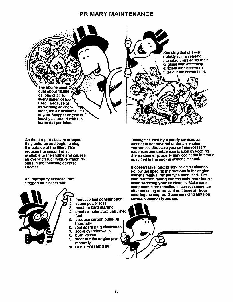
gulp about 12,000gallons of air for
used. Because ofits working environ-ment, the air availableto your Snapper engine Is "heavily saturated with air-borne dirt particles.
I(nowing that dirt willquickly ruin an engine,manufacturers equip theirengines with extremelyefficient air cleaners tofilter out the harmful dirt.
As the dirt particles are stopped,they build up and begin to clogthe outside of the filter. Thisreduces the amount of airavailable to the engine and causesan over-rich fuel mixture which re-sults In the following adverseeffects:
An Improperly serviced, dirtclogged air cleaner will:
1. Increase fuel consumption2. cause power loss3. result In hard starting4. create smoke from unburned
fuel5. produce carbon build-up ;
Internally6. foul spark plug electrodes7. score cylinder walls8. burn valves9. wear out the engine pre-
maturely10. COST YOU MONEY!
Damage caused by a poorly serviced aircleaner is not covered under the enginewarranties. So, save yourself unnecessaryexpenses and undue aggravation by keepingthe air cleaner properly serviced at the Intervalsspecified In the engine owner's manual.
It doesn't take long to service an air cleaner.Follow the specific instructions In the engineowner's manual for the type filter used. Pre-vent dirt from falling Into the carburetor Intakewhen ssrvicing your air cleaner• Make surecomponents are Installed In correct sequenceafter ssrvicing to prevent unfiltered air fromentering the engine. Some servicing hints onseveral common types are:
12

PRIMARY MAINTENANCE
Generally, wash foam-type filtersIn a dishwashlng detergent andwater solution. Rinse and wringdry, then saturate with oil andsqueeze out excess. Failure tore-oil this type filter will ruin theengine.
Clean paper elements by tappinglightly. Blowing with air willrupture paper elements.
Use a flashlight to detect cloggedor torn paper elements - replace Ifdamaged in any way.
Air is also needed to keepyour engine cool. Dirt, dust& debris build up to restrictand clog cooling air Intakescreens and fins. Cleanscreens and fins at frequentIntervals. The engine blowerhousing and shrouds shouldbe removed at least onceeach season or more oftenunder dry, dusty conditionsfor a thorough cleaning offins.
Failure to keep externalsurfaces clean not onlypresents fire hazards, but
causes overheating andresulting engine damagessuch as:
1. distorted valve guides2. sticking valves
° o. 3. scuffed, scored.,,_. walls
4. overspeedlng5. loss of power6. complete failure of
engine.
Dirt can also be IntroducedInto an engine In dirty fuelfrom a contaminatedcontainer. Always use cleanfresh fuel from a cleancontainer to guard againstdirt, sludge and watercontamination.
Be aware that fuel breaksdown in storage and formsgummy compounds whichwill block carburetor pass-ages. Never use fuel morethan 3 months old. Draintank then run the engine outof fuel before storing duringthe off-season.
An engine must also have proper lubrication.All englnes use some oli. On 4-cycle englnes,CHECK OIL LEVEL BEFORE EACH START-UP.Wlpe area clean around the oli check plug ordlpstlck opening to keep dlrt from falllng Intothe englne when checklng the oli. Alwayscheck wlth the machlne on a level surface.On englnes wlth dlpstlck, keep the level up to,but not over, the FULL mark. When addlng oli,allow tlme for all of the oli to flow down the filltube to prevent a false full readlng when thelevel could actually be low and result In englnedamage.
13

PRIMARY MAINTENANCE
On 4-cyle engines with an oll level plug,don't be fooled into thinking the engine hassufficient lubricating oil if you can see "some"oil in the opening - the level should always bebrought up to the point of at thetop of the fill hole.
I
On 2-cycle englnse, lubrication must beprovided by an exact mixture of gasolineand 2-cycle air-cooled engine oil. A 2-cycleengine that Is mistakenly run on straightgasoline will be ruined in less than 5mlnutesl If you keep straight gasoline inaddition to pre-mixed 2-cycle engine fuel,be sure the containers are clearly markedto avoid mix-up.Snapper 2-cycle engines require a 32 to 1mixture of gasoline and BIA certified TC-Woll such as Snapper's 2-cycle engine oil.Many of the 2-cycle engine oils on themarket today make fantastic claims, but forthe best performance and long engine life,always use Snapper 2-cycle oil Pre-mixthe fuel and always shake the containerbefore filling the tank.
Change oil at regular Intervals using a a highquality oil such as Snapper's small engineformulated 4-cycle engine oil Refer to theengine owner's manual for oll details.
STARTING CHECK UST
1. Engine Oil
2. Air Cleaner
3. Fuel Tank
4. Choke
5. Primer (onsome engines)
6. Safety Inter-lock Switches
7. Switch &
Blade Control
8. Spark plug
g. Throttlecontrol
10. Blade
11. Muffler
• To full level (4-cycle)• Properly mixed with gas
(2 cycle)• Clean and properly serviced• Full fresh clean gasoline• Fuel valve open• Cap vent open• Inline filter clean
• Operating properly• Used properly
• In proper position• All wires properly connected• Switch On
• Blade control properlypositioned on walk mower
• Wire connected• Good connection
• Start position
• Properly Installed andtorqued
• Sharpened• Good condition
• Not clogged• Grass & leaves cleaned away
Read and follow all safetyInstructions in safety book. Ilets and manuals. )
Keep in mind that dirt Is your engine's enemy#1 both Internally and externallyl Internally,dirt will quickly ruin an engine and externallyIt will cause overheating and resulting Internal
Damage caused by Improper lubrl-poor air cleaner service or overhesting
due to dirt cannot be covered under warranty.It only takes a few moments to service theengine (and equipment) on a routine basisbut the rewards will be a quick starting, re-sponsive engine that will provide longsatisfactory service with minimum maintenancecost. The prestart checklist In the next columnand Instructions In your Snapper Operator'sManual are designated to help you keep yourSnapper In top operating condition withminimum effortf
I i ii i
14

SERVICE NOTES
15

SERVICE NOTES
16

SERVICE NOTES
17

Safety Instructions & Operator's Manual for
INTERMEDIATEREAR TINE TILLERSERIES 4
®
I_L WARNING: The engine exhaust from this product contains chemicals known to the State Iof California to cause cancer, birth defects or other reproductive harm. I
SNAPPERMcDonough,GA., 30253 U.S.A.
COPYRIGHT © 1999SNAPPER INC.ALL RIGHTS RESERVED
18
MANUAL No. 7-2130 (REV. 1, 4/30/99)