Embed Size (px)
Citation preview

XA003T/02/a3/09.05
60019039
Safety instructions
RTD / TC Thermometer
Omnigrad TRxx, TCxx, TSTxxx, TxCxxx
Omniset TPR100, TET10x, TPC100, TECxxx
ATEX II 1GD or II 1/2GD EEx ia IIC T6...T1
0 ;
<
=
?
>
@
A
B
C
D
E
Sicherheitshinweise für elektrische Betriebsmittel für explosionsgefährdete Bereiche.
Safety instructions for electrical apparatus certified for use in explosion-hazardous areas.
Conseils de sécurité pour matériels électriquesdestinés aux zones explosibles.
Istruzioni di sicurezza per apparecchiature elettriche certificate per l'utilizzo in aree con pericolo di esplosione. Se il presente manuale non risulta com-prensibile potete ordinarcene una copia tradotta nella vostra lingua.
Instrucciones de seguridad de aparatos eléctricos homologados para su utili-zación en áreas expuestas a riesgos de deflagración. Si no entiende este manual, puede pedir un ejemplar en su idioma.
Veiligheidsinstructies voor elektrisch materieel in explosiegevaarlijke omge-ving. Wanneer u deze handleiding niet kunt lezen, kunt u een in uw landstaal vertaalde handleiding bij ons bestellen.
Turvallisuusohjeita sähkölaitteille, jotka on vahvistettu käytettäväksi räjäh-dysvaarallisilla alueilla. Jos et ymmärrä tätä käsikirjaa, voit tilata meiltä käännöksen omalla kansallisella kielelläsi.
Säkerhetsföreskrifter för elektrisk utrustning certifierad för användning i explosionsfarliga områden. Om du inte förstår denna manual, kan en översatt kopia på ditt eget språk beställas från oss.
Sikkerhedsforskrifter for elektriske apparater certificeret til brug i eksplosi-onsfarlige områder. Hvis du ikke forstår denne manual, kan en oversat kopi af den på dit eget sprog bestilles fra os.
Instruções de segurança para dispositivos eléctricos certificados para utiliza-ção em áreas de risco de incêndio. Se não compreender este manual, pode encomendar-nos directamente uma cópia na sua língua.
O o o
o μ o . μ
μ , μ
μ μ μ
.

Omnigrad, Omniset RTD/TC Thermometer
2 Endress+Hauser
Omnigrad, Omniset RTD/TC Thermometer
Endress+Hauser 3
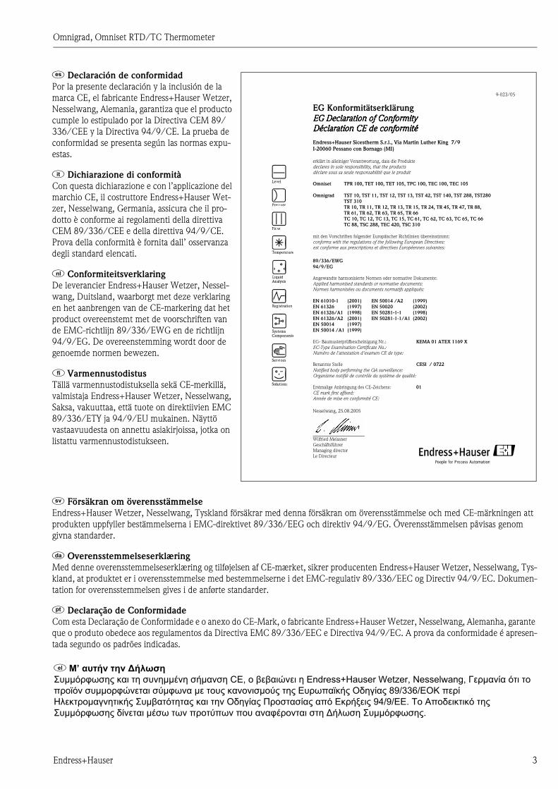
> Declaración de conformidad
Por la presente declaración y la inclusión de la
marca CE, el fabricante Endress+Hauser Wetzer,
Nesselwang, Alemania, garantiza que el producto
cumple lo estipulado por la Directiva CEM 89/
336/CEE y la Directiva 94/9/CE. La prueba de
conformidad se presenta según las normas expu-
estas.
? Dichiarazione di conformità
Con questa dichiarazione e con l’applicazione del
marchio CE, il costruttore Endress+Hauser Wet-
zer, Nesselwang, Germania, assicura che il pro-
dotto è conforme ai regolamenti della direttiva
CEM 89/336/CEE e della direttiva 94/9/CE.
Prova della conformità è fornita dall’ osservanza
degli standard elencati.
@ Conformiteitsverklaring
De leverancier Endress+Hauser Wetzer, Nessel-
wang, Duitsland, waarborgt met deze verklaring
en het aanbrengen van de CE-markering dat het
product overeenstemt met de voorschriften van
de EMC-richtlijn 89/336/EWG en de richtlijn
94/9/EG. De overeenstemming wordt door de
genoemde normen bewezen.
A Varmennustodistus
Tällä varmennustodistuksella sekä CE-merkillä,
valmistaja Endress+Hauser Wetzer, Nesselwang,
Saksa, vakuuttaa, että tuote on direktiivien EMC
89/336/ETY ja 94/9/EU mukainen. Näyttö
vastaavuudesta on annettu asiakirjoissa, jotka on
listattu varmennustodistukseen.
B Försäkran om överensstämmelse
Endress+Hauser Wetzer, Nesselwang, Tyskland försäkrar med denna försäkran om överensstämmelse och med CE-märkningen att
produkten uppfyller bestämmelserna i EMC-direktivet 89/336/EEG och direktiv 94/9/EG. Överensstämmelsen påvisas genom
givna standarder.
C Overensstemmelseserklæring
Med denne overensstemmelseserklæring og tilføjelsen af CE-mærket, sikrer producenten Endress+Hauser Wetzer, Nesselwang, Tys-
kland, at produktet er i overensstemmelse med bestemmelserne i det EMC-regulativ 89/336/EEC og Directiv 94/9/EC. Dokumen-
tation for overensstemmelsen gives i de anførte standarder.
D Declaração de Conformidade
Com esta Declaração de Conformidade e o anexo do CE-Mark, o fabricante Endress+Hauser Wetzer, Nesselwang, Alemanha, garante
que o produto obedece aos regulamentos da Directiva EMC 89/336/EEC e Directiva 94/9/EC. A prova da conformidade é apresen-
tada segundo os padrões indicadas.
EG Konformitätserklärung EG EG EGEG Declaration of ConformityDeclaration of ConformityDeclaration of ConformityDeclaration of Conformity Déclaration CE de conformitéDéclaration CE de conformitéDéclaration CE de conformitéDéclaration CE de conformité
Endress+Hauser Sicestherm S.r.l., Via Martin Luther King 7/9 I-20060 Pessano con Bornago (MI) erklärt in alleiniger Verantwortung, dass die Produkte declares in sole responsibility, that the products déclare sous sa seule responsabilité que le produit Omniset TPR 100, TET 100, TET 105, TPC 100, TEC 100, TEC 105 Omnigrad TST 10, TST 11, TST 12, TST 13, TST 42, TST 140, TST 288, TST280 TST 310 TR 10, TR 11, TR 12, TR 13, TR 15, TR 24, TR 45, TR 47, TR 88, TR 61, TR 62, TR 63, TR 65, TR 66 TC 10, TC 12, TC 13, TC 15, TC 61, TC 62, TC 63, TC 65, TC 66 TC 88, TSC 288, TEC 420, TSC 310 mit den Vorschriften folgender Europäischer Richtlinien übereinstimmt: conforms with the regulations of the following European Directives: est conforme aux prescriptions et directives Européennes suivantes:
89/336/EWG 94/9/EG Angewandte harmonisierte Normen oder normative Dokumente: Applied harmonised standards or normative documents: Normes harmonisées ou documents normatifs appliqués:
EN 61010-1 (2001) EN 50014 /A2 (1999) EN 61326 (1997) EN 50020 (2002) EN 61326/A1 (1998) EN 50281-1-1 (1998) EN 61326/A2 (2001) EN 50281-1-1/A1 (2002) EN 50014 (1997) EN 50014 /A1 (1999) EG- Baumusterprüfbescheinigung Nr.: KEMA 01 ATEX 1169 X EC-Type Examination Certificate No.: Numéro de l'attestation d'examen CE de type: Benannte Stelle CESI / 0722 Notified body performing the QA surveillance: Organisme notifié de contrôle du système de qualité:
Erstmalige Anbringung des CE-Zeichens: 01 CE mark first affixed: Année de mise en conformité CE:
Nesselwang, 25.08.2005
Wilfried Meissner Geschäftsführer Managing director Le Directeur
9-023/05
E M’
μμ μμ μ CE, o Endress+Hauser Wetzer, Nesselwang, μ o
o μμo μ μ o o μo E O 89/336/EOK
H oμ μ O o E 94/9/EE. o A o
μμ μ o o o μμ .

Omnigrad, Omniset RTD/TC Thermometer
4 Endress+Hauser

Omnigrad, Omniset RTD/TC Thermometer Sicherheitshinweise
Endress+Hauser 5
Sicherheitshinweise
Omnigrad, Omniset
RTD/TC Thermometer
für elektrische Betriebsmittel für explosionsgefährdete Bereiche
Einsatzbereiche:
0 Kennzeichnung nach Richtlinie 94/9/EG: 4 0 II 1 oder 1/2 GD T85...450°C
Gerätegruppe II
Gerätekategorie: 1
oder Sensor Kategorie 1 /
Gehäuse Kategorie 2
Für explosionsfähige Gemische aus Luft und
brennbaren Stäuben, Gasen, Dämpfen oder
Nebeln
Maximale Oberflächentemperatur bei maximal
zulässiger Umgebungstemperatur
Gerätekategorie Explosionsfähige Gas-Luft-Gemische (G) Explosionsfähige Staub-Luft-Gemische (D)
Kategorie 1 Zone 0, 1 oder 2 Zone 20, 21 oder 22
Kategorie 2 Zone 1 oder 2 Zone 21 oder 22
Kategorie 3 Zone 2 Zone 22
Kennzeichnung der Schutzart: EEx ia IIC T6...T1
Explosionsgeschütztes elektrisches Betriebsmittel
nach Europanorm
Zündschutzart
Betriebsmittelgruppe
Temperaturklasse
XA003T/02/a3
60019039
II 1GD or II 1/2GD

Sicherheitshinweise Omnigrad, Omniset RTD/TC Thermometer
6 Endress+Hauser
Einführung
Die Widerstandsthermometer Omnigrad vom Typ TSTxx, TSTxxx und TRxx sind mit den Messein-
sätzen Omniset TET10x bzw. TPR100, die Thermoelement-Thermometer Omnigrad vom Typ
TxCxxx und TCxx sind mit den Messeinsätzen Omniset TEC10x bzw. TPC100 ausgestattet, und
können in explosionsgefährdeten Bereichen eingesetzt werden, die als Zone 0, 1 bzw. 2 (bei Gegen-
wart von Gas) und Zone 20, 21 bzw. 22 (bei Gegenwart von Staub) eingestuft sind. Je nach Appli-
kation kann die Versorgung der Messeinsätze entweder durch ein zugehöriges Betriebsmittel, einen
eigensicheren Temperaturtransmitter oder einen eigensicheren Endress+Hauser Kopftransmitter
nach Tabelle 1 erfolgen.
Allgemeine Installationshinweise
Der Einbau und die Wartung der Geräte müssen in Übereinstimmung mit den Anweisungen des
Herstellers und den entsprechend gültigen Normen und Vorschriften (zum Beispiel EN 60079-14,
EN 50281-1-2 oder anderen nationalen Normen und Vorschriften) erfolgen.
Installationshinweise für Staub-explosionsgefährdete Bereiche
• Errichtung und Instandhaltung gemäß Herstellerangaben und gültigen Normen und Regeln (z.B.
EN 50281-1-2)
• Kabel- und Leitungseinführungen müssen so ausgeführt sein, dass sie die geforderte Gehäuse-
schutzart der jeweiligen Kategorie einhalten und den Anforderungen nach EN 50014 genügen.
• Bei Umgebungstemperaturen größer als 70°C müssen geeignete Kabel, Leitungen oder Leiter für
Rohrleitungen verwendet werden.
• Vermeidung einer übermäßigen Bildung von Staubschichten (größer 5 mm) auf dem Gehäuse
durch regelmäßige Reinigung.
• Die Gehäuse sind an die Potenzialausgleichsleitung anzuschließen, oder müssen in einem geer-
deten metallischen Rohrleitungssystem bzw. Behälter eingebaut sein.
• Die Schweißung kann durch WIG -, Laserschweißen oder vergleichbare Verfahren erfolgen,
wobei die innere Struktur der Messeinsätze nicht durch die Schweißarbeiten an der äußeren
Oberfläche verändert werden darf.
• Verwendung von standardisierten Klemmverschraubungen nach DIN, ISO.
• Bei Verwendung einer Steckverbindung (z.B. PA-Stecker von Weidmüller) ist darauf zu achten,
dass die Anforderungen für die jeweilige Kategorie und seine Betriebstemperatur eingehalten
werden.
Sicherheitshinweise für die Zone 20 oder Zone 21:
Diese Anforderungen sind nur zu beachten, wenn das Gerät in Zone 20 bzw. Zone 21 (Kategorie 1
bzw. Kategorie 2) installiert wird.
• Bei der Errichtung und Instandhaltung des Thermometers ist darauf zu achten, dass auch in selten
und gelegentlich auftretenden Fällen eine Zündquelle durch Stoß oder Reibung zwischen Metall/
Stahl und dem Gehäuse ausgeschlossen ist.
Diese Anforderungen sind nur zu beachten bei der Verwendung von Thermometern, die nicht
denen in Tabelle 1 entsprechen (komplett von Endress+Hauser gelieferte Thermometer und die
dazu passenden Schutzrohre erfüllen diese Bedingungen):
Messeinsatz Widerstandsthermometer Temperaturkopftransmitter
TPR100
TET100
TET105
TST310
TR10, TR11, TR12, TR13, TR15, TR24, TR45, TR47, TR88,
TR61, TR62, TR63, TR65, TR66
TST10, TST11, TST12, TST13, TST42, TST140, TST288, TST280
TMT181
TMT182
TMT184
Messeinsatz Thermoelement Temperaturkopftransmitter
TPC100
TEC100
TEC105
TSC310
TC10, TC12, TC13, TC15, TC88, TSC288, TEC420
TC61, TC62, TC63, TC65, TC66
TMT181
TMT182
TMT184
Tabelle 1

Omnigrad, Omniset RTD/TC Thermometer Sicherheitshinweise
Endress+Hauser 7
• Bei Verwendung eines Gehäuses aus Leichtmetall darf nur ein Masseanteil von nicht mehr als 6%
Magnesium enthalten sein.
• Bei Verwendung von Kunststoffgehäusen muss der Werkstoff einen Oberflächenwiderstand klei-
ner 109 Ohm haben.
• Gehäuse aus nichtmetallischen Materialien müssen den Anforderungen nach EN 50281-1-1
(Punkt 4.2.3) entsprechen, deren Materialien keine elektrostatische Aufladung erzeugen dürfen.
• Es sind zugelassene Kabelverschraubungen und Dichtung für die jeweilige Kategorie zu verwen-
den, die den Anforderungen nach EN 50014 (Paragraph B 3.3) entsprechen.
Sicherheitshinweise für die Zone 20 oder Zone 21:
Diese Angaben sind nur zu beachten, wenn das Gerät in Zone 20 bzw. Zone 21 (Kategorie 1 bzw.
Kategorie 2) installiert wird.
• Beim Einbau des Geräts ist darauf zu achten, dass ein Gehäuse nach Kategorie 1D bzw. 2D, min-
destens mit einem Gehäuseschutzgrad IP 6x, verwendet wird.
Sicherheitshinweise für die Zone 22:
Diese Angaben sind nur zu beachten, wenn das Gerät in die Zone 22 (Kategorie 3) installiert wird.
• Beim Einbau des Geräts ist darauf zu achten, dass ein Gehäuse nach Kategorie 3D, mindestens
mit einem Gehäuseschutzgrad IP 54, verwendet wird.
Installationshinweise für Gas-explosionsgefährdete Bereiche
• Installieren Sie gemäß Herstellerangaben und für Sie gültigen Normen und Regeln.
• Beachten Sie die Sicherheitshinweise der verwendeten Transmitter.
• Beachten Sie die erlaubten Umgebungstemperaturen der verwendeten Transmitter in den jewei-
ligen Temperaturklassen.
• Beim Anschluss sind die Regeln für das Zusammenschalten eigensicherer Stromkreise zu beach-
ten.
• Beim Einbau des Gerätes ist darauf zu achten, dass die Gehäuseschutzart IP20 eingehalten wird.
• Die zulässige Umgebungstemperatur am Elektronikgehäuse darf den Bereich von -40...130°C
nicht überschreiten oder bei eingebautem Elektronikeinsatz darf die zulässige Umgebungstempe-
ratur des eingebauten Elektronikeinsatzes nicht überschritten werden.
• Bei dualen Messeinsätzen ist darauf zu achten, dass bei Anschluss an die Potenzialausgleichslei-
tung das gleiche Potenzial vorhanden ist.
• Die Messeinsätze mit 3 mm Durchmesser müssen an die Potenzialausgleichsleitung angeschlos-
sen werden.
• Bei Messeinsätzen mit 3 mm Durchmesser muss eine eigensichere Speisung mit galvanischer
Trennung verwendet werden.
Sicherheitshinweise für die Zone 0:
Diese Angaben sind nur zu beachten, wenn das Gerät direkt in die Zone 0 (Kategorie 1) installiert
wird.
• Einbau des Transmitters in einen geerdeten metallischen Kopf bzw. geerdetes Gehäuse.
• Explosionsfähige Dampf-/Luftgemische dürfen nur unter atmosphärischen Bedingungen auftre-
ten:
-20°C ≤ Ta ≤ +60°
0,8 bar ≤ p ≤ 1,1 bar
• Liegen keine explosionsfähigen Gemische vor oder sind Zusatzmaßnahmen gemäß EN1127-1
getroffen, dürfen die Geräte auch außerhalb der atmosphärischen Bedingungen gemäß ihrer Her-
stellerspezifikation betrieben werden.
• Bei der Errichtung und Instandhaltung des Thermometers ist darauf zu achten, dass auch in selten
und gelegentlich auftretenden Fällen eine Zündquelle durch Stoß oder Reibung zwischen Metall/
Stahl und dem Gehäuse ausgeschlossen ist.
• Bei der Errichtung und Instandhaltung des Thermometers ist darauf zu achten, dass eine elektro-
statische Aufladung der Kabel vermieden wird.
Diese Angabe ist nur gültig, wenn das Gerät in die Zonentrennwand (Kategorie 1 oder 1/2) instal-
liert wird:
• Bei Schutzniveau "ia" ist kein mechanisches Trennelement in Form eines Schutzrohrs oder eines
Gehäuses nach EN 50284 erforderlich.
Sicherheitshinweise Omnigrad, Omniset RTD/TC Thermometer
8 Endress+Hauser
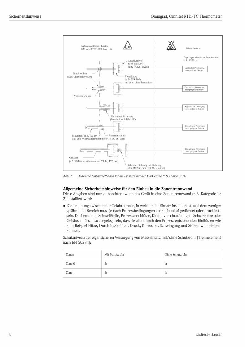
Abb. 1: Mögliche Einbaumethoden für die Einsätze mit der Markierung II 1GD bzw. II 1G
Allgemeine Sicherheitshinweise für den Einbau in die Zonentrennwand
Diese Angaben sind nur zu beachten, wenn das Gerät in eine Zonentrennwand (z.B. Kategorie 1/
2) installiert wird:
• Die Trennung zwischen der Gefahrenzone, in welcher der Einsatz installiert ist, und dem weniger
gefährdeten Bereich muss je nach Prozessbedingungen ausreichend abgedichtet oder druckfest
sein. Die benutzten Schweißteile, Prozessanschlüsse, Klemmverschraubungen, Schutzrohre oder
Gehäuse müssen so ausgelegt sein, dass sie allen durch den Prozess entstehenden Einflüssen wie
zum Beispiel Hitze, Durchflusskräften, Druck, Korrosion, Schwingung und Stößen widerstehen
können.
Schutzniveau der eigensicheren Versorgung von Messeinsatz mit/ohne Schutzrohr (Trennelement
nach EN 50284):
EX EX
Klemmverschraubung
Prozessanschluss
Prozessanschluss
(Standard nach DIN, ISO)
Einschweißen
(WIG -,Laserschweißen) Messeinsatz(z..B. TPR 100)mit oder ohne Transmitter
Gehäuse
Anschlusskopfnach EN 50014(z.B. TA20x, TA21E)
Explosionsgefährdeter BereichZone 0, 1, 2 oder Zone 20, 21, 22 Sicherer Bereich
Eigensichere Versorgungoder geeignete Barriere
Eigensichere Versorgungoder geeignete Barriere
Eigensichere Versorgungoder geeignete Barriere
Eigensichere Versorgungoder geeignete Barriere
Eigensichere Versorgungoder geeignete Barriere
Zugehöriges elektrisches Betriebsmittelz. B. RN 221N
(z.B. von Widerstandsthermometer TR 1x, TST xxx)
(z.B. Widerstandsthermometer TR 1x, TST xxx)
Schutzrohr (z.B. TW 10)
Kabeldurchführung mit Dichtungoder M12-Stecker (z.B. Weidmüller)
Zonen Mit Schutzrohr Ohne Schutzrohr
Zone 0 ib ia
Zone 1 ib ib
Omnigrad, Omniset RTD/TC Thermometer Sicherheitshinweise
Endress+Hauser 9
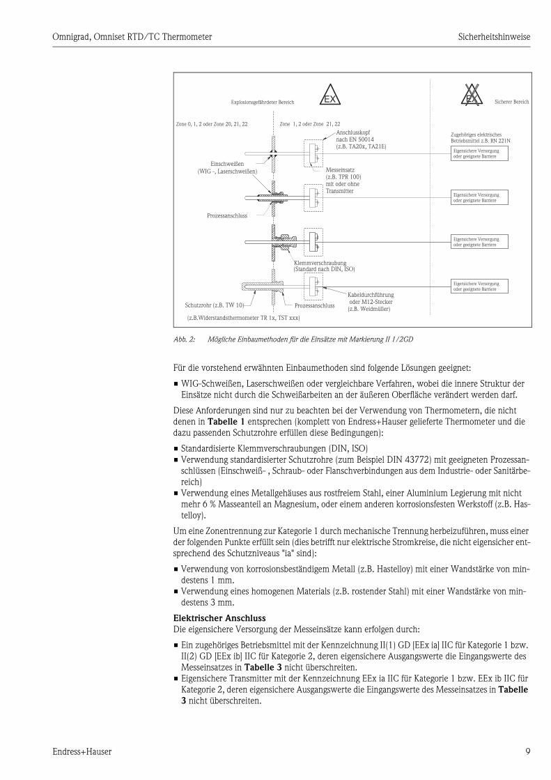
Abb. 2: Mögliche Einbaumethoden für die Einsätze mit Markierung II 1/2GD
Für die vorstehend erwähnten Einbaumethoden sind folgende Lösungen geeignet:
• WIG-Schweißen, Laserschweißen oder vergleichbare Verfahren, wobei die innere Struktur der
Einsätze nicht durch die Schweißarbeiten an der äußeren Oberfläche verändert werden darf.
Diese Anforderungen sind nur zu beachten bei der Verwendung von Thermometern, die nicht
denen in Tabelle 1 entsprechen (komplett von Endress+Hauser gelieferte Thermometer und die
dazu passenden Schutzrohre erfüllen diese Bedingungen):
• Standardisierte Klemmverschraubungen (DIN, ISO)
• Verwendung standardisierter Schutzrohre (zum Beispiel DIN 43772) mit geeigneten Prozessan-
schlüssen (Einschweiß- , Schraub- oder Flanschverbindungen aus dem Industrie- oder Sanitärbe-
reich)
• Verwendung eines Metallgehäuses aus rostfreiem Stahl, einer Aluminium Legierung mit nicht
mehr 6 % Masseanteil an Magnesium, oder einem anderen korrosionsfesten Werkstoff (z.B. Has-
telloy).
Um eine Zonentrennung zur Kategorie 1 durch mechanische Trennung herbeizuführen, muss einer
der folgenden Punkte erfüllt sein (dies betrifft nur elektrische Stromkreise, die nicht eigensicher ent-
sprechend des Schutzniveaus "ia" sind):
• Verwendung von korrosionsbeständigem Metall (z.B. Hastelloy) mit einer Wandstärke von min-
destens 1 mm.
• Verwendung eines homogenen Materials (z.B. rostender Stahl) mit einer Wandstärke von min-
destens 3 mm.
Elektrischer Anschluss
Die eigensichere Versorgung der Messeinsätze kann erfolgen durch:
• Ein zugehöriges Betriebsmittel mit der Kennzeichnung II(1) GD [EEx ia] IIC für Kategorie 1 bzw.
II(2) GD [EEx ib] IIC für Kategorie 2, deren eigensichere Ausgangswerte die Eingangswerte des
Messeinsatzes in Tabelle 3 nicht überschreiten.
• Eigensichere Transmitter mit der Kennzeichnung EEx ia IIC für Kategorie 1 bzw. EEx ib IIC für
Kategorie 2, deren eigensichere Ausgangswerte die Eingangswerte des Messeinsatzes in Tabelle
3 nicht überschreiten.
EX EX
Schutzrohr (z.B. TW 10)
Klemmverschraubung
Prozessanschluss
Prozessanschluss
Messeinsatz(z.B. TPR 100)mit oder ohneTransmitter
Explosionsgefährdeter Bereich Sicherer Bereich
Eigensichere Versorgungoder geeignete Barriere
Eigensichere Versorgungoder geeignete Barriere
Eigensichere Versorgungoder geeignete Barriere
Eigensichere Versorgungoder geeignete Barriere
Zugehöriges elektrischesBetriebsmittel z.B. RN 221N
Zone 0, 1, 2 oder Zone 20, 21, 22 Zone 1, 2 oder Zone 21, 22
(z.B.Widerstandsthermometer TR 1x, TST xxx)
Einschweißen
(WIG -, Laserschweißen)
(Standard nach DIN, ISO)
Anschlusskopfnach EN 50014(z.B. TA20x, TA21E)
Kabeldurchführungoder M12-Stecker
(z.B. Weidmüller)

Sicherheitshinweise Omnigrad, Omniset RTD/TC Thermometer
10 Endress+Hauser
• Zertifizierte Transmitter (z.B. TMT12x), die nicht in Tabelle 2 aufgeführt sind. Hierbei und bei
zugehörigen Betriebsmitteln ist darauf zu achten, dass deren eigensichere Ausgangswerte (Uo, Io,
Po, Lo und Co) die Eingangswerte (Ui, Ii, Pi, Li und Ci) der Messeinsätze in Tabelle 3 nicht über-
schreiten.
• ATEX zertifizierte Kopftransmitter TMT181, TMT182 oder TMT184, deren eigensichere Ein-
gangswerte in Tabelle 2 aufgeführt sind.
! Hinweis!
Bei dualen Einsätzen dürfen zwei eigensichere Stromkreise in 2- bzw. 3- Leiter (z.B. 2 x Pt100 3-
Leiter) Schaltung angeschlossen werden. Dabei ist zu beachten, dass Spannung und Strom addiert
werden müssen. Die Summe der angelegten Spannungen und Ströme darf die Werte in Tabelle 3
nicht überschreiten.
Die eigensicheren Eingangsleistungen sind ebenso bestimmend wie die erlaubten Umgebungstem-
peraturen bzw. Prozesstemperaturen in den jeweiligen Temperaturklassen:
• Die Temperaturklassen des verwendeten Transmitters bestimmen den Einsatzbereich in den
Temperaturklassen. (Bsp. Bei Verwendung eines Transmitters mit max. T4 kann das Widerstand-
thermometer bzw. der Messeinsatz auch nur bis T4 verwendet werden.)
• Bei zertifizierten Transmittern, deren eigensichere Ausgangswerte nicht definiert sind, gelten die
maximalen Prozesstemperaturen in Tabelle 5 in Abhängigkeit zu ihrer maximal angegebenen
eigensicheren Eingangsleistung.
• Bei zugehörigen Betriebsmittel oder eigensicheren Kopftransmittern, bei denen die eigensicheren
Ausgangswerte definiert sind, gelten die Prozesstemperaturen in Tabelle 4 in Abhängigkeit zur
maximal angegebenen eigensicheren Eingangsleistung der Messeinsätze.
• Für die Thermometer TRxx, TSTxx, TSTxxx, TxCxxx, TCxx, die einen nach ATEX zertifizierten
Endress+Hauser Kopftransmitter TMT181, TMT182 oder TMT184 beinhalten, sind die maximal
erlaubten Prozesstemperaturen in Tabelle 4 der Spalte Pi ≤ 50 mW (Eingangsleistung am Mes-
seinsatz) gültig.
In der folgenden Tabelle sind die maximalen Eingangswerte der Endress+Hauser Kopftransmitter
dargestellt:
In der folgenden Tabelle sind die maximalen Eingangswerte der Endress+Hauser Messeinsätze dar-
gestellt:
Kopftransmitter Eigensichere Eingangswerte
Ui li Pi
TMT181 30 V 100 mA 750 mW
TMT182 30 V 100 mA 750 mW
TMT184 17,5 V 500 mA 5,5 W
Tabelle 2
Messeinsatz Eigensichere Eingangswerte
Ui li Pi Ci Li
TPR100 30 V 100 mA 750 mW ≤ 1 nF ≤ 1 mH
TET100 30 V 100 mA 750 mW
TET105 30 V 100 mA 750 mW

Omnigrad, Omniset RTD/TC Thermometer Sicherheitshinweise
Endress+Hauser 11
TPC100 30 V 100 mA 750 mW ≤ 1 nF ≤ 1 mH
TEC100 30 V 100 mA 750 mW
TEC105 30 V 100 mA 750 mW
TSC310 30 V 100 mA 750 mW ≤ 1 nF ≤ 1 mH
TST310 30 V 100 mA 750 mW
Tabelle 3
Messeinsatz Eigensichere Eingangswerte
Messeinsatz
Durchmesser
Staub- explosi-
onsgefährdete
Atmosphäre
Gas- explosions-
gefährdete
Atmosphäre
Pi ≤ 50 mW Pi ≤ 100 mW Pi ≤ 200 mW Pi ≤ 500 mW
Maximale Oberflä-
chentemperatur T
(°C)
Temperaturklasse Maximal erlaubte Prozess- Temperaturen (°C)
3 mm,
3 mm (dual)
oder 6 mm dual
450 T1 426 415 396 343
300 T2 276 265 246 193
200 T3 181 170 151 98
135 T4 116 105 86 33
100 T5 81 70 51 -2
85 T6 66 55 36 -17
6 mm 450 T1 433 428 420 398
300 T2 283 278 270 248
200 T3 188 183 175 153
135 T4 123 118 110 88
100 T5 88 83 75 53
85 T6 73 68 60 38
Tabelle 4

Sicherheitshinweise Omnigrad, Omniset RTD/TC Thermometer
12 Endress+Hauser
Messeinsatz Durchmes-
ser
Staub- explosionsgefähr-
dete Atmosphäre
Gas- explosionsgefähr-
dete Atmosphäre
Pi ≤ 650 mW Pi ≤ 750 mW
Maximale Oberflächentem-
peratur T (°C)
Temperaturklasse Maximal erlaubte Prozess- Temperaturen (°C)
3 mm,
3 mm (dual)
oder 6 mm dual
450 T1 333 320
300 T2 183 170
200 T3 88 75
135 T4 23 10
100 T5 -12 -25
85 T6 -27 -40
6 mm 450 T1 388 381
300 T2 238 231
200 T3 143 136
135 T4 78 71
100 T5 43 36
85 T6 28 21
Tabelle 5

Omnigrad, Omniset RTD/TC Thermometer Safety instructions
Endress+Hauser 13
Safety instructions
Omnigrad, Omniset
RTD/TC Thermometer
for electrical apparatus certified for use in explosion-hazardous areas
Areas of application:
0 Designation according to Directive 94/9/EG: 4 0 II 1 or 1/2 GD T85...450°C
Equipment Group II
Equipment Category 1
or Sensor Category 1 /
Housing Category 2
For explosive mixtures of air and combustible
gases, dust, vapours or mists
Maximum surface temperature at maximum
ambient temperature
Equipment Category Explosive gas-air mixtures (G) Explosive dust-air mixtures (D)
Category 1 Zone 0, 1 or 2 Zone 20, 21 or 22
Category 2 Zone 1 or 2 Zone 21 or 22
Category 3 Zone 2 Zone 22
Designation of explosion protection: EEx ia IIC T6...T1
Electrical apparatus with explosion protection to
European standard
Type of protection
Apparatus group
Temperature class
XA003T/02/a3
60019039
II 1GD or II 1/2GD

Safety instructions Omnigrad, Omniset RTD/TC Thermometer
14 Endress+Hauser
Introduction
The RTD thermometer Omnigrad series TSTxx, TSTxxx and TRxx are equipped with the inserts
TET10x resp. TPR100; The thermocouple thermometer Omnigrad series TCxx and TxCxxx are
equipped with the inserts TSC10x resp. TPC100. They can be used in hazardous areas, which are
classified as Zone 0, 1 resp. Zone 2 for gas atmosphere and/or Zone 20, 21 resp. 22 for dust
atmosphere. Depending on application the supply of inserts can be realized either by an Associated
Intrinsical Supply, an intrinsically safe temperature transmitter or an Endress+Hauser head
transmitter according to table 1.
General notes of installation
The installation and maintenance of the units must be carried out complying with the
manufacturer's instructions and with the valid standards/regulations (for example EN 60079-14,
EN 50281-1-2 or other national standards and regulations).
Installation notes for dust hazardous areas
• Installation and maintenance according to manufacturer's instructions and valid standards and
regulations (e.g. EN 50281-1-2)
• Cable and cable glands are to be realized in a way that the degree of ingress protection complies
with the requirements of the respective category and the standard EN 50014.
• For ambient temperatures higher than 70 °C, suitable cables, pipes or conductors must be used
for installation.
• Avoiding an undue formation of layer greater 5 mm through a regular cleaning of the housing.
• The housing is to be connected to a potential matching line or installed in a metallic piping or tank
respectively.
• The welding may be carried out by means of TIG welding, laser welding or equivalent ones; the
internal structure of the insert has not to be altered by the welding.
• Using of standardized compression fittings (DIN, ISO)
• For using of a plug-in connector (e.g. PA- connector by Weidmüller) is to be observed that the
requirements for the respective category and the operating temperature are followed.
Safety notes for zone 20 or zone 21:
These requirements are only to be followed if the unit is installed in zone 20 or zone 21 (category
1 or category 2).
• The thermometer must be installed and maintained so, that even in the event of rare incidents,
an ignition source due to impact or friction between the enclosure and iron/steel is excluded.
These requirements are only to be followed for using thermometer, which are not listed in table 1.
(Completely delivered Endress+Hauser thermometers and suitable thermowells fulfill these
requirements.)
• For using a light metal housing, the material must not contain more than mass portion of 6%
magnesium.
• For using of plastic housings their surface resistance of material must be smaller than 109 Ohm.
Insert RTD thermometer Head transmitter
TPR100
TET100
TET105
TST310
TR10, TR11, TR12, TR13, TR15, TR24, TR45, TR47, TR88,
TR61, TR62, TR63, TR65, TR66
TST10, TST11, TST12, TST13, TST42, TST140, TST288, TST280
TMT181
TMT182
TMT184
Insert Thermocouple Head transmitter
TPC100
TEC100
TEC105
TSC310
TC10, TC12, TC13, TC15, TC88, TSC288, TEC420
TC61, TC62, TC63, TC65, TC66
TMT181
TMT182
TMT184
Table 1

Omnigrad, Omniset RTD/TC Thermometer Safety instructions
Endress+Hauser 15
• Housings out of non-metallic materials have to comply with the requirements to EN 50281-1-1
(clause 4.2.3) and may not cause any electrostatic charge.
• Approved cable glands and sealings are to be used for the respective category according to the
requirements of standard EN 50014 (paragraph B.3.3).
Safety notes for Zone 20 or Zone 21:
These requirements are only to be followed if the unit is installed in zone 20 or zone 21 (category
1 or category 2) .
• When installing the device, ensure that a housing in accordance with category 1D resp. 2D with
a degree of ingress protection of at least IP6X is used.
Safety notes for Zone 22:
These requirements are only to be followed if the unit is installed in zone 22 (category 3).
• When installing the device, ensure that a housing in accordance with category 3D with a degree
of ingress protection of at least IP54 is used.
Installation notes for gas hazardous area
• Install the device according to the manufacturer's instructions and any other valid standards and
regulations.
• Observe the safety instructions for the used transmitters.
• Observe the permitted ambient temperatures of the used transmitters for the respective
temperature classification.
• For connection the rules for interconnecting intrinsically safe circuits are to be observed.
• When installing the unit note that the housing degree of ingress protection IP 20 is upheld.
• The permissible ambient temperature at the electronic housing may not exceed the range of -
40…130°C or the permissible ambient temperature of the mounted electronic may not exceed.
• For dual inserts is to be observe that for the connection to the potential matching line the same
potential is given.
• The inserts with 3 mm diameter are to be connected to the potential matching line.
• For the inserts with 3 mm diameter an intrinsical safe supply with galvanic isolation must be used.
Safety instructions for Zone 0:
• These instructions are only valid if the unit is to be installed directly in the Zone 0 (Category 1).
• Explosive moisture/air mixtures are only allowed to occur under atmospheric conditions
-20°C ≤ Ta ≤ +60°
0.8 bar ≤ p ≤ 1.1bar
• If there is no explosive mixture present or the additional measures according to EN 1127-1 is
upheld the unit can also be operated outside the atmospheric conditions according to the
manufacturer's specification.
• The thermometer must be installed and maintained so, that even in the event of rare incidents,
an ignition source due to impact or friction between the enclosure and iron/steel is excluded.
• When installing and maintaining the Thermometer note, that the electrostatic charging of cable
is to be avoided.
This statement is only valid if the device is installed in the zone partition (category 1 or 1/2):
For protection level "ia" no mechanical partition in terms of thermowell or enclosure is necessary
according to EN 50284.

Safety instructions Omnigrad, Omniset RTD/TC Thermometer
16 Endress+Hauser
Fig. 3: Possible methods with marking II1GD or II1G
General safety notes for the installation in partition
These statements are only valid if the device is installed in the zone partition (category 1/2):
• The separation between the hazardous area in which the insert is positioned, and the external less
hazardous area must be sufficiently tight or flameproof.
• The used weldings, process connection, compression fitting, thermowell or enclosure must be
designed to withstand the possible effects due to environmental conditions, as example heat,
fluid-dynamic forces, pressure, corrosion, vibration and shocks coming from the process actions.
Protection level of the intrinsically safe supply of insert with or without thermowell (partition
according to EN 50284):
EX EX
Compression fitting
Process connection
Process connection
(Standard to DIN, ISO)
Welding
(TIG -, laser welding) Insert(e.g. TPR 100)with or without transmitter
Thermometer
mounting headto EN 50014(e.g. TA20x, TA21E)
Hazardous areaZone 0, 1, 2 or Zone 20, 21, 22 Non hazardous area
Intrinsically safe power supplyor suitable barrier
Intrinsically safe power supplyor suitable barrier
Intrinsically safe power supplyor suitable barrier
Intrinsically safe power supplyor suitable barrier
Intrinsically safe power supplyor suitable barrier
Associated intrinsically safepower supplye.g. RN 221N
(e.g. from RTD thermometer TR 1x, TST xxx)
(e.g. RTD thermometer TR 1x, TST xxx)
thermowell (e.g. TW 10)
Cable gland with sealingor M12 connector (e.g. by Weidmüller)
Zone with thermowell without thermowell
Zone 0 ib ia
Zone 1 ib ib
Omnigrad, Omniset RTD/TC Thermometer Safety instructions
Endress+Hauser 17
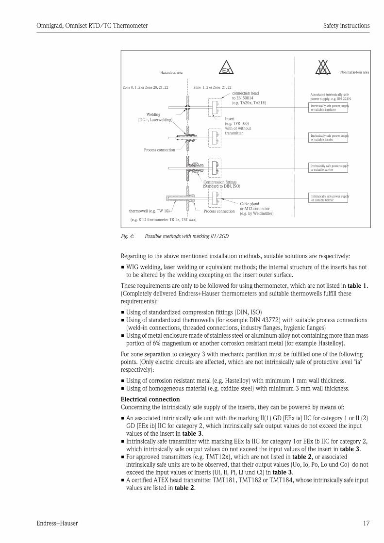
Fig. 4: Possible methods with marking II1/2GD
Regarding to the above mentioned installation methods, suitable solutions are respectively:
• WIG welding, laser welding or equivalent methods; the internal structure of the inserts has not
to be altered by the welding excepting on the insert outer surface.
These requirements are only to be followed for using thermometer, which are not listed in table 1.
(Completely delivered Endress+Hauser thermometers and suitable thermowells fulfill these
requirements):
• Using of standardized compression fittings (DIN, ISO)
• Using of standardized thermowells (for example DIN 43772) with suitable process connections
(weld-in connections, threaded connections, industry flanges, hygienic flanges)
• Using of metal enclosure made of stainless steel or aluminum alloy not containing more than mass
portion of 6% magnesium or another corrosion resistant metal (for example Hastelloy).
For zone separation to category 3 with mechanic partition must be fulfilled one of the following
points. (Only electric circuits are affected, which are not intrinsically safe of protective level "ia"
respectively):
• Using of corrosion resistant metal (e.g. Hastelloy) with minimum 1 mm wall thickness.
• Using of homogeneous material (e.g. oxidize steel) with minimum 3 mm wall thickness.
Electrical connection
Concerning the intrinsically safe supply of the inserts, they can be powered by means of:
• An associated intrinsically safe unit with the marking II(1) GD [EEx ia] IIC for category 1 or II (2)
GD [EEx ib] IIC for category 2, which intrinsically safe output values do not exceed the input
values of the insert in table 3.
• Intrinsically safe transmitter with marking EEx ia IIC for category 1or EEx ib IIC for category 2,
which intrinsically safe output values do not exceed the input values of the insert in table 3.
• For approved transmitters (e.g. TMT12x), which are not listed in table 2, or associated
intrinsically safe units are to be observed, that their output values (Uo, Io, Po, Lo und Co) do not
exceed the input values of inserts (Ui, Ii, Pi, Li und Ci) in table 3.
• A certified ATEX head transmitter TMT181, TMT182 or TMT184, whose intrinsically safe input
values are listed in table 2.
EX EX
thermowell (e.g. TW 10)
Compression fittings
Process connection
Process connection
Insert(e.g. TPR 100)with or withouttransmitter
Hazardous area Non hazardous area
Intrinsically safe power supplyor suitable barrier
Intrinsically safe power supplyor suitable barrierer
Intrinsically safe power supplyor suitable barrier
Intrinsically safe power supplyor suitable barrier
Associated intrinsically safepower supply, e.g. RN 221N
Zone 0, 1, 2 or Zone 20, 21, 22 Zone 1, 2 or Zone 21, 22
(e.g. RTD thermometer TR 1x, TST xxx)
Welding
(TIG -, Laserwelding)
(Standard to DIN, ISO)
connection headto EN 50014(e.g. TA20x, TA21E)
Cable glandor M12 connector(e.g. by Weidmüller)

Safety instructions Omnigrad, Omniset RTD/TC Thermometer
18 Endress+Hauser
! Note!
For dual inserts it is allowed to connect two intrinsically safe circuits in 2- or 3-wire (e.g. 2 x Pt100
3-wire). Thereby notice that the voltage and current is to be added. The sum of the connected
voltages and currents must not exceed the values in table 3.
The intrinsically safe input powers are determining as well as the allowed ambient temperatures or
process temperatures in the respective temperature classes.
• The temperature classification of using transmitter defines the range of use in the temperature
classification (for example using of a transmitter with max. T4 the thermometer resp. insert can
only be used for T4).
• Certified transmitters, for which intrinsically safe output values are not defined, the maximum
process temperatures in table 5 are valid depending on the stated maximum intrinsically safe
input power.
• Associated intrinsically safe units or intrinsically safe head transmitter, for which intrinsically safe
output values are defined, the process temperatures in table 4 are valid depending on the stated
maximum intrinsically safe input power of the inserts.
• For thermometers (TRxx, TSTxx, TSTxxx, TxCxxx, TCxx), which are equipped with a certified
Endress+Hauser head transmitter TMT181, TMT182 or TMT184, the maximal allowed process
temperature in column Pi ≤ 50 mW of table 4 are valid.
In the following table the maximum connection values for the power supply of Endress+Hauser
head transmitter are listed:
In the following table the maximum input values of Endress+Hauser inserts are listed:
Head transmitter Intrinsically safe input values
Ui li Pi
TMT181 30 V 100 mA 750 mW
TMT182 30 V 100 mA 750 mW
TMT184 17,5 V 500 mA 5,5 W
Table 2
Insert Intrinsically safe input values
Ui li Pi Ci Li
TPR100 30 V 100 mA 750 mW ≤ 1 nF ≤ 1 mH
TET100 30 V 100 mA 750 mW
TET105 30 V 100 mA 750 mW
TPC100 30 V 100 mA 750 mW ≤ 1 nF ≤ 1 mH
TEC100 30 V 100 mA 750 mW
TEC105 30 V 100 mA 750 mW
TSC310 30 V 100 mA 750 mW ≤ 1 nF ≤ 1 mH
TST310 30 V 100 mA 750 mW
Table 3

Omnigrad, Omniset RTD/TC Thermometer Safety instructions
Endress+Hauser 19
Insert diameter Explosive dust
atmosphere
Explosive gas
atmosphere
Pi ≤ 50 mW Pi ≤ 100 mW Pi ≤ 200 mW Pi ≤ 500 mW
Maximum surface
temperature T (°C)
Temperature class Max. allowed process temperature (°C)
3 mm,
3 mm (dual)
or 6 mm dual
450 T1 426 415 396 343
300 T2 276 265 246 193
200 T3 181 170 151 98
135 T4 116 105 86 33
100 T5 81 70 51 -2
85 T6 66 55 36 -17
6 mm 450 T1 433 428 420 398
300 T2 283 278 270 248
200 T3 188 183 175 153
135 T4 123 118 110 88
100 T5 88 83 75 53
85 T6 73 68 60 38
Table 4
Insert diameter Explosive dust
atmosphere
Explosive gas atmosphere Pi ≤ 650 mW Pi ≤ 750 mW
Maximum surface
temperature T (°C)
Temperature class Max. allowed process temperature (°C)
3 mm,
3 mm (dual)
or 6 mm dual
450 T1 333 320
300 T2 183 170
200 T3 88 75
135 T4 23 10
100 T5 -12 -25
85 T6 -27 -40

Safety instructions Omnigrad, Omniset RTD/TC Thermometer
20 Endress+Hauser
6 mm 450 T1 388 381
300 T2 238 231
200 T3 143 136
135 T4 78 71
100 T5 43 36
85 T6 28 21
Table 5
Insert diameter Explosive dust
atmosphere
Explosive gas atmosphere Pi ≤ 650 mW Pi ≤ 750 mW

Omnigrad, Omniset RTD/TC Thermometer Conseils de sécurité
Endress+Hauser 21
Conseils de sécurité
Omnigrad, Omniset
Capteurs de température RTD/TC
pour matériels électriques destinés aux zones explosibles
Domaines d’application :
0 Marquage selon directive 94/9/CE : 4 0 II 1 or 1/2 GD T85...450°C
Groupe d’appareils II
Catégorie d’appareils 1
ou capteur catégorie 1 /
boîtier catégorie 2
Pour mélanges explosifs d’air et de gaz,
poussières, vapeurs et brouillards inflammables
Température de surface maximale pour
température ambiante maximale
Catégorie d’appareils Mélanges explosifs Gaz - Air (G) Mélanges explosifs Poussières - Air (D)
Catégorie 1 Zone 0, 1 ou 2 Zone 20, 21 ou 22
Catégorie 2 Zone 1 ou 2 Zone 21 ou 22
Catégorie 3 Zone 2 Zone 22
Marquage du mode de protection : EEx iA IIC T6...T1
Matériel électrique protégé contre les explosions
selon norme européenne
Mode de protection
Groupe d’appareils
Classe de température
XA003T/02/a3
60019039
II 1GD / II 1/2GD

Conseils de sécurité Omnigrad, Omniset RTD/TC Thermometer
22 Endress+Hauser
Introduction
Les thermorésistances Omnigrad de type TSTxx, TSTxxx et TRxx sont munies d'inserts Omniset
TET10x resp. TPR100, les thermocouples Omnigrad du type TxCxxx et TCxx sont munis d'inserts
Omniset TEC10x resp. TPC100 ; ils peuvent être utilisés dans les atmosphères explosibles zones 0,
1 ou 2 (en présence de gaz) et zones 20, 21 ou 22 (en présence de poussières). Selon l'application,
l'alimentation des inserts peut être réalisée par un matériel électrique associé, un transmetteur de
température à sécurité intrinsèque ou un transmetteur de tête de sonde à sécurité intrinsèque
Endress+Hauser selon tableau 1.
Conseils d'installation généraux
Le montage et la maintenance des appareils doivent être effectués conformément aux instructions
du fabricant et selon les normes et directives en vigueur (par ex. EN 60079-14, EN 50281-1-2 ou
autres normes et directives nationales).
Conseils d'installation en zones à poussières explosibles
• Installation et maintenance d'après les instructions du fabricant et les normes et règles en vigueur
(par ex. EN 50281-1-2)
• Les entrées de câble et de conduite doivent être réalisées de manière à ce que le degré de
protection du boîtier exigé pour la catégorie correspondante soit respecté et que les exigences
selon EN 50014 soient satisfaites.
• Pour des températures ambiantes supérieures à 70°C il convient d'utiliser des câbles, conduites
ou conducteurs pour conduites appropriés.
• Eviter la formation d'épaisses couches de poussières (supérieures à 5 mm) sur le boîtier en
procédant à un nettoyage régulier.
• Les boîtiers doivent être raccordés à la compensation de potentiel, ou doivent être intégrés à un
système de conduites métalliques ou un réservoir mis à la terre.
• Le soudage peut être effectué par technique TIG ou au laser, ou par tout autre procédé similaire,
la structure interne des inserts ne devant pas être modifiée par les soudures sur la surface externe.
• Utilisation de raccords à visser standardisés selon DIN, ISO.
• Lors de l'utilisation d'un raccord embrochable (par ex. connecteur PA de Weidmüller) il faut
veiller à ce que les exigences pour la catégorie correspondante et sa température de service soient
respectées.
Conseils de sécurité pour les zones 20 ou 21 :
Ces exigences sont seulement à prendre en compte si l'appareil est installé en zone 20 ou zone 21
(catégorie 1 ou catégorie 2).
• Lors du montage et de la maintenance du capteur de température, il faut veiller à ce qu'une source
d'inflammation due à un choc ou une friction entre le métal/l'acier et le boîtier soit exclue même
dans des cas rares et occasionnels.
Ces exigences sont uniquement à prendre en compte lors de l'utilisation de capteurs de température
ne correspondant pas à ceux mentionnés dans le tableau 1 (entièrement livrés par Endress+Hauser,
les doigts de gant remplissant les conditions suivantes) :
Insert Thermorésistance Transmetteur de tête de
sonde
TPR100
TET100
TET105
TST310
TR10, TR11, TR12, TR13, TR15, TR24, TR45, TR47, TR88,
TR61, TR62, TR63, TR65, TR66
TST10, TST11, TST12, TST13, TST42, TST140, TST288, TST280
TMT181
TMT182
TMT184
Insert Thermocouple Transmetteur de tête de
sonde
TPC100
TEC100
TEC105
TSC310
TC10, TC12, TC13, TC15, TC88, TSC288, TEC420
TC61, TC62, TC63, TC65, TC66
TMT181
TMT182
TMT184
Tableau 1

Omnigrad, Omniset RTD/TC Thermometer Conseils de sécurité
Endress+Hauser 23
• Lors de l'utilisation d'un boîtier en métal léger, ce dernier ne devra pas contenir une part de
magnésium supérieure à 6% .
• Lors de l'utilisation de boîtiers synthétiques, le matériau doit présenter une résistance de surface
inférieure à 109 ohms.
• Les boîtiers en matériaux non métalliques doivent satisfaire aux exigences selon EN 50281-1-1
(point 4.2.3), selon laquelle ils ne doivent pas générer de chargement électrostatique.
• Il convient d'utiliser les raccords de câble et joints agréés pour la catégorie correspondante et qui
satisfont aux exigences selon EN 50014 (Paragraphe B 3.3).
Conseils de sécurité pour les zones 20 ou 21 :
Ces indications sont seulement à prendre en compte si l'appareil est installé en zone 20 ou zone 21
(catégorie 1 ou catégorie 2).
• Lors du montage d'un appareil il faut veiller à utiliser un boîtier selon catégorie 1D ou 2D, avec
un degré de protection min. de IP 6x.
Conseils de sécurité pour zone 22 :
Ces indications sont uniquement à prendre en compte si l'appareil est installé en zone 22 (catégorie
3).
• Lors du montage d'un appareil il faut veiller à utiliser un boîtier selon catégorie 3D, avec un degré
de protection min. de IP 54.
Conseils d'installation en zones à gaz explosibles
• Installer d'après les instructions du fabricant et les normes et règles en vigueur.
• Tenir compte des conseils de securité pour le transmetteur utilisé.
• Tenir compte des températures ambiantes admissibles pour le transmetteur utilisé dans la classe
de température correspondante.
• Lors du raccordement il convient de respecter les règles d'interconnexion de circuits à sécurité
intrinsèque.
• Lors du montage de l'appareil il faut veiller à ce que le degré de protection du boîtier IP20 soit
respecté.
• La température ambiante au boîtier de l'électronique ne doit pas dépasser la gamme de -
40...130°C, ou dans le cas d'une électronique intégrée, la température ambiante admissible pour
cette dernière ne doit pas être dépassée.
• Dans le cas d'inserts doubles, il faut veiller à ce que le même potentiel soit disponible dans le cas
d'un raccordement à la ligne d'équipotentialité.
• Les inserts avec un diamètre de 3 mm doivent être raccordés à la ligne d'équipotentialité.
• Pour les inserts avec un diamètre de 3 mm il convient d'utiliser une alimentation à sécurité
intrinsèque avec séparation galvanique.
Conseils de sécurité pour zone 0 :
Ces indications sont uniquement à prendre en compte si l'appareil est directement installé en zone
0 (catégorie 1).
• Montage du transmetteur dans une tête métallique mise à la terre ou un boîtier mis à la terre.
• Les mélanges explosifs vapeur/air ne sont autorisés à se produire que sous conditions
atmosphériques :
-20°C ≤ Ta ≤ +60°
0,8 bar ≤ p ≤ 1,1 bar
• En l'absence de mélange explosif ou si des mesures complémentaires selon EN1127-1 ont été
prises, les appareils peuvent êre utilisés en dehors des conditions atmosphériques, selon leurs
spécifications.
• Lors du montage et de la maintenance du capteur de température, il faut veiller à ce qu'une
source d'inflammation due à un choc ou une friction entre le métal/l'acier et le boîtier soit exclue
mêmes dans des cas rares et occasionnels.
• Lors du montage et de la maintenance du capteur de température, il faut veiller à éviter un
chargement électrostatique des câbles.
Ces indications sont uniquement à prendre en compte si l'appareil est installé dans une paroi
séparatrice de zone (catégorie 1 ou 1/2).

Conseils de sécurité Omnigrad, Omniset RTD/TC Thermometer
24 Endress+Hauser
• Dans le cas d'un niveau de protection "ia" aucun élément séparateur mécanique sous forme d'un
doigt de gant ou d'un boîtier selon EN 50284 n'est nécessaire.
Fig. 5: Méthodes de montage possibles pour les inserts avec marquage II 1GD ou II 1G
Conseils de sécurité généraux pour le montage dans une paroi séparatrice de zone
Ces indications sont uniquement à prendre en compte si l'appareil est installé dans une paroi
séparatrice de zone (par ex. catégorie 1/2).
• La séparation entre la zone explosible, dans laquelle est installée l’électronique, et la zone non
explosible doit être suffisamment isolée ou résistante à la pression. Les pièces soudées, raccords
process, raccords embrochables, doigts de gant ou boîtiers utilisés doivent être conçus de manière
à pouvoir résister à tous les effets générés par le process comme par ex. la chaleur, les forces dues
au débit, la pression, la corrosion, les oscillations et les chocs.
Degré de protection de l’alimentation à sécurité intrinsèque de l’insert avec/sans doigt de gant
(élément séparateur selon EN 50284) :
EX EX
Raccord embrochable
Raccord process
Raccord process
(standard selon DIN, ISO)
Soudage
(TIG, laser) Insert(par ex. TPR 100)avec ou sans transmetteur
Boîtier
Tête de raccordementselon EN 50014(par ex. TA20x, TA21E)
Zone explosibleZones 0, 1, 2 ou Zones 20, 21, 22 Zone non explosible
Alim. à séc. intrinsèqueou barrière appropriée
Alim. à séc. intrinsèqueou barrière appropriée
Alim. à séc. intrinsèqueou barrière appropriée
Alim. à séc. intrinsèqueou barrière appropriée
Alim. à séc. intrinsèqueou barrière appropriée
Matériel électrique associépar ex. RN 221N
(par ex. thermorésistances TR 1x, TST xxx)
(par ex. thermorésistances TR 1x, TST xxx)
Doigt de gant (par ex. TW 10)
Entrée de câble avec jointou connecteur M12 (par ex. Weidmüller)
Zones Avec doigt de gant Sans doigt de gant
Zone 0 ib ia
Zone 1 ib ib

Omnigrad, Omniset RTD/TC Thermometer Conseils de sécurité
Endress+Hauser 25
Fig. 6: Méthodes de montage possibles pour les inserts avec marquage II 1/2GD
Les solutions suivantes sont possibles pour les méthodes de montage citées précédemment :
• Soudage par technique TIG ou au laser, ou par tout autre procédé similaire, la structure interne
des inserts ne devant pas être modifiée par les soudures sur la surface externe
Ces exigences sont uniquement à prendre en compte lors de l'utilisation de capteurs de température
ne correspondant pas à ceux mentionnés dans le tableau 1 (entièrement livrés par Endress+Hauser,
les doigts de gants remplissant les conditions suivantes) :
• Raccords embrochables standardisés (DIN, ISO)
• Utilisation de doigts de gant standardisés (par exemple DIN 43772) avec raccords process
appropriés (à souder, à visser ou à bride, industriels ou sanitaires)
• Utilisation d'un boîtier métallique en acier inox, en alliage à base d'aluminium avec une part de
magnésium inférieure à 6%, ou en un autre matériau résistant à la corrosion (par ex. Hastelloy).
Afin d'obtenir une séparation de zone mécanique par rapport à la catégorie 1, il faut que l'un des
points suivants soit rempli (cela ne concerne que les circuits électriques sans sécurité intrinsèque
selon niveau de protection "ia") :
• Utilisation de métal résistant à la corrosion (par ex. Hastelloy) avec une épaisseur de paroi d'au
moins 1 mm.
• Utilisation d'un matériau homogène (par ex. acier inox) avec une épaisseur de paroi d'au moins
3 mm.
Raccordement électrique
L'alimentation à sécurité intrinsèque des inserts peut se faire par :
• un matériel électrique associé marqué II(1) GD [EEx ia] IIC pour la catégorie 1 ou II(2) GD [EEx
ib] IIC pour la catégorie 2, dont les valeurs de sortie à sécurité intrinsèque ne dépassent pas les
valeurs d'entrée de l'insert figurant dans le tableau 3.
• des transmetteurs à sécurité intrinsèque marqués EEx ia IIC pour la catégorie 1 ou EEx ib IIC pour
la catégorie 2, dont les valeurs de sortie à sécurité intrinsèque ne dépassent pas les valeurs
d'entrée de l'insert figurant dans le tableau 3.
• des transmetteurs certifiés (par ex. TMT12x), ne figurant pas dans le tableau 2. Dans ce cas et
avec des matériels électriques associés, il faut veiller à ce que leurs valeurs de sortie à sécurité
intrinsèque (Uo, Io, Po, Lo et Co) ne dépassent pas les valeurs d'entrée (Ui, Ii, Pi, Li et Ci) des
inserts figurant dans le tableau 3.
EX EX
Doigt de gant (par ex. TW 10)
Raccord embrochable
Raccord process
Raccord process
Insert(par ex. TPR 100)avec ou sanstransmetteur
Zone explosible Zone non explosible
Alim. à séc. intrinsèqueou barrière appropriée
Alim. à séc. intrinsèqueou barrière appropriée
Alim. à séc. intrinsèqueou barrière appropriée
Alim. à séc. intrinsèqueou barrière appropriée
Matériel électriqueassocié par ex. RN 221N
Zones 0, 1, 2 ou Zones 20, 21, 22 Zones 1, 2 ou Zones 21, 22
(par ex. thermorésistances TR 1x, TST xxx)
Soudage
(TIG, laser)
(standard selon DIN, ISO)
Tête de raccordementselon EN 50014(par ex. TA20x, TA21E)
Entrée de câbleou connecteur M12(par ex. Weidmüller)

Conseils de sécurité Omnigrad, Omniset RTD/TC Thermometer
26 Endress+Hauser
• des transmetteurs de tête certifiés ATEX TMT181, TMT182 ou TMT184, dont les valeurs
d'entrée à sécurité intrinsèque figurent dans le tableau 2.
! Remarque!
Dans le cas d'inserts doubles, on peut raccorder deux circuits à sécurité intrinsèque en technique 2
ou 3 fils (par ex. 2 x Pt100 3 fils). Il faut dans ce cas noter que la tension et le courant doivent être
additionnés. La somme des tensions et courants appliqués ne doit pas dépasser les valeurs figurant
dans le tableau 3.
Les puissances d'entrée à sécurité intrinsèque sont aussi déterminantes que les températures
ambiantes ou de process admissibles dans les classes de températures correspondantes :
• Les classes de température du transmetteur utilisé déterminent le domaine d'utilisation dans les
classes de température (Ex. : lors de l'utilisation d'un transmetteur avec max. T4, la
thermorésistance ou l'insert ne pourra être utilisé que jusqu'à T4).
• Dans le cas de transmetteurs certifiés, dont les valeurs de sortie à sécurité intrinsèque ne sont pas
définies, ce sont les températures de process maximales figurant dans le tableau 5 en fonction de
leur puissance d'entrée à sécurité intrinsèque maximale indiquée qui sont valables.
• Dans le cas de matériels électriques associés ou transmetteurs de tête à sécurité intrinsèque, dont
les valeurs de sortie à sécurité intrinsèque sont définies, ce sont les températures de process
figurant dans le tableau 4 en fonction de la puissance d'entrée à sécurité intrinsèque maximale
indiquée pour les inserts qui sont valables
• Pour les capteurs de température TRxx, TSTxx, TSTxxx, TxCxxx, TCxx, qui comprennent un
transmetteur de tête Endress+Hauser certifié ATEX TMT181, TMT182 ou TMT184, ce sont les
températures de process maximales admissibles figurant dans le tableau 4, colonne Pi ≤ 50 mW
(puissance d'entrée à l'insert) qui sont valables.
Dans le tableau suivant sont représentées les valeurs d'entrée maximales des transmetteurs de tête
Endress+Hauser :
Dans le tableau suivant sont représentées les valeurs d'entrée maximales des inserts
Endress+Hauser :
Transmetteur de tête Valeurs d'entrée à sécurité intrinsèque
Ui li Pi
TMT181 30 V 100 mA 750 mW
TMT182 30 V 100 mA 750 mW
TMT184 17,5 V 500 mA 5,5 W
Tableau 2
Insert Valeurs d'entrée à sécurité intrinsèque
Ui li Pi Ci Li
TPR100 30 V 100 mA 750 mW ≤ 1 nF ≤ 1 mH
TET100 30 V 100 mA 750 mW
TET105 30 V 100 mA 750 mW

Omnigrad, Omniset RTD/TC Thermometer Conseils de sécurité
Endress+Hauser 27
TPC100 30 V 100 mA 750 mW ≤ 1 nF ≤ 1 mH
TEC100 30 V 100 mA 750 mW
TEC105 30 V 100 mA 750 mW
TSC310 30 V 100 mA 750 mW ≤ 1 nF ≤ 1 mH
TST310 30 V 100 mA 750 mW
Tableau 3
Insert Valeurs d'entrée à sécurité intrinsèque
Diamètre insert Atmosphère à
poussières
explosibles
Atmosphère à
gaz explosibles
Pi ≤ 50 mW Pi ≤ 100 mW Pi ≤ 200 mW Pi ≤ 500 mW
Température de
surface maximale
T (°C)
Classe de
température
Températures de process max. admissibles (°C)
3 mm,
3 mm (double)
ou 6 mm double
450 T1 426 415 396 343
300 T2 276 265 246 193
200 T3 181 170 151 98
135 T4 116 105 86 33
100 T5 81 70 51 -2
85 T6 66 55 36 -17
6 mm 450 T1 433 428 420 398
300 T2 283 278 270 248
200 T3 188 183 175 153
135 T4 123 118 110 88
100 T5 88 83 75 53
85 T6 73 68 60 38
Tableau 4

Conseils de sécurité Omnigrad, Omniset RTD/TC Thermometer
28 Endress+Hauser
Diamètre insert Atmosphère à poussières
explosibles
Atmosphère à gaz
explosibles
Pi ≤ 650 mW Pi ≤ 750 mW
Température de surface
maximale T (°C)
Classe de température Températures de process max. admissibles (°C)
3 mm,
3 mm (double)
ou 6 mm double
450 T1 333 320
300 T2 183 170
200 T3 88 75
135 T4 23 10
100 T5 -12 -25
85 T6 -27 -40
6 mm 450 T1 388 381
300 T2 238 231
200 T3 143 136
135 T4 78 71
100 T5 43 36
85 T6 28 21
Tableau 5

Omnigrad, Omniset RTD/TC Thermometer Conseils de sécurité
Endress+Hauser 29

www.endress.com/worldwide
XA003T/02/a3/09.05
60019039
FM+SGML 6.0 / ProMoDo