Embed Size (px)
Citation preview
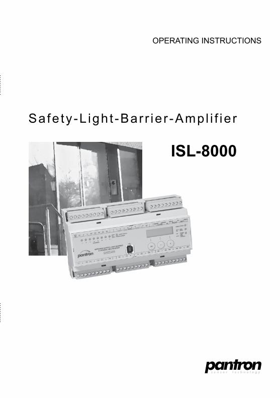
Operating instructiOns
safe ty -L igh t -Bar r ie r -ampl i f ie r
ISL-8000

3© Pantron Instruments GmbH
Operating instructions ISL-8000
Safety-Light-Barrier-Amplifier ISL-8000
Operating instructions (english translation)state of the art: 19.05.2016
this Manual refers to devices manufactured since May 2016(ref. 01/04).
4 © Pantron Instruments GmbH
Operating instructions ISL-8000 table of contents
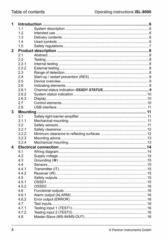
1 Introduction �����������������������������������������������������������������������������������������������61.1 system description ...................................................................................61.2 intended use .............................................................................................61.3 Delivery contents ......................................................................................61.4 used symbols ...........................................................................................61.5 safety regulations .....................................................................................7
2 Product description ����������������������������������������������������������������������������������82.1 abstract .....................................................................................................82.2 testing ......................................................................................................82.2.1 internal testing ..........................................................................................82.2.2 external testing .........................................................................................82.3 range of detection ....................................................................................82.4 start-up / restart prevention (res) ...........................................................82.5 Device overview ........................................................................................92.6 indicating elements ...................................................................................92.6.1 channel status indication OSSD1 STATUS ����������������������������������������������92.6.2 system status indication .........................................................................102.6.3 Display ....................................................................................................102.7 control elements .....................................................................................102.8 usB interface .......................................................................................... 11
3 Mounting �������������������������������������������������������������������������������������������������� 113.1 Safety-light-barrier-amplifier ................................................................... 113.1.1 Mechanical mounting .............................................................................. 113.2 safety sensors ........................................................................................ 113.2.1 safety clearance .....................................................................................123.2.2 Minimum clearance to reflecting surfaces ..............................................123.2.3 Mounting advice ......................................................................................133.2.4 Mechanical mounting ..............................................................................13
4 Electrical connection ������������������������������������������������������������������������������144.1 Wiring diagram ........................................................................................144.2 supply voltage ........................................................................................144.3 grounding ( ) ........................................................................................154.4 sensors ...................................................................................................154.4.1 transmitter (it) .......................................................................................154.4.2 receiver (ir) ...........................................................................................154.5 safety outputs .........................................................................................154.5.1 OssD1 ....................................................................................................154.5.2 OssD2 ....................................................................................................164.6 Functional outputs ..................................................................................164.6.1 alarm output (aLarM) ............................................................................164.6.2 error output (errOr) ............................................................................164.7 test inputs ...............................................................................................164.7.1 testing input 1 (test1) ..........................................................................164.7.2 testing input 2 (test2) ..........................................................................164.8 Master-slave (Ms-in/Ms-Out) ..............................................................16
5© Pantron Instruments GmbH
Operating instructions ISL-8000 table of contents
5 Setting into operation �����������������������������������������������������������������������������175.1 Lichtschrankenverstärker in Betrieb nehmen .........................................175.2 adapt light-barriers .................................................................................185.3 align sensors ..........................................................................................195.4 Finishing installation ...............................................................................215.4.1 testing the channel assignment .............................................................215.4.2 testing detectability ................................................................................215.4.3 testing the testing inputs ........................................................................21
6 Handling ���������������������������������������������������������������������������������������������������226.1 Light-barrier-mode (run mode) ................................................................226.2 Displaying information ............................................................................226.2.1 Displaying light path information .............................................................226.2.2 software revision and date of construction .............................................236.2.3 serial number .........................................................................................236.3 Light-barrier setup ...................................................................................236.3.1 entering pin code ...................................................................................246.3.2 switching light-barrier channels on or off ................................................246.3.3 changing device settings ........................................................................256.3.3.1 activating / deactivating the cumulative output .......................................256.3.3.2 changing LcD contrast ..........................................................................266.3.3.3 changing the polarity of the testing inputs ..............................................266.3.4 aligning sensors / analyzing sensor failure / Verifying testing inputs .....276.3.4.1 aligning the light-barrier ..........................................................................276.3.4.2 analyzing sensor failure ..........................................................................286.3.4.3 Validating the testing input ......................................................................286.3.5 reset transmit power ..............................................................................286.3.6 restoring factory settings .......................................................................29
7 Error indication ����������������������������������������������������������������������������������������307.1 Error classification ..................................................................................307.2 power limit ..............................................................................................307.3 sensor failure ..........................................................................................317.4 external error ..........................................................................................317.5 internal error ...........................................................................................327.6 program execution error .........................................................................32
8 Regular inspection ����������������������������������������������������������������������������������329 Maintenance ���������������������������������������������������������������������������������������������3310 Technical Data �����������������������������������������������������������������������������������������3411 Dimensioned drawing �����������������������������������������������������������������������������3512 Type lable �������������������������������������������������������������������������������������������������3513 Appendix ��������������������������������������������������������������������������������������������������36
13.1 eu-Declaration of conformity ..................................................................3613.2 identity card ...........................................................................................37
6 © Pantron Instruments GmbH
Operating instructions ISL-8000introduction
1 Introduction1�1 System descriptionThe Safety-Light-Barrier-Amplifier ISL-8000, in conjunction with optical safety-transmitters and safety-receivers, yields a contactless protective device (BWS) according to EN 61496 Part 1 and Part 2.
1�2 Intended useThe Safety-Light-Barrier-Amplifier is used for personal protection in restricted areas near machines and plants. combined with optical safety-sensors (transmitter and receiver) it forms as safety one-way light-barrier. Sensors are installed in a fixed position at the entrance to the restricted area and connected to the safety-light-barrier-amplifier. The amplifier detects any interruption of a light-barrier route and reports the event at the assigned safety-output.Operation of the amplifier is only valid according to its technical specification. Any other use of the device as well as any modification of amplifier and/or sensors is prohibited.
1�3 Delivery contents - Safety-light-barrier-amplifier - Operating instructions - test specimen
1�4 Used symbolsthroughout this manual information of interest is highlighted by symbols.
Î
Î
This symbol indicates optional display or choice, whereby multiple selections are possible
Tip!This symbol indicates explanations or annotations regarding special features of the safety-light-amplifier.
Attention!this symbol indicates very important information or possible hazard.please read information with care and act accordingly.
7© Pantron Instruments GmbH
Operating instructions ISL-8000 introduction
1�5 Safety regulations
Hazard!the safety function may be affected if the device is used improperly or outside its technical specification. Disregarding the safety regulations may lead to serious injury or even death.
- the designer or operator of the overall system (e.g. a machine or plant) is responsible for applying all national or international safety and accident prevention regulations.
- Assembly and electrical wiring of the safety-light-barrier-amplifier is to be done only by skilled personnel according to applicable regulations.
- Assembly and electrical wiring of the safety-light-barrier-amplifier is to be done with target system switched off and power supply disconnected. the target system is to be secured against accidental activation.
- access or entry to the restricted area may only be possible via a safety clearance. - the target system needs to be electrically controllable. - Hazardous movement must come to a halt before reaching the restricted area. - examination and documentation is to be done by skilled personnel only or by authorized
and trained personnel respectively. - this manual must be added to the documentation of the superior system (machine or
plant) into which the protectional device (safety-light-barrier-amplifier) is integrated. The manual must be available throughout the entire period of use by all personnel engaged in construction, implementation, operation and maintenance. The legal operator must ensure that the operator on duty is instructed by skilled personnel.
- The safety-light-barrier-amplifier is not to be utilized as a light curtain in terms of EN 61496 part 2.
- Operation in dense fog or water vapor is likely to reduce the range of detection which applies to an object size not smaller than 10 mm.
- additional measures may be taken to ensure failure-free operation. attention as to be focused on special applications using different forms of light emission, e.g. optical data transmission systems, stroboscope lights, different optical safety equipment.
- Used in systems dealing with food, cosmetics or pharmaceuticals where applicable sensor types and material (plastics, stainless steel) must be utilized.
8 © Pantron Instruments GmbH
Operating instructions ISL-8000product description
2 Product description2�1 AbstractThe safety-light-barrier-amplifier ISL-8000... in conjunction with an optical safety -transmitter IST-.... and an optical safety-receiver isr-... forms a powerful light barrier whereby up to eight independent light barrier routes may be realized without mutual interference.The amplifier evaluates each single light-barrier route and reports the status , interrupted or clear, via the output OssD1 to the superior control system. every light-barrier route has a separate output. the integrity of the connection to the control system may be evaluated by using internal or external testing (see chapter 2�2 Testing).To reduce service effort and to equalize changing environmental conditions (e.g. sensor contamination), the transmit-power of every individual channel is constantly adjusted by the automatic power regulation. When the transmit power of a channel reaches 90% of maximum transmit power, this condition is reported by a alarm indicator and by activating the alarm output.Via an integrated usB-interface the device may be conveniently be programmed and controlled by a pc for servicing purposes. (software optionally available).
2�2 Testing
2�2�1 Internal testingDuring normal operation, continuously periodical self tests are executed. Both, the switching outputs OssD1 and the safety-output OssD2 must be connected to the superior control system and must be evaluated independently. In case of an error, both outputs will switch off.
2�2�2 External testingIn case evaluating safety -output OSSD2 is not possible, external testing must be executed. To do this, test-input 1 must be stimulated periodically by a test signal causing a reaction at the outputs OSSD1. For more information, refer to 4�7 Test inputs.
2�3 Range of detectionThe system is able to detect a transparent cylindrical test specimen with a diameter of 10 mm, which may be placed arbitrarily on the centerline between transmitter and receiver. the response time is at most 36 ms.
2�4 Start-up / restart prevention (RES)
Attention!The safety-light-barrier-amplifier does not employ start-up / restart prevention capability. As soon as a light-barrier-trace gains clear view, its assigned output OSSD1 will switch on. If restart prevention is necessary, it must be implemented by the superior control system.
9© Pantron Instruments GmbH
Operating instructions ISL-8000 product description
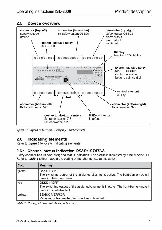
2�5 Device overview
INFRARED SAFETY LIGHT BARRIER
8-CHANNEL MULTIPLEXER
CHANNEL1 2 3 4 5 6 7 8
- ON- OFF- SENSOR ERROR
MS-IN
IT1 IT2 IT3 IT5IT4 IT8 IR1 IR2IT6 IT7 IR6 IR8IR7
NC
IR5IR3 IR4
RUNSTOP
greenred
--
POWERLIMITGAINCONTROL
red
green
-
-
NC NC NC NC NC 1 2 3 4 5 6 7 8MS-OUT TEST1
TEST2NCNC
ERRORALARM
DE/EU/US-patents
DC0V OSSD2
OSSD2 STATUS
OSSD124V
OSSD1 STATUS
connector (top left)supply voltageground
connector (top right)safety output OSSD2alarm outputerror outputtest input
connector (top center)8x safety output OSSD1
connector (bottom center)2x transmitter nr. 7-82x receiver nr. 1-2
connector (bottom right)6x receiver nr. 3-8
connector (bottom left)6x transmitter nr. 1-6
control element3x key
Displaytwo-line LCD-display
channel status display8x OSSD1
USB-connectorinterface
system status displaytop: OSSD2center: operationbottom: gain control
figure 1: Layout of terminals, displays and controls
2�6 Indicating elementsrefer to figure 1 to locate indicating elements.
2�6�1 Channel status indication OSSD1 STATUSevery channel has its own assigned status indication. the status is indicated by a multi color LeD. refer to table 1 to learn about the coding of the channel status indication.
Color Meaning
green OssD1 “On”the switching output of the assigned channel is active. the light-barrier-route in question has clear view.
red OssD1 “OFF”the switching output of the assigned channel is inactive. the light-barrier-route in question is obstructed.
yellow sensOr errOrreceiver or transmitter fault has been detected.
table 1: Coding of channel status indication
10 © Pantron Instruments GmbH
Operating instructions ISL-8000product description
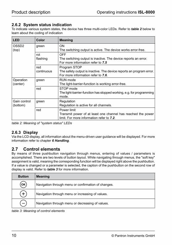
2�6�2 System status indicationTo indicate various system states, the device has three multi-color LEDs. Refer to table 2 below to learn about the coding of indication
LED Color Meaning
OssD2(top)
green Onthe switching output is active. the device works error-free.
rotflashing
OFFthe switching output is inactive. the device reports an error. For more information refer to 7�5
redcontinuous
program stOpthe safety output is inactive. the device reports an program error. For more information refer to 7�6.
Operation(center)
green run modethe light-barrier-function is working error-free.
red stOp modeThe light-barrier-function has stopped working, e.g. for programming mode.
gain control(bottom)
green regulationregulation is active for all channels.
red power limittransmit power of at least one channel has reached the power limit. For more information refer to 7�2.
table 2: Meaning of "system status" LEDs
2�6�3 DisplayVia the LCD display, all information about the menu-driven user guidance will be displayed. For more information refer to chapter 6 Handling.
2�7 Control elementsBy means of three pushbutton navigation through menus, entering of values / parameters is accomplished. There are two levels of button layout. While navigating through menus, the "soft key" assignment is valid, meaning the corresponding function will be displayed right above the pushbutton. If a value is changed or a parameter is selected, the caption of the pushbutton on the second row of display is valid. refer to table 3 for more information.
Button Meaning
Navigation through menu or confirmation of changes.
navigation through menu or increasing of values.
navigation through menu or decreasing of values.
table 3: Meaning of control elements
11© Pantron Instruments GmbH
Operating instructions ISL-8000 Mounting
2�8 USB interfaceFor servicing purposes a usB interface (universal serial Bus) is provided. using software application WinISL, the device may be programmed. Moreover various diagnostic functions may be accessed
Attention!The USB interface is not subject to constant safety surveillance and therefore must not be used as safety output!
3 Mounting3�1 Safety-light-barrier-amplifierThe safety-light-barrier-amplifier has enclosure type IP20 and is meant to be located in an electric cabinet or protective housing with enclosure type not less than IP54. The amplifier is to be mounted on a DIN rail NS35/7,5 resp. NS35/15 according to EN 60715. Assembly must be performed in such a manner that indicating elements of the device remain visible.nearby devices that radiate heat must be placed with a clearance not less than 20 mm away from the safety-light-barrier-amplifier. For electrical wiring a clearance of at least 15 mm top and bottom must be provided.
3�1�1 Mechanical mounting - the assembly must be performed in such a manner that no additional hazard will be
introduced. - Access to the safety-light-barrier-amplifier must be safely possible. - The safety-light-barrier-amplifier must not be placed within the restricted area. Sufficient
safety clearance must be provided. - The safety-light-barrier-amplifier must be firmly mounted such that it is secured against
falling off or accidental change of position. - If the safety-light-barrier-amplifier‘s power supply is separated by removing the connector,
provisions must be made that the permanent separation may be monitored from every access point of the restricted area.
3�2 Safety sensors
Attention!Using sensors without approval for use with safety-light-barrier-amplifiers leads to loss of the protective function. Only approved safety sensors may be used.
Mounting of safty sensors depends in accordance with Din en isO 13857 resp. en 999 on the type of protection:
- Hazardous spot protection - restricted area protection - access protection
For detailed information on safety distance, mounting heights, beam distance and resolution, refer to standards Din en isO 13857 and en 999.
12 © Pantron Instruments GmbH
Operating instructions ISL-8000Mounting
3�2�1 Safety clearancethe light-barrier and the restricted area must be separated by a safety clearance.this clearance must be wide enough that in case of a breach, it is impossible to reach the restricted area until the danger inducing motion has come to a halt.the safety clearance depends on:
- Follow-up time of the machine (stop-time) - Reaction time of the protective equipment - Resolution of the protective equipment - approximate speed towards the restricted area - arrangement of protective elements
according to standard en 999 the safety clearance width s for access or restricted area protection is determined by the equation:
s [mm] = K [mm/s] x t [s] + c [mm]s = safety clearance width in mmK = approximation speed in mm/st = Overall delay time measured in seconds = reaction time of the protective equipment + reaction time of the superior control system + follow-up time of the machinec = safety margin depending on penetration depth into safety clearance until safety-light-barrier-amplifier reactsFor detailed information, refer to standard EN 999.
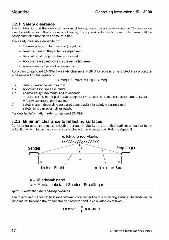
3�2�2 Minimum clearance to reflecting surfacesConsidering aperture angles, reflecting surface in vicinity to the optical path may lead to beam deflection which, in turn, may cause an obstacle to be disregarded. Refer to figure 2.
figure 2: Deflection on reflecting surfaces
The minimum distance “a” (distance of beam core center line to a reflecting surface) depends on the distance “b” between the transmitter and receiver and is calculated as follows:
a = tan 5° ·b
≈ 0,045 · b2
13© Pantron Instruments GmbH
Operating instructions ISL-8000 Mounting
example:If the distance between transmitter and receive is 10 m, the minimum clearance will result in:
a = 0,045 · 10 m = 0,45 m
3�2�3 Mounting adviceplease mind the advice below when mounting sensors:
- According to the technical specification, please validate if the sensors suit your application (also read “safety sensor guide”).
- Please verify that it is impossible to reach below, above or around the safety area as well as to step around it.
- position the light barrier in a distance not less than the minimum safety clearance in respect to the restricted area (refer to 3.2.1 Safety clearance)
- Observe the minimum clearance to reflective surfaces (refer to 3�2�2) - Keep in mind, that an object needs to be equal or larger than the specified detection
capability of the light barrier. - Do not exceed the specified distance between transmitter and receiver, as specified in
chapter 10 Technical Data.
3�2�4 Mechanical mountingthe type of mounting depends on the form factor of the individual sensor (refer to the dimensional drawing in “safety sensor guide”. please follow this advice when mounting sensors:
- Sensors may only be mounted to solid, non-vibrating components. - Once adjusted, sensors may not be accidentally displaced. - Disassembly may only be possible using tools.
14 © Pantron Instruments GmbH
Operating instructions ISL-8000electrical connection
4 Electrical connectionHazard!there is the risk of the machine starting up during the process of electrical installation. To counteract this, disconnect the power supply and secure against reactivation. Only after all protective functions of the safety equipment have been tested, may it be integrated into the safety circuit of the machine.
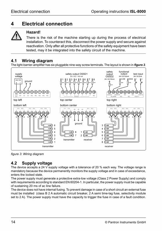
4�1 Wiring diagramThe light-barrier-amplifier has six pluggable nine-way screw terminals. The layout is shown in figure 3.
top center
NC
1110 12 13 14 15 16 17 18
safety output OSSD124 V DC / 150 mA
1 2 3 4 5 6 7 8OSSD1
1 2 3 4 5 6 7load load load load load load load
8load
NCNC
top right
2019 21 22 23 24 25 26 27
TEST1OSSD2
ALARMERROR
NC NCTEST2
safetyoutput
OSSD2
functionaloutput
24V DC/150mA
24V DC/100mA
test input24V DC/2mA
1 2
load
loadload
ALARM ERROR
supplyvoltage
24V DC
top left
24V
21 3 4 5 6 7 8 9
ground
NCNCNCNCNCDC
0V
bottom leftIT1 IT2 IT3 IT4 IT6IT5
2928 30 31 32 33 34 35 36
1
2
3
4
5
6
transmitter
bottom rightIR3 IR4 IR5 IR6 IR8IR7
4746 48 49 50 51 52 53 54
8
7
6
5
4
3
receiver
bottom centerIT7 IT8 IR2IR1
3837 39 40 41 42 43 44 45
7
8 1
2
ground
receivertransmitter
figure 3: Wiring diagram
4�2 Supply voltagethe device accepts a 24 V supply voltage with a tolerance of 20 % each way. the voltage range is mandatory because the device permanently monitors the supply voltage and in case of exceedance, enters the locked state.the power supply must generate a protective extra-low voltage (class 2 power supply) and comply with requirements according to standard EN 60204-1. In particular, the power supply must be capable of sustaining 20 ms of ac line failure.the device does not have internal fusing. to prevent damage in case of a short circuit an external fuse must be installed (class B 2 A automatic circuit breaker, 2 A semi time-lag fuse, selectivity module set to 2 a). the power supply must have the capacity to trigger the fuse in case of a fault condition.
15© Pantron Instruments GmbH
Operating instructions ISL-8000 electrical connection
4�3 Grounding ( )To comply with EMC regulations, earth ground must be connected (upper row: terminal 3 or 4, lower row: terminal 40, 41 or 42). The connection to the cabinet must be done via a low impedance cable using the shortest possible route.
4�4 Sensors
4�4�1 Transmitter (IT)The transmitter terminals are short circuit protected. Transmitter 1/2, 3/4, 5/6 and 7/8 share a common return path (-) terminal each.
TipThe return paths of all transmitters may be combined to a single common bus line connected to one of the transmitter “-” terminals. They may not be connected to ground or any other potential.
4�4�2 Receiver (IR)The receiver terminals are short circuit protected. Receiver 1/2, 3/4, 5/6 and 7/8 share a common return path (-) terminal each.
TipThe return paths of all receivers may be combined to a single common shielded bus line connected to one of the receiver “-” terminals. They may not be connected to ground or any other potential.
4�5 Safety outputsThe safety outputs are protected against short circuit and overload. The outputs are continuously, internally tested causing short-term level change in output signals, which must be ignored by the superior control system.the test pulses are only present while the output is in high state and have a pulse width of 100 µs. the maximum load-current is 100 ma at 24 V dc.
Attention!the safety outputs may not be connected to external pull up resistors. the superior control system has to be designed in a way to ensure low potential at the safety output in case of a wire break.
4�5�1 OSSD1the safety output OssD1 reports the status of the assigned light-barrier channel to the superior control system. In case of an unobstructed light path between transmitter and receiver, the output will be in high-state (24 V dc). In the presence of an obstacle, the output will be in low-state (0 V). the minimum low-time is 30 ms.
16 © Pantron Instruments GmbH
Operating instructions ISL-8000electrical connection
4�5�2 OSSD2In case the light-barrier-amplifier is operated without external testing, the safety output OSSD2 must be connected to the superior control system and analyzed independently of OssD1. During fault-free condition, safety output OSSD2 is in high state (24 V dc). In occurrence of an error, OSSD2 switches to low-state (0 V).
4�6 Functional outputs
Attention!Functional outputs are not (internally) tested and do not provide a protective function. these outputs may not be used as safety outputs.
Functional outputs provide additional information on the condition of the light-barrier-amplifier. permissible load-current is 100 ma at 24 V dc.
4�6�1 Alarm output (ALARM)the alarm output reports to the superior control system that at least one light-barrier channel has reached its power limit.
4�6�2 Error output (ERROR)the error output reports to the superior control system that at least one light-barrier sensor is in fault condition
4�7 Test inputs
4�7�1 Testing input 1 (TEST1)If the light-barrier-amplifier is operated with external testing, input TEST1 must periodically be driven by a test signal and the subsequent reaction of the outputs OSSD1 must be analyzed. Input TEST1 is stimulated with voltage levels of 24 V dc (high) or 0 V (low).as a reaction to the testing signal the outputs OssD1 are switched off if the device is working error-free. By removing the test signal, the outputs OSSD1 return to the normal states according to the status of the light-barrier routes. the delay time does not exceed 10 ms both ways. the test signal is supposed to have a pulse with not less than 29 ms and a dead time of at least 20 ms.
TipThe polarity of the testing signal may be inverted. The device must be programmed accordingly. Refer to 6�3�3�3 for more information.
4�7�2 Testing input 2 (TEST2)At present, no function is assigned to testing input TEST2.
4�8 Master-Slave (MS-IN/MS-OUT)Die Master-slave anschlüsse haben in der aktuellen Version keine Funktion.
17© Pantron Instruments GmbH
Operating instructions ISL-8000 setting into operation
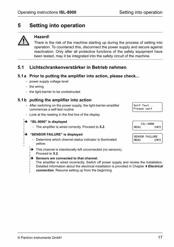
5 Setting into operation
Hazard!there is the risk of the machine starting up during the process of setting into operation. To counteract this, disconnect the power supply and secure against reactivation. Only after all protective functions of the safety equipment have been tested, may it be integrated into the safety circuit of the machine.
5�1 Lichtschrankenverstärker in Betrieb nehmen
5�1 a Prior to putting the amplifier into action, please check��� - power supply voltage level - the wiring - the light-barrier to be unobstructed
5�1 b putting the amplifier into action - After switching on the power supply, the light-barrier-amplifier
commences a self-test routine - Look at the reading in the first line of the display
Î “ISL-8000” is displayed - The amplifier is wired correctly. Proceed to 5�2�
��������
����������������
Î “SENSOR FAILURE” is displayed - Determine which channel status indicator is illuminated
yellow.
Î this channel is intentionally left unconnected (no sensors)� proceed to 5�2�
Î Sensors are connected to that channel�The amplifier is wired incorrectly. Switch off power supply and review the installation. Detailed information about the electrical installation is provided in chapter 4 Electrical connection. resume setting up from the beginning.
18 © Pantron Instruments GmbH
Operating instructions ISL-8000setting into operation
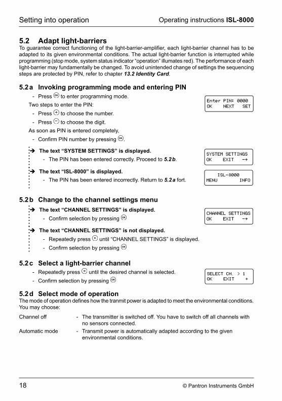
5�2 Adapt light-barriersTo guarantee correct functioning of the light-barrier-amplifier, each light-barrier channel has to be adapted to its given environmental conditions. the actual light-barrier function is interrupted while programming (stop mode, system status indicator “operation” illumates red). The performance of each light-barrier may fundamentally be changed. To avoid unintended change of settings the sequencing steps are protected by PIN, refer to chapter 13.2 Identity Card.
5�2 a Invoking programming mode and entering PIN - press to enter programming mode.
two steps to enter the pin: - press to choose the number. - press to choose the digit.
As soon as PIN is entered completely, - Confirm PIN number by pressing .
Î The text “SYSTEM SETTINGS” is displayed� - the pin has been entered correctly. proceed to 5�2 b.
Î The text “ISL-8000” is displayed� - the pin has been entered incorrectly. return to 5�2 a fort.
��������
����������������
5�2 b Change to the channel settings menu Î The text “CHANNEL SETTINGS” is displayed�
- Confirm selection by pressing
Î The text “CHANNEL SETTINGS” is not displayed� - repeatedly press until “cHanneL settings” is displayed. - Confirm selection by pressing
5�2 c Select a light-barrier channel - repeatedly press until the desired channel is selected. - Confirm selection by pressing
5�2 d Select mode of operationThe mode of operation defines how the tranmit power is adapted to meet the environmental conditions. You may choose:
channel off - the transmitter is switched off. You have to switch off all channels with no sensors connected.
automatic mode - transmit power is automatically adapted according to the given environmental conditions.
19© Pantron Instruments GmbH
Operating instructions ISL-8000 setting into operation
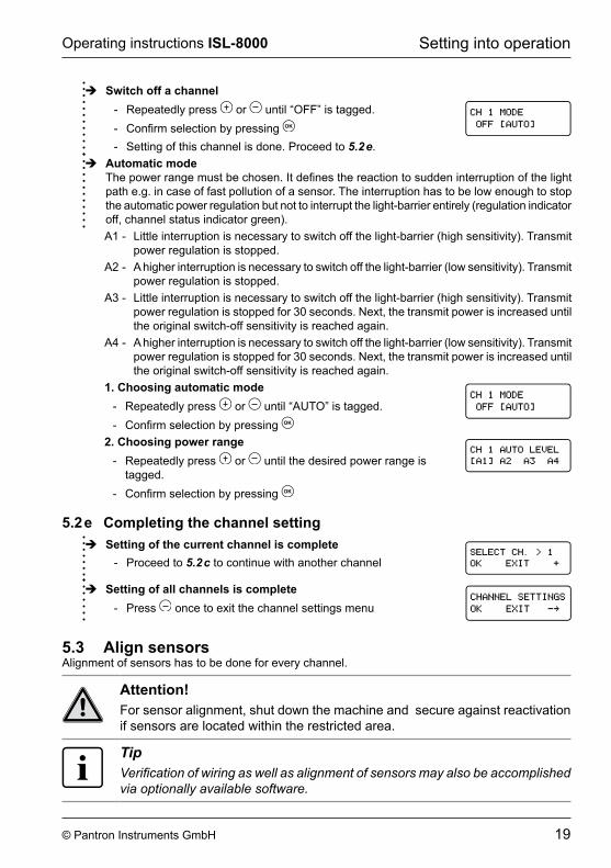
Î Switch off a channel - repeatedly press or until “OFF” is tagged. - Confirm selection by pressing - setting of this channel is done. proceed to 5�2 e.
Î Automatic modeThe power range must be chosen. It defines the reaction to sudden interruption of the light path e.g. in case of fast pollution of a sensor. the interruption has to be low enough to stop the automatic power regulation but not to interrupt the light-barrier entirely (regulation indicator off, channel status indicator green). a1 - Little interruption is necessary to switch off the light-barrier (high sensitivity). transmit
power regulation is stopped.a2 - a higher interruption is necessary to switch off the light-barrier (low sensitivity). transmit
power regulation is stopped.a3 - Little interruption is necessary to switch off the light-barrier (high sensitivity). transmit
power regulation is stopped for 30 seconds. Next, the transmit power is increased until the original switch-off sensitivity is reached again.
a4 - a higher interruption is necessary to switch off the light-barrier (low sensitivity). transmit power regulation is stopped for 30 seconds. Next, the transmit power is increased until the original switch-off sensitivity is reached again.
1� Choosing automatic mode - repeatedly press or until “autO” is tagged. - Confirm selection by pressing
2� Choosing power range - repeatedly press or until the desired power range is
tagged. - Confirm selection by pressing
5�2 e Completing the channel setting Î Setting of the current channel is complete
- proceed to 5�2 c to continue with another channel
Î Setting of all channels is complete - press once to exit the channel settings menu
5�3 Align sensorsalignment of sensors has to be done for every channel.
Attention!For sensor alignment, shut down the machine and secure against reactivation if sensors are located within the restricted area.
TipVerification of wiring as well as alignment of sensors may also be accomplished via optionally available software.
20 © Pantron Instruments GmbH
Operating instructions ISL-8000setting into operation
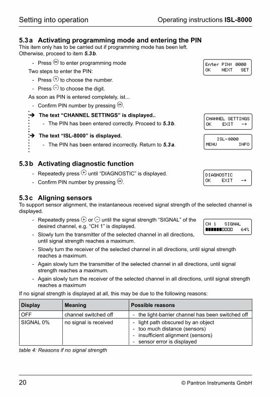
5�3 a Activating programming mode and entering the PINthis item only has to be carried out if programming mode has been left. Otherwise, proceed to item 5�3 b.
- press to enter programming modetwo steps to enter the pin:
- press to choose the number. - press to choose the digit.
As soon as PIN is entered completely, ist... - Confirm PIN number by pressing .
Î The text “CHANNEL SETTINGS” is displayed�� - the pin has been entered correctly. proceed to 5�3 b.
Î The text “ISL-8000” is displayed� - the pin has been entered incorrectly. return to 5�3 a.
��������
����������������
5�3 b Activating diagnostic function - repeatedly press until “DiagnOstic” is displayed. - Confirm PIN number by pressing .
5�3 c Aligning sensorsTo support sensor alignment, the instantaneous received signal strength of the selected channel is displayed.
- repeatedly press or until the signal strength “signaL” of the desired channel, e.g. “CH 1” is displayed.
- Slowly turn the transmitter of the selected channel in all directions, until signal strength reaches a maximum.
- Slowly turn the receiver of the selected channel in all directions, until signal strength reaches a maximum.
- Again slowly turn the transmitter of the selected channel in all directions, until signal strength reaches a maximum.
- Again slowly turn the receiver of the selected channel in all directions, until signal strength reaches a maximum
If no signal strength is displayed at all, this may be due to the following reasons:
Display Meaning Possible reasons
OFF channel switched off - the light-barrier channel has been switched offsignaL 0% no signal is received - light path obscured by an object
- too much distance (sensors) - insufficient alignment (sensors) - sensor error is displayed
table 4: Reasons if no signal strength
21© Pantron Instruments GmbH
Operating instructions ISL-8000 setting into operation
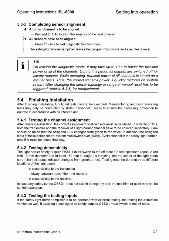
5�3 d Completing sensor alignment Î Another channel is to be aligned
- proceed to 5�3 c to align the sensors of the next channel Î All sensors have been aligned
- press once to exit diagnostic function menu.The safety-light-barrier-amplifier leaves the programming mode and executes a reset.
TipOn leaving the diagnostic mode, it may take up to 10 s to adjust the transmit power of all of the channels. During this period all outputs are switched off for savety reasons. While operating, transmit power of all channels is stored on a regular basis. Thus, the correct transmit power is quickly restored on system restart. After changing the sensor topology or range a manual reset has to be triggered (refer to 6�3�5) for readjustment.
5�4 Finishing installationAfter finishing installation, functional tests have to be executed. Manufacturing and commissioning tests may only be conducted by skilled personnel. this is to ensure the necessary protection to operate in accordance with its intented use.
5�4�1 Testing the channel assignmentAfter finishing installation, the correct assignment of all sensors must be validated. In order to do this, both the transmitter and the receiver of a light-barrier channel have to be covered separately. care should be taken that the assigned LED changes from green to red twice. In addition, the assigned input of the superior control system must switch over (twice). every channel of the safety-light-barrier-amplifier must be tested that way.
5�4�2 Testing detectabilityThe light-barrier safety outputs OSSD1 must switch to the off-state if a test specimen (opaque rod with 10 mm diameter and at least 150 mm in length) is intruding into the center of the light beam core (channel status indicator changes from green to red). testing must be done at three different locations of the light beam:
- in close vicinity to the transmitter - midway between transmitter and receiver - in close vicinity to the receiver
In case any safety output OSSD1 does not switch during any test, the machine or plant may not be set into operation.
5�4�3 Testing the testing inputsIf the safety-light-barrier-amplifier is to be operated with external testing, the testing input must be verified as well. If applying a test signal all safety outputs OSSD1 must switch to the off-state.
22 © Pantron Instruments GmbH
Operating instructions ISL-8000Handling
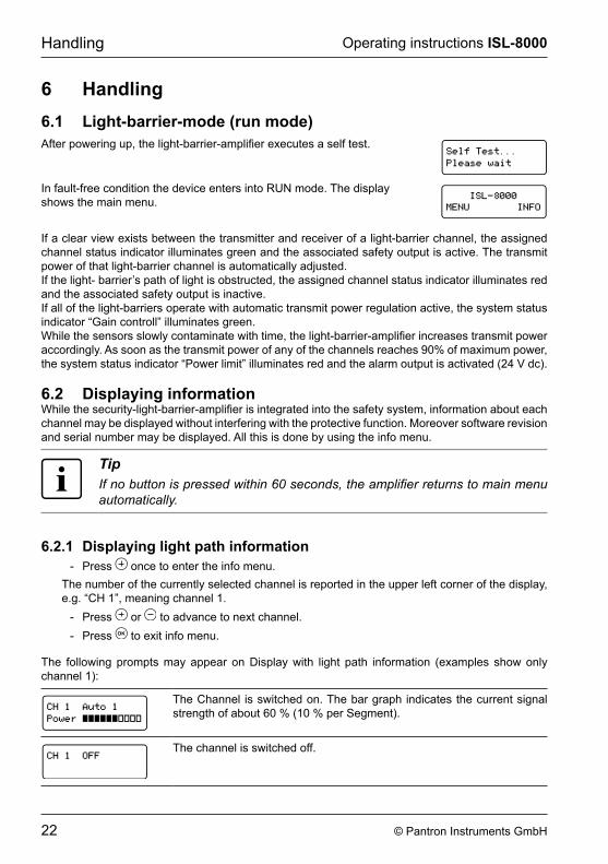
6 Handling6�1 Light-barrier-mode (run mode)After powering up, the light-barrier-amplifier executes a self test.
in fault-free condition the device enters into run mode. the display shows the main menu. ��������
����������������
If a clear view exists between the transmitter and receiver of a light-barrier channel, the assigned channel status indicator illuminates green and the associated safety output is active. the transmit power of that light-barrier channel is automatically adjusted.If the light- barrier’s path of light is obstructed, the assigned channel status indicator illuminates red and the associated safety output is inactive.If all of the light-barriers operate with automatic transmit power regulation active, the system status indicator “gain controll” illuminates green. While the sensors slowly contaminate with time, the light-barrier-amplifier increases transmit power accordingly. As soon as the transmit power of any of the channels reaches 90% of maximum power, the system status indicator “power limit” illuminates red and the alarm output is activated (24 V dc).
6�2 Displaying informationWhile the security-light-barrier-amplifier is integrated into the safety system, information about each channel may be displayed without interfering with the protective function. Moreover software revision and serial number may be displayed. all this is done by using the info menu.
TipIf no button is pressed within 60 seconds, the amplifier returns to main menu automatically.
6�2�1 Displaying light path information - press once to enter the info menu.
The number of the currently selected channel is reported in the upper left corner of the display, e.g. “CH 1”, meaning channel 1.
- press or to advance to next channel. - press to exit info menu.
the following prompts may appear on Display with light path information (examples show only channel 1):
the channel is switched on. the bar graph indicates the current signal strength of about 60 % (10 % per segment).
the channel is switched off.
23© Pantron Instruments GmbH
Operating instructions ISL-8000 Handling
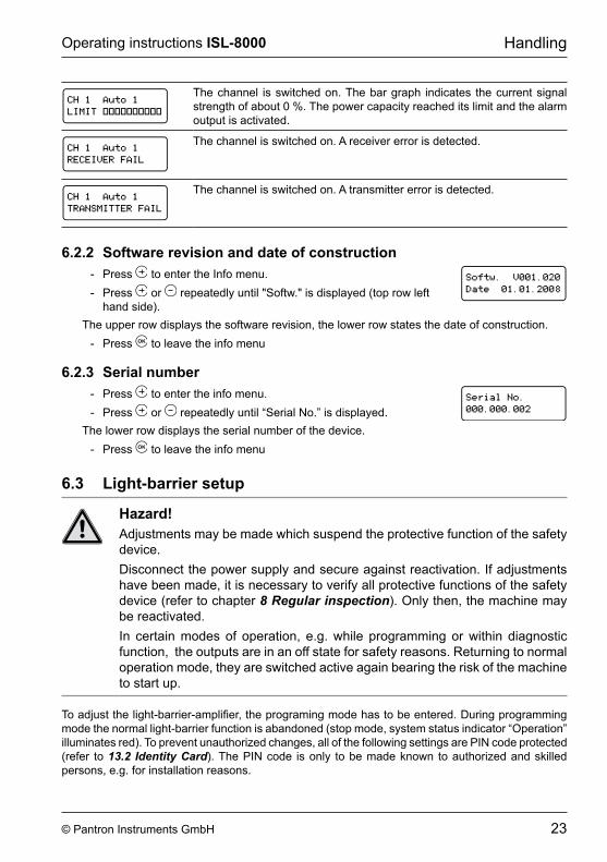
the channel is switched on. the bar graph indicates the current signal strength of about 0 %. the power capacity reached its limit and the alarm output is activated.
the channel is switched on. a receiver error is detected.
the channel is switched on. a transmitter error is detected.
6�2�2 Software revision and date of construction - press to enter the info menu. - press or repeatedly until "Softw." is displayed (top row left
hand side).The upper row displays the software revision, the lower row states the date of construction.
- press to leave the info menu
6�2�3 Serial number - press to enter the info menu. - press or repeatedly until “serial no.” is displayed.
the lower row displays the serial number of the device. - press to leave the info menu
6�3 Light-barrier setup
Hazard!Adjustments may be made which suspend the protective function of the safety device.Disconnect the power supply and secure against reactivation. If adjustments have been made, it is necessary to verify all protective functions of the safety device (refer to chapter 8 Regular inspection). Only then, the machine may be reactivated.In certain modes of operation, e.g. while programming or within diagnostic function, the outputs are in an off state for safety reasons. Returning to normal operation mode, they are switched active again bearing the risk of the machine to start up.
To adjust the light-barrier-amplifier, the programing mode has to be entered. During programming mode the normal light-barrier function is abandoned (stop mode, system status indicator “Operation” illuminates red). To prevent unauthorized changes, all of the following settings are PIN code protected (refer to 13.2 Identity Card). the pin code is only to be made known to authorized and skilled persons, e.g. for installation reasons.
24 © Pantron Instruments GmbH
Operating instructions ISL-8000Handling
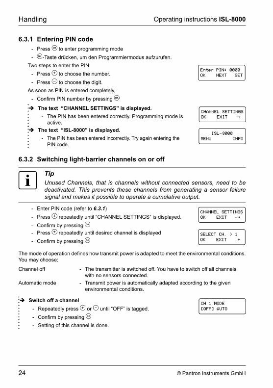
6�3�1 Entering PIN code - press to enter programming mode - -Taste drücken, um den Programmiermodus aufzurufen.
two steps to enter the pin: - press to choose the number. - press to choose the digit.
As soon as PIN is entered completely, - Confirm PIN number by pressing
Î The text “CHANNEL SETTINGS” is displayed� - the pin has been entered correctly. programming mode is
active. Î The text “ISL-8000” is displayed�
- the pin has been entered incorrectly. try again entering the pin code.
��������
����������������
6�3�2 Switching light-barrier channels on or off
TipUnused Channels, that is channels without connected sensors, need to be deactivated. This prevents these channels from generating a sensor failure signal and makes it possible to operate a cumulative output.
- enter pin code (refer to 6�3�1) - press repeatedly until “cHanneL settings” is displayed. - Confirm by pressing - press repeatedly until desired channel is displayed - Confirm by pressing
The mode of operation defines how transmit power is adapted to meet the environmental conditions. You may choose:
channel off - the transmitter is switched off. You have to switch off all channels with no sensors connected.
automatic mode - transmit power is automatically adapted according to the given environmental conditions.
Î Switch off a channel - repeatedly press or until “OFF” is tagged. - Confirm by pressing - setting of this channel is done.
25© Pantron Instruments GmbH
Operating instructions ISL-8000 Handling
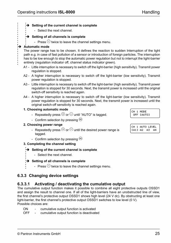
Î Setting of the current channel is complete - select the next channel.
Î Setting of all channels is complete - press twice to leave the channel settings menu.
Î Automatic modeThe power range has to be chosen. It defines the reaction to sudden Interruption of the light path e.g. in case of fast pollution of a sensor or introduction of foreign particles. the interruption has to be low enough to stop the automatic power regulation but not to interrupt the light-barrier entirely (regulation indicator off, channel status indicator green).a1 - Little interruption is necessary to switch off the light-barrier (high sensitivity). transmit power
regulation is stopped.a2 - a higher interruption is necessary to switch off the light-barrier (low sensitivity). transmit
power regulation is stopped.a3 - Little interruption is necessary to switch off the light-barrier (high sensitivity). transmit power
regulation is stopped for 30 seconds. Next, the transmit power is increased until the original switch-off sensitivity is reached again.
a4 - a higher interruption is necessary to switch off the light-barrier (low sensitivity). transmit power regulation is stopped for 30 seconds. Next, the transmit power is increased until the original switch-off sensitivity is reached again.
1� Choosing automatic mode - repeatedly press or until “autO” is tagged. - Confirm selection by pressing
2� Choosing power range - repeatedly press or until the desired power range is
tagged. - Confirm selection by pressing
3� Completing the channel setting
Î Setting of the current channel is complete - select the next channel.
Î Setting of all channels is complete - press twice to leave the channel settings menu.
6�3�3 Changing device settings
6�3�3�1 Activating / deactivating the cumulative outputthe cumulative output function makes it possible to combine all eight protective outputs OssD1 and assign the result to channel one. If all of the light-barriers have an unobstructed line of view, the first channel’s protective output OSSD1 shows high level (24 V dc). By obstructing at least one light-barrier, the first channel’s protective output OSSD1 switches to low level (0 V).possible choices are: On - cumulative output function is activated OFF - cumulative output function is deactivated
26 © Pantron Instruments GmbH
Operating instructions ISL-8000Handling
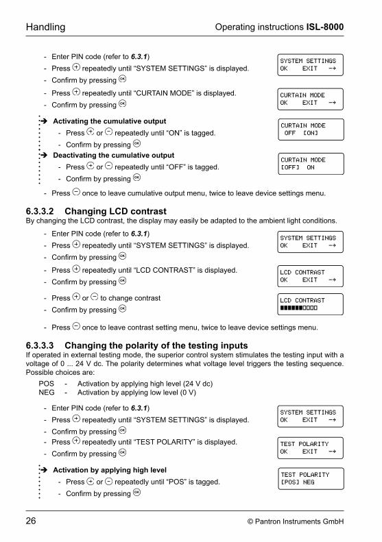
- enter pin code (refer to 6�3�1) - press repeatedly until “sYsteM settings” is displayed. - Confirm by pressing
- press repeatedly until “curtain MODe” is displayed. - Confirm by pressing
Î Activating the cumulative output - press or repeatedly until “On” is tagged. - Confirm by pressing
Î Deactivating the cumulative output - press or repeatedly until “OFF” is tagged. - Confirm by pressing
- press once to leave cumulative output menu, twice to leave device settings menu.
6�3�3�2 Changing LCD contrastBy changing the LCD contrast, the display may easily be adapted to the ambient light conditions.
- enter pin code (refer to 6�3�1) - press repeatedly until “sYsteM settings” is displayed. - Confirm by pressing
- press repeatedly until “LcD cOntrast” is displayed. - Confirm by pressing
- press or to change contrast - Confirm by pressing
- press once to leave contrast setting menu, twice to leave device settings menu.
6�3�3�3 Changing the polarity of the testing inputsIf operated in external testing mode, the superior control system stimulates the testing input with a voltage of 0 ... 24 V dc. The polarity determines what voltage level triggers the testing sequence. possible choices are: pOs - activation by applying high level (24 V dc) neg - activation by applying low level (0 V)
- enter pin code (refer to 6�3�1) - press repeatedly until “sYsteM settings” is displayed. - Confirm by pressing - press repeatedly until “test pOLaritY” is displayed. - Confirm by pressing
Î Activation by applying high level - press or repeatedly until “pOs” is tagged. - Confirm by pressing
27© Pantron Instruments GmbH
Operating instructions ISL-8000 Handling
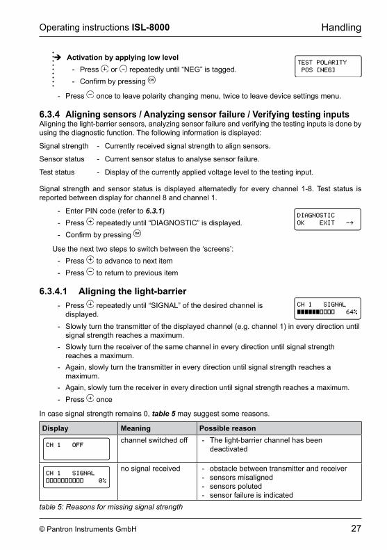
Î Activation by applying low level - press or repeatedly until “neg” is tagged. - Confirm by pressing
- press once to leave polarity changing menu, twice to leave device settings menu.
6�3�4 Aligning sensors / Analyzing sensor failure / Verifying testing inputsAligning the light-barrier sensors, analyzing sensor failure and verifying the testing inputs is done by using the diagnostic function. the following information is displayed:
signal strength - currently received signal strength to align sensors.
sensor status - current sensor status to analyse sensor failure.
test status - Display of the currently applied voltage level to the testing input.
signal strength and sensor status is displayed alternatedly for every channel 1-8. test status is reported between display for channel 8 and channel 1.
- enter pin code (refer to 6�3�1) - press repeatedly until “DiagnOstic” is displayed. - Confirm by pressing
Use the next two steps to switch between the ‘screens’: - press to advance to next item - press to return to previous item
6�3�4�1 Aligning the light-barrier - press repeatedly until “signaL” of the desired channel is
displayed. - slowly turn the transmitter of the displayed channel (e.g. channel 1) in every direction until
signal strength reaches a maximum. - slowly turn the receiver of the same channel in every direction until signal strength
reaches a maximum. - Again, slowly turn the transmitter in every direction until signal strength reaches a
maximum. - Again, slowly turn the receiver in every direction until signal strength reaches a maximum. - press once
In case signal strength remains 0, table 5 may suggest some reasons.
Display Meaning Possible reasonchannel switched off - the light-barrier channel has been
deactivated
no signal received - obstacle between transmitter and receiver - sensors misaligned - sensors poluted - sensor failure is indicated
table 5: Reasons for missing signal strength
28 © Pantron Instruments GmbH
Operating instructions ISL-8000Handling
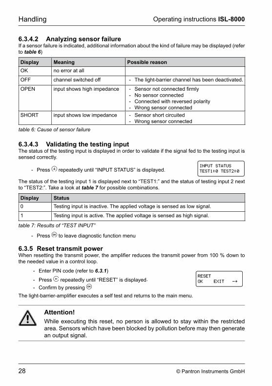
6�3�4�2 Analyzing sensor failureIf a sensor failure is indicated, additional information about the kind of failure may be displayed (refer to table 6)
Display Meaning Possible reasonOK no error at all
OFF channel switched off - the light-barrier channel has been deactivated.
Open input shows high impedance - Sensor not connected firmly - no sensor connected - connected with reversed polarity - Wrong sensor connected
sHOrt input shows low impedance - sensor short circuited - Wrong sensor connected
table 6: Cause of sensor failure
6�3�4�3 Validating the testing inputthe status of the testing input is displayed in order to validate if the signal fed to the testing input is sensed correctly.
- press repeatedly until “input status” is displayed.
the status of the testing input 1 is displayed next to “test1:” and the status of testing input 2 next to “test2:”. take a look at table 7 for possible combinations.
Display Status0 testing input is inactive. the applied voltage is sensed as low signal.
1 testing input is active. the applied voltage is sensed as high signal.
table 7: Results of “TEST INPUT”
- press to leave diagnostic function menu
6�3�5 Reset transmit powerWhen resetting the transmit power, the amplifier reduces the transmit power from 100 % down to the needed value in a control loop.
- enter pin code (refer to 6�3�1)
- press repeatedly until “reset” is displayed. - Confirm by pressing
The light-barrier-amplifier executes a self test and returns to the main menu.
Attention!While executing this reset, no person is allowed to stay within the restricted area. sensors which have been blocked by pollution before may then generate an output signal.
29© Pantron Instruments GmbH
Operating instructions ISL-8000 Handling
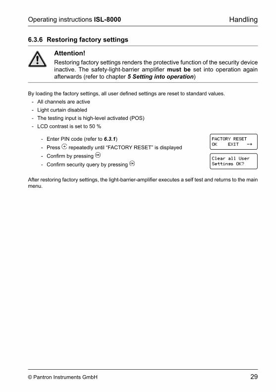
6�3�6 Restoring factory settings
Attention!restoring factory settings renders the protective function of the security device inactive. The safety-light-barrier amplifier must be set into operation again afterwards (refer to chapter 5 Setting into operation)
By loading the factory settings, all user defined settings are reset to standard values. - all channels are active - Light curtain disabled - the testing input is high-level activated (pOs) - LcD contrast is set to 50 %
- enter pin code (refer to 6�3�1) - press repeatedly until “FactOrY reset” is displayed - Confirm by pressing - Confirm security query by pressing
�������������
���������������
After restoring factory settings, the light-barrier-amplifier executes a self test and returns to the main menu.
30 © Pantron Instruments GmbH
Operating instructions ISL-8000error indication
7 Error indicationAttention!Troubleshooting should be done by skilled personnel only. After error-correction, all protective functions of the security device have to be validated (refer to chapter 8 Regular inspection). Only then the machine or plant may be set into operation.
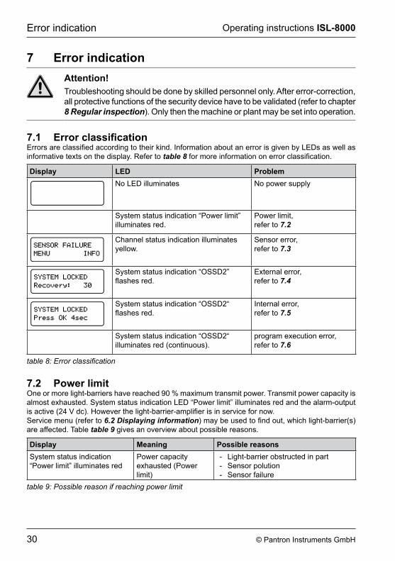
7�1 Error classificationErrors are classified according to their kind. Information about an error is given by LEDs as well as informative texts on the display. refer to table 8 for more information on error classification.
Display LED Problemno LeD illuminates no power supply
system status indication “power limit” illuminates red.
Power limit, refer to 7�2
channel status indication illuminates yellow.
Sensor error, refer to 7�3
system status indication “OssD2” flashes red.
External error, refer to 7�4
system status indication “OssD2“ flashes red.
Internal error, refer to 7�5
system status indication “OssD2“ illuminates red (continuous).
program execution error, refer to 7�6
table 8: Error classification
7�2 Power limitOne or more light-barriers have reached 90 % maximum transmit power. transmit power capacity is almost exhausted. system status indication LeD “power limit” illuminates red and the alarm-output is active (24 V dc). However the light-barrier-amplifier is in service for now.service menu (refer to 6.2 Displaying information) may be used to find out, which light-barrier(s) are affected. table table 9 gives an overview about possible reasons.
Display Meaning Possible reasonssystem status indication “power limit” illuminates red
power capacity exhausted (power limit)
- Light-barrier obstructed in part - sensor polution - sensor failure
table 9: Possible reason if reaching power limit
31© Pantron Instruments GmbH
Operating instructions ISL-8000 error indication
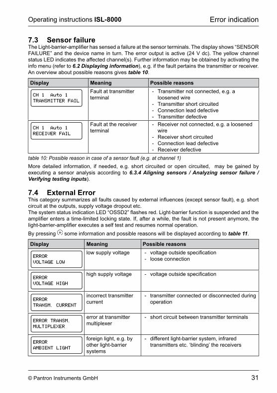
7�3 Sensor failureThe Light-barrier-amplifier has sensed a failure at the sensor terminals. The display shows “SENSOR FaiLure” and the device name in turn. the error output is active (24 V dc). the yellow channel status LeD indicates the affected channel(s). Further information may be obtained by activating the info menu (refer to 6.2 Displaying information), e.g. if the fault pertains the transmitter or receiver. an overview about possible reasons gives table 10.
Display Meaning Possible reasonsFault at transmitter terminal
- Transmitter not connected, e.g. a loosened wire
- transmitter short circuited - connection lead defective - transmitter defective
Fault at the receiver terminal
- Receiver not connected, e.g. a loosened wire
- receiver short circuited - connection lead defective - receiver defective
table 10: Possible reason in case of a sensor fault (e.g. at channel 1)More detailed information, if needed, e.g. short circuited or open circuited, may be gained by executing a sensor analysis according to 6.3.4 Aligning sensors / Analyzing sensor failure / Verifying testing inputs).
7�4 External ErrorThis category summarizes all faults caused by external influences (except sensor fault), e.g. short circuit at the outputs, supply voltage dropout etc.The system status indication LED “OSSD2” flashes red. Light-barrier function is suspended and the amplifier enters a time-limited locking state. If, after a while, the fault is not present anymore, the light-barrier-amplifier executes a self test and resumes normal operation.By pressing some information and possible reasons will be displayed according to table 11.
Display Meaning Possible reasonslow supply voltage - voltage outside specification
- loose connection
high supply voltage - voltage outside specification
incorrect transmitter current
- transmitter connected or disconnected during operation
error at transmitter multiplexer
- short circuit between transmitter terminals
foreign light, e.g. by other light-barrier systems
- different light-barrier system, infrared transmitters etc. ‘blinding’ the receivers
32 © Pantron Instruments GmbH
Operating instructions ISL-8000regular inspection
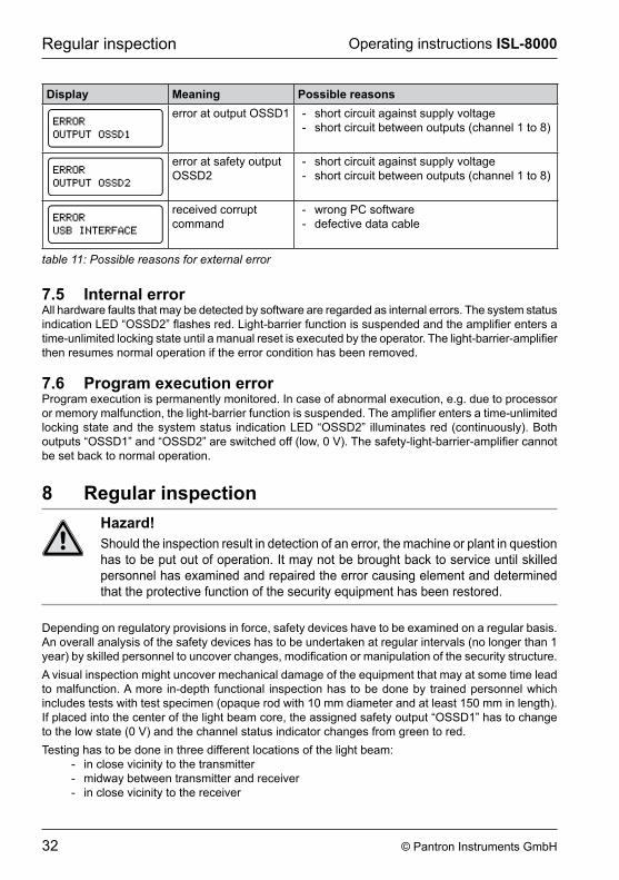
Display Meaning Possible reasonserror at output OssD1 - short circuit against supply voltage
- short circuit between outputs (channel 1 to 8)
error at safety output OssD2
- short circuit against supply voltage - short circuit between outputs (channel 1 to 8)
received corruptcommand
- wrong pc software - defective data cable
table 11: Possible reasons for external error
7�5 Internal errorall hardware faults that may be detected by software are regarded as internal errors. the system status indication LED “OSSD2” flashes red. Light-barrier function is suspended and the amplifier enters a time-unlimited locking state until a manual reset is executed by the operator. The light-barrier-amplifier then resumes normal operation if the error condition has been removed.
7�6 Program execution errorProgram execution is permanently monitored. In case of abnormal execution, e.g. due to processor or memory malfunction, the light-barrier function is suspended. The amplifier enters a time-unlimited locking state and the system status indication LeD “OssD2” illuminates red (continuously). Both outputs “OSSD1” and “OSSD2” are switched off (low, 0 V). The safety-light-barrier-amplifier cannot be set back to normal operation.
8 Regular inspectionHazard!Should the inspection result in detection of an error, the machine or plant in question has to be put out of operation. it may not be brought back to service until skilled personnel has examined and repaired the error causing element and determined that the protective function of the security equipment has been restored.
Depending on regulatory provisions in force, safety devices have to be examined on a regular basis. an overall analysis of the safety devices has to be undertaken at regular intervals (no longer than 1 year) by skilled personnel to uncover changes, modification or manipulation of the security structure. A visual inspection might uncover mechanical damage of the equipment that may at some time lead to malfunction. a more in-depth functional inspection has to be done by trained personnel which includes tests with test specimen (opaque rod with 10 mm diameter and at least 150 mm in length). If placed into the center of the light beam core, the assigned safety output “OSSD1” has to change to the low state (0 V) and the channel status indicator changes from green to red.testing has to be done in three different locations of the light beam:
- in close vicinity to the transmitter - midway between transmitter and receiver - in close vicinity to the receiver
33© Pantron Instruments GmbH
Operating instructions ISL-8000 Maintenance
In the case that any safety output does not respond at any of the tests, the machine or plant may not be set into operation.
9 MaintenanceThe safety-light-barrier-amplifier does not need maintenance.
34 © Pantron Instruments GmbH
Operating instructions ISL-8000technical Data
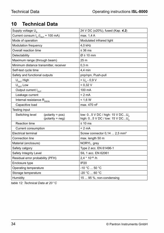
10 Technical Datasupply voltage us 24 V DC (±20%), fused (Kap. 4�2)current consum is (iOut = 100 ma) max. 1,4 AMode of operation Modulated infrared lightModulation frequency 4,0 kHzOverall reaction time ≤ 36 msDetectability Ø ≥ 10 mmMaximum range (through beam) 25 mMinimum distance transmitter, receiver 0,3 mself-test cycle time 4,4 minsafety and functional outputs pnp/npn, Push-pull
uOut High > us - 0,9 VuOut Low < 0,32 VOutput current iOut 100 maLeakage current < 2 mainternal resistance rDsOn < 1,6 Wcapacitive load max. 470 nF
testing inputswitching level (polarity = pos) (polarity = neg)
low: 0...5 V Dc / high: 15 V Dc...ushigh: 0...5 V Dc / low: 15 V Dc...us
reaction time ≤ 10 mscurrent consumption < 2 ma
electrical terminal Screw connector 0,14 ... 2,5 mm²connection line max. length 50 mMaterial (enclosure) NORYL, greysafety catgory type 2 acc. en 61496-1safety integrity Level siL 1 acc. en 62061residual error probability (pFH) 2,4 * 10-08 /henclosure type ip20Operating temperature -10 °c ... 50 °cstorage temperature -20 °c ... 60 °cHumidity 15 ... 95 %, non-condensing
table 12: Technical Data at 20 °C
35© Pantron Instruments GmbH
Operating instructions ISL-8000 Dimensioned drawing
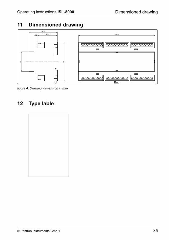
11 Dimensioned drawing
figure 4: Drawing, dimension in mm
12 Type lable
36 © Pantron Instruments GmbH
Operating instructions ISL-8000appendix
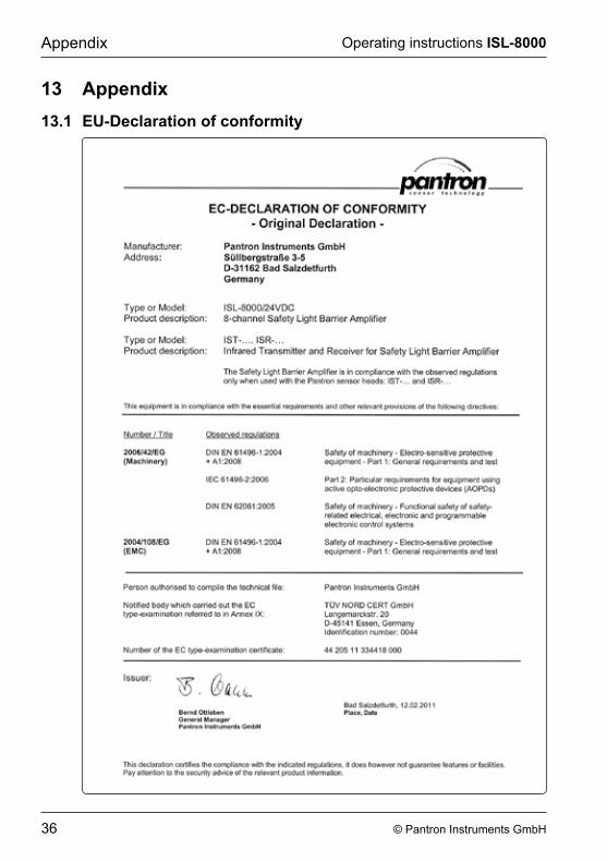
13 Appendix13�1 EU-Declaration of conformity

37© Pantron Instruments GmbH
Operating instructions ISL-8000 appendix
13�2 Identity Card
To prevent unauthorized changes, all settings are PIN code protected (Identity Card). The PIN code is only to be made known to authorized and skilled persons, e.g. for installation reasons.
separate this page from the manual and store it at a secret and safe location apart from the safety-light-barrier-amplifier.
Device number pin number
pantron instruments gmbHsüllbergstraße 3-5
31162 Bad salzdetfurthgermany
phone: +49 (0) 5063/9591-0 • Telefax: +49 (0) 5063/9591-55Internet: www.pantron.de • E-Mail: [email protected]

38 © Pantron Instruments GmbH
Operating instructions ISL-8000


pantron instruments gmbHsüllbergstraße 3-5
31162 Bad salzdetfurthgermany
phone: +49 (0) 5063/9591-0 • Telefax: +49 (0) 5063/9591-55Internet: www.pantron.de • E-Mail: [email protected] ©
Pan
tron
Inst
rum
ents
Gm
bH
• O
I160
402E
N
• S
tate
of t
he a
rt: 1
9.05
.201
6