Embed Size (px)
Citation preview

Safety Light Technology(SLT Series)
Installationand
Operation Manual


Safety Sensors and Controls for Industry
tems
Safety Light Curtains
Ergonomic PalmButtons
Please visit www.pinnaclesystems.com for more information on other Pinnacle Systems products or fax yourrequest for a complete product catalog to: (412) 262-4055. Please be sure to include your company name,mailing address and a phone number with your request.
The safest and only “control reliable” palm buttonthat can be used as a two-hand control device!
Pressure-sensitive safety mats in any size, shape,cut or contour for your customized machine
guarding application.
Light curtains with quickview diagnosticdisplays for increased productivity and
maximum operator safety.
Safety MatSystems


SLT SeriesInstallation and Operation Manual
Pinnacle Systems, Inc.3715 Swenson AvenueSt. Charles, IL 60174
P/N: 28-049r1-3
Customer Service: 630-443-9320 (CST)(Please have Model #, Serial #, and Software Rev # Available)
Sales and Marketing: 800-569-7697 (EST)
www.pinnaclesystems.com • [email protected] • [email protected]

PrPrPrPrProper Usaoper Usaoper Usaoper Usaoper Usaggggge and Limitae and Limitae and Limitae and Limitae and LimitationstionstionstionstionsThe information disclosed herein includes propriet aryrights of the manufacturer. Neither this document nor theinformation disclosed herein shall be reproduced ortransferred to other document s, used or disclosed toothers for manufacturing purposes, or for any otherpurposes, except as specifically authorized in writing bythe manufacturer. If this manual is supplied in connectionwith the sale or delivery of manufacturer’s equipment, itis to be used solely for maintenance, repair, or installationof such equipment.
The SLT Series was manufactured in the United States.The Installation Manual was printed in the United States.
You must read and fully underst and the followinginformation pertaining to the proper use and limitations ofyour Microguard:
• The SLT Series must be inst alled by qualifiedpersonnel only.
• The SLT Series must NOT be used on fullrevolution presses or any machine that cannotbe commanded to stop at any time.
• You must NOT wire the Safety Output cont actsof the SLT Series to an external relay unless youuse the External Relay Checking feature.
• The mechanical power press on which the SLTSeries is installed must meet ANSI B11.1-1988and OSHA 1910.217 regulations. These includeinspection and maintenance procedures thatmust be followed to comply with the regulations.The manufacturer will NOT take responsibility forimproperly maintained machinery.
• Point of operation safeguarding is defined in ANSIB11.19-2003. This regulation is used todetermine a safe dist ance to place your SL TSeries. The manufacturer takes no responsibilityfor injury as a result of improper safeguarding orimproper safe distances.
• The SLT Series may not be able to safely stop apress which has a faulty stopping mechanism.The manufacturer cannot be held responsible foran improperly maint ained or faulty stoppingmechanism.
• The SLT Series must be checked before put intooperation. Follow instructions provided in thismanual for procedures on how to do this.
• The SLT Series should never be modified orrepaired except by qualified personnel and uponauthorization of the manufacturer. Never operatemachinery that is not in full working order.
• Make sure that all maintenance people, machineoperators, die-setters, foreman, and supervisorshave read and understood this manual and allprocedures have been and will be followed.
• All procedures in this manual must be followed.The manufacturer cannot take responsibility foroperation if all procedures and warnings in thismanual are not followed.
WWWWWarararararrrrrrantyantyantyantyantyManufacturer warrants that this product will be free fromdefects in material and workmanship for a period of twoyears from the date of shipment thereof. Within thewarranty period, the manufacturer will rep air or replace(at our discretion) any product that is disclosed as defectiveupon examination by the manufacturer and is returnedwith shipping charges prepaid. This warranty will not applyto any product that has been subjected to misuse,negligence, accident, restriction, and use not inaccordance with manufacturer’s instructions or which willhave been altered or repaired by persons other than theauthorized agent or employees of the manufacturer.
DiscDiscDiscDiscDisclaimerlaimerlaimerlaimerlaimerThe provisions of the warranty are the sole obligations ofthe manufacturer and exclude all other warranties ofmerchantability, expressed or implied. Further, there areno warranties that extend beyond the above warranty.
LimitaLimitaLimitaLimitaLimitation oftion oftion oftion oftion of Lia Lia Lia Lia LiabilitybilitybilitybilitybilityIn the event of any claim for breach of any obligations ofthe manufacturer under any order, whether expressed orimplied, and particularly in the event of any claim of abreach of the warranty or warranties cont ained in theparagraph “Warranty” or of any other warranties,expressed or implied which might despite the paragraphentitled “Disclaimer,” be determined to be incorporated inany order, the company shall under no circumstances beliable for any consequential or special damages, either inlaw or in equity, or for losses or expenses or claims for thesame arising from the use of, or inability to use, theproducts of the manufacturer for any purpose whatsoever.
We have designed our equipment to the very highestperformance and safety standards known to the currenttechnological state of the art. However, the installation,usage, suitability, and fitness of our equipment for anypurpose, known or unknown, is interdependent upon theperformance of other equipment not manufactured,installed, or secured or maintained by the manufacturer.We cannot and do not accept responsibility for any overallsystem performance when factors, such as these, arebeyond our control.
WARNING: The entire machine safety system mustbe tested at the start of every shift. Machine testingshould include: (1) proper machine operation andstopping capability; and (2) verification of properinstallation and settings of all point of operation guardsand devices before the operation is released forproduction.

We will not supply individual component p arts of anycircuit board but will supply the individual circuit boardcomplete. Individual detectors or emitters are availableas a complete tested unit.
Fill this Information out Immediately
(It will be needed in the event you need assistance)
Purchase Date: ___________________________
Purchased From: _________________________
Model No.: _______________________________
Serial No.: _______________________________
Options: _________________________________
Microprocessor Revision No.: ________________

- I -
Table of Contents
Overview
Introduction ..................................................................................................................................................... 1
Theory of Operation ........................................................................................................................................ 1
Specifications .................................................................................................................................................. 2
Setup and Installation
Installation Procedure ..................................................................................................................................... 3
Wiring Diagram ............................................................................................................................................... 4
Dimensional Information
Pylons ............................................................................................................................................................. 5
Optional Features
Auto Blank ...................................................................................................................................................... 6
Auxiliary Output Contact ................................................................................................................................. 6
Cincinnati Interface ......................................................................................................................................... 6
External Relay Check ..................................................................................................................................... 7
Floating Blank ................................................................................................................................................. 7
Latching Relays .............................................................................................................................................. 7
Accessories
Cornering Mirrors ............................................................................................................................................ 8
Pedestal Mounts (Model 8000) ....................................................................................................................... 8
Swing-Arm Mounting Bracket (Model 9000) ................................................................................................... 9
Diagnostics and Troubleshooting
Diagnostics Indicator Lights .......................................................................................................................... 10
Troubleshooting ............................................................................................................................................ 10
Diagnostic Display Codes ............................................................................................................................. 12
Appendix A
ANSI Standard B11.19-2003 ....................................................................................................................... A-1
Light Curtain Testing Procedure .................................................................................................................. A-2
Safeguarding with Mechanical Guards ....................................................................................................... A-3
OSHA Regulations ...................................................................................................................................... A-4
Machine Control Reliability Requirements .................................................................................................. A-5
Safety Guidelines for Management ............................................................................................................. A-5

1
OverviewSLT Series
IntrIntrIntrIntrIntroductionoductionoductionoductionoductionThe SLT Series system is a dual redundant digit alinfrared point of operation guarding device which willprovide a signal to stop the machine when there is entryinto the guarded area. The system uses invisible infraredlight to detect obstructions protruding through theguarded area. The use of infrared light provides anunobstructed view of the work area and also makes theSLT Series system insensitive to almost all ambient lightconditions.
The dual redundant system basically incorporates twomicroprocessors, four watchdog timers, and twoseparate captive contact relays to assure fail-safeoperation. If either microprocessor detects a failure inthe system or the other microprocessor , the workingmicroprocessor can shut down the unit. The watchdogtimers assures that if the oscillator on eithermicroprocessor is not running correctly, they can shutthe system down. The special force-guided contactrelays* allow self-checking software to detect a faultyrelay and shut down the unit with the redundant relay .The Diagnostics Display allows the user to betterunderstand the current condition of the light curtain. If afault is discovered by the light curtain, it will be displayed.The display is also used when options like the FloatingBlank or Auto Blank are being used. A brief descriptionof each follows:
The Floating Blank option allows work pieces(designated by dimensions) to move throughoutthe guarded area without shutting the machinedown but entry into the protected area by theoperator will still provide a signal to stop themachine. The Floating Blank option does not needto be adjusted for various positions or die heightchanges, only adjusted for the size of the workpiece. Up to three beams at a time are allowedto be obstructed when the Floating Blank optionis in use.
The Auto Blank option allows work pieces or fixedobjects to penetrate the guarded area withoutshutting the machine down. The size and locationof the object(s) is automatically programmed intothe computer with a turn of a key, so you do notneed to know the size of the object to programthe unit. Auto Blank must be reprogrammed whenthere is a loss of power. Up to eight beams at atime are allowed to be obstructed when the AutoBlanking option is in use.
The SLT Series system operates from two pylons. Powermust be supplied separately to both pylons usingstandard wiring procedures. The interface or stop circuitinterconnection is made from the Receiver Pylon.
The SLT Series system can only be used on p artrevolution or clutched machines which can be signaledto stop at any part of their cycle by opening an electricalcircuit.
TTTTTheorheorheorheorheory ofy ofy ofy ofy of Oper Oper Oper Oper OperaaaaationtiontiontiontionThe SLT Series system is an infrared light curt ainconsisting of two pylons that talk to each other via aninfrared channel called the Sync Channel. The ReceiverPylon transmits to the Emitter Pylon for the purpose ofsynchronizing the two units eliminating the need for athird box with a cable connecting the pylons together .The status of the Sync Channel can be determined bythe Diagnostics Display on the Receiver Pylon whichwill show flashing decimal points to indicate that theEmitter Pylon is not firing.
The Receiver Pylon is the controller and the EmitterPylon is slaved to it by the Sync Channel. The internallogic of the Receiver Pylon controls the scanningfunction, the detection, the output control, and theinternal diagnostic functions.
When the two pylons are synchronized, the Emitter Pylonbegins to scan from the top down with its infraredemitters called “data channels” or otherwise known asinfrared beams. The Emitter Pylon’s beams are scannedmany thousands of times a second and, each time abeam is selected, its infrared emitter is pulsed. Thissequential scan of infrared pulses is picked up by theReceiver Pylon which is synchronized to the scanningEmitter Pylon and recorded. If a beam is blocked by anobstruction, the control logic drops out the Output Relaysand turns on the RED indicator.
The Internal Diagnostic Logic runs at the same frequencyas the scan frequency so all operational componentsand timings are checked many thousands of times asecond to insure Fail-Safe operation. The control logicin this unit has no lock-up or failed mode except for hardinternal failures. No matter what conditions prevail, theunit is trying to keep all systems operational.
* Force-Guided Contact Relays are mechanically linked togetherto force both poles to maintain the same position regardless ofwhether the relay is energized or de-energized. This allows awelded contact to be detected by monitoring the other pole.

2
OverviewSLT Series
SpecifSpecifSpecifSpecifSpecificaicaicaicaicationstionstionstionstions
Emitter and Receiver Pylons
Input Power: 120VAC +/- 10% VAC @ 50-60 Hz, 12 watts max/pylon 24VDC(optional)
Safety Relays Two force-guided self-checking N.O. relays in series rated at 4 AMPS @ 120VAC Isolated (DRY) Normally Open contacts. --||--||-- 130VAC maximum Auxiliary Relay N.O. or N.C.
Output Circuit:
Solid State Output Two PNP outputs rated at 500mA each. The solid state outputs must never be placed in series or parallel and are not to be used as the final switching element(s).
Fuses: Power: Surface mount replaceable 1A Slow Blow
External Indicators: Receiver Pylon 1) GREEN = Output Relay contacts closed (OK)
2) RED = Output Relay contacts open (NOT OK) 3) Diagnostics Display (single digit alphanumeric)
Emitter Pylon RED = Sync channel alignment indicator (11-1/2” down, viewable only from inside unit)
Construction Aluminum extrusion with steel end caps, mounting brackets, and replaceable polycargonate lens. NEMA 4 (without blanking keyswitch).
Temperature Range: 32º to 120º F
Dimensions: See Dimensional Information
Beam Spacing: 3/4" (19mm)
Minimum Sensitivity Without Blanking:
1-1/4" (32mm)
Response Time: < 30 milliseconds (all lengths)
Scanning Frequency: 3.6 Khz

3
SLT Series
WWWWWiring Coloriring Coloriring Coloriring Coloriring Color
Emitter and Receiver Pylons
Black (Pin #1): 120VAC Line (or +24 VDC for DCmodels)
White (Pin #2): 120VAC Neutral (or ground for DCmodels)
Green (Pin #7): Earth Ground
Receiver Pylon
Red (Pin #4): Safety Relay Output 1(N.O. open when blocked)
Red/Black (Pin #5): Safety Relay Output 1(or solid state out 1, 24VDCwhen green)
Blue (Pine #9): Safety Relay Output 2(N.O. open when blocked)
Blue/Black (Pin #10): Safety Relay Output 2(or solid state out 2, 24VDCwhen green)
Black/White (Pin #11): Auxillary Output(N.O. open when blocked)
White/Black (Pin #12): Auxillary output(common)
Green/Black (Pin #13): Auxillary output(N.C. closed when blocked)
Orange (Pin #15): Remote latching reset
Orange/Black (Pin #16): Cincinnati Interface Input(+24VDC to force blockage,ground for normal operation)
Caution: Solid state outputs must only be usedto drive a solid state input device such as a safetyPLC and not a relay or solenoid. Solid stateoutputs are monitored for safety and cannot beput in parallel with any other device; doing so willcause a fault in the SLT Series system.
InstallaInstallaInstallaInstallaInstallation Prtion Prtion Prtion Prtion ProcedurocedurocedurocedurocedureeeeeCaution: Pylons should be mounted in a mannerso that ony authorized personnel can change themounting or location.
Caution: Additional guards may be required toprevent the operator from standing between thelight curtain and the point of operation.
1) Locate pylons so the working zone is guardedfrom reaching around, over, and under the SLTSeries system to the point of operation or hazardzone. Mounting of pylons should be shockmounted (see Safeguarding with MechanicalGuards, Appendix A).
NOTE: For location of pylons in relation to thehazard area, refer to Federal Register 1910.217(c) (3) (iii) (e) and Table 0-10 (both are availablein Appendix A).
2) Determine the safety distance of the light curtainfrom the point of operation using the ANSIStandard B11.19-2003 (see Appendix A).
3) Refer to Dimensional Information for mechanicallayout of the pylons.
4) Refer to the Wiring Diagram and Wiring Colorsections for electrical connections.
5) Power is brought to both pylons 120V AC @60Hz. The Ground Terminal must be connectedto a good ground connection, not conduit. Abad ground may keep the light curtain fromgoing GREEN in an electrically noisyenvironment.
6) Align the light curtain. If you have a keyswitch,turn it to OFF or its lowest setting.
No communication between pylons: Displaywill show a 1 with flashing decimal points.
Communication but RED light: Display showsa 1 with no decimal points.
Green light: Display shows a 0.
If a GREEN light cannot be achieved duringalignment, see Diagnostics andTroubleshooting).
7) Interface the light curtain standard relay outputcontacts to the safety stop circuit.
8) Interface any remaining optional input or outputlines to their proper terminals (see Featuressection).
9) Check and assure stop of machine when signalof penetration is made anywhere in the curtain’sfield of view.
10) Mechanical guarding may also be required fromreaching around the light curtain to the point ofoperation (see Table 0-10, Appendix A).
11) For installation assistance, please callmanufacturer’s service department at (800) 851-2026.
12) Refer to the Light Curtain Test Procedure section(Page AA-2) to ensure the light curt ain isfunctioning properly.
Setup and Installation
4
SLT Series
Setup and Installation
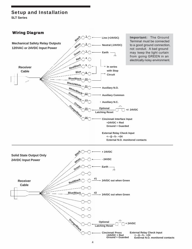
Important: The GroundTerminal must be connectedto a good ground connection,not conduit. A bad groundmay keep the light curtainfrom going GREEN in anelectrically noisy environment.
WWWWWiring Diairing Diairing Diairing Diairing Diagggggrrrrramamamamam
ReceiverCable
Black
White
Green
Red
Red/Black
Blue
Blue/Black
Black/WhiteWhite/BlackGreen/Black
OrangeOrange/Black
Line (+24VDC)
Neutral (-24VDC)
Earth
In series
with Stop
Circuit
Auxiliary N.O.
Auxiliary Common
Auxiliary N.C.
Optional
Latching Reset
Cincinnati Interface Input+24VDC = RedGround = Guarded
External Relay Check Input<---||---\\-- +24External N.O. monitored contacts
+/- 24VDC
Solid State Output Only
24VDC Input Power
ReceiverCable
Black
White
Green
Red/Black
Blue/Black
Orange/Black
+ 24VDC
- 24VDC
Earth
Optional
Latching Reset
Cincinnati Press+24VDC = RedGround = Guarded
+ 24VDC
#1
#2
24VDC out when Green
24VDC out when Green
External Relay Check Input<---||---\\-- +24External N.O. monitored contacts
4
5
9
10
11
12
13
15
16
1
2
7
Mechanical Safety Relay Outputs
120VAC or 24VDC Input Power

5
SLT Series
PylonsPylonsPylonsPylonsPylonsThe Emitter and Receiver pylons are mirror images; the obvious difference isthat there are no lights, keyswitch, or diagnostics display on the Emitter pylon.
“Dimension B”“Dimension A” Mounting Hole to
Model Enclosure Length Guarded Area Hole DimensionsSL-12 20.60” (523mm) 13.75” (349mm) 23.13” (588mm)SL-18 26.85” (682mm) 20.00” (508mm) 29.11” (739mm)SL-24 33.10” (841mm) 26.25” (667mm) 35.36” (898mm)SL-30 39.35” (999mm) 32.50” (826mm) 41.61” (1057mm)SL-36 45.60” (1158mm) 38.75” (984mm) 47.86” (1216mm)SL-42 51.85” (1317mm) 45.00” (1143mm) 54.11” (1374mm)SL-48 58.10” (1476mm) 51.25” (1302mm) 60.36” 1533mm)
Dimensional Information

6
SLT Series
AAAAAuto Blank uto Blank uto Blank uto Blank uto Blank (patented)Important: Place Auto Blank keyswitch into OFF/RESET position and remove any obstructionswhile aligning light curtain. Do not use AutoBlank until light curtain is correctly aligned(see Installation Procedure).
The keyed lock switch is designated to besupervisory controlled. After installation, the safetykey should be removed and controlled only by thesafety supervisor or authorized plant personnel.
The term Auto Blank is an abbreviation which stands forautomatic programmable beam blanking. Auto Blankingis controlled by a multi-position keyswitch and has threedistinct modes of operation:
1) MUST BE RESET IF AUTO BLANK OBSTRUCTION
MOVES OR GUARD PENETRATED
The Auto Blank obstruction must remain in itsexact location permanently. Any movement inthe Auto Blank obstruction and/or additionalguard penetration will latch the light curtain in aRED condition and must be reset via thekeyswitch.
NOTE: If no obstructions were programmed in,the guard will still latch in a RED condition shouldthe guard be penetrated.
2) MUST BE RESET IF AUTO BLANK OBSTRUCTION
MOVES.
The Auto Blank obstruction must remain in itsexact location permanently. This works likeMode 1 except guard penetrations will not latchrelays (automatic reset to GREEN condition).
3) MODE 2 WITH FLOATING BLANK
This mode works like Mode 2 with the additionof a Floating Blank which is set to allow a onebeam float (see Floating Blank).
NOTE: If no obstructions were programmed in,the guard will still allow a one beam float.
Do not place the moving obstruction in the lightcurtain while programming Auto Blank.
The Penetration Depth Factor D(pf) must be set toaccount for the one beam float plus Auto Blank (seeANSI Standard B11.19-2003 D(pf) table, Appendix A).
NOTE: On all modes of auto blanking, Auto Blankobstruction(s) need not be sequential, multipleobstructions can be programmed in at one time, but not
exceed a total of eight beams. The Diagnostics Displaywill issue a Code 8 if the Auto Blank obstruction(s) ismoved or exceeded the maximum allowable number ofobstructed beams.
Programming. Turn the keyswitch into the OFF/RESETposition and place the obstruction(s) in the guarded area.Turn the keyswitch into the desired mode of operation.You will notice that the Diagnostics Display will changeto show you the total number of beams currently beingblocked by the obstruction(s). This display will last forabout two seconds. If an obstruction was detected, thedisplay will issue a Code 7 to indicate that it has beenprogrammed into memory. Keep Auto Blank off untilthe light curtain is properly aligned and the unit is GREENwhen there are no obstructions.
AAAAAuxiliaruxiliaruxiliaruxiliaruxiliary Output Contacty Output Contacty Output Contacty Output Contacty Output ContactThe Auxiliary Output Contact feature provides either aN.O. or N.C. isolated (DRY) contact output to signal aRED condition on the light curtain. This output is usedin conjunction with the standard pair of output relaysthat get wired up to the safety circuit of your equipment(i.e., stop circuit). The standard relay output is monitored,but the Auxiliary Output Contact is NOT monitoredand should only be used as a signal line (i.e., foradditional PLC monitoring).
The Auxiliary Output Contact can handle 4 AMPS @120VAC (not fused). S pecify either N.O. (RED whenopen) or N.C. (GREEN when open) (see WiringDiagram).
CincinnaCincinnaCincinnaCincinnaCincinnati Interfti Interfti Interfti Interfti Interfaceaceaceaceace*The Cincinnati Interface feature allows an external device(i.e., Cincinnati Press, or PLC) to override the light curtainand initiate a RED condition and open up the standardoutput relay contacts. This is provided to allow a PLC todetermine if the light curtain is still capable of shuttingdown the safety control circuit.
The external device must provide a 24VDC output tothe light curtain to initiate this RED condition. If youhave this option, but for some reason do not use it,you must ground the interface terminal. Failure todo so could cause the guard to stay in a RED condition(see Wiring Diagram).
Features
* Although this option is standard, it must be requested at time oforder and cannot be used in conjunction with the External RelayCheck.

7
SLT SeriesFeatures
ExterExterExterExterExternal Rnal Rnal Rnal Rnal Relaelaelaelaelay Checy Checy Checy Checy Check*k*k*k*k*The External Relay Check feature allows the SLT Seriessystem to monitor an external relay using the externalrelay’s secondary set of isolated contacts, provided thatthey are N.O. captive contacts. This captive contact willmaintain the identical position as the primary set ofcontacts on the external relay . The External RelayContact must be opened when the light curtain is in aRED condition. Failure of the External Relay Contactwill show up on the Diagnostics Display as a Code 6. Ifthis failure lasts longer then one second, the light curtainwill lock up and must be powered down to clear the code(see the Wiring Diagram).
FFFFFloaloaloaloaloating Blankting Blankting Blankting Blankting BlankImportant: Place the Floating Blank keyswitchinto the 2cm position and remove any obstructionswhile aligning light curtain. Do not use FloatingBlank until light curtain is correctly aligned (seeInstallation Procedure).
The keyed lock switch is designated to besupervisory controlled. After installation, the safetykey should be removed and controlled only by thesafety supervisor or authorized plant personnel.
The Floating Blank option is controlled by a multi-positionkeyswitch located on the Receiver Pylon providing theSLT Series system the cap ability of blanking out anybeam. The keyswitch allows gaps of either 2cm (nobeams blocked), 4cm (one beam blocked), 6cm (twobeams blocked), or 8cm (three beams blocked) in thelight curtain. This permits the work piece to be passedthrough the guarded area and move around as long asthe number of blocked beams does not exceed thekeyswitch position set. The beams do not have to beblocked adjacent to one another.
Location of the light curtain from the point ofoperation must include the Depth Penetration FactorD(pf) equivalent to the beam spacing.
Floating Blank Worst Case D(pf)Keyswitch Minimum PenetrationPosition Object Sensitivity Factor
2cm (0 beams) 1.25" / 2.00" 3.5" / 6.0"4cm (1 beam) 2.00" / 3.50" 6.0" / 11.0"6cm (2 beams) 2.75" / 5.00" 8.5" / 16.0"8cm (3 beams) 3.50" / 6.50" 11.0" / 21.0"
LaLaLaLaLatctctctctching Rhing Rhing Rhing Rhing Relaelaelaelaelaysysysysys(standard on Perimeter guards)
The Latching Relays option causes the light curtain tolatch in a RED condition after a RED condition isencountered (penetration). The display reads “8”. Thisis used for guarding an area against intrusion, otherwise,without this option the light curtain would only stay REDas long as the intrusion was blocking the light curtains’field of view. A push button is used to reset the curtainand the software requires that the button be cycled byclearing the curtain.
To Install: Find the correct color wire from the Receivercable (see Wiring Diagram). Install a N.O. push buttonbetween the orange wire and +24VDC.
P101 should have a plug installed already. Remove thisplug and you will de-activate the latching relay feature.This allows you to align the curtain. Put back the plugwhen you are finished aligning the curtain.
U204 is where you hook up your reset button to the outerpins 1 & 4.
* Although this option is standard, it must be requested at time oforder and cannot be used in conjunction with the CincinnatiInterface.

8
SLT Series
Accessories
CorCorCorCorCornering Mirnering Mirnering Mirnering Mirnering MirrrrrrorororororsssssThrough the use of cornering mirrors, multiple sides orwork envelopes can be guarded which enhance safetyand reduce down-time related to mechanical andelectrical interlock systems.
Include a 5% reflectivity loss per mirror whencalculating total scanning distance of light curtain.
NOTE: Mirrors are surface coated. Wipe surface usingonly a damp, clean, soft 100% cotton cloth. To replace:remove the end bracket, slide out the mirror with thegasket.
Dim A Dim B Dim CModel (Hole to Hole) (Mirror) (Total)TRM12 19.45" (494mm) 18.25" (464mm) 20.50" (521mm)TRM18 25.45" (646mm) 24.25" (616mm) 26.50" (673mm)TRM24 31.45" (799mm) 30.25" (768mm) 32.50" (825mm)TRM30 37.45" (951mm) 36.25" (921mm) 38.50" (978mm)TRM36 43.45" (1104mm) 42.25" (1073mm) 44.50" (1130mm)TRM42 49.45" (1251mm) 48.25" (1226mm) 50.50" (1282mm)TRM48 55.45" (1408mm) 54.25" (1378mm) 56.50" (1435mm)TRM60 67.45" (1713mm) 66.25" (1683mm) 68.50" (1739mm)TRM72 79.45" (2018mm) 78.25" (1988mm) 80.50" (2045mm)
PPPPPedestal Mounts (Model 8000)edestal Mounts (Model 8000)edestal Mounts (Model 8000)edestal Mounts (Model 8000)edestal Mounts (Model 8000)The heavy duty, all welded steel pedestal floor mountscan be used for mounting either the SLT Series systemor cornering mirrors. Sliding mounts on the pedestalare of universal design and are supplied standard.Unique floating base on pedestal is designed tocompensate for uneven floors.
Pedestals must be bolted to the floor, they must notbe movable!
1) Sliding Mounts supplied
2) Standard height - 72" - Model 8000Optional height - 96" - Model 8096
3) Painted OSHA yellow
4) Pedestal - 12 gauge steelBase Plate - 1/4" steel plate

9
SLT SeriesAccessories
Swing-ArSwing-ArSwing-ArSwing-ArSwing-Arm Mounting Brm Mounting Brm Mounting Brm Mounting Brm Mounting Bracacacacackkkkketetetetet(Model 9000)(Model 9000)(Model 9000)(Model 9000)(Model 9000)Excellent method of mounting light guard for pressbrakes or when light guard is to be moved for die setupsor machine maintenance. Model 9000 consists of three180° pivot points along with light guard diagonalmovement capability for virtually unlimited light guardpositioning. Two inch square tubing 3/16" thick paintedOSHA yellow which mounts directly onto the machinehousing and makes for a heavy duty yet versatilemounting bracket.
Specify dimensions “B” & “C”

11
SLT SeriesDiagnostics and Troubleshooting
DiaDiaDiaDiaDiagnostic Indicagnostic Indicagnostic Indicagnostic Indicagnostic Indicator Lightstor Lightstor Lightstor Lightstor LightsEmitter Pylon. The Sync Channel light is located onthe Emitter Pylon and is visible 11 1/2 inches down fromthe top of the enclosure inside the pylon (it cannot beviewed from outside the pylon, the cover must be takenoff). The normal condition of this light is out. It willilluminate only if the top channel is blocked or not linedup, and briefly for a 1/2 second at the time power isapplied to both pylons.
There are internal indicator lights located inside at thetop of the Emitter Pylon to indicate proper internalvoltages. These are:
1) GREEN - 12VDC
2) RED + 12VDC
3) AMBER + 10VDC
All three lights must be illuminated for proper systemoperation.
Receiver Pylon. There are internal LED’s on the bottomof the power supply board next to both safety relays toindicate if they are energized or not. There are alsothree LED’s on the top receiver board (1/3rd of the waydown the board) to indicate proper voltages. These are:
1) GREEN + 12VDC
2) RED + 12VDC
3) AMBER + 5VDC
All three lights must be illuminated for proper systemoperation.
Slave Microprocessor. Four more LED’s are locatedinside at the very top of the upper printed circuit board inthe Receiver Pylon, these indicators explain the conditionof the Slave Microprocessor. These are:
1) GREEN OK
2) YELLOW Blocked DATA CHANNEL
3) RED External fault (slavedetected a fault)
4) RED Internal fault (slavemicroprocessor is bad)
You may notice flickering in these LED’s, this is becausethe slave is much faster than the system it is monitoring.
If either RED LED stays lit, then a fault occurred and theunit must be checked out.
TTTTTrrrrroubouboubouboubleshootingleshootingleshootingleshootingleshootingNOTE: When light curtain is powered up, theDiagnostics Display will count down four times with thedecimal points on. This indicates that themicroprocessors are functioning correctly. If you do notsee this happening, your light curtain unit must bereturned for repair.
PROBLEM: Light curtain locks up / light curtainresets when penetrated.
Cause(s): 1) Check line voltage on the inputpower terminals and make surethat it is within this units’specifications. Low voltage cankeep the output relays from closingand will keep the guard in a REDcondition and/or cause themicroprocessors to keep resetting.
2) Check the voltage level on theoutput relay contact terminals—itshould not exceed 130V AC. Ahigher voltage will cause theinternal MOV noise filtering devicesto short to ground when the outputrelay contacts close which willcause the unit to lock up in a REDcondition.
3) Check for noise on lines at thepower terminals and/or output relayterminals. Dirty line voltage cancause the microprocessors to resetand/or the unit to lock up in a REDcondition.
Cure(s): 1) If line voltage is low, you must finda way to boost the voltage level.
2) The manufacturer will provide youwith MOV components which youcan then place on the power linesof any device that may be causingnoise on the line voltage (i.e.,Solenoids, motors, etc.)
PROBLEM: Light curtain gets a code “C” on thedisplay or sometimes won’t goGREEN.
Cause(s): Examine the locations of all lightcurtains around the troubled unit. Whenone unit can see another unit (i.e.,Receiver Pylon of unit 1 can see EmitterPylon of unit 1 as well as Emitter pylon
10

12
SLT Series
Diagnostics and Troubleshooting
of unit 2), synchronization betweenEmitter and Receiver pylons is broken.The light curtain will either display acode “C” upon power up, or stay in aRED condition.
Test: Run troubled light curtain with other lightcurtains (in view) turned of f. Thetroubled light curtain should now workcorrectly.
Cure(s): a) Try re-adjusting the locations of alllight curtains. A slight tilt of a pyloncan clear up the problem.
b) Put up partitions or blindersbetween light curtains.
PROBLEM: Light curtain does not go GREEN.
Cause(s): Many.
Test: Try running the unit with the pylonsbutted up against each other. The unitshould now go GREEN. If it doesn’t,the unit should be returned for rep air.If it went GREEN, the beams may bemis-aligned. You may be running theunit beyond its aligned distance. Thereis a 5% penalty for every mirror you use.
Cures: Both pylons may require slightadjustments even after beingmechanically aligned to get the unit togo GREEN. The SLT Series systemuses infrared light emitting diodes(IRLED’s) as a means of detectingobstructions found in the field of viewbetween the two pylons. TheseIRLED’s are spaced at regular intervalsdown the entire length of the curtain.The infrared light fans out like aflashlight beam, not like a laser beam.As the infrared light fans out, it losesstrength, so the farther apart the lightcurtain pylons are, the weaker thesignal. Proper mechanical alignmentof the pylons should allow the lightcurtain to function properly. However,some problems can still occur, but canbe cleared up upon further explanation.They are as follows:
Connections. Check for properconnections and voltage levels beforeproceeding further.
Vibration. The SLT Series systemallows for a certain amount ofmechanical play once aligned, butsometimes the units are installed somovement in a particular direction willcause the unit to go RED. Over a periodof time, vibration may cause themounting brackets to shift slightly andin some cases the unit may becomemisaligned to the point that it will not goGREEN anymore. To determine this,loosen up the mounts and re-adjustboth pylons one at a time until the unitgoes GREEN. If you have mirrors, youmay have to re-adjust them too.
Obstructions: Look for objects that areclose to or in the field of view of thelight curtain. Once you havedetermined a location to mount yourlight curtain, you must be careful ofnearby obstructions (objects that arenot mechanically in the line of sight ofthe light curtain pylons but fall withinabout 1/2 inch). Although these objectsmay not be mechanically in the line ofsight, the light curtain may fail to goGREEN because it detected the objectas an obstruction. The reason for thisis because the nearby obstructionreduces the amount of infrared light thatgets by the object and the ReceiverPylon fails to see the beam and staysRED.
Use of Mirrors. The use of mirrors togo around corners creates a penalty indistance and adjustment play. Whenyou use mirrors, some of the infraredlight passes through the surface coatingof the mirror. This decreases the totaldistance the light curtain can go (about5% per mirror). If the mirror was notsurface coated, the loss would be evengreater and parallax view would makeit very difficult to align.
Upon determining the location of themirrors, you must allow for someadjustment. Because angle ofincidence equals angle of reflection, asmall error in location of any mirror willthrow off the beams as they pass to thenext mirror and may be compoundedwhen passed again to a third mirror .Even though you may have determined
11

13
SLT SeriesDiagnostics and Troubleshooting
that mechanically the beams should behitting the center of the mirror , thebeams may hit the next mirror slightlyoff center due to inaccuracies betweenthe optical and mechanical centers.
Once the mirrors and pylons are placedin mechanical alignment, start adjustingthe mirror closest to the Emitter Pylon.This will af fect the location that thebeams strike the next mirror, and so on.
Nearby obstructions may fall into thefield of view if the mirrors are notcorrectly adjusted.
Other Light Curtains. The infraredbeams that leave the Emitter Pylonspread out like a flashlight andsometimes may end up hitting theReceiver Pylon of another pair of lightcurtains. This can sometimes throw offboth sets of light curtains and keep oneor both sets RED.
To determine if this is happening, turnoff all light curtains and try one set at atime. You may have to place a blinderto keep one unit from seeing another.
Reflections. Highly reflective materialnear the light curtain can cause theinfrared light to bounce around andkeep the unit RED. To determine if thisis happening, temporarily cover up anyreflective material (i.e., polished metal)and re-align the pylons and the unitshould go GREEN. You have to paintthe offending object to clear up theproblem.
DiaDiaDiaDiaDiagnostic Displagnostic Displagnostic Displagnostic Displagnostic Display Codesy Codesy Codesy Codesy Codes.1. Blinking .... If the decimal points on the display are
blinking, this indicates that thecomputers have not received a singlebeam from the Emitter Pylon. Thismeans that either the Emitter Pylon isnot on, you are blocking the sync (top)channel, a bad Emitter Pylon, or analignment problem.
0 ..................... Clear
Definition: No obstructions found.
Status: GREEN, output relays energized.
Reason: Nothing wrong.
1 ..................... 1 Beam Broken/Alignment Problems
Definition: The light guard was triggered when atleast one beam was detected broken.
Status: RED, fail safe relays off.
Reason(s): 1) Obstruction of one or more beamsduring normal light curtainoperations. Floating Blank option:set to 2cm mode.
2) If no obstruction is observed, thenlight curtain is misaligned.
3) Emitter Pylon is not transmitting.
4) Sync Channel not firing.
Cure(s): 1) Remove all obstructions.
2) Place Floating Blank option in 2cmmode.
3) Place Auto Blank option in OFF/RESET position.
4) If the Sync LED is of f and thedisplay still reads 1, then try andrealign the light curt ain’s positionuntil you get a GREEN condition.
5) If the Sync LED is on, then tryaligning the pylons to get the SyncLED to go out. Placing the pylonsclose together will prove if the unitswill ever go GREEN.
Important: The Ground Terminal must beconnected to a good ground connection, notconduit. A bad ground may keep the light curtainfrom going GREEN in an electrically noisyenvironment.
12

14
SLT Series
Diagnostics and Troubleshooting
2 ...................... 2 Beams Broken
Definition: The light guard was triggered when atleast two beams were detected broken.
Status: RED, fail safe relays off.
Reason(s): Floating Blank option: set to 4cm mode.
a) If no obstruction is observed, thenlight curtain is misaligned.
b) Emitter Pylon is not transmitting.
Cure(s): Remove all obstructions. If display stillreads 1 or 2, then realign light curtainwith the Floating Blank option in 2cmmode or the Auto Blank option in OFF/RESET position (see InstallationProcedure, Page 3).
3 ...................... 3 Beams Broken
Definition: At least three beams were detectedbroken.
Status: RED, fail safe relays off.
Reason(s): Floating Blank option: set to 6cm mode.
a) If no obstruction is observed, thenlight curtain is misaligned.
b) Emitter Pylon is not transmitting.
Cure: Remove all obstructions. If display stillreads 1, 2, or 3, then realign light curtainwith Floating Blank option in 2cm modeor Auto Blank option in OFF/RESETposition (see Installation Procedure,Page 3).
4 ...................... 4 Beams Broken
Definition: The light guard was triggered when atleast four beams were detected broken.
Status: RED, fail safe relays off.
Reason(s): Floating Blank option: set to 8cm mode.
a) If no obstruction is observed, thenlight curtain is misaligned.
b) Emitter Pylon is not transmitting.
Cure(s): Remove all obstructions. If display stillreads 1, 2, 3, or 4, then realign lightcurtain with Floating Blank option in2cm mode or Auto Blank option in OFF/RESET position (see InstallationProcedure, Page 3).
5 ...................... Relay Fault: One On / One Off
Definition: There are two captive contact relaysinside the light curtain of which one isopen and the other is closed. Thiscondition should never occur becausethe system is designed to alwaysoperate both relays together.
Status: Both the RED and GREEN lights areon but the output circuit is broken andthe light curtain has failed safe.
Reason(s): a) Contact on one relay weldedtogether keeping it closed or otherinternal mechanical relaymalfunction.
b) Fault in one of the driver IC’ scausing either a relay to remain onor off.
c) Jumper settings on watchdog timerIC’s are incorrectly set.
d) Fault in one of the two watchdogtimers controlling the driver IC’ swhich require a clock signal of aperiod less then 1 mSEC.
e) Fault in the gate chip between theMaster and Slave computers whichallows the Slave computer tooverride the Master and turn a relayon.
f) Error condition exists within one ofthe two computers.
g) The two computers disagree onwhether to turn the relays off.
h) Line voltage levels too low toactivate one of the two relays.
Cure(s): Only reason a) can be checked by user,all other reasons can only be checkedby authorized trained personnel.
6 ...................... Relay Fault: Both off (should be on)
Definition: Both relays were detected as OFFwhen they were signalled by thecomputer to turn on.
Status: Red light on, fail safe.
Reason(s): a) Internal mechanical relay problem.
b) Jumpers on watchdog timer IC’ sare incorrectly set.
13

15
SLT SeriesDiagnostics and Troubleshooting
c) Slave has legally overridden theMaster because it believed thecurrent conditions require therelays to be off.
d) Line voltage levels too low toactivate either relay.
Cure(s): Only reason a) can be checked by user,all other reasons can only be checkedby authorized trained personnel.
7 ...................... Auto Blank Activated
Definition: The Auto Blank keyswitch was movedfrom the OFF/RESET position into anAuto Blank position and an objectcovering a total of less then nine beamswas found. Before Code 7 is displayed,the display will show the exact numberof blocked beams for about twoseconds (see Auto Blank section underOptional Features, Page 5).
Status: GREEN light on, relays closed.
Reason(s): An obstruction was placed in the fieldof view of the light curtain and wassubsequently programmed into thecomputer via the keyswitch.
Cure(s): To deactivate the Auto Blank, turn thekeyswitch back into the OFF/RESETposition or power down the light curtainto clear the memory.
8 ...................... Auto Blank Obstruction Missing
Definition: After Auto Blank was activated, theobstruction was moved from its initialposition in the guarded area or theobstruction was too big.
Status: GREEN in Auto Fixed Blank mode
RED in the other two Auto Blank modes(see Auto Blank section under OptionalFeatures, Page 5).
Reason(s): a) The user activated the Auto Blankand subsequently moved theobstruction from its programmedposition.
b) The total obstruction size exceededeight beams.
Cure(s): a) Re-adjust the obstruction positionand stabilize its movement.
b) Make sure the total size does notexceed eight beams.
9 ...................... Internal Ram Fault
Definition: When the light curtain self-tests, itexercises all of its internal ram locationsto make sure that they all store dataproperly. Upon testing, one or morememory locations failed this test.
Status: RED light, fail safe relays open.
Reason(s): a) Reset circuitry failed to respond toa glitch in the power supply line.
b) Bad ram.
c) Bad ground.
Cure(s): Check grounds, power down the lightcurtain for one minute and try again. Ifthis does not work, the unit must beserviced by authorized personnel.
A...................... Master cannot talk to slave computer
Definition: The Master waits for the Slave tocommunicate between each scan of thelight curtain and will time-out if it can’tcomplete its communication.
Status: RED light, fail safe relays open.
Reason(s): a) Faulty microprocessor chip(s).
b) Noise on power line causes one ofthe two microprocessors to resetand fall out of sync with the other.
c) Intermittent drop in line voltage.
Cure(s): If the problem is intermittent, then it isnoise. Tap power for the Receiver Pylonhead of all other devices that causenoise (i.e., solenoids, motors) so that itgets cleaner power. Also, monitor linevoltage for any intermittent drops.
B...................... Data disagreement with the slaveunit
Definition: The Master has linked up with the slaveproperly, but the Slave sees dif ferentdata then the Master.
14

16
SLT Series
Diagnostics and Troubleshooting
Status: RED light, fail safe relays open.
Reason(s): a) information on switch positionsdiffer.
b) values of special registers differ.
Cure(s): Check ground connections. The unitmust be serviced by authorizedpersonnel.
C...................... External infrared source detected atstartup
Definition: Infrared signals detected when the rightside Emitter Pylon was not signaled totransmit.
Status: RED light, fail safe relays open.
Reason(s): External pulse of infrared light from astrobe or another light curtain wasdetected during self-testing.
Cure(s): Turn off all other light curt ains in theentire area and try the curtain again. Itis probably another nearby light curtainemitter throwing this light curtain out ofsync. You may need to reverse theirposition by exchanging the Receiverand Emitter pylon with each other so itfires its beams in the other direction.
D...................... Internal Short/Open
Definition: Between each scan the Master looksat the output of each receiver circuit inturn. Should an improper signal leveloccur, this code is displayed.
Status: RED light, fail safe, relays open.
Reason(s): a) Problem in any one of the cableconnections inside the ReceiverPylon.
b) Short in one of the phototransistors.
c) Open in one of the comparators.
d) External infrared source of longduration.
e) Beam in transmitter pylon left on.
Cure(s): Check all cables inside the ReceiverPylon for bent pins or cold solder joints.
E ...................... Beam and/or board select line failure
Definition: The Master has linked up with the slaveproperly, but the Slave sees dif ferentdata then the Master.
Status: RED light, fail safe relays open.
Reason(s): a) Board select chip bad.
b) Beam select chip bad.
c) Master has problem with data portselect lines.
d) Slave has problem with readingselect lines.
e) Short or open on PCB.
Cure(s): Check ground connections. The unitmust be serviced by authorizedpersonnel.
F ...................... Clock/Code Failure
Definition: The onboard watchdog timer sensed aclock malfunction or a failure in theexecution of the code. Upon initialpower up, the Diagnostic Display shouldcount backwards from ‘.F .’ to ‘.0.’ toindicate that its clock is running. If youdo not see this happening whenpowering up, the clock or computer chipis bad. If you see it happen and thenget this code, a glitch has caused asoftware code failure.
Status: RED light, fail safe relays open.
Reason(s): a) Voltage levels too low for operation.
b) Crystal bad.
c) Power surge caused code toexecuted improperly.
d) Reset circuit glitch.
e) Computer bad.
Cure(s): Check for low line voltage. If the linevoltage drops below 105VAC (even forjust a second) the guard could lock upand display this code.
15

17
SLT SeriesDiagnostics and Troubleshooting
Diagnostic Display decimal points light up when theAuto Blank (optional feature) keyswitch is moved fromthe OFF/RESET position into an Auto Blank modeposition. This is to show the user how many beams theAuto Blank obstruction is blocking. This display will lastfor about two seconds while the computer ’s areprogramming in the obstruction.
Display Definition
.0. No beams blocked
.1. 1 beam blocked
.2. 2 beams blocked
.3. 3 beams blocked
.4. 4 beams blocked
.5. 5 beams blocked
.6. 6 beams blocked
.7. 7 beams blocked
.8. 8 beams blocked
The following display codes exceed the maximumallowed blocked beams for Auto Blank.
.9. 9 BEAMS BLOCKED
.A. 10 BEAMS BLOCKED
.B. 11 BEAMS BLOCKED
.C. 12 BEAMS BLOCKED
.D. 13 BEAMS BLOCKED
.E. 14 BEAMS BLOCKED.F. 15 OR MORE BEAMS BLOCKED
16

A-1
Appendix A:Regulations & Guidelines for Safe Operation
SLT Series
ANSI StandarANSI StandarANSI StandarANSI StandarANSI Standard B11.19-2003d B11.19-2003d B11.19-2003d B11.19-2003d B11.19-2003FFFFFororororormmmmmula fula fula fula fula for calculaor calculaor calculaor calculaor calculating safting safting safting safting safetyetyetyetyetydistance ofdistance ofdistance ofdistance ofdistance of light cur light cur light cur light cur light curtains frtains frtains frtains frtains fromomomomomhazarhazarhazarhazarhazardous point ofdous point ofdous point ofdous point ofdous point of oper oper oper oper operaaaaation.tion.tion.tion.tion.The effective sensing field of the device shall be locatedat a distance from the nearest recognized hazards suchthat the operator or others cannot reach the hazard with ahand or other body part before cessation of motion duringthe hazardous portion of the machine cycle.
The point at which a device responds to an intrusion mayvary. The devices should be located or adjusted such thatthe device always responds to the intrusion at or prior tothe safety distance. Care should be exercised wheninstalling the device to ensure that it does not detect falsesignals from other devices in the area.
Usually the electro-optical presence-sensing device is usedin a manner that provides a protected zone in front of theprimary work area with auxiliary devices or guards usedto protect secondary access areas. In some cases,however, mirrors may be used in conjunction with thedevice to provide 2-, 3-, or 4-sided protection.
The machine stop time should be measured with themachine running at its fastest speed with its heaviest dieor tooling and the stop time being measured at the 90°position in the downstroke.
The following formula should be used when calculatingthe safety distance:
Ds = K x (Ts + Tc + Tr + Tbm) + D(pf)
Ds = Minimum safety distance between thedevice and the nearest point of operationhazard (in inches).
K = Hand speed constant. This value has beendetermined by various studies and, althoughthese studies indicate speeds of 63 in/sec toover 100 in/sec, they are not conclusivedeterminations. The employer shoulddetermine this value by considering all factors,including physical ability of the operator.
Ts = Stop time of the machine tool measured by astop time measurement device.
Tc = Response time of the control system (usuallyis taken care of by the measurement device).
Tr = Response time of the presence-sendingdevice and it’s interface, if any, as stated bythe manufacturer or measured by theemployer.
Tbm = Additional time allowed for the brake monitorto compensate for variations in normalstopping time.
D(pf) = Depth Penetration Factor. Added distance asindicated by Figure 2. The minimum objectsensitivity is stated by the manufacturer. If aFloating Blank is used, use the Dpf numbersfound on Tables 2 and 3.Figure 2: Minimum Object Sensitivity and D(pf)
MinimumObject
Sensitivity,S
Penetration factor, Dpf, for presence-sensingdevices used in a vertical application with objectsensitivity less than 64 mm (2.5 inches)
Dpf, the distance added to the safety distance due tothe penetration factor compensates for varying objectsensitivities of electro-optical presence-sensingdevices.
When blanking features are used and when theblanked area is not completely filled by the workpieceor part, or by mechanical guarding, the minimumobject sensitivity can be calculated as:
Object sensitivity = size of the blanked area plusminimum object sensitivity without blanking.
Once this value is found, then determine Dpf.
If the entre blanked area is filled with mechanicalguarding or other fixed material or guards, use thedevice’s object sensitivity to determine Dpf.
Dpf = 3.4 (S-7) mm(Dpf = 3.4 (S-0.275) in)

A-2
Appendix A:Regulations & Guidelines for Safe OperationSLT Series
Light CurLight CurLight CurLight CurLight Curtain tain tain tain tain TTTTTest Prest Prest Prest Prest ProcedurocedurocedurocedurocedureeeeeUse a dowel rod (or similar object) with a diameter equalto the M.O.S. (Minimum Object Sensitivity) of the guardyou are testing. Move the rod through the field of thecurtain (i.e. top to bottom for vertically mounted cur-tains). Repeat this test close to the Emitter pylon, closeto the Receiver pylon, in the middle between the py-lons, and most importantly in front of the operator posi-tion.
Make sure the curtain indicates a “Blocked” condition(RED light) when the rod is in the field of the curtain.
Check and make sure the machine cannot move whenthe curtain shows “Blocked”. If the machine can oper-ate while the curtain shows a “Blocked” condition, thenre-examine your wiring.
NOTE: Always use both safety relays in your ST OPcircuit(s).
If the curtain does not show “Blocked” when the rod isin the field: Check to make sure the rod is truly in thecurtain’s field, and re-check the curtain’s Minimum Ob-ject Sensitity (including AutoBlank and Floating blankoptions that change the M.O.S.).
Infrared light from the curtain may be reflecting aroundthe rod due to reflective material too close to the curtain’sfield. In this case, you will have to move the curt ainpylons back away from the reflective material and re-peat the test over again. The curtain’s power level canalso be reduced by the factory.

A-3
Appendix A:Regulations & Guidelines for Safe Operation
SLT Series
SafSafSafSafSafeeeeeguarguarguarguarguarding with Mecding with Mecding with Mecding with Mecding with MechanicalhanicalhanicalhanicalhanicalGuarGuarGuarGuarGuardsdsdsdsdsWhen a light system is used to protect the operator orpasserby from penetration, it must be mounted andproperly sized (grid length) so it is impossible to reachunder, around, or over into the hazardous point ofoperation zone. Infrared light systems normally guardthe front or feed area of a machine. The sides or theareas where the light screen does not guard must beguarded by some other means.
If the position of the safety light curt ain will allow theoperator or others to place themselves between thesensing field and the hazardous area, auxiliary guardsor devices such a safety mats, barrier guards or devicesshould be used in conjunction with the safety light curtainto prevent the operator or others from exposure to thehazardous area.
If mechanical guards such as: polyurethane, expandedor perforated metal, hairpins, etc. are used to guard theseareas, the opening must comply with the OSHA safetydistance in relationship to the openings.
After installation of point of operation guards and beforea job is released for operation, a check should be madeto verify that the guard will prevent the operators handsfrom reaching into the point of operation or any hazardzone.
Table 0-10: Mechanical GuardsDistance of opening from Maximum
point of operation width ofhazard (inches) opening (inches)
1/2 to 1-1/2 1/4
1-1/2 to 2-1/2 3/8
2-1/2 to 3-1/2 1/2
3-1/2 to 5-1/2 5/8
5-1/2 to 6-1/2 3/4
6-1/2 to 7-1/2 7/8
7-1/2 to 12-1/2 1-1/4
12-1/2 to15-1/2 1-1/2
15-1/2 to 17-1/2 1-7/8
17-1/2 to 31-1/2 2-1/8
The table above shows the distances that guards shouldbe positioned from the nearest point-of-operationhazards.
The various openings are such that for average sizehands, an operator’s fingers will not reach the point ofoperation.
After installation of point-of-operation guards and beforea job is released for operation, a check should be madeto verify that the guard will prevent the operator’s handsor other body parts from reaching the point of operation.

A-4
Appendix A:Regulations & Guidelines for Safe OperationSLT Series
OSHA ROSHA ROSHA ROSHA ROSHA Reeeeegulagulagulagulagulationstionstionstionstions1910.217 (C) (3) (iii)Safeguarding the Point of Operation
(iii) A presence sensing point of operation device shallprotect the operator as provided in paragraph (c) (3) (i)(a) of this section, and shall be interlocked into the controlcircuit to prevent or stop slide motion if the operator ’shand or other part of his body is within the sensing fieldof the device during the downstroke of the press slide.
(a) The device may not be used on machines usingfull revolution clutches.
(b) The device may not be used as a tripping meansto initiate slide motion.
(c) The device shall not be constructed so that afailure within the system does not prevent thenormal stopping action from being applied tothe press when required, but does prevent theinitiation of a successive stroke until the failureis corrected. The failure shall be indicated bythe system.
(d) Muting (bypassing of the protective function) ofsuch device, during the upstroke of the pressslide, is permitted for the purpose of partsejection, circuit checking, and feeding.
(e) Refer to ANSI B11.19-2003 for calculating safetylight curtain distance from the point of operation.
(f) Guards shall be used to protect all areas of entryto the point of operation not protected by thepresence sensing device.
1910.217 (C) (3) (iii)Additional requirements for safeguarding
Where the operator feeds or removes parts by placingone or both hands in the point of operation and a twohand control presence sensing device or Type B gate ormovable barrier (on a part revolution clutch) is used forsafeguarding:
(i) The employer shall use a control system and abrake monitor which comply with paragraphs(b) (13) and (14) of this section.
(e) Inspection, maintenance, and modification ofpresses-
(i) It shall be the responsibility of the employerto establish and follow a program of periodicand regular inspections of his powerpresses to insure that all their parts, auxiliary
equipment, and safeguards are in a safeoperating condition and adjustment. Theemployer shall maintain records of theseinspections and maintenance workperformed.
1910.212General requirements for all machines (covers pressbrakes, hydraulic and pneumatic machines notcovered by mechanical power press standards)
(a) Machine guarding - (1) Types of guarding. Oneor more methods or machine guarding shall beprovided to protect the operator and otheremployees in the machine area from hazardssuch as those created by point of operationingoing nip points, rotation parts, flying chips andsparks. Examples of guarding methods are:barrier guards, two-handed tripping devices,electronic safety devices, etc.
NOTE: These are only partial reprints, refer to yourFederal Register for total construction, control reliability,and machine guarding requirement s for the subjectmachine being guarded for all applicable OSHAStandards.

A-5
Appendix A:Regulations & Guidelines for Safe Operation
SLT Series
MacMacMacMacMachine Contrhine Contrhine Contrhine Contrhine Control Rol Rol Rol Rol ReliaeliaeliaeliaeliabilitybilitybilitybilitybilityRRRRRequirequirequirequirequirementsementsementsementsementsCONTROL RELIABILITY:
“...control circuits shall be designed and constructed sothat a single failure or fault within the system does notprevent the normal stopping action from being appliedto the press when required, or does not create anunintended stroking action, but does prevent initiationof a successive stroke until the failure is corrected.”(ANSI B11.1-1988)
“...control shall be designed to prevent initiation of astroke signal in the event that a failure occurs within thepress control.” (ANSI B11.2-1982)
“Robots shall be designed and constructed so that anysingle, reasonably foreseeable failure will not causehazardous motion of the robot.” (ANSI/RIA R15.06-1991)
“...control circuits shall incorporate features to minimizethe possibility of an unintended stroke in the event ofthe failure of the control component to function properly,including relays, limit switches, and static output circuits.”(ANSI B11.1-1982)
“...control system shall be constructed so that a failurewithin the system does not prevent the normal stoppingaction from being applied to the press when required,but does prevent initiation of a successive stroke untilthe failure is corrected.” (ANSI B11.1-1982)
“...the control system shall be constructed so that a failurewithin the system does not prevent the normal stoppingaction from being applied to the press when required,but does prevent initiation of a successive stroke untilthe failure is corrected.” (OSHA CFR 1910.217, 1988)
SafSafSafSafSafety Guidelines fety Guidelines fety Guidelines fety Guidelines fety Guidelines for Manaor Manaor Manaor Manaor ManagggggementementementementementOperational Safety
1. Appoint a Safety Coordinator to be responsiblefor safety regulations, requirements, andsuggestions. He must review and investigateall accidents and “close calls.”
2. Establish and issue safety rules. Inform eachemployee of his responsibilities. Make sure heunderstands them and knows what is expectedof him.
3. A thorough review and an early inspection mustbe made of existing presses, dies, and point ofoperation guarding to attain the degree ofresponsibility required by ANSI B11.1-1988
Safety Standards and Federal S tate laws.Review what mandatory modifications arenecessary.
4. Equipment that is no longer safe and that cannotbe economically upgraded should be destroyed.
5. Never allow persons legally under age tooperate or assist in the operation of machinery.
6. All personnel must be properly trained toeliminate accidents and injuries.
7. Regardless of the operator ’s experience,education or language barrier , it is theresponsibility of the supervisor to give him athorough explanation with each new jobassignment.
8. No employee should be given a workassignment that he does not fully understand.Only properly instructed and thoroughly trainedpersonnel should be assigned to work on or withany machine.
9. It shall be the responsibility of the employer toprovide an adequate, clean, safe anduncluttered work area around each machine.
10. If a malfunction is reported, stop the machineimmediately, correct the problem, then resumeproduction.
11. Investigate all accident s and close calls.Analyze the reason for occurrence. Take actionto prevent recurrence. Keep records of theinvestigation and preventative steps that weretaken.
12. Only employees who understand the machines,operation and safety requirements, and who areable to communicate this knowledge should begiven the responsibility of instructing and trainingothers to perform as operators.
13. Management must decide that personnelprotective safety equipment is required toperform each job safely. Items such as safetyglasses, shoes, gloves, helmets, hand pads,spats, protective sleeves, and material handlingequipment are common in the metal workingindustry. If noise levels are excessive, protectivehead sets and ear muffs are recommended.
14. When designing point of operation guarding, themanufacturing process should be weighedheavily in favor of operational safety.
15. Establish safe and convenient material handlingmethods and procedures.

A-6
Appendix A:Regulations & Guidelines for Safe OperationSLT Series
16. Post in convenient areas the names, addresses,and phone numbers of physicians and hospitals,and members of the organization who are to becalled in case of emergency.
17. All equipment must be electrically connectedaccording to the National Electric Code and beconsistent with other accepted practices.
18. Provide adequate and proper fire protectionequipment.
Power Press Guarding
1. Press manufactures do not know and cannotforesee the magnitude of potential applicationsof power presses. Therefore, only the pressuser can determine the type of guards that haveto be used in order to perform the job safely. Itis the responsibility of the user management tomake certain that point of operation guardingand other necessary safety devices are installed.The press should be guarded in such a mannerthat it is impossible for the operators to placetheir hands or any other part of the body in thedie area.
2. The press user should become thoroughlyacquainted with the safety devices commonlyemployed in power press operations.
3. Feeding devices are strongly recommended,since they remove the operator from the diearea, and therefore allow more ef fectiveutilization of guards and safety devices.
4. Do not release a press for production beforeinstalling and testing all guards and covers.
5. Make frequent evaluation checks of all guardingand devices while the press is running. Correctall unsafe findings immediately.
Power Press Care Through Inspection andMaintenance
1. All maintenance and inspection personnelshould be specifically instructed, and mustunderstand proper maintenance and inspectionprocedures contained in this manual.
2. Set up a daily , weekly, and monthly pressinspection program. Use a checklist and verifythat the job is done correctly.
3. Establish a preventative maintenance program.Records of all maintenance work performedmust be kept.
4. Since all equipment has a limited life, high qualitymaintenance personnel are required to obtainmaximum usage of your equipment.
5. Releasing a power press for production followingmaintenance should be the responsibility of aqualified individual assigned by management.
6. To maintain the original level of press reliability,careful inspection of mechanical, electrical, andpneumatic areas must be made. This may givean advance warning of a hazard which then canbe corrected to prevent possible injuries anddamage.
Safety Enforcement
In order to have an ef fective safety program,management at all levels must enforce every safety ruleand regulation. Strong disciplinary measures aresometimes required. They should consist of a warning,written reprimand, work suspension, transfer, demotion,or possibly a dismissal. All infractions must be reportedand recorded. Once an infraction is noted, it shows thatan unsafe practice or condition has existed. This maybe the result of poor planning or improper training andinstructing. The reason for the infraction should beanalyzed in order to take corrective action.
Supervisor Training
It should be the responsibility of management to instructtheir supervisors on safety , giving job instructions,supervising operators, determining accident causes, andbuilding safety attitudes among the press operators.Many accidents have occurred due to a supervisors lackof training.
Operator Training
It shall be the responsibility of management to insureproper training of operators. A specific training programshould be instituted to instruct the operator in safety ,proper usage of the equipment, and correct operationalprocedure in performing each and every job. In additionto the supervisor, the operator should be familiar withthe proper guarding of the point of operation. Neverpermit an operator to start a job without completeinstructions from his immediate supervisor.

WARRANTY
Manufacturer warrants that this product will be free from defects inmaterial and workmanship for a period of two years from the date ofshipment thereof. Within the warranty period, manufacturer will rep airor replace such products which are returned to it with shipping chargesprepaid and which will be disclosed as defective upon examination bythe manufacturer. This warranty will not apply to any product which willhave been subject to misuse, negligence, accident, restriction, and usenot in accordance with manufacturer ’s instructions or which will havebeen altered or repaired by persons other than the authorized agent oremployees of the manufacturer.
DISCLAIMER
The provisions of the paragraph “Warranty” are the sole obligations ofthe manufacturer and exclude all other warranties of merchant ability,expressed or implied.
Further, there are no warranties which extend beyond the above warranty.
LIMITATION OF LIABILITY
In the event of any claim or breach of any obligations of manufacturerunder any order, whether expressed or implied, and p articularly in theevent of any claim or a breach of the warranty or warranties containedin the paragraph “Warranty” or of any other warranties, expressed orimplied which might, despite the p aragraph entitled “Disclaimer,” bedetermined to be incorporated in any order , the company shall underno circumstances be liable for any consequential or special damages,either in law or in equity , or for losses or expenses or claims for thesame arising from the use of, or inability to use, the products of themanufacturer for any purpose whatsoever.
WARNING: The entire machine safety system must be testedat the start of every shift. Machine testing should include:(1) proper machine operation and stopping capability; and(2) verification of proper installation and settings of all pointof operation guards and devices before the operation isreleased for production.

We have designed our equipment to the very highestperformance and safety standards known to thecurrent technological state of the art, as evidencedby our U.S.A. and foreign patents issued and pending.However, the installation, usage, suitability, and fitnessof our equipment for any purpose, known or unknown,is interdependent upon the performance of otherequipment not manufactured, installed, secured ormaintained by Pinnacle Systems, Inc.
We cannot and do not accept responsibility for anyoverall system performance when factors, such asthese, are beyond our control.
www.pinnaclesystems.com
[email protected]@pinnaclesystems.com
Sales and Marketing Offices
United StatesPinnacle Systems, Inc.P.O. Box 100088Pittsburgh, PA 15233
Toll Free Number: 800-569-7697Direct Number: 412-262-3950Fax: 412-262-4055
CanadaPinnacle Systems, Inc.8-1734 Orangebrook CourtPickering, Ontario L1W 3G8
Toll Free Number: 888-285-8885Direct Number: 905-831-1111Fax: 905-831-4064