Embed Size (px)
Citation preview
1
Confidential to Members of EPSC Report No 17
Safety Management for Process Transfer of Batch and
Semi-Batch Processes
2
SAFETY MANAGEMENT FOR PROCESS TRANSFER OF BATCH AND
SEMI-BATCH PROCESSES
Report based on the work of the EPSC Safety Issues in Batch Production Contact Group
© EPSC January 2000
The information held in this report is given in good faith and belief in its accuracy, but does
not imply the acceptance of any legal liability or responsibility whatsoever by the European
Process Safety Centre, or by the authors, for the consequence of its use or misuse in any
particular circumstances.
Any enquires about this report, or other EPSC matters, should be addressed to Mr Lee
Allford, Manager - EPSC Operations.
3
The European Process Safety Centre
Objectives 1. Information To provide advice on how to access safety information and whom to consult, what process safety databases exist and what information on current acceptable practices is available. 2. Research and Development To collect European research and development (R&D) needs and activities in the safety and loss prevention field, to inform members accordingly, to act as a catalyst in stimulating the required R&D and to provide independent advice to funding agencies priorities. “R&D” here includes experimental research and the development and review of models, techniques and software. 3. Legislation and Regulations To provide technical and scientific background information in connection with European safety legislation and regulations, e.g. to legislative bodies and competent authorities. 4. Education and Training To provide a single source of information on training materials for: (a) the teaching of safety and loss prevention at undergraduate level; and (b) courses and materials for training and continuing education at all levels of the workforce. Benefits of Membership
Improved cross-European co-ordination on safety standards
Identification of areas where manuals and guidelines could be produced
Improved co-ordination of safety R&D and handling of complex technical research programmes
Stimulation of R&D in areas where there are gaps in knowledge
Transfer of knowledge from elsewhere to Europe and between European countries
Technical input to legislators and standard makers to ensure more realistic legislation
Sharing and dissemination of information on safety technology and accident prevention
Access to information from a single source
4
Contents
1 Background to the Contact Group .............................................................................................. 7
1.1 Members of Safety Issues in Batch Production Contact Group .......................................... 7
2 Foreword to the project .............................................................................................................. 8
3 Introduction ................................................................................................................................ 9
4 Example 1: A process transfer incident ..................................................................................... 10
4.1 The incident ....................................................................................................................... 10
4.2 Causes of the incident ....................................................................................................... 10
4.3 The lessons learned ........................................................................................................... 11
5 Some problems ......................................................................................................................... 12
6 Key principles in order to ensure safe transfer of processes .................................................... 13
6.1 Procedure .......................................................................................................................... 13
6.2 Additional points ................................................................................................................ 14
7 Overall framework of control ................................................................................................... 15
7.1 Example 2: Safety review stages ........................................................................................ 15
7.2 Timeframe for process transfer ......................................................................................... 18
7.3 “Basis of Safety” or “Safety Concept” ............................................................................... 18
8 Data requirements .................................................................................................................... 20
8.1 Information requirements ................................................................................................. 20
8.2 Safety data requirements .................................................................................................. 21
8.3 Testing for material and reaction hazards ......................................................................... 21
8.4 Plant data requirements .................................................................................................... 22
9 The application of formalised tools/methods used for process risk analysis .......................... 23
9.1 Hazard Identification ......................................................................................................... 23
9.1.1 Interaction matrix ...................................................................................................... 23
9.1.2 HAZOP ....................................................................................................................... 23
9.1.3 Checklists ................................................................................................................... 24
9.2 Risk Assessment ................................................................................................................. 25
9.2.1 Deterministic view ..................................................................................................... 25
9.2.2 Probabilistic view ...................................................................................................... 25
9.3 Assessment of process control systems (PCS) ................................................................... 26
9.4 Assessment of reactors and other equipment .................................................................. 26
9.5 Risk Documentation ........................................................................................................... 27
5
9.6 Human Factors ................................................................................................................... 27
10 Control of Change ................................................................................................................. 28
10.1 Pre-Start Up Review ........................................................................................................... 28
10.2 “Major” or “minor”? ......................................................................................................... 28
11 Control of processes during their lifecycle ............................................................................ 29
12 Safety Management Systems (SMS) ..................................................................................... 29
12.1 Training .............................................................................................................................. 29
12.1.1 Operator training....................................................................................................... 29
12.1.2 Example 3: EHS training within Ciba Specialty Chemicals ......................................... 30
12.2 Auditing .............................................................................................................................. 30
13 Third party- and Toll- manufacturing .................................................................................... 30
14 References and sources of information ................................................................................ 31
14.1 Sources of information ...................................................................................................... 32
14.1.1 Referring to batch processing in general .................................................................. 32
14.1.2 Referring to safety data:............................................................................................ 32
14.1.3 Referring to Zurich Hazard Analysis: ......................................................................... 32
14.1.4 Referring to process risk analysis in general: ............................................................ 32
14.1.5 Referring to HAZOP: .................................................................................................. 32
14.1.6 Referring to process control: ..................................................................................... 32
14.1.7 Referring to management of change ........................................................................ 33
14.1.8 Referring to toll manufacturing: ............................................................................... 33
14.2 General sources of information ......................................................................................... 33
15 Appendices ............................................................................................................................ 36
15.1 Appendix 1 – Example A1: Translation of BASF Hand over record sheet ......................... 37
15.2 Appendix 2 – Example A2: Activity and process modelling (VTT Automation) ................. 39
15.3 Appendix 3 – Example A3: Chemical interaction proforma ............................................... 40
15.4 Appendix 4 – Example A4: Checklists for energy release – chemical reactions ............... 42
15.5 Appendix 5 – Example A5: Zurich Hazard Analysis ............................................................ 43
15.6 Appendix 6 – Example A6: “Search for Hazards” checklist of Ciba Specialty .................. 44
15.7 Appendix 7 – Example A7: General risk matrix approach ................................................. 45
15.8 Appendix 8 – Example A8: Criteria for risk rating (Rhône-Poulenc) .................................. 46
15.9 Appendix 9 – Example A9: Process change request form ................................................. 47
15.10 Appendix 10 –Example A10: Pre-Start up review form ..................................................... 48

6
15.11 Appendix 11 – Example A11: Replacement in kind versus changes .............................. 49
15.12 Appendix 12 – Example A12: Application to an existing plant (Bayer AG) .................... 50
15.13 Appendix 13 – Inherently safer processes and plants ...................................................... 52

7
1 Background to the Contact Group The Safety Issues in Batch Production Contact Group was established in 1998 to focus on the safety issues which make batch processing different to continuous plant. The first exploratory meeting was held at the EC Joint Research Centre in Ispra, in October 1998, at which Dr George Suter, Clariant International, became Chair of the Group. At this meeting a brainstorming session was held to generate a list of suitable topics for the Group. From this session the first topic was chosen as Safety management for process transfers of batch and semi-batch processes. The aim being to focus on the approach of different companies to the management of change with respect to process transfer in both single product and multipurpose plant. The work on this topic took the form of benchmarking the approaches in member companies, with the goal of extracting best practices. As part of the benchmarking process presentations were given on the topic by members of the Contact Group. To ensure that the same aspects of the management process were covered by each presentation a for the presentations was designed. This template proved to be very useful in both raising matters at the meetings and in the production of this report. Below is a list of Contact Group members and their company’s who took part in this benchmarking process.
1.1 Members of Safety Issues in Batch Production Contact Group
Dr Horcher BASF Aktiengesellschaft Dr Wriede BASF Aktiengesellschaft Dr Hempel Bayer AG Mr Altorfer Ciba Specialty Chemicals Mr Roper Ciba Specialty Chemicals Dr Suter Clariant International Mr Turney EPSC Mr Powell-Price EPSC Dr Widmer Novartis International AG Professor Rota Politecnico di Milano Dr Rouyer Rhone-Poulenc Mr Molag TNO Mr Malmen VTT Automation
8
2 Foreword to the project
Are there safety issues which are unique for batch processes when compared to
continuous processes?
The answer to this question would be “No”! This would be because for both types of processes the fundamental principles used in risk assessments, the hazards being considered and the potential arsenal of typical safety measures available are the same. Indeed if we consider the hold-up (inventories) as opposed to the throughput the scale of the processes can also be seen to be similar in magnitude. You may then ask “Why do we have a special Contact Group on Safety Issues in Batch Production?” I feel that the reason for having such a group can be found in the answer to the following question: Are there safety related aspects of production which are particularly characteristic of batch processes? The answer to this question would be “Yes”! One of these aspects is the highly dynamic changes that are occurring in the specialty chemicals business, i.e. where most batch processes are currently being carried out. In the current climate of optimising business processes, production capacities and customer orientation, we are seeing an accelerated rate of process modifications and transfers, managed by highly decentralised organisations. Due to this climate the safety management of process transfers was identified as a subject of primary interest for benchmarking between various chemical companies and consultants active in this field. We have found from the study that no two companies apply exactly the same methods and tools within our Contact Group. However, it should be noted that the generic elements of the different approaches used were very similar. In the following report the Contact Group would like to present these elements together with illustrative examples of their implementation. Dr G Suter, Clariant International Chairman of Safety Issues in Batch Production Contact Group
9
3 Introduction
The aim of this report is to provide a summary of EPSC member company applications of safety management to process transfer, within the area of batch processing. This benchmarking process has been undertaken to provide all EPSC members with the benefits of current best practice in the batch sector as provided by members of the Safety Issues in Batch Production Contact Group. It is the opinion of the Safety Issues in Batch Production Contact Group members that the tools, methods and management systems discussed in this report are neither specific to batch chemistry nor fundamentally different from those applied in continuous plants. There are however differences between batch and continuous processes which significantly affect the way in which these tools, methods and systems are applied. These are typically:
the higher rate of change
the use of multi-purpose plants
the greater use of organisational versus technical safety measures
A further characteristic of batch processing is that it has to be more flexible in relation to continuous operation. In batch processes many products may be produced from one piece of plant or equipment during its lifetime. In comparison, in continuous processes it is more common to design new plant or equipment for additional products rather than to re-use existing plant or equipment. Although this report concentrates on safety and health issues, the approaches apply equally to environmental issues and many companies have already established integrated safety, health and environmental management systems. During the batch production of chemical products, and more specifically speciality chemicals, many changes may take place during the lifetime of the product or equipment:
a) An existing process may be transferred to new equipment or to a new site b) New processes may be transferred from the laboratory to semi-commercial
operation, or from semi-commercial operation to full scale production c) Use may be made of existing equipment, new equipment, a mixture of new and
existing equipment, or the use of a multi-purpose plant These are all examples of “Process Transfer” which for the purposes of this report is defined as: “The introduction of a new chemical process, or the transfer of an existing chemical process, to a different set of equipment from that already in use.”

10
This report has been prepared so that it will give an overview of the procedures applied by member companies to safely manage the transfer of batch processes. The appendices to the report are intended to give more detailed information, and examples, on the procedures employed by the companies that presented at the Safety Issues in Batch Production Contact Group meetings. If you have any specific questions on any of the examples illustrated in this report please contact EPSC.
4 Example 1: A process transfer incident
4.1 The incident
The incident took place in 1994 during the transfer of a dyestuff process from one production site to another. It was the first batch of the introductory campaign at the new site and the reactants A and B were pre-charged and reactant C was dosed into the reactor. The batch was then heated to 94°C and it was intended for the batch to be held at this temperature. However, the batch increased in temperature to in excess of 150°C and with this there was a resultant increase in pressure in the reactor. The contents were then ejected out of the reactor via a vent line which had melted, resulting in the formation of a gas cloud around the reactor.
4.2 Causes of the incident
Following an investigation the causes of the incident were found to be:
Too great a difference between the jacket temperature and the internal temperature (around 60°C) during heating
An overcompensating heating control parameter setting, i.e. ”overshooting” of the jacket temperature
The resultant triggering of the decomposition reaction The investigation went beyond identifying the initial causes and found the root causes that led to the incident to be:
The assumption that the reaction mass was thermally stable. This assumption was based upon the wrong data
The procedure to assess the thermal hazards had not been followed
The risk analysis concentrated on the raw material handling
11
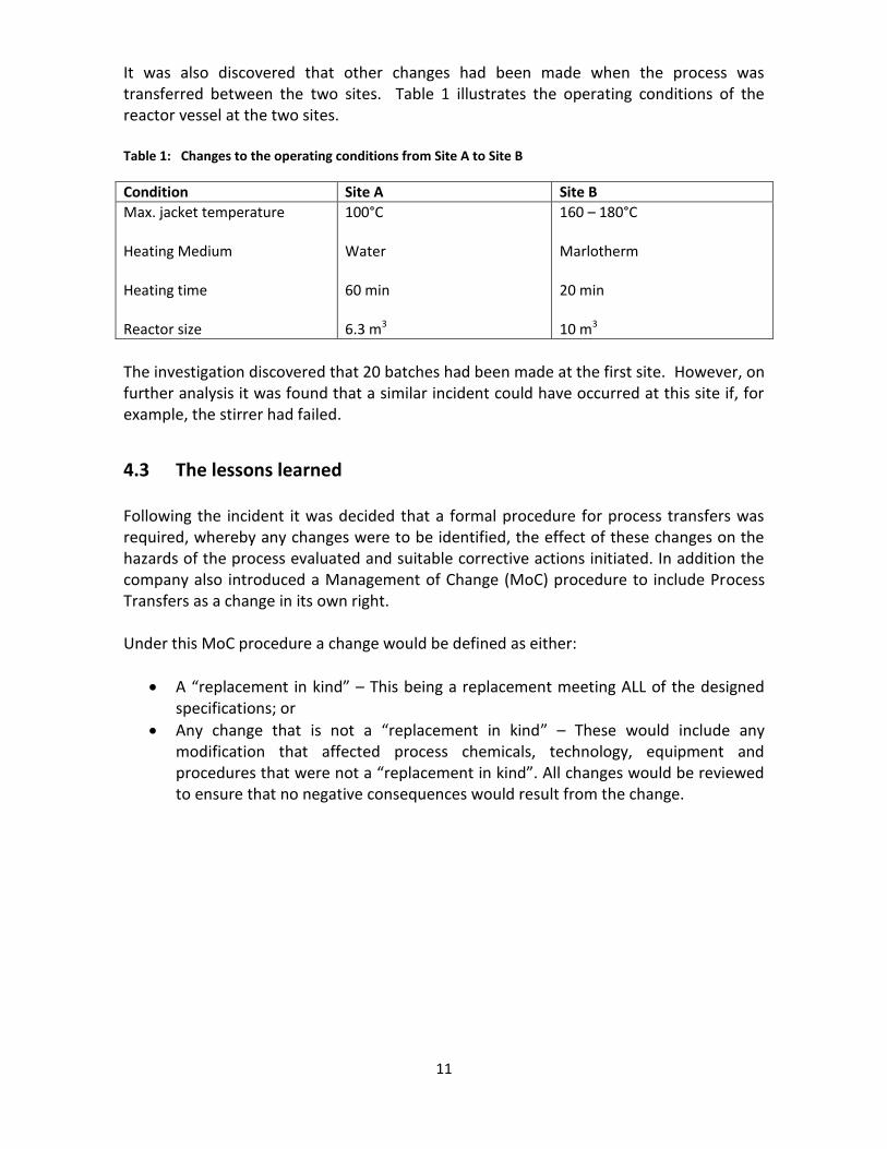
It was also discovered that other changes had been made when the process was transferred between the two sites. Table 1 illustrates the operating conditions of the reactor vessel at the two sites. Table 1: Changes to the operating conditions from Site A to Site B
Condition Site A Site B
Max. jacket temperature Heating Medium Heating time Reactor size
100°C Water 60 min 6.3 m3
160 – 180°C Marlotherm 20 min 10 m3
The investigation discovered that 20 batches had been made at the first site. However, on further analysis it was found that a similar incident could have occurred at this site if, for example, the stirrer had failed.
4.3 The lessons learned
Following the incident it was decided that a formal procedure for process transfers was required, whereby any changes were to be identified, the effect of these changes on the hazards of the process evaluated and suitable corrective actions initiated. In addition the company also introduced a Management of Change (MoC) procedure to include Process Transfers as a change in its own right. Under this MoC procedure a change would be defined as either:
A “replacement in kind” – This being a replacement meeting ALL of the designed specifications; or
Any change that is not a “replacement in kind” – These would include any modification that affected process chemicals, technology, equipment and procedures that were not a “replacement in kind”. All changes would be reviewed to ensure that no negative consequences would result from the change.

12
Examples of change could be:
Additions or deletions to a process flow sheet
Modification of process interlocks or the control rationale
Setting of new process critical limits
Using different materials of construction
Application of other safety devices
Processing of raw materials of a different quality This formal procedure was felt to provide the following advantages:
It would provide a clearly defined path for the process transfer
It would enable information to be distributed to all of the people concerned in the project
It would help prevent ill-considered changes based on “knee jerk” reactions
It would preserve the safety and control concept of the process
It would provide documentation of the change The only possible disadvantage was that, if not correctly introduced and explained, the personnel involved in the procedure could see it as an additional administrative load.
5 Some problems
This study set out to ask a number of questions including “What are the main problems, or gaps, in your way of managing process safety risks?” Part of each presentation was devoted to the problems faced by companies when they undertook the transfer of processes. These presentations gave rise to the following potential and actual issues raised by the transfer process:
If basic data on the process was missing there could be the chance that the consequences of any changes made to process parameters during the transfer would not be easily apparent. Further, significant changes to equipment may be overlooked – particularly if the process data was not accessible.
The problem of missing data was found to be most noticeable with older processes, particularly with processes introduced before the establishment of safety management systems.
Even when safety data from “older” processes was available, it was noted that it would often have been measured, or evaluated, using older methods which might not meet today’s standards.
When safety data was found to be lacking or missing, the time allotted for process transfer was often felt to be too short to produce, or prepare, the required new data. Allotting sufficient time for the safety review was also a common problem, particularly in the early stages of process transfer.
13
From the presentations a common and recurring “problem” encountered was the absence of a clear definition for safety relevant changes.
It was noted that hazard identification can take place at a very late stage in the transfer process. Safety aspects need to be considered early on in process development. This could be done through a formal safety review and the communication of safety concepts to all those involved in the development, design and transfer of batch processes.
The difficulty in keeping safety documentation up to date during the lifetime of a process was also noted. One company conducted a project to review all existing plants in order to provide documentation on the changes made, including the reason(s) for the changes. The results were then used to completely update the safety concept of the plants.
The accumulation of “small” process modifications or “creeping change”. These may result in large overall changes to the process without any formal risk assessment having been conducted.
The safety philosophy of joint venture partners may differ and differences in procedures and guidelines could arise. These differences could result in incomplete information transfer when batch recipes are transferred between joint venture partners.
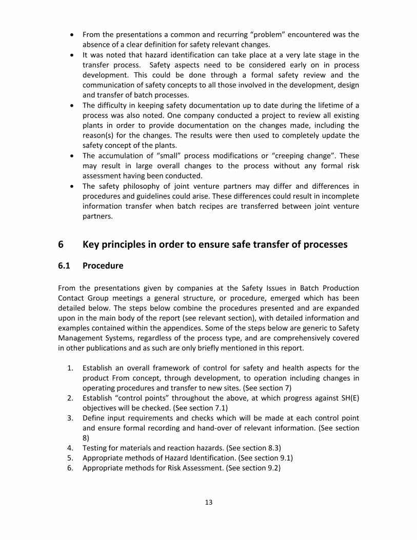
6 Key principles in order to ensure safe transfer of processes
6.1 Procedure
From the presentations given by companies at the Safety Issues in Batch Production Contact Group meetings a general structure, or procedure, emerged which has been detailed below. The steps below combine the procedures presented and are expanded upon in the main body of the report (see relevant section), with detailed information and examples contained within the appendices. Some of the steps below are generic to Safety Management Systems, regardless of the process type, and are comprehensively covered in other publications and as such are only briefly mentioned in this report.
1. Establish an overall framework of control for safety and health aspects for the product From concept, through development, to operation including changes in operating procedures and transfer to new sites. (See section 7)
2. Establish “control points” throughout the above, at which progress against SH(E) objectives will be checked. (See section 7.1)
3. Define input requirements and checks which will be made at each control point and ensure formal recording and hand-over of relevant information. (See section 8)
4. Testing for materials and reaction hazards. (See section 8.3) 5. Appropriate methods of Hazard Identification. (See section 9.1) 6. Appropriate methods for Risk Assessment. (See section 9.2)

14
7. Establish a “Basis of Safety” or “Safety Concept”. This would include the limits of safe operation in terms of materials, process limits, operating procedures etc. (See section 7.3)
8. Pre-start up safety review to ensure that all of the previous steps have been completed. (See section 10.1)
9. Control of Change — Process Change. (See section 10) 10. Trained and competent staff. (See section 12.1) 11. Audits to ensure all the above steps have been carried out. (See section 12.2)
6.2 Additional points
Additional points which were drawn from the presentations and discussions at the Contact Group meetings are outlined below:
Training of employees in how to conduct Process Risk Assessments, in addition to the safety technology employed in the process, is a prerequisite for a successful process transfer
Responsibilities before, during and after the transfer may rest with a number of groups or departments. For example risk analysis for transferred and/or changed processes was often found to be the responsibility of the site or plant that carried out the process, with central safety functions having a supporting role in the process. It was evident that wherever the responsibilities lay they needed to be clearly defined and understood by all involved in the process
Many different tools suitable for process risk analysis are available. From the presentations it became clear that checklist-based methods were applied more regularly than HAZOP for batch processes in multi-purpose plants. HAZOP methods were generally used more frequently for continuous processes or processes in mono-purpose plants
The equipment (e.g. reaction vessel, piping, process control system etc.) generally provides a set of fixed boundary conditions into which the new process needs to be introduced. In these cases greater reliance may need to be placed on organisational safety measures in order to meet the overall safety objectives

15
7 Overall framework of control
“At which steps are the process risks systematically (i.e. with protocol and follow-up)
analysed?”
It was established that all of the companies who presented at the Contact Group meetings had an overall framework of control. This included a formal set of steps during which process risks would be analysed. There were however variations in when, and by whom, these were carried out. The stages at which process risks were analysed ranged from the project definition stage, through piloting and project approval and on to the introductory campaign. The three stages at which it was most common for process risk analysis to be conducted were found to be between:
development and pilot;
pilot and commercial production; and
transfers from one site to another.
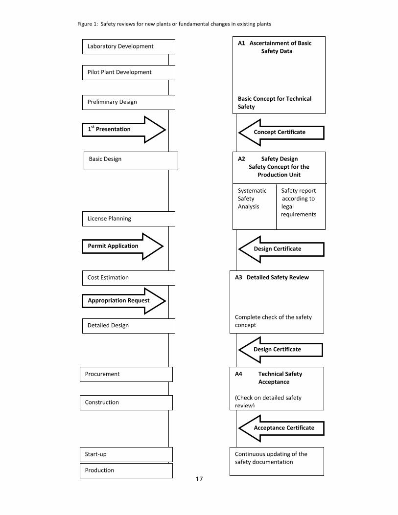
7.1 Example 2: Safety review stages
Figure 1 gives an example of the stepwise approach taken by Bayer AG to the safety review of its plants. It shows the tight integration of process risk analysis in the overall project plan. The approach was possibly the most stringent of those presented, which is in part due to the requirements of the national legislation under which Bayer AG operates. The stages were as follows: A1 – Ascertainment of Basic Safety Data
This first stage in the process requires the:
compilation and evaluation of safety data
examination of proposals for inherently safer solutions and any alternative safety concepts
safety review of the pilot plants
16
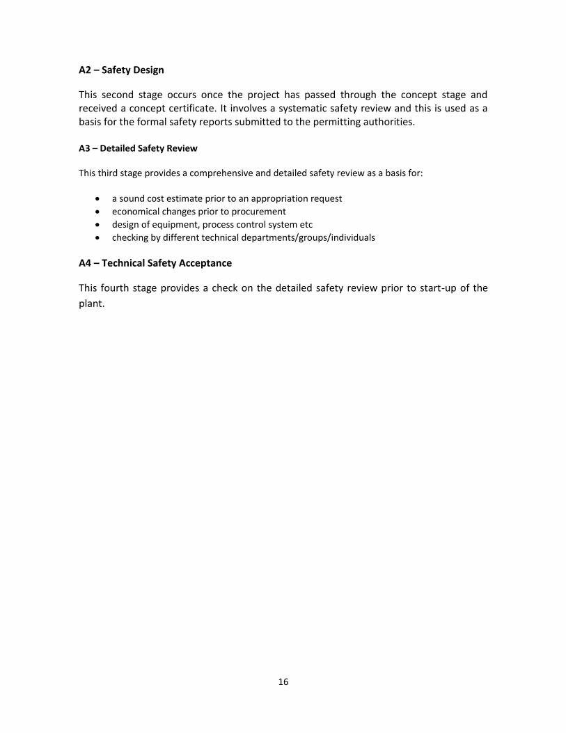
A2 – Safety Design
This second stage occurs once the project has passed through the concept stage and received a concept certificate. It involves a systematic safety review and this is used as a basis for the formal safety reports submitted to the permitting authorities. A3 – Detailed Safety Review This third stage provides a comprehensive and detailed safety review as a basis for:
a sound cost estimate prior to an appropriation request
economical changes prior to procurement
design of equipment, process control system etc
checking by different technical departments/groups/individuals
A4 – Technical Safety Acceptance
This fourth stage provides a check on the detailed safety review prior to start-up of the
plant.
17
Laboratory Development
Pilot Plant Development
Preliminary Design
A1 Ascertainment of Basic Safety Data Basic Concept for Technical Safety
1st
Presentation Concept Certificate
Basic Design
License Planning
Cost Estimation
Detailed Design
Procurement
Construction
Start-up
Production
A2 Safety Design Safety Concept for the
Production Unit Systematic Safety report Safety according to Analysis legal requirements
Permit Application Design Certificate
A3 Detailed Safety Review Complete check of the safety concept
Appropriation Request
Figure 1: Safety reviews for new plants or fundamental changes in existing plants
Design Certificate
A4 Technical Safety Acceptance (Check on detailed safety review)
Acceptance Certificate
Continuous updating of the safety documentation
18
7.2 Timeframe for process transfer
“What is the time requirement for a transfer if all process risks are analysed with due care?”
It became clear from the presentations that the time frame for performing such a process transfer was dependant on the process, the extent of safety implications and the priority given to the project, rather than the company involved. The range of times for such process transfers varied from two to six months, while the time required for the analysis of the safety implications of an individual batch process ranged from two days to four weeks. The time required depended greatly on the type of process under analysis, the type of change and the amount and quality of the preparation undertaken. It became evident that process transfer was governed, or driven, increasingly by business units rather than technical departments. The high dynamism in the chemical industry has led to a considerable acceleration in the rate at which process transfer can be accomplished. It should be noted however that in at least one case it was felt that, with proper planning, safety reviews of the process transfer were not the time determining step of the transfer procedure. The Contact Group felt that it was an important task for safety specialists to raise the awareness amongst business managers of the need for process risk assessment during the transfer procedure.
7.3 “Basis of Safety” or “Safety Concept”
This has been defined by one company such that “a safety concept is the entirety of all technical and organisational measures to control identified hazards” This company believes that such a concept has to be applied, without any restriction, to all processes, plants or operating conditions e.g.: Processes such as:
conversion
processing
handling
storage

19
Plants types including:
production plants
pilot plants
laboratories For auxiliary plant and equipment:
utilities
power plants
waste treatment plants For operating conditions such as :
start-up
normal operation
shut-down
cleaning Provided they are equally effective both technical (hardware) and organisational measures may be used to assure safety. This concept should then be applied to all aspects of:
Health
Environment
Safety
Economics In addition no distinction was made between:
new and existing plants
whether national regulations apply or not
major or minor hazards
aspects of SHE or economics The concept calls for the reduction of hazards and risks so far as is reasonably practicable in both the processes and plants (See Appendix 13 – EPSC Inherent Safer Process Plant: Good Practice)1. This has been accomplished through the application of uniform procedures and a set of criteria throughout the company. This was found to promote the integration of all the available expertise within the company for a given project.
20
8 Data requirements
8.1 Information requirements
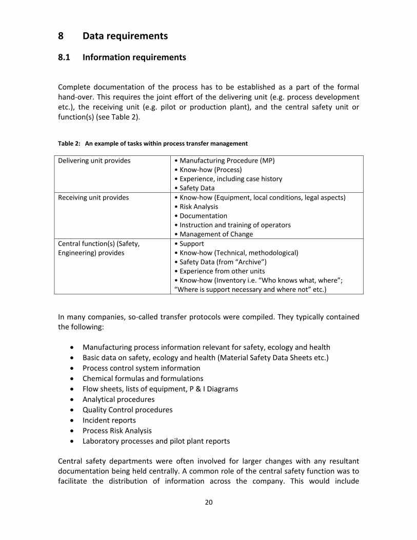
Complete documentation of the process has to be established as a part of the formal hand-over. This requires the joint effort of the delivering unit (e.g. process development etc.), the receiving unit (e.g. pilot or production plant), and the central safety unit or function(s) (see Table 2).
Table 2: An example of tasks within process transfer management
Delivering unit provides
• Manufacturing Procedure (MP) • Know-how (Process) • Experience, including case history • Safety Data
Receiving unit provides
• Know-how (Equipment, local conditions, legal aspects) • Risk Analysis • Documentation • Instruction and training of operators • Management of Change
Central function(s) (Safety, Engineering) provides
• Support • Know-how (Technical, methodological) • Safety Data (from “Archive”) • Experience from other units • Know-how (Inventory i.e. “Who knows what, where”; “Where is support necessary and where not” etc.)
In many companies, so-called transfer protocols were compiled. They typically contained the following:
Manufacturing process information relevant for safety, ecology and health
Basic data on safety, ecology and health (Material Safety Data Sheets etc.)
Process control system information
Chemical formulas and formulations
Flow sheets, lists of equipment, P & I Diagrams
Analytical procedures
Quality Control procedures
Incident reports
Process Risk Analysis
Laboratory processes and pilot plant reports Central safety departments were often involved for larger changes with any resultant documentation being held centrally. A common role of the central safety function was to facilitate the distribution of information across the company. This would include
21
information gathered during process transfer as well as that gained from incident investigations. When technology is transferred to other countries it must always be ascertained that local laws and regulations will be met. It was found that corporate policy guidelines and directives were a useful tool to fulfil the local legal requirements. They could also serve as patterns for local guidelines and directives at site level.
8.2 Safety data requirements
“What is the minimum safety data requirement? – At Pilot Stage and in Production”
The minimum safety data required varied in detail between companies, as did the data requirements at both the pilot and production stages. It was found that although comprehensive lists were available within companies the main requirements for data at the pilot plant stage included:
Basic physical properties
Toxicity
Flammability
Thermal stability
Chemical stability
Reaction kinetics
Interaction of chemicals
Interaction of chemicals with equipment
Exposure limits (Detailed toxicity data)
Ecological effects
Appendix A1 shows a translation of hand over record sheets used by BASF AG which illustrate the level of data required. When the process was moved from the pilot plant to the production stage the same data as previously listed was required, only in more detail. It was also found that the previous list was sometimes an “ideal” or “goal”, with time constraints impinging on the amount of data that could be collected. The most common cause of time constraints and overruns was found to be insufficient planning of the transfer schedule rather than the time required for technical investigations and testing. The use of generic data e.g. from analogous chemicals and reactions, literature data and model calculations was common practice amongst those who gave presentations. However, large safety factors had to be included where such data was used.
8.3 Testing for material and reaction hazards
The procedures for testing, both for material and reaction hazards, are of crucial importance in batch processing. These procedures have been comprehensively covered

22
elsewhere and as such they do not form part of this report. Below is a brief list of where further information on the topic can be found:
Barton J. and Rogers R., Chemical Reaction Hazards, IChemE, 1993.
ESCIS: Sicherheitstests für Chemikalien; ESCIS No. 1, 1998, (German)
IVSS: Determination of Combustibility and Explosion Data of Dusts, IVSS 2018 Prevention Series, 1998, (English)
Plant Safety and Thermal Stability, Störfall Kommission, SFK-GS-06, 1995
Safety and Runaway Reaction, EC JRC, 1997.
8.4 Plant data requirements
Hazard identification and risk analysis of batch processes relies not only on the data about the process itself, but also on the equipment which will be used. Whenever – and this happens frequently in batch production – a process is transferred from one reactor to another, from one plant to another, or even from one country to another, the production environment changes. As batch processing is much more reliant on manual operations and decisions than continuous processes, human and organisational aspects must be assessed alongside technical ones.
Typical technical plant parameters which are relevant for safety studies include:
Piping and instrumentation scheme
Construction materials
Pressure capabilities
Volumes and hold-ups
Flow rates
Agitators and stirrer types
Type, location and ranges of sensors (Temperature, Pressure, pH, etc.)
Inerting capabilities
Type and capacities of heating and cooling systems
Inherent and technical temperature limits for heating/cooling media
Inherent and technical limits of dosage rates
Design settings and capacities of relief systems
Interlocks
Type and capacities of auxiliary systems, such as scrubbers, condensers etc
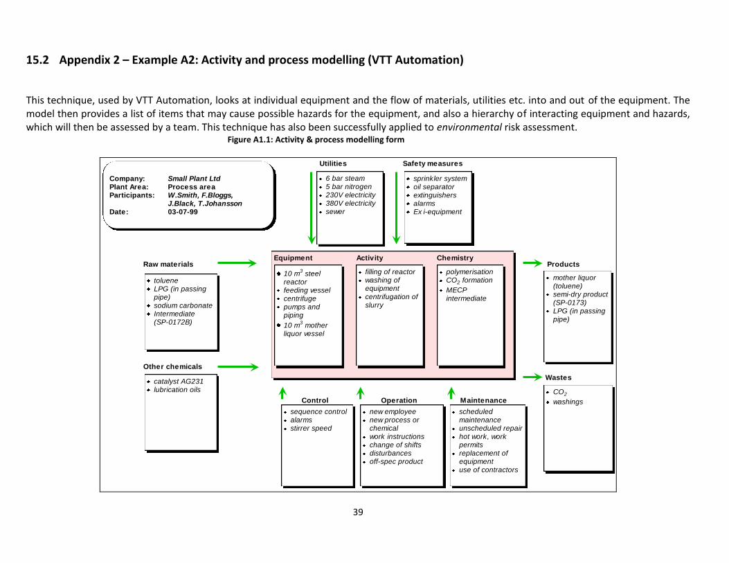
New ways to represent the plant have been developed, one of them being the Activity and Process Model (see Appendix A2, Figure A2.1). The model contains technical, human and organisational aspects that might be relevant for the safety of the process and the surrounding plant. This type of model can be drawn up for a whole plant, for a section of the plant, or for individual pieces of equipment, depending of the level of detail needed in the safety study. The tailored A & P Model can then be used as a basis for a hazard study (e.g. “What if?”).
23
9 The application of formalised tools/methods used for process risk analysis
“Are there formalised tools/methods used for process risk analysis?”
A wide variety of methods were found to be available, and in use by companies. These included methods such as checklists, HAZOPs (both “classical” and “company”-based), risk matrices and company developed procedures. Both manual and computerised methods were found to be used. Checklists were the preferred method of process risk analysis for batch processes and for use in multipurpose plants. In comparison HAZOP was favoured for continuous processes, and for use in large scale processes in dedicated mono-product plant. HAZOP was also found to be used when equipment was modified. In all cases the studies were conducted by interdisciplinary teams. In addition, whenever such tools were used they needed to fully address and consider the possible effects of human interfaces with the process under review.
9.1 Hazard Identification
9.1.1 Interaction matrix
During the transfer of processes one of the first actions to be performed was found to be a ”Preliminary Safety Analysis”. As part of this analysis an interaction matrix for all of the chemicals, materials and utility fluids used in the process would be produced. This matrix would then be used to depict any hazardous interactions – including the possible effects from incorrect charging of the reactor, any leak between the jacket and reactor etc. Appendix A3 gives an example of an interaction matrix.
9.1.2 HAZOP
HAZOP was found to be an efficient analysis tool for continuous processes, but could be difficult to apply for batch processes. The following are just three reasons proposed by the Contact Group for why HAZOP methods can prove unsuitable for use with batch processes:
P & I Diagrams normally form the basis of a HAZOP study together with process information. However, in a batch process no steady-state situations exist and the information in P & I Diagrams of the reactor and other equipment used can often be insufficient to describe and analyse complex batch systems
24
The influence of operators, and the organisation involved, on safety can be greater in batch processing relative to continuous plant, and this aspect may be difficult to systematically handle during an average HAZOP study
The activities in other parts of the plant change daily, especially if the production involves the use of multipurpose and multi-product plant
As a result the “HAZOP” method was favoured by members of the Contact Group for use:
in continuous processes
in large scale processes in dedicated mono-plants
during the modification of equipment The application of the basic HAZOP method (See joint EPSC Guide on HAZOP)2 had been found to be lengthy and time consuming by those companies who presented. In response to this various alternative “hybrids” were developed by different companies with the aim of improving the efficiency of the HAZOP method when used with batch processes. One change to the method included the application of the guidewords to the operating stages, thereby including:
charging (i.e. no charge, charge more, charge less, charge other than, etc.)
heating
stirring
etc Another approach was to select only those deviations which could lead to one of the following events:
acute intoxication
physical explosion
fire / combustion
gas explosion
dust explosion
thermal runaway
injury
9.1.3 Checklists
As reported earlier, checklists were found to be the preferred approach for Process Risk Analysis for batch and semi-batch reactions in multi-purpose plants. All of the companies who presented had developed their own set of checklists, tailor-made to their own chemistry, safety culture and technical standards. Appendix A4 shows a checklist for analysing hazards from the energy released through chemical reactions.
25
One problem identified was related to the size of the checklists, which in order to make them as complete as possible had a tendency to grow to an impractical size. One solution to this was to organise them into a hierarchical structure in which items only required consideration if certain conditions prevailed (e.g. the presence of flammable liquids). Thus reducing the size of the checklists and workload of the team involved in the study. Another concern in using checklists was that no checklist could ever be comprehensive of every situation or scenario. To ensure hazards were not overlooked many companies included an element into their checklists that allowed for “various other hazards” to be identified.
9.2 Risk Assessment
9.2.1 Deterministic view
In the deterministic approach the risk assessment classifies hazards and the respective scenarios in only two categories:
1. Hazards and scenarios that are covered by safety measures which are sufficiently reliable such that no additional measures are required
2. Hazards and scenarios that are not sufficiently covered by safety measures and therefore require an action plan
9.2.2 Probabilistic view
In the probabilistic approach the risk is expressed as a function of the probability of the occurrence of the event and the severity of the effects (consequences) of a hazardous scenario. Whether, or not, any additional measures then have to be added will depend on both of these ratings. It was found that where this approach was taken for batch processes, both probability and severity were most likely to be rated on a qualitative scale, i.e. by defining probability and severity classes. As a result so called “risk matrices” were obtained placing risks into three broad categories:
Acceptable risks
Clearly unacceptable risks
Risks which are, or are not, acceptable depending on (local) conditions Appendices A5, A6, A7 and A8 illustrate a number of risk profile methods used by companies for the probabilistic, both qualitative and quantitative, approach to risk assessment. The EPSC Contact Group Safety Decisions and Safer Design3 has compared the two approaches by studying both deterministic and probabilistic approaches to a given example and the Contact Group intends to publish its findings in the near future.
26
9.3 Assessment of process control systems (PCS)
“When is there a requirement for a systematic assessment of the PCS – By whom is it
conducted? What tools /methods are used?”
The concept for the Process Control Systems (PCS) is be developed at the initial design stages. With nearly all of the companies who presented covering the systems under the “standard” Risk Assessment conducted on the design as a whole, rather than as a specific procedure. Once a system was installed in a multi-purpose plant it was usually considered as a piece of hardware, which in turn was part of the parameters defining the suitability of the respective plant for certain processes. Some companies did specifically evaluate the process control system. This would be conducted in parallel to the safety review, with personnel ensuring the correct application of PCS according to internal company guidelines. When formal approaches were used, they were found to be largely derived from the NAMUR recommendations NE314. The lack of useful tools in this field for the use by small (in most cases very small) batch plants has also been reflected in the EPSC report on Safety Critical systems5.
9.4 Assessment of reactors and other equipment
“Is there any systematic assessment of reactors and other equipment with regard to the adequacy of technical parameters (agitation, mixing, energy in/out capacities)?”
The consensus was that the assessment of reactors and other equipment came either under existing safety review processes or was integrated with the risk analysis. Questions relevant to safety would be covered by the safety review during process transfer, while other questions concerning the adequacy of the equipment would be clarified in the design phase. Later safety reviews were used to verify and/or confirm the adequacy of any design with respect to the safety concepts, with these reviews normally conducted by a Risk Assessment team. In a number of companies the central safety group would be expected to have a record of the expertise available on any individual site. From this knowledge they would then be able to decide whether the site required external assistance with any particular assessment.
27
9.5 Risk Documentation
All of the members of the Contact Group acknowledged the importance placed upon the correct and adequate documentation of the safety reviews. The documentation should be a structured account of the discussions looking at all the possible causes, their respective consequences and then the reasoning for any measures recommended or taken. This documentation would be the basis for:
the design of equipment, process control systems and safe operating limits
inspections by technical and safety departments prior to start-up
the preparation of safety reports for permitting authorities
the management of change
operating procedures
training of employees The documentation has to be updated over the lifetime of a plant, so that the latest version of the entire safety concept is always available for any plant or site.
9.6 Human Factors
Human fallibility was felt to be well known, if not well understood, and the “human factor” in the search for hazards should be taken into account during the risk analysis.
28
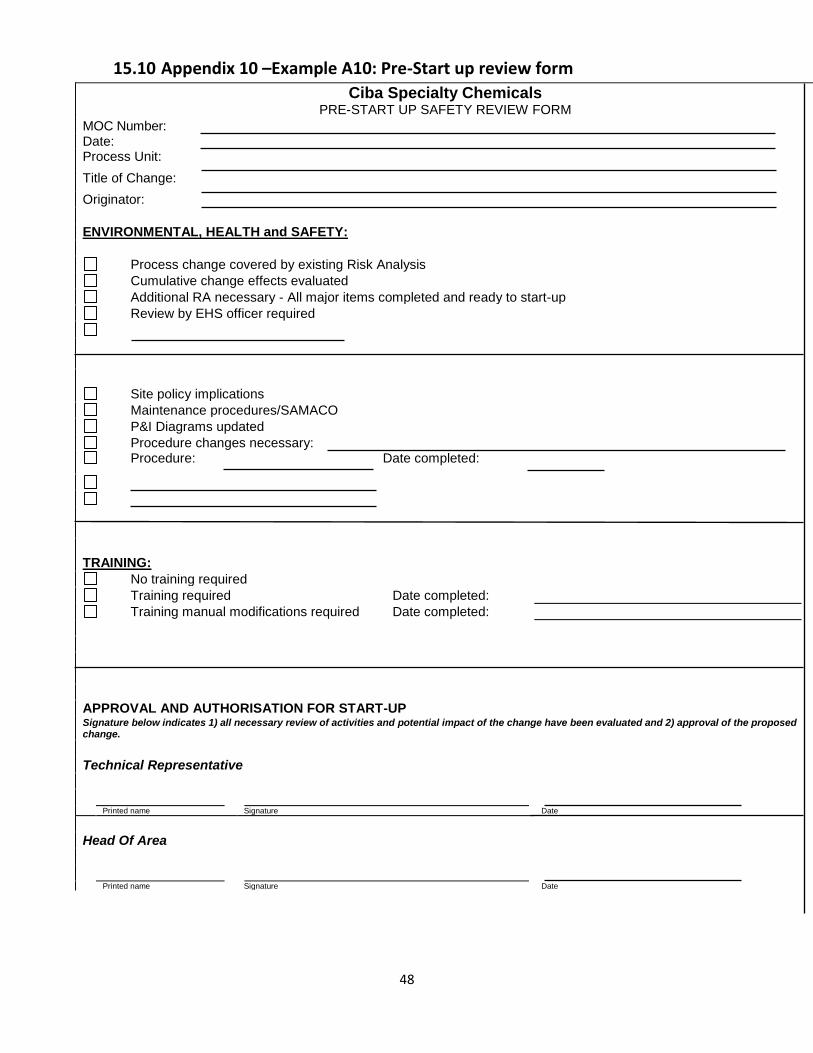
10 Control of Change “Does a Management of Change Procedure exist, considering the safety relevance of changes?” In general there were no Management of Change (MoC) Guidelines specifically for process transfer within the companies who presented. However, in all cases it was either already covered by more general safety procedures or in some instances specific procedures were in the process of being drawn up. The most common approach was that the process transfer would come under existing MoC procedures and individual production managers would use these guidelines to assess the safety impacts of any transfer. The production manager would then decide whether to involve the central process safety department (if one was available). To complete the procedure all the relevant documentation (operation manual, P&ID, etc.) would be updated, personnel informed and adequately trained. Appendix A9 and A10 show the MoC form and Pre-start up safety review form used by Ciba Specialty Chemicals. A “change” includes all intentional modifications to procedures and equipment, other than “replacement in kind”, which might have an impact upon either the environment, occupational hygiene or safety. A “replacement in kind” was defined as a change which met all of the designed specifications. An example of a change would be replacing a membrane valve with a ball valve — instead of replacing the valve with one that is in all respects identical (Appendix A11 shows further examples of replacement in kind versus changes).
10.1 Pre-Start Up Review
After the change has been carried out, and before start-up, a number of checks should be conducted. These can be aided by checklists (see Appendix A10: Pre-Start Up review form). Further, Figure 1 from Example 2: Safety review stages (section 7.1) contains a “Technical Safety Acceptance” stage which was used by Bayer AG and conducted prior to start-up as a check on the detailed safety review process.
10.2 “Major” or “minor”?
It was noted that often it was difficult to define what changes constituted a notifiable change. This could lead to situations where processes develop their own “life” on different sites. Although having such a definition would make the demarcation of safety responsibilities easier, the difficulties of producing an “ideal” definition for all changes would be difficult, if not impossible. Fixed rules in that area could also lead to unit/plant managers having a false sense of security when making decisions on “major” and “minor” changes based on formal criteria. Unit/plant managers should have the correct level of education and the necessary training to be able to provide individual decisions, using on-site experience, on a case-by-case basis.
29
11 Control of processes during their lifecycle “Who keeps control on processes during their lifecycle?”
Although all of the companies who presented had corporate policies on process safety management the control of processes was largely decentralised to the operating plants/divisions. The production management was usually given control over the documentation and this would be passed on with any process transfer. By giving control to the local (on-site) operating management a better control of small changes was felt to be possible. Moreover the local conditions e.g. education and experience of personnel, legislation, age of the equipment and instrumentation of the plant can be taken into account more precisely at a local level. Decentralised processes tended to develop in different ways when carried out in different plants. The control of such changes and in particular the criteria on when they deserve or require more detailed safety considerations was found to be difficult to manage. Appendix A12 shows the approach taken by Bayer AG to the application of such control to an existing plant/process.
12 Safety Management Systems (SMS)
The previous sections have dealt with issues specific to the management of process transfers. It must be remembered that such transfers should be incorporated within an overall Safety Management System. This report does not intend to go into detail about SMS as previous Contact Groups have worked on this topic and have produced relevant publications6.
12.1 Training
12.1.1 Operator training
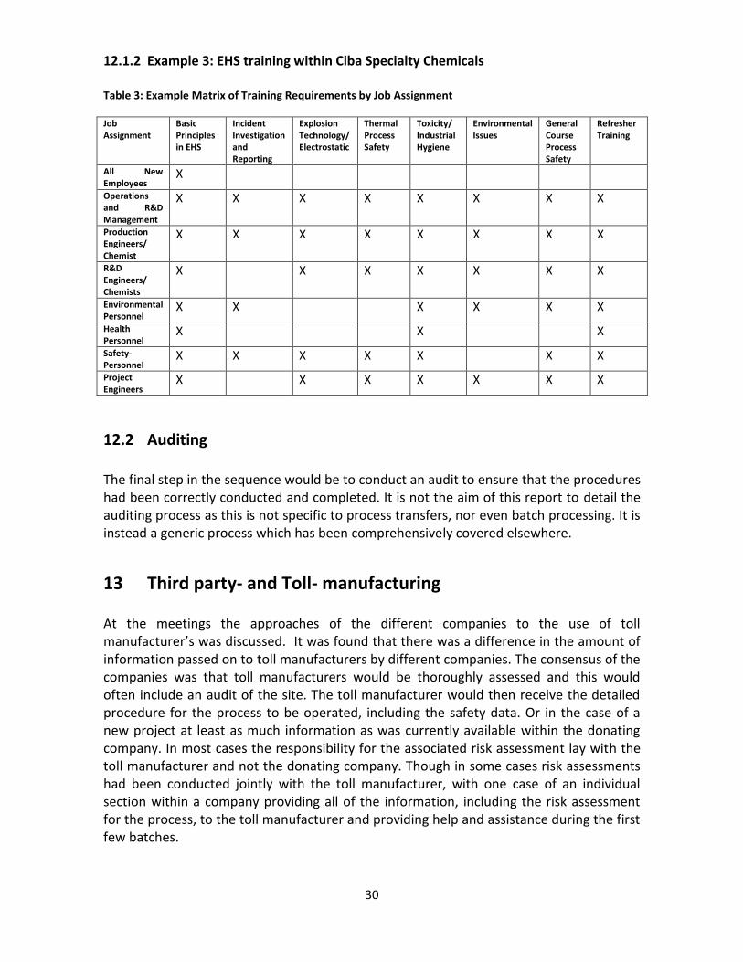
Sites/companies were found to ensure that the site’s chemists and engineers were trained in the use of relevant risk analysis techniques. For larger studies the Central Safety Departments would often become involved bringing with them their expertise in the use of these techniques. Example 3 shows how one company trained its employees (professionals) in safety, health and environment issues (See Appendix A13 for an example matrix of training requirements by job assignment).
30
12.1.2 Example 3: EHS training within Ciba Specialty Chemicals
Table 3: Example Matrix of Training Requirements by Job Assignment
Job Assignment
Basic Principles in EHS
Incident Investigation and Reporting
Explosion Technology/ Electrostatic
Thermal Process Safety
Toxicity/ Industrial Hygiene
Environmental Issues
General Course Process Safety
Refresher Training
All New Employees
X
Operations and R&D Management
X X X X X X X X
Production Engineers/ Chemist
X X X X X X X X
R&D Engineers/ Chemists
X X X X X X X
Environmental Personnel
X X X X X X
Health Personnel
X X X
Safety-Personnel
X X X X X X X
Project Engineers
X X X X X X X
12.2 Auditing
The final step in the sequence would be to conduct an audit to ensure that the procedures had been correctly conducted and completed. It is not the aim of this report to detail the auditing process as this is not specific to process transfers, nor even batch processing. It is instead a generic process which has been comprehensively covered elsewhere.
13 Third party- and Toll- manufacturing
At the meetings the approaches of the different companies to the use of toll manufacturer’s was discussed. It was found that there was a difference in the amount of information passed on to toll manufacturers by different companies. The consensus of the companies was that toll manufacturers would be thoroughly assessed and this would often include an audit of the site. The toll manufacturer would then receive the detailed procedure for the process to be operated, including the safety data. Or in the case of a new project at least as much information as was currently available within the donating company. In most cases the responsibility for the associated risk assessment lay with the toll manufacturer and not the donating company. Though in some cases risk assessments had been conducted jointly with the toll manufacturer, with one case of an individual section within a company providing all of the information, including the risk assessment for the process, to the toll manufacturer and providing help and assistance during the first few batches.
31
14 References and sources of information
1. Inherently Safer Process Plant: Good Practice, EPSC Publication (See Appendix 13).
2. HAZOP: Guide to best practice, EPSC/CIA/IChemE Guide, January 2000, ISBN 0
85295 427 1.
3. Safety Decisions and Safer Designs – quantitative risk and deterministic methods,
EPSC Contact Group. This group will publish the conclusions from its study of
different methods of making design decisions, as applied to a sample problem.
4. NAMUR recommendation NE31, Safety of Process Plants Using Measurement and
Control Equipment, 1995.
5. Overview of safety critical systems for process plant and their management, EPSC
Report No 9, August 1995.
6. Safety Management Systems, EPSC, 1995, ISBN 0-85295-356-9.
32
14.1 Sources of information
14.1.1 Referring to batch processing in general
• Guidelines for process safety in batch operations, September 1999, CCPS, ISBN 0- 8169-0780-3 14.1.2 Referring to safety data:
• Barton, J. and Rogers, R., Chemical Reaction Hazards, Second edition, IChemE, 1997 • ESCIS: Sicherheitstests für Chemikalien, ESCIS No. 1, 1998, (German) • IVSS: Determination of Combustibility and Explosion Data of Dusts, IVSS Prevention Series 2018, 1998, (English) • Plant Safety and Thermal Stability, Störfall Kommission, SFK-GS-06, 1995 • Safety and Runaway Reactions, EC JRC, 1997 14.1.3 Referring to Zurich Hazard Analysis: • Clariant: Process Risk Analysis Guide, 1998 • Zurich Insurance: Zurich Hazard Analysis, 1998 • Zurich Insurance: ZHANT: A software package for Zurich Hazard Analysis, Version 2.0; 1999
14.1.4 Referring to process risk analysis in general: • Clariant: Leitfaden Gefahrenanalyse, 1999, (German) • ESCIS: Einführung in die Risikoanalyse, ESCIS No. 4, 1996, (German) • ESCIS: Thermal Process Safety; ESCIS No. 8, 1989, (English) • Grewer, Th., Thermal hazards of chemical reactions, Elsevier, 1994 • Pitblado, R. and Turney R., Risk Analysis in the Process Industries, IChemE, 1996
14.1.5 Referring to HAZOP: • HAZOP: Guide to best practice, EPSC/CIA/IChemE Guide, January 2000, ISBN 0 85295 427 1 • IVSS: The PAAG-Procedure (HAZOP), IVSS Prevention Series, 1990, (English) 14.1.6 Referring to process control:
• NAMUR: Normangemeinschaft für Mess- und Regelungstechnik in der Chemischen Industrie: Anlagensicherung mit Mitteln der Prozessleittechnik, NE 31, 1992, (German)
33
14.1.7 Referring to management of change • Modifications: The Management of Change, Training Package No 025, Institution of Chemical Engineers, 1996 14.1.8 Referring to toll manufacturing: • Clariant: Guideline on Third Party Manufacturing, 1996.
14.2 General sources of information
AIChE – American Institute of Chemical Engineers 3 Park Avenue New York NY 10016-5991 Tel: +1-800-242-4363 http://www.aiche.org
CCPS – Center for Chemical Process Safety 3 Park Avenue New York NY 10016-5991 Tel: + 1 212 591-7319, Fax: +1 212 591-8895 Email: [email protected]; http://www.aiche.org/ccps CHEMSAFE – a numerical database containing fire and explosion protection information and is produced by Dechema. (More information is available at (http://www.dechema.de/englisch/iud/pages/chemsafe.html) DECHEMA e.V. Theodor-Heuss-Allee 25 D-60486 Frankfurt Germany Tel: +49 (0)69 75640, Fax: +49 (0) 69 7564 201 http://www.dechema.de DIERS – Design Institute for Emergency Relief Systems http://www.aiche.org/diers EC Joint Research Centre http://www.jrc.org/jrc/index.asp European Process Safety Centre http://www.epsc.org
34
IChemE – Institution of Chemical Engineers Davis Building Railway Terrace Rugby Warwickshire CV21 3HQ, UK Tel: +44 (0)1788 578214, fax: + 44 (0)1788 560833 http://www.icheme.org HARSNET – EU-funded thematic network aiming to produce technical guidance for SMEs. http://harsnet.iqs.url.es NAMUR – An international association of users of process control technology in the chemical, pharmaceutical and allied industries in the German speaking regions. http://www.namur.de Safety-net – EU-funded electronic network on industrial safety, fire and explosion protection. This network is operated principally through the World Wide Web using electronic newsletters, an on-line database containing summaries of research results and monthly electronic seminars. (More information is available at http://www.safetynet.de SFK – Störfall-Kommission (Major Hazards Commission) Gesellschaft für Anlagen-und Reaktorsicherheit (GRS) mbH Geschäftsstelle Störfall-Kommission und Technischer Ausschub für Anlagensicherheit Schwertnergasse 1 50667 Köln Tel: + 49 (0) 221 2068 715, Fax: + 49 (0) 221 2068 890 TAA – Technischer Ausschuss für Anlagensicherheit (Technical Committee for Plant Safety) Gesellschaft für Anlagen-und Reaktorsicherheit (GRS) mbH Geschäftsstelle Störfall-Kommission und Technischer Ausschub für Anlagensicherheit Schwertnergasse 1 50667 Köln Tel: + 49 (0) 221 2068 244, Fax: + 49 (0) 221 2068 309

35
UIC – Union des Industries Chimiques http://www.uic.fr Zurich Hazard Analysis Zurich Insurance Company Risk Engineering Mythenquai 10 8002 Zurich Switzerland Tel: +41 (0)1 205 3951, Fax: +41 (0)1 205 2600 http://www.zurich.com/Sites/CHK/Zfsfs.nsf/htmlmedia/re_-_main.html

36
15 Appendices

37
15.1 Appendix 1 – Example A1: Translation of BASF Hand over record sheet Figure A1.1: Hand over sheet (part I)
Handover record sheet - data section Date
in accordance with Guideline for Environmental Protection and Safety at Work No. 3-1 Code
Procedure for the manufacture of Employee's name
Telephone no
Materials used Description of material (see 1)
1. Core data for technical safety
Gaseous and liquid materials
Description
of material (see 1)
Melting
point
Boiling point
at 1013 mbar
Flame point
at ºC / not
applicable
Flash point
ºC / not
applicable
Explosion
point vol.
% / not
applicable
Can material
deflagrate
Danger of
explosion
Known to
react
dangerously
with …..
Yes No Yes No
Solid materials
Description
of material (see 1)
Burning
value BV
……….. at
…... ºC
Auto ignites
above ºC on
spillage
of………ml
Promotes
burning
Can explode
as dust
Minimum
ignition
energy
Can material
deflagrate
Danger of
explosion
Known to
react
dangerously
with …..
Yes No Yes No mJ Yes No Yes No
Thermal stability of initial materials, end products and mixtures produced through reactions,
and trials to test storability in warm temperatures in so far as these are required by DTA
Description
of material (see 1)
Thermally
stable up to
….ºC (see 4)
DTA Exotherm reaction
after ºC
Released heat kJ/kg Storage in warm conditions trial
exothermic reaction after ºC
Other tests, observations
1) Description of material: E=active ingredient Z=by product, F=finished product, numbered in sequence E1, Z1, F1
2) As defined in the Explosive Materials Law
3) Nominal size refers to dust that has been swirled up
4) If, in the case of a possible incident, a safety zone of approx. 100 ºC from the point at which the
material would become unstable, can be adhered to,or if the thermic potential is considered slight(e.g. H < 200 J/g), then what is referred to in the enclosure can be dispensed with

38
Figure A1.2: Hand over record sheet (part II)
2. Health & Safety Data
Classification according to the DangerousSubstances Regulations and the MAK List
Description of
material (see 1)T+, T or Xn C or Xi H or S Causes cancer Changes DNA structure Endangers reproductive ability
Work safety limits and toxicological data
Description of material (see 1) Air limit LD 5 mg/ kg (oral) LD 50 mg/kg (dermal) LC 50 mg / 1/4 h (inhaled)
(See 2) Value g/m3
Material data which is relevant to the environment Duty of disclosure under the
Description of material (see 1)
Elimination (see 3) WGKDangerous Substances
Regulations
Proscribed
Chemicals
Regulations
Incident
Regulations
Use of
Chemicals
Law
in Zahn-Wellens Test
1) Description of material: E= active ingredient Z = by product, F = finished product, numbered in sequence E1, Z1, F1
2)MAK, TRK
3) The attainment of good elimination in the Zahn-Wellens Test does not automatically mean the tested substance may be introduced into the purification unit.
Any such step must first be discussed with the DUU/W and contact must also be made with this body regarding the drawing up of anHBV Protection concept,
which is obligatory.
Place a cross in the box if applicable
39
15.2 Appendix 2 – Example A2: Activity and process modelling (VTT Automation)
This technique, used by VTT Automation, looks at individual equipment and the flow of materials, utilities etc. into and out of the equipment. The model then provides a list of items that may cause possible hazards for the equipment, and also a hierarchy of interacting equipment and hazards, which will then be assessed by a team. This technique has also been successfully applied to environmental risk assessment. Figure A1.1: Activity & process modelling form
Equipment Activity ChemistryRaw materials Products
Wastes
Control Operation Maintenance
Utilities Safety measures
Other chemicals
10 m3 steel
reactorfeeding vesselcentrifugepumps andpiping
10 m3 motherliquor vessel
filling of reactorwashing ofequipmentcentrifugation ofslurry
polymerisationCO2 formation
MECPintermediate
tolueneLPG (in passingpipe)sodium carbonateIntermediate(SP-0172B)
6 bar steam5 bar nitrogen230V electricity380V electricitysewer
sprinkler systemoil separatorextinguishersalarmsEx i-equipment
mother liquor(toluene)semi-dry product(SP-0173)LPG (in passingpipe)
CO2
washings
sequence controlalarmsstirrer speed
scheduledmaintenanceunscheduled repairhot work, workpermitsreplacement ofequipmentuse of contractors
new employeenew process orchemicalwork instructionschange of shiftsdisturbancesoff-spec product
Company: Small Plant LtdPlant Area: Process areaParticipants: W.Smith, F.Bloggs,
J.Black, T.JohanssonDate: 03-07-99
catalyst AG231lubrication oils

40
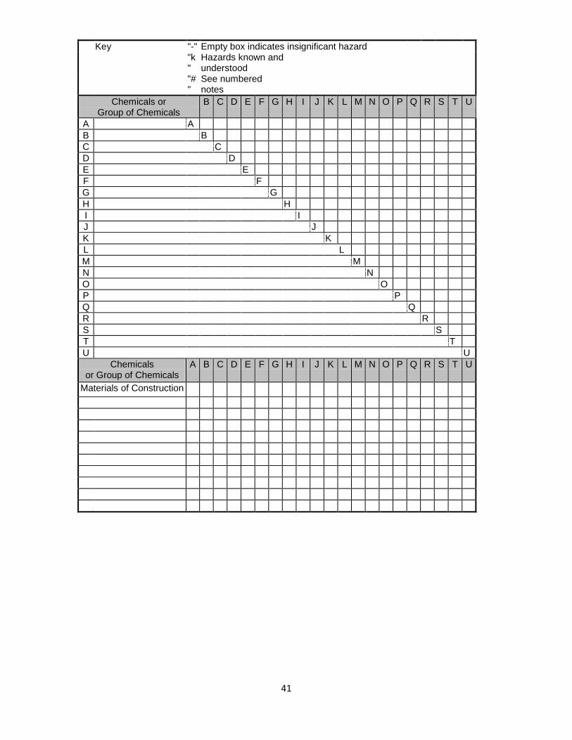
15.3 Appendix 3 – Example A3: Chemical interaction proforma
The purpose of the proforma is to identify any combinations of materials used in, or near, the process which are incompatible or have a significant hazard potential. For new projects, the compiled information is used by the design team in developing the design. For existing processes, the complied information can be used to ensure that hazards (both known and possibly unknown [new] – due to changes in process chemistry, operating conditions, materials, equipment or operating procedures) are reviewed. The adequacy of the existing process operating-, control-, protective- or emergency- systems and procedures can then be checked. The proforma is usually used before the concept stage meeting and reviewed at the meeting. Procedure
1. List all the materials on the proforma under “Chemical or Group of Chemicals”. Be as descriptive as possible, i.e. use the recognised chemical name or names and include any trade names and abbreviations or product code name/numbers. Materials of construction should be listed in the lower section of the proforma: these include materials in direct contact with process fluids but consideration should also be given to other tools and equipment or building/construction materials which may come into contact with the process material.
2. Use the matrix to consider possible hazardous interactions of each material with each of the other materials in the top section of the proforma and with materials of construction in the lower section.
3. The matrix should stimulate creative thinking and questions, and will probably involve obtaining data from experts in fire/explosion-, health- and environmental- hazards. Based on the information, the proforma should be completed with one of the 3 responses:
"-" The material has no significant hazard in this aspect. "K" The hazards are known and well understood and available to the concept study and design teams and the process management. "#" See numbered notes attached. (These notes would be for use within the company and are note reproduced here.)
41
Key "-" Empty box indicates insignificant hazard "k
" Hazards known and understood
"#"
See numbered notes
Chemicals or Group of Chemicals
B C D E F G H I J K L M N O P Q R S T U
A A
B B
C C
D D
E E
F F
G G
H H
I I
J J
K K
L L
M M
N N
O O
P P
Q Q
R R
S S
T T
U U
Chemicals or Group of Chemicals
A B C D E F G H I J K L M N O P Q R S T U
Materials of Construction
42
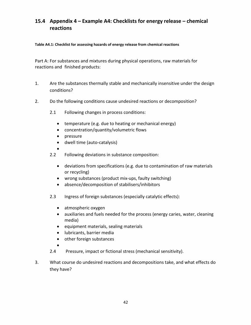
15.4 Appendix 4 – Example A4: Checklists for energy release – chemical reactions
Table A4.1: Checklist for assessing hazards of energy release from chemical reactions
Part A: For substances and mixtures during physical operations, raw materials for reactions and finished products:
1. Are the substances thermally stable and mechanically insensitive under the design
conditions?
2. Do the following conditions cause undesired reactions or decomposition?
2.1 Following changes in process conditions:
temperature (e.g. due to heating or mechanical energy)
concentration/quantity/volumetric flows
pressure
dwell time (auto-catalysis)
2.2 Following deviations in substance composition:
deviations from specifications (e.g. due to contamination of raw materials or recycling)
wrong substances (product mix-ups, faulty switching)
absence/decomposition of stabilisers/inhibitors
2.3 Ingress of foreign substances (especially catalytic effects):
atmospheric oxygen
auxiliaries and fuels needed for the process (energy caries, water, cleaning media)
equipment materials, sealing materials
lubricants, barrier media
other foreign substances
2.4 Pressure, impact or fictional stress (mechanical sensitivity).
3. What course do undesired reactions and decompositions take, and what effects do
they have?
43
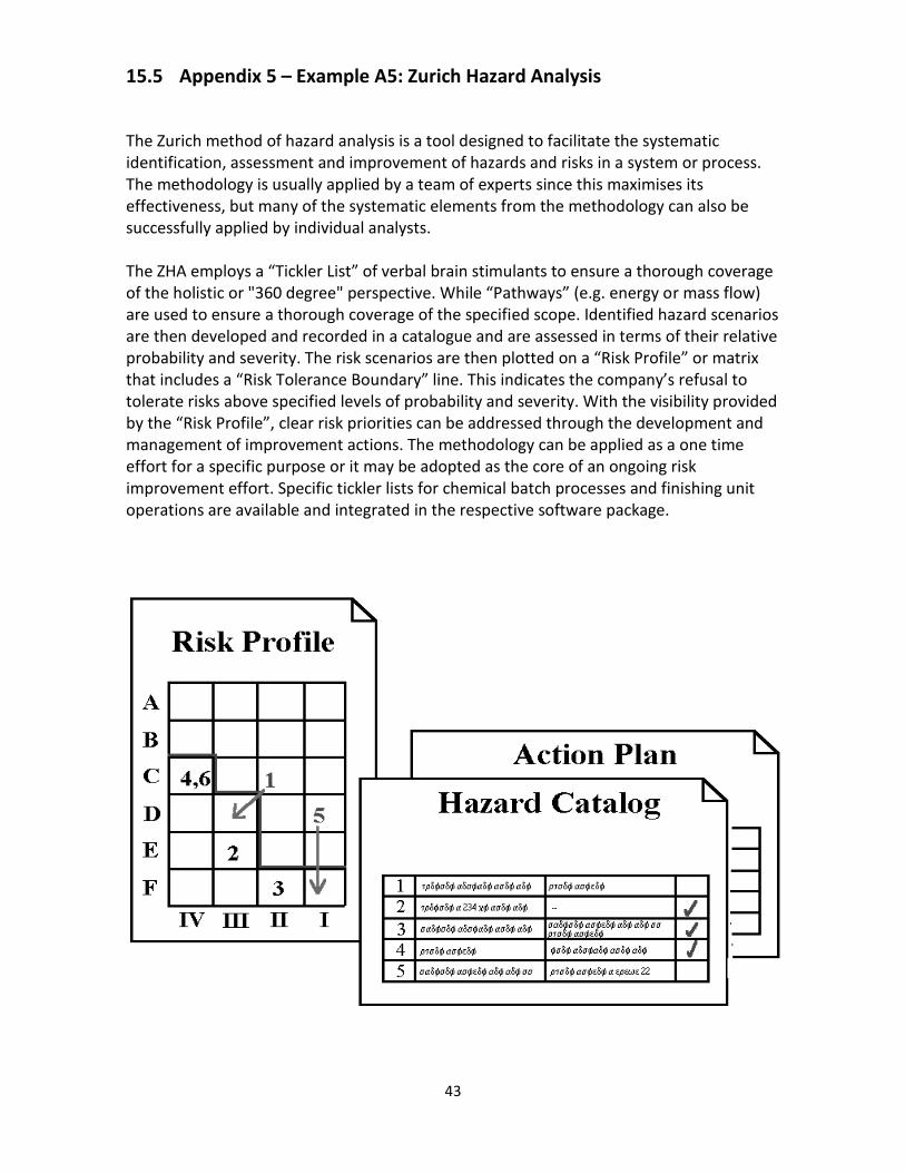
15.5 Appendix 5 – Example A5: Zurich Hazard Analysis
The Zurich method of hazard analysis is a tool designed to facilitate the systematic identification, assessment and improvement of hazards and risks in a system or process. The methodology is usually applied by a team of experts since this maximises its effectiveness, but many of the systematic elements from the methodology can also be successfully applied by individual analysts. The ZHA employs a “Tickler List” of verbal brain stimulants to ensure a thorough coverage of the holistic or "360 degree" perspective. While “Pathways” (e.g. energy or mass flow) are used to ensure a thorough coverage of the specified scope. Identified hazard scenarios are then developed and recorded in a catalogue and are assessed in terms of their relative probability and severity. The risk scenarios are then plotted on a “Risk Profile” or matrix that includes a “Risk Tolerance Boundary” line. This indicates the company’s refusal to tolerate risks above specified levels of probability and severity. With the visibility provided by the “Risk Profile”, clear risk priorities can be addressed through the development and management of improvement actions. The methodology can be applied as a one time effort for a specific purpose or it may be adopted as the core of an ongoing risk improvement effort. Specific tickler lists for chemical batch processes and finishing unit operations are available and integrated in the respective software package.
44
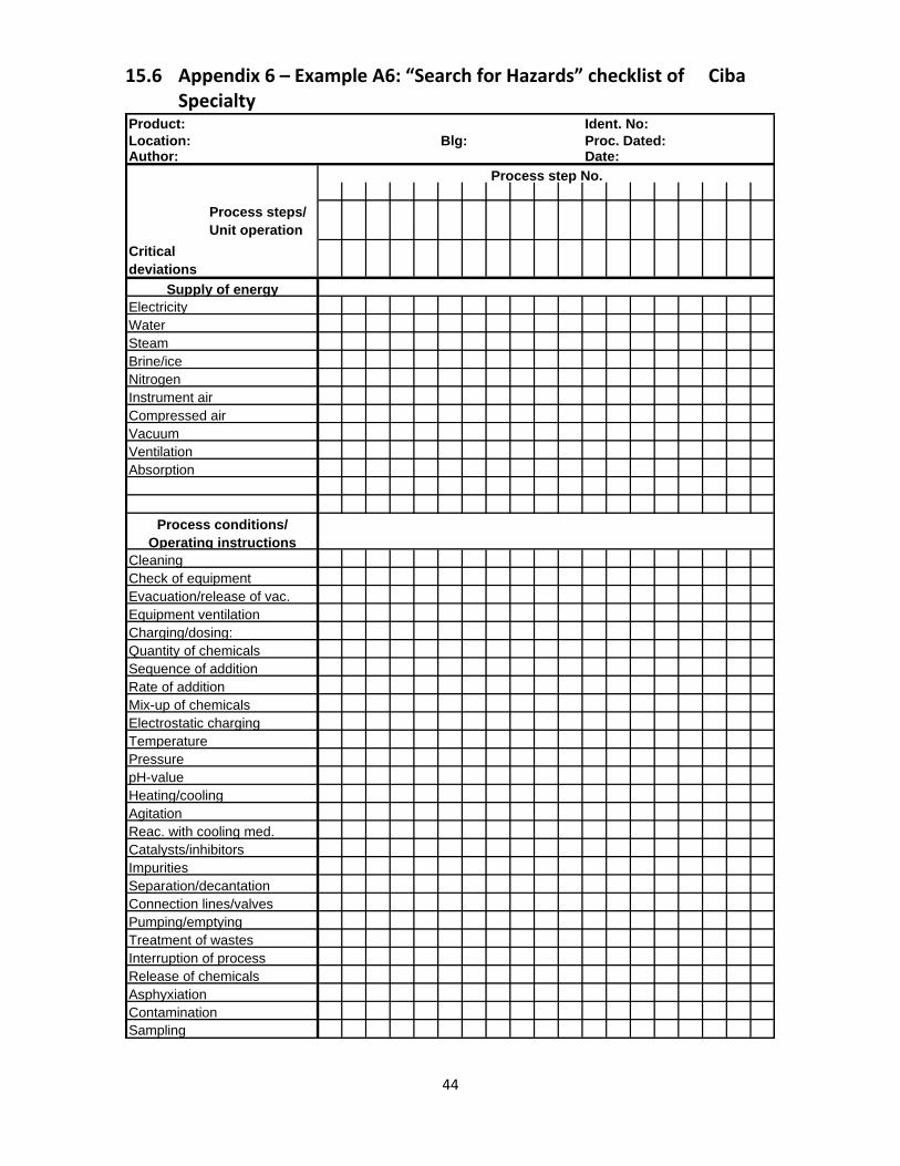
15.6 Appendix 6 – Example A6: “Search for Hazards” checklist of Ciba Specialty Product: Ident. No:
Location: Blg: Proc. Dated:Author: Date:
Process step No.
Process steps/
Unit operation
Critical
deviations
Supply of energy
Electricity
Water
Steam
Brine/ice
Nitrogen
Instrument air
Compressed air
Vacuum
Ventilation
Absorption
Process conditions/
Operating instructions
Cleaning
Check of equipment
Evacuation/release of vac.
Equipment ventilation
Charging/dosing:
Quantity of chemicals
Sequence of addition
Rate of addition
Mix-up of chemicals
Electrostatic charging
Temperature
Pressure
pH-value
Heating/cooling
Agitation
Reac. with cooling med.
Catalysts/inhibitors
Impurities
Separation/decantation
Connection lines/valves
Pumping/emptying
Treatment of wastes
Interruption of process
Release of chemicals
Asphyxiation
Contamination
Sampling
45
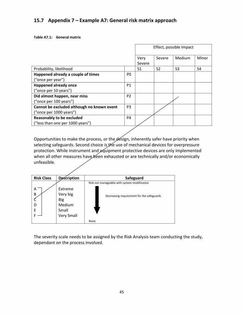
15.7 Appendix 7 – Example A7: General risk matrix approach
Table A7.1: General matrix
Effect, possible Impact
Very Severe
Severe
Medium Minor
Probability, likelihood S1 S2 S3 S4
Happened already a couple of times (“once per year”)
P0
Happened already once (“once per 10 years”)
P1
Did almost happen, near miss (“once per 100 years”)
P2
Cannot be excluded although no known event (“once per 1000 years”)
P3
Reasonably to be excluded (“less than one per 1000 years”)
P4
Opportunities to make the process, or the design, inherently safer have priority when selecting safeguards. Second choice is the use of mechanical devices for overpressure protection. While instrument and equipment protective devices are only implemented when all other measures have been exhausted or are technically and/or economically unfeasible.
Risk Class Description Safeguard
A B C D E F
Extreme Very big Big Medium Small Very Small
Risk not manageable with system modification
Decreasing requirement for the safeguards
None
The severity scale needs to be assigned by the Risk Analysis team conducting the study, dependant on the process involved.
46
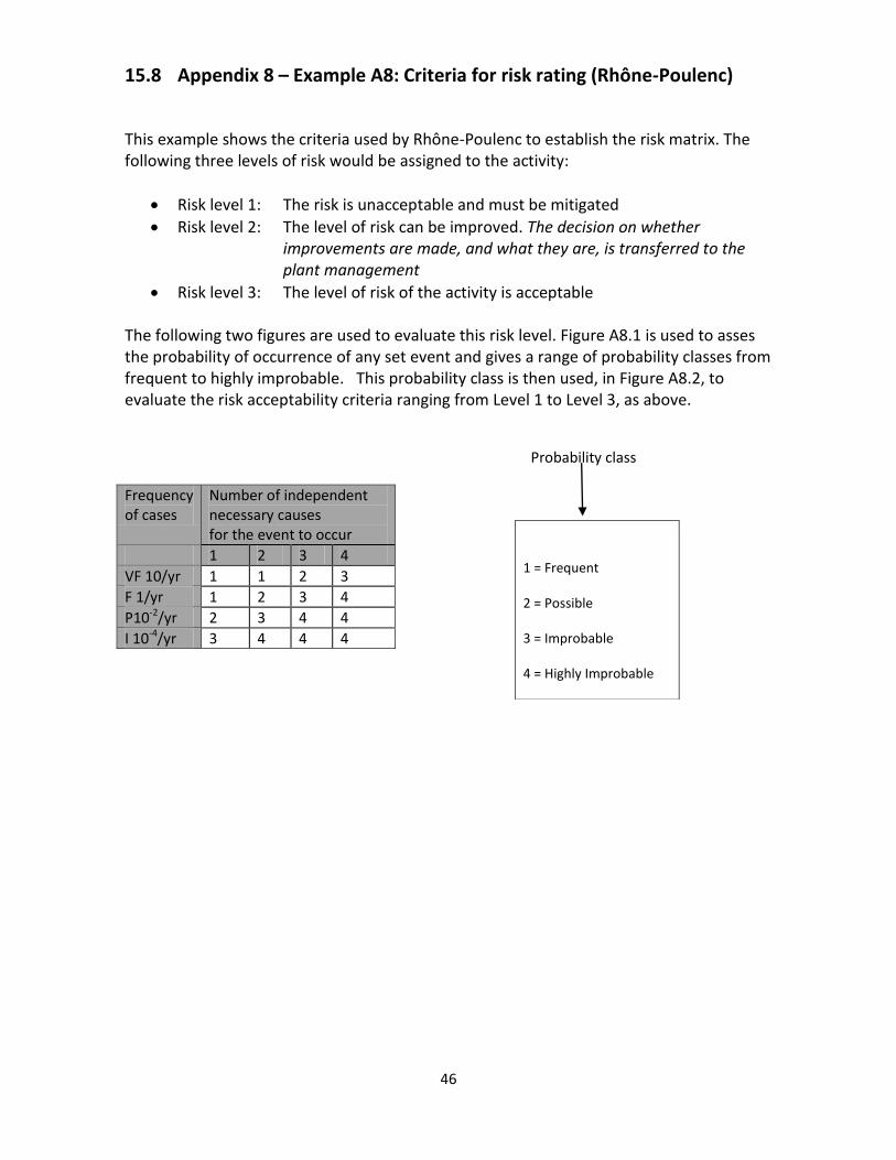
15.8 Appendix 8 – Example A8: Criteria for risk rating (Rhône-Poulenc)
This example shows the criteria used by Rhône-Poulenc to establish the risk matrix. The following three levels of risk would be assigned to the activity:
Risk level 1: The risk is unacceptable and must be mitigated
Risk level 2: The level of risk can be improved. The decision on whether improvements are made, and what they are, is transferred to the plant management
Risk level 3: The level of risk of the activity is acceptable The following two figures are used to evaluate this risk level. Figure A8.1 is used to asses the probability of occurrence of any set event and gives a range of probability classes from frequent to highly improbable. This probability class is then used, in Figure A8.2, to evaluate the risk acceptability criteria ranging from Level 1 to Level 3, as above.
Probability class
Frequency of cases
Number of independent necessary causes for the event to occur
1 2 3 4
VF 10/yr 1 1 2 3
F 1/yr 1 2 3 4
P10-2/yr 2 3 4 4
I 10-4/yr 3 4 4 4
1 = Frequent
2 = Possible
3 = Improbable
4 = Highly Improbable

47
15.9 Appendix 9 – Example A9: Process change request form
Ciba Specialty Chemicals PROCESS CHANGE REQUEST FORM
MOC Number:
Date:
Process Unit:
Title of Change:
Originator:
Type of Change:
Temporary change Permanent change
Start Date: Duration of Change:
Description and Purpose of Process Change:
Technical Basis of Proposed Change:
Impact on Environment, Health and Safety
APPROVAL Signature below indicates 1) all necessary review of activities and potential impact of the change have been evaluated and 2) approval of the proposed change.
Technical Representative
Printed name Signature Date
Head of Area
Printed name Signature Date
48
15.10 Appendix 10 –Example A10: Pre-Start up review form
Ciba Specialty Chemicals PRE-START UP SAFETY REVIEW FORM
MOC Number:
Date:
Process Unit:
Title of Change:
Originator:
ENVIRONMENTAL, HEALTH and SAFETY:
Process change covered by existing Risk Analysis
Cumulative change effects evaluated
Additional RA necessary - All major items completed and ready to start-up
Review by EHS officer required
Site policy implications
Maintenance procedures/SAMACO
P&I Diagrams updated
Procedure changes necessary: Procedure: Date completed:
TRAINING:
No training required
Training required Date completed:
Training manual modifications required Date completed:
APPROVAL AND AUTHORISATION FOR START-UP Signature below indicates 1) all necessary review of activities and potential impact of the change have been evaluated and 2) approval of the proposed change.
Technical Representative
Printed name Signature Date
Head Of Area
Printed name Signature Date
49
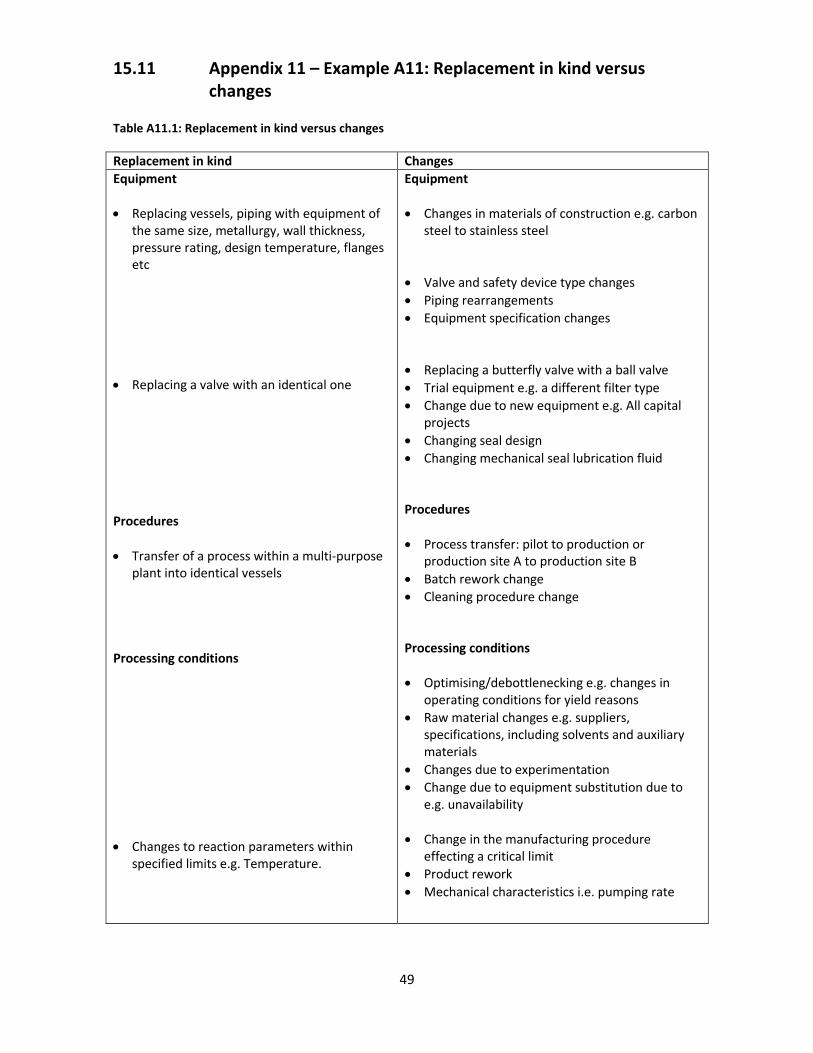
15.11 Appendix 11 – Example A11: Replacement in kind versus changes Table A11.1: Replacement in kind versus changes
Replacement in kind Changes
Equipment
Replacing vessels, piping with equipment of the same size, metallurgy, wall thickness, pressure rating, design temperature, flanges etc
Replacing a valve with an identical one Procedures
Transfer of a process within a multi-purpose plant into identical vessels
Processing conditions
Changes to reaction parameters within specified limits e.g. Temperature.
Equipment
Changes in materials of construction e.g. carbon steel to stainless steel
Valve and safety device type changes
Piping rearrangements
Equipment specification changes
Replacing a butterfly valve with a ball valve
Trial equipment e.g. a different filter type
Change due to new equipment e.g. All capital projects
Changing seal design
Changing mechanical seal lubrication fluid Procedures
Process transfer: pilot to production or production site A to production site B
Batch rework change
Cleaning procedure change Processing conditions
Optimising/debottlenecking e.g. changes in operating conditions for yield reasons
Raw material changes e.g. suppliers, specifications, including solvents and auxiliary materials
Changes due to experimentation
Change due to equipment substitution due to e.g. unavailability
Change in the manufacturing procedure effecting a critical limit
Product rework
Mechanical characteristics i.e. pumping rate

50
15.12 Appendix 12 – Example A12: Application to an existing plant (Bayer AG)
Example 2: Safety review stages, section 7.1, illustrates Bayer AG’s approach to safety reviews for new and fundamental changes to existing plants. However, it is equally important to ensure that hazards are controlled on existing plants even when no fundamental changes are being made to the process or the facility. For existing plants, as opposed to new, the first three review stages (A1, A2 and A3 from Example 2) can be combined, because all of the information necessary to perform a systematic, comprehensive and detailed safety review should already exist or can be easily compiled. The result of this combining of stages is shown in Figure A12.1 below.
Comparison of actual installation versus design
Functional check
A4 Technical Safety
Acceptance
A1 + A2 + A3
Verification of the completeness of the basic safety data and documentation
Systematic safety review of the safety concept for the process/production unit
Compilation of additional measures (with agreed-upon interim solutions)
Production
Planning for the Action Items
resulting from the reviews
Request for Investment Funds
Safety Certificate (Team) Implementation of the
Measures
Acceptance Certificate
Continuous updating of the
safety documentation
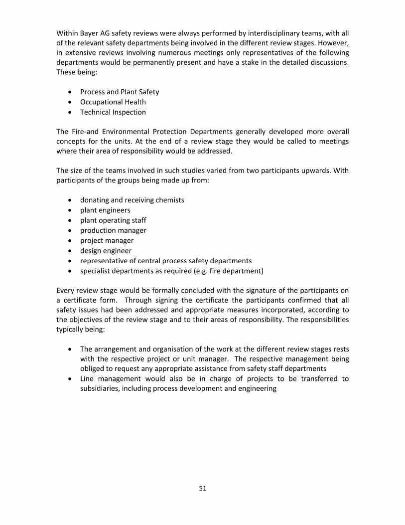
51
Within Bayer AG safety reviews were always performed by interdisciplinary teams, with all of the relevant safety departments being involved in the different review stages. However, in extensive reviews involving numerous meetings only representatives of the following departments would be permanently present and have a stake in the detailed discussions. These being:
Process and Plant Safety
Occupational Health
Technical Inspection The Fire-and Environmental Protection Departments generally developed more overall concepts for the units. At the end of a review stage they would be called to meetings where their area of responsibility would be addressed. The size of the teams involved in such studies varied from two participants upwards. With participants of the groups being made up from:
donating and receiving chemists
plant engineers
plant operating staff
production manager
project manager
design engineer
representative of central process safety departments
specialist departments as required (e.g. fire department) Every review stage would be formally concluded with the signature of the participants on a certificate form. Through signing the certificate the participants confirmed that all safety issues had been addressed and appropriate measures incorporated, according to the objectives of the review stage and to their areas of responsibility. The responsibilities typically being:
The arrangement and organisation of the work at the different review stages rests with the respective project or unit manager. The respective management being obliged to request any appropriate assistance from safety staff departments
Line management would also be in charge of projects to be transferred to subsidiaries, including process development and engineering
52
15.13 Appendix 13 – Inherently safer processes and plants
Inherently safer processes and plants
It is good practice to apply Inherent Safety principles when developing a new process or plant – or when considering changes to existing ones. At the heart of the inherent safety concept is the desire to step back from the prevailing tendency to design complex safety systems to control the hazards of proposed processes, and fundamentally review the process in terms of:
can we use a safer route to manufacture the product which involves less hazardous raw materials and intermediates?
can the quantity of hazardous materials involved be reduced, and can the physical conditions in which they are processed be moderated?
an the equipment used to perform the various unit operations of the process be selected to optimise their safety and reliability?
Applying Inherent Safety principles can reduce the hazards to people’s safety, the hazards to their health, and the hazards to the environment. In addition a positive business case can often be made for designing an inherently safer plant. Inventory levels may be minimised, reducing the capital held up in feedstock, intermediate and product storage. A simpler plant may be more reliable and need less maintenance. Waste minimisation can reduce both production costs and environmental impact. Application of Inherent Safety within an organisation can be most effective if:
it is supported by a ‘champion’ at a senior level within the company
staff from a broad range of disciplines, including chemists, process engineers, control engineers, mechanical engineers and designers are provided with suitable training and made aware of the principles of Inherent Safety
it is applied from the very earliest stages of process and project development;
reviews are carried out at set points during a project to identify how well the principles of Inherent Safety have been applied and
teams and individuals that are successful in the application of Inherent Safety are recognised and rewarded by the company
The greatest value may be obtained by using an integrated approach to improve the safety, occupational health and environmental impact of a process. The common Inherent Safety guidewords, as outlined below, can be applied throughout the design process to help those involved consider alternatives.
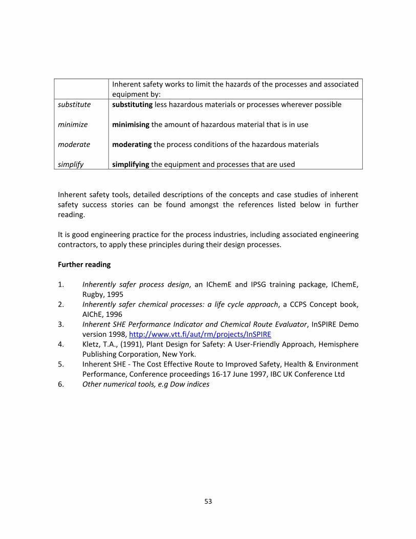
53
Inherent safety works to limit the hazards of the processes and associated equipment by:
substitute minimize moderate simplify
substituting less hazardous materials or processes wherever possible minimising the amount of hazardous material that is in use moderating the process conditions of the hazardous materials simplifying the equipment and processes that are used
Inherent safety tools, detailed descriptions of the concepts and case studies of inherent safety success stories can be found amongst the references listed below in further reading. It is good engineering practice for the process industries, including associated engineering contractors, to apply these principles during their design processes. Further reading 1. Inherently safer process design, an IChemE and IPSG training package, IChemE, Rugby, 1995 2. Inherently safer chemical processes: a life cycle approach, a CCPS Concept book, AIChE, 1996 3. Inherent SHE Performance Indicator and Chemical Route Evaluator, InSPIRE Demo version 1998, http://www.vtt.fi/aut/rm/projects/InSPIRE 4. Kletz, T.A., (1991), Plant Design for Safety: A User-Friendly Approach, Hemisphere Publishing Corporation, New York. 5. Inherent SHE - The Cost Effective Route to Improved Safety, Health & Environment Performance, Conference proceedings 16-17 June 1997, IBC UK Conference Ltd 6. Other numerical tools, e.g Dow indices


![International Journal of Pure and Applied Mathematics ...batch/semi batch [6], fixed bed, fluidized bed, spouted bed, microwave [7] and screw kiln. Batch or semi -batch reactors have](https://img.pdfslide.net/doc/110x75/6042d371c8d4a7373d406703/international-journal-of-pure-and-applied-mathematics-batchsemi-batch-6.jpg)