Embed Size (px)
Citation preview
J
J-15www.sti.com/info
Safety Monitoring Relays
G9SX-GS
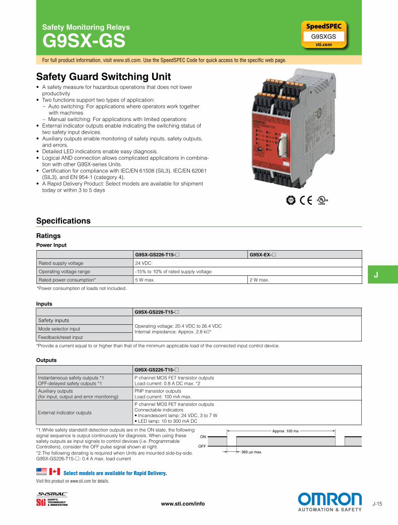
Safety Guard Switching Unit• A safety measure for hazardous operations that does not lower
productivity• Two functions support two types of application:
– Auto switching: For applications where operators work together with machines
– Manual switching: For applications with limited operations• External indicator outputs enable indicating the switching status of
two safety input devices.• Auxiliary outputs enable monitoring of safety inputs, safety outputs,
and errors.• Detailed LED indications enable easy diagnosis.• Logical AND connection allows complicated applications in combina-
tion with other G9SX-series Units.• Certification for compliance with IEC/EN 61508 (SIL3), IEC/EN 62061
(SIL3), and EN 954-1 (category 4).• A Rapid Delivery Product: Select models are available for shipment
today or within 3 to 5 days
For full product information, visit www.sti.com. Use the SpeedSPEC Code for quick access to the specific web page.
Select models are available for Rapid Delivery.Visit this product on www.sti.com for details.
Specifications
G9SX-GS226-T15-□ G9SX-EX-□Rated supply voltage 24 VDC
Operating voltage range -15% to 10% of rated supply voltage
Rated power consumption* 5 W max. 2 W max.
*Power consumption of loads not included.
G9SX-GS226-T15-□Safety inputs
Operating voltage: 20.4 VDC to 26.4 VDC Internal impedance: Approx. 2.8 kΩ*
Mode selector input
Feedback/reset input
*Provide a current equal to or higher than that of the minimum applicable load of the connected input control device.
G9SX-GS226-T15-□Instantaneous safety outputs *1 OFF-delayed safety outputs *1
P channel MOS FET transistor outputs Load current: 0.8 A DC max. *2
Auxiliary outputs (for input, output and error monitoring)
PNP transistor outputs Load current: 100 mA max.
External indicator outputs
P channel MOS FET transistor outputs Connectable indicators • Incandescent lamp: 24 VDC, 3 to 7 W • LED lamp: 10 to 300 mA DC
Inputs
Outputs
RatingsPower Input
ON
OFF
360 µs max.
Approx. 100 ms
*2. The following derating is required when Units are mounted side-by-side.G9SX-GS226-T15-□: 0.4 A max. load current
*1. While safety standstill detection outputs are in the ON state, the following signal sequence is output continuously for diagnosis. When using these safety outputs as input signals to control devices (i.e. Programmable Controllers), consider the OFF pulse signal shown at right.
G9SXGS
J
J-16 www.sti.com/info
Specifications (continued)
G9SX-GS226-T15-□ G9SX-EX-□Number of Units connected per logical AND output 4 Units max. ---
Total number of Units connected by logical AND *1 20 Units max. ---
Number of Units connected in series by logical AND 5 Units max. ---
Max. number of Expansion Units connected *2 --- 5 Units max.
Maximum cable length for logical AND input 100 m max. ---
Note: See Logical AND Connection Combinations below for details.*1. The number of G9SX-EX401-□ Expansion Units or G9SX-EX041-T-□ Expansion Units (OFF-delayed Model) not included.*2. G9SX-EX401-□ Expansion Units and G9SX-EX041-T-□ Expansion Units (OFF-delayed Model) can be mixed.
Logical AND Connection
G9SX-GS Safety Monitoring Relays
Wiring
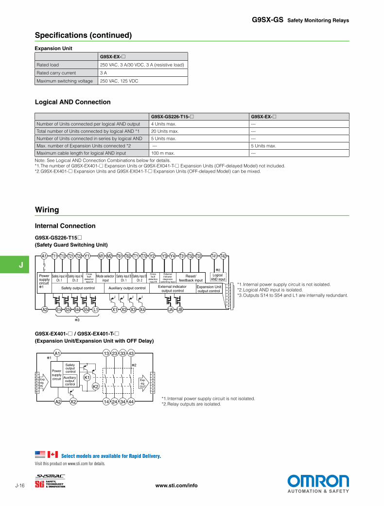
Internal Connection
G9SX-GS226-T15□(Safety Guard Switching Unit)
*1. Internal power supply circuit is not isolated.*2. Logical AND input is isolated.*3. Outputs S14 to S54 and L1 are internally redundant.
G9SX-EX401-□ / G9SX-EX401-T-□(Expansion Unit/Expansion Unit with OFF Delay)
*1. Internal power supply circuit is not isolated.*2. Relay outputs are isolated.
*2
S14A2 S24 S44 S54 L1 X1 X2 X3 X4 UA UB
Safety output control Auxiliary output control Expansion Unitoutput control
T11A1 T12 T21 T22 Y1 M1 M2 T61 T62 T71 T72 Y2 Y3 Y4 T31 T32 T33 T41 T42
Logical AND input
Reset/feedback input
External indicator diagnosis
switching input
Safety input BCh. 2
Safety input BCh. 1
Mode selector input
Safety input ACh. 2
Safety input ACh. 1
External indicator output control
Powersupplycircuit*1
*3
Cross fault
detection input B
Cross fault
detection input A
A2 X2
Power supply circuit Auxiliary
output control
Safety output control
A1
K1
13 23 33 43
14 24 34 44
K2
Exp. sig.IN
Exp.sig.
OUT
*1
*2
Select models are available for Rapid Delivery.Visit this product on www.sti.com for details.
G9SX-EX-□Rated load 250 VAC, 3 A/30 VDC, 3 A (resistive load)
Rated carry current 3 A
Maximum switching voltage 250 VAC, 125 VDC
Expansion Unit
J
J-17www.sti.com/info
G9SX-GS Safety Monitoring Relays
System Configuration Examples
3
4
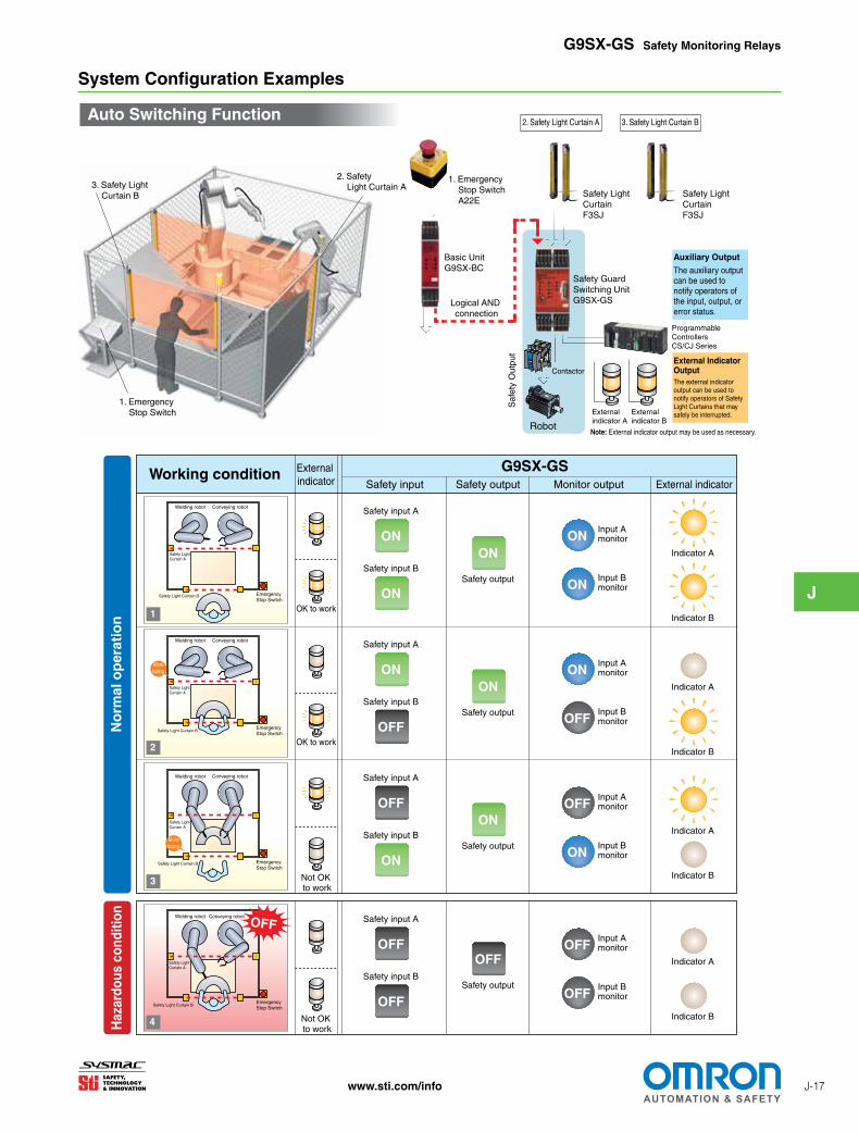
Auto Switching Function
Basic UnitG9SX-BC
Logical AND connection
1. Emergency Stop Switch A22E
1. Emergency Stop Switch
2. Safety Light Curtain A3. Safety Light
Curtain B Safety Light CurtainF3SJ
Safety Light CurtainF3SJ
Safety Guard Switching UnitG9SX-GS
Saf
ety
Out
put
Auxiliary Output
The auxiliary output can be used to notify operators of the input, output, or error status.
External Indicator OutputThe external indicator output can be used to notify operators of Safety Light Curtains that may safely be interrupted.
Note: External indicator output may be used as necessary.Robot
Contactor
External indicator A
External indicator B
Programmable ControllersCS/CJ Series
Welding robot
Emergency Stop Switch
Conveying robot
Welding robot
Emergency Stop Switch
Haz
ardo
us c
ondi
tion
Not OK to work
Not OK to work
OFF
Safety Light Curtain A
Safety Light Curtain B
Safety Light Curtain A
Safety Light Curtain B
Moni-toring
Conveying robot
Working condition External indicator
OK to work
Welding robot
Emergency Stop Switch
Conveying robot
Welding robot
Emergency Stop Switch
Conveying robot
1
No
rmal
op
erat
ion
OK to work
Safety Light Curtain A
Safety Light Curtain B
Safety Light Curtain A
Safety Light Curtain B
Moni-toring
G9SX-GSSafety input Safety output Monitor output External indicator
Safety input A
Safety input BSafety output
ON
ONON
Input A monitor
Input B monitor
ON
ON
Input A monitor
Input B monitor
ON
OFF
Input A monitor
Input B monitor
OFF
ON
Input A monitor
Input B monitor
OFF
OFF
Safety input A
Safety input BSafety output
OFF
ONON
Safety input A
Safety input BSafety output
ON
ONOFF
Safety input A
Safety input BSafety output
OFF
OFFOFF
Indicator A
Indicator B
Indicator A
Indicator B
Indicator A
Indicator B
Indicator A
Indicator B
2
2. Safety Light Curtain A 3. Safety Light Curtain B
J
J-18 www.sti.com/info
G9SX-GS Safety Monitoring Relays
System Configuration Examples (continued)
Emergency Stop Switch
Mode selector
Emergency Stop Switch
Mode selector
Emergency Stop Switch
Mode selector
Emergency Stop Switch
Mode selector
4
2
3
1
Normal operating mode
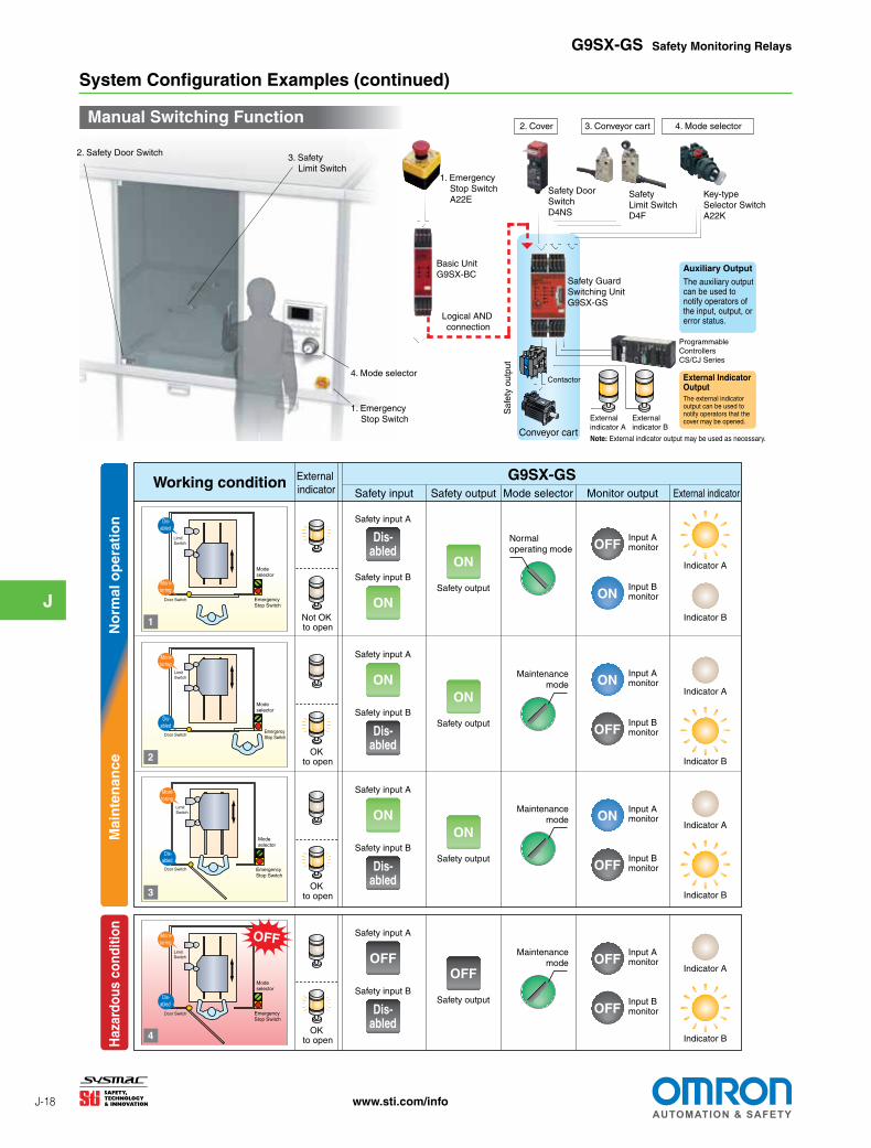
Working condition G9SX-GSSafety input
External indicator
Safety input A
Safety input BSafety output
Safety output Mode selector
ON
ON
Input A monitor
Input B monitor
OFF
OFF
Safety input A
Safety input BSafety output
ONON
Safety input A
Safety input B
ON
Safety input A
Safety input BSafety output
OFFOFF
No
rmal
op
erat
ion
Mai
nte
nan
ceH
azar
dous
con
ditio
n
Maintenance mode
Maintenance mode
Not OK to open
OK to open
OK to open
OK to open
OFF
Limit Switch
Door Switch
Limit Switch
Door Switch
Limit Switch
Door Switch
Limit Switch
Door Switch
Dis-abled
Moni-toring
Moni-toring
Moni-toring
Moni-toring
Dis-abled
Dis-abled
Dis-abled Dis-
abled
Dis-abled
Dis-abled
Dis-abled
Monitor output External indicator
Input A monitor
Input B monitor
OFF
ON
Input A monitor
Input B monitor
ON
OFF
Input A monitor
Input B monitor
ON
OFFSafety output
ON
Maintenance mode
Indicator A
Indicator B
Indicator B
Indicator A
Indicator B
Indicator A
Indicator B
Indicator A
Manual Switching Function
Basic UnitG9SX-BC
Logical AND connection
Saf
ety
outp
ut
1. Emergency Stop Switch A22E
Safety Limit SwitchD4F
Key-type Selector Switch A22K
Safety Door SwitchD4NS
Safety Guard Switching UnitG9SX-GS
2. Cover 3. Conveyor cart
Conveyor cart
4. Mode selector
Auxiliary Output
The auxiliary output can be used to notify operators of the input, output, or error status.
External Indicator OutputThe external indicator output can be used to notify operators that the cover may be opened.
Contactor
Note: External indicator output may be used as necessary.
1. Emergency Stop Switch
3. Safety Limit Switch
2. Safety Door Switch
4. Mode selector
External indicator A
External indicator B
Programmable ControllersCS/CJ Series
J
J-19www.sti.com/info
G9SX-GS Safety Monitoring Relays
Functions
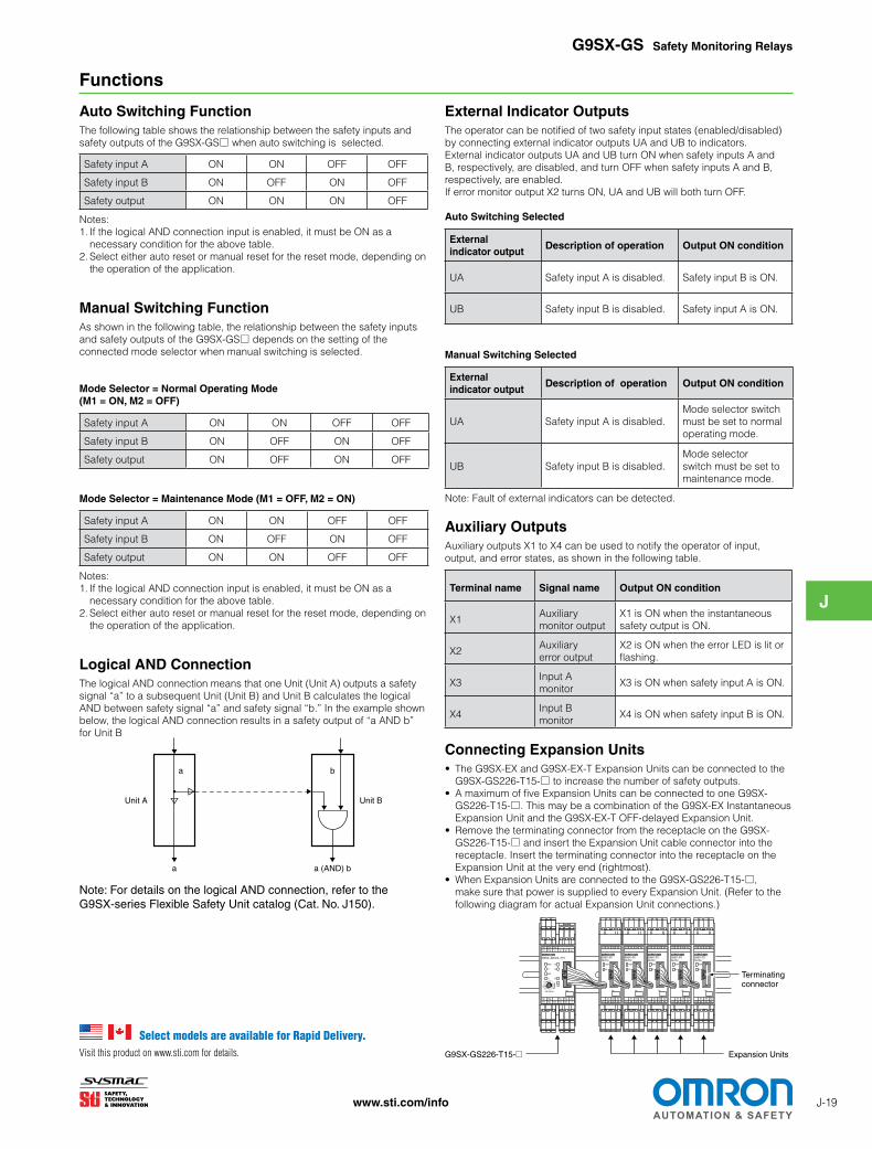
Auto Switching FunctionThe following table shows the relationship between the safety inputs and safety outputs of the G9SX-GS□ when auto switching is selected.
Safety input A ON ON OFF OFF
Safety input B ON OFF ON OFF
Safety output ON ON ON OFF
Notes:1. If the logical AND connection input is enabled, it must be ON as a
necessary condition for the above table.2. Select either auto reset or manual reset for the reset mode, depending on
the operation of the application.
Manual Switching FunctionAs shown in the following table, the relationship between the safety inputs and safety outputs of the G9SX-GS□ depends on the setting of the connected mode selector when manual switching is selected.
Mode Selector = Normal Operating Mode (M1 = ON, M2 = OFF)
Safety input A ON ON OFF OFF
Safety input B ON OFF ON OFF
Safety output ON OFF ON OFF
Mode Selector = Maintenance Mode (M1 = OFF, M2 = ON)
Safety input A ON ON OFF OFF
Safety input B ON OFF ON OFF
Safety output ON ON OFF OFF
Notes:1. If the logical AND connection input is enabled, it must be ON as a
necessary condition for the above table.2. Select either auto reset or manual reset for the reset mode, depending on
the operation of the application.
Logical AND ConnectionThe logical AND connection means that one Unit (Unit A) outputs a safety signal “a” to a subsequent Unit (Unit B) and Unit B calculates the logical AND between safety signal “a” and safety signal “b.” In the example shown below, the logical AND connection results in a safety output of “a AND b” for Unit B
Note: For details on the logical AND connection, refer to the G9SX-series Flexible Safety Unit catalog (Cat. No. J150).
a
a b
a (AND) b
Unit BUnit A
External Indicator OutputsThe operator can be notified of two safety input states (enabled/disabled) by connecting external indicator outputs UA and UB to indicators. External indicator outputs UA and UB turn ON when safety inputs A and B, respectively, are disabled, and turn OFF when safety inputs A and B, respectively, are enabled.If error monitor output X2 turns ON, UA and UB will both turn OFF.
Auto Switching Selected
External indicator output
Description of operation Output ON condition
UA Safety input A is disabled. Safety input B is ON.
UB Safety input B is disabled. Safety input A is ON.
Manual Switching Selected
External indicator output
Description of operation Output ON condition
UA Safety input A is disabled.Mode selector switch must be set to normal operating mode.
UB Safety input B is disabled.Mode selector switch must be set to maintenance mode.
Note: Fault of external indicators can be detected.
Auxiliary OutputsAuxiliary outputs X1 to X4 can be used to notify the operator of input, output, and error states, as shown in the following table.
Terminal name Signal name Output ON condition
X1Auxiliary monitor output
X1 is ON when the instantaneous safety output is ON.
X2Auxiliary error output
X2 is ON when the error LED is lit or flashing.
X3Input A monitor
X3 is ON when safety input A is ON.
X4Input B monitor
X4 is ON when safety input B is ON.
Connecting Expansion Units• The G9SX-EX and G9SX-EX-T Expansion Units can be connected to the
G9SX-GS226-T15-□ to increase the number of safety outputs. • A maximum of five Expansion Units can be connected to one G9SX-
GS226-T15-□. This may be a combination of the G9SX-EX Instantaneous Expansion Unit and the G9SX-EX-T OFF-delayed Expansion Unit.
• Remove the terminating connector from the receptacle on the G9SX-GS226-T15-□ and insert the Expansion Unit cable connector into the receptacle. Insert the terminating connector into the receptacle on the Expansion Unit at the very end (rightmost).
• When Expansion Units are connected to the G9SX-GS226-T15-□, make sure that power is supplied to every Expansion Unit. (Refer to the following diagram for actual Expansion Unit connections.)
ED
PWR
A2X244342414
A1
33 4313 23
No.
G9SX-EX24VDC
ED
PWR
A2X244342414
A1
33 4313 23
No.
G9SX-EX24VDC
No.OFF-DELAY
0.50.4
0.30.2 15
10754
321.510.6
0.7
0
S54S44S34S24S14 L1A2T42T41T22T21
A1X2X1Y1T12T11T33T31
T1
ERR
EI
AND
FB
ED
T2
PWR
T32
G9SX-AD322-T15
ED
PWR
A2X244342414
A1
33 4313 23
No.
G9SX-EX24VDC
ED
PWR
A2X244342414
A1
33 4313 23
No.
G9SX-EX24VDC
ED
PWR
A2X244342414
A1
33 4313 23
No.
G9SX-EX24VDC
Expansion Units
Terminatingconnector
G9SX-GS226-T15-@
Select models are available for Rapid Delivery.Visit this product on www.sti.com for details.
J
J-20 www.sti.com/info
G9SX-GS Safety Monitoring Relays
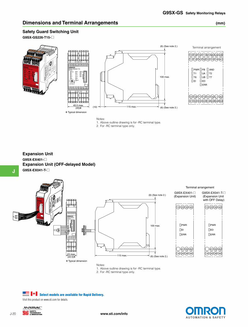
Dimensions and Terminal Arrangements (mm)
Notes:1. Above outline drawing is for -RC terminal type.2. For -RC terminal type only.
Safety Guard Switching UnitG9SX-GS226-T15-□
Notes:1. Above outline drawing is for -RC terminal type.2. For -RC terminal type only.
Expansion UnitG9SX-EX401-□Expansion Unit (OFF-delayed Model)G9SX-EX041-T-□
Terminal arrangement
T31 T32 T33T11
Y1 M1 M2T12 T61 T62 Y2 Y3
T21 T22X1 X2 X3 X4 S14 S24
T72T71 T41 T42
24VDC
T1
ERR
G9SX-GS226-T15
EI
T6
FB
ED
UA
PWR
OFF-DELAY
UB
0.2 00.3
0.40.5
0.60.7 1 1.5 2 3
457
1015
T2
T7
AND
UA UBY4 A1
S44 S54L1 A2
No.
(10) 115 max.
100 max.
(6) (See note 2.)
(6) (See note 2.)45.5 max.
(45)*
* Typical dimension
FB
UA
ED
UB
ERR
PWR
T1
EI
T6
AND
T2
T7
X4
T72
X1
T21
X2
T22 T71
X3 S14
T41
S24
T42
S44
L1
S54
A2
T33T32T31
T62T61T12T11 Y2 Y3 Y4 A1
Y1 M1 M2 UA UB
43332313
44342414A2X2A1
G9SX-EX40124VDC
23 max.(22.5)*
* Typical dimension
115 max.
100 max.
(6) (See note 2.)
(6) (See note 2.)
43332313
PWR
44
A2
14 24
A1
34
X2
EI
ERR
43332313
PWR
44
A2
14 24
A1
34
X2
ED
ERR
G9SX-EX041-T-@(Expansion Unit with OFF Delay)
G9SX-EX401-@(Expansion Unit)
Terminal arrangement
Select models are available for Rapid Delivery.Visit this product on www.sti.com for details.
J
J-21www.sti.com/info
S2
12
11 21
22
+24 V
S1
+24 V+24 V+24 V +24 V
+24 VNC
NC
(See note 2.)
(See note 2.)
NCNC NC NCNC NC
G9SX-BC202 (Unit 1)
Control circuit
G9SX-GS226-T15 (Unit 2)
ReceiverEmitter
GND
ReceiverEmitter
GND
+24 V
GND
M2
KM4
KM3
Auto
Manual
OFF
ANDT42T41T33T32T31Y4Y2T72T71T62T61M2M1Y3Y1T22T21T12T11A1
KM3
KM4
Control circuit
PLC etc.
UBUAX4X3X2X1L1
KM4KM3
S54S44S24S14A2
M1
KM1
KM2
KM2
KM1
Y1T33T32T31T22A1 T11 T12 T21
Emergency stop switch
X2X1L2L1S14 S24
KM1 KM2
A2
PLC etc.
Safety Sensor A Safety Sensor B
Feedback loop
Feedback Loop
Indicator(Diagnostic
check disabled)
Indicator(Diagnostic
check enabled)
Con
trol
out
put 2
Con
trol
out
put 1
Con
trol
out
put 1
Con
trol
out
put 2
G9SX-GS Safety Monitoring Relays
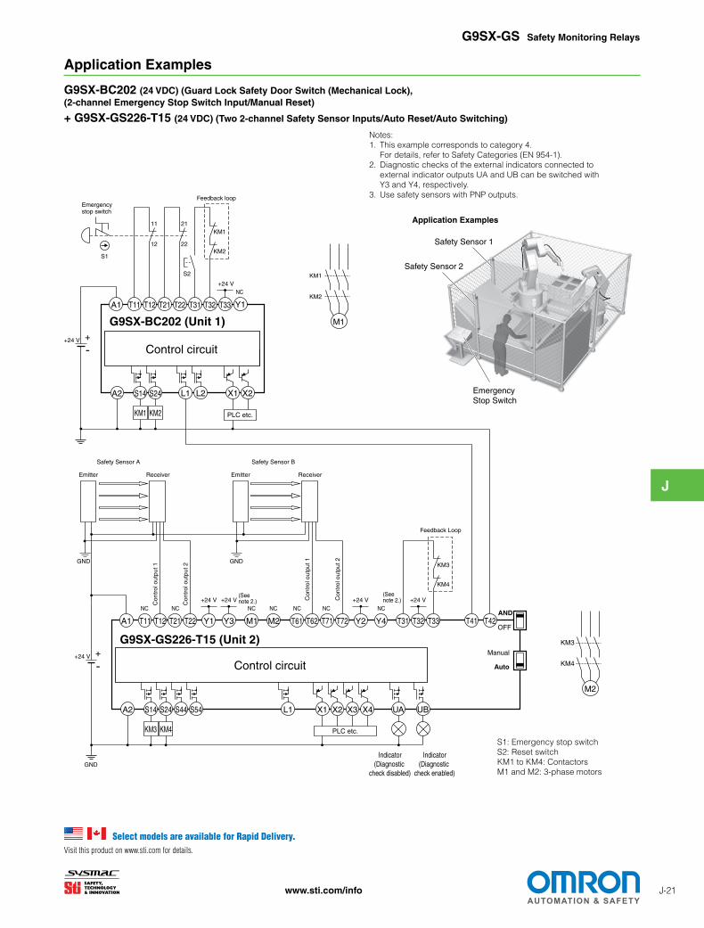
Application Examples
G9SX-BC202 (24 VDC) (Guard Lock Safety Door Switch (Mechanical Lock), (2-channel Emergency Stop Switch Input/Manual Reset)
+ G9SX-GS226-T15 (24 VDC) (Two 2-channel Safety Sensor Inputs/Auto Reset/Auto Switching)
Notes:1. This example corresponds to category 4.
For details, refer to Safety Categories (EN 954-1).2. Diagnostic checks of the external indicators connected to
external indicator outputs UA and UB can be switched with Y3 and Y4, respectively.
3. Use safety sensors with PNP outputs.
Application Examples
S1: Emergency stop switchS2: Reset switchKM1 to KM4: ContactorsM1 and M2: 3-phase motors
Emergency Stop Switch
Safety Sensor 1
Safety Sensor 2
Select models are available for Rapid Delivery.Visit this product on www.sti.com for details.
J
J-22 www.sti.com/info
S14A2 S24 L1 L2 X1 X2
T11A1 T12 T21 T22 T31 T32 T33 Y1
KM2
KM1
S2
12
11 21
22
+24 V
KM1 KM2
M1
KM2
KM1
PLC etc.
S1
KM4
KM3
+24 V
+24 V
+24 V
M2
KM4
KM3
KM4KM3 PLC etc.
NC
NC
NCNC
Feedback loop
Feedback loop
G9SX-BC202 (Unit 1)
Control circuit
S14A2 S24 S44 S54 L1 X3X2X1 X4 UA
T11A1 T12 T21 Y1 Y3T22 T61 T62M1 M2 T71 Y2 Y4T72 T31 T32 T33 T41 T42OFF
AND
Auto
Manual
G9SX-GS226-T15 (Unit 2)
Control circuit
23
24
11
12
11
12
S3
S421
22
Mode selector
Conveyor cart
S7
S6
+24 V
GND
UB
Emergency stop switch
+24 V (Seenote 2.)
(See note 2.)
S5
Cover
Indicator (Diagnostic
check enabled)
Indicator (Diagnostic
check disabled)
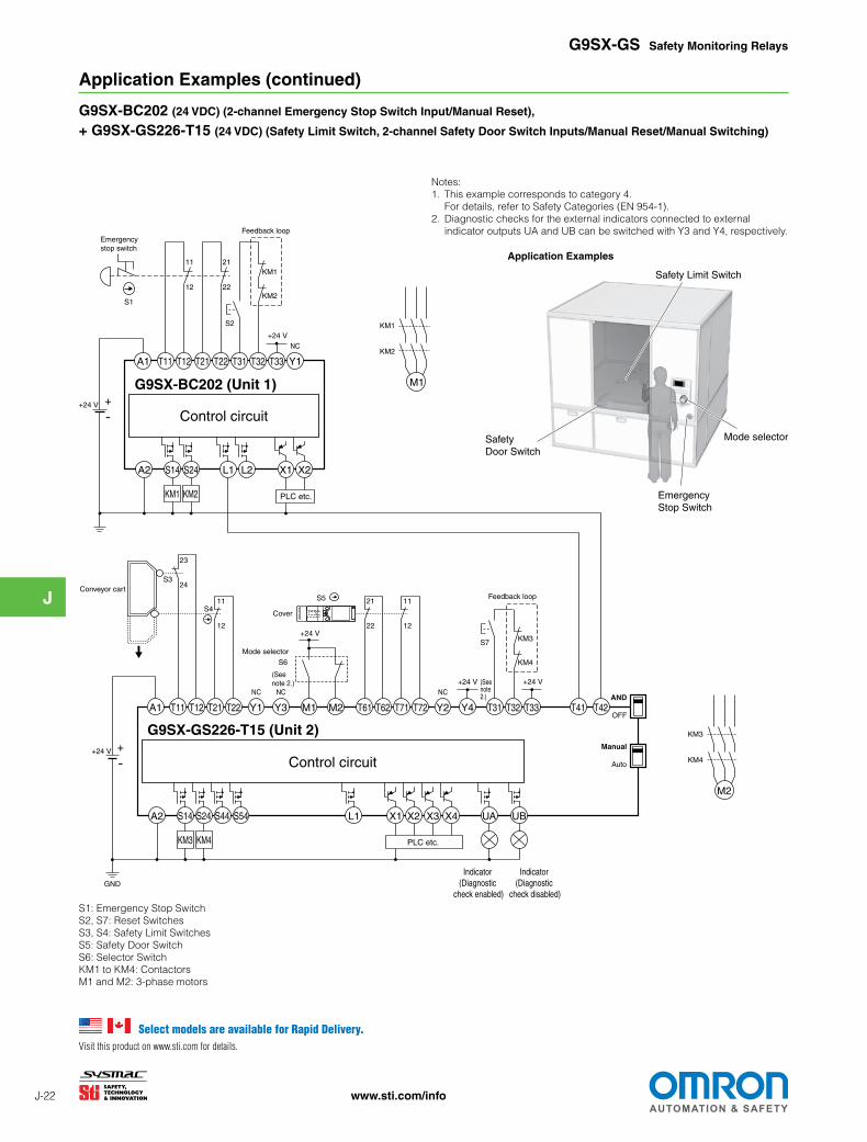
Application Examples (continued)
G9SX-BC202 (24 VDC) (2-channel Emergency Stop Switch Input/Manual Reset),
+ G9SX-GS226-T15 (24 VDC) (Safety Limit Switch, 2-channel Safety Door Switch Inputs/Manual Reset/Manual Switching)
Application Examples
G9SX-GS Safety Monitoring Relays
Notes:1. This example corresponds to category 4.
For details, refer to Safety Categories (EN 954-1).2. Diagnostic checks for the external indicators connected to external
indicator outputs UA and UB can be switched with Y3 and Y4, respectively.
S1: Emergency Stop SwitchS2, S7: Reset SwitchesS3, S4: Safety Limit SwitchesS5: Safety Door SwitchS6: Selector SwitchKM1 to KM4: ContactorsM1 and M2: 3-phase motors
Emergency Stop Switch
Mode selector
Safety Limit Switch
Safety Door Switch
Select models are available for Rapid Delivery.Visit this product on www.sti.com for details.
J
J-23www.sti.com/info
Emergency Stop Switch
Cover 1
Mode selector Safety Limit Switch
Cover 2
G9SX-GS Safety Monitoring Relays
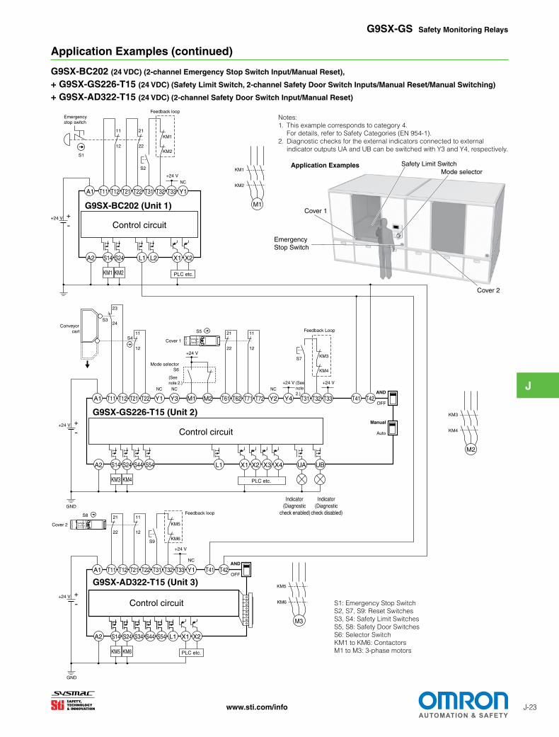
Application Examples (continued)
G9SX-BC202 (24 VDC) (2-channel Emergency Stop Switch Input/Manual Reset),
+ G9SX-GS226-T15 (24 VDC) (Safety Limit Switch, 2-channel Safety Door Switch Inputs/Manual Reset/Manual Switching)
+ G9SX-AD322-T15 (24 VDC) (2-channel Safety Door Switch Input/Manual Reset)
Notes:1. This example corresponds to category 4.
For details, refer to Safety Categories (EN 954-1).2. Diagnostic checks for the external indicators connected to external
indicator outputs UA and UB can be switched with Y3 and Y4, respectively.
Application Examples
S14A2 S24 L1 L2 X1 X2
T11A1 T12 T21 T22 T31 T32 T33 Y1
KM2
KM1
S2
12
11 21
22
+24 V
KM1 KM2
M1
KM2
KM1
PLC etc.
S1
KM4
KM3
+24 V
+24 V
M2
KM4
KM3
KM4KM3 PLC etc.
NC
NC
NCNC
Feedback loop
Feedback Loop
G9SX-BC202 (Unit 1)
Control circuit
S14A2 S24 S44 S54 L1 X3X2X1 X4 UA
T11A1 T12 T21 Y1 Y3T22 T61 T62M1 M2 T71 Y2 Y4T72 T31 T32 T33 T41 T42OFF
AND
Auto
Manual
G9SX-GS226-T15 (Unit 2)
Control circuit
23
24
11
12
11
12
S3
S421
22
Conveyor cart
S7
+24 V
GND
UB
Emergency stop switch
+24 V (See note 2.)
S5
Cover 1
+24 V
Mode selectorS6
(See note 2.)
S14A2 S24 S34 S44 S54 L1 X1 X2
T11A1 T12 T21 T22 T31 T32 T33 Y1 T41 T42
G9SX-AD322-T15 (Unit 3)
Control circuit
KM6
KM5
+24 V
Feedback loop
+24 V
KM5 KM6
M3
KM6
KM5
OFF
AND
PLC etc.
NC
GND
S9
11
12
21
22
S8
Cover 2
Indicator (Diagnostic
check enabled)
Indicator (Diagnostic
check disabled)
S1: Emergency Stop SwitchS2, S7, S9: Reset SwitchesS3, S4: Safety Limit SwitchesS5, S8: Safety Door SwitchesS6: Selector SwitchKM1 to KM6: ContactorsM1 to M3: 3-phase motors
J
J-24 www.sti.com/info
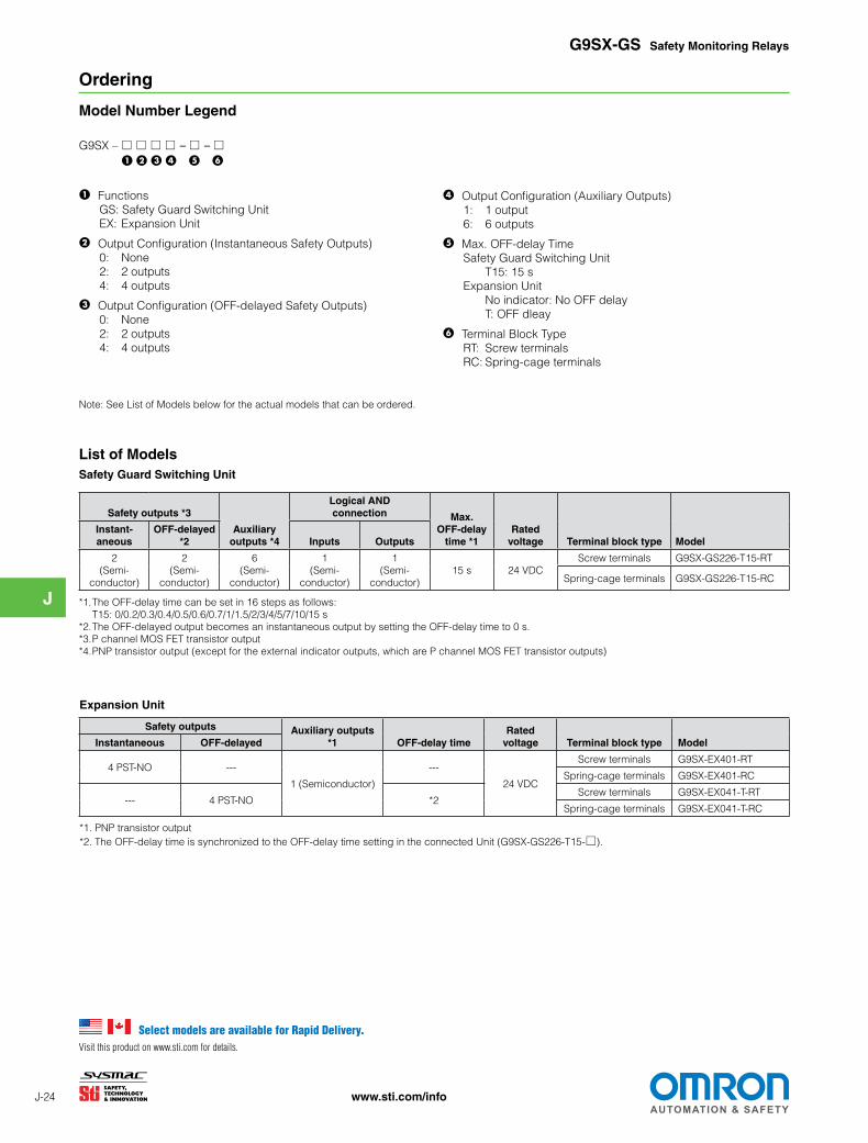
Ordering
Model Number Legend
G9SX – □ □ □ □ – □ – □ 1234 5 6
1 FunctionsGS: Safety Guard Switching UnitEX: Expansion Unit
2 Output Configuration (Instantaneous Safety Outputs)0: None2: 2 outputs4: 4 outputs
3 Output Configuration (OFF-delayed Safety Outputs)0: None2: 2 outputs4: 4 outputs
4 Output Configuration (Auxiliary Outputs)1: 1 output6: 6 outputs
5 Max. OFF-delay TimeSafety Guard Switching Unit T15: 15 sExpansion Unit No indicator: No OFF delay T: OFF dleay
6 Terminal Block TypeRT: Screw terminalsRC: Spring-cage terminals
G9SX-GS Safety Monitoring Relays
List of ModelsSafety Guard Switching Unit
*1. The OFF-delay time can be set in 16 steps as follows: T15: 0/0.2/0.3/0.4/0.5/0.6/0.7/1/1.5/2/3/4/5/7/10/15 s
*2. The OFF-delayed output becomes an instantaneous output by setting the OFF-delay time to 0 s.*3. P channel MOS FET transistor output*4. PNP transistor output (except for the external indicator outputs, which are P channel MOS FET transistor outputs)
Safety outputs *3
Auxiliary outputs *4
Logical AND connection Max.
OFF-delay time *1
Rated voltage Terminal block type Model
Instant- aneous
OFF-delayed *2 Inputs Outputs
2 (Semi-
conductor)
2 (Semi-
conductor)
6 (Semi-
conductor)
1 (Semi-
conductor)
1 (Semi-
conductor)15 s 24 VDC
Screw terminals G9SX-GS226-T15-RT
Spring-cage terminals G9SX-GS226-T15-RC
Expansion Unit
*1. PNP transistor output*2. The OFF-delay time is synchronized to the OFF-delay time setting in the connected Unit (G9SX-GS226-T15-□).
Safety outputs Auxiliary outputs *1 OFF-delay time
Rated voltage Terminal block type ModelInstantaneous OFF-delayed
4 PST-NO ---
1 (Semiconductor)
---
24 VDC
Screw terminals G9SX-EX401-RT
Spring-cage terminals G9SX-EX401-RC
--- 4 PST-NO *2Screw terminals G9SX-EX041-T-RT
Spring-cage terminals G9SX-EX041-T-RC
Note: See List of Models below for the actual models that can be ordered.
Select models are available for Rapid Delivery.Visit this product on www.sti.com for details.