Embed Size (px)
Citation preview
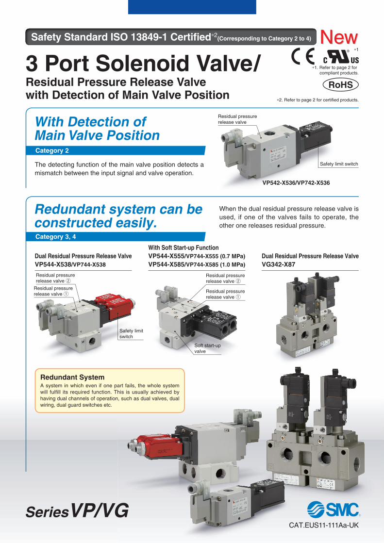
3 Port Solenoid Valve/Residual Pressure Release Valvewith Detection of Main Valve Position
Residual pressure
release valve
Residual pressure release valve q
Residual pressure release valve q
Residual pressure release valve w
Residual pressure release valve w
Safety limit switch
Safety limit
switch
With Detection of Main Valve Position
The detecting function of the main valve position detects a
mismatch between the input signal and valve operation.
Redundant system can be constructed easily.
Redundant SystemA system in which even if one part fails, the whole system
will fulfill its required function. This is usually achieved by
having dual channels of operation, such as dual valves, dual
wiring, dual guard switches etc.
VP542-X536/VP742-X536
Soft start-up
valve
Safety Standard ISO 13849-1 Certifi ed∗2(Corresponding to Category 2 to 4)
Category 2
Category 3, 4
Dual Residual Pressure Release Valve
VP544-X538/VP744-X538
With Soft Start-up Function
VP544-X555/VP744-X555 (0.7 MPa)
VP544-X585/VP744-X585 (1.0 MPa)
Dual Residual Pressure Release Valve
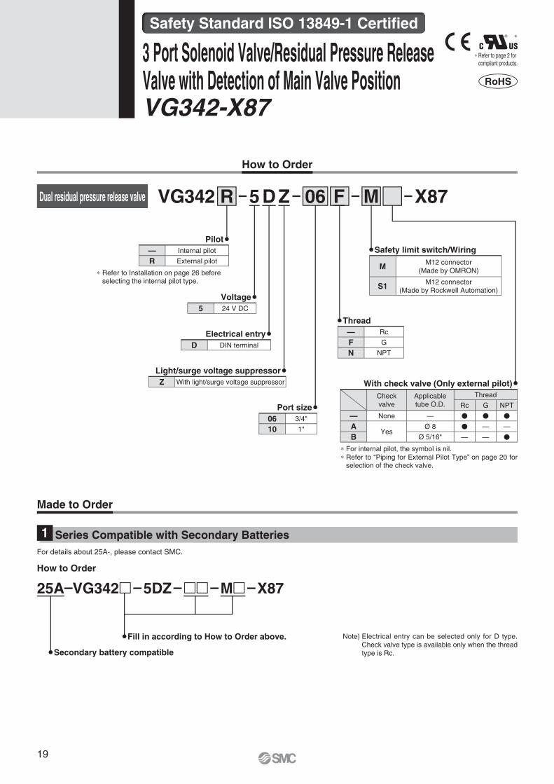
VG342-X87
When the dual residual pressure release valve is
used, if one of the valves fails to operate, the
other one releases residual pressure.
SeriesVP/VGCAT.EUS11-111Aa-UK
RoHS
∗1. Refer to page 2 for
compliant products.
∗2. Refer to page 2 for certified products.
® ∗1
NewNew

2(A)
3(R)3(R)
1(P)
P1
P2
Throttle Main valve Valve 1 Valve 2
Soft start-up
valve
Safety limit
switchSafety limit
switch
Soft start-up
valve
Made by Rockwell AutomationMade by OMRON
Soft start-up valve: ON
Valve 1, Valve 2: ON
Ou
tpu
t p
ressu
re P
2
Time
P1
1/2P1
0
Soft start-up valve : OFF
Valve 1, Valve 2: ON
P2 reaches half of P1, and then the main valve of the soft start-up valve turns on.
Start supplying flow ad-justed air with the throt-tle by energising valve 1 and valve 2.
Output Pressure (P2) vs Time Graph
The detecting function of the main valve position detects a
mismatch between the input signal and valve operation.
Category 2 Safety function can be accomplished by single channel and is automatically
checked.
Category 3 It has redundancy so there is no loss of safety function with a single failure.
The safety function must be checked before each use. An accumulation of
undetected faults can cause loss of safety function.
Category 4 It has redundancy so there is no loss of safety function with a single failure. The
safety function must be checked before each use. An accumulation of undetected
faults does not affect the safety function. (Higher DC and MTTFd than Category 3.)
Residual pressure release valve
With Detection of Main Valve Position (Category 2)
Input equipment (I) : Detection equipment (sensor) of starting event
Logical operation equipment (L) : Relay sequence circuit, PLC control program
Output equipment (O) : Solenoid valve, Electromagnetic switch, Output relay
Recommended valve : VP542/742-X536
Input equipment (I1, I2): Detection equipment (sensor) of starting event
Logical operation equipment (L1, L2): Relay sequence circuit, PLC control program
Output equipment (O1, O2): Solenoid valve, Electromagnetic switch, Output relay
Recommended valve: VP544/744-X538, VG342-X87
Output signal
Monitoring
Output signal
Input signalIInput equipment
OOutput equipment
OTEOutput of test result
LLogical operation
equipment
TETesting equipment
When the dual residual pressure release valve is used, if one of the
valves fails to operate, the other one releases residual pressure.
Redundant system can be constructed easily. (Category 3, 4)
Output signal
Output signal
Monitoring
Monitoring
Cross monitoring
Input signal
Input signal
I1Input equipment
I2Input equipment
O1Output equipment
O2Output equipment
L1Logical operation
equipment
L2Logical operation
equipment
With soft start-up function (-X555/X585)
Safety limit switch can be selected.
Safety limit switchMain valve Rod
VP544-X538VP542-X536
Residual pressure release valve w
∗ This product is component which is a part of a safety system and safety equipment is not guaranteed by this single unit alone.
VP544-X555
VP544-X585
Residual pressurerelease valve q
� A function to gradually increase the initial pressure of the pneumatic system has been added to the dual residual pressure release valve.
� Fixed orifi ce and variable throttle are available as a throttle for adjusting the pressure increase. (Ø 1, Ø 1.5, Ø 2)
Conduit (VP series only) and
M12 connector (4 pin) types
are available.
M12 connector with 6 pins is
available.
q The main valve position is detected by transferring the
main valve movement directly to the reed safety limit switch
with the rod.
w Long service life: B10d: 10 million times∗e The return spring releases the residual pressure securely
regardless of pressure level.
∗ For VP�-X536/X538/X555, safety limit switch made by OMRON
Highly reliable construction
1
3 Port Solenoid Valve/Residual Pressure Release Valve with Detection of Main Valve Position Series VP/VG
Safety Standard ISO 13849-1 Certifi ed

For details about Safety Standard
ISO 13849-1, refer to “machinery
directive 2006/421EC. Safety
control system standard EN ISO
13849-1” on the SMC website
www.smc.eu.
Series CategoryPort
sizeThread
Flow rate characteristics
C [dm3/(s·bar)]/Q [l/min (ANR)]∗ 1 2 (P A)
5 10 15 20 25
Residual Pressure
Release Valve
VP542-X5362
3/8"Rc,
G,
NPTResidual Pressure
Release Valve
VP742-X5361/2"
Dual Residual Pressure
Release Valve
VP544-X538
3, 4
3/8"Rc,
G,
NPTDual Residual Pressure
Release Valve
VP744-X5381/2"
Dual Residual Pressure Release
Valve with Soft Start-up Function
VP544-X555/VP544-X5853/8"
Rc,
G,
NPTDual Residual Pressure Release
Valve with Soft Start-up Function
VP744-X555/ VP744-X5851/2"
Dual Residual Pressure
Release Valve
VG342-X873/4"
Rc,
G,
NPT
Can be connected to Modular type
F.R.L. units.
Applicable models∗�VP544/744-X538�VP544/744-X555
�VP544/744-X585
Page 17
X585
ure
∗ Only port size 3/4"
85
Standards and Enclosure
Series Variations
Dual residual pressure
release valve with soft
start-up function
Filter regulator
(Optional
accessory)
Series CategorySafety limit switch
manufacturer
Standards
EnclosureMachinery Directive 2006/42/EC
CE cUL RoHSHarmonised
standards
EN ISO 13849-1: 2008
EN ISO 13849-2: 2008
EN ISO 4414:
2010
Residual Pressure
Release Valve
VP542/742-X536
2
OMRON Corporation
IP65
Rockwell Automation, Inc.
Dual Residual Pressure
Release Valve
VP544/744-X538
3, 4
OMRON Corporation
IP65
Rockwell Automation, Inc.
Dual Residual Pressure Release Valve
with Soft Start-up Function
VP544/744-X555
VP544/744-X585
3, 4
OMRON Corporation
IP65
Rockwell Automation, Inc.
Dual Residual Pressure
Release Valve
VG342-X87
3, 4
OMRON Corporation∗
IP40
Rockwell Automation, Inc.
Page 3
Page 3
Page 3
Page 19
∗ These values have been calculated according to ISO 6358 and indicate the fl ow rate under standard conditions with an inlet pressure of 0.6 MPa (relative pressure)
and a pressure drop of 0.1 MPa
∗ Please contact SMC for the
VP542/742-X536.
26.6/
5864
2
5
9.8/2203
8.9/2085
15.1/3637
6.5/1461
10.3/2315
5.2/1157
2
3 Port Solenoid Valve/Residual Pressure Release Valve with Detection of Main Valve Position Series VP/VG
Safety Standard ISO 13849-1 Certifi ed

How to Order
Body
2 Body ported
4 Base mounted
Voltage
5 24 V DC
Maximum operating
pressure
X555 0.7 MPa
X585 1.0 MPa
Light/surge voltage suppressor
Z With light/surge voltage suppressor
Series
5 VP500
7 VP700
Pilot
Internal pilot
R External pilot
∗ Refer to Installation on page 18 before selecting the internal pilot type.
Electrical entry
D DIN terminal
Y DIN (EN 175301-803) terminal
∗ Refer to page 18 for details about type Y.
Port size
Port size VP500 VP700
03 3/8" � —
04 1/2" — �
Thread
— Rc
F G
N NPT
Safety limit switch/Wiring
— G 1/2 (Made by OMRON)
M M12 connector (Made by OMRON)
S1M12 connector
(Made by Rockwell Automation)
With check valve (Only external pilot)
Check
valve
Applicable
tube O.D.
Thread
Rc G NPT
— None — � � �
AYes
Ø 6 � — —
B Ø 1/4∗ — — �
∗ For internal pilot, the symbol is nil.
∗ Refer to “Piping for External Pilot Type” on page 4 for selection of the check valve.
Throttle
— Variable throttle
10 Ø 1 fi xed orifi ce
15 Ø 1.5 fi xed orifi ce
20∗ Ø 2 fi xed orifi ce
∗ VP700 only
3 Port Solenoid Valve/Residual Pressure Release Valve with Detection of Main Valve Position VP-X536, X538, X555, X585
X536
X538
X555
25A–VP�4 ��– 5DZ1 – ��� – ��� –
Series Compatible with Secondary Batteries1
Made to Order
For details about 25A-, please consult SMC.
Secondary battery compatible
Dual residual pressure release valve
Dual residual pressure release
valve with soft start-up function
Residual pressure release valve VP
VP
4
4
4
25
5
5
D
D
D
5 ZR
R
M
M
M
1
1
1
03
03
03
X536
X538
X555VP
4
4
Z
Z
5
5
How to Order
Note) Electrical entry can be selected only for D type.
Check valve type is available only when the thread
type is Rc.
Safety Standard ISO 13849-1 Certifi ed
Fill in according to How to Order above.
F
F
F
∗ Refer to page 2 for
compliant products.
∗
X536
3

Model
VP�42-X536
VP�44-X538
VP�44-X555
VP�42R-X536
VP�44R-X538
VP�44R-X555
VP�44-X585 VP�44R-X585
Fluid Air
Type of actuation N.C. (Spring return)
Operation Internal pilot External pilot Internal pilot External pilot
Operating pressure range 0.25 to 0.7 MPa 0.25 to 1.0 MPa
External pilot pressure — 0.25 to 0.7 MPa (Same as operating pressure)
Maximum operating frequency 30 times/minute
Minimum operating frequency 1 time/week
Operating and ambient temperature -10 to 50 °C (No freezing)
Ambient humidity 20 to 90 %RH (No condensation)
Manual override None
Pilot exhaust Individual exhaust
Lubrication Not required
Mounting orientation Unrestricted
Impact/Vibration resistance 150/30 m/s2
Enclosure IP65
Operating environment Indoors
B10d (MTTFd calculation)10000000 times (for the safety limit switch made by OMRON)
1000000 times (for the safety limit switch made by Rockwell Automation)1000000 times
Internal Pilot Type
CautionEven when the inlet pressure is within the operat-
ing pressure range, restricted piping, etc., may
cause reduced flow on the inlet side, leading to
the valve not operating properly. Refer to Installa-
tion in the Specifi c Product Precautions for details.
Piping for External Pilot Type
CautionThe product may not operate when the external pilot
pressure is insuffi cient due to simultaneous opera-
tion or restricted air piping. In this case, use the
check valve (AKH series) with the external pilot port,
change the piping size or adjust the set pressure to
provide a constant pressure of 0.25 MPa or more.
Valve Specifi cations
Series
Flow rate characteristicsWeight
[g]1 2 (P A) 2 3 (A R)
C [dm3/(s·bar)] b Cv Q [l/min (ANR)]∗ C [dm3/(s·bar)] b Cv Q [l/min (ANR)]∗VP542-X536 8.9 0.16 2.2 2085 8.9 0.20 2.1 2132 350
VP742-X536 15.1 0.21 3.6 3637 15.3 0.22 3.7 3707 590
VP544-X538 6.5 0.08 1.3 1461 6.7 0.10 1.3 1521 930
VP744-X538 10.3 0.08 2.3 2315 9.7 0.08 2.1 2180 1510
VP544-X555
VP544-X5855.2 0.06 1.1 1157 6.7 0.10 1.3 1521 1105
VP744-X555
VP744-X5859.8 0.08 2.1 2203 9.7 0.08 2.1 2180 2000
Flow Rate Characteristics / Weight
Electrical entry DIN terminal
Rated voltage 24 V DC
Allowable voltage fl uctuation ±10 %
Power consumption 0.45 W
Surge voltage suppressor Varistor
Indicator LED
Manufacturer OMRON Rockwell Automation
Electrical wiring G 1/2, M12 connector M12 connector
Contact resistance 25 mΩ or less 50 mΩ or less
Min. applicable load 5 V DC, 1 mA (Load resistance) 5 V DC, 5 mA (Load resistance)
Max. voltage 24 V DC
Max. load current 50 mA
Max. load inductance 0.5 H
Insulation voltage 300 V 600 V
Protection against electric shock Class II (EN60947-5-1: 2004)
Solenoid Specifi cations Safety Limit Switch Specifi cations
Needle Valve / Flow Rate Characteristics (VP544/744-X555)
600
500
400
300
200
100
00 0.5 1 1.5 2 2.5 3 3.5 4
Number of needle rotations (Turns)
Flo
w r
ate
[l/m
in (
AN
R)]
0.25 MPa
0.7 MPa
Ø 2Ø 1.5Ø 1
0.5 MPa
∗ These values have been calculated according to ISO 6358 and indicate the fl ow rate under standard
conditions with an inlet pressure of 0.6 MPa (relative pressure) and a pressure drop of 0.1 MPa
4
Safety Standard ISO 13849-1 Certifi ed 3 Port Solenoid Valve/Residual Pressure Release Valve with Detection of Main Valve Position VP-X536, X538, X555, X585
VP
50
0/7
00
X5
36
X5
38
VG
342
X87
Spec
ific P
rodu
ctPr
ecau
tions
Sy
mb
ols
Sym
bo
lsSp
ecifi
c Pro
duct
Prec
autio
nsO
ptio
nal
Acc
esso
ries
X555
X585

3(R)
3(R)
1(P) 1(P) 1(P)
1(P) 1(P) 1(P)
X X
X
3(R)1(P)
2(A)
(31)e
(11)q
r(32)
w(12)
3(R)1(P)
2(A)
(31)e
(11)q
r(32)
w(12)
3(R)1(P)
2(A)
(31)e
(11)q
r(32)
w(12)
3(R)
2(A)
(31)e
(11)q
r(32)
w(12)
(31)e
(11)q
r(32)
w(12)
(31)e
(11)q
r(32)
w(12)
3(R)
2(A)
(31)e
(11)q
r(32)
w(12)
3(R)
2(A)
(31)e
(11)q
r(32)
w(12)
3(R)(31)e
(11)q
r(32)
w(12)
3(R)(31)e
(11)q
r(32)
w(12)
3(R)(31)e
(11)q
r(32)
w(12)
X
2(A)
3(R)
3(R)
(31)e
(11)q
r(32)
w(12)
(31)e
(11)q
r(32)
w(12)
2(A)
3(R)
3(R)
(31)e
(11)q
r(32)
w(12)
(31)e
(11)q
r(32)
w(12)
2(A)
X X
Safety limit switch terminal [N.C.]
M12 connector pin number
G 1/2 terminal number
Symbols
Terminal/Pin Numbers (Built-in switch 2N.C.)Symbol
VP544(R)/744(R)-X538
VP544(R)/744(R)-X555
VP544(R)/744(R)-X585
M12 connector
pin numberWiring specifi cation
q
w
e
r
G 1/2
terminal numberWiring specifi cation
(11)
3231
1211(12)
(31)
(32)
VP542(R)/742(R)-X536
Made by OMRON
Safety limit switch
Internal pilot
Internal pilot
Internal pilot
External pilot
External pilot
External pilot
External pilot/With check valve
External pilot/With check valve
External pilot/With check valve
(32)(12)
(31)(11)
5
VP-X536, X538, X555, X585

3(R)
3(R)
wq e
yt r
3(R)1(P)
2(A)
wq e
yt r
3(R)
2(A)
wq e
yt r
3(R)
wq e
yt r
3(R)1(P)
2(A)
wq e
yt r
3(R)1(P)
2(A)
X X
X X
wq e
yt r
3(R)
2(A)
wq e
yt r
3(R)
wq e
yt r
3(R)
2(A)
wq e
yt r
3(R)
wq e
yt r
wq e
yt r
1(P)
1(P) 1(P) 1(P)
2(A)
3(R)
3(R)wq e
yt r
wq e
yt r
1(P)
2(A)
3(R)
3(R)wq e
yt r
wq e
yt r
1(P)
2(A)
XX
Safety limit switch terminal [N.C.]
M12 connector pin number
Symbols
VP544(R)/744(R)-X538
Pin Numbers (Built-in switch 3N.C.)
M12 connector
pin numberWiring specifi cation
q
t
w
y
e
r
Internal pilot
Internal pilot
Internal pilot
External pilot
External pilot
External pilot
External pilot/With check valve
External pilot/With check valve
External pilot/With check valve
VP542(R)/742(R)-X536
Made by Rockwell Automation
Safety limit switch
Symbol
VP544(R)/744(R)-X555
VP544(R)/744(R)-X585
6
Safety Standard ISO 13849-1 Certifi ed 3 Port Solenoid Valve/Residual Pressure Release Valve with Detection of Main Valve Position VP-X536, X538, X555, X585
VP
50
0/7
00
X5
36
X5
38
VG
342
X87
Spec
ific P
rodu
ctPr
ecau
tions
Sy
mb
ols
Sym
bo
lsSp
ecifi
c Pro
duct
Prec
autio
nsO
ptio
nal
Acc
esso
ries
X555
X585

4.5
A
(Max. 10)
26
3.5
732
117.754.9
30.7
45
2 x Ø 4.2
(For mounting)
31
216.1
133.2
22.1
25.2
70.8
63.3
31.5
40
4
216.7
131.723.5
8
3/8"
[1(P), 3(R) port]
Vent port
(Ø 6.2)
M12 connector
2 x Ø 4.2
(For mounting)
Safety limit switch (made by Rockwell Automation)
Part number: 440P-CDPB03R6
(31.5)(Distance between ports)
Applicable cable O.D.
Ø 3.5 to Ø 7
Port size: 1/8" (Without check valve)
Applicable tube O.D.: Ø 6, Ø 1/4" (With check valve)
(External pilot port)
3/8"
[2(A) port]
(22.9
)
(With
check
valv
e)
4.5
(25
.7)
A
45
(Max. 10)
26
3.5
732
Port size: 1/8" (Without check valve)
Applicable tube O.D.: Ø 6, Ø 1/4" (With check valve)
(External pilot port)312 x Ø 4.2
(For mounting)
201.8
118.9
G 1/2
(14)202.4
117.423.5
70
.8
63
.3
31
.5
40
4
Applicable cable O.D.
Ø 3.5 to Ø 7Safety limit switch (made by OMRON)
Part number: D4N-2B31 (G 1/2)
: D4N-9B31 (M12 connector)2 x Ø 4.2
(For mounting)
103.454.9
30.7Vent port
(Ø 6.2)
3/8"
[1(P), 3(R) port]
22.1
(31.5)(Distance between ports)
3/8"
[2(A) port]
(M12 connector)
(22
.9)
(With
check
valv
e)
Dimensions
VP542(R)-5D Y Z1-03�-�-X536
VP542(R)-5D Y Z1-03�-M�-X536
VP542(R)-5D Y Z1-03�-S1�-X536
Residual Pressure Release Valve (-X536)
Made by OMRON
Safety limit switch
Made by Rockwell Automation
Safety limit switch
Pin
number
View A
For M12 connector
View A
M12 connector
Pin
number
7
VP-X536

4.5 7.5
44.5
(Max. 10) 224.2
108.4
A
940
63
56
.5
224.8
128.931 (14)
9.4
38
.5
88
.8
81
.3
107.973.5
42
(34
.7)
G 1/2
Ø 5.2
(For mounting)
Applicable cable O.D.
Ø 3.5 to Ø 7
Vent port
(Ø 6.2)1/2"
[1(P), 3(R) port]
(43) (Distance between ports)
3.5
20.5
Ø 5.2
(For mounting)
33
3.5
Port size: 1/8" (Without check valve)
Applicable tube O.D.: Ø 6, Ø 1/4" (With check valve)
(External pilot port)
1/2"
[2(A) port]
(22
.9)
(With
ch
eck v
alv
e)
(M12 connector)
Safety limit switch (made by OMRON)
Part number: D4N-2B31 (G 1/2)
: D4N-9B31 (M12 connector)
88.8
81.3
Applicable cable O.D.
Ø 3.5 to Ø 7
9.4
38.5
33
4.5
(Max. 10)
7.5
2 x Ø 5.2
(For mounting)
41
A
63
56.5
2 x Ø 5.2
(For mounting)
940
73.5
42Vent port
(Ø 6.2)
1/2"
[1(P), 3(R) port]
(43)(Distance between ports)
34.2
238.5
143.2
24
8
239.1
143.231
122.2
Port size: 1/8" (Without check valve)
Applicable tube O.D.: Ø 6, Ø 1/4" (With check valve)
(External pilot port)
1/2"
[2(A) port]
Safety limit switch (made by Rockwell Automation)
Part number: 440P-CDPB03R6
(22.9
)
(With c
heck v
alv
e)
M12 connector
Dimensions
VP742(R)-5DY Z1-04�-�-X536
VP742(R)-5DY Z1-04�-M�-X536
VP742(R)-5DY Z1-04�-S1�-X536
Residual Pressure Release Valve (-X536)
View A
For M12 connector
Pin
number
View A
M12 connector
Pin
number
Made by OMRON
Safety limit switch
Made by Rockwell Automation
Safety limit switch
8
Safety Standard ISO 13849-1 Certifi ed 3 Port Solenoid Valve/Residual Pressure Release Valve with Detection of Main Valve Position VP-X536
VP
50
0/7
00
X5
36
X5
38
VG
342
X87
Spec
ific P
rodu
ctPr
ecau
tions
Sy
mb
ols
Sym
bo
lsSp
ecifi
c Pro
duct
Prec
autio
nsO
ptio
nal
Acc
esso
ries
X555
X585

11.3
97.3
18 2
933.5
Applicable cable O.D.
Ø 3.5 to Ø 7
28.53/8"
[2(A) port] 17.5
91.5
75.5
5472 x Ø 5.2
(For mounting)
(Max. 10)
Channel 2
Channel 1
201.8 (14)
(90.4)
34
17
.5
57
28.5
791
04
.8
Vent port
(Ø 6.2)
A
112 90.4
62.5
29
17.5
28.2
2 x 3/8"
[3(R) port]
(59.7)
G 1/2
3/8"
[1(P) port]
8
(22.9)
(With check valve)Port size: 1/8" (Without check valve)
Applicable tube O.D.: Ø 6, Ø 1/4" (With check valve)
(External pilot port)
Safety limit switch (made by OMRON)
Part number: D4N-2B31 (G 1/2)
: D4N-9B31 (M12 connector)
(M12 connector)
Dimensions
VP544(R)-5D Y Z1-03�-�-X538
VP544(R)-5D Y Z1-03�-M�-X538
Dual Residual Pressure Release Valve (-X538)
View A
For M12 connector
Pin
number
Made by OMRON
Safety limit switch
9
VP-X538

11.3
97.3
18 2
933.5
Applicable cable O.D.
Ø 3.5 to Ø 7
216.1
91.5
75.5
8(104.7)5472 x Ø 5.2
(For mounting)
(Max. 10)
62.5
29
17.5
59.2
28.2
28.53/8"
[2(A) port] 17.5
Channel 2
Channel 1
34
17
.5
3/8"
[1(P) port]
104.7112
57
28.5
791
04
.8
Vent port
(Ø 6.2)
A
2 x 3/8"
[3(R) port]M12 connector
Port size: 1/8" (Without check valve)
Applicable tube O.D.: Ø 6, Ø 1/4" (With check valve)
(External pilot port)
Safety limit switch (made by Rockwell Automation)
Part number: 440P-CDPB03R6
(22.9)
(With check valve)
Dimensions
VP544(R)-5DY Z1-03�-S1�-X538
Dual Residual Pressure Release Valve (-X538)
View A
M12 connector
Pin
number
Made by Rockwell Automation
Safety limit switch
10
Safety Standard ISO 13849-1 Certifi ed 3 Port Solenoid Valve/Residual Pressure Release Valve with Detection of Main Valve Position VP-X538
VP
50
0/7
00
X5
36
X5
38
VG
342
X87
Spec
ific P
rodu
ctPr
ecau
tions
Sy
mb
ols
Sym
bo
lsSp
ecifi
c Pro
duct
Prec
autio
nsO
ptio
nal
Acc
esso
ries
X555
X585

9.5
(14)(Max. 10)
18
401/2"
[2(A) port]
77.5
36
(70.7)
27.2
18
G 1/2
2 x 1/2"
[3(R) port]
113.5
94.5
224.2
(88.9)
2 x Ø 6.2
(For mounting)
67 6.5Applicable cable O.D.
Ø 3.5 to Ø 7
117.3
1621
41.5
36
99
224.8
88.980
40
(22.9)
(With check valve)
12
4.8
36
18
1/2"
[1(P) port]
A
Vent port
(Ø 6.2)
Channel 2
Channel 1
Port size: 1/8" (Without check valve)
Applicable tube O.D.: Ø 6, Ø 1/4" (With check valve)
(External pilot port)
(M12 connector)
Safety limit switch (made by OMRON)
Part number: D4N-2B31 (G 1/2)
: D4N-9B31 (M12 connector)
Dimensions
VP744(R)-5D Y Z1-04�-�-X538
VP744(R)-5D Y Z1-04�-M�-X538
Dual Residual Pressure Release Valve (-X538)
Pin
number
View A
For M12 connector
Made by OMRON
Safety limit switch
11
VP-X538

18
9.5
117.3
16
21 3
641.5
Applicable cable O.D.
Ø 3.5 to Ø 7
Channel 2
Channel 177.5
36
70.2
27.2
18
2 x 1/2"
[3(R) port]
113.5
94.5
8238.5(Max. 10)
(103.2)
6.5672 x Ø 6.2
(For mounting)
1/2"
[2(A) port]
40
99
103.2135.9
80
40
1/2"
[1(P) port]
36
18
12
4.8
(22.9)
(With check valve)
Vent port
(Ø 6.2)
A
Port size: 1/8" (Without check valve)
Applicable tube O.D.: Ø 6, Ø 1/4" (With check valve)
(External pilot port)
Safety limit switch (made by Rockwell Automation)
Part number: 440P-CDPB03R6
M12 connector
Dimensions
VP744(R)-5DY Z1-04�-S1�-X538
Dual Residual Pressure Release Valve (-X538)
Pin
number
View A
M12 connector
Made by Rockwell Automation
Safety limit switch
12
Safety Standard ISO 13849-1 Certifi ed 3 Port Solenoid Valve/Residual Pressure Release Valve with Detection of Main Valve Position VP-X538
VP
50
0/7
00
X5
36
X5
38
VG
342
X87
Spec
ific P
rodu
ctPr
ecau
tions
Sy
mb
ols
Sym
bo
lsSp
ecifi
c Pro
duct
Prec
autio
nsO
ptio
nal
Acc
esso
ries
X555
X585

62.5
33.5
Applicable cable O.D.
(Ø 3.5 to Ø 7)
35
15
93.8
90.428.5(22.9)
(With check valve) 202.4
3/8"
[1(P) port]
(14)201.8(Max. 10)
(90.4) 8
125
109
547
(Variable throttle type)
75
.510
1.3
96
62.5
2 x 3/8"
[3(R) port]
G 12
56.2
24.2
Vent port
(Ø 6.4)
15.5
15
(15)
28.5
30
.5
24
.2
15
(15)
3/8"
[2(A) port]
Port size: 1/8" (Without check valve)
Applicable tube O.D.: Ø 6, Ø 1/4" (With check valve)
(External pilot port)
2 x Ø 5.2
(For mounting)
(M12 connector)
Vent port
(Ø 6.2)
A
Safety limit switch (made by OMRON)
Part number: D4N-2B31 (G 1/2)
: D4N-9B31 (M12 connector)
Dimensions
VP544(R)-5D Y Z1-03�-��-X555/X585
VP544(R)-5D Y Z1-03�-M��-X555/X585
Dual Residual Pressure Release Valve with Soft Start-up Function (-X555/X585)
Pin
number
View A
For M12 connector
Made by OMRON
Safety limit switch
13
VP-X555, X585

Vent port
(Ø 6.2)
62.5
33.5
35
8
125
109
75
.510
1.3
96
62.5
55.7
24.2
15.5
15
28.5
30
.5
24
.2
15
(Max. 10)
(22.9)
(With check valve)
(15)
3/8"
[2(A) port]
Safety limit switch (made by Rockwell Automation)
Part number: 440P-CDPB03R6
A
2 x 3/8"
[3(R) port]
M12 connector
Vent port
(Ø 6.4)
2 x Ø 5.2
(For mounting)
(Variable throttle type)
Applicable cable O.D.
(Ø 3.5 to Ø 7)
Port size: 1/8" (Without check valve)
Applicable tube O.D.: Ø 6, Ø 1/4" (With check valve)
(External pilot port)
3/8"
[1(P) port]
(15)
216.1
(90.4)
8 93.8
15
90.428.5
216.7
Dimensions
VP544(R)-5DY Z1-03�-S1��-X555/X585/X585
Dual Residual Pressure Release Valve with Soft Start-up Function (-X555/X585
Pin
number
View A
M12 connector
Made by Rockwell Automation
Safety limit switch
14
Safety Standard ISO 13849-1 Certifi ed 3 Port Solenoid Valve/Residual Pressure Release Valve with Detection of Main Valve Position VP-X555, X585
VP
50
0/7
00
X5
36
X5
38
VG
342
X87
Spec
ific P
rodu
ctPr
ecau
tions
Sy
mb
ols
Sym
bo
lsSp
ecifi
c Pro
duct
Prec
autio
nsO
ptio
nal
Acc
esso
ries
X555
X585

Safety limit switch (made by OMRON)
Part number: D4N-2B31 (G 1/2)
: D4N-9B31 (M12 connector)
2 x Ø 6.2
(For mounting) Applicable cable O.D.
Ø 3.5 to Ø 7
Port size: 1/8" (Without check valve)
Applicable tube O.D.: Ø 6, Ø 1/4" (With check valve)
(External pilot port)2 x 1/2"
[3(R) port]
G 1/2
(M12 connector)
A
9.5
155
136
117.3
18
44.4
77.5
41.5
(Max. 10) 224.2
(88.9)
(14)
224.8
88.940
1/2"
[1(P) port]
Vent port
(Ø 6.2)
991
24
.8
27
.2
18 3
6
119
77.5
70.7
27.2
6.567
1/2"
[2(A) port]
40
18
18.5 Vent port
(Ø 6.4)
(22.9)
(With check valve)
(Variable throttle type)
Dimensions Dual Residual Pressure Release Valve with Soft Start-up Function (-X555/X585)
VP744(R)-5D Y Z1-04�-��-X555/X585
VP744(R)-5D Y Z1-04�-M��-X555/X585
Pin
number
View A
For M12 connector
Made by OMRON
Safety limit switch
15
VP-X555, X585

2 x Ø 6.2
(For mounting)Applicable cable O.D.
Ø 3.5 to Ø 7
Port size: 1/8" (Without check valve)
Applicable tube O.D.: Ø 6, Ø 1/4" (With check valve)
(External pilot port)
117.3
18
44.4
77.5
41.5
1/2"
[2(A) port]
40
18
Safety limit switch (made by Rockwell Automation)
Part number: 440P-CDPB03R6
9.5
155
136
6.567
(Variable throttle type)
2 x 1/2"
[3(R) port]
119
77.5
70.2
27.2
18.5 Vent port
(Ø 6.4)
27
.2
18 3
6
1/2"
[1(P) port]
Vent port
(Ø 6.2)
A
(22.9)
(With check valve)
(Max. 10) 236.4
(86.3)
8
991
24
.8
245
86.340
M12 connector
Dimensions
VP744(R)-5DY Z1-04�-S1��-X555/X585
Dual Residual Pressure Release Valve with Soft Start-up Function (-X555/X585)
Pin
number
View A
M12 connector
Made by Rockwell Automation
Safety limit switch
16
Safety Standard ISO 13849-1 Certifi ed 3 Port Solenoid Valve/Residual Pressure Release Valve with Detection of Main Valve Position VP-X555, X585
VP
50
0/7
00
X5
36
X5
38
VG
342
X87
Spec
ific P
rodu
ctPr
ecau
tions
Sy
mb
ols
Sym
bo
lsSp
ecifi
c Pro
duct
Prec
autio
nsO
ptio
nal
Acc
esso
ries
X555
X585

BD A
Centre of
F.R.L.
body
Port size
B
C
A
(Spacer width)
F
H
G
EE
J
K
D
Centre of
F.R.L.
body
Seal
IN OUT IN OUT
(Max.
10)
201.8
82.9
(14)
d
cba
d
a b c
(14)
201.8
(Max.
10)
82.9
VP500/700-X538, X555, X585
Optional Accessories
A piping adapter allows installation/removal of the component
without removing the piping and thus makes maintenance easier.
Note) � in part numbers indicates a pipe thread type.
No indication is necessary for Rc; however,
indicate N for NPT, and F for G.
∗ Separate interfaces are required for modular unit.
Piping Adapter: 3/8, 1/2
Part no. Note) Port size A B D
E300-�03-A 3/8 31.8 30 30
E400-�04-A 1/2 31.8 36 36
Spacer with Bracket
Spacer with Bracket Mounting Position
Part no. A B C D E F G H J K
Y300T-A 4.2 82 41 71.5 35 14 7 19 4 41
Y400T-A 5.2 96 48 86.1 40 18 9 26 5 50
Spacer with bracket
Piping
adapter
Dual residual pressure release valve
with soft start-up function
Model a b c d Note
VP544-5DZ1-03-X538 33.9 57.2 95.7 220.7
AW30-03G-B
Y300T-A
E300-03-A
VP744-5DZ1-04-X538 34.4 75.2 118.7 262.7
AW40-04G-B
Y400T-A
E400-04-A
Model a b c d Note
VP544-5DZ1-03-X555VP544-5DZ1-03-X585
33.9 57.2 129.2 254.2
AW30-03G-B
Y300T-A
E300-03-A
VP744-5DZ1-04-X555VP744-5DZ1-04-X585
34.4 75.2 160.2 304.2
AW40-04G-B
Y400T-A
E400-04-A
Dual residual pressure release valve (-X538) Dual residual pressure release valve with soft start-up
function (-X555/X585)
∗ Each product is not assembled.
VP544-5DZ1-03-X538 ······· 1 pc.
Filter regulator
AW30-03G-B ····················· 1 pc.
Spacer with bracket
Y300T-A ···························· 3 pcs.
Piping adapter
E300-03-A ························· 2 pcs.
Ordering Example∗
17

VP500/700-X536, X538, X555, X585
Specific Product PrecautionsBe sure to read this before handling. Refer to the back cover for Safety Instructions.
For 3/4/5 Port Solenoid Valve Precautions, refer to the Operation Manual on the SMC
website, http://www.smc.eu
How to Use DIN Terminal Connector
CautionConnection1. Loosen the holding screw and pull the connector out of the
solenoid valve terminal block.2. After removing the holding screw, insert a fl at blade
screwdriver etc. into the notch on the bottom of the terminal block and pry it open, separating the terminal block and the housing.
3. Loosen the screw (slotted screws) in the terminal block. Insert the lead core wires to the terminals according to the connection method, and secure the wires by re-tightening the terminal screw.
4. Secure the cord by fastening the ground nut.
Caution
When making connections, please note that using other than the supported size (Ø 3.5 to Ø 7) heavy-duty cord will not satisfy IP65 (enclosure) standards. Also, be sure to tighten the ground nut and holding screw within their specifi ed torque ranges.
Changing the entry directionAfter separating the terminal block and housing, the cord entry can be changed by attaching the housing in the desired direction (4 directions at 90° intervals).
∗ When equipped with a light, be careful not to damage the light with the cord’s lead wires.
PrecautionsPlug in and pull out the connector vertically without tilting to one side.
Compatible cableCord O.D.: Ø 3.5 to Ø 7(Reference) 0.5 mm2, 2-core or 3-core, equivalent to JIS C 3306
Type “Y”DIN connector type Y is a DIN connector that confi rms to the DIN pitch 8-mm standard.
• D type DIN connector with 9.4 mm pitch between terminals is not interchangeable.
• To distinguish from the D type DIN connector, “N” is listed at the end of voltage symbol.
• Dimensions are completely the same as D type DIN connector.
Voltage symbol
Type D: 24 V
Type Y: 24 VN
Terminal screw
(3 locations)
Tightening torque
0.2 to 0.25 N·m
Grommet
(Rubber)
Washer
Ground nut
Tightening torque
1.65 to 2.5 N·mHolding screw
Tightening torque
0.4 N·m
Housing
(Position for light
mounting)
Terminal block
Notch
Light/Surge Voltage Suppressor
DIN Terminal
With light (DZ)
(YZ)
Note) Surge voltage suppressor of varistor has residual voltage corresponding to the protective element and rated voltage; therefore, protect the controller side from the surge voltage.
Limit Switch Cable
OMRON or Rockwell Automation M12 connector limit switch ca-ble is available.
M12 Connector Cable (4 Pins) Made by OMRON
M12 Connector Cable (6 Pins) Made by Rockwell Automation
Installation
1. Use the external pilot type when using VP500/700-X536 or X538 with AV series. Install the AV series to the primary side.
2. For the VP500/700-X536 and X538 internal pilot type, even when the inlet pressure is within the operating pressure range, restricted piping, etc., may cause reduced fl ow on the inlet side, leading to the valve not operating properly.
· The recommended piping size is 3/8" for the VP500 and 1/2" for the VP700. Also, use piping with an I.D. of 10 mm or larger for the VP500, and 13 mm or larger for the VP700.
· When selecting a regulator or a filter regulator, use piping larger than the recommended size with sufficient flow rate characteristics.
· For extended piping between the regulator and the valve (inlet piping), keep piping as short as possible (1 m or less).
· For use under conditions other than those listed above, please use the external pilot type.
No.1(–)(+)
No.2(+)(–)
Varistor
LED
Coil
There is no polarity.
Part number Cable length [mm]
ZS-37-L 300
ZS-37-M 500
ZS-37-N 1000
ZS-37-P 2000
ZS-37-C 5000
Part number Cable length [mm]
VP500-231-1 2000
18
VP
50
0/7
00
X5
36
X5
38
VG
342
X87
Spec
ific P
rodu
ctPr
ecau
tions
Sy
mb
ols
Sym
bo
lsSp
ecifi
c Pro
duct
Prec
autio
nsO
ptio
nal
Acc
esso
ries
X555
X585
∗ Refer to page 2 for
compliant products.
∗
M X87VG342 5 ZD 06
How to Order
Voltage
5 24 V DC
Port size
06 3/4"
10 1"
Electrical entry
D DIN terminal
Pilot
— Internal pilot
R External pilot
∗ Refer to Installation on page 26 before selecting the internal pilot type.
Light/surge voltage suppressor
Z With light/surge voltage suppressor
Safety limit switch/Wiring
MM12 connector
(Made by OMRON)
S1M12 connector
(Made by Rockwell Automation)
Thread
— Rc
F G
N NPT
3 Port Solenoid Valve/Residual Pressure Release Valve with Detection of Main Valve PositionVG342-X87
Dual residual pressure release valve R
With check valve (Only external pilot)
Check
valve
Applicable
tube O.D.
Thread
Rc G NPT
— None — � � �
AYes
Ø 8 � — —
B Ø 5/16" — — �
∗ For internal pilot, the symbol is nil.
∗ Refer to “Piping for External Pilot Type” on page 20 for selection of the check valve.
25A–VG342�– 5DZ – �� – M� – X87
Series Compatible with Secondary Batteries1
Made to Order
For details about 25A-, please contact SMC.
Secondary battery compatible
Fill in according to How to Order above.
How to Order
Safety Standard ISO 13849-1 Certifi ed
Note) Electrical entry can be selected only for D type.
Check valve type is available only when the thread
type is Rc.
F
19

Fluid Air
Type of actuation N.C. (Spring return)
Operation Internal pilot External pilot
Operating pressure range 0.25 to 0.7 MPa 0.25 to 0.7 MPa
External pilot pressure —0.25 to 0.7 MPa
(Same as operating pressure)
Maximum operating frequency 30 times/minute
Minimum operating frequency 1 time/week
Operating and ambient temperature −10 to 50 °C (No freezing)
Ambient humidity 95 %RH or less (No condensation)
Manual override None
Pilot exhaust Individual exhaust
Lubrication Not required
Mounting orientation Unrestricted
Impact/Vibration resistance 150/50 m/s2
Enclosure IP40
Operating environment Indoors
Weight 2.8 kg 2.9 kg
B10d (MTTFd calculation) 900000 times
Internal Pilot Type
CautionEven when the inlet pressure is within the operating pressure range, restricted piping, etc., may
cause reduced flow on the inlet side, leading to the valve not operating properly. Refer to
Installation in the Specifi c Product Precautions for details.
Piping for External Pilot Type
CautionThe product may not operate when the external pilot pressure is insuffi cient due to simultaneous
operation or restricted air piping. In this case, use the check valve (AKH series) with the external
pilot port, change the piping size or adjust the set pressure to provide a constant pressure of 0.25
MPa or more.
Valve Specifi cations
Series
Flow rate characteristics
1 2 (P A) 2 3 (A R)
C
[dm3/(s·bar)]b Cv
Q
[l/min (ANR)]∗C
[dm3/(s·bar)]b Cv
Q
[l/min (ANR)]∗
VG342-X87 26.6 0.04 5.5 5864 28.6 0.03 5.6 6278
Flow Rate Characteristics
Electrical entry DIN terminal
Rated voltage 24 V DC
Allowable voltage
fl uctuation
–15 % to +10 % of
rated voltage
Power consumption 2.2 W
Suppressor Diode
Indicator LED
Solenoid Specifi cations Safety Limit Switch Specifi cations
Manufacturer OMRON Rockwell Automation
Electrical wiring M12 connector
Contact resistance 25 mΩ or less 50 mΩ or less
Min. applicable load 5 V DC, 1 mA (Load resistance) 5 V DC, 5 mA (Load resistance)
Max. voltage 24 V DC
Max. load current 50 mA
Max. load inductance 0.5 H
Insulation voltage 300 V 600 V
Protection against electric shock Class II (EN 60947-5-1: 2004)
∗ These values have been calculated according to ISO 6358 and indicate the fl ow rate under standard
conditions with an inlet pressure of 0.6 MPa (relative pressure) and a pressure drop of 0.1 MPa
20
Safety Standard ISO 13849-1 Certifi ed 3 Port Solenoid Valve/Residual Pressure Release Valve with Detection of Main Valve Position VG342-X87
VP
50
0/7
00
VG
342
X5
36
X5
38
X87
Spec
ific P
rodu
ctPr
ecau
tions
Sy
mb
ols
Sym
bo
lsSp
ecifi
c Pro
duct
Prec
autio
nsO
ptio
nal
Acc
esso
ries
X555
X585

3(R)
2(A)
3(R)
1(P)
3(R)
2(A)
3(R)
1(P)
3(R)
2(A)
3(R)
1(P)XX
3(R)
2(A)
3(R)
1(P)
3(R)
2(A)
3(R)
1(P)
3(R)
2(A)
3(R)
1(P)XX
Safety limit switch terminal [N.C.]
M12 connector pin number
Symbols
VG342(R)-X87
VG342(R)-X87
Made by OMRON
Safety limit switch
Symbol
Internal pilot
Internal pilot
External pilot
External pilot
External pilot/With check valve
External pilot/With check valve
Pin Numbers (Built-in switch 2N.C.)
M12 connector
pin numberWiring specifi cation
q
w
e
r
Symbol Pin Numbers (Built-in switch 3N.C.)
M12 connector
pin numberWiring specifi cation
q
t
w
y
e
r
Made by Rockwell Automation
Safety limit switch
21
VG342-X87

2
3 3
1
Channel 1
3 x Ø 8.5
(Mounting hole)
Vent port
Should be normally open.
2 x 3/4" [3(R) port]
Should be normally open.
Applicable cable O.D.
Ø 4.5 to Ø 7
Safety limit switch (made by OMRON)
Part number: D4N-9B31
3/4"
[1(P) port]
Channel 2
A
M12 x 1Pg9
Port size: 1/8" (Without check valve)
Applicable tube O.D.: Ø 8, Ø 5/16" (With check valve)
(External pilot port)
(11.4)
175.9
(190.9
: F
or
exte
rna
l p
ilot)
(106.6
)
43.8
37.5
164.5
75 45.5
107373
(48.2)(75)
77
37.5
21
57.6
43.8
(27.7)
(Max. 3)
3/4"
[2(A) port]
34
64.528
41.5
56
(69.5
)
214
.1
42.375
34
74
Pin
number
Dimensions
VG342(R)-5DZ-06�-M�-X87
View A
M12 connector
Dual Residual Pressure Release Valve (-X87)
Made by OMRON
Safety limit switch
22
Safety Standard ISO 13849-1 Certifi ed 3 Port Solenoid Valve/Residual Pressure Release Valve with Detection of Main Valve Position VG342-X87
VP
50
0/7
00
VG
342
X5
36
X5
38
X87
Spec
ific P
rodu
ctPr
ecau
tions
Sy
mb
ols
Sym
bo
lsSp
ecifi
c Pro
duct
Prec
autio
nsO
ptio
nal
Acc
esso
ries
X555
X585

2
3 3
1
75.375
34
74
34
64.5
1"
[2(A) port]
77
37.5
18.6
43.8
(27.7)
(Max. 3)
230.5
220.5
160.5
75 43.5 30 (5)
387373
28
56
(69.5
)
21
4.1
Adapter
2 x 1" [3(R) port]
Should be normally open.
175
.9
(190.9
: F
or
exte
rna
l p
ilot)
(106.6
)
1"
[1(P) port]
37.5
43.8
Channel 1Channel 2
30
3 x Ø 8.5
(Mounting hole)
Applicable cable O.D.
Ø 4.5 to Ø 7
Safety limit switch (made by OMRON)
Part number: D4N-9B31M12 x 1
A
Pg9
Vent port
Should be normally open.
16.6
(76.2)(75)
Port size: 1/8" (Without check valve)
Applicable tube O.D.: Ø 8, Ø 5/16" (With check valve)
(External pilot port)41.5
Pin
number
Dimensions
VG342(R)-5DZ-10�-M�-X87
View A
M12 connector
Dual Residual Pressure Release Valve (-X87)
Made by OMRON
Safety limit switch
23
VG342-X87

2
3 3
1
Applicable cable O.D.
Ø 4.5 to Ø 7
Safety limit switch
(made by Rockwell Automation)
Part number: 440P-CDPB03R6
Channel 1
3 x Ø 8.5
(Mounting hole)
Vent port
Should be normally open.
Channel 2
A
M12 x 1
Pg9
Port size: 1/8" (Without check valve)
Applicable tube O.D.: Ø 8, Ø 5/16" (With check valve)
(External pilot port)
(11.4)
(48.2)(75)
3/4"
[1(P) port] 2 x 3/4" [3(R) port]
Should be normally open.
42.375
34
74
34
64.5
57.6
21
77
37.5
43.8
(27.7)
(Max. 3)
164.5
75 45.5
73 73 10
28
56
(69.5
)
218
.7
37.5
43.8
175.9
(190.9
: F
or
exte
rna
l p
ilot)
(106.6
)
3/4"
[2(A) port]
41.5
Pin
number
Dimensions
VG342(R)-5DZ-06�-S1�-X87
View A
M12 connector
Dual Residual Pressure Release Valve (-X87)
Made by Rockwell Automation
Safety limit switch
24
Safety Standard ISO 13849-1 Certifi ed 3 Port Solenoid Valve/Residual Pressure Release Valve with Detection of Main Valve Position VG342-X87
VP
50
0/7
00
VG
342
X5
36
X5
38
X87
Spec
ific P
rodu
ctPr
ecau
tions
Sy
mb
ols
Sym
bo
lsSp
ecifi
c Pro
duct
Prec
autio
nsO
ptio
nal
Acc
esso
ries
X555
X585

2
3 3
N1
75.375
34
74
34
64.5
77
37.5
18.6
43.8
(27.7)
(Max. 3)
230.5
220.5
160.5
75 43.5 30 (5)
387373
28
56
(69.5
)
218
.7
2 x 1" [3(R) port]
Should be normally open.
190.9
175.9
: F
or
inte
rna
l p
ilot
(106.6
)
1"
[1(P) port]
37.5
43.8
Channel 1Channel 2
30
3 x Ø 8.5
(Mounting hole)
Applicable cable O.D.
Ø 4.5 to Ø 7
M12 x 1
A
Pg9
(76.2)(75)Vent port
Should be normally open.
Safety limit switch
(made by Rockwell Automation)
Part number: 440P-CDPB03R6
(13.4)
Port size: 1/8" (Without check valve)
Applicable tube O.D.: Ø 8, Ø 5/16" (With check valve)
(External pilot port)
41.5
1"
[2(A) port]
Pin
number
Dimensions
VG342(R)-5DZ-10�-S1�-X87
View A
M12 connector
Dual Residual Pressure Release Valve (-X87)
Made by Rockwell Automation
Safety limit switch
25
VG342-X87

VG342-X87
Specific Product PrecautionsBe sure to read this before handling. Refer to the back cover for Safety Instructions.
For 3/4/5 Port Solenoid Valve Precautions, refer to the Operation Manual on the SMC
website, http://www.smc.eu
Light/Surge Voltage Suppressor
Limit Switch Cable
OMRON or Rockwell Automation M12 connector limit switch ca-ble is available.
M12 Connector Cable (4 Pins) Made by OMRON
M12 Connector Cable (6 Pins) Made by Rockwell Automation
Part number Cable length [mm]
ZS-37-L 300
ZS-37-M 500
ZS-37-N 1000
ZS-37-P 2000
ZS-37-C 5000
Part number Cable length [mm]
VP500-231-1 2000
Terminal number 2
(–)
Coil
Terminal number 1
(+)
How to Use DIN Terminal Connector
CautionConnection1. Loosen the holding screw and pull the connector out of the
solenoid valve terminal block.2. After removing the holding screw, insert a fl at blade
screwdriver etc. into the notch on the bottom of the terminal block and pry it open, separating the terminal block and the housing.
3. Loosen the screw in the terminal block. Insert the lead core wires to the terminals, and secure the wires by re-tightening the terminal screw.As the product has polarity, referring to the electric circuit diagram, wire the product correctly as per the symbol of the terminal No. of the terminal block.
4. Secure the cord by fastening the ground nut.Tighten the ground nut and holding screw within the specifi ed range of torque.
Changing the entry directionAfter separating the terminal block and housing, the cord entry can be changed by attaching the housing in the opposite direction 180°.∗ Be careful not to damage the element etc. with the cord’s lead
wires.
PrecautionsPlug in and pull out the connector vertically without tilting to one side.
Compatible cableCord O.D.: Ø 4.5 to Ø 7 (Reference) 0.5 to 1.5 mm2, 2-core or 3-core, equivalent to JIS C 3306
Applicable crimped terminalsO-terminals: Equivalent to R1.25-4M defi ned in the JIS C 2805Y-terminals: Equivalent to 1.25-3L made by J.S.T. Mfg. Co., Ltd.Rod-terminals: Up to size 1.5
Housing
Terminal block
Terminal number
3 locations
Tightening torque
0.4 to 0.5 N·m
Terminal screw
Tightening torque
0.5 to 0.6 N·m
Holding screw
Grommet
(Rubber)
Washer
Tightening torque
2.5 to 3.75 N·m
Ground nut
Installation
For the VG342-X87 internal pilot type, even when the inlet pres-sure is within the operating pressure range, restricted piping, etc., may cause reduced fl ow on the inlet side, leading to the valve not operating properly.
· The recommended piping size is 3 /4 " or larger. Also, use piping with an I.D. of 19 mm or larger.
· When selecting a regulator or a fi lter regulator, use piping larger than the recommended size with suffi cient fl ow rate characteris-tics.
· For extended piping between the regulator and the valve (inlet piping), keep piping as short as possible (2 m or less).
· For use under conditions other than those listed above, please use the external pilot type.
26
VP
50
0/7
00
VG
342
X5
36
X5
38
X87
Spec
ific P
rodu
ctPr
ecau
tions
Sy
mb
ols
Sym
bo
lsSp
ecifi
c Pro
duct
Prec
autio
nsO
ptio
nal
Acc
esso
ries
X555
X585

Lithuania +370 5 2308118 www.smclt.lt [email protected] +31 (0)205318888 www.smcpneumatics.nl [email protected] +47 67129020 www.smc-norge.no [email protected] +48 222119600 www.smc.pl [email protected] +351 226166570 www.smc.eu [email protected] +40 213205111 www.smcromania.ro [email protected] +7 8127185445 www.smc-pneumatik.ru [email protected] +421 (0)413213212 www.smc.sk [email protected] +386 (0)73885412 www.smc.si [email protected] +34 902184100 www.smc.eu [email protected] +46 (0)86031200 www.smc.nu [email protected] +41 (0)523963131 www.smc.ch [email protected] +90 212 489 0 440 www.smcpnomatik.com.tr [email protected] UK +44 (0)845 121 5122 www.smcpneumatics.co.uk [email protected]
Specifications are subject to change without prior notice and any obligation on the part of the manufacturer.
SMC CORPORATION Akihabara UDX 15F, 4-14-1, Sotokanda, Chiyoda-ku, Tokyo 101-0021, JAPAN Phone: 03-5207-8249 FAX: 03-5298-53621st printing TT printing TU 00 Printed in Spain
Austria +43 (0)2262622800 www.smc.at [email protected] +32 (0)33551464 www.smcpneumatics.be [email protected] +359 (0)2807670 www.smc.bg [email protected] Croatia +385 (0)13707288 www.smc.hr [email protected] Republic +420 541424611 www.smc.cz [email protected] Denmark +45 70252900 www.smcdk.com [email protected] Estonia +372 6510370 www.smcpneumatics.ee [email protected] +358 207513513 www.smc.fi [email protected] +33 (0)164761000 www.smc-france.fr [email protected] +49 (0)61034020 www.smc.de [email protected] +30 210 2717265 www.smchellas.gr [email protected] +36 23511390 www.smc.hu [email protected] +353 (0)14039000 www.smcpneumatics.ie [email protected] +39 0292711 www.smcitalia.it [email protected] +371 67817700 www.smclv.lv [email protected]
Safety Instructions Be sure to read “Handling Precautions for SMC Products” (M-E03-3) before using.
SMC Corporation (Europe)
1. The compatibility of the product is the responsibility of the person
who designs the equipment or decides its specifications. Since the product specified here is used under various operating conditions, its
compatibility with specific equipment must be decided by the person who designs the
equipment or decides its specifications based on necessary analysis and test results.
The expected performance and safety assurance of the equipment will be the
responsibility of the person who has determined its compatibility with the product. This
person should also continuously review all specifications of the product referring to its
latest catalogue information, with a view to giving due consideration to any possibility of
equipment failure when configuring the equipment.
2. Only personnel with appropriate training should operate machinery
and equipment. The product specified here may become unsafe if handled incorrectly. The assembly,
operation and maintenance of machines or equipment including our products must be
performed by an operator who is appropriately trained and experienced.
3. . Do not service or attempt to remove product and
machinery/equipment until safety is confirmed.1. The inspection and maintenance of machinery/equipment should only be performed
after measures to prevent falling or runaway of the driven objects have been
confirmed.
2. When the product is to be removed, confirm that the safety measures as mentioned
above are implemented and the power from any appropriate source is cut, and read
and understand the specific product precautions of all relevant products carefully.
3. Before machinery/equipment is restarted, take measures to prevent unexpected
operation and malfunction.
4. Contact SMC beforehand and take special consideration of safety
measures if the product is to be used in any of the following
conditions. 1. Conditions and environments outside of the given specifications, or use outdoors or in
a place exposed to direct sunlight.
2. Installation on equipment in conjunction with atomic energy, railways, air navigation,
space, shipping, vehicles, military, medical treatment, combustion and recreation, or
equipment in contact with food and beverages, emergency stop circuits, clutch and
brake circuits in press applications, safety equipment or other applications unsuitable
for the standard specifications described in the product catalogue.
3. An application which could have negative effects on people, property, or animals
requiring special safety analysis.
4. Use in an interlock circuit, which requires the provision of double interlock for possible
failure by using a mechanical protective function, and periodical checks to confirm
proper operation.
Warning Limited warranty and Disclaimer/Compliance Requirements The product used is subject to the following “Limited warranty and
Disclaimer” and “Compliance Requirements”.
Read and accept them before using the product.
1. The product is provided for use in manufacturing industries.The product herein described is basically provided for peaceful use in manufacturing
industries.
If considering using the product in other industries, consult SMC beforehand and exchange
specifications or a contract if necessary.
If anything is unclear, contact your nearest sales branch.
CautionSMC products are not intended for use as instruments for legal
metrology.Measurement instruments that SMC manufactures or sells have not been qualified by
type approval tests relevant to the metrology (measurement) laws of each country.
Therefore, SMC products cannot be used for business or certification ordained by the
metrology (measurement) laws of each country.
Caution
Limited warranty and Disclaimer
1. The warranty period of the product is 1 year in service or 1.5 years
after the product is delivered, wichever is first.∗2)
Also, the product may have specified durability, running distance or
replacement parts. Please consult your nearest sales branch.
2. For any failure or damage reported within the warranty period which is clearly
our responsibility, a replacement product or necessary parts will be provided.
This limited warranty applies only to our product independently, and not to any
other damage incurred due to the failure of the product.
3. Prior to using SMC products, please read and understand the warranty
terms and disclaimers noted in the specified catalogue for the particular
products.
∗2) Vacuum pads are excluded from this 1 year warranty.
A vacuum pad is a consumable part, so it is warranted for a year after it is delivered.
Also, even within the warranty period, the wear of a product due to the use of the vacuum
pad or failure due to the deterioration of rubber material are not covered by the limited
warranty.
Compliance Requirements
1. The use of SMC products with production equipment for the manufacture of
weapons of mass destruction (WMD) or any other weapon is strictly
prohibited.
2. The exports of SMC products or technology from one country to another are
governed by the relevant security laws and regulations of the countries
involved in the transaction. Prior to the shipment of a SMC product to
another country, assure that all local rules governing that export are known
and followed.
These safety instructions are intended to prevent hazardous situations and/or equipment damage. These instructions indicate the level of potential hazard with the labels of “Caution,” “Warning” or “Danger.” They are all important notes for safety and must be followed in addition to International Standards (ISO/IEC)∗1), and other safety regulations.
∗1) ISO 4414: Pneumatic fluid power – General rules relating to systems.
ISO 4413: Hydraulic fluid power – General rules relating to systems.
IEC 60204-1: Safety of machinery – Electrical equipment of machines.
(Part 1: General requirements)
ISO 10218-1: Manipulating industrial robots - Safety.
etc.
Caution indicates a hazard with a low level of risk which, if not avoided, could result in minor or moderate injury.
Warning indicates a hazard with a medium level of risk which, if not avoided, could result in death or serious injury.
Caution:
Warning:
Danger :Danger indicates a hazard with a high level of risk which, if not avoided, will result in death or serious injury.
Safety Instructions

![2017 Preliminary Resultscentaur-media.prod-mid-euw3.investis.com/sites/default/...vP Z v À o }( Z ' }µ (]vv ]ouvP u v ÁZ]o ]u }À]vPÁ} l]vP ] ov Z(o}ÁX } Ç Á µ ( }uóó }ñîv](https://img.pdfslide.net/doc/110x75/5ff4657280c0f363153cf2fe/2017-preliminary-resultscentaur-mediaprod-mid-euw3-vp-z-v-o-z-.jpg)
![D]v]vP Z tKD }( Z ZW^ µPPo }(/v ]P v}µ t}u vP]v µ À u]v]vP...Unt now, he ompa nore he illager’s omplaints he illagers lso t eceive ny lp fro h vernment or from outside agencies](https://img.pdfslide.net/doc/110x75/5e5dc268cd5e4e67f519c5b6/dvvp-z-tkd-z-zw-ppo-v-p-v-tu-vpv-uvvp-unt-now-he-ompa.jpg)
![7+($6&(16,212)7+(/25' - Hubbard, Ohio · 2020. 5. 22. · ,1 285 3$5,6+:25'$021*86 dZ t} u }vPµ (} :µv ] À]o o ]v Z Zµ Z]v Z À µo U (} Z} ÁZ} Áv } G u} u v]vP(µooÇ}v Z ]vP](https://img.pdfslide.net/doc/110x75/6102d3bc0da06e3056465f6c/7616212725-hubbard-ohio-2020-5-22-1-285-3562502186.jpg)
![VebraAlto.com - Agency Cloud · 2019-01-21 · /u } v /v(} u ]}v W> ^ EKd W,}u P v ZÀ v} Z À] v o]v ] Á] Z]v Z] } µu v ~]v oµ ]vP v oZ ]vP Ç u Uv À] µ Z }ZÀ µ Z] u](https://img.pdfslide.net/doc/110x75/5cccaf0688c993d2098c7b67/-agency-cloud-2019-01-21-u-v-v-u-v-w-ekd-wu-p-v-za-v-z-a.jpg)
![VebraAlto.com - Agency Cloud · W } Ç^µuu Ç } } µv] Ç } µÇu} v Z }}u Z Z}µ ]v Z] }µPZ ( µ oÀ]ooP vi}Ç]vP o v µor r o} ]}vUÁZ]o ]vP o} }} v](https://img.pdfslide.net/doc/110x75/5ed739dbd37f9f58ca6a8157/-agency-cloud-w-uu-v-u-v-z-u-z-z-v-z-pz-.jpg)
![} Z} Z]vP UÁ o]À }µ (] Z( µooÇv uµo ] oÇ'} [ l]vP }uX'} …...November 2015 EMANUEL UNITED CHURCH OF CHRIST 16 EASTERN RD.DOYLESTOWN, OH 44230 330-658-2301 - EMANUELUCC@OHIO.NET](https://img.pdfslide.net/doc/110x75/5fe2fc83328c817ef14769c7/-z-zvp-u-o-z-oov-uo-o-lvp-ux-november-2015.jpg)
![ñZ ]vP ]À ^o Dïïñ : ¬óñìUììì...ñZ ]vP ]À ^o Dïïñ : ¬óñìUììì &h>>zZ &hZ /^, dK^/DW>zD /E'^dE Z E Dh^d s/ t JJ,KD ^dd ' Ed^ ]À]o P } ]vP } Z u l Z] (}µ](https://img.pdfslide.net/doc/110x75/5e3a60bab05e8f7bfb6cedf8/z-vp-o-d-u-z-vp-o-d-u.jpg)
![€¦ · ]Pv À ]vP Ç}µ µ ]v µ ]vP Z } }v }( Ç}µ Z}] X }u vÇ vu vv}µv µ ]vP } vP À v }( Ç}µ Z} v } X](https://img.pdfslide.net/doc/110x75/601a8da571e71f73f95610f0/pv-vp-v-vp-z-v-z-x-u-v-vu-vvv-vp-vp.jpg)
![0HHWLQJ %DQTXHW,QIRUPDWLRQ€¦ · x Z}}uZ] sd]v oµ K }vî¬íîõXñì }v x ]Ào }+ x D} v]vP v }+ Á] Z ] µ] x t} l]vP>µv Z}(Ç}µ Z}] ( }u o}Á o }v x L v}}v v }+ Á] Z ] µ]](https://img.pdfslide.net/doc/110x75/5f06c4027e708231d4199fae/0hhwlqj-dqtxhwqirupdwlrq-x-zuz-sdv-o-k-vx-v-x-o-x.jpg)
![E}À oZ }^r v v u Zv] u vP Z v Z vÀ o} u ]o] Ç ] µ ]vP ]}v Ç Z · î íò íó ' urv P ]À ] ZÀ (( ]À u Z} }( Æ oµ ]vP }Æ] }u }µv ]v oµ ]vP íô o P oÇ]u u o }µ u u v](https://img.pdfslide.net/doc/110x75/5f982edb4168fd29030e2e8e/e-oz-r-v-v-u-zv-u-vp-z-v-z-v-o-u-o-vp-v-z-.jpg)
![0) !#$%&'()%*+,' #12)3%'445 !#$%&'()*+,artsandsciences.sc.edu/geog/research/cisa/PDFs/2014... · 2014-09-24 · Zvv} uoUÁ] Zs] P]v]v E} Z }o]v vl]vP Z u}v Zu}vP Z ] } îì }}o X](https://img.pdfslide.net/doc/110x75/5ecbcf043918c5077117880d/0-123445-2014-09-24-zvv-uou-zs-pvv.jpg)
![UvA-DARE (Digital Academic Repository) The role of CD44 ... · Z K } }v v]u ] Z} ( v µ ]vP o] Z P urv P À ] ~u o]}] } ] ' ] i :XtXÀv t]v íUî tX:}} t] ]vP íUî Z ]vtXt] ov íUî](https://img.pdfslide.net/doc/110x75/5f6f2f9438548559a315c9c2/uva-dare-digital-academic-repository-the-role-of-cd44-z-k-v-vu-z-.jpg)
![Safety Joint - Arrival Oil Tools · Drill String Disengagement Tool Safety Joint!"#$%&'()$'%* dZ ^( Ç:}]v v ]Pv }. (µoo vP }( ]Ì U Z }vv }v Uo vP Z U X](https://img.pdfslide.net/doc/110x75/60108be0c3c22d5d9413713c/safety-joint-arrival-oil-drill-string-disengagement-tool-safety-joint.jpg)

![, Çv W Z }vP }uu]© · 2019-10-14 · , Çv W Z }vP }uu]© > P] o À u oÇ o }vtîìíõ MANIFESTO dZ , ÇvW Z }vP Z oÁÇ ]} ] Z ]v }( Z v Z v - }µv o } Z } o }(, ÇvXhv Z }vP](https://img.pdfslide.net/doc/110x75/5f19dd39e6bb781bed03ecaf/-v-w-z-vp-uu-2019-10-14-v-w-z-vp-uu-p-o-u-o-o-vt.jpg)
![Leadership Development Intervention Program - ebs.com.pk Leadership programs in… · ZP ]vP } o } } Z]vP ](( v oÇ[ to spur organisational change. (Teal 1990). Successful leaders](https://img.pdfslide.net/doc/110x75/601341d28471b373d6187775/leadership-development-intervention-program-ebscompk-leadership-programs-in.jpg)
![Z¦v } vÀ ÆÊ º]o}¢v vPu µ }vP Z¤v ZÇ ¿ vPvvP vP ÅvP ZÇ ...vnaccemt.org.vn/files/media/201704/83966718-0a08-4e27-a299-3fd6f14310e... · Æ vPZ]µu vPu µ Z vP ZÇ Á vP](https://img.pdfslide.net/doc/110x75/5e6aa6e57a30262431492cbb/zv-v-ov-vpu-vp-zv-z-vpvvp-vp-vp-z-vpzu.jpg)
![Z P v ÇD ]v · 2018-03-08 · Z P v Ç i}]v / D ]v îììñ l]vP } Z Z} ... vP lP } Ào µ dZ À Du v] l ol } o }i v Z E] } ]vPo ... vvÇ }µ }] µ] ]o] ÇÇ}µ Z}µo l](https://img.pdfslide.net/doc/110x75/5be3df4b09d3f281048c591b/z-p-v-cd-v-2018-03-08-z-p-v-c-iv-d-v-iiin-lvp-z-z-vp.jpg)
![VebraAlto.com - Agency Cloud · 2020. 11. 11. · }À o}}l]vP Z P vXdZ] ] u} o v v oÆ]vP ] ]vP U vi}Ç]vP o v Ç}(v µ o µvo]PZ X dZ (u]oÇ o }Z Á] µ ZÁÇ} v]vP ] oÇ]v } Z Á](https://img.pdfslide.net/doc/110x75/6106fd036fbdde6b0713a581/-agency-cloud-2020-11-11-olvp-z-p-vxdz-u-o-v-v-ovp-vp-u-vivp.jpg)
![dÆ ¤ÇÀ] ]vZÀ ¶vPU ~vP Z¼]vPvPÀ ~vP Z¼] ÈvP · PDF fileTủ cấy vi sinh • Tủ cấy vi sinh, Dòng thổi ngang và Dòng thổi dọc 2 Lớp sơn phủ kháng khuẩn](https://img.pdfslide.net/doc/110x75/5a72c52f7f8b9aa7538deb1a/da-ca-vza-vpu-vp-zvpvpa-vp-z-evp-tu-cay-vi-sinh-.jpg)
![PORTSTEWART… · Á}} G}} U o Z}v Zv Z}Á U( v ]vP Zv s oµÆÁ] v }ÁX yd Z/KZ& dhZ ^W t] Z À ]À ÁÇo ]vP } ] }( } ÇX' v }( }v v ] o] ]voÁvv (µooÇ v o} } Á] Z µ }µv ]vP(](https://img.pdfslide.net/doc/110x75/5f98209d6d3e9a364b1af917/portstewart-g-u-o-zv-zv-z-u-v-vp-zv-s-o-v-x-yd-zkz.jpg)
![dZ À]o[ ]v Z ]o W Àoµ ]vP Z Kv W }vU One Vote Principle in ... · Article dZ À]o[ ]v Z ]o W Àoµ ]vP Z Kv W }vU One Vote Principle in American Politics Jeffrey W. Ladewig 1 and](https://img.pdfslide.net/doc/110x75/5eb9dc8193b8a9173b05356f/dz-o-v-z-o-w-o-vp-z-kv-w-vu-one-vote-principle-in-article-dz-o.jpg)
![([HFXWLYH/HDGHUVKLS6XPPLW · Advertorial.indd 1 17/10/2017 12:47:45 ... ÁÁZ Ç}µ }µo }]vP } Z o vÀ]P Z Zoo vP }(]u o u v vP Ç u Á} lG}Á ZvP M ^ }v }](https://img.pdfslide.net/doc/110x75/5f745ed86e9816553d39a486/hfxwlyhhdghuvkls6xpplw-1-17102017-124745-z-o-vp-z-o.jpg)
![dZ µ }(' v ] W }P uu]vP( } ]vP Z ]v } ] ]}v }( o ](] ]}vD} o](https://img.pdfslide.net/doc/110x75/621b8a97c72ecb30e8111975/dz-v-w-p-uuvp-vp-z-v-v-o-vd-o.jpg)

![vÀ P }v}(Z }} µ }(t} lr o ] v ]vs Z] o Dvµ( µ ]vP }u vÇh](https://img.pdfslide.net/doc/110x75/6257c6aee72f8523ac6d51f2/v-p-vz-t-lr-o-v-vs-z-o-dv-vp-u-vh.jpg)
![t]vP,µvPd}vP - repub.eur.nl v2.pdfdZ µ ] ] ]v Z] Z ] Á .vv ]ooÇ µ } Ç](https://img.pdfslide.net/doc/110x75/5d288c9488c99392328c0b93/tvpvpdvp-repubeurnl-v2pdfdz-v-z-z-a-vv-ooc-c.jpg)
![D]v]vP Z tKD }( Z ZW^ µPPo }(/v ]P v}µ t}u vP]v µ À u]v]vP · Lepanto Consolidated Mining Company/Gold Fields LimitedCo. (Jacqueline Sakiwat Buli-e) 4. Indonesia, Nusa Tenggara](https://img.pdfslide.net/doc/110x75/5e4f1ee886040d1db27029e1/dvvp-z-tkd-z-zw-ppo-v-p-v-tu-vpv-uvvp-lepanto-consolidated.jpg)